EP3355795B1 - Device and system for generating ultrasonic waves in a target region of a soft solid and method for locally treating a tissue - Google Patents
Device and system for generating ultrasonic waves in a target region of a soft solid and method for locally treating a tissueDownload PDFInfo
- Publication number
- EP3355795B1 EP3355795B1EP16774659.3AEP16774659AEP3355795B1EP 3355795 B1EP3355795 B1EP 3355795B1EP 16774659 AEP16774659 AEP 16774659AEP 3355795 B1EP3355795 B1EP 3355795B1
- Authority
- EP
- European Patent Office
- Prior art keywords
- video camera
- ultrasonic waves
- ultrasound
- sources
- soft solid
- Prior art date
- Legal status (The legal status is an assumption and is not a legal conclusion. Google has not performed a legal analysis and makes no representation as to the accuracy of the status listed.)
- Active
Links
Images


Classifications
- A—HUMAN NECESSITIES
- A61—MEDICAL OR VETERINARY SCIENCE; HYGIENE
- A61B—DIAGNOSIS; SURGERY; IDENTIFICATION
- A61B8/00—Diagnosis using ultrasonic, sonic or infrasonic waves
- A61B8/44—Constructional features of the ultrasonic, sonic or infrasonic diagnostic device
- A61B8/4483—Constructional features of the ultrasonic, sonic or infrasonic diagnostic device characterised by features of the ultrasound transducer
- A—HUMAN NECESSITIES
- A61—MEDICAL OR VETERINARY SCIENCE; HYGIENE
- A61B—DIAGNOSIS; SURGERY; IDENTIFICATION
- A61B90/00—Instruments, implements or accessories specially adapted for surgery or diagnosis and not covered by any of the groups A61B1/00 - A61B50/00, e.g. for luxation treatment or for protecting wound edges
- A61B90/36—Image-producing devices or illumination devices not otherwise provided for
- A61B90/37—Surgical systems with images on a monitor during operation
- A—HUMAN NECESSITIES
- A61—MEDICAL OR VETERINARY SCIENCE; HYGIENE
- A61N—ELECTROTHERAPY; MAGNETOTHERAPY; RADIATION THERAPY; ULTRASOUND THERAPY
- A61N7/00—Ultrasound therapy
- A61N7/02—Localised ultrasound hyperthermia
- A—HUMAN NECESSITIES
- A61—MEDICAL OR VETERINARY SCIENCE; HYGIENE
- A61B—DIAGNOSIS; SURGERY; IDENTIFICATION
- A61B17/00—Surgical instruments, devices or methods
- A61B17/22—Implements for squeezing-off ulcers or the like on inner organs of the body; Implements for scraping-out cavities of body organs, e.g. bones; for invasive removal or destruction of calculus using mechanical vibrations; for removing obstructions in blood vessels, not otherwise provided for
- A61B17/22004—Implements for squeezing-off ulcers or the like on inner organs of the body; Implements for scraping-out cavities of body organs, e.g. bones; for invasive removal or destruction of calculus using mechanical vibrations; for removing obstructions in blood vessels, not otherwise provided for using mechanical vibrations, e.g. ultrasonic shock waves
- A61B2017/22005—Effects, e.g. on tissue
- A61B2017/22007—Cavitation or pseudocavitation, i.e. creation of gas bubbles generating a secondary shock wave when collapsing
- A61B2017/22008—Cavitation or pseudocavitation, i.e. creation of gas bubbles generating a secondary shock wave when collapsing used or promoted
- A—HUMAN NECESSITIES
- A61—MEDICAL OR VETERINARY SCIENCE; HYGIENE
- A61B—DIAGNOSIS; SURGERY; IDENTIFICATION
- A61B90/00—Instruments, implements or accessories specially adapted for surgery or diagnosis and not covered by any of the groups A61B1/00 - A61B50/00, e.g. for luxation treatment or for protecting wound edges
- A61B90/36—Image-producing devices or illumination devices not otherwise provided for
- A61B90/37—Surgical systems with images on a monitor during operation
- A61B2090/378—Surgical systems with images on a monitor during operation using ultrasound
- A—HUMAN NECESSITIES
- A61—MEDICAL OR VETERINARY SCIENCE; HYGIENE
- A61N—ELECTROTHERAPY; MAGNETOTHERAPY; RADIATION THERAPY; ULTRASOUND THERAPY
- A61N7/00—Ultrasound therapy
- A61N2007/0078—Ultrasound therapy with multiple treatment transducers
Definitions
- This inventionrelates to a device for generating ultrasonic waves in a target region of a soft solid.
- the inventionalso relates to a system for generating ultrasonic waves, which includes such a device.
- this inventionalso relates to a method for locally treating a tissue of a subject with ultrasonic waves.
- a soft solidis an organic tissue which can have an animal or vegetal origin.
- a soft solidcan be an organ of a human body, of an animal body or of a vegetable.
- ultrasoundscan be used for the treatment of varicose veins.
- a thermal effect of high-intensity ultrasound wavesis used in order to shrink a vein wall.
- a cavitation phenomenoncan also be used.
- cavitation bubblesare created in order to generate local shock waves when they collapse. This allows destroying the endothelium of a given vein or vessel.
- ultrasonic wavesIn order to obtain a significant cavitation phenomenon, ultrasonic waves must be generated and focused at the right location. To this end, crossed ultrasonic beams can be used, as mentioned in EP-A-2 636 428 .
- Spider veinsthat are close to the skin of a subject, are sometimes visible or partially visible. It is known to treat a vein at several points along its length in order to increase the efficiency of a treatment. However, when one places a treatment device on the skin of a subject or patient, this device hides the vein, so that the practitioner cannot accurately orientate and/or move the device in order to precisely focus ultrasonic waves on the venin, along its path.
- an ultrasound imaging probein order to detect a target within a soft body, this being based on an ultrasound technology.
- an ultrasonic probeis expensive and hardly detects a vein with a small diameter, where blood flows with a low flow rate.
- a vein where blood has a low flow rateis difficult, and sometimes impossible, to detect via Doppler or B-mode ultrasound technology.
- WO-A-2009/112969 and WO-A-2012/156863rely on the application of high intensity focused ultrasound (HIFU) with different types of ultrasound sources. They do not allow precisely controlling where the ultrasonic waves are applied.
- HIFUhigh intensity focused ultrasound
- EP-A-1 795 131discloses a HIFU system which includes a treatment head with a light source illuminating the skin of a patient. Such a construction does not allow obtaining a clear image of an object located below the skin, such as a vein. Moreover, a single ultrasound transducer is used, which implies that the cavitation zone obtained at its focal point might be unstable. In addition, as visible for instance on figure 3 of this document, the light source is radially offset from an imaging unit, which does not allow precise enlightening of an object to be viewed.
- WO-A-02/09813discloses a method and a device for epilation where a single intrinsically focused transducer is used, with the same inconvenients as above with regards to the stability of the cavitation zone.
- Some lighting meansare provided in the form of a low intensity laser, for aiming the ultrasonic beam, and a light source, for illuminating an area to be viewed. These items are not mounted on a body of the device but connected to it via light guides, which is cumbersome.
- the lightis directed towards the skin, which is satisfactory for seeing a hair for epilation, but does not allow clearly seeing an object located below the skin, such as a vein.
- the light coming from the laser or the light sourcearrives in a central axial zone of the device, in the same zone as the boresight of a video camera. Thus, only direct illumination of the skin is possible.
- This inventionaims at solving the problems of the known techniques with a new device which is efficient to generate ultrasonic waves in a target region of a soft solid and allows a practitioner to precisely choose where ultrasonic waves focus, in particular for obtaining a cavitation phenomenon at one or several given points, below the skin surface of a patient.
- the inventionrelates to a device for generating ultrasonic waves in a target region of a soft solid according to claim 1.
- the light sourcesallow enlightening or illuminating a zone of the soft solid, in contact with the device, in particular the skin of a subject.
- These light sourcesalso allow illuminating, by sub surface scattering (SSS), also known as subsurface light transport (SSLT), a portion of a muscle or tissue below the skin, which enables detection of spider veins and similar irregularities within a tissue such as acne, wrinkles, cellulitis, tattoos, melanoma and lentigines.
- SSSsub surface scattering
- SSLTsubsurface light transport
- operation of the deviceis not limited to seeing the skin of a patient.
- the lighting means and embedded video camera of the inventionwhich are oriented towards the common focal point of the ultrasound sources, it is not necessary to use expansive pieces of equipment such as ultrasonic sensors or a Doppler camera, in order to efficiently position the device with respect to the soft solid. For instance, once the camera detects a vein or another irregularity in a tissue, the practitioner can use this detection to properly locate and/or move the device with respect to the tissue, in order to apply focused ultrasonic waves in the target region.
- the devicemight incorporate one or several of the following features, taken in any technically admissible configuration:
- the inventionalso relates to a system for generating ultrasonic waves in a target region of a soft solid, this system including a device as mentioned here-above and a screen for displaying images captured by the video camera.
- the device 2 represented on figures 1 to 3constitutes a probe which belongs to a system schematically represented on figure 4 .
- Figures 1 to 3show the structure of device 2, whereas figure 4 includes a functional representation of this device.
- Device 2includes a rigid body 20 made of a synthetic material such as plastic ABS or Nylon (registered trademark). This body 20 is centered on a longitudinal axis X2 and extends between a front end 22 and a rear end 24.
- a rigid body 20made of a synthetic material such as plastic ABS or Nylon (registered trademark). This body 20 is centered on a longitudinal axis X2 and extends between a front end 22 and a rear end 24.
- body 20defines an opened cavity 26 which is obturated by a flexible membrane 28 made of an elastomer material, such as silicon, polyester, poly(methyl) methacrylate or PMMA.
- Membrane 28is optically transparent in the visible range.
- Membrane 28is held in position on front end 22 of body 20 by a retaining ring 30 which is mounted around a front portion 20A of body 20 and pinches membrane 28 around an outer radial surface S20 of this front portion.
- Three piezoelectric ceramic transducers 32are mounted within front portion 20A of body 20 with their active faces 322 oriented towards membrane 28 and towards axis X2. Transducers 32 are regularly distributed around axis X2. These three transducers 32 are designed and mounted onto body 20 in such a way that the ultrasonic waves respectively originating from these three ultrasound sources are focused and converge to a common focal point P which is located on axis X2, beyond membrane 28 with respect to transducers 32. Ultrasound sources formed by transducers 32 can also be said to be confocal at point P.
- Transducers 32work at a frequency between 0,1 and 10 MHz, preferably between 500 kHz and 3 MHZ and more preferably equal to about 1,6 MHz. Each time, a transducer 32 is actuated for a duration between 5 and 20 seconds.
- Membrane 28is also acoustically transparent in the frequency working range of transducers 32.
- ring 30When it is mounted on body 20, ring 30 has an end face 302 which is flush with a terminal edge 202 of front portion 20A. Thus, edge 202 and end face 302 together define an end surface S2 of device 2 which is perpendicular to axis X2. Focal point P is beyond surface S2 with respect to the three ultrasound sources formed by transducers 32.
- each transducer 32is in the form of a portion of the sphere centered on this focal point.
- the wall of body 20 which defines cavity 26may also be in the form of a portion of a sphere centered on this focal point P, which makes the assembly of device 2 easier.
- another shapeis also possible for this cavity.
- Each transducer 32is mounted within a housing formed by a hole 206 which extends through front portion 20A. When transducers 32 are mounted within their respective housings 206, their active surfaces 322 define, together with an inner surface of front portion 20A and membrane 28, cavity 26.
- Ring 30is provided, next to end face 302, with a reduced diameter inner radial surface S30 whose diameter is adjusted to the diameter of outer radial surface S20, so that membrane 28 is efficiently pinched between surfaces S30 and S20.
- Ring 30also includes a skirt 306 which has an axial length, measured along axis X2, selected so that ring 30 bears against an annular outer collar 20D of body 20 when ring 30 is mounted around body 20. In this configuration, surface 302 is flush with edge 202, as mentioned here-above.
- collar 20Dseparates front portion 20A and rear portion 20B of body 20.
- Skirt 306extends at a slight radial distance of surface S20, which avoids a risk of wedging ring 30 when it is mounted onto body 20.
- membrane 28is represented on the left of ring 30, that is in front of it. Actually, when it is mounted on body 20, membrane 28 is located at the level of surface 302 along axis X2 and radially between surfaces S20 and S30, where it is pinched. Thus, when it is mounted on body 20, membrane 28 belongs to end surface S2.
- Cavity 26is filled with a coupling medium, more particularly a coupling fluid, which allows ultrasonic waves originating from transducers 32 to propagate within cavity 26.
- the coupling fluidis selected in order not to attenuate, or to attenuate as little as possible, ultrasound waves coming from transducers 32.
- the coupling mediumcan be made of a gel.
- This coupling mediumis selected in order to minimize reflection and refraction of ultrasounds on membrane 28 and in order to maximize ultrasound transmission through this membrane.
- This coupling mediumis identified with reference 34 on figures 3 and 4 . It is optically transparent, at least in the visible range.
- Z 1denotes the acoustic impedance of a tissue to be treated with system 4 and c 1 denotes the ultrasound waves velocity within this tissue.
- Z 34 and c 34denote the acoustic impedance and ultrasound wave's velocity of medium 34.
- coupling medium 34is acoustically transparent for the ultrasonic waves emitted by transducers 32, i.e. in the frequency working range of transducers 32.
- membrane 28is chosen with parallel main surfaces, at least in its portion perpendicular to axis X2. In other words, its main surfaces perpendicular to axis X2 are parallel to each other. Its thickness is below 100 micrometers ( ⁇ m), preferably below 50 ⁇ m, more preferably equal to about 35 ⁇ m.
- the material of membrane 28is preferably transparent to ultrasound waves.
- a series of light sources formed by some LEDs 40is mounted within ring 30.
- ring 30is provided with twenty through-holes 304 and one LED 40 is installed within each through-hole.
- Through-holes 304are regularly distributed around axis X2 when ring 30 is mounted on body 20. Through-holes are each aligned on an axis A304 and all axes A 304 converge on a point Q which belongs to axis X2. As visible on figure 3 , point Q is further away from membrane 28 and surface S2 than focal point P.
- a target zone Z 1is defined, which includes points P and Q and is centered on axis X2. Transducers 32 and LEDs 40 are oriented towards target zone Z 1 .
- Target zone Z 1is identified with hatches on figures 3 and 4 . Its actual shape depends on the structure and control of transducers 32 and LEDs 40.
- LEDs 40are oriented towards axis X2 and their respective light beams B40 converge to the front, towards this axis, with an angle of convergence ⁇ between 45 and 60°.
- these light beams B40make an angle between 30 and 45° with the skin of a patient when device 2 is in use. This angle with the skin of a patient is also the angle between beams B40 and end face 302.
- LEDs 40are mounted on body 20 via ring 30.
- LEDs 40are used to enlighten or illuminate the skin of a subject or patient when device 2 is in use. Actually, LEDs 40 enlighten or illuminate not only the outer surface of the skin of the subject but also a portion of the tissue located below the skin, via sub surface scattering.
- Device 2also includes a video camera 50 which is mounted within body 20.
- video camera 50is embedded in body 20.
- body 20has an inner cylindrical wall 20C which defines a recess, centered on axis X2 for accommodating video camera 50.
- An elastomeric gasket 52is mounted within wall 20C and holds video camera 50 within the recess.
- Video cameraworks in the visible range.
- video camera 50is a micro video camera, that is a camera with a length smaller than or equal to 20 mm, preferably 15 mm, and a diameter smaller than or equal to 25 mm, preferably 15 mm.
- Video camera 50is arranged within body 20 in such a way that its boresight is aligned with axis X2.
- the boresight of camera 50is oriented towards membrane 28, in the direction of arrow A50 on figure 3 .
- camera 50is also oriented towards target zone Z 1 .
- Camera 50is separated from cavity 26 by a transparent part 54, more precisely a cylindrical part centered on axis X2 and made of poly(methyl) methacrylate or PMMA, also known as Plexiglas (registered trademark). This part 54 allows camera 50 capturing pictures through cavity 26 and membrane 28.
- membrane 28avoids perturbating waves going through this membrane, including ultrasonic waves coming from transducers 32 and images captured by video camera 50. In other words, no significant visual interference or sound attenuation is generated by membrane 28.
- Device 2also includes a printed circuit board or PCB 60 which is received within its rear portion 20B and which is used to control transducer 32 and camera 50 and to connect them to other parts of system 4.
- PCB 60which is received within its rear portion 20B and which is used to control transducer 32 and camera 50 and to connect them to other parts of system 4.
- Body 20also includes a cover 20E which is adapted to be mounted on rear portion 20B once items 50 and 60 have been immobilized on body 20.
- a control switch 70is mounted on cover 20E and is used by a practitioner in order to activate transducers 32 via PCB 60, when appropriate.
- a rear cap 80is mounted on rear end 24 and a rear portion of cover 20E.
- Rear cap 80holds cover 20E in position with respect to the remaining portions of body 20.
- body 20is integral.
- Rear cap 80is provided with holes or connectors to allow electrical connection of device 2 to other parts of system 4 via electric lines which are not represented on figures 1 to 3 .
- One such holeis visible on figure 3 .
- no electric cableis represented, for the sake of clarity.
- the general cylindrical shape of device 2allows it to be held in one hand, with one finger pressing on switch 70 when necessary.
- Body 20is provided, in its surface defining cavity 26, with non represented recesses to accommodate bubbles potentially formed within medium 34 during use of device 2. Moreover, a channel is formed through body 20 in order to fill cavity 26 with coupling medium 34, the outlet of this channel is visible on figure 3 , with reference 38.
- PCB 60is used to match the impedance in order to drive transducers 32 which generate acoustic waves focused on point P.
- arrows S60represent the control of transducers 32 by PCB 60.
- a varicose vein V of a subject's tissue Tis to be treated for destruction of its endothelium.
- Camera 50is used to efficiently locate or "place" device 2 with respect to tissue T, more particularly to its skin S, in order for this point P to coincide with varicose vein V or similar irregularities.
- the practitionerstarts, in a first step a) represented on figure 8 , by placing device 2 in contact with a primary zone of the patient's skin S where veins V to be treated are likely to be located. Identification of this primary zone can be performed with unaided eye.
- the methodalso includes a step b) where transducers 32 are actuated, in order to generate cavitation bubbles within the patient's body, as mentioned here-above.
- a step c)is also implemented, where an image feedback of the tissue is obtained via camera 50.
- a step d)is implemented where LEDs 40 are actuated.
- the light beams B40 coming out of diodes 40enlighten the portion of tissue T immediately adjacent to membrane 28 and to front end surface S2 of device 2, which allows camera 50 to capture images within a cone C 50 which represents its visibility zone.
- a zone Z 2 of tissue Twhich is identified in grey on figure 4 , is targeted or enlightened via diffusion of light by beams B40.
- This zone Z 2includes a disc of skin S and a layer of tissue T below this disc. This allows video camera 50, which is a relatively simple and inexpensive device, to efficiently capture images allowing visualizing vein V.
- Illumination of zone Z 2 by LEDs 40occurs as long as camera 50 captures images. In other words, step c) occurs only when step d) is implemented.
- step b)also occurs only when step d) is implemented.
- System 4also includes a screen 6 which is connected to video camera 50 via a connecting line L6 and where an image V' of vein V, captured by video camera 50, can be shown in a further step e) of the method.
- a user of system 4 who has device 2 in hand and watches screen 6can thus adapt the position of device 2 with respect to tissue T, in a further step f), in order to efficiently treat vein V by focusing beams B40 on this part of tissue T.
- step f)is implemented by the practitioner using device 2 to adapt the placement of device 2 with respect to the patient's skin S and tissue T.
- steps b), c) and d)are still implemented.
- the usercan move device 2 along vein V in order to make point P coincident with vein V on several locations, for treating this vein along its path within tissue T.
- video camera 50preferably has automatic gain control. This allows optimizing the contrast of the images to display the veins or irregularities on screen 6.
- System 4also includes a signal coupler 8, an electronic control unit 10 for acquiring and treating a signal S8 coming out of signal coupler 8, a signal generator 12 controlled by unit 10 via a control signal S10 and an amplifier 14 which delivers to coupler 8 an amplified signal S14.
- transducers 32can also be used in order to control cavitation by monitoring ultrasonic waves within tissue T.
- an output signal S32 of each transducer 32which corresponds to the level of scattered ultrasonic waves, is delivered to PCB 60 which provides it to signal coupler 8 and electronic control unit 10.
- An output devicesuch as a loudspeaker 16, is used to inform the practitioner or user of system 4 of the efficiency of the cavitation level within tissue T.
- the level and/or frequency of the sound emitted by loudspeaker 16can be based on the output signal S32 of transducers 32, thus be representative of the level of scattered ultrasonic waves.
- loudspeaker 16instead of loudspeaker 16, other means can be used to inform the practitioner about the detected ultrasonic waves, such as a dedicated screen, a subscreen of screen 6 or a LED or lamp visible by the practitioner which blinks when cavitation takes place, etc...
- sensors different from transducers 32can be used in order to provide information to electronic control unit 10 with respect to the cavitation level within tissue T.
- the wavelength of the light emitted by LEDs 40which is in the visible range, can be selected between 586 and 605 nanometers (nm), in particular in the yellow and/orange spectrum, which allows an efficient illumination of zone Z 2 , including by sub surface scattering or SSS.
- rear portion 20BA body 20is provided with slides 20F for holding PCB 60 in position. These slides can also be used to house one or several tubes for feeding cavity 26 with coupling medium 34. In such a case, these tubes are connected to the channel whose outlet is visible with reference 38 on figure 3 .
- Ring 30has a beveled surface 303 which converges towards end face 302. This allows surface 302, which defines the interface between device 2 and skin S during use of device 2, having a diameter D302 substantially smaller than the outer diameter D30 of ring 30 which cannot be reduced since LEDs 40 are accommodated within this ring. This enables reducing the friction surface on the skin S of the subject or patient to a disc of diameter D302.
- beveled surface 303is dimensioned and oriented so that an angle ⁇ between surfaces 302 and 303 is between 30 and 45°.
- Device 2is easy to manipulate, with one hand, by a practitioner who can watch screen 6 as explained here-above.
- Device 2is used as a big pen or probe, which is consistent with its ergonomics.
- he/shemight grip body 20 with different fingers so that the placement and displacement of device 2 with respect to tissue T might be different from one user to the other.
- the position and/or orientation of video camera 50 within body 20is adjustable.
- LEDs 40are mounted within ring 30 which comes into contact with the skin S of a patient when the practitioner starts using device 2 and bears against skin S when lighting means are activated, the quantity of light transferred from LEDs 40 to enlightened zone Z 2 is maximal. This improves the quality of the images captured by video camera 50.
- the rear cap 80is formed of two halves 80A and 80B which are clipped together by elastic tongues 80C and corresponding recesses 80D.
- the LEDs 40are received within through holes 204 evenly distributed around axis X2 and provided within collar 20D.
- Figure 7shows one slide 20F of body 20 aligned with a channel 20G which has an outlet 38 connected to cavity 26.
- a non represented tubecan be installed within slide 20F in order to feed channel 20G and cavity 26.
- This cavityis made within a front portion 20A of body 20 surrounded by three rings, namely an inner ring 31, an intermediate ring 33 and an outer ring 35.
- a holding member 53is provided at the interface between rings 33 and 35.
- Ring 35is aligned, along a direction parallel to axis X2, with light sources constituted by LEDs 40 and forms a wave guide for the light emitted by these LEDs, towards an end surface S2 of device 2.
- This second embodimenthas been designed to be compatible with an adjustment of the axial distance defined between focal point P and membrane 28, allowing the practitioner to adjust depth of penetration of the cavitation into tissue T. This is to treat more or less deep veins.
- ring 31is designed with an external thread which fits with an internal thread provided on ring 33.
- This ring 33is also equipped with a circumferential groove 51 in which a non-represented O-ring is inserted.
- Ring 31is hermetically bonded on front portion 20A of body 20. Ring 33 is screwed on ring 31 and membrane 28 is pinched by holding member 53 on ring 33 or bonded directly on the holding member 53.
- This assemblycan be filled with coupling liquid and remains hermetic whatever the position of the ring 33 along axis X2 is, thanks to O-ring located in groove 51.
- Ring 35is made of a transparent material, like PMMA or another transparent plastics. It is inserted on ring 33 and insures conduction of the light emitted by the LEDs 40.
- the front edge 352 of outer ring 35is beveled rearwardly towards axis X2 and membrane 28 is pinched between rings 35 and 33.
- a ring 37is mounted around rear portion 20B and collar 20D of body 20 and protects LEDs 40 and their wiring against contact with the user.
- transducers 32which form ultrasound wave sources, LEDs 40 and video camera 50 are mounted on body 20.
- LEDs 40are directly mounted within holes 204 formed in body 20, whereas in the first embodiment, LEDs 40 are mounted on body 20 via ring 30 which is immobilized onto this body.
- transducers 32, LEDs 40 and camera 50are also oriented towards a target zone Z 1 visible on figure 6 , which includes focal point P of transducers 32 and convergence point Q of LEDs 40.
- Device 2 of this second embodimentcan be used to implement the method of figure 8 .
- the use of LEDs as lighting meansis advantageous in terms of life time and because of the relatively low temperature of a diode, as compared to an incandescent bulb, which avoids burning the skin of a patient. Moreover, the lighting power of LEDs can be easily adjusted.
- LEDs 40are located around transducers 32, light beams B40 do not have to cross cavity 26. This avoids reflection issues with respect to light beams B40 crossing coupling medium 34, whereas such a reflection could alter the quality of the images captured by video camera 50.
- device 2includes three ultrasound sources formed by transducers 32. However, it can also work with a single ultrasound source, with two such sources or with four such sources or more. With a single transducer used as an ultrasound source, the bubbles can be pushed away by a radiation force. This is why, in such a case, one should prefer a highly focalized ultrasound source.
- the interest of using several ultrasound sourcesis to create a network of interferences in a focal zone, where the cavitation bubbles can be trapped. Another interest of this approach is to reduce the size of the focal volume for improving treatment spatial resolution.
- membrane 28 and coupling medium 34are optically transparent in the IR range and the light used to enlighten zone Z 2 is adapted.
- a lighting light with a different wavelengthe.g. ultraviolet
- a different wavelengthe.g. ultraviolet
- the inventionis explained here above in case it is used for treating a varicose vein. It can also be used for the treatment of acne, wrinkles, cellulites, tattoos, melanoma and/or lentigines. It can also be used for generating ultrasonic waves in a human or animal body.
- the coupling medium which fills cavity 26can be solid.
- membrane 28can be omitted.
Landscapes
- Health & Medical Sciences (AREA)
- Life Sciences & Earth Sciences (AREA)
- Nuclear Medicine, Radiotherapy & Molecular Imaging (AREA)
- Surgery (AREA)
- General Health & Medical Sciences (AREA)
- Animal Behavior & Ethology (AREA)
- Veterinary Medicine (AREA)
- Public Health (AREA)
- Engineering & Computer Science (AREA)
- Biomedical Technology (AREA)
- Radiology & Medical Imaging (AREA)
- Heart & Thoracic Surgery (AREA)
- Medical Informatics (AREA)
- Molecular Biology (AREA)
- Pathology (AREA)
- Gynecology & Obstetrics (AREA)
- Oral & Maxillofacial Surgery (AREA)
- Physics & Mathematics (AREA)
- Biophysics (AREA)
- Surgical Instruments (AREA)
Description
- This invention relates to a device for generating ultrasonic waves in a target region of a soft solid. The invention also relates to a system for generating ultrasonic waves, which includes such a device. Finally, this invention also relates to a method for locally treating a tissue of a subject with ultrasonic waves.
- In the meaning of the present invention, a soft solid is an organic tissue which can have an animal or vegetal origin. For instance, such a soft solid can be an organ of a human body, of an animal body or of a vegetable.
- As mentioned in
WO-A-2006/021651 , ultrasounds can be used for the treatment of varicose veins. In such a case, a thermal effect of high-intensity ultrasound waves is used in order to shrink a vein wall. - A cavitation phenomenon can also be used. For instance, for the treatment of varicose veins, cavitation bubbles are created in order to generate local shock waves when they collapse. This allows destroying the endothelium of a given vein or vessel. In order to obtain a significant cavitation phenomenon, ultrasonic waves must be generated and focused at the right location. To this end, crossed ultrasonic beams can be used, as mentioned in
EP-A-2 636 428 . - Spider veins, that are close to the skin of a subject, are sometimes visible or partially visible. It is known to treat a vein at several points along its length in order to increase the efficiency of a treatment. However, when one places a treatment device on the skin of a subject or patient, this device hides the vein, so that the practitioner cannot accurately orientate and/or move the device in order to precisely focus ultrasonic waves on the venin, along its path.
- As mentioned in
WO-A-2014/160964 , one can use an ultrasound imaging probe in order to detect a target within a soft body, this being based on an ultrasound technology. However, such an ultrasonic probe is expensive and hardly detects a vein with a small diameter, where blood flows with a low flow rate. Actually, a vein where blood has a low flow rate is difficult, and sometimes impossible, to detect via Doppler or B-mode ultrasound technology. Actually, the smaller a vein is and the lower the blood flow rate in a vein is, the more difficult and the more costly the detection is. - On the other hand,
WO-A-2009/112969 andWO-A-2012/156863 rely on the application of high intensity focused ultrasound (HIFU) with different types of ultrasound sources. They do not allow precisely controlling where the ultrasonic waves are applied. EP-A-1 795 131 discloses a HIFU system which includes a treatment head with a light source illuminating the skin of a patient. Such a construction does not allow obtaining a clear image of an object located below the skin, such as a vein. Moreover, a single ultrasound transducer is used, which implies that the cavitation zone obtained at its focal point might be unstable. In addition, as visible for instance onfigure 3 of this document, the light source is radially offset from an imaging unit, which does not allow precise enlightening of an object to be viewed.WO-A-02/09813 - In another technical field, that is in the field of laser treatment, it is known from
US-A-2005/154382 to use several light sources with an offset camera. It is also known fromUS- A-2015/065916 to use several light emitting diodes and several detectors is a vascular imaging system. These devices are expensive, cumbersome and difficult to use. - Similar issues of potential hiding of a zone to be treated occur for the treatment of acne, wrinkles, cellulitis, tattoos, melanoma and lentigines.
- This invention aims at solving the problems of the known techniques with a new device which is efficient to generate ultrasonic waves in a target region of a soft solid and allows a practitioner to precisely choose where ultrasonic waves focus, in particular for obtaining a cavitation phenomenon at one or several given points, below the skin surface of a patient.
- To this end, the invention relates to a device for generating ultrasonic waves in a target region of a soft solid according to claim 1.
- Thanks to the invention, the light sources allow enlightening or illuminating a zone of the soft solid, in contact with the device, in particular the skin of a subject. These light sources also allow illuminating, by sub surface scattering (SSS), also known as subsurface light transport (SSLT), a portion of a muscle or tissue below the skin, which enables detection of spider veins and similar irregularities within a tissue such as acne, wrinkles, cellulitis, tattoos, melanoma and lentigines. In particular, in comparison to the teachings of
EP-A-1 795 131 orWO-A-02/09813 WO-A-02/03813 EP-A-1 795 131 . In addition, using at least two ultrasonic sources allows stabilizing the cavitation zone at their common focal point, which makes the device of the invention much easier to use than prior art systems. Thanks to the lighting means and embedded video camera of the invention, which are oriented towards the common focal point of the ultrasound sources, it is not necessary to use expansive pieces of equipment such as ultrasonic sensors or a Doppler camera, in order to efficiently position the device with respect to the soft solid. For instance, once the camera detects a vein or another irregularity in a tissue, the practitioner can use this detection to properly locate and/or move the device with respect to the tissue, in order to apply focused ultrasonic waves in the target region. - According to further aspects of the invention which are advantageous but not compulsory, the device might incorporate one or several of the following features, taken in any technically admissible configuration:
- A cavity, located in front of the or all ultrasonic source(s), is filled with a coupling medium and, in case this coupling medium is liquid, obturated by a membrane which belongs to an end surface of the device, is flexible, acoustically and optically transparent, has parallel main surfaces and a thickness below 100 µm, preferably below 50 µm, more preferably equal to about 35 µm.
- The coupling medium has an acoustic impedance between 1,45 and 1,65 106.kg.s-1·m-2, more preferably equal to about 1.54 106.kg·s-1·m-2, and is optically transparent.
- The light sources are distributed around the cavity.
- The light sources are mounted within a series or holes provided on said body or on a ring mounted around said body, said holes being distributed around the central axis in such a way that light beams emitted by the light sources do not cross the cavity.
- The boresight of the video camera crosses a transparent part, also mounted on the body and which separates the video camera from the cavity.
- The light source are made of LEDs.
- The wavelength of the light emitted by the LEDs is selected between 586 and 605 nm, in particular in the yellow and/or orange spectrum.
- The video camera has automatic gain control.
- The device includes detection means for detecting ultrasonic waves in the target region and means for providing a user with a signal representative of the level of scattered ultrasonic waves. The detection means advantageously include some ultrasonic transducers which also constitute the ultrasonic sources.
- The lighting means are mounted on a support member adapted to come into contact with and to bear against a surface of the soft solid.
- The body of the device is designed and configured to be held in one hand,
- The position and/or orientation of the video camera within the body of the device is adjustable.
- The invention also relates to a system for generating ultrasonic waves in a target region of a soft solid, this system including a device as mentioned here-above and a screen for displaying images captured by the video camera.
- The invention will be better understood on the basis of the following description which is given in correspondence with the appended figures and as an illustrative example, without restricting the object of the invention. In the annexed figures:
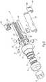
figure 1 is a perspective exploded view of a device according to a first embodiment of the invention;figure 2 is a perspective view of the device offigure 1 at a smaller scale ;figure 3 is a cut view along plane III onfigure 2 at a larger scale ;figure 4 is a schematic representation of the use of a system including the device offigures 1 to 3 ;figure 5 is a perspective exploded view, similar tofigure 1 , for a device according to a second embodiment of the invention;figure 6 is a perspective view of the device offigure 1 at a smaller scale ;figure 7 is a cut view along plane VII onfigure 6 at a larger scale;figure 8 is a bloc diagram of a method for using the device offigures 1 to 3 or the device offigures 5 to 7 .- The
device 2 represented onfigures 1 to 3 constitutes a probe which belongs to a system schematically represented onfigure 4 . Figures 1 to 3 show the structure ofdevice 2, whereasfigure 4 includes a functional representation of this device.Device 2 includes arigid body 20 made of a synthetic material such as plastic ABS or Nylon (registered trademark). Thisbody 20 is centered on a longitudinal axis X2 and extends between afront end 22 and arear end 24.- Next to
front end 22,body 20 defines an openedcavity 26 which is obturated by aflexible membrane 28 made of an elastomer material, such as silicon, polyester, poly(methyl) methacrylate or PMMA.Membrane 28 is optically transparent in the visible range. Membrane 28 is held in position onfront end 22 ofbody 20 by a retainingring 30 which is mounted around afront portion 20A ofbody 20 and pinchesmembrane 28 around an outer radial surface S20 of this front portion.- Three piezoelectric
ceramic transducers 32 are mounted withinfront portion 20A ofbody 20 with theiractive faces 322 oriented towardsmembrane 28 and towards axis X2.Transducers 32 are regularly distributed around axis X2. These threetransducers 32 are designed and mounted ontobody 20 in such a way that the ultrasonic waves respectively originating from these three ultrasound sources are focused and converge to a common focal point P which is located on axis X2, beyondmembrane 28 with respect totransducers 32. Ultrasound sources formed bytransducers 32 can also be said to be confocal at point P. Transducers 32 work at a frequency between 0,1 and 10 MHz, preferably between 500 kHz and 3 MHZ and more preferably equal to about 1,6 MHz. Each time, atransducer 32 is actuated for a duration between 5 and 20 seconds.Membrane 28 is also acoustically transparent in the frequency working range oftransducers 32.- When it is mounted on
body 20,ring 30 has anend face 302 which is flush with aterminal edge 202 offront portion 20A. Thus,edge 202 and end face 302 together define an end surface S2 ofdevice 2 which is perpendicular to axis X2. Focal point P is beyond surface S2 with respect to the three ultrasound sources formed bytransducers 32. - The
active surface 322 of eachtransducer 32 is in the form of a portion of the sphere centered on this focal point. Actually, the wall ofbody 20 which definescavity 26 may also be in the form of a portion of a sphere centered on this focal point P, which makes the assembly ofdevice 2 easier. However, another shape is also possible for this cavity. Eachtransducer 32 is mounted within a housing formed by ahole 206 which extends throughfront portion 20A. Whentransducers 32 are mounted within theirrespective housings 206, theiractive surfaces 322 define, together with an inner surface offront portion 20A andmembrane 28,cavity 26. - As visible on
figure 3 ,ring 30 is provided, next to endface 302, with a reduced diameter inner radial surface S30 whose diameter is adjusted to the diameter of outer radial surface S20, so thatmembrane 28 is efficiently pinched between surfaces S30 and S20.Ring 30 also includes askirt 306 which has an axial length, measured along axis X2, selected so thatring 30 bears against an annular outer collar 20D ofbody 20 whenring 30 is mounted aroundbody 20. In this configuration,surface 302 is flush withedge 202, as mentioned here-above. - Actually, collar 20D separates
front portion 20A andrear portion 20B ofbody 20. Skirt 306 extends at a slight radial distance of surface S20, which avoids a risk of wedgingring 30 when it is mounted ontobody 20.- On
figure 1 ,membrane 28 is represented on the left ofring 30, that is in front of it. Actually, when it is mounted onbody 20,membrane 28 is located at the level ofsurface 302 along axis X2 and radially between surfaces S20 and S30, where it is pinched. Thus, when it is mounted onbody 20,membrane 28 belongs to end surface S2. Cavity 26 is filled with a coupling medium, more particularly a coupling fluid, which allows ultrasonic waves originating fromtransducers 32 to propagate withincavity 26. The coupling fluid is selected in order not to attenuate, or to attenuate as little as possible, ultrasound waves coming fromtransducers 32. For instance, it can be made of water cleared of gases. Alternatively, the coupling medium can be made of a gel.- This coupling medium is selected in order to minimize reflection and refraction of ultrasounds on
membrane 28 and in order to maximize ultrasound transmission through this membrane. This coupling medium is identified withreference 34 onfigures 3 and4 . It is optically transparent, at least in the visible range. Here-after, Z1 denotes the acoustic impedance of a tissue to be treated withsystem 4 and c1 denotes the ultrasound waves velocity within this tissue. Similarly, Z34 and c34 denote the acoustic impedance and ultrasound wave's velocity ofmedium 34. Considering the case wheredevice 2 is used to treat varicose veins in a human body, and considering that transmission is optimal when Z34 equals Z1 and c34 equals c1, one chooses a coupling medium with an acoustic impedance between 1,35 and 1,65 106.kg·s-1·m-2, more preferably equal to about 1.54 106.kg·s-1·m-2 . Thus,coupling medium 34 is acoustically transparent for the ultrasonic waves emitted bytransducers 32, i.e. in the frequency working range oftransducers 32. - Moreover, in order not to alter the acoustic waves coming out of
transducers 32,membrane 28 is chosen with parallel main surfaces, at least in its portion perpendicular to axis X2. In other words, its main surfaces perpendicular to axis X2 are parallel to each other. Its thickness is below 100 micrometers (µm), preferably below 50 µm, more preferably equal to about 35 µm. The material ofmembrane 28 is preferably transparent to ultrasound waves. - A series of light sources formed by some
LEDs 40 is mounted withinring 30. Actually,ring 30 is provided with twenty through-holes 304 and oneLED 40 is installed within each through-hole. Through-holes 304 are regularly distributed around axis X2 whenring 30 is mounted onbody 20. Through-holes are each aligned on an axis A304 and all axes A 304 converge on a point Q which belongs to axis X2. As visible onfigure 3 , point Q is further away frommembrane 28 and surface S2 than focal point P. - A target zone Z1 is defined, which includes points P and Q and is centered on axis X2.
Transducers 32 andLEDs 40 are oriented towards target zone Z1. Target zone Z1 is identified with hatches onfigures 3 and4 . Its actual shape depends on the structure and control oftransducers 32 andLEDs 40. LEDs 40 are oriented towards axis X2 and their respective light beams B40 converge to the front, towards this axis, with an angle of convergence α between 45 and 60°. In other words, these light beams B40 make an angle between 30 and 45° with the skin of a patient whendevice 2 is in use. This angle with the skin of a patient is also the angle between beams B40 and endface 302.LEDs 40 are mounted onbody 20 viaring 30.LEDs 40 are used to enlighten or illuminate the skin of a subject or patient whendevice 2 is in use. Actually,LEDs 40 enlighten or illuminate not only the outer surface of the skin of the subject but also a portion of the tissue located below the skin, via sub surface scattering.Device 2 also includes avideo camera 50 which is mounted withinbody 20. In other words,video camera 50 is embedded inbody 20. More precisely,body 20 has an innercylindrical wall 20C which defines a recess, centered on axis X2 for accommodatingvideo camera 50. Anelastomeric gasket 52 is mounted withinwall 20C and holdsvideo camera 50 within the recess. Video camera works in the visible range. In practice,video camera 50 is a micro video camera, that is a camera with a length smaller than or equal to 20 mm, preferably 15 mm, and a diameter smaller than or equal to 25 mm, preferably 15 mm.Video camera 50 is arranged withinbody 20 in such a way that its boresight is aligned with axis X2. The boresight ofcamera 50 is oriented towardsmembrane 28, in the direction of arrow A50 onfigure 3 . Thus,camera 50 is also oriented towards target zone Z1.Camera 50 is separated fromcavity 26 by atransparent part 54, more precisely a cylindrical part centered on axis X2 and made of poly(methyl) methacrylate or PMMA, also known as Plexiglas (registered trademark). Thispart 54 allowscamera 50 capturing pictures throughcavity 26 andmembrane 28.- The low thickness of
membrane 28 avoids perturbating waves going through this membrane, including ultrasonic waves coming fromtransducers 32 and images captured byvideo camera 50. In other words, no significant visual interference or sound attenuation is generated bymembrane 28. Device 2 also includes a printed circuit board orPCB 60 which is received within itsrear portion 20B and which is used to controltransducer 32 andcamera 50 and to connect them to other parts ofsystem 4.Body 20 also includes acover 20E which is adapted to be mounted onrear portion 20B onceitems body 20. Acontrol switch 70 is mounted oncover 20E and is used by a practitioner in order to activatetransducers 32 viaPCB 60, when appropriate.- A
rear cap 80 is mounted onrear end 24 and a rear portion ofcover 20E.Rear cap 80 holdscover 20E in position with respect to the remaining portions ofbody 20. Apart fromcover 20E,body 20 is integral.Rear cap 80 is provided with holes or connectors to allow electrical connection ofdevice 2 to other parts ofsystem 4 via electric lines which are not represented onfigures 1 to 3 . One such hole is visible onfigure 3 . Actually, onfigures 1 to 3 , no electric cable is represented, for the sake of clarity. - As shown on
figures 1 to 3 , the general cylindrical shape ofdevice 2 allows it to be held in one hand, with one finger pressing onswitch 70 when necessary. Body 20 is provided, in itssurface defining cavity 26, with non represented recesses to accommodate bubbles potentially formed withinmedium 34 during use ofdevice 2. Moreover, a channel is formed throughbody 20 in order to fillcavity 26 withcoupling medium 34, the outlet of this channel is visible onfigure 3 , withreference 38.- In the use configuration shown on
figure 4 ,PCB 60 is used to match the impedance in order to drivetransducers 32 which generate acoustic waves focused on point P. Onfigure 4 , arrows S60 represent the control oftransducers 32 byPCB 60. - In the example of
figure 4 , a varicose vein V of a subject's tissue T is to be treated for destruction of its endothelium. Camera 50 is used to efficiently locate or "place"device 2 with respect to tissue T, more particularly to its skin S, in order for this point P to coincide with varicose vein V or similar irregularities. When usingsystem 4, the practitioner starts, in a first step a) represented onfigure 8 , by placingdevice 2 in contact with a primary zone of the patient's skin S where veins V to be treated are likely to be located. Identification of this primary zone can be performed with unaided eye.- The method also includes a step b) where
transducers 32 are actuated, in order to generate cavitation bubbles within the patient's body, as mentioned here-above. - A step c) is also implemented, where an image feedback of the tissue is obtained via
camera 50. - In order for steps b) and c) to be realized efficiently, a step d) is implemented where
LEDs 40 are actuated. During step b), the light beams B40 coming out ofdiodes 40 enlighten the portion of tissue T immediately adjacent tomembrane 28 and to front end surface S2 ofdevice 2, which allowscamera 50 to capture images within a cone C50 which represents its visibility zone. In other words, a zone Z2 of tissue T, which is identified in grey onfigure 4 , is targeted or enlightened via diffusion of light by beams B40. This zone Z2 includes a disc of skin S and a layer of tissue T below this disc. This allowsvideo camera 50, which is a relatively simple and inexpensive device, to efficiently capture images allowing visualizing vein V. - Illumination of zone Z2 by
LEDs 40 occurs as long ascamera 50 captures images. In other words, step c) occurs only when step d) is implemented. - Advantageously, step b) also occurs only when step d) is implemented.
System 4 also includes a screen 6 which is connected tovideo camera 50 via a connecting line L6 and where an image V' of vein V, captured byvideo camera 50, can be shown in a further step e) of the method. A user ofsystem 4 who hasdevice 2 in hand and watches screen 6 can thus adapt the position ofdevice 2 with respect to tissue T, in a further step f), in order to efficiently treat vein V by focusing beams B40 on this part of tissue T. In other words, step f) is implemented by thepractitioner using device 2 to adapt the placement ofdevice 2 with respect to the patient's skin S and tissue T. During steps e) and f), steps b), c) and d) are still implemented. In particular, the user can movedevice 2 along vein V in order to make point P coincident with vein V on several locations, for treating this vein along its path within tissue T.- In order to take into account possible variations of the ambient lighting and possible variations of the response of the tissue T to the light emitted by
LEDs 40,video camera 50 preferably has automatic gain control. This allows optimizing the contrast of the images to display the veins or irregularities on screen 6. System 4 also includes asignal coupler 8, anelectronic control unit 10 for acquiring and treating a signal S8 coming out ofsignal coupler 8, asignal generator 12 controlled byunit 10 via a control signal S10 and anamplifier 14 which delivers tocoupler 8 an amplified signal S14.- According to an advantageous aspect of the invention,
transducers 32 can also be used in order to control cavitation by monitoring ultrasonic waves within tissue T. In such a case, an output signal S32 of eachtransducer 32, which corresponds to the level of scattered ultrasonic waves, is delivered toPCB 60 which provides it to signalcoupler 8 andelectronic control unit 10. An output device, such as aloudspeaker 16, is used to inform the practitioner or user ofsystem 4 of the efficiency of the cavitation level within tissue T. For instance, the level and/or frequency of the sound emitted byloudspeaker 16 can be based on the output signal S32 oftransducers 32, thus be representative of the level of scattered ultrasonic waves. - Alternatively, instead of
loudspeaker 16, other means can be used to inform the practitioner about the detected ultrasonic waves, such as a dedicated screen, a subscreen of screen 6 or a LED or lamp visible by the practitioner which blinks when cavitation takes place, etc... - According to an alternative embodiment of the invention, sensors different from
transducers 32 can be used in order to provide information toelectronic control unit 10 with respect to the cavitation level within tissue T. - From a practical point of view, it appears that the wavelength of the light emitted by
LEDs 40, which is in the visible range, can be selected between 586 and 605 nanometers (nm), in particular in the yellow and/orange spectrum, which allows an efficient illumination of zone Z2, including by sub surface scattering or SSS. - As shown on
figure 3 , rearportion 20BA body 20 is provided withslides 20F for holdingPCB 60 in position. These slides can also be used to house one or several tubes for feedingcavity 26 withcoupling medium 34. In such a case, these tubes are connected to the channel whose outlet is visible withreference 38 onfigure 3 . Ring 30 has abeveled surface 303 which converges towardsend face 302. This allowssurface 302, which defines the interface betweendevice 2 and skin S during use ofdevice 2, having a diameter D302 substantially smaller than the outer diameter D30 ofring 30 which cannot be reduced sinceLEDs 40 are accommodated within this ring. This enables reducing the friction surface on the skin S of the subject or patient to a disc of diameter D302. In practice, beveledsurface 303 is dimensioned and oriented so that an angle β betweensurfaces Device 2 is easy to manipulate, with one hand, by a practitioner who can watch screen 6 as explained here-above.Device 2 is used as a big pen or probe, which is consistent with its ergonomics. Actually, depending on the habits of a practitioner, he/she might gripbody 20 with different fingers so that the placement and displacement ofdevice 2 with respect to tissue T might be different from one user to the other. In order to take this into account, and according to a non-represented aspect of the invention, the position and/or orientation ofvideo camera 50 withinbody 20 is adjustable.- Since
LEDs 40 are mounted withinring 30 which comes into contact with the skin S of a patient when the practitioner starts usingdevice 2 and bears against skin S when lighting means are activated, the quantity of light transferred fromLEDs 40 to enlightened zone Z2 is maximal. This improves the quality of the images captured byvideo camera 50. - In the second embodiment of the invention represented on
figures 5 to 7 , the portions ofdevice 2 of the second embodiment which are similar to the ones of the first embodiment have the same references. This second device orprobe 2 can also be used as a part of the system offigure 4 and works substantially asdevice 2 of the first embodiment. Here-after, only the differences with the first embodiment are explained. - The
rear cap 80 is formed of twohalves elastic tongues 80C andcorresponding recesses 80D. In this embodiment, theLEDs 40 are received within throughholes 204 evenly distributed around axis X2 and provided within collar 20D. Figure 7 shows oneslide 20F ofbody 20 aligned with a channel 20G which has anoutlet 38 connected tocavity 26. A non represented tube can be installed withinslide 20F in order to feed channel 20G andcavity 26. This cavity is made within afront portion 20A ofbody 20 surrounded by three rings, namely aninner ring 31, anintermediate ring 33 and anouter ring 35. A holdingmember 53 is provided at the interface betweenrings Ring 35 is aligned, along a direction parallel to axis X2, with light sources constituted byLEDs 40 and forms a wave guide for the light emitted by these LEDs, towards an end surface S2 ofdevice 2.- This second embodiment has been designed to be compatible with an adjustment of the axial distance defined between focal point P and
membrane 28, allowing the practitioner to adjust depth of penetration of the cavitation into tissue T. This is to treat more or less deep veins. For thatpurpose ring 31 is designed with an external thread which fits with an internal thread provided onring 33. Thisring 33 is also equipped with acircumferential groove 51 in which a non-represented O-ring is inserted.Ring 31 is hermetically bonded onfront portion 20A ofbody 20.Ring 33 is screwed onring 31 andmembrane 28 is pinched by holdingmember 53 onring 33 or bonded directly on the holdingmember 53. This assembly can be filled with coupling liquid and remains hermetic whatever the position of thering 33 along axis X2 is, thanks to O-ring located ingroove 51.Ring 35 is made of a transparent material, like PMMA or another transparent plastics. It is inserted onring 33 and insures conduction of the light emitted by theLEDs 40. - The
front edge 352 ofouter ring 35 is beveled rearwardly towards axis X2 andmembrane 28 is pinched betweenrings - A
ring 37 is mounted aroundrear portion 20B and collar 20D ofbody 20 and protectsLEDs 40 and their wiring against contact with the user. As in the first embodiment,transducers 32 which form ultrasound wave sources,LEDs 40 andvideo camera 50 are mounted onbody 20. In this case,LEDs 40 are directly mounted withinholes 204 formed inbody 20, whereas in the first embodiment,LEDs 40 are mounted onbody 20 viaring 30 which is immobilized onto this body. - In this second embodiment,
transducers 32,LEDs 40 andcamera 50 are also oriented towards a target zone Z1 visible onfigure 6 , which includes focal point P oftransducers 32 and convergence point Q ofLEDs 40. Device 2 of this second embodiment can be used to implement the method offigure 8 .- In both embodiments, the use of LEDs as lighting means is advantageous in terms of life time and because of the relatively low temperature of a diode, as compared to an incandescent bulb, which avoids burning the skin of a patient. Moreover, the lighting power of LEDs can be easily adjusted.
- In both embodiments, the fact that the boresight of
video camera 50 is aligned on central axis X2 induces that this boresight is globally perpendicular to the skin 5 of the patient whendevice 2 is in use. This makes it more intuitive to use. - In both embodiments, since
LEDs 40 are located aroundtransducers 32, light beams B40 do not have to crosscavity 26. This avoids reflection issues with respect to light beams B40crossing coupling medium 34, whereas such a reflection could alter the quality of the images captured byvideo camera 50. - The invention is explained here above in
case device 2 includes three ultrasound sources formed bytransducers 32. However, it can also work with a single ultrasound source, with two such sources or with four such sources or more. With a single transducer used as an ultrasound source, the bubbles can be pushed away by a radiation force. This is why, in such a case, one should prefer a highly focalized ultrasound source. The interest of using several ultrasound sources is to create a network of interferences in a focal zone, where the cavitation bubbles can be trapped. Another interest of this approach is to reduce the size of the focal volume for improving treatment spatial resolution. - The invention is explained here-above in case video camera works in the visible range. Alternatively, an infra-red (IR) video camera can be used. In such a case,
membrane 28 andcoupling medium 34 are optically transparent in the IR range and the light used to enlighten zone Z2 is adapted. - According to another approach, a lighting light with a different wavelength, e.g. ultraviolet, might be used to highlight a specific target. This could be coupled to the injection of a fluorescent agent.
- The invention is explained here above in case it is used for treating a varicose vein. It can also be used for the treatment of acne, wrinkles, cellulites, tattoos, melanoma and/or lentigines. It can also be used for generating ultrasonic waves in a human or animal body.
- According to a non represented alternative embodiment of the invention, the coupling medium which fills
cavity 26 can be solid. In such a case,membrane 28 can be omitted.
Claims (15)
- Device (2) for generating ultrasonic waves in a target region (V) of a soft solid (T), this device including at least one ultrasound source (32) for generating ultrasonic waves in the soft solid, lighting means, for enlightening a zone (Z2) of the soft solid (T), and a video camera (50), for capturing images (V') in the zone (Z2) enlightened by the lighting means, wherein:- the device includes at least two ultrasound sources (32), preferably three ultrasound sources, mounted on a body (20) of the device and focused at a common focal point (P) in a target zone (Z1), beyond an end surface (52) of the device with respect to the ultrasound sources,- the lighting means include several light sources (40) for enlightening the zone (Z2) of the soft solid (T) via subsurface scattering, the light sources being distributed around a central axis (X2) of the device that includes a focal point (P) of all the ultrasound sources (32),- the ultrasound sources (32), the lighting sources (40) and the video camera (50) are mounted on the body (20) of the device and oriented toward the common focal point (P) in the target zone (Z1),- a boresight (A50) of the video camera (50) is aligned on the central axis (X2) of the device (2).
- A device according to claim 1,characterized in that a cavity (26) located in front of all ultrasound source(s) (32) is filled with a coupling medium (34) and, in case this coupling medium is liquid, obturated by a membrane (28) which belongs to an end surface (32) of the device (2), is flexible, acoustically and optically transparent, has parallel main surfaces and a thickness below 100 µm, preferably below 50 µm, more preferably equal to about 35 µm.
- A device according to claim 2,characterized in that the coupling medium (34) has an acoustic impedance between 1,45 and 1,65 106.kg·s-1·m-2, more preferably equal to about 1.54 106.kg·s-1·m-2, and is optically transparent.
- A device according to one of claims 2 or 3,characterized in that the light sources (40) are distributed around the cavity (26).
- A device according to one of claims 2 to 4,characterized in that the light sources (40) are mounted within a series of holes (204; 304) provided on said body (20) or on a ring (30) mounted around said body, said holes being distributed around the central axis (X2) in such a way that light beams (B40) emitted by the light sources (40) do not cross the cavity (26).
- A device according to one of claims 2 to 5,characterized in that the boresight (A50) of the video camera (50) crosses a transparent part (54), also mounted on the body (20) and which separates the video camera from the cavity (26).
- A device according to any preceding claims,characterized in that the lighting means (40) are located around the ultrasound source (32).
- A device according to any preceding claim,characterized in that the light sources are made of LEDs (40).
- A device according to claim 8,characterized in that the wavelength of the light emitted by the LEDs (40) is selected between 586 and 605 nm, in particular in the yellow and/or orange spectrum.
- A device according to any preceding claim,characterized in that the video camera (50) has automatic gain control.
- A device according to any preceding claim,characterized in that it includes detection means (32), in particular some ultrasonic transducers (32) which also constitute the ultrasound sources, for detecting ultrasonic waves in the target region (V) and means (16) for providing a user with a signal representative of the level of scattered ultrasonic waves.
- A device according to any preceding claim,characterized in that the lighting means (40) are mounted on a support member (30) adapted to come into contact with and to bear against a surface (S) of the soft solid (T).
- A device according to any preceding claim,characterized in that the body (20) is designed and configured to be held in one hand.
- A device according to any preceding claim,characterized in that the position and/or orientation of the video camera (50) within the body of the device is adjustable.
- A system (4) for generating ultrasonic waves in a target region (V) of a soft solid (T), this system including:- a device (2) according to any preceding claim,- a screen (6) for displaying images captured by the video camera (50) of the device.
Priority Applications (3)
| Application Number | Priority Date | Filing Date | Title |
|---|---|---|---|
| RS20191359ARS59504B1 (en) | 2015-09-29 | 2016-09-29 | Device and system for generating ultrasonic waves in a target region of a soft solid and method for locally treating a tissue |
| SI201630476TSI3355795T1 (en) | 2015-09-29 | 2016-09-29 | Device and system for generating ultrasonic waves in a target region of a soft solid and method for locally treating a tissue |
| PL16774659TPL3355795T3 (en) | 2015-09-29 | 2016-09-29 | Device and system for generating ultrasonic waves in a target region of a soft solid and method for locally treating a tissue |
Applications Claiming Priority (2)
| Application Number | Priority Date | Filing Date | Title |
|---|---|---|---|
| EP15306525 | 2015-09-29 | ||
| PCT/EP2016/073191WO2017055403A1 (en) | 2015-09-29 | 2016-09-29 | Device and system for generating ultrasonic waves in a target region of a soft solid and method for locally treating a tissue |
Publications (2)
| Publication Number | Publication Date |
|---|---|
| EP3355795A1 EP3355795A1 (en) | 2018-08-08 |
| EP3355795B1true EP3355795B1 (en) | 2019-07-31 |
Family
ID=54251464
Family Applications (1)
| Application Number | Title | Priority Date | Filing Date |
|---|---|---|---|
| EP16774659.3AActiveEP3355795B1 (en) | 2015-09-29 | 2016-09-29 | Device and system for generating ultrasonic waves in a target region of a soft solid and method for locally treating a tissue |
Country Status (13)
| Country | Link |
|---|---|
| US (1) | US11540806B2 (en) |
| EP (1) | EP3355795B1 (en) |
| JP (1) | JP7099953B2 (en) |
| BR (1) | BR112018006290A2 (en) |
| CA (1) | CA3000058A1 (en) |
| DK (1) | DK3355795T3 (en) |
| ES (1) | ES2753608T3 (en) |
| HU (1) | HUE045886T2 (en) |
| PL (1) | PL3355795T3 (en) |
| PT (1) | PT3355795T (en) |
| RS (1) | RS59504B1 (en) |
| SI (1) | SI3355795T1 (en) |
| WO (1) | WO2017055403A1 (en) |
Families Citing this family (27)
| Publication number | Priority date | Publication date | Assignee | Title |
|---|---|---|---|---|
| US8444562B2 (en) | 2004-10-06 | 2013-05-21 | Guided Therapy Systems, Llc | System and method for treating muscle, tendon, ligament and cartilage tissue |
| US10864385B2 (en) | 2004-09-24 | 2020-12-15 | Guided Therapy Systems, Llc | Rejuvenating skin by heating tissue for cosmetic treatment of the face and body |
| US8535228B2 (en) | 2004-10-06 | 2013-09-17 | Guided Therapy Systems, Llc | Method and system for noninvasive face lifts and deep tissue tightening |
| US11883688B2 (en) | 2004-10-06 | 2024-01-30 | Guided Therapy Systems, Llc | Energy based fat reduction |
| US9694212B2 (en) | 2004-10-06 | 2017-07-04 | Guided Therapy Systems, Llc | Method and system for ultrasound treatment of skin |
| US8690779B2 (en) | 2004-10-06 | 2014-04-08 | Guided Therapy Systems, Llc | Noninvasive aesthetic treatment for tightening tissue |
| US8133180B2 (en) | 2004-10-06 | 2012-03-13 | Guided Therapy Systems, L.L.C. | Method and system for treating cellulite |
| US11235179B2 (en) | 2004-10-06 | 2022-02-01 | Guided Therapy Systems, Llc | Energy based skin gland treatment |
| US11724133B2 (en) | 2004-10-07 | 2023-08-15 | Guided Therapy Systems, Llc | Ultrasound probe for treatment of skin |
| US11207548B2 (en) | 2004-10-07 | 2021-12-28 | Guided Therapy Systems, L.L.C. | Ultrasound probe for treating skin laxity |
| US12102473B2 (en) | 2008-06-06 | 2024-10-01 | Ulthera, Inc. | Systems for ultrasound treatment |
| KR20110091832A (en) | 2008-06-06 | 2011-08-12 | 얼테라, 인크 | Tissue Imaging and Treatment Systems |
| CA2748362A1 (en) | 2008-12-24 | 2010-07-01 | Michael H. Slayton | Methods and systems for fat reduction and/or cellulite treatment |
| CN104027893B (en) | 2013-03-08 | 2021-08-31 | 奥赛拉公司 | Apparatus and method for multifocal ultrasound therapy |
| WO2015160708A1 (en) | 2014-04-18 | 2015-10-22 | Ulthera, Inc. | Band transducer ultrasound therapy |
| JP6979882B2 (en) | 2015-06-24 | 2021-12-15 | ザ リージェンツ オブ ザ ユニヴァシティ オブ ミシガン | Tissue disruption therapy systems and methods for the treatment of brain tissue |
| ES2939604T3 (en) | 2016-01-18 | 2023-04-25 | Ulthera Inc | Compact ultrasonic device having an annular ultrasonic array peripherally electrically connected to a flexible printed circuit board |
| PL3981466T3 (en) | 2016-08-16 | 2023-11-20 | Ulthera, Inc. | Systems and methods for cosmetic ultrasound treatment of skin |
| TWI797235B (en) | 2018-01-26 | 2023-04-01 | 美商奧賽拉公司 | Systems and methods for simultaneous multi-focus ultrasound therapy in multiple dimensions |
| US11944849B2 (en) | 2018-02-20 | 2024-04-02 | Ulthera, Inc. | Systems and methods for combined cosmetic treatment of cellulite with ultrasound |
| EP3530179A1 (en)* | 2018-02-27 | 2019-08-28 | Koninklijke Philips N.V. | Obtaining images for use in determining one or more properties of skin of a subject |
| AU2019389001B2 (en) | 2018-11-28 | 2025-08-14 | Histosonics, Inc. | Histotripsy systems and methods |
| US12377293B2 (en) | 2019-07-15 | 2025-08-05 | Ulthera, Inc. | Systems and methods for measuring elasticity with imaging of ultrasound multi-focus shearwaves in multiple dimensions |
| US11813485B2 (en) | 2020-01-28 | 2023-11-14 | The Regents Of The University Of Michigan | Systems and methods for histotripsy immunosensitization |
| JP2023540482A (en) | 2020-08-27 | 2023-09-25 | ザ リージェンツ オブ ザ ユニバーシティー オブ ミシガン | Ultrasonic transducer with transmitting and receiving functions for histotripsy |
| EP4608504A1 (en) | 2022-10-28 | 2025-09-03 | Histosonics, Inc. | Histotripsy systems and methods |
| KR102561454B1 (en)* | 2023-05-15 | 2023-07-31 | (주)울파인 | Ultrasonic skin beauty device capable of adjusting penetration depth and preventing skin tissue damage |
Family Cites Families (18)
| Publication number | Priority date | Publication date | Assignee | Title |
|---|---|---|---|---|
| US5146923A (en)* | 1986-12-18 | 1992-09-15 | Dhawan Atam P | Apparatus and method for skin lesion examination |
| DE19615342C1 (en)* | 1996-04-18 | 1997-10-09 | Siemens Ag | Therapy appts. with optical positioning device |
| US7194117B2 (en)* | 1999-06-29 | 2007-03-20 | The Research Foundation Of State University Of New York | System and method for performing a three-dimensional virtual examination of objects, such as internal organs |
| US5879314A (en)* | 1997-06-30 | 1999-03-09 | Cybersonics, Inc. | Transducer assembly and method for coupling ultrasonic energy to a body for thrombolysis of vascular thrombi |
| WO2002009813A1 (en)* | 2000-07-31 | 2002-02-07 | El. En. S.P.A. | Method and device for epilation by ultrasound |
| US7309335B2 (en)* | 2003-12-31 | 2007-12-18 | Palomar Medical Technologies, Inc. | Dermatological treatment with visualization |
| US20120165848A1 (en)* | 2010-08-02 | 2012-06-28 | Guided Therapy Systems, Llc | System and method for treating cartilage |
| FR2886533B1 (en)* | 2005-06-03 | 2007-09-14 | Theraclion Soc Par Actions Sim | IMAGING AND PROCESSING HEAD OF LIVING ORGANS AND METHOD OF MANUFACTURING |
| KR100875208B1 (en) | 2005-12-09 | 2008-12-19 | 주식회사 메디슨 | High intensity focus ultrasound system |
| US9248318B2 (en)* | 2008-08-06 | 2016-02-02 | Mirabilis Medica Inc. | Optimization and feedback control of HIFU power deposition through the analysis of detected signal characteristics |
| US8353832B2 (en)* | 2008-10-14 | 2013-01-15 | Theraclion | Systems and methods for ultrasound treatment of thyroid and parathyroid |
| US20100217161A1 (en)* | 2009-02-25 | 2010-08-26 | Avi Shalgi | Delivery of therapeutic focused energy |
| EP2327450A1 (en)* | 2009-11-27 | 2011-06-01 | Theraclion SAS | A cover, a treatment device and a method of use of such a device |
| IL221863A (en)* | 2012-09-10 | 2014-01-30 | Elbit Systems Ltd | Digital system for surgical video capturing and display |
| KR20140095848A (en)* | 2013-01-25 | 2014-08-04 | 삼성전자주식회사 | Method and system for ultrasound treatment |
| US10350439B2 (en)* | 2013-03-28 | 2019-07-16 | University Of Washington Through Its Center For Commercialization | Focused ultrasound apparatus and methods of use |
| US20150065916A1 (en) | 2013-08-29 | 2015-03-05 | Vasculogic, Llc | Fully automated vascular imaging and access system |
| US9436993B1 (en)* | 2015-04-17 | 2016-09-06 | Clear Guide Medical, Inc | System and method for fused image based navigation with late marker placement |
- 2016
- 2016-09-29RSRS20191359Apatent/RS59504B1/enunknown
- 2016-09-29ESES16774659Tpatent/ES2753608T3/enactiveActive
- 2016-09-29DKDK16774659Tpatent/DK3355795T3/enactive
- 2016-09-29SISI201630476Tpatent/SI3355795T1/enunknown
- 2016-09-29JPJP2018516072Apatent/JP7099953B2/enactiveActive
- 2016-09-29PTPT167746593Tpatent/PT3355795T/enunknown
- 2016-09-29EPEP16774659.3Apatent/EP3355795B1/enactiveActive
- 2016-09-29USUS15/763,717patent/US11540806B2/enactiveActive
- 2016-09-29BRBR112018006290-1Apatent/BR112018006290A2/ennot_activeApplication Discontinuation
- 2016-09-29CACA3000058Apatent/CA3000058A1/ennot_activeAbandoned
- 2016-09-29HUHUE16774659Apatent/HUE045886T2/enunknown
- 2016-09-29PLPL16774659Tpatent/PL3355795T3/enunknown
- 2016-09-29WOPCT/EP2016/073191patent/WO2017055403A1/ennot_activeCeased
Non-Patent Citations (1)
| Title |
|---|
| None* |
Also Published As
| Publication number | Publication date |
|---|---|
| BR112018006290A2 (en) | 2018-10-16 |
| CA3000058A1 (en) | 2017-04-06 |
| EP3355795A1 (en) | 2018-08-08 |
| US11540806B2 (en) | 2023-01-03 |
| ES2753608T3 (en) | 2020-04-13 |
| WO2017055403A1 (en) | 2017-04-06 |
| US20180317884A1 (en) | 2018-11-08 |
| PL3355795T3 (en) | 2020-05-18 |
| DK3355795T3 (en) | 2019-10-28 |
| RS59504B1 (en) | 2019-12-31 |
| SI3355795T1 (en) | 2019-12-31 |
| PT3355795T (en) | 2019-11-04 |
| HUE045886T2 (en) | 2020-01-28 |
| JP7099953B2 (en) | 2022-07-12 |
| JP2018534966A (en) | 2018-11-29 |
Similar Documents
| Publication | Publication Date | Title |
|---|---|---|
| EP3355795B1 (en) | Device and system for generating ultrasonic waves in a target region of a soft solid and method for locally treating a tissue | |
| JP2018534966A5 (en) | ||
| CA2518315C (en) | Imaging system using diffuse infrared light | |
| EP4278979A3 (en) | Devices and methods for fractionated photoacoustic flow cytometry | |
| EP1685800A4 (en) | Thrombus detector, thrombus treating device, and methods therefor | |
| JP2013531999A (en) | System and method for identifying and locating an implanted device | |
| WO2008112723A1 (en) | Medical device including scanned beam unit for imaging and therapy | |
| WO2005052648A3 (en) | Endoscopic imaging and intervention system | |
| US11759167B2 (en) | Method and apparatus for visualizing a medical instrument under ultrasound guidance | |
| US20160235286A1 (en) | Medical Probe | |
| US20190247679A1 (en) | Ultrasound production source with an outside thread | |
| US5921930A (en) | Arrangement for locating concrements in a patient's body | |
| Xu et al. | Optical and acoustic monitoring of bubble cloud dynamics at a tissue-fluid interface in ultrasound tissue erosion | |
| US20150208924A1 (en) | Photoacoustic sensors with diffusing elements for patient monitoring | |
| CN116829230A (en) | Focusing ultrasonic equipment and image transducer protection method | |
| WO2016031700A1 (en) | Photoacoustic wave detector and photoacoustic imaging device | |
| KR101772480B1 (en) | Membrane for ultrasound apparatus, and ultrasound apparatus having same | |
| WO2018234282A1 (en) | CONTROL METHOD FOR TREATMENT OF BRAIN TISSUE | |
| KR20150051131A (en) | Method and apparatus for excitation pulse scanning in photoacoustic tomography | |
| JP6250510B2 (en) | Photoacoustic image generator | |
| JP2016064011A (en) | Photoacoustic image generation device | |
| JP6001230B2 (en) | Ultrasound endoscope, ultrasound observation apparatus, and ultrasound endoscope system | |
| KR101814995B1 (en) | Composite treatment cartridge and composite medical treatment apparatus having the same | |
| KR20160030649A (en) | Apparatus for ultrasound medical system | |
| KR20240123947A (en) | High intensity focused ultrasound device enabling to observe skin surface to be treated |
Legal Events
| Date | Code | Title | Description |
|---|---|---|---|
| STAA | Information on the status of an ep patent application or granted ep patent | Free format text:STATUS: UNKNOWN | |
| STAA | Information on the status of an ep patent application or granted ep patent | Free format text:STATUS: THE INTERNATIONAL PUBLICATION HAS BEEN MADE | |
| PUAI | Public reference made under article 153(3) epc to a published international application that has entered the european phase | Free format text:ORIGINAL CODE: 0009012 | |
| STAA | Information on the status of an ep patent application or granted ep patent | Free format text:STATUS: REQUEST FOR EXAMINATION WAS MADE | |
| 17P | Request for examination filed | Effective date:20180424 | |
| AK | Designated contracting states | Kind code of ref document:A1 Designated state(s):AL AT BE BG CH CY CZ DE DK EE ES FI FR GB GR HR HU IE IS IT LI LT LU LV MC MK MT NL NO PL PT RO RS SE SI SK SM TR | |
| AX | Request for extension of the european patent | Extension state:BA ME | |
| DAV | Request for validation of the european patent (deleted) | ||
| DAX | Request for extension of the european patent (deleted) | ||
| GRAP | Despatch of communication of intention to grant a patent | Free format text:ORIGINAL CODE: EPIDOSNIGR1 | |
| STAA | Information on the status of an ep patent application or granted ep patent | Free format text:STATUS: GRANT OF PATENT IS INTENDED | |
| INTG | Intention to grant announced | Effective date:20190130 | |
| GRAS | Grant fee paid | Free format text:ORIGINAL CODE: EPIDOSNIGR3 | |
| GRAJ | Information related to disapproval of communication of intention to grant by the applicant or resumption of examination proceedings by the epo deleted | Free format text:ORIGINAL CODE: EPIDOSDIGR1 | |
| GRAL | Information related to payment of fee for publishing/printing deleted | Free format text:ORIGINAL CODE: EPIDOSDIGR3 | |
| STAA | Information on the status of an ep patent application or granted ep patent | Free format text:STATUS: REQUEST FOR EXAMINATION WAS MADE | |
| GRAR | Information related to intention to grant a patent recorded | Free format text:ORIGINAL CODE: EPIDOSNIGR71 | |
| STAA | Information on the status of an ep patent application or granted ep patent | Free format text:STATUS: GRANT OF PATENT IS INTENDED | |
| GRAA | (expected) grant | Free format text:ORIGINAL CODE: 0009210 | |
| STAA | Information on the status of an ep patent application or granted ep patent | Free format text:STATUS: THE PATENT HAS BEEN GRANTED | |
| INTC | Intention to grant announced (deleted) | ||
| AK | Designated contracting states | Kind code of ref document:B1 Designated state(s):AL AT BE BG CH CY CZ DE DK EE ES FI FR GB GR HR HU IE IS IT LI LT LU LV MC MK MT NL NO PL PT RO RS SE SI SK SM TR | |
| INTG | Intention to grant announced | Effective date:20190625 | |
| REG | Reference to a national code | Ref country code:CH Ref legal event code:EP Ref country code:GB Ref legal event code:FG4D | |
| REG | Reference to a national code | Ref country code:AT Ref legal event code:REF Ref document number:1160080 Country of ref document:AT Kind code of ref document:T Effective date:20190815 | |
| REG | Reference to a national code | Ref country code:IE Ref legal event code:FG4D | |
| REG | Reference to a national code | Ref country code:DE Ref legal event code:R096 Ref document number:602016017818 Country of ref document:DE | |
| REG | Reference to a national code | Ref country code:CH Ref legal event code:NV Representative=s name:MICHELI AND CIE SA, CH | |
| REG | Reference to a national code | Ref country code:DK Ref legal event code:T3 Effective date:20191025 Ref country code:RO Ref legal event code:EPE | |
| REG | Reference to a national code | Ref country code:PT Ref legal event code:SC4A Ref document number:3355795 Country of ref document:PT Date of ref document:20191104 Kind code of ref document:T Free format text:AVAILABILITY OF NATIONAL TRANSLATION Effective date:20191025 | |
| REG | Reference to a national code | Ref country code:SE Ref legal event code:TRGR | |
| REG | Reference to a national code | Ref country code:NL Ref legal event code:FP | |
| REG | Reference to a national code | Ref country code:LT Ref legal event code:MG4D | |
| REG | Reference to a national code | Ref country code:NO Ref legal event code:T2 Effective date:20190731 | |
| REG | Reference to a national code | Ref country code:SK Ref legal event code:T3 Ref document number:E 32578 Country of ref document:SK | |
| REG | Reference to a national code | Ref country code:HU Ref legal event code:AG4A Ref document number:E045886 Country of ref document:HU | |
| PG25 | Lapsed in a contracting state [announced via postgrant information from national office to epo] | Ref country code:HR Free format text:LAPSE BECAUSE OF FAILURE TO SUBMIT A TRANSLATION OF THE DESCRIPTION OR TO PAY THE FEE WITHIN THE PRESCRIBED TIME-LIMIT Effective date:20190731 Ref country code:LT Free format text:LAPSE BECAUSE OF FAILURE TO SUBMIT A TRANSLATION OF THE DESCRIPTION OR TO PAY THE FEE WITHIN THE PRESCRIBED TIME-LIMIT Effective date:20190731 | |
| PGFP | Annual fee paid to national office [announced via postgrant information from national office to epo] | Ref country code:SK Payment date:20191029 Year of fee payment:4 Ref country code:MC Payment date:20191122 Year of fee payment:4 | |
| PG25 | Lapsed in a contracting state [announced via postgrant information from national office to epo] | Ref country code:IS Free format text:LAPSE BECAUSE OF FAILURE TO SUBMIT A TRANSLATION OF THE DESCRIPTION OR TO PAY THE FEE WITHIN THE PRESCRIBED TIME-LIMIT Effective date:20191130 Ref country code:AL Free format text:LAPSE BECAUSE OF FAILURE TO SUBMIT A TRANSLATION OF THE DESCRIPTION OR TO PAY THE FEE WITHIN THE PRESCRIBED TIME-LIMIT Effective date:20190731 Ref country code:LV Free format text:LAPSE BECAUSE OF FAILURE TO SUBMIT A TRANSLATION OF THE DESCRIPTION OR TO PAY THE FEE WITHIN THE PRESCRIBED TIME-LIMIT Effective date:20190731 | |
| PGFP | Annual fee paid to national office [announced via postgrant information from national office to epo] | Ref country code:SI Payment date:20191029 Year of fee payment:4 Ref country code:RS Payment date:20191029 Year of fee payment:4 | |
| REG | Reference to a national code | Ref country code:GR Ref legal event code:EP Ref document number:20190403284 Country of ref document:GR Effective date:20200213 | |
| REG | Reference to a national code | Ref country code:ES Ref legal event code:FG2A Ref document number:2753608 Country of ref document:ES Kind code of ref document:T3 Effective date:20200413 | |
| PG25 | Lapsed in a contracting state [announced via postgrant information from national office to epo] | Ref country code:EE Free format text:LAPSE BECAUSE OF FAILURE TO SUBMIT A TRANSLATION OF THE DESCRIPTION OR TO PAY THE FEE WITHIN THE PRESCRIBED TIME-LIMIT Effective date:20190731 | |
| PG25 | Lapsed in a contracting state [announced via postgrant information from national office to epo] | Ref country code:IS Free format text:LAPSE BECAUSE OF FAILURE TO SUBMIT A TRANSLATION OF THE DESCRIPTION OR TO PAY THE FEE WITHIN THE PRESCRIBED TIME-LIMIT Effective date:20200224 Ref country code:SM Free format text:LAPSE BECAUSE OF FAILURE TO SUBMIT A TRANSLATION OF THE DESCRIPTION OR TO PAY THE FEE WITHIN THE PRESCRIBED TIME-LIMIT Effective date:20190731 | |
| REG | Reference to a national code | Ref country code:DE Ref legal event code:R097 Ref document number:602016017818 Country of ref document:DE | |
| PLBE | No opposition filed within time limit | Free format text:ORIGINAL CODE: 0009261 | |
| STAA | Information on the status of an ep patent application or granted ep patent | Free format text:STATUS: NO OPPOSITION FILED WITHIN TIME LIMIT | |
| PG2D | Information on lapse in contracting state deleted | Ref country code:IS | |
| PG25 | Lapsed in a contracting state [announced via postgrant information from national office to epo] | Ref country code:IS Free format text:LAPSE BECAUSE OF FAILURE TO SUBMIT A TRANSLATION OF THE DESCRIPTION OR TO PAY THE FEE WITHIN THE PRESCRIBED TIME-LIMIT Effective date:20191030 | |
| 26N | No opposition filed | Effective date:20200603 | |
| REG | Reference to a national code | Ref country code:AT Ref legal event code:UEP Ref document number:1160080 Country of ref document:AT Kind code of ref document:T Effective date:20190731 | |
| REG | Reference to a national code | Ref country code:SK Ref legal event code:MM4A Ref document number:E 32578 Country of ref document:SK Effective date:20200929 | |
| PG25 | Lapsed in a contracting state [announced via postgrant information from national office to epo] | Ref country code:RS Free format text:LAPSE BECAUSE OF NON-PAYMENT OF DUE FEES Effective date:20200929 Ref country code:CY Free format text:LAPSE BECAUSE OF FAILURE TO SUBMIT A TRANSLATION OF THE DESCRIPTION OR TO PAY THE FEE WITHIN THE PRESCRIBED TIME-LIMIT Effective date:20190731 | |
| PG25 | Lapsed in a contracting state [announced via postgrant information from national office to epo] | Ref country code:SK Free format text:LAPSE BECAUSE OF NON-PAYMENT OF DUE FEES Effective date:20200929 Ref country code:MT Free format text:LAPSE BECAUSE OF FAILURE TO SUBMIT A TRANSLATION OF THE DESCRIPTION OR TO PAY THE FEE WITHIN THE PRESCRIBED TIME-LIMIT Effective date:20190731 | |
| PG25 | Lapsed in a contracting state [announced via postgrant information from national office to epo] | Ref country code:SI Free format text:LAPSE BECAUSE OF NON-PAYMENT OF DUE FEES Effective date:20200930 | |
| REG | Reference to a national code | Ref country code:SI Ref legal event code:KO00 Effective date:20210812 | |
| PGFP | Annual fee paid to national office [announced via postgrant information from national office to epo] | Ref country code:LU Payment date:20210920 Year of fee payment:6 Ref country code:FI Payment date:20210920 Year of fee payment:6 Ref country code:AT Payment date:20210920 Year of fee payment:6 Ref country code:CZ Payment date:20210819 Year of fee payment:6 Ref country code:IE Payment date:20210927 Year of fee payment:6 | |
| PGFP | Annual fee paid to national office [announced via postgrant information from national office to epo] | Ref country code:BE Payment date:20210927 Year of fee payment:6 Ref country code:HU Payment date:20210920 Year of fee payment:6 Ref country code:PL Payment date:20210819 Year of fee payment:6 Ref country code:GR Payment date:20210920 Year of fee payment:6 Ref country code:RO Payment date:20210827 Year of fee payment:6 Ref country code:SE Payment date:20210916 Year of fee payment:6 Ref country code:DK Payment date:20210927 Year of fee payment:6 | |
| PGFP | Annual fee paid to national office [announced via postgrant information from national office to epo] | Ref country code:NO Payment date:20211001 Year of fee payment:6 Ref country code:BG Payment date:20210930 Year of fee payment:6 | |
| PG25 | Lapsed in a contracting state [announced via postgrant information from national office to epo] | Ref country code:MK Free format text:LAPSE BECAUSE OF FAILURE TO SUBMIT A TRANSLATION OF THE DESCRIPTION OR TO PAY THE FEE WITHIN THE PRESCRIBED TIME-LIMIT Effective date:20190731 Ref country code:MC Free format text:LAPSE BECAUSE OF NON-PAYMENT OF DUE FEES Effective date:20200930 | |
| REG | Reference to a national code | Ref country code:NO Ref legal event code:MMEP | |
| PG25 | Lapsed in a contracting state [announced via postgrant information from national office to epo] | Ref country code:RO Free format text:LAPSE BECAUSE OF NON-PAYMENT OF DUE FEES Effective date:20220929 Ref country code:FI Free format text:LAPSE BECAUSE OF NON-PAYMENT OF DUE FEES Effective date:20220929 Ref country code:CZ Free format text:LAPSE BECAUSE OF NON-PAYMENT OF DUE FEES Effective date:20220929 | |
| PGFP | Annual fee paid to national office [announced via postgrant information from national office to epo] | Ref country code:CH Payment date:20230327 Year of fee payment:7 | |
| REG | Reference to a national code | Ref country code:DK Ref legal event code:EBP Effective date:20220930 | |
| REG | Reference to a national code | Ref country code:SE Ref legal event code:EUG | |
| REG | Reference to a national code | Ref country code:AT Ref legal event code:MM01 Ref document number:1160080 Country of ref document:AT Kind code of ref document:T Effective date:20220929 | |
| REG | Reference to a national code | Ref country code:BE Ref legal event code:MM Effective date:20220930 | |
| PGFP | Annual fee paid to national office [announced via postgrant information from national office to epo] | Ref country code:TR Payment date:20230327 Year of fee payment:7 Ref country code:PT Payment date:20230323 Year of fee payment:7 Ref country code:IT Payment date:20230323 Year of fee payment:7 | |
| PG25 | Lapsed in a contracting state [announced via postgrant information from national office to epo] | Ref country code:LU Free format text:LAPSE BECAUSE OF NON-PAYMENT OF DUE FEES Effective date:20220929 | |
| PGFP | Annual fee paid to national office [announced via postgrant information from national office to epo] | Ref country code:NL Payment date:20230331 Year of fee payment:7 | |
| PG25 | Lapsed in a contracting state [announced via postgrant information from national office to epo] | Ref country code:NO Free format text:LAPSE BECAUSE OF NON-PAYMENT OF DUE FEES Effective date:20220930 Ref country code:IE Free format text:LAPSE BECAUSE OF NON-PAYMENT OF DUE FEES Effective date:20220929 Ref country code:HU Free format text:LAPSE BECAUSE OF NON-PAYMENT OF DUE FEES Effective date:20220930 Ref country code:AT Free format text:LAPSE BECAUSE OF NON-PAYMENT OF DUE FEES Effective date:20220929 | |
| PG25 | Lapsed in a contracting state [announced via postgrant information from national office to epo] | Ref country code:SE Free format text:LAPSE BECAUSE OF NON-PAYMENT OF DUE FEES Effective date:20220930 Ref country code:GR Free format text:LAPSE BECAUSE OF NON-PAYMENT OF DUE FEES Effective date:20230406 | |
| PG25 | Lapsed in a contracting state [announced via postgrant information from national office to epo] | Ref country code:BE Free format text:LAPSE BECAUSE OF NON-PAYMENT OF DUE FEES Effective date:20220930 | |
| PG25 | Lapsed in a contracting state [announced via postgrant information from national office to epo] | Ref country code:DK Free format text:LAPSE BECAUSE OF NON-PAYMENT OF DUE FEES Effective date:20220930 | |
| REG | Reference to a national code | Ref country code:CH Ref legal event code:PL | |
| REG | Reference to a national code | Ref country code:NL Ref legal event code:MM Effective date:20231001 | |
| PG25 | Lapsed in a contracting state [announced via postgrant information from national office to epo] | Ref country code:PL Free format text:LAPSE BECAUSE OF NON-PAYMENT OF DUE FEES Effective date:20220929 | |
| PG25 | Lapsed in a contracting state [announced via postgrant information from national office to epo] | Ref country code:NL Free format text:LAPSE BECAUSE OF NON-PAYMENT OF DUE FEES Effective date:20231001 | |
| PG25 | Lapsed in a contracting state [announced via postgrant information from national office to epo] | Ref country code:NL Free format text:LAPSE BECAUSE OF NON-PAYMENT OF DUE FEES Effective date:20231001 | |
| PGFP | Annual fee paid to national office [announced via postgrant information from national office to epo] | Ref country code:DE Payment date:20240402 Year of fee payment:8 | |
| PG25 | Lapsed in a contracting state [announced via postgrant information from national office to epo] | Ref country code:CH Free format text:LAPSE BECAUSE OF NON-PAYMENT OF DUE FEES Effective date:20230930 | |
| PG25 | Lapsed in a contracting state [announced via postgrant information from national office to epo] | Ref country code:CH Free format text:LAPSE BECAUSE OF NON-PAYMENT OF DUE FEES Effective date:20230930 Ref country code:BG Free format text:LAPSE BECAUSE OF NON-PAYMENT OF DUE FEES Effective date:20220929 | |
| PG25 | Lapsed in a contracting state [announced via postgrant information from national office to epo] | Ref country code:PT Free format text:LAPSE BECAUSE OF NON-PAYMENT OF DUE FEES Effective date:20240401 | |
| PG25 | Lapsed in a contracting state [announced via postgrant information from national office to epo] | Ref country code:PT Free format text:LAPSE BECAUSE OF NON-PAYMENT OF DUE FEES Effective date:20240401 | |
| PGFP | Annual fee paid to national office [announced via postgrant information from national office to epo] | Ref country code:GB Payment date:20240923 Year of fee payment:9 | |
| PG25 | Lapsed in a contracting state [announced via postgrant information from national office to epo] | Ref country code:IT Free format text:LAPSE BECAUSE OF NON-PAYMENT OF DUE FEES Effective date:20230929 | |
| PG25 | Lapsed in a contracting state [announced via postgrant information from national office to epo] | Ref country code:IT Free format text:LAPSE BECAUSE OF NON-PAYMENT OF DUE FEES Effective date:20230929 | |
| PGFP | Annual fee paid to national office [announced via postgrant information from national office to epo] | Ref country code:ES Payment date:20241007 Year of fee payment:9 | |
| REG | Reference to a national code | Ref country code:DE Ref legal event code:R119 Ref document number:602016017818 Country of ref document:DE | |
| PG25 | Lapsed in a contracting state [announced via postgrant information from national office to epo] | Ref country code:DE Free format text:LAPSE BECAUSE OF NON-PAYMENT OF DUE FEES Effective date:20250401 | |
| PGFP | Annual fee paid to national office [announced via postgrant information from national office to epo] | Ref country code:FR Payment date:20250626 Year of fee payment:10 |