EP3354221A1 - Recanalizing occluded vessels using radiofrequency energy - Google Patents
Recanalizing occluded vessels using radiofrequency energyDownload PDFInfo
- Publication number
- EP3354221A1 EP3354221A1EP18156580.5AEP18156580AEP3354221A1EP 3354221 A1EP3354221 A1EP 3354221A1EP 18156580 AEP18156580 AEP 18156580AEP 3354221 A1EP3354221 A1EP 3354221A1
- Authority
- EP
- European Patent Office
- Prior art keywords
- longitudinal member
- occlusion
- distal end
- longitudinal
- energy
- Prior art date
- Legal status (The legal status is an assumption and is not a legal conclusion. Google has not performed a legal analysis and makes no representation as to the accuracy of the status listed.)
- Granted
Links
Images


Classifications
- A—HUMAN NECESSITIES
- A61—MEDICAL OR VETERINARY SCIENCE; HYGIENE
- A61B—DIAGNOSIS; SURGERY; IDENTIFICATION
- A61B18/00—Surgical instruments, devices or methods for transferring non-mechanical forms of energy to or from the body
- A61B18/04—Surgical instruments, devices or methods for transferring non-mechanical forms of energy to or from the body by heating
- A61B18/12—Surgical instruments, devices or methods for transferring non-mechanical forms of energy to or from the body by heating by passing a current through the tissue to be heated, e.g. high-frequency current
- A61B18/14—Probes or electrodes therefor
- A61B18/1492—Probes or electrodes therefor having a flexible, catheter-like structure, e.g. for heart ablation
- A—HUMAN NECESSITIES
- A61—MEDICAL OR VETERINARY SCIENCE; HYGIENE
- A61B—DIAGNOSIS; SURGERY; IDENTIFICATION
- A61B18/00—Surgical instruments, devices or methods for transferring non-mechanical forms of energy to or from the body
- A61B18/18—Surgical instruments, devices or methods for transferring non-mechanical forms of energy to or from the body by applying electromagnetic radiation, e.g. microwaves
- A61B18/1815—Surgical instruments, devices or methods for transferring non-mechanical forms of energy to or from the body by applying electromagnetic radiation, e.g. microwaves using microwaves
- A—HUMAN NECESSITIES
- A61—MEDICAL OR VETERINARY SCIENCE; HYGIENE
- A61B—DIAGNOSIS; SURGERY; IDENTIFICATION
- A61B18/00—Surgical instruments, devices or methods for transferring non-mechanical forms of energy to or from the body
- A61B18/18—Surgical instruments, devices or methods for transferring non-mechanical forms of energy to or from the body by applying electromagnetic radiation, e.g. microwaves
- A61B18/20—Surgical instruments, devices or methods for transferring non-mechanical forms of energy to or from the body by applying electromagnetic radiation, e.g. microwaves using laser
- A61B18/22—Surgical instruments, devices or methods for transferring non-mechanical forms of energy to or from the body by applying electromagnetic radiation, e.g. microwaves using laser the beam being directed along or through a flexible conduit, e.g. an optical fibre; Couplings or hand-pieces therefor
- A61B18/24—Surgical instruments, devices or methods for transferring non-mechanical forms of energy to or from the body by applying electromagnetic radiation, e.g. microwaves using laser the beam being directed along or through a flexible conduit, e.g. an optical fibre; Couplings or hand-pieces therefor with a catheter
- A61B18/245—Surgical instruments, devices or methods for transferring non-mechanical forms of energy to or from the body by applying electromagnetic radiation, e.g. microwaves using laser the beam being directed along or through a flexible conduit, e.g. an optical fibre; Couplings or hand-pieces therefor with a catheter for removing obstructions in blood vessels or calculi
- A—HUMAN NECESSITIES
- A61—MEDICAL OR VETERINARY SCIENCE; HYGIENE
- A61B—DIAGNOSIS; SURGERY; IDENTIFICATION
- A61B5/00—Measuring for diagnostic purposes; Identification of persons
- A61B5/0059—Measuring for diagnostic purposes; Identification of persons using light, e.g. diagnosis by transillumination, diascopy, fluorescence
- A—HUMAN NECESSITIES
- A61—MEDICAL OR VETERINARY SCIENCE; HYGIENE
- A61B—DIAGNOSIS; SURGERY; IDENTIFICATION
- A61B8/00—Diagnosis using ultrasonic, sonic or infrasonic waves
- A61B8/12—Diagnosis using ultrasonic, sonic or infrasonic waves in body cavities or body tracts, e.g. by using catheters
- A—HUMAN NECESSITIES
- A61—MEDICAL OR VETERINARY SCIENCE; HYGIENE
- A61B—DIAGNOSIS; SURGERY; IDENTIFICATION
- A61B90/00—Instruments, implements or accessories specially adapted for surgery or diagnosis and not covered by any of the groups A61B1/00 - A61B50/00, e.g. for luxation treatment or for protecting wound edges
- A61B90/36—Image-producing devices or illumination devices not otherwise provided for
- A61B90/37—Surgical systems with images on a monitor during operation
- A—HUMAN NECESSITIES
- A61—MEDICAL OR VETERINARY SCIENCE; HYGIENE
- A61M—DEVICES FOR INTRODUCING MEDIA INTO, OR ONTO, THE BODY; DEVICES FOR TRANSDUCING BODY MEDIA OR FOR TAKING MEDIA FROM THE BODY; DEVICES FOR PRODUCING OR ENDING SLEEP OR STUPOR
- A61M13/00—Insufflators for therapeutic or disinfectant purposes, i.e. devices for blowing a gas, powder or vapour into the body
- A61M13/003—Blowing gases other than for carrying powders, e.g. for inflating, dilating or rinsing
- A—HUMAN NECESSITIES
- A61—MEDICAL OR VETERINARY SCIENCE; HYGIENE
- A61M—DEVICES FOR INTRODUCING MEDIA INTO, OR ONTO, THE BODY; DEVICES FOR TRANSDUCING BODY MEDIA OR FOR TAKING MEDIA FROM THE BODY; DEVICES FOR PRODUCING OR ENDING SLEEP OR STUPOR
- A61M25/00—Catheters; Hollow probes
- A61M25/01—Introducing, guiding, advancing, emplacing or holding catheters
- A61M25/09—Guide wires
- A—HUMAN NECESSITIES
- A61—MEDICAL OR VETERINARY SCIENCE; HYGIENE
- A61M—DEVICES FOR INTRODUCING MEDIA INTO, OR ONTO, THE BODY; DEVICES FOR TRANSDUCING BODY MEDIA OR FOR TAKING MEDIA FROM THE BODY; DEVICES FOR PRODUCING OR ENDING SLEEP OR STUPOR
- A61M25/00—Catheters; Hollow probes
- A61M25/10—Balloon catheters
- A—HUMAN NECESSITIES
- A61—MEDICAL OR VETERINARY SCIENCE; HYGIENE
- A61M—DEVICES FOR INTRODUCING MEDIA INTO, OR ONTO, THE BODY; DEVICES FOR TRANSDUCING BODY MEDIA OR FOR TAKING MEDIA FROM THE BODY; DEVICES FOR PRODUCING OR ENDING SLEEP OR STUPOR
- A61M5/00—Devices for bringing media into the body in a subcutaneous, intra-vascular or intramuscular way; Accessories therefor, e.g. filling or cleaning devices, arm-rests
- A—HUMAN NECESSITIES
- A61—MEDICAL OR VETERINARY SCIENCE; HYGIENE
- A61N—ELECTROTHERAPY; MAGNETOTHERAPY; RADIATION THERAPY; ULTRASOUND THERAPY
- A61N7/00—Ultrasound therapy
- A61N7/02—Localised ultrasound hyperthermia
- A61N7/022—Localised ultrasound hyperthermia intracavitary
- A—HUMAN NECESSITIES
- A61—MEDICAL OR VETERINARY SCIENCE; HYGIENE
- A61B—DIAGNOSIS; SURGERY; IDENTIFICATION
- A61B18/00—Surgical instruments, devices or methods for transferring non-mechanical forms of energy to or from the body
- A61B18/18—Surgical instruments, devices or methods for transferring non-mechanical forms of energy to or from the body by applying electromagnetic radiation, e.g. microwaves
- A61B18/20—Surgical instruments, devices or methods for transferring non-mechanical forms of energy to or from the body by applying electromagnetic radiation, e.g. microwaves using laser
- A61B18/22—Surgical instruments, devices or methods for transferring non-mechanical forms of energy to or from the body by applying electromagnetic radiation, e.g. microwaves using laser the beam being directed along or through a flexible conduit, e.g. an optical fibre; Couplings or hand-pieces therefor
- A61B18/24—Surgical instruments, devices or methods for transferring non-mechanical forms of energy to or from the body by applying electromagnetic radiation, e.g. microwaves using laser the beam being directed along or through a flexible conduit, e.g. an optical fibre; Couplings or hand-pieces therefor with a catheter
- A—HUMAN NECESSITIES
- A61—MEDICAL OR VETERINARY SCIENCE; HYGIENE
- A61B—DIAGNOSIS; SURGERY; IDENTIFICATION
- A61B18/00—Surgical instruments, devices or methods for transferring non-mechanical forms of energy to or from the body
- A61B2018/00005—Cooling or heating of the probe or tissue immediately surrounding the probe
- A61B2018/00011—Cooling or heating of the probe or tissue immediately surrounding the probe with fluids
- A61B2018/00029—Cooling or heating of the probe or tissue immediately surrounding the probe with fluids open
- A—HUMAN NECESSITIES
- A61—MEDICAL OR VETERINARY SCIENCE; HYGIENE
- A61B—DIAGNOSIS; SURGERY; IDENTIFICATION
- A61B18/00—Surgical instruments, devices or methods for transferring non-mechanical forms of energy to or from the body
- A61B2018/00053—Mechanical features of the instrument of device
- A61B2018/00273—Anchoring means for temporary attachment of a device to tissue
- A61B2018/00279—Anchoring means for temporary attachment of a device to tissue deployable
- A61B2018/00285—Balloons
- A—HUMAN NECESSITIES
- A61—MEDICAL OR VETERINARY SCIENCE; HYGIENE
- A61B—DIAGNOSIS; SURGERY; IDENTIFICATION
- A61B18/00—Surgical instruments, devices or methods for transferring non-mechanical forms of energy to or from the body
- A61B2018/00053—Mechanical features of the instrument of device
- A61B2018/00273—Anchoring means for temporary attachment of a device to tissue
- A61B2018/00291—Anchoring means for temporary attachment of a device to tissue using suction
- A—HUMAN NECESSITIES
- A61—MEDICAL OR VETERINARY SCIENCE; HYGIENE
- A61B—DIAGNOSIS; SURGERY; IDENTIFICATION
- A61B18/00—Surgical instruments, devices or methods for transferring non-mechanical forms of energy to or from the body
- A61B2018/00315—Surgical instruments, devices or methods for transferring non-mechanical forms of energy to or from the body for treatment of particular body parts
- A61B2018/00345—Vascular system
- A61B2018/00404—Blood vessels other than those in or around the heart
- A61B2018/0041—Removal of thrombosis
- A—HUMAN NECESSITIES
- A61—MEDICAL OR VETERINARY SCIENCE; HYGIENE
- A61B—DIAGNOSIS; SURGERY; IDENTIFICATION
- A61B18/00—Surgical instruments, devices or methods for transferring non-mechanical forms of energy to or from the body
- A61B2018/00636—Sensing and controlling the application of energy
- A61B2018/00773—Sensed parameters
- A61B2018/00839—Bioelectrical parameters, e.g. ECG, EEG
- A—HUMAN NECESSITIES
- A61—MEDICAL OR VETERINARY SCIENCE; HYGIENE
- A61B—DIAGNOSIS; SURGERY; IDENTIFICATION
- A61B18/00—Surgical instruments, devices or methods for transferring non-mechanical forms of energy to or from the body
- A61B2018/00982—Surgical instruments, devices or methods for transferring non-mechanical forms of energy to or from the body combined with or comprising means for visual or photographic inspections inside the body, e.g. endoscopes
- A—HUMAN NECESSITIES
- A61—MEDICAL OR VETERINARY SCIENCE; HYGIENE
- A61B—DIAGNOSIS; SURGERY; IDENTIFICATION
- A61B18/00—Surgical instruments, devices or methods for transferring non-mechanical forms of energy to or from the body
- A61B18/18—Surgical instruments, devices or methods for transferring non-mechanical forms of energy to or from the body by applying electromagnetic radiation, e.g. microwaves
- A61B18/1815—Surgical instruments, devices or methods for transferring non-mechanical forms of energy to or from the body by applying electromagnetic radiation, e.g. microwaves using microwaves
- A61B2018/1861—Surgical instruments, devices or methods for transferring non-mechanical forms of energy to or from the body by applying electromagnetic radiation, e.g. microwaves using microwaves with an instrument inserted into a body lumen or cavity, e.g. a catheter
- A—HUMAN NECESSITIES
- A61—MEDICAL OR VETERINARY SCIENCE; HYGIENE
- A61B—DIAGNOSIS; SURGERY; IDENTIFICATION
- A61B90/00—Instruments, implements or accessories specially adapted for surgery or diagnosis and not covered by any of the groups A61B1/00 - A61B50/00, e.g. for luxation treatment or for protecting wound edges
- A61B90/36—Image-producing devices or illumination devices not otherwise provided for
- A61B90/37—Surgical systems with images on a monitor during operation
- A61B2090/378—Surgical systems with images on a monitor during operation using ultrasound
- A61B2090/3782—Surgical systems with images on a monitor during operation using ultrasound transmitter or receiver in catheter or minimal invasive instrument
- A—HUMAN NECESSITIES
- A61—MEDICAL OR VETERINARY SCIENCE; HYGIENE
- A61B—DIAGNOSIS; SURGERY; IDENTIFICATION
- A61B5/00—Measuring for diagnostic purposes; Identification of persons
- A61B5/0059—Measuring for diagnostic purposes; Identification of persons using light, e.g. diagnosis by transillumination, diascopy, fluorescence
- A61B5/0062—Arrangements for scanning
- A61B5/0066—Optical coherence imaging
Definitions
- This inventionrelates generally to dealing with occlusions of the lumen and more specifically to apparatus and methods for crossing severe or total chronic occlusions of lumens in the body using radiofrequency energy.
- Chronic total occlusionis the complete blockage of a vessel and may have serious consequences if not treated in a timely fashion. The blockage could be due to atheromatous plaque or old thrombus.
- One of the common procedures for treating CTOs of the coronary arteriesis percutaneous transluminal coronary angioplasty (PTCA).
- PTCApercutaneous transluminal coronary angioplasty
- a guiding catheter over a guidewireis introduced into the femoral artery and advanced to the occlusion. At times, with gentle maneuvering, the guidewire is able to cross the occlusion.
- a balloon-tipped angioplasty catheteris then advanced over the guidewire to the occlusion.
- the balloonis inflated, separating or fracturing the atheroma. Often times, a stent is subsequently or simultaneously deployed.
- Some of the common steps involved in the PTCA procedure for CTOsare the simultaneous injection of a contrast agent in the contra-lateral vessel, securing backup force or stabilization for a guidewire (which could invoke additional personnel to handle the catheter), puncturing the plaque, drilling or rotating the guidewire to push it through the dense plaque, etc. Because of the stiff resistance sometimes offered by dense plaque, one could be forced to use stiff wires. Occasionally, the wires could puncture the vessel wall calling for remedial measures.
- RF energyis widely used to coagulate, cut or ablate tissue.
- monopolar and bipolarconductive electrodes contact the tissue to be treated.
- the active electrodeIn the monopolar mode, the active electrode is placed in contact with the tissue to be treated and a return electrode with a large surface area is located on the patient at a distance from the active electrode.
- the bipolar modethe active and return electrodes are in close proximity to each other bracketing the tissue to be treated.
- an array of electrodesis used to provide better control over the depth of penetration of the RF field and hence control over the temperatures to which the tissue is heated.
- There are many disadvantages with each modeFor example, in the monopolar arrangement, because of the large physical separation between the electrodes there are frequent reports of local burning at the electrode sites.
- US Patent Number 5,419,767overcomes this limitation to a certain extent through the use of a multiple electrode array.
- this devicerequires a channel to be pre-created through the occlusion so that the device can be passed through a guidewire traversing this channel, which is not always easy.
- US Patent Number 6,416,523 to Lafontainediscusses a mechanical cutting device where the guidance is provided by measuring impedance of the tissue in contact.
- the guidance systemsenses the difference in impedance between the stenotic tissue and the vessel wall and directs the cutting element to the occlusion.
- CTOs that are hard to recanalizeeither because of the tortuous anatomy of the diseased vessel, or because the proximal end of the stenosis is too hard for the guide wire to penetrate, or other characteristics of the CTO that would make the standard procedure vulnerable to failure would benefit from newer approaches to recanalize CTOs.
- Recently a combined antegrade-retrograde approachhas been proposed for recanalizing chronic occlusions ( US Application Serial Number 11/706,041 ). The method disclosed in the co- pending application would benefit from the use of energy for crossing CTOs.
- One aspect of this inventionis to provide a method and systems for successfully recanalizing an occluded vessel by advancing, in combination, guidewires in an antegrade and retrograde fashion to the occlusion and applying RF energy between the proximal and distal ends of the occlusion.
- the RF energy application across the occlusionis accomplished using a bipolar arrangement, where one electrode is located on the antegrade guidewire and the other electrode that makes up the bipolar arrangement is located on the retrograde guidewire.
- the present inventiondiscloses a method of recanalizing an occluded vessel comprising advancing in an antegrade fashion a first longitudinal member through a proximal end of an occlusion, advancing in a retrograde fashion a second longitudinal member through a distal end of the occlusion, applying RF energy between the distal ends of the antegrade and retrograde guidewires, ablating the tissue locally, and creating a channel through which a guidewire could be advanced.
- the retrograde guidewirecould have a deployable capture mechanism at its distal end and upon deployment could snare the antegrade guidewire.
- this inventionrelates to a catheter assembly for recanalizing an occluded vessel comprising an antegrade longitudinal member with a distal end containing an RF electrode and a retrograde longitudinal member with a distal end containing a second RF electrode; and the proximal end of the catheter assembly connected to an RF generator.
- a temperature measuring elementcould be disposed on the distal ends of the antegrade or retrograde longitudinal member.
- the RF generatorcould also be programmed to treat the tissue for a pre-set time or until a set condition has been reached. One such condition could be till the occlusion has reached a pre-determined temperature. Another condition could be the impedance of the occlusion.
- the inventionis a kit for recanalizing occluded vessels comprising one or more of the following: an antegrade guidewire, a retrograde guidewire, a dilating device, a capture device and an injection catheter, wherein at least one of these devices contains at least one electrode. Additionally, the proximal ends of this device are configured to be coupled with an RF generator.
- a system for recanalizing occluded vesselsmay comprise two antegrade longitudinal members, wherein at least one longitudinal member may comprise a distal end that is capable of being redirected.
- the redirected distal endmay substantially position in a retrograde fashion towards the occlusion.
- the redirected distal endmay be substantially positioned towards the distal end of another longitudinal member.
- at least one longitudinal membermay comprise an interior lumen configured to deliver a fluid to the occlusion.
- the inventionin yet another aspect, relates to a catheter positioning system with a balloon catheter comprising an inflatable balloon, a delivery catheter disposed within the balloon catheter, wherein upon inflation of the balloon, a position of the balloon catheter is substantially fixed, and wherein the delivery catheter is configured to advance through the balloon catheter without substantially altering the position of the balloon catheter.
- the present embodimentscombine the use of RF energy delivered through antegrade and retrograde members for recanalizing occluded lumens, particularly chronic total occlusions.
- the methods and systems described hereinrecanalize difficult to cross occlusions by taking advantage of an antegrade and retrograde approach to establish a bipolar electrode arrangement across the occlusion. This approach minimizes the potential of the vessel wall becoming perforated or injured, as may otherwise occur in a conventional bipolar RF treatment approach, where both RF electrodes are on the same side of the occlusion. Because the electrodes are distributed on opposite sides of the occlusion, the tissue that is ablated by the RF treatment (i.e., the occlusion) is well contained between the electrodes. This also allows the user to localize the treatment to the occlusion.
- the retrograde approachtakes advantage of an intercoronary channel.
- a channelmay be an epicardial channel, an inter-atrial channel, an intra-septal channel (also referred to as septal collateral), or a bypass graft.
- the basic concept of the CART techniqueis to create a channel through an occlusion, preferably with limited dissections, by approaching the occlusion both antegradely and retrogradely.
- Electrodescan also be referred to as the return and active electrodes. They are also referred to as the anode and cathode, respectively.
- the electrodescould also be arranged in an array (multiple electrodes), where the electrode arrangement provides better control over the depth of penetration of the RF field and thereby provides the ability to control the tissue temperature.
- FIG. 1shows a system for recanalizing occluded vessels using RF energy.
- the systemcomprises longitudinal members 100a and 100b for delivering RF energy to an occlusion.
- longitudinal member 100aserves as an antegrade member and longitudinal member 100b serves as a retrograde member.
- An RF generator 10(also referred to as a controller) serves as the source of RF energy to be provided to longitudinal members 100a and 100b.
- the RF generatormay be a hand-held battery-operated device.
- Longitudinal members 100a and 100bmay be guidewires, catheters, micro-catheters, or dilating catheters.
- longitudinal members 100a and 100bare guidewires.
- guidewireis used to refer to a longitudinal member 100a or 100b, it is understood that the term “guidewire” as used herein is intended to include any other type of longitudinal member.
- a pigtail 20connects at its proximal end to the RF generator 10 and terminates at its distal end in a connector 30.
- Connector 30is a standard connector that couples the input and output signals of the RF generator 10 to the guidewires 100a and 100b.
- the connectorwould be a locking tool or torque device which can be placed over the guidewire.
- the locking tool or torque deviceis configured to make electrical contact with a portion of the guidewire (such as the guidewire corewire) that conducts radiofrequency energy to, or from, the one or more electrodes disposed on the guidewire.
- the locking tool or torque devicewould also be configured to connect to a radiofrequency generator, thereby electrically connecting the generator to the guidewire and electrodes.
- Means of locking the connector to the guidewiremay include compressible prongs, screws, sliding rings, or other mechanisms commonly utilized in torque devices.
- Guidewires 100a and 100bare configured to have sufficient torsional rigidity and longitudinal flexibility to advance through an occlusion, and to align their electrodes in a direction away from the vessel wall, towards the other guidewire, or any combination thereof.
- the antegrade and retrograde guidewires 100a and 100bhave conductive electrodes 105a and 105b, respectively, at their distal ends.
- the electrodes 105a and 105bare located on one side of their respective guidewires 100a and 100b, thereby providing the operating physician with the freedom to allow the electrode-free side of the guidewire to touch the vessel wall (if needed) while still directing the RF energy away from the vessel wall. Additionally, this allows the configuration to direct the RF energy away from the vessel wall, thereby minimizing potential RF injury to the vessel wall.
- one or more of the guidewirescomprises a plurality of electrodes arranged in an array.
- Conductive wiresconnect the electrodes 105a and 105b of the antegrade and retrograde guidewires, respectively, to connector 30 to deliver RF energy from the RF generator 10 to the electrodes 105a and 105b.
- the exterior of the antegrade and retrograde guidewiresare covered by non-conductive layers 115a and 115b, respectively, which sandwich the conductive wires between the guidewires and the non-conductive layers.
- the non-conductive layers 115a and 115bcomprise a sheath or a coating.
- Example of materialsmay include Teflon, ceramic, polyimide, parylene, or other suitable materials. Examples of methods which could be employed for coating may include spraying, dipping, vapor deposition, or plasma deposition.
- FIG. 2Ashows a cross-sectional view of a guidewire comprising an electrode and an insulator, in accordance with an embodiment of the present invention.
- a guidewire 200comprises an electrode 210 as its distal tip.
- the electrode 210is electrically coupled to the guidewire's corewire via an electrically conductive ribbon 220 or other such electrically conductive connector.
- An insulator 230is disposed at a distal portion of the guidewire 200 to deflect some of the heat that is generated when the electrode 210 is energized with radiofrequency energy, thereby protecting the rest of the device from such heat.
- the insulator 230may wrap around the distal portion of the guidewire 200, as shown in FIG. 2A , or it may be configured as a plurality of discrete pieces disposed at the distal portion of the guidewire 200.
- the insulatormay or may not directly contact electrodes.
- the insulatormay be configured to protrude forward so that the electrode is recessed.
- An example of thisis shown in FIG. 2B , showing a protruding insulator 240 configured to extend beyond the electrode 210, thereby recessing the electrode 210. This limits the exposure of the electrode 210 to surrounding tissue, while leaving the electrode sufficiently exposed to create the bipolar arrangement.
- the guidewires 100a and 100bcomprise temperature measuring elements 110a and 110b at the distal tip of the antegrade and retrograde guidewires, respectively.
- the temperature measuring elements 110a and 110bcomprise thermocouples or thermistors that are connected to the connector 30.
- pressure measuring elementsare placed on the distal ends of the guidewires to detect a change in pressure upon activation of the RF energy.
- RF generator 10is configured to allow the user to set a maximum temperature, a treatment time period, a level of RF power, or a combination of these control parameters.
- the treatment time periodindicates the period of time over which the RF energy will flow between the electrodes.
- the maximum temperature settingserves as a threshold temperature for the tissue that is in contact with the electrodes, and the RF generator 10 can be set to reduce or shut off power to one or both electrodes when one or more of the temperature measuring elements 110a and 110b indicate a tissue temperature at or near the threshold.
- the generator 10is capable of measuring the impedance of the tissue between the two electrodes 105a and 105b. Based on the type of the occlusion (i.e., the nature of the calcified material), the user can choose the appropriate combination of temperature, treatment time, and the amount of RF energy to be provided to the tissue to achieve a safe and effective treatment. Alternatively, the treatment may proceed with the user manually controlling the parameters during the recanalization procedure, with the user treating the occlusion until recanalization is achieved.
- the type of the occlusioni.e., the nature of the calcified material
- FIGS. 3A and 3BThe sequence of the recanalization treatment steps are illustrated in FIGS. 3A and 3B .
- the antegrade guidewire 100a and retrograde guidewire 100bare advanced to the proximal and distal ends 310a and 310b of the occlusion 310, respectively. This can be accomplished using standard angioplasty techniques.
- the retrograde guidewirecan be advanced to the distal end of the occlusion 310b using collaterals such as the septals.
- the RF treatmentis initiated.
- the guidewiresare advanced as deep into the occlusion as possible to minimize the distance between the electrodes and, consequently, minimize the length of the ablation zone.
- Confirmation that the guidewires 100a and 100b are in an appropriate positioncan be generated by impedance measurements and/or by using any of the standard imaging techniques employed during interventional procedures, such as fluoroscopy or intravascular ultrasound (IVUS), in which transducers are placed on the distal ends of the guidewire.
- the calcified occlusion 310When using tissue impedance measurements, the calcified occlusion 310 generally exhibits significantly higher impedance than the vessel wall 300. If an impedance measurement indicates a low impedance value, it is likely that one or both guidewires are in contact with the vessel wall 300, and appropriate repositioning of the guidewires may be warranted.
- the occlusion 310Upon initiating the recanalization RF treatment, the occlusion 310 is ablated from the ends 310a and 310b of the occlusion 310 to the interior of the occlusion 310, as shown in FIG. 3A diagram B. The user then slowly and carefully advances one or both guidewires 100a and 100b until a channel or path is created in the occlusion 310, as shown in FIG. 3A diagram C. As shown in FIG. 3A , the antegrade guidewire 100a may be kept stationary and the retrograde guidewire 100b may be advanced through the occlusion 310.
- the retrograde guidewire 100bmay be withdrawn and the antegrade guidewire 100a may be advanced through the occlusion 310, as shown in FIG. 3A diagram D, and standard interventional procedures, such as balloon angioplasty, can be performed.
- the retrograde guidewire 100bcan be kept stationary during the RF treatment and the antegrade guidewire 100a can be advanced through the occlusion 310. This is illustrated in FIG. 3B diagrams A - D.
- the systemis configured to deliver sufficient radiofrequency energy to an electrode such that radiofrequency sparks are generated.
- an active electrodeis configured to have a smaller surface area than a return electrode. This allows the active electrode to generate sufficient current or energy density to affect cutting or ablating and spark cover to the return electrode, while at the same time allowing the return electrode surface area to be sufficiently large so as to maximize its contact with the occlusion and act as a sink for the energy emitted from the active electrode. Another advantage of such an embodiment is that the return electrode will likely not reach as high temperatures as the active electrode.
- the ratio of the return electrode surface area to the active electrode surface areais configured to be in the range of about 50:1 to about 1:1, and preferably about 10:1.
- the return electrodeis configured in a pigtail design to increase surface area contact with the occlusion.
- a plurality of return electrodesmay be configured to expand outwardly in order to spread out and increase surface area contact with the occlusion.
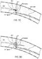
- FIG. 3Cwhere a plurality of ribs 310 are disposed on a distal end 320 of a guidewire 300.
- the ribs 310are configured to flare out, as shown in FIG. 3D .
- the ribs 310are kept under tension, for example by using a restraining sleeve (not shown), by twisting the ribs 310, by exerting a stretching or pulling force on the proximal ends of the ribs 310, etc.
- the guidewire 300, with the ribs 310 in a collapsed stateis advanced into the occlusion.
- the ribs 310flare open.
- the ribs 310comprise electrode areas 330 adjacent to insulator areas 340, as shown in the cross-sectional view of FIG. 3E .
- the insulator areas 340are on the outside and the electrode areas 330 are on the inside of the basket-like configuration.
- This configurationadvantageously aids in directing radiofrequency energy inside the basket-like configuration while simultaneously providing protection to the surrounding tissue.
- the placement of the electrode areas 330 and insulator areas 340may be varied.
- a capture devicemay be configured to comprise one or more electrode areas for use as return electrodes. Examples of capture devices are disclosed in the co-pending US Patent Application Serial Number 12/150,111 by the same inventors, which is incorporated herein in its entirety.
- a centering balloon cathetercan be utilized along with the guidewire to center the guidewire within the vessel prior to energizing the system.
- a centering balloon cathetercan be utilized along with the guidewire to center the guidewire within the vessel prior to energizing the system.
- the cathetercomprises a means for removing or withdrawing debris resulting from the RF ablation.
- a mechanismcould be provided to capture and retrieve the debris, or a suction device could be provided to actively remove the debris near the ablation area. Examples of such embolic protection mechanisms are disclosed in the above referenced co-pending US Patent Application Serial Number 11/706,041 .
- FIG. 4shows an exemplary embodiment of a longitudinal member 400 comprising an embolic protection mechanism 410.
- the embolic protection mechanism 410comprises a filter, mesh, net, or similar element, for capturing and retrieving ablation debris.
- the embolic protectionmay comprise a balloon for occluding the vessel and preventing the debris from circulating, and for subsequent aspiration of the debris through a longitudinal member.
- a sheathmay also be configured to be or to include a debris capture and retrieval mechanism or a suction device.
- a longitudinal membermay be retracted, and the remaining sheath may be used as a capture and retrieval mechanism or a suction device to remove ablation debris.
- the longitudinal membercomprises an ablating wire housed in the lumen of a dilating catheter. Upon ablation, the ablating wire may be retracted and the dilating catheter may be used to remove the debris.
- the systemcomprises a separate catheter to provide suction, or otherwise capture and remove the debris from the ablation site.
- the devicemay be coupled to an electrocardiogram (EKG) machine to aid in timing energy emissions.
- EKGelectrocardiogram
- the rate of blood flow through the coronary arteriestypically varies during the cardiac cycle.
- flow through the arteriesis generally lower than during diastole.
- energy emissionis timed during diastole, for example using an algorithm to detect the R-wave of an EKG, and energy emission is timed to occur when flow is highest, thereby maximizing the cooling effect provided by blood flow and consequently minimizing the heat exposure to the vessel.
- coronary artery dimensionscan vary during the cardiac cycle and energy emission can similarly be timed to take advantage of this fact.
- the devicemay be configured to perform an imaging function, such as intravascular ultrasound or optical coherence tomography (OCT).
- OCToptical coherence tomography
- thismay be accomplished by adding a piezoelectric crystal to a longitudinal member of the device, wherein the piezoelectric crystal may be energized to transmit or receive ultrasonic waves.
- an imaging coremay be inserted into a longitudinal member of the device (e.g., in the case of a dilating catheter) and operated to transmit and receive ultrasonic waves.
- an optical fibermay be used for performing OCT imaging.
- the devicecomprises a mechanism for detecting or estimating the distance between the electrodes, and for decreasing the amount of delivered RF energy as the distance between the electrodes decreases, thereby minimizing potential RF injury to the vessel wall.
- the deviceis an ablation catheter comprising a longitudinal member having a distal end, a proximal end, and a guidewire shaft there-between comprising a guidewire lumen.
- the longitudinal memberis a dilating catheter and is structurally configured along at least part of the length of the catheter to enable advancement or alignment of the longitudinal member through a narrow diameter blood vessel or occlusion. Advancement is achieved, for example, by turning or twisting the longitudinal member.
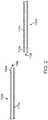
- FIGS. 5A-5Cshow such an embodiment of the present invention.
- the longitudinal member 500may comprise a helical exterior 501 that advances through the vessel and dilates the vessel as the member is being twisted or rotated.
- Helical exterior 501comprises a plurality of grooves 502 carved into the outer body of the longitudinal member 500.
- the distal tip of longitudinal member 500optionally comprises a radiopaque marker 510.
- An electrode 520is located at or near the distal end of the catheter.
- FIG. 5Bthe cross section of which is shown in FIG. 5C .
- the longitudinal member 550may comprise a plurality of wires 551 and 552 wound around a liner 565. In one embodiment, the wires 551 and 552 comprise at least two different diameters. Longitudinal member 550 optionally terminates at a marker 570.
- An electrode 580is located at or near the distal end of the longitudinal member 550.
- the ablation catheteradditionally and optionally comprises conductive wires for transmitting energy between the electrode and an external energy source.
- the plurality of wiresmay be configured to act as the electrode or conductive wires.
- the cathetercomprises an insulating sheath 560 which is optionally retractable.
- the guidewires and electrodesmay be made from any one or more suitable materials as is commonly known in the art. Examples of such suitable materials include stainless steel, Nitinol, Elgiloy, platinum, iridium, tantalum, titanium, cobalt, chromium, tungsten, or any combinations thereof.
- one or more of the guidewiresmay be made of a polymer, with an electrically conductive core for transmitting electrical energy to the respective electrodes.
- Additional embodiments disclosed herecomprise of methods, systems, and devices to recanalize an occluded body vessel by penetrating the distal cap of the occlusion without approaching the distal cap from the retrograde direction through an intercoronary channel; thereafter, RF energy may be delivered in a biopolar arrangement between two longitudinal members as described above.
- the devicecomprises a first longitudinal member 610 and a second longitudinal member 620.
- the first longitudinal member 610comprises a first distal end 611 and a first proximal end 612.
- the first distal end 611may be configured to penetrate the proximal cap PC of an occlusion such that the first longitudinal member 610 may advance at least partly into the occlusion body OB from the proximal true lumen PTL in an antegrade fashion.
- the second longitudinal member 620comprises a second distal end 621 and a second proximal end 622.
- the second distal end 621may be configured to penetrate a portion of the occluded body vessel BDL such as the proximal cap PC or a portion of the subintimal space SIS.
- the second longitudinal member 620may advance at least partly into the occlusion body OB from the proximal true lumen PTL in an antegrade fashion. Alternatively, the second longitudinal member 620 may advance through the subintimal space SIS without traversing through the occlusion body OB.
- the second distal end 621may be further configured to be capable of being redirected.
- the second distal end 621may be redirected once the second longitudinal member 620 has at least traversed the length of the occlusion body OB and/or otherwise has entered the distal true lumen DTL. Whereupon redirection, the second distal end 621 may be positioned such that the second distal end 621 may be configured to penetrate the distal cap DC of the occlusion.
- the redirection of the second distal end 621may be accomplished through various methods.
- the devicemay comprise one or more strings (not shown) attached to the second distal end 621, wherein a user may manipulate the strings to mechanically redirect the second distal end 621.
- a portion of the second distal end 621may be constructed of various shape memory alloys and the second distal end 621 may be redirected by exploiting properties of the shape memory alloys.
- a portion of the second distal end 621may comprise heat memory alloys, wherein the second distal end 621 is configured to be redirected when it is sufficiently exposed to an elevated temperature environment such as the human body.
- the second distal end 621may be pre-shaped or may comprise magnetic shape memory alloy, electric shape memory alloy, etc.
- the second distal end 621may comprise one or more shape memory alloy types.
- the second distal end 621may comprise one or more shape memory alloy types and may also be subject to mechanical manipulation, such as by strings as described above.
- RF energymay be delivered through the first and the second longitudinal members.
- the first and the second distal ends 611 and 621may each comprise at least one electrode such that controlled energy deployment is achieved using a bipolar arrangement of the electrodes as described above.
- the method of recanalization using one aspect of the present embodimentsis shown schematically as a flow diagram in FIG. 7 with reference to FIGS. 8A-8F .
- the first distal end 611 of the first longitudinal member 610penetrates the proximal cap PC and at least a portion of the first longitudinal member 610 is advanced into the occlusion body OB in an antegrade fashion as seen in FIG. 8A .
- the second distal end 621 of the second longitudinal member 620penetrates a portion of the occluded body vessel BDL. Thereafter, at least a portion of the second longitudinal member 620 is advanced into a body region of, or close to the occlusion. As seen in FIG. 8B , the second distal end 621 may penetrate the proximal cap PC and the second longitudinal member 620 may advance through a portion of the occlusion body OB. Alternatively, the second distal end 621 may penetrate a site within the proximal true lumen PTL such as the subintimal space SIS near the proximal cap PC. Thereafter, as seen in FIG. 8B the second longitudinal member 620 may then enter and advance through the subintimal space SIS.
- the second longitudinal member 620may traverse at least the length of the occlusion body OB and it is advanced into the distal true lumen DTL through the subintimal space SIS.
- the second longitudinal member 620may be advanced in an antegrade fashion through a portion of the subintimal space SIS without traversing a portion of the occlusion body OB.
- the second distal end 621is redirected such that the second distal end 621 is configured to be capable of penetrating the distal cap DC.
- a first portion 623 of the second longitudinal member 620 comprising the second distal end 621is re-configured such that the first portion 623 is at an angle with respect to a second portion 624 of the second longitudinal member 620.
- the anglemay be configured as any angle wherein the second distal end 621 is positioned such that it is capable of penetrating the distal cap DC.
- the second distal tip 621penetrates the distal cap DC and at least a portion of the second longitudinal member 620 is advanced into the occlusion body OB in a retrograde fashion.
- the second longitudinal member 620is advanced into the occlusion body OB until it is positioned at or near the first distal end 611 of the first longitudinal member 610.
- the electrodes disposed on the first and the second distal ends 611 and 621may be positioned substantially towards each other.
- RF treatmentmay be initiated to create a recanalization channel.
- the second distal end 621 of the second longitudinal member 620may not be required for the second distal end 621 of the second longitudinal member 620 to penetrate the distal cap DC and to advance into the occlusion body OB in a retrograde fashion. In fact, it may be sufficient for the second distal end 621 and the first distal end 611 to be positioned within proximity where the radio frequency spark may cross from the active electrode disposed on one longitudinal member to the return electrode disposed on the other longitudinal member to achieve ablation.
- the second distal end 621 of the second longitudinal member 620may be positioned within the distal true lumen DTL, and the first distal end 611 of the first longitudinal member 610 may be positioned within the occlusion body OB, RF energy may then be delivered between the active and return electrodes disposed on the two distal ends to ablate a portion of the occlusion body OB in between the two distal ends.
- first and the second longitudinal membersmay be coupled by using one or more coupling elements (not shown) such that the two longitudinal members may create a recanalization channel between the proximal and distal ends of the occlusion body OB.
- coupling elementsnot shown
- the controlled antegrade and retrograde tracking (CART) techniques disclosed in the co-pending US Patent Application Serial Number 11/706,041 as referenced abovemay be used to facilitate the coupling.
- the coupling elementmay be configured to securely lock the first longitudinal element and the second longitudinal element to prevent separation during the guidewire placement procedure. Additionally and optionally, the coupling element may be configured to provide quick and easy detachment of the two longitudinal elements.
- the coupling elementmay comprise a screw mechanism.
- the coupling elementmay comprise a male portion disposed on the distal end of either the first or the second longitudinal member, and a female portion disposed on the distal end of the other longitudinal element, wherein the male portion is configured to be inserted into the female portion.
- the male portioncan be spring loaded to more securely attach inside the female portion.
- the coupling elementmay comprise a flaring rib mechanism in which one longitudinal element is snared by the other longitudinal element as described in the co-pending US Patent Application Serial Number 12/150,111 as referenced above.
- couplingmay be achieved by other means of coupling, connecting, or extending longitudinal members such as the use of magnets where the distal ends of the first and the second longitudinal members comprise magnets of opposite polarity.
- the coupled longitudinal membersadvance in either the antegrade or retrograde direction through the occlusion body OB until one longitudinal member traverses the occlusion body OB and a portion of it is positioned within the true distal lumen DTL.
- the first longitudinal member 610is positioned in an antegrade direction through the occlusion body OB. Thereafter, the first longitudinal member 610 and the second longitudinal member 620 may be decoupled, and the second longitudinal member 620 may be removed from the body.
- a recanalization channelhas been created over the wire recanalization techniques that are well known in the art can be performed either in the antegrade fashion or the retrograde fashion to recanalize the occluded body vessel BDL, for example, a balloon catheter for performing an interventional procedure.
- the second longitudinal membermay be delivered into the distal true lumen DTL from an antegrade direction using a delivery element.
- the second longitudinal element 820may be inserted into a delivery lumen of the delivery element 830.
- the delivery element 830may be a delivery catheter, mircocatheter, a dilating catheter, a guiding catheter, or the like.
- the delivery element 830then traverses the length of the occlusion body OB as described above. Thereupon reaching the distal true lumen DTL, as seen in FIG. 9B the second longitudinal member 820 is advanced through the delivery lumen.
- the distal end of the second longitudinal member 820may be pre-shaped such that the distal end 821 may not need to be redirected in order to penetrate the distal cap DC.
- the degree of redirection needed to position the distal end 821 of the second longitudinal member 820may be decreased in comparison to an embodiment where the second longitudinal member 820 is inserted into the body without a delivery element 830.
- At least a portion of the pre-shaped distal end 821may comprise Nitinol or other shape memory alloys such that the second longitudinal member 820 may be compressed when loaded into the delivery element 830. Upon reaching the distal true lumen DTL, the compression may be relieved when the second longitudinal member 820 is advanced through the delivery element 830 and the distal end 831 may then assume the pre-shaped configuration.
- the delivery element 830may further comprise an aspiration element (not shown) configured to remove debris products, such as debris produced by the RF treatment.
- the aspiration elementcomprises an aspiration port disposed on the distal end of the delivery element 830, and an aspiration lumen connecting the aspiration port and the aspiration source.
- the debris productsmay be removed through the aspiration port through pressure differentials generated between the aspiration port and the aspiration source, such that debris products may be transmitted through the aspiration port and are thereby removed.
- the delivery lumenmay be configured as the aspiration lumen, in another embodiment, the aspiration lumen may be a substantially independent lumen disposed within the delivery element 830.
- the distal ends of the first longitudinal member, the second longitudinal member, and/or the delivery elementcan assume any configurations that enable the first and/or the second distal ends to penetrate the distal cap DC, the subintimal space SIS, and/or any other region of the occluded blood vessel BDL.
- one or both distal ends of the longitudinal members and/or the distal end of the delivery elementmay be configured as deflectable tips.
- the distal ends of the longitudinal members or the delivery elementmay be configured as bevel tips.
- the distal ends of the longitudinal members or the delivery elementmay be configured as heated tips, whereby the thermal energy radiating from the heated tips may ease the penetration and/or the advancement of the longitudinal members.
- a cross-sectional area of the longitudinal members and/or the delivery elementmay be configured to progressively increase from the distal end towards the proximal end.
- the tapered configurationmay be advantageous in that the narrow distal end may be configured to effectively traverse through the vascular matrix and to penetrate the occlusion and/or the subintimal space SIS, whereas the larger proximal end is configured to allow a user to manipulate the longitudinal members during the operation.
- a cross-sectional area of the longitudinal membersmay be configured to be substantially unchanged throughout the lengths of the longitudinal members.
- the flexibility of the longitudinal membersmay vary over their respective lengths.
- the distal endsmay be substantially flexible, and the flexibility progressively decreases towards the proximal ends.
- the longitudinal members of the present embodimentsmay comprise at least a layer of structural polymer over the core wire. Additionally and optionally, an outer surface of the longitudinal members may be coated with hydrophilic coating for ease of navigation through tortuous passageways.
- both the first and the second longitudinal members 910 and 920may be advanced in an antegrade fashion into the occlusion body OB.
- the first and the second distal ends 911 and 921 of the longitudinal memberscan be configured to be redirected such that the first distal end 911 is directed substantially towards the second distal end 921 and/or the second distal end 921 may be directed substantially towards the first distal end 911.
- the redirectionmay be accomplished through various methods described above. This approach minimizes the potential of the vessel wall becoming perforated or injured, as may otherwise occur in a conventional bipolar RF treatment approach.
- the tissue that is ablated by the RF treatmenti.e., the occlusion
- the tissue that is ablated by the RF treatmentis well contained between the electrodes. This also allows the user to localize the treatment to the occlusion while minimizing vessel wall damage.
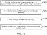
- FIG. 11The sequence of the recanalization treatment steps where both the first and the second distal ends of two longitudinal members are redirected are illustrated in FIG. 11 as a flow diagram.
- the first and the second longitudinal members 910 and 920are advanced through the proximal cap PC into the occlusion body OB in an antegrade fashion.
- the longitudinal membersmay be advanced as deep into the occlusion body as possible to minimize the distance between the electrodes and, consequently, minimize the length of the ablation zone. Confirmation that the electrodes are in an appropriate position can be generated by impedance measurements and/or by using any of the standard imaging techniques employed during interventional procedures, such as fluoroscopy or intravascular ultrasound (IVUS), in which transducers are placed on the distal ends of one or both of the longitudinal member.
- the calcified occlusion bodyWhen using tissue impedance measurements, the calcified occlusion body generally exhibits significantly higher impedance than the vessel wall. If an impedance measurement indicates a low impedance value, it is likely that one or both longitudinal members are in contact with the vessel wall, and appropriate repositioning may be warranted.
- the first and/or the second longitudinal membermay be advanced through the subintimal space SIS and then entered into the occlusion body OB in an antegrade fashion.
- one or both of the distal ends 911 and 921may be redirected such that the electrodes disposed on the first and the second distal ends are positioned towards each other. Furthermore, it is desirable that the electrodes are in contact with the occlusion body OB but are not in contact with the vessel wall to prevent or minimize damage to the vessel wall.
- the RF treatmentmay be initiated.
- first and/or the second longitudinal membersmay be delivered into the occlusion body OB wherein the distal ends are pre-shaped such that redirection of one or more of the distal ends is reduced or not required in order for the distal ends to be substantially positioned towards each other. Additionally, the first and/or the second longitudinal members may be delivered into the occlusion body OB using one or more delivery elements as described above and illustrated in FIGS. 9A-9B .
- one of the longitudinal membersmay be withdrawn and the other longitudinal member may be advanced through the occlusion body OB and standard interventional procedures as described above may be performed.
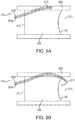
- the present embodimentsfurther contemplate a centering balloon catheter system configured to position one or more longitudinal members within the body vessel and reduce the likelihood of the longitudinal members slipping away from a portion of the occlusion.
- the balloon catheter systemcomprises an inflatable balloon 1120 disposed on a balloon catheter 1110, wherein the balloon may be inflated with a biocompatible fluid such as a gas (CO 2 ) or a liquid such as saline or contrast agents.
- the inflation mediummay be delivered through a separate inflation lumen (not shown).
- the balloon 1120upon inflation, may be configured to occupy substantially the entire interior of a vessel such that the balloon catheter system may be substantially fixed in place within a body vessel.
- the balloon catheter systemmay comprise a delivery catheter 1130 disposed within the balloon catheter 1110.
- the delivery catheter 1130may be configured to deliver one or more longitudinal members to the occlusion body OB.
- the delivery catheter 1230may comprise helical grooves 1231 and the balloon catheter 1210 comprising an inflatable balloon 1220 may comprise receiving grooves 1211 configured to receive the helical grooves 1231 disposed on the delivery catheter 1230.
- the receiving grooves 1211are configured to allow the helical grooves 1231 to rotate within the balloon catheter 1210 without moving the balloon catheter 1210.
- the delivery catheter 1230may be advanced within the balloon catheter 1210 by twisting or otherwise turning the delivery catheter 1230 while the balloon catheter 1210 maintains a substantially fixed position within the body vessel.
- the delivery cathetermay comprise a single lumen as seen or it may comprise multiple lumens (not shown).
- the multi-lumen configurationmay be advantageous by facilitating insertion and/or removal of various apparatus during the operation.
- the multi-lumen configurationmay be advantageous such that one or more of the lumens may be configured as suction lumens, wherein suction force may be applied through the suction lumens to stabilize the delivery catheter upon the occlusion body OB as described in co-pending U.S. Application Serial Number 13/042,411 by the same inventors, which is incorporated herein in its entirety.
- the lumensmay assume various positional configurations relative to another lumen within the catheter.
- the delivery cathetermay comprise two or more lumens configured in a non-coaxial manner.
- the delivery cathetermay comprise two or more lumens configured in a coaxial manner. It is further contemplated that the lumens may assume various shape and position configurations within the catheter.
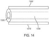
- a longitudinal member with a lumen 1300comprises a distal opening 1320, a proximal opening (not shown), and an elongated body 1330 disposed in- between.
- the longitudinal membermay be coated with an insluator 1310, such as Teflon, ceramic, polyimide, parylene, or other suitable materials. Examples of methods which could be employed for coating may include spraying, dipping, vapor deposition, or plasma deposition.
- the proximal openingmay be connected to a fluid source and the distal opening 1320 of the lumen is configured to deliver at least one fluid to the treatment region of the blood vessel, wherein the fluid may be transmitted from the fluid source through the elongated body lumen 1330.
- the longitudinal membermay comprise an injection port (not shown) that traverses the coating 1310 to connect a fluid source with the elongated body 1330.
- the elongated body 1330may be coated with materials, such as hydrophobic materials that are configured to prevent fluids from exiting the elongated body.
- the treatment fluidmay be liquids and/or gases such as saline, compressed air, various drugs, or the like.
- the fluid delivered to the treatment region of the blood vesselmay be used as coolants to control the temperature of the treatment region during the ablation procedure. Additionally and optionally, the fluid delivered to the treatment region may be used to weaken and/or break up a portion of the occlusion.
- compressed airmay be delivered into the occlusion during the advancement of the longitudinal member.
- the compressed gasmay be used to enlarge or expand a space in the occlusion already created by the penetration of the occlusion and/or by the ablation.
- the expanded space created by the compressed airmay aid in further advancement of the longitudinal member.
- the fluid delivered to the treatment regionmay serve other functions such as delivering therapeutic agents to the treatment regions and the like.
- the fluid delivered to the treatment site through the longitudinal membermay be a conductive fluid such as isotonic saline.
- the fluidmay immerse a portion of the target site such that the active electrode disposed on another longitudinal member may generate a current density that is sufficiently high to cause sparks crossing over to the fluid immersed target site.
- the fluidmay acts as an energy sink, receiving the energy delivered from the active electrode. It is envisioned that the energy as applied from the active electrode may be sufficient to vaporize the fluid such that plasma may be formed to cause disintegration or breakdown of the occlusion in contact with the plasma.
- the guidewiremay be advanced at least partly into the occlusion; thereafter, a first fluid, such as compressed air may be delivered into the occlusion to create or expand a space. Thereafter, a second fluid, such as isotonic saline may be delivered into the space created by the first fluid.
- a first fluidsuch as compressed air
- a second fluidsuch as isotonic saline
- the isotonic salinemay serve as a conductive fluid that receives radiofrequency energy as delivered by an active electrode. The saline may then be vaporized by the radiofrequency energy to create plasma that causes disintegration of a portion of the occlusion that is in contact with the plasma.
- one or more longitudinal members of the recanalization systems of the present inventioncomprise one or more ultrasound transducers, instead of or in addition to RF electrodes.
- the ultrasound transducersprovide ultrasound energy for ablating an occlusion.
- the antegrade and/or the retrograde longitudinal membersmay comprise ultrasound transducers and ablate the lesion from an antegrade as well as a retrograde direction.
- Other energy modalitiescould include microwave and laser.
- the combined antegrade and retrograde energy delivery techniques described abovecould also be used as an adjunct technique to crossing CTOs in combination with using conventional methods.
- the techniquecould be used to sufficiently soften or weaken the occlusion, thereby allowing a guidewire or catheter to cross the occlusion.
Landscapes
- Health & Medical Sciences (AREA)
- Life Sciences & Earth Sciences (AREA)
- Surgery (AREA)
- Engineering & Computer Science (AREA)
- Veterinary Medicine (AREA)
- General Health & Medical Sciences (AREA)
- Biomedical Technology (AREA)
- Heart & Thoracic Surgery (AREA)
- Public Health (AREA)
- Animal Behavior & Ethology (AREA)
- Physics & Mathematics (AREA)
- Medical Informatics (AREA)
- Molecular Biology (AREA)
- Nuclear Medicine, Radiotherapy & Molecular Imaging (AREA)
- Otolaryngology (AREA)
- Electromagnetism (AREA)
- Anesthesiology (AREA)
- Hematology (AREA)
- Biophysics (AREA)
- Pathology (AREA)
- Radiology & Medical Imaging (AREA)
- Vascular Medicine (AREA)
- Cardiology (AREA)
- Plasma & Fusion (AREA)
- Optics & Photonics (AREA)
- Pulmonology (AREA)
- Gynecology & Obstetrics (AREA)
- Oral & Maxillofacial Surgery (AREA)
- Child & Adolescent Psychology (AREA)
- Surgical Instruments (AREA)
- Laser Surgery Devices (AREA)
- Media Introduction/Drainage Providing Device (AREA)
Abstract
Description
- This application claims priority from United States Application Ser. No.
12/753,844, filed April 2, 2010 12/680,500 PCT Application No. PCT/US2008/077403, filed September 23, 2008 , which claims the priority benefit ofU.S. Provisional Application No. 60/975,473, filed September 27, 2007 12/753,844 U.S. Provisional Application Ser. No. 61/298,547, filed on January 26, 2010 - This invention relates generally to dealing with occlusions of the lumen and more specifically to apparatus and methods for crossing severe or total chronic occlusions of lumens in the body using radiofrequency energy.
- Chronic total occlusion (CTO) is the complete blockage of a vessel and may have serious consequences if not treated in a timely fashion. The blockage could be due to atheromatous plaque or old thrombus. One of the common procedures for treating CTOs of the coronary arteries is percutaneous transluminal coronary angioplasty (PTCA). During a PTCA procedure, a small incision is typically made in the groin. A guiding catheter over a guidewire is introduced into the femoral artery and advanced to the occlusion. At times, with gentle maneuvering, the guidewire is able to cross the occlusion. A balloon-tipped angioplasty catheter is then advanced over the guidewire to the occlusion. The balloon is inflated, separating or fracturing the atheroma. Often times, a stent is subsequently or simultaneously deployed. Some of the common steps involved in the PTCA procedure for CTOs are the simultaneous injection of a contrast agent in the contra-lateral vessel, securing backup force or stabilization for a guidewire (which could invoke additional personnel to handle the catheter), puncturing the plaque, drilling or rotating the guidewire to push it through the dense plaque, etc. Because of the stiff resistance sometimes offered by dense plaque, one could be forced to use stiff wires. Occasionally, the wires could puncture the vessel wall calling for remedial measures.
- The most common percutaneous coronary intervention (PCI) failure mode for CTOs is inability to successfully pass a guidewire across the lesion into the true lumen of the distal vessel. To date, there is no consensus on how best to treat CTO after attempts with conventional guidewires have failed. Different strategies for CTOs have been developed including the side branch technique, the parallel wire technique, and the IVUS guided technique. Mechanical and energy based devices have also been proposed for passing guidewires through hard calcified occlusions, such as mechanical cutting or oscillation and laser or ultrasound or radiofrequency (RF) energy ablation. Each of these devices works by strictly utilizing an antegrade approach and locally applying energy (typically in the form of heat) at the tip of the guidewire or catheter device in order to create a channel and hopefully enter the distal true lumen.
- RF energy is widely used to coagulate, cut or ablate tissue. In both modalities, monopolar and bipolar, conductive electrodes contact the tissue to be treated. In the monopolar mode, the active electrode is placed in contact with the tissue to be treated and a return electrode with a large surface area is located on the patient at a distance from the active electrode. In the bipolar mode, the active and return electrodes are in close proximity to each other bracketing the tissue to be treated. Sometimes an array of electrodes is used to provide better control over the depth of penetration of the RF field and hence control over the temperatures to which the tissue is heated. There are many disadvantages with each mode. For example, in the monopolar arrangement, because of the large physical separation between the electrodes there are frequent reports of local burning at the electrode sites. This would clearly be undesirable where one of the electrodes will be inside a blood vessel. The other serious issue is the likelihood of forming blood clots. The tissue that is in contact with the electrodes can be coagulated or ablated. In the case of the electrodes being present inside a blood vessel, the formation of dangerous blood clots would obviously be undesirable.
- In an attempt to overcome the issues described above, various device and electrode configurations are described in the following patents.
US Patent Numbers 5,366,443 and5,419,767 describe the use of RF electrodes on a catheter to cross a lesion. These patents describe a bipolar electrode assembly at the distal tip of a catheter that is in contact with the occlusion, and patentees state that application of RF energy ablates the occlusion and renders the occlusion susceptible for the guidewire to penetrate. This method has the drawback that careful tracking of the occlusion and the ablation process is necessary to avoid trauma to the vessel walls or healthy tissue, since the possibility of short-circuiting of current through healthy tissue instead of the occlusion is high.US Patent Number 5,419,767 overcomes this limitation to a certain extent through the use of a multiple electrode array. However, this device requires a channel to be pre-created through the occlusion so that the device can be passed through a guidewire traversing this channel, which is not always easy. US Patent Number 5,514,128 to Hillsman et al. describes a laser catheter device that enables ablation of an occlusion in the vasculature. This system has similar drawbacks to the ones described above - need for a guidance system, potential for healthy tissue to be ablated, complexity (and hence cost) of the device, etc.- One major problem with the existing devices is the potential for the ablation energy to damage the walls of the vasculature, in the absence of a mechanism to track the orientation and position of the energy delivery member. Several devices exist in the prior art that address the issue of tracking and steering of the energy delivery element.
US Patent Number 6,911,026 to Hall et al. describes a magnetic steering and guidance system to direct an ablation device that delivers RF energy at the tip in a unipolar configuration where the return electrode is placed externally in contact with the body or in a bipolar configuration where the return electrode is a ring surrounding the central wire electrode. US Patent Number 6,416,523 to Lafontaine discusses a mechanical cutting device where the guidance is provided by measuring impedance of the tissue in contact. The guidance system senses the difference in impedance between the stenotic tissue and the vessel wall and directs the cutting element to the occlusion.- However, none of these alternate strategies have provided satisfactory results for the most challenging of the CTOs. In case of hard calcified occlusions, the revascularization procedure can be tedious and time consuming. Therefore, there is a need for improved methods of ablating or disrupting the occlusive material that are safe, efficacious and fast. It would be beneficial to have alternate techniques and devices that would recanalize a CTO without the shortcomings of the current techniques.
- CTOs that are hard to recanalize, either because of the tortuous anatomy of the diseased vessel, or because the proximal end of the stenosis is too hard for the guide wire to penetrate, or other characteristics of the CTO that would make the standard procedure vulnerable to failure would benefit from newer approaches to recanalize CTOs. Recently a combined antegrade-retrograde approach has been proposed for recanalizing chronic occlusions (
US Application Serial Number 11/706,041 ). The method disclosed in the co- pending application would benefit from the use of energy for crossing CTOs. - Various methods and devices are provided to overcome some of the commonly encountered problems in treating chronic total occlusions. One aspect of this invention is to provide a method and systems for successfully recanalizing an occluded vessel by advancing, in combination, guidewires in an antegrade and retrograde fashion to the occlusion and applying RF energy between the proximal and distal ends of the occlusion. The RF energy application across the occlusion is accomplished using a bipolar arrangement, where one electrode is located on the antegrade guidewire and the other electrode that makes up the bipolar arrangement is located on the retrograde guidewire. In one aspect, the present invention discloses a method of recanalizing an occluded vessel comprising advancing in an antegrade fashion a first longitudinal member through a proximal end of an occlusion, advancing in a retrograde fashion a second longitudinal member through a distal end of the occlusion, applying RF energy between the distal ends of the antegrade and retrograde guidewires, ablating the tissue locally, and creating a channel through which a guidewire could be advanced. In another embodiment, the retrograde guidewire could have a deployable capture mechanism at its distal end and upon deployment could snare the antegrade guidewire.
- In another aspect, this invention relates to a catheter assembly for recanalizing an occluded vessel comprising an antegrade longitudinal member with a distal end containing an RF electrode and a retrograde longitudinal member with a distal end containing a second RF electrode; and the proximal end of the catheter assembly connected to an RF generator. Additionally, a temperature measuring element could be disposed on the distal ends of the antegrade or retrograde longitudinal member. The RF generator could also be programmed to treat the tissue for a pre-set time or until a set condition has been reached. One such condition could be till the occlusion has reached a pre-determined temperature. Another condition could be the impedance of the occlusion.
- In another aspect, the invention is a kit for recanalizing occluded vessels comprising one or more of the following: an antegrade guidewire, a retrograde guidewire, a dilating device, a capture device and an injection catheter, wherein at least one of these devices contains at least one electrode. Additionally, the proximal ends of this device are configured to be coupled with an RF generator.
- In another aspect, a system for recanalizing occluded vessels may comprise two antegrade longitudinal members, wherein at least one longitudinal member may comprise a distal end that is capable of being redirected. The redirected distal end may substantially position in a retrograde fashion towards the occlusion. Alternatively, the redirected distal end may be substantially positioned towards the distal end of another longitudinal member. In another aspect, at least one longitudinal member may comprise an interior lumen configured to deliver a fluid to the occlusion.
- In yet another aspect, the invention relates to a catheter positioning system with a balloon catheter comprising an inflatable balloon, a delivery catheter disposed within the balloon catheter, wherein upon inflation of the balloon, a position of the balloon catheter is substantially fixed, and wherein the delivery catheter is configured to advance through the balloon catheter without substantially altering the position of the balloon catheter.
- Other aspects of the invention include methods corresponding to the devices and systems described above.
- The invention has other advantages and features which will be more readily apparent from the following detailed description of the invention and the appended claims, when taken in conjunction with the accompanying drawings, in which:
FIG. 1 is a schematic showing an RF generator connected to the longitudinal members.FIG. 2 shows the features of the longitudinal members.FIGS. 2A-2B show various embodiments of longitudinal members comprising insulators.FIGS. 3A and3B show the steps involved in recanalizing a CTO using bipolar RF and combined antegrade and retrograde approach.FIGS. 3C-3E show embodiments of electrodes configured to expand outwardly.FIG. 4 shows an example embodiment of a longitudinal member comprising an embolic protection mechanism.FIGS. 5A-5C show a longitudinal member structurally configured along at least part of the length of the catheter to enable advancement or alignment of the longitudinal member through a narrow diameter blood vessel or occlusion.FIG. 6 shows one embodiment of the recanalization system comprising a longitudinal member that is capable of being redirected.FIG. 7 shows a flow diagram of various steps involved in performing the recanalization of the body vessel according to the present embodiments.FIGS. 8A-8F show various stages of recanalization of the body vessel according to the present embodiments.FIGS. 9A-9B show one embodiment of the recanalization system comprising a delivery element.FIG. 10 shows one embodiment of the recanalization system utilizing radio frequency energy.FIG. 11 shows a flow diagram of various steps involved in performing the recanalization of the body vessel utilizing radio frequency energy.FIG. 12 shows one embodiment of the centering balloon catheter system.FIG. 13A-13B show one embodiment of the centering balloon catheter system comprising helical groves.FIG. 14 shows one embodiment of longitudinal member comprising an lumen.- Although the detailed description contains many specifics, these should not be construed as limiting the scope of the invention but merely as illustrating different examples and aspects of the invention. It should be appreciated that the scope of the invention includes other embodiments not discussed herein. Various other modifications, changes and variations which will be apparent to those skilled in the art may be made in the arrangement, operation and details of the method and apparatus of the present invention disclosed herein without departing from the spirit and scope of the invention as described here.
- The present embodiments combine the use of RF energy delivered through antegrade and retrograde members for recanalizing occluded lumens, particularly chronic total occlusions. The methods and systems described herein recanalize difficult to cross occlusions by taking advantage of an antegrade and retrograde approach to establish a bipolar electrode arrangement across the occlusion. This approach minimizes the potential of the vessel wall becoming perforated or injured, as may otherwise occur in a conventional bipolar RF treatment approach, where both RF electrodes are on the same side of the occlusion. Because the electrodes are distributed on opposite sides of the occlusion, the tissue that is ablated by the RF treatment (i.e., the occlusion) is well contained between the electrodes. This also allows the user to localize the treatment to the occlusion.
- As disclosed in the co-pending
US Patent Application Serial Number 11/706,041 by the same inventors, which is incorporated herein in its entirety, in the controlled antegrade and retrograde tracking (CART) technique the retrograde approach takes advantage of an intercoronary channel. Such a channel may be an epicardial channel, an inter-atrial channel, an intra-septal channel (also referred to as septal collateral), or a bypass graft. The basic concept of the CART technique is to create a channel through an occlusion, preferably with limited dissections, by approaching the occlusion both antegradely and retrogradely. - While the combined antegrade and retrograde approach has been effective in crossing difficult to cross lesions, it has been observed that using energy, for example RF energy, to ablate or alter the tissue in a controlled fashion is beneficial in crossing hard to cross lesions. Such controlled energy deployment is achieved using a bipolar arrangement of the electrodes, where one electrode is located on the antegrade element and the other electrode that constitutes the bipolar arrangement is located on the retrograde element. These electrodes can also be referred to as the return and active electrodes. They are also referred to as the anode and cathode, respectively. The electrodes could also be arranged in an array (multiple electrodes), where the electrode arrangement provides better control over the depth of penetration of the RF field and thereby provides the ability to control the tissue temperature.
FIG. 1 shows a system for recanalizing occluded vessels using RF energy. The system compriseslongitudinal members FIG. 1 ,longitudinal member 100a serves as an antegrade member andlongitudinal member 100b serves as a retrograde member. An RF generator10 (also referred to as a controller) serves as the source of RF energy to be provided tolongitudinal members Longitudinal members longitudinal members longitudinal member - To provide RF energy from the
RF generator 10 to theguidewires pigtail 20 connects at its proximal end to theRF generator 10 and terminates at its distal end in aconnector 30.Connector 30 is a standard connector that couples the input and output signals of theRF generator 10 to theguidewires - One embodiment of the connector would be a locking tool or torque device which can be placed over the guidewire. In such a configuration, the locking tool or torque device is configured to make electrical contact with a portion of the guidewire (such as the guidewire corewire) that conducts radiofrequency energy to, or from, the one or more electrodes disposed on the guidewire. In such a configuration, the locking tool or torque device would also be configured to connect to a radiofrequency generator, thereby electrically connecting the generator to the guidewire and electrodes. Means of locking the connector to the guidewire may include compressible prongs, screws, sliding rings, or other mechanisms commonly utilized in torque devices.
- Guidewires100a and100b are configured to have sufficient torsional rigidity and longitudinal flexibility to advance through an occlusion, and to align their electrodes in a direction away from the vessel wall, towards the other guidewire, or any combination thereof.
- As shown in
FIG. 2 , the antegrade andretrograde guidewires conductive electrodes electrodes respective guidewires - Conductive wires (not shown) connect the
electrodes connector 30 to deliver RF energy from theRF generator 10 to theelectrodes non-conductive layers non-conductive layers FIG. 2A shows a cross-sectional view of a guidewire comprising an electrode and an insulator, in accordance with an embodiment of the present invention. Aguidewire 200 comprises anelectrode 210 as its distal tip. Theelectrode 210 is electrically coupled to the guidewire's corewire via an electricallyconductive ribbon 220 or other such electrically conductive connector. Aninsulator 230 is disposed at a distal portion of theguidewire 200 to deflect some of the heat that is generated when theelectrode 210 is energized with radiofrequency energy, thereby protecting the rest of the device from such heat. Theinsulator 230 may wrap around the distal portion of theguidewire 200, as shown inFIG. 2A , or it may be configured as a plurality of discrete pieces disposed at the distal portion of theguidewire 200. The insulator may or may not directly contact electrodes. - In another embodiment, the insulator may be configured to protrude forward so that the electrode is recessed. An example of this is shown in
FIG. 2B , showing a protrudinginsulator 240 configured to extend beyond theelectrode 210, thereby recessing theelectrode 210. This limits the exposure of theelectrode 210 to surrounding tissue, while leaving the electrode sufficiently exposed to create the bipolar arrangement. - In one embodiment, and as further shown in
FIG. 2 , the guidewires100a and100b comprisetemperature measuring elements temperature measuring elements connector 30. In another embodiment, pressure measuring elements are placed on the distal ends of the guidewires to detect a change in pressure upon activation of the RF energy. RF generator 10 is configured to allow the user to set a maximum temperature, a treatment time period, a level of RF power, or a combination of these control parameters. The treatment time period indicates the period of time over which the RF energy will flow between the electrodes. The maximum temperature setting serves as a threshold temperature for the tissue that is in contact with the electrodes, and theRF generator 10 can be set to reduce or shut off power to one or both electrodes when one or more of thetemperature measuring elements - In one embodiment, the
generator 10 is capable of measuring the impedance of the tissue between the twoelectrodes - The sequence of the recanalization treatment steps are illustrated in
FIGS. 3A and3B . As shown in diagram A ofFIG. 3A , the antegrade guidewire100a andretrograde guidewire 100b are advanced to the proximal anddistal ends occlusion 310, respectively. This can be accomplished using standard angioplasty techniques. As described in the above referenced co-pendingUS Patent Application Serial Number 11/706,041 , the retrograde guidewire can be advanced to the distal end of theocclusion 310b using collaterals such as the septals. - Once the user has confirmed that the guidewires100a and100b are in contact with the
occlusion 310 and are not touching thevessel wall 300, the RF treatment is initiated. - Alternatively, the guidewires are advanced as deep into the occlusion as possible to minimize the distance between the electrodes and, consequently, minimize the length of the ablation zone. Confirmation that the guidewires100a and100b are in an appropriate position can be generated by impedance measurements and/or by using any of the standard imaging techniques employed during interventional procedures, such as fluoroscopy or intravascular ultrasound (IVUS), in which transducers are placed on the distal ends of the guidewire. When using tissue impedance measurements, the
calcified occlusion 310 generally exhibits significantly higher impedance than thevessel wall 300. If an impedance measurement indicates a low impedance value, it is likely that one or both guidewires are in contact with thevessel wall 300, and appropriate repositioning of the guidewires may be warranted. - Upon initiating the recanalization RF treatment, the
occlusion 310 is ablated from theends occlusion 310 to the interior of theocclusion 310, as shown inFIG. 3A diagram B. The user then slowly and carefully advances one or bothguidewires occlusion 310, as shown inFIG. 3A diagram C. As shown inFIG. 3A , the antegrade guidewire100a may be kept stationary and theretrograde guidewire 100b may be advanced through theocclusion 310. Once a channel has been created, theretrograde guidewire 100b may be withdrawn and the antegrade guidewire100a may be advanced through theocclusion 310, as shown inFIG. 3A diagram D, and standard interventional procedures, such as balloon angioplasty, can be performed. Alternatively, theretrograde guidewire 100b can be kept stationary during the RF treatment and the antegrade guidewire100a can be advanced through theocclusion 310. This is illustrated inFIG. 3B diagrams A - D. - It is noted that energizing an electrode with radiofrequency energy causes the electrode to generate heat. In general, the amount of such heat is proportional to the amount of radiofrequency energy delivered to the electrode, and inversely proportional to the surface area of the electrode. This is because the smaller the surface area of an electrode, the higher the current density passing through that surface area (for a given total current), which in turn causes the electrode to reach correspondingly higher temperatures. In one embodiment, the system is configured to deliver sufficient radiofrequency energy to an electrode such that radiofrequency sparks are generated.
- While it is possible to have the surface areas of the active and return electrodes be of similar size, in a preferred embodiment an active electrode is configured to have a smaller surface area than a return electrode. This allows the active electrode to generate sufficient current or energy density to affect cutting or ablating and spark cover to the return electrode, while at the same time allowing the return electrode surface area to be sufficiently large so as to maximize its contact with the occlusion and act as a sink for the energy emitted from the active electrode. Another advantage of such an embodiment is that the return electrode will likely not reach as high temperatures as the active electrode. In one embodiment, the ratio of the return electrode surface area to the active electrode surface area is configured to be in the range of about 50:1 to about 1:1, and preferably about 10:1. In one embodiment, the return electrode is configured in a pigtail design to increase surface area contact with the occlusion.
- In another embodiment, a plurality of return electrodes may be configured to expand outwardly in order to spread out and increase surface area contact with the occlusion. Such an embodiment is shown in
FIG. 3C , where a plurality ofribs 310 are disposed on adistal end 320 of aguidewire 300. Theribs 310 are configured to flare out, as shown inFIG. 3D . In a collapsed state, theribs 310 are kept under tension, for example by using a restraining sleeve (not shown), by twisting theribs 310, by exerting a stretching or pulling force on the proximal ends of theribs 310, etc. Theguidewire 300, with theribs 310 in a collapsed state, is advanced into the occlusion. Upon releasing the tension or pulling back on the restraining sleeve, theribs 310 flare open. - In another embodiment, the
ribs 310 compriseelectrode areas 330 adjacent to insulatorareas 340, as shown in the cross-sectional view ofFIG. 3E . In such an embodiment, when theribs 310 flare out into a basket-like configuration, theinsulator areas 340 are on the outside and theelectrode areas 330 are on the inside of the basket-like configuration. This configuration advantageously aids in directing radiofrequency energy inside the basket-like configuration while simultaneously providing protection to the surrounding tissue. Alternatively, it is contemplated that in other embodiments the placement of theelectrode areas 330 andinsulator areas 340 may be varied. In an optional embodiment, a capture device may be configured to comprise one or more electrode areas for use as return electrodes. Examples of capture devices are disclosed in the co-pendingUS Patent Application Serial Number 12/150,111 by the same inventors, which is incorporated herein in its entirety. - Optionally, a centering balloon catheter can be utilized along with the guidewire to center the guidewire within the vessel prior to energizing the system. In such a configuration, it would be advantageous to have a heat resistant tip on the distal end of the balloon catheter.
- Optionally, the catheter comprises a means for removing or withdrawing debris resulting from the RF ablation. For example, a mechanism could be provided to capture and retrieve the debris, or a suction device could be provided to actively remove the debris near the ablation area. Examples of such embolic protection mechanisms are disclosed in the above referenced co-pending
US Patent Application Serial Number 11/706,041 .FIG. 4 shows an exemplary embodiment of alongitudinal member 400 comprising anembolic protection mechanism 410. Theembolic protection mechanism 410 comprises a filter, mesh, net, or similar element, for capturing and retrieving ablation debris. As another example, the embolic protection may comprise a balloon for occluding the vessel and preventing the debris from circulating, and for subsequent aspiration of the debris through a longitudinal member. As another example, if a sheath is provided, such sheath may also be configured to be or to include a debris capture and retrieval mechanism or a suction device. In one embodiment, a longitudinal member may be retracted, and the remaining sheath may be used as a capture and retrieval mechanism or a suction device to remove ablation debris. In another embodiment, the longitudinal member comprises an ablating wire housed in the lumen of a dilating catheter. Upon ablation, the ablating wire may be retracted and the dilating catheter may be used to remove the debris. Alternatively, the system comprises a separate catheter to provide suction, or otherwise capture and remove the debris from the ablation site. - Optionally, the device may be coupled to an electrocardiogram (EKG) machine to aid in timing energy emissions. For example, the rate of blood flow through the coronary arteries typically varies during the cardiac cycle. During systole when the heart is contracting, flow through the arteries is generally lower than during diastole. In one embodiment, energy emission is timed during diastole, for example using an algorithm to detect the R-wave of an EKG, and energy emission is timed to occur when flow is highest, thereby maximizing the cooling effect provided by blood flow and consequently minimizing the heat exposure to the vessel. Additionally, coronary artery dimensions can vary during the cardiac cycle and energy emission can similarly be timed to take advantage of this fact.
- Optionally, the device may be configured to perform an imaging function, such as intravascular ultrasound or optical coherence tomography (OCT). In one embodiment, this may be accomplished by adding a piezoelectric crystal to a longitudinal member of the device, wherein the piezoelectric crystal may be energized to transmit or receive ultrasonic waves. In another embodiment, an imaging core may be inserted into a longitudinal member of the device (e.g., in the case of a dilating catheter) and operated to transmit and receive ultrasonic waves. In another embodiment, an optical fiber may be used for performing OCT imaging.
- Optionally, the device comprises a mechanism for detecting or estimating the distance between the electrodes, and for decreasing the amount of delivered RF energy as the distance between the electrodes decreases, thereby minimizing potential RF injury to the vessel wall.
- In another embodiment, the device is an ablation catheter comprising a longitudinal member having a distal end, a proximal end, and a guidewire shaft there-between comprising a guidewire lumen. The longitudinal member is a dilating catheter and is structurally configured along at least part of the length of the catheter to enable advancement or alignment of the longitudinal member through a narrow diameter blood vessel or occlusion. Advancement is achieved, for example, by turning or twisting the longitudinal member.
FIGS. 5A-5C show such an embodiment of the present invention. For example, as shown inFIG. 5A , thelongitudinal member 500 may comprise ahelical exterior 501 that advances through the vessel and dilates the vessel as the member is being twisted or rotated.Helical exterior 501 comprises a plurality ofgrooves 502 carved into the outer body of thelongitudinal member 500. The distal tip oflongitudinal member 500 optionally comprises aradiopaque marker 510. Anelectrode 520 is located at or near the distal end of the catheter. Another example is shown inFIG. 5B , the cross section of which is shown inFIG. 5C . Thelongitudinal member 550 may comprise a plurality ofwires liner 565. In one embodiment, thewires Longitudinal member 550 optionally terminates at amarker 570. Anelectrode 580 is located at or near the distal end of thelongitudinal member 550. The ablation catheter additionally and optionally comprises conductive wires for transmitting energy between the electrode and an external energy source. Alternatively, the plurality of wires may be configured to act as the electrode or conductive wires. Additionally and optionally, the catheter comprises an insulatingsheath 560 which is optionally retractable. - The guidewires and electrodes may be made from any one or more suitable materials as is commonly known in the art. Examples of such suitable materials include stainless steel, Nitinol, Elgiloy, platinum, iridium, tantalum, titanium, cobalt, chromium, tungsten, or any combinations thereof. In one embodiment, one or more of the guidewires may be made of a polymer, with an electrically conductive core for transmitting electrical energy to the respective electrodes.
- Additional embodiments disclosed here comprise of methods, systems, and devices to recanalize an occluded body vessel by penetrating the distal cap of the occlusion without approaching the distal cap from the retrograde direction through an intercoronary channel; thereafter, RF energy may be delivered in a biopolar arrangement between two longitudinal members as described above.
- Referring now to
FIG. 6 , where one embodiment of the device is shown: The device comprises a firstlongitudinal member 610 and a secondlongitudinal member 620. The firstlongitudinal member 610 comprises a firstdistal end 611 and a firstproximal end 612. In one embodiment, the firstdistal end 611 may be configured to penetrate the proximal capPC of an occlusion such that the firstlongitudinal member 610 may advance at least partly into the occlusion bodyOB from the proximal true lumenPTL in an antegrade fashion. The secondlongitudinal member 620 comprises a seconddistal end 621 and a secondproximal end 622. In one embodiment, the seconddistal end 621 may be configured to penetrate a portion of the occluded body vesselBDL such as the proximal capPC or a portion of the subintimal spaceSIS. The secondlongitudinal member 620 may advance at least partly into the occlusion bodyOB from the proximal true lumenPTL in an antegrade fashion. Alternatively, the secondlongitudinal member 620 may advance through the subintimal spaceSIS without traversing through the occlusion bodyOB. - The second
distal end 621 may be further configured to be capable of being redirected. In one embodiment, the seconddistal end 621 may be redirected once the secondlongitudinal member 620 has at least traversed the length of the occlusion bodyOB and/or otherwise has entered the distal true lumenDTL. Whereupon redirection, the seconddistal end 621 may be positioned such that the seconddistal end 621 may be configured to penetrate the distal capDC of the occlusion. - The redirection of the second
distal end 621 may be accomplished through various methods. In one embodiment, the device may comprise one or more strings (not shown) attached to the seconddistal end 621, wherein a user may manipulate the strings to mechanically redirect the seconddistal end 621. In another embodiment, a portion of the seconddistal end 621 may be constructed of various shape memory alloys and the seconddistal end 621 may be redirected by exploiting properties of the shape memory alloys. For example, a portion of the seconddistal end 621 may comprise heat memory alloys, wherein the seconddistal end 621 is configured to be redirected when it is sufficiently exposed to an elevated temperature environment such as the human body. Alternatively, the seconddistal end 621 may be pre-shaped or may comprise magnetic shape memory alloy, electric shape memory alloy, etc. - It is contemplated that the various redirection methods described above may be implemented in combination. For example, the second
distal end 621 may comprise one or more shape memory alloy types. Furthermore, the seconddistal end 621 may comprise one or more shape memory alloy types and may also be subject to mechanical manipulation, such as by strings as described above. - It is further contemplated that the present embodiments may be combined with the use of various energy modalities. For example, RF energy may be delivered through the first and the second longitudinal members. Specifically, in one embodiment where an energy modality is used to recanalize the occlusion bodyOB, the first and the second distal ends611 and621 may each comprise at least one electrode such that controlled energy deployment is achieved using a bipolar arrangement of the electrodes as described above.
- The method of recanalization using one aspect of the present embodiments is shown schematically as a flow diagram in
FIG. 7 with reference toFIGS. 8A-8F . Atstep 710, the firstdistal end 611 of the firstlongitudinal member 610 penetrates the proximal capPC and at least a portion of the firstlongitudinal member 610 is advanced into the occlusion bodyOB in an antegrade fashion as seen inFIG. 8A . - At
step 720, the seconddistal end 621 of the secondlongitudinal member 620 penetrates a portion of the occluded body vesselBDL. Thereafter, at least a portion of the secondlongitudinal member 620 is advanced into a body region of, or close to the occlusion. As seen inFIG. 8B , the seconddistal end 621 may penetrate the proximal capPC and the secondlongitudinal member 620 may advance through a portion of the occlusion bodyOB. Alternatively, the seconddistal end 621 may penetrate a site within the proximal true lumenPTL such as the subintimal spaceSIS near the proximal capPC. Thereafter, as seen inFIG. 8B the secondlongitudinal member 620 may then enter and advance through the subintimal spaceSIS. - At
step 730 and as seen inFIG. 8C , the secondlongitudinal member 620 may traverse at least the length of the occlusion bodyOB and it is advanced into the distal true lumenDTL through the subintimal spaceSIS. Alternatively, the secondlongitudinal member 620 may be advanced in an antegrade fashion through a portion of the subintimal spaceSIS without traversing a portion of the occlusion bodyOB. - Thereafter, at
step 740 and as seen inFIG. 8C the seconddistal end 621 is redirected such that the seconddistal end 621 is configured to be capable of penetrating the distal capDC. In one embodiment, afirst portion 623 of the secondlongitudinal member 620 comprising the seconddistal end 621 is re-configured such that thefirst portion 623 is at an angle with respect to asecond portion 624 of the secondlongitudinal member 620. The angle may be configured as any angle wherein the seconddistal end 621 is positioned such that it is capable of penetrating the distal capDC. - At
step 750 and as seen inFIG. 8D , the seconddistal tip 621 penetrates the distal capDC and at least a portion of the secondlongitudinal member 620 is advanced into the occlusion bodyOB in a retrograde fashion. In one embodiment, the secondlongitudinal member 620 is advanced into the occlusion bodyOB until it is positioned at or near the firstdistal end 611 of the firstlongitudinal member 610. In an embodiment where RF energy is used to recanalize the occlusion bodyOB, the electrodes disposed on the first and the second distal ends611 and621 may be positioned substantially towards each other. Furthermore, it is desirable that the electrodes are in contact with the occlusion bodyOB but are not in contact with the vessel wall to prevent or minimize damage to the vessel wall. Thereafter, atstep 760, RF treatment may be initiated to create a recanalization channel. - It is noted that in an embodiment where RF energy is delivered through the first and the second longitudinal members, it may not be required for the second
distal end 621 of the secondlongitudinal member 620 to penetrate the distal capDC and to advance into the occlusion bodyOB in a retrograde fashion. In fact, it may be sufficient for the seconddistal end 621 and the firstdistal end 611 to be positioned within proximity where the radio frequency spark may cross from the active electrode disposed on one longitudinal member to the return electrode disposed on the other longitudinal member to achieve ablation. For example, the seconddistal end 621 of the secondlongitudinal member 620 may be positioned within the distal true lumenDTL, and the firstdistal end 611 of the firstlongitudinal member 610 may be positioned within the occlusion bodyOB, RF energy may then be delivered between the active and return electrodes disposed on the two distal ends to ablate a portion of the occlusion bodyOB in between the two distal ends. - Additionally and optionally, as seen in
FIG. 8E , the first and the second longitudinal members may be coupled by using one or more coupling elements (not shown) such that the two longitudinal members may create a recanalization channel between the proximal and distal ends of the occlusion bodyOB. Furthermore, the controlled antegrade and retrograde tracking (CART) techniques disclosed in the co-pendingUS Patent Application Serial Number 11/706,041 as referenced above may be used to facilitate the coupling. - The coupling element may be configured to securely lock the first longitudinal element and the second longitudinal element to prevent separation during the guidewire placement procedure. Additionally and optionally, the coupling element may be configured to provide quick and easy detachment of the two longitudinal elements. In one embodiment, the coupling element may comprise a screw mechanism. In another embodiment, the coupling element may comprise a male portion disposed on the distal end of either the first or the second longitudinal member, and a female portion disposed on the distal end of the other longitudinal element, wherein the male portion is configured to be inserted into the female portion. In one embodiment the male portion can be spring loaded to more securely attach inside the female portion. In another embodiment, the coupling element may comprise a flaring rib mechanism in which one longitudinal element is snared by the other longitudinal element as described in the co-pending
US Patent Application Serial Number 12/150,111 as referenced above. Alternatively, coupling may be achieved by other means of coupling, connecting, or extending longitudinal members such as the use of magnets where the distal ends of the first and the second longitudinal members comprise magnets of opposite polarity. - Thereafter, the coupled longitudinal members advance in either the antegrade or retrograde direction through the occlusion bodyOB until one longitudinal member traverses the occlusion bodyOB and a portion of it is positioned within the true distal lumenDTL.
- As seen in
FIG. 8F , in an embodiment where the coupled longitudinal member is advanced in the antegrade direction, the firstlongitudinal member 610 is positioned in an antegrade direction through the occlusion bodyOB. Thereafter, the firstlongitudinal member 610 and the secondlongitudinal member 620 may be decoupled, and the secondlongitudinal member 620 may be removed from the body. - At
step 770, once a recanalization channel has been created over the wire recanalization techniques that are well known in the art can be performed either in the antegrade fashion or the retrograde fashion to recanalize the occluded body vesselBDL, for example, a balloon catheter for performing an interventional procedure. - In another embodiment, the second longitudinal member may be delivered into the distal true lumenDTL from an antegrade direction using a delivery element. As seen in
FIG. 9A , the secondlongitudinal element 820 may be inserted into a delivery lumen of thedelivery element 830. Thedelivery element 830 may be a delivery catheter, mircocatheter, a dilating catheter, a guiding catheter, or the like. Thedelivery element 830 then traverses the length of the occlusion bodyOB as described above. Thereupon reaching the distal true lumenDTL, as seen inFIG. 9B the secondlongitudinal member 820 is advanced through the delivery lumen. In such embodiment, the distal end of the secondlongitudinal member 820 may be pre-shaped such that thedistal end 821 may not need to be redirected in order to penetrate the distal capDC. Alternatively, the degree of redirection needed to position thedistal end 821 of the secondlongitudinal member 820 may be decreased in comparison to an embodiment where the secondlongitudinal member 820 is inserted into the body without adelivery element 830. - In one embodiment, at least a portion of the pre-shaped
distal end 821 may comprise Nitinol or other shape memory alloys such that the secondlongitudinal member 820 may be compressed when loaded into thedelivery element 830. Upon reaching the distal true lumenDTL, the compression may be relieved when the secondlongitudinal member 820 is advanced through thedelivery element 830 and the distal end831 may then assume the pre-shaped configuration. - The
delivery element 830 may further comprise an aspiration element (not shown) configured to remove debris products, such as debris produced by the RF treatment. In one such embodiment, the aspiration element comprises an aspiration port disposed on the distal end of thedelivery element 830, and an aspiration lumen connecting the aspiration port and the aspiration source. The debris products may be removed through the aspiration port through pressure differentials generated between the aspiration port and the aspiration source, such that debris products may be transmitted through the aspiration port and are thereby removed. In one embodiment, the delivery lumen may be configured as the aspiration lumen, in another embodiment, the aspiration lumen may be a substantially independent lumen disposed within thedelivery element 830. - It is contemplated that the distal ends of the first longitudinal member, the second longitudinal member, and/or the delivery element can assume any configurations that enable the first and/or the second distal ends to penetrate the distal capDC, the subintimal spaceSIS, and/or any other region of the occluded blood vesselBDL. In one embodiment, one or both distal ends of the longitudinal members and/or the distal end of the delivery element may be configured as deflectable tips. In another embodiment, the distal ends of the longitudinal members or the delivery element may be configured as bevel tips. It is further contemplated that the distal ends of the longitudinal members or the delivery element may be configured as heated tips, whereby the thermal energy radiating from the heated tips may ease the penetration and/or the advancement of the longitudinal members.
- Additionally, a cross-sectional area of the longitudinal members and/or the delivery element may be configured to progressively increase from the distal end towards the proximal end. The tapered configuration may be advantageous in that the narrow distal end may be configured to effectively traverse through the vascular matrix and to penetrate the occlusion and/or the subintimal spaceSIS, whereas the larger proximal end is configured to allow a user to manipulate the longitudinal members during the operation. Alternatively and optionally, a cross-sectional area of the longitudinal members may be configured to be substantially unchanged throughout the lengths of the longitudinal members.
- It is noted that the flexibility of the longitudinal members may vary over their respective lengths. In one embodiment, the distal ends may be substantially flexible, and the flexibility progressively decreases towards the proximal ends.
- Optionally, the longitudinal members of the present embodiments may comprise at least a layer of structural polymer over the core wire. Additionally and optionally, an outer surface of the longitudinal members may be coated with hydrophilic coating for ease of navigation through tortuous passageways.
- In another embodiment, as seen in
FIG. 10 , both the first and the secondlongitudinal members distal end 911 is directed substantially towards the seconddistal end 921 and/or the seconddistal end 921 may be directed substantially towards the firstdistal end 911. The redirection may be accomplished through various methods described above. This approach minimizes the potential of the vessel wall becoming perforated or injured, as may otherwise occur in a conventional bipolar RF treatment approach. Because the electrodes are positioned towards each other, the tissue that is ablated by the RF treatment (i.e., the occlusion) is well contained between the electrodes. This also allows the user to localize the treatment to the occlusion while minimizing vessel wall damage. - The sequence of the recanalization treatment steps where both the first and the second distal ends of two longitudinal members are redirected are illustrated in
FIG. 11 as a flow diagram. Atstep 1010, the first and the secondlongitudinal members - The longitudinal members may be advanced as deep into the occlusion body as possible to minimize the distance between the electrodes and, consequently, minimize the length of the ablation zone. Confirmation that the electrodes are in an appropriate position can be generated by impedance measurements and/or by using any of the standard imaging techniques employed during interventional procedures, such as fluoroscopy or intravascular ultrasound (IVUS), in which transducers are placed on the distal ends of one or both of the longitudinal member. When using tissue impedance measurements, the calcified occlusion body generally exhibits significantly higher impedance than the vessel wall. If an impedance measurement indicates a low impedance value, it is likely that one or both longitudinal members are in contact with the vessel wall, and appropriate repositioning may be warranted. Alternatively, the first and/or the second longitudinal member may be advanced through the subintimal spaceSIS and then entered into the occlusion bodyOB in an antegrade fashion.
- At
step 1020, once the user has confirmed that the first and the secondlongitudinal members step 1030, the RF treatment may be initiated. - Alternatively, the first and/or the second longitudinal members may be delivered into the occlusion bodyOB wherein the distal ends are pre-shaped such that redirection of one or more of the distal ends is reduced or not required in order for the distal ends to be substantially positioned towards each other. Additionally, the first and/or the second longitudinal members may be delivered into the occlusion bodyOB using one or more delivery elements as described above and illustrated in
FIGS. 9A-9B . - At
step 1040 once a channel has been created, one of the longitudinal members may be withdrawn and the other longitudinal member may be advanced through the occlusion bodyOB and standard interventional procedures as described above may be performed. - The present embodiments further contemplate a centering balloon catheter system configured to position one or more longitudinal members within the body vessel and reduce the likelihood of the longitudinal members slipping away from a portion of the occlusion. In one embodiment as seen in
FIG. 12 the balloon catheter system comprises aninflatable balloon 1120 disposed on aballoon catheter 1110, wherein the balloon may be inflated with a biocompatible fluid such as a gas (CO2) or a liquid such as saline or contrast agents. The inflation medium may be delivered through a separate inflation lumen (not shown). In one embodiment, upon inflation, theballoon 1120 may be configured to occupy substantially the entire interior of a vessel such that the balloon catheter system may be substantially fixed in place within a body vessel. - Optionally, the balloon catheter system may comprise a
delivery catheter 1130 disposed within theballoon catheter 1110. Thedelivery catheter 1130 may be configured to deliver one or more longitudinal members to the occlusion bodyOB. - In one embodiment as seen in
FIGS. 13A-13B , thedelivery catheter 1230 may comprisehelical grooves 1231 and theballoon catheter 1210 comprising aninflatable balloon 1220 may comprise receivinggrooves 1211 configured to receive thehelical grooves 1231 disposed on thedelivery catheter 1230. The receivinggrooves 1211 are configured to allow thehelical grooves 1231 to rotate within theballoon catheter 1210 without moving theballoon catheter 1210. In such configuration, thedelivery catheter 1230 may be advanced within theballoon catheter 1210 by twisting or otherwise turning thedelivery catheter 1230 while theballoon catheter 1210 maintains a substantially fixed position within the body vessel. - The delivery catheter may comprise a single lumen as seen or it may comprise multiple lumens (not shown). The multi-lumen configuration may be advantageous by facilitating insertion and/or removal of various apparatus during the operation. Furthermore, the multi-lumen configuration may be advantageous such that one or more of the lumens may be configured as suction lumens, wherein suction force may be applied through the suction lumens to stabilize the delivery catheter upon the occlusion bodyOB as described in co-pending
U.S. Application Serial Number 13/042,411 by the same inventors, which is incorporated herein in its entirety. - In a multi-lumen configuration, the lumens may assume various positional configurations relative to another lumen within the catheter. For example, the delivery catheter may comprise two or more lumens configured in a non-coaxial manner. In another embodiment, the delivery catheter may comprise two or more lumens configured in a coaxial manner. It is further contemplated that the lumens may assume various shape and position configurations within the catheter.
- Further, in an embodiment where energy may be delivered through the longitudinal members it would be advantageous to have a heat resistant tip on the distal end of the balloon catheter and/or the delivery catheter.
- Various embodiments of the longitudinal member described above may further comprise one or more lumens disposed within the interior of the longitudinal member. In one embodiment, as seen in
FIG. 14 a longitudinal member with alumen 1300 comprises adistal opening 1320, a proximal opening (not shown), and anelongated body 1330 disposed in- between. The longitudinal member may be coated with aninsluator 1310, such as Teflon, ceramic, polyimide, parylene, or other suitable materials. Examples of methods which could be employed for coating may include spraying, dipping, vapor deposition, or plasma deposition. The proximal opening may be connected to a fluid source and thedistal opening 1320 of the lumen is configured to deliver at least one fluid to the treatment region of the blood vessel, wherein the fluid may be transmitted from the fluid source through theelongated body lumen 1330. Alternatively, the longitudinal member may comprise an injection port (not shown) that traverses thecoating 1310 to connect a fluid source with theelongated body 1330. Theelongated body 1330 may be coated with materials, such as hydrophobic materials that are configured to prevent fluids from exiting the elongated body. It is contemplated that the treatment fluid may be liquids and/or gases such as saline, compressed air, various drugs, or the like. - In one embodiment, the fluid delivered to the treatment region of the blood vessel may be used as coolants to control the temperature of the treatment region during the ablation procedure. Additionally and optionally, the fluid delivered to the treatment region may be used to weaken and/or break up a portion of the occlusion. For example, it is envisioned that compressed air may be delivered into the occlusion during the advancement of the longitudinal member. The compressed gas may be used to enlarge or expand a space in the occlusion already created by the penetration of the occlusion and/or by the ablation. The expanded space created by the compressed air may aid in further advancement of the longitudinal member. Alternatively, it is contemplated that the fluid delivered to the treatment region may serve other functions such as delivering therapeutic agents to the treatment regions and the like.
- Furthermore, the fluid delivered to the treatment site through the longitudinal member may be a conductive fluid such as isotonic saline. The fluid may immerse a portion of the target site such that the active electrode disposed on another longitudinal member may generate a current density that is sufficiently high to cause sparks crossing over to the fluid immersed target site. In such an embodiment, the fluid may acts as an energy sink, receiving the energy delivered from the active electrode. It is envisioned that the energy as applied from the active electrode may be sufficient to vaporize the fluid such that plasma may be formed to cause disintegration or breakdown of the occlusion in contact with the plasma.
- It is envisioned that various fluids may be delivered in sequence or in tandem. In one embodiment, the guidewire may be advanced at least partly into the occlusion; thereafter, a first fluid, such as compressed air may be delivered into the occlusion to create or expand a space. Thereafter, a second fluid, such as isotonic saline may be delivered into the space created by the first fluid. As described above, the isotonic saline may serve as a conductive fluid that receives radiofrequency energy as delivered by an active electrode. The saline may then be vaporized by the radiofrequency energy to create plasma that causes disintegration of a portion of the occlusion that is in contact with the plasma.
- While the above embodiments refer to the use of RF energy for the purpose of ablation, it should be noted that other energy modalities may be used as well, for example ultrasound energy. In one embodiment, one or more longitudinal members of the recanalization systems of the present invention comprise one or more ultrasound transducers, instead of or in addition to RF electrodes. The ultrasound transducers provide ultrasound energy for ablating an occlusion. In one embodiment, the antegrade and/or the retrograde longitudinal members may comprise ultrasound transducers and ablate the lesion from an antegrade as well as a retrograde direction. Other energy modalities could include microwave and laser.
- It should be noted that the combined antegrade and retrograde energy delivery techniques described above could also be used as an adjunct technique to crossing CTOs in combination with using conventional methods. The technique could be used to sufficiently soften or weaken the occlusion, thereby allowing a guidewire or catheter to cross the occlusion.
- While the above is a complete description of the preferred embodiments of the invention, various alternatives, modifications, and equivalents may be used. Therefore, the above description should not be taken as limiting the scope of the invention which is defined by the appended claims.
Claims (15)
- A recanalization system, comprising:a radiofrequency generator;a first longitudinal member comprising a proximal end and a distal end, wherein the distal end of the first longitudinal member comprises a first conductive electrode and the proximal end of the first longitudinal member is configured to be coupled with the radiofrequency generator; anda second longitudinal member comprising a proximal end and a distal end, wherein the distal end of the second longitudinal member comprises a second conductive electrode and the proximal end of the second longitudinal member is configured to be coupled with the radiofrequency generator, wherein the distal end of the second longitudinal member is capable of being redirected.
- The system of claim 1, wherein the first or second conductive electrode is mounted on the distal end of the respective longitudinal member.
- The system of claim 1, wherein the first conductive electrode and the second conductive electrode are configured to direct radiofrequency energy towards the second conductive electrode.
- The system of claim 1, wherein the longitudinal members are guidewires, catheters, micro-catheters, or dilating catheters.
- The system of claim 1, wherein the first longitudinal member or the second longitudinal member comprises an insulator.
- The system of claim 1, wherein at least one of the longitudinal members comprises an internal guidewire lumen, wherein the lumen is configured to transmit at least one fluid to the occlusion.
- The system of claim 1, wherein the longitudinal members have sufficient torsional rigidity and longitudinal flexibility to advance through an occlusion.
- The system of claim 1, wherein the electrodes are arranged in an array.
- The system of claim 1, wherein at least one of the longitudinal members comprises a radiopaque marker.
- The system of claim 1, further comprising an imaging element disposed on the first or the second longitudinal member, or an imaging element configured to be placed within a lumen of the longitudinal member.
- The system of claim 10, wherein the imaging element is configured to perform ultrasound imaging or optical coherence tomography imaging.
- The system of claim 1, wherein at least one of the longitudinal members is configured to be placed within a catheter or guiding sheath.
- The system of claim 1, further comprising circuitry for controlling and generating radiofrequency energy.
- The system of claim 1, further comprising a connection port configured to connect to an EKG to time energy emission.
- A catheter system for recanalizing an occluded vessel comprising:a first and a second longitudinal member each comprising a distal end that is capable of being advanced in an antegrade fashion into a body region comprising the occluded vessel;wherein the distal end of the second longitudinal member is configured to be re-directed such that the second longitudinal member is capable of being advanced in a retrograde fashion towards the body region comprising the occluded vessel; andwherein the distal ends of the first longitudinal member and the second longitudinal member cooperate to form a channel inside the occluded vessel.
Applications Claiming Priority (4)
| Application Number | Priority Date | Filing Date | Title |
|---|---|---|---|
| US12/753,844US9283034B2 (en) | 2007-09-26 | 2010-04-02 | Recanalization system using radiofrequency energy |
| EP16154708.8AEP3045137B1 (en) | 2010-04-02 | 2011-04-01 | Catheter positioning system |
| PCT/US2011/031018WO2011123834A1 (en) | 2010-04-02 | 2011-04-01 | Recanalizing occluded vessels using radiofrequency energy |
| EP11763547.4AEP2552336B1 (en) | 2010-04-02 | 2011-04-01 | Recanalizing occluded vessels using radiofrequency energy |
Related Parent Applications (2)
| Application Number | Title | Priority Date | Filing Date |
|---|---|---|---|
| EP11763547.4ADivisionEP2552336B1 (en) | 2010-04-02 | 2011-04-01 | Recanalizing occluded vessels using radiofrequency energy |
| EP16154708.8ADivisionEP3045137B1 (en) | 2010-04-02 | 2011-04-01 | Catheter positioning system |
Publications (2)
| Publication Number | Publication Date |
|---|---|
| EP3354221A1true EP3354221A1 (en) | 2018-08-01 |
| EP3354221B1 EP3354221B1 (en) | 2021-05-26 |
Family
ID=42826810
Family Applications (3)
| Application Number | Title | Priority Date | Filing Date |
|---|---|---|---|
| EP11763547.4AActiveEP2552336B1 (en) | 2010-04-02 | 2011-04-01 | Recanalizing occluded vessels using radiofrequency energy |
| EP18156580.5AActiveEP3354221B1 (en) | 2010-04-02 | 2011-04-01 | Recanalizing occluded vessels using radiofrequency energy |
| EP16154708.8AActiveEP3045137B1 (en) | 2010-04-02 | 2011-04-01 | Catheter positioning system |
Family Applications Before (1)
| Application Number | Title | Priority Date | Filing Date |
|---|---|---|---|
| EP11763547.4AActiveEP2552336B1 (en) | 2010-04-02 | 2011-04-01 | Recanalizing occluded vessels using radiofrequency energy |
Family Applications After (1)
| Application Number | Title | Priority Date | Filing Date |
|---|---|---|---|
| EP16154708.8AActiveEP3045137B1 (en) | 2010-04-02 | 2011-04-01 | Catheter positioning system |
Country Status (7)
| Country | Link |
|---|---|
| US (4) | US9283034B2 (en) |
| EP (3) | EP2552336B1 (en) |
| JP (2) | JP5917487B2 (en) |
| KR (1) | KR101671333B1 (en) |
| CN (2) | CN103037795B (en) |
| CA (1) | CA2795256C (en) |
| WO (1) | WO2011123834A1 (en) |
Families Citing this family (234)
| Publication number | Priority date | Publication date | Assignee | Title |
|---|---|---|---|---|
| US6582392B1 (en) | 1998-05-01 | 2003-06-24 | Ekos Corporation | Ultrasound assembly for use with a catheter |
| US6723063B1 (en) | 1998-06-29 | 2004-04-20 | Ekos Corporation | Sheath for use with an ultrasound element |
| US8241274B2 (en) | 2000-01-19 | 2012-08-14 | Medtronic, Inc. | Method for guiding a medical device |
| EP1647232B1 (en) | 2001-12-03 | 2011-08-17 | Ekos Corporation | Catheter with multiple ultrasound radiating members |
| US8226629B1 (en) | 2002-04-01 | 2012-07-24 | Ekos Corporation | Ultrasonic catheter power control |
| US8347891B2 (en) | 2002-04-08 | 2013-01-08 | Medtronic Ardian Luxembourg S.A.R.L. | Methods and apparatus for performing a non-continuous circumferential treatment of a body lumen |
| US8150519B2 (en) | 2002-04-08 | 2012-04-03 | Ardian, Inc. | Methods and apparatus for bilateral renal neuromodulation |
| US7617005B2 (en) | 2002-04-08 | 2009-11-10 | Ardian, Inc. | Methods and apparatus for thermally-induced renal neuromodulation |
| US7756583B2 (en) | 2002-04-08 | 2010-07-13 | Ardian, Inc. | Methods and apparatus for intravascularly-induced neuromodulation |
| DE202004021953U1 (en) | 2003-09-12 | 2013-06-19 | Vessix Vascular, Inc. | Selectable eccentric remodeling and / or ablation of atherosclerotic material |
| EP1713537A4 (en) | 2004-01-29 | 2009-04-29 | Ekos Corp | Method and apparatus for detecting vascular conditions with a catheter |
| US8396548B2 (en) | 2008-11-14 | 2013-03-12 | Vessix Vascular, Inc. | Selective drug delivery in a lumen |
| US9713730B2 (en) | 2004-09-10 | 2017-07-25 | Boston Scientific Scimed, Inc. | Apparatus and method for treatment of in-stent restenosis |
| JP5219518B2 (en) | 2004-12-09 | 2013-06-26 | ザ ファウンドリー, エルエルシー | Aortic valve repair |
| US9119651B2 (en)* | 2006-02-13 | 2015-09-01 | Retro Vascular, Inc. | Recanalizing occluded vessels using controlled antegrade and retrograde tracking |
| EP3075332B1 (en)* | 2006-02-13 | 2018-05-16 | RetroVascular, inc. | Recanalizing occluded vessels using controlled antegrade and retrograde tracking |
| EP2015846A2 (en) | 2006-04-24 | 2009-01-21 | Ekos Corporation | Ultrasound therapy system |
| US8019435B2 (en) | 2006-05-02 | 2011-09-13 | Boston Scientific Scimed, Inc. | Control of arterial smooth muscle tone |
| US20080039746A1 (en) | 2006-05-25 | 2008-02-14 | Medtronic, Inc. | Methods of using high intensity focused ultrasound to form an ablated tissue area containing a plurality of lesions |
| US9867530B2 (en) | 2006-08-14 | 2018-01-16 | Volcano Corporation | Telescopic side port catheter device with imaging system and method for accessing side branch occlusions |
| EP2076198A4 (en) | 2006-10-18 | 2009-12-09 | Minnow Medical Inc | Inducing desirable temperature effects on body tissue |
| JP5559539B2 (en) | 2006-10-18 | 2014-07-23 | べシックス・バスキュラー・インコーポレイテッド | System that induces desirable temperature effects on body tissue |
| EP2455036B1 (en) | 2006-10-18 | 2015-07-15 | Vessix Vascular, Inc. | Tuned RF energy and electrical tissue characterization for selective treatment of target tissues |
| US9028520B2 (en) | 2006-12-22 | 2015-05-12 | The Spectranetics Corporation | Tissue separating systems and methods |
| US8961551B2 (en) | 2006-12-22 | 2015-02-24 | The Spectranetics Corporation | Retractable separating systems and methods |
| ES2538110T3 (en) | 2007-01-08 | 2015-06-17 | Ekos Corporation | Power parameters for ultrasonic catheter |
| US10182833B2 (en) | 2007-01-08 | 2019-01-22 | Ekos Corporation | Power parameters for ultrasonic catheter |
| EP2170181B1 (en) | 2007-06-22 | 2014-04-16 | Ekos Corporation | Method and apparatus for treatment of intracranial hemorrhages |
| US9596993B2 (en) | 2007-07-12 | 2017-03-21 | Volcano Corporation | Automatic calibration systems and methods of use |
| WO2009009802A1 (en) | 2007-07-12 | 2009-01-15 | Volcano Corporation | Oct-ivus catheter for concurrent luminal imaging |
| EP2178442B1 (en) | 2007-07-12 | 2017-09-06 | Volcano Corporation | Catheter for in vivo imaging |
| US9283034B2 (en) | 2007-09-26 | 2016-03-15 | Retrovascular, Inc. | Recanalization system using radiofrequency energy |
| US9561073B2 (en) | 2007-09-26 | 2017-02-07 | Retrovascular, Inc. | Energy facilitated composition delivery |
| JP5618332B2 (en)* | 2007-09-26 | 2014-11-05 | レトロヴァスキュラー・インコーポレーテッド | Occluded vascular recanalization using high frequency energy |
| EP2355737B1 (en) | 2008-11-17 | 2021-08-11 | Boston Scientific Scimed, Inc. | Selective accumulation of energy without knowledge of tissue topography |
| PL2448636T3 (en) | 2009-07-03 | 2014-11-28 | Ekos Corp | Power parameters for ultrasonic catheter |
| EP2528516A4 (en)* | 2010-01-26 | 2014-03-19 | Retrovascular Inc | Methods and devices for recanalization of occluded body vessels using a double-sided guidewire |
| US20110208181A1 (en)* | 2010-02-05 | 2011-08-25 | Emcision Limited | Methods and systems for restoring patency |
| US8740835B2 (en) | 2010-02-17 | 2014-06-03 | Ekos Corporation | Treatment of vascular occlusions using ultrasonic energy and microbubbles |
| WO2011126580A2 (en) | 2010-04-09 | 2011-10-13 | Minnow Medical, Inc. | Power generating and control apparatus for the treatment of tissue |
| US9192790B2 (en) | 2010-04-14 | 2015-11-24 | Boston Scientific Scimed, Inc. | Focused ultrasonic renal denervation |
| US8473067B2 (en) | 2010-06-11 | 2013-06-25 | Boston Scientific Scimed, Inc. | Renal denervation and stimulation employing wireless vascular energy transfer arrangement |
| US9463062B2 (en) | 2010-07-30 | 2016-10-11 | Boston Scientific Scimed, Inc. | Cooled conductive balloon RF catheter for renal nerve ablation |
| US9084609B2 (en) | 2010-07-30 | 2015-07-21 | Boston Scientific Scime, Inc. | Spiral balloon catheter for renal nerve ablation |
| US9155589B2 (en) | 2010-07-30 | 2015-10-13 | Boston Scientific Scimed, Inc. | Sequential activation RF electrode set for renal nerve ablation |
| US9408661B2 (en) | 2010-07-30 | 2016-08-09 | Patrick A. Haverkost | RF electrodes on multiple flexible wires for renal nerve ablation |
| US9358365B2 (en) | 2010-07-30 | 2016-06-07 | Boston Scientific Scimed, Inc. | Precision electrode movement control for renal nerve ablation |
| JP6291253B2 (en) | 2010-08-27 | 2018-03-14 | イーコス・コーポレイシヨン | Ultrasound catheter |
| US8974451B2 (en) | 2010-10-25 | 2015-03-10 | Boston Scientific Scimed, Inc. | Renal nerve ablation using conductive fluid jet and RF energy |
| US9220558B2 (en) | 2010-10-27 | 2015-12-29 | Boston Scientific Scimed, Inc. | RF renal denervation catheter with multiple independent electrodes |
| US9028485B2 (en) | 2010-11-15 | 2015-05-12 | Boston Scientific Scimed, Inc. | Self-expanding cooling electrode for renal nerve ablation |
| US9089350B2 (en) | 2010-11-16 | 2015-07-28 | Boston Scientific Scimed, Inc. | Renal denervation catheter with RF electrode and integral contrast dye injection arrangement |
| EP4032486A1 (en) | 2010-11-16 | 2022-07-27 | TVA Medical, Inc. | Devices for forming a fistula |
| US9668811B2 (en) | 2010-11-16 | 2017-06-06 | Boston Scientific Scimed, Inc. | Minimally invasive access for renal nerve ablation |
| US9326751B2 (en) | 2010-11-17 | 2016-05-03 | Boston Scientific Scimed, Inc. | Catheter guidance of external energy for renal denervation |
| US9060761B2 (en) | 2010-11-18 | 2015-06-23 | Boston Scientific Scime, Inc. | Catheter-focused magnetic field induced renal nerve ablation |
| US9023034B2 (en) | 2010-11-22 | 2015-05-05 | Boston Scientific Scimed, Inc. | Renal ablation electrode with force-activatable conduction apparatus |
| US9192435B2 (en) | 2010-11-22 | 2015-11-24 | Boston Scientific Scimed, Inc. | Renal denervation catheter with cooled RF electrode |
| US20120157993A1 (en) | 2010-12-15 | 2012-06-21 | Jenson Mark L | Bipolar Off-Wall Electrode Device for Renal Nerve Ablation |
| US11141063B2 (en) | 2010-12-23 | 2021-10-12 | Philips Image Guided Therapy Corporation | Integrated system architectures and methods of use |
| US20130023912A1 (en) | 2010-12-31 | 2013-01-24 | Volcano Corporation | Multiple Sclerosis Therapeutic Methods Using Therapeutic Cutting Devices and Systems |
| US11040140B2 (en) | 2010-12-31 | 2021-06-22 | Philips Image Guided Therapy Corporation | Deep vein thrombosis therapeutic methods |
| US9220561B2 (en) | 2011-01-19 | 2015-12-29 | Boston Scientific Scimed, Inc. | Guide-compatible large-electrode catheter for renal nerve ablation with reduced arterial injury |
| US9724491B2 (en)* | 2011-04-05 | 2017-08-08 | Thermopeutix, Inc. | Microcatheter with distal tip portion and proximal solution lumen |
| JP5759615B2 (en) | 2011-04-08 | 2015-08-05 | コヴィディエン リミテッド パートナーシップ | Iontophoretic catheter system and method for renal sympathetic denervation and iontophoretic drug delivery |
| WO2012148969A2 (en) | 2011-04-25 | 2012-11-01 | Brian Kelly | Apparatus and methods related to constrained deployment of cryogenic balloons for limited cryogenic ablation of vessel walls |
| US11458290B2 (en) | 2011-05-11 | 2022-10-04 | Ekos Corporation | Ultrasound system |
| CN103813745B (en) | 2011-07-20 | 2016-06-29 | 波士顿科学西美德公司 | In order to visualize, be directed at and to melt transcutaneous device and the method for nerve |
| EP2734264B1 (en) | 2011-07-22 | 2018-11-21 | Boston Scientific Scimed, Inc. | Nerve modulation system with a nerve modulation element positionable in a helical guide |
| US9360630B2 (en) | 2011-08-31 | 2016-06-07 | Volcano Corporation | Optical-electrical rotary joint and methods of use |
| WO2013055826A1 (en) | 2011-10-10 | 2013-04-18 | Boston Scientific Scimed, Inc. | Medical devices including ablation electrodes |
| EP2765940B1 (en) | 2011-10-11 | 2015-08-26 | Boston Scientific Scimed, Inc. | Off-wall electrode device for nerve modulation |
| US9420955B2 (en) | 2011-10-11 | 2016-08-23 | Boston Scientific Scimed, Inc. | Intravascular temperature monitoring system and method |
| US9364284B2 (en) | 2011-10-12 | 2016-06-14 | Boston Scientific Scimed, Inc. | Method of making an off-wall spacer cage |
| EP2768568B1 (en) | 2011-10-18 | 2020-05-06 | Boston Scientific Scimed, Inc. | Integrated crossing balloon catheter |
| US9162046B2 (en) | 2011-10-18 | 2015-10-20 | Boston Scientific Scimed, Inc. | Deflectable medical devices |
| US8951251B2 (en) | 2011-11-08 | 2015-02-10 | Boston Scientific Scimed, Inc. | Ostial renal nerve ablation |
| WO2013074813A1 (en) | 2011-11-15 | 2013-05-23 | Boston Scientific Scimed, Inc. | Device and methods for renal nerve modulation monitoring |
| US9119632B2 (en) | 2011-11-21 | 2015-09-01 | Boston Scientific Scimed, Inc. | Deflectable renal nerve ablation catheter |
| US9265969B2 (en) | 2011-12-21 | 2016-02-23 | Cardiac Pacemakers, Inc. | Methods for modulating cell function |
| US9028472B2 (en) | 2011-12-23 | 2015-05-12 | Vessix Vascular, Inc. | Methods and apparatuses for remodeling tissue of or adjacent to a body passage |
| EP2797534A1 (en) | 2011-12-28 | 2014-11-05 | Boston Scientific Scimed, Inc. | Device and methods for nerve modulation using a novel ablation catheter with polymeric ablative elements |
| US9050106B2 (en) | 2011-12-29 | 2015-06-09 | Boston Scientific Scimed, Inc. | Off-wall electrode device and methods for nerve modulation |
| US10660703B2 (en) | 2012-05-08 | 2020-05-26 | Boston Scientific Scimed, Inc. | Renal nerve modulation devices |
| US10321946B2 (en) | 2012-08-24 | 2019-06-18 | Boston Scientific Scimed, Inc. | Renal nerve modulation devices with weeping RF ablation balloons |
| US9413896B2 (en) | 2012-09-14 | 2016-08-09 | The Spectranetics Corporation | Tissue slitting methods and systems |
| CN104780859B (en) | 2012-09-17 | 2017-07-25 | 波士顿科学西美德公司 | Self-positioning electrode systems and methods for renal neuromodulation |
| US10549127B2 (en) | 2012-09-21 | 2020-02-04 | Boston Scientific Scimed, Inc. | Self-cooling ultrasound ablation catheter |
| US10398464B2 (en) | 2012-09-21 | 2019-09-03 | Boston Scientific Scimed, Inc. | System for nerve modulation and innocuous thermal gradient nerve block |
| US9307926B2 (en) | 2012-10-05 | 2016-04-12 | Volcano Corporation | Automatic stent detection |
| US9324141B2 (en) | 2012-10-05 | 2016-04-26 | Volcano Corporation | Removal of A-scan streaking artifact |
| US9292918B2 (en) | 2012-10-05 | 2016-03-22 | Volcano Corporation | Methods and systems for transforming luminal images |
| US9286673B2 (en) | 2012-10-05 | 2016-03-15 | Volcano Corporation | Systems for correcting distortions in a medical image and methods of use thereof |
| US9367965B2 (en) | 2012-10-05 | 2016-06-14 | Volcano Corporation | Systems and methods for generating images of tissue |
| US11272845B2 (en) | 2012-10-05 | 2022-03-15 | Philips Image Guided Therapy Corporation | System and method for instant and automatic border detection |
| US10568586B2 (en) | 2012-10-05 | 2020-02-25 | Volcano Corporation | Systems for indicating parameters in an imaging data set and methods of use |
| US9858668B2 (en) | 2012-10-05 | 2018-01-02 | Volcano Corporation | Guidewire artifact removal in images |
| US20140100454A1 (en) | 2012-10-05 | 2014-04-10 | Volcano Corporation | Methods and systems for establishing parameters for three-dimensional imaging |
| CA2887421A1 (en) | 2012-10-05 | 2014-04-10 | David Welford | Systems and methods for amplifying light |
| US10070827B2 (en) | 2012-10-05 | 2018-09-11 | Volcano Corporation | Automatic image playback |
| CN104869930B (en) | 2012-10-10 | 2020-12-25 | 波士顿科学国际有限公司 | Renal neuromodulation apparatus and methods |
| US9486276B2 (en) | 2012-10-11 | 2016-11-08 | Tva Medical, Inc. | Devices and methods for fistula formation |
| US9840734B2 (en) | 2012-10-22 | 2017-12-12 | Raindance Technologies, Inc. | Methods for analyzing DNA |
| EP2931132B1 (en) | 2012-12-13 | 2023-07-05 | Philips Image Guided Therapy Corporation | System for targeted cannulation |
| EP2934311B1 (en) | 2012-12-20 | 2020-04-15 | Volcano Corporation | Smooth transition catheters |
| US10942022B2 (en) | 2012-12-20 | 2021-03-09 | Philips Image Guided Therapy Corporation | Manual calibration of imaging system |
| US11406498B2 (en) | 2012-12-20 | 2022-08-09 | Philips Image Guided Therapy Corporation | Implant delivery system and implants |
| US10939826B2 (en) | 2012-12-20 | 2021-03-09 | Philips Image Guided Therapy Corporation | Aspirating and removing biological material |
| EP2934310A4 (en) | 2012-12-20 | 2016-10-12 | Nathaniel J Kemp | Optical coherence tomography system that is reconfigurable between different imaging modes |
| WO2014113188A2 (en) | 2012-12-20 | 2014-07-24 | Jeremy Stigall | Locating intravascular images |
| US9612105B2 (en) | 2012-12-21 | 2017-04-04 | Volcano Corporation | Polarization sensitive optical coherence tomography system |
| CA2895769A1 (en) | 2012-12-21 | 2014-06-26 | Douglas Meyer | Rotational ultrasound imaging catheter with extended catheter body telescope |
| US10058284B2 (en)* | 2012-12-21 | 2018-08-28 | Volcano Corporation | Simultaneous imaging, monitoring, and therapy |
| JP2016501625A (en) | 2012-12-21 | 2016-01-21 | ジェローム マイ, | Ultrasound imaging with variable line density |
| US10332228B2 (en) | 2012-12-21 | 2019-06-25 | Volcano Corporation | System and method for graphical processing of medical data |
| EP2936241B1 (en) | 2012-12-21 | 2020-10-21 | Nathaniel J. Kemp | Power-efficient optical buffering using a polarisation-maintaining active optical switch |
| US9486143B2 (en) | 2012-12-21 | 2016-11-08 | Volcano Corporation | Intravascular forward imaging device |
| JP2016507892A (en) | 2012-12-21 | 2016-03-10 | デイビッド ウェルフォード, | System and method for narrowing the wavelength emission of light |
| US10413317B2 (en) | 2012-12-21 | 2019-09-17 | Volcano Corporation | System and method for catheter steering and operation |
| EP2934323A4 (en) | 2012-12-21 | 2016-08-17 | Andrew Hancock | SYSTEM AND METHOD FOR MULTIPLE PROCESSING OF IMAGE SIGNALS |
| JP6591895B2 (en)* | 2013-01-08 | 2019-10-16 | ボルケーノ コーポレイション | Acoustic tomography method |
| US10226597B2 (en) | 2013-03-07 | 2019-03-12 | Volcano Corporation | Guidewire with centering mechanism |
| WO2014138555A1 (en) | 2013-03-07 | 2014-09-12 | Bernhard Sturm | Multimodal segmentation in intravascular images |
| WO2014163987A1 (en) | 2013-03-11 | 2014-10-09 | Boston Scientific Scimed, Inc. | Medical devices for modulating nerves |
| WO2014143571A1 (en) | 2013-03-11 | 2014-09-18 | Boston Scientific Scimed, Inc. | Medical devices for modulating nerves |
| EP2967391A4 (en) | 2013-03-12 | 2016-11-02 | Donna Collins | SYSTEMS AND METHODS FOR DIAGNOSING CORONARY MICROVASCULAR DISEASE |
| US20140276923A1 (en) | 2013-03-12 | 2014-09-18 | Volcano Corporation | Vibrating catheter and methods of use |
| US9301687B2 (en) | 2013-03-13 | 2016-04-05 | Volcano Corporation | System and method for OCT depth calibration |
| US9283040B2 (en) | 2013-03-13 | 2016-03-15 | The Spectranetics Corporation | Device and method of ablative cutting with helical tip |
| US11026591B2 (en) | 2013-03-13 | 2021-06-08 | Philips Image Guided Therapy Corporation | Intravascular pressure sensor calibration |
| WO2014159819A1 (en) | 2013-03-13 | 2014-10-02 | Jinhyoung Park | System and methods for producing an image from a rotational intravascular ultrasound device |
| US9456872B2 (en) | 2013-03-13 | 2016-10-04 | The Spectranetics Corporation | Laser ablation catheter |
| US10383691B2 (en) | 2013-03-13 | 2019-08-20 | The Spectranetics Corporation | Last catheter with helical internal lumen |
| US9291663B2 (en) | 2013-03-13 | 2016-03-22 | The Spectranetics Corporation | Alarm for lead insulation abnormality |
| US9808311B2 (en) | 2013-03-13 | 2017-11-07 | Boston Scientific Scimed, Inc. | Deflectable medical devices |
| US9883885B2 (en) | 2013-03-13 | 2018-02-06 | The Spectranetics Corporation | System and method of ablative cutting and pulsed vacuum aspiration |
| US9084620B2 (en)* | 2013-03-14 | 2015-07-21 | DePuy Synthes Products, Inc. | Detection and clearing of occlusions in catheters |
| US10292677B2 (en) | 2013-03-14 | 2019-05-21 | Volcano Corporation | Endoluminal filter having enhanced echogenic properties |
| US20160030151A1 (en) | 2013-03-14 | 2016-02-04 | Volcano Corporation | Filters with echogenic characteristics |
| CN105228683B (en) | 2013-03-14 | 2022-06-10 | Tva医疗公司 | Fistula-forming device and method for forming fistula |
| US10219887B2 (en) | 2013-03-14 | 2019-03-05 | Volcano Corporation | Filters with echogenic characteristics |
| US12343198B2 (en) | 2013-03-14 | 2025-07-01 | Philips Image Guided Therapy Corporation | Delivery catheter having imaging capabilities |
| US10835279B2 (en) | 2013-03-14 | 2020-11-17 | Spectranetics Llc | Distal end supported tissue slitting apparatus |
| WO2014159274A1 (en) | 2013-03-14 | 2014-10-02 | Ekos Corporation | Method and apparatus for drug delivery to a target site |
| US10265122B2 (en) | 2013-03-15 | 2019-04-23 | Boston Scientific Scimed, Inc. | Nerve ablation devices and related methods of use |
| CN105228546B (en) | 2013-03-15 | 2017-11-14 | 波士顿科学国际有限公司 | Medical devices and methods for treating hypertension utilizing impedance compensation |
| US10448999B2 (en) | 2013-03-15 | 2019-10-22 | The Spectranetics Corporation | Surgical instrument for removing an implanted object |
| US9918737B2 (en) | 2013-03-15 | 2018-03-20 | The Spectranetics Corporation | Medical device for removing an implanted object |
| WO2014151814A1 (en) | 2013-03-15 | 2014-09-25 | The Spectranetics Corporation | Surgical instrument for removing an implanted object |
| EP2967734B1 (en) | 2013-03-15 | 2019-05-15 | Boston Scientific Scimed, Inc. | Methods and apparatuses for remodeling tissue of or adjacent to a body passage |
| US9980743B2 (en) | 2013-03-15 | 2018-05-29 | The Spectranetics Corporation | Medical device for removing an implanted object using laser cut hypotubes |
| US10842532B2 (en) | 2013-03-15 | 2020-11-24 | Spectranetics Llc | Medical device for removing an implanted object |
| US9668765B2 (en) | 2013-03-15 | 2017-06-06 | The Spectranetics Corporation | Retractable blade for lead removal device |
| CN105473091B (en) | 2013-06-21 | 2020-01-21 | 波士顿科学国际有限公司 | Renal denervation balloon catheter with co-movable electrode supports |
| CN105473092B (en) | 2013-06-21 | 2019-05-17 | 波士顿科学国际有限公司 | The medical instrument for renal nerve ablation with rotatable shaft |
| US9707036B2 (en) | 2013-06-25 | 2017-07-18 | Boston Scientific Scimed, Inc. | Devices and methods for nerve modulation using localized indifferent electrodes |
| CN105358084B (en) | 2013-07-01 | 2018-11-09 | 波士顿科学国际有限公司 | Medical instrument for renal nerve ablation |
| US10413357B2 (en) | 2013-07-11 | 2019-09-17 | Boston Scientific Scimed, Inc. | Medical device with stretchable electrode assemblies |
| CN105377169B (en) | 2013-07-11 | 2019-04-19 | 波士顿科学国际有限公司 | Devices and methods for neuromodulation |
| US9925001B2 (en) | 2013-07-19 | 2018-03-27 | Boston Scientific Scimed, Inc. | Spiral bipolar electrode renal denervation balloon |
| US10342609B2 (en) | 2013-07-22 | 2019-07-09 | Boston Scientific Scimed, Inc. | Medical devices for renal nerve ablation |
| US10695124B2 (en) | 2013-07-22 | 2020-06-30 | Boston Scientific Scimed, Inc. | Renal nerve ablation catheter having twist balloon |
| CN105473093B (en) | 2013-08-22 | 2019-02-05 | 波士顿科学国际有限公司 | Flexible circuit with improved adhesion to renal neuromodulation balloon |
| US9895194B2 (en) | 2013-09-04 | 2018-02-20 | Boston Scientific Scimed, Inc. | Radio frequency (RF) balloon catheter having flushing and cooling capability |
| EP3043733A1 (en) | 2013-09-13 | 2016-07-20 | Boston Scientific Scimed, Inc. | Ablation balloon with vapor deposited cover layer |
| US11246654B2 (en) | 2013-10-14 | 2022-02-15 | Boston Scientific Scimed, Inc. | Flexible renal nerve ablation devices and related methods of use and manufacture |
| EP3057488B1 (en) | 2013-10-14 | 2018-05-16 | Boston Scientific Scimed, Inc. | High resolution cardiac mapping electrode array catheter |
| US9770606B2 (en) | 2013-10-15 | 2017-09-26 | Boston Scientific Scimed, Inc. | Ultrasound ablation catheter with cooling infusion and centering basket |
| US9962223B2 (en) | 2013-10-15 | 2018-05-08 | Boston Scientific Scimed, Inc. | Medical device balloon |
| EP3057521B1 (en) | 2013-10-18 | 2020-03-25 | Boston Scientific Scimed, Inc. | Balloon catheters with flexible conducting wires |
| CN105658163B (en) | 2013-10-25 | 2020-08-18 | 波士顿科学国际有限公司 | Embedded thermocouple in denervation flexible circuit |
| EP3091922B1 (en) | 2014-01-06 | 2018-10-17 | Boston Scientific Scimed, Inc. | Tear resistant flex circuit assembly |
| US11000679B2 (en) | 2014-02-04 | 2021-05-11 | Boston Scientific Scimed, Inc. | Balloon protection and rewrapping devices and related methods of use |
| CN106572881B (en) | 2014-02-04 | 2019-07-26 | 波士顿科学国际有限公司 | Alternative placement of thermal sensors on bipolar electrodes |
| EP3753502B1 (en) | 2014-02-06 | 2022-11-09 | Nipro Corporation | Catheter having cutter with torque shaft |
| US12053203B2 (en) | 2014-03-03 | 2024-08-06 | Spectranetics, Llc | Multiple configuration surgical cutting device |
| EP3113701B1 (en) | 2014-03-03 | 2020-07-22 | The Spectranetics Corporation | Multiple configuration surgical cutting device |
| US10695534B2 (en) | 2014-03-14 | 2020-06-30 | Tva Medical, Inc. | Fistula formation devices and methods therefor |
| US10709490B2 (en) | 2014-05-07 | 2020-07-14 | Medtronic Ardian Luxembourg S.A.R.L. | Catheter assemblies comprising a direct heating element for renal neuromodulation and associated systems and methods |
| US10405924B2 (en) | 2014-05-30 | 2019-09-10 | The Spectranetics Corporation | System and method of ablative cutting and vacuum aspiration through primary orifice and auxiliary side port |
| WO2016033374A1 (en) | 2014-08-27 | 2016-03-03 | Tva Medical, Inc. | Cryolipopysis devices and methods therefor |
| US10092742B2 (en) | 2014-09-22 | 2018-10-09 | Ekos Corporation | Catheter system |
| US10603040B1 (en) | 2015-02-09 | 2020-03-31 | Tva Medical, Inc. | Methods for treating hypertension and reducing blood pressure with formation of fistula |
| CN107405077B (en)* | 2015-02-18 | 2023-10-20 | 莱彻韦斯科勒公司 | Radiofrequency guidewire with controlled plasma generation and method of use thereof |
| USD770616S1 (en) | 2015-02-20 | 2016-11-01 | The Spectranetics Corporation | Medical device handle |
| USD765243S1 (en) | 2015-02-20 | 2016-08-30 | The Spectranetics Corporation | Medical device handle |
| CN107708581B (en) | 2015-06-10 | 2021-11-19 | Ekos公司 | Ultrasonic wave guide tube |
| CN105105845B (en)* | 2015-09-11 | 2018-09-04 | 西安交通大学 | A kind of plasma device and production method for melting atherosclerotic plaque |
| WO2017124062A1 (en) | 2016-01-15 | 2017-07-20 | Tva Medical, Inc. | Devices and methods for forming a fistula |
| JP7219090B2 (en) | 2016-01-15 | 2023-02-07 | ティーブイエー メディカル, インコーポレイテッド | Systems and methods for gluing vessels |
| CN114042224B (en) | 2016-01-15 | 2024-09-17 | Tva医疗公司 | Device and method for advancing a wire |
| US10874422B2 (en) | 2016-01-15 | 2020-12-29 | Tva Medical, Inc. | Systems and methods for increasing blood flow |
| JP6692920B2 (en)* | 2016-03-31 | 2020-05-13 | カーディアック ペースメイカーズ, インコーポレイテッド | Implantable medical device configured for deployment within a patient's heart chamber and implantable medical device configured for deployment within a patient's body |
| US10905329B2 (en) | 2016-06-09 | 2021-02-02 | Biosense Webster (Israel) Ltd. | Multi-function conducting elements for a catheter |
| EP3481317A4 (en)* | 2016-07-11 | 2020-03-04 | Retrovascular, Inc. | BIPOLAR TISSUE ABLATION DEVICE AND METHOD FOR USE THEREOF |
| CN106264661A (en)* | 2016-08-25 | 2017-01-04 | 苗立夫 | A kind of Endovascular break catching apparatus |
| CN109982652B (en) | 2016-09-25 | 2022-08-05 | Tva医疗公司 | Vascular stent device and method |
| US11857748B2 (en)* | 2016-10-20 | 2024-01-02 | Asahi Medical Technologies, Inc. | Method and device for enhanced composition delivery |
| US11400205B2 (en) | 2016-11-23 | 2022-08-02 | Biosense Webster (Israel) Ltd. | Balloon-in-balloon irrigation balloon catheter |
| US10085766B1 (en) | 2017-03-31 | 2018-10-02 | Jihad A. Mustapha | Chronic total occlusion crossing devices and methods |
| US12029545B2 (en) | 2017-05-30 | 2024-07-09 | Biosense Webster (Israel) Ltd. | Catheter splines as location sensors |
| CN110831532B (en)* | 2017-06-29 | 2023-03-21 | 朝日英达科株式会社 | Guide wire for plasma |
| NL2019807B1 (en)* | 2017-10-26 | 2019-05-06 | Boston Scient Scimed Inc | Shockwave generating device |
| JP2019058282A (en)* | 2017-09-25 | 2019-04-18 | テルモ株式会社 | Therapeutic method |
| EP3691512B1 (en) | 2017-10-03 | 2024-03-06 | Research Development Foundation | Systems and methods for coronary occlusion treatment |
| CN111417427B (en) | 2017-11-30 | 2023-09-01 | 巴德股份有限公司 | Intravascular Devices |
| US11058444B2 (en) | 2017-12-11 | 2021-07-13 | Covidien Lp | Electrically enhanced retrieval of material from vessel lumens |
| US11974752B2 (en) | 2019-12-12 | 2024-05-07 | Covidien Lp | Electrically enhanced retrieval of material from vessel lumens |
| US10874411B2 (en) | 2018-06-22 | 2020-12-29 | Covidien Lp | Electrically enhanced retrieval of material from vessel lumens |
| US12318126B2 (en) | 2021-06-25 | 2025-06-03 | Covidien Lp | Current generator for a medical treatment system |
| US12102781B2 (en) | 2018-06-29 | 2024-10-01 | Biosense Webster (Israel) Ltd. | Reinforcement for irrigated electrophysiology balloon catheter with flexible-circuit electrodes |
| US11071585B2 (en) | 2018-09-14 | 2021-07-27 | Biosense Webster (Israel) Ltd. | Systems and methods of ablating cardiac tissue |
| EP3890818A4 (en)* | 2018-12-03 | 2022-09-21 | The Board of Regents of the University of Texas System | SYSTEMS AND METHODS FOR TREATMENT OF CHRONIC TOTAL OCCLUSION OF AN ARTERY |
| USD968421S1 (en) | 2019-05-31 | 2022-11-01 | Biosense Webster (Israel) Ltd. | Display screen with a graphical user interface |
| USD969138S1 (en) | 2019-05-31 | 2022-11-08 | Biosense Webster (Israel) Ltd. | Display screen with a graphical user interface |
| USD968422S1 (en) | 2019-05-31 | 2022-11-01 | Biosense Webster (Israel) Ltd. | Display screen with transitional graphical user interface |
| US12369975B2 (en) | 2019-09-12 | 2025-07-29 | Biosense Webster (Israel) Ltd. | Balloon catheter with force sensor |
| US11633228B2 (en) | 2019-10-04 | 2023-04-25 | Biosense Webster (Israel) Ltd. | Identifying pulmonary vein occlusion by dimension deformations of balloon catheter |
| US12369974B2 (en) | 2019-10-10 | 2025-07-29 | Biosense Webster (Israel) Ltd. | Touch indication of balloon-catheter ablation electrode via balloon surface temperature measurement |
| US12137967B2 (en) | 2019-11-12 | 2024-11-12 | Biosense Webster (Israel) Ltd. | Accurate positioning and shape visualization of balloon catheter ablation tags |
| WO2021158520A1 (en) | 2020-02-03 | 2021-08-12 | Boston Scientific Scimed, Inc. | Steerable crossing catheter |
| CN111135425B (en)* | 2020-03-06 | 2021-09-10 | 广东博迈医疗科技股份有限公司 | Medical micro catheter |
| US12239364B2 (en) | 2020-10-07 | 2025-03-04 | Biosense Webster (Israel) Ltd. | Printed proximal electrodes of an expandable catheter for use as a common electrode |
| US11974803B2 (en) | 2020-10-12 | 2024-05-07 | Biosense Webster (Israel) Ltd. | Basket catheter with balloon |
| US11957852B2 (en) | 2021-01-14 | 2024-04-16 | Biosense Webster (Israel) Ltd. | Intravascular balloon with slidable central irrigation tube |
| US11849995B2 (en) | 2021-02-18 | 2023-12-26 | Biosense Webster (Israel) Ltd. | Detection of balloon catheter tissue contact using optical measurement |
| US11963713B2 (en) | 2021-06-02 | 2024-04-23 | Covidien Lp | Medical treatment system |
| US12114905B2 (en) | 2021-08-27 | 2024-10-15 | Biosense Webster (Israel) Ltd. | Reinforcement and stress relief for an irrigated electrophysiology balloon catheter with flexible-circuit electrodes |
| WO2023069420A1 (en)* | 2021-10-19 | 2023-04-27 | Cook Medical Technologies Llc | Optimized electrode spacing for bipolar sphincterotomes |
| WO2025084814A1 (en)* | 2023-10-18 | 2025-04-24 | 고려대학교 산학협력단 | Steerable medical instrument |
| WO2025145085A1 (en)* | 2023-12-27 | 2025-07-03 | Croce Kevin | Guided re-entry catheter system for crossing arterial chronic occlusions |
| WO2025144924A1 (en)* | 2023-12-28 | 2025-07-03 | Artha Partners B.V. | Catheter for neuromodulation of the subclavian ansae |
| CN119214773A (en)* | 2024-06-28 | 2024-12-31 | 昆山雷盛医疗科技有限公司 | Radiofrequency ablation guidewire system for opening chronic total occlusion of blood vessels |
| CN118490347B (en)* | 2024-07-18 | 2024-11-22 | 海迈医疗科技(苏州)有限公司 | Arteriovenous interventional device |
Citations (8)
| Publication number | Priority date | Publication date | Assignee | Title |
|---|---|---|---|---|
| US5366443A (en) | 1992-01-07 | 1994-11-22 | Thapliyal And Eggers Partners | Method and apparatus for advancing catheters through occluded body lumens |
| US5419767A (en) | 1992-01-07 | 1995-05-30 | Thapliyal And Eggers Partners | Methods and apparatus for advancing catheters through severely occluded body lumens |
| US5514128A (en) | 1992-08-18 | 1996-05-07 | Spectranetics Corporation | Fiber optic guide wire and support catheter therefor |
| US6416523B1 (en) | 2000-10-03 | 2002-07-09 | Scimed Life Systems, Inc. | Method and apparatus for creating channels through vascular total occlusions |
| US6911026B1 (en) | 1999-07-12 | 2005-06-28 | Stereotaxis, Inc. | Magnetically guided atherectomy |
| US20080306499A1 (en) | 2006-02-13 | 2008-12-11 | Retro Vascular, Inc. | Recanalizing occluded vessels using controlled antegrade and retrograde tracking |
| WO2009042614A1 (en)* | 2007-09-26 | 2009-04-02 | Retro Vascular, Inc. | Recanalizing occluded vessels using radiofrequency energy |
| US20090125045A1 (en)* | 2004-08-25 | 2009-05-14 | Heuser Richard R | Systems and methods for ablation of occlusions within blood vessels |
Family Cites Families (53)
| Publication number | Priority date | Publication date | Assignee | Title |
|---|---|---|---|---|
| US3868956A (en) | 1972-06-05 | 1975-03-04 | Ralph J Alfidi | Vessel implantable appliance and method of implanting it |
| EP0189329A3 (en)* | 1985-01-25 | 1987-06-03 | Robert E. Fischell | A tunneling catheter system for transluminal arterial angioplasty |
| US4967745A (en)* | 1987-04-10 | 1990-11-06 | Massachusetts Institute Of Technology | Multi-fiber plug for a laser catheter |
| US5041109A (en)* | 1986-10-27 | 1991-08-20 | University Of Florida | Laser apparatus for the recanalization of vessels and the treatment of other cardiac conditions |
| JPS63130061A (en)* | 1986-11-19 | 1988-06-02 | オリンパス光学工業株式会社 | Electric knife |
| US4998933A (en) | 1988-06-10 | 1991-03-12 | Advanced Angioplasty Products, Inc. | Thermal angioplasty catheter and method |
| US5006119A (en)* | 1989-05-25 | 1991-04-09 | Engineering & Research Associates, Inc. | Hollow core coaxial catheter |
| JPH05506174A (en)* | 1990-09-14 | 1993-09-16 | アメリカン・メディカル・システムズ・インコーポレーテッド | Combined hyperthermia and dilatation catheter |
| JPH06125915A (en) | 1992-10-21 | 1994-05-10 | Inter Noba Kk | Catheter type medical instrument |
| US5501694A (en)* | 1992-11-13 | 1996-03-26 | Scimed Life Systems, Inc. | Expandable intravascular occlusion material removal devices and methods of use |
| US5409470A (en)* | 1993-05-07 | 1995-04-25 | C. R. Bard, Inc. | Dilatation catheter and guidewire with threaded tip connection |
| US5630837A (en)* | 1993-07-01 | 1997-05-20 | Boston Scientific Corporation | Acoustic ablation |
| US5507769A (en)* | 1994-10-18 | 1996-04-16 | Stentco, Inc. | Method and apparatus for forming an endoluminal bifurcated graft |
| US5429131A (en)* | 1994-02-25 | 1995-07-04 | The Regents Of The University Of California | Magnetized electrode tip catheter |
| ATE440559T1 (en) | 1995-10-13 | 2009-09-15 | Medtronic Vascular Inc | DEVICE FOR INTERSTITIAL TRANSVASCULAR PROCEDURES |
| CN1204244A (en)* | 1995-10-13 | 1999-01-06 | 血管转换公司 | Device. system and method for interstitial transvascular |
| US5895398A (en)* | 1996-02-02 | 1999-04-20 | The Regents Of The University Of California | Method of using a clot capture coil |
| US6652546B1 (en)* | 1996-07-26 | 2003-11-25 | Kensey Nash Corporation | System and method of use for revascularizing stenotic bypass grafts and other occluded blood vessels |
| US6488673B1 (en)* | 1997-04-07 | 2002-12-03 | Broncus Technologies, Inc. | Method of increasing gas exchange of a lung |
| JP3391466B2 (en) | 1997-06-13 | 2003-03-31 | アースロケア コーポレイション | Electrosurgical catheter system and catheter for recanalization of occluded body lumen |
| US7037316B2 (en)* | 1997-07-24 | 2006-05-02 | Mcguckin Jr James F | Rotational thrombectomy device |
| US6454769B2 (en) | 1997-08-04 | 2002-09-24 | Spinal Concepts, Inc. | System and method for stabilizing the human spine with a bone plate |
| US6068688A (en) | 1997-11-12 | 2000-05-30 | Cabot Corporation | Particle having an attached stable free radical and methods of making the same |
| US20050171478A1 (en)* | 1998-01-13 | 2005-08-04 | Selmon Matthew R. | Catheter system for crossing total occlusions in vasculature |
| US6068648A (en) | 1998-01-26 | 2000-05-30 | Orthodyne, Inc. | Tissue anchoring system and method |
| US6527767B2 (en)* | 1998-05-20 | 2003-03-04 | New England Medical Center | Cardiac ablation system and method for treatment of cardiac arrhythmias and transmyocardial revascularization |
| US6241744B1 (en) | 1998-08-14 | 2001-06-05 | Fox Hollow Technologies, Inc. | Apparatus for deploying a guidewire across a complex lesion |
| JP3214454B2 (en) | 1998-09-03 | 2001-10-02 | 日本電気株式会社 | Packet processing device with built-in program |
| US6475222B1 (en)* | 1998-11-06 | 2002-11-05 | St. Jude Medical Atg, Inc. | Minimally invasive revascularization apparatus and methods |
| US6068645A (en)* | 1999-06-07 | 2000-05-30 | Tu; Hosheng | Filter system and methods for removing blood clots and biological material |
| US6235044B1 (en)* | 1999-08-04 | 2001-05-22 | Scimed Life Systems, Inc. | Percutaneous catheter and guidewire for filtering during ablation of mycardial or vascular tissue |
| US6454775B1 (en) | 1999-12-06 | 2002-09-24 | Bacchus Vascular Inc. | Systems and methods for clot disruption and retrieval |
| US6394956B1 (en)* | 2000-02-29 | 2002-05-28 | Scimed Life Systems, Inc. | RF ablation and ultrasound catheter for crossing chronic total occlusions |
| US7160296B2 (en)* | 2001-05-10 | 2007-01-09 | Rita Medical Systems, Inc. | Tissue ablation apparatus and method |
| AU2003265354A1 (en)* | 2002-08-01 | 2004-02-23 | The General Hospital Corporation | Cardiac devices and methods for minimally invasive repair of ischemic mitral regurgitation |
| US20040254572A1 (en)* | 2003-04-25 | 2004-12-16 | Mcintyre Jon T. | Self anchoring radio frequency ablation array |
| US20040230219A1 (en)* | 2003-05-12 | 2004-11-18 | Roucher Leo R. | Anchoring, supporting and centering catheter system for treating chronic total occlusions |
| US20050015440A1 (en) | 2003-07-17 | 2005-01-20 | Solot Edwin Lee | System and method for broadcasting content according to a preferred reception mode |
| DE202004021953U1 (en)* | 2003-09-12 | 2013-06-19 | Vessix Vascular, Inc. | Selectable eccentric remodeling and / or ablation of atherosclerotic material |
| CN2642260Y (en)* | 2003-10-15 | 2004-09-22 | 胡文国 | Radiator for microwave operation |
| US20050154400A1 (en)* | 2003-12-18 | 2005-07-14 | Asahi Intecc Co., Ltd | Medical treating tool |
| US7704249B2 (en)* | 2004-05-07 | 2010-04-27 | Arthrocare Corporation | Apparatus and methods for electrosurgical ablation and resection of target tissue |
| US7335197B2 (en)* | 2004-10-13 | 2008-02-26 | Medtronic, Inc. | Transurethral needle ablation system with flexible catheter tip |
| US8007440B2 (en) | 2005-02-08 | 2011-08-30 | Volcano Corporation | Apparatus and methods for low-cost intravascular ultrasound imaging and for crossing severe vascular occlusions |
| JP4724827B2 (en) | 2005-03-24 | 2011-07-13 | 国立大学法人山口大学 | Agitation treatment device and catheter |
| US7727187B2 (en)* | 2005-04-04 | 2010-06-01 | Cook Incorporated | Scored catheter device |
| WO2007013471A1 (en) | 2005-07-25 | 2007-02-01 | Tokyo Ohka Kogyo Co., Ltd. | Compounds, process for production thereof, low-molecular compounds, positive resist compositions and process for formation of resist patterns |
| US20070043389A1 (en)* | 2005-08-05 | 2007-02-22 | Shintech, Llc | System for treating chronic total occlusion caused by lower extremity arterial disease |
| JP2007195599A (en) | 2006-01-24 | 2007-08-09 | Japan Health Science Foundation | Medical guidewire |
| EP3075332B1 (en)* | 2006-02-13 | 2018-05-16 | RetroVascular, inc. | Recanalizing occluded vessels using controlled antegrade and retrograde tracking |
| WO2008022077A2 (en)* | 2006-08-14 | 2008-02-21 | Buch Wally S | Methods and apparatus for mitral valve repair |
| US7691104B2 (en)* | 2007-07-25 | 2010-04-06 | Olympus Medical Systems Corporation | Endoscopic treatment tool |
| US9283034B2 (en) | 2007-09-26 | 2016-03-15 | Retrovascular, Inc. | Recanalization system using radiofrequency energy |
- 2010
- 2010-04-02USUS12/753,844patent/US9283034B2/enactiveActive
- 2011
- 2011-04-01USUS13/639,092patent/US9271787B2/enactiveActive
- 2011-04-01WOPCT/US2011/031018patent/WO2011123834A1/enactiveApplication Filing
- 2011-04-01EPEP11763547.4Apatent/EP2552336B1/enactiveActive
- 2011-04-01EPEP18156580.5Apatent/EP3354221B1/enactiveActive
- 2011-04-01CNCN201180024331.3Apatent/CN103037795B/enactiveActive
- 2011-04-01EPEP16154708.8Apatent/EP3045137B1/enactiveActive
- 2011-04-01CACA2795256Apatent/CA2795256C/enactiveActive
- 2011-04-01CNCN201510615748.7Apatent/CN105250022B/enactiveActive
- 2011-04-01KRKR1020127028633Apatent/KR101671333B1/ennot_activeExpired - Fee Related
- 2011-04-01JPJP2013502905Apatent/JP5917487B2/enactiveActive
- 2015
- 2015-12-24JPJP2015251629Apatent/JP6211576B2/enactiveActive
- 2016
- 2016-01-21USUS15/003,098patent/US10492855B2/enactiveActive
- 2019
- 2019-11-05USUS16/674,857patent/US12285205B2/enactiveActive
Patent Citations (8)
| Publication number | Priority date | Publication date | Assignee | Title |
|---|---|---|---|---|
| US5366443A (en) | 1992-01-07 | 1994-11-22 | Thapliyal And Eggers Partners | Method and apparatus for advancing catheters through occluded body lumens |
| US5419767A (en) | 1992-01-07 | 1995-05-30 | Thapliyal And Eggers Partners | Methods and apparatus for advancing catheters through severely occluded body lumens |
| US5514128A (en) | 1992-08-18 | 1996-05-07 | Spectranetics Corporation | Fiber optic guide wire and support catheter therefor |
| US6911026B1 (en) | 1999-07-12 | 2005-06-28 | Stereotaxis, Inc. | Magnetically guided atherectomy |
| US6416523B1 (en) | 2000-10-03 | 2002-07-09 | Scimed Life Systems, Inc. | Method and apparatus for creating channels through vascular total occlusions |
| US20090125045A1 (en)* | 2004-08-25 | 2009-05-14 | Heuser Richard R | Systems and methods for ablation of occlusions within blood vessels |
| US20080306499A1 (en) | 2006-02-13 | 2008-12-11 | Retro Vascular, Inc. | Recanalizing occluded vessels using controlled antegrade and retrograde tracking |
| WO2009042614A1 (en)* | 2007-09-26 | 2009-04-02 | Retro Vascular, Inc. | Recanalizing occluded vessels using radiofrequency energy |
Also Published As
| Publication number | Publication date |
|---|---|
| CN103037795B (en) | 2015-11-25 |
| EP3045137A1 (en) | 2016-07-20 |
| US20200078088A1 (en) | 2020-03-12 |
| CA2795256C (en) | 2017-10-03 |
| US20100256616A1 (en) | 2010-10-07 |
| US9283034B2 (en) | 2016-03-15 |
| JP2013523285A (en) | 2013-06-17 |
| CN105250022B (en) | 2018-10-19 |
| JP6211576B2 (en) | 2017-10-11 |
| WO2011123834A1 (en) | 2011-10-06 |
| JP5917487B2 (en) | 2016-05-18 |
| KR101671333B1 (en) | 2016-11-01 |
| CN105250022A (en) | 2016-01-20 |
| EP2552336A4 (en) | 2013-09-11 |
| US9271787B2 (en) | 2016-03-01 |
| CA2795256A1 (en) | 2011-10-06 |
| CN103037795A (en) | 2013-04-10 |
| EP3354221B1 (en) | 2021-05-26 |
| EP2552336A1 (en) | 2013-02-06 |
| EP2552336B1 (en) | 2016-02-10 |
| US20130131513A1 (en) | 2013-05-23 |
| US10492855B2 (en) | 2019-12-03 |
| EP3045137B1 (en) | 2018-02-14 |
| US20160135881A1 (en) | 2016-05-19 |
| US12285205B2 (en) | 2025-04-29 |
| JP2016052601A (en) | 2016-04-14 |
| KR20130041800A (en) | 2013-04-25 |
Similar Documents
| Publication | Publication Date | Title |
|---|---|---|
| US12285205B2 (en) | Recanalizing occluded vessels using radiofrequency energy | |
| AU2008304599B2 (en) | Recanalizing occluded vessels using radiofrequency energy | |
| EP3209362B1 (en) | Redirecting delivery catheter | |
| US20250248759A1 (en) | Recanalizing occluded vessels using radiofrequency energy | |
| AU2011235882A1 (en) | Recanalizing occluded vessels using radiofrequency energy |
Legal Events
| Date | Code | Title | Description |
|---|---|---|---|
| PUAI | Public reference made under article 153(3) epc to a published international application that has entered the european phase | Free format text:ORIGINAL CODE: 0009012 | |
| STAA | Information on the status of an ep patent application or granted ep patent | Free format text:STATUS: THE APPLICATION HAS BEEN PUBLISHED | |
| AC | Divisional application: reference to earlier application | Ref document number:3045137 Country of ref document:EP Kind code of ref document:P Ref document number:2552336 Country of ref document:EP Kind code of ref document:P | |
| AK | Designated contracting states | Kind code of ref document:A1 Designated state(s):AL AT BE BG CH CY CZ DE DK EE ES FI FR GB GR HR HU IE IS IT LI LT LU LV MC MK MT NL NO PL PT RO RS SE SI SK SM TR | |
| STAA | Information on the status of an ep patent application or granted ep patent | Free format text:STATUS: REQUEST FOR EXAMINATION WAS MADE | |
| 17P | Request for examination filed | Effective date:20190201 | |
| RBV | Designated contracting states (corrected) | Designated state(s):AL AT BE BG CH CY CZ DE DK EE ES FI FR GB GR HR HU IE IS IT LI LT LU LV MC MK MT NL NO PL PT RO RS SE SI SK SM TR | |
| STAA | Information on the status of an ep patent application or granted ep patent | Free format text:STATUS: EXAMINATION IS IN PROGRESS | |
| 17Q | First examination report despatched | Effective date:20200625 | |
| GRAP | Despatch of communication of intention to grant a patent | Free format text:ORIGINAL CODE: EPIDOSNIGR1 | |
| STAA | Information on the status of an ep patent application or granted ep patent | Free format text:STATUS: GRANT OF PATENT IS INTENDED | |
| INTG | Intention to grant announced | Effective date:20201110 | |
| GRAS | Grant fee paid | Free format text:ORIGINAL CODE: EPIDOSNIGR3 | |
| GRAA | (expected) grant | Free format text:ORIGINAL CODE: 0009210 | |
| STAA | Information on the status of an ep patent application or granted ep patent | Free format text:STATUS: THE PATENT HAS BEEN GRANTED | |
| AC | Divisional application: reference to earlier application | Ref document number:3045137 Country of ref document:EP Kind code of ref document:P Ref document number:2552336 Country of ref document:EP Kind code of ref document:P | |
| AK | Designated contracting states | Kind code of ref document:B1 Designated state(s):AL AT BE BG CH CY CZ DE DK EE ES FI FR GB GR HR HU IE IS IT LI LT LU LV MC MK MT NL NO PL PT RO RS SE SI SK SM TR | |
| REG | Reference to a national code | Ref country code:GB Ref legal event code:FG4D | |
| REG | Reference to a national code | Ref country code:CH Ref legal event code:EP | |
| REG | Reference to a national code | Ref country code:AT Ref legal event code:REF Ref document number:1395427 Country of ref document:AT Kind code of ref document:T Effective date:20210615 | |
| REG | Reference to a national code | Ref country code:DE Ref legal event code:R096 Ref document number:602011071057 Country of ref document:DE | |
| REG | Reference to a national code | Ref country code:IE Ref legal event code:FG4D | |
| REG | Reference to a national code | Ref country code:LT Ref legal event code:MG9D | |
| REG | Reference to a national code | Ref country code:AT Ref legal event code:MK05 Ref document number:1395427 Country of ref document:AT Kind code of ref document:T Effective date:20210526 | |
| PG25 | Lapsed in a contracting state [announced via postgrant information from national office to epo] | Ref country code:LT Free format text:LAPSE BECAUSE OF FAILURE TO SUBMIT A TRANSLATION OF THE DESCRIPTION OR TO PAY THE FEE WITHIN THE PRESCRIBED TIME-LIMIT Effective date:20210526 Ref country code:FI Free format text:LAPSE BECAUSE OF FAILURE TO SUBMIT A TRANSLATION OF THE DESCRIPTION OR TO PAY THE FEE WITHIN THE PRESCRIBED TIME-LIMIT Effective date:20210526 Ref country code:HR Free format text:LAPSE BECAUSE OF FAILURE TO SUBMIT A TRANSLATION OF THE DESCRIPTION OR TO PAY THE FEE WITHIN THE PRESCRIBED TIME-LIMIT Effective date:20210526 Ref country code:AT Free format text:LAPSE BECAUSE OF FAILURE TO SUBMIT A TRANSLATION OF THE DESCRIPTION OR TO PAY THE FEE WITHIN THE PRESCRIBED TIME-LIMIT Effective date:20210526 Ref country code:BG Free format text:LAPSE BECAUSE OF FAILURE TO SUBMIT A TRANSLATION OF THE DESCRIPTION OR TO PAY THE FEE WITHIN THE PRESCRIBED TIME-LIMIT Effective date:20210826 | |
| REG | Reference to a national code | Ref country code:NL Ref legal event code:MP Effective date:20210526 | |
| PG25 | Lapsed in a contracting state [announced via postgrant information from national office to epo] | Ref country code:SE Free format text:LAPSE BECAUSE OF FAILURE TO SUBMIT A TRANSLATION OF THE DESCRIPTION OR TO PAY THE FEE WITHIN THE PRESCRIBED TIME-LIMIT Effective date:20210526 Ref country code:RS Free format text:LAPSE BECAUSE OF FAILURE TO SUBMIT A TRANSLATION OF THE DESCRIPTION OR TO PAY THE FEE WITHIN THE PRESCRIBED TIME-LIMIT Effective date:20210526 Ref country code:NO Free format text:LAPSE BECAUSE OF FAILURE TO SUBMIT A TRANSLATION OF THE DESCRIPTION OR TO PAY THE FEE WITHIN THE PRESCRIBED TIME-LIMIT Effective date:20210826 Ref country code:PL Free format text:LAPSE BECAUSE OF FAILURE TO SUBMIT A TRANSLATION OF THE DESCRIPTION OR TO PAY THE FEE WITHIN THE PRESCRIBED TIME-LIMIT Effective date:20210526 Ref country code:LV Free format text:LAPSE BECAUSE OF FAILURE TO SUBMIT A TRANSLATION OF THE DESCRIPTION OR TO PAY THE FEE WITHIN THE PRESCRIBED TIME-LIMIT Effective date:20210526 Ref country code:PT Free format text:LAPSE BECAUSE OF FAILURE TO SUBMIT A TRANSLATION OF THE DESCRIPTION OR TO PAY THE FEE WITHIN THE PRESCRIBED TIME-LIMIT Effective date:20210927 Ref country code:IS Free format text:LAPSE BECAUSE OF FAILURE TO SUBMIT A TRANSLATION OF THE DESCRIPTION OR TO PAY THE FEE WITHIN THE PRESCRIBED TIME-LIMIT Effective date:20210926 Ref country code:GR Free format text:LAPSE BECAUSE OF FAILURE TO SUBMIT A TRANSLATION OF THE DESCRIPTION OR TO PAY THE FEE WITHIN THE PRESCRIBED TIME-LIMIT Effective date:20210827 | |
| PG25 | Lapsed in a contracting state [announced via postgrant information from national office to epo] | Ref country code:NL Free format text:LAPSE BECAUSE OF FAILURE TO SUBMIT A TRANSLATION OF THE DESCRIPTION OR TO PAY THE FEE WITHIN THE PRESCRIBED TIME-LIMIT Effective date:20210526 | |
| PG25 | Lapsed in a contracting state [announced via postgrant information from national office to epo] | Ref country code:RO Free format text:LAPSE BECAUSE OF FAILURE TO SUBMIT A TRANSLATION OF THE DESCRIPTION OR TO PAY THE FEE WITHIN THE PRESCRIBED TIME-LIMIT Effective date:20210526 Ref country code:CZ Free format text:LAPSE BECAUSE OF FAILURE TO SUBMIT A TRANSLATION OF THE DESCRIPTION OR TO PAY THE FEE WITHIN THE PRESCRIBED TIME-LIMIT Effective date:20210526 Ref country code:DK Free format text:LAPSE BECAUSE OF FAILURE TO SUBMIT A TRANSLATION OF THE DESCRIPTION OR TO PAY THE FEE WITHIN THE PRESCRIBED TIME-LIMIT Effective date:20210526 Ref country code:SM Free format text:LAPSE BECAUSE OF FAILURE TO SUBMIT A TRANSLATION OF THE DESCRIPTION OR TO PAY THE FEE WITHIN THE PRESCRIBED TIME-LIMIT Effective date:20210526 Ref country code:SK Free format text:LAPSE BECAUSE OF FAILURE TO SUBMIT A TRANSLATION OF THE DESCRIPTION OR TO PAY THE FEE WITHIN THE PRESCRIBED TIME-LIMIT Effective date:20210526 Ref country code:ES Free format text:LAPSE BECAUSE OF FAILURE TO SUBMIT A TRANSLATION OF THE DESCRIPTION OR TO PAY THE FEE WITHIN THE PRESCRIBED TIME-LIMIT Effective date:20210526 Ref country code:EE Free format text:LAPSE BECAUSE OF FAILURE TO SUBMIT A TRANSLATION OF THE DESCRIPTION OR TO PAY THE FEE WITHIN THE PRESCRIBED TIME-LIMIT Effective date:20210526 | |
| REG | Reference to a national code | Ref country code:DE Ref legal event code:R097 Ref document number:602011071057 Country of ref document:DE | |
| PLBE | No opposition filed within time limit | Free format text:ORIGINAL CODE: 0009261 | |
| STAA | Information on the status of an ep patent application or granted ep patent | Free format text:STATUS: NO OPPOSITION FILED WITHIN TIME LIMIT | |
| 26N | No opposition filed | Effective date:20220301 | |
| PG25 | Lapsed in a contracting state [announced via postgrant information from national office to epo] | Ref country code:IS Free format text:LAPSE BECAUSE OF FAILURE TO SUBMIT A TRANSLATION OF THE DESCRIPTION OR TO PAY THE FEE WITHIN THE PRESCRIBED TIME-LIMIT Effective date:20210926 Ref country code:AL Free format text:LAPSE BECAUSE OF FAILURE TO SUBMIT A TRANSLATION OF THE DESCRIPTION OR TO PAY THE FEE WITHIN THE PRESCRIBED TIME-LIMIT Effective date:20210526 | |
| PG25 | Lapsed in a contracting state [announced via postgrant information from national office to epo] | Ref country code:IT Free format text:LAPSE BECAUSE OF FAILURE TO SUBMIT A TRANSLATION OF THE DESCRIPTION OR TO PAY THE FEE WITHIN THE PRESCRIBED TIME-LIMIT Effective date:20210526 | |
| REG | Reference to a national code | Ref country code:CH Ref legal event code:PL | |
| REG | Reference to a national code | Ref country code:BE Ref legal event code:MM Effective date:20220430 | |
| PG25 | Lapsed in a contracting state [announced via postgrant information from national office to epo] | Ref country code:MC Free format text:LAPSE BECAUSE OF FAILURE TO SUBMIT A TRANSLATION OF THE DESCRIPTION OR TO PAY THE FEE WITHIN THE PRESCRIBED TIME-LIMIT Effective date:20210526 Ref country code:LU Free format text:LAPSE BECAUSE OF NON-PAYMENT OF DUE FEES Effective date:20220401 Ref country code:LI Free format text:LAPSE BECAUSE OF NON-PAYMENT OF DUE FEES Effective date:20220430 Ref country code:CH Free format text:LAPSE BECAUSE OF NON-PAYMENT OF DUE FEES Effective date:20220430 | |
| PG25 | Lapsed in a contracting state [announced via postgrant information from national office to epo] | Ref country code:BE Free format text:LAPSE BECAUSE OF NON-PAYMENT OF DUE FEES Effective date:20220430 | |
| PG25 | Lapsed in a contracting state [announced via postgrant information from national office to epo] | Ref country code:IE Free format text:LAPSE BECAUSE OF NON-PAYMENT OF DUE FEES Effective date:20220401 | |
| P01 | Opt-out of the competence of the unified patent court (upc) registered | Effective date:20230530 | |
| PG25 | Lapsed in a contracting state [announced via postgrant information from national office to epo] | Ref country code:HU Free format text:LAPSE BECAUSE OF FAILURE TO SUBMIT A TRANSLATION OF THE DESCRIPTION OR TO PAY THE FEE WITHIN THE PRESCRIBED TIME-LIMIT; INVALID AB INITIO Effective date:20110401 | |
| PG25 | Lapsed in a contracting state [announced via postgrant information from national office to epo] | Ref country code:MK Free format text:LAPSE BECAUSE OF FAILURE TO SUBMIT A TRANSLATION OF THE DESCRIPTION OR TO PAY THE FEE WITHIN THE PRESCRIBED TIME-LIMIT Effective date:20210526 Ref country code:CY Free format text:LAPSE BECAUSE OF FAILURE TO SUBMIT A TRANSLATION OF THE DESCRIPTION OR TO PAY THE FEE WITHIN THE PRESCRIBED TIME-LIMIT Effective date:20210526 | |
| PG25 | Lapsed in a contracting state [announced via postgrant information from national office to epo] | Ref country code:MT Free format text:LAPSE BECAUSE OF FAILURE TO SUBMIT A TRANSLATION OF THE DESCRIPTION OR TO PAY THE FEE WITHIN THE PRESCRIBED TIME-LIMIT Effective date:20210526 | |
| PGFP | Annual fee paid to national office [announced via postgrant information from national office to epo] | Ref country code:FR Payment date:20250314 Year of fee payment:15 | |
| PGFP | Annual fee paid to national office [announced via postgrant information from national office to epo] | Ref country code:GB Payment date:20250320 Year of fee payment:15 | |
| PGFP | Annual fee paid to national office [announced via postgrant information from national office to epo] | Ref country code:DE Payment date:20250314 Year of fee payment:15 |