EP3352634B1 - Pump with a polymer spring - Google Patents
Pump with a polymer springDownload PDFInfo
- Publication number
- EP3352634B1 EP3352634B1EP15767551.3AEP15767551AEP3352634B1EP 3352634 B1EP3352634 B1EP 3352634B1EP 15767551 AEP15767551 AEP 15767551AEP 3352634 B1EP3352634 B1EP 3352634B1
- Authority
- EP
- European Patent Office
- Prior art keywords
- pump
- spring
- end portion
- pump according
- mpa
- Prior art date
- Legal status (The legal status is an assumption and is not a legal conclusion. Google has not performed a legal analysis and makes no representation as to the accuracy of the status listed.)
- Not-in-force
Links
- 229920000642polymerPolymers0.000title1
- 239000012530fluidSubstances0.000claimsdescription40
- 239000000463materialSubstances0.000claimsdescription33
- 229920000034PlastomerPolymers0.000claimsdescription23
- 238000007906compressionMethods0.000claimsdescription14
- 230000006835compressionEffects0.000claimsdescription14
- 238000005086pumpingMethods0.000claimsdescription10
- 238000002347injectionMethods0.000claimsdescription6
- 239000007924injectionSubstances0.000claimsdescription6
- 238000000034methodMethods0.000claimsdescription6
- 230000009467reductionEffects0.000claimsdescription5
- 239000000155meltSubstances0.000claimsdescription4
- 229920006213ethylene-alphaolefin copolymerPolymers0.000claimsdescription2
- HPRNUNPPTKMTAU-UHFFFAOYSA-Nethene octaneChemical compoundC=C.CCCCCCCCHPRNUNPPTKMTAU-UHFFFAOYSA-N0.000claims1
- 239000007788liquidSubstances0.000description6
- 238000004140cleaningMethods0.000description5
- 238000001746injection mouldingMethods0.000description5
- 229920000098polyolefinPolymers0.000description5
- 239000000344soapSubstances0.000description4
- 230000007704transitionEffects0.000description4
- 239000004909MoisturizerSubstances0.000description3
- 230000009471actionEffects0.000description3
- 239000012141concentrateSubstances0.000description3
- 239000000645desinfectantSubstances0.000description3
- 238000004519manufacturing processMethods0.000description3
- 230000001333moisturizerEffects0.000description3
- 239000002861polymer materialSubstances0.000description3
- 230000036316preloadEffects0.000description3
- 238000007789sealingMethods0.000description3
- 230000001954sterilising effectEffects0.000description3
- 238000010276constructionMethods0.000description2
- 229920001577copolymerPolymers0.000description2
- 239000003599detergentSubstances0.000description2
- 230000010354integrationEffects0.000description2
- 239000000203mixtureSubstances0.000description2
- 230000036961partial effectEffects0.000description2
- 238000011084recoveryMethods0.000description2
- 238000004064recyclingMethods0.000description2
- 230000002441reversible effectEffects0.000description2
- 2380000101463D printingMethods0.000description1
- LFQSCWFLJHTTHZ-UHFFFAOYSA-NEthanolChemical compoundCCOLFQSCWFLJHTTHZ-UHFFFAOYSA-N0.000description1
- 239000004698PolyethyleneSubstances0.000description1
- 206010063493Premature ageingDiseases0.000description1
- 239000004433Thermoplastic polyurethaneSubstances0.000description1
- 150000001298alcoholsChemical class0.000description1
- 238000013459approachMethods0.000description1
- 230000003190augmentative effectEffects0.000description1
- 238000000071blow mouldingMethods0.000description1
- 230000002301combined effectEffects0.000description1
- 238000011109contaminationMethods0.000description1
- 238000005260corrosionMethods0.000description1
- 230000007797corrosionEffects0.000description1
- 238000012864cross contaminationMethods0.000description1
- 230000003247decreasing effectEffects0.000description1
- 230000001419dependent effectEffects0.000description1
- 239000006185dispersionSubstances0.000description1
- 239000003814drugSubstances0.000description1
- 230000000694effectsEffects0.000description1
- 229920001971elastomerPolymers0.000description1
- 239000000806elastomerSubstances0.000description1
- 229920006341elastomeric alloyPolymers0.000description1
- HEAMQYHBJQWOSS-UHFFFAOYSA-Nethene;oct-1-eneChemical compoundC=C.CCCCCCC=CHEAMQYHBJQWOSS-UHFFFAOYSA-N0.000description1
- 238000000605extractionMethods0.000description1
- 239000000499gelSubstances0.000description1
- 230000005484gravityEffects0.000description1
- 230000007246mechanismEffects0.000description1
- 239000002184metalSubstances0.000description1
- 238000012986modificationMethods0.000description1
- 230000004048modificationEffects0.000description1
- 239000000178monomerSubstances0.000description1
- 238000000465mouldingMethods0.000description1
- 229920005615natural polymerPolymers0.000description1
- 239000003921oilSubstances0.000description1
- 239000004417polycarbonateSubstances0.000description1
- 229920000515polycarbonatePolymers0.000description1
- -1polyethylenePolymers0.000description1
- 229920000573polyethylenePolymers0.000description1
- 238000003825pressingMethods0.000description1
- 230000002829reductive effectEffects0.000description1
- 230000000717retained effectEffects0.000description1
- 238000000926separation methodMethods0.000description1
- 239000000243solutionSubstances0.000description1
- 239000002904solventSubstances0.000description1
- 229920006132styrene block copolymerPolymers0.000description1
- 239000000126substanceSubstances0.000description1
- 239000000725suspensionSubstances0.000description1
- 229920001059synthetic polymerPolymers0.000description1
- 238000003856thermoformingMethods0.000description1
- 229920001169thermoplasticPolymers0.000description1
- 229920006344thermoplastic copolyesterPolymers0.000description1
- 229920002725thermoplastic elastomerPolymers0.000description1
- 229920002397thermoplastic olefinPolymers0.000description1
- 229920006345thermoplastic polyamidePolymers0.000description1
- 229920002803thermoplastic polyurethanePolymers0.000description1
Images


Classifications
- A—HUMAN NECESSITIES
- A47—FURNITURE; DOMESTIC ARTICLES OR APPLIANCES; COFFEE MILLS; SPICE MILLS; SUCTION CLEANERS IN GENERAL
- A47K—SANITARY EQUIPMENT NOT OTHERWISE PROVIDED FOR; TOILET ACCESSORIES
- A47K5/00—Holders or dispensers for soap, toothpaste, or the like
- A47K5/06—Dispensers for soap
- A47K5/12—Dispensers for soap for liquid or pasty soap
- A47K5/1202—Dispensers for soap for liquid or pasty soap dispensing dosed volume
- A47K5/1204—Dispensers for soap for liquid or pasty soap dispensing dosed volume by means of a rigid dispensing chamber and pistons
- A47K5/1207—Dispensing from the bottom of the dispenser with a vertical piston
- A—HUMAN NECESSITIES
- A47—FURNITURE; DOMESTIC ARTICLES OR APPLIANCES; COFFEE MILLS; SPICE MILLS; SUCTION CLEANERS IN GENERAL
- A47K—SANITARY EQUIPMENT NOT OTHERWISE PROVIDED FOR; TOILET ACCESSORIES
- A47K5/00—Holders or dispensers for soap, toothpaste, or the like
- A47K5/06—Dispensers for soap
- A47K5/12—Dispensers for soap for liquid or pasty soap
- A47K5/1202—Dispensers for soap for liquid or pasty soap dispensing dosed volume
- A47K5/1208—Dispensers for soap for liquid or pasty soap dispensing dosed volume by means of a flexible dispensing chamber
- A47K5/1209—Dispensers for soap for liquid or pasty soap dispensing dosed volume by means of a flexible dispensing chamber with chamber in the form of a cylindrical tube
- A—HUMAN NECESSITIES
- A47—FURNITURE; DOMESTIC ARTICLES OR APPLIANCES; COFFEE MILLS; SPICE MILLS; SUCTION CLEANERS IN GENERAL
- A47K—SANITARY EQUIPMENT NOT OTHERWISE PROVIDED FOR; TOILET ACCESSORIES
- A47K5/00—Holders or dispensers for soap, toothpaste, or the like
- A47K5/14—Foam or lather making devices
- B—PERFORMING OPERATIONS; TRANSPORTING
- B05—SPRAYING OR ATOMISING IN GENERAL; APPLYING FLUENT MATERIALS TO SURFACES, IN GENERAL
- B05B—SPRAYING APPARATUS; ATOMISING APPARATUS; NOZZLES
- B05B11/00—Single-unit hand-held apparatus in which flow of contents is produced by the muscular force of the operator at the moment of use
- B05B11/0005—Components or details
- B05B11/0037—Containers
- B05B11/0054—Cartridges, i.e. containers specially designed for easy attachment to or easy removal from the rest of the sprayer
- B—PERFORMING OPERATIONS; TRANSPORTING
- B05—SPRAYING OR ATOMISING IN GENERAL; APPLYING FLUENT MATERIALS TO SURFACES, IN GENERAL
- B05B—SPRAYING APPARATUS; ATOMISING APPARATUS; NOZZLES
- B05B11/00—Single-unit hand-held apparatus in which flow of contents is produced by the muscular force of the operator at the moment of use
- B05B11/01—Single-unit hand-held apparatus in which flow of contents is produced by the muscular force of the operator at the moment of use characterised by the means producing the flow
- B05B11/02—Membranes or pistons acting on the contents inside the container, e.g. follower pistons
- B05B11/026—Membranes separating the content remaining in the container from the atmospheric air to compensate underpressure inside the container
- B—PERFORMING OPERATIONS; TRANSPORTING
- B05—SPRAYING OR ATOMISING IN GENERAL; APPLYING FLUENT MATERIALS TO SURFACES, IN GENERAL
- B05B—SPRAYING APPARATUS; ATOMISING APPARATUS; NOZZLES
- B05B11/00—Single-unit hand-held apparatus in which flow of contents is produced by the muscular force of the operator at the moment of use
- B05B11/01—Single-unit hand-held apparatus in which flow of contents is produced by the muscular force of the operator at the moment of use characterised by the means producing the flow
- B05B11/10—Pump arrangements for transferring the contents from the container to a pump chamber by a sucking effect and forcing the contents out through the dispensing nozzle
- B05B11/1028—Pumps having a pumping chamber with a deformable wall
- B05B11/1029—Pumps having a pumping chamber with a deformable wall actuated by a lever
- B—PERFORMING OPERATIONS; TRANSPORTING
- B05—SPRAYING OR ATOMISING IN GENERAL; APPLYING FLUENT MATERIALS TO SURFACES, IN GENERAL
- B05B—SPRAYING APPARATUS; ATOMISING APPARATUS; NOZZLES
- B05B11/00—Single-unit hand-held apparatus in which flow of contents is produced by the muscular force of the operator at the moment of use
- B05B11/01—Single-unit hand-held apparatus in which flow of contents is produced by the muscular force of the operator at the moment of use characterised by the means producing the flow
- B05B11/10—Pump arrangements for transferring the contents from the container to a pump chamber by a sucking effect and forcing the contents out through the dispensing nozzle
- B05B11/1028—Pumps having a pumping chamber with a deformable wall
- B05B11/1033—Pumps having a pumping chamber with a deformable wall the deformable wall, the inlet and outlet valve elements being integrally formed, e.g. moulded
- B—PERFORMING OPERATIONS; TRANSPORTING
- B05—SPRAYING OR ATOMISING IN GENERAL; APPLYING FLUENT MATERIALS TO SURFACES, IN GENERAL
- B05B—SPRAYING APPARATUS; ATOMISING APPARATUS; NOZZLES
- B05B11/00—Single-unit hand-held apparatus in which flow of contents is produced by the muscular force of the operator at the moment of use
- B05B11/01—Single-unit hand-held apparatus in which flow of contents is produced by the muscular force of the operator at the moment of use characterised by the means producing the flow
- B05B11/10—Pump arrangements for transferring the contents from the container to a pump chamber by a sucking effect and forcing the contents out through the dispensing nozzle
- B05B11/1028—Pumps having a pumping chamber with a deformable wall
- B05B11/1035—Pumps having a pumping chamber with a deformable wall the pumping chamber being a bellow
- B—PERFORMING OPERATIONS; TRANSPORTING
- B05—SPRAYING OR ATOMISING IN GENERAL; APPLYING FLUENT MATERIALS TO SURFACES, IN GENERAL
- B05B—SPRAYING APPARATUS; ATOMISING APPARATUS; NOZZLES
- B05B11/00—Single-unit hand-held apparatus in which flow of contents is produced by the muscular force of the operator at the moment of use
- B05B11/01—Single-unit hand-held apparatus in which flow of contents is produced by the muscular force of the operator at the moment of use characterised by the means producing the flow
- B05B11/10—Pump arrangements for transferring the contents from the container to a pump chamber by a sucking effect and forcing the contents out through the dispensing nozzle
- B05B11/1042—Components or details
- B05B11/1064—Pump inlet and outlet valve elements integrally formed of a deformable material
- B—PERFORMING OPERATIONS; TRANSPORTING
- B05—SPRAYING OR ATOMISING IN GENERAL; APPLYING FLUENT MATERIALS TO SURFACES, IN GENERAL
- B05B—SPRAYING APPARATUS; ATOMISING APPARATUS; NOZZLES
- B05B11/00—Single-unit hand-held apparatus in which flow of contents is produced by the muscular force of the operator at the moment of use
- B05B11/01—Single-unit hand-held apparatus in which flow of contents is produced by the muscular force of the operator at the moment of use characterised by the means producing the flow
- B05B11/10—Pump arrangements for transferring the contents from the container to a pump chamber by a sucking effect and forcing the contents out through the dispensing nozzle
- B05B11/1042—Components or details
- B05B11/1073—Springs
- B05B11/1077—Springs characterised by a particular shape or material
- G—PHYSICS
- G01—MEASURING; TESTING
- G01F—MEASURING VOLUME, VOLUME FLOW, MASS FLOW OR LIQUID LEVEL; METERING BY VOLUME
- G01F11/00—Apparatus requiring external operation adapted at each repeated and identical operation to measure and separate a predetermined volume of fluid or fluent solid material from a supply or container, without regard to weight, and to deliver it
- G01F11/02—Apparatus requiring external operation adapted at each repeated and identical operation to measure and separate a predetermined volume of fluid or fluent solid material from a supply or container, without regard to weight, and to deliver it with measuring chambers which expand or contract during measurement
Definitions
- the present inventionrelates to pumps of the type used for dispensing fluids and more particularly to a spring for use in a pump for dispensing cleaning, sterilising or skin care product, e.g. products such as soaps, gels, disinfectants, moisturizer and the like.
- the inventionis specifically directed to pumps and springs that are axially compressible and that cause dispensing by an axial reduction in volume of a pump chamber.
- Fluid dispensers of various typesare known.
- cleaning productssuch as soaps
- Consumer productsmay comprise a dispensing outlet as part of the package, actuated by a user pressing down the top of the package.
- Such packagesuse a dip tube extending below the level of the liquid and a piston pump that aspirates the liquid and dispenses it downwards through an outlet spout.
- dispensersfrequently use inverted disposable containers that can be placed in dispensing devices, affixed to walls of washrooms or the like.
- the pumpmay be integrated as part of the disposable container or may be part of the permanent dispensing device or both.
- Such devicesare generally more robust and, as they are affixed to the wall, greater freedom is available in the direction and amount of force that is required for actuation.
- Such devicesmay also use sensors that identify the location of a user's hand and cause a unit dose of the product to be dispensed. This avoids user contact with the device and the associated cross-contamination. It also prevents incorrect operation that can lead to damage and premature ageing of the dispensing mechanism.
- a characteristic of inverted dispensersis the need to prevent leakage. Since the pump outlet is located below the container, gravity will act to cause the product to escape if there is any leakage through the pump. This is particularly the case for relatively volatile products such as alcohol based solutions. Achieving leak free operation is often associated with relatively complex and expensive pumps. For the convenience of replacing empty disposable containers however, at least part of the pump is generally also disposable and must be economical to produce. There is therefore a need for a pump that is reliable and drip free, yet simple and economical to produce.
- the pumpis formed of just two elements, namely a resilient pumping chamber and a regulator, having an inner valve and an outer valve. Operation of the pump occurs by application of a lateral force to the pumping chamber, causing it to partially collapse and expel its contents through the outer valve. Refilling of the pumping chamber occurs through the inner valve once the lateral force is removed. The filling force is provided by the inherent resilience of the wall of the pumping chamber, which must be sufficient to overcome any back-pressure due to a resistance to collapse of the container.
- one object of the present inventionis to provide an alternative pump.
- the pumpmay be disposable and is desirably reliable and drip free when used, yet simple, hygienic and economical to produce.
- the inventionrelates in particular to a pump comprising a plastomer spring according to appended claim land further to a pump assembly according to appended claim 13, a method of dispensing a fluid according to appended claim 14 and a dispenser according to appended claim 15.
- a plastomer springfor use in a fluid pump, the spring comprising a first end portion and a second end portion and a plurality of spring sections, joined together in series and aligned with each other in an axial direction to connect the first end portion to the second end portion, which spring sections can be compressed in the axial direction from an initial condition to a compressed condition and can subsequently expand to their initial condition.
- the springmay be made compatible with multiple different cleaning, sterilising or skin care fluids, without the risk of corrosion or contamination.
- the fluidmay be soap, detergent, disinfectant, moisturizer or any other form of cleaning, sterilising or skin care product.
- recycling of the pumpmay be facilitated, given that other elements of the pump are also of polymer material.
- each spring sectionmay be rhombus shaped, joined together at adjacent corners.
- reference to "rhombus shaped”is not intended to limit the invention to spring sections of the precise geometrical shape having flat sides and sharp corners.
- the shapeis intended to denote an injection mouldable form that will allow resilient collapse, while using the material properties of the plastomer to generate a restoring force.
- the resiliency of the structureis at least partially provided by the material at the corner regions, these may be at least partially reinforced, curved, radiused or the like in order to optimise the required spring characteristic.
- each spring sectioncomprises four flat leaves joined together along hinge lines that are parallel to each other and perpendicular to the axial direction.
- flatis intended to denote planar.
- the resulting configurationmay also be described as concertina like.
- the flat leavesmay be of constant thickness over their area.
- the thicknessmay be between 0.5 mm and 1.5 mm, depending on the material used and the geometrical design of the pump and the spring. For example, a thickness between 0.7 and 1.2 mm has been found to offer excellent collapse characteristics in the case of leaves having a length between hinge lines of around 7 mm.
- the ratio of the thickness of the leaf to its lengthmay be around 1:10, but may range from a ratio of 1:5 to a ratio of 1:15.
- this ratiowill be of significance in determining the spring constant of the resulting spring.
- the leavesmay be thicker at their midline and may be thinned or feathered towards their edges.
- This featheringmay be advantageous from a moulding perspective, allowing easier extraction from the mould. It also serves to concentrate the majority of the spring force to the midline. Where the spring is to be located in a cylindrical housing, this is the portion of the spring that provides the majority of the restoring force.
- the spring sectionsmay have curved edges.
- the springmay then have a generally circular configuration, as viewed in the axial direction i.e. it may define a cylindrical outline. It will be understood that the curved edges may be sized such that the spring is cylindrical in its unstressed initial condition or in its compressed condition or at an intermediate position between these two extremes, preferably in its compressed condition.
- the precise configuration of the springwill depend on the characteristics required in terms of extension and spring constant.
- An important factor in determining the degree of extension of the springis the initial geometry of the rhombus shapes of the spring sections.
- the spring sectionsin their initial condition, join at adjacent corners having an internal angle ⁇ of between 90 and 120 degrees.
- angle ⁇may be between 60 to 160 or 100 to 130 degrees, depending on the geometries and materials used for the spring as well as the pump body.
- the angle ⁇is normally slightly higher when the spring is inserted into the pump chamber and in its initial stage before pump compression occurs, e.g.
- the angle ⁇increases towards 180 degrees and for example may be 160 to 180 degrees in a compressed condition.
- the angle ⁇may be 120 degrees for a spring in an initial condition and 160 degrees for a spring in a compressed condition.
- a particularly desirable characteristic of the disclosed springis its ability to undergo a significant reduction in length.
- the spring sectionsare arranged to compress from an open configuration to a substantially flat configuration in which the spring sections or the leaves lie close against each other i.e. adjacent sides of the rhombus shaped spring sections become co-planar.
- each spring sectionmay be able to compress axially to less than 60%, preferably less than 50 % of its uncompressed length.
- the overall reduction in lengthwill depend on the number of spring sections and in actual operation, there may be neither need nor desire to compress each spring section to the maximum.
- the springmay comprise at least three spring sections which may preferably be identical in geometry. A most preferred embodiment has five spring section, which offers a good compromise between stability and range of compression.
- Thermoplastic polymers that can function like elastomersare generally referred to as plastomers.
- reference to plastomer materialis intended to include all thermoplastic elastomers that are elastic at ambient temperature and become plastically deformable at elevated temperatures, such that they can be processed as a melt and be extruded or injection moulded.
- the disclosureis primarily directed to the configuration of the spring. Nevertheless, because a plastomer spring can be formed by injection moulding and according to a particularly significant aspect, the spring may be integrally formed with additional elements, e.g. those required for its function as part of a fluid pump.
- the first and second end portionsmay be formed to interact with other components of the pump to maintain the spring in position. In one embodiment, they may form cylindrical or part-cylindrical plugs.
- the first and second end portionsmay also be formed with passages or channels to allow fluid to flow along the spring past or through these respective portions.
- the springmay further comprise an integrally formed first valve element.
- the first valve elementmay be a circumferential element formed around the first end portion, projecting outwardly and may preferably be formed as one of a circumferential skirt or truncated cone extending towards the second end portion, and a planar disk.
- the circumferential elementmay have a diameter that extends beyond the width of the spring sections and may be part spherical.
- the springmay further comprise an integrally formed second valve element comprising a circumferential element formed on the second end portion, projecting outwardly and may preferably be formed as one of a planar disk, and a circumferential skirt or truncated cone extending from the second end portion.
- the second valve elementmay surround the second end portion or extend axially beyond the second end portion.
- the second valve elementmay be conical or frusto-conical, widening in a direction away from the first end portion.
- the fluid pumpcomprises a pump body having an elongate pump chamber surrounding the spring and extending from a pump inlet adjacent to the first end portion to a pump outlet adjacent to the second end portion.
- the pump chambermay be cylindrical and the spring may also have an exterior profile that is cylindrical in order to match and fit the pump chamber.
- the springmay have an external cross-sectional shape that corresponds to an internal cross-section of the pump chamber.
- One preferred form of the pump chamberis cylindrical and the spring may also define a generally cylindrical envelope in this region.
- the material for the pump body and/or the springmay be a plastomer.
- a plastomermay be defined by its properties, such as the Shore hardness, the brittleness temperature and Vicat softening temperature, the flexural modulus, the ultimate tensile strength and the melt index.
- the plastomer material used in the pumpmay be vary from a soft to a hard material.
- the plastomer material forming at least the springmay thus have a shore hardness of from 50 Shore A (ISO 868, measured at 23 degrees C) to 70 Shore D (ISO 868, measured at 23 degrees C).
- Optimal resultsmay be obtained using a plastomer material having a shore A hardness of 70-95 or a shore D hardness of 20-50, e.g. a shore A hardness of 75-90.
- the plastomer materialmay have brittleness temperature (ASTM D476) being lower than -50 degrees Celsius, e.g. from -90 to -60 degrees C, and a Vicat softening temperature (ISO 306/SA) of 30-90 degrees Celsius, e.g. 40 - 80 degrees C.
- the plastomersmay additionally have a flexural modulus in the range of 15 - 80 MPa, preferably 20 - 40 MPa or 30 - 50 MPa, most preferably 25 - 30 MPa (ASTM D-790), e.g. 26-28 MPa.
- the plastomerspreferably have an ultimate tensile strength in the range of 3 - 11 MPa, preferably 5 - 8 MPa (ASTM D-638).
- the melt flow indexmay be at least 10 dg/min, and more preferably in the range of 20 - 50 dg/min (ISO standard 1133-1, measured at 190 degrees C).
- Suitable plastomersinclude natural and/or synthetic polymers. Particularly suitable plastomers include styrenic block copolymers, polyolefins, elastomeric alloys, thermoplastic polyurethanes, thermoplastic copolyesters and thermoplastic polyamides. In the case of polyolefins, the polyolefin is preferably used as a blend of at least two distinct polyolefins and/or as a co-polymer of at least two distinct monomers. In one embodiment, plastomers from the group of thermoplastic polyolefin blends are used, preferably from the group of polyolefin co-polymers.
- a preferred group of plastomersis the group of ethylene alpha olefin copolymers. Amongst these, ethylene 1-octene copolymers have been shown to be particularly suitable, especially those having the properties as defined above. Suitable plastomers are available from ExxonMobil Chemical Co. as well as Dow Chemical Co.
- the springmay be incorporated into the pump in a number of different ways to assist in the pumping action.
- the pump chamberis compressible together with the spring in the axial direction. This is achieved by providing the pump chamber with a flexible wall that distorts during compression of the pump chamber. According to the invention, the flexible wall inverts or roll-up as the spring compresses. The overall spring constant of the pump will then be the combined effect of the spring and the pump chamber.
- the springmay provide support to the pump chamber during its distortion. In this context, support is intended to denote that it prevents the pump chamber from distorting uncontrollably to a position in which it might not be able to restore itself. It may also assist in controlling the distortion to ensure a more constant recovery during the return stroke. It is noted that the pump body or the pump chamber may also provide support to the spring in order to allow it to compress axially in the desired manner.
- the first and second end portionsmay engage with the pump inlet and pump outlet respectively, to retain such engagement during compression of the pump chamber.
- the end portionsmay be in the form of plugs as described above that closely fit into cylindrical recesses in the inlet and outlet respectively, while allowing passages for fluid to pass by.
- the spring and the pump bodymay be injection moulded of the same material. This is especially advantageous from the perspective of recycling and reduces the material streams during manufacture.
- the whole construction of the fluid pumpmay be achieved using just two components, namely the pump body and the spring, whereby the pump body and the spring interact to define a one-way inlet valve and a one-way outlet valve.
- the first valve elementmay engage against a wall of the pump inlet while the second valve element may engage against a wall of the pump outlet.
- the pump body and the springmay each be formed by injection moulding. They may both be of the same material or each may be optimised independently using different materials. As discussed above, the material may be optimised for its plastomer qualities and also for its suitability for injection moulding. Additionally, although in one embodiment, the spring is manufactured of a single material, it is not excluded that it may be manufactured of multiple materials.
- the designeris faced with two conflicting requirements, to a large degree depending on the fluid that will be pumped:
- the disclosurefurther relates to a pump assembly comprising the pump assembly comprising a pump as described above, and a pair of sleeves, arranged to slidably interact to guide the pump during a pumping stroke, including a stationary sleeve engaged with the pump inlet and a sliding sleeve engaged with the pump outlet.
- the stationary sleeve and sliding sleevemay have mutually interacting detent surfaces that prevent their separation and define the pumping stroke.
- the stationary sleevemay comprise a socket having an axially extending male portion and the pump inlet has an outer diameter, dimensioned to engage within the socket and comprises a boot portion, rolled over on itself to receive the male portion.
- the disclosurerelates to a disposable fluid dispensing package, comprising a pump as described above or a pump assembly as earlier described, sealingly connected to a collapsible product container.
- the disclosurealso relates to a method of dispensing a fluid from a fluid pump as described above or hereinafter by exerting an axial force on the pump body between the pump inlet and the pump outlet to cause axial compression of the spring and a reduction in volume of the pump chamber.
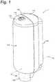
- FIG. 1shows a perspective view of a dispensing system 1 in which the present disclosure as claimed in the appended claims may be implemented.
- the dispensing system 1comprises a reusable dispenser 100 of the type used in washrooms and the like and available under the name TorkTM from SCA HYGIENE PRODUCTS AB.
- the dispenser 100is described in greater detail in WO2011/133085 . It will be understood that this embodiment is merely exemplary and that the present invention may also be implemented in other dispensing systems.
- the dispenser 100comprises a rear shell 110 and a front shell 112 that engage together to form a closed housing 116 that can be secured using a lock 118.
- the housing 116is affixed to a wall or other surface by a bracket portion 120.
- an actuator 124At a lower side of the housing 116 is an actuator 124, by which the dispensing system 1 may be manually operated to dispense a dose of cleaning fluid or the like.
- the operationas will be further described below, is described in the context of a manual actuator but the invention is equally applicable to automatic actuation e.g. using a motor and sensor.
- Figure 2shows in perspective view the dispenser 100 with the housing 116 in the open configuration and with a disposable container 200 and pump assembly 300 contained therein.
- the container 200is a 1000 ml collapsible container of the type described in WO2011/133085 and also in WO2009/104992 .
- the container 200is of generally cylindrical form and is made of polyethylene. The skilled person will understand that other volumes, shapes and materials are equally applicable and that the container 200 may be adapted according to the shape of the dispenser 100 and according to the fluid to be dispensed.
- the pump assembly 300has an outer configuration that corresponds substantially to that described in WO2011/133085 . This allows the pump assembly 300 to be used interchangeably with existing dispensers 100. Nevertheless, the interior configuration of the pump assembly 300 is distinct from both the pump of WO2011/133085 and that of WO2009/104992 , as will be further described below.
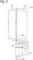
- FIG. 3shows the disposable container 200 and pump assembly 300 in side view.
- the container 200comprises two portions, namely a hard, rear portion 210 and a soft, front portion 212. Both portions 210, 212 are made of the same material but having different thicknesses.
- the front portion 210collapses into the rear portion as liquid is dispensed by the pump assembly 300. This construction avoids the problem with a build-up of vacuum within the container 200.
- other types of reservoirmay also be used in the context of the present disclosure, including but not limited to bags, pouches, cylinders and the like, both closed and opened to the atmosphere.
- the containermay be filled with soap, detergent, disinfectant, skin-care liquid, moisturizers or any other appropriate fluid and even medicaments.
- the fluidwill be aqueous although the skilled person will understand that other substances may be used where appropriate, including oils, solvents, alcohols and the like.
- the dispenser 1may also dispense fluids such as dispersions, suspensions or particulates.
- a rigid neck 214provided with a connecting flange 216.
- the connecting flange 216engages with a stationary sleeve 310 of the pump assembly 300.
- the pump assembly 300also includes a sliding sleeve 312, which terminates at an orifice 318.
- the sliding sleeve 312carries an actuating flange 314 and the stationary sleeve has a locating flange 316.
- Both the sleeves 310, 312are injection moulded of polycarbonate although the skilled person will be well aware that other relatively rigid, mouldable materials may be used. In use, as will be described in further detail below, the sliding sleeve 312 is displaceable by a distance D with respect to the stationary sleeve 310 in order to perform a single pumping action.
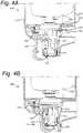
- Figures 4A and 4Bshow partial cross-sectional views through the dispenser 100 of Figure 1 , illustrating the pump assembly 300 in operation.
- the locating flange 316is engaged by a locating groove 130 on the rear shell 110.
- the actuator 124is pivoted at pivot 132 to the front shell 112 and includes an engagement portion 134 that engages beneath the actuating flange 314.
- Figure 4Bshows the position of the pump assembly 300 once a user has exerted a force P on actuator 124.
- the actuator 124has rotated anti-clockwise about the pivot 132, causing the engagement portion 134 to act against the actuating flange 314 with a force F, causing it to move upwards.
- the dispensing system 1 and its operationis essentially the same as that of the existing system known from WO2011/133085 .
- Figure 5shows the pump assembly 300 of Figure 3 in exploded perspective view illustrating the stationary sleeve 310, the sliding sleeve 312, spring 400 and pump body 500 axially aligned along axis A.
- the stationary sleeve 310is provided on its outer surface with three axially extending guides 340, each having a detent surface 342.
- the sliding sleeve 312is provided with three axially extending slots 344 through its outer surface, the functions of which will be described further below.
- FIG. 6shows an enlarged perspective view of the spring 400, which is injection moulded in a single piece from ethylene octene material from ExxonMobil Chemical Co.
- Spring 400comprises a first end portion 402 and a second end portion 404 aligned with each other along the axis A and joined together by a plurality of rhombus shaped spring sections 406.
- five spring sections 406are shown although the skilled person will understand that more or less such sections may be present according to the spring constant required.
- Each spring section 406comprises four flat leaves 408, joined together along hinge lines 410 that are parallel to each other and perpendicular to the axis A.
- the leaves 408have curved edges 428 and the spring sections 406 join at adjacent corners 412 .
- the first end portion 402includes a ring element 414 and a cross-shaped support element 416.
- An opening 418is formed through the ring element 414.
- the cross-shaped support element 416is interrupted intermediate its ends by an integrally formed first valve element 420 that surrounds the first end portion 402 at this point.
- the second end portion 404has a rib 430 and a frusto-conical shaped body 432 that narrows in a direction away from the first end portion 402.
- the frusto-conical shaped body 432On its exterior surface the frusto-conical shaped body 432 is formed with two diametrically opposed flow passages 434. At its extremity it is provided with an integrally formed second valve element 436 projecting conically outwardly and extending away from the first end portion.
- Figures 7-10are respective front, side and first and second end elevations of the spring 400.
- the ring element 414 and cross-shaped support element 416can be seen, together with the first valve element 420.
- the first valve element 420is part spherical in shape and extends to an outer edge 440 that is slightly wider than the cross-shaped support element 416.
- the rhombus shape of the spring sections 406can be clearly seen.
- the spring 400is depicted in its unstressed condition and the corners 412 define an internal angle ⁇ of around 115°. The skilled person will recognise that this angle may be adjusted to modify the spring properties and may vary from 60 to 160 degrees, preferably from 100 to 130 degrees and more preferably between 90 and 120 degrees. Also visible is the frusto-conical shaped body 432 of the second end portion 404 with rib 430, flow passages 434 and second valve element 436.
- Figure 8depicts the spring 400 in side view, viewed in the plane of the rhombus-shape of the spring sections 406.
- the hinge lines 410can be seen, as can be the curved edges 428. It will be noted that the hinge lines 410' at the corners 412, where adjacent spring sections 406 join, are significantly longer than the hinge lines 410 where adjacent flat leaves 408 join.
- Figure 9is a view onto the first end portion 402 showing the ring element 414 with the cross-shaped support element 416 viewed through opening 418.
- Figure 10shows the spring 400 viewed from the opposite end to Figure 9 , with the second valve element 436 at the centre and the frusto-conical shaped body 432 of the second end portion 404 behind it, interrupted by flow passages 434. Behind the second end portion 404, the curved edges 428 of the adjacent spring section 406 can be seen, which in this view define a substantially circular shape.
- the ring element 414is the widest portion of the spring 400.
- FIG 11is a cross-sectional view along line XI-XI in Figure 8 showing the variation in thickness through the flat leaves 408 at the hinge line 410'.
- each leaf 408is thickest at its mid-line at location Y-Y and is feathered towards the curved edges 428, which are thinner.
- This tapering shapeconcentrates the material strength of the spring towards the mid-line and the force about the mid-line and concentrates the force about the axis A.
- FIG 12shows the pump body 500 of Figure 5 in front elevation in greater detail.
- pump body 500is also manufactured of the same plastomer material as the spring 400. This is advantageous both in the context of manufacturing and disposal, although the skilled person will understand that different materials may be used for the respective parts.
- Pump body 500comprises a pump chamber 510, which extends from a pump inlet 502 to a pump outlet 504.
- the pump outlet 504is of a smaller diameter than the pump chamber 510 and terminates in a nozzle 512, which is initially closed by a twist-off closure 514.
- Set back from the nozzle 512is an annular protrusion 516.
- the pump inlet 502comprises a boot portion 518 that is rolled over on itself and terminates in a thickened rim 520.
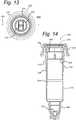
- Figure 13shows an end view of the pump body 500 directed onto the pump outlet 504.
- the pump body 500is rotationally symmetrical, with the exception of the twist-off closure 514, which is rectangular.
- the variation in diameter between the pump outlet 504, the pump chamber 510 and the thickened rim 520can be seen.
- FIG 14is a longitudinal cross-sectional view of the pump body 500 taken in direction XIV-XIV in Figure 13 .
- the pump chamber 510comprises a flexible wall 530, having a thick-walled section 532 adjacent to the pump inlet 502 and a thin-walled section 534 adjacent to the pump outlet 504.
- the thin-walled section 534 and the thick-walled section 532join at a transition 536.
- the thin-walled section 534tapers in thickness from the transition 536 with a decreasing wall thickness towards the pump outlet 504.
- the thick-walled section 532tapers in thickness from the transition 536 with an increasing wall thickness towards the pump inlet 502.
- the thick-walled section 532also includes an inlet valve seat 538 at which the internal diameter of the pump chamber 510 reduces as it transitions to the pump inlet 502.
- an annular groove 540within the pump body 500 at the pump inlet 502 and sealing ridges 542 on an exterior surface of the boot portion 518.
- FIG 15is a cross-sectional view through the pump assembly 300 of Figure 3 , showing the spring 400, the pump body 500 and the sleeves 310, 312, connected together in a position prior to use.
- Stationary sleeve 310includes a socket 330 opening towards its upper side.
- the socket 330has an upwardly extending male portion 332 sized to engage within the boot portion 518 of the pump body 500.
- the socket 330also includes inwardly directed cams 334 on its inner surface of a size to engage with the connecting flange 216 on the rigid neck 214 of container 200 in a snap connection.
- Figure 15also depicts the engagement between the spring 400 and the pump body 500.
- the inlet portion 402 of the spring 400is sized to fit within the pump inlet 502 with the ring element 414 engaged in the groove 540 and the cross-shaped support element 416 engaging against the interior surface of the pump inlet 502 and the adjacent pump chamber 510.
- the first valve element 420rests against the inlet valve seat 538 with a slight pre-load, sufficient to maintain a fluid-tight seal in the absence of any external pressure.
- the outlet portion 404engages within the pump outlet 504.
- the rib 430has a greater diameter than the pump outlet 504 and serves to position the frusto-conical shaped body 432 and the second valve element 436 within the pump outlet 504.
- the outside of the pump outlet 504also engages within the orifice 318 of the sliding sleeve 312 with the nozzle 512 slightly protruding.
- the annular protrusion 516is sized to be slightly larger than the orifice 318 and maintains the pump outlet 504 at the correct position within the orifice 318.
- the second valve element 436has an outer diameter that is slightly larger than the inner diameter of the pump outlet 504, whereby a slight pre-load is also applied, sufficient to maintain a fluid-tight seal in the absence of any external pressure.
- Figure 15also shows how the sleeves 310, 312 engage together in operation.
- the sliding sleeve 312is slightly larger in diameter than the stationary sleeve 310 and encircles it.
- the three axial guides 340 on the outer surface of the stationary sleeve 310engage within respective slots 344 in the sliding sleeve.
- the spring 400is in its initial condition being subject to a slight pre-compression and the detent surfaces 342 engage against the actuating flange 314.
- the container 200 and pump assembly 300are permanently connected together and are supplied and disposed of as a single disposable unit.
- the snap connection between socket 330 and the connecting flange 216 on the container 200prevents the stationary sleeve 310 from being separated from the container 200.
- the detent surfaces 342prevent the sliding sleeve 312 from being removed from its position around the stationary sleeve 310 and the pump body 500 and spring 400 are retained within the sleeves 310, 312.
- FIG 16shows a similar view to Figure 15 with the twist-off closure 514 removed.
- the pump assembly 300is now ready for use and may be installed into a dispenser 100 as shown in Figure 2 .
- the pump chamber 510is full of fluid to be dispensed although it will be understood that on first opening of the twist-off closure 514, the pump chamber 510 may be full of air.
- the second valve element 436seals against the inner diameter of the pump outlet 504, preventing any fluid from exiting through the nozzle 512.
- Figure 17shows the pump assembly 300 of Figure 16 as actuation of a dispensing stroke is commenced, corresponding to the action described in relation to Figures 4A and 4B .
- engagement of actuator 124 by a usercauses the engagement portion 134 to act against the actuating flange 314 exerting a force F.
- the container 200has been omitted for the sake of clarity.
- the force Fcauses the actuating flange 314 to move out of engagement with the detent surfaces 342 and the sliding sleeve 312 to move upwards with respect to the stationary sleeve 310.
- This forceis also transmitted by the orifice 318 and the annular protrusion 516 to the pump outlet 504, causing this to move upwards together with the sliding sleeve 312.
- the other end of the pump body 400is prevented from moving upwards by engagement of the pump inlet 502 with the socket 330 of the stationary sleeve 310.
- the movement of the sliding sleeve 312 with respect to the stationary sleeve 310causes an axial force to be applied to the pump body 400.
- This forceis transmitted through the flexible wall 530 of the pump chamber 510, which initially starts to collapse at its weakest point, namely the thin walled section 534 adjacent to the pump outlet 504.
- the pump chamber 510collapses, its volume is reduced and fluid is ejected through the nozzle 512.
- Reverse flow of fluid through the pump inlet 502is prevented by the first valve element 420, which is pressed against the inlet valve seat 538 by the additional fluid pressure within the pump chamber 510.
- the forceis transmitted through the spring 400 by virtue of the engagement between the rib 430 and the pump outlet 504 and the ring element 414 being engaged in the groove 540 at the pump inlet 502. This causes the spring 400 to compress, whereby the internal angle ⁇ at the corners 412 increases.
- FIG 17Ais a detail in perspective of the pump outlet 504 of Figure 17 , showing in greater detail how second valve element 436 operates.
- spring 400is shown unsectioned.
- thin walled section 534has collapsed by partially inverting on itself adjacent to the annular protrusion 516.
- the pump outlet 504has a relatively thicker wall and is supported within the orifice 318, maintaining its form and preventing distortion or collapse.
- rib 430is interrupted at flow passage 434, which extends along the outer surface of the frusto-conical shaped body 432 to the second valve element 436.
- This flow passage 434allows fluid to pass from the pump chamber 510 to engage with the second valve element 436 and exert a pressure onto it.
- the pressurecauses the material of the second valve element 436 to flex away from engagement with the inner wall of the pump outlet 504, whereby fluid can pass the second valve element 436 and reach the nozzle 512.
- the precise manner in which the second valve element 436 collapseswill depend upon the degree and speed of application of the force F and other factors such as the nature of the fluid, the pre-load on the second valve element 436 and its material and dimensions. These may be optimised as required.
- Figure 18shows the pump assembly 300 of Figure 17 in fully compressed state on completion of an actuation stroke.
- the sliding sleeve 312has moved upwards a distance D with respect to the initial position of Figure 16 and the actuating flange 314 has entered into abutment with the locating flange 316.
- pump chamber 310has collapsed to its maximum extent whereby the thin walled section 534 has fully inverted.
- the spring 400has also collapsed to its maximum extent with all of the rhombus-shaped spring section 406 fully collapsed to a substantially flat configuration in which the leaves 408 lie close against each other and, in fact all of the leaves 408 are almost parallel to each other. It will be noted that although reference is given to fully compressed and collapsed conditions, this need not be the case and operation of the pump assembly 300 may take place over just a portion of the full range of movement of the respective components.
- the spring 400which was initially slightly spaced from the flexible wall 530, engages into contact with the pump chamber. At least in the region of the thin walled section 534, the spring sections 406 exert a force on the flexible wall 530, causing it to stretch.
- the stroke, defined by distance Dis around 14 mm and the volume of fluid dispensed is about 1.1 ml. It will be understood that these distances and volumes can be adjusted according to requirements.
- the compressed spring 400will exert a net restoring force on the pump body 500.
- the spring depicted in the present embodimentexerts an axial force of 20N in its fully compressed condition. This force, acts between the ring element 414 and the rib 430 and exerts a restoring force between the pump inlet 502 and the pump outlet 504 to cause the pump chamber 510 to revert to its original condition.
- the pump body 500by its engagement with the sleeves 310, 312 also causes these elements to return towards their initial position as shown in Figure 16 .
- the pump chamber 510also increases in volume leading to an under pressure within the fluid contained within the pump chamber 510.
- the second valve element 436is closed and any under pressure causes the second valve element 436 to engage more securely against the inner surface of the pump outlet 504.
- Figure 18Ashows a perspective detail of part of the pump inlet 502 of Figure 18 .
- the first valve element 420can flex away from the inlet valve seat 538 due to the lower pressure in the pump chamber 510 compared to that in the container 200. This causes fluid to flow into the pump chamber 510 through the rigid neck 214 of the container 200 and the opening 418 formed through the ring element 414 and over the cross-shaped support element 416.
- the springmay provide a major restoring force during the return stroke.
- its forcemay also be partially augmented by radial pressure acting on it from the flexible wall 530 of the pump chamber 510.
- the pump chamber 510may also exert its own restoring force on the sliding sleeve 312 due to the inversion of the thin walled section 534, which attempts to revert to its original shape.
- Neither the restoring force of the spring 400 nor that of the pump chamber 510is linear but the two may be adapted together to provide a desirable spring characteristic.
- the pump chamber 510may exert a relatively strong restoring force at the position depicted in Figure 17 , at which the flexible wall 530 just starts to invert.
- the spring 400may exert its maximum restoring force when it is fully compressed in the position according to Figure 18 .
- the spring 400 of Figures 6 to 11 and pump body 500 of Figures 12 to 14are dimensioned for pumping a volume of around 1-2 ml, e.g. around 1.1 ml.
- the flat leaves 408In a pump dimensioned for 1.1 ml, the flat leaves 408 have a length of around 7 mm, measured as the distance between hinge lines 410 about which they flex. They have a thickness at their mid-lines of around 1 mm.
- the overall length of the springis around 58 mm.
- the pump body 400has an overall length of around 70 mm, with the pump chamber 510 comprising around 40 mm and having an internal diameter of around 15 mm and a minimal wall thickness of around 0.5 mm. The skilled person will understand that these dimensions are exemplary.
- the pump/springmay develop a maximum resistance of between 1 N and 50 N, more specifically between 20 N and 25 N on compression.
- the pump/spring bias on the reverse stroke for an empty pumpmay be between 1 N and 50 N, preferably between 1 N and 30 N more preferably between 5 N and 20 N, most preferably between 10 N and 15 N.
- the compression and bias forcesmay depend on and be proportional to the intended volume of the pump. The values given above may be appropriate for a 1 ml pump stroke.
Landscapes
- Health & Medical Sciences (AREA)
- Public Health (AREA)
- Physics & Mathematics (AREA)
- Fluid Mechanics (AREA)
- General Physics & Mathematics (AREA)
- Containers And Packaging Bodies Having A Special Means To Remove Contents (AREA)
- Reciprocating Pumps (AREA)
- Springs (AREA)
Description
- The present invention relates to pumps of the type used for dispensing fluids and more particularly to a spring for use in a pump for dispensing cleaning, sterilising or skin care product, e.g. products such as soaps, gels, disinfectants, moisturizer and the like. The invention is specifically directed to pumps and springs that are axially compressible and that cause dispensing by an axial reduction in volume of a pump chamber.
- Fluid dispensers of various types are known. In particular, for dispensing of cleaning products such as soaps, there are a wide variety of manually or automatically actuated pumps that dispense a given quantity of the product into a user's hand.
- Consumer products may comprise a dispensing outlet as part of the package, actuated by a user pressing down the top of the package. Such packages use a dip tube extending below the level of the liquid and a piston pump that aspirates the liquid and dispenses it downwards through an outlet spout.
- Commercial dispensers frequently use inverted disposable containers that can be placed in dispensing devices, affixed to walls of washrooms or the like. The pump may be integrated as part of the disposable container or may be part of the permanent dispensing device or both. Such devices are generally more robust and, as they are affixed to the wall, greater freedom is available in the direction and amount of force that is required for actuation. Such devices may also use sensors that identify the location of a user's hand and cause a unit dose of the product to be dispensed. This avoids user contact with the device and the associated cross-contamination. It also prevents incorrect operation that can lead to damage and premature ageing of the dispensing mechanism.
- A characteristic of inverted dispensers is the need to prevent leakage. Since the pump outlet is located below the container, gravity will act to cause the product to escape if there is any leakage through the pump. This is particularly the case for relatively volatile products such as alcohol based solutions. Achieving leak free operation is often associated with relatively complex and expensive pumps. For the convenience of replacing empty disposable containers however, at least part of the pump is generally also disposable and must be economical to produce. There is therefore a need for a pump that is reliable and drip free, yet simple and economical to produce.
- One disposable dispensing system that uses a pump to dispense a unit dose of liquid from an inverted collapsible container has been described in
WO2009/104992 . The pump is formed of just two elements, namely a resilient pumping chamber and a regulator, having an inner valve and an outer valve. Operation of the pump occurs by application of a lateral force to the pumping chamber, causing it to partially collapse and expel its contents through the outer valve. Refilling of the pumping chamber occurs through the inner valve once the lateral force is removed. The filling force is provided by the inherent resilience of the wall of the pumping chamber, which must be sufficient to overcome any back-pressure due to a resistance to collapse of the container. Although the pump is extremely effective, the lateral force required to operate the pump can sometimes limit its integration into a dispenser body. Other dispensing systems use an axial force i.e. directed in alignment with the direction in which the fluid is dispensed. It would be desirable to provide a pump that could operate in this manner that could also be integrated into existing axially operating dispensers. Other pumps are shown inJP HI 0 72052 A WO 2013/035316 ,ITAMI20130336 A1 JP HI 0 47400 A - In view of the fluid pumps of the above-mentioned types, one object of the present invention is to provide an alternative pump. The pump may be disposable and is desirably reliable and drip free when used, yet simple, hygienic and economical to produce.
- The invention relates in particular to a pump comprising a plastomer spring according to appended claim land further to a pump assembly according to appended claim 13, a method of dispensing a fluid according to appended claim 14 and a dispenser according to appended claim 15. Embodiments are set forth in the appended dependent claims, in the following description and in the drawings.
- Thus, there is disclosed a plastomer spring for use in a fluid pump, the spring comprising a first end portion and a second end portion and a plurality of spring sections, joined together in series and aligned with each other in an axial direction to connect the first end portion to the second end portion, which spring sections can be compressed in the axial direction from an initial condition to a compressed condition and can subsequently expand to their initial condition. By providing a plastomer element, operable in an axial direction in this manner, a stable spring may be obtained that does not twist or otherwise distort during compression and may be easily manufactured by injection moulding in a single piece. Unlike metal springs, by the use of polymer materials, the spring may be made compatible with multiple different cleaning, sterilising or skin care fluids, without the risk of corrosion or contamination. The fluid may be soap, detergent, disinfectant, moisturizer or any other form of cleaning, sterilising or skin care product. Furthermore, recycling of the pump may be facilitated, given that other elements of the pump are also of polymer material.
- The spring sections may be rhombus shaped, joined together at adjacent corners. In the present context, reference to "rhombus shaped" is not intended to limit the invention to spring sections of the precise geometrical shape having flat sides and sharp corners. The skilled person will understand that the shape is intended to denote an injection mouldable form that will allow resilient collapse, while using the material properties of the plastomer to generate a restoring force. Furthermore, since the resiliency of the structure is at least partially provided by the material at the corner regions, these may be at least partially reinforced, curved, radiused or the like in order to optimise the required spring characteristic. In one preferred embodiment, each spring section comprises four flat leaves joined together along hinge lines that are parallel to each other and perpendicular to the axial direction. In this context, flat is intended to denote planar. The resulting configuration may also be described as concertina like.
- The flat leaves may be of constant thickness over their area. The thickness may be between 0.5 mm and 1.5 mm, depending on the material used and the geometrical design of the pump and the spring. For example, a thickness between 0.7 and 1.2 mm has been found to offer excellent collapse characteristics in the case of leaves having a length between hinge lines of around 7 mm. In other words, the ratio of the thickness of the leaf to its length may be around 1:10, but may range from a ratio of 1:5 to a ratio of 1:15. The skilled person will recognise that for a given material, this ratio will be of significance in determining the spring constant of the resulting spring. In one preferred alternative, the leaves may be thicker at their midline and may be thinned or feathered towards their edges. This feathering may be advantageous from a moulding perspective, allowing easier extraction from the mould. It also serves to concentrate the majority of the spring force to the midline. Where the spring is to be located in a cylindrical housing, this is the portion of the spring that provides the majority of the restoring force.
- Additionally, as a measure to allow the spring to be installed in a cylindrical housing or pump chamber, the spring sections may have curved edges. The spring may then have a generally circular configuration, as viewed in the axial direction i.e. it may define a cylindrical outline. It will be understood that the curved edges may be sized such that the spring is cylindrical in its unstressed initial condition or in its compressed condition or at an intermediate position between these two extremes, preferably in its compressed condition.
- The precise configuration of the spring will depend on the characteristics required in terms of extension and spring constant. An important factor in determining the degree of extension of the spring is the initial geometry of the rhombus shapes of the spring sections. In one preferred embodiment the spring sections, in their initial condition, join at adjacent corners having an internal angle α of between 90 and 120 degrees. In a fully relaxed spring, angle α may be between 60 to 160 or 100 to 130 degrees, depending on the geometries and materials used for the spring as well as the pump body. The angle α is normally slightly higher when the spring is inserted into the pump chamber and in its initial stage before pump compression occurs, e.g. 5-10 degrees higher than for a fully relaxed spring, For a spring in its compressed condition, the angle α increases towards 180 degrees and for example may be 160 to 180 degrees in a compressed condition. For example, the angle α may be 120 degrees for a spring in an initial condition and 160 degrees for a spring in a compressed condition.
- A particularly desirable characteristic of the disclosed spring is its ability to undergo a significant reduction in length. Preferably, the spring sections are arranged to compress from an open configuration to a substantially flat configuration in which the spring sections or the leaves lie close against each other i.e. adjacent sides of the rhombus shaped spring sections become co-planar.
- In a particular embodiment, each spring section may be able to compress axially to less than 60%, preferably less than 50 % of its uncompressed length. The overall reduction in length will depend on the number of spring sections and in actual operation, there may be neither need nor desire to compress each spring section to the maximum. In a particular embodiment, the spring may comprise at least three spring sections which may preferably be identical in geometry. A most preferred embodiment has five spring section, which offers a good compromise between stability and range of compression.
- The skilled person will be aware of various polymer materials that could provide the desired elastic properties required to achieve compression and recovery without excessive hysteresis losses. Thermoplastic polymers that can function like elastomers are generally referred to as plastomers. In the present context, reference to plastomer material is intended to include all thermoplastic elastomers that are elastic at ambient temperature and become plastically deformable at elevated temperatures, such that they can be processed as a melt and be extruded or injection moulded.
- The disclosure is primarily directed to the configuration of the spring. Nevertheless, because a plastomer spring can be formed by injection moulding and according to a particularly significant aspect, the spring may be integrally formed with additional elements, e.g. those required for its function as part of a fluid pump. In particular, the first and second end portions may be formed to interact with other components of the pump to maintain the spring in position. In one embodiment, they may form cylindrical or part-cylindrical plugs. The first and second end portions may also be formed with passages or channels to allow fluid to flow along the spring past or through these respective portions.
In one embodiment, the spring may further comprise an integrally formed first valve element. The first valve element may be a circumferential element formed around the first end portion, projecting outwardly and may preferably be formed as one of a circumferential skirt or truncated cone extending towards the second end portion, and a planar disk. The circumferential element may have a diameter that extends beyond the width of the spring sections and may be part spherical. - The spring may further comprise an integrally formed second valve element comprising a circumferential element formed on the second end portion, projecting outwardly and may preferably be formed as one of a planar disk, and a circumferential skirt or truncated cone extending from the second end portion. The second valve element may surround the second end portion or extend axially beyond the second end portion. In one embodiment, the second valve element may be conical or frusto-conical, widening in a direction away from the first end portion. The integration of one or more valve elements with the spring, reduces the number of components that must be manufactured and also simplifies the assembly operations. Given that these components are of the same type of material, their disposal may also be a single operation.
- The fluid pump comprises a pump body having an elongate pump chamber surrounding the spring and extending from a pump inlet adjacent to the first end portion to a pump outlet adjacent to the second end portion. As indicated above, the pump chamber may be cylindrical and the spring may also have an exterior profile that is cylindrical in order to match and fit the pump chamber. The spring may have an external cross-sectional shape that corresponds to an internal cross-section of the pump chamber. One preferred form of the pump chamber is cylindrical and the spring may also define a generally cylindrical envelope in this region.
- As indicated above, the material for the pump body and/or the spring may be a plastomer. A plastomer may be defined by its properties, such as the Shore hardness, the brittleness temperature and Vicat softening temperature, the flexural modulus, the ultimate tensile strength and the melt index. Depending on, for example, the type of fluid to be dispensed, and the size and geometry of the pump body or spring, the plastomer material used in the pump may be vary from a soft to a hard material. The plastomer material forming at least the spring may thus have a shore hardness of from 50 Shore A (ISO 868, measured at 23 degrees C) to 70 Shore D (ISO 868, measured at 23 degrees C). Optimal results may be obtained using a plastomer material having a shore A hardness of 70-95 or a shore D hardness of 20-50, e.g. a shore A hardness of 75-90. Furthermore, the plastomer material may have brittleness temperature (ASTM D476) being lower than -50 degrees Celsius, e.g. from -90 to -60 degrees C, and a Vicat softening temperature (ISO 306/SA) of 30-90 degrees Celsius, e.g. 40 - 80 degrees C. The plastomers may additionally have a flexural modulus in the range of 15 - 80 MPa, preferably 20 - 40 MPa or 30 - 50 MPa, most preferably 25 - 30 MPa (ASTM D-790), e.g. 26-28 MPa. Likewise, the plastomers preferably have an ultimate tensile strength in the range of 3 - 11 MPa, preferably 5 - 8 MPa (ASTM D-638). Additionally, the melt flow index may be at least 10 dg/min, and more preferably in the range of 20 - 50 dg/min (ISO standard 1133-1, measured at 190 degrees C).
- Suitable plastomers include natural and/or synthetic polymers. Particularly suitable plastomers include styrenic block copolymers, polyolefins, elastomeric alloys, thermoplastic polyurethanes, thermoplastic copolyesters and thermoplastic polyamides. In the case of polyolefins, the polyolefin is preferably used as a blend of at least two distinct polyolefins and/or as a co-polymer of at least two distinct monomers. In one embodiment, plastomers from the group of thermoplastic polyolefin blends are used, preferably from the group of polyolefin co-polymers. A preferred group of plastomers is the group of ethylene alpha olefin copolymers. Amongst these, ethylene 1-octene copolymers have been shown to be particularly suitable, especially those having the properties as defined above. Suitable plastomers are available from ExxonMobil Chemical Co. as well as Dow Chemical Co.
- It will be understood that the spring may be incorporated into the pump in a number of different ways to assist in the pumping action. According to the invention, the pump chamber is compressible together with the spring in the axial direction. This is achieved by providing the pump chamber with a flexible wall that distorts during compression of the pump chamber. According to the invention, the flexible wall inverts or roll-up as the spring compresses. The overall spring constant of the pump will then be the combined effect of the spring and the pump chamber. The spring may provide support to the pump chamber during its distortion. In this context, support is intended to denote that it prevents the pump chamber from distorting uncontrollably to a position in which it might not be able to restore itself. It may also assist in controlling the distortion to ensure a more constant recovery during the return stroke. It is noted that the pump body or the pump chamber may also provide support to the spring in order to allow it to compress axially in the desired manner.
- In order for the spring and pump body to operate effectively together, the first and second end portions may engage with the pump inlet and pump outlet respectively, to retain such engagement during compression of the pump chamber. To this effect, the end portions may be in the form of plugs as described above that closely fit into cylindrical recesses in the inlet and outlet respectively, while allowing passages for fluid to pass by.
- According to one embodiment, the spring and the pump body may be injection moulded of the same material. This is especially advantageous from the perspective of recycling and reduces the material streams during manufacture.
- Still more advantageously, because of the efficient design discussed above, the whole construction of the fluid pump may be achieved using just two components, namely the pump body and the spring, whereby the pump body and the spring interact to define a one-way inlet valve and a one-way outlet valve. As will be further discussed below, the first valve element may engage against a wall of the pump inlet while the second valve element may engage against a wall of the pump outlet.
- Various manufacturing procedures may be used to form the pump including blow moulding, thermoforming, 3D-printing and other methods. Some or all of the elements forming the pump may be manufactured by injection moulding. In a particular embodiment, the pump body and the spring may each be formed by injection moulding. They may both be of the same material or each may be optimised independently using different materials. As discussed above, the material may be optimised for its plastomer qualities and also for its suitability for injection moulding. Additionally, although in one embodiment, the spring is manufactured of a single material, it is not excluded that it may be manufactured of multiple materials.
- In the case that the spring is integrally formed to include inlet and outlet valves, the designer is faced with two conflicting requirements, to a large degree depending on the fluid that will be pumped:
- 1. The valves shall be flexible enough to allow for a good seal;
- 2. The spring shall be stiff enough to provide the required spring constant to pump the fluid.
- The disclosure further relates to a pump assembly comprising the pump assembly comprising a pump as described above, and a pair of sleeves, arranged to slidably interact to guide the pump during a pumping stroke, including a stationary sleeve engaged with the pump inlet and a sliding sleeve engaged with the pump outlet. The stationary sleeve and sliding sleeve may have mutually interacting detent surfaces that prevent their separation and define the pumping stroke. Furthermore, the stationary sleeve may comprise a socket having an axially extending male portion and the pump inlet has an outer diameter, dimensioned to engage within the socket and comprises a boot portion, rolled over on itself to receive the male portion.
- Moreover, the disclosure relates to a disposable fluid dispensing package, comprising a pump as described above or a pump assembly as earlier described, sealingly connected to a collapsible product container.
- The disclosure also relates to a method of dispensing a fluid from a fluid pump as described above or hereinafter by exerting an axial force on the pump body between the pump inlet and the pump outlet to cause axial compression of the spring and a reduction in volume of the pump chamber.
- The features and advantages of the present disclosure will be appreciated upon reference to the following drawings of a number of exemplary embodiments, in which:
Figure 1 shows a perspective view of a dispensing system in which the present disclosure as claimed in the appended claims may be implemented;Figure 2 shows the dispensing system ofFigure 1 in an open configuration;Figure 3 shows a disposable container and pump assembly according to the disclosure in side view;Figures 4A and 4B show partial cross-sectional views of the pump ofFigure 1 in operation;Figure 5 shows the pump assembly ofFigure 3 in exploded perspective view;Figure 6 shows the spring ofFigure 5 in perspective view;Figure 7 shows the spring ofFigure 6 in front view;Figure 8 shows the spring ofFigure 6 in side view;Figure 9 shows the spring ofFigure 6 in top view;Figure 10 shows the spring ofFigure 6 in bottom view;Figure 11 shows a cross-sectional view through the spring ofFigure 8 along line XI-XI;Figure 12 shows the pump chamber ofFigure 5 in front view;Figure 13 shows a bottom view of the pump body directed onto the pump outlet;Figure 14 is a longitudinal cross-sectional view of the pump body taken in direction XIV-XIV inFigure 13 ;Figures 15-18 are cross-sectional views through the pump assembly ofFigure 3 in various stages of operation;Figure 17A is a detail in perspective of the pump outlet ofFigure 17 ; andFigure 18A is a detail in perspective of the pump inlet ofFigure 18 .Figure 1 shows a perspective view of a dispensing system 1 in which the present disclosure as claimed in the appended claims may be implemented. The dispensing system 1 comprises areusable dispenser 100 of the type used in washrooms and the like and available under the name Tork™ from SCA HYGIENE PRODUCTS AB. Thedispenser 100 is described in greater detail inWO2011/133085 . It will be understood that this embodiment is merely exemplary and that the present invention may also be implemented in other dispensing systems.- The
dispenser 100 comprises arear shell 110 and afront shell 112 that engage together to form aclosed housing 116 that can be secured using alock 118. Thehousing 116 is affixed to a wall or other surface by abracket portion 120. At a lower side of thehousing 116 is anactuator 124, by which the dispensing system 1 may be manually operated to dispense a dose of cleaning fluid or the like. The operation, as will be further described below, is described in the context of a manual actuator but the invention is equally applicable to automatic actuation e.g. using a motor and sensor. Figure 2 shows in perspective view thedispenser 100 with thehousing 116 in the open configuration and with adisposable container 200 and pumpassembly 300 contained therein. Thecontainer 200 is a 1000 ml collapsible container of the type described inWO2011/133085 and also inWO2009/104992 . Thecontainer 200 is of generally cylindrical form and is made of polyethylene. The skilled person will understand that other volumes, shapes and materials are equally applicable and that thecontainer 200 may be adapted according to the shape of thedispenser 100 and according to the fluid to be dispensed.- The
pump assembly 300 has an outer configuration that corresponds substantially to that described inWO2011/133085 . This allows thepump assembly 300 to be used interchangeably with existingdispensers 100. Nevertheless, the interior configuration of thepump assembly 300 is distinct from both the pump ofWO2011/133085 and that ofWO2009/104992 , as will be further described below. Figure 3 , shows thedisposable container 200 and pumpassembly 300 in side view. As can be seen, thecontainer 200 comprises two portions, namely a hard,rear portion 210 and a soft,front portion 212. Bothportions container 200 empties, thefront portion 210 collapses into the rear portion as liquid is dispensed by thepump assembly 300. This construction avoids the problem with a build-up of vacuum within thecontainer 200. The skilled person will understand that although this is a preferred form of container, other types of reservoir may also be used in the context of the present disclosure, including but not limited to bags, pouches, cylinders and the like, both closed and opened to the atmosphere. The container may be filled with soap, detergent, disinfectant, skin-care liquid, moisturizers or any other appropriate fluid and even medicaments. In most cases, the fluid will be aqueous although the skilled person will understand that other substances may be used where appropriate, including oils, solvents, alcohols and the like. Furthermore, although reference will be made in the following to liquids, the dispenser 1 may also dispense fluids such as dispersions, suspensions or particulates.- At the lower side of the
container 200, there is provided arigid neck 214 provided with a connectingflange 216. The connectingflange 216 engages with astationary sleeve 310 of thepump assembly 300. Thepump assembly 300 also includes a slidingsleeve 312, which terminates at anorifice 318. The slidingsleeve 312 carries anactuating flange 314 and the stationary sleeve has a locatingflange 316. Both thesleeves sleeve 312 is displaceable by a distance D with respect to thestationary sleeve 310 in order to perform a single pumping action. Figures 4A and 4B show partial cross-sectional views through thedispenser 100 ofFigure 1 , illustrating thepump assembly 300 in operation. According toFigure 4A , the locatingflange 316 is engaged by a locatinggroove 130 on therear shell 110. Theactuator 124 is pivoted atpivot 132 to thefront shell 112 and includes anengagement portion 134 that engages beneath theactuating flange 314.Figure 4B shows the position of thepump assembly 300 once a user has exerted a force P onactuator 124. In this view, theactuator 124 has rotated anti-clockwise about thepivot 132, causing theengagement portion 134 to act against the actuatingflange 314 with a force F, causing it to move upwards. Thus far, the dispensing system 1 and its operation is essentially the same as that of the existing system known fromWO2011/133085 .Figure 5 shows thepump assembly 300 ofFigure 3 in exploded perspective view illustrating thestationary sleeve 310, the slidingsleeve 312,spring 400 and pumpbody 500 axially aligned along axis A. Thestationary sleeve 310 is provided on its outer surface with three axially extendingguides 340, each having adetent surface 342. The slidingsleeve 312 is provided with three axially extendingslots 344 through its outer surface, the functions of which will be described further below.Figure 6 shows an enlarged perspective view of thespring 400, which is injection moulded in a single piece from ethylene octene material from ExxonMobil Chemical Co.Spring 400 comprises afirst end portion 402 and asecond end portion 404 aligned with each other along the axis A and joined together by a plurality of rhombus shapedspring sections 406. In this embodiment, fivespring sections 406 are shown although the skilled person will understand that more or less such sections may be present according to the spring constant required. Eachspring section 406 comprises fourflat leaves 408, joined together alonghinge lines 410 that are parallel to each other and perpendicular to the axis A. Theleaves 408 havecurved edges 428 and thespring sections 406 join atadjacent corners 412 .- The
first end portion 402 includes aring element 414 and across-shaped support element 416. Anopening 418 is formed through thering element 414. Thecross-shaped support element 416 is interrupted intermediate its ends by an integrally formedfirst valve element 420 that surrounds thefirst end portion 402 at this point. - The
second end portion 404 has arib 430 and a frusto-conicalshaped body 432 that narrows in a direction away from thefirst end portion 402. On its exterior surface the frusto-conicalshaped body 432 is formed with two diametricallyopposed flow passages 434. At its extremity it is provided with an integrally formedsecond valve element 436 projecting conically outwardly and extending away from the first end portion. Figures 7-10 are respective front, side and first and second end elevations of thespring 400.- Starting with
Figure 7 , thering element 414 andcross-shaped support element 416 can be seen, together with thefirst valve element 420. In this view it may be noted that thefirst valve element 420 is part spherical in shape and extends to anouter edge 440 that is slightly wider than thecross-shaped support element 416. Also in this view, the rhombus shape of thespring sections 406 can be clearly seen. Thespring 400 is depicted in its unstressed condition and thecorners 412 define an internal angle α of around 115°. The skilled person will recognise that this angle may be adjusted to modify the spring properties and may vary from 60 to 160 degrees, preferably from 100 to 130 degrees and more preferably between 90 and 120 degrees. Also visible is the frusto-conicalshaped body 432 of thesecond end portion 404 withrib 430, flowpassages 434 andsecond valve element 436. Figure 8 depicts thespring 400 in side view, viewed in the plane of the rhombus-shape of thespring sections 406. In this view, thehinge lines 410 can be seen, as can be the curved edges 428. It will be noted that the hinge lines 410' at thecorners 412, whereadjacent spring sections 406 join, are significantly longer than thehinge lines 410 where adjacentflat leaves 408 join.Figure 9 is a view onto thefirst end portion 402 showing thering element 414 with thecross-shaped support element 416 viewed throughopening 418.Figure 10 shows thespring 400 viewed from the opposite end toFigure 9 , with thesecond valve element 436 at the centre and the frusto-conicalshaped body 432 of thesecond end portion 404 behind it, interrupted byflow passages 434. Behind thesecond end portion 404, thecurved edges 428 of theadjacent spring section 406 can be seen, which in this view define a substantially circular shape. In the shown embodiment, thering element 414 is the widest portion of thespring 400.Figure 11 , is a cross-sectional view along line XI-XI inFigure 8 showing the variation in thickness through theflat leaves 408 at the hinge line 410'. As can be seen, eachleaf 408 is thickest at its mid-line at location Y-Y and is feathered towards thecurved edges 428, which are thinner. This tapering shape concentrates the material strength of the spring towards the mid-line and the force about the mid-line and concentrates the force about the axis A.Figure 12 shows thepump body 500 ofFigure 5 in front elevation in greater detail. In this embodiment,pump body 500 is also manufactured of the same plastomer material as thespring 400. This is advantageous both in the context of manufacturing and disposal, although the skilled person will understand that different materials may be used for the respective parts.Pump body 500 comprises apump chamber 510, which extends from apump inlet 502 to apump outlet 504. Thepump outlet 504 is of a smaller diameter than thepump chamber 510 and terminates in anozzle 512, which is initially closed by a twist-off closure 514. Set back from thenozzle 512 is anannular protrusion 516. Thepump inlet 502 comprises aboot portion 518 that is rolled over on itself and terminates in a thickenedrim 520.Figure 13 shows an end view of thepump body 500 directed onto thepump outlet 504. Thepump body 500 is rotationally symmetrical, with the exception of the twist-off closure 514, which is rectangular. The variation in diameter between thepump outlet 504, thepump chamber 510 and the thickenedrim 520 can be seen.Figure 14 is a longitudinal cross-sectional view of thepump body 500 taken in direction XIV-XIV inFigure 13 . Thepump chamber 510 comprises aflexible wall 530, having a thick-walled section 532 adjacent to thepump inlet 502 and a thin-walled section 534 adjacent to thepump outlet 504. The thin-walled section 534 and the thick-walled section 532 join at atransition 536. The thin-walled section 534 tapers in thickness from thetransition 536 with a decreasing wall thickness towards thepump outlet 504. The thick-walled section 532 tapers in thickness from thetransition 536 with an increasing wall thickness towards thepump inlet 502. The thick-walled section 532 also includes aninlet valve seat 538 at which the internal diameter of thepump chamber 510 reduces as it transitions to thepump inlet 502. In addition to the variations in wall thickness of thepump chamber 510, there is also provided anannular groove 540 within thepump body 500 at thepump inlet 502 and sealingridges 542 on an exterior surface of theboot portion 518.Figure 15 is a cross-sectional view through thepump assembly 300 ofFigure 3 , showing thespring 400, thepump body 500 and thesleeves Stationary sleeve 310 includes asocket 330 opening towards its upper side. Thesocket 330 has an upwardly extendingmale portion 332 sized to engage within theboot portion 518 of thepump body 500. Thesocket 330 also includes inwardly directedcams 334 on its inner surface of a size to engage with the connectingflange 216 on therigid neck 214 ofcontainer 200 in a snap connection. The engagement of these three portions results in a fluid tight seal, due to the flexible nature of the material of thepump body 500 being gripped between the relatively more rigid material of the connectingflange 216 and thestationary sleeve 310. Additionally, the sealingridges 542 on the exterior surface of theboot portion 518 engage within therigid neck 214 in the manner of a stopper. In the depicted embodiment, this connection is a permanent connection but it will be understood that other e.g. releasable connections may be provided between thepump assembly 300 and thecontainer 200.Figure 15 also depicts the engagement between thespring 400 and thepump body 500. Theinlet portion 402 of thespring 400 is sized to fit within thepump inlet 502 with thering element 414 engaged in thegroove 540 and thecross-shaped support element 416 engaging against the interior surface of thepump inlet 502 and theadjacent pump chamber 510. Thefirst valve element 420 rests against theinlet valve seat 538 with a slight pre-load, sufficient to maintain a fluid-tight seal in the absence of any external pressure.- At the other end of the
pump body 500, theoutlet portion 404 engages within thepump outlet 504. Therib 430 has a greater diameter than thepump outlet 504 and serves to position the frusto-conicalshaped body 432 and thesecond valve element 436 within thepump outlet 504. The outside of thepump outlet 504 also engages within theorifice 318 of the slidingsleeve 312 with thenozzle 512 slightly protruding. Theannular protrusion 516 is sized to be slightly larger than theorifice 318 and maintains thepump outlet 504 at the correct position within theorifice 318. Thesecond valve element 436 has an outer diameter that is slightly larger than the inner diameter of thepump outlet 504, whereby a slight pre-load is also applied, sufficient to maintain a fluid-tight seal in the absence of any external pressure. Figure 15 also shows how thesleeves sleeve 312 is slightly larger in diameter than thestationary sleeve 310 and encircles it. The threeaxial guides 340 on the outer surface of thestationary sleeve 310 engage withinrespective slots 344 in the sliding sleeve. In the position shown inFigure 15 , thespring 400 is in its initial condition being subject to a slight pre-compression and the detent surfaces 342 engage against the actuatingflange 314.- In the position shown in
Figure 15 , thecontainer 200 and pumpassembly 300 are permanently connected together and are supplied and disposed of as a single disposable unit. The snap connection betweensocket 330 and the connectingflange 216 on thecontainer 200 prevents thestationary sleeve 310 from being separated from thecontainer 200. The detent surfaces 342 prevent the slidingsleeve 312 from being removed from its position around thestationary sleeve 310 and thepump body 500 andspring 400 are retained within thesleeves Figure 16 shows a similar view toFigure 15 with the twist-off closure 514 removed. Thepump assembly 300 is now ready for use and may be installed into adispenser 100 as shown inFigure 2 . For the sake of the following description, thepump chamber 510 is full of fluid to be dispensed although it will be understood that on first opening of the twist-off closure 514, thepump chamber 510 may be full of air. In this condition, thesecond valve element 436 seals against the inner diameter of thepump outlet 504, preventing any fluid from exiting through thenozzle 512.Figure 17 shows thepump assembly 300 ofFigure 16 as actuation of a dispensing stroke is commenced, corresponding to the action described in relation toFigures 4A and 4B . As previously described in relation to those figures, engagement ofactuator 124 by a user causes theengagement portion 134 to act against the actuatingflange 314 exerting a force F. In this view, thecontainer 200 has been omitted for the sake of clarity.- The force F causes the
actuating flange 314 to move out of engagement with the detent surfaces 342 and the slidingsleeve 312 to move upwards with respect to thestationary sleeve 310. This force is also transmitted by theorifice 318 and theannular protrusion 516 to thepump outlet 504, causing this to move upwards together with the slidingsleeve 312. The other end of thepump body 400 is prevented from moving upwards by engagement of thepump inlet 502 with thesocket 330 of thestationary sleeve 310. - The movement of the sliding
sleeve 312 with respect to thestationary sleeve 310 causes an axial force to be applied to thepump body 400. This force is transmitted through theflexible wall 530 of thepump chamber 510, which initially starts to collapse at its weakest point, namely the thinwalled section 534 adjacent to thepump outlet 504. As thepump chamber 510 collapses, its volume is reduced and fluid is ejected through thenozzle 512. Reverse flow of fluid through thepump inlet 502 is prevented by thefirst valve element 420, which is pressed against theinlet valve seat 538 by the additional fluid pressure within thepump chamber 510. - Additionally, the force is transmitted through the
spring 400 by virtue of the engagement between therib 430 and thepump outlet 504 and thering element 414 being engaged in thegroove 540 at thepump inlet 502. This causes thespring 400 to compress, whereby the internal angle α at thecorners 412 increases. Figure 17A is a detail in perspective of thepump outlet 504 ofFigure 17 , showing in greater detail howsecond valve element 436 operates. In this view,spring 400 is shown unsectioned. As can be seen, thinwalled section 534 has collapsed by partially inverting on itself adjacent to theannular protrusion 516. Below theannular protrusion 516, thepump outlet 504 has a relatively thicker wall and is supported within theorifice 318, maintaining its form and preventing distortion or collapse. As can also be seen in this view,rib 430 is interrupted atflow passage 434, which extends along the outer surface of the frusto-conicalshaped body 432 to thesecond valve element 436. Thisflow passage 434 allows fluid to pass from thepump chamber 510 to engage with thesecond valve element 436 and exert a pressure onto it. The pressure causes the material of thesecond valve element 436 to flex away from engagement with the inner wall of thepump outlet 504, whereby fluid can pass thesecond valve element 436 and reach thenozzle 512. The precise manner in which thesecond valve element 436 collapses, will depend upon the degree and speed of application of the force F and other factors such as the nature of the fluid, the pre-load on thesecond valve element 436 and its material and dimensions. These may be optimised as required.Figure 18 shows thepump assembly 300 ofFigure 17 in fully compressed state on completion of an actuation stroke. The slidingsleeve 312 has moved upwards a distance D with respect to the initial position ofFigure 16 and theactuating flange 314 has entered into abutment with the locatingflange 316. In this position, pumpchamber 310 has collapsed to its maximum extent whereby the thinwalled section 534 has fully inverted. Thespring 400 has also collapsed to its maximum extent with all of the rhombus-shapedspring section 406 fully collapsed to a substantially flat configuration in which theleaves 408 lie close against each other and, in fact all of theleaves 408 are almost parallel to each other. It will be noted that although reference is given to fully compressed and collapsed conditions, this need not be the case and operation of thepump assembly 300 may take place over just a portion of the full range of movement of the respective components.- As a result of the
spring sections 406 collapsing, the internal angle α at thecorners 412 approaches 180° and the overall diameter of thespring 400 at this point increases. As illustrated infigure 18 , thespring 400, which was initially slightly spaced from theflexible wall 530, engages into contact with the pump chamber. At least in the region of the thinwalled section 534, thespring sections 406 exert a force on theflexible wall 530, causing it to stretch. - Once the pump has reached the position of
Figure 18 , no further compression of thespring 400 takes place and fluid ceases to flow through thenozzle 512. Thesecond valve element 436 closes again into sealing engagement with thepump outlet 504. In the illustrated embodiment, the stroke, defined by distance D is around 14 mm and the volume of fluid dispensed is about 1.1 ml. It will be understood that these distances and volumes can be adjusted according to requirements. - After the user releases the
actuator 124 or the force F is otherwise discontinued, thecompressed spring 400 will exert a net restoring force on thepump body 500. The spring depicted in the present embodiment exerts an axial force of 20N in its fully compressed condition. This force, acts between thering element 414 and therib 430 and exerts a restoring force between thepump inlet 502 and thepump outlet 504 to cause thepump chamber 510 to revert to its original condition. Thepump body 500 by its engagement with thesleeves Figure 16 . - As the
spring 400 expands, thepump chamber 510 also increases in volume leading to an under pressure within the fluid contained within thepump chamber 510. Thesecond valve element 436 is closed and any under pressure causes thesecond valve element 436 to engage more securely against the inner surface of thepump outlet 504. Figure 18A shows a perspective detail of part of thepump inlet 502 ofFigure 18 . At thepump inlet 502, thefirst valve element 420 can flex away from theinlet valve seat 538 due to the lower pressure in thepump chamber 510 compared to that in thecontainer 200. This causes fluid to flow into thepump chamber 510 through therigid neck 214 of thecontainer 200 and theopening 418 formed through thering element 414 and over thecross-shaped support element 416.- As the skilled person appreciates, the spring may provide a major restoring force during the return stroke. However, as the
spring 400 extends, its force may also be partially augmented by radial pressure acting on it from theflexible wall 530 of thepump chamber 510. Thepump chamber 510 may also exert its own restoring force on the slidingsleeve 312 due to the inversion of the thinwalled section 534, which attempts to revert to its original shape. Neither the restoring force of thespring 400 nor that of thepump chamber 510 is linear but the two may be adapted together to provide a desirable spring characteristic. In particular, thepump chamber 510 may exert a relatively strong restoring force at the position depicted inFigure 17 , at which theflexible wall 530 just starts to invert. Thespring 400 may exert its maximum restoring force when it is fully compressed in the position according toFigure 18 . - The
spring 400 ofFigures 6 to 11 andpump body 500 ofFigures 12 to 14 are dimensioned for pumping a volume of around 1-2 ml, e.g. around 1.1 ml. In a pump dimensioned for 1.1 ml, theflat leaves 408 have a length of around 7 mm, measured as the distance betweenhinge lines 410 about which they flex. They have a thickness at their mid-lines of around 1 mm. The overall length of the spring is around 58 mm. Thepump body 400 has an overall length of around 70 mm, with thepump chamber 510 comprising around 40 mm and having an internal diameter of around 15 mm and a minimal wall thickness of around 0.5 mm. The skilled person will understand that these dimensions are exemplary. - The pump/spring may develop a maximum resistance of between 1 N and 50 N, more specifically between 20 N and 25 N on compression. Furthermore, the pump/spring bias on the reverse stroke for an empty pump may be between 1 N and 50 N, preferably between 1 N and 30 N more preferably between 5 N and 20 N, most preferably between 10 N and 15 N. In general, the compression and bias forces may depend on and be proportional to the intended volume of the pump. The values given above may be appropriate for a 1 ml pump stroke.
- Thus, the present disclosure has been described by reference to the embodiments discussed above. It will be recognized that these embodiments are susceptible to various modifications and alternative forms well known to those of skill in the art without departing from the scope of the invention as defined by the appended claims.
Claims (15)
- A fluid pump comprising:a plastomer spring (400), the spring comprising a first end portion (402) and a second end portion (404) and a plurality of spring sections (406), joined together in series at adjacent corners and aligned with each other in an axial direction to connect the first end portion to the second end portion, which spring sections can be compressed in the axial direction from an initial condition to a compressed condition and can subsequently expand to their initial condition; anda pump body (500) having an elongate pump chamber (510) surrounding the spring and extending from a pump inlet (502) adjacent to the first end portion to a pump outlet (504) adjacent to the second end portion, wherein the pump chamber is compressible together with the spring in the axial directioncharacterised in that, the pump chamber (510) comprises a flexible wall (530) that inverts during compression of the pump chamber.
- Pump according to claim 1, wherein each spring section comprises four flat leaves (408) joined together along hinge lines (410) that are parallel to each other and perpendicular to the axial direction and wherein the leaves are preferably feathered from a relatively thicker mid-line to relatively thinner edges.
- Pump according to any preceding claim, wherein the spring sections have curved edges (428) such that the spring has a generally circular configuration, as viewed in the axial direction.
- Pump according to any preceding claim, wherein in their initial condition the spring sections join at adjacent corners (412) having an internal angle of between 60 to 160 degrees.
- Pump according to any preceding claim, wherein the spring sections are arranged to compress from an open configuration to a substantially flat configuration and wherein each spring section can compress axially to less than 60%, preferably less than 50 % of its uncompressed length.
- Pump according to any preceding claim, comprising at least three, preferably identical, spring sections.
- Pump according to any preceding claim, wherein the spring comprises a material, preferably an ethylene alpha olefin copolymer, more preferably ethylene octane, having one or more of:- a flexural modulus in the range of 15 - 80 MPa, preferably 20 - 40 MPa, most preferably 25 - 30 MPa (ASTM D-790), e.g. 26-28 MPa;- an ultimate tensile strength in the range of 3 - 11 MPa, preferably 5 - 8 MPa (ASTM D-638); and- a melt flow index of at least 10 dg/min, more preferably in the range of 20 - 50 dg/min (ISO standard 1133-1).
- Pump according to any preceding claim, wherein the spring further comprises an integrally formed first valve element (420), preferably formed as a circumferential element projecting outwardly, which may be formed as one of a circumferential skirt or truncated cone extending towards the second end portion, and a planar disk.
- Pump according to claim 8, wherein the spring further comprises an integrally formed second valve element (436) formed as a circumferential element projecting outwardly, preferably formed as one of a planar disk, and a circumferential skirt or truncated cone extending from the second end portion.
- Pump according to any preceding claim, wherein the first and second end portions engage with the pump inlet and pump outlet respectively, to retain such engagement during compression of the pump chamber.
- Pump according to any preceding claim, wherein the pump body and the spring are injection moulded of the same or different material.
- Pump according to any preceding claim, consisting of only two components, namely the pump body and the spring, whereby the pump body and the spring interact to define a one-way inlet valve and a one-way outlet valve.
- A pump assembly (300) comprising the pump according to any preceding claim, and a pair of sleeves, arranged to slidably interact to guide the pump during a pumping stroke, including a stationary sleeve (310) engaged with the pump inlet and a sliding sleeve (312) engaged with the pump outlet.
- A method of dispensing a fluid from a pump according to any of claims 1 to 12, the method comprising exerting an axial force on the pump body between the pump inlet and the pump outlet to cause axial compression of the spring and a reduction in volume of the pump chamber.
- A dispenser configured to carry out the method according to claim 14 on a disposable fluid dispensing package comprising a pump assembly according to claim 13, sealingly connected to a collapsible product container (200).
Applications Claiming Priority (1)
| Application Number | Priority Date | Filing Date | Title |
|---|---|---|---|
| PCT/EP2015/072151WO2017050392A1 (en) | 2015-09-25 | 2015-09-25 | Pump with a polymer spring |
Publications (2)
| Publication Number | Publication Date |
|---|---|
| EP3352634A1 EP3352634A1 (en) | 2018-08-01 |
| EP3352634B1true EP3352634B1 (en) | 2019-08-14 |
Family
ID=54185986
Family Applications (1)
| Application Number | Title | Priority Date | Filing Date |
|---|---|---|---|
| EP15767551.3ANot-in-forceEP3352634B1 (en) | 2015-09-25 | 2015-09-25 | Pump with a polymer spring |
Country Status (10)
| Country | Link |
|---|---|
| US (1) | US10543500B2 (en) |
| EP (1) | EP3352634B1 (en) |
| CN (1) | CN108289572A (en) |
| AU (1) | AU2015410277B2 (en) |
| CA (1) | CA2999189A1 (en) |
| CO (1) | CO2018004241A2 (en) |
| HK (1) | HK1256290A1 (en) |
| MX (1) | MX2018003522A (en) |
| RU (1) | RU2702403C1 (en) |
| WO (1) | WO2017050392A1 (en) |
Families Citing this family (13)
| Publication number | Priority date | Publication date | Assignee | Title |
|---|---|---|---|---|
| US10213062B2 (en)* | 2015-09-25 | 2019-02-26 | Sca Hygiene Products Ab | Pump for dispensing fluids |
| GB201700637D0 (en)* | 2017-01-13 | 2017-03-01 | Black & Decker Inc | Dust collection box |
| PL3600687T3 (en)* | 2017-03-29 | 2023-04-11 | Essity Hygiene And Health Aktiebolag | Plastomer spring with captive valve |
| DE102018220292A1 (en)* | 2018-11-26 | 2020-05-28 | Volkswagen Aktiengesellschaft | Arrangement of a separate functional element of a washing water tank on a fixing section of a structural component |
| DE102019132343A1 (en)* | 2019-01-29 | 2020-07-30 | Rpc Bramlage Gmbh | Dispenser for dispensing flowable, for example liquid or pasty masses |
| CN111186631B (en)* | 2020-02-25 | 2024-12-24 | 潘景源 | A fully plastic lotion pump |
| CA199931S (en)* | 2020-06-17 | 2022-07-04 | Essity Hygiene & Health Ab | Liquid dispenser adapter |
| US11338310B1 (en)* | 2021-01-25 | 2022-05-24 | The Procter & Gamble Company | Manually operated dispensing pump |
| WO2022207072A1 (en)* | 2021-03-29 | 2022-10-06 | Essity Hygiene And Health Aktiebolag | Pump assembly with shield |
| DE102021122705B4 (en) | 2021-05-20 | 2025-06-18 | Aptar Dortmund Gmbh | Plastic spring and dispensing device |
| US20240238819A1 (en) | 2021-05-20 | 2024-07-18 | Aptar Dortmund Gmbh | Dispensing apparatus |
| US11744413B2 (en) | 2021-10-07 | 2023-09-05 | Deb Ip Limited | Dispenser assembly |
| EP4469210A1 (en)* | 2022-01-24 | 2024-12-04 | Aptar Dortmund GmbH | Valve spring, pump, dispensing unit and dispenser |
Family Cites Families (105)
| Publication number | Priority date | Publication date | Assignee | Title |
|---|---|---|---|---|
| GB191016046A (en) | 1910-07-05 | 1910-08-11 | Addison Vandervoort | Improvements in Vehicle Tires. |
| US1687317A (en) | 1927-06-13 | 1928-10-09 | Nat Supply Co | Gas-lift pumping apparatus |
| US2492058A (en) | 1947-10-04 | 1949-12-20 | Arthur F O'connor | Fountain pen |
| US2556994A (en) | 1948-03-18 | 1951-06-12 | Candolini Giuseppe | Pocket oil can with fluid discharge adjustable within fine limits |
| DE915536C (en) | 1949-01-09 | 1954-07-22 | Bela Barenyi | Leaf suspension for motor vehicles |
| US2772817A (en)* | 1952-03-01 | 1956-12-04 | Robert J Jauch | Dispensing pumps |
| US2821330A (en) | 1954-05-11 | 1958-01-28 | Victor Meylan & Fils | Pressure-actuated oiler with capillary tube |
| US2849159A (en) | 1955-07-18 | 1958-08-26 | Marshfield Mfg Company | Solenoid-actuated dispenser |
| NL100002C (en) | 1958-05-23 | |||
| GB980372A (en) | 1962-03-20 | 1965-01-13 | Daimler Benz Ag | Improvements relating to spring arrangements |
| US3141580A (en) | 1963-12-09 | 1964-07-21 | Howard L Rogers | Measuring pump dispenser |
| FR1398855A (en)* | 1964-03-19 | 1965-05-14 | Vaporisateurs Marcel Franck | Improvements to vaporizers with an alternative pump |
| CH414977A (en)* | 1964-06-22 | 1966-06-15 | Zyma Sa | Liquid product dispenser |
| US3656660A (en)* | 1969-11-17 | 1972-04-18 | Air Ject Corp | Closure member and dispensing device |
| US4212408A (en) | 1978-11-03 | 1980-07-15 | Orion Industries, Inc. | Beverage drinking container |
| GB2062771B (en) | 1979-10-15 | 1983-06-29 | Tranas Rostfria Ab | Dispensing device |
| US4347953A (en)* | 1980-05-30 | 1982-09-07 | Peter Bauer | Elastomer bulb dispensing pump |
| SE440444B (en) | 1980-11-12 | 1985-08-05 | Patara Ag | DEVICE FOR PORTION EXPOSURE OF FLUIDIUM PROVIDED WITH TWO VALVE BODIES CONNECTED TO A COMMON PLATE |
| JPS5850336A (en) | 1981-09-17 | 1983-03-24 | Matsushita Electric Ind Co Ltd | Movable body holding device |
| JPS60192812A (en) | 1984-03-15 | 1985-10-01 | Yamaha Motor Co Ltd | Valve operating mechanism in internal-conbustion engine |
| US4598820A (en) | 1984-10-31 | 1986-07-08 | Murphy Robert H | Spring for tubular IC carriers |
| US4753423A (en) | 1985-06-03 | 1988-06-28 | Nippon Petrochemicals Co., Ltd | Synthetic resin-coated spring and method for making same |
| US4957218A (en)* | 1986-07-28 | 1990-09-18 | Ballard Medical Products | Foamer and method |
| US5082150A (en)* | 1990-05-01 | 1992-01-21 | Steiner Company, Inc. | Liquid dispensing system including a discharge assembly providing a positive air flow condition |
| AU658398B2 (en) | 1991-04-05 | 1995-04-13 | Sleepyhead Manufacturing Pty Ltd | Innerspring mattresses |
| US5282552A (en)* | 1991-05-20 | 1994-02-01 | Hygiene-Technik Inc. | Disposable plastic liquid pump |
| JPH07144159A (en)* | 1993-01-21 | 1995-06-06 | Canyon Corp | Push type dispenser |
| CH687103A5 (en) | 1993-08-20 | 1996-09-13 | Mettler Toledo Ag | Flat one-piece measuring string with two knots for displacement or force measurement. |
| US5518147A (en)* | 1994-03-01 | 1996-05-21 | The Procter & Gamble Company | Collapsible pump chamber having predetermined collapsing pattern |
| CA2117205C (en) | 1994-03-08 | 1996-11-12 | Robert F. Wagner | Border stabilizing member and method for making mattresses, cushions and the like using the same |
| FR2725247B1 (en)* | 1994-10-03 | 1996-12-20 | Py Daniel C | FLUID PUMP WITHOUT DEAD VOLUME |
| US5503306A (en)* | 1994-10-19 | 1996-04-02 | Aptar Group, Inc. | Manually actuated pump |
| DE29514644U1 (en) | 1995-09-12 | 1996-02-01 | Piepenstock, Friedhelm, 99842 Ruhla | Helical compression spring |
| DE19606702A1 (en)* | 1996-02-22 | 1997-08-28 | Caideil M P Teoranta Tourmakea | Discharge device for media |
| JPH1047400A (en)* | 1996-05-29 | 1998-02-17 | Yoshino Kogyosho Co Ltd | Synthetic resin spring |
| JPH1072052A (en) | 1996-08-28 | 1998-03-17 | Yoshino Kogyosho Co Ltd | Liquid discharging utensil |
| US5850948A (en) | 1996-09-13 | 1998-12-22 | Valois S.A. | Finger-operable pump with piston biasing post |
| GB2329222A (en) | 1997-03-19 | 1999-03-17 | Brightwell Dispensers Ltd | Pump dispenser |
| US6082586A (en) | 1998-03-30 | 2000-07-04 | Deb Ip Limited | Liquid dispenser for dispensing foam |
| FR2784358B1 (en) | 1998-10-07 | 2000-12-29 | Sofab | PERIPHERAL DELIVERY MODE DISPENSER |
| DE19945724A1 (en) | 1999-09-23 | 2001-03-29 | Thomas Hilfen Hilbeg Gmbh & Co | Base for mattresses or the like and use of the same |
| US6227240B1 (en) | 1999-10-13 | 2001-05-08 | National-Oilwell L.P. | Unitized spherical profile check valve with replaceable sealing element |
| AUPQ391499A0 (en) | 1999-11-09 | 1999-12-02 | Thomsen, Peter N. | Pump system for a dispenser pouch |
| US6302101B1 (en) | 1999-12-14 | 2001-10-16 | Daniel Py | System and method for application of medicament into the nasal passage |
| DE10022131C1 (en) | 2000-05-06 | 2001-09-13 | Braun Gmbh | Food mixing kitchen appliance has coupling section at the drive to take the locking points of the spring locking unit at the tool shaft in a simple snap-lock action |
| EP1280611A1 (en) | 2000-05-11 | 2003-02-05 | Crown Cork & Seal Technologies Corporation | Dispensing pump |
| AUPQ855800A0 (en) | 2000-07-04 | 2000-07-27 | Brennan, James William | Dispenser head |
| CA2426182C (en) | 2000-10-23 | 2007-03-13 | Py Patent, Inc. | Fluid dispenser having a housing and flexible inner bladder |
| US6540117B2 (en) | 2001-03-30 | 2003-04-01 | Kimberly-Clark Worldwide, Inc. | Dosing pump for liquid dispensers |
| WO2003047995A1 (en) | 2001-12-04 | 2003-06-12 | Peter Neils Thomsen | A combined fluid pump and dispensing valve |
| EP1344571B1 (en)* | 2002-03-15 | 2008-04-30 | L'oreal | Packaging for containing and delivering a product, in particular a fluid sample |
| US6536630B1 (en)* | 2002-03-28 | 2003-03-25 | Living Fountain Plastic Industrial Co., Ltd. | Structure for dispensing emulsion |
| US6997219B2 (en) | 2003-05-12 | 2006-02-14 | Medical Instill Technologies, Inc. | Dispenser and apparatus and method for filling a dispenser |
| CN2631399Y (en)* | 2003-08-01 | 2004-08-11 | 珠海市佳德厨卫产品有限公司 | Soap liquid devices |
| US7325704B2 (en)* | 2003-09-10 | 2008-02-05 | Rieke Corporation | Inverted dispensing pump with vent baffle |
| GB0401361D0 (en) | 2004-01-22 | 2004-02-25 | Robertson Stewart | Dispenser |
| DE102005009295A1 (en)* | 2004-07-13 | 2006-02-16 | Ing. Erich Pfeiffer Gmbh | Dosing device for media |
| NL1028730C2 (en)* | 2004-09-16 | 2006-03-20 | Keltub B V | Assembly of bellows and opposite. |
| EP1791647B1 (en)* | 2004-09-25 | 2008-01-09 | Obrist Closures Switzerland GmbH | Dispensing pump |
| US7984728B2 (en) | 2004-10-22 | 2011-07-26 | Continental Automotive Systems Us, Inc. | Fuel pressure regulator valve assembly |
| RU2447905C2 (en) | 2006-02-09 | 2012-04-20 | Дека Продактс Лимитед Партнершип | Pump systems for fluid delivery and methods for using stress application devices |
| US7867204B2 (en) | 2006-05-04 | 2011-01-11 | B. Braun Medical Inc. | Needleless access port valves |
| US20080029556A1 (en) | 2006-08-03 | 2008-02-07 | Jan-Sun Chen | Liquid soap leakage-proof structure for soap dispensing apparatus |
| US8011901B2 (en) | 2006-09-11 | 2011-09-06 | Suncor Energy Inc. | Discharge pressure actuated pump |
| DE102007037965A1 (en) | 2007-08-11 | 2009-02-19 | Diehl Ako Stiftung & Co. Kg | rotary knobs |
| JP5330742B2 (en) | 2007-09-19 | 2013-10-30 | 株式会社三輝 | Refilling device for refill pouch |
| US8205809B2 (en) | 2008-01-30 | 2012-06-26 | Gojo Industries, Inc. | Atomizing foam pump |
| US8499981B2 (en) | 2008-02-08 | 2013-08-06 | Gojo Industries, Inc. | Bifurcated stem foam pump |
| ES2769531T3 (en) | 2008-02-18 | 2020-06-26 | Essity Hygiene & Health Ab | Disposable pump with retrosuction mechanism |
| CA2712230C (en) | 2008-02-18 | 2015-11-03 | Sca Hygiene Products Ab | A disposable pump, a dispensing system comprising a pump and a method for dispensing liquid |
| EP2259982B1 (en) | 2008-02-18 | 2020-05-27 | Essity Hygiene and Health Aktiebolag | Disposable dispensing system comprising a collapsible container, a dispenser and a method for dispensing liquid from such dispensing system |
| US7861895B2 (en) | 2008-03-18 | 2011-01-04 | Gojo Industries, Inc. | High velocity foam pump |
| WO2009142886A1 (en) | 2008-05-23 | 2009-11-26 | Gojo Industries, Inc. | Foam dispenser with compressible porous mixing element |
| TWI483780B (en) | 2008-09-11 | 2015-05-11 | Gojo Ind Inc | Pump with a flexible mechanism for engaging the dispenser |
| US8387834B2 (en)* | 2009-09-10 | 2013-03-05 | Gojo Industries, Inc. | Dispenser with collapsible dispensing tube |
| WO2011133077A1 (en) | 2010-04-22 | 2011-10-27 | Sca Hygiene Products Ab | Pump soap dispenser |
| AT509749B1 (en) | 2010-04-23 | 2012-11-15 | Hagleitner Hans Georg | DONOR |
| US8556128B2 (en) | 2010-11-12 | 2013-10-15 | William A. Harper | Dispensing channel pump |
| AT11993U1 (en) | 2010-12-14 | 2011-09-15 | Optimo Schlafsysteme Ges M B H | SLATTED |
| US9101952B2 (en) | 2011-06-06 | 2015-08-11 | Gojo Industries, Inc. | Modular pump |
| US8662355B2 (en) | 2011-08-11 | 2014-03-04 | Gojo Industries, Inc. | Split body pumps for foam dispensers and refill units |
| JP6057597B2 (en) | 2011-08-12 | 2017-01-11 | キャニヨン株式会社 | Accumulated trigger sprayer and its accumulator valve |
| JP2013056697A (en) | 2011-09-08 | 2013-03-28 | Tetsuya Tada | Accumulation-type trigger sprayer and accumulator valve |
| ITRM20110140U1 (en) | 2011-09-08 | 2013-03-09 | Etatron D S Spa | INJECTION VALVE EQUIPPED WITH SPRING IN PVDF PLASTIC MATERIAL, USED AS AN ACCESSORY OF ELECTROMECHANICAL DOSING PUMPS |
| US20130094983A1 (en) | 2011-10-13 | 2013-04-18 | Gojo Industries, Inc. | Diaphragm foam pump for foam dispensers and refill units |
| TW201350071A (en) | 2012-01-06 | 2013-12-16 | Gojo Ind Inc | Liquid dispenser pump |
| JP2015083472A (en) | 2012-02-03 | 2015-04-30 | 多田 哲也 | Plate-like spring and push type spray including the same |
| US20130320043A1 (en) | 2012-05-30 | 2013-12-05 | Gojo Industries, Inc. | Double acting valve for liquid pumps |
| GB201210580D0 (en)* | 2012-06-14 | 2012-08-01 | 3M Innovative Properties Co | Metered dose dispensing valve |
| US9307871B2 (en) | 2012-08-30 | 2016-04-12 | Gojo Industries, Inc. | Horizontal pumps, refill units and foam dispensers |
| US8955718B2 (en) | 2012-10-31 | 2015-02-17 | Gojo Industries, Inc. | Foam pumps with lost motion and adjustable output foam pumps |
| US9266134B2 (en) | 2012-12-11 | 2016-02-23 | Gojo Industries, Inc. | Vented check valves, pumps and refill units with vented check valves |
| US9655479B2 (en) | 2013-01-15 | 2017-05-23 | Gojo Industries, Inc. | Two-liquid dispensing systems, refills and two-liquid pumps |
| US8827119B2 (en) | 2013-01-23 | 2014-09-09 | Gojo Industries, Inc. | Pull pumps, refill units and dispensers for pull pumps |
| US20140231462A1 (en) | 2013-02-18 | 2014-08-21 | Gojo Industries, Inc. | Metered dose squeeze dispenser |
| ITMI20130336A1 (en)* | 2013-03-06 | 2014-09-07 | Nicola Fabiano | VALVE GROUP / PUMP FOR THE DELIVERY OF A PREFIXED QUANTITY OF FLUID MATERIAL FROM A CONTAINER |
| WO2014209288A1 (en) | 2013-06-26 | 2014-12-31 | Colgate-Palmolive Company | Pump assembly for connection to a container |
| US20150053791A1 (en) | 2013-08-21 | 2015-02-26 | Gojo Industries, Inc. | Anti-clog pump nozzles, pump and refill units |
| ITMI20130336U1 (en) | 2013-10-01 | 2015-04-02 | Si Al S R L | CONTAINMENT DEVICE FOR A CABLE OF A LIFE LINE |
| KR101390993B1 (en) | 2013-12-03 | 2014-05-02 | 강성일 | Contents exhaust pump |
| MX392497B (en) | 2015-01-12 | 2025-03-24 | Essity Hygiene & Health Ab | A PUMP FOR A SYSTEM FOR DELIVERY OF A LIQUID SUCH AS A SPRAY, A SPRAY NOZZLE UNIT, A SYSTEM FOR DELIVERY OF A LIQUID SUCH AS A SPRAY, AND A METHOD FOR DELIVERY OF A LIQUID SUCH AS A SPRAY. |
| US9803524B2 (en) | 2015-02-03 | 2017-10-31 | Ford Global Technologies, Llc | Methods and systems for increasing particulate matter deposition in an exhaust particulate matter sensor |
| US10213062B2 (en) | 2015-09-25 | 2019-02-26 | Sca Hygiene Products Ab | Pump for dispensing fluids |
| US20190076864A1 (en) | 2015-09-25 | 2019-03-14 | Sca Hygiene Products Ab | Pump with a spring and valve combination |
| US20190350208A1 (en)* | 2017-01-03 | 2019-11-21 | Université de Mons | Activators of Plant Metabolic Changes |
- 2015
- 2015-09-25RURU2018114869Apatent/RU2702403C1/ennot_activeIP Right Cessation
- 2015-09-25CACA2999189Apatent/CA2999189A1/ennot_activeAbandoned
- 2015-09-25HKHK18115354.8Apatent/HK1256290A1/enunknown
- 2015-09-25USUS15/762,798patent/US10543500B2/ennot_activeExpired - Fee Related
- 2015-09-25MXMX2018003522Apatent/MX2018003522A/enunknown
- 2015-09-25CNCN201580084778.8Apatent/CN108289572A/enactivePending
- 2015-09-25EPEP15767551.3Apatent/EP3352634B1/ennot_activeNot-in-force
- 2015-09-25AUAU2015410277Apatent/AU2015410277B2/ennot_activeCeased
- 2015-09-25WOPCT/EP2015/072151patent/WO2017050392A1/ennot_activeCeased
- 2018
- 2018-04-20COCONC2018/0004241Apatent/CO2018004241A2/enunknown
Non-Patent Citations (1)
| Title |
|---|
| None* |
Also Published As
| Publication number | Publication date |
|---|---|
| CO2018004241A2 (en) | 2018-07-10 |
| RU2702403C1 (en) | 2019-10-08 |
| US10543500B2 (en) | 2020-01-28 |
| EP3352634A1 (en) | 2018-08-01 |
| US20180281004A1 (en) | 2018-10-04 |
| AU2015410277A1 (en) | 2018-04-26 |
| MX2018003522A (en) | 2018-09-11 |
| CN108289572A (en) | 2018-07-17 |
| HK1256290A1 (en) | 2019-09-20 |
| AU2015410277B2 (en) | 2018-12-06 |
| CA2999189A1 (en) | 2017-03-30 |
| WO2017050392A1 (en) | 2017-03-30 |
Similar Documents
| Publication | Publication Date | Title |
|---|---|---|
| EP3352634B1 (en) | Pump with a polymer spring | |
| EP3352908B1 (en) | Pump for dispensing fluids | |
| EP3600687B1 (en) | Plastomer spring with captive valve | |
| US20190076864A1 (en) | Pump with a spring and valve combination | |
| US4533069A (en) | Pump-type dispenser | |
| NZ758544B2 (en) | Plastomer spring with captive valve | |
| WO2018177517A1 (en) | Dispenser for fluids | |
| HK40010056A (en) | Plastomer spring with captive valve | |
| HK40010056B (en) | Plastomer spring with captive valve | |
| HK1255448B (en) | Pump for dispensing fluids |
Legal Events
| Date | Code | Title | Description |
|---|---|---|---|
| STAA | Information on the status of an ep patent application or granted ep patent | Free format text:STATUS: THE INTERNATIONAL PUBLICATION HAS BEEN MADE | |
| PUAI | Public reference made under article 153(3) epc to a published international application that has entered the european phase | Free format text:ORIGINAL CODE: 0009012 | |
| STAA | Information on the status of an ep patent application or granted ep patent | Free format text:STATUS: REQUEST FOR EXAMINATION WAS MADE | |
| 17P | Request for examination filed | Effective date:20180323 | |
| AK | Designated contracting states | Kind code of ref document:A1 Designated state(s):AL AT BE BG CH CY CZ DE DK EE ES FI FR GB GR HR HU IE IS IT LI LT LU LV MC MK MT NL NO PL PT RO RS SE SI SK SM TR | |
| AX | Request for extension of the european patent | Extension state:BA ME | |
| DAV | Request for validation of the european patent (deleted) | ||
| DAX | Request for extension of the european patent (deleted) | ||
| GRAP | Despatch of communication of intention to grant a patent | Free format text:ORIGINAL CODE: EPIDOSNIGR1 | |
| STAA | Information on the status of an ep patent application or granted ep patent | Free format text:STATUS: GRANT OF PATENT IS INTENDED | |
| INTG | Intention to grant announced | Effective date:20190402 | |
| GRAS | Grant fee paid | Free format text:ORIGINAL CODE: EPIDOSNIGR3 | |
| GRAA | (expected) grant | Free format text:ORIGINAL CODE: 0009210 | |
| STAA | Information on the status of an ep patent application or granted ep patent | Free format text:STATUS: THE PATENT HAS BEEN GRANTED | |
| AK | Designated contracting states | Kind code of ref document:B1 Designated state(s):AL AT BE BG CH CY CZ DE DK EE ES FI FR GB GR HR HU IE IS IT LI LT LU LV MC MK MT NL NO PL PT RO RS SE SI SK SM TR | |
| REG | Reference to a national code | Ref country code:GB Ref legal event code:FG4D | |
| REG | Reference to a national code | Ref country code:CH Ref legal event code:EP Ref country code:AT Ref legal event code:REF Ref document number:1166020 Country of ref document:AT Kind code of ref document:T Effective date:20190815 | |
| REG | Reference to a national code | Ref country code:IE Ref legal event code:FG4D | |
| REG | Reference to a national code | Ref country code:DE Ref legal event code:R096 Ref document number:602015035868 Country of ref document:DE | |
| PGFP | Annual fee paid to national office [announced via postgrant information from national office to epo] | Ref country code:FR Payment date:20190927 Year of fee payment:5 | |
| REG | Reference to a national code | Ref country code:NL Ref legal event code:MP Effective date:20190814 | |
| REG | Reference to a national code | Ref country code:LT Ref legal event code:MG4D | |
| PGFP | Annual fee paid to national office [announced via postgrant information from national office to epo] | Ref country code:GB Payment date:20190930 Year of fee payment:5 | |
| PG25 | Lapsed in a contracting state [announced via postgrant information from national office to epo] | Ref country code:HR Free format text:LAPSE BECAUSE OF FAILURE TO SUBMIT A TRANSLATION OF THE DESCRIPTION OR TO PAY THE FEE WITHIN THE PRESCRIBED TIME-LIMIT Effective date:20190814 Ref country code:NL Free format text:LAPSE BECAUSE OF FAILURE TO SUBMIT A TRANSLATION OF THE DESCRIPTION OR TO PAY THE FEE WITHIN THE PRESCRIBED TIME-LIMIT Effective date:20190814 Ref country code:BG Free format text:LAPSE BECAUSE OF FAILURE TO SUBMIT A TRANSLATION OF THE DESCRIPTION OR TO PAY THE FEE WITHIN THE PRESCRIBED TIME-LIMIT Effective date:20191114 Ref country code:LT Free format text:LAPSE BECAUSE OF FAILURE TO SUBMIT A TRANSLATION OF THE DESCRIPTION OR TO PAY THE FEE WITHIN THE PRESCRIBED TIME-LIMIT Effective date:20190814 Ref country code:FI Free format text:LAPSE BECAUSE OF FAILURE TO SUBMIT A TRANSLATION OF THE DESCRIPTION OR TO PAY THE FEE WITHIN THE PRESCRIBED TIME-LIMIT Effective date:20190814 Ref country code:PT Free format text:LAPSE BECAUSE OF FAILURE TO SUBMIT A TRANSLATION OF THE DESCRIPTION OR TO PAY THE FEE WITHIN THE PRESCRIBED TIME-LIMIT Effective date:20191216 Ref country code:SE Free format text:LAPSE BECAUSE OF FAILURE TO SUBMIT A TRANSLATION OF THE DESCRIPTION OR TO PAY THE FEE WITHIN THE PRESCRIBED TIME-LIMIT Effective date:20190814 Ref country code:NO Free format text:LAPSE BECAUSE OF FAILURE TO SUBMIT A TRANSLATION OF THE DESCRIPTION OR TO PAY THE FEE WITHIN THE PRESCRIBED TIME-LIMIT Effective date:20191114 | |
| PGFP | Annual fee paid to national office [announced via postgrant information from national office to epo] | Ref country code:DE Payment date:20190930 Year of fee payment:5 | |
| REG | Reference to a national code | Ref country code:AT Ref legal event code:MK05 Ref document number:1166020 Country of ref document:AT Kind code of ref document:T Effective date:20190814 | |
| PG25 | Lapsed in a contracting state [announced via postgrant information from national office to epo] | Ref country code:IS Free format text:LAPSE BECAUSE OF FAILURE TO SUBMIT A TRANSLATION OF THE DESCRIPTION OR TO PAY THE FEE WITHIN THE PRESCRIBED TIME-LIMIT Effective date:20191214 Ref country code:LV Free format text:LAPSE BECAUSE OF FAILURE TO SUBMIT A TRANSLATION OF THE DESCRIPTION OR TO PAY THE FEE WITHIN THE PRESCRIBED TIME-LIMIT Effective date:20190814 Ref country code:ES Free format text:LAPSE BECAUSE OF FAILURE TO SUBMIT A TRANSLATION OF THE DESCRIPTION OR TO PAY THE FEE WITHIN THE PRESCRIBED TIME-LIMIT Effective date:20190814 Ref country code:AL Free format text:LAPSE BECAUSE OF FAILURE TO SUBMIT A TRANSLATION OF THE DESCRIPTION OR TO PAY THE FEE WITHIN THE PRESCRIBED TIME-LIMIT Effective date:20190814 Ref country code:GR Free format text:LAPSE BECAUSE OF FAILURE TO SUBMIT A TRANSLATION OF THE DESCRIPTION OR TO PAY THE FEE WITHIN THE PRESCRIBED TIME-LIMIT Effective date:20191115 Ref country code:RS Free format text:LAPSE BECAUSE OF FAILURE TO SUBMIT A TRANSLATION OF THE DESCRIPTION OR TO PAY THE FEE WITHIN THE PRESCRIBED TIME-LIMIT Effective date:20190814 | |
| PG25 | Lapsed in a contracting state [announced via postgrant information from national office to epo] | Ref country code:TR Free format text:LAPSE BECAUSE OF FAILURE TO SUBMIT A TRANSLATION OF THE DESCRIPTION OR TO PAY THE FEE WITHIN THE PRESCRIBED TIME-LIMIT Effective date:20190814 | |
| PG25 | Lapsed in a contracting state [announced via postgrant information from national office to epo] | Ref country code:AT Free format text:LAPSE BECAUSE OF FAILURE TO SUBMIT A TRANSLATION OF THE DESCRIPTION OR TO PAY THE FEE WITHIN THE PRESCRIBED TIME-LIMIT Effective date:20190814 Ref country code:PL Free format text:LAPSE BECAUSE OF FAILURE TO SUBMIT A TRANSLATION OF THE DESCRIPTION OR TO PAY THE FEE WITHIN THE PRESCRIBED TIME-LIMIT Effective date:20190814 Ref country code:RO Free format text:LAPSE BECAUSE OF FAILURE TO SUBMIT A TRANSLATION OF THE DESCRIPTION OR TO PAY THE FEE WITHIN THE PRESCRIBED TIME-LIMIT Effective date:20190814 Ref country code:IT Free format text:LAPSE BECAUSE OF FAILURE TO SUBMIT A TRANSLATION OF THE DESCRIPTION OR TO PAY THE FEE WITHIN THE PRESCRIBED TIME-LIMIT Effective date:20190814 Ref country code:EE Free format text:LAPSE BECAUSE OF FAILURE TO SUBMIT A TRANSLATION OF THE DESCRIPTION OR TO PAY THE FEE WITHIN THE PRESCRIBED TIME-LIMIT Effective date:20190814 Ref country code:DK Free format text:LAPSE BECAUSE OF FAILURE TO SUBMIT A TRANSLATION OF THE DESCRIPTION OR TO PAY THE FEE WITHIN THE PRESCRIBED TIME-LIMIT Effective date:20190814 | |
| PG25 | Lapsed in a contracting state [announced via postgrant information from national office to epo] | Ref country code:SM Free format text:LAPSE BECAUSE OF FAILURE TO SUBMIT A TRANSLATION OF THE DESCRIPTION OR TO PAY THE FEE WITHIN THE PRESCRIBED TIME-LIMIT Effective date:20190814 Ref country code:IS Free format text:LAPSE BECAUSE OF FAILURE TO SUBMIT A TRANSLATION OF THE DESCRIPTION OR TO PAY THE FEE WITHIN THE PRESCRIBED TIME-LIMIT Effective date:20200224 Ref country code:CZ Free format text:LAPSE BECAUSE OF FAILURE TO SUBMIT A TRANSLATION OF THE DESCRIPTION OR TO PAY THE FEE WITHIN THE PRESCRIBED TIME-LIMIT Effective date:20190814 Ref country code:SK Free format text:LAPSE BECAUSE OF FAILURE TO SUBMIT A TRANSLATION OF THE DESCRIPTION OR TO PAY THE FEE WITHIN THE PRESCRIBED TIME-LIMIT Effective date:20190814 Ref country code:MC Free format text:LAPSE BECAUSE OF FAILURE TO SUBMIT A TRANSLATION OF THE DESCRIPTION OR TO PAY THE FEE WITHIN THE PRESCRIBED TIME-LIMIT Effective date:20190814 | |
| REG | Reference to a national code | Ref country code:CH Ref legal event code:PL | |
| REG | Reference to a national code | Ref country code:DE Ref legal event code:R097 Ref document number:602015035868 Country of ref document:DE | |
| PLBE | No opposition filed within time limit | Free format text:ORIGINAL CODE: 0009261 | |
| STAA | Information on the status of an ep patent application or granted ep patent | Free format text:STATUS: NO OPPOSITION FILED WITHIN TIME LIMIT | |
| PG2D | Information on lapse in contracting state deleted | Ref country code:IS | |
| PG25 | Lapsed in a contracting state [announced via postgrant information from national office to epo] | Ref country code:IE Free format text:LAPSE BECAUSE OF NON-PAYMENT OF DUE FEES Effective date:20190925 Ref country code:LU Free format text:LAPSE BECAUSE OF NON-PAYMENT OF DUE FEES Effective date:20190925 Ref country code:LI Free format text:LAPSE BECAUSE OF NON-PAYMENT OF DUE FEES Effective date:20190930 Ref country code:CH Free format text:LAPSE BECAUSE OF NON-PAYMENT OF DUE FEES Effective date:20190930 | |
| 26N | No opposition filed | Effective date:20200603 | |
| REG | Reference to a national code | Ref country code:BE Ref legal event code:MM Effective date:20190930 | |
| PG25 | Lapsed in a contracting state [announced via postgrant information from national office to epo] | Ref country code:SI Free format text:LAPSE BECAUSE OF FAILURE TO SUBMIT A TRANSLATION OF THE DESCRIPTION OR TO PAY THE FEE WITHIN THE PRESCRIBED TIME-LIMIT Effective date:20190814 Ref country code:BE Free format text:LAPSE BECAUSE OF NON-PAYMENT OF DUE FEES Effective date:20190930 | |
| REG | Reference to a national code | Ref country code:DE Ref legal event code:R119 Ref document number:602015035868 Country of ref document:DE | |
| GBPC | Gb: european patent ceased through non-payment of renewal fee | Effective date:20200925 | |
| PG25 | Lapsed in a contracting state [announced via postgrant information from national office to epo] | Ref country code:CY Free format text:LAPSE BECAUSE OF FAILURE TO SUBMIT A TRANSLATION OF THE DESCRIPTION OR TO PAY THE FEE WITHIN THE PRESCRIBED TIME-LIMIT Effective date:20190814 | |
| PG25 | Lapsed in a contracting state [announced via postgrant information from national office to epo] | Ref country code:MT Free format text:LAPSE BECAUSE OF FAILURE TO SUBMIT A TRANSLATION OF THE DESCRIPTION OR TO PAY THE FEE WITHIN THE PRESCRIBED TIME-LIMIT Effective date:20190814 Ref country code:HU Free format text:LAPSE BECAUSE OF FAILURE TO SUBMIT A TRANSLATION OF THE DESCRIPTION OR TO PAY THE FEE WITHIN THE PRESCRIBED TIME-LIMIT; INVALID AB INITIO Effective date:20150925 Ref country code:DE Free format text:LAPSE BECAUSE OF NON-PAYMENT OF DUE FEES Effective date:20210401 Ref country code:FR Free format text:LAPSE BECAUSE OF NON-PAYMENT OF DUE FEES Effective date:20200930 | |
| PG25 | Lapsed in a contracting state [announced via postgrant information from national office to epo] | Ref country code:GB Free format text:LAPSE BECAUSE OF NON-PAYMENT OF DUE FEES Effective date:20200925 | |
| PG25 | Lapsed in a contracting state [announced via postgrant information from national office to epo] | Ref country code:MK Free format text:LAPSE BECAUSE OF FAILURE TO SUBMIT A TRANSLATION OF THE DESCRIPTION OR TO PAY THE FEE WITHIN THE PRESCRIBED TIME-LIMIT Effective date:20190814 |