EP3351699B1 - Construction management system and method - Google Patents
Construction management system and methodDownload PDFInfo
- Publication number
- EP3351699B1 EP3351699B1EP17152513.2AEP17152513AEP3351699B1EP 3351699 B1EP3351699 B1EP 3351699B1EP 17152513 AEP17152513 AEP 17152513AEP 3351699 B1EP3351699 B1EP 3351699B1
- Authority
- EP
- European Patent Office
- Prior art keywords
- orientation
- building
- pose
- construction
- mounting position
- Prior art date
- Legal status (The legal status is an assumption and is not a legal conclusion. Google has not performed a legal analysis and makes no representation as to the accuracy of the status listed.)
- Active
Links
Images


Classifications
- E—FIXED CONSTRUCTIONS
- E04—BUILDING
- E04G—SCAFFOLDING; FORMS; SHUTTERING; BUILDING IMPLEMENTS OR AIDS, OR THEIR USE; HANDLING BUILDING MATERIALS ON THE SITE; REPAIRING, BREAKING-UP OR OTHER WORK ON EXISTING BUILDINGS
- E04G21/00—Preparing, conveying, or working-up building materials or building elements in situ; Other devices or measures for constructional work
- E04G21/14—Conveying or assembling building elements
- E04G21/16—Tools or apparatus
- E—FIXED CONSTRUCTIONS
- E04—BUILDING
- E04B—GENERAL BUILDING CONSTRUCTIONS; WALLS, e.g. PARTITIONS; ROOFS; FLOORS; CEILINGS; INSULATION OR OTHER PROTECTION OF BUILDINGS
- E04B1/00—Constructions in general; Structures which are not restricted either to walls, e.g. partitions, or floors or ceilings or roofs
- E04B1/35—Extraordinary methods of construction, e.g. lift-slab, jack-block
- B—PERFORMING OPERATIONS; TRANSPORTING
- B66—HOISTING; LIFTING; HAULING
- B66C—CRANES; LOAD-ENGAGING ELEMENTS OR DEVICES FOR CRANES, CAPSTANS, WINCHES, OR TACKLES
- B66C13/00—Other constructional features or details
- B66C13/18—Control systems or devices
- B66C13/48—Automatic control of crane drives for producing a single or repeated working cycle; Programme control
- G—PHYSICS
- G01—MEASURING; TESTING
- G01B—MEASURING LENGTH, THICKNESS OR SIMILAR LINEAR DIMENSIONS; MEASURING ANGLES; MEASURING AREAS; MEASURING IRREGULARITIES OF SURFACES OR CONTOURS
- G01B11/00—Measuring arrangements characterised by the use of optical techniques
- G01B11/002—Measuring arrangements characterised by the use of optical techniques for measuring two or more coordinates
- G01B11/005—Measuring arrangements characterised by the use of optical techniques for measuring two or more coordinates coordinate measuring machines
- G—PHYSICS
- G01—MEASURING; TESTING
- G01B—MEASURING LENGTH, THICKNESS OR SIMILAR LINEAR DIMENSIONS; MEASURING ANGLES; MEASURING AREAS; MEASURING IRREGULARITIES OF SURFACES OR CONTOURS
- G01B11/00—Measuring arrangements characterised by the use of optical techniques
- G01B11/28—Measuring arrangements characterised by the use of optical techniques for measuring areas
- G01B11/285—Measuring arrangements characterised by the use of optical techniques for measuring areas using photoelectric detection means
- G—PHYSICS
- G01—MEASURING; TESTING
- G01B—MEASURING LENGTH, THICKNESS OR SIMILAR LINEAR DIMENSIONS; MEASURING ANGLES; MEASURING AREAS; MEASURING IRREGULARITIES OF SURFACES OR CONTOURS
- G01B21/00—Measuring arrangements or details thereof, where the measuring technique is not covered by the other groups of this subclass, unspecified or not relevant
- G01B21/02—Measuring arrangements or details thereof, where the measuring technique is not covered by the other groups of this subclass, unspecified or not relevant for measuring length, width, or thickness
- G01B21/04—Measuring arrangements or details thereof, where the measuring technique is not covered by the other groups of this subclass, unspecified or not relevant for measuring length, width, or thickness by measuring coordinates of points
- G—PHYSICS
- G05—CONTROLLING; REGULATING
- G05B—CONTROL OR REGULATING SYSTEMS IN GENERAL; FUNCTIONAL ELEMENTS OF SUCH SYSTEMS; MONITORING OR TESTING ARRANGEMENTS FOR SUCH SYSTEMS OR ELEMENTS
- G05B17/00—Systems involving the use of models or simulators of said systems
- G05B17/02—Systems involving the use of models or simulators of said systems electric
- G—PHYSICS
- G06—COMPUTING OR CALCULATING; COUNTING
- G06Q—INFORMATION AND COMMUNICATION TECHNOLOGY [ICT] SPECIALLY ADAPTED FOR ADMINISTRATIVE, COMMERCIAL, FINANCIAL, MANAGERIAL OR SUPERVISORY PURPOSES; SYSTEMS OR METHODS SPECIALLY ADAPTED FOR ADMINISTRATIVE, COMMERCIAL, FINANCIAL, MANAGERIAL OR SUPERVISORY PURPOSES, NOT OTHERWISE PROVIDED FOR
- G06Q10/00—Administration; Management
- G06Q10/06—Resources, workflows, human or project management; Enterprise or organisation planning; Enterprise or organisation modelling
- G06Q10/063—Operations research, analysis or management
- G06Q10/0631—Resource planning, allocation, distributing or scheduling for enterprises or organisations
- G06Q10/06313—Resource planning in a project environment
- G—PHYSICS
- G06—COMPUTING OR CALCULATING; COUNTING
- G06Q—INFORMATION AND COMMUNICATION TECHNOLOGY [ICT] SPECIALLY ADAPTED FOR ADMINISTRATIVE, COMMERCIAL, FINANCIAL, MANAGERIAL OR SUPERVISORY PURPOSES; SYSTEMS OR METHODS SPECIALLY ADAPTED FOR ADMINISTRATIVE, COMMERCIAL, FINANCIAL, MANAGERIAL OR SUPERVISORY PURPOSES, NOT OTHERWISE PROVIDED FOR
- G06Q50/00—Information and communication technology [ICT] specially adapted for implementation of business processes of specific business sectors, e.g. utilities or tourism
- G06Q50/08—Construction
- G—PHYSICS
- G09—EDUCATION; CRYPTOGRAPHY; DISPLAY; ADVERTISING; SEALS
- G09B—EDUCATIONAL OR DEMONSTRATION APPLIANCES; APPLIANCES FOR TEACHING, OR COMMUNICATING WITH, THE BLIND, DEAF OR MUTE; MODELS; PLANETARIA; GLOBES; MAPS; DIAGRAMS
- G09B25/00—Models for purposes not provided for in G09B23/00, e.g. full-sized devices for demonstration purposes
- G09B25/04—Models for purposes not provided for in G09B23/00, e.g. full-sized devices for demonstration purposes of buildings
- G—PHYSICS
- G06—COMPUTING OR CALCULATING; COUNTING
- G06F—ELECTRIC DIGITAL DATA PROCESSING
- G06F30/00—Computer-aided design [CAD]
- G06F30/10—Geometric CAD
- G06F30/13—Architectural design, e.g. computer-aided architectural design [CAAD] related to design of buildings, bridges, landscapes, production plants or roads
Definitions
- the present inventionpertains to a construction management system for a building site of a structure and to a method for moving a building element to a mounting position of a building by means of a crane or other heavy lifting machine, wherein the mounting position is determined using a building information model (BIM), and during the craning of the building element a position and orientation of the element is determined in real time and in six degrees of freedom.
- BIMbuilding information model
- US 2016/031680 A1discloses a construction management system for the construction of a building with the features of the preamble of claim 1, a method for positioning a building element at a mounting position of a building with the features of the preamble of claim 10 and a computer programme product therefor.
- Another object of the present inventionis to provide such a system and method that allow mounting the building element with smaller workforce.
- At least one of these objectsis achieved by the construction management system according to claim 1, the method according to claim 10 and/or the dependent claims of the present invention.
- a first aspect of the present inventionrelates to a construction management system for the construction of a building with the features of claim 1.
- said mounting positionis the best-fitting mounting position and particularly also comprises a mounting orientation.
- the elementcan be unique or one of a multitude of basically identical items.
- the construction management systemcomprises a machine controlling unit and a pose determining unit.
- Said machine controlling unitis adapted to generate movement information to allow moving the element to the mounting position by means of the lifting machine.
- Said pose determining unite. g. comprising a laser tracker
- 6dofsix degrees of freedom
- the lifting machinee. g. craned by means of the crane
- the machine controlling unitis adapted to generate the movement information in real time based on the pose data.
- a mounting pose(also comprising a mounting orientation) can be determined in six degrees of freedom.
- the central computing unitis adapted to determine a mounting pose of the element based on the construction plan, on the model of the current construction state and on the model of the element, the mounting pose comprising the mounting position and a mounting orientation.
- the movement informationparticularly comprises information about a position of the element relative to the mounting position and an orientation of the element relative to the mounting orientation.
- the pose determining unit in one embodiment of the systemcomprises at least one articulated arm coordinate measuring machine (CMM) that is adapted to determine, at the mounting position, a position of the element relative to the mounting position and an orientation of the element relative to the mounting orientation.
- CMMcan be positioned at or near the mounting position, depending on a range of the articulated arm. Alternatively, it can be provided on the element itself or on a part of the lifting machine, in case of a crane e. g. a crane gear.
- Such articulated arm CMMsare known in the art and disclosed for instance in the documents EP 2 108 917 A1 , US 7,395,606 B2 and US 8,099,877 B2 .
- the articulated armcan be connectable with a first end to a defined point of the building and with a second end to a defined point of the element.
- the central computing unitis adapted to determine a movement path from a determined position of the element to the mounting position, and the movement information comprises movement instructions for moving the element along the movement path.
- the machine controlling unitis adapted to automatically control the lifting machine based on the movement instructions, and/or comprises a display and is adapted to visually provide the movement instructions to an operator of the lifting machine.
- the lifting machinefor instance can be a crane, e. g. a mobile crane or tower crane, a forklift truck, or a manned or unmanned aerial vehicle (UAV), such as a helicopter or an airship.
- a cranee. g. a mobile crane or tower crane, a forklift truck, or a manned or unmanned aerial vehicle (UAV), such as a helicopter or an airship.
- UAVunmanned aerial vehicle
- the crane controlling unitis adapted to provide the movement instructions to a field device comprising a display and being adapted to visually provide the movement instructions to said user.
- the machine controlling unitis adapted to provide the movement information to a user a user who is situated at or near the mounting position.
- Said useroptionally can be an operator of the lifting machine, operating the lifting machine from the mounting position, e. g. by means of a remote control.
- the machine controlling unitcan also be adapted to provide the movement information to a field device comprising a display and being adapted to visually provide the movement information to the user.
- said field devicecan be a remote control for the lifting machine.
- the construction management systemcomprises survey instruments that are adapted to determine the 3D model of the actual construction state of the building, and/or the 3D model of the element.
- the survey instrumentsfor instance can be laser scanners.
- the pose determining unitcomprises at least one movable GNSS (Global Navigation Satellite System) device attachable to the element and/or to a crane gear to which the element is fixed during craning, in particular at least two movable GNSS devices, providing first GNSS data indicating a position of the element.
- the GNSS devicesparticularly comprise a GNSS antenna.
- the pose determining unitcomprises at least one stationary GNSS device, in particular at least two stationary GNSS devices, providing stationary GNSS data, and is adapted to determine at least the position of the element based on the first GNSS data and on the stationary GNSS data.
- the pose determining unitcomprises at least one surveying device, in particular at least two surveying devices, being adapted to determine, in three positional degrees of freedom, a position of a retroreflector that is attached to the element and/or to a first part (e. g. a crane gear) of the lifting machine to which the element is fixed during lifting, providing surveying data indicating a position and orientation of the element, particularly wherein the at least one surveying device is a laser tracker adapted to track the retroreflector.
- the at least one surveying deviceis a laser tracker adapted to track the retroreflector.
- the at least one surveying devicehas camera means, adapted to continuously capture images of a measuring aid comprising features that are arranged and identifiable in the image of the cameras to allow determining an orientation in three rotational degrees of freedom.
- the retroreflectoris part of the measuring aid.
- Such a laser trackerthat is adapted to track a retroreflector while determining a distance to said retroreflector and has a camera for determining an orientation of a measuring aid is disclosed e. g. in EP 2 980 526 A1 .
- the at least one surveying devicehas a surveying area in which the position and orientation of the element is determinable, wherein the method comprises moving the element into the surveying area.
- the surveying areais determined based on the three-dimensional model of the current construction state of the building, and/or a position of the element is determined by means of a GNSS device when the element is not in the surveying area.
- the central computing unitis adapted to predict dimensional changes of the element and/or of fittings for connecting the element to the building, said dimensional changes occurring before mounting the element, e. g. during the movement of the element, or after mounting the element, and to consider these changes when determining the mounting position.
- the pose determining unitis adapted to monitor a distance of the element to the mounting position and to determine the position and orientation of the element in 6dof only when the distance is below pre-defined a threshold value, said threshold value depending on the size of the element.
- the pose determining unitcan be adapted to determine the position (and orientation) of the element with increasing accuracy as the element approaches the mounting position, i.e. with a lower precision or iteration rate if the element is still far away from the mounting position than if it is nearly there.
- the pose determining unitcomprises at least one surveying device and at least one GNSS device, wherein the at least one surveying device has a three-dimensional surveying area in which the position and orientation of the element is determinable (i.e. the position and orientation of the element are not determinable outside said surveying area) .
- the GNSS deviceis then adapted to determine the position of the element, even if it is outside of the surveying area.
- the central computing unitis adapted to determine the surveying area (or its borders, respectively) at least based on the model of the current construction state, wherein the method comprises moving the element into the surveying area, and the machine controlling unit is adapted to generate movement information to allow moving the element into the surveying area by means of the lifting machine.
- a second aspect of the present inventionrelates to a method for positioning a building element at a mounting position of a building with the features of claim 10, by means of a heavy lifting machine, e. g. a crane, particularly using a construction management system according to the first aspect.
- a heavy lifting machinee. g. a crane
- the methodcomprises providing a building information model comprising at least a construction plan comprising a target state of the construction of the building, a three-dimensional model of a current construction state of the building, and a three-dimensional model of the element.
- the methodfurther comprises determining the mounting position for the element based on the construction plan, on the model of the current construction state and on the model of the element, and lifting the element by means of the lifting machine, e. g. craning the element by means of the crane.
- the methodfurther comprises
- providing the three-dimensional model of the elementcomprises measuring the element, in particular by means of a laser scanner.
- providing the three-dimensional model of the current construction state of the buildingcomprises measuring the building, in particular by means of a laser scanner.
- determining the mounting positioncomprises predicting dimensional changes of the element and/or of fittings for connecting the element to the building, said changes occurring during moving the element and/or after mounting the element.
- the position and orientation of the elementis determined with increasing accuracy as the element approaches the mounting position.
- determining the position and orientation of the elementcomprises determining by means of at least one surveying device, in particular at least two surveying devices, a position of a retroreflector that is attached to the element and/or to a first element of the lifting machine to which the element is fixed during lifting (e. g. to a crane gear of a crane to which the element is fixed during craning), particularly wherein the retroreflector is tracked by the at least one surveying device.
- a distance of the element to the mounting positionis monitored, wherein the position and orientation of the element is determined in six degrees of freedom only when the distance is below a threshold value. Additionally, the position and orientation of the element is determined with increasing accuracy as the element approaches the mounting position.
- the at least one surveying devicehas a surveying area in which the position and orientation of the element is determinable, and the method comprises moving the element into the surveying area.
- Said surveying areacan be determined based on the three-dimensional model of the current construction state of the building, and a position of the element can be determined by means of a GNSS device when the element is not in the surveying area.
- Another aspect of the inventionrelates to a computer programme product comprising programme code with the features of claim 15, which is stored on a machine-readable medium, and having computer-executable instructions for performing, in particular when run on calculation means of a construction management system according to the first aspect of the invention, at least the following steps of the method according to the second aspect of the invention:
- FIGs 1a and 1ba building site is shown, as it is generally known in the art.
- the building sitecomprises a building 30 that is under construction and a wall element 20 that is to be positioned on the building 30 by means of a crane 60.
- the constructioncan of course also be or comprise infrastructure such as roads or railways.
- the element 20can be fixed to a gear 62 of the crane 60. It is then moved by the crane 60 which is operated by a crane operator (not shown) towards a mounting position 32 on the building 30 to be mounted e. g. next to an already existing wall element 31.
- the element 20has arrived at the building 30 near the mounting position. Two construction workers 8 move the element 20 manually to the mounting position in order to mount it next to the already existing wall element 31 and on fixings 36 of the building 30.
- FIG. 2an exemplary embodiment of a construction management system 1 according to the invention is depicted.
- the system 1comprises a computer system 10 with calculation means 11 and a data storage 12.
- the systemfurthermore comprises a pose determination unit 2 and a crane controlling unit 3.
- the system 1also comprises a construction measuring unit 4 and a part measuring unit 5.
- the computer system 10can optionally be adapted as a cluster of servers, a cloud or similar means.
- the construction measuring unit 4 and the part measuring unit 5are adapted to measure a construction (e. g. the building 30 of Figure 1a ) and a new part (e. g. the wall element 20 of Figure 1a ), and to generate measurement data describing an actual state of the construction 74 and an actual state of the new part 75, respectively.
- These as-built data sets 74, 75 and a building model 72e. g. a construction plan comprising a target state of the construction of the building
- the data storage 12is adapted to provide the data, i.e.
- the building model 72, the actual state of the construction 74 and the actual state of the new part 75to the calculation unit 11 which comprises programme code having computer-executable instructions for calculating based on the provided data 72, 74, 75 a mounting position 32 for the new part on the construction, in particular the best-fitting mounting position 32.
- the computer system 10is adapted to provide the determined mounting position 32 to the crane controlling unit 3.
- Determining the mounting position 32is performed by virtual fitting and preferably also comprises determining a mounting orientation of the element at the mounting position 32, i.e. a mounting pose is determined in six degrees of freedom.
- determining the mounting position 32may also comprise determining a sequence in which the parts are to be mounted.
- the pose determination unit 2is adapted to determine a pose 26 of the new part, i.e. its position and orientation in six degrees of freedom, while the part is being craned by means of the crane.
- Pose datacomprising information about the determined pose 26 is generated and provided to the crane controlling unit 3 in real time.
- the crane controlling unit 3is adapted to use the mounting position 32 provided by the computer system 10 and the pose data provided by the pose determination unit 2 in real time to generate movement instructions 63 for the crane.
- the movement instructions 63may comprise an optimal movement path for the new part to the mounting position 32.
- the crane controlling unit 3is preferably provided at the crane. It may comprise a display and be adapted to visually provide the movement instructions 63 to an operator of the crane, or be adapted to automatically control the crane based on the movement instructions 63. If the crane is operated by an operator not located in the crane 60 (e. g. the operator controlling the crane from the mounting position), the crane controlling unit 3 can also be adapted as a handheld device or provide the movement instructions 63 to a handheld device.
- heavy lifting machinesinstead of a crane, of course also other heavy lifting machines can be used that are adapted to position a building element at a mounting position.
- Such heavy lifting machinescomprise forklift trucks as well as manned or unmanned aerial vehicles, such as helicopters or airships.
- a pose determining unit of a construction management systemaccording to the invention are shown, the pose determining units determining the pose of the wall element shown in Figures 1a and 1b in six degrees of freedom by means of a GNSS system or by means of at least one surveying device.
- Figure 3shows the situation of Figure 1a , wherein a pose determining unit is provided for determining the pose of the wall element 20 while it is suspended from the crane 60 and moved towards the mounting position 32 on the building 30.
- the pose determining unitcomprises two GNSS antennas 42 each of which being adapted to work with a global navigation satellite system (GNSS, represented by satellites 40), such as e. g. GPS, for determining a position of the GNSS antenna 42.
- GNSSglobal navigation satellite system
- the GNSS antennae 42are placed directly on the element 20 to allow determining a position and orientation of the element 20.
- the pose determining unitcomprises a calculation unit (not shown) which receives position data from the GNSS antennas 42 in real time, indicating the positions of the GNSS antennas 42 in a global coordinate system and calculates a pose of the element 20. Pose data is then transmitted to a crane controlling unit for controlling the crane 60.
- the pose determining unitfurthermore comprises fixed GNSS antennas 43 that are placed on the building 30.
- the calculation unitreceives position data also from these fixed GNSS antennas 43 in real time, and is adapted to compare the position data with that from the movable GNSS antennas 42 on the element 20. This allows determining a movement of the element 20 with higher precision than in a configuration in which only the positions of the movable GNSS antennas 42 is determined.
- the pose determining unitcomprises additional GNSS antennas 41 that are placed on the crane 60, e. g. on the crane boom (as shown here) and on a crane tower (not shown). Additionally, the movable GNSS antennas 42 are installed on the crane gear 62 instead of being connected directly to the craned element 20.
- Figure 6shows another embodiment of the pose determining unit comprising two surveying devices 50. These can be adapted as theodolites and measure distances and angles to retroreflectors 52 that are provided on the element 20 or the gear 62 at known positions.
- the surveying devices 50comprise a camera, and a retroreflector is provided on the gear 62 as a part of a measuring aid 55 that comprises features which are arranged and identifiable in an image of the cameras to allow determining an orientation of the measuring aid 55 and thus of the gear 62 and the element 20 in three rotational degrees of freedom.
- one surveying device 50is sufficient.
- the at least one surveying device 50is adapted as a laser tracker providing a tracking functionality for tracking the retroreflector and a camera for determining the orientation of the measuring aid 55.
- an articulated arm CMMcan be provided to measure the pose of the element directly at the mounting position 32 with high precision. It can be provided on the building 30, positioned on a base of the CMM near the mounting position 32. A first end of an articulated arm is connected to the base, and a second end connects to a predetermined point of the element 20.
- the CMMmay comprise a probe, in particular a tactile probe, for measuring a position of a point relative to the base.
- the probeby touching the predetermined point of the element 20 with a probe, can determine the relative position of said point.
- the probeis adapted to determine an orientation of a surface at the point, thus allowing determining a relative orientation of the element 20 (6dof probe).
- the CMMcan be provided on the element 20 or on the gear 62, likewise touching a predetermined point of the building 30.
- two or more CMMcan be used for determining positions of two or more points, thus allowing determining an orientation.
- the second end of the articulated armis fixedly attached to the point until the element is mounted 20.
- a connectorcan be positioned at the predetermined point that is adapted to connect to the arm.
- the armcan be adapted to connect to a feature or a surface of the element 20.
- the probe or the second end of the armcan be attached manually.
- the articulated armcan be actuated by means of a motor, by means of the surveying devices 50, the element 20 and/or the arm can be guided so that touching the point with the probe or arm end and establishing the connection can occur automatically.
- FIG 8shows the positioning of the element 20 at the mounting position 32, where a worker 8 mounts the element 20 next to an existing element 31 on provided fixings 36.
- the pose determining unit in this embodimentcomprises GNSS antennas 42 that are installed on the crane gear 62 and adapted to determine a pose of the element 20 by using position data obtained by means of a GNSS 40.
- the pose determining unitfurther comprises two surveying devices 50 (e. g. laser trackers) that are placed on the building 30 and adapted to determine a 6dof-pose of the element 20 by measuring a distance to a retroreflector of a measuring aid 55 that is installed on the crane gear 62 and by detecting the features of the measuring aid 55 in an image of a camera of the surveying devices 50.
- two surveying devices 50e. g. laser trackers
- the pose of the element 20needs to be determined with a higher accuracy than a mounting tolerance for the element 20 at the mounting position 32.
- a typical mounting toleranceis e. g. two millimetres per metre.
- At least one surveying device 50is therefore preferably positioned not too far away from the mounting position 32 and adapted to determine the pose with sufficient accuracy (e. g. in the sub-millimetre range).
- Such a surveying devicemight also be adapted as an articulated arm coordinate measuring machine that is positioned at the mounting position 32.
- the element 20While being craned, the element 20 may not be in a surveying area of the surveying devices 50 all the time, i.e. positioned so that the measuring aid 55 can be seen by the surveying devices 50, so that a pose of the element 20 cannot be determined by means of the surveying devices 50 throughout the complete craning operation.
- the GNSS antennas 42can provide a position and optionally also an orientation while the element 20 and the measuring aid 55 are outside said surveying area.
- a position and orientation of the element 20needs to be determined with high precision and in six degrees of freedom only when the element 20 has almost reached its determined mounting position 32 (or mounting pose). Therefore, the position and orientation of the element 20 optionally can be determined with increasing accuracy as the element approaches the mounting position 32.
- the element 20is still far away from the mounting position 32, for generating the movement instructions it is possible to determine only the position of the element 20 - or the position and less than three rotational degrees of freedom. In this case, a highly precise 6dof-measurement of the element's pose can be started e. g. when a determined distance of the element 20 falls below a threshold value.
- the movement instructionscan be provided to workers 8 at the mounting position together with information about the exact mounting pose and/or the determined position and orientation of the element 20, in order to facilitate moving the element 20 into the exact mounting pose manually.
- FIG. 9is a flow chart illustrating a method 100 according to the invention.
- a new part to be mounted to a constructionis provided. It is then measured 112, e. g. by means of a laser scanner, so that a 3D as-built model of the part is provided 115 as a part of a building information model (BIM) 70.
- BIMbuilding information model
- the constructionis measured 122, in particular by means of one or more laser scanners.
- a 3D as-built model of the constructionis then provided 125 as a part of the BIM 70.
- a construction planis provided 120, comprising a target state of the construction. Using the information provided by the BIM 70, i.e.
- the best mounting pose for the new partis determined 130.
- the best mounting posecomprises a mounting position and mounting orientation of the part in six degrees of freedom at which the part is to be mounted to the existing construction, in view of the original plan and the as-built state.
- the new partis then craned 111, i.e. attached to a crane and lifted by the crane, suspended from a boom of the crane, wherein the crane is positioned and adapted to move the part to the mounting pose determined in step 130.
- step 140the pose of the part is then determined continuously in six degrees of freedom while the part is craned and moved towards said mounting position.
- the poseis determined relative to the mounting position. This is done either directly, e. g. in such a way that the mounting position marks the point of origin of a common local coordinate system, or indirectly, e. g. in such a way that the pose and the mounting position, both, are assigned coordinates in a global or local coordinate system.
- the pose of the partis compared with the mounting pose in step 145. If the poses are identical, the new part is mounted 160 to the building. If they are not identical, crane movement instructions are created 150 based on the mounting pose determined in step 130 and on the continuously determined pose of the part of step 140. This creation 150 of movement instructions occurs in real time and without more delay from the pose detection 140 of the part than technically necessary.
- the craneis then moved 155 according to the crane movement instructions, thus changing the pose of the craned part, which is then determined again is step 140.
- the cranecan be moved automatically based on the movement instructions, or the movement instructions are provided to a human operator of the crane, e. g. visually on a screen.
- This loopis continued until the poses are determined to be identical in step 145 and the part is mounted 160. Additionally, the movement instructions can be provided to workers mounting the element, in order to allow them to move the element into the mounting position manually with high precision.
Landscapes
- Engineering & Computer Science (AREA)
- Business, Economics & Management (AREA)
- Physics & Mathematics (AREA)
- General Physics & Mathematics (AREA)
- Human Resources & Organizations (AREA)
- Architecture (AREA)
- Theoretical Computer Science (AREA)
- Strategic Management (AREA)
- Economics (AREA)
- Civil Engineering (AREA)
- Structural Engineering (AREA)
- General Business, Economics & Management (AREA)
- Marketing (AREA)
- Entrepreneurship & Innovation (AREA)
- Educational Administration (AREA)
- Tourism & Hospitality (AREA)
- Automation & Control Theory (AREA)
- Mechanical Engineering (AREA)
- Geometry (AREA)
- Life Sciences & Earth Sciences (AREA)
- Development Economics (AREA)
- General Health & Medical Sciences (AREA)
- Quality & Reliability (AREA)
- Health & Medical Sciences (AREA)
- Primary Health Care (AREA)
- Operations Research (AREA)
- Electromagnetism (AREA)
- Game Theory and Decision Science (AREA)
- Biodiversity & Conservation Biology (AREA)
- Educational Technology (AREA)
- Computer Hardware Design (AREA)
- Evolutionary Computation (AREA)
- Pure & Applied Mathematics (AREA)
- Mathematical Analysis (AREA)
- General Engineering & Computer Science (AREA)
- Mathematical Optimization (AREA)
- Computational Mathematics (AREA)
- Control And Safety Of Cranes (AREA)
Description
- The present invention pertains to a construction management system for a building site of a structure and to a method for moving a building element to a mounting position of a building by means of a crane or other heavy lifting machine, wherein the mounting position is determined using a building information model (BIM), and during the craning of the building element a position and orientation of the element is determined in real time and in six degrees of freedom.
- In the art of general construction work such as building construction and civil engineering, planning, progress observation, documentation, appropriate accounting are important key factors. In many instances, those aspects are getting more and more complex and dynamic, in particular due to the many parties involved, fluctuating human and/or objective resources, increased complexity of the end results, tighter schedules, increased costs of human resources, etc. Work that was formerly planed and overseen by a single manager is nowadays too complex for a single person and dividing the work among more persons often leads to errors at the interfaces of the work fields.
- Therefore, it has been tried to expand automation and computerization in this technical field. For example, in the art of building construction,
documents EP 2 629 210 ,JP 5489310 CN 103886139 ,US 2014/268064 andUS 2014/192159 give examples of so-called BIM-system approaches. - In the art of constructing buildings or other large structures it is also known to measure the building during the construction, as deviations from the planned layout are a frequent problem. From
WO 2014/056825 A1 it is further known that new elements that are to be mounted to the building can be measured before or are after shipping to the building site e. g. in order to determine the best fitting mounting position of the element in view of determined deviations. US 2016/031680 A1 discloses a construction management system for the construction of a building with the features of the preamble ofclaim 1, a method for positioning a building element at a mounting position of a building with the features of the preamble ofclaim 10 and a computer programme product therefor.- It is therefore an object of the present invention to provide an improved construction management system for a building site of a structure. It is another object to provide an improved method for positioning a building element at a mounting position of a building by means of a crane.
- It is a particular object to provide such a system and method that allow a faster positioning and thus mounting of the building element.
- It is a further object to provide such a system and method that allow mounting the building element with higher precision.
- Another object of the present invention is to provide such a system and method that allow mounting the building element with smaller workforce.
- At least one of these objects is achieved by the construction management system according to
claim 1, the method according toclaim 10 and/or the dependent claims of the present invention. - A first aspect of the present invention relates to a construction management system for the construction of a building with the features of
claim 1. - Preferably, said mounting position is the best-fitting mounting position and particularly also comprises a mounting orientation. The element can be unique or one of a multitude of basically identical items.
- According to the invention, the construction management system comprises a machine controlling unit and a pose determining unit. Said machine controlling unit is adapted to generate movement information to allow moving the element to the mounting position by means of the lifting machine. Said pose determining unit (e. g. comprising a laser tracker) is adapted to determine, in real time and in six degrees of freedom (6dof), a position and orientation of the element while it is lifted by means of the lifting machine, e. g. craned by means of the crane, to generate pose data based on the determined position and orientation of the element, and to provide the pose data to the machine controlling unit in real time, wherein the machine controlling unit is adapted to generate the movement information in real time based on the pose data.
- Instead of only determining a mounting position, optionally a mounting pose (also comprising a mounting orientation) can be determined in six degrees of freedom. In one embodiment of the construction management system, the central computing unit is adapted to determine a mounting pose of the element based on the construction plan, on the model of the current construction state and on the model of the element, the mounting pose comprising the mounting position and a mounting orientation. The movement information particularly comprises information about a position of the element relative to the mounting position and an orientation of the element relative to the mounting orientation.
- The pose determining unit in one embodiment of the system comprises at least one articulated arm coordinate measuring machine (CMM) that is adapted to determine, at the mounting position, a position of the element relative to the mounting position and an orientation of the element relative to the mounting orientation. The CMM can be positioned at or near the mounting position, depending on a range of the articulated arm. Alternatively, it can be provided on the element itself or on a part of the lifting machine, in case of a crane e. g. a crane gear. Such articulated arm CMMs are known in the art and disclosed for instance in the
documents EP 2 108 917 A1 ,US 7,395,606 B2 andUS 8,099,877 B2 . - The articulated arm can be connectable with a first end to a defined point of the building and with a second end to a defined point of the element.
- According to another embodiment, the central computing unit is adapted to determine a movement path from a determined position of the element to the mounting position, and the movement information comprises movement instructions for moving the element along the movement path. The machine controlling unit is adapted to automatically control the lifting machine based on the movement instructions, and/or comprises a display and is adapted to visually provide the movement instructions to an operator of the lifting machine.
- The lifting machine for instance can be a crane, e. g. a mobile crane or tower crane, a forklift truck, or a manned or unmanned aerial vehicle (UAV), such as a helicopter or an airship.
- In a particular embodiment, the crane controlling unit is adapted to provide the movement instructions to a field device comprising a display and being adapted to visually provide the movement instructions to said user.
- According to another embodiment of the construction management system, the machine controlling unit is adapted to provide the movement information to a user a user who is situated at or near the mounting position. Said user optionally can be an operator of the lifting machine, operating the lifting machine from the mounting position, e. g. by means of a remote control. The machine controlling unit can also be adapted to provide the movement information to a field device comprising a display and being adapted to visually provide the movement information to the user. In a particular embodiment, said field device can be a remote control for the lifting machine.
- In one embodiment, the construction management system comprises survey instruments that are adapted to determine the 3D model of the actual construction state of the building, and/or the 3D model of the element. The survey instruments for instance can be laser scanners.
- According to another embodiment, the pose determining unit comprises at least one movable GNSS (Global Navigation Satellite System) device attachable to the element and/or to a crane gear to which the element is fixed during craning, in particular at least two movable GNSS devices, providing first GNSS data indicating a position of the element. The GNSS devices particularly comprise a GNSS antenna.
- According to one embodiment, the pose determining unit comprises at least one stationary GNSS device, in particular at least two stationary GNSS devices, providing stationary GNSS data, and is adapted to determine at least the position of the element based on the first GNSS data and on the stationary GNSS data.
- According to another embodiment of the construction management system, the pose determining unit comprises at least one surveying device, in particular at least two surveying devices, being adapted to determine, in three positional degrees of freedom, a position of a retroreflector that is attached to the element and/or to a first part (e. g. a crane gear) of the lifting machine to which the element is fixed during lifting, providing surveying data indicating a position and orientation of the element, particularly wherein the at least one surveying device is a laser tracker adapted to track the retroreflector.
- According to one embodiment, the at least one surveying device has camera means, adapted to continuously capture images of a measuring aid comprising features that are arranged and identifiable in the image of the cameras to allow determining an orientation in three rotational degrees of freedom. In particular, the retroreflector is part of the measuring aid.
- Such a laser tracker that is adapted to track a retroreflector while determining a distance to said retroreflector and has a camera for determining an orientation of a measuring aid is disclosed e. g. in
EP 2 980 526 A1 - In a further embodiment, the at least one surveying device has a surveying area in which the position and orientation of the element is determinable, wherein the method comprises moving the element into the surveying area. In particular, the surveying area is determined based on the three-dimensional model of the current construction state of the building, and/or a position of the element is determined by means of a GNSS device when the element is not in the surveying area.
- According to another embodiment of the system, the central computing unit is adapted to predict dimensional changes of the element and/or of fittings for connecting the element to the building, said dimensional changes occurring before mounting the element, e. g. during the movement of the element, or after mounting the element, and to consider these changes when determining the mounting position.
- According to the invention the pose determining unit is adapted to monitor a distance of the element to the mounting position and to determine the position and orientation of the element in 6dof only when the distance is below pre-defined a threshold value, said threshold value depending on the size of the element.
- Additionally, the pose determining unit can be adapted to determine the position (and orientation) of the element with increasing accuracy as the element approaches the mounting position, i.e. with a lower precision or iteration rate if the element is still far away from the mounting position than if it is nearly there.
- According to another embodiment of the system, the pose determining unit comprises at least one surveying device and at least one GNSS device, wherein the at least one surveying device has a three-dimensional surveying area in which the position and orientation of the element is determinable (i.e. the position and orientation of the element are not determinable outside said surveying area) .
- The GNSS device is then adapted to determine the position of the element, even if it is outside of the surveying area. The central computing unit is adapted to determine the surveying area (or its borders, respectively) at least based on the model of the current construction state, wherein the method comprises moving the element into the surveying area, and the machine controlling unit is adapted to generate movement information to allow moving the element into the surveying area by means of the lifting machine.
- A second aspect of the present invention relates to a method for positioning a building element at a mounting position of a building with the features of
claim 10, by means of a heavy lifting machine, e. g. a crane, particularly using a construction management system according to the first aspect. - The method comprises providing a building information model comprising at least a construction plan comprising a target state of the construction of the building, a three-dimensional model of a current construction state of the building, and a three-dimensional model of the element. The method further comprises determining the mounting position for the element based on the construction plan, on the model of the current construction state and on the model of the element, and lifting the element by means of the lifting machine, e. g. craning the element by means of the crane.
- According to the invention, the method further comprises
- determining, in real time and in six degrees of freedom, a position and orientation (pose) of the element while being lifted,
- generating pose data based on the determined position and orientation of the element,
- generating movement information in real time based on the pose data, and
- moving, by means of the lifting machine, the element to the mounting position according to the movement information.
- According to one embodiment of the construction management system, providing the three-dimensional model of the element comprises measuring the element, in particular by means of a laser scanner.
- According to another embodiment of the construction management system, providing the three-dimensional model of the current construction state of the building comprises measuring the building, in particular by means of a laser scanner.
- In one embodiment, determining the mounting position comprises predicting dimensional changes of the element and/or of fittings for connecting the element to the building, said changes occurring during moving the element and/or after mounting the element.
- In another embodiment, the position and orientation of the element is determined with increasing accuracy as the element approaches the mounting position.
- In yet another embodiment, determining the position and orientation of the element comprises determining by means of at least one surveying device, in particular at least two surveying devices, a position of a retroreflector that is attached to the element and/or to a first element of the lifting machine to which the element is fixed during lifting (e. g. to a crane gear of a crane to which the element is fixed during craning), particularly wherein the retroreflector is tracked by the at least one surveying device.
- According to the invention, a distance of the element to the mounting position is monitored, wherein the position and orientation of the element is determined in six degrees of freedom only when the distance is below a threshold value. Additionally, the position and orientation of the element is determined with increasing accuracy as the element approaches the mounting position.
- In one embodiment, the at least one surveying device has a surveying area in which the position and orientation of the element is determinable, and the method comprises moving the element into the surveying area.
- Said surveying area can be determined based on the three-dimensional model of the current construction state of the building, and a position of the element can be determined by means of a GNSS device when the element is not in the surveying area.
- Another aspect of the invention relates to a computer programme product comprising programme code with the features of claim 15, which is stored on a machine-readable medium, and having computer-executable instructions for performing, in particular when run on calculation means of a construction management system according to the first aspect of the invention, at least the following steps of the method according to the second aspect of the invention:
- determining, in real time and in six degrees of freedom, a position and orientation (pose) of the element while being lifted,
- generating pose data based on the determined position and orientation of the element, and
- generating movement information in real time based on the pose data that allow moving the element to the mounting position.
- The invention in the following will be described in detail by referring to exemplary embodiments that are accompanied by figures, in which:
- Figs. 1a-b
- show a building site with a construction of a building and a wall element that is to be positioned on the building by means of a crane;
- Fig. 2
- illustrates an exemplary embodiment of a construction management system according to the invention;
- Figs. 3-5
- show three exemplary embodiment of a pose determining unit of a construction management system according to the invention for determining the pose of the wall element of
Figs. 1a-b in six degrees of freedom by means of a GNSS system; - Figs. 6-7
- show two exemplary embodiment of a pose determining unit of a construction management system according to the invention for determining the pose of the wall element of
Figs. 1a-b in six degrees of freedom by means of surveying devices; - Fig. 8
- illustrates a positioning the wall element at the mounting position; and
- Fig. 9
- shows a flowchart illustrating an exemplary embodiment of a method according to the invention.
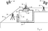
- In
Figures 1a and1b a building site is shown, as it is generally known in the art. The building site comprises abuilding 30 that is under construction and awall element 20 that is to be positioned on thebuilding 30 by means of acrane 60. Instead of a building, the construction can of course also be or comprise infrastructure such as roads or railways. - As shown in
Figure 1a , for craning, theelement 20 can be fixed to agear 62 of thecrane 60. It is then moved by thecrane 60 which is operated by a crane operator (not shown) towards a mountingposition 32 on thebuilding 30 to be mounted e. g. next to an already existingwall element 31. InFigure 1b , theelement 20 has arrived at thebuilding 30 near the mounting position. Twoconstruction workers 8 move theelement 20 manually to the mounting position in order to mount it next to the already existingwall element 31 and onfixings 36 of thebuilding 30. - In
Figure 2 an exemplary embodiment of aconstruction management system 1 according to the invention is depicted. - The
system 1 comprises acomputer system 10 with calculation means 11 and adata storage 12. The system furthermore comprises apose determination unit 2 and acrane controlling unit 3. In the shown example, thesystem 1 also comprises aconstruction measuring unit 4 and apart measuring unit 5. Thecomputer system 10 can optionally be adapted as a cluster of servers, a cloud or similar means. - The
construction measuring unit 4 and thepart measuring unit 5 are adapted to measure a construction (e. g. thebuilding 30 ofFigure 1a ) and a new part (e. g. thewall element 20 ofFigure 1a ), and to generate measurement data describing an actual state of theconstruction 74 and an actual state of thenew part 75, respectively. These as-builtdata sets data storage 12. Thedata storage 12 is adapted to provide the data, i.e. thebuilding model 72, the actual state of theconstruction 74 and the actual state of thenew part 75 to thecalculation unit 11 which comprises programme code having computer-executable instructions for calculating based on the provideddata position 32 for the new part on the construction, in particular the best-fitting mountingposition 32. Thecomputer system 10 is adapted to provide the determined mountingposition 32 to thecrane controlling unit 3. - Determining the mounting
position 32 is performed by virtual fitting and preferably also comprises determining a mounting orientation of the element at the mountingposition 32, i.e. a mounting pose is determined in six degrees of freedom. - If there are more than one new parts available for mounting, determining the mounting
position 32 may also comprise determining a sequence in which the parts are to be mounted. - The
pose determination unit 2 is adapted to determine apose 26 of the new part, i.e. its position and orientation in six degrees of freedom, while the part is being craned by means of the crane. Pose data comprising information about thedetermined pose 26 is generated and provided to thecrane controlling unit 3 in real time. - The
crane controlling unit 3 is adapted to use the mountingposition 32 provided by thecomputer system 10 and the pose data provided by thepose determination unit 2 in real time to generatemovement instructions 63 for the crane. Themovement instructions 63 may comprise an optimal movement path for the new part to the mountingposition 32. - The
crane controlling unit 3 is preferably provided at the crane. It may comprise a display and be adapted to visually provide themovement instructions 63 to an operator of the crane, or be adapted to automatically control the crane based on themovement instructions 63. If the crane is operated by an operator not located in the crane 60 (e. g. the operator controlling the crane from the mounting position), thecrane controlling unit 3 can also be adapted as a handheld device or provide themovement instructions 63 to a handheld device. - Instead of a crane, of course also other heavy lifting machines can be used that are adapted to position a building element at a mounting position. Such heavy lifting machines comprise forklift trucks as well as manned or unmanned aerial vehicles, such as helicopters or airships.
- In the
Figures 3 to 7 , exemplary embodiments of a pose determining unit of a construction management system according to the invention are shown, the pose determining units determining the pose of the wall element shown inFigures 1a and1b in six degrees of freedom by means of a GNSS system or by means of at least one surveying device. Figure 3 shows the situation ofFigure 1a , wherein a pose determining unit is provided for determining the pose of thewall element 20 while it is suspended from thecrane 60 and moved towards the mountingposition 32 on thebuilding 30. The pose determining unit comprises twoGNSS antennas 42 each of which being adapted to work with a global navigation satellite system (GNSS, represented by satellites 40), such as e. g. GPS, for determining a position of theGNSS antenna 42. In this embodiment, theGNSS antennae 42 are placed directly on theelement 20 to allow determining a position and orientation of theelement 20. The pose determining unit comprises a calculation unit (not shown) which receives position data from theGNSS antennas 42 in real time, indicating the positions of theGNSS antennas 42 in a global coordinate system and calculates a pose of theelement 20. Pose data is then transmitted to a crane controlling unit for controlling thecrane 60.- In the embodiment of
Figure 4 , the pose determining unit furthermore comprises fixedGNSS antennas 43 that are placed on thebuilding 30. The calculation unit receives position data also from these fixedGNSS antennas 43 in real time, and is adapted to compare the position data with that from themovable GNSS antennas 42 on theelement 20. This allows determining a movement of theelement 20 with higher precision than in a configuration in which only the positions of themovable GNSS antennas 42 is determined. - In the embodiment of
Figure 5 , the pose determining unit comprisesadditional GNSS antennas 41 that are placed on thecrane 60, e. g. on the crane boom (as shown here) and on a crane tower (not shown). Additionally, themovable GNSS antennas 42 are installed on thecrane gear 62 instead of being connected directly to the cranedelement 20. Figure 6 shows another embodiment of the pose determining unit comprising twosurveying devices 50. These can be adapted as theodolites and measure distances and angles toretroreflectors 52 that are provided on theelement 20 or thegear 62 at known positions.- In
Figure 7 , thesurveying devices 50 comprise a camera, and a retroreflector is provided on thegear 62 as a part of a measuringaid 55 that comprises features which are arranged and identifiable in an image of the cameras to allow determining an orientation of the measuringaid 55 and thus of thegear 62 and theelement 20 in three rotational degrees of freedom. For determining the pose of the element in this manner, onesurveying device 50 is sufficient. Optionally, the at least onesurveying device 50 is adapted as a laser tracker providing a tracking functionality for tracking the retroreflector and a camera for determining the orientation of the measuringaid 55. - Alternatively or additionally, an articulated arm CMM can be provided to measure the pose of the element directly at the mounting
position 32 with high precision. It can be provided on thebuilding 30, positioned on a base of the CMM near the mountingposition 32. A first end of an articulated arm is connected to the base, and a second end connects to a predetermined point of theelement 20. The CMM may comprise a probe, in particular a tactile probe, for measuring a position of a point relative to the base. Thus the probe, by touching the predetermined point of theelement 20 with a probe, can determine the relative position of said point. Optionally, the probe is adapted to determine an orientation of a surface at the point, thus allowing determining a relative orientation of the element 20 (6dof probe). Alternatively, the CMM can be provided on theelement 20 or on thegear 62, likewise touching a predetermined point of thebuilding 30. Optionally, two or more CMM can be used for determining positions of two or more points, thus allowing determining an orientation. - Preferably, the second end of the articulated arm is fixedly attached to the point until the element is mounted 20. A connector can be positioned at the predetermined point that is adapted to connect to the arm. Alternatively, the arm can be adapted to connect to a feature or a surface of the
element 20. - The probe or the second end of the arm can be attached manually. Alternatively, if the articulated arm can be actuated by means of a motor, by means of the
surveying devices 50, theelement 20 and/or the arm can be guided so that touching the point with the probe or arm end and establishing the connection can occur automatically. Figure 8 shows the positioning of theelement 20 at the mountingposition 32, where aworker 8 mounts theelement 20 next to an existingelement 31 on providedfixings 36. The pose determining unit in this embodiment comprisesGNSS antennas 42 that are installed on thecrane gear 62 and adapted to determine a pose of theelement 20 by using position data obtained by means of aGNSS 40. The pose determining unit further comprises two surveying devices 50 (e. g. laser trackers) that are placed on thebuilding 30 and adapted to determine a 6dof-pose of theelement 20 by measuring a distance to a retroreflector of a measuringaid 55 that is installed on thecrane gear 62 and by detecting the features of the measuringaid 55 in an image of a camera of thesurveying devices 50.- The pose of the
element 20 needs to be determined with a higher accuracy than a mounting tolerance for theelement 20 at the mountingposition 32. A typical mounting tolerance is e. g. two millimetres per metre. At least onesurveying device 50 is therefore preferably positioned not too far away from the mountingposition 32 and adapted to determine the pose with sufficient accuracy (e. g. in the sub-millimetre range). Such a surveying device might also be adapted as an articulated arm coordinate measuring machine that is positioned at the mountingposition 32. - While being craned, the
element 20 may not be in a surveying area of thesurveying devices 50 all the time, i.e. positioned so that the measuringaid 55 can be seen by thesurveying devices 50, so that a pose of theelement 20 cannot be determined by means of thesurveying devices 50 throughout the complete craning operation. Thus, theGNSS antennas 42 can provide a position and optionally also an orientation while theelement 20 and the measuringaid 55 are outside said surveying area. - As a three-dimensional model of an actual construction state of the
building 30 is available and the positions of thesurveying devices 50 are known, it is possible to determine the borders of the surveying area. Using the position provided by theGNSS antennas 42 it is thus possible to generate movement instructions for guiding theelement 20 into the surveying area. - A position and orientation of the
element 20 needs to be determined with high precision and in six degrees of freedom only when theelement 20 has almost reached its determined mounting position 32 (or mounting pose). Therefore, the position and orientation of theelement 20 optionally can be determined with increasing accuracy as the element approaches the mountingposition 32. - Also, while the
element 20 is still far away from the mountingposition 32, for generating the movement instructions it is possible to determine only the position of the element 20 - or the position and less than three rotational degrees of freedom. In this case, a highly precise 6dof-measurement of the element's pose can be started e. g. when a determined distance of theelement 20 falls below a threshold value. - Optionally, the movement instructions can be provided to
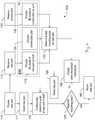
workers 8 at the mounting position together with information about the exact mounting pose and/or the determined position and orientation of theelement 20, in order to facilitate moving theelement 20 into the exact mounting pose manually. Figure 9 is a flow chart illustrating amethod 100 according to the invention. In a first step 110 a new part to be mounted to a construction is provided. It is then measured 112, e. g. by means of a laser scanner, so that a 3D as-built model of the part is provided 115 as a part of a building information model (BIM) 70. Likewise, the construction is measured 122, in particular by means of one or more laser scanners. A 3D as-built model of the construction is then provided 125 as a part of theBIM 70. As a part of theBIM 70 also a construction plan is provided 120, comprising a target state of the construction. Using the information provided by theBIM 70, i.e. the construction plan and the 3D as-built models of the construction and the new part, the best mounting pose for the new part is determined 130. The best mounting pose comprises a mounting position and mounting orientation of the part in six degrees of freedom at which the part is to be mounted to the existing construction, in view of the original plan and the as-built state.- The new part is then craned 111, i.e. attached to a crane and lifted by the crane, suspended from a boom of the crane, wherein the crane is positioned and adapted to move the part to the mounting pose determined in
step 130. - In
step 140 the pose of the part is then determined continuously in six degrees of freedom while the part is craned and moved towards said mounting position. The pose is determined relative to the mounting position. This is done either directly, e. g. in such a way that the mounting position marks the point of origin of a common local coordinate system, or indirectly, e. g. in such a way that the pose and the mounting position, both, are assigned coordinates in a global or local coordinate system. - The pose of the part is compared with the mounting pose in
step 145. If the poses are identical, the new part is mounted 160 to the building. If they are not identical, crane movement instructions are created 150 based on the mounting pose determined instep 130 and on the continuously determined pose of the part ofstep 140. Thiscreation 150 of movement instructions occurs in real time and without more delay from thepose detection 140 of the part than technically necessary. - The crane is then moved 155 according to the crane movement instructions, thus changing the pose of the craned part, which is then determined again is
step 140. The crane can be moved automatically based on the movement instructions, or the movement instructions are provided to a human operator of the crane, e. g. visually on a screen. - This loop is continued until the poses are determined to be identical in
step 145 and the part is mounted 160. Additionally, the movement instructions can be provided to workers mounting the element, in order to allow them to move the element into the mounting position manually with high precision. - Although the invention is illustrated above, partly with reference to some preferred embodiments, it must be understood that numerous modifications and combinations of different features of the embodiments can be made, within the scope of the appended claims.
Claims (15)
- Construction management system (1) for the construction of a building (30) wherein at least one heavy lifting machine (60), particularly a crane, is used for moving at least one building element (20) to a mounting position (32) on the building (30), the system comprising a central computing unit (10) with calculation means (11) and a data storage (12), the central computing unit (10) providing a building information model (70) comprising at least- a construction plan (72) comprising a target state of the construction of the building (30),- a three-dimensional model (74) of an actual construction state of the building (30), and- a three-dimensional model (75) of the element (20), wherein the central computing unit (10) is adapted to determine the mounting position (32) for the element (20) based on the construction plan (72), on the model (74) of the current construction state and on the model (75) of the element (20), and wherein the system (1) comprises- a machine controlling unit (3) that is adapted to generate movement information to allow moving the element (20) to the mounting position (32) by means of the at least one lifting machine (60), and- a pose determining unit (2) that is adapted to▪ determine, in real time and in six degrees of freedom, a position and orientation (26) of the element (20) while it is lifted by means of the lifting machine (60),▪ generate pose data based on the determined position and orientation (26) of the element (20), and▪ provide the pose data to the machine controlling unit (3) in real time,wherein the machine controlling unit (3) is adapted to generate the movement information in real time based on the pose data,
characterized in that
the pose determining unit (2) is adapted to monitor a distance of the element (20) to the mounting position (32) and to determine the position and orientation (26) of the element (20) in six degrees of freedom only when the distance is below a pre-defined threshold value, the threshold value depending on a size of the element (20). - Construction management system (1) according to claim 1,
characterized in that
the central computing unit (10) is adapted to determine a mounting pose of the element (20) based on the construction plan (72), on the model (74) of the current construction state and on the model (75) of the element (20), the mounting pose comprising the mounting position (32) and a mounting orientation, particularly wherein the movement information comprises information about- a position of the element (20) relative to the mounting position (32) and- an orientation of the element (20) relative to the mounting orientation. - Construction management system (1) according to claim 2,
characterized in that
the pose determining unit (2) comprises at least one articulated arm coordinate measuring machine, particularly at least two articulated arm coordinate measuring machines, adapted to determine, at the mounting position (32),- a position of the element (20) relative to the mounting position (32) and- an orientation of the element (20) relative to the mounting orientation,particularly wherein the articulated arm is connectable with a first end to a defined point of the building (30) and with a second end to a defined point of the element (20). - Construction management system (1) according to any one of the preceding claims,
characterized in that- the central computing unit (10) is adapted to determine a movement path from a determined position of the element (20) to the mounting position (32), and- the movement information comprises movement instructions (63) for moving the element (20) along the movement path,
wherein the machine controlling unit (3)- is adapted to automatically control the lifting machine (60) based on the movement instructions (63), and/or- comprises a display and is adapted to visually provide the movement instructions (63) to an operator of the lifting machine (60),
in particular wherein the lifting machine (60) is- a crane, particularly a mobile crane or tower crane,- a forklift truck, or- a manned or unmanned aerial vehicle, particularly a helicopter or an airship. - Construction management system (1) according to any one of the preceding claims,
characterized by
the machine controlling unit (3) is adapted to provide the movement information to a user at the mounting position (32), particularly wherein- the user is an operator of the lifting machine (60), operating the lifting machine (60) from the mounting position (32), and/or- the machine controlling unit (3) is adapted to provide the movement information to a field device comprising a display and being adapted to visually provide the movement information to the user. - Construction management system (1) according to any one of the preceding claims,
characterized by
survey instruments, particularly comprising laser scanners, the survey instruments being adapted to provide- the three-dimensional model of the actual construction state of the building (30), and/or- the three-dimensional model of the element (20). - Construction management system (1) according to any one of the preceding claims,
characterized in that
the pose determining unit (2) comprises at least one movable GNSS device (42) attachable to the element (20) and/or to a first part (62) of the lifting machine (60) to which the element (20) is fixed during lifting, in particular at least two movable GNSS devices (42), providing first GNSS data indicating a position of the respective GNSS device (42). - Construction management system (1) according to claim 7,
characterized in that
the pose determining unit (2)- comprises at least one stationary GNSS device (43), in particular at least two stationary GNSS devices (43), providing stationary GNSS data, and- is adapted to determine at least the position of the element (20) based on the first GNSS data and on the stationary GNSS data. - Construction management system (1) according to any one of the preceding claims,
characterized in that
the pose determining unit (2) comprises at least one surveying device (50), in particular at least two surveying devices (50), being adapted to determine, in three positional degrees of freedom, a position of a retroreflector (52) that is attached to the element (20) and/or to a first part (62) of the lifting machine (60) to which the element (20) is fixed during craning, providing surveying data indicating the position and orientation (26) of the element (20), particularly wherein the at least one surveying device (50)- is adapted to track the retroreflector (52), and/or- has a camera adapted to continuously capture images of a measuring aid (55) comprising the retroreflector (52) and features that are arranged and identifiable in the image of the camera to allow determining an orientation in three rotational degrees of freedom. - Method (100) for positioning a building element (20) at a mounting position (32) of a building (30) by means of a heavy lifting machine (60), particularly using a construction management system (1) according to any one of the preceding claims, the method (100) comprising- providing (115, 120, 125) a building information model (70) comprising at least▪ a construction plan (72) comprising a target state of the construction of the building (30),▪ a three-dimensional model (74) of a current construction state of the building (30), and▪ a three-dimensional model (75) of the element (20),- determining (130) the mounting position (32) for the element (20) based on the construction plan (72), on the model (74) of the current construction state and on the model (75) of the element (20),- lifting (111) the element (20) by means of the lifting machine (60),- determining (140), in real time and in six degrees of freedom, a position and orientation (26) of the element (20) while being lifted,- generating pose data based on the determined position and orientation (26) of the element (20),- generating (150) movement information in real time based on the pose data, and- moving (155), by means of the lifting machine (60), the element (20) to the mounting position (32) according to the movement information,
characterized in that- a distance of the element (20) to the mounting position (32) is monitored, and- the position and orientation (26) of the element (20) is determined (140) in six degrees of freedom only when the distance is below a threshold value, the threshold value depending on a size of the element (20). - Method (100) according to claim 10,
characterized in that
determining (130) the mounting position (32) comprises predicting dimensional changes of the element (20) and/or of fittings (36) for connecting the element (20) to the building (30), said changes occurring during moving (155) the element and/or after mounting (160) the element (20). - Method (100) according to claim 10 or claim 11,
characterized in that- the position and orientation (26) of the element (20) is determined (140) with increasing accuracy as the element approaches the mounting position (32), and/or- the position and orientation (26) of the element (20) is determined by means of an articulated arm coordinate measuring machine that is positioned at the mounting position (32). - Method (100) according to any one of claims 10 to 12,
characterized in that
determining (140) the position and orientation (26) of the element (20) comprises determining by means of at least one surveying device (50), in particular at least two surveying devices (50), a position of a retroreflector (52) that is attached to the element (20) and/or to a first part (62) of the lifting machine (60) to which the element (20) is fixed during lifting, particularly wherein- the lifting machine (60) is a crane and the first part (62) is a crane gear, and/or- the retroreflector is tracked by the at least one surveying device (50). - Method (100) according to claim 13,
characterized in that
the at least one surveying device (50) has a surveying area in which the position and orientation (26) of the element (20) is determinable, wherein the method comprises moving the element (20) into the surveying area, wherein- the surveying area is determined based on the three-dimensional model of the current construction state of the building (30), and/or- a position of the element (20) is determined by means of a GNSS device (42) when the element (20) is not in the surveying area. - Computer programme product comprising programme code which is stored on a machine-readable medium, and having computer-executable instructions for performing, when run on calculation means of a construction management system according to any one of claims 1 to 9, at least the following steps of the method according to one of the claims 10 to 14:- determining (140), in real time and in six degrees of freedom, a position and orientation (26) of the element (20) while it is lifted (111),- generating pose data based on the determined position and orientation (26) of the element (20),- generating (150) movement information in real time based on the pose data, and- monitoring a distance of the element (20) to the mounting position (32),wherein the position and orientation (26) of the element (20) is determined (140) in six degrees of freedom only when the distance is below a threshold value, the threshold value depending on a size of the element (20).
Priority Applications (3)
| Application Number | Priority Date | Filing Date | Title |
|---|---|---|---|
| EP17152513.2AEP3351699B1 (en) | 2017-01-20 | 2017-01-20 | Construction management system and method |
| CN201810052697.5ACN108334678B (en) | 2017-01-20 | 2018-01-19 | Construction management system and method of positioning building components at installation locations |
| US15/875,986US10876307B2 (en) | 2017-01-20 | 2018-01-19 | Construction management system and method |
Applications Claiming Priority (1)
| Application Number | Priority Date | Filing Date | Title |
|---|---|---|---|
| EP17152513.2AEP3351699B1 (en) | 2017-01-20 | 2017-01-20 | Construction management system and method |
Publications (2)
| Publication Number | Publication Date |
|---|---|
| EP3351699A1 EP3351699A1 (en) | 2018-07-25 |
| EP3351699B1true EP3351699B1 (en) | 2020-12-09 |
Family
ID=57868119
Family Applications (1)
| Application Number | Title | Priority Date | Filing Date |
|---|---|---|---|
| EP17152513.2AActiveEP3351699B1 (en) | 2017-01-20 | 2017-01-20 | Construction management system and method |
Country Status (3)
| Country | Link |
|---|---|
| US (1) | US10876307B2 (en) |
| EP (1) | EP3351699B1 (en) |
| CN (1) | CN108334678B (en) |
Families Citing this family (34)
| Publication number | Priority date | Publication date | Assignee | Title |
|---|---|---|---|---|
| ES2899284T3 (en) | 2016-07-15 | 2022-03-10 | Fastbrick Ip Pty Ltd | Vehicle incorporating a brick laying machine |
| ES2899585T3 (en) | 2016-07-15 | 2022-03-14 | Fastbrick Ip Pty Ltd | Material transport boom |
| US11130658B2 (en) | 2016-11-22 | 2021-09-28 | Manitowoc Crane Companies, Llc | Optical detection and analysis of a counterweight assembly on a crane |
| WO2019006511A1 (en) | 2017-07-05 | 2019-01-10 | Fastbrick Ip Pty Ltd | Real time position and orientation tracker |
| CN111213098B (en) | 2017-08-17 | 2024-03-15 | 快砖知识产权私人有限公司 | Communication systems for interactive systems |
| WO2019033170A1 (en) | 2017-08-17 | 2019-02-21 | Fastbrick Ip Pty Ltd | Laser tracker with improved roll angle measurement |
| CN111212799B (en) | 2017-10-11 | 2023-04-14 | 快砖知识产权私人有限公司 | Machine for conveying objects and multi-compartment carousel for use therewith |
| JP7172199B2 (en)* | 2018-07-05 | 2022-11-16 | 株式会社タダノ | Remote control terminal and work vehicle |
| CN112689552A (en) | 2018-07-16 | 2021-04-20 | 快砖知识产权私人有限公司 | Active damping system |
| US12214500B2 (en) | 2018-07-16 | 2025-02-04 | Fastbrick Ip Pty Ltd | Backup tracking for an interaction system |
| US20200034766A1 (en)* | 2018-07-27 | 2020-01-30 | Gabriel Borges | System and method to increase productivity |
| US12358763B2 (en) | 2018-11-07 | 2025-07-15 | Manitowoc Crane Companies, Llc | System for determining crane status using optical and/or electromagnetic sensors |
| CN109823968A (en)* | 2018-12-21 | 2019-05-31 | 佛山市诚德新材料有限公司 | A kind of overhead traveling crane reservoir region management system |
| CN109826314B (en)* | 2019-01-31 | 2021-03-02 | 重庆建筑工程职业学院 | Installation method of fabricated building |
| EP3705661A1 (en) | 2019-03-05 | 2020-09-09 | Umdasch Group NewCon GmbH | Method and system for determining position of a formwork |
| CN110127079B (en)* | 2019-04-11 | 2020-11-06 | 上海卫星工程研究所 | Target flight characteristic simulation system under remote sensing visual field based on six-degree-of-freedom platform |
| JP7293885B2 (en)* | 2019-06-05 | 2023-06-20 | 株式会社タダノ | load direction control system |
| JP7452112B2 (en) | 2020-03-09 | 2024-03-19 | 株式会社タダノ | Control device, terminal, and calculation method |
| JP7376419B2 (en)* | 2020-04-14 | 2023-11-08 | 戸田建設株式会社 | Automatic angle control system for tower crane lifting loads |
| US12385265B2 (en) | 2020-04-22 | 2025-08-12 | Fastbrick Ip Pty Ltd | Block transfer apparatus and improved clamping assembly for use therewith |
| CN111550062A (en)* | 2020-06-01 | 2020-08-18 | 中建七局第二建筑有限公司 | Hoisting steel frame design method applied to field of building curtain wall |
| CN111540267B (en)* | 2020-06-19 | 2021-10-12 | 山东省城镇规划建筑设计院有限公司 | Architectural model inner structure display device for architectural design |
| EP4179172A4 (en) | 2020-07-08 | 2024-08-07 | Fastbrick IP Pty Ltd | ADHESIVE APPLICATION SYSTEM |
| CN112064825B (en)* | 2020-07-24 | 2021-09-28 | 安徽同济建设集团有限责任公司 | Construction method of basement stair firewall |
| US20220154480A1 (en)* | 2020-11-16 | 2022-05-19 | Ip Factors, Llc | Integrated component-based construction components and related methods |
| CA3197017A1 (en)* | 2020-11-27 | 2022-06-02 | Sho TAGO | Construction information integration system, construction information integration method, and construction information integration program |
| US11727173B2 (en) | 2020-12-16 | 2023-08-15 | Lendlease Digital IP Pty Limited | System and method for automatically generating an optimized building floor plate layout |
| CN112799435B (en)* | 2020-12-31 | 2022-08-05 | 海门市帕源路桥建设有限公司 | Intelligent machine control method for mounting and dismounting bottom plate low wall formwork |
| CN112854739B (en)* | 2021-01-04 | 2022-06-03 | 海门市帕源路桥建设有限公司 | Automatic control and regulation system for bottom plate short wall formwork |
| CN113428785A (en)* | 2021-06-22 | 2021-09-24 | 筑友智造建设科技集团有限公司 | Hoisting positioning method, device and equipment for construction site component and storage medium |
| JP7709025B2 (en)* | 2021-07-16 | 2025-07-16 | 三協立山株式会社 | Window Installation System |
| CN114491728A (en)* | 2021-12-13 | 2022-05-13 | 中建五局安装工程有限公司 | An information management construction method and system |
| KR102692624B1 (en)* | 2022-10-19 | 2024-08-06 | 주식회사 승인디에프에스 | Auxiliary drone for lifting steel structures |
| CN118308984B (en)* | 2024-06-07 | 2024-10-22 | 中国电建集团西北勘测设计研究院有限公司 | Method and system for installing special-shaped aluminum structure |
Family Cites Families (24)
| Publication number | Priority date | Publication date | Assignee | Title |
|---|---|---|---|---|
| US5267143A (en)* | 1984-10-12 | 1993-11-30 | Sensor Adaptive Machines, Incorporated | Vision assisted fixture construction |
| CA2522097C (en) | 2003-04-28 | 2012-09-25 | Stephen James Crampton | Cmm arm with exoskeleton |
| EP2108917B1 (en) | 2008-04-07 | 2012-10-03 | Leica Geosystems AG | Articulated arm coordinate measuring machine |
| US8082673B2 (en) | 2009-11-06 | 2011-12-27 | Hexagon Metrology Ab | Systems and methods for control and calibration of a CMM |
| WO2012171138A1 (en) | 2011-06-14 | 2012-12-20 | Metrologic Instruments, Inc. | Camera registration and video integration in 3-d geometry model |
| US9222771B2 (en)* | 2011-10-17 | 2015-12-29 | Kla-Tencor Corp. | Acquisition of information for a construction site |
| US20140365259A1 (en)* | 2011-11-29 | 2014-12-11 | Trimble Navigation Limited | In-field installation record of a project |
| JP5576455B2 (en) | 2012-02-20 | 2014-08-20 | ソリデオ システムズ カンパニー リミテッド | Method for providing data contained in BIM data file, recording medium recording the same, and system including the same |
| EP2717181A1 (en) | 2012-10-08 | 2014-04-09 | Hexagon Technology Center GmbH | Method and system for virtual assembly of a structure |
| JP5489310B1 (en) | 2012-12-20 | 2014-05-14 | 東芝エレベータ株式会社 | BIM system and method |
| US9121692B2 (en) | 2013-03-13 | 2015-09-01 | Trimble Navigation Limited | Method and apparatus for projection of BIM information |
| WO2015053711A1 (en)* | 2013-10-08 | 2015-04-16 | Nanyang Technological University | Method and system for intelligent crane lifting |
| CN103778321A (en)* | 2014-01-02 | 2014-05-07 | 彭雪鹏 | Method for analyzing wind action dynamic performance of super high-rise building swing-arm tower crane |
| CN103886139A (en) | 2014-02-27 | 2014-06-25 | 上海蓝色星球科技有限公司 | Event interaction method based on building information model (BIM) |
| EP2916099B1 (en)* | 2014-03-07 | 2020-09-30 | Hexagon Technology Center GmbH | Articulated arm coordinate measuring machine |
| CN104951581B (en)* | 2014-03-31 | 2018-07-10 | 中国石油天然气股份有限公司 | Equipment installation construction scheme simulation verification method and device based on CAM platform |
| DE102014104712B4 (en)* | 2014-04-02 | 2020-07-30 | Faro Technologies, Inc. | Registration of a scene disintegrating into clusters with visualized clusters |
| EP2980526B1 (en) | 2014-07-30 | 2019-01-16 | Leica Geosystems AG | Coordinate measuring device and method |
| US20160031680A1 (en)* | 2014-07-31 | 2016-02-04 | Trimble Navigation Limited | Crane productivity coordination |
| NL2013409B1 (en)* | 2014-09-03 | 2016-09-27 | Fugro N V | Spatial positioning of offshore structures. |
| EP3054404A1 (en)* | 2015-02-04 | 2016-08-10 | Hexagon Technology Center GmbH | Work information modelling |
| CN105069182B (en)* | 2015-07-07 | 2019-06-28 | 中冶建筑研究总院有限公司 | Method for monitoring the tired service life of crane girder |
| EP3165945B1 (en)* | 2015-11-03 | 2024-01-03 | Leica Geosystems AG | Surface measuring device for determining the 3d coordinates of a surface |
| CN105731262B (en)* | 2016-04-01 | 2018-02-06 | 中国建筑第八工程局有限公司 | Plane layout of tower crane system and method based on BIM technology |
- 2017
- 2017-01-20EPEP17152513.2Apatent/EP3351699B1/enactiveActive
- 2018
- 2018-01-19CNCN201810052697.5Apatent/CN108334678B/enactiveActive
- 2018-01-19USUS15/875,986patent/US10876307B2/enactiveActive
Non-Patent Citations (1)
| Title |
|---|
| None* |
Also Published As
| Publication number | Publication date |
|---|---|
| US20180209156A1 (en) | 2018-07-26 |
| EP3351699A1 (en) | 2018-07-25 |
| CN108334678B (en) | 2021-10-26 |
| CN108334678A (en) | 2018-07-27 |
| US10876307B2 (en) | 2020-12-29 |
Similar Documents
| Publication | Publication Date | Title |
|---|---|---|
| US10876307B2 (en) | Construction management system and method | |
| US8060344B2 (en) | Method and system for automatically performing a study of a multidimensional space | |
| US11253991B1 (en) | Optimization of observer robot locations | |
| EP2869024B1 (en) | Three-dimensional measuring method and surveying system | |
| JP6594686B2 (en) | Three-dimensional shape measuring apparatus, three-dimensional shape measuring method, and program | |
| EP2972084B1 (en) | System and method for positioning a tool in a work space | |
| CN110857591B (en) | Measuring and/or marking device, method and system for determining the installation area of a device | |
| CN114585875A (en) | Metering system | |
| JP4950348B2 (en) | Information providing apparatus, information providing method, and program | |
| CN111693030B (en) | System for improving automatic control of machine operation of a construction site machine | |
| JP2000275045A (en) | Automated guiding and measuring device and method for measuring and navigating freely movable platform | |
| JP2010540796A (en) | System and method capable of navigating and / or mapping multidimensional space | |
| CN108132476A (en) | A kind of engineering machinery hopper alignment system and method | |
| JP2023130558A (en) | Survey support system, information display terminal, method for supporting survey, and survey support program | |
| US11499297B2 (en) | Measuring arrangement for measuring three dimensional location and orientation of the center axis of first axle in relation to the center axis of second axle | |
| US20240310842A1 (en) | Work Machine | |
| EP4112824B1 (en) | Measuring system, measuring method, and measuring program for determining the positions of the site resources at a construction site | |
| CN215881648U (en) | Mobile brick laying robot system for building construction | |
| EP3943979A1 (en) | Indoor device localization | |
| KR20230049358A (en) | Device and method for deriving location of swarm flying drones | |
| CN112792825A (en) | A mobile brick laying robot system and control method for building construction | |
| US12197236B2 (en) | System, apparatus, and method for providing augmented reality assistance to wayfinding and precision landing controls of an unmanned aerial vehicle to differently oriented inspection targets | |
| EP4589255A1 (en) | Rover orientation measurement for surveying tilt compensation | |
| US20250224231A1 (en) | System and method for enabling mixed reality on mobile devices in a construction site |
Legal Events
| Date | Code | Title | Description |
|---|---|---|---|
| PUAI | Public reference made under article 153(3) epc to a published international application that has entered the european phase | Free format text:ORIGINAL CODE: 0009012 | |
| STAA | Information on the status of an ep patent application or granted ep patent | Free format text:STATUS: THE APPLICATION HAS BEEN PUBLISHED | |
| AK | Designated contracting states | Kind code of ref document:A1 Designated state(s):AL AT BE BG CH CY CZ DE DK EE ES FI FR GB GR HR HU IE IS IT LI LT LU LV MC MK MT NL NO PL PT RO RS SE SI SK SM TR | |
| AX | Request for extension of the european patent | Extension state:BA ME | |
| STAA | Information on the status of an ep patent application or granted ep patent | Free format text:STATUS: REQUEST FOR EXAMINATION WAS MADE | |
| 17P | Request for examination filed | Effective date:20190121 | |
| RBV | Designated contracting states (corrected) | Designated state(s):AL AT BE BG CH CY CZ DE DK EE ES FI FR GB GR HR HU IE IS IT LI LT LU LV MC MK MT NL NO PL PT RO RS SE SI SK SM TR | |
| RIN1 | Information on inventor provided before grant (corrected) | Inventor name:PETTERSSON, BO | |
| STAA | Information on the status of an ep patent application or granted ep patent | Free format text:STATUS: EXAMINATION IS IN PROGRESS | |
| 17Q | First examination report despatched | Effective date:20200313 | |
| GRAP | Despatch of communication of intention to grant a patent | Free format text:ORIGINAL CODE: EPIDOSNIGR1 | |
| STAA | Information on the status of an ep patent application or granted ep patent | Free format text:STATUS: GRANT OF PATENT IS INTENDED | |
| RIC1 | Information provided on ipc code assigned before grant | Ipc:E04B 1/35 20060101AFI20200701BHEP Ipc:G06Q 10/06 20120101ALI20200701BHEP Ipc:B66C 13/48 20060101ALI20200701BHEP Ipc:G09B 25/04 20060101ALI20200701BHEP Ipc:G06Q 50/08 20120101ALI20200701BHEP Ipc:G09B 9/04 20060101ALI20200701BHEP Ipc:G09B 19/16 20060101ALI20200701BHEP | |
| INTG | Intention to grant announced | Effective date:20200803 | |
| GRAS | Grant fee paid | Free format text:ORIGINAL CODE: EPIDOSNIGR3 | |
| GRAA | (expected) grant | Free format text:ORIGINAL CODE: 0009210 | |
| STAA | Information on the status of an ep patent application or granted ep patent | Free format text:STATUS: THE PATENT HAS BEEN GRANTED | |
| AK | Designated contracting states | Kind code of ref document:B1 Designated state(s):AL AT BE BG CH CY CZ DE DK EE ES FI FR GB GR HR HU IE IS IT LI LT LU LV MC MK MT NL NO PL PT RO RS SE SI SK SM TR | |
| REG | Reference to a national code | Ref country code:GB Ref legal event code:FG4D | |
| REG | Reference to a national code | Ref country code:AT Ref legal event code:REF Ref document number:1343591 Country of ref document:AT Kind code of ref document:T Effective date:20201215 Ref country code:CH Ref legal event code:EP | |
| REG | Reference to a national code | Ref country code:DE Ref legal event code:R096 Ref document number:602017029081 Country of ref document:DE | |
| REG | Reference to a national code | Ref country code:IE Ref legal event code:FG4D | |
| REG | Reference to a national code | Ref country code:CH Ref legal event code:NV Representative=s name:KAMINSKI HARMANN PATENTANWAELTE AG, LI | |
| REG | Reference to a national code | Ref country code:SE Ref legal event code:TRGR | |
| PG25 | Lapsed in a contracting state [announced via postgrant information from national office to epo] | Ref country code:NO Free format text:LAPSE BECAUSE OF FAILURE TO SUBMIT A TRANSLATION OF THE DESCRIPTION OR TO PAY THE FEE WITHIN THE PRESCRIBED TIME-LIMIT Effective date:20210309 Ref country code:RS Free format text:LAPSE BECAUSE OF FAILURE TO SUBMIT A TRANSLATION OF THE DESCRIPTION OR TO PAY THE FEE WITHIN THE PRESCRIBED TIME-LIMIT Effective date:20201209 Ref country code:FI Free format text:LAPSE BECAUSE OF FAILURE TO SUBMIT A TRANSLATION OF THE DESCRIPTION OR TO PAY THE FEE WITHIN THE PRESCRIBED TIME-LIMIT Effective date:20201209 Ref country code:GR Free format text:LAPSE BECAUSE OF FAILURE TO SUBMIT A TRANSLATION OF THE DESCRIPTION OR TO PAY THE FEE WITHIN THE PRESCRIBED TIME-LIMIT Effective date:20210310 | |
| REG | Reference to a national code | Ref country code:AT Ref legal event code:MK05 Ref document number:1343591 Country of ref document:AT Kind code of ref document:T Effective date:20201209 | |
| PG25 | Lapsed in a contracting state [announced via postgrant information from national office to epo] | Ref country code:BG Free format text:LAPSE BECAUSE OF FAILURE TO SUBMIT A TRANSLATION OF THE DESCRIPTION OR TO PAY THE FEE WITHIN THE PRESCRIBED TIME-LIMIT Effective date:20210309 Ref country code:LV Free format text:LAPSE BECAUSE OF FAILURE TO SUBMIT A TRANSLATION OF THE DESCRIPTION OR TO PAY THE FEE WITHIN THE PRESCRIBED TIME-LIMIT Effective date:20201209 | |
| REG | Reference to a national code | Ref country code:NL Ref legal event code:MP Effective date:20201209 | |
| PG25 | Lapsed in a contracting state [announced via postgrant information from national office to epo] | Ref country code:NL Free format text:LAPSE BECAUSE OF FAILURE TO SUBMIT A TRANSLATION OF THE DESCRIPTION OR TO PAY THE FEE WITHIN THE PRESCRIBED TIME-LIMIT Effective date:20201209 Ref country code:HR Free format text:LAPSE BECAUSE OF FAILURE TO SUBMIT A TRANSLATION OF THE DESCRIPTION OR TO PAY THE FEE WITHIN THE PRESCRIBED TIME-LIMIT Effective date:20201209 | |
| REG | Reference to a national code | Ref country code:LT Ref legal event code:MG9D | |
| PG25 | Lapsed in a contracting state [announced via postgrant information from national office to epo] | Ref country code:SK Free format text:LAPSE BECAUSE OF FAILURE TO SUBMIT A TRANSLATION OF THE DESCRIPTION OR TO PAY THE FEE WITHIN THE PRESCRIBED TIME-LIMIT Effective date:20201209 Ref country code:PT Free format text:LAPSE BECAUSE OF FAILURE TO SUBMIT A TRANSLATION OF THE DESCRIPTION OR TO PAY THE FEE WITHIN THE PRESCRIBED TIME-LIMIT Effective date:20210409 Ref country code:RO Free format text:LAPSE BECAUSE OF FAILURE TO SUBMIT A TRANSLATION OF THE DESCRIPTION OR TO PAY THE FEE WITHIN THE PRESCRIBED TIME-LIMIT Effective date:20201209 Ref country code:CZ Free format text:LAPSE BECAUSE OF FAILURE TO SUBMIT A TRANSLATION OF THE DESCRIPTION OR TO PAY THE FEE WITHIN THE PRESCRIBED TIME-LIMIT Effective date:20201209 Ref country code:EE Free format text:LAPSE BECAUSE OF FAILURE TO SUBMIT A TRANSLATION OF THE DESCRIPTION OR TO PAY THE FEE WITHIN THE PRESCRIBED TIME-LIMIT Effective date:20201209 Ref country code:SM Free format text:LAPSE BECAUSE OF FAILURE TO SUBMIT A TRANSLATION OF THE DESCRIPTION OR TO PAY THE FEE WITHIN THE PRESCRIBED TIME-LIMIT Effective date:20201209 Ref country code:LT Free format text:LAPSE BECAUSE OF FAILURE TO SUBMIT A TRANSLATION OF THE DESCRIPTION OR TO PAY THE FEE WITHIN THE PRESCRIBED TIME-LIMIT Effective date:20201209 | |
| PG25 | Lapsed in a contracting state [announced via postgrant information from national office to epo] | Ref country code:AT Free format text:LAPSE BECAUSE OF FAILURE TO SUBMIT A TRANSLATION OF THE DESCRIPTION OR TO PAY THE FEE WITHIN THE PRESCRIBED TIME-LIMIT Effective date:20201209 Ref country code:PL Free format text:LAPSE BECAUSE OF FAILURE TO SUBMIT A TRANSLATION OF THE DESCRIPTION OR TO PAY THE FEE WITHIN THE PRESCRIBED TIME-LIMIT Effective date:20201209 | |
| REG | Reference to a national code | Ref country code:DE Ref legal event code:R097 Ref document number:602017029081 Country of ref document:DE | |
| PG25 | Lapsed in a contracting state [announced via postgrant information from national office to epo] | Ref country code:IS Free format text:LAPSE BECAUSE OF FAILURE TO SUBMIT A TRANSLATION OF THE DESCRIPTION OR TO PAY THE FEE WITHIN THE PRESCRIBED TIME-LIMIT Effective date:20210409 Ref country code:MC Free format text:LAPSE BECAUSE OF FAILURE TO SUBMIT A TRANSLATION OF THE DESCRIPTION OR TO PAY THE FEE WITHIN THE PRESCRIBED TIME-LIMIT Effective date:20201209 Ref country code:LU Free format text:LAPSE BECAUSE OF NON-PAYMENT OF DUE FEES Effective date:20210120 | |
| REG | Reference to a national code | Ref country code:BE Ref legal event code:MM Effective date:20210131 | |
| PLBE | No opposition filed within time limit | Free format text:ORIGINAL CODE: 0009261 | |
| STAA | Information on the status of an ep patent application or granted ep patent | Free format text:STATUS: NO OPPOSITION FILED WITHIN TIME LIMIT | |
| PG25 | Lapsed in a contracting state [announced via postgrant information from national office to epo] | Ref country code:AL Free format text:LAPSE BECAUSE OF FAILURE TO SUBMIT A TRANSLATION OF THE DESCRIPTION OR TO PAY THE FEE WITHIN THE PRESCRIBED TIME-LIMIT Effective date:20201209 Ref country code:IT Free format text:LAPSE BECAUSE OF FAILURE TO SUBMIT A TRANSLATION OF THE DESCRIPTION OR TO PAY THE FEE WITHIN THE PRESCRIBED TIME-LIMIT Effective date:20201209 | |
| 26N | No opposition filed | Effective date:20210910 | |
| PG25 | Lapsed in a contracting state [announced via postgrant information from national office to epo] | Ref country code:SI Free format text:LAPSE BECAUSE OF FAILURE TO SUBMIT A TRANSLATION OF THE DESCRIPTION OR TO PAY THE FEE WITHIN THE PRESCRIBED TIME-LIMIT Effective date:20201209 Ref country code:DK Free format text:LAPSE BECAUSE OF FAILURE TO SUBMIT A TRANSLATION OF THE DESCRIPTION OR TO PAY THE FEE WITHIN THE PRESCRIBED TIME-LIMIT Effective date:20201209 | |
| PG25 | Lapsed in a contracting state [announced via postgrant information from national office to epo] | Ref country code:ES Free format text:LAPSE BECAUSE OF FAILURE TO SUBMIT A TRANSLATION OF THE DESCRIPTION OR TO PAY THE FEE WITHIN THE PRESCRIBED TIME-LIMIT Effective date:20201209 Ref country code:IE Free format text:LAPSE BECAUSE OF NON-PAYMENT OF DUE FEES Effective date:20210120 | |
| PG25 | Lapsed in a contracting state [announced via postgrant information from national office to epo] | Ref country code:IS Free format text:LAPSE BECAUSE OF FAILURE TO SUBMIT A TRANSLATION OF THE DESCRIPTION OR TO PAY THE FEE WITHIN THE PRESCRIBED TIME-LIMIT Effective date:20210409 | |
| PG25 | Lapsed in a contracting state [announced via postgrant information from national office to epo] | Ref country code:BE Free format text:LAPSE BECAUSE OF NON-PAYMENT OF DUE FEES Effective date:20210131 | |
| PG25 | Lapsed in a contracting state [announced via postgrant information from national office to epo] | Ref country code:CY Free format text:LAPSE BECAUSE OF FAILURE TO SUBMIT A TRANSLATION OF THE DESCRIPTION OR TO PAY THE FEE WITHIN THE PRESCRIBED TIME-LIMIT Effective date:20201209 | |
| PG25 | Lapsed in a contracting state [announced via postgrant information from national office to epo] | Ref country code:HU Free format text:LAPSE BECAUSE OF FAILURE TO SUBMIT A TRANSLATION OF THE DESCRIPTION OR TO PAY THE FEE WITHIN THE PRESCRIBED TIME-LIMIT; INVALID AB INITIO Effective date:20170120 | |
| PG25 | Lapsed in a contracting state [announced via postgrant information from national office to epo] | Ref country code:MK Free format text:LAPSE BECAUSE OF FAILURE TO SUBMIT A TRANSLATION OF THE DESCRIPTION OR TO PAY THE FEE WITHIN THE PRESCRIBED TIME-LIMIT Effective date:20201209 | |
| PG25 | Lapsed in a contracting state [announced via postgrant information from national office to epo] | Ref country code:MT Free format text:LAPSE BECAUSE OF FAILURE TO SUBMIT A TRANSLATION OF THE DESCRIPTION OR TO PAY THE FEE WITHIN THE PRESCRIBED TIME-LIMIT Effective date:20201209 | |
| PGFP | Annual fee paid to national office [announced via postgrant information from national office to epo] | Ref country code:DE Payment date:20250121 Year of fee payment:9 | |
| PGFP | Annual fee paid to national office [announced via postgrant information from national office to epo] | Ref country code:SE Payment date:20250121 Year of fee payment:9 | |
| PGFP | Annual fee paid to national office [announced via postgrant information from national office to epo] | Ref country code:CH Payment date:20250201 Year of fee payment:9 | |
| PGFP | Annual fee paid to national office [announced via postgrant information from national office to epo] | Ref country code:FR Payment date:20250127 Year of fee payment:9 | |
| PGFP | Annual fee paid to national office [announced via postgrant information from national office to epo] | Ref country code:GB Payment date:20250128 Year of fee payment:9 |