EP3351358B1 - Heating delivery element for a shaving razor - Google Patents
Heating delivery element for a shaving razorDownload PDFInfo
- Publication number
- EP3351358B1 EP3351358B1EP17152536.3AEP17152536AEP3351358B1EP 3351358 B1EP3351358 B1EP 3351358B1EP 17152536 AEP17152536 AEP 17152536AEP 3351358 B1EP3351358 B1EP 3351358B1
- Authority
- EP
- European Patent Office
- Prior art keywords
- heater
- delivery element
- heat
- layer
- heat delivery
- Prior art date
- Legal status (The legal status is an assumption and is not a legal conclusion. Google has not performed a legal analysis and makes no representation as to the accuracy of the status listed.)
- Active
Links
- 238000010438heat treatmentMethods0.000titledescription11
- 239000006185dispersionSubstances0.000claimsdescription24
- 238000009413insulationMethods0.000claimsdescription17
- 239000000463materialSubstances0.000claimsdescription11
- OKTJSMMVPCPJKN-UHFFFAOYSA-NCarbonChemical compound[C]OKTJSMMVPCPJKN-UHFFFAOYSA-N0.000claimsdescription6
- 229910002804graphiteInorganic materials0.000claimsdescription6
- 239000010439graphiteSubstances0.000claimsdescription6
- 239000011888foilSubstances0.000claimsdescription5
- 239000004642PolyimideSubstances0.000claimsdescription3
- 239000011248coating agentSubstances0.000claimsdescription3
- 238000000576coating methodMethods0.000claimsdescription3
- 229920001721polyimidePolymers0.000claimsdescription3
- 239000006260foamSubstances0.000claimsdescription2
- 239000010410layerSubstances0.000description85
- 229920002725thermoplastic elastomerPolymers0.000description10
- -1Hytrel)Polymers0.000description7
- 229920003171Poly (ethylene oxide)Polymers0.000description7
- 239000012790adhesive layerSubstances0.000description7
- 239000000203mixtureSubstances0.000description6
- 239000003795chemical substances by applicationSubstances0.000description5
- 238000000034methodMethods0.000description5
- 229910000831SteelInorganic materials0.000description4
- 229910052782aluminiumInorganic materials0.000description4
- XAGFODPZIPBFFR-UHFFFAOYSA-NaluminiumChemical compound[Al]XAGFODPZIPBFFR-UHFFFAOYSA-N0.000description4
- 239000010959steelSubstances0.000description4
- 239000000853adhesiveSubstances0.000description3
- 230000001070adhesive effectEffects0.000description3
- 239000002131composite materialSubstances0.000description3
- 229910052751metalInorganic materials0.000description3
- 239000002184metalSubstances0.000description3
- 229920000728polyesterPolymers0.000description3
- 230000008569processEffects0.000description3
- 229920001935styrene-ethylene-butadiene-styrenePolymers0.000description3
- 229920003169water-soluble polymerPolymers0.000description3
- RYGMFSIKBFXOCR-UHFFFAOYSA-NCopperChemical compound[Cu]RYGMFSIKBFXOCR-UHFFFAOYSA-N0.000description2
- 239000004952PolyamideSubstances0.000description2
- 239000002202Polyethylene glycolSubstances0.000description2
- 239000004743PolypropyleneSubstances0.000description2
- 239000004793PolystyreneSubstances0.000description2
- FACXGONDLDSNOE-UHFFFAOYSA-Nbuta-1,3-diene;styreneChemical compoundC=CC=C.C=CC1=CC=CC=C1.C=CC1=CC=CC=C1FACXGONDLDSNOE-UHFFFAOYSA-N0.000description2
- 229910052802copperInorganic materials0.000description2
- 239000010949copperSubstances0.000description2
- 230000002708enhancing effectEffects0.000description2
- 230000020169heat generationEffects0.000description2
- 229920005669high impact polystyrenePolymers0.000description2
- 239000004797high-impact polystyreneSubstances0.000description2
- 238000002347injectionMethods0.000description2
- 239000007924injectionSubstances0.000description2
- 229920002647polyamidePolymers0.000description2
- 229920001223polyethylene glycolPolymers0.000description2
- 229920001155polypropylenePolymers0.000description2
- 229920002223polystyrenePolymers0.000description2
- 238000003825pressingMethods0.000description2
- 229920000468styrene butadiene styrene block copolymerPolymers0.000description2
- XLYOFNOQVPJJNP-UHFFFAOYSA-NwaterSubstancesOXLYOFNOQVPJJNP-UHFFFAOYSA-N0.000description2
- 229920003176water-insoluble polymerPolymers0.000description2
- 238000003466weldingMethods0.000description2
- BJRMDQLATQGMCQ-UHFFFAOYSA-NC=C.C=CC=C.C=CC1=CC=CC=C1.C=CC1=CC=CC=C1Chemical compoundC=C.C=CC=C.C=CC1=CC=CC=C1.C=CC1=CC=CC=C1BJRMDQLATQGMCQ-UHFFFAOYSA-N0.000description1
- 206010016334Feeling hotDiseases0.000description1
- 244000043261Hevea brasiliensisSpecies0.000description1
- 229920002153Hydroxypropyl cellulosePolymers0.000description1
- 229920002633Kraton (polymer)Polymers0.000description1
- 239000004909MoisturizerSubstances0.000description1
- 229920000459Nitrile rubberPolymers0.000description1
- 229930182556PolyacetalNatural products0.000description1
- 229920002614Polyether block amidePolymers0.000description1
- 239000004698PolyethyleneSubstances0.000description1
- NRTOMJZYCJJWKI-UHFFFAOYSA-NTitanium nitrideChemical compound[Ti]#NNRTOMJZYCJJWKI-UHFFFAOYSA-N0.000description1
- XECAHXYUAAWDEL-UHFFFAOYSA-Nacrylonitrile butadiene styreneChemical compoundC=CC=C.C=CC#N.C=CC1=CC=CC=C1XECAHXYUAAWDEL-UHFFFAOYSA-N0.000description1
- 229920000122acrylonitrile butadiene styrenePolymers0.000description1
- 239000004676acrylonitrile butadiene styreneSubstances0.000description1
- 238000007743anodisingMethods0.000description1
- 239000003963antioxidant agentSubstances0.000description1
- 239000003212astringent agentSubstances0.000description1
- 229920005549butyl rubberPolymers0.000description1
- 230000001413cellular effectEffects0.000description1
- 230000008859changeEffects0.000description1
- 239000000701coagulantSubstances0.000description1
- 239000003086colorantSubstances0.000description1
- 238000004891communicationMethods0.000description1
- 230000006835compressionEffects0.000description1
- 238000007906compressionMethods0.000description1
- 230000003750conditioning effectEffects0.000description1
- 239000002826coolantSubstances0.000description1
- 229920001577copolymerPolymers0.000description1
- 230000007797corrosionEffects0.000description1
- 238000005260corrosionMethods0.000description1
- 230000008878couplingEffects0.000description1
- 238000010168coupling processMethods0.000description1
- 238000005859coupling reactionMethods0.000description1
- 239000006071creamSubstances0.000description1
- 230000002951depilatory effectEffects0.000description1
- 238000009826distributionMethods0.000description1
- 229920001971elastomerPolymers0.000description1
- 239000008393encapsulating agentSubstances0.000description1
- 239000005038ethylene vinyl acetateSubstances0.000description1
- 239000001863hydroxypropyl celluloseSubstances0.000description1
- 235000010977hydroxypropyl celluloseNutrition0.000description1
- MTNDZQHUAFNZQY-UHFFFAOYSA-NimidazolineChemical compoundC1CN=CN1MTNDZQHUAFNZQY-UHFFFAOYSA-N0.000description1
- 239000012633leachableSubstances0.000description1
- 230000001050lubricating effectEffects0.000description1
- 238000005461lubricationMethods0.000description1
- 230000000873masking effectEffects0.000description1
- 230000007246mechanismEffects0.000description1
- 239000002855microbicide agentSubstances0.000description1
- 230000001333moisturizerEffects0.000description1
- 238000000465mouldingMethods0.000description1
- 229920003052natural elastomerPolymers0.000description1
- 229920001194natural rubberPolymers0.000description1
- 229920003023plasticPolymers0.000description1
- 239000004033plasticSubstances0.000description1
- 229920001200poly(ethylene-vinyl acetate)Polymers0.000description1
- 229920002401polyacrylamidePolymers0.000description1
- 229920000573polyethylenePolymers0.000description1
- 229920000139polyethylene terephthalatePolymers0.000description1
- 239000005020polyethylene terephthalateSubstances0.000description1
- 229920002338polyhydroxyethylmethacrylatePolymers0.000description1
- 229920000098polyolefinPolymers0.000description1
- 229920006324polyoxymethylenePolymers0.000description1
- 229920001296polysiloxanePolymers0.000description1
- 229920001343polytetrafluoroethylenePolymers0.000description1
- 239000004810polytetrafluoroethyleneSubstances0.000description1
- 229920002635polyurethanePolymers0.000description1
- 239000004814polyurethaneSubstances0.000description1
- 239000004800polyvinyl chlorideSubstances0.000description1
- 229920000915polyvinyl chloridePolymers0.000description1
- 229920000036polyvinylpyrrolidonePolymers0.000description1
- 239000001267polyvinylpyrrolidoneSubstances0.000description1
- 235000013855polyvinylpyrrolidoneNutrition0.000description1
- 239000003755preservative agentSubstances0.000description1
- 230000004044responseEffects0.000description1
- 239000005060rubberSubstances0.000description1
- 230000035807sensationEffects0.000description1
- 239000008257shaving creamSubstances0.000description1
- 239000007787solidSubstances0.000description1
- 230000007480spreadingEffects0.000description1
- 238000003892spreadingMethods0.000description1
- 229920003048styrene butadiene rubberPolymers0.000description1
- 239000000126substanceSubstances0.000description1
- 238000009827uniform distributionMethods0.000description1
- 229920002554vinyl polymerPolymers0.000description1
- 238000010792warmingMethods0.000description1
- 238000010618wire wrapMethods0.000description1
Images


Classifications
- B—PERFORMING OPERATIONS; TRANSPORTING
- B26—HAND CUTTING TOOLS; CUTTING; SEVERING
- B26B—HAND-HELD CUTTING TOOLS NOT OTHERWISE PROVIDED FOR
- B26B21/00—Razors of the open or knife type; Safety razors or other shaving implements of the planing type; Hair-trimming devices involving a razor-blade; Equipment therefor
- B26B21/40—Details or accessories
- B26B21/48—Heating means
- B—PERFORMING OPERATIONS; TRANSPORTING
- B26—HAND CUTTING TOOLS; CUTTING; SEVERING
- B26B—HAND-HELD CUTTING TOOLS NOT OTHERWISE PROVIDED FOR
- B26B21/00—Razors of the open or knife type; Safety razors or other shaving implements of the planing type; Hair-trimming devices involving a razor-blade; Equipment therefor
- B26B21/40—Details or accessories
- B26B21/405—Electric features; Charging; Computing devices
- B26B21/4056—Sensors or controlling means
- H—ELECTRICITY
- H05—ELECTRIC TECHNIQUES NOT OTHERWISE PROVIDED FOR
- H05B—ELECTRIC HEATING; ELECTRIC LIGHT SOURCES NOT OTHERWISE PROVIDED FOR; CIRCUIT ARRANGEMENTS FOR ELECTRIC LIGHT SOURCES, IN GENERAL
- H05B3/00—Ohmic-resistance heating
- H05B3/20—Heating elements having extended surface area substantially in a two-dimensional plane, e.g. plate-heater
- H05B3/34—Heating elements having extended surface area substantially in a two-dimensional plane, e.g. plate-heater flexible, e.g. heating nets or webs
- H05B3/36—Heating elements having extended surface area substantially in a two-dimensional plane, e.g. plate-heater flexible, e.g. heating nets or webs heating conductor embedded in insulating material
Definitions
- the present inventionrelates to shaving razors and more particularly to heated razors for wet shaving.
- EP 3 109 015 A1relates to a heating element for a shaving razor.
- the heating elementis electrically and mechanically coupled to a flexible printed circuit board.
- the coupling between the heating element and circuit boardis sealed against water ingress by using an underfiller encapsulant.
- US 2010/031510 A1relates to a shaving razor with a heating element which heats a dissipative strip in the razor's cartridge for heating a user's skin during shaving.
- US 2015/174774 A1relates to a shaving razor with a heater bar at the proximal end of the razor's handle near the cartridge, to provide for a warming sensation during a shaving stroke.
- the inventionfeatures, in general, a simple, efficient heat delivery element for a shaving razor with a face plate having a skin contacting surface and an opposing inner surface.
- a heater having a heater trackis positioned between an upper dielectric layer and a lower dielectric layer.
- a heat dispersion layer having a lower surfacedirectly contacts the inner surface of the face plate.
- An upper surface of the heat dispersion layerdirectly contacts the lower dielectric layer of the heater.
- the inventionfeatures, in general, a simple, efficient heat delivery element for a shaving razor with a heater having a heater track positioned between an upper dielectric layer and a lower dielectric layer.
- the heater trackis secured between the upper dielectric layer and the lower dielectric layer by an adhesive layer bonded to the upper dielectric layer and the lower dielectric layer.
- the shaving razor system 10may include a shaving razor cartridge 12 mounted to a handle 14.
- the shaving razor cartridge 12may be fixedly or pivotably mounted to the handle 14 depending on the overall desired cost and performance.
- the handle 14may hold a power source, such as one or more batteries (not shown) that supply power to a heat delivery element 16.
- the heat delivery element 16may comprise a metal, such as aluminum or steel.
- the shaving razor cartridge 12may be permanently attached or removably mounted from the handle 14, thus allowing the shaving razor cartridge 12 to be replaced.
- the shaving razor cartridge 12may have a housing 18 with a guard 20, a cap 22 and one or more blades 24 mounted to the housing 18 between the cap 22 and the guard 20.
- the guard 20may be toward a front portion of the housing 18 and the cap 22 may be toward a rear portion of the housing 18 (i.e., the guard 20 is in front of the blades 24 and the cap is behind the blades 24).
- the guard 20 and the cap 22may define a shaving plane that is tangent to the guard 20 and the cap 22.
- the guard 20may be a solid or segmented bar that extends generally parallel to the blades 24.
- the heat delivery element 16may be positioned in front of the guard 20.
- the guard 20may comprise a skin-engaging member 26 (e.g., a plurality of fins) in front of the blades 24 for stretching the skin during a shaving stroke.
- the skin-engaging member 24may be insert injection molded or co-injection molded to the housing 18.
- other known assembly methodsmay also be used such as adhesives, ultrasonic welding, or mechanical fasteners.
- the skin engaging member 26may be molded from a softer material (i.e., lower durometer hardness) than the housing 18.
- the skin engaging member 26may have a Shore A hardness of about 20, 30, or 40 to about 50, 60, or 70.
- the skin engaging member 26may be made from thermoplastic elastomers (TPEs) or rubbers; examples may include, but are not limited to silicones, natural rubber, butyl rubber, nitrile rubber, styrene butadiene rubber, styrene butadiene styrene (SBS) TPEs, styrene ethylene butadiene styrene (SEBS) TPEs (e.g., Kraton), polyester TPEs (e.g., Hytrel), polyamide TPEs (Pebax), polyurethane TPEs, polyolefin based TPEs, and blends of any of these TPEs (e.g., polyester/SEBS blend).
- TPEsthermoplastic elastomers
- SBSnitrile rubber
- SEBSstyrene ethylene butadiene styrene
- SEBSstyrene ethylene butadiene styrene
- skin engaging member 26may comprise Kraiburg HTC 1028/96, HTC 8802/37, HTC 8802/34, or HTC 8802/11 (KRAIBURG TPE GmbH & Co. KG of Waldkraiburg, Germany).
- a softer materialmay enhance skin stretching, as well as provide a more pleasant tactile feel against the skin of the user during shaving.
- a softer materialmay also aid in masking the less pleasant feel of the harder material of the housing 18 and/or the fins against the skin of the user during shaving.
- the blades 24may be mounted to the housing 18 and secured by one or more clips 28a and 28b.
- Other assembly methods known to those skilled in the artmay also be used to secure and/or mount the blades 24 to the housing 18 including, but not limited to, wire wrapping, cold forming, hot staking, insert molding, ultrasonic welding, and adhesives.
- the clips 28a and 28bmay comprise a metal, such as aluminum for conducting heat and acting as a sacrificial anode to help prevent corrosion of the blades 24.
- the housing 18may have more or fewer blades depending on the desired performance and cost of the shaving razor cartridge 12.
- the cap 22may be a separate molded (e.g., a shaving aid filled reservoir) or extruded component (e.g., an extruded lubrication strip) that is mounted to the housing 18.
- the cap 22may be a plastic or metal bar to support the skin and define the shaving plane.
- the cap 22may be molded or extruded from the same material as the housing 18 or may be molded or extruded from a more lubricious shaving aid composite that has one or more water-leachable shaving aid materials to provide increased comfort during shaving.
- the shaving aid compositemay comprise a water-insoluble polymer and a skin-lubricating water-soluble polymer.
- Suitable water-insoluble polymerswhich may be used include, but are not limited to, polyethylene, polypropylene, polystyrene, butadiene-styrene copolymer (e.g., medium and high impact polystyrene), polyacetal, acrylonitrile-butadiene-styrene copolymer, ethylene vinyl acetate copolymer and blends such as polypropylene/polystyrene blend, may have a high impact polystyrene (i.e., Polystyrene-butadiene), such as Mobil 4324 (Mobil Corporation).
- polystyrenei.e., Polystyrene-butadiene
- Mobil 4324Mobil Corporation
- Suitable skin lubricating water-soluble polymersmay include polyethylene oxide, polyvinyl pyrrolidone, polyacrylamide, hydroxypropyl cellulose, polyvinyl imidazoline, and polyhydroxyethylmethacrylate.
- Other water-soluble polymersmay include the polyethylene oxides generally known as POLYOX (available from Union Carbide Corporation) or ALKOX (available from Meisei Chemical Works, Kyota, Japan). These polyethylene oxides may have molecular weights of about 100,000 to 6 million, for example, about 300,000 to 5 million.
- the polyethylene oxidemay comprise a blend of about 40 to 80% of polyethylene oxide having an average molecular weight of about 5 million (e.g., POLYOX COAGULANT) and about 60 to 20% of polyethylene oxide having an average molecular weight of about 300,000 (e.g., POLYOX WSR-N-750).
- the polyethylene oxide blendmay also contain up to about 10% by weight of a low molecular weight (i.e., MW ⁇ 10,000) polyethylene glycol such as PEG-100.
- the shaving aid compositemay also optionally include an inclusion complex of a skin-soothing agent with a cylcodextrin, low molecular weight water-soluble release enhancing agents such as polyethylene glycol (e.g., 1-10% by weight), water-swellable release enhancing agents such as cross-linked polyacrylics (e.g., 2-7% by weight), colorants, antioxidants, preservatives, microbicidal agents, beard softeners, astringents, depilatories, medicinal agents, conditioning agents, moisturizers, cooling agents, etc.
- a skin-soothing agent with a cylcodextrinlow molecular weight water-soluble release enhancing agents such as polyethylene glycol (e.g., 1-10% by weight), water-swellable release enhancing agents such as cross-linked polyacrylics (e.g., 2-7% by weight), colorants, antioxidants, preservatives, microbicidal agents, beard softeners, astringents, de
- the heat delivery element 16may include a face plate 30 for delivering heat to the skin's surface during a shaving stroke for an improved shaving experience.
- the face plate 30may have an outer skin contacting surface 32 comprising a hard coating (that is harder than the material of the face plate 30), such as titanium nitride to improve durability and scratch resistance of the face plate 30.
- a hard coatingthat is harder than the material of the face plate 30
- the face plate 30may go through an anodizing process.
- the hard coating of the skin contact surfacemay also be used to change or enhance the color of the skin contacting surface 32 of the face plate 30.
- the heat delivery element 16may be mounted to either the shaving razor cartridge 12 or to a portion of the handle 14. As will be described in greater detail below, the heat delivery element 16 may be mounted to the housing 18 and in communication with the power source (not shown).
- the face plate 30may be as thin as possible, but stable mechanically.
- the face plate 30may have a wall thickness of about 100 micrometers to about 200 micrometers.
- the face plate 30may comprise a material having a thermal conductivity of about 10 to 30 W/mK, such as steel.
- the face plate 30being manufactured from a thin piece of steel results in the face plate 30 having a low thermal conductivity thus helping minimize heat loss through a perimeter wall 44 and maximizes heat flow towards the skin contacting surface 32.
- the face plate 30may be constructed from a thicker piece of aluminum having a thermal conductivity ranging from about 160 to 200 W/mK.
- the heat delivery element 16may include a heater (not shown) having a bridge 35 that is in electrical contact with micro-controller and a power source (not shown), e.g. a rechargeable battery, positioned within the handle 14.
- the heat delivery element 16may include the face plate 30, the heater 34, a heat dispersion layer 36, a compressible thermal insulation layer 38, and a back cover 40.
- the face plate 30may have a recessed inner surface 42 opposite the skin contacting surface 32 (see FIG. 1 ) configured to receive the heater 34, the heat dispersion layer 36 and the compressible thermal insulation layer 38.
- the perimeter wall 44may define the inner surface 42.
- the perimeter wall 44may have one or more legs 46a, 46b, 46c and 46d extending from the perimeter wall 44, transverse to and away from the inner surface 42.
- Fig. 2illustrates four legs 46a, 46b, 46c and 46d extending from the perimeter wall 44.
- the heater 34may include heater tracks and electrical tracks, not shown.
- the heat dispersion layer 36may be positioned on and in direct contact with the inner surface 42 of the face plate 30.
- the heat dispersion layer 36may have a lower surface 37 directly contacting the inner surface 42 of the face plate 30 and an upper surface 39 (opposite lower surface 37) directly contacting the heater 34 (for example, the lower dielectric layer shown in FIGS 3 and 4 ).
- the heat dispersion layer 36is defined as a layer of material having a high thermal conductivity, and is compressible.
- the heat dispersion layer 36may comprise graphite foil.
- the heat dispersion layer 36may have an anisotropic coefficient of thermal conductivity in the plane parallel to the face plate 30 of about 200 to about 1700 W/mK (preferably 400 to 700 W/mK) and vertical to the face plate 30 of about 10 to 50 W/mK and preferably 15 to 25 W/mK to facilitate sufficient heat conduction or transfer.
- the compressibility of the heat dispersion layer 36allows the heat dispersion layer 36 adapt to non-uniform surfaces of the inner surface 42 of the face plate 30 and non-uniform surfaces of the heater 34, thus providing better contact and heat transfer.
- the compressibility of the heat dispersion layer 36also minimizes stray particulates from pushing into the heater 34 (because the heat dispersion layer 36 may be softer than the heater), thus preventing damage to the heater 34.
- the heat dispersion layer 36may comprise a graphite foil that is compressed by about 20% to about 50% of its original thickness.
- the heat dispersion layer 36may have a compressed thickness of about 50 micrometers to about 300 micrometers more preferably 80 to 200 micrometers.
- the heater 34may be positioned between two compressible layers.
- the heater 34may be positioned between the heat dispersion layer 36 and the compressible thermal insulation layer 38.
- the two compressible layersmay facilitate clamping the heater 34 in place without damaging the heater 34, thus improving securement and assembly of the heat delivery element 16.
- the compressible thermal insulation layer 38may help direct the heat flow toward the face plate 30 and away from the back cover 40. Accordingly, less heat is wasted and more heat may be able to reach the skin during shaving.
- the compressible thermal insulation layer 38may have low thermal conductivity, for example, less than 0.30 W/mK and preferably less than 0.1 W/mK.
- the compressible thermal insulation layer 38may comprise an open cell or closed cellular compressible foam.
- the compressible thermal insulation layer 38may be compressed 20-50% from its original thickness.
- the compressible thermal insulation layer 38may have a compressed thickness of about 400 ⁇ m to about 800 ⁇ m.
- the back cover 40may be mounted on top of the compressible thermal insulation layer 38 and secured to the face plate 30. Accordingly, the heater 34, the heat dispersion layer 36 and the compressible thermal insulation layer 38 may be pressed together between the face plate 30 and the back cover 40.
- the heat dispersion layer 36, the heater 34, and the compressible thermal insulation layer 38may fit snugly within the perimeter wall 44.
- the pressing of the various layers togethermay result in more efficient heat transfer across the interfaces of the different layers in the heat delivery element 16. In absence of this compression force the thermal transfer across the interfaces is insufficient. Furthermore, the pressing of the layers together may also eliminate secondary assembly processes, such as the use of adhesives between the various layers.
- the compressible thermal insulation layer 38may fit snugly within the perimeter wall 44.
- the heater 34may have a heater track 48 laid over a lower dielectric layer 50.
- One or more electrical tracks 52, 54, 56, 58, 60, 62, 64 and 66may also be laid over the lower dielectric layer 50 such that they are all spaced apart from the heater track 48.
- the one or more electrical tracks 52, 54, 56, 58, 60, 62, 64 and 66may be positioned within a loop (e.g., perimeter) formed by the heater track 48.
- the electrical tracks 52, 54, 56, 58, 60, 62, 64 and 66may connect a plurality of thermal sensors 70, 76, 80 and 86 to a micro controller 75.
- the microcontrollermay process information from the thermal sensors 70, 76, 80 and 86 and adjust power to the heater track 48 to regulate temperature accordingly.
- the thermal sensor 70may be thermally connected to a sensor pad 68.
- the thermal sensor 76may be thermally connected to a sensor pad 74.
- the thermal sensors 70 and 76 and respective sensor pads 68 and 74may facilitate temperature control on one side of the heater 34.
- a thermal sensor pad 84may be thermally connected to the thermal sensor 86.
- a sensor pad 78may be thermally connected to the thermal sensor 80.
- the thermal sensors 80 and 86 and respective sensor pads 78 and 84may facilitate temperature control on another side of the heater 34.
- the thermal sensors 70 and 76may be positioned laterally between the sensor pads 68 and 74.
- the thermal sensors 80 and 86may be positioned laterally between the sensor pads 78 and 84.
- the spacing of the thermal sensors 70, 76, 80 and 86 and the sensor pads 68, 74, 78 and 84may optimize spacing for more efficient heating of the heater 34.
- One or more of the thermal sensors 70, 76, 80 and 86may be independently connected to the circuit board 75 to provide for redundant safety measure if one or more of the thermal sensors 70, 76, 80 and 86 has a failure. At least one of the thermal sensors 70, 76, 80 and 86 may be spaced apart from the heater track 48 by a distance of about 0.05mm to about 0.10mm, which may help prevent direct heating of the thermal sensors 70, 76, 80 and 86 from the heater tracks. In addition, the sensor pads 68, 74, 78 and 84 may also be spaced apart from the heater track 48 to provide an accurate temperature reading of the graphite foil layer shown in FIG. 2 .
- the sensor pads 68, 74, 78 and 84may improve thermal connection to graphite foil layer to measure temperature quickly and accurately.
- the sensor pads 68, 74, 78 and 84may be spaced apart from a lateral edge 92 and 94 of the dielectric layer 50.
- the sensor padsmay be spaced apart from a center line "CL" of the dielectric layer by about 10-30% and from the closest lateral edge 92 and 94 of the dielectric layer 50 by about 10-30%.
- the spacing and positioning of the sensor pads 68, 74, 78 and 84may facilitate accurate temperature reading by the thermal sensors 70, 76, 80 and 86.
- the sensor padsmay comprise a layer of copper.
- the sensor pads 68, 74, 78 and 84may each have a minimum surface area greater than 0.3mm 2 , for example, about 0.3mm2 to about 0.45 mm 2 . If the surface area of one or more of the sensor pads 68, 74, 78 and 84 is too small, the thermal sensors 70, 76, 80 and 86 may not be able to read small fluctuations in temperature and/or the response time may be longer.
- the heater 34may include a feeder track 88 and 90 that are part of the bridge 35 and connect the micro-controller to the heater track 48.
- a width of the feeder tracks 88 and 90may be more than 5 times a maximum width of the heater track 48 positioned within the faceplate 30 of FIG. 2 .
- the large width of the feeder tracks 88 and 90supplies energy to the heater track 48 and helps prevent the bridge 35 from becoming too hot to the touch by minimizing the electrical resistance and hence the amount of heat generated.
- the bridge 35may be exposed to the consumer during shaving in order to facilitate pivoting of the shaving razor cartridge 12 (see Fig. 1 ). Accordingly, if the bridge 35 becomes too hot, a consumer may be accidentally burned. Furthermore, the bridge 35 may not be insulated to prevent heat loss. Thus it may be advantageous for the bridge 35 to generate as little heat as possible.
- the lower dielectric layer 50may comprise polyimide or polytetrafluoroethylene, polyvinylchloride, polyester, or polyethylene terephthalate.
- the heater track 48may include copper tracks having a meander pattern forming a loop along a perimeter of the lower dielectric layer 50.
- the heater track 48may have varying widths.
- the heater track 48may have a width of about 0.05mm to about 0.09mm in a first area 96a and 96b of the heater 34 and a width of about 0.07mm to about 0.12mm in a second area 98a and 98b of the heater 34.
- the heater track 48may have a third area 100a and 100b having a width of about 0.10mm to about 0.2mm.
- the layout of the heater track 48may be symmetrical.
- the heater track 48may have the same layout on a first side 72 of the centerline "CL" as on a second side 82 of the centerline "CL".
- the varying width of the heater track 48allows for lower resistance in areas with more space and higher resistance in area of little space to achieve more uniform heat generation. Accordingly, more an equivalent amount of heat may be generated by the heater track 48 in a smaller space, for example in the first area 96a and 96b, compared to a larger space, for example, in the second area 98a and 98b.
- the second area 98a and 98bmay be positioned toward a center line "CL" of the heater 34.
- the first area 96amay be associated with the thermal sensors 80 and 86 and/or sensor pads 78 and 84 toward one end 94 of the dielectric layer 50.
- the first area 96bmay be associated with the thermal sensors 70 and 76 and/or sensor pads 68 and 74 on an opposing end of the dielectric layer 50.
- the sensor pads 78 and 84 and/or the thermal sensors 80 and 86may be positioned between a pair of lengths 85a and 87a of the heater track 48 having a smaller width than a width for a length 89a and 91a of the heater track 48 located in the second area 98a.
- the second area 98a and 98bmay have only the electrical tracks positioned between the length 89a and 91a of the heater track 48 (e.g., no sensors or sensor pads).
- the first area 96bmay be associated with the thermal sensors 70 and 76 and/or sensor pads 68 and 74 toward one end 92 of the dielectric layer 50. Similarly, the first area 96b may be associated with the thermal sensors 70 and 76 and/or sensor pads 68 and 74 on an opposing end of the dielectric layer 50. For example, the sensor pads 68 and 74 and/or the thermal sensors 70 and 76 may be positioned between a pair of lengths 85b and 87b of the heater track 48 having a smaller width than a width for a length 89b and 91b of the heater track 48 located in the second area 98b.
- the second area 98a and 98b on each side of the heater 34may not have any sensor pads or thermal sensors positioned between the lengths of the heater track 48.
- the electrical tracks 52, 54, 56, 58, 60, 62, 64 and 66may positioned between the length 89b and 91b of the heater track 48.
- a third area 100a and 100bmay be located toward a lateral edge 92 and 94 of the dielectric layer 50.
- the third area 100amay be positioned between the thermal sensor 86 and the lateral edge 94.
- the third area 100bmay be positioned on the other side of the dielectric layer 50, between the thermal sensor 70 and the lateral edge 92.
- the third area 100a and 100bmay lack thermal sensors, thermal pads, and electrical tracks. Accordingly, the heater track 48 in the third area 100a and 100b may have the widest section of the heater track 48 because the space is not limited by other electrical components.
- the layout of the first area 96a and 96b, the second area 98a and 98b and the third area 100a and 100ballow for more uniform distribution of heat by having varying widths to account for space that may be needed by other electrical components.
- the heater track 48may have a total resistance of about 1.5 to about 3 Ohms.
- the heater track 48may have a meander pattern forming a loop along a perimeter of the lower polyamide layer 50.
- the heater track 48may extend around the electrical tracks (i.e., the electrical tracks are positioned within a loop formed by the heater track 48), the thermal sensors and the sensor pads.
- the meander pattern forming a perimeter or loop and the lower resistance in the area of the thermal sensors 70, 76, 80, 86 and the sensor pads 68, 74, 78 and 84may facilitate delivery of sufficient heat in the area of the sensors because the thermal sensors and sensor pads generate no heat.
- the meander pattern of the heater track 48may have the form of a zigzag; veering to right and left alternately.
- meander pattern of the heater track 48may have a line or course with abrupt substantially 90 degree turns (e.g., train wave or square wave shape), to provide even more heater track 48 within a given area of the heater 34.
- the heater 34may include the lower dielectric layer 50, a conductive layer 102 (that comprises the electrical tracks 52, 54, 56 and 58 and the heater track 48) an adhesive layer 104 and an upper dielectric layer 110.
- the conductive layer 102may have a thickness of about 10 ⁇ m to about 40 ⁇ m (i.e., the electrical tracks 52, 54, 56, 58 and the heater tracks 48 have a thickness of about 10 ⁇ m to about 40 ⁇ m).
- the lower dielectric layer 50may have a thickness of about 10 ⁇ m to about 30 ⁇ m.
- the upper dielectric layer 110may have a thickness of about 10 ⁇ m to about 30 ⁇ m.
- the conductive layer 102(comprising the electrical tracks 52, 54, 56 and 58 and the heater track 48) may be laid down on top of the lower dielectric layer 50. Since there are spaces between the electrical tracks 52, 54, 56 and 58 and the heater track 48, the adhesive layer 104 may flow between the electrical tracks 52, 54, 56 and 58 and the heater track 48 to improve integrity of the fragile conductive layer 102.
- the adhesive layer 104may form a strong bond between the upper dielectric layer 110 and the lower dielectric layer 50.
- the adhesive layers 104may also cover the conductive layer 102 (i.e., the heater track 48 and electrical tracks) creating a water proof seal.
- the various materials and thickness that make up the heater 34allow it to bend under its own weight, thus making the heater 34 more malleable and less susceptible to breaking during handling and assembly.
- the heater 34takes up less space due to its thin profile.
- the upper dielectric layer 110 and/or the adhesive layer 104may be transparent.
- the heater track 48may be visible through the upper dielectric layer 110 and the adhesive layer 104, but may be colored, if desired.
- the heater 34may be sufficiently thin to provide flexibility and sufficient heat transfer. If the heater 34 (e.g., the lower dielectric layer 50) is too thick, poor heat transfer may result. The heater 34 may also provide sufficient mechanical stability to allow it to conform during assembly within the face plate 30 of FIG. 2 .
- the lower dielectric layermay prevent electrical contact with other layers of the heat delivery element 16, but yet allow sufficient heat transfer.
- the lower polyimide dielectric layermay prevent the heater track and the electrical tracks from directly contacting the graphite layer or the inner surface of the face plate 30.
Landscapes
- Life Sciences & Earth Sciences (AREA)
- Forests & Forestry (AREA)
- Engineering & Computer Science (AREA)
- Mechanical Engineering (AREA)
- Resistance Heating (AREA)
- Surface Heating Bodies (AREA)
- Thermotherapy And Cooling Therapy Devices (AREA)
Description
- The present invention relates to shaving razors and more particularly to heated razors for wet shaving.
- Users of wet-shave razors generally appreciate a feeling of warmth against their skin during shaving. The warmth feels good, resulting in a more comfortable shaving experience. Various attempts have been made to provide a warm feeling during shaving. For example, shaving creams have been formulated to react exothermically upon release from the shaving canister, so that the shaving cream imparts warmth to the skin. Also, razor heads have been heated using hot air, heating elements, and linearly scanned laser beams, with power being supplied by a power source such as a battery. Razor blades within a razor cartridge have also been heated. The drawback with heated blades is they have minimal surface area in contact with the user's skin. This minimal skin contact area provides a relatively inefficient mechanism for heating the user's skin during shaving. However the delivery of more heat to the skin generates safety concerns (e.g., burning or discomfort).
EP 3 109 015 A1 relates to a heating element for a shaving razor. The heating element is electrically and mechanically coupled to a flexible printed circuit board. The coupling between the heating element and circuit board is sealed against water ingress by using an underfiller encapsulant.US 2010/031510 A1 relates to a shaving razor with a heating element which heats a dissipative strip in the razor's cartridge for heating a user's skin during shaving.US 2015/174774 A1 relates to a shaving razor with a heater bar at the proximal end of the razor's handle near the cartridge, to provide for a warming sensation during a shaving stroke.- Accordingly, there is a need to provide a shaving razor capable of delivering efficient, safe and reliable heating that is noticeable to the consumer during a shaving stroke.
- The invention features, in general, a simple, efficient heat delivery element for a shaving razor with a face plate having a skin contacting surface and an opposing inner surface. A heater having a heater track is positioned between an upper dielectric layer and a lower dielectric layer. A heat dispersion layer having a lower surface directly contacts the inner surface of the face plate. An upper surface of the heat dispersion layer directly contacts the lower dielectric layer of the heater.
- In other embodiments, the invention features, in general, a simple, efficient heat delivery element for a shaving razor with a heater having a heater track positioned between an upper dielectric layer and a lower dielectric layer. The heater track is secured between the upper dielectric layer and the lower dielectric layer by an adhesive layer bonded to the upper dielectric layer and the lower dielectric layer.
- The details of one or more embodiments of the invention are set forth in the accompanying drawings and the description below. It is understood that certain embodiments may combine elements or components of the invention, which are disclosed in general, but not expressly exemplified or claimed in combination, unless otherwise stated herein. Other features and advantages of the invention will be apparent from the description and drawings, and from the claims.
- While the specification concludes with claims particularly pointing out and distinctly claiming the subject matter that is regarded as the present invention, it is believed that the invention will be more fully understood from the following description taken in conjunction with the accompanying drawings.
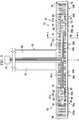
Figure 1 is a perspective view of one possible embodiment of a shaving razor system.Figure 2 is an assembly view of one possible embodiment of a heat delivery element that may be incorporated into the shaving razor system ofFigure 1 .Figure 3 is a top view of one possible embodiment of a heater that may be incorporated into the heat delivery element ofFIG. 2 .Figure 4 is a cross section view of the heater, taken generally along line 4-4 ofFIG. 3 .- Referring to
FIG. 1 , one possible embodiment of the present disclosure is shown illustrating ashaving razor system 10. In certain embodiments, theshaving razor system 10 may include a shavingrazor cartridge 12 mounted to ahandle 14. Theshaving razor cartridge 12 may be fixedly or pivotably mounted to thehandle 14 depending on the overall desired cost and performance. Thehandle 14 may hold a power source, such as one or more batteries (not shown) that supply power to aheat delivery element 16. In certain embodiments, theheat delivery element 16 may comprise a metal, such as aluminum or steel. - The
shaving razor cartridge 12 may be permanently attached or removably mounted from thehandle 14, thus allowing theshaving razor cartridge 12 to be replaced. Theshaving razor cartridge 12 may have ahousing 18 with aguard 20, acap 22 and one ormore blades 24 mounted to thehousing 18 between thecap 22 and theguard 20. Theguard 20 may be toward a front portion of thehousing 18 and thecap 22 may be toward a rear portion of the housing 18 (i.e., theguard 20 is in front of theblades 24 and the cap is behind the blades 24). Theguard 20 and thecap 22 may define a shaving plane that is tangent to theguard 20 and thecap 22. Theguard 20 may be a solid or segmented bar that extends generally parallel to theblades 24. In certain embodiments, theheat delivery element 16 may be positioned in front of theguard 20. - In certain embodiments, the
guard 20 may comprise a skin-engaging member 26 (e.g., a plurality of fins) in front of theblades 24 for stretching the skin during a shaving stroke. In certain embodiments, the skin-engaging member 24 may be insert injection molded or co-injection molded to thehousing 18. However, other known assembly methods may also be used such as adhesives, ultrasonic welding, or mechanical fasteners. The skinengaging member 26 may be molded from a softer material (i.e., lower durometer hardness) than thehousing 18. For example, theskin engaging member 26 may have a Shore A hardness of about 20, 30, or 40 to about 50, 60, or 70. Theskin engaging member 26 may be made from thermoplastic elastomers (TPEs) or rubbers; examples may include, but are not limited to silicones, natural rubber, butyl rubber, nitrile rubber, styrene butadiene rubber, styrene butadiene styrene (SBS) TPEs, styrene ethylene butadiene styrene (SEBS) TPEs (e.g., Kraton), polyester TPEs (e.g., Hytrel), polyamide TPEs (Pebax), polyurethane TPEs, polyolefin based TPEs, and blends of any of these TPEs (e.g., polyester/SEBS blend). In certain embodiments, skinengaging member 26 may comprise Kraiburg HTC 1028/96, HTC 8802/37, HTC 8802/34, or HTC 8802/11 (KRAIBURG TPE GmbH & Co. KG of Waldkraiburg, Germany). A softer material may enhance skin stretching, as well as provide a more pleasant tactile feel against the skin of the user during shaving. A softer material may also aid in masking the less pleasant feel of the harder material of thehousing 18 and/or the fins against the skin of the user during shaving. - In certain embodiments, the
blades 24 may be mounted to thehousing 18 and secured by one ormore clips blades 24 to thehousing 18 including, but not limited to, wire wrapping, cold forming, hot staking, insert molding, ultrasonic welding, and adhesives. Theclips blades 24. Although fiveblades 24 are shown, thehousing 18 may have more or fewer blades depending on the desired performance and cost of the shavingrazor cartridge 12. - The
cap 22 may be a separate molded (e.g., a shaving aid filled reservoir) or extruded component (e.g., an extruded lubrication strip) that is mounted to thehousing 18. In certain embodiments, thecap 22 may be a plastic or metal bar to support the skin and define the shaving plane. Thecap 22 may be molded or extruded from the same material as thehousing 18 or may be molded or extruded from a more lubricious shaving aid composite that has one or more water-leachable shaving aid materials to provide increased comfort during shaving. The shaving aid composite may comprise a water-insoluble polymer and a skin-lubricating water-soluble polymer. Suitable water-insoluble polymers which may be used include, but are not limited to, polyethylene, polypropylene, polystyrene, butadiene-styrene copolymer (e.g., medium and high impact polystyrene), polyacetal, acrylonitrile-butadiene-styrene copolymer, ethylene vinyl acetate copolymer and blends such as polypropylene/polystyrene blend, may have a high impact polystyrene (i.e., Polystyrene-butadiene), such as Mobil 4324 (Mobil Corporation). - Suitable skin lubricating water-soluble polymers may include polyethylene oxide, polyvinyl pyrrolidone, polyacrylamide, hydroxypropyl cellulose, polyvinyl imidazoline, and polyhydroxyethylmethacrylate. Other water-soluble polymers may include the polyethylene oxides generally known as POLYOX (available from Union Carbide Corporation) or ALKOX (available from Meisei Chemical Works, Kyota, Japan). These polyethylene oxides may have molecular weights of about 100,000 to 6 million, for example, about 300,000 to 5 million. The polyethylene oxide may comprise a blend of about 40 to 80% of polyethylene oxide having an average molecular weight of about 5 million (e.g., POLYOX COAGULANT) and about 60 to 20% of polyethylene oxide having an average molecular weight of about 300,000 (e.g., POLYOX WSR-N-750). The polyethylene oxide blend may also contain up to about 10% by weight of a low molecular weight (i.e., MW<10,000) polyethylene glycol such as PEG-100.
- The shaving aid composite may also optionally include an inclusion complex of a skin-soothing agent with a cylcodextrin, low molecular weight water-soluble release enhancing agents such as polyethylene glycol (e.g., 1-10% by weight), water-swellable release enhancing agents such as cross-linked polyacrylics (e.g., 2-7% by weight), colorants, antioxidants, preservatives, microbicidal agents, beard softeners, astringents, depilatories, medicinal agents, conditioning agents, moisturizers, cooling agents, etc.
- The
heat delivery element 16 may include aface plate 30 for delivering heat to the skin's surface during a shaving stroke for an improved shaving experience. In certain embodiments, theface plate 30 may have an outerskin contacting surface 32 comprising a hard coating (that is harder than the material of the face plate 30), such as titanium nitride to improve durability and scratch resistance of theface plate 30. Similarly, if theface plate 30 is manufactured from aluminum, theface plate 30 may go through an anodizing process. The hard coating of the skin contact surface may also be used to change or enhance the color of theskin contacting surface 32 of theface plate 30. Theheat delivery element 16 may be mounted to either the shavingrazor cartridge 12 or to a portion of thehandle 14. As will be described in greater detail below, theheat delivery element 16 may be mounted to thehousing 18 and in communication with the power source (not shown). - Referring to
Fig. 2 , one possible embodiment of theheat delivery element 16 is shown that may be incorporated into the shavingrazor system 10 ofFigure 1 . Theface plate 30 may be as thin as possible, but stable mechanically. For example, theface plate 30 may have a wall thickness of about 100 micrometers to about 200 micrometers. Theface plate 30 may comprise a material having a thermal conductivity of about 10 to 30 W/mK, such as steel. Theface plate 30 being manufactured from a thin piece of steel results in theface plate 30 having a low thermal conductivity thus helping minimize heat loss through aperimeter wall 44 and maximizes heat flow towards theskin contacting surface 32. Although a thinner piece of steel is preferred for the above reasons, theface plate 30 may be constructed from a thicker piece of aluminum having a thermal conductivity ranging from about 160 to 200 W/mK. Theheat delivery element 16 may include a heater (not shown) having abridge 35 that is in electrical contact with micro-controller and a power source (not shown), e.g. a rechargeable battery, positioned within thehandle 14. - The
heat delivery element 16 may include theface plate 30, theheater 34, aheat dispersion layer 36, a compressiblethermal insulation layer 38, and aback cover 40. Theface plate 30 may have a recessedinner surface 42 opposite the skin contacting surface 32 (seeFIG. 1 ) configured to receive theheater 34, theheat dispersion layer 36 and the compressiblethermal insulation layer 38. Theperimeter wall 44 may define theinner surface 42. Theperimeter wall 44 may have one ormore legs perimeter wall 44, transverse to and away from theinner surface 42. For example,Fig. 2 illustrates fourlegs perimeter wall 44. As will be explained in greater detail below, theheater 34 may include heater tracks and electrical tracks, not shown. - The
heat dispersion layer 36 may be positioned on and in direct contact with theinner surface 42 of theface plate 30. Theheat dispersion layer 36 may have alower surface 37 directly contacting theinner surface 42 of theface plate 30 and an upper surface 39 (opposite lower surface 37) directly contacting the heater 34 (for example, the lower dielectric layer shown inFIGS 3 and4 ). Theheat dispersion layer 36 is defined as a layer of material having a high thermal conductivity, and is compressible. For example, theheat dispersion layer 36 may comprise graphite foil. Potential advantages of theheat dispersion layer 36 include improving lateral heat flow (spreading the heat delivery from theheater 34 across theinner surface 42 of theface plate 30, which is transferred to the skin contacting surface 32) resulting in more even heat distribution and minimization of hot and cold spots. Theheat dispersion layer 36 may have an anisotropic coefficient of thermal conductivity in the plane parallel to theface plate 30 of about 200 to about 1700 W/mK (preferably 400 to 700 W/mK) and vertical to theface plate 30 of about 10 to 50 W/mK and preferably 15 to 25 W/mK to facilitate sufficient heat conduction or transfer. In addition, the compressibility of theheat dispersion layer 36 allows theheat dispersion layer 36 adapt to non-uniform surfaces of theinner surface 42 of theface plate 30 and non-uniform surfaces of theheater 34, thus providing better contact and heat transfer. The compressibility of theheat dispersion layer 36 also minimizes stray particulates from pushing into the heater 34 (because theheat dispersion layer 36 may be softer than the heater), thus preventing damage to theheater 34. In certain embodiments, theheat dispersion layer 36 may comprise a graphite foil that is compressed by about 20% to about 50% of its original thickness. For example, theheat dispersion layer 36 may have a compressed thickness of about 50 micrometers to about 300 micrometers more preferably 80 to 200 micrometers. - The
heater 34 may be positioned between two compressible layers. For example, theheater 34 may be positioned between theheat dispersion layer 36 and the compressiblethermal insulation layer 38. The two compressible layers may facilitate clamping theheater 34 in place without damaging theheater 34, thus improving securement and assembly of theheat delivery element 16. The compressiblethermal insulation layer 38 may help direct the heat flow toward theface plate 30 and away from theback cover 40. Accordingly, less heat is wasted and more heat may be able to reach the skin during shaving. The compressiblethermal insulation layer 38 may have low thermal conductivity, for example, less than 0.30 W/mK and preferably less than 0.1 W/mK. In certain embodiments, the compressiblethermal insulation layer 38 may comprise an open cell or closed cellular compressible foam. The compressiblethermal insulation layer 38 may be compressed 20-50% from its original thickness. For example, the compressiblethermal insulation layer 38 may have a compressed thickness of about 400 µm to about 800 µm. - The
back cover 40 may be mounted on top of the compressiblethermal insulation layer 38 and secured to theface plate 30. Accordingly, theheater 34, theheat dispersion layer 36 and the compressiblethermal insulation layer 38 may be pressed together between theface plate 30 and theback cover 40. Theheat dispersion layer 36, theheater 34, and the compressiblethermal insulation layer 38 may fit snugly within theperimeter wall 44. The pressing of the various layers together may result in more efficient heat transfer across the interfaces of the different layers in theheat delivery element 16. In absence of this compression force the thermal transfer across the interfaces is insufficient. Furthermore, the pressing of the layers together may also eliminate secondary assembly processes, such as the use of adhesives between the various layers. The compressiblethermal insulation layer 38 may fit snugly within theperimeter wall 44. - Referring to
FIG. 3 , a top view of theheater 34 is shown. Theheater 34 may have aheater track 48 laid over a lowerdielectric layer 50. One or moreelectrical tracks dielectric layer 50 such that they are all spaced apart from theheater track 48. The one or moreelectrical tracks heater track 48. Theelectrical tracks thermal sensors micro controller 75. The microcontroller may process information from thethermal sensors heater track 48 to regulate temperature accordingly. Thethermal sensor 70 may be thermally connected to asensor pad 68. Similarly, thethermal sensor 76 may be thermally connected to asensor pad 74. Thethermal sensors respective sensor pads heater 34. Athermal sensor pad 84 may be thermally connected to the thermal sensor 86. Similarly, asensor pad 78 may be thermally connected to thethermal sensor 80. Thethermal sensors 80 and 86 andrespective sensor pads heater 34. Thethermal sensors sensor pads thermal sensors 80 and 86 may be positioned laterally between thesensor pads thermal sensors sensor pads heater 34. - One or more of the
thermal sensors circuit board 75 to provide for redundant safety measure if one or more of thethermal sensors thermal sensors heater track 48 by a distance of about 0.05mm to about 0.10mm, which may help prevent direct heating of thethermal sensors sensor pads heater track 48 to provide an accurate temperature reading of the graphite foil layer shown inFIG. 2 . Thesensor pads sensor pads lateral edge dielectric layer 50. For example the sensor pads may be spaced apart from a center line "CL" of the dielectric layer by about 10-30% and from the closestlateral edge dielectric layer 50 by about 10-30%. The spacing and positioning of thesensor pads thermal sensors sensor pads sensor pads thermal sensors - The
heater 34 may include afeeder track bridge 35 and connect the micro-controller to theheater track 48. A width of the feeder tracks 88 and 90 may be more than 5 times a maximum width of theheater track 48 positioned within thefaceplate 30 ofFIG. 2 . The large width of the feeder tracks 88 and 90 supplies energy to theheater track 48 and helps prevent thebridge 35 from becoming too hot to the touch by minimizing the electrical resistance and hence the amount of heat generated. Thebridge 35 may be exposed to the consumer during shaving in order to facilitate pivoting of the shaving razor cartridge 12 (seeFig. 1 ). Accordingly, if thebridge 35 becomes too hot, a consumer may be accidentally burned. Furthermore, thebridge 35 may not be insulated to prevent heat loss. Thus it may be advantageous for thebridge 35 to generate as little heat as possible. - The lower
dielectric layer 50 may comprise polyimide or polytetrafluoroethylene, polyvinylchloride, polyester, or polyethylene terephthalate. Theheater track 48 may include copper tracks having a meander pattern forming a loop along a perimeter of the lowerdielectric layer 50. Theheater track 48 may have varying widths. For example, theheater track 48 may have a width of about 0.05mm to about 0.09mm in afirst area heater 34 and a width of about 0.07mm to about 0.12mm in asecond area heater 34. In certain embodiments, theheater track 48 may have athird area dielectric layer 50 due to theelectrical tracks sensor pads thermal sensors heater track 48 may be symmetrical. For example, theheater track 48 may have the same layout on afirst side 72 of the centerline "CL" as on asecond side 82 of the centerline "CL". - The varying width of the
heater track 48 allows for lower resistance in areas with more space and higher resistance in area of little space to achieve more uniform heat generation. Accordingly, more an equivalent amount of heat may be generated by theheater track 48 in a smaller space, for example in thefirst area second area second area heater 34. Thefirst area 96a may be associated with thethermal sensors 80 and 86 and/orsensor pads end 94 of thedielectric layer 50. Similarly, thefirst area 96b may be associated with thethermal sensors sensor pads dielectric layer 50. For example, thesensor pads thermal sensors 80 and 86 may be positioned between a pair oflengths heater track 48 having a smaller width than a width for alength heater track 48 located in thesecond area 98a. Thesecond area length - The
first area 96b may be associated with thethermal sensors sensor pads end 92 of thedielectric layer 50. Similarly, thefirst area 96b may be associated with thethermal sensors sensor pads dielectric layer 50. For example, thesensor pads thermal sensors lengths heater track 48 having a smaller width than a width for alength heater track 48 located in thesecond area 98b. Thesecond area heater 34 may not have any sensor pads or thermal sensors positioned between the lengths of theheater track 48. For example, in thesecond area 98b, only theelectrical tracks length heater track 48. - A
third area lateral edge dielectric layer 50. For example, thethird area 100a may be positioned between the thermal sensor 86 and thelateral edge 94. Similarly, thethird area 100b may be positioned on the other side of thedielectric layer 50, between thethermal sensor 70 and thelateral edge 92. Thethird area heater track 48 in thethird area heater track 48 because the space is not limited by other electrical components. The layout of thefirst area second area third area - In certain embodiments, the
heater track 48 may have a total resistance of about 1.5 to about 3 Ohms. Theheater track 48 may have a meander pattern forming a loop along a perimeter of thelower polyamide layer 50. For example theheater track 48 may extend around the electrical tracks (i.e., the electrical tracks are positioned within a loop formed by the heater track 48), the thermal sensors and the sensor pads. The meander pattern forming a perimeter or loop and the lower resistance in the area of thethermal sensors sensor pads heater track 48 may have the form of a zigzag; veering to right and left alternately. In certain embodiments, meander pattern of theheater track 48 may have a line or course with abrupt substantially 90 degree turns (e.g., train wave or square wave shape), to provide evenmore heater track 48 within a given area of theheater 34. - Referring to
FIG. 4 , a cross section view of theheater 34 is shown, taken generally along the line 4-4 ofFIG. 3 . Theheater 34 may include the lowerdielectric layer 50, a conductive layer 102 (that comprises theelectrical tracks adhesive layer 104 and anupper dielectric layer 110. Theconductive layer 102 may have a thickness of about 10 µm to about 40 µm (i.e., theelectrical tracks dielectric layer 50 may have a thickness of about 10 µm to about 30 µm. Theupper dielectric layer 110 may have a thickness of about 10 µm to about 30 µm. The conductive layer 102 (comprising theelectrical tracks dielectric layer 50. Since there are spaces between theelectrical tracks heater track 48, theadhesive layer 104 may flow between theelectrical tracks heater track 48 to improve integrity of the fragileconductive layer 102. Theadhesive layer 104 may form a strong bond between theupper dielectric layer 110 and the lowerdielectric layer 50. Theadhesive layers 104 may also cover the conductive layer 102 (i.e., theheater track 48 and electrical tracks) creating a water proof seal. The various materials and thickness that make up theheater 34 allow it to bend under its own weight, thus making theheater 34 more malleable and less susceptible to breaking during handling and assembly. In addition, theheater 34 takes up less space due to its thin profile. In certain embodiments, theupper dielectric layer 110 and/or theadhesive layer 104 may be transparent. For example, theheater track 48 may be visible through theupper dielectric layer 110 and theadhesive layer 104, but may be colored, if desired. - The
heater 34 may be sufficiently thin to provide flexibility and sufficient heat transfer. If the heater 34 (e.g., the lower dielectric layer 50) is too thick, poor heat transfer may result. Theheater 34 may also provide sufficient mechanical stability to allow it to conform during assembly within theface plate 30 ofFIG. 2 . The lower dielectric layer may prevent electrical contact with other layers of theheat delivery element 16, but yet allow sufficient heat transfer. For example, the lower polyimide dielectric layer may prevent the heater track and the electrical tracks from directly contacting the graphite layer or the inner surface of theface plate 30. - The dimensions and values disclosed herein are not to be understood as being strictly limited to the exact numerical values recited. Instead, unless otherwise specified, each such dimension is intended to mean both the recited value and a functionally equivalent range surrounding that value. For example, a dimension disclosed as "40 mm" is intended to mean "about 40 mm".
Claims (15)
- A heat delivery element (16) for a shaving razor comprising:a face plate (30) having a skin contacting surface (32) and an opposing inner surface (42);a heater (34) having a heater track positioned between an upper dielectric layer (110) and a lower dielectric layer (50); anda heat dispersion layer (36) having a lower surface (37) directly contacting the inner surface of the face plate (30) and an upper surface (39) directly contacting the lower dielectric layer of the heater.
- The heat delivery element (16) of claim 1 wherein at least one of the upper dielectric layer (110) and the lower dielectric layer (50) comprises polyimide.
- The heat delivery element (16) according to any one of the preceding claims wherein the heat dispersion layer (36) comprises graphite foil.
- The heat delivery element (16) of claim 3 wherein the heat dispersion layer (36) is compressed by 20% to 50% of an original thickness.
- The heat delivery element (16) according to any one of claims 2-4 wherein the heat dispersion layer (36) has a compressed thickness of 50 to 300 µm.
- The heat delivery element (16) according to any one of the preceding claims further comprising a compressible thermal insulation layer (38) positioned on the dielectric layer (110).
- The heat delivery element (16) of claim 6 wherein the compressible thermal insulation layer (38) has a thermal conductivity less than 0.10 W/mk.
- The heat delivery element (16) of claim 7 wherein the compressible thermal insulation layer (38) comprises a compressible foam.
- The heat delivery element (16) of claim 8 wherein the compressible thermal insulation layer (38) is compressed 30 percent to 70 percent from an original thickness.
- The heat delivery element (16) of claim 8 or 9 wherein the compressible thermal insulation layer (38) has a compressed thickness of 400 to 800 µm.
- The heat delivery element (16) according to any one of the preceding claims further comprising a cover (40) secured to the faceplate 30, wherein the heater (34) and the heat dispersion layer (36) are secured between the face plate (30) and the cover.
- The heat delivery element (16) according to any one of the preceding claims wherein the face plate (30) comprises a recessed inner surface (42) opposite the skin contacting surface (32) configured to receive the thermally conductive layer and the heater (34).
- The heat delivery element (16) according to any one of the preceding claims wherein the face plate (30) has a thickness of 100 to 200 µm.
- The heat delivery element (16) according to any one of the preceding claims wherein the skin contacting surface (32) of the face plate (30) comprises a hard coating.
- The heat delivery element (16) according to any one of the preceding claims wherein the face plate (30) comprises a material having a thermal conductivity of 10 to 30 W/mK.
Priority Applications (11)
| Application Number | Priority Date | Filing Date | Title |
|---|---|---|---|
| EP17152536.3AEP3351358B1 (en) | 2017-01-20 | 2017-01-20 | Heating delivery element for a shaving razor |
| US15/866,596US10766155B2 (en) | 2017-01-20 | 2018-01-10 | Heating delivery element for a shaving razor |
| AU2018210780AAU2018210780B2 (en) | 2017-01-20 | 2018-01-11 | Heating delivery element for a shaving razor |
| KR1020197018977AKR20190088538A (en) | 2017-01-20 | 2018-01-11 | Heating element for shaver |
| PCT/US2018/013236WO2018136284A1 (en) | 2017-01-20 | 2018-01-11 | Heating delivery element for a shaving razor |
| JP2019531050AJP6916286B2 (en) | 2017-01-20 | 2018-01-11 | Heat supply element for shaving razors |
| CA3045049ACA3045049C (en) | 2017-01-20 | 2018-01-11 | Heating delivery element for a shaving razor |
| BR112019014896-5ABR112019014896A2 (en) | 2017-01-20 | 2018-01-11 | HEAT APPLICATION ELEMENT FOR A SHAVING OR DEPILLING APPLIANCE |
| CN202410175636.3ACN117774013A (en) | 2017-01-20 | 2018-01-11 | Heat transfer element for razor |
| CN201880007606.4ACN110198814B (en) | 2017-01-20 | 2018-01-11 | Heat transfer element for razor |
| US16/984,901US11247357B2 (en) | 2017-01-20 | 2020-08-04 | Heating delivery element for a shaving razor |
Applications Claiming Priority (1)
| Application Number | Priority Date | Filing Date | Title |
|---|---|---|---|
| EP17152536.3AEP3351358B1 (en) | 2017-01-20 | 2017-01-20 | Heating delivery element for a shaving razor |
Publications (2)
| Publication Number | Publication Date |
|---|---|
| EP3351358A1 EP3351358A1 (en) | 2018-07-25 |
| EP3351358B1true EP3351358B1 (en) | 2019-11-20 |
Family
ID=57868123
Family Applications (1)
| Application Number | Title | Priority Date | Filing Date |
|---|---|---|---|
| EP17152536.3AActiveEP3351358B1 (en) | 2017-01-20 | 2017-01-20 | Heating delivery element for a shaving razor |
Country Status (9)
| Country | Link |
|---|---|
| US (2) | US10766155B2 (en) |
| EP (1) | EP3351358B1 (en) |
| JP (1) | JP6916286B2 (en) |
| KR (1) | KR20190088538A (en) |
| CN (2) | CN117774013A (en) |
| AU (1) | AU2018210780B2 (en) |
| BR (1) | BR112019014896A2 (en) |
| CA (1) | CA3045049C (en) |
| WO (1) | WO2018136284A1 (en) |
Families Citing this family (19)
| Publication number | Priority date | Publication date | Assignee | Title |
|---|---|---|---|---|
| US10652956B2 (en) | 2016-06-22 | 2020-05-12 | The Gillette Company Llc | Personal consumer product with thermal control circuitry and methods thereof |
| US11052557B2 (en)* | 2016-11-04 | 2021-07-06 | Heated Blades Holding Company, Llc | Heating blades of razor using RF energy |
| EP3351358B1 (en) | 2017-01-20 | 2019-11-20 | The Gillette Company LLC | Heating delivery element for a shaving razor |
| WO2019191163A1 (en) | 2018-03-30 | 2019-10-03 | The Gillette Company Llc | Razor handle with a pivoting portion |
| BR112020020132A2 (en) | 2018-03-30 | 2021-01-05 | The Gillette Company Llc | HANDLE OF SHAVING OR DEVILING APPLIANCE WITH MOBILE LIMBS |
| EP3546156B1 (en) | 2018-03-30 | 2021-03-10 | The Gillette Company LLC | Razor handle with a pivoting portion |
| EP3774227A1 (en) | 2018-03-30 | 2021-02-17 | The Gillette Company LLC | Razor handle with movable members |
| US11607820B2 (en) | 2018-03-30 | 2023-03-21 | The Gillette Company Llc | Razor handle with movable members |
| USD874061S1 (en) | 2018-03-30 | 2020-01-28 | The Gillette Company Llc | Shaving razor cartridge |
| WO2019190962A1 (en) | 2018-03-30 | 2019-10-03 | The Gillette Company Llc | Razor handle with a pivoting portion |
| US10773408B2 (en) | 2018-03-30 | 2020-09-15 | The Gillette Company Llc | Shaving razor cartridge |
| CN111801205B (en) | 2018-03-30 | 2022-08-23 | 吉列有限责任公司 | Razor handle with pivoting portion |
| EP3774215B1 (en) | 2018-03-30 | 2024-03-13 | The Gillette Company LLC | Razor handle with a pivoting portion |
| CN111819048A (en) | 2018-03-30 | 2020-10-23 | 吉列有限责任公司 | Razor handle with pivoting portion |
| JP2021515672A (en) | 2018-03-30 | 2021-06-24 | ザ ジレット カンパニー リミテッド ライアビリティ カンパニーThe Gillette Company Llc | Razor system for shaving |
| CA3092879A1 (en) | 2018-03-30 | 2019-10-03 | The Gillette Company Llc | Razor handle with movable members |
| JP7104168B2 (en) | 2018-03-30 | 2022-07-20 | ザ ジレット カンパニー リミテッド ライアビリティ カンパニー | Razor handle with pivot part |
| KR102202274B1 (en)* | 2019-05-14 | 2021-01-13 | 주식회사 도루코 | Razor Cartridge and Razor Assembly Using The Same |
| GB2587441B (en)* | 2019-09-24 | 2023-10-11 | Heated Blades Holding Company Llc | Heating blades of razor using RF energy |
Family Cites Families (277)
| Publication number | Priority date | Publication date | Assignee | Title |
|---|---|---|---|---|
| FR520234A (en) | 1919-07-19 | 1921-06-22 | Axel Edward Astrand | Improvements to razors and similar utensils |
| US1505578A (en) | 1923-03-26 | 1924-08-19 | Barra Charles | Razor |
| US1552026A (en) | 1923-07-12 | 1925-09-01 | Barra Charles | Safety razor |
| US1821574A (en) | 1928-05-16 | 1931-09-01 | Peters Peter Nicholas | Razor |
| FR749861A (en) | 1932-02-01 | 1933-08-01 | Aeg | Heated razor |
| US2018147A (en) | 1932-02-01 | 1935-10-22 | Pirwitz Emil | Safety razor |
| DE575523C (en) | 1932-02-01 | 1933-04-28 | Emil Pirwitz | Heatable razor |
| US1892836A (en) | 1932-04-29 | 1933-01-03 | George R Harvey | Combination razor and shaving brush |
| US2063808A (en) | 1935-08-16 | 1936-12-08 | Thomas J Henderson | Electrically heated safety razor |
| US2225257A (en) | 1936-07-21 | 1940-12-17 | Fernan O Conill | Razor |
| US2164581A (en) | 1937-12-31 | 1939-07-04 | George R Ewald | Thermoelectric rotary razor |
| FR840502A (en) | 1938-02-10 | 1939-04-27 | Advanced safety razor with recordable heated blade | |
| US2231219A (en) | 1938-10-31 | 1941-02-11 | Peterson Payson | Razor |
| GB541723A (en) | 1940-06-06 | 1941-12-09 | Hans Otto Hoffmann | Improvements in shaving apparatus |
| US2324148A (en) | 1942-01-30 | 1943-07-13 | Moses M Gravin | Electrically heated safety razor |
| US2327192A (en) | 1943-05-26 | 1943-08-17 | Arthur E Keene | Soap-containing safety razor |
| US2414482A (en) | 1943-10-18 | 1947-01-21 | Norman Kelso | Electric soldering iron |
| US2622319A (en) | 1948-12-14 | 1952-12-23 | Hunt James Russell | Electric heat shaver |
| FR985030A (en) | 1949-02-16 | 1951-07-13 | Razor enhancements | |
| US2536844A (en) | 1949-08-25 | 1951-01-02 | Frederick Carlton | Thermal scraper |
| US2714651A (en) | 1951-05-25 | 1955-08-02 | Wotton Charles Sydney Richard | Electrically heated soldering irons |
| NL6406028A (en) | 1964-05-29 | 1965-11-30 | ||
| US3325627A (en) | 1964-09-30 | 1967-06-13 | Adler | Electrically heated mixing spatula |
| US3364568A (en) | 1965-12-09 | 1968-01-23 | Lowy Nathaniel | Shaver having selectively operable heating and cooling means |
| US3454745A (en) | 1967-09-25 | 1969-07-08 | Knapp Monarch | Heater for shaving lather containers |
| US3591923A (en) | 1968-07-31 | 1971-07-13 | Turner & Seymour Mfg Co The | Handle attachment |
| US3611568A (en) | 1969-08-20 | 1971-10-12 | Gillette Co | Vibratory safety razor |
| US3648368A (en) | 1970-03-23 | 1972-03-14 | Gillette Co | Safety razor |
| US3795979A (en) | 1972-04-27 | 1974-03-12 | Gillette Co | Handle |
| US3876858A (en) | 1973-02-09 | 1975-04-08 | French Co R T | Shrink-film hole-burning device |
| US3896364A (en) | 1973-08-15 | 1975-07-22 | Richard A Reister | Electric razor adapter |
| US3934115A (en) | 1973-09-25 | 1976-01-20 | Peterson Gerald H | Method and apparatus for electric singe cutting |
| NO139756C (en) | 1976-12-21 | 1979-05-02 | Norsk Treteknisk Inst | PROCEDURE AND DEVICE FOR AA CONTROLLING TEMPERATURE TENSIONS IN A SAWING MACHINE SAW SHEET |
| US4077119A (en) | 1977-02-16 | 1978-03-07 | Jose Manuel Sellera | Shaving device |
| JPS5753552Y2 (en) | 1977-06-30 | 1982-11-19 | ||
| JPS5610243Y2 (en) | 1977-09-05 | 1981-03-07 | ||
| DE2801845A1 (en) | 1978-01-13 | 1979-07-19 | Joerg Munder | Wet razor with replaceable blade - has heating element fitted in region of blade support |
| JPS5566396U (en) | 1978-10-31 | 1980-05-07 | ||
| US4266340A (en) | 1979-06-11 | 1981-05-12 | Warner-Lambert Company | Razor handle for mounting pivotable razor blade cartridges |
| EP0020816A1 (en) | 1979-06-19 | 1981-01-07 | The Gillette Company | Shaving razor assembly |
| JPS56128188A (en) | 1980-03-10 | 1981-10-07 | Hideo Ishii | Razor with heating tool |
| US4377034A (en) | 1980-11-10 | 1983-03-22 | Druash Alex F | Safety razor kit |
| US4403414A (en) | 1981-04-09 | 1983-09-13 | Warner-Lambert Company | Socket device for a pivotal razor |
| US4514904A (en) | 1983-09-21 | 1985-05-07 | The Gillette Company | Razor handle |
| US4716652A (en) | 1983-10-05 | 1988-01-05 | John Cataudella | Disposable shaver |
| US4598192A (en) | 1984-03-02 | 1986-07-01 | Garrett John E | Electrically heated handle for fishing rods |
| US4587968A (en) | 1984-03-19 | 1986-05-13 | Price David R | Electric emasculator and method for castrating |
| JPS60194333U (en) | 1984-06-05 | 1985-12-24 | キヤノン株式会社 | temperature control device |
| GB8506831D0 (en) | 1985-03-15 | 1985-04-17 | Wilkinson Sword Ltd | Razor handle |
| US4809432A (en) | 1986-11-24 | 1989-03-07 | Shaverd Corp. | Disposable razor and emollient dispensing device |
| US4797998A (en) | 1986-12-08 | 1989-01-17 | Warner-Lambert Company | Lockable pivotable razor |
| DE3866370D1 (en) | 1987-01-30 | 1992-01-09 | Eurafrica | SAFETY SHAVER. |
| US4879811A (en) | 1987-10-01 | 1989-11-14 | Cooney Daniel J | Safety razor |
| US4864735A (en) | 1988-02-18 | 1989-09-12 | Chung Chang L | Multi-purpose presence grooming implement |
| US4918818A (en) | 1988-09-22 | 1990-04-24 | Hsieh Yin Fei | Multi-purpose massage shaver |
| US5191712A (en) | 1988-10-28 | 1993-03-09 | The Gillette Company | Safety razors and guards |
| DE8903182U1 (en) | 1989-03-15 | 1989-05-03 | Wilkinson Sword GmbH, 5650 Solingen | Double-head shaver |
| JP2714462B2 (en) | 1989-08-19 | 1998-02-16 | 松下電工株式会社 | Vibrating razor |
| US5010905A (en) | 1989-10-20 | 1991-04-30 | Snyder Marilyn J | Water-vapor hair treatment apparatus |
| US5098414A (en) | 1990-01-17 | 1992-03-24 | Walker Cedric T M | Steaming device for cosmetic skin treatment |
| US5016352A (en) | 1990-03-22 | 1991-05-21 | The Gillette Company | Single button razor |
| US5157834A (en) | 1990-04-10 | 1992-10-27 | Warner-Lambert Company | Razor mechanism with slidable cartridge support |
| US5044077A (en) | 1990-04-10 | 1991-09-03 | Warner-Lambert Company | Razor mechanism |
| IT1246250B (en) | 1990-07-10 | 1994-11-17 | Giovanni Caron | HIGHLY HEATED, THERMALLY CONTROLLED CUTTING SCISSORS, IN PARTICULAR TO THE EFFECTS OF ASEPTICITY AND TO SELF-CAUSE THE HAIR DURING THE CUT AS WELL AS THE SYSTEM FOR THEIR MANAGEMENT |
| US5113585A (en) | 1990-09-28 | 1992-05-19 | The Gillette Company | Shaving system |
| US5299354A (en) | 1990-10-11 | 1994-04-05 | The Gillette Company | Oscillating shaver |
| JP2777747B2 (en) | 1990-11-26 | 1998-07-23 | 東亞合成株式会社 | Multilayer printed circuit board with built-in printed resistor having electromagnetic wave shielding layer |
| CA2101163A1 (en) | 1991-01-24 | 1992-07-25 | Richard A. Iderosa | Thermally assisted shaving system |
| US5065515A (en) | 1991-01-24 | 1991-11-19 | Warner-Lambert Company | Thermally assisted shaving system |
| US5394777A (en) | 1991-09-26 | 1995-03-07 | Warner-Lambert Company | Thermally enhanced shaving system |
| US5191172A (en) | 1991-11-07 | 1993-03-02 | Garganese Richard S | Cable terminal protector |
| US5121541A (en) | 1991-11-12 | 1992-06-16 | Patrakis Strati G | Electric razor with built-in mister |
| US5333382A (en) | 1992-03-02 | 1994-08-02 | Ligaya Corporation | Brow shaver |
| GB9208098D0 (en) | 1992-04-13 | 1992-05-27 | Gillette Co | Razor with movable cartridge |
| EP0654983A4 (en) | 1992-08-17 | 1995-12-13 | Mehl Thomas L | Hand-held, portable steam razor. |
| JP2839418B2 (en) | 1992-10-29 | 1998-12-16 | 京セラ株式会社 | Temperature sensor |
| JPH06216532A (en) | 1993-01-18 | 1994-08-05 | Toshiba Corp | Multilayer board with built-in element |
| FR2703290A1 (en) | 1993-04-02 | 1994-10-07 | Mendola Claude | Heating device improving the comfort of mechanical shaving of the epidermis |
| US5337478A (en) | 1993-05-03 | 1994-08-16 | Zaki Cohen | Automatic shaving apparatus |
| AU6698694A (en) | 1993-05-07 | 1994-12-12 | Warner-Lambert Company | Thermally assisted shaving system |
| IL105759A (en) | 1993-05-20 | 1994-12-29 | Aurora Dawn Ltd | Twin blade spray razor |
| US5347717A (en) | 1993-11-05 | 1994-09-20 | Ts Ai Tse Jen | Chuck assembly for a disposable razor |
| FR2716402B1 (en) | 1994-02-23 | 1996-03-29 | Garets Christian Des | Improvements made to a shaving device. |
| US5454164A (en) | 1994-03-17 | 1995-10-03 | The Gillette Company | Wet shaving system with a lubricating device |
| JPH08202459A (en) | 1995-01-24 | 1996-08-09 | Chino Corp | Control device |
| US5933960A (en) | 1995-03-23 | 1999-08-10 | Avidor; Joseph | Shaving apparatus and method of shaving |
| DE29506308U1 (en) | 1995-04-12 | 1995-07-06 | THERAcut - Hair - Technik GmbH, 78194 Immendingen | Device for heating the blades of scissors, knives and the like. |
| US5600887A (en) | 1995-05-26 | 1997-02-11 | Olson; Brad | Flexible easy-rinsing razor |
| US5780819A (en) | 1995-07-07 | 1998-07-14 | Fabrikant; Marvin | Heater for shaving cream containers with dome-shaped support and heating surface |
| US5786573A (en) | 1995-07-07 | 1998-07-28 | Fabrikant; Marvin | Heater for shaving cream containers enabling vertical adjustment of the heater relative to the container |
| WO1997008804A1 (en) | 1995-08-22 | 1997-03-06 | Philips Electronics N.V. | Combination of an electrical appliance and an associated stand |
| US5953825A (en) | 1996-01-16 | 1999-09-21 | The Gillette Company | Safety razors |
| US5787586A (en) | 1996-04-10 | 1998-08-04 | The Gillette Company | Shaving system and method |
| US5794342A (en) | 1996-08-09 | 1998-08-18 | Davey; Melville G. | Oscillating blade razor |
| JP3066524B2 (en) | 1996-08-23 | 2000-07-17 | 株式会社デベロ | Remote control method and remote control device for hot water supply temperature |
| JPH10165521A (en) | 1996-12-06 | 1998-06-23 | Kobayashi Sangyo Kk | Therapeutic and beauty heaters |
| JPH10207288A (en) | 1997-01-23 | 1998-08-07 | Canon Inc | Heater, fixing device, and image forming device |
| US5782346A (en) | 1997-02-19 | 1998-07-21 | The Gillette Company | Tray for a wet shaving razor |
| IT1298729B1 (en) | 1997-03-13 | 2000-02-02 | Digital Appliance Controls Inc | SYSTEM OF CONTROL OF APPLIANCES IN GENERAL WITH STOP PROCESSORS IN THE EVENT OF FAILURE |
| US5794343A (en) | 1997-05-12 | 1998-08-18 | The Gillette Company | Razor blade assembly |
| US6421918B1 (en) | 1997-06-16 | 2002-07-23 | Warner-Lambert Company | High frequency wet/dry shaving system |
| CA2235115A1 (en) | 1997-06-16 | 1998-12-16 | David C. Coffin | Razor providing pivoting and swivelling razor head support |
| JP3986130B2 (en) | 1997-08-25 | 2007-10-03 | ヤマハマリン株式会社 | Power supply circuit for outboard motor lifting equipment |
| US6061912A (en) | 1997-10-30 | 2000-05-16 | Gazaway; Eileen L. | Instrument for cutting multi-strand plastic fiber materials |
| US6460251B1 (en) | 1998-03-25 | 2002-10-08 | Pfizer Inc. | Razor system with worn blade indicator |
| US6161287A (en) | 1998-04-24 | 2000-12-19 | The Gillette Company | Razor blade system |
| US6499218B2 (en) | 1998-12-28 | 2002-12-31 | Manual Antonio Rocha | Four sided dual blade shaver |
| GB9903415D0 (en) | 1999-02-15 | 1999-04-07 | Gillette Co | Safety razors |
| US6158125A (en) | 1999-02-22 | 2000-12-12 | Dolev; Moshe | Cutter assemblies for electric shavers |
| US6817101B1 (en) | 1999-04-28 | 2004-11-16 | Display Matrix Corporation | Hot blade razor |
| US20030101589A1 (en) | 1999-05-17 | 2003-06-05 | Barish Benjamin J. | Attachments for electrical shaver and auxiliary cleaning device useful for electrical shaver |
| US6301792B1 (en) | 2000-01-25 | 2001-10-16 | Roger D. Speer | Rechargeable shaving apparatus for vehicle |
| TWM245035U (en) | 2000-02-23 | 2004-10-01 | Sanyo Electric Co | Electric shaver |
| CN1227099C (en) | 2000-06-21 | 2005-11-16 | 皇家菲利浦电子有限公司 | Hair removing apparatus comprising plate-shaped carriers which are positioned and movable with respect to each other |
| JP3776297B2 (en) | 2000-07-12 | 2006-05-17 | 株式会社山武 | Control system |
| JP2002066172A (en) | 2000-08-28 | 2002-03-05 | Marumiya:Kk | Shaver |
| US6481104B1 (en) | 2000-09-22 | 2002-11-19 | Sharper Image Corporation | Vibrating shaving systems |
| EP1346607B1 (en) | 2000-11-29 | 2012-07-25 | Thermoceramix, LLC | Resistive heaters and uses thereof |
| WO2002065871A1 (en) | 2001-02-23 | 2002-08-29 | Koninklijke Philips Electronics N.V. | Hair removing device comprising a heating member |
| US20030046816A1 (en)* | 2001-03-01 | 2003-03-13 | Steve Kanzer | Shaving razor having a heat sink razor head |
| ES2292720T3 (en) | 2001-03-09 | 2008-03-16 | Datec Coating Corporation | RESISTIVE COATING AND DRIVER DERIVED FROM SOL-GEL. |
| US7170034B2 (en) | 2002-02-05 | 2007-01-30 | Radiancy Inc. | Pulsed electric shaver |
| JP4227893B2 (en) | 2001-07-23 | 2009-02-18 | レイディアンシー インク. | Pulse electric shaver |
| US6868610B2 (en) | 2001-11-15 | 2005-03-22 | The Gillette Company | Shaving razors and razor cartridges |
| US7111400B2 (en) | 2002-01-30 | 2006-09-26 | Eveready Battery Company, Inc. | Razor having thermo-electric shaving aid ejection system and method of ejecting shaving aid |
| US7038333B2 (en) | 2002-02-15 | 2006-05-02 | The Gillette Company | Hybrid power supply |
| US6836966B2 (en)* | 2002-06-06 | 2005-01-04 | SLE Limited Partnership | Heated razor and electric shaver |
| US7471062B2 (en) | 2002-06-12 | 2008-12-30 | Koninklijke Philips Electronics N.V. | Wireless battery charging |
| US6763590B2 (en) | 2002-10-21 | 2004-07-20 | Eveready Battery Company, Inc. | Razor assembly having a clutch controlled shaving aid delivery system |
| US7645963B2 (en) | 2002-11-22 | 2010-01-12 | Koninklijke Philips Electronics N.V. | Sol-gel based heating element |
| JP3898118B2 (en) | 2002-12-05 | 2007-03-28 | シンワ測定株式会社 | Manufacturing method of sheet heating device having temperature detection function |
| GB2399045B (en) | 2003-02-19 | 2005-11-16 | Gillette Co | Safety razors |
| GB2398534B (en) | 2003-02-19 | 2005-11-16 | Gillette Co | Safety razors |
| US7654003B2 (en) | 2003-02-19 | 2010-02-02 | The Gillette Company | Safety razors with charge indicator and power switch |
| GB0303872D0 (en) | 2003-02-19 | 2003-03-26 | Gillette Co | Hand held appliances |
| JP2006514566A (en) | 2003-03-13 | 2006-05-11 | レイディアンシー インク. | Heat shaving electric shaver with removable head |
| GB2408010B (en) | 2003-11-17 | 2007-03-28 | Knowledge & Merchandising Inc | Shaving product |
| DE10355154A1 (en) | 2003-11-26 | 2005-06-30 | Wahl Gmbh | Cutting set for electric hair clippers |
| BR0318654B1 (en) | 2003-12-12 | 2014-09-23 | Bic Violex Sa | IMPROVED PROCESS FOR MANUFACTURING A WET SHAVING SYSTEM WITH A PROTECTION BAR |
| US6910274B1 (en) | 2003-12-16 | 2005-06-28 | Eveready Battery Company, Inc. | Shaving apparatus |
| US7137203B2 (en) | 2003-12-30 | 2006-11-21 | Eveready Battery Company, Inc. | Shaving apparatus |
| US20050189338A1 (en) | 2004-02-26 | 2005-09-01 | Sukeforth Carl J. | Heat apparatus for extending the life of blade cutting edges |
| US7197825B2 (en) | 2004-03-11 | 2007-04-03 | The Gillette Company | Razors and shaving cartridges with guard |
| US7690122B2 (en) | 2004-03-11 | 2010-04-06 | The Gillette Company | Shaving razor with button |
| US7168173B2 (en) | 2004-03-11 | 2007-01-30 | The Gillette Company | Shaving system |
| WO2005090016A1 (en) | 2004-03-15 | 2005-09-29 | Bic-Violex Sa | Razor having two silideable shaving heads |
| JP4024773B2 (en) | 2004-03-30 | 2007-12-19 | シャープ株式会社 | WIRING BOARD, SEMICONDUCTOR DEVICE, ITS MANUFACTURING METHOD, AND SEMICONDUCTOR MODULE DEVICE |
| US8615886B1 (en) | 2004-05-06 | 2013-12-31 | Winthrop D. Childers | Shaving system with energy imparting device |
| US20050268472A1 (en) | 2004-06-07 | 2005-12-08 | Bourilkov Jordan T | Shaving systems |
| GB2417007B (en) | 2004-08-13 | 2009-03-11 | Gillette Co | Razors |
| US20060070242A1 (en)* | 2004-10-01 | 2006-04-06 | Szczepanowski Andrew A | Shaving razors and razor cartridges |
| US8033023B2 (en) | 2004-10-20 | 2011-10-11 | The Gillette Company | Shaving razors and cartridges |
| US6946624B1 (en) | 2004-12-03 | 2005-09-20 | Tomassetti Louis D | Heated tray for razor |
| US20060117568A1 (en) | 2004-12-03 | 2006-06-08 | Tomassetti Louis D | Heated razor cartridge |
| US7681320B2 (en) | 2004-12-15 | 2010-03-23 | The Gillette Company | Shaving razors and razor cartridges |
| US20070050995A1 (en) | 2005-09-06 | 2007-03-08 | Fred Schnak | Razors |
| EP1937444B1 (en) | 2005-09-14 | 2013-04-17 | Eveready Battery Company, Inc. | Blade mounting members for a razor cartridge |
| US7743506B2 (en) | 2005-10-11 | 2010-06-29 | The Gillette Company | Heated shaving razors |
| US7520408B1 (en) | 2005-10-13 | 2009-04-21 | Anthony Smith | Dripless hot glue gun |
| KR100769564B1 (en) | 2006-02-28 | 2007-10-23 | 조중범 | Razors with heating means |
| US20070271714A1 (en) | 2006-03-17 | 2007-11-29 | Light Dimensions, Inc. | Light-based enhancing apparatuses and methods of use |
| US7788810B2 (en) | 2006-07-24 | 2010-09-07 | Eveready Battery Company, Inc. | Shaving system having an umbilical |
| JP4749278B2 (en) | 2006-08-30 | 2011-08-17 | 株式会社不二工機 | Connector, conductive connection structure and conductive connection method |
| JP2008063187A (en) | 2006-09-07 | 2008-03-21 | Ngk Spark Plug Co Ltd | Silicon nitride sintered compact, ceramic substrate for heat dissipation and insulation, circuit board for heat dissipation and insulation and module for heat dissipation and insulation |
| FR2906180B1 (en) | 2006-09-21 | 2008-12-05 | Bic Soc | DEVICE AND METHOD FOR BLADE SHAVING |
| US7770294B2 (en) | 2007-08-30 | 2010-08-10 | The Gillette Company | Razor with blade unit biasing member |
| GB0716941D0 (en) | 2007-08-31 | 2007-10-10 | Knowledge & Merchandising Inc | Razor handle |
| US8122606B2 (en) | 2007-09-17 | 2012-02-28 | The Gillette Company | Cartridge life indicator |
| US8230600B2 (en) | 2007-09-17 | 2012-07-31 | The Gillette Company | Cartridge detachment sensor |
| US20090119923A1 (en) | 2007-09-17 | 2009-05-14 | Robert Anthony Hart | Sensor For A Razor |
| TW200930190A (en) | 2007-10-03 | 2009-07-01 | Fujikura Ltd | Module, curcuit board and method of manufacturing module |
| US9071073B2 (en) | 2007-10-04 | 2015-06-30 | The Gillette Company | Household device continuous battery charger utilizing a constant voltage regulator |
| MX2010007860A (en) | 2008-01-17 | 2010-11-30 | Syneron Medical Ltd | A hair removal apparatus for personal use and the method of using same. |
| US20090255123A1 (en) | 2008-04-15 | 2009-10-15 | Tomassetti Louis D | Razor with blade heating system |
| US9149945B2 (en)* | 2008-04-15 | 2015-10-06 | L.P.I. Consumer Products, Inc. | Razor with blade heating system |
| BRPI0913305A2 (en) | 2008-05-23 | 2019-09-24 | The Gilette Company | shaving or shaving device comprising a three-dimensional microstructured abrasive material |
| WO2009154921A2 (en) | 2008-06-19 | 2009-12-23 | The Gillette Company | Safety razor having pivotable blade unit |
| CN101306537A (en) | 2008-06-26 | 2008-11-19 | 孙晓松 | Method and products thereof capable of heating blade on shaver |
| DE102008032389A1 (en) | 2008-07-09 | 2010-01-14 | Richard Seidenbusch | Disposable electric razor, has hand part comprising energy source and pole contact for head part, superior double track skin contact strip forming bridge field and pole, and blades forming antipole |
| CN201253863Y (en) | 2008-07-17 | 2009-06-10 | 孙晓松 | Electroheat shaver |
| US20100031510A1 (en) | 2008-08-06 | 2010-02-11 | Matthias Gester | Heated shaving razor |
| US8205344B2 (en) | 2008-08-20 | 2012-06-26 | The Gillette Company | Safety razor having pivotable blade unit |
| JP5320908B2 (en) | 2008-08-29 | 2013-10-23 | 富士通株式会社 | Temperature control device for temperature chamber |
| WO2010031435A1 (en) | 2008-09-18 | 2010-03-25 | Bic-Violex Sa | Razor with a retractable shaving cartridge and razor handle for such a handle. |
| WO2010042878A1 (en) | 2008-10-10 | 2010-04-15 | Avon Products, Inc. | Ergonomic mascara applicator |
| US20100122464A1 (en) | 2008-11-14 | 2010-05-20 | Thilivhali Tshikovhi Ndou | Razor Cartridge with Skin Engaging Member |
| WO2010068070A2 (en) | 2008-12-11 | 2010-06-17 | Cho Won-Sang | Two-sided razor |
| EP2218559B1 (en) | 2009-02-13 | 2012-08-15 | Trisa Holding AG | Body care device |
| DE202009003889U1 (en) | 2009-03-19 | 2009-05-28 | Rational Ag | Cooking appliance |
| WO2010108101A2 (en) | 2009-03-19 | 2010-09-23 | Weiss Controls, Inc. | Method and system for controlling a heating element with temperature sensitive conductive layer |
| KR20100108753A (en) | 2009-03-30 | 2010-10-08 | 씨앤디아이(주) | Shaver having the heating function |
| US8611976B2 (en) | 2009-05-14 | 2013-12-17 | Covidien Lp | Breathable physiological sensor |
| WO2010136943A1 (en) | 2009-05-28 | 2010-12-02 | Koninklijke Philips Electronics N.V. | Pivoting arrangement |
| PL2266727T3 (en) | 2009-06-22 | 2016-04-29 | Gillette Co | A method of forming a functional razor cartridge |
| WO2011004913A1 (en) | 2009-07-09 | 2011-01-13 | 新日本製鐵株式会社 | Steel wire for high-strength spring |
| US8209868B2 (en) | 2009-07-27 | 2012-07-03 | The Gillette Company | Device with an illuminated button assembly |
| WO2011012172A1 (en) | 2009-07-31 | 2011-02-03 | Bic-Violex Sa | Wet shaver |
| US20110067245A1 (en) | 2009-09-21 | 2011-03-24 | Kelly Daniel Bridges | Shaving Razors and Cartridges |
| US20110126413A1 (en) | 2009-12-02 | 2011-06-02 | Andrew Anthony Szczepanowski | Razor cartridge components with indicia |
| EP2506773B1 (en) | 2009-12-06 | 2018-08-15 | Syneron Medical Ltd. | Apparatus for personal skin treatment |
| US20110146080A1 (en) | 2009-12-23 | 2011-06-23 | Pauw Jacobus Cornelis | Razor |
| EP2338652B1 (en) | 2009-12-23 | 2015-04-22 | Jacobus Cornelis Pauw | A razor |
| KR20110077082A (en) | 2009-12-30 | 2011-07-07 | 주식회사 도루코 | Shaver containing thermostatic capsule |
| US8516706B2 (en)* | 2010-01-08 | 2013-08-27 | Syneron Medical Ltd | Skin-heating shaving apparatus and method |
| EP2366507B1 (en) | 2010-03-15 | 2015-05-13 | The Gillette Company | Razor cartridge |
| RU2012139451A (en) | 2010-03-16 | 2014-04-27 | Баркей Гмбх Унд Ко. Кг | DEVICE FOR HEATING MOVING FLUIDS, AND ALSO WAY OF ITS MANUFACTURE |
| PL2558252T3 (en) | 2010-04-15 | 2015-12-31 | Gillette Co | Fluid dispensing hair removal device |
| US8481898B2 (en) | 2010-06-04 | 2013-07-09 | Robert Parker | Self regulating electric heaters |
| US8720072B2 (en) | 2010-08-11 | 2014-05-13 | Thomas J. Bucco | Razor with three-axis multi-position capability |
| US8745883B2 (en) | 2010-09-29 | 2014-06-10 | The Gillette Company | Razor handle with a rotatable portion |
| US8769825B2 (en) | 2010-10-20 | 2014-07-08 | The Gillette Company | Shaving razor including a biasing member producing a progressively increasing cartridge return torque and handle geometry enhancing control during shaving |
| US8650763B2 (en) | 2010-10-20 | 2014-02-18 | The Gillette Company | Shaving razor providing enhanced control during shaving |
| CN102452089B (en) | 2010-10-28 | 2015-01-14 | 吉列公司 | Hair removing blade holder with slender groove |
| CN102452085B (en) | 2010-10-28 | 2016-01-27 | 吉列公司 | For the pump of the hair removal device of dispense liquid |
| CN102452092B (en) | 2010-10-28 | 2015-04-01 | 吉列公司 | Hair removing device for dispensing liquid |
| US20120167392A1 (en) | 2010-12-30 | 2012-07-05 | Stmicroelectronics Pte. Ltd. | Razor with chemical and biological sensor |
| DE102011011366B4 (en) | 2011-02-16 | 2012-08-23 | Borgwarner Beru Systems Gmbh | Electric heater and assembly for this |
| CN202085323U (en)* | 2011-03-01 | 2011-12-21 | 杜玉凤 | Energy-saving heating device |
| US20120227554A1 (en) | 2011-03-07 | 2012-09-13 | Jack Beech | Grooming device with leveling indicators |
| PL2508309T3 (en) | 2011-04-05 | 2017-02-28 | The Gillette Company | Razor handle with a rotatable portion |
| US20120255942A1 (en) | 2011-04-06 | 2012-10-11 | Hankscraft Inc. | Traffic Light Heater |
| US20120279075A1 (en) | 2011-05-02 | 2012-11-08 | Amsel Klaus Guenter | Improved battery housing for battery-powered device |
| US8732966B2 (en) | 2011-05-02 | 2014-05-27 | Wahl Clipper Corporation | Snap-on grip attachment for hair clipper |
| US8713801B2 (en) | 2011-05-18 | 2014-05-06 | L.P.I. Consumer Products, Inc. | Razor with blade heating system |
| US9604375B2 (en)* | 2011-05-18 | 2017-03-28 | Heated Blades Holding Company, Llc | Razor with blade heating system |
| JP5860707B2 (en) | 2011-05-18 | 2016-02-16 | 株式会社貝印刃物開発センター | Swing razor |
| US20120311865A1 (en) | 2011-06-08 | 2012-12-13 | Zafirro, Llc | Mineral blade and razor for use with same |
| JP6022560B2 (en) | 2011-06-22 | 2016-11-09 | ラディアンシー インク. | Hair loss and hair growth inhibiting device |
| US20130081290A1 (en) | 2011-10-03 | 2013-04-04 | Matthew Frank Murgida | Razor handle with a rotatable portion |
| JP5827535B2 (en) | 2011-10-12 | 2015-12-02 | サンデンホールディングス株式会社 | In-vehicle heater control system |
| EP2591895B1 (en) | 2011-11-10 | 2019-02-27 | The Gillette Company LLC | Razor cartridge with lubrication and moisturizing strips |
| CA2856632C (en) | 2011-12-09 | 2017-08-15 | The Gillette Company | Replaceable fluid dispensing cartridge |
| US8887369B2 (en) | 2011-12-09 | 2014-11-18 | The Gillette Company | Personal-care appliance and method of assembly |
| US20150032128A1 (en) | 2012-01-26 | 2015-01-29 | Slender Medical Ltd. | Ultrasonic skin treatment device with hair removal capability |
| US9084891B2 (en) | 2012-02-06 | 2015-07-21 | David Aberizk | Pilomotor effect stimulating device and method |
| US8938885B2 (en) | 2012-05-01 | 2015-01-27 | The Gillette Company | Razor handle with a rotatable portion |
| US8969730B2 (en) | 2012-08-16 | 2015-03-03 | Apple Inc. | Printed circuit solder connections |
| KR101457766B1 (en) | 2012-09-26 | 2014-12-09 | 주식회사 도루코 | Handle assembly and the razor using the same |
| KR101499293B1 (en) | 2012-09-28 | 2015-03-06 | 주식회사 도루코 | Heating shaving cartridge |
| US9623575B2 (en) | 2012-12-18 | 2017-04-18 | Shavelogic, Inc. | Shaving systems |
| EP2934826B1 (en) | 2012-12-21 | 2017-12-13 | BIC-Violex S.A. | Shaver |
| CN103208780B (en) | 2013-04-12 | 2016-01-27 | 苏州欧泰克电子科技有限公司 | Direct current motor control circuit with thermal protection function |
| CN103235614B (en) | 2013-05-13 | 2015-04-01 | 上海富士施乐有限公司 | Safety control circuit of thermal fixer |
| EP3010685B1 (en) | 2013-06-19 | 2021-09-22 | BIC-Violex S.A. | Shaving blade assembly |
| US9440366B2 (en) | 2013-11-15 | 2016-09-13 | Heated Blades Holding Company, Llc | System for regulating electric current flow from a power source to a blade cartridge in a wet shave razor |
| US9707690B2 (en) | 2013-12-20 | 2017-07-18 | The Gillette Company Llc | Heated shaving razor handle |
| US9579809B2 (en)* | 2013-12-20 | 2017-02-28 | The Gillette Company Llc | Removable razor cartridge having magnetic elements |
| US9751229B2 (en) | 2013-12-20 | 2017-09-05 | The Gillette Company Llc | Heated shaving razor |
| US9908250B2 (en) | 2014-01-14 | 2018-03-06 | The Gillette Company Llc | Heated shaving razors |
| US9751228B2 (en)* | 2014-01-14 | 2017-09-05 | The Gillette Company Llc | Shaving cartridges having thermal sensors |
| RU2684467C2 (en) | 2014-03-05 | 2019-04-09 | Мак-Рай, Инк. | Double-side razor |
| US20150266190A1 (en) | 2014-03-21 | 2015-09-24 | L.P.I. Consumer Products, Inc. | Blade heating system for a razor |
| US20170282392A1 (en) | 2014-03-24 | 2017-10-05 | Flexhandle, L.L..C. | Razor with handle having articulable joint |
| US20150296622A1 (en) | 2014-04-11 | 2015-10-15 | Apple Inc. | Flexible Printed Circuit With Semiconductor Strain Gauge |
| US20150298326A1 (en) | 2014-04-16 | 2015-10-22 | Display Matrix Corporation | Razor with heaters behind blades |
| US9498891B2 (en)* | 2014-04-21 | 2016-11-22 | Heated Blades Holding Company, Llc | Razor cartridge with unitary heated blade arrangement |
| TR201808239T4 (en) | 2014-07-07 | 2018-07-23 | Koninklijke Philips Nv | Hair clipper. |
| US10406704B2 (en) | 2014-10-06 | 2019-09-10 | OneBlade, Inc. | Razor apparatus and shaving system |
| WO2016057066A1 (en) | 2014-10-07 | 2016-04-14 | Robertson Ruairidh | Shaving device |
| US20160121497A1 (en) | 2014-10-30 | 2016-05-05 | The Gillette Company | Shaving razor system including at least one magnetic element |
| US20160121496A1 (en) | 2014-10-30 | 2016-05-05 | The Gillette Company | Shaving razor system including at least one magnetic element |
| JP6565929B2 (en) | 2014-11-11 | 2019-08-28 | サンスター スイス エスエー | Interdental cleaning tool manufacturing method |
| JP5753310B1 (en)* | 2014-12-03 | 2015-07-22 | 坂口電熱株式会社 | Fluorine resin film sheet heater |
| EP3291763B1 (en) | 2015-05-04 | 2019-05-15 | Trisa Holding AG | Electric appliance for personal care |
| PL3109016T3 (en)* | 2015-06-25 | 2018-09-28 | The Gillette Company Llc | Heating element for a shaving razor |
| EP3109015B1 (en)* | 2015-06-25 | 2018-03-07 | The Gillette Company LLC | Method of assembling a personal care product |
| EP3156196A1 (en) | 2015-10-15 | 2017-04-19 | The Gillette Company LLC | Electronic subassembly for a personal care product |
| US20170173806A1 (en) | 2015-12-16 | 2017-06-22 | Tsung-Shih Lee | Biaxial razor |
| US10652956B2 (en) | 2016-06-22 | 2020-05-12 | The Gillette Company Llc | Personal consumer product with thermal control circuitry and methods thereof |
| US9993931B1 (en) | 2016-11-23 | 2018-06-12 | Personal Care Marketing And Research, Inc. | Razor docking and pivot |
| EP3351358B1 (en) | 2017-01-20 | 2019-11-20 | The Gillette Company LLC | Heating delivery element for a shaving razor |
| EP3351359B1 (en) | 2017-01-20 | 2021-06-16 | The Gillette Company LLC | Heating member for a shaving razor |
| JP7104168B2 (en) | 2018-03-30 | 2022-07-20 | ザ ジレット カンパニー リミテッド ライアビリティ カンパニー | Razor handle with pivot part |
| CA3092879A1 (en) | 2018-03-30 | 2019-10-03 | The Gillette Company Llc | Razor handle with movable members |
| US20190299465A1 (en) | 2018-03-30 | 2019-10-03 | The Gillette Company Llc | Heated shaving razor |
| JP2021515672A (en) | 2018-03-30 | 2021-06-24 | ザ ジレット カンパニー リミテッド ライアビリティ カンパニーThe Gillette Company Llc | Razor system for shaving |
| CN111819049B (en) | 2018-03-30 | 2022-04-26 | 吉列有限责任公司 | Shaving razor system |
- 2017
- 2017-01-20EPEP17152536.3Apatent/EP3351358B1/enactiveActive
- 2018
- 2018-01-10USUS15/866,596patent/US10766155B2/enactiveActive
- 2018-01-11KRKR1020197018977Apatent/KR20190088538A/ennot_activeCeased
- 2018-01-11BRBR112019014896-5Apatent/BR112019014896A2/ennot_activeApplication Discontinuation
- 2018-01-11CACA3045049Apatent/CA3045049C/ennot_activeExpired - Fee Related
- 2018-01-11AUAU2018210780Apatent/AU2018210780B2/ennot_activeCeased
- 2018-01-11JPJP2019531050Apatent/JP6916286B2/ennot_activeExpired - Fee Related
- 2018-01-11CNCN202410175636.3Apatent/CN117774013A/enactivePending
- 2018-01-11WOPCT/US2018/013236patent/WO2018136284A1/ennot_activeCeased
- 2018-01-11CNCN201880007606.4Apatent/CN110198814B/enactiveActive
- 2020
- 2020-08-04USUS16/984,901patent/US11247357B2/enactiveActive
Non-Patent Citations (1)
| Title |
|---|
| None* |
Also Published As
| Publication number | Publication date |
|---|---|
| US10766155B2 (en) | 2020-09-08 |
| CN117774013A (en) | 2024-03-29 |
| JP2020500644A (en) | 2020-01-16 |
| EP3351358A1 (en) | 2018-07-25 |
| CN110198814B (en) | 2024-08-27 |
| BR112019014896A2 (en) | 2020-03-03 |
| US20200361106A1 (en) | 2020-11-19 |
| JP6916286B2 (en) | 2021-08-11 |
| AU2018210780A1 (en) | 2019-07-04 |
| CA3045049C (en) | 2021-06-22 |
| WO2018136284A1 (en) | 2018-07-26 |
| US20180207826A1 (en) | 2018-07-26 |
| AU2018210780B2 (en) | 2021-03-11 |
| US11247357B2 (en) | 2022-02-15 |
| KR20190088538A (en) | 2019-07-26 |
| CN110198814A (en) | 2019-09-03 |
| CA3045049A1 (en) | 2018-07-26 |
Similar Documents
| Publication | Publication Date | Title |
|---|---|---|
| EP3351358B1 (en) | Heating delivery element for a shaving razor | |
| EP3351359B1 (en) | Heating member for a shaving razor | |
| AU2017232212B2 (en) | Heated shaving razors | |
| EP3094456B1 (en) | Shaving cartridges having thermal sensors |
Legal Events
| Date | Code | Title | Description |
|---|---|---|---|
| PUAI | Public reference made under article 153(3) epc to a published international application that has entered the european phase | Free format text:ORIGINAL CODE: 0009012 | |
| STAA | Information on the status of an ep patent application or granted ep patent | Free format text:STATUS: THE APPLICATION HAS BEEN PUBLISHED | |
| AK | Designated contracting states | Kind code of ref document:A1 Designated state(s):AL AT BE BG CH CY CZ DE DK EE ES FI FR GB GR HR HU IE IS IT LI LT LU LV MC MK MT NL NO PL PT RO RS SE SI SK SM TR | |
| AX | Request for extension of the european patent | Extension state:BA ME | |
| STAA | Information on the status of an ep patent application or granted ep patent | Free format text:STATUS: REQUEST FOR EXAMINATION WAS MADE | |
| 17P | Request for examination filed | Effective date:20190125 | |
| RBV | Designated contracting states (corrected) | Designated state(s):AL AT BE BG CH CY CZ DE DK EE ES FI FR GB GR HR HU IE IS IT LI LT LU LV MC MK MT NL NO PL PT RO RS SE SI SK SM TR | |
| GRAP | Despatch of communication of intention to grant a patent | Free format text:ORIGINAL CODE: EPIDOSNIGR1 | |
| STAA | Information on the status of an ep patent application or granted ep patent | Free format text:STATUS: GRANT OF PATENT IS INTENDED | |
| INTG | Intention to grant announced | Effective date:20190612 | |
| GRAS | Grant fee paid | Free format text:ORIGINAL CODE: EPIDOSNIGR3 | |
| GRAA | (expected) grant | Free format text:ORIGINAL CODE: 0009210 | |
| STAA | Information on the status of an ep patent application or granted ep patent | Free format text:STATUS: THE PATENT HAS BEEN GRANTED | |
| AK | Designated contracting states | Kind code of ref document:B1 Designated state(s):AL AT BE BG CH CY CZ DE DK EE ES FI FR GB GR HR HU IE IS IT LI LT LU LV MC MK MT NL NO PL PT RO RS SE SI SK SM TR | |
| REG | Reference to a national code | Ref country code:GB Ref legal event code:FG4D | |
| REG | Reference to a national code | Ref country code:CH Ref legal event code:EP | |
| REG | Reference to a national code | Ref country code:IE Ref legal event code:FG4D | |
| REG | Reference to a national code | Ref country code:DE Ref legal event code:R096 Ref document number:602017008766 Country of ref document:DE | |
| REG | Reference to a national code | Ref country code:AT Ref legal event code:REF Ref document number:1203686 Country of ref document:AT Kind code of ref document:T Effective date:20191215 | |
| REG | Reference to a national code | Ref country code:NL Ref legal event code:MP Effective date:20191120 | |
| REG | Reference to a national code | Ref country code:LT Ref legal event code:MG4D | |
| PG25 | Lapsed in a contracting state [announced via postgrant information from national office to epo] | Ref country code:FI Free format text:LAPSE BECAUSE OF FAILURE TO SUBMIT A TRANSLATION OF THE DESCRIPTION OR TO PAY THE FEE WITHIN THE PRESCRIBED TIME-LIMIT Effective date:20191120 Ref country code:BG Free format text:LAPSE BECAUSE OF FAILURE TO SUBMIT A TRANSLATION OF THE DESCRIPTION OR TO PAY THE FEE WITHIN THE PRESCRIBED TIME-LIMIT Effective date:20200220 Ref country code:LT Free format text:LAPSE BECAUSE OF FAILURE TO SUBMIT A TRANSLATION OF THE DESCRIPTION OR TO PAY THE FEE WITHIN THE PRESCRIBED TIME-LIMIT Effective date:20191120 Ref country code:NO Free format text:LAPSE BECAUSE OF FAILURE TO SUBMIT A TRANSLATION OF THE DESCRIPTION OR TO PAY THE FEE WITHIN THE PRESCRIBED TIME-LIMIT Effective date:20200220 Ref country code:SE Free format text:LAPSE BECAUSE OF FAILURE TO SUBMIT A TRANSLATION OF THE DESCRIPTION OR TO PAY THE FEE WITHIN THE PRESCRIBED TIME-LIMIT Effective date:20191120 Ref country code:LV Free format text:LAPSE BECAUSE OF FAILURE TO SUBMIT A TRANSLATION OF THE DESCRIPTION OR TO PAY THE FEE WITHIN THE PRESCRIBED TIME-LIMIT Effective date:20191120 Ref country code:NL Free format text:LAPSE BECAUSE OF FAILURE TO SUBMIT A TRANSLATION OF THE DESCRIPTION OR TO PAY THE FEE WITHIN THE PRESCRIBED TIME-LIMIT Effective date:20191120 | |
| PGFP | Annual fee paid to national office [announced via postgrant information from national office to epo] | Ref country code:IT Payment date:20200131 Year of fee payment:4 | |
| REG | Reference to a national code | Ref country code:GR Ref legal event code:EP Ref document number:20200400336 Country of ref document:GR Effective date:20200511 | |
| PG25 | Lapsed in a contracting state [announced via postgrant information from national office to epo] | Ref country code:HR Free format text:LAPSE BECAUSE OF FAILURE TO SUBMIT A TRANSLATION OF THE DESCRIPTION OR TO PAY THE FEE WITHIN THE PRESCRIBED TIME-LIMIT Effective date:20191120 Ref country code:IS Free format text:LAPSE BECAUSE OF FAILURE TO SUBMIT A TRANSLATION OF THE DESCRIPTION OR TO PAY THE FEE WITHIN THE PRESCRIBED TIME-LIMIT Effective date:20200320 Ref country code:RS Free format text:LAPSE BECAUSE OF FAILURE TO SUBMIT A TRANSLATION OF THE DESCRIPTION OR TO PAY THE FEE WITHIN THE PRESCRIBED TIME-LIMIT Effective date:20191120 | |
| PG25 | Lapsed in a contracting state [announced via postgrant information from national office to epo] | Ref country code:AL Free format text:LAPSE BECAUSE OF FAILURE TO SUBMIT A TRANSLATION OF THE DESCRIPTION OR TO PAY THE FEE WITHIN THE PRESCRIBED TIME-LIMIT Effective date:20191120 | |
| PG25 | Lapsed in a contracting state [announced via postgrant information from national office to epo] | Ref country code:PT Free format text:LAPSE BECAUSE OF FAILURE TO SUBMIT A TRANSLATION OF THE DESCRIPTION OR TO PAY THE FEE WITHIN THE PRESCRIBED TIME-LIMIT Effective date:20200412 Ref country code:EE Free format text:LAPSE BECAUSE OF FAILURE TO SUBMIT A TRANSLATION OF THE DESCRIPTION OR TO PAY THE FEE WITHIN THE PRESCRIBED TIME-LIMIT Effective date:20191120 Ref country code:RO Free format text:LAPSE BECAUSE OF FAILURE TO SUBMIT A TRANSLATION OF THE DESCRIPTION OR TO PAY THE FEE WITHIN THE PRESCRIBED TIME-LIMIT Effective date:20191120 Ref country code:ES Free format text:LAPSE BECAUSE OF FAILURE TO SUBMIT A TRANSLATION OF THE DESCRIPTION OR TO PAY THE FEE WITHIN THE PRESCRIBED TIME-LIMIT Effective date:20191120 Ref country code:CZ Free format text:LAPSE BECAUSE OF FAILURE TO SUBMIT A TRANSLATION OF THE DESCRIPTION OR TO PAY THE FEE WITHIN THE PRESCRIBED TIME-LIMIT Effective date:20191120 Ref country code:DK Free format text:LAPSE BECAUSE OF FAILURE TO SUBMIT A TRANSLATION OF THE DESCRIPTION OR TO PAY THE FEE WITHIN THE PRESCRIBED TIME-LIMIT Effective date:20191120 | |
| REG | Reference to a national code | Ref country code:AT Ref legal event code:MK05 Ref document number:1203686 Country of ref document:AT Kind code of ref document:T Effective date:20191120 | |
| REG | Reference to a national code | Ref country code:DE Ref legal event code:R097 Ref document number:602017008766 Country of ref document:DE | |
| PG25 | Lapsed in a contracting state [announced via postgrant information from national office to epo] | Ref country code:SM Free format text:LAPSE BECAUSE OF FAILURE TO SUBMIT A TRANSLATION OF THE DESCRIPTION OR TO PAY THE FEE WITHIN THE PRESCRIBED TIME-LIMIT Effective date:20191120 Ref country code:MC Free format text:LAPSE BECAUSE OF FAILURE TO SUBMIT A TRANSLATION OF THE DESCRIPTION OR TO PAY THE FEE WITHIN THE PRESCRIBED TIME-LIMIT Effective date:20191120 Ref country code:SK Free format text:LAPSE BECAUSE OF FAILURE TO SUBMIT A TRANSLATION OF THE DESCRIPTION OR TO PAY THE FEE WITHIN THE PRESCRIBED TIME-LIMIT Effective date:20191120 | |
| REG | Reference to a national code | Ref country code:CH Ref legal event code:PL | |
| PLBE | No opposition filed within time limit | Free format text:ORIGINAL CODE: 0009261 | |
| STAA | Information on the status of an ep patent application or granted ep patent | Free format text:STATUS: NO OPPOSITION FILED WITHIN TIME LIMIT | |
| REG | Reference to a national code | Ref country code:BE Ref legal event code:MM Effective date:20200131 | |
| 26N | No opposition filed | Effective date:20200821 | |
| PG25 | Lapsed in a contracting state [announced via postgrant information from national office to epo] | Ref country code:LU Free format text:LAPSE BECAUSE OF NON-PAYMENT OF DUE FEES Effective date:20200120 | |
| PG25 | Lapsed in a contracting state [announced via postgrant information from national office to epo] | Ref country code:SI Free format text:LAPSE BECAUSE OF FAILURE TO SUBMIT A TRANSLATION OF THE DESCRIPTION OR TO PAY THE FEE WITHIN THE PRESCRIBED TIME-LIMIT Effective date:20191120 Ref country code:LI Free format text:LAPSE BECAUSE OF NON-PAYMENT OF DUE FEES Effective date:20200131 Ref country code:CH Free format text:LAPSE BECAUSE OF NON-PAYMENT OF DUE FEES Effective date:20200131 Ref country code:AT Free format text:LAPSE BECAUSE OF FAILURE TO SUBMIT A TRANSLATION OF THE DESCRIPTION OR TO PAY THE FEE WITHIN THE PRESCRIBED TIME-LIMIT Effective date:20191120 Ref country code:PL Free format text:LAPSE BECAUSE OF FAILURE TO SUBMIT A TRANSLATION OF THE DESCRIPTION OR TO PAY THE FEE WITHIN THE PRESCRIBED TIME-LIMIT Effective date:20191120 Ref country code:BE Free format text:LAPSE BECAUSE OF NON-PAYMENT OF DUE FEES Effective date:20200131 | |
| PG25 | Lapsed in a contracting state [announced via postgrant information from national office to epo] | Ref country code:IE Free format text:LAPSE BECAUSE OF NON-PAYMENT OF DUE FEES Effective date:20200120 | |
| PGFP | Annual fee paid to national office [announced via postgrant information from national office to epo] | Ref country code:FR Payment date:20201210 Year of fee payment:5 Ref country code:GR Payment date:20201210 Year of fee payment:5 | |
| PGFP | Annual fee paid to national office [announced via postgrant information from national office to epo] | Ref country code:GB Payment date:20210113 Year of fee payment:5 | |
| PG25 | Lapsed in a contracting state [announced via postgrant information from national office to epo] | Ref country code:IT Free format text:LAPSE BECAUSE OF NON-PAYMENT OF DUE FEES Effective date:20210120 | |
| PG25 | Lapsed in a contracting state [announced via postgrant information from national office to epo] | Ref country code:TR Free format text:LAPSE BECAUSE OF FAILURE TO SUBMIT A TRANSLATION OF THE DESCRIPTION OR TO PAY THE FEE WITHIN THE PRESCRIBED TIME-LIMIT Effective date:20191120 Ref country code:MT Free format text:LAPSE BECAUSE OF FAILURE TO SUBMIT A TRANSLATION OF THE DESCRIPTION OR TO PAY THE FEE WITHIN THE PRESCRIBED TIME-LIMIT Effective date:20191120 Ref country code:CY Free format text:LAPSE BECAUSE OF FAILURE TO SUBMIT A TRANSLATION OF THE DESCRIPTION OR TO PAY THE FEE WITHIN THE PRESCRIBED TIME-LIMIT Effective date:20191120 | |
| PG25 | Lapsed in a contracting state [announced via postgrant information from national office to epo] | Ref country code:MK Free format text:LAPSE BECAUSE OF FAILURE TO SUBMIT A TRANSLATION OF THE DESCRIPTION OR TO PAY THE FEE WITHIN THE PRESCRIBED TIME-LIMIT Effective date:20191120 | |
| GBPC | Gb: european patent ceased through non-payment of renewal fee | Effective date:20220120 | |
| PG25 | Lapsed in a contracting state [announced via postgrant information from national office to epo] | Ref country code:GR Free format text:LAPSE BECAUSE OF NON-PAYMENT OF DUE FEES Effective date:20220805 Ref country code:GB Free format text:LAPSE BECAUSE OF NON-PAYMENT OF DUE FEES Effective date:20220120 | |
| PG25 | Lapsed in a contracting state [announced via postgrant information from national office to epo] | Ref country code:FR Free format text:LAPSE BECAUSE OF NON-PAYMENT OF DUE FEES Effective date:20220131 | |
| P01 | Opt-out of the competence of the unified patent court (upc) registered | Effective date:20230430 | |
| PGFP | Annual fee paid to national office [announced via postgrant information from national office to epo] | Ref country code:DE Payment date:20241203 Year of fee payment:9 |