EP3351191A1 - Surgical instrument, in particular for neurosurgery - Google Patents
Surgical instrument, in particular for neurosurgeryDownload PDFInfo
- Publication number
- EP3351191A1 EP3351191A1EP18152174.1AEP18152174AEP3351191A1EP 3351191 A1EP3351191 A1EP 3351191A1EP 18152174 AEP18152174 AEP 18152174AEP 3351191 A1EP3351191 A1EP 3351191A1
- Authority
- EP
- European Patent Office
- Prior art keywords
- instrument
- tension
- shaft
- state
- tension member
- Prior art date
- Legal status (The legal status is an assumption and is not a legal conclusion. Google has not performed a legal analysis and makes no representation as to the accuracy of the status listed.)
- Granted
Links
Images


Classifications
- A—HUMAN NECESSITIES
- A61—MEDICAL OR VETERINARY SCIENCE; HYGIENE
- A61B—DIAGNOSIS; SURGERY; IDENTIFICATION
- A61B34/00—Computer-aided surgery; Manipulators or robots specially adapted for use in surgery
- A61B34/70—Manipulators specially adapted for use in surgery
- A61B34/71—Manipulators operated by drive cable mechanisms
- A—HUMAN NECESSITIES
- A61—MEDICAL OR VETERINARY SCIENCE; HYGIENE
- A61B—DIAGNOSIS; SURGERY; IDENTIFICATION
- A61B10/00—Instruments for taking body samples for diagnostic purposes; Other methods or instruments for diagnosis, e.g. for vaccination diagnosis, sex determination or ovulation-period determination; Throat striking implements
- A61B10/02—Instruments for taking cell samples or for biopsy
- A61B10/06—Biopsy forceps, e.g. with cup-shaped jaws
- A—HUMAN NECESSITIES
- A61—MEDICAL OR VETERINARY SCIENCE; HYGIENE
- A61B—DIAGNOSIS; SURGERY; IDENTIFICATION
- A61B17/00—Surgical instruments, devices or methods
- A61B17/28—Surgical forceps
- A61B17/29—Forceps for use in minimally invasive surgery
- A—HUMAN NECESSITIES
- A61—MEDICAL OR VETERINARY SCIENCE; HYGIENE
- A61B—DIAGNOSIS; SURGERY; IDENTIFICATION
- A61B17/00—Surgical instruments, devices or methods
- A61B17/28—Surgical forceps
- A61B17/29—Forceps for use in minimally invasive surgery
- A61B17/2909—Handles
- A—HUMAN NECESSITIES
- A61—MEDICAL OR VETERINARY SCIENCE; HYGIENE
- A61B—DIAGNOSIS; SURGERY; IDENTIFICATION
- A61B17/00—Surgical instruments, devices or methods
- A61B17/32—Surgical cutting instruments
- A61B17/3201—Scissors
- A—HUMAN NECESSITIES
- A61—MEDICAL OR VETERINARY SCIENCE; HYGIENE
- A61B—DIAGNOSIS; SURGERY; IDENTIFICATION
- A61B17/00—Surgical instruments, devices or methods
- A61B17/00234—Surgical instruments, devices or methods for minimally invasive surgery
- A61B2017/00292—Surgical instruments, devices or methods for minimally invasive surgery mounted on or guided by flexible, e.g. catheter-like, means
- A61B2017/003—Steerable
- A61B2017/00305—Constructional details of the flexible means
- A61B2017/00314—Separate linked members
- A—HUMAN NECESSITIES
- A61—MEDICAL OR VETERINARY SCIENCE; HYGIENE
- A61B—DIAGNOSIS; SURGERY; IDENTIFICATION
- A61B17/00—Surgical instruments, devices or methods
- A61B17/00234—Surgical instruments, devices or methods for minimally invasive surgery
- A61B2017/00292—Surgical instruments, devices or methods for minimally invasive surgery mounted on or guided by flexible, e.g. catheter-like, means
- A61B2017/003—Steerable
- A61B2017/00318—Steering mechanisms
- A61B2017/00323—Cables or rods
- A61B2017/00327—Cables or rods with actuating members moving in opposite directions
- A—HUMAN NECESSITIES
- A61—MEDICAL OR VETERINARY SCIENCE; HYGIENE
- A61B—DIAGNOSIS; SURGERY; IDENTIFICATION
- A61B17/00—Surgical instruments, devices or methods
- A61B2017/0046—Surgical instruments, devices or methods with a releasable handle; with handle and operating part separable
- A—HUMAN NECESSITIES
- A61—MEDICAL OR VETERINARY SCIENCE; HYGIENE
- A61B—DIAGNOSIS; SURGERY; IDENTIFICATION
- A61B17/00—Surgical instruments, devices or methods
- A61B17/28—Surgical forceps
- A61B2017/2808—Clamp, e.g. towel clamp
- A—HUMAN NECESSITIES
- A61—MEDICAL OR VETERINARY SCIENCE; HYGIENE
- A61B—DIAGNOSIS; SURGERY; IDENTIFICATION
- A61B17/00—Surgical instruments, devices or methods
- A61B17/28—Surgical forceps
- A61B17/29—Forceps for use in minimally invasive surgery
- A61B2017/2901—Details of shaft
- A61B2017/2902—Details of shaft characterized by features of the actuating rod
- A—HUMAN NECESSITIES
- A61—MEDICAL OR VETERINARY SCIENCE; HYGIENE
- A61B—DIAGNOSIS; SURGERY; IDENTIFICATION
- A61B17/00—Surgical instruments, devices or methods
- A61B17/28—Surgical forceps
- A61B17/29—Forceps for use in minimally invasive surgery
- A61B17/2909—Handles
- A61B2017/2912—Handles transmission of forces to actuating rod or piston
- A61B2017/2913—Handles transmission of forces to actuating rod or piston cams or guiding means
- A61B2017/2915—Handles transmission of forces to actuating rod or piston cams or guiding means arcuate shaped guiding means
- A—HUMAN NECESSITIES
- A61—MEDICAL OR VETERINARY SCIENCE; HYGIENE
- A61B—DIAGNOSIS; SURGERY; IDENTIFICATION
- A61B17/00—Surgical instruments, devices or methods
- A61B17/28—Surgical forceps
- A61B17/29—Forceps for use in minimally invasive surgery
- A61B17/2909—Handles
- A61B2017/2912—Handles transmission of forces to actuating rod or piston
- A61B2017/2913—Handles transmission of forces to actuating rod or piston cams or guiding means
- A61B2017/2916—Handles transmission of forces to actuating rod or piston cams or guiding means pins in guiding slots
- A—HUMAN NECESSITIES
- A61—MEDICAL OR VETERINARY SCIENCE; HYGIENE
- A61B—DIAGNOSIS; SURGERY; IDENTIFICATION
- A61B17/00—Surgical instruments, devices or methods
- A61B17/28—Surgical forceps
- A61B17/29—Forceps for use in minimally invasive surgery
- A61B17/2909—Handles
- A61B2017/2912—Handles transmission of forces to actuating rod or piston
- A61B2017/2919—Handles transmission of forces to actuating rod or piston details of linkages or pivot points
- A—HUMAN NECESSITIES
- A61—MEDICAL OR VETERINARY SCIENCE; HYGIENE
- A61B—DIAGNOSIS; SURGERY; IDENTIFICATION
- A61B17/00—Surgical instruments, devices or methods
- A61B17/28—Surgical forceps
- A61B17/29—Forceps for use in minimally invasive surgery
- A61B17/2909—Handles
- A61B2017/2925—Pistol grips
- A—HUMAN NECESSITIES
- A61—MEDICAL OR VETERINARY SCIENCE; HYGIENE
- A61B—DIAGNOSIS; SURGERY; IDENTIFICATION
- A61B17/00—Surgical instruments, devices or methods
- A61B17/28—Surgical forceps
- A61B17/29—Forceps for use in minimally invasive surgery
- A61B2017/2926—Details of heads or jaws
- A61B2017/2932—Transmission of forces to jaw members
- A61B2017/2933—Transmission of forces to jaw members camming or guiding means
- A61B2017/2934—Transmission of forces to jaw members camming or guiding means arcuate shaped guiding means
- A—HUMAN NECESSITIES
- A61—MEDICAL OR VETERINARY SCIENCE; HYGIENE
- A61B—DIAGNOSIS; SURGERY; IDENTIFICATION
- A61B17/00—Surgical instruments, devices or methods
- A61B17/28—Surgical forceps
- A61B17/29—Forceps for use in minimally invasive surgery
- A61B2017/2926—Details of heads or jaws
- A61B2017/2932—Transmission of forces to jaw members
- A61B2017/2933—Transmission of forces to jaw members camming or guiding means
- A61B2017/2936—Pins in guiding slots
- A—HUMAN NECESSITIES
- A61—MEDICAL OR VETERINARY SCIENCE; HYGIENE
- A61B—DIAGNOSIS; SURGERY; IDENTIFICATION
- A61B17/00—Surgical instruments, devices or methods
- A61B17/30—Surgical pincettes, i.e. surgical tweezers without pivotal connections
- A61B2017/305—Tweezer like handles with tubular extensions, inner slidable actuating members and distal tools, e.g. microsurgical instruments
- A—HUMAN NECESSITIES
- A61—MEDICAL OR VETERINARY SCIENCE; HYGIENE
- A61B—DIAGNOSIS; SURGERY; IDENTIFICATION
- A61B17/00—Surgical instruments, devices or methods
- A61B17/32—Surgical cutting instruments
- A61B2017/320004—Surgical cutting instruments abrasive
- A61B2017/320008—Scrapers
- A—HUMAN NECESSITIES
- A61—MEDICAL OR VETERINARY SCIENCE; HYGIENE
- A61B—DIAGNOSIS; SURGERY; IDENTIFICATION
- A61B18/00—Surgical instruments, devices or methods for transferring non-mechanical forms of energy to or from the body
- A61B2018/00571—Surgical instruments, devices or methods for transferring non-mechanical forms of energy to or from the body for achieving a particular surgical effect
- A61B2018/00589—Coagulation
- A—HUMAN NECESSITIES
- A61—MEDICAL OR VETERINARY SCIENCE; HYGIENE
- A61B—DIAGNOSIS; SURGERY; IDENTIFICATION
- A61B90/00—Instruments, implements or accessories specially adapted for surgery or diagnosis and not covered by any of the groups A61B1/00 - A61B50/00, e.g. for luxation treatment or for protecting wound edges
- A61B90/08—Accessories or related features not otherwise provided for
- A61B2090/0813—Accessories designed for easy sterilising, i.e. re-usable
- A—HUMAN NECESSITIES
- A61—MEDICAL OR VETERINARY SCIENCE; HYGIENE
- A61B—DIAGNOSIS; SURGERY; IDENTIFICATION
- A61B90/00—Instruments, implements or accessories specially adapted for surgery or diagnosis and not covered by any of the groups A61B1/00 - A61B50/00, e.g. for luxation treatment or for protecting wound edges
- A61B90/10—Instruments, implements or accessories specially adapted for surgery or diagnosis and not covered by any of the groups A61B1/00 - A61B50/00, e.g. for luxation treatment or for protecting wound edges for stereotaxic surgery, e.g. frame-based stereotaxis
- A61B2090/103—Cranial plugs for access to brain
Definitions
- the present disclosurerelates to a surgical instrument, in particular an instrument useful for neurosurgery.
- Such an instrumentmay also be referred to as a neurosurgical instrument.
- Another field of application for such instrumentsis the field of brain surgery.
- the terms "brain surgery” and “neurosurgery”have an at least partially overlapping meaning.
- Surgical instruments in the sense of the present disclosurecomprise a shaft, a proximal handling section at a proximal end of the shaft, and a distal effector at a distal end of the shaft, wherein the effector is controlled via an actuating mechanism.
- the effectormay be, for example, a pair of pliers, scissors, blade, clamp, coagulation clamp and the like.
- the design of the effectoras a curette, biopsy forceps or similarly conceivable.
- the present disclosurerelates to instruments in the field of minimally invasive surgery.
- surgical instruments of general typesuch as endoscopic and / or laparoscopic instruments.
- other standards and requirementsapply to neurosurgical instruments and / or brain surgical instruments. It has been found that design principles that can be implemented in surgical instruments and invasive instruments of a general nature are not directly transferable to neurosurgical and / or brain surgical instruments.
- Instruments according to the present disclosuremay be designed as miniature instruments, particularly with regard to their shank diameter.
- a proximal sideis a side of the instrument facing away from the patient and facing a surgeon.
- a distal sideis a side of the instrument facing the patient and remote from the surgeon.
- the distal end of the instrumentis inserted into the interior of the patient's body.
- the instrumentis held or guided at the proximal end, wherein embodiments are also conceivable in which the proximal end of the instrument extends beyond the handling section.
- a surgical instrument of a general typewhich comprises a shaft, at the distal end of which a deflectable arm is arranged, and at the proximal end of which a handle for actuating the deflectable arm is provided.
- the handleis connected via two wires to the deflectable arm for its actuation. Each one of the two wires pulled proximally to mutually pivot the deflectable arm. It is in the instrument according to the US 2016/0262738 A1 not explicitly a neurosurgical instrument.
- a surgical instrument of a general typewith a distal shaft assembly and a proximal handle housing. Between the shaft assembly and the handle housing an interface is provided so that the shaft assembly and the handle housing are detachable from each other. Furthermore, the instrument has at its distal end a gripping tool with two jaw parts, which can be opened by pulling cables, ie by pulling movements. It is in the instrument according to the US 2016/0113732 A1 not explicitly a neurosurgical instrument.
- a surgical instrument of a general typewhich comprises an actuating lever having a pivot axis which is oriented transversely to the longitudinal extent of the instrument, wherein the actuating lever at least partially surrounds a housing at the proximal end of the instrument laterally.
- the operating leverhas arms which engage in grooves of a ring received on the instrument to move the ring proximally or distally. In this way, a distal portion of a shaft of the instrument can be deflected. It is in the instrument according to the US 2016/0113732 A1 not explicitly a neurosurgical instrument.
- a surgical instrumentwhich should also be usable for neurosurgery.
- the instrumenthas at its distal end a jaw head with two jaw parts which can be operated via a rod.
- the rodis a high designed suction rod.
- a pull on the rodproximally closes the two jaw parts.
- a push on the roddistally opens the two jaw members, further pushing a distal suction port of the rod distally to aspirate secretions or the like.
- a small-diameter neurosurgical instrumenthaving a tube having a proximal end and a distal end, a flexible wire extending through the tube, the wire having a proximal end and a distal end and relative to the tube axially movable, a manual actuating means connected to the proximal ends of the tube and the wire for displacing the tube and wire relative to each other, a first end effector mechanically coupled to the distal end of the tube, and a mechanical one to the distal one End of the wire coupled and rotatably coupled to the first end effector second end effector is provided, wherein a curved guide channel is provided either in a proximal portion of the first end effector or a distal portion of the tube, and wherein the axially displaceable flexible wire extends through the guide channel and in this led i in order to move both radially and axially when the manual actuating means axially
- a neurosurgical or brain surgery treatmentincludes, for example, setting an access to the skull of a patient.
- a holeis made in the skull through which an instrument can be inserted into the skull.
- Known neurosurgical instrumentscompare the above WO 96/36289 A1 , Have a straight shaft, at the distal end of an effector, such as in the form of a pair of pliers or clamp is formed.
- the shaftis not flexible and not deflectable.
- the accesses to the inside of the body of the patient, in particular in the head and / or the spinal area,can not be made arbitrarily large.
- the goalis to minimize trauma for the patient as much as possible.
- this constellationcan lead to the instrument simply not being able to reach a desired target location in the interior of the body, for example in the patient's head, since the shaft as a whole can not be pivoted at will. This might lead to the need for further access.
- angled instrumentsare known. Such instruments have pivoting mechanisms and / or deflection mechanisms which are formed approximately on the shaft itself or on the distal end of the shaft. In this way, an additional degree of freedom of movement for the instrument can be provided.
- a pair of pliers received at the distal end of the instrumentcan be pivoted in total.
- a shaft diameter of a laparoscopic instrumentmay be 10 mm, 12 mm, or even more.
- the shaft diameter of a neurosurgical instrument used in the field of brain surgeryis much smaller.
- a shaft diametermay be about 3.5 mm at the maximum, preferably at most 3.0 mm, more preferably about 2.7 mm or even less.
- Another requirement that applies to neurosurgical and / or cerebral surgical instruments in particularis the accuracy of the movement and / or the positionability, positioning accuracy, as well as the positioning repeatability.
- a dismountable instrumenthas at least one interface on which subassemblies of the instrument can be detached from one another. This may, for example, relate to a shaft assembly and a handle of the instrument. It has been found that the design of dismountable instruments often leads to a reduction in accuracy. In other words, it can be observed that corresponding interfaces required for the dismantling of the instruments often cause an increase of the mechanical clearance and consequently a reduction of the guidance accuracy.
- the present disclosureis based on the object of specifying a surgical instrument, in particular an instrument suitable for neurosurgery and / or brain surgery, which can be operated with high accuracy and precision.
- Degrees of freedom of the instrumentshould be controllable precisely and with high repeatability.
- the instrumentis provided with as little as possible in the movement mechanisms involved for the degrees of freedom.
- the instrumentis designed separable, with resulting interfaces do not adversely affect the accuracy or the game in the system with it.
- the instrumenthas an extended operating radius or an extended operating area, so that tissue areas can be reached which are spaced apart from a main axis of the shaft when the instrument is set.
- the instrumentshould enable a low-backlash or even backlash-free control of both the effector and an angular position / deflection position of the effector as a whole with respect to the shaft.
- the design of the tension elementspermits a backlash-free or even backlash-free deflection movement or deflection of the joint section. This is achieved in that both tension elements, of which only one is actually placed under tension (tension) during pivoting or pivoting in each case, are put together in the same direction and under tension. This means, for example, that the deflection movement continues to take place via a train on the first tension element.
- the second tension elementis at least partially biased during the deflection movement, albeit only with significantly lower tension than the first tension element.
- the second tension elementis correspondingly under tension.
- at least sections of a tensile stressis applied to the first element, albeit with a significantly lower stress level than in the case of the second tension element.
- sectionshere refers, for example, to a specific pivot angle range during the adjustment.
- the instrumentis provided with a hinge portion which is deflectable or hinged on one side.
- a hinge portionwhich is deflectable or hinged on one side.
- the deflectionis particularly low backlash, preferably designed free of play. This significantly increases the positioning accuracy and the repeatability of the positioning of the instrument.
- surgical instruments suitable for neurosurgery and / or brain surgeryhave shaft diameters in the range of less than 3.5 mm, preferably less than 3.0 mm, more preferably about 2.7 mm or less.
- shaft diametersin the range of less than 3.5 mm, preferably less than 3.0 mm, more preferably about 2.7 mm or less.
- a positive control or an overdetermined guide for the first tension element and the second tension elementis provided. If this were not the case, for example, in the deflection movement, the second tension element would be relieved. In the return movement, the first tension element would be relieved.
- the other elementwould be claimed to train. This would have the disadvantage that, for example, if the direction of the adjustment movement of the joint portion is changed, a clearance would be present in the deflection mechanism, which would lead to a reduced positioning accuracy and repeat accuracy.
- both tension elementsare biased together, such a reversal of motion can be done with little play or even play.
- thiscan apply to extreme positions of the joint section, for example for a fully retracted position (middle position) and / or a fully extended position (fully deflected).
- a reversing movementcan also be achieved with little play or even without play at an intermediate position between the extreme positions, if both tension elements are biased in the same direction at the corresponding reversal point.
- a directionally equal biasexists approximately when both tension members are biased to train.
- the deflection mechanism for the control of the state of curvatureis at least partially over-defined and / or overdetermined in order to bring about the desired prestress state in the tension elements. With a suitable design, this must not adversely affect the actuation forces. Rather, the operation is simplified because the low-backlash or backlash-free design reacts directly and directly to control movements.
- the joint portionis deflectable on one side, starting from a central position. According to this Embodiment, the joint portion, starting from a central position is not deflected in the opposite direction.
- the first tension elementis provided for a deflection movement and the second tension element for a return movement.
- the first tension element and the second tension elementare simultaneously under tension when the joint portion is swung or pivoted. This has the advantage that only a little play or preferably no play can occur in a reversal of motion.
- the first tension elementis designed as a first pull wire and the second tension element as a second pull wire, which are arranged on opposite sides of a center of the shaft.
- the tension elementscan extend at least in sections eccentrically to the longitudinal axis / central axis of the shaft.
- a force application to one of the tension membersmay cause pivotal movement of the hinge portion with respect to the shaft, particularly with respect to a substantially rigid tube of the shaft.
- the first puller wirecan be referred to, for example, as inner puller wire and the second puller wire as outer puller wire, where the terms “inside” and “outside” refer to the refer to the resulting radius of curvature when deflecting.
- the tension elementsare arranged in a common plane, which also intersects the longitudinal axis of the shaft. In this plane, the tension elements lie on opposite sides of the longitudinal axis.
- the tension elementsare exemplarily coupled with an effector receptacle for the effector at the distal end of the shaft.
- a pull to the proximal end of one of the two tension elementscauses correspondingly the deflection movement or the return movement, wherein at least one slight tensile stress is applied to the respective other tension element. This can significantly reduce or even eliminate the play in the deflection mechanism.
- the tension elementseach extend between a proximal coupling point and a distal coupling point in the shaft, wherein the tension elements are coupled at their proximal end to a control unit which comprises a pivotable control lever.
- the control leverfor example. Pivotal about a pivot axis which is perpendicular to the longitudinal axis of the shaft.
- the control unitprovides a positive control for the first tension element and the second tension element.
- Thiscan be effected, for example, by the design of the pivotable control lever.
- the control levercan be designed as part of a flat cam gear. A deliberate overdetermined and / or over-defined interpretation of the cam mechanism causes a slight bias to the for the respective movement (pivoting / swinging) actually not required tension element.
- the coupling points of the tension elementscan also be arranged in a plane which intersects the longitudinal axis along the shaft.
- the tension elementscan be arranged in parallel at least in sections.
- control unit with the pivotable control leveris clearly spaced from the distal end of the shaft.
- control unitis provided at the proximal end of the shaft. This has the advantage that at the distal end itself, where the effector is added, no special design is required to produce the desired tension in the other tension element, which is required for the lack of play or backlash.
- the control unit on the control leverhas a first guide track for the first traction element and a second guide track for the second traction element, wherein a first guide track for the first traction element and a second guide track for the second traction element is provided on the handling section.
- the first guide track and the second guide trackare inclined at the handling section to a longitudinal axis of the shaft.
- the first pulling elementis coupled to the first guide track on the handling section and the first guide track of the control lever, wherein the second pulling element is coupled to the second guide track on the handling section and the second guide track of the control lever.
- the control leveris, for example, pivotally received on a bearing piece which is coupled to the shaft. Accordingly, the first guide track and the second guide track of the handling section can be formed on the bearing piece.
- first traction element and the second traction elementare each coupled at their respective proximal end with a slider, such as in the form of a pin.
- the slider for the first pulling elementis received both in the first guide track on the control lever and in the first guide track on the bearing piece.
- the second slideris received both in the second guide track on the control lever and in the second guide track on the bearing piece.
- the respective first and second guideway on the control leverare so (angular and radial) offset to a pivot axis of the control lever, which is effected in the actuation of the control lever via the guide tracks driving the sliders, so moving the sliders in the guide pieces formed on the bearing piece.
- the respective first guideways and second guideways of the control unitare designed so that a length offset, which results in the adjustment movement of the joint section in the tension elements, is compensated.
- the first tension elementmay be referred to as an inner tension element and the second tension element as an outer tension element.
- the joint portionis pivoted by a certain angle, the resulting path for the inner tension member is significantly smaller than for the outer tension member.
- the guideways for the first tension element and the second tension element for compensating a longitudinal offsetare formed, which goes back to different bending radii of the first tension element and the second tension element during deflection and return of the deflection mechanism.
- the compensation of the length offsetdoes not include complete compensation.
- the guidewaysare designed in such a way that at least a minimal length offset or path offset remains when pivoting the control lever. In this way, the desired bias voltage can be generated.
- the control unitcan be designed with low backlash or clearance.
- the guidewaysare designed such that when changing between two states of curvature, both tension elements are at least partially under tension.
- the tension elementsare under tension at least when changing between the two curvature states.
- both tension elementspermanently slightly bias, so claim along their longitudinal extension to train.
- This biascan be given in any position of the joint portion. It is understood that a slight bias sufficient to minimize the game or even eliminate.
- the deflection mechanismcan be designed to be frictional, so that self-locking results if no actuating forces or adjusting forces are applied. Thus, a current deflection position can be securely held, even if both tension elements are biased.
- the tension elementsconsist of a superelastic alloy.
- the tension elementsmay be made of nitinol, for example of nitinol wires.
- superelastic materials and alloysexhibit a so-called pseudoelastic or superelastic behavior.
- shape memory alloyswhich include nitinol, exhibit such behavior. Similar to an ideal spring steel such materials are very well deformable, with almost no plastic deformation occurs. In other words, such materials can preserve their original shape even with frequent load changes and load cycles.
- the hinge portioncomprises a plurality of hinge members pivotally connected in series, the hinge members being provided with stops for play-free definition of at least one curvature condition, and the stops of adjacent hinge members contacting one another in a first condition of the shaft are spaced apart in a second state.
- the joint section as a wholeis swingable laterally out of a middle position in which it is aligned with the longitudinal axis of the shaft, the lateral swiveling encompassing relative pivoting between the joint members of the joint section.
- the hinge membersmay be provided with stops that are spaced linearly and / or angularly apart in the spaced-apart state.
- the first stateis a straight, undeflected state in which the shaft is in the middle position and wherein the second state is a deflected state.
- the hinge membersare provided with further stops, wherein stops of adjacent hinge members in the second state of the shaft contact each other and are spaced apart in the first state of the shaft.
- the extreme positionsmay include, with respect to a longitudinal axis of the shaft, a 0 ° position and a 90 ° position. Each of the two extreme positions may be associated with a stop, which is formed by individual stops of the joint members.
- At least one elastic clamping bodyis provided for increasing the friction, in particular at least one elastomeric ring which effects a securing of the position of the curvature state of the shaft.
- conscious measures for increasing the frictionare provided in the deflection mechanism.
- the frictioncan be increased such that self-locking occurs as long as the handling force on the control lever does not exceed a certain level.
- the friction in the deflection mechanismpreferably reaches a level that fixes the current state of curvature of the joint portion.
- there is an inherent bias in the tension membersPreferably, the friction in the deflection mechanism is increased in such a way that these basic forces minimize or even eliminate the play in the system, but do not cause any self-positioning of the joint section.
- the elastic clamping bodymay be provided at the control lever.
- Thismay include, for example, an assembly including at least one O-ring of resilient material surrounding the pivot axis and biased between the control lever and a housing member / bearing member of the handling section.
- Thishas the advantage that the position assurance again takes place on the proximal handling section and not on the distal end of the shaft.
- itis also conceivable to provide such clamping body approximately at the joint portion. This However, in turn would increase the manufacturing cost and assembly costs in the region of the very small distal end of the shaft.
- the interfaceallows separation or disassembly of the instrument in a simple manner. This can, for example, significantly simplify the manufacture, assembly, handling, maintenance, repair and / or cleaning of the instrument.
- shaft assemblyand "handle” are not to be understood in a limiting sense.
- the term excludes “Handle”is not sufficient that also in the shaft assembly handle elements, actuators or the like are formed.
- shaft assemblydescribes a distal part of the instrument.
- the term “handle”describes a proximal part of the instrument.
- an actuating mechanism for the effectorat least partially on the handle.
- the design of the interfaceallows a low-backlash or even backlash-free coupling.
- the design of the interfacepreferably allows a rattle-free coupling of the shaft assembly and the handle.
- the interfacecomprises parts which comprise a male part and a female part which can be coupled to one another.
- partswhich comprise a male part and a female part which can be coupled to one another.
- cylindrical surfacesare provided for guiding purposes, which ensure a concentric alignment.
- the fitting partscan furthermore be provided with conical surfaces, wherein, for guiding purposes, cylinder surfaces are preferably also provided, which are likewise formed on the fitting parts.
- cylinder surfacesare preferably also provided, which are likewise formed on the fitting parts.
- the cylindrical surfacescan transmit guiding forces and thus reduce stress on the conical surfaces when using the instrument.
- the cylindrical surfacesadjoin the conical surfaces, so that approximately the conical surface of the female part serves as an assembly aid for the cylindrical surface of the male part.
- the male partcan also be called an inner part.
- the female partcan also be called an outer part. At least one of the two parts is directly or indirectly coupled to the shaft when the instrument is disassembled at the interface. Accordingly, the other of the two parts is indirectly or directly coupled to the handle when the instrument is disassembled.
- the interfaceis assigned a closure bar which is designed to engage a holding section in order to secure an axial relative position between the shaft assembly and the grip.
- the closure bracketis pivotally received on the handle.
- the holding sectionis formed in the shaft assembly, in particular in a bearing piece of the shaft assembly.
- the locking baris configured to engage over the holding section.
- the holding sectionis, for example, designed as a paragraph.
- the closure bracketmay be pivotally received on a support shaft, which is associated with the handle.
- the closure bracketcan be pivoted relative to a longitudinal axis of the instrument.
- a pivot axis of the closure bracketis accordingly in at least exemplary embodiments perpendicular to the longitudinal axis of the instrument.
- the closure clipis made flexible.
- the closure baris designed sufficiently elastic and accordingly made of a metal material, in particular stainless steel. It may be a closure bracket based on a stainless steel sheet. Alternatively, the closure bracket is made of plastic.
- the lock strapcan cause a backlash-free or backlash-free position assurance for the joined state of the instrument.
- the closure barlocks the interface, preferably with little play or without play, in particular in an axial direction along the longitudinal extension of the instrument. Thus, the closure bracket secures the position definition caused by the design of the fitting parts.
- a holding armis formed on the closure bar, which surrounds the holding section at least in sections.
- the holding armincludes a position securing portion and a widened releasing portion. Accordingly, the design of the closure strap simplifies the opening and locking of the interface. Furthermore, the operator ergonomics improves. The risk of incorrect operation can be reduced.
- the holding armis formed at a distal end of the closure bar.
- the closure baris, for example, received on the support shaft and extends in the direction of the holding portion, which is provided approximately on the bearing piece. By pivoting the closure bar, the holding arm can be brought into engagement with the holding section or disengaged from the holding section.
- closure baritself is the "tool" to lock or open the interface.
- the interfaceallows a tool-free joining and disconnecting the instrument.
- the holding armextends according to an exemplary embodiment substantially perpendicular to the longitudinal axis of the instrument.
- the holding portion and the releasing portionmay collectively define a keyhole contour, wherein the holding portion forms the bottleneck and the releasing portion forms the expanded location.
- the closure baris prestressed in the direction of a closure position and can be released by an oppositely directed movement. This ensures that the interface is not unintentionally unlocked.
- the interfacefurther comprises a rotary bearing safety device.
- the rotary bearing safety devicecan comprise a guide pin which engages in an axially extending groove which is open at least on one side.
- the guide pinis received on the male fitting part.
- the grooveis formed on the female fitting part.
- the guide pincan be oriented approximately radially to the longitudinal axis of the instrument.
- the interfacefurther comprises a detachable coupling between a pressure piece at the proximal end of a thrust piece for controlling the effector and a slide for introducing force into the pressure piece.
- the interfacecan also be extend over at least one mechanism of the instrument, preferably there are also easily detachable joining parts are provided.
- the effectoris controlled via a thrust piece, that is to say via an element that can be subjected to pressure. Accordingly, namely, can be pushed in the assembly of the shaft assembly and the handle in a simple manner and the slide can be coupled with the disassembly of the couplable with the pressure piece.
- the control of the effector via a thrust pieceallows actuation of the effector, which has no or only a few effects on a current pivot configuration of the shaft, in particular on a current pivot state of a joint portion , This can help to further minimize the game in the various degrees of freedom of the instrument. Furthermore, any feedback between the degree of freedom of the effector and the degree of freedom of the deflection mechanism can be minimized or even completely avoided.
- the effectorhas a first jaw part and a second jaw part, which can be pivoted relative to one another.
- embodimentsare also conceivable in which only one jaw part is pivotable with respect to the other jaw part.
- the jawscan be pivoted between a first, closed position and a second open position.
- the effectormay, for example, be conceivable as a gripper, forceps, scissors, clamp and the like.
- a design as a coagulation clampis conceivable.
- the design of the effectoras a curette, biopsy forceps or similarly conceivable.
- the effectormay be moved from the second, open position to the first, closed position by a pressure on the thrust piece in the direction of the distal end of the shaft. Accordingly, according to a further exemplary embodiment of the instrument, the thrust piece is moved distally in order to move, in particular close, the first jaw part and the second jaw part towards each other.
- the thrust pieceis connected at its distal end with a coupling piece, the a first driver for the first jaw part and a second driver for the second jaw part, wherein the first jaw part has a driving recess, wherein the second jaw part has a driving recess, wherein the first driver of the coupling piece engages in the driving recess of the first jaw part, and wherein the second carrier of the coupling piece engages in the driving recess of the second jaw part.
- Thismay include embodiments in which the drivers of the coupling piece are formed on opposite sides of the coupling piece, wherein the drivers are also spaced apart in a direction perpendicular to a pivoting direction of the effector and perpendicular to an actuating direction of the thrust piece.
- the instrumentfurther comprises at the distal end of the shaft a head piece, wherein the first jaw part is pivotally mounted on the head piece, wherein the second jaw part is pivotally mounted on the head piece, and wherein leg axes of the first jaw part and the second jaw part parallel to each other and spaced from each other.
- the head pieceis arranged at the distal end of the joint portion.
- the head piececan in particular be designed as a clevis and comprise a first side part and a second side part, between which both the coupling piece and the first jaw part and the second jaw part are received.
- the coupling pieceis arranged centrally between the first jaw part and the second jaw part.
- the pivot axes of the first jaw part and the second jaw partare each defined by a projection and an associated bearing recess.
- the first jaw parthas a guideway
- the second jaw parthas a guideway
- a guide pin received on the headpieceis received in the guideway of the first jaw part and the guideway of the second jaw part.
- the guide pinis designed parallel to the pivot axes of the two jaw parts.
- the guide pincan be arranged in a plane between the pivot axes of the two jaw parts.
- the coupling pieceextends at least in sections between the first jaw part and the second jaw part, wherein the guide pin extends through a recess of the coupling piece. Accordingly, an additional position assurance is guaranteed.
- the coupling piecemay have, in the region in which it extends between the first jaw part and the second jaw part, approximately a flat tongue into which a longitudinal groove for the guide pin is introduced.
- a pressure pieceis provided at the proximal end of the thrust piece, which is coupled with a slider, wherein the slide is longitudinally displaceable on the handling portion, and wherein the slider is coupled to a handle having at least one actuating portion, the is pivotally received on the handling section.
- both the actuating mechanism at the proximal end of the thrust piece and the control mechanism at the distal end of the thrust pieceare each designed as a coupling mechanism.
- the handlemay be designed approximately pliers-like, wherein preferably two actuating portions are provided which enclose a support shaft of the handle between them. Accordingly, the handle portions may be compressed to move the slider distally to close the effector.
- a coupling mechanismis formed on the handling section, which comprises the handle, the slider and at least one coupling member, wherein a pivoting movement of the at least one actuating portion is converted into a pushing movement of the slider.
- the coupling mechanismis designed in the manner of a push rocker. If the handle has two operating sections, the coupling mechanism can be designed in the manner of a double push rocker. This in turn can increase the sensitivity and unambiguousness of the operation of the effector.
- the coupling mechanism for actuating the pressure pieceis part of the actuating mechanism for the effector.
- the handleis designed like a pliers and provided with two arms which are associated with the actuating portions, and which are open towards the proximal end of the shaft, and wherein the arms engage around the locking bracket and the control lever at least partially laterally ,
- the instrumentoverall can have a compact shape and a favorable ergonomics.
- the arms of the handlelaterally cover at least a substantial portion of the support shaft.
- the handle, the lock bracket and the control leverare successively received pivotally, wherein pivot axes of the lock bracket and the control lever are parallel to each other, wherein a pivoting movement of the handle about a pivot axis which is perpendicular to the pivot axes of the closure bar and the control lever, and preferably wherein the handle and the closure bracket are hingedly received on a support shaft of the handle.
- the pivot axes of the handle, the closure bracket and the control leverare all according to exemplary embodiments perpendicular to the longitudinal axis of the instrument.
- the handlecan be designed such that no clearly defined pivot axis is provided.
- the handleis exemplified elastically deformable and provided for example with a fabric joint. In this way, an imaginary pivot axis results for the handle.
- the thrust pieceis biased proximally by a spring at the proximal end, the spring extending between the pressure piece and a distal stop on the handling portion.
- the thrust piececan permanently be subject to a certain bias. This can further reduce the play in the actuator's operating mechanism, especially the game's reversal of motion.
- the above-described aspects and configurations of the instrumentallow for improved performance and provide a plurality of degrees of freedom, all of which are low backlash or backlash-free. Nevertheless, the instrument is still miniaturized. The weight of the instrument can be very low. This results in the instrument a favorable focus for the surgeon. Furthermore, there is a favorable field of view, since the instrument is designed very compact and integral.
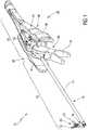
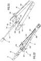
- Fig. 1shows a perspective view of an instrument 10, the distal end facing the viewer and the proximal end facing away from the viewer.
- the instrument 10is designed as an instrument for neurosurgery and / or brain surgery. Accordingly, the instrument 10 may also be referred to as a neurosurgical instrument.
- the instrument 10has a shaft 12, which is at least partially formed by a tube 14 which is designed rigid.
- the tube 14defines a longitudinal axis of the shaft 12 that extends from a proximal end to a distal end.
- the shaft 12is associated with a joint portion 16 which in Fig. 1 is shown by way of example in a deflected and / or angled position.
- an effector 20is added to the distal end of the shaft 12, which is designed approximately as a gripper.
- the effector 20comprises a first jaw part 22 and a second jaw part 24. In Fig. 1 the effector 20 is shown in an open position in which the jaws 22, 24 are opened.
- a handling section 30Adjoining the proximal end of the shaft 12 is a handling section 30 in which the instrument 10 can be received and guided by a user, such as a surgeon or surgeon.
- the shaft 12defines a distal portion of the instrument.
- the handling portion 30defines a proximal portion of the instrument 10.
- the instrument 10further includes a deflection mechanism 32 for controlling the deflection and / or angular position of the hinge portion 16.
- the deflection mechanism 32is exemplarily provided with a control lever 34.
- the instrument 10has an actuating mechanism 40 for the effector 20.
- the actuating mechanism 40includes a handle 42 having a first arm 44 and a second arm 46. The arms 44, 46 extend distally from the proximal end of the handle portion 30 toward the shaft 12.
- the instrument 10has an interface 48 to which a closure clip 50 is assigned.
- the instrument 10can be disassembled into a shaft assembly 52 and a handle 54.
- the shaft assembly 52is a distal assembly.
- the handle 54denotes a proximal assembly.
- the shaft assembly 52is at least partially associated with the shaft 12.
- the handle 54is at least partially associated with the handling section 30.
- at least the deflection mechanism 32in particular the control lever 34, is assigned to the shaft assembly 52, that is to say disposed distally from the interface 48.
- Other designs and Assignmentsconcern the deflection mechanism 32 and / or the actuating mechanism 40 are conceivable.
- the lock bracket 50is configured to lock the shaft assembly 52 and the handle 54 together.
- the lock bracket 50is pivotable to allow release of the shaft assembly 52 from the handle 54.
- FIGS. 2, 3, 4 and 5directed.
- Fig. 1 . 2 and FIG. 4show that the handle 42 of the actuating mechanism 40 is received at a distal end of the handle 54, wherein the arms 44, 46 are deflectable.
- the arms 44, 46extend at least partially laterally from the closure bar 50 and from the control lever 34 of the deflection mechanism 32.
- the closure bar 50 and the control lever 34are arranged at least in sections between the arms 44, 46 of the handle 42.
- the in Fig. 1shown configuration good handling.
- the instrument 10also has a low center of gravity that facilitates holding and guiding the instrument 10.
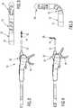
- FIGS. 2 and 4show broken side views of the in Fig. 1 perspective illustrated instruments 10.
- Fig. 2shows a first pivot state.
- Fig. 4shows a second panning state.
- Fig. 3shows an enlarged view of a distal portion of the shaft 12 of the instrument 10, wherein the pivot state of the hinge portion 16 of the in Fig. 2 shown state corresponds.
- Fig. 5shows an enlarged view of the distal end of the shaft, wherein the in Fig. 5 shown state of the joint portion 16 in the Fig. 4 shown pivot state corresponds.
- FIGS. 2 and 4From the FIGS. 2 and 4 It can be seen that the control lever 34 of the deflection mechanism 32 is pivotable to pivot the hinge portion 16 between a first curvature state (FIG. Fig. 2 ) and a second curvature state ( Fig. 4 ) to move.
- Fig. 2shows a state in which the hinge portion 16 is centered and is oriented concentrically to the longitudinal axis of the shaft 12.
- Fig. 5shows a state in which the hinge portion 16 is maximally deflected or angled.
- FIGS. 2, 7 and 8illustrated in more detail.
- the in the FIGS. 4 and 5 shown second curvature stateis based on the FIGS. 9, 10 and 11 illustrated in more detail.
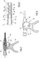
- Fig. 6 and Fig. 9illustrate a pivoting of the control lever 34th Fig. 7 and Fig. 10 show corresponding cut views.
- Fig. 8shows a section through the hinge portion 16 in the first state of curvature.
- Fig. 11shows a section through the hinge portion 16 in the second state of curvature.
- Fig. 6 and Fig. 7show that the deflection mechanism 32 further comprises a control unit 58, which is associated with the control lever 34.
- the control lever 34is pivotally received on a bearing piece 60.
- a pivot axis 62 for the control lever 34is in Fig. 6 and Fig. 9 designated 62.
- the control lever 34is pivoted about the pivot axis 62.
- Fig. 7 and Fig. 10the control lever 34 according to exemplary embodiments with adjusting screws 66, 68 which allow a fine adjustment and / or adjustment of angular positions of the control lever 34 with respect to the bearing piece 60.
- Fig. 7shows the control unit 58 in a state in which the hinge portion 16 is in the first curvature state, see. also Fig. 8 , In this state, the adjusting screw 66 can contact the bearing piece 60 and provide there an adjustable stop for the control lever 34.
- Fig. 10illustrates a second state of the control lever 34
- the in Fig. 11 shown second curvature state of the hinge portion 16corresponds.
- the adjusting screw 68contacts the bearing piece 60.
- an adjustable stopavailable through which a fine adjustment and / or adjustment of the pivot state of the control lever 34 with respect to the bearing piece 60 can be done.
- FIGS. 7 and 10show further that the control lever 34 and the bearing piece 60 via sliders 72, 74 are coupled together.
- a first slider 72is associated with a first tension member 76.
- a second slider 74is associated with a second tension member 78, see. also Fig. 8 and Fig. 11 ,
- the slider 72is connected to the pulling member 76 at a proximal end of the traction member 76 for driving engagement.
- the slider 74is connected to the pulling member 78 at a proximal end of the traction member 78 for moving engagement.
- the tension member 76is exemplified as a pull wire 80.
- the tension member 78is exemplified as a pull wire 82.
- the tension elements 76, 78are preferably made of a highly elastic material. This may, for example, be nitinol and / or a similar superelastic alloy.
- the curved representation in Fig. 11shows that the first tension member 76 may also be referred to as an inner tension member.
- the tension member 78may also be referred to as an outer tension member, based on the respective radius of curvature of the tension members 76, 78.
- the pull wire 80may also be referred to as an inner pull wire.
- the puller wire 82may also be referred to as an outer puller wire.
- pivoting the control lever 34 toward the distal end of the instrument 10causes the hinge portion 16 to deflect to an angled position.
- Turned upgenerates a pivoting movement of the control lever 34th in the direction of the proximal end of the instrument 10, a pull on the tension member 78.
- the hinge portion 16is moved from the curved back to the rectilinear, central position.
- the hinge portion 16is based on the Fig. 8 and the Fig. 11 illustrated in more detail.
- the hinge portion 16illustratively includes a hinge member 88 and a hinge member 90 received between a proximal hub 92 and a distal hub 94.
- Pivot axes 96, 98, 100illustrate that the assembly comprising the connector 92, the hinge member 88, the hinge member 90, and the connector 94 are all pivotable, each including relative pivoting of adjacent members.
- the hinge members 88, 90 and preferably also the connecting pieces 92, 94are preferably provided with stops 106, 108, 110, 112.
- Fig. 8are exemplified opposing stops 106, 108, wherein the stop 106 is associated with the hinge member 88 and the stop 108 of the hinge member 90. It is understood that there are more attacks on this site.
- Fig. 11shows that in the curved state of the hinge portion 16, the stops 106, 108 contact each other.
- Fig. 11shows a similar way in that stops 110, 112 are further provided which define a rectilinear, extended orientation of the hinge portion 16.
- the stop 110is associated with the hinge member 88.
- the stop 112is associated with the hinge member 90.
- Other involved membersare similarly attacked.
- a comparison between Fig. 8 and Fig. 11shows that the stops 110, 112 are used to define the rectilinear, central orientation of the hinge portion 16. At least the central position of the hinge portion 16 is defined by the stops 110, 112 highly accurate and repeatable.
- the stops 106, 108may be configured to provide high positioning accuracy and repeatability even for the angled / deflected state of the hinge portion 16.
- Fig. 8 and Fig. 11 embodiment shownfurther shows that the tension elements 76, 78 are indeed used to pivot the hinge portion 16 and / or due.
- the actual positioning in the respective end positionsis, however, by the stops 106, 108 for in Fig. 11 shown position and the stops 110, 112 for in Fig. 8 shown position.
- FIGS. 12 and 13An exemplary embodiment of the control unit 58 for the deflection mechanism 32 is further illustrated.
- FIGS. 12 and 13each show exploded perspective views, the views are based on different orientations.
- control lever 34is made in two parts and provided with a first side part 118 and a second side part 120.
- the side parts 118, 120can be screwed together approximately.
- the first side part 118is provided with a bearing recess 122.
- the second side part 120is provided with a bearing recess 124.
- a bearing pin 126is provided which is receivable in a bearing recess 128 on the bearing piece 60.
- the side part 118is received on the bearing pin 126 via the bearing recess 122.
- the side part 120is received on the bearing pin 126 via the bearing recess 124. Accordingly, the control lever 34, which includes the side parts 118, 120, can be pivoted about the bearing pin 126.
- bearing pin 126may also be integrally formed on the bearing piece 60. According to this exemplary embodiment, no separate bearing recess 128 is provided on the bearing piece 60.
- FIGS. 12 and 13are also indicated by 130, 132 elastic clamping body, which are provided for increasing the friction or position assurance.
- the clamping body 130, 132may be exemplified as so-called. O-rings.
- the FIGS. 12 and 13show that each lateral end of the bearing pin 126 has two clamping bodies 130, 132 are assigned.
- the one or more clamping body 130is / are provided between the bearing pin 126 and the bearing recess 122.
- the one or more clamping body 132is / are provided between the bearing pin 126 and the bearing recess 124.
- the side parts 118, 120 of the control lever 34also have mounting holes 134, 136.
- the provided on the side part 118 mounting opening 134includes, for example, a thread.
- the mounting opening 136 provided on the side part 120comprises by way of example a through-hole for a screw.
- control lever 34In the assembled state of the control lever 34 is pivotable about the bearing pin 126, wherein the clamping body 130, 132 cause a friction increase, which can be reflected in a self-locking or position assurance. In other words, it is preferred if the control lever 34 automatically and without external action maintains its actual pivot position relative to the bearing piece 60.
- the corresponding frictional forcesare primarily generated by the clamping body 130, 132, which are received with bias between the bearing piece 60 and the side part 118 and between the bearing piece 60 and the side part 120.
- FIG. 14shows a sectional view of the control unit 58 for the deflection mechanism 32nd
- Fig. 15shows an isolated side view of a control lever 34.
- a first guide track 138 and a second guide track 140is formed on the control lever 34. Furthermore, in particular FIGS. 12 and 13 in that a first guide track 144 and second guide track 146 are formed on the bearing piece 60.
- the slider 72 for the first tension member 76is added in the assembled state in the guide track 144 of the bearing piece 60 and the guide track 138 of the control lever 34.
- the slider 74, which is associated with the tension element 78,is received in the guide track 146 of the bearing piece 60 and the guide track 140 of the control lever 34.
- Fig. 15shows that the guideways 138, 140 are received on the control lever 34 in a certain way relative to the bearing recess 122, 124. This causes that upon pivoting of the control lever 34 about the pivot axis 62, the tension members 76, 78 are not moved by the same amount. This measure has the advantage that different bending radii of the tension elements 76, 78 can be compensated, cf. this too Fig. 11 ,
- FIGS. 12 to 15 illustrated embodiment of the control unit 58Another goal of the basis of the FIGS. 12 to 15 illustrated embodiment of the control unit 58 is that, if possible, both tension members 76, 78 are simultaneously under tension when the control lever 34 is pivoted to the proximal or distal. As already mentioned in connection with Fig. 8 and Fig. 11 explained, it is basically sufficient to pull the first tension member 76 for deflecting / bending. Turned over, it is sufficient to move the second pulling element 78 distally in order to return the articulated section 16 to an extended, central position.
- control unit 58is designed such that in each case both tension members 76, 78 are at least slightly biased in their longitudinal direction. This has the advantage that the deflection mechanism 32 is designed with low backlash or almost no play. In particular, in a reversal of movement can thus be avoided excessive play.
- a passage 150extends between a distal end and a proximal end.
- the passage 150is, for example, concentric with a longitudinal axis through the shaft 12.
- Fig. 14shows a state of the instrument 10, in which the shaft 12 and the bearing piece 60 are joined together, wherein in the shaft 12 a Thrust piece 154 is arranged, which extends through the passage 156 in the bearing pin 126.
- Fig. 12, Fig. 13 and Fig. 14show further that in addition to the tension elements 76, 78 and the thrust piece 154 on the shaft 12, in particular in the tube 14, is received.
- a passage 156is provided for the thrust piece 154, so that it can be passed through the bearing pin 126 centrally.
- a pressure piece 160is provided, which is connected to the thrust piece 154.
- a compression spring or springwhich is received between the pressure piece 160 and a stop 162 on the bearing piece 60 to urge the thrust piece 154 toward the proximal end. This too can contribute to the low-backlash or even backlash-free design of the control unit 58 and the deflection mechanism 32.
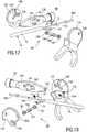
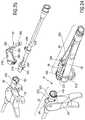
- FIGS. 16, 17 and 18show an effector 20 received at the distal end of the shaft, which is exemplified as a gripper 164. It is understood that the effector 20 may alternatively be designed as a pair of pliers, pincers, scissors, clamp and in a similar manner.
- FIGS. 16, 17 and 18show the effector 20 in an open position.
- FIGS. 16, 17 and 18show the effector 20 in a closed position.
- Fig. 19corresponds with Fig. 16
- Fig. 20corresponds with Fig. 17
- Fig. 21corresponds with Fig. 18 ,
- a head piece 166is included, which is exemplified as a clevis 168, executed.
- the headpiece 166comprises a first side part 170 and a second side part 172.
- a coupling piece 174is slidably received, wherein the coupling piece 174 comprises a flat piece 176 at its distal end. From the flat piece 176 from a driver 178 extends and another driver 180. The drivers 178, 180 are received on opposite sides of the sheet 176.
- the coupling piece 174is coupled to the first jaw part 22 and the second jaw part 24.
- a driving recess 186is provided on the first jaw part 22.
- a second driving recess 188is provided on the second jaw part 24.
- the driver 178engages in the driving recess 186 on the jaw part 22 a.
- the driver 180engages in the driving recess 188 on the second jaw part 24.
- first jaw part 22has a projection 194.
- second jaw part 24has a projection 196.
- the first projection 194is associated with a bearing recess 198 on the head piece 166.
- the second projection 196is associated with a bearing recess 200 on the head piece 166.
- the projection 194extends from a flat piece 202 of the first jaw part 22.
- the projection 196extends from a flat piece 204 of the second jaw part 24.
- a guide track 206is formed in the flat piece 202.
- a guide track 208is formed in the flat piece 204.
- a guide pin 214is further provided, which projects through a guide recess 216 in the sheet 176 of the head piece 166.
- the guide pin 214is received on a seat 222 on the side part 170 and a seat 224 on the side part 172.
- the coupling piece 174 and the first jaw part 22 and the second jaw part 24are received between the side parts 170, 172, in particular via their flat pieces 176, 202, 204.
- the flat piece 176 of the coupling piece 174is between the flat pieces 202, 204 of the jaw parts 22, 24 added.
- the guide pin 214 extending between the seats 222, 224also extends through the guide track 206 on the first jaw part 22, the guide track 208 on the jaw part 24 and the guide recess 216 in the flat piece 176 of the coupling piece 174.
- FIGS. 16, 17 and 18A comparison of FIGS. 16, 17 and 18 With 19, 20 and 21 shows that the coupling piece 174 is pushed distally to close the jaw parts 22, 24. If the coupling piece 174 is pushed or pushed proximally, the jaw parts 22, 24 open.
- the pusher 154may be made of a highly elastic material or even a superelastic alloy such as nitinol.
- the actuating mechanism 40 for the effector 20is illustrated in greater detail.
- the handle 42 of the actuating mechanism 40is received at the distal end of the instrument 10.
- the handle 42is received on a support shaft 228, which is connected to the bearing piece 60 and to the shaft 12 in series.
- Fig. 23For reasons of illustration, the bearing piece 60 and the support shaft 228 are hidden.
- the arms 44, 46 of the handle 42 in the FIGS. 22 and 23not explicitly shown (cf Fig. 1 ).
- the arms 44, 46are designed as attachments.
- the actuating mechanism 40includes a coupling mechanism 230 having a slider 232 which is couplable to the pressure pad 160 provided at the proximal end of the pusher 154.
- the slider 232comprises a quiver-like shaped seat 234 and an adjoining flat piece 236.
- the slider 232can be plugged onto the pressure piece 160 in order to press it in the direction of the distal end of the instrument.
- a counteracting forceis generated by the spring 158, which in Fig. 23 is indicated.
- the installation state of the springcan be approximately as shown in Fig. 14 are removed, cf. this too Fig. 26 ,
- the handle 42includes actuating portions 238, 240, which extend approximately pliers from proximal to distal. Between the operating sections 238, 240 extends the support shaft 228, at the distal end of the handle 42 is attached.
- the actuating portion 238is coupled via a coupling member 246 with the flat piece 236 of the quiver-like slide 232.
- the actuating portion 240is connected via a coupling member 248 with the sheet 236.
- the coupling members 246, 248have on the flat piece 236 of the slider 232 on the same pivot point.
- the coupling member 246is pivotally received on the actuating portion 238 via a bearing pin 254.
- the coupling member 248is pivotally received on the actuating portion 240 via a bearing pin 256.
- the coupling links 246, 248extend through passages 250 formed in the carrier shaft 228, cf. also the representation of the carrier shaft 228 with the passage 250 in Fig. 25 ,
- a hinge portion 262is formed at the operating portion 238, a hinge portion 262 is formed.
- a hinge portion 264is formed, see. Fig. 22 .
- the joint sections 262, 264may, for example, have a material weakening, in order to provide a cohesive pivot joint and / or a virtual pivot point or a virtual pivot axis for the actuating sections 238, 240.
- the actuating mechanism 40 for the effector 20is designed with little play or even play.
- the pressure piece 160is formed, which is urged by the spring 158 toward the proximal end of the instrument. From the distal end of the coupling mechanism 230 acts via the slider 232 on the pressure piece 160 and urges this against the force of the spring 158 toward the proximal end of the instrument 10 when the actuating portions 238, 240 are moved towards each other. If also the coupling mechanism 230 acts at least with a slight bias on the pressure piece 160, this can be added without play or play "floating" between the coupling mechanism 230 and the spring 158.
- the coupling mechanism 230can be designed such that even in a state unloaded from the outside, the actuating portions 238, 240 urge inwards and thus a biasing force is generated on the slider 232.
- FIGS. 24 and 25 and with additional reference to FIGS. 26 and 27an exemplary embodiment of the interface 48 between the shaft assembly 52 and the handle 54 is illustrated in more detail.
- the interface 48can be locked or unlocked via a locking clip 50.
- the interfacecomprises a male fitting portion 270 and a female fitting portion 272.
- the male fitting portion 270may also be referred to as an inner portion.
- the female fitting part 272may also be referred to as an outer part.
- the male fitting portion 270is insertable into the female fitting portion 272 to align the stem assembly 52 and the handle 54 with each other.
- a holding portion 276is formed, such as in the form of a step or a paragraph.
- the closure bar 50has a holding arm 278 at its distal end, cf. in particular the representation in Fig. 25 showing the closure bar 50 in an insulated form.
- the closure bar 50can engage the holding section 276 in order to lock the joined state of the male fitting part 270 with the female fitting part 272.
- the holding arm 278includes, for example, a position securing portion 280, to which a release portion 282 adjoins, cf. in turn Fig. 25 ,
- the position securing portion 280includes a bottleneck.
- the release portion 282includes a widening. Together, the position securing portion 280 and the releasing portion 282 may form a keyhole contour.
- the closure bracket 50is over a Joint 288 pivotally received on a bearing piece 286.
- the bearing piece 286is arranged on the support shaft 228.
- the position securing section 280 or the release section 282is aligned with the holding section 276.
- the closure bar 50is pivoted in such a way that the release section 282 is oriented substantially concentrically with respect to the carrier shaft 228 or to the male fitting part 270. Then, the male fitting part 270 can be joined with the female fitting part 272, cf. also the state in Fig. 26 ,
- the shutter bracket 50can be pivoted such that the position securing portion 280 engages the holding portion 276 to secure the joining state between the male fitting portion 270 and the female fitting portion 272.
- an opposing movementcan be applied to the closure clip 50 in order to guide the position securing section 280 out of the latched state on the holding section 276. It is conceivable to receive the closure bar 50 on the carrier shaft 228 in such a way that a bias is produced in the direction of the locked state. This can increase the security additionally. The risk of incorrect operation can be reduced.
- the position securing portion 280 on the holding arm 278 of the closure bracket 50is designed so that disengagement from the holding portion 276 is possible only by elastic deformation, such as by a lateral expansion, of the closure bracket 50 in the region of the holding arm 278. In this way, a certain force must be applied to disengage the position securing portion 280 and to make the releasing portion 282, which has a larger cross section, coincide with the holding portion 276. Furthermore, it is conceivable to form a recess 290 on a back of the closure strap 50, which opens into the position securing section 280. In this way, a defined deformability of the holding arm 278 in the region of the position securing portion 280 is given.
- a groove 292is formed by way of example on the female fitting part 272.
- the groove 292extends axially and is open at its proximal end.
- a guide pin 294is arranged, which is oriented radially to a longitudinal axis of the instrument 10. When joining the male fitting 270 with the female fitting 272, the guide pin 294 can engage the groove 292 to secure the desired rotational position.
- FIGS. 26 and 27illustrate that on the male fitting part 270, a conical surface 300 is formed, which is followed by a cylindrical surface 304.
- a conical surface 302is formed, to which a cylindrical surface 306 adjoins.
- the cone surface 302 and the cylindrical surface 306are inner surfaces.
- the cone surface 300 and the cylindrical surface 304are outer surfaces.
- the fitting parts 270, 272may be provided primarily with the cylindrical surfaces 304, 306, which ensure a concentric design.
- FIGS. 26 and 27further illustrate that the interface 48 also includes the pusher 160 on the side of the stem assembly 52 and the pusher 232 on the side of the handle 54. Sliding motion may be transmitted to the pusher 160 via the pusher 232 to displace the pusher 154 toward the distal end of the instrument to control the effector 20. About the slider 232 primarily pressure forces are transmitted to the pressure piece 160.
Landscapes
- Health & Medical Sciences (AREA)
- Life Sciences & Earth Sciences (AREA)
- Surgery (AREA)
- Engineering & Computer Science (AREA)
- Medical Informatics (AREA)
- Veterinary Medicine (AREA)
- Biomedical Technology (AREA)
- Heart & Thoracic Surgery (AREA)
- Nuclear Medicine, Radiotherapy & Molecular Imaging (AREA)
- Molecular Biology (AREA)
- Animal Behavior & Ethology (AREA)
- General Health & Medical Sciences (AREA)
- Public Health (AREA)
- Ophthalmology & Optometry (AREA)
- Pathology (AREA)
- Biodiversity & Conservation Biology (AREA)
- Robotics (AREA)
- Surgical Instruments (AREA)
Abstract
Translated fromGermanDescription
Translated fromGermanDie vorliegende Offenbarung betrifft ein chirurgisches Instrument, insbesondere ein Instrument, das für die Neurochirurgie nutzbar ist. Ein solches Instrument kann auch als neurochirurgisches Instrument bezeichnet werden. Ein weiteres Anwendungsgebiet für derartige Instrumente ist das Gebiet der Hirnchirurgie. Die Begriffe "Hirnchirurgie" und "Neurochirurgie" haben einen sich zumindest teilweise überlappenden Bedeutungsgehalt.The present disclosure relates to a surgical instrument, in particular an instrument useful for neurosurgery. Such an instrument may also be referred to as a neurosurgical instrument. Another field of application for such instruments is the field of brain surgery. The terms "brain surgery" and "neurosurgery" have an at least partially overlapping meaning.
Chirurgische Instrumente im Sinne der vorliegenden Offenbarung umfassen einen Schaft, einen proximalen Handhabungsabschnitt an einem proximalen Ende des Schaftes, und einen distalen Effektor an einem distalen Ende des Schaftes, wobei der Effektor über einen Betätigungsmechanismus gesteuert wird. Bei dem Effektor kann es sich etwa um eine Zange, Schere, Schneide, Klemme, Koagulationsklemme und dergleichen handeln. Ferner ist die Gestaltung des Effektors als Kürette, Biopsiezange oder in ähnlicher Weise vorstellbar.Surgical instruments in the sense of the present disclosure comprise a shaft, a proximal handling section at a proximal end of the shaft, and a distal effector at a distal end of the shaft, wherein the effector is controlled via an actuating mechanism. The effector may be, for example, a pair of pliers, scissors, blade, clamp, coagulation clamp and the like. Furthermore, the design of the effector as a curette, biopsy forceps or similarly conceivable.
Allgemein betrifft die vorliegende Offenbarung Instrumente auf dem Gebiet der minimal-invasiven Chirurgie. In diesem Zusammenhang ist anzumerken, dass im Bereich der Neurochirurgie und/oder der Hirnchirurgie sehr hohe Anforderungen an die Kompaktheit des Instruments, die Führungsgenauigkeit, die Bedienbarkeit sowie die Präzision allgemein bestehen. Die vorstehend beschriebenen Anforderungen gelten grundsätzlich auch für chirurgische Instrumente allgemeiner Art, wie etwa endoskopische und/oder laparoskopische Instrumente. Jedoch gelten für neurochirurgische Instrument und/oder gehirnchirurgische Instrumente noch andere Maßstäbe und Anforderungen. Es hat sich gezeigt, dass Konstruktionsprinzipien, die bei chirurgischen Instrumenten und invasiven Instrumenten allgemeiner Art umsetzbar sind, nicht direkt auf neurochirurgische und/oder hirnchirurgische Instrumente übertragbar sind.Generally, the present disclosure relates to instruments in the field of minimally invasive surgery. In this context, it should be noted that in the field of neurosurgery and / or brain surgery very high demands on the compactness of the instrument, the leadership accuracy, operability and precision generally exist. In principle, the requirements described above also apply to surgical instruments of general type, such as endoscopic and / or laparoscopic instruments. However, other standards and requirements apply to neurosurgical instruments and / or brain surgical instruments. It has been found that design principles that can be implemented in surgical instruments and invasive instruments of a general nature are not directly transferable to neurosurgical and / or brain surgical instruments.
Dies schließt nicht aus, dass Instrumente im Sinne der vorliegenden Offenbarung für die HNO-Chirurgie (Hals-Nasen-Ohren Chirurgie) und andere klassische Bereiche der Chirurgie nutzbar sind. Allgemein können derartige Instrumente dann genutzt werden, wenn ein geringer Platzbedarf und eine gewisse Flexibilität gefordert ist. Instrumente gemäß der vorliegenden Offenbarung können als Miniatur-Instrumente gestaltet sein, insbesondere im Hinblick auf ihren Schaftdurchmesser.This does not exclude that instruments within the meaning of the present disclosure are useful for ENT (otolaryngology surgery) surgery and other classical areas of surgery. In general, such instruments can be used when a small footprint and a certain flexibility is required. Instruments according to the present disclosure may be designed as miniature instruments, particularly with regard to their shank diameter.
Im Sinne der vorliegenden Offenbarung ist eine proximale Seite eine vom Patienten abgewandte und einem Operateur zugewandte Seite des Instruments. Demgemäß ist eine distale Seite eine dem Patienten zugewandte und vom Operateur abgewandte Seite des Instruments. Insbesondere auf dem Gebiet der invasiven Chirurgie wird das distale Ende des Instruments in das Körperinnere des Patienten eingeführt. Üblicherweise wird das Instrument am proximalen Ende gehalten bzw. geführt, wobei auch Ausführungsformen vorstellbar sind, bei denen sich das proximale Ende des Instruments über den Handhabungsabschnitt hinaus erstreckt.For the purposes of the present disclosure, a proximal side is a side of the instrument facing away from the patient and facing a surgeon. Accordingly, a distal side is a side of the instrument facing the patient and remote from the surgeon. Particularly in the field of invasive surgery, the distal end of the instrument is inserted into the interior of the patient's body. Usually, the instrument is held or guided at the proximal end, wherein embodiments are also conceivable in which the proximal end of the instrument extends beyond the handling section.
Aus der
Aus der
Aus der
Aus der
Aus der
Eine neurochirurgische oder hirnchirurgische Behandlung umfasst bspw. das Setzen eines Zugangs an der Schädeldecke eines Patienten. Beispielhaft wird eine Bohrung in die Schädeldecke eingebracht, durch die ein Instrument in den Schädel einführbar ist. Bekannte neurochirurgische Instrumente, vergleiche die obige
Die Zugänge in das Körperinnere des Patienten, insbesondere in den Kopf und/oder den Wirbelsäulenbereich, können nicht beliebig groß ausgeführt werden. Das Ziel ist es, Traumata für den Patienten möglichst zu minimieren. Diese Konstellation kann jedoch dazu führen, dass das Instrument einen gewünschten Zielort im Körperinneren, etwa im Kopf des Patienten, schlichtweg nicht erreichen kann, da der Schaft als Ganzes nicht beliebig verschwenkbar ist. Dies würde unter Umständen dazu führen, dass ein weiterer Zugang hergestellt werden muss.The accesses to the inside of the body of the patient, in particular in the head and / or the spinal area, can not be made arbitrarily large. The goal is to minimize trauma for the patient as much as possible. However, this constellation can lead to the instrument simply not being able to reach a desired target location in the interior of the body, for example in the patient's head, since the shaft as a whole can not be pivoted at will. This might lead to the need for further access.
In anderen Bereichen der Chirurgie, etwa auf dem Gebiet der laparoskopischen Chirurgie, sind abwinkelbare Instrumente bekannt. Solche Instrumente weisen Schwenkmechanismen und/oder Auslenkmechanismen auf, die etwa am Schaft selbst oder am distalen Ende des Schaftes ausgebildet sind. Auf diese Weise kann ein zusätzlicher Bewegungsfreiheitsgrad für das Instrument bereitgestellt werden. Beispielhaft kann eine am distalen Ende des Instruments aufgenommene Zange insgesamt verschwenkt werden.In other areas of surgery, such as in the field of laparoscopic surgery, angled instruments are known. Such instruments have pivoting mechanisms and / or deflection mechanisms which are formed approximately on the shaft itself or on the distal end of the shaft. In this way, an additional degree of freedom of movement for the instrument can be provided. By way of example, a pair of pliers received at the distal end of the instrument can be pivoted in total.
Auf diese Weise können etwa Bereiche im Körperinneren erreicht werden, die seitlich von einer gedachten Hauptachse des Schaftes beabstandet sind. Wie vorstehend bereits ausgeführt, weisen jedoch konventionelle endoskopische Instrumente und/oder laparoskopische Instrumente grundsätzlich größere Abmessungen auf, als neurochirurgische Instrumente. Beispielsweise kann ein Schaftdurchmesser eines laparoskopischen Instruments 10 mm, 12 mm, oder sogar noch mehr betragen. Der Schaftdurchmesser eines neurochirurgischen Instruments, das etwa auf dem Gebiet der Hirnchirurgie genutzt wird, ist deutlich kleiner. Hier kann ein Schaftdurchmesser etwa maximal 3,5 mm, vorzugsweise maximal 3,0, mm, weiter bevorzugt etwa 2,7 mm oder gar weniger betragen. Schon aus diesem Grund können grundsätzlich bekannte Konstruktionsprinzipien für auslenkbare und/oder abwinkelbare Instrumente nicht ohne weiteres auf das Gebiet der Neurochirurgie übertragen werden.In this way, it is possible to achieve, for example, areas in the interior of the body which are laterally spaced from an imaginary main axis of the shaft. However, as stated above, conventional endoscopic instruments and / or laparoscopic instruments generally have larger dimensions than neurosurgical instruments. For example, a shaft diameter of a laparoscopic instrument may be 10 mm, 12 mm, or even more. The shaft diameter of a neurosurgical instrument used in the field of brain surgery, for example, is much smaller. Here, a shaft diameter may be about 3.5 mm at the maximum, preferably at most 3.0 mm, more preferably about 2.7 mm or even less. For this reason alone, basically known design principles for deflectable and / or angled instruments can not readily be transferred to the field of neurosurgery.
Eine weitere Anforderung, die für neurochirurgische und/oder hirnchirurgische Instrumente im Besonderen gilt, ist die Genauigkeit der Bewegung und/oder die Positionierbarkeit, Positioniergenauigkeit, sowie die Positionierwiederholbarkeit.Another requirement that applies to neurosurgical and / or cerebral surgical instruments in particular is the accuracy of the movement and / or the positionability, positioning accuracy, as well as the positioning repeatability.
Insbesondere bei Operationen, die im Gehirn des Patienten vorgenommen werden, können kleinste Abweichungen und Ungenauigkeiten zu Beschädigungen des benachbarten Gewebes führen. Auch hier gilt, dass sich Gestaltungsprinzipien bekannter abwinkelbarer Instrumente aus dem Bereich der laparoskopischen Chirurgie nicht ohne weiteres auf den Bereich der Neurochirurgie übertragen lassen.In particular, in operations that are performed in the brain of the patient, the slightest deviations and inaccuracies can lead to damage to the adjacent tissue. Here too, the principles of design of known articulated instruments from the field of laparoscopic surgery can not be easily transferred to the field of neurosurgery.
Effektive Wege und Bewegungen, die das Instrument bspw. im Schädel des Patienten ausführt, sind sehr klein. Dies bedingt eine ausgeprägte Feinfühligkeit und Führungsgenauigkeit der Instrumente und der daran/darin verbauten Mechanismen. Bei neurochirurgischen Instrumenten hat die Ergonomie und Handhabbarkeit eine sehr hohe Bedeutung. Das Instrument soll feinfühlig und hochgenau positioniert werden können. Die Positionierung soll mit hoher Wiederholgenauigkeit erfolgen.Effective paths and movements that the instrument performs, for example, in the skull of the patient, are very small. This requires a pronounced sensitivity and guidance accuracy of the instruments and the mechanisms built into them. In neurosurgical instruments, ergonomics and manageability are very important. The instrument should be able to be positioned sensitively and with high precision. The positioning should be done with high repeatability.
Grundsätzlich ist es vorstellbar, neurochirurgische Instrumente mit nicht auslenkbaren/abwinkelbaren Schäften zu nutzen. Jedoch weisen derartige Instrumente nur einen sehr begrenzten Aktionsradius auf. Es gibt Extremfälle, bei denen Instrumente mit geraden Schäften das Arbeitsgebiet schlichtweg nicht erreichen können, da kein geeigneter Zugang (etwa Bohrung in die Schädeldecke) platziert werden kann.In principle, it is conceivable to use neurosurgical instruments with non-deflectable / bendable shafts. However, such instruments have only a very limited range of action. There are extreme cases in which instruments with straight shanks simply can not reach the working area because no suitable access (such as a hole in the skull) can be placed.
Ferner besteht der Wunsch nach zerlegbaren Instrumenten auch auf dem Gebiet der Neurochirurgie. Ein zerlegbares Instrument weist zumindest eine Schnittstelle auf, an der Baugruppen des Instruments definiert voneinander lösbar sind. Dies kann bspw. eine Schaftbaugruppe und ein Griffstück des Instruments betreffen. Es hat sich gezeigt, dass die Gestaltung zerlegbarer Instrumente häufig zu einer Verringerung der Genauigkeit führt. Mit anderen Worten ist zu beobachten, dass entsprechende Schnittstellen, die für die Zerlegbarkeit der Instrumente erforderlich sind, häufig einen Anstieg des mechanischen Spiels und folglich eine Verringerung der Führungsgenauigkeit bedingen.Furthermore, there is a desire for collapsible instruments also in the field of neurosurgery. A dismountable instrument has at least one interface on which subassemblies of the instrument can be detached from one another. This may, for example, relate to a shaft assembly and a handle of the instrument. It has been found that the design of dismountable instruments often leads to a reduction in accuracy. In other words, it can be observed that corresponding interfaces required for the dismantling of the instruments often cause an increase of the mechanical clearance and consequently a reduction of the guidance accuracy.
Ferner besteht bei chirurgischen Instrumenten, die abwinkelbar/auslenkbar gestaltet sind, häufig eine Wechselwirkung zwischen den beteiligten Freiheitsgraden. Mit anderen Worten kann bspw. eine Betätigung eines Effektors (etwa Öffnen und Schließen einer Zange) gewisse Auswirkungen auf einen Mechanismus für die Auslenkung/Abwinkelfunktion des Instruments haben. Auch dies kann grundsätzlich zu einer Verringerung der Genauigkeit und zu einer Erhöhung des Spiels im System führen.Furthermore, there is often an interaction between the degrees of freedom involved in surgical instruments that are designed bendable / deflectable. In other words, for example, an operation of an effector (such as opening and closing of a pair of pliers) may have some effect on a mechanism for the deflection / angling function of the instrument. Again, this can basically lead to a reduction in accuracy and an increase in game play in the system.
Vor diesem Hintergrund liegt der vorliegenden Offenbarung die Aufgabe zugrunde, ein chirurgisches Instrument, insbesondere ein für die Neurochirurgie und/oder Hirnchirurgie geeignetes Instrument, anzugeben, das mit hoher Genauigkeit und Präzision bedienbar ist. Freiheitsgrade des Instruments sollen präzise und mit hoher Wiederholgenauigkeit steuerbar sein. Das Instrument ist möglichst mit nur einem geringen Spiel in den beteiligten Bewegungsmechanismen für die Freiheitsgrade versehen. Vorzugsweise ist das Instrument zerlegbar gestaltet, wobei sich ergebende Schnittstellen keine nachteiligen Auswirkungen auf die Genauigkeit bzw. das Spiel im System mit sich bringen. Es ist weiter bevorzugt, wenn das Instrument einen erweiterten Operationsradius bzw. ein erweitertes Operationsgebiet aufweist, so dass auch Gewebebereiche erreichbar sind, die bei gesetztem Instrument von einer Hauptachse des Schaftes beabstandet sind. Das Instrument soll eine spielarme oder gar spielfreie Ansteuerung sowohl des Effektors als auch einer Winkelposition/Auslenkposition des Effektors als Ganzes in Bezug auf den Schaft ermöglichen.Against this background, the present disclosure is based on the object of specifying a surgical instrument, in particular an instrument suitable for neurosurgery and / or brain surgery, which can be operated with high accuracy and precision. Degrees of freedom of the instrument should be controllable precisely and with high repeatability. The instrument is provided with as little as possible in the movement mechanisms involved for the degrees of freedom. Preferably, the instrument is designed separable, with resulting interfaces do not adversely affect the accuracy or the game in the system with it. It is further preferred if the instrument has an extended operating radius or an extended operating area, so that tissue areas can be reached which are spaced apart from a main axis of the shaft when the instrument is set. The instrument should enable a low-backlash or even backlash-free control of both the effector and an angular position / deflection position of the effector as a whole with respect to the shaft.
Gemäß einem ersten Aspekt wird die Aufgabe der Erfindung durch ein chirurgisches Instrument, insbesondere ein Instrument für die Neurochirurgie, gelöst, wobei das Instrument Folgendes aufweist:
- einen Schaft, wobei am Schaft ein Gelenkabschnitt ausgebildet ist, insbesondere ein Gelenkabschnitt, der ausgehend von einer Mittelposition einseitig auslenkbar ist,
- einen proximalen Handhabungsabschnitt an einem proximalen Ende des Schaftes,
- einen distalen Effektor an einem distalen Ende des Schaftes, und
- einen Auslenkmechanismus zur Steuerung eines Krümmungszustands des Gelenkabschnitts, der ein erstes Zugelement, insbesondere für eine Auslenkbewegung, sowie ein zweites Zugelement, insbesondere für eine Rückkehrbewegung, aufweist,
- a shaft, wherein a joint section is formed on the shaft, in particular a joint section, which is deflectable on one side starting from a central position,
- a proximal handling portion at a proximal end of the shaft,
- a distal effector at a distal end of the shaft, and
- a deflection mechanism for controlling a state of curvature of the joint section, which has a first tension element, in particular for a deflection movement, and a second tension element, in particular for a return movement,
Die Aufgabe der Erfindung wird auf diese Weise vollkommen gelöst.The object of the invention is completely solved in this way.
Erfindungsgemäß erlaubt nämlich die Gestaltung der Zugelemente eine spielarme oder sogar spielfreie Auslenkbewegung bzw. Ablenkung des Gelenkabschnitts. Dies wird dadurch erreicht, dass beide Zugelemente, von denen eigentlich beim Ausschwenken bzw. Einschwenken jeweils nur eines unter Spannung (Zugspannung) gesetzt wird, gemeinsam und richtungsgleich unter Spannung gesetzt werden. Dies bedeutet bspw., dass die Auslenkbewegung weiterhin über einen Zug am ersten Zugelement erfolgt.In accordance with the invention, the design of the tension elements permits a backlash-free or even backlash-free deflection movement or deflection of the joint section. This is achieved in that both tension elements, of which only one is actually placed under tension (tension) during pivoting or pivoting in each case, are put together in the same direction and under tension. This means, for example, that the deflection movement continues to take place via a train on the first tension element.
Jedoch wird das zweite Zugelement während der Auslenkbewegung zumindest abschnittsweise auch vorgespannt, wenn auch nur mit deutlich geringerer Spannung als das erste Zugelement. Bei der Rückkehrbewegung ist es umgekehrt, das zweite Zugelement wird entsprechend unter Zugspannung gesetzt. Auf das erste Element wird jedoch zumindest abschnittsweise eine Zugspannung aufgebracht, wenn auch mit einem deutlich niedrigerem Spannungsniveau als beim zweiten Zugelement. Der Begriff "abschnittsweise" bezieht sich hierbei bspw. auf einen bestimmten Schwenkwinkelbereich während der Verstellbewegung.However, the second tension element is at least partially biased during the deflection movement, albeit only with significantly lower tension than the first tension element. In the return movement, it is reversed, the second tension element is correspondingly under tension. However, at least sections of a tensile stress is applied to the first element, albeit with a significantly lower stress level than in the case of the second tension element. The term "sections" here refers, for example, to a specific pivot angle range during the adjustment.
Vorzugsweise ist das Instrument mit einem Gelenkabschnitt versehen, der einseitig auslenkbar bzw. abklappbar ist. Dies hat den Vorteil, dass eine Mittelposition, bei der bspw. der Gelenkabschnitt zu einer Längsachse des Schaftes ausgerichtet ist, einfach mechanisch definiert werden kann, etwa über geeignete Anschläge.Preferably, the instrument is provided with a hinge portion which is deflectable or hinged on one side. This has the advantage that a center position in which, for example, the joint portion is aligned to a longitudinal axis of the shaft, can be easily defined mechanically, for example via suitable stops.
Insgesamt ist der Auslenkmechanismus besonders spielarm, vorzugsweise spielfrei gestaltet. Dies erhöht die Positioniergenauigkeit und die Wiederholbarkeit der Positionierung des Instruments deutlich.Overall, the deflection is particularly low backlash, preferably designed free of play. This significantly increases the positioning accuracy and the repeatability of the positioning of the instrument.
Beispielsweise weisen chirurgische Instrumente, die für die Neurochirurgie und/oder die Hirnchirurgie geeignet sind, Schaftdurchmesser im Bereich von weniger als 3,5 mm, vorzugsweise von weniger als 3,0 mm, weiter bevorzugt von etwa 2,7 mm oder gar weniger auf. Obgleich diese Bauraumrestriktion die gestalterische Freiheit stark limitiert, kann die Spielarmut oder Spielfreiheit über die richtungsgleiche Vorspannung an den Zugelementen bewirkt werden.For example, surgical instruments suitable for neurosurgery and / or brain surgery have shaft diameters in the range of less than 3.5 mm, preferably less than 3.0 mm, more preferably about 2.7 mm or less. Although this space restriction strong the creative freedom limited, the low-backlash or backlash can be effected via the same directional bias on the tension elements.
Mit anderen Worten wird bspw. eine Zwangssteuerung bzw. eine überbestimmte Führung für das erste Zugelement und das zweite Zugelement bereitgestellt. Wäre dies nicht der Fall, würde bspw. bei der Auslenkbewegung das zweite Zugelement entlastet sein. Bei der Rückkehrbewegung wäre das erste Zugelement entlastet. Das jeweils andere Element wäre auf Zug beansprucht. Dies hätte den Nachteil, dass etwa dann, wenn die Richtung der Verstellbewegung des Gelenkabschnitts geändert wird, ein Spiel im Auslenkmechanismus vorhanden wäre, der zu einer verringerten Positioniergenauigkeit und Wiederholgenauigkeit führen würde.In other words, for example, a positive control or an overdetermined guide for the first tension element and the second tension element is provided. If this were not the case, for example, in the deflection movement, the second tension element would be relieved. In the return movement, the first tension element would be relieved. The other element would be claimed to train. This would have the disadvantage that, for example, if the direction of the adjustment movement of the joint portion is changed, a clearance would be present in the deflection mechanism, which would lead to a reduced positioning accuracy and repeat accuracy.
Da jedoch gemäß dem oben genannten Aspekt beide Zugelemente gemeinsam vorgespannt sind, kann eine solche Bewegungsumkehr spielarm oder sogar spielfrei erfolgen. Dies kann einerseits für Extremlagen des Gelenkabschnitts gelten, etwa für eine vollständig eingefahrene Position (Mittelposition) und/oder eine vollständig ausgefahrene Position (vollständig ausgelenkt) gelten. Gleichwohl ist eine Umkehrbewegung auch an einer Zwischenposition zwischen den Extrempositionen spielarm oder sogar spielfrei realisierbar, wenn am entsprechenden Umkehrpunkt beide Zugelemente richtungsgleich vorgespannt sind. Eine richtungsgleiche Vorspannung liegt etwa dann vor, wenn beide Zugelemente auf Zug vorgespannt sind.However, since according to the above aspect, both tension elements are biased together, such a reversal of motion can be done with little play or even play. On the one hand, this can apply to extreme positions of the joint section, for example for a fully retracted position (middle position) and / or a fully extended position (fully deflected). Nevertheless, a reversing movement can also be achieved with little play or even without play at an intermediate position between the extreme positions, if both tension elements are biased in the same direction at the corresponding reversal point. A directionally equal bias exists approximately when both tension members are biased to train.
Mit anderen Worten ist der Auslenkmechanismus für die Steuerung des Krümmungszustands zumindest teilweise überdefiniert und/oder überbestimmt gestaltet, um den gewünschten Vorspannungszustand bei den Zugelementen zu bewirken. Bei geeigneter Auslegung muss sich dies nicht nachteilig auf die Betätigungskräfte auswirken. Vielmehr vereinfacht sich die Betätigung, da die spielarme oder spielfreie Gestaltung unmittelbar und direkt auf Steuerbewegungen reagiert.In other words, the deflection mechanism for the control of the state of curvature is at least partially over-defined and / or overdetermined in order to bring about the desired prestress state in the tension elements. With a suitable design, this must not adversely affect the actuation forces. Rather, the operation is simplified because the low-backlash or backlash-free design reacts directly and directly to control movements.
Gemäß einer beispielhaften Ausgestaltung des Instruments ist der Gelenkabschnitt ausgehend von einer Mittelposition einseitig auslenkbar ist. Gemäß dieser Ausgestaltung ist der Gelenkabschnitt ausgehend von einer Mittelposition nicht in entgegengesetzter Richtung auslenkbar.According to an exemplary embodiment of the instrument, the joint portion is deflectable on one side, starting from a central position. According to this Embodiment, the joint portion, starting from a central position is not deflected in the opposite direction.
Gemäß einer beispielhaften Ausgestaltung des Instruments, ist das erste Zugelement für eine Auslenkbewegung und das zweite Zugelement für eine Rückkehrbewegung vorgesehen.According to an exemplary embodiment of the instrument, the first tension element is provided for a deflection movement and the second tension element for a return movement.
Gemäß einer beispielhaften Ausgestaltung des Instruments stehen das erste Zugelement und das zweite Zugelement gleichzeitig unter Zugspannung, wenn der Gelenkabschnitt ausgeschwenkt oder eingeschwenkt wird. Dies hat den Vorteil, dass bei einer Bewegungsumkehr nur wenig Spiel oder vorzugsweise gar kein Spiel auftreten kann.According to an exemplary embodiment of the instrument, the first tension element and the second tension element are simultaneously under tension when the joint portion is swung or pivoted. This has the advantage that only a little play or preferably no play can occur in a reversal of motion.
Gemäß einer beispielhaften Ausgestaltung des Instruments sind das erste Zugelement als erster Zugdraht und das zweite Zugelement als zweiter Zugdraht ausgebildet, die auf einander gegenüberliegenden Seiten eines Zentrums des Schaftes angeordnet sind. Auf diese Weise können die Zugelemente zumindest abschnittsweise exzentrisch zur Längsachse/Mittelachse des Schaftes verlaufen. Somit kann ein Kraftangriff an einem der Zugelemente eine Schwenkbewegung des Gelenkabschnitts in Bezug auf den Schaft, insbesondere in Bezug auf ein im Wesentlichen starres Rohr des Schaftes, bewirken.According to an exemplary embodiment of the instrument, the first tension element is designed as a first pull wire and the second tension element as a second pull wire, which are arranged on opposite sides of a center of the shaft. In this way, the tension elements can extend at least in sections eccentrically to the longitudinal axis / central axis of the shaft. Thus, a force application to one of the tension members may cause pivotal movement of the hinge portion with respect to the shaft, particularly with respect to a substantially rigid tube of the shaft.
Bei dem vorstehend beschriebenen Ausführungsbeispiel, das einen einseitig aus einer Mittelposition auslenkbaren Gelenkabschnitt umfasst, kann der erste Zugdraht bspw. als innerer Zugdraht und der zweite Zugdraht bspw. als äußerer Zugdraht bezeichnet werden, wobei sich die Begriffe "innen" und "außen" auf den sich ergebenden Krümmungsradius beim Auslenken beziehen. Beispielsweise sind die Zugelemente in einer gemeinsamen Ebene angeordnet, die ferner die Längsachse des Schaftes schneidet. In dieser Ebene liegen die Zugelemente auf gegenüberliegenden Seiten der Längsachse. Die Zugelemente sind beispielhaft mit einer Effektoraufnahme für den Effektor am distalen Ende des Schaftes gekoppelt. Ein Zug nach proximal an einem der beiden Zugelemente bewirkt entsprechend die Auslenkbewegung oder die Rückkehrbewegung, wobei am jeweils anderen Zugelement zumindest eine leichte Zugspannung angelegt wird. Dies kann das Spiel im Auslenkmechanismus deutlich reduzieren oder sogar eliminieren.In the exemplary embodiment described above, which comprises a joint section which can be deflected from a center position on one side, the first puller wire can be referred to, for example, as inner puller wire and the second puller wire as outer puller wire, where the terms "inside" and "outside" refer to the refer to the resulting radius of curvature when deflecting. For example, the tension elements are arranged in a common plane, which also intersects the longitudinal axis of the shaft. In this plane, the tension elements lie on opposite sides of the longitudinal axis. The tension elements are exemplarily coupled with an effector receptacle for the effector at the distal end of the shaft. A pull to the proximal end of one of the two tension elements causes correspondingly the deflection movement or the return movement, wherein at least one slight tensile stress is applied to the respective other tension element. This can significantly reduce or even eliminate the play in the deflection mechanism.
Gemäß einer weiteren beispielhaften Ausgestaltung des Instruments erstrecken sich die Zugelemente jeweils zwischen einem proximalen Koppelpunkt und einem distalen Koppelpunkt im Schaft, wobei die Zugelemente an ihrem proximalen Ende mit einer Steuereinheit gekoppelt sind, die einen schwenkbaren Steuerhebel umfasst. Demgemäß ist der Steuerhebel bspw. um eine Schwenkachse verschwenkbar, die senkrecht zur Längsachse des Schaftes verläuft.According to a further exemplary embodiment of the instrument, the tension elements each extend between a proximal coupling point and a distal coupling point in the shaft, wherein the tension elements are coupled at their proximal end to a control unit which comprises a pivotable control lever. Accordingly, the control lever, for example. Pivotal about a pivot axis which is perpendicular to the longitudinal axis of the shaft.
Gemäß einer weiteren Ausgestaltung des Instruments stellt die Steuereinheit eine Zwangssteuerung für das erste Zugelement und das zweite Zugelement bereit. Dies kann bspw. durch die Gestaltung des schwenkbaren Steuerhebels bewirkt werden. Der Steuerhebel kann als Bestandteil eines ebenen Kurvengetriebes gestaltet sein. Eine bewusste überbestimmte und/oder überdefinierte Auslegung des Kurvengetriebes bewirkt eine leichte Vorspannung auf das für die jeweilige Bewegung (Einschwenken/Ausschwenken) eigentlich nicht erforderliche Zugelement.According to a further embodiment of the instrument, the control unit provides a positive control for the first tension element and the second tension element. This can be effected, for example, by the design of the pivotable control lever. The control lever can be designed as part of a flat cam gear. A deliberate overdetermined and / or over-defined interpretation of the cam mechanism causes a slight bias to the for the respective movement (pivoting / swinging) actually not required tension element.
Die Koppelpunkte der Zugelemente können ebenso in einer Ebene angeordnet sein, die die Längsachse entlang des Schaftes schneidet. Entlang des Schaftes können die Zugelemente zumindest abschnittsweise parallel angeordnet sein.The coupling points of the tension elements can also be arranged in a plane which intersects the longitudinal axis along the shaft. Along the shank, the tension elements can be arranged in parallel at least in sections.
Die Steuereinheit mit dem schwenkbaren Steuerhebel ist vom distalen Ende des Schaftes deutlich beabstandet. Vorzugsweise ist die Steuereinheit beim proximalen Ende des Schaftes vorgesehen. Dies hat den Vorteil, dass am distalen Ende selbst, an dem der Effektor aufgenommen ist, keine besondere Gestaltung erforderlich ist, um die gewünschte Zugspannung im jeweils anderen Zugelement zu erzeugen, die für die Spielarmut oder Spielfreiheit erforderlich ist.The control unit with the pivotable control lever is clearly spaced from the distal end of the shaft. Preferably, the control unit is provided at the proximal end of the shaft. This has the advantage that at the distal end itself, where the effector is added, no special design is required to produce the desired tension in the other tension element, which is required for the lack of play or backlash.
Gemäß einer weiteren beispielhaften Ausgestaltung des Instruments weist die Steuereinheit am Steuerhebel eine erste Führungsbahn für das erste Zugelement und eine zweite Führungsbahn für das zweite Zugelement auf, wobei am Handhabungsabschnitt eine erste Führungsbahn für das erste Zugelement und eine zweite Führungsbahn für das zweite Zugelement vorgesehen ist. Vorzugsweise sind die erste Führungsbahn und die zweite Führungsbahn am Handhabungsabschnitt zu einer Längsachse des Schaftes geneigt. Vorzugsweise ist das erste Zugelement mit der ersten Führungsbahn am Handhabungsabschnitt und der ersten Führungsbahn des Steuerhebels gekoppelt, wobei das zweite Zugelement mit der zweiten Führungsbahn am Handhabungsabschnitt und der zweiten Führungsbahn des Steuerhebels gekoppelt ist.According to a further exemplary embodiment of the instrument, the control unit on the control lever has a first guide track for the first traction element and a second guide track for the second traction element, wherein a first guide track for the first traction element and a second guide track for the second traction element is provided on the handling section. Preferably, the first guide track and the second guide track are inclined at the handling section to a longitudinal axis of the shaft. Preferably, the first pulling element is coupled to the first guide track on the handling section and the first guide track of the control lever, wherein the second pulling element is coupled to the second guide track on the handling section and the second guide track of the control lever.
Der Steuerhebel ist bspw. schwenkbar an einem Lagerstück aufgenommen, das mit dem Schaft gekoppelt ist. Demgemäß können am Lagerstück die erste Führungsbahn und die zweite Führungsbahn des Handhabungsabschnitts ausgebildet sein.The control lever is, for example, pivotally received on a bearing piece which is coupled to the shaft. Accordingly, the first guide track and the second guide track of the handling section can be formed on the bearing piece.
Beispielsweise sind das erste Zugelement und das zweite Zugelement an ihrem jeweiligen proximalen Ende jeweils mit einem Gleitstück gekoppelt, etwa in Form eines Stiftes. Das Gleitstück für das erste Zugelement ist sowohl in der ersten Führungsbahn am Steuerhebel als auch in der ersten Führungsbahn am Lagerstück aufgenommen. Das zweite Gleitstück ist sowohl in der zweiten Führungsbahn am Steuerhebel als auch in der zweiten Führungsbahn am Lagerstück aufgenommen. Die jeweils erste und zweite Führungsbahn am Steuerhebel sind derart (winklig und radial) zu einer Schwenkachse des Steuerhebels versetzt, das bei der Betätigung des Steuerhebels über dessen Führungsbahnen ein Antrieb der Gleitstücke, also ein Verschieben der Gleitstücke in den am Lagerstück ausgebildeten Führungsbahnen bewirkt wird. Die jeweils ersten Führungsbahnen und zweiten Führungsbahnen der Steuereinheit sind so gestaltet, dass ein Längenversatz, der sich bei der Verstellbewegung des Gelenkabschnitts bei den Zugelementen ergibt, kompensiert wird.For example, the first traction element and the second traction element are each coupled at their respective proximal end with a slider, such as in the form of a pin. The slider for the first pulling element is received both in the first guide track on the control lever and in the first guide track on the bearing piece. The second slider is received both in the second guide track on the control lever and in the second guide track on the bearing piece. The respective first and second guideway on the control lever are so (angular and radial) offset to a pivot axis of the control lever, which is effected in the actuation of the control lever via the guide tracks driving the sliders, so moving the sliders in the guide pieces formed on the bearing piece. The respective first guideways and second guideways of the control unit are designed so that a length offset, which results in the adjustment movement of the joint section in the tension elements, is compensated.
Wie vorstehend bereits ausgeführt, kann das erste Zugelement als inneres Zugelement und das zweite Zugelement als äußeres Zugelement bezeichnet werden. Wenn nun der Gelenkabschnitt um einen bestimmten Winkelbetrag verschwenkt wird, ist der resultierende Weg für das innere Zugelement deutlich kleiner als für das äußere Zugelement.As already stated above, the first tension element may be referred to as an inner tension element and the second tension element as an outer tension element. Now, if the joint portion is pivoted by a certain angle, the resulting path for the inner tension member is significantly smaller than for the outer tension member.
Gemäß einer weiteren beispielhaften Ausgestaltung des Instruments sind die Führungsbahnen für das erste Zugelement und das zweite Zugelement zur Kompensation eines Längsversatzes ausgebildet, der auf unterschiedliche Biegeradien des ersten Zugelements und des zweiten Zugelements beim Auslenken und Rückkehren des Auslenkmechanismus zurückgeht.According to a further exemplary embodiment of the instrument, the guideways for the first tension element and the second tension element for compensating a longitudinal offset are formed, which goes back to different bending radii of the first tension element and the second tension element during deflection and return of the deflection mechanism.
Auf diese Weise wird dem Umstand Rechnung getragen, dass etwa das zweite Zugelement beim Schwenken des Steuerhebels und beim hieraus resultierenden Schwenken des Gelenkabschnitts einen größeren Weg zurücklegt als das erste Zugelement.In this way, the fact is taken into account that, for example, the second tension element when pivoting the control lever and the resulting pivoting of the joint portion travels a greater distance than the first tension element.
Vorzugsweise umfasst die Kompensation des Längenversatzes jedoch keine vollständige Kompensation. Beispielsweise sind die Führungsbahnen derart gestaltet, dass zumindest ein minimaler Längenversatz bzw. Wegversatz beim Schwenken des Steuerhebels verbleibt. Auf diese Weise kann die gewünschte Vorspannung erzeugt werden. Die Steuereinheit kann spielarm oder spielfrei gestaltet sein.Preferably, however, the compensation of the length offset does not include complete compensation. For example, the guideways are designed in such a way that at least a minimal length offset or path offset remains when pivoting the control lever. In this way, the desired bias voltage can be generated. The control unit can be designed with low backlash or clearance.
Gemäß einer weiteren beispielhaften Ausgestaltung des Instruments sind die Führungsbahnen derart gestaltet, dass beim Wechsel zwischen zwei Krümmungszuständen beide Zugelemente zumindest abschnittsweise unter Spannung stehen. Vorzugsweise stehen die Zugelemente zumindest beim Wechsel zwischen den beiden Krümmungszuständen unter Zugspannung.According to a further exemplary embodiment of the instrument, the guideways are designed such that when changing between two states of curvature, both tension elements are at least partially under tension. Preferably, the tension elements are under tension at least when changing between the two curvature states.
Es ist vorstellbar, beide Zugelemente dauerhaft leicht vorzuspannen, also entlang ihrer Längserstreckung auf Zug zu beanspruchen. Diese Vorspannung kann in jeder Stellung des Gelenkabschnitts gegeben sein. Es versteht sich, dass eine leichte Vorspannung ausreicht, um das Spiel zu minimieren oder gar zur eliminieren. Der Auslenkmechanismus kann reibungsbehaftet ausgelegt sein, so dass sich eine Selbsthemmung ergibt, wenn keine Betätigungskräfte oder Verstellkräfte aufgebracht werden. Somit kann eine aktuelle Auslenkposition sicher gehalten werden, auch wenn beide Zugelemente vorgespannt sind.It is conceivable that both tension elements permanently slightly bias, so claim along their longitudinal extension to train. This bias can be given in any position of the joint portion. It is understood that a slight bias sufficient to minimize the game or even eliminate. The deflection mechanism can be designed to be frictional, so that self-locking results if no actuating forces or adjusting forces are applied. Thus, a current deflection position can be securely held, even if both tension elements are biased.
Gemäß einer weiteren beispielhaften Ausgestaltung des Instruments bestehen die Zugelemente aus einer superelastischen Legierung. Beispielhaft können die Zugelemente aus Nitinol, etwa aus Nitinol-Drähten gestaltet sein. Superelastische Werkstoffe und Legierungen weisen ein sog. pseudoelastisches bzw. superelastisches Verhalten auf. Allgemein weisen Formgedächtnislegierungen, zu denen auch Nitinol gehört, ein solches Verhalten auf. Ähnlich wie ein idealer Federstahl sind derartige Werkstoffe sehr gut verformbar, wobei nahezu keine plastische Verformung auftritt. Mit anderen Worten können derartige Werkstoffe ihre Ursprungsgestalt auch bei häufigen Lastwechseln und Lastspielen bewahren.According to a further exemplary embodiment of the instrument, the tension elements consist of a superelastic alloy. By way of example, the tension elements may be made of nitinol, for example of nitinol wires. Superelastic materials and alloys exhibit a so-called pseudoelastic or superelastic behavior. Generally, shape memory alloys, which include nitinol, exhibit such behavior. Similar to an ideal spring steel such materials are very well deformable, with almost no plastic deformation occurs. In other words, such materials can preserve their original shape even with frequent load changes and load cycles.
Gemäß einer weiteren beispielhaften Ausgestaltung des Instruments umfasst der Gelenkabschnitt mehrere Gelenkglieder, die gelenkig in Reihe miteinander verbunden sind, wobei die Gelenkglieder mit Anschlägen zur spielfreien Definition zumindest eines Krümmungszustands versehen sind, und wobei die Anschläge benachbarter Gelenkglieder in einem ersten Zustand des Schaftes einander kontaktieren und in einem zweiten Zustand voneinander beabstandet sind.According to a further exemplary embodiment of the instrument, the hinge portion comprises a plurality of hinge members pivotally connected in series, the hinge members being provided with stops for play-free definition of at least one curvature condition, and the stops of adjacent hinge members contacting one another in a first condition of the shaft are spaced apart in a second state.
Dies heißt mit anderen Worten, dass für zumindest eine der beiden Extremlagen, die der Effektor in Bezug auf den Schaft einnehmen kann, eine hochgenaue und wiederholgenaue Positionierung ermöglicht ist. Dies wird durch die Anschläge gewährleistet, die in der jeweiligen Lage einander kontaktieren und eine weitere Bewegung unterbinden.In other words, for at least one of the two extreme positions that the effector can assume with respect to the shaft, a highly accurate and repeatable positioning is made possible. This is ensured by the stops, which contact each other in the respective situation and prevent further movement.
Beispielhaft ist der Gelenkabschnitt insgesamt aus einer Mittelposition, in der er zur Längsachse des Schaftes ausgerichtet ist, seitlich ausschwenkbar, wobei das seitliche Ausschwenken eine Relativschwenkung zwischen den Gelenkgliedern des Gelenkabschnitts umfasst. Demgemäß können die Gelenkglieder mit Anschlägen versehen sein, die im voneinander beabstandeten Zustand linear und/oder winklig voneinander beabstandet sind.By way of example, the joint section as a whole is swingable laterally out of a middle position in which it is aligned with the longitudinal axis of the shaft, the lateral swiveling encompassing relative pivoting between the joint members of the joint section. Accordingly, the hinge members may be provided with stops that are spaced linearly and / or angularly apart in the spaced-apart state.
Gemäß einer weiteren Ausgestaltung des Instruments ist der erste Zustand ein gerader, nicht ausgelenkter Zustand, bei dem sich der Schaft in der Mittelposition befindet, und wobei der zweite Zustand ein ausgelenkter Zustand ist. Gemäß einer beispielhaften Ausgestaltung sind die Gelenkglieder mit weiteren Anschlägen versehen, wobei Anschläge benachbarter Gelenkglieder im zweiten Zustand des Schaftes einander kontaktieren und im ersten Zustand des Schaftes voneinander beabstandet sind.According to a further embodiment of the instrument, the first state is a straight, undeflected state in which the shaft is in the middle position and wherein the second state is a deflected state. According to an exemplary embodiment, the hinge members are provided with further stops, wherein stops of adjacent hinge members in the second state of the shaft contact each other and are spaced apart in the first state of the shaft.
Die Extremlagen (erster Zustand und zweiter Zustand) können, bezogen auf eine Längsachse des Schafts, eine 0° Stellung und eine 90° Stellung umfassen. Jeder der beiden Extremlagen kann ein Anschlag zugeordnet sein, der durch Einzelanschläge der Gelenkglieder gebildet ist.The extreme positions (first state and second state) may include, with respect to a longitudinal axis of the shaft, a 0 ° position and a 90 ° position. Each of the two extreme positions may be associated with a stop, which is formed by individual stops of the joint members.
Gemäß einer weiteren beispielhaften Ausgestaltung des Instruments ist zur Reibungserhöhung zumindest ein elastischer Klemmkörper vorgesehen ist, insbesondere zumindest ein Elastomerring, der eine Lagesicherung des aktuellen Krümmungszustands des Schaftes bewirkt. Gemäß dieser Ausgestaltung sind beim Auslenkmechanismus bewusste Maßnahmen zur Reibungserhöhung vorgesehen. Vorzugsweise kann die Reibung derart erhöht werden, dass Selbsthemmung auftritt, solange die Handhabungskraft am Steuerhebel ein bestimmtes Maß nicht überschreitet. Insbesondere dann, wenn keine Handhabungskraft auf den Steuerhebel einwirkt, erreicht die Reibung im Auslenkmechanismus vorzugsweise ein Niveau, das den aktuellen Krümmungszustand des Gelenkabschnitts fixiert. In diesem Zusammenhang wird angemerkt, dass zumindest gemäß einigen beispielhaften Ausführungsformen eine inhärente Vorspannung in den Zugelementen gegeben ist. Vorzugsweise ist die Reibung im Auslenkmechanismus derart erhöht, dass diese Basiskräfte zwar das Spiel im System minimieren oder gar eliminieren, jedoch keine Selbstverstellung des Gelenkabschnitts bewirken.According to a further exemplary embodiment of the instrument, at least one elastic clamping body is provided for increasing the friction, in particular at least one elastomeric ring which effects a securing of the position of the curvature state of the shaft. According to this embodiment, conscious measures for increasing the friction are provided in the deflection mechanism. Preferably, the friction can be increased such that self-locking occurs as long as the handling force on the control lever does not exceed a certain level. In particular, when no manipulation force acts on the control lever, the friction in the deflection mechanism preferably reaches a level that fixes the current state of curvature of the joint portion. In this connection, it should be noted that, at least according to some exemplary embodiments, there is an inherent bias in the tension members. Preferably, the friction in the deflection mechanism is increased in such a way that these basic forces minimize or even eliminate the play in the system, but do not cause any self-positioning of the joint section.
Beispielhaft kann der elastische Klemmkörper beim Steuerhebel vorgesehen sein. Dies kann etwa eine Anordnung umfassen, die zumindest einen O-Ring aus elastischem Material umfasst, der die Schwenkachse umgibt und zwischen dem Steuerhebel und einem Gehäuseteil/Lagerstück des Handhabungsabschnitts unter Vorspannung aufgenommen ist. Dies hat den Vorteil, dass die Lagesicherung wiederum am proximalen Handhabungsabschnitt und nicht am distalen Ende des Schaftes erfolgt. Grundsätzlich ist es auch vorstellbar, derartige Klemmkörper etwa beim Gelenkabschnitt vorzusehen. Dies würde jedoch wiederum den Herstellungsaufwand und Montageaufwand im Bereich des sehr kleinen distalen Endes des Schaftes erhöhen.By way of example, the elastic clamping body may be provided at the control lever. This may include, for example, an assembly including at least one O-ring of resilient material surrounding the pivot axis and biased between the control lever and a housing member / bearing member of the handling section. This has the advantage that the position assurance again takes place on the proximal handling section and not on the distal end of the shaft. In principle, it is also conceivable to provide such clamping body approximately at the joint portion. This However, in turn would increase the manufacturing cost and assembly costs in the region of the very small distal end of the shaft.
Gemäß einem weiteren Aspekt der vorliegenden Offenbarung wird die Aufgabe der Erfindung durch ein chirurgisches Instrument, insbesondere ein Instrument für die Neurochirurgie, gelöst, das Folgendes aufweist:
- einen Schaft,
- einen proximalen Handhabungsabschnitt an einem proximalen Ende des Schaftes,
- einen distalen Effektor an einem distalen Ende des Schaftes, und
- eine Schnittstelle, an der das Instrument in einen distalen und einen proximalen Teil zerlegbar ist, insbesondere in eine distale Schaftbaugruppe und ein proximales Griffstück.
- a shaft,
- a proximal handling portion at a proximal end of the shaft,
- a distal effector at a distal end of the shaft, and
- an interface on which the instrument can be disassembled into a distal and a proximal part, in particular into a distal shaft assembly and a proximal handle.
Auch auf diese Weise wird die Aufgabe der Erfindung vollständig gelöst.Also in this way the object of the invention is completely solved.
Erfindungsgemäß erlaubt nämlich die Schnittstelle in einfacher Weise eine Trennung bzw. ein Zerlegen des Instruments. Dies kann bspw. die Herstellung, die Montage, die Handhabung, die Wartung, die Reparatur und/oder die Reinigung des Instruments deutlich vereinfachen.Namely, according to the invention, the interface allows separation or disassembly of the instrument in a simple manner. This can, for example, significantly simplify the manufacture, assembly, handling, maintenance, repair and / or cleaning of the instrument.
Die Gestaltung gemäß dem vorstehend beschriebenen Aspekt kann grundsätzlich mit Gestaltungen gemäß anderen der hierin beschriebenen Aspekte kombiniert werden. Gleichwohl stellt diese Gestaltung auch in Alleinstellung eine Offenbarung dar, die Gegenstand unabhängiger Ansprüche sein kann. Demgemäß kann der Gegenstand gemäß dem vorstehenden Aspekt im Rahmen dieser Anmeldung und/oder im Rahmen von Teilanmeldungen in Alleinstellung und/oder beliebiger Kombination mit Gestaltungen gemäß den anderen Aspekten verfolgt werden.The design according to the aspect described above may be basically combined with designs according to other aspects described herein. Nevertheless, this design, even in its own right, represents a revelation which may be the subject of independent claims. Accordingly, the subject matter of the above aspect may be followed within the scope of this application and / or in the scope of divisional applications alone and / or any combination with designs according to the other aspects.
Die Bezeichnungen "Schaftbaugruppe" und "Griffstück" sollen nicht in einschränkender Weise verstanden werden. Beispielhaft schließt die Bezeichnung "Griffstück" nicht aus, dass auch bei der Schaftbaugruppe Griffelemente, Betätigungselemente oder dergleichen ausgebildet sind. Allgemein beschriebt der Begriff "Schaftbaugruppe" einen distalen Teil des Instruments. Allgemein beschreibt der Begriff "Griffstück" einen proximalen Teil des Instruments. Beispielsweise ist es vorstellbar, den Auslenkmechanismus für den Gelenkabschnitt der Schaftbaugruppe zuzuordnen. Ferner ist es vorstellbar, einen Betätigungsmechanismus für den Effektor zumindest teilweise beim Griffstück anzuordnen.The terms "shaft assembly" and "handle" are not to be understood in a limiting sense. By way of example, the term excludes "Handle" is not sufficient that also in the shaft assembly handle elements, actuators or the like are formed. Generally, the term "shaft assembly" describes a distal part of the instrument. Generally, the term "handle" describes a proximal part of the instrument. For example, it is conceivable to associate the deflection mechanism for the hinge portion of the shaft assembly. Furthermore, it is conceivable to arrange an actuating mechanism for the effector at least partially on the handle.
Vorzugsweise erlaubt die Gestaltung der Schnittstelle eine spielarme oder sogar spielfreie Kopplung. Insbesondere erlaubt die Gestaltung der Schnittstelle vorzugsweise eine klapperfreie Kopplung der Schaftbaugruppe und des Griffstücks.Preferably, the design of the interface allows a low-backlash or even backlash-free coupling. In particular, the design of the interface preferably allows a rattle-free coupling of the shaft assembly and the handle.
Gemäß einer weiteren beispielhaften Ausgestaltung des Instruments umfasst die Schnittstelle Passteile, die ein männliches Teil und ein weibliches Teil umfassen, die miteinander koppelbar sind. Vorzugsweise sind zu Führungszwecken Zylinderflächen vorgesehen, die eine konzentrische Ausrichtung sicherstellen.According to a further exemplary embodiment of the instrument, the interface comprises parts which comprise a male part and a female part which can be coupled to one another. Preferably, cylindrical surfaces are provided for guiding purposes, which ensure a concentric alignment.
Die Passteile können ferner mit Konusflächen versehen sein, wobei zu Führungszwecken vorzugsweise ferner Zylinderflächen vorgesehen sind, die ebenso an den Passteilen ausgebildet sind. Auf diese Weise kann über die Passteile sowohl eine konzentrische Ausrichtung als auch eine axiale Ausrichtung zwischen der Schaftbaugruppe und dem Griffstück erfolgen. Die Zylinderflächen können Führungskräfte übertragen und somit eine Belastung der Konusflächen beim Gebrauch des Instruments reduzieren. Vorzugsweise schließen sich die Zylinderflächen an die Konusflächen an, so dass etwa die Konusfläche des weiblichen Teils als Montagehilfe für die Zylinderfläche des männlichen Teils dient.The fitting parts can furthermore be provided with conical surfaces, wherein, for guiding purposes, cylinder surfaces are preferably also provided, which are likewise formed on the fitting parts. In this way, both a concentric alignment and an axial alignment between the shaft assembly and the handle can be done via the fitting parts. The cylindrical surfaces can transmit guiding forces and thus reduce stress on the conical surfaces when using the instrument. Preferably, the cylindrical surfaces adjoin the conical surfaces, so that approximately the conical surface of the female part serves as an assembly aid for the cylindrical surface of the male part.
Das männliche Teil kann auch als Innenteil bezeichnet werden. Das weibliche Teil kann auch als Außenteil bezeichnet werden. Zumindest eines der beiden Teile ist direkt oder mittelbar mit dem Schaft gekoppelt, wenn das Instrument an der Schnittstelle zerlegt ist. Demgemäß ist das andere der beiden Teile mittelbar oder unmittelbar mit dem Griffstück gekoppelt, wenn das Instrument zerlegt ist.The male part can also be called an inner part. The female part can also be called an outer part. At least one of the two parts is directly or indirectly coupled to the shaft when the instrument is disassembled at the interface. Accordingly, the other of the two parts is indirectly or directly coupled to the handle when the instrument is disassembled.
Gemäß einer weiteren beispielhaften Ausgestaltung des Instruments ist der Schnittstelle ein Verschlussbügel zugeordnet, der dazu ausgebildet ist, an einen Halteabschnitt anzugreifen, um eine axiale Relativlage zwischen der Schaftbaugruppe und dem Griffstück zu sichern. Beispielsweise ist der Verschlussbügel gelenkig am Griffstück aufgenommen. Beispielsweise ist der Halteabschnitt bei der Schaftbaugruppe ausgebildet, insbesondere bei einem Lagerstück der Schaftbaugruppe.According to a further exemplary embodiment of the instrument, the interface is assigned a closure bar which is designed to engage a holding section in order to secure an axial relative position between the shaft assembly and the grip. For example, the closure bracket is pivotally received on the handle. For example, the holding section is formed in the shaft assembly, in particular in a bearing piece of the shaft assembly.
Der Verschlussbügel ist dazu ausgestaltet, den Halteabschnitt zu übergreifen. Der Halteabschnitt ist bspw. als Absatz gestaltet. Beispielsweise kann der Verschlussbügel gelenkig an einem Trägerschaft aufgenommen sein, der dem Griffstück zugeordnet ist. Somit kann auch der Verschlussbügel relativ zu einer Längsachse des Instruments verschwenkt werden. Eine Schwenkachse des Verschlussbügels ist demgemäß in zumindest beispielhaften Ausgestaltungen senkrecht zur Längsachse des Instruments.The locking bar is configured to engage over the holding section. The holding section is, for example, designed as a paragraph. For example, the closure bracket may be pivotally received on a support shaft, which is associated with the handle. Thus, the closure bracket can be pivoted relative to a longitudinal axis of the instrument. A pivot axis of the closure bracket is accordingly in at least exemplary embodiments perpendicular to the longitudinal axis of the instrument.
Gemäß einer weiteren beispielhaften Ausgestaltung des Instruments ist der Verschlussbügel biegsam gestaltet. Der Verschlussbügel ist hinreichend elastisch gestaltet und demgemäß etwa aus einem Metallwerkstoff, insbesondere aus Edelstahl, gefertigt. Es kann sich um einen Verschlussbügel auf Basis eines Edelstahlblechs handeln. Alternativ ist der Verschlussbügel aus Kunststoff hergestellt. Der Verschlussbügel kann eine spielarme oder spielfreie Lagesicherung für den gefügten Zustand des Instruments bewirken. Der Verschlussbügel verriegelt die Schnittstelle, vorzugsweise spielarm oder spielfrei, insbesondere in einer axialen Richtung entlang der Längserstreckung des Instruments. Somit sichert der Verschlussbügel die durch die Gestaltung der Passteile bewirkte Lagedefinition.According to a further exemplary embodiment of the instrument, the closure clip is made flexible. The closure bar is designed sufficiently elastic and accordingly made of a metal material, in particular stainless steel. It may be a closure bracket based on a stainless steel sheet. Alternatively, the closure bracket is made of plastic. The lock strap can cause a backlash-free or backlash-free position assurance for the joined state of the instrument. The closure bar locks the interface, preferably with little play or without play, in particular in an axial direction along the longitudinal extension of the instrument. Thus, the closure bracket secures the position definition caused by the design of the fitting parts.
Gemäß einer weiteren beispielhaften Ausgestaltung des Instruments ist am Verschlussbügel ein Halteausleger ausgebildet, der den Halteabschnitt zumindest abschnittsweise umgibt. Beispielsweise umfasst der Halteausleger einen Lagesicherungsabschnitt und einen aufgeweiteten Freigabeabschnitt. Demgemäß vereinfacht die Gestaltung des Verschlussbügels das Öffnen und Verriegeln der Schnittstelle. Ferner verbessert sich die Bedienergonomie. Die Gefahr von Fehlbedienungen kann sich verringern.According to a further exemplary embodiment of the instrument, a holding arm is formed on the closure bar, which surrounds the holding section at least in sections. For example, the holding arm includes a position securing portion and a widened releasing portion. Accordingly, the design of the closure strap simplifies the opening and locking of the interface. Furthermore, the operator ergonomics improves. The risk of incorrect operation can be reduced.
Beispielhaft ist der Halteausleger an einem distalen Ende des Verschlussbügels ausgebildet. Der Verschlussbügel ist bspw. am Trägerschaft aufgenommen und erstreckt sich in Richtung auf den Halteabschnitt, der etwa am Lagerstück vorgesehen ist. Durch Verschwenken des Verschlussbügels kann der Halteausleger in einen Eingriff mit dem Halteabschnitt gebracht oder vom Halteabschnitt ausgerückt werden.By way of example, the holding arm is formed at a distal end of the closure bar. The closure bar is, for example, received on the support shaft and extends in the direction of the holding portion, which is provided approximately on the bearing piece. By pivoting the closure bar, the holding arm can be brought into engagement with the holding section or disengaged from the holding section.
Mit anderen Worten ist der Verschlussbügel selbst das "Werkzeug", um die Schnittstelle zu verriegeln oder zu öffnen. Somit erlaubt die Schnittstelle ein werkzeugloses Fügen und Trennen des Instruments.In other words, the closure bar itself is the "tool" to lock or open the interface. Thus, the interface allows a tool-free joining and disconnecting the instrument.
Der Halteausleger erstreckt sich gemäß einer beispielhaften Ausführungsform im Wesentlichen senkrecht zur Längsachse des Instruments. Der Halteabschnitt und der Freigabeabschnitt können gemeinsam eine Schlüssellochkontur definieren, wobei der Halteabschnitt die Engstelle und der Freigabeabschnitt die aufgeweitete Stelle bildet.The holding arm extends according to an exemplary embodiment substantially perpendicular to the longitudinal axis of the instrument. The holding portion and the releasing portion may collectively define a keyhole contour, wherein the holding portion forms the bottleneck and the releasing portion forms the expanded location.
Gemäß einer weiteren beispielhaften Ausgestaltung des Instruments ist der Verschlussbügel in Richtung auf eine Verschlusstellung vorgespannt und durch eine entgegengerichtete Bewegung lösbar. Auf diese Weise wird sichergestellt, dass die Schnittstelle nicht unabsichtlich entriegelt wird.According to a further exemplary embodiment of the instrument, the closure bar is prestressed in the direction of a closure position and can be released by an oppositely directed movement. This ensures that the interface is not unintentionally unlocked.
Gemäß einer weiteren beispielhaften Ausgestaltung des Instruments weist die Schnittstelle ferner eine Drehlagensicherung auf. Die Drehlagensicherung kann beispielhaft einen Führungsstift umfassen, der in eine sich axial erstreckende, zumindest einseitig offene Nut eingreift. Beispielhaft ist der Führungsstift am männlichen Passteil aufgenommen. Demgemäß ist die Nut am weiblichen Passteil ausgebildet. Der Führungsstift kann etwa radial zur Längsachse des Instruments orientiert sein.According to a further exemplary embodiment of the instrument, the interface further comprises a rotary bearing safety device. By way of example, the rotary bearing safety device can comprise a guide pin which engages in an axially extending groove which is open at least on one side. By way of example, the guide pin is received on the male fitting part. Accordingly, the groove is formed on the female fitting part. The guide pin can be oriented approximately radially to the longitudinal axis of the instrument.
Gemäß einer weiteren beispielhaften Ausgestaltung des Instruments umfasst die Schnittstelle ferner eine lösbare Kopplung zwischen einem Druckstück am proximalen Ende eines Schubstücks zur Steuerung des Effektors und einem Schieber zur Krafteinleitung in das Druckstück. Auf diese Weise kann sich die Schnittstelle eben auch über zumindest einen Mechanismus des Instruments erstrecken, wobei vorzugsweise dort auch einfach lösbare Fügeteile vorgesehen sind. In diesem Zusammenhang ist es von Vorteil, wenn der Effektor über ein Schubstück, also über ein auf Druck beanspruchbares Element, gesteuert wird. Demgemäß kann nämlich in einfacher Weise der mit dem Druckstück koppelbare Schieber bei der Montage der Schaftbaugruppe und des Griffstücks aufgeschoben und bei der Demontage abgezogen werden.According to a further exemplary embodiment of the instrument, the interface further comprises a detachable coupling between a pressure piece at the proximal end of a thrust piece for controlling the effector and a slide for introducing force into the pressure piece. In this way, the interface can also be extend over at least one mechanism of the instrument, preferably there are also easily detachable joining parts are provided. In this context, it is advantageous if the effector is controlled via a thrust piece, that is to say via an element that can be subjected to pressure. Accordingly, namely, can be pushed in the assembly of the shaft assembly and the handle in a simple manner and the slide can be coupled with the disassembly of the couplable with the pressure piece.
Gemäß einem weiteren Aspekt der Offenbarung wird die Aufgabe der Erfindung durch ein chirurgisches Instrument, insbesondere für Instrument für die Neurochirurgie, gelöst, wobei das Instrument Folgendes aufweist:
- einen Schaft,
- einen proximalen Handhabungsabschnitt an einem proximalen Ende des Schaftes, und
- einen distalen Effektor an einem distalen Ende des Schaftes,
- a shaft,
- a proximal handling portion at a proximal end of the shaft, and
- a distal effector at a distal end of the shaft,
Auch auf diese Weise wir die Aufgabe der Erfindung vollständig gelöst.Also in this way we completely solved the problem of the invention.
Erfindungsgemäß erlaubt die Ansteuerung des Effektors über ein Schubstück (und nicht über ein Zugstück in Form einer Zugstange oder eines Zugdrahts) eine Betätigung des Effektors, die keine oder nur wenige Auswirkungen auf eine aktuelle Schwenkkonfiguration des Schaftes, insbesondere auf einen aktuellen Schwenkzustand eines Gelenkabschnitts, hat. Dies kann dazu beitragen, das Spiel bei den verschiedenen Freiheitsgraden des Instruments weiter zu minimieren. Ferner können etwaige Rückkopplungen zwischen dem Freiheitsgrad des Effektors und dem Freiheitsgrad des Auslenkmechanismus minimiert oder gar vollends vermieden werden.According to the invention, the control of the effector via a thrust piece (and not via a pull piece in the form of a pull rod or a pull wire) allows actuation of the effector, which has no or only a few effects on a current pivot configuration of the shaft, in particular on a current pivot state of a joint portion , This can help to further minimize the game in the various degrees of freedom of the instrument. Furthermore, any feedback between the degree of freedom of the effector and the degree of freedom of the deflection mechanism can be minimized or even completely avoided.
Die Gestaltung gemäß dem vorstehend beschriebenen Aspekt kann grundsätzlich mit Gestaltungen gemäß anderen der hierin beschriebenen Aspekte kombiniert werden. Gleichwohl stellt diese Gestaltung auch in Alleinstellung eine Offenbarung dar, die Gegenstand unabhängiger Ansprüche sein kann. Demgemäß kann der Gegenstand gemäß dem vorstehenden Aspekt im Rahmen dieser Anmeldung und/oder im Rahmen von Teilanmeldungen in Alleinstellung und/oder beliebiger Kombination mit Gestaltungen gemäß den anderen Aspekten verfolgt werden.The design according to the aspect described above may be basically combined with designs according to other aspects described herein. Nevertheless, this design also represents a revelation in isolation which may be the subject of independent claims. Accordingly, the subject matter of the above aspect may be followed within the scope of this application and / or in the scope of divisional applications alone and / or any combination with designs according to the other aspects.
Gemäß einer beispielhaften Ausgestaltung des Instruments weist der Effektor ein erstes Maulteil und ein zweites Maulteil auf, die relativ zueinander verschwenkbar sind. Dies umfasst Ausgestaltungen, bei denen beide Maulteile aufeinander zu und voneinander weg verschwenkbar sind. Ferner sind jedoch auch Ausgestaltungen vorstellbar, bei denen lediglich ein Maulteil in Bezug auf das andere Maulteil verschwenkbar ist. Beispielhaft können die Maulteile zwischen einer ersten, geschlossenen Stellung und einer zweiten geöffneten Stellung verschwenkt werden.According to an exemplary embodiment of the instrument, the effector has a first jaw part and a second jaw part, which can be pivoted relative to one another. This includes embodiments in which both jaws are pivotable towards and away from each other. Furthermore, however, embodiments are also conceivable in which only one jaw part is pivotable with respect to the other jaw part. By way of example, the jaws can be pivoted between a first, closed position and a second open position.
Der Begriff "Verschwenken" bzw. "Schwenkbewegung" soll nicht einschränkend verstanden werden. Allgemein ist hierunter ein Aufeinanderzubewegen und ein Voneinanderwegbewegen der Maulteile zu verstehen, um diese zwischen der ersten und der zweiten Stellung zu bewegen.The term "pivoting" or "pivoting movement" should not be understood as limiting. Generally, this is to move toward one another and to move the jaw parts away from one another in order to move them between the first and the second position.
Der Effektor kann bspw. als Greifer, Zange, Schere, Klemme und dergleichen vorstellbar sein. Auch eine Gestaltung als Koagulationsklemme ist vorstellbar. Ferner ist die Gestaltung des Effektors als Kürette, Biopsiezange oder in ähnlicher Weise vorstellbar.The effector may, for example, be conceivable as a gripper, forceps, scissors, clamp and the like. A design as a coagulation clamp is conceivable. Furthermore, the design of the effector as a curette, biopsy forceps or similarly conceivable.
Gemäß einer beispielhaften Ausgestaltung kann der Effektor durch einen Druck auf das Schubstück in Richtung auf das distale Ende des Schaftes aus der zweiten, geöffneten Stellung in die erste, geschlossene Stellung bewegt werden. Demgemäß wird das Schubstück gemäß einer weiteren beispielhaften Ausgestaltung des Instruments nach distal verfahren, um das erste Maulteil und das zweite Maulteil aufeinander zu zu bewegen, insbesondere zu schließen.According to an exemplary embodiment, the effector may be moved from the second, open position to the first, closed position by a pressure on the thrust piece in the direction of the distal end of the shaft. Accordingly, according to a further exemplary embodiment of the instrument, the thrust piece is moved distally in order to move, in particular close, the first jaw part and the second jaw part towards each other.
Gemäß einer weiteren beispielhaften Ausgestaltung des Instruments ist das Schubstück an seinem distalseitigen Ende mit einen Koppelstück verbunden, das einen ersten Mitnehmer für das erste Maulteil und einen zweiten Mitnehmer für das zweite Maulteil aufweist, wobei das erste Maulteil eine Mitnahmeausnehmung aufweist, wobei das zweite Maulteil eine Mitnahmeausnehmung aufweist, wobei der erste Mitnehmer des Koppelstücks in die Mitnahmeausnehmung des ersten Maulteils eingreift, und wobei der zweite Mitnehmer des Koppelstücks in die Mitnahmeausnehmung des zweiten Maulteils eingreift.According to a further exemplary embodiment of the instrument, the thrust piece is connected at its distal end with a coupling piece, the a first driver for the first jaw part and a second driver for the second jaw part, wherein the first jaw part has a driving recess, wherein the second jaw part has a driving recess, wherein the first driver of the coupling piece engages in the driving recess of the first jaw part, and wherein the second carrier of the coupling piece engages in the driving recess of the second jaw part.
Dies kann Ausgestaltungen umfassen, bei denen die Mitnehmer des Koppelstücks an voneinander abgewandten Seiten des Koppelstücks ausgebildet sind, wobei die Mitnehmer auch in einer Richtung senkrecht zu einer Schwenkrichtung des Effektors sowie senkrecht zu einer Betätigungsrichtung des Schubstücks voneinander beabstandet sind.This may include embodiments in which the drivers of the coupling piece are formed on opposite sides of the coupling piece, wherein the drivers are also spaced apart in a direction perpendicular to a pivoting direction of the effector and perpendicular to an actuating direction of the thrust piece.
Gemäß einer weiteren beispielhaften Ausgestaltung weist das Instrument ferner am distalen Ende des Schaftes ein Kopfstück auf, wobei das erste Maulteil schwenkbar am Kopfstück gelagert ist, wobei das zweite Maulteil schwenkbar am Kopfstück gelagert ist, und wobei Schenkachsen des ersten Maulteils und des zweiten Maulteils parallel zueinander und voneinander beabstandet sind.According to a further exemplary embodiment, the instrument further comprises at the distal end of the shaft a head piece, wherein the first jaw part is pivotally mounted on the head piece, wherein the second jaw part is pivotally mounted on the head piece, and wherein leg axes of the first jaw part and the second jaw part parallel to each other and spaced from each other.
Dies kann Ausgestaltungen umfassen, bei denen das Kopfstück am distalen Ende des Gelenkabschnitts angeordnet ist. Das Kopfstück kann insbesondere als Gabelkopf gestaltet sein und ein erstes Seitenteil und ein zweites Seitenteil umfassen, zwischen denen sowohl das Koppelstück als auch das erste Maulteil und das zweite Maulteil aufgenommen sind. Vorzugsweise ist das Koppelstück mittig zwischen dem ersten Maulteil und dem zweiten Maulteil angeordnet. Die Schwenkachsen des ersten Maulteils und des zweiten Maulteils sind beispielhaft jeweils durch einen Vorsprung und eine zugehörige Lagerausnehmung definiert.This may include embodiments in which the head piece is arranged at the distal end of the joint portion. The head piece can in particular be designed as a clevis and comprise a first side part and a second side part, between which both the coupling piece and the first jaw part and the second jaw part are received. Preferably, the coupling piece is arranged centrally between the first jaw part and the second jaw part. The pivot axes of the first jaw part and the second jaw part are each defined by a projection and an associated bearing recess.
Gemäß einer weiteren beispielhaften Ausgestaltung des Instruments weist erste Maulteil eine Führungsbahn auf, wobei das zweite Maulteil eine Führungsbahn aufweist, und wobei ein am Kopfstück aufgenommener Führungsstift in der Führungsbahn des ersten Maulteils und der Führungsbahn des zweiten Maulteils aufgenommen ist. Auf diese Weise kann auch beim Effektor eine Zwangsführung erzeugt werden, die das Spiel im Mechanismus reduziert oder sogar eliminiert. Die Führungsbahnen können wiederum derart gestaltet sein, dass sich eine Zwangsführung für den Führungsstift ergibt.According to a further exemplary embodiment of the instrument, the first jaw part has a guideway, wherein the second jaw part has a guideway, and wherein a guide pin received on the headpiece is received in the guideway of the first jaw part and the guideway of the second jaw part. On In this way, a positive guidance can also be generated at the effector, which reduces or even eliminates the play in the mechanism. The guideways can in turn be designed so that there is a positive guidance for the guide pin.
Beispielhaft ist der Führungsstift parallel zu den Schwenkachsen der beiden Maulteile gestaltet. Der Führungsstift kann in einer Ebene zwischen den Schwenkachsen der beiden Maulteile angeordnet sein.By way of example, the guide pin is designed parallel to the pivot axes of the two jaw parts. The guide pin can be arranged in a plane between the pivot axes of the two jaw parts.
Gemäß einer weiteren beispielhaften Ausgestaltung des Instruments erstreckt sich das Koppelstück zumindest abschnittsweise zwischen dem ersten Maulteil und dem zweiten Maulteil, wobei der Führungsstift eine Ausnehmung des Koppelstücks durchragt. Demgemäß ist eine zusätzliche Lagesicherung gewährleistet.According to a further exemplary embodiment of the instrument, the coupling piece extends at least in sections between the first jaw part and the second jaw part, wherein the guide pin extends through a recess of the coupling piece. Accordingly, an additional position assurance is guaranteed.
Das Koppelstück kann in dem Bereich, in dem es sich zwischen dem ersten Maulteil und dem zweiten Maulteil erstreckt, etwa eine flache Zunge aufweisen, in die eine Längsnut für den Führungsstift eingebracht ist.The coupling piece may have, in the region in which it extends between the first jaw part and the second jaw part, approximately a flat tongue into which a longitudinal groove for the guide pin is introduced.
Gemäß einer weiteren beispielhaften Ausgestaltung des Instruments ist am proximalen Ende des Schubstücks ein Druckstück vorgesehen, das mit einem Schieber koppelbar ist, wobei der Schieber längsverschieblich am Handhabungsabschnitt gelagert ist, und wobei der Schieber mit einer Handhabe gekoppelt ist, die zumindest einen Betätigungsabschnitt aufweist, der schwenkbar am Handhabungsabschnitt aufgenommen ist. Auf diese Weise ist sowohl der Betätigungsmechanismus am proximalen Ende des Schubstücks als auch der Steuermechanismus am distalen Ende des Schubstücks jeweils als Koppelmechanismus gestaltet. Auf diese Weise kann die Führungsgenauigkeit erhöht werden. Die Handhabe kann etwa zangenartig gestaltet sein, wobei vorzugsweise zwei Betätigungsabschnitte vorgesehen sind, die einen Trägerschaft des Griffstücks zwischen sich einschließen. Demgemäß können die Handhabungsabschnitte zusammengedrückt werden, um den Schieber nach distal zu bewegen, um den Effektor zu schließen.According to a further exemplary embodiment of the instrument, a pressure piece is provided at the proximal end of the thrust piece, which is coupled with a slider, wherein the slide is longitudinally displaceable on the handling portion, and wherein the slider is coupled to a handle having at least one actuating portion, the is pivotally received on the handling section. In this way, both the actuating mechanism at the proximal end of the thrust piece and the control mechanism at the distal end of the thrust piece are each designed as a coupling mechanism. In this way, the guidance accuracy can be increased. The handle may be designed approximately pliers-like, wherein preferably two actuating portions are provided which enclose a support shaft of the handle between them. Accordingly, the handle portions may be compressed to move the slider distally to close the effector.
Gemäß einer weiteren beispielhaften Ausgestaltung des Instruments ist am Handhabungsabschnitt ein Koppelmechanismus ausgebildet, der die Handhabe, den Schieber und zumindest ein Koppelglied umfasst, wobei eine Schwenkbewegung des zumindest einen Betätigungsabschnitts in eine Schubbewegung des Schiebers überführt wird.According to a further exemplary embodiment of the instrument, a coupling mechanism is formed on the handling section, which comprises the handle, the slider and at least one coupling member, wherein a pivoting movement of the at least one actuating portion is converted into a pushing movement of the slider.
Beispielhaft ist der Koppelmechanismus nach Art einer Schubschwinge gestaltet. Sofern die Handhabe zwei Betätigungsabschnitte aufweist, kann der Koppelmechanismus nach Art einer doppelten Schubschwinge gestaltet sein. Dies kann wiederum die Feinfühligkeit und Eindeutigkeit der Bedienung des Effektors erhöhen. Der Koppelmechanismus zur Betätigung des Druckstücks ist Teil des Betätigungsmechanismus für den Effektor.By way of example, the coupling mechanism is designed in the manner of a push rocker. If the handle has two operating sections, the coupling mechanism can be designed in the manner of a double push rocker. This in turn can increase the sensitivity and unambiguousness of the operation of the effector. The coupling mechanism for actuating the pressure piece is part of the actuating mechanism for the effector.
Gemäß einer weiteren beispielhaften Ausgestaltung des Instruments ist die Handhabe zangenartig gestaltet und mit zwei Armen versehen, die den Betätigungsabschnitten zugeordnet sind, und die in Richtung auf das proximale Ende des Schaftes geöffnet sind, und wobei die Arme den Verschlussbügel und den Steuerhebel zumindest abschnittsweise seitlich umgreifen.According to a further exemplary embodiment of the instrument, the handle is designed like a pliers and provided with two arms which are associated with the actuating portions, and which are open towards the proximal end of the shaft, and wherein the arms engage around the locking bracket and the control lever at least partially laterally ,
Auf diese Weise kann das Instrument insgesamt eine kompakte Form und eine günstige Ergonomie aufweisen. Die Arme der Handhabe bedecken seitlich zumindest einen wesentlichen Abschnitt des Trägerschafts. Ein weiterer Vorteil der obigen Gestaltung ist das sich für den Operateur des Instruments ergebende günstige Sichtfeld. Dies kann die Steuerung und Betätigung weiter vereinfachen.In this way, the instrument overall can have a compact shape and a favorable ergonomics. The arms of the handle laterally cover at least a substantial portion of the support shaft. Another advantage of the above design is the favorable field of view for the operator of the instrument. This can further simplify the control and operation.
Gemäß einer weiteren beispielhaften Ausgestaltung des Instruments sind, entlang einer Haupterstreckungsrichtung des Instruments, von proximal nach distal gesehen, die Handhabe, der Verschlussbügel und der Steuerhebel nacheinander gelenkig aufgenommen sind, wobei Schwenkachsen des Verschlussbügels und des Steuerhebels parallel zueinander sind, wobei eine Schwenkbewegung der Handhabe um eine Schwenkachse erfolgt, die senkrecht zu den Schwenkachsen des Verschlussbügels und des Steuerhebels ist, und wobei vorzugsweise die Handhabe und der Verschlussbügel gelenkig an einem Trägerschaft des Griffstücks aufgenommen sind. Die Schwenkachsen der Handhabe, des Verschlussbügels und des Steuerhebels sind gemäß beispielhaften Ausführungsformen allesamt senkrecht zur Längsachse des Instruments.According to a further exemplary embodiment of the instrument, along a main extension direction of the instrument, seen from proximal to distal, the handle, the lock bracket and the control lever are successively received pivotally, wherein pivot axes of the lock bracket and the control lever are parallel to each other, wherein a pivoting movement of the handle about a pivot axis which is perpendicular to the pivot axes of the closure bar and the control lever, and preferably wherein the handle and the closure bracket are hingedly received on a support shaft of the handle. The pivot axes of the handle, the closure bracket and the control lever are all according to exemplary embodiments perpendicular to the longitudinal axis of the instrument.
Beispielhaft kann zumindest die Handhabe derart gestaltet sein, dass keine eindeutig definierte Schwenkachse vorgesehen ist. Stattdessen ist die Handhabe beispielhaft elastisch verformbar und etwa mit einem Stoffgelenk versehen. Auf diese Weise ergibt sich eine gedachte Schwenkachse für die Handhabe.By way of example, at least the handle can be designed such that no clearly defined pivot axis is provided. Instead, the handle is exemplified elastically deformable and provided for example with a fabric joint. In this way, an imaginary pivot axis results for the handle.
Gemäß einer weiteren beispielhaften Ausgestaltung des Instruments ist das Schubstück am proximalen Ende durch eine Feder nach proximal vorgespannt, wobei sich die Feder zwischen dem Druckstück und einem distalen Anschlag am Handhabungsabschnitt erstreckt. Auf diese Weise kann auch das Schubstück permanent einer gewissen Vorspannung unterliegen. Dies kann das Spiel im Betätigungsmechanismus für den Effektor weiter verringern, insbesondere das Spiel bei einer Bewegungsumkehr.According to a further exemplary embodiment of the instrument, the thrust piece is biased proximally by a spring at the proximal end, the spring extending between the pressure piece and a distal stop on the handling portion. In this way, the thrust piece can permanently be subject to a certain bias. This can further reduce the play in the actuator's operating mechanism, especially the game's reversal of motion.
Die vorstehend beschriebenen Aspekte und Ausgestaltungen des Instruments erlauben eine verbesserte Funktion und stellen eine Mehrzahl an Freiheitsgraden bereit, die allesamt spielarm oder spielfrei gestaltet sind. Gleichwohl ist das Instrument trotzdem miniaturisierbar. Das Gewicht des Instruments kann sehr niedrig ausfallen. Es ergibt sich beim Instrument ein günstiger Schwerpunkt für den Operateur. Ferner ergibt sich ein günstiges Sichtfeld, da das Instrument sehr kompakt und integral gestaltet ist.The above-described aspects and configurations of the instrument allow for improved performance and provide a plurality of degrees of freedom, all of which are low backlash or backlash-free. Nevertheless, the instrument is still miniaturized. The weight of the instrument can be very low. This results in the instrument a favorable focus for the surgeon. Furthermore, there is a favorable field of view, since the instrument is designed very compact and integral.
Es versteht sich, dass die vorstehend genannten und die nachstehend noch zu erläuternden Merkmale nicht nur in der jeweils angegebenen Kombination, sondern auch in anderen Kombinationen oder in Alleinstellung verwendbar sind, ohne den Rahmen der vorliegenden Erfindung zu verlassen.It is understood that the features mentioned above and those yet to be explained below can be used not only in the particular combination given, but also in other combinations or in isolation, without departing from the scope of the present invention.
Weitere Merkmale und Vorteile der Erfindung ergeben sich aus der nachfolgenden Beschreibung bevorzugter Ausführungsbeispiele unter Bezugnahme auf die Zeichnungen. Es zeigen:
- Fig. 1
- eine perspektivische Ansicht eines neurochirurgischen Instruments, vom distalen Ende her;
- Fig. 2
- eine gebrochene Seitenansicht des Instruments gemäß
Fig. 1 in einem ersten Schwenkzustand; - Fig. 3
- eine vergrößerte Ansicht des distalen Endes des Instruments gemäß
Fig. 2 ; - Fig. 4
- eine gebrochene Seitenansicht des Instruments gemäß
Fig. 1 in einem zweiten Schwenkzustand, der vom Zustand gemäßFig. 2 abweicht; - Fig. 5
- eine vergrößerte Ansicht des distalen Endes des Instruments gemäß
Fig. 4 ; - Fig. 6
- eine seitliche Teilansicht eines Auslenkmechanismus eines neurochirurgischen Instruments;
- Fig. 7
- eine geschnittene Ansicht der Anordnung gemäß
Fig. 6 ; - Fig. 8
- eine geschnittene vergrößerte Ansicht eines Gelenkabschnitts am Schaft eines Instruments, wobei der Auslenkzustand des Gelenkabschnitts mit dem in den
Figuren 6 und 7 gezeigten Zustand des Auslenkmechanismus übereinstimmt; - Fig. 9
- eine Anordnung gemäß
Fig. 6 in einem zweiten Schwenkzustand; - Fig. 10
- eine Anordnung gemäß
Fig. 7 in einem zweiten Schwenkzustand; - Fig. 11
- eine Anordnung gemäß
Fig. 8 in einem zweiten Schwenkzustand; - Fig. 12
- eine perspektivische explodierte Teilansicht einer Steuereinheit für einen Auslenkmechanismus eines Instruments;
- Fig. 13
- eine weitere perspektivische explodierte Darstellung der Steuereinheit gemäß
Fig. 12 in einer vonFig. 12 abweichenden Orientierung; - Fig. 14
- eine vergrößerte Schnittansicht einer Steuereinheit eines Auslenkmechanismus für ein Instrument in einem Zustand, der dem in
den Figuren 9, 10 und 11 gezeigten Zustand ähnelt; - Fig. 15
- eine isolierte Darstellung eines Steuerhebels für die in
Fig. 14 gezeigte Steuereinheit; - Fig. 16
- eine Seitenansicht eines distalen Endes eines neurochirurgischen Instruments, das mit einem geschlossenen Effektor versehen ist;
- Fig. 17
- eine perspektivische Ansicht der Anordnung gemäß
Fig. 16 ; - Fig. 18
- eine explodierte Darstellung der Anordnung gemäß
den Figuren 16 und 17 in einer Orientierung gemäßFig. 17 ; - Fig. 19
- eine Darstellung der Anordnung gemäß
Fig. 16 in einem geöffneten Zustand des Effektors; - Fig. 20
- eine weitere Darstellung der Anordnung gemäß
Fig. 17 in einem geöffneten Zustand des Effektors; - Fig. 21
- eine weitere Darstellung der Anordnung gemäß
Fig. 18 in einem geöffneten Zustand des Effektors; - Fig. 22
- eine rückwärtige perspektivische Ansicht eines Koppelmechanismus für ein neurochirurgisches Instrument, zur Steuerung eines Effektors;
- Fig. 23
- eine vergrößerte Anordnung des Koppelmechanismus gemäß
Fig. 22 , wobei aus Veranschaulichungszwecken weitere Komponenten ausgeblendet sind; - Fig. 24
- eine perspektivische rückwärtige Ansicht einer Schnittstelle für ein neurochirurgisches Instrument;
- Fig. 25
- eine weitere rückwärtige perspektivische Ansicht einer Schnittstelle für ein neurochirurgisches Instrument, in einer von
Fig. 24 abweichenden Orientierung, wobei inFig. 25 aus Veranschaulichungsgründen ein Verschlussbügel isoliert dargestellt ist; - Fig. 26
- eine vergrößerte geschnittene Darstellung eines an einer Schnittstelle gefügten neurochirurgischen Instruments; und
- Fig. 27
- eine weitere seitliche geschnittene Darstellung eines Instruments, etwa gemäß
Fig. 26 , wobei inFig. 27 eine Schaftbaugruppe und ein Griffstück des Instruments voneinander gelöst sind.
- Fig. 1
- a perspective view of a neurosurgical instrument, from the distal end;
- Fig. 2
- a broken side view of the instrument according to
Fig. 1 in a first pivot state; - Fig. 3
- an enlarged view of the distal end of the instrument according to
Fig. 2 ; - Fig. 4
- a broken side view of the instrument according to
Fig. 1 in a second panning state, which depends on the stateFig. 2 different; - Fig. 5
- an enlarged view of the distal end of the instrument according to
Fig. 4 ; - Fig. 6
- a partial side view of a deflection mechanism of a neurosurgical instrument;
- Fig. 7
- a sectional view of the arrangement according to
Fig. 6 ; - Fig. 8
- a sectional enlarged view of a hinge portion on the shank of an instrument, wherein the deflection state of the hinge portion with the in the
FIGS. 6 and 7 shown state of the deflection mechanism coincides; - Fig. 9
- an arrangement according to
Fig. 6 in a second pivot state; - Fig. 10
- an arrangement according to
Fig. 7 in a second pivot state; - Fig. 11
- an arrangement according to
Fig. 8 in a second pivot state; - Fig. 12
- a perspective exploded partial view of a control unit for a deflection mechanism of an instrument;
- Fig. 13
- another perspective exploded view of the control unit according to
Fig. 12 in one ofFig. 12 deviating orientation; - Fig. 14
- an enlarged sectional view of a control unit of a deflection mechanism for an instrument in a state that in the
FIGS. 9, 10 and 11 shown state is similar; - Fig. 15
- an isolated illustration of a control lever for the in
Fig. 14 shown control unit; - Fig. 16
- a side view of a distal end of a neurosurgical instrument, which is provided with a closed effector;
- Fig. 17
- a perspective view of the arrangement according to
Fig. 16 ; - Fig. 18
- an exploded view of the arrangement according to the
FIGS. 16 and 17 in an orientation according toFig. 17 ; - Fig. 19
- a representation of the arrangement according to
Fig. 16 in an open state of the effector; - Fig. 20
- a further illustration of the arrangement according to
Fig. 17 in an open state of the effector; - Fig. 21
- a further illustration of the arrangement according to
Fig. 18 in an open state of the effector; - Fig. 22
- a rear perspective view of a coupling mechanism for a neurosurgical instrument, for controlling an effector;
- Fig. 23
- an enlarged arrangement of the coupling mechanism according to
Fig. 22 in which, for illustrative purposes, other components are hidden; - Fig. 24
- a perspective rear view of an interface for a neurosurgical instrument;
- Fig. 25
- another rear perspective view of an interface for a neurosurgical instrument, in one of
Fig. 24 deviating orientation, where inFig. 25 for illustrative purposes, a closure clip is shown isolated; - Fig. 26
- an enlarged sectional view of an interface attached to a neurosurgical instrument; and
- Fig. 27
- another lateral sectional view of an instrument, approximately according to
Fig. 26 , where inFig. 27 a shaft assembly and a handle of the instrument are detached from each other.
Das Instrument 10 weist einen Schaft 12 auf, der zumindest abschnittsweise durch ein Rohr 14 gebildet ist, das starr gestaltet ist. Das Rohr 14 definiert eine Längsachse des Schaftes 12, die sich von einem proximalen Ende hin zu einem distalen Ende erstreckt. Im Bereich des distalen Endes ist dem Schaft 12 ein Gelenkabschnitt 16 zugeordnet, der in
An das proximale Ende des Schaftes 12 schließt sich ein Handhabungsabschnitt 30 an, in dem das Instrument 10 durch einen Benutzer, etwa einen Chirurgen oder Operateur, aufgenommen und geführt werden kann. Der Schaft 12 definiert einen distalen Abschnitt des Instruments. Der Handhabungsabschnitt 30 definiert einen proximalen Abschnitt des Instruments 10.Adjoining the proximal end of the
Das Instrument 10 umfasst ferner einen Auslenkmechanismus 32 zum Steuern der Auslenkung und/oder Winkelposition des Gelenkabschnitts 16. Der Auslenkmechanismus 32 ist beispielhaft mit einem Steuerhebel 34 versehen. Ferner weist das Instrument 10 einen Betätigungsmechanismus 40 für den Effektor 20 auf. Der Betätigungsmechanismus 40 umfasst eine Handhabe 42, die einen ersten Arm 44 und einen zweiten Arm 46 aufweist. Die Arme 44, 46 erstrecken sich ausgehend von einem proximalen Ende des Handhabungsabschnitts 30 nach distal in Richtung auf den Schaft 12.The
Ferner weist das Instrument 10 eine Schnittstelle 48 auf, der ein Verschlussbügel 50 zugeordnet ist. An der Schnittstelle 48 kann das Instrument 10 in eine Schaftbaugruppe 52 und ein Griffstück 54 zerlegt werden. Die Schaftbaugruppe 52 ist eine distale Baugruppe. Das Griffstück 54 bezeichnet eine proximale Baugruppe. Der Schaftbaugruppe 52 ist zumindest abschnittsweise der Schaft 12 zugeordnet. Dem Griffstück 54 ist zumindest abschnittsweise der Handhabungsabschnitt 30 zugeordnet. Gemäß dem anhand der
Der Verschlussbügel 50 ist dazu ausgestaltet, die Schaftbaugruppe 52 und das Griffstück 54 miteinander zu verriegeln. Der Verschlussbügel 50 ist verschwenkbar, um ein Lösen der Schaftbaugruppe 52 vom Griffstück 54 zu erlauben.The
Ergänzend wird auf die
Die
Aus den
Der in
Die
Das Gleitstück 72 ist an einem proximalen Ende des Zugelements 76 zur Bewegungsmitnahme mit dem Zugelement 76 verbunden. Das Gleitstück 74 ist an einem proximalen Ende des Zugelements 78 zur Bewegungsmitnahme mit dem Zugelement 78 verbunden.The
Das Zugelement 76 ist beispielhaft als Zugdraht 80 ausgeführt. Das Zugelement 78 ist beispielhaft als Zugdraht 82 ausgeführt. Die Zugelemente 76, 78 sind vorzugsweise aus einem hochelastischen Werkstoff gefertigt. Hierbei kann es sich bspw. um Nitinol und/oder eine ähnliche superelastische Legierung handeln.The
Insbesondere die gekrümmte Darstellung in
Somit bewirkt ein Verschwenken des Steuerhebels 34 in Richtung auf das distale Ende des Instruments 10 ein Auslenken des Gelenkabschnitts 16 in eine abgewinkelte Stellung. Umgedreht erzeugt eine Schwenkbewegung des Steuerhebels 34 in Richtung auf das proximale Ende des Instruments 10 einen Zug am Zugelement 78. Auf diese Weise wird der Gelenkabschnitt 16 aus der gekrümmten wieder in die geradlinige, mittige Position bewegt.Thus, pivoting the
Der Gelenkabschnitt 16 wird anhand der
Die Gelenkglieder 88, 90 und vorzugsweise auch die Verbindungsstücke 92, 94 sind vorzugsweise mit Anschlägen 106, 108, 110, 112 versehen. In
In ähnlicher Weise zeigt
In ähnlicher Weise können die Anschläge 106, 108 dazu ausgestaltet sein, auch für den abgewinkelten/ausgelenkten Zustand des Gelenkabschnitts 16 eine hohe Positioniergenauigkeit und Wiederholbarkeit zu gewährleisten.Similarly, the
Die in
Mit Bezugnahme auf
Beispielhaft ist der Steuerhebel 34 zweiteilig ausgeführt und mit einem ersten Seitenteil 118 und einem zweiten Seitenteil 120 versehen. Die Seitenteile 118, 120 können etwa miteinander verschraubt werden. Das erste Seitenteil 118 ist mit einer Lagerausnehmung 122 versehen. Das zweite Seitenteil 120 ist mit einer Lagerausnehmung 124 versehen.By way of example, the
Zur schwenkbaren Aufnahme des Steuerhebels 34 ist ein Lagerbolzen 126 vorgesehen, der in einer Lagerausnehmung 128 am Lagerstück 60 aufnehmbar ist. Das Seitenteil 118 ist über die Lagerausnehmung 122 am Lagerbolzen 126 aufgenommen. Das Seitenteil 120 ist über die Lagerausnehmung 124 am Lagerbolzen 126 aufgenommen. Demgemäß kann der Steuerhebel 34, der die Seitenteile 118, 120 umfasst, um den Lagerbolzen 126 verschwenkt werden.For pivotally receiving the
Es versteht sich, dass der Lagerbolzen 126 auch integral am Lagerstück 60 ausgebildet sein kann. Gemäß dieser beispielhaften Ausgestaltung ist keine separate Lagerausnehmung 128 am Lagerstück 60 vorgesehen.It is understood that the
In den
Im gefügten Zustand ist der Steuerhebel 34 um den Lagerbolzen 126 verschwenkbar, wobei die Klemmkörper 130, 132 eine Reibungserhöhung bewirken, die sich in einer Selbsthemmung oder Positionssicherung niederschlagen kann. Mit anderen Worten ist es bevorzugt, wenn der Steuerhebel 34 selbsttätig und ohne äußere Einwirkung seine Ist-Schwenkposition relativ zum Lagerstück 60 beibehält. Die entsprechenden Reibkräfte werden vorrangig durch die Klemmkörper 130, 132 erzeugt, die mit Vorspannung zwischen dem Lagerstück 60 und dem Seitenteil 118 sowie zwischen dem Lagerstück 60 und dem Seitenteil 120 aufgenommen sind.In the assembled state of the
Ergänzend wird zu den
Am Steuerhebel 34 ist eine erste Führungsbahn 138 und eine zweite Führungsbahn 140 ausgebildet. Ferner zeigen insbesondere
Das Gleitstück 72 für das erste Zugelement 76 ist im gefügten Zustand in der Führungsbahn 144 des Lagerstücks 60 und der Führungsbahn 138 des Steuerhebels 34 aufgenommen. Das Gleitstück 74, das dem Zugelement 78 zugeordnet ist, ist in der Führungsbahn 146 des Lagerstücks 60 und der Führungsbahn 140 des Steuerhebels 34 aufgenommen.The
Bei der Schwenkbewegung des Steuerhebels 34 um die Schwenkachse 62 (vgl. auch
Ein weiteres Ziel der anhand der
Gemäß beispielhaften Aspekten der vorliegenden Ausgestaltung ist die Steuereinheit 58 derart gestaltet, dass jeweils beide Zugelemente 76, 78 in ihrer Längsrichtung zumindest leicht unter Vorspannung stehen. Dies hat den Vorteil, dass der Auslenkmechanismus 32 spielarm oder nahezu spielfrei gestaltet ist. Insbesondere bei einer Bewegungsumkehr kann somit ein übermäßiges Spiel vermieden werden.According to exemplary aspects of the present embodiment, the
Im Lagerstück 60 erstreckt sich ein Durchgang 150 zwischen einem distalen und einem proximalen Ende. Der Durchgang 150 ist beispielhaft konzentrisch zu einer Längsachse durch den Schaft 12.
Am proximalen Ende des Schubstücks 154 ist ein Druckstück 160 vorgesehen, das mit dem Schubstück 154 verbunden ist. In
Ergänzend wird auf die
Am Verbindungsstück 94, das mit zumindest einem Gelenkglied 88, 90 (vgl.
Über die Mitnehmer 178, 180 ist das Koppelstück 174 mit dem ersten Maulteil 22 und dem zweiten Maulteil 24 gekoppelt. Zu diesem Zweck ist am ersten Maulteil 22 eine Mitnahmeausnehmung 186 vorgesehen. Ferner ist am zweiten Maulteil 24 eine zweite Mitnahmeausnehmung 188 vorgesehen. Im montierten Zustand des Instruments 10 greift der Mitnehmer 178 in die Mitnahmeausnehmung 186 am Maulteil 22 ein. Demgemäß greift der Mitnehmer 180 in die Mitnahmeausnehmung 188 am zweiten Maulteil 24 ein.About the
Ferner weist das erste Maulteil 22 einen Vorsprung 194 auf. Daneben weist das zweite Maulteil 24 einen Vorsprung 196 auf. Dem ersten Vorsprung 194 ist eine Lagerausnehmung 198 am Kopfstück 166 zugeordnet. Dem zweiten Vorsprung 196 ist eine Lagerausnehmung 200 am Kopfstück 166 zugeordnet. Der Vorsprung 194 erstreckt sich von einem Flachstück 202 des ersten Maulteil 22. Der Vorsprung 196 erstreckt sich von einem Flachstück 204 des zweiten Maulteils 24.Furthermore, the
Im Flachstück 202 ist eine Führungsbahn 206 ausgebildet. Im Flachstück 204 ist eine Führungsbahn 208 ausgebildet. Im gefügten Zustand des Effektors 20 und eines Betätigungsmechanismus 40 für den Effektor 20 ist ferner ein Führungsstift 214 vorgesehen, der eine Führungsausnehmung 216 im Flachstück 176 des Kopfstücks 166 durchragt. Der Führungsstift 214 ist an einem Sitz 222 am Seitenteil 170 und einem Sitz 224 am Seitenteil 172 aufgenommen. Zwischen den Seitenteilen 170, 172 sind das Koppelstück 174 sowie das erste Maulteil 22 und das zweite Maulteil 24 aufgenommen, insbesondere über ihre Flachstücke 176, 202, 204. Das Flachstück 176 des Koppelstücks 174 ist zwischen den Flachstücken 202, 204 der Maulteile 22, 24 aufgenommen. Der sich zwischen den Sitzen 222, 224 erstreckende Führungsstift 214 durchragt ferner die Führungsbahn 206 am ersten Maulteil 22, die Führungsbahn 208 am Maulteil 24 sowie die Führungsausnehmung 216 im Flachstück 176 des Koppelstücks 174.In the
Ein Vergleich von
Das bereits in Zusammenhang mit den
Mit ergänzender Bezugnahme auf
Der Betätigungsmechanismus 40 umfasst einen Koppelmechanismus 230, der einen Schieber 232 aufweist, der mit dem Druckstück 160 koppelbar ist, das am proximalen Ende des Schubstücks 154 vorgesehen ist. Der Schieber 232 umfasst einen köcherartig gestalteten Sitz 234 und ein sich daran anschließendes Flachstück 236. Der Schieber 232 kann auf das Druckstück 160 aufgesteckt werden, um dieses in Richtung auf das distale Ende des Instruments zu drücken. Eine gegengerichtete Kraft wird durch die Feder 158 erzeugt, die in
Die Handhabe 42 umfasst Betätigungsabschnitte 238, 240, die sich etwa zangenartig von proximal nach distal erstrecken. Zwischen den Betätigungsabschnitten 238, 240 erstreckt sich der Trägerschaft 228, an dessen distalem Ende die Handhabe 42 befestigt ist.The
Der Betätigungsabschnitt 238 ist über ein Koppelglied 246 mit dem Flachstück 236 des köcherartigen Schiebers 232 gekoppelt. Der Betätigungsabschnitt 240 ist über ein Koppelglied 248 mit dem Flachstück 236 verbunden. Die Koppelglieder 246, 248 weisen am Flachstück 236 des Schiebers 232 den gleichen Drehpunkt auf. Wenn die beiden Betätigungsabschnitte 238, 240 der Handhabe 42 aufeinander zu bewegt werden, also zusammengedrückt werden, drängen die Koppelglieder 246, 248 den Schieber 232 gegen das Druckstück 160, um das Schubstück 154 in Richtung auf das distale Ende des Instruments 10 zu bewegen. Dies bewirkt ein Schließen der Maulteile 22, 24 des Effektors 20.The actuating
Das Koppelglied 246 ist über einen Lagerbolzen 254 gelenkig am Betätigungsabschnitt 238 aufgenommen. Das Koppelglied 248 ist über einen Lagerbolzen 256 gelenkig am Betätigungsabschnitt 240 aufgenommen. Die Koppelglieder 246, 248 erstrecken sich durch Durchtritte 250, die im Trägerschaft 228 ausgebildet sind, vgl. auch die Darstellung des Trägerschafts 228 mit dem Durchtritt 250 in
Am Betätigungsabschnitt 238 ist ein Gelenkabschnitt 262 ausgebildet. Am Betätigungsabschnitt 240 ist ein Gelenkabschnitt 264 ausgebildet, vgl.
Auch der Betätigungsmechanismus 40 für den Effektor 20 ist spielarm oder sogar spielfrei gestaltet. Am proximalen Ende des Schubstücks 154 ist das Druckstück 160 ausgebildet, das durch die Feder 158 in Richtung auf das proximale Ende des Instruments gedrängt wird. Vom distalen Ende her wirkt der Koppelmechanismus 230 über den Schieber 232 auf das Druckstück 160 und drängt dieses gegen die Kraft der Feder 158 in Richtung auf das proximale Ende des Instruments 10, wenn die Betätigungsabschnitte 238, 240 aufeinander zubewegt werden. Sofern auch der Koppelmechanismus 230 zumindest mit einer leichten Vorspannung auf das Druckstück 160 einwirkt, kann dieses spielarm oder spielfrei "schwimmend" zwischen dem Koppelmechanismus 230 und der Feder 158 aufgenommen sein. Zu diesem Zweck ist es vorstellbar, die Betätigungsabschnitte 238, 240 der Handhabe 42 mit einer gewissen Vorspannung zu gestalten. Mit anderen Worten kann der Koppelmechanismus 230 derart ausgelegt werden, dass auch in einem von außen unbelasteten Zustand die Betätigungsabschnitte 238, 240 nach innen drängen und somit eine Vorspannkraft auf den Schieber 232 erzeugt wird.Also, the
Mit Bezugnahme auf
Die Schnittstelle umfasst ein männliches Passteil 270 und ein weibliches Passteil 272. Das männliche Passteil 270 kann auch als Innenteil bezeichnet werden. Das weibliche Passteil 272 kann auch als Außenteil bezeichnet werden. Das männliche Passteil 270 ist in das weibliche Passteil 272 einführbar, um die Schaftbaugruppe 52 und das Griffstück 54 miteinander auszurichten. Am weiblichen Passteil 272 ist ein Halteabschnitt 276 ausgebildet, etwa in Form einer Stufe oder eines Absatzes. Der Verschlussbügel 50 weist an seinem distalen Ende einen Halteausleger 278 auf, vgl. insbesondere die Darstellung in
Über den Halteausleger 278 kann der Verschlussbügel 50 an den Halteabschnitt 276 angreifen, um den gefügten Zustand des männlichen Passteils 270 mit dem weiblichen Passteil 272 zu verriegeln.By means of the holding
Der Halteausleger 278 umfasst beispielhaft einen Lagesicherungsabschnitt 280, an den sich ein Freigabeabschnitt 282 anschließt, vgl. wiederum
Je nach aktuellem Schwenkzustand des Verschlussbügels ist der Lagesicherungsabschnitt 280 oder der Freigabeabschnitt 282 mit dem Halteabschnitt 276 ausgerichtet. Für eine Fügebewegung (bzw. eine Lösebewegung) wird der Verschlussbügel 50 derart verschwenkt, dass der Freigabeabschnitt 282 im Wesentlichen konzentrisch zum Trägerschaft 228 bzw. zum männlichen Passteil 270 ausgerichtet ist. Sodann kann das männliche Passteil 270 mit dem weiblichen Passteil 272 gefügt werden, vgl. auch den Zustand in
Hiernach kann der Verschlussbügel 50 derart verschwenkt werden, dass der Lagesicherungsabschnitt 280 an den Halteabschnitt 276 angreift, um den Fügezustand zwischen dem männlichen Passteil 270 und dem weiblichen Passteil 272 zu sichern. Zum Entriegeln der Schnittstelle 48 kann eine gegensinnige Bewegung auf den Verschlussbügel 50 aufgebracht werden, um den Lagesicherungsabschnitt 280 aus dem verrasteten Zustand am Halteabschnitt 276 herauszuführen. Es ist vorstellbar, den Verschlussbügel 50 derart am Trägerschaft 228 aufzunehmen, dass sich eine Vorspannung in Richtung auf den verriegelten Zustand ergibt. Dies kann die Sicherheit zusätzlich erhöhen. Die Gefahr von Fehlbedienung kann verringert werden.Thereafter, the
Beispielhaft ist der Lagesicherungsabschnitt 280 am Halteausleger 278 des Verschlussbügels 50 derart gestaltet, dass ein Ausrücken vom Halteabschnitt 276 nur durch eine elastische Verformung, etwa durch ein seitliches Aufweiten, des Verschlussbügels 50 im Bereich des Halteauslegers 278 möglich ist. Auf diese Weise muss eine bestimmte Kraft aufgebracht werden, um den Lagesicherungsabschnitt 280 auszurasten und den Freigabeabschnitt 282, der einen größeren Querschnitt aufweist, mit dem Halteabschnitt 276 in Überdeckung zu bringen. Ferner ist es vorstellbar, an einem Rücken des Verschlussbügels 50 eine Ausnehmung 290 auszubilden, die in den Lagesicherungsabschnitt 280 mündet. Auf diese Weise ist eine definierte Verformbarkeit des Halteauslegers 278 im Bereich des Lagesicherungsabschnitts 280 gegeben.By way of example, the
Zur Sicherung einer relativen Drehlage zwischen der Schaftbaugruppe 52 und dem Griffstück 54 ist beispielhaft eine Nut 292 am weiblichen Passteil 272 ausgebildet. Die Nut 292 erstreckt sich axial und ist an ihrem proximalen Ende offen. Am männlichen Passteil 270 ist ein Führungsstift 294 angeordnet, der radial zu einer Längsachse des Instruments 10 orientiert ist. Beim Fügen des männlichen Passteils 270 mit dem weiblichen Passteil 272 kann der Führungsstift 294 in die Nut 292 eingreifen, um die gewünschte Drehlage zu sichern.To secure a relative rotational position between the
Die geschnittenen Darstellungen in
Er ist jedoch auch vorstellbar, auf die Konusflächen 300, 302 zu verzichten. Demgemäß können die Passteile 270, 272 primär mit den Zylinderflächen 304, 306 versehen sein, die eine konzentrische Auslegung sicherstellen.However, it is also conceivable to dispense with the cone surfaces 300, 302. Accordingly, the
Demgemäß kann in einfacher Weise durch Aufstecken des Schiebers 232 auf das Druckstück 160 eine Verbindung erzeugt werden. Eine Rückstellbewegung bzw. Rückstellkraft wird durch die Feder 158 erzeugt, die zwischen dem Druckstück 160 und dem Lagerstück 60 angeordnet ist, wobei die Feder 158 konzentrisch zur Längsachse des Instruments 10 ausgerichtet ist. Somit ist auch die Bewegungsübertragung für den Bewegungsfreiheitsgrad des Effektors 20 spielarm oder sogar spielfrei gestaltet.Accordingly, in a simple manner by attaching the
Weitere Aspekte und im Kontext der vorliegenden Offenbarung denkbare Ausführungsformen ergeben sich aus den folgenden beispielshaften Gestaltungen:
- (1) Chirurgisches Instrument, insbesondere Instrument für die Neurochirurgie, das Folgendes aufweist:
- einen Schaft, wobei am Schaft ein Gelenkabschnitt ausgebildet ist, insbesondere ein Gelenkabschnitt, der ausgehend von einer Mittelposition einseitig auslenkbar ist,
- einen proximalen Handhabungsabschnitt an einem proximalen Ende des Schaftes,
- einen distalen Effektor an einem distalen Ende des Schaftes, und
- einen Auslenkmechanismus zur Steuerung eines Krümmungszustands des Gelenkabschnitts, der ein erstes Zugelement, insbesondere für eine Auslenkbewegung, sowie ein zweites Zugelement, insbesondere für eine Rückkehrbewegung, aufweist,
wobei das erste Zugelement und das zweite Zugelement, zumindest abschnittsweise während der Bewegung des Gelenkabschnitts, gemeinsam vorgespannt sind.
- (2) Instrument nach (1), wobei das erste Zugelement als erster Zugdraht und das zweite Zugelement als zweiter Zugdraht ausgebildet ist, die auf einander gegenüberliegenden Seiten eines Zentrums des Schaftes angeordnet sind.
- (3) Instrument nach (2), wobei sich die Zugelemente jeweils zwischen einem proximalen Koppelpunkt und einem distalen Koppelpunkt im Schaft erstrecken, und wobei die Zugelemente an ihrem proximalen Ende mit einer Steuereinheit gekoppelt sind, die einen schwenkbaren Steuerhebel umfasst.
- (4) Instrument nach (3), wobei die Steuereinheit eine Zwangssteuerung für das erste Zugelement und das zweite Zugelement bereitstellt.
- (5) Instrument nach (3) oder (4), wobei die Steuereinheit am Steuerhebel eine erste Führungsbahn für das erste Zugelement und eine zweite Führungsbahn für das zweite Zugelement aufweist, wobei am Handhabungsabschnitt eine erste Führungsbahn für das erste Zugelement und eine zweite Führungsbahn für das zweite Zugelement vorgesehen ist, wobei die erste Führungsbahn und die zweite Führungsbahn am Handhabungsabschnitt vorzugsweise zu einer Längsachse des Schaftes geneigt sind, wobei das erste Zugelement mit der ersten Führungsbahn am Handhabungsabschnitt und der ersten Führungsbahn des Steuerhebels gekoppelt ist, und wobei das zweite Zugelement mit der zweiten Führungsbahn am Handhabungsabschnitt und der zweiten Führungsbahn des Steuerhebels gekoppelt ist.
- (6) Instrument nach (5), wobei die Führungsbahnen für das erste Zugelement und das zweite Zugelement zur Kompensation eines Längenversatzes ausgebildet sind, der auf unterschiedliche Biegeradien des ersten Zugelements und des zweiten Zugelements beim Auslenken und Rückkehren des Auslenkmechanismus zurückgeht.
- (7) Instrument nach (5) oder (6), wobei die Führungsbahnen derart gestaltet sind, dass beim Wechsel zwischen zwei Krümmungszuständen beide Zugelemente zumindest abschnittsweise unter Spannung stehen.
- (8) Instrument nach einem von (1) bis (7), wobei die Zugelemente aus einer superelastischen Legierung bestehen, insbesondere aus Nitinol.
- (9) Instrument nach einem von (1) bis (8), wobei der Gelenkabschnitt mehrere Gelenkglieder umfasst, die gelenkig in Reihe miteinander verbunden sind, wobei die Gelenkglieder mit Anschlägen zur spielfreien Definition zumindest eines Krümmungszustands versehen sind, und wobei die Anschläge benachbarter Gelenkglieder in einem ersten Zustand des Schaftes einander kontaktieren und in einem zweiten Zustand voneinander beabstandet sind.
- (10) Instrument nach (9), wobei der erste Zustand ein gerader, nicht ausgelenkter Zustand ist, bei dem sich der Schaft in der Mittelposition befindet, und wobei der zweite Zustand ein ausgelenkter Zustand ist.
- (11) Instrument nach einem von (1) bis (10), wobei zur Reibungserhöhung zumindest ein elastischer Klemmkörper vorgesehen ist, insbesondere zumindest ein Elastomerring, der eine Lagesicherung des aktuellen Krümmungszustands des Schaftes bewirkt.
- (12) Chirurgisches Instrument, insbesondere Instrument nach einem von (1) bis (11), das Folgendes aufweist:
- einen Schaft, wobei am Schaft ein Gelenkabschnitt ausgebildet ist, der ausgehend von einer Mittelposition einseitig auslenkbar ist,
- einen proximalen Handhabungsabschnitt an einem proximalen Ende des Schaftes,
- einen distalen Effektor an einem distalen Ende des Schaftes, und
- eine Schnittstelle, an der das Instrument in einen distalen und einen proximalen Teil zerlegbar ist, insbesondere in eine distale Schaftbaugruppe und ein proximales Griffstück.
- (13) Instrument nach (12), wobei die Schnittstelle Passteile umfasst, die ein männliches Teil und ein weibliches Teil umfassen, die miteinander koppelbar sind, wobei zu Führungszwecken vorzugsweise Zylinderflächen vorgesehen sind.
- (14) Instrument nach (12) oder (13), wobei der Schnittstelle ein Verschlussbügel zugeordnet ist, der dazu ausgebildet ist, an einen Halteabschnitt anzugreifen, um eine axiale Relativlage zwischen der Schaftbaugruppe und dem Griffstück zu sichern, wobei der Verschlussbügel vorzugsweise gelenkig am Griffstück aufgenommen ist, und wobei der Halteabschnitt vorzugsweise bei der Schaftbaugruppe ausgebildet ist.
- (15) Instrument nach (14), wobei der Verschlussbügel biegsam gestaltet und insbesondere aus Edelstahl oder einem Kunststoff hergestellt ist.
- (16) Instrument nach (14) oder (15), wobei am Verschlussbügel ein Halteausleger ausgebildet ist, der den Halteabschnitt zumindest abschnittsweise umgibt, wobei der Halteausleger einen Lagesicherungsabschnitt und einen aufgeweiteten Freigabeabschnitt umfasst, und wobei der Halteausleger vorzugsweise an einem distalen Ende des Verschlussbügels ausgebildet ist.
- (17) Instrument nach einem von (12) bis (16), wobei die Schnittstelle ferner eine Drehlagensicherung aufweist, insbesondere in Form eines Führungsstiftes, der in eine sich axial erstreckende Nut eingreift.
- (18) Instrument nach einem von (12) bis (17), wobei die Schnittstelle ferner eine lösbare Kopplung zwischen einem Druckstück am proximalen Ende eines Schubstücks zur Steuerung des Effektors und einem Schieber zur Krafteinleitung in das Druckstück umfasst.
- (19) Chirurgisches Instrument, insbesondere Instrument nach einem von (1) bis (18), das Folgendes aufweist:
- einen Schaft, wobei am Schaft ein Gelenkabschnitt ausgebildet ist, der ausgehend von einer Mittelposition einseitig auslenkbar ist,
- einen proximalen Handhabungsabschnitt an einem proximalen Ende des Schaftes, und
- einen distalen Effektor an einem distalen Ende des Schaftes,
wobei der Effektor über einen Betätigungsmechanismus gesteuert wird, der ein Schubstück, insbesondere eine Schubstange oder einen Schubdraht, aufweist.
- (20) Instrument nach (19), wobei der Effektor ein erstes Maulteil und ein zweites Maulteil aufweist, die relativ zueinander verschwenkbar sind.
- (21) Instrument nach (19) oder (20), wobei das Schubstück nach distal verfahren wird, um das erste Maulteil und das zweite Maulteil aufeinander zu zu bewegen, insbesondere zu schließen.
- (22) Instrument nach einem von (19) bis (21), wobei das Schubstück an seinem distalseitigen Ende mit einen Koppelstück verbunden ist, das einen ersten Mitnehmer für das erste Maulteil und einen zweiten Mitnehmer für das zweite Maulteil aufweist, wobei das erste Maulteil eine Mitnahmeausnehmung aufweist, wobei das zweite Maulteil eine Mitnahmeausnehmung aufweist, wobei der erste Mitnehmer des Koppelstücks in die Mitnahmeausnehmung des ersten Maulteils eingreift, und wobei der zweite Mitnehmer des Koppelstücks in die Mitnahmeausnehmung des zweiten Maulteils eingreift.
- (23) Instrument nach einem von (19) bis (22), ferner aufweisend ein Kopfstück am distalen Ende des Schaftes, wobei das erste Maulteil schwenkbar am Kopfstück gelagert ist, wobei das zweite Maulteil schwenkbar am Kopfstück gelagert ist, und wobei Schenkachsen des ersten Maulteils und des zweiten Maulteils parallel zueinander und voneinander beabstandet sind.
- (24) Instrument nach (23), wobei das erste Maulteil eine Führungsbahn aufweist, wobei das zweite Maulteil eine Führungsbahn aufweist, und wobei ein am Kopfstück aufgenommener Führungsstift in der Führungsbahn des ersten Maulteils und der Führungsbahn des zweiten Maulteils aufgenommen ist.
- (25) Instrument nach (24), wobei sich das Koppelstück zumindest abschnittsweise zwischen dem ersten Maulteil und dem zweiten Maulteil erstreckt, und wobei der Führungsstift eine Ausnehmung des Koppelstücks durchragt.
- (26) Instrument nach einem von (19) bis (25), wobei am proximalen Ende des Schubstücks ein Druckstück vorgesehen ist, das mit einem Schieber koppelbar ist, wobei der Schieber längsverschieblich am Handhabungsabschnitt gelagert ist, und wobei der Schieber mit einer Handhabe gekoppelt ist, die zumindest einen Betätigungsabschnitt aufweist, der schwenkbar am Handhabungsabschnitt aufgenommen ist.
- (27) Instrument nach (24), wobei am Handhabungsabschnitt ein Koppelmechanismus ausgebildet ist, der die Handhabe, den Schieber und zumindest ein Koppelglied umfasst, wobei eine Schwenkbewegung des zumindest einen Betätigungsabschnitts in eine Schubbewegung des Schiebers überführt wird.
- (28) Instrument nach (26) oder (27), wobei die Handhabe zangenartig gestaltet ist und zwei Arme aufweist, die den Betätigungsabschnitten zugeordnet sind, und die in Richtung auf das proximale Ende des Schaftes geöffnet sind, und wobei die Arme den Verschlussbügel und den Steuerhebel zumindest abschnittsweise seitlich umgreifen.
- (29) Instrument nach einem von (26) bis (28), wobei entlang einer Haupterstreckungsrichtung des Instruments, von proximal nach distal gesehen, die Handhabe, der Verschlussbügel und der Steuerhebel nacheinander gelenkig aufgenommen sind, wobei Schwenkachsen des Verschlussbügels und des Steuerhebels parallel zueinander sind, wobei eine Schwenkbewegung der Handhabe um eine Schwenkachse erfolgt, die senkrecht zu den Schwenkachsen des Verschlussbügels und des Steuerhebels ist, und wobei vorzugsweise die Handhabe und der Verschlussbügel gelenkig an einem Trägerschaft des Griffstücks aufgenommen sind.
- (30) Instrument nach einem von (26) bis (29), wobei das Schubstück am proximalen Ende durch eine Feder nach proximal vorgespannt ist, und wobei sich die Feder zwischen dem Druckstück und einem distalen Anschlag am Handhabungsabschnitt erstreckt.
- (1) Surgical instrument, in particular neurosurgery instrument, comprising:
- a shaft, wherein a joint section is formed on the shaft, in particular a joint section, which is deflectable on one side starting from a central position,
- a proximal handling portion at a proximal end of the shaft,
- a distal effector at a distal end of the shaft, and
- a deflection mechanism for controlling a state of curvature of the joint section, which has a first tension element, in particular for a deflection movement, and a second tension element, in particular for a return movement,
wherein the first tension member and the second tension member, at least partially during the movement of the joint portion, are biased together.
- (2) The instrument according to (1), wherein the first tension member is formed as a first pull wire and the second tension member is formed as a second pull wire disposed on opposite sides of a center of the shaft.
- (3) The instrument of (2), wherein the tension members each extend between a proximal crosspoint and a distal crosspoint in the shaft, and wherein the tension members are coupled at their proximal end to a control unit comprising a pivotal control lever.
- (4) The instrument according to (3), wherein the control unit provides a positive control for the first tension member and the second tension member.
- (5) The instrument according to (3) or (4), wherein the control unit on the control lever has a first guide track for the first tension member and a second guide track for the second tension member, wherein at the handling portion a first guide track for the first tension member and a second guide track for the second traction element is provided, wherein the first guideway and the second guideway on the handling section are preferably inclined to a longitudinal axis of the shank, wherein the first traction element is coupled to the first guideway on the handling section and the first guideway of the control lever, and wherein the second traction element the second guide track is coupled to the handling section and the second guide track of the control lever.
- (6) The instrument according to (5), wherein the guideways for the first tension member and the second tension member for compensating for a longitudinal offset are formed, which goes back to different bending radii of the first tension member and the second tension member in the deflection and return of the deflection mechanism.
- (7) Instrument according to (5) or (6), wherein the guideways are designed such that when changing between two states of curvature both tension members are at least partially under tension.
- (8) The instrument according to any one of (1) to (7), wherein the tension members are made of a superelastic alloy, in particular nitinol.
- (9) The instrument of any one of (1) to (8), wherein the hinge portion includes a plurality of hinge members pivotally connected in series, the hinge members being provided with stops for at least one curvature state, and the abutments of adjacent hinge members in a first state of the shaft contact each other and are spaced apart in a second state.
- (10) The instrument of (9), wherein the first state is a straight, undeflected state where the shaft is in the center position, and wherein the second state is a deflected state.
- (11) Instrument according to any one of (1) to (10), wherein at least one elastic clamping body is provided for increasing the friction, in particular at least one elastomeric ring, which effects a position assurance of the current state of curvature of the shaft.
- (12) A surgical instrument, in particular an instrument according to any of (1) to (11), comprising:
- a shaft, wherein on the shaft a joint portion is formed, which is deflected on one side, starting from a central position,
- a proximal handling portion at a proximal end of the shaft,
- a distal effector at a distal end of the shaft, and
- an interface on which the instrument can be disassembled into a distal and a proximal part, in particular into a distal shaft assembly and a proximal handle.
- (13) The instrument according to (12), wherein the interface comprises fitting parts comprising a male part and a female part which can be coupled to each other, wherein cylindrical surfaces are preferably provided for guiding purposes.
- (14) The instrument of (12) or (13), wherein the interface is associated with a closure bracket adapted to engage a holding portion to secure an axial relative position between the shaft assembly and the handle, the closure bracket preferably hinged to the Grip received is, and wherein the holding portion is preferably formed at the shaft assembly.
- (15) The instrument according to (14), wherein the closure bar is made flexible and in particular made of stainless steel or a plastic.
- (16) The instrument according to (14) or (15), wherein on the closure bracket, a holding arm is formed, which surrounds the holding portion at least partially, wherein the holding arm comprises a position securing portion and a widened release portion, and wherein the holding arm preferably at a distal end of the closure bracket is trained.
- (17) The instrument according to any one of (12) to (16), wherein the interface further comprises a pivot lock, in particular in the form of a guide pin, which engages in an axially extending groove.
- (18) The instrument of any one of (12) to (17), wherein the interface further comprises a releasable coupling between a thrust piece at the proximal end of a thrust piece for controlling the effector and a spool for introducing force into the pressure piece.
- (19) A surgical instrument, in particular an instrument according to any one of (1) to (18), comprising:
- a shaft, wherein on the shaft a joint portion is formed, which is deflected on one side, starting from a central position,
- a proximal handling portion at a proximal end of the shaft, and
- a distal effector at a distal end of the shaft,
wherein the effector is controlled via an actuating mechanism having a thrust piece, in particular a push rod or a push wire.
- (20) The instrument of (19), wherein the effector has a first jaw part and a second jaw part which are pivotable relative to each other.
- (21) The instrument according to (19) or (20), wherein the thrust piece is moved distally to move the first jaw part and the second jaw part towards each other, in particular to close.
- (22) The instrument of any one of (19) to (21), wherein the thrust piece is connected at its distal end to a coupling piece having a first follower for the first jaw part and a second follower for the second jaw part, the first jaw part a driving recess, wherein the second jaw part has a driving recess, wherein the first driver of the coupling piece engages in the driving recess of the first jaw part, and wherein the second driver of the coupling piece engages in the driving recess of the second jaw part.
- (23) The instrument of any of (19) to (22), further comprising a head at the distal end of the shaft, the first jaw member pivotally mounted to the headpiece, the second jaw member pivotally mounted to the headpiece, and thrust axes of the first Jaw part and the second jaw part parallel to each other and from each other.
- (24) The instrument of (23), wherein the first jaw part comprises a guideway, the second jaw part having a guideway, and wherein a leader pin received on the header is received in the guideway of the first jaw part and the guideway of the second jaw part.
- (25) The instrument according to (24), wherein the coupling piece extends at least in sections between the first jaw part and the second jaw part, and wherein the guide pin extends through a recess of the coupling piece.
- (26) The instrument of any one of (19) to (25), wherein at the proximal end of the thrust piece is provided a thrust piece coupleable to a slider, the slider being longitudinally slidable on the handle portion, and wherein the slider is coupled to a handle is, which has at least one operating portion which is pivotally received on the handling portion.
- (27) The instrument according to (24), wherein on the handling portion, a coupling mechanism is formed, which comprises the handle, the slider and at least one coupling member, wherein a pivotal movement of the at least one actuating portion is converted into a pushing movement of the slider.
- (28) The instrument of (26) or (27), wherein the handle is tongs-shaped and has two arms associated with the actuating portions and which are open toward the proximal end of the shaft, and wherein the arms comprise the locking bracket and grip the control lever laterally at least in sections.
- (29) The instrument of any one of (26) to (28), wherein along a main direction of extension of the instrument, seen from proximal to distal, the handle, latch and control lever are pivotally received in sequence, with pivot axes of the latch and control lever parallel to one another are, wherein a pivoting movement of the handle takes place about a pivot axis which is perpendicular to the pivot axes of the closure bracket and the control lever, and wherein preferably the handle and the closure bracket are pivotally received on a support shaft of the handle.
- (30) The instrument of any of (26) to (29), wherein the pusher is proximally biased at the proximal end by a spring, and wherein the spring extends between the pusher and a distal stop on the handle portion.
Es handelt sich bei diesen Gestaltungen nicht um Ansprüche, wohl aber um Merkmale und Merkmalskombinationen, die zum Gegenstand von Ansprüchen gemacht werden können.These designs are not claims, but are features and combinations of features that can be made the subject of claims.
Claims (15)
Translated fromGermanwobei das erste Zugelement (76) und das zweite Zugelement (78), zumindest abschnittsweise während der Bewegung des Gelenkabschnitts (16), gemeinsam vorgespannt sind.
wherein the first tension member (76) and the second tension member (78) are biased together at least in sections during movement of the hinge portion (16).
Applications Claiming Priority (1)
| Application Number | Priority Date | Filing Date | Title |
|---|---|---|---|
| DE102017101093.9ADE102017101093A1 (en) | 2017-01-20 | 2017-01-20 | Surgical instrument, in particular for neurosurgery |
Publications (2)
| Publication Number | Publication Date |
|---|---|
| EP3351191A1true EP3351191A1 (en) | 2018-07-25 |
| EP3351191B1 EP3351191B1 (en) | 2020-04-29 |
Family
ID=61002922
Family Applications (2)
| Application Number | Title | Priority Date | Filing Date |
|---|---|---|---|
| EP18152174.1AActiveEP3351191B1 (en) | 2017-01-20 | 2018-01-17 | Surgical instrument, in particular for neurosurgery |
| EP18152176.6AActiveEP3351192B1 (en) | 2017-01-20 | 2018-01-17 | Surgical instrument, in particular for neurosurgery |
Family Applications After (1)
| Application Number | Title | Priority Date | Filing Date |
|---|---|---|---|
| EP18152176.6AActiveEP3351192B1 (en) | 2017-01-20 | 2018-01-17 | Surgical instrument, in particular for neurosurgery |
Country Status (3)
| Country | Link |
|---|---|
| US (1) | US10792117B2 (en) |
| EP (2) | EP3351191B1 (en) |
| DE (1) | DE102017101093A1 (en) |
Cited By (1)
| Publication number | Priority date | Publication date | Assignee | Title |
|---|---|---|---|---|
| WO2025194957A1 (en)* | 2024-03-18 | 2025-09-25 | 上海生知医疗科技有限公司 | Endoscopic surgical robot arm and control mechanism thereof |
Families Citing this family (6)
| Publication number | Priority date | Publication date | Assignee | Title |
|---|---|---|---|---|
| FR3094627B1 (en)* | 2019-04-04 | 2022-09-02 | Quantum Surgical | Device for guiding a medical needle |
| DE102019121036A1 (en)* | 2019-08-05 | 2021-02-11 | Karl Storz Se & Co. Kg | Endoscopic device |
| CN115005931B (en)* | 2022-08-09 | 2022-11-01 | 生一科技(北京)有限公司 | Minimally invasive surgical instrument components and minimally invasive surgical instruments |
| DE102022125154A1 (en) | 2022-09-29 | 2024-04-04 | Karl Storz Se & Co. Kg | Surgical instrument with coupling device |
| CN116421260B (en)* | 2023-06-14 | 2023-10-03 | 北京医院 | Bone cement cleaner |
| CN119924917A (en)* | 2023-11-02 | 2025-05-06 | 江苏风和医疗器材股份有限公司 | Surgical instruments |
Citations (7)
| Publication number | Priority date | Publication date | Assignee | Title |
|---|---|---|---|---|
| WO1996036289A1 (en)* | 1995-05-18 | 1996-11-21 | Symbiosis Corporation | Small diameter endoscopic instruments |
| DE19608809A1 (en)* | 1996-03-07 | 1997-09-11 | Karlsruhe Forschzent | Instrument for minimal invasive endoscopic surgery |
| US20090088792A1 (en)* | 2007-10-02 | 2009-04-02 | Tyco Healthcare Group Lp | Articulating Surgical Instrument |
| US20090312773A1 (en)* | 2008-06-13 | 2009-12-17 | Ramiro Cabrera | Endoscopic stitching devices |
| EP2316366A2 (en)* | 2009-10-30 | 2011-05-04 | Tyco Healthcare Group, LP | Roll joint for a surgical instrument |
| US20110230875A1 (en)* | 2008-02-06 | 2011-09-22 | Erik Walberg | Articulable electrosurgical instrument with a stabilizable articulation actuator |
| US20160262738A1 (en)* | 2015-03-12 | 2016-09-15 | Nir Altman | Superelastic articulating mechanism |
Family Cites Families (18)
| Publication number | Priority date | Publication date | Assignee | Title |
|---|---|---|---|---|
| US5501698A (en)* | 1994-02-14 | 1996-03-26 | Heartport, Inc. | Endoscopic microsurgical instruments and methods |
| DE69530642T2 (en)* | 1994-07-29 | 2004-04-01 | Olympus Optical Co., Ltd. | Medical instrument for use in combination with endoscopes |
| US6083150A (en)* | 1999-03-12 | 2000-07-04 | C. R. Bard, Inc. | Endoscopic multiple sample biopsy forceps |
| US20060079933A1 (en)* | 2004-10-08 | 2006-04-13 | Dylan Hushka | Latching mechanism for forceps |
| US7845537B2 (en)* | 2006-01-31 | 2010-12-07 | Ethicon Endo-Surgery, Inc. | Surgical instrument having recording capabilities |
| DE102006040529A1 (en)* | 2006-08-30 | 2008-03-13 | Paul Peschke Gmbh | Surgical grasping forceps |
| US20090171147A1 (en)* | 2007-12-31 | 2009-07-02 | Woojin Lee | Surgical instrument |
| WO2010002904A1 (en)* | 2008-07-03 | 2010-01-07 | Edwards Lifesciences Corporation | Shafted surgical instruments for remote access surgical procedures |
| DE102008048615B4 (en)* | 2008-09-23 | 2016-09-29 | Olympus Winter & Ibe Gmbh | Surgical instrument with an elongated shaft tube, at the distal end of a jaw is releasably attached |
| GB0920111D0 (en)* | 2009-11-18 | 2009-12-30 | Bae Systems Plc | Image processing |
| EP3964146B1 (en)* | 2011-01-31 | 2023-10-18 | Boston Scientific Scimed Inc. | Medical devices having releasable coupling |
| BR102013004896A2 (en)* | 2012-03-06 | 2015-06-23 | Joseph W Blake Iii | Operation handle and surgical clip applicator |
| US9808244B2 (en)* | 2013-03-14 | 2017-11-07 | Ethicon Llc | Sensor arrangements for absolute positioning system for surgical instruments |
| WO2014201010A1 (en)* | 2013-06-10 | 2014-12-18 | Agile Endosurgery, Inc. | Surgical tool |
| JP2015198881A (en)* | 2014-04-03 | 2015-11-12 | 学校法人自治医科大学 | Gripper with suction port |
| WO2016015233A1 (en)* | 2014-07-30 | 2016-02-04 | Covidien Lp | Surgical instruments capable of being selectively disassembled to facilitate replacement of disposable components and/or sterilization of reusable components |
| US9844389B2 (en)* | 2014-10-10 | 2017-12-19 | Scholten Surgical Instruments, Inc. | Push-to-close actuated dual action spaced pivot assembly for surgical instrument jaws, blades, and forceps |
| WO2016061291A1 (en)* | 2014-10-18 | 2016-04-21 | Stryker European Holdings I, Llc | Surgical tool with a selectively bendable shaft and cables that selectively bend the shaft and that, when the shaft is bent, are in tension |
- 2017
- 2017-01-20DEDE102017101093.9Apatent/DE102017101093A1/enactivePending
- 2018
- 2018-01-17EPEP18152174.1Apatent/EP3351191B1/enactiveActive
- 2018-01-17EPEP18152176.6Apatent/EP3351192B1/enactiveActive
- 2018-01-18USUS15/874,280patent/US10792117B2/enactiveActive
Patent Citations (7)
| Publication number | Priority date | Publication date | Assignee | Title |
|---|---|---|---|---|
| WO1996036289A1 (en)* | 1995-05-18 | 1996-11-21 | Symbiosis Corporation | Small diameter endoscopic instruments |
| DE19608809A1 (en)* | 1996-03-07 | 1997-09-11 | Karlsruhe Forschzent | Instrument for minimal invasive endoscopic surgery |
| US20090088792A1 (en)* | 2007-10-02 | 2009-04-02 | Tyco Healthcare Group Lp | Articulating Surgical Instrument |
| US20110230875A1 (en)* | 2008-02-06 | 2011-09-22 | Erik Walberg | Articulable electrosurgical instrument with a stabilizable articulation actuator |
| US20090312773A1 (en)* | 2008-06-13 | 2009-12-17 | Ramiro Cabrera | Endoscopic stitching devices |
| EP2316366A2 (en)* | 2009-10-30 | 2011-05-04 | Tyco Healthcare Group, LP | Roll joint for a surgical instrument |
| US20160262738A1 (en)* | 2015-03-12 | 2016-09-15 | Nir Altman | Superelastic articulating mechanism |
Cited By (1)
| Publication number | Priority date | Publication date | Assignee | Title |
|---|---|---|---|---|
| WO2025194957A1 (en)* | 2024-03-18 | 2025-09-25 | 上海生知医疗科技有限公司 | Endoscopic surgical robot arm and control mechanism thereof |
Also Published As
| Publication number | Publication date |
|---|---|
| EP3351192A2 (en) | 2018-07-25 |
| US20180206928A1 (en) | 2018-07-26 |
| US10792117B2 (en) | 2020-10-06 |
| DE102017101093A1 (en) | 2018-07-26 |
| EP3351192B1 (en) | 2024-09-18 |
| EP3351192A3 (en) | 2018-09-12 |
| EP3351191B1 (en) | 2020-04-29 |
Similar Documents
| Publication | Publication Date | Title |
|---|---|---|
| EP3351191B1 (en) | Surgical instrument, in particular for neurosurgery | |
| DE69310072T2 (en) | Rotating endoscopic mechanism with articulated drive mechanism | |
| EP2510888B1 (en) | Handling device for a micro-invasive surgical instrument | |
| EP0910293B1 (en) | Instrument with independent pliers | |
| EP1056399B1 (en) | Instrument used for endoscopic interventions | |
| DE69326998T2 (en) | Endoscopic surgical joint tool | |
| EP2510887B1 (en) | Tool for a micro-surgical instrument | |
| EP2249715B1 (en) | Surgical instrument which can be disassembled | |
| EP2510889B1 (en) | Handling device for a micro-invasive surgical instrument | |
| EP0860148A2 (en) | Bayonet coupling for the releasable connection of two tubular-shaft instruments or two parts of an instrument | |
| WO1998002103B1 (en) | Instrument with independent pliers | |
| DE102009056982A1 (en) | Surgical manipulation instrument | |
| EP1054636A1 (en) | Handle for a medical instrument | |
| EP2904978A1 (en) | Retractor and operating method | |
| DE102014117393A1 (en) | Turnable and bendable medical instrument | |
| DE102018112682B4 (en) | Holding device and method of locking the holding device | |
| EP1701661B1 (en) | Medical cutting and/or holding instrument | |
| DE102012110260B4 (en) | Operating handle for a microsurgical instrument | |
| EP1629785A2 (en) | Medical forceps | |
| DE202009003255U1 (en) | Trocar guide sleeve and trocar system | |
| DE202007000427U1 (en) | Surgical handle and surgical instrument | |
| DE4223162A1 (en) | Gripper for surgical instruments with two clamping jaws - has gripping jaw inner faces shaped in closed position such as to produce milled surface | |
| DE19719090A1 (en) | Minimal invasive surgical instrument | |
| DE102023134397A1 (en) | Surgical minimally invasive instrument | |
| DE102007001752B4 (en) | Surgical handle and surgical instrument |
Legal Events
| Date | Code | Title | Description |
|---|---|---|---|
| PUAI | Public reference made under article 153(3) epc to a published international application that has entered the european phase | Free format text:ORIGINAL CODE: 0009012 | |
| STAA | Information on the status of an ep patent application or granted ep patent | Free format text:STATUS: THE APPLICATION HAS BEEN PUBLISHED | |
| AK | Designated contracting states | Kind code of ref document:A1 Designated state(s):AL AT BE BG CH CY CZ DE DK EE ES FI FR GB GR HR HU IE IS IT LI LT LU LV MC MK MT NL NO PL PT RO RS SE SI SK SM TR | |
| AX | Request for extension of the european patent | Extension state:BA ME | |
| STAA | Information on the status of an ep patent application or granted ep patent | Free format text:STATUS: REQUEST FOR EXAMINATION WAS MADE | |
| 17P | Request for examination filed | Effective date:20190125 | |
| RBV | Designated contracting states (corrected) | Designated state(s):AL AT BE BG CH CY CZ DE DK EE ES FI FR GB GR HR HU IE IS IT LI LT LU LV MC MK MT NL NO PL PT RO RS SE SI SK SM TR | |
| STAA | Information on the status of an ep patent application or granted ep patent | Free format text:STATUS: EXAMINATION IS IN PROGRESS | |
| 17Q | First examination report despatched | Effective date:20190517 | |
| GRAP | Despatch of communication of intention to grant a patent | Free format text:ORIGINAL CODE: EPIDOSNIGR1 | |
| STAA | Information on the status of an ep patent application or granted ep patent | Free format text:STATUS: GRANT OF PATENT IS INTENDED | |
| INTG | Intention to grant announced | Effective date:20191118 | |
| GRAS | Grant fee paid | Free format text:ORIGINAL CODE: EPIDOSNIGR3 | |
| GRAA | (expected) grant | Free format text:ORIGINAL CODE: 0009210 | |
| STAA | Information on the status of an ep patent application or granted ep patent | Free format text:STATUS: THE PATENT HAS BEEN GRANTED | |
| AK | Designated contracting states | Kind code of ref document:B1 Designated state(s):AL AT BE BG CH CY CZ DE DK EE ES FI FR GB GR HR HU IE IS IT LI LT LU LV MC MK MT NL NO PL PT RO RS SE SI SK SM TR | |
| REG | Reference to a national code | Ref country code:GB Ref legal event code:FG4D Free format text:NOT ENGLISH | |
| REG | Reference to a national code | Ref country code:CH Ref legal event code:EP | |
| REG | Reference to a national code | Ref country code:DE Ref legal event code:R096 Ref document number:502018001285 Country of ref document:DE | |
| REG | Reference to a national code | Ref country code:AT Ref legal event code:REF Ref document number:1262164 Country of ref document:AT Kind code of ref document:T Effective date:20200515 | |
| REG | Reference to a national code | Ref country code:IE Ref legal event code:FG4D Free format text:LANGUAGE OF EP DOCUMENT: GERMAN | |
| REG | Reference to a national code | Ref country code:NL Ref legal event code:MP Effective date:20200429 | |
| REG | Reference to a national code | Ref country code:LT Ref legal event code:MG4D | |
| PG25 | Lapsed in a contracting state [announced via postgrant information from national office to epo] | Ref country code:LT Free format text:LAPSE BECAUSE OF FAILURE TO SUBMIT A TRANSLATION OF THE DESCRIPTION OR TO PAY THE FEE WITHIN THE PRESCRIBED TIME-LIMIT Effective date:20200429 Ref country code:SE Free format text:LAPSE BECAUSE OF FAILURE TO SUBMIT A TRANSLATION OF THE DESCRIPTION OR TO PAY THE FEE WITHIN THE PRESCRIBED TIME-LIMIT Effective date:20200429 Ref country code:GR Free format text:LAPSE BECAUSE OF FAILURE TO SUBMIT A TRANSLATION OF THE DESCRIPTION OR TO PAY THE FEE WITHIN THE PRESCRIBED TIME-LIMIT Effective date:20200730 Ref country code:PT Free format text:LAPSE BECAUSE OF FAILURE TO SUBMIT A TRANSLATION OF THE DESCRIPTION OR TO PAY THE FEE WITHIN THE PRESCRIBED TIME-LIMIT Effective date:20200831 Ref country code:NO Free format text:LAPSE BECAUSE OF FAILURE TO SUBMIT A TRANSLATION OF THE DESCRIPTION OR TO PAY THE FEE WITHIN THE PRESCRIBED TIME-LIMIT Effective date:20200729 Ref country code:IS Free format text:LAPSE BECAUSE OF FAILURE TO SUBMIT A TRANSLATION OF THE DESCRIPTION OR TO PAY THE FEE WITHIN THE PRESCRIBED TIME-LIMIT Effective date:20200829 Ref country code:FI Free format text:LAPSE BECAUSE OF FAILURE TO SUBMIT A TRANSLATION OF THE DESCRIPTION OR TO PAY THE FEE WITHIN THE PRESCRIBED TIME-LIMIT Effective date:20200429 | |
| PG25 | Lapsed in a contracting state [announced via postgrant information from national office to epo] | Ref country code:HR Free format text:LAPSE BECAUSE OF FAILURE TO SUBMIT A TRANSLATION OF THE DESCRIPTION OR TO PAY THE FEE WITHIN THE PRESCRIBED TIME-LIMIT Effective date:20200429 Ref country code:LV Free format text:LAPSE BECAUSE OF FAILURE TO SUBMIT A TRANSLATION OF THE DESCRIPTION OR TO PAY THE FEE WITHIN THE PRESCRIBED TIME-LIMIT Effective date:20200429 Ref country code:RS Free format text:LAPSE BECAUSE OF FAILURE TO SUBMIT A TRANSLATION OF THE DESCRIPTION OR TO PAY THE FEE WITHIN THE PRESCRIBED TIME-LIMIT Effective date:20200429 Ref country code:BG Free format text:LAPSE BECAUSE OF FAILURE TO SUBMIT A TRANSLATION OF THE DESCRIPTION OR TO PAY THE FEE WITHIN THE PRESCRIBED TIME-LIMIT Effective date:20200729 | |
| PG25 | Lapsed in a contracting state [announced via postgrant information from national office to epo] | Ref country code:AL Free format text:LAPSE BECAUSE OF FAILURE TO SUBMIT A TRANSLATION OF THE DESCRIPTION OR TO PAY THE FEE WITHIN THE PRESCRIBED TIME-LIMIT Effective date:20200429 Ref country code:NL Free format text:LAPSE BECAUSE OF FAILURE TO SUBMIT A TRANSLATION OF THE DESCRIPTION OR TO PAY THE FEE WITHIN THE PRESCRIBED TIME-LIMIT Effective date:20200429 | |
| PG25 | Lapsed in a contracting state [announced via postgrant information from national office to epo] | Ref country code:DK Free format text:LAPSE BECAUSE OF FAILURE TO SUBMIT A TRANSLATION OF THE DESCRIPTION OR TO PAY THE FEE WITHIN THE PRESCRIBED TIME-LIMIT Effective date:20200429 Ref country code:SM Free format text:LAPSE BECAUSE OF FAILURE TO SUBMIT A TRANSLATION OF THE DESCRIPTION OR TO PAY THE FEE WITHIN THE PRESCRIBED TIME-LIMIT Effective date:20200429 Ref country code:EE Free format text:LAPSE BECAUSE OF FAILURE TO SUBMIT A TRANSLATION OF THE DESCRIPTION OR TO PAY THE FEE WITHIN THE PRESCRIBED TIME-LIMIT Effective date:20200429 Ref country code:ES Free format text:LAPSE BECAUSE OF FAILURE TO SUBMIT A TRANSLATION OF THE DESCRIPTION OR TO PAY THE FEE WITHIN THE PRESCRIBED TIME-LIMIT Effective date:20200429 Ref country code:RO Free format text:LAPSE BECAUSE OF FAILURE TO SUBMIT A TRANSLATION OF THE DESCRIPTION OR TO PAY THE FEE WITHIN THE PRESCRIBED TIME-LIMIT Effective date:20200429 Ref country code:CZ Free format text:LAPSE BECAUSE OF FAILURE TO SUBMIT A TRANSLATION OF THE DESCRIPTION OR TO PAY THE FEE WITHIN THE PRESCRIBED TIME-LIMIT Effective date:20200429 | |
| REG | Reference to a national code | Ref country code:DE Ref legal event code:R097 Ref document number:502018001285 Country of ref document:DE | |
| PG25 | Lapsed in a contracting state [announced via postgrant information from national office to epo] | Ref country code:PL Free format text:LAPSE BECAUSE OF FAILURE TO SUBMIT A TRANSLATION OF THE DESCRIPTION OR TO PAY THE FEE WITHIN THE PRESCRIBED TIME-LIMIT Effective date:20200429 Ref country code:SK Free format text:LAPSE BECAUSE OF FAILURE TO SUBMIT A TRANSLATION OF THE DESCRIPTION OR TO PAY THE FEE WITHIN THE PRESCRIBED TIME-LIMIT Effective date:20200429 | |
| PLBE | No opposition filed within time limit | Free format text:ORIGINAL CODE: 0009261 | |
| STAA | Information on the status of an ep patent application or granted ep patent | Free format text:STATUS: NO OPPOSITION FILED WITHIN TIME LIMIT | |
| 26N | No opposition filed | Effective date:20210201 | |
| PG25 | Lapsed in a contracting state [announced via postgrant information from national office to epo] | Ref country code:SI Free format text:LAPSE BECAUSE OF FAILURE TO SUBMIT A TRANSLATION OF THE DESCRIPTION OR TO PAY THE FEE WITHIN THE PRESCRIBED TIME-LIMIT Effective date:20200429 | |
| PG25 | Lapsed in a contracting state [announced via postgrant information from national office to epo] | Ref country code:MC Free format text:LAPSE BECAUSE OF FAILURE TO SUBMIT A TRANSLATION OF THE DESCRIPTION OR TO PAY THE FEE WITHIN THE PRESCRIBED TIME-LIMIT Effective date:20200429 | |
| REG | Reference to a national code | Ref country code:CH Ref legal event code:PL | |
| PG25 | Lapsed in a contracting state [announced via postgrant information from national office to epo] | Ref country code:LU Free format text:LAPSE BECAUSE OF NON-PAYMENT OF DUE FEES Effective date:20210117 | |
| REG | Reference to a national code | Ref country code:BE Ref legal event code:MM Effective date:20210131 | |
| PG25 | Lapsed in a contracting state [announced via postgrant information from national office to epo] | Ref country code:CH Free format text:LAPSE BECAUSE OF NON-PAYMENT OF DUE FEES Effective date:20210131 Ref country code:LI Free format text:LAPSE BECAUSE OF NON-PAYMENT OF DUE FEES Effective date:20210131 | |
| PG25 | Lapsed in a contracting state [announced via postgrant information from national office to epo] | Ref country code:IE Free format text:LAPSE BECAUSE OF NON-PAYMENT OF DUE FEES Effective date:20210117 | |
| PG25 | Lapsed in a contracting state [announced via postgrant information from national office to epo] | Ref country code:BE Free format text:LAPSE BECAUSE OF NON-PAYMENT OF DUE FEES Effective date:20210131 | |
| PG25 | Lapsed in a contracting state [announced via postgrant information from national office to epo] | Ref country code:CY Free format text:LAPSE BECAUSE OF FAILURE TO SUBMIT A TRANSLATION OF THE DESCRIPTION OR TO PAY THE FEE WITHIN THE PRESCRIBED TIME-LIMIT Effective date:20200429 | |
| P01 | Opt-out of the competence of the unified patent court (upc) registered | Effective date:20230527 | |
| PG25 | Lapsed in a contracting state [announced via postgrant information from national office to epo] | Ref country code:HU Free format text:LAPSE BECAUSE OF FAILURE TO SUBMIT A TRANSLATION OF THE DESCRIPTION OR TO PAY THE FEE WITHIN THE PRESCRIBED TIME-LIMIT; INVALID AB INITIO Effective date:20180117 | |
| REG | Reference to a national code | Ref country code:AT Ref legal event code:MM01 Ref document number:1262164 Country of ref document:AT Kind code of ref document:T Effective date:20230117 | |
| PG25 | Lapsed in a contracting state [announced via postgrant information from national office to epo] | Ref country code:AT Free format text:LAPSE BECAUSE OF NON-PAYMENT OF DUE FEES Effective date:20230117 | |
| PG25 | Lapsed in a contracting state [announced via postgrant information from national office to epo] | Ref country code:MK Free format text:LAPSE BECAUSE OF FAILURE TO SUBMIT A TRANSLATION OF THE DESCRIPTION OR TO PAY THE FEE WITHIN THE PRESCRIBED TIME-LIMIT Effective date:20200429 Ref country code:AT Free format text:LAPSE BECAUSE OF NON-PAYMENT OF DUE FEES Effective date:20230117 | |
| PG25 | Lapsed in a contracting state [announced via postgrant information from national office to epo] | Ref country code:MT Free format text:LAPSE BECAUSE OF FAILURE TO SUBMIT A TRANSLATION OF THE DESCRIPTION OR TO PAY THE FEE WITHIN THE PRESCRIBED TIME-LIMIT Effective date:20200429 | |
| PGFP | Annual fee paid to national office [announced via postgrant information from national office to epo] | Ref country code:DE Payment date:20250129 Year of fee payment:8 | |
| PGFP | Annual fee paid to national office [announced via postgrant information from national office to epo] | Ref country code:FR Payment date:20250127 Year of fee payment:8 | |
| PGFP | Annual fee paid to national office [announced via postgrant information from national office to epo] | Ref country code:IT Payment date:20250122 Year of fee payment:8 Ref country code:GB Payment date:20250121 Year of fee payment:8 |