EP3349687B1 - Devices for effectuating percutaneous glenn and fontan procedures - Google Patents
Devices for effectuating percutaneous glenn and fontan proceduresDownload PDFInfo
- Publication number
- EP3349687B1 EP3349687B1EP16847336.1AEP16847336AEP3349687B1EP 3349687 B1EP3349687 B1EP 3349687B1EP 16847336 AEP16847336 AEP 16847336AEP 3349687 B1EP3349687 B1EP 3349687B1
- Authority
- EP
- European Patent Office
- Prior art keywords
- prosthesis
- delivery system
- distal
- segment
- markers
- Prior art date
- Legal status (The legal status is an assumption and is not a legal conclusion. Google has not performed a legal analysis and makes no representation as to the accuracy of the status listed.)
- Active
Links
- 238000000034methodMethods0.000titleclaimsdescription35
- 239000004744fabricSubstances0.000claimsdescription9
- UQSXHKLRYXJYBZ-UHFFFAOYSA-NIron oxideChemical compound[Fe]=OUQSXHKLRYXJYBZ-UHFFFAOYSA-N0.000claimsdescription4
- 210000001124body fluidAnatomy0.000claimsdescription2
- 238000003384imaging methodMethods0.000claimsdescription2
- 210000002620vena cava superiorAnatomy0.000description9
- 239000007943implantSubstances0.000description8
- 210000001147pulmonary arteryAnatomy0.000description8
- 238000001356surgical procedureMethods0.000description6
- 230000002526effect on cardiovascular systemEffects0.000description5
- 210000000056organAnatomy0.000description4
- 208000002330Congenital Heart DefectsDiseases0.000description3
- 230000003872anastomosisEffects0.000description3
- 208000028831congenital heart diseaseDiseases0.000description3
- 230000007704transitionEffects0.000description3
- 206010010356Congenital anomalyDiseases0.000description2
- 206010019280Heart failuresDiseases0.000description2
- 206010045545Univentricular heartDiseases0.000description2
- 210000000709aortaAnatomy0.000description2
- 238000013459approachMethods0.000description2
- 239000003550markerSubstances0.000description2
- 239000000463materialSubstances0.000description2
- 238000011499palliative surgeryMethods0.000description2
- 230000002685pulmonary effectEffects0.000description2
- 238000002054transplantationMethods0.000description2
- 210000001631vena cava inferiorAnatomy0.000description2
- 206010011703CyanosisDiseases0.000description1
- 230000001154acute effectEffects0.000description1
- 238000010171animal modelMethods0.000description1
- 210000002376aorta thoracicAnatomy0.000description1
- 210000001367arteryAnatomy0.000description1
- 230000002457bidirectional effectEffects0.000description1
- 239000008280bloodSubstances0.000description1
- 210000004369bloodAnatomy0.000description1
- 230000017531blood circulationEffects0.000description1
- 210000004204blood vesselAnatomy0.000description1
- 230000006835compressionEffects0.000description1
- 238000007906compressionMethods0.000description1
- 238000013461designMethods0.000description1
- 238000006073displacement reactionMethods0.000description1
- 239000003814drugSubstances0.000description1
- 229940079593drugDrugs0.000description1
- 238000002594fluoroscopyMethods0.000description1
- 238000007373indentationMethods0.000description1
- 238000007726management methodMethods0.000description1
- 229910001000nickel titaniumInorganic materials0.000description1
- 230000035479physiological effects, processes and functionsEffects0.000description1
- 229920000728polyesterPolymers0.000description1
- 210000005245right atriumAnatomy0.000description1
- 238000009958sewingMethods0.000description1
- 230000006641stabilisationEffects0.000description1
- 238000011105stabilizationMethods0.000description1
- 230000009885systemic effectEffects0.000description1
- 238000012360testing methodMethods0.000description1
- 230000000472traumatic effectEffects0.000description1
- 210000005166vasculatureAnatomy0.000description1
- 238000012800visualizationMethods0.000description1
- 238000004804windingMethods0.000description1
Images


Classifications
- A—HUMAN NECESSITIES
- A61—MEDICAL OR VETERINARY SCIENCE; HYGIENE
- A61B—DIAGNOSIS; SURGERY; IDENTIFICATION
- A61B17/00—Surgical instruments, devices or methods
- A61B17/11—Surgical instruments, devices or methods for performing anastomosis; Buttons for anastomosis
- A—HUMAN NECESSITIES
- A61—MEDICAL OR VETERINARY SCIENCE; HYGIENE
- A61F—FILTERS IMPLANTABLE INTO BLOOD VESSELS; PROSTHESES; DEVICES PROVIDING PATENCY TO, OR PREVENTING COLLAPSING OF, TUBULAR STRUCTURES OF THE BODY, e.g. STENTS; ORTHOPAEDIC, NURSING OR CONTRACEPTIVE DEVICES; FOMENTATION; TREATMENT OR PROTECTION OF EYES OR EARS; BANDAGES, DRESSINGS OR ABSORBENT PADS; FIRST-AID KITS
- A61F2/00—Filters implantable into blood vessels; Prostheses, i.e. artificial substitutes or replacements for parts of the body; Appliances for connecting them with the body; Devices providing patency to, or preventing collapsing of, tubular structures of the body, e.g. stents
- A61F2/02—Prostheses implantable into the body
- A61F2/04—Hollow or tubular parts of organs, e.g. bladders, tracheae, bronchi or bile ducts
- A61F2/06—Blood vessels
- A61F2/064—Blood vessels with special features to facilitate anastomotic coupling
- A—HUMAN NECESSITIES
- A61—MEDICAL OR VETERINARY SCIENCE; HYGIENE
- A61M—DEVICES FOR INTRODUCING MEDIA INTO, OR ONTO, THE BODY; DEVICES FOR TRANSDUCING BODY MEDIA OR FOR TAKING MEDIA FROM THE BODY; DEVICES FOR PRODUCING OR ENDING SLEEP OR STUPOR
- A61M25/00—Catheters; Hollow probes
- A—HUMAN NECESSITIES
- A61—MEDICAL OR VETERINARY SCIENCE; HYGIENE
- A61B—DIAGNOSIS; SURGERY; IDENTIFICATION
- A61B17/00—Surgical instruments, devices or methods
- A61B17/00234—Surgical instruments, devices or methods for minimally invasive surgery
- A61B2017/00238—Type of minimally invasive operation
- A61B2017/00243—Type of minimally invasive operation cardiac
- A61B2017/00247—Making holes in the wall of the heart, e.g. laser Myocardial revascularization
- A61B2017/00252—Making holes in the wall of the heart, e.g. laser Myocardial revascularization for by-pass connections, i.e. connections from heart chamber to blood vessel or from blood vessel to blood vessel
- A—HUMAN NECESSITIES
- A61—MEDICAL OR VETERINARY SCIENCE; HYGIENE
- A61B—DIAGNOSIS; SURGERY; IDENTIFICATION
- A61B17/00—Surgical instruments, devices or methods
- A61B17/11—Surgical instruments, devices or methods for performing anastomosis; Buttons for anastomosis
- A61B2017/1107—Surgical instruments, devices or methods for performing anastomosis; Buttons for anastomosis for blood vessels
- A—HUMAN NECESSITIES
- A61—MEDICAL OR VETERINARY SCIENCE; HYGIENE
- A61B—DIAGNOSIS; SURGERY; IDENTIFICATION
- A61B17/00—Surgical instruments, devices or methods
- A61B17/11—Surgical instruments, devices or methods for performing anastomosis; Buttons for anastomosis
- A61B2017/1139—Side-to-side connections, e.g. shunt or X-connections
- A—HUMAN NECESSITIES
- A61—MEDICAL OR VETERINARY SCIENCE; HYGIENE
- A61F—FILTERS IMPLANTABLE INTO BLOOD VESSELS; PROSTHESES; DEVICES PROVIDING PATENCY TO, OR PREVENTING COLLAPSING OF, TUBULAR STRUCTURES OF THE BODY, e.g. STENTS; ORTHOPAEDIC, NURSING OR CONTRACEPTIVE DEVICES; FOMENTATION; TREATMENT OR PROTECTION OF EYES OR EARS; BANDAGES, DRESSINGS OR ABSORBENT PADS; FIRST-AID KITS
- A61F2/00—Filters implantable into blood vessels; Prostheses, i.e. artificial substitutes or replacements for parts of the body; Appliances for connecting them with the body; Devices providing patency to, or preventing collapsing of, tubular structures of the body, e.g. stents
- A61F2/02—Prostheses implantable into the body
- A61F2/04—Hollow or tubular parts of organs, e.g. bladders, tracheae, bronchi or bile ducts
- A61F2/06—Blood vessels
- A61F2/07—Stent-grafts
- A—HUMAN NECESSITIES
- A61—MEDICAL OR VETERINARY SCIENCE; HYGIENE
- A61F—FILTERS IMPLANTABLE INTO BLOOD VESSELS; PROSTHESES; DEVICES PROVIDING PATENCY TO, OR PREVENTING COLLAPSING OF, TUBULAR STRUCTURES OF THE BODY, e.g. STENTS; ORTHOPAEDIC, NURSING OR CONTRACEPTIVE DEVICES; FOMENTATION; TREATMENT OR PROTECTION OF EYES OR EARS; BANDAGES, DRESSINGS OR ABSORBENT PADS; FIRST-AID KITS
- A61F2/00—Filters implantable into blood vessels; Prostheses, i.e. artificial substitutes or replacements for parts of the body; Appliances for connecting them with the body; Devices providing patency to, or preventing collapsing of, tubular structures of the body, e.g. stents
- A61F2/82—Devices providing patency to, or preventing collapsing of, tubular structures of the body, e.g. stents
- A61F2002/828—Means for connecting a plurality of stents allowing flexibility of the whole structure
- A—HUMAN NECESSITIES
- A61—MEDICAL OR VETERINARY SCIENCE; HYGIENE
- A61F—FILTERS IMPLANTABLE INTO BLOOD VESSELS; PROSTHESES; DEVICES PROVIDING PATENCY TO, OR PREVENTING COLLAPSING OF, TUBULAR STRUCTURES OF THE BODY, e.g. STENTS; ORTHOPAEDIC, NURSING OR CONTRACEPTIVE DEVICES; FOMENTATION; TREATMENT OR PROTECTION OF EYES OR EARS; BANDAGES, DRESSINGS OR ABSORBENT PADS; FIRST-AID KITS
- A61F2/00—Filters implantable into blood vessels; Prostheses, i.e. artificial substitutes or replacements for parts of the body; Appliances for connecting them with the body; Devices providing patency to, or preventing collapsing of, tubular structures of the body, e.g. stents
- A61F2/82—Devices providing patency to, or preventing collapsing of, tubular structures of the body, e.g. stents
- A61F2/86—Stents in a form characterised by the wire-like elements; Stents in the form characterised by a net-like or mesh-like structure
- A61F2/90—Stents in a form characterised by the wire-like elements; Stents in the form characterised by a net-like or mesh-like structure characterised by a net-like or mesh-like structure
- A61F2/91—Stents in a form characterised by the wire-like elements; Stents in the form characterised by a net-like or mesh-like structure characterised by a net-like or mesh-like structure made from perforated sheets or tubes, e.g. perforated by laser cuts or etched holes
- A61F2/915—Stents in a form characterised by the wire-like elements; Stents in the form characterised by a net-like or mesh-like structure characterised by a net-like or mesh-like structure made from perforated sheets or tubes, e.g. perforated by laser cuts or etched holes with bands having a meander structure, adjacent bands being connected to each other
- A61F2002/9155—Adjacent bands being connected to each other
- A61F2002/91575—Adjacent bands being connected to each other connected peak to trough
- A—HUMAN NECESSITIES
- A61—MEDICAL OR VETERINARY SCIENCE; HYGIENE
- A61F—FILTERS IMPLANTABLE INTO BLOOD VESSELS; PROSTHESES; DEVICES PROVIDING PATENCY TO, OR PREVENTING COLLAPSING OF, TUBULAR STRUCTURES OF THE BODY, e.g. STENTS; ORTHOPAEDIC, NURSING OR CONTRACEPTIVE DEVICES; FOMENTATION; TREATMENT OR PROTECTION OF EYES OR EARS; BANDAGES, DRESSINGS OR ABSORBENT PADS; FIRST-AID KITS
- A61F2250/00—Special features of prostheses classified in groups A61F2/00 - A61F2/26 or A61F2/82 or A61F9/00 or A61F11/00 or subgroups thereof
- A61F2250/0014—Special features of prostheses classified in groups A61F2/00 - A61F2/26 or A61F2/82 or A61F9/00 or A61F11/00 or subgroups thereof having different values of a given property or geometrical feature, e.g. mechanical property or material property, at different locations within the same prosthesis
- A61F2250/0029—Special features of prostheses classified in groups A61F2/00 - A61F2/26 or A61F2/82 or A61F9/00 or A61F11/00 or subgroups thereof having different values of a given property or geometrical feature, e.g. mechanical property or material property, at different locations within the same prosthesis differing in bending or flexure capacity
- A—HUMAN NECESSITIES
- A61—MEDICAL OR VETERINARY SCIENCE; HYGIENE
- A61F—FILTERS IMPLANTABLE INTO BLOOD VESSELS; PROSTHESES; DEVICES PROVIDING PATENCY TO, OR PREVENTING COLLAPSING OF, TUBULAR STRUCTURES OF THE BODY, e.g. STENTS; ORTHOPAEDIC, NURSING OR CONTRACEPTIVE DEVICES; FOMENTATION; TREATMENT OR PROTECTION OF EYES OR EARS; BANDAGES, DRESSINGS OR ABSORBENT PADS; FIRST-AID KITS
- A61F2250/00—Special features of prostheses classified in groups A61F2/00 - A61F2/26 or A61F2/82 or A61F9/00 or A61F11/00 or subgroups thereof
- A61F2250/0014—Special features of prostheses classified in groups A61F2/00 - A61F2/26 or A61F2/82 or A61F9/00 or A61F11/00 or subgroups thereof having different values of a given property or geometrical feature, e.g. mechanical property or material property, at different locations within the same prosthesis
- A61F2250/0039—Special features of prostheses classified in groups A61F2/00 - A61F2/26 or A61F2/82 or A61F9/00 or A61F11/00 or subgroups thereof having different values of a given property or geometrical feature, e.g. mechanical property or material property, at different locations within the same prosthesis differing in diameter
- A—HUMAN NECESSITIES
- A61—MEDICAL OR VETERINARY SCIENCE; HYGIENE
- A61F—FILTERS IMPLANTABLE INTO BLOOD VESSELS; PROSTHESES; DEVICES PROVIDING PATENCY TO, OR PREVENTING COLLAPSING OF, TUBULAR STRUCTURES OF THE BODY, e.g. STENTS; ORTHOPAEDIC, NURSING OR CONTRACEPTIVE DEVICES; FOMENTATION; TREATMENT OR PROTECTION OF EYES OR EARS; BANDAGES, DRESSINGS OR ABSORBENT PADS; FIRST-AID KITS
- A61F2250/00—Special features of prostheses classified in groups A61F2/00 - A61F2/26 or A61F2/82 or A61F9/00 or A61F11/00 or subgroups thereof
- A61F2250/0058—Additional features; Implant or prostheses properties not otherwise provided for
- A61F2250/0082—Additional features; Implant or prostheses properties not otherwise provided for specially designed for children, e.g. having means for adjusting to their growth
- A—HUMAN NECESSITIES
- A61—MEDICAL OR VETERINARY SCIENCE; HYGIENE
- A61F—FILTERS IMPLANTABLE INTO BLOOD VESSELS; PROSTHESES; DEVICES PROVIDING PATENCY TO, OR PREVENTING COLLAPSING OF, TUBULAR STRUCTURES OF THE BODY, e.g. STENTS; ORTHOPAEDIC, NURSING OR CONTRACEPTIVE DEVICES; FOMENTATION; TREATMENT OR PROTECTION OF EYES OR EARS; BANDAGES, DRESSINGS OR ABSORBENT PADS; FIRST-AID KITS
- A61F2250/00—Special features of prostheses classified in groups A61F2/00 - A61F2/26 or A61F2/82 or A61F9/00 or A61F11/00 or subgroups thereof
- A61F2250/0058—Additional features; Implant or prostheses properties not otherwise provided for
- A61F2250/0096—Markers and sensors for detecting a position or changes of a position of an implant, e.g. RF sensors, ultrasound markers
- A61F2250/0098—Markers and sensors for detecting a position or changes of a position of an implant, e.g. RF sensors, ultrasound markers radio-opaque, e.g. radio-opaque markers
Definitions
- the present disclosurerelates to devices for transcatheter (i.e., performed through the lumen of a catheter) Glenn shunt and Fontan systems (transcatheter cavopulmonary bypass endograft prosthesis and delivery) for nonsurgical, percutaneous extra-anatomic bypass between two adjacent vessels.
- SVPsingle ventricle physiology
- CCHDcyanotic congenital heart disease
- a cardiovascular conduit systemmay comprise a connector.
- the connectormay comprise a proximal end adapted to attach to a cardiovascular organ.
- the proximal endmay comprise a first plurality of expandable members, and each member in the first plurality of expandable members may be deployable from a delivery position to a deployed position.
- the first plurality of expandable membersmay be dimensioned to deploy inside the cardiovascular organ to secure the connector to the cardiovascular organ.
- the connectormay comprise a distal end adapted to attach to a conduit and an opening extending through the connector.
- Connectors for cardiovascular conduit systemsmay also include expandable stents. Connectors may be rotateably secured to a conduit, and the conduit may be reinforced.
- a transcatheter approach for obtaining the results of the surgical procedures described abovecan revolutionize the management of these children with congenital heart disease.
- a nonsurgical transcatheter interventioncan limit the burden of surgery for infants while also reducing cost.
- the disclosureincludes embodiments of a cavopulmonary self-expanding implant to permit an interventional cardiologist to create a shunt between the Superior Vena Cava (SVC) and the main pulmonary artery (MPA).
- the implantcan provide an urgently needed option for children with congenital heart failure to avoid the burden of a three-stage surgery (so called palliative surgery), the burden of an additional heart transplantation after failure of the palliative surgeries, or of the lifelong medication intake after direct heart transplantation.
- a radially self-expanding endograft prosthesisincludes (i) distal flange that is self-expanding and configured to flip generally perpendicularly with respect to a body of the prosthesis to help seat the prosthesis against a tissue wall, (ii) a distal segment extending proximally from the distal flange that has sufficient stiffness to maintain a puncture open that is formed through a vessel wall (iii) a compliant middle segment extending proximally from the distal segment, the middle segment being more compliant than the distal segment, and having independently movable undulating strut rings attached to a tubular fabric, the combined structure providing flexibility and compliance to allow for full patency while flexed, the segment being configured to accommodate up to a 90 degree bend, (iv) a proximal segment having a plurality of adjacent undulating strut rings that are connected to each other, the proximal segment being sufficiently stiff to seat within and urge against a
- a delivery systemincluding the prosthesis as set forth above, wherein the prosthesis is mounted on a longitudinal inner member and inside of a retractable sheath. Both ends of the tether that is routed through the prosthesis can extend proximally through and out of a proximal region of the delivery system.
- the delivery systemcan further include a first set of radiopaque markers near the distal end of the delivery system, and a second set of markers that are visible outside the patient during a procedure that indicates the relative position of the delivery system and prosthesis, wherein the first and second set of markers are maintained in registration with each other during the procedure.
- the first set of markerscan be located on a distal atraumatic tip of the delivery system made of iron oxide to facilitate navigation under MRI or other imaging modality to position the delivery system accurately, and the second set of markers can indicate the relative longitudinal position of the portions of the delivery system.
- the markerscan be configured to indicate when the distal flange of the prosthesis is suitably configured to pull against an inner face of the wall of an artery, such as main pulmonary artery.
- the prosthesiscan further include a flared or bell-shaped proximal region to enhance apposition against the interior wall of a lumen.
- the prosthesiscan further define at least one fenestration through a sidewall thereof to permit leakage of bodily fluid through the fenestration.
- a tubular prosthesishaving a first flanged end and a second flanged end, each flanged end being configured to urge against an inner surface of a first body lumen and a second body lumen when the prosthesis is mounted through openings formed into the walls of the first body lumen and second body lumen.
- the prosthesiscan be adjusted in length.
- the prosthesiscan include proximal and distal portions connected by a central elastic region such that the prosthesis can be stretched to cause the flanged ends of the prosthesis to pull against the lumens that the flanged ends are mounted into.
- Embodiments of a disclosed TCBErepresent a potential breakthrough for physicians and young patients who require a safe, less-burdensome, and effective alternative to open heart surgery: a percutaneous approach to heal congenital heart failure.
- the underlying design of the TCBEis based on four components: (i) a distal segment, which is divided into a flange (consisting of a multi-pointed (e.g., six-pointed) star) and two to four rows of connected (e.g., by stitching) undulating wire segments; (ii) a middle segment, which includes longer non-connected undulating wire segments, (iii) and the largest, proximal, segment, which is useful for bridging and stabilization of the implant in the vessel.
- a distal segmentwhich is divided into a flange (consisting of a multi-pointed (e.g., six-pointed) star) and two to four rows of connected (e.g., by stitching) undulating wire segments
- a middle segmentwhich includes longer non-connected undulating wire segments, (iii) and the largest, proximal, segment, which is useful for bridging and stabilization of the implant in the vessel.
- Thesecan be, for example, super elastic Nitinol-supported tubular polyester fabric implants that are delivered through a specially designed delivery system.
- the prosthesis and delivery systemare both MRI compatible.
- the illustrated TCBE embodimentscan incorporate several useful features specifically developed for transcatheter cavopulmonary bypass.
- a prosthesisfor transcatheter cavopulmonary bypass situated on a distal region of a delivery system.
- the devicehas a tubular stent-like structure formed from ring shaped segments that have an undulating "zigzag" pattern.
- a first, proximal end of the prosthesishas an undulating end defined by the proximal-most ring of the prosthesis.
- the distal endhas a similar undulating end formed from a ring of undulating material, but the material is heat treated such that it "flips" from a first direction that is generally parallel to a central longitudinal axis of the prosthesis, and relaxes into a bent over flange having a tip that is generally perpendicular to the longitudinal axis of the prosthesis when permitted to expand.
- the flangecan be oriented at any suitable angle with respect to the longitudinal axis, and is preferably perpendicular thereto, or forms a slightly acute angle with respect to the wall of the prosthesis (e.g., between 70 and 90 degrees).
- the flangeis useful for pulling against the inside of a vessel or other tissue wall when the remaining prosthesis is advanced through an opening in such vessel or other tissue wall, preventing pull through, and permitting a facilitated anastomosis procedure generally, as well as for Glenn and Fontan procedures.
- the proximal end of the prosthesisreceives a tether therethrough that is routed through the windings of the undulating ring.
- the tethersare withdrawn proximally through a tubular member (e.g., a sheath) that also passes a core member therethrough that forms the core, or push rod of the delivery system.
- the coreis slidably disposable with respect to the sheath.
- While adjacent undulating rings of the prosthesis particularly near the distal end of the prosthesiscan be connected to each other (e.g., by sewing), they can also be kept independent of one another, and be attached to an inner and/or outer tubular fabric layer.
- the rigidity of the prosthesisis selected and/or configured to provide a desired performance.
- the distal endis relatively rigid to maintain an opening in the wall of a vessel or other organ in an open state that the prosthesis traverses through by resisting the force of the vessel wall to want to "close" the hole in itself.
- the proximal regionis less rigid and can accommodate increasing vessel curvature of the vessel that it is mounted in.
- the delivery systemtypically includes an atraumatic distal tip that can pass a guidewire therethrough, and may be provided with one or more radiopaque markers to facilitate visualization under fluoroscopy, for example.
- the distal end or end region of the sheath of the delivery system(that surrounds the prosthesis when loaded onto the delivery system) can also include a radiopaque marker.
- FIGS. 2A-2Dillustrate loading of the prosthesis on the core member of the delivery system using a clam shell like loading tool described in further detail below with respect to FIG. 12 .
- FIG. 2Cillustrates the delivery system in a collapsed condition.
- the delivery systemincludes the aforementioned core member defining a guide wire lumen therethrough.
- the sheathis fitted over the core, and the tethers run between the components in the annular space between the core and sheath.
- the flared distal end of the prosthesisflips over from zero to 90 degrees as the sheath is advanced proximally.
- the proximal end of the prosthesisis held radially inwardly by the tether until tension of the tether is released. Tension can be reapplied to the tether to permit the prosthesis to be fully removable unless the tether is removed.
- FIG. 4ashows the disclosed prosthesis for a Glenn procedure.
- the distal region on the prosthesisis flexible to permit passage of the prosthesis through a curved vessel.
- FIG. 4Dshows the distal flanged end of the prosthesis pulling against the inner wall of the main pulmonary artery (MPA), with the proximal end of the prosthesis extending into the superior vena cava in a Glenn procedure.
- MPAmain pulmonary artery
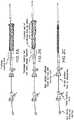
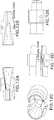
- FIG. 5Ashows a schematic perspective view of a Fontan-type prosthesis
- FIG. 5Bshows a side view schematic of such a prosthesis.
- Adjoining rings of the framework of the prosthesisare attached (e.g., by stitching) to a tubular fabric that preferably passes through the rings of the framework, wherein the framework is made, for example, of .014 inch diameter NiTi.
- the longitudinal dimension of each structural ringcan be different.
- region "A" of the prosthesiscan be comparatively stiff, wherein the rings can be attached to each other directly or via the fabric, wherein regions B, C, D, and E can have different, lower stiffnesses.
- FIG. 6Aillustrates a first embodiment of a prosthesis for a Fontan procedure.
- the bodyis similar to that of the prosthesis in FIG. 5 , but is made, for example, from .013 inch diameter Ni Ti wire.
- FIG. 6Billustrates a second embodiment that is also formed from the same wire, but the flange is formed at a steeper angle to create an increased flip, or displacement, of the distal flange when the prosthesis is deployed.
- the prosthesiscan include one or more (e.g., 2) fenestrations through the fabric in a central region thereof to permit leakage into the right atrium when the prosthesis spans from its distal end situated within the main pulmonary artery to the superior vena cava.
- the below chartillustrates suitable dimensions for the prosthesis illustrated in FIG.
- FIG. 7illustrates an animal model wherein two prostheses are installed as disclosed herein using the disclosed delivery system; one in a Glenn procedure (connecting the SVC to the MPA to supply blood from the superior vena cava (SVC) to the main pulmonary artery (MPA)), and one in a Fontan procedure (connecting the inferior vena cava (IVC) through the ventricle to the main pulmonary artery (MPA)), wherein the prosthesis includes fenestrations to permit leakage through the prosthesis into the ventricle.
- a Glenn procedureconnecting the SVC to the MPA to supply blood from the superior vena cava (SVC) to the main pulmonary artery (MPA)
- Fontan procedureconnecting the inferior vena cava (IVC) through the ventricle to the main pulmonary artery (MPA)
- the prosthesisincludes fenestrations to permit leakage through the prosthesis into the ventricle.
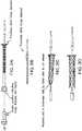
- FIG. 8Ashows the delivery system with the prosthesis (for the Glenn or Fontan procedure) mounted thereon.
- FIG. 8Bshows the core and distal tip advanced distally, and the distal flared end of the prosthesis deployed.
- FIG. 8Cshows a close up of the flared distal end of the prosthesis.
- FIG. 8Dshows the prosthesis mostly deployed, but the tether tensioned so as to keep the proximal end of the prosthesis held radially inwardly.
- FIGS. 9A and 9Bshow two different embodiments of a prosthesis as described above, FIG. 9C shows the prosthesis collapsed and within a sheath of the delivery system, whereas FIG. 9D shows the proximal ends of the delivery systems for each prosthesis.
- FIG. 9A and 9Bshow two different embodiments of a prosthesis as described above, FIG. 9C shows the prosthesis collapsed and within a sheath of the delivery system, whereas FIG. 9D shows the proximal ends of the delivery systems for
- the distal tipacts as a strain relief from a guidewire extending distally outwardly of a central guidewire lumen of the device. As such, while it is preferable to have the tip be relatively long, it is also useful to have it not be too long so as to prevent the delivery system from navigating a relatively narrow lumen when entering it obliquely.
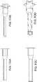
- FIGS. 10A-10Bshow side and isometric views of a prosthesis having a flanged distal end.
- FIGS. 10CA-10Dshow side and isometric views of a prosthesis having a flanged distal end as well as a flanged proximal end (upon prosthesis deployment).
- the illustrated prosthesesalso include a first section of relatively large diameter, such as near the flanged end, that transitions to a region of lower diameter by way of a transition region.
- the prosthesiscan also be of adjustable telescoping length. The inside diameter preferably remains substantially unchanged when the prosthesis is adjusted in length.
- FIGS. 11A-11Bshow a flanged prosthesis of adjustable length having two flanged ends attached to tubular structural regions, that are in turn structurally joined in a central region by an elastic member, such as a spring.
- a tubular fabric memberpreferably traverses the inside or the outside of the length of the prosthesis.
- the prosthesisis shown without such a tubular fabric member for illustrative purposes, and each end can be of a different diameter from the other.
- Such a prosthesiscan be useful, for example, for forming a shunt from the descending aorta to the main pulmonary artery to decompress the aorta.
- the lengthcan be adjusted of the prosthesis, and tension can be maintained on the prosthesis by way of the spring, helping the flanged ends to seat against the inner walls of the aorta and the MPA.
- FIGS. 12A-12Hillustrate aspects of a prosthesis loading tool in accordance with the disclosure.
- the loading toolincludes two halves, the inner faces of which are illustrated in FIGS. 12A and 12B .
- An interior channelincluding a first funnel portion necking down from a relatively large diameter to a relatively small diameter transitions into a second region of constant diameter, but wherein a step, or shoulder is present on the region of smaller diameter that effectively results in the funnel portion having a slightly smaller diameter than the region of constant diameter.
- the two halvesalign and mate with each other by way of a pair of protrusions on one half of the tool being received by a pair of indentations, or holes, on the other half of the tool.
- the distal end of the sheath that will cover the prosthesisis inserted into the end of the prosthesis having the portion of constant diameter until it abuts the shoulder.
- the central shaft of the delivery systempasses through the sheath and the funnel section.
- the prosthesis, loaded with the tether on its proximal end,is then advanced into the funnel and is necked down to fit inside the sheath, but surrounding the central shaft, or tubular core member, of the delivery system. Advancing the prosthesis into the funnel section helps effectuate the compression. After the prosthesis is loaded, the loading tool is simply removed.
- the delivery systemis advanced to a position where the prosthesis should be deployed.
- the distal tip and core of the guidewireare then advanced distally as well as the prosthesis, and the prosthesis flange is deployed thorough an opening in a wall of a vessel or other tissue wall.
- the flanged endthen urges against the inner wall of the vessel.
- a corresponding markercan be used on the proximal end of the delivery system to show at what point of relative advancement the flange has been deployed.
- the delivery systemis then pulled proximally slightly to seat the flange. When satisfied with seating, the user holds the inner shaft of the delivery system and pulls back on outer sheath to release the entire implant.
- the tethercan then be de-tensioned to open the proximal end of implant. Finally, the user can pull on one end of the tether to remove it from the implant, and the delivery system can be removed. However, if desired, prior to removal of the tether, the tether can be re-tensioned, causing the proximal end of the prosthesis to collapse radially inwardly, and the prosthesis can be withdrawn into the sheath of the delivery system, and removed.
Landscapes
- Health & Medical Sciences (AREA)
- Life Sciences & Earth Sciences (AREA)
- Engineering & Computer Science (AREA)
- Biomedical Technology (AREA)
- Veterinary Medicine (AREA)
- Heart & Thoracic Surgery (AREA)
- Animal Behavior & Ethology (AREA)
- General Health & Medical Sciences (AREA)
- Public Health (AREA)
- Surgery (AREA)
- Pulmonology (AREA)
- Cardiology (AREA)
- Vascular Medicine (AREA)
- Transplantation (AREA)
- Oral & Maxillofacial Surgery (AREA)
- Nuclear Medicine, Radiotherapy & Molecular Imaging (AREA)
- Molecular Biology (AREA)
- Gastroenterology & Hepatology (AREA)
- Medical Informatics (AREA)
- Anesthesiology (AREA)
- Biophysics (AREA)
- Hematology (AREA)
- Prostheses (AREA)
- Surgical Instruments (AREA)
Description
- The present disclosure relates to devices for transcatheter (i.e., performed through the lumen of a catheter) Glenn shunt and Fontan systems (transcatheter cavopulmonary bypass endograft prosthesis and delivery) for nonsurgical, percutaneous extra-anatomic bypass between two adjacent vessels.
- Children born with single ventricle physiology (SVP), a form of cyanotic congenital heart disease (CCHD), represent 7.7% of all congenital heart disease patients and have a birth incidence of approximately 4-8 per 10,000. In the United States, this represents approximately 2,000 children born each year. Currently, SVP infants undergo a series of staged surgical procedures. The first palliative procedure establishes a balance between systemic and pulmonary output while minimizing the overload on the single ventricle. The following palliative procedure is often cavopulmonary anastomosis through a bidirectional Glenn shunt or hemi-Fontan procedure to allow for passive pulmonary bloodflow. These are surgical procedures that are invasive and traumatic, requiring significant recuperation time and excessive burden on such a young patient.
US 2010/160847 describes a cardiovascular conduit system may comprise a connector. The connector may comprise a proximal end adapted to attach to a cardiovascular organ. The proximal end may comprise a first plurality of expandable members, and each member in the first plurality of expandable members may be deployable from a delivery position to a deployed position. The first plurality of expandable members may be dimensioned to deploy inside the cardiovascular organ to secure the connector to the cardiovascular organ. The connector may comprise a distal end adapted to attach to a conduit and an opening extending through the connector. Connectors for cardiovascular conduit systems may also include expandable stents. Connectors may be rotateably secured to a conduit, and the conduit may be reinforced. - The purpose and advantages of the present disclosure will be set forth in and become apparent from the description that follows. Additional advantages of the disclosed embodiments will be realized and attained by the methods and systems particularly pointed out in the written description hereof, as well as from the appended drawings.
- A transcatheter approach for obtaining the results of the surgical procedures described above can revolutionize the management of these children with congenital heart disease. As an alternative to the Norwood Procedure, Bi-directional Glenn operation and Fontan procedure, a nonsurgical transcatheter intervention can limit the burden of surgery for infants while also reducing cost. There is a considerable unmet need for a purpose-built cavopulmonary anastomosis device. To Applicant's knowledge no commercial alternatives exist for off-label medical use.
- To achieve these and other advantages and in accordance with the purpose of the disclosure, as embodied herein, in one aspect, the disclosure includes embodiments of a cavopulmonary self-expanding implant to permit an interventional cardiologist to create a shunt between the Superior Vena Cava (SVC) and the main pulmonary artery (MPA). The implant can provide an urgently needed option for children with congenital heart failure to avoid the burden of a three-stage surgery (so called palliative surgery), the burden of an additional heart transplantation after failure of the palliative surgeries, or of the lifelong medication intake after direct heart transplantation.
- In some implementations, a radially self-expanding endograft prosthesis is provided that includes (i) distal flange that is self-expanding and configured to flip generally perpendicularly with respect to a body of the prosthesis to help seat the prosthesis against a tissue wall, (ii) a distal segment extending proximally from the distal flange that has sufficient stiffness to maintain a puncture open that is formed through a vessel wall (iii) a compliant middle segment extending proximally from the distal segment, the middle segment being more compliant than the distal segment, and having independently movable undulating strut rings attached to a tubular fabric, the combined structure providing flexibility and compliance to allow for full patency while flexed, the segment being configured to accommodate up to a 90 degree bend, (iv) a proximal segment having a plurality of adjacent undulating strut rings that are connected to each other, the proximal segment being sufficiently stiff to seat within and urge against a vessel wall, and (v) a proximal end including a plurality of openings around the proximal end for accommodating a tether that is threaded through the openings to cause the prosthesis to collapse radially inwardly when tension is applied to the tether.
- In some implementations, a delivery system is provided including the prosthesis as set forth above, wherein the prosthesis is mounted on a longitudinal inner member and inside of a retractable sheath. Both ends of the tether that is routed through the prosthesis can extend proximally through and out of a proximal region of the delivery system. The delivery system can further include a first set of radiopaque markers near the distal end of the delivery system, and a second set of markers that are visible outside the patient during a procedure that indicates the relative position of the delivery system and prosthesis, wherein the first and second set of markers are maintained in registration with each other during the procedure. The first set of markers can be located on a distal atraumatic tip of the delivery system made of iron oxide to facilitate navigation under MRI or other imaging modality to position the delivery system accurately, and the second set of markers can indicate the relative longitudinal position of the portions of the delivery system. The markers can be configured to indicate when the distal flange of the prosthesis is suitably configured to pull against an inner face of the wall of an artery, such as main pulmonary artery.
- The prosthesis can further include a flared or bell-shaped proximal region to enhance apposition against the interior wall of a lumen. The prosthesis can further define at least one fenestration through a sidewall thereof to permit leakage of bodily fluid through the fenestration.
- In some implementations, a tubular prosthesis is provided having a first flanged end and a second flanged end, each flanged end being configured to urge against an inner surface of a first body lumen and a second body lumen when the prosthesis is mounted through openings formed into the walls of the first body lumen and second body lumen. The prosthesis can be adjusted in length. The prosthesis can include proximal and distal portions connected by a central elastic region such that the prosthesis can be stretched to cause the flanged ends of the prosthesis to pull against the lumens that the flanged ends are mounted into.
- It is to be understood that both the foregoing general description and the following detailed description are exemplary and are intended to provide further explanation of the embodiments disclosed herein.
- The accompanying drawings, which are incorporated in and constitute part of this specification, are included to illustrate and provide a further understanding of the method and system of the disclosure. Together with the description, the drawings serve to explain the principles of the disclosed embodiments.
- The foregoing and other objects, aspects, features, and advantages of exemplary embodiments will become more apparent and may be better understood by referring to the following description taken in conjunction with the accompanying drawings, in which:
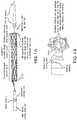
FIG. 1A depicts a view of a self-expanding prosthesis for performing a Glenn procedure disposed about a distal region of a delivery system for the prosthesis.FIG. 1B depicts a close-up view of a portion of the prosthesis depicted inFIG. 1A .FIG. 2A-FIG. 2C illustrate use of the loading tool ofFIG. 12 to load a prosthesis such as that ofFIG. 1A onto a delivery system.FIGS. 3A-FIG. 3B illustrate a prosthesis delivery system in its initial deployment position.FIG. 3C illustrates the prosthesis fully deployed but threaded with a retraction tether.FIG. 3D illustrates the prosthesis fully deployed with the retraction tether removed.FIG. 4A illustrates an exemplary prosthesis for a Glenn procedure, for example, in a deployed condition.FIG. 4B illustrates the same prosthesis being articulated to the right at its distal end.FIG. 4C illustrates the articulated prosthesis ofFIG. 4B to show the flared distal end.FIG. 4D shows a model of a Glenn shunt prosthesis in accordance with the disclosure being deployed in the main pulmonary artery (MPA) and the superior vena cava (SVC).FIG. 4E shows a scan of a fully deployed percutaneous cavopulmonary bypass endograft self-expanding prosthesis in a large porcine model used in a Glenn procedure.FIG. 5A is an isometric schematic view of an illustrative prosthesis for use in a Fontan procedure, andFIG. 5B is a plan view of such a prosthesis.FIG. 6A is a first illustrative embodiment of a prosthesis for use in a Fontan procedure, andFIG. 6B is a second illustrative embodiment of a prosthesis for use in a Fontan procedure.FIG. 7 is an image of prostheses deployed in Glenn and Fontan procedures in a test animal in accordance with the disclosure.FIG. 8A - FIG. 8E are illustrations of various aspects of a method of deploying a prosthesis in accordance with the disclosure.FIG. 9A - FIG. 9E are illustrations of further aspects of the illustrative prostheses and delivery systems in accordance with the disclosure.FIG. 10A , B -FIG. 10C , D are illustrations of two further embodiments of prostheses in accordance with the disclosure.FIGS. 11A-11B are illustrations of a further embodiment of a prosthesis in accordance with the disclosure.FIGS. 12A-12H are illustrations of a prosthesis loading tool in accordance with the disclosure.- Reference will now be made in detail to the present preferred embodiments of the disclosure, examples of which are illustrated in the accompanying drawings. The method that is not part of the invention and corresponding steps of the disclosed embodiments will be described in conjunction with the detailed description of the system. The exemplary embodiments illustrated herein can be used to perform Glenn and Fontan procedures, but percutaneously. It will be appreciated, however, that the disclosed embodiments, or variations thereof, can be used for a multitude of procedures involving the connection of blood vessels or other biological lumens to native or artificial structures.
- Embodiments of a disclosed TCBE (Transcatheter Cavopulmonary Bypass Endograft) represent a potential breakthrough for physicians and young patients who require a safe, less-burdensome, and effective alternative to open heart surgery: a percutaneous approach to heal congenital heart failure.
- In particular implementations, the underlying design of the TCBE is based on four components: (i) a distal segment, which is divided into a flange (consisting of a multi-pointed (e.g., six-pointed) star) and two to four rows of connected (e.g., by stitching) undulating wire segments; (ii) a middle segment, which includes longer non-connected undulating wire segments, (iii) and the largest, proximal, segment, which is useful for bridging and stabilization of the implant in the vessel. Depending on the size of the implant, it can be built as a "Glenn Shunt" (about 5 cm in length) or a "Fontan Shunt" (about 8 cm in length). These can be, for example, super elastic Nitinol-supported tubular polyester fabric implants that are delivered through a specially designed delivery system. Preferably, the prosthesis and delivery system are both MRI compatible. The illustrated TCBE embodiments can incorporate several useful features specifically developed for transcatheter cavopulmonary bypass.
- For purposes of illustration, and not limitation, as embodied herein and as illustrated in
FIG. 1 , a prosthesis is provided for transcatheter cavopulmonary bypass situated on a distal region of a delivery system. As can be seen, the device has a tubular stent-like structure formed from ring shaped segments that have an undulating "zigzag" pattern. A first, proximal end of the prosthesis has an undulating end defined by the proximal-most ring of the prosthesis. The distal end has a similar undulating end formed from a ring of undulating material, but the material is heat treated such that it "flips" from a first direction that is generally parallel to a central longitudinal axis of the prosthesis, and relaxes into a bent over flange having a tip that is generally perpendicular to the longitudinal axis of the prosthesis when permitted to expand. The flange can be oriented at any suitable angle with respect to the longitudinal axis, and is preferably perpendicular thereto, or forms a slightly acute angle with respect to the wall of the prosthesis (e.g., between 70 and 90 degrees). The flange is useful for pulling against the inside of a vessel or other tissue wall when the remaining prosthesis is advanced through an opening in such vessel or other tissue wall, preventing pull through, and permitting a facilitated anastomosis procedure generally, as well as for Glenn and Fontan procedures. - As can be seen, the proximal end of the prosthesis receives a tether therethrough that is routed through the windings of the undulating ring. The tethers are withdrawn proximally through a tubular member (e.g., a sheath) that also passes a core member therethrough that forms the core, or push rod of the delivery system. The core is slidably disposable with respect to the sheath. By advancing the core member with the prosthesis mounted thereto distally outwardly of the sheath, the prosthesis self-expands. However, if the tether is tensioned, it causes the proximal end of the prosthesis to collapse radially inwardly such that the prosthesis can be withdrawn into the sheath. While adjacent undulating rings of the prosthesis particularly near the distal end of the prosthesis can be connected to each other (e.g., by sewing), they can also be kept independent of one another, and be attached to an inner and/or outer tubular fabric layer. The rigidity of the prosthesis is selected and/or configured to provide a desired performance. Thus, the distal end is relatively rigid to maintain an opening in the wall of a vessel or other organ in an open state that the prosthesis traverses through by resisting the force of the vessel wall to want to "close" the hole in itself. The proximal region is less rigid and can accommodate increasing vessel curvature of the vessel that it is mounted in.
- The delivery system typically includes an atraumatic distal tip that can pass a guidewire therethrough, and may be provided with one or more radiopaque markers to facilitate visualization under fluoroscopy, for example. The distal end or end region of the sheath of the delivery system (that surrounds the prosthesis when loaded onto the delivery system) can also include a radiopaque marker.
FIGS. 2A-2D illustrate loading of the prosthesis on the core member of the delivery system using a clam shell like loading tool described in further detail below with respect toFIG. 12 .FIG. 2C illustrates the delivery system in a collapsed condition. The delivery system includes the aforementioned core member defining a guide wire lumen therethrough. The sheath is fitted over the core, and the tethers run between the components in the annular space between the core and sheath. As shown inFIG. 3A , the flared distal end of the prosthesis flips over from zero to 90 degrees as the sheath is advanced proximally. The proximal end of the prosthesis is held radially inwardly by the tether until tension of the tether is released. Tension can be reapplied to the tether to permit the prosthesis to be fully removable unless the tether is removed.FIG. 4a shows the disclosed prosthesis for a Glenn procedure. The distal region on the prosthesis is flexible to permit passage of the prosthesis through a curved vessel.FIG. 4D shows the distal flanged end of the prosthesis pulling against the inner wall of the main pulmonary artery (MPA), with the proximal end of the prosthesis extending into the superior vena cava in a Glenn procedure.FIG. 5A shows a schematic perspective view of a Fontan-type prosthesis, andFIG. 5B shows a side view schematic of such a prosthesis. Adjoining rings of the framework of the prosthesis are attached (e.g., by stitching) to a tubular fabric that preferably passes through the rings of the framework, wherein the framework is made, for example, of .014 inch diameter NiTi. The longitudinal dimension of each structural ring can be different. For example, region "A" of the prosthesis can be comparatively stiff, wherein the rings can be attached to each other directly or via the fabric, wherein regions B, C, D, and E can have different, lower stiffnesses.Figure 6A illustrates a first embodiment of a prosthesis for a Fontan procedure. The body is similar to that of the prosthesis inFIG. 5 , but is made, for example, from .013 inch diameter Ni Ti wire.FIG. 6B illustrates a second embodiment that is also formed from the same wire, but the flange is formed at a steeper angle to create an increased flip, or displacement, of the distal flange when the prosthesis is deployed. The prosthesis can include one or more (e.g., 2) fenestrations through the fabric in a central region thereof to permit leakage into the right atrium when the prosthesis spans from its distal end situated within the main pulmonary artery to the superior vena cava. The below chart illustrates suitable dimensions for the prosthesis illustrated inFIG. 5B .Fontan Structural Component Chart Section "A" Section "B" Section "C" Section "D" Section "E" Section "F" ID Diameter 12mm 12mm 12mm 20mm 20mm 12mm Zig Length 5mm 5mm 8mm 8mm 8mm 5mm Wite Size .014" .012" .012" 1.014" .014" .013" Zig connection connected unconnected connected connected connected connected FIG. 6B to provide enhanced wall apposition.FIG. 7 illustrates an animal model wherein two prostheses are installed as disclosed herein using the disclosed delivery system; one in a Glenn procedure (connecting the SVC to the MPA to supply blood from the superior vena cava (SVC) to the main pulmonary artery (MPA)), and one in a Fontan procedure (connecting the inferior vena cava (IVC) through the ventricle to the main pulmonary artery (MPA)), wherein the prosthesis includes fenestrations to permit leakage through the prosthesis into the ventricle.FIG. 8A shows the delivery system with the prosthesis (for the Glenn or Fontan procedure) mounted thereon.FIG. 8B shows the core and distal tip advanced distally, and the distal flared end of the prosthesis deployed.FIG. 8C shows a close up of the flared distal end of the prosthesis.FIG. 8D shows the prosthesis mostly deployed, but the tether tensioned so as to keep the proximal end of the prosthesis held radially inwardly.FIGS. 9A and 9B show two different embodiments of a prosthesis as described above,FIG. 9C shows the prosthesis collapsed and within a sheath of the delivery system, whereasFIG. 9D shows the proximal ends of the delivery systems for each prosthesis.FIG. 9E shows differing sizes of distal tips that can be used, depending on the application. The distal tip acts as a strain relief from a guidewire extending distally outwardly of a central guidewire lumen of the device. As such, while it is preferable to have the tip be relatively long, it is also useful to have it not be too long so as to prevent the delivery system from navigating a relatively narrow lumen when entering it obliquely.FIGS. 10A-10B show side and isometric views of a prosthesis having a flanged distal end.FIGS. 10CA-10D show side and isometric views of a prosthesis having a flanged distal end as well as a flanged proximal end (upon prosthesis deployment). The illustrated prostheses also include a first section of relatively large diameter, such as near the flanged end, that transitions to a region of lower diameter by way of a transition region. The prosthesis can also be of adjustable telescoping length. The inside diameter preferably remains substantially unchanged when the prosthesis is adjusted in length.FIGS. 11A-11B show a flanged prosthesis of adjustable length having two flanged ends attached to tubular structural regions, that are in turn structurally joined in a central region by an elastic member, such as a spring. A tubular fabric member preferably traverses the inside or the outside of the length of the prosthesis. The prosthesis is shown without such a tubular fabric member for illustrative purposes, and each end can be of a different diameter from the other. Such a prosthesis can be useful, for example, for forming a shunt from the descending aorta to the main pulmonary artery to decompress the aorta. The length can be adjusted of the prosthesis, and tension can be maintained on the prosthesis by way of the spring, helping the flanged ends to seat against the inner walls of the aorta and the MPA.FIGS. 12A-12H illustrate aspects of a prosthesis loading tool in accordance with the disclosure. As illustrated, the loading tool includes two halves, the inner faces of which are illustrated inFIGS. 12A and 12B . An interior channel including a first funnel portion necking down from a relatively large diameter to a relatively small diameter transitions into a second region of constant diameter, but wherein a step, or shoulder is present on the region of smaller diameter that effectively results in the funnel portion having a slightly smaller diameter than the region of constant diameter. As illustrated inFIGS. 12C-12E , the two halves align and mate with each other by way of a pair of protrusions on one half of the tool being received by a pair of indentations, or holes, on the other half of the tool. In use, the distal end of the sheath that will cover the prosthesis is inserted into the end of the prosthesis having the portion of constant diameter until it abuts the shoulder. In use, the central shaft of the delivery system passes through the sheath and the funnel section. The prosthesis, loaded with the tether on its proximal end, is then advanced into the funnel and is necked down to fit inside the sheath, but surrounding the central shaft, or tubular core member, of the delivery system. Advancing the prosthesis into the funnel section helps effectuate the compression. After the prosthesis is loaded, the loading tool is simply removed.- Generally, during deployment, the delivery system is advanced to a position where the prosthesis should be deployed. The distal tip and core of the guidewire are then advanced distally as well as the prosthesis, and the prosthesis flange is deployed thorough an opening in a wall of a vessel or other tissue wall. The flanged end then urges against the inner wall of the vessel. A corresponding marker can be used on the proximal end of the delivery system to show at what point of relative advancement the flange has been deployed. The delivery system is then pulled proximally slightly to seat the flange. When satisfied with seating, the user holds the inner shaft of the delivery system and pulls back on outer sheath to release the entire implant. The tether can then be de-tensioned to open the proximal end of implant. Finally, the user can pull on one end of the tether to remove it from the implant, and the delivery system can be removed. However, if desired, prior to removal of the tether, the tether can be re-tensioned, causing the proximal end of the prosthesis to collapse radially inwardly, and the prosthesis can be withdrawn into the sheath of the delivery system, and removed.
- The devices and methods disclosed herein can be used for other procedures in an as-is condition, or can be modified as needed to suit the particular procedure. In view of the many possible embodiments to which the principles of this disclosure may be applied, it should be recognized that the illustrated embodiments are only preferred examples of the disclosure and should not be taken as limiting the scope of the disclosure.
Claims (8)
- A radially self-expanding endograft prosthesis comprising:a distal flange that is self-expanding and configured to flip generally perpendicularly with respect to a body of the prosthesis to help seat the prosthesis against a tissue wall;a distal segment extending proximally from the distal flange that has sufficient stiffness to maintain a puncture open that is formed through a vessel wall;a compliant middle segment extending proximally from the distal segment, the middle segment being more compliant than the distal segment, and having independently movable undulating strut rings attached to a tubular fabric, the combined structure providing flexibility and compliance to allow for full patency while flexed, the segment being configured to accommodate up to a 90 degree bend;a proximal segment having a plurality of adjacent undulating strut rings that are connected to each other, the proximal segment being sufficiently stiff to seat within and urge against a vessel wall; anda proximal end including a plurality of openings around the proximal end for accommodating a tether that is threaded through the openings to cause the prosthesis to collapse radially inwardly when tension is applied to the tether.
- A delivery system including the prosthesis of Claim 1, wherein the prosthesis is mounted on a longitudinal inner member and inside of a retractable sheath.
- The delivery system of Claim 2, wherein both ends of the tether that is routed through the prosthesis extend proximally through and out of a proximal region of the delivery system.
- The delivery system of Claim 3, further comprising a first set of radiopaque markers near the distal end of the delivery system, and a second set of markers that are visible outside the patient during a procedure that indicates the relative position of the delivery system and prosthesis, wherein the first and second set of markers are maintained in registration with each other during the procedure.
- The delivery system of claim 4, wherein the first set of markers is located on a distal atraumatic tip of the delivery system made of iron oxide to facilitate navigation under MRI or other imaging modality to position the delivery system accurately, and wherein the second set of markers indicates the relative longitudinal position of the portions of the delivery system.
- The delivery system of claim 4, wherein the markers are configured to indicate when the distal flange of the prosthesis is suitably configured to pull against an inner face of the wall of a lumen.
- The prosthesis of Claim 1, further including a flared or bell-shaped proximal region to enhance apposition against the interior wall of a lumen.
- The prosthesis of Claim 1, further defining at least one fenestration through a sidewall thereof to permit leakage of bodily fluid through the fenestration.
Applications Claiming Priority (3)
| Application Number | Priority Date | Filing Date | Title |
|---|---|---|---|
| US201562219118P | 2015-09-15 | 2015-09-15 | |
| US201662363716P | 2016-07-18 | 2016-07-18 | |
| PCT/US2016/052005WO2017049003A1 (en) | 2015-09-15 | 2016-09-15 | Devices and methods for effectuating percutaneous glenn and fontan procedures |
Publications (3)
| Publication Number | Publication Date |
|---|---|
| EP3349687A1 EP3349687A1 (en) | 2018-07-25 |
| EP3349687A4 EP3349687A4 (en) | 2019-06-26 |
| EP3349687B1true EP3349687B1 (en) | 2020-09-09 |
Family
ID=58257893
Family Applications (1)
| Application Number | Title | Priority Date | Filing Date |
|---|---|---|---|
| EP16847336.1AActiveEP3349687B1 (en) | 2015-09-15 | 2016-09-15 | Devices for effectuating percutaneous glenn and fontan procedures |
Country Status (4)
| Country | Link |
|---|---|
| US (4) | US10426482B2 (en) |
| EP (1) | EP3349687B1 (en) |
| JP (1) | JP6869967B2 (en) |
| WO (1) | WO2017049003A1 (en) |
Families Citing this family (15)
| Publication number | Priority date | Publication date | Assignee | Title |
|---|---|---|---|---|
| EP3349687B1 (en) | 2015-09-15 | 2020-09-09 | THE UNITED STATES OF AMERICA, represented by the S | Devices for effectuating percutaneous glenn and fontan procedures |
| JP7249332B2 (en)* | 2017-09-01 | 2023-03-30 | トランスミューラル システムズ エルエルシー | Percutaneous shunt device and related methods |
| JP7570320B2 (en)* | 2018-09-19 | 2024-10-21 | エヌエックスティー バイオメディカル,エルエルシー | Methods and techniques for forming connections and shunts between cavities and vessels in biological structures - Patents.com |
| US20200101270A1 (en)* | 2018-09-24 | 2020-04-02 | Michael Warren Sutherland | Pulmonary arterial compliance enhancement and control device |
| EP3920855B1 (en) | 2019-02-07 | 2025-07-23 | NXT Biomedical, LLC | Rivet shunt |
| WO2021025905A1 (en)* | 2019-08-06 | 2021-02-11 | Edwards Lifesciences Corporation | External cardiac bypass shunting |
| EP4017384A1 (en) | 2019-08-22 | 2022-06-29 | Edwards Lifesciences Corporation | Puncture needles |
| US12059540B2 (en) | 2019-09-13 | 2024-08-13 | Drexel University | Right ventricle-pulmonary artery/left ventricle-aorta conduit |
| US12390370B2 (en)* | 2019-11-01 | 2025-08-19 | Aventamed Designated Activity Company | Tympanostomy tube |
| CR20220218A (en) | 2019-11-14 | 2022-08-22 | Edwards Lifesciences Corp | Transcatheter medical implant delivery |
| US12318563B1 (en) | 2021-02-02 | 2025-06-03 | Taurus Vascular, Inc. | Methods and systems for transcaval treatment of aneurysms |
| US12310837B1 (en) | 2024-01-22 | 2025-05-27 | Taurus Vascular, Inc. | Methods and systems for transcaval treatment of aneurysms |
| WO2022187560A1 (en)* | 2021-03-03 | 2022-09-09 | BALCOM, Alexis | Percutaneous shunt devices and related methods |
| KR102592959B1 (en)* | 2021-06-03 | 2023-10-23 | 재단법인 아산사회복지재단 | Catheter apparatus for photodynamic therapy |
| WO2024155994A1 (en) | 2023-01-20 | 2024-07-25 | Texas Medical Center | Methods and systems for transcaval treatment of aneurysms |
Family Cites Families (155)
| Publication number | Priority date | Publication date | Assignee | Title |
|---|---|---|---|---|
| CA1069652A (en) | 1976-01-09 | 1980-01-15 | Alain F. Carpentier | Supported bioprosthetic heart valve with compliant orifice ring |
| AR221872A1 (en) | 1979-03-16 | 1981-03-31 | Liotta Domingo S | IMPROVEMENTS IN IMPANTABLE HEART VALVES |
| IT1208326B (en) | 1984-03-16 | 1989-06-12 | Sorin Biomedica Spa | CARDIAC VALVE PROSTHESIS PROVIDED WITH VALVES OF ORGANIC FABRIC |
| CH672247A5 (en) | 1986-03-06 | 1989-11-15 | Mo Vysshee Tekhnicheskoe Uchil | |
| US5411552A (en) | 1990-05-18 | 1995-05-02 | Andersen; Henning R. | Valve prothesis for implantation in the body and a catheter for implanting such valve prothesis |
| BR9205978A (en) | 1991-05-08 | 1994-07-26 | Nika Health Products Ltd | Process and apparatus for the production of a heart valve prosthesis |
| US5449384A (en) | 1992-09-28 | 1995-09-12 | Medtronic, Inc. | Dynamic annulus heart valve employing preserved porcine valve leaflets |
| US5639278A (en)* | 1993-10-21 | 1997-06-17 | Corvita Corporation | Expandable supportive bifurcated endoluminal grafts |
| EP0754012B1 (en) | 1995-02-07 | 2002-10-16 | C.R. Bard, Inc. | Telescoping serial elastic band ligator |
| WO1996036297A1 (en)* | 1995-05-19 | 1996-11-21 | Kanji Inoue | Transplantation instrument, method of bending same and method of transplanting same |
| ATE372745T1 (en)* | 1995-12-14 | 2007-09-15 | Gore Enterprise Holdings Inc | Kink-resistant Stent Graft |
| US5861028A (en) | 1996-09-09 | 1999-01-19 | Shelhigh Inc | Natural tissue heart valve and stent prosthesis and method for making the same |
| US5749921A (en)* | 1996-02-20 | 1998-05-12 | Medtronic, Inc. | Apparatus and methods for compression of endoluminal prostheses |
| US6090136A (en)* | 1996-07-29 | 2000-07-18 | Radiance Medical Systems, Inc. | Self expandable tubular support |
| EP0850607A1 (en) | 1996-12-31 | 1998-07-01 | Cordis Corporation | Valve prosthesis for implantation in body channels |
| US5928281A (en) | 1997-03-27 | 1999-07-27 | Baxter International Inc. | Tissue heart valves |
| US5895410A (en) | 1997-09-12 | 1999-04-20 | B. Braun Medical, Inc. | Introducer for an expandable vascular occlusion device |
| US7491232B2 (en) | 1998-09-18 | 2009-02-17 | Aptus Endosystems, Inc. | Catheter-based fastener implantation apparatus and methods with implantation force resolution |
| US6106510A (en) | 1998-05-28 | 2000-08-22 | Medtronic, Inc. | Extruded guide catheter shaft with bump extrusion soft distal segment |
| JP2002524196A (en) | 1998-09-10 | 2002-08-06 | パーカーディア,インコーポレイティド | Transmyocardial shunt for left ventricular revascularization and its mounting mechanism |
| WO2000016701A1 (en) | 1998-09-18 | 2000-03-30 | United States Surgical Corporation | Endovascular fastener applicator |
| US6059769A (en) | 1998-10-02 | 2000-05-09 | Medtronic, Inc. | Medical catheter with grooved soft distal segment |
| US6152937A (en) | 1998-11-06 | 2000-11-28 | St. Jude Medical Cardiovascular Group, Inc. | Medical graft connector and methods of making and installing same |
| US6059824A (en)* | 1998-12-23 | 2000-05-09 | Taheri; Syde A. | Mated main and collateral stent and method for treatment of arterial disease |
| US6736845B2 (en) | 1999-01-26 | 2004-05-18 | Edwards Lifesciences Corporation | Holder for flexible heart valve |
| US6364905B1 (en) | 1999-01-27 | 2002-04-02 | Sulzer Carbomedics Inc. | Tri-composite, full root, stentless valve |
| US6248122B1 (en) | 1999-02-26 | 2001-06-19 | Vascular Architects, Inc. | Catheter with controlled release endoluminal prosthesis |
| CA2372149A1 (en)* | 1999-05-03 | 2000-11-09 | Dean F. Carson | Methods and devices for placing a conduit in fluid communication with a target vessel |
| US6790229B1 (en) | 1999-05-25 | 2004-09-14 | Eric Berreklouw | Fixing device, in particular for fixing to vascular wall tissue |
| US6346116B1 (en) | 1999-08-03 | 2002-02-12 | Medtronic Ave, Inc. | Distal protection device |
| SE515231C2 (en)* | 1999-10-13 | 2001-07-02 | Jan Otto Solem | Covered stent and way to manufacture the same |
| US20070043435A1 (en) | 1999-11-17 | 2007-02-22 | Jacques Seguin | Non-cylindrical prosthetic valve system for transluminal delivery |
| US7195641B2 (en) | 1999-11-19 | 2007-03-27 | Advanced Bio Prosthetic Surfaces, Ltd. | Valvular prostheses having metal or pseudometallic construction and methods of manufacture |
| US6458153B1 (en) | 1999-12-31 | 2002-10-01 | Abps Venture One, Ltd. | Endoluminal cardiac and venous valve prostheses and methods of manufacture and delivery thereof |
| IL153753A0 (en) | 2002-12-30 | 2003-07-06 | Neovasc Medical Ltd | Varying-diameter vascular implant and balloon |
| US6953476B1 (en) | 2000-03-27 | 2005-10-11 | Neovasc Medical Ltd. | Device and method for treating ischemic heart disease |
| US6454799B1 (en) | 2000-04-06 | 2002-09-24 | Edwards Lifesciences Corporation | Minimally-invasive heart valves and methods of use |
| US6602271B2 (en) | 2000-05-24 | 2003-08-05 | Medtronic Ave, Inc. | Collapsible blood filter with optimal braid geometry |
| US7510572B2 (en) | 2000-09-12 | 2009-03-31 | Shlomo Gabbay | Implantation system for delivery of a heart valve prosthesis |
| US6733525B2 (en) | 2001-03-23 | 2004-05-11 | Edwards Lifesciences Corporation | Rolled minimally-invasive heart valves and methods of use |
| US7374571B2 (en) | 2001-03-23 | 2008-05-20 | Edwards Lifesciences Corporation | Rolled minimally-invasive heart valves and methods of manufacture |
| US7044958B2 (en) | 2001-04-03 | 2006-05-16 | Medtronic Vascular, Inc. | Temporary device for capturing embolic material |
| US6818006B2 (en) | 2001-04-03 | 2004-11-16 | Medtronic Vascular, Inc. | Temporary intraluminal filter guidewire |
| US6866677B2 (en) | 2001-04-03 | 2005-03-15 | Medtronic Ave, Inc. | Temporary intraluminal filter guidewire and methods of use |
| US6911036B2 (en) | 2001-04-03 | 2005-06-28 | Medtronic Vascular, Inc. | Guidewire apparatus for temporary distal embolic protection |
| FR2826863B1 (en) | 2001-07-04 | 2003-09-26 | Jacques Seguin | ASSEMBLY FOR PLACING A PROSTHETIC VALVE IN A BODY CONDUIT |
| US20030065386A1 (en) | 2001-09-28 | 2003-04-03 | Weadock Kevin Shaun | Radially expandable endoprosthesis device with two-stage deployment |
| CA2462509A1 (en) | 2001-10-04 | 2003-04-10 | Neovasc Medical Ltd. | Flow reducing implant |
| US20050070992A1 (en) | 2001-11-28 | 2005-03-31 | Aptus Endosystems, Inc. | Prosthesis systems and methods sized and configured for the receipt and retention of fasteners |
| US20050177180A1 (en) | 2001-11-28 | 2005-08-11 | Aptus Endosystems, Inc. | Devices, systems, and methods for supporting tissue and/or structures within a hollow body organ |
| US7147657B2 (en) | 2003-10-23 | 2006-12-12 | Aptus Endosystems, Inc. | Prosthesis delivery systems and methods |
| AU2002353807B2 (en) | 2001-11-28 | 2008-08-14 | Aptus Endosystems, Inc. | Endovascular aneurysm repair system |
| US7137993B2 (en)* | 2001-12-03 | 2006-11-21 | Xtent, Inc. | Apparatus and methods for delivery of multiple distributed stents |
| US7105021B2 (en)* | 2002-04-25 | 2006-09-12 | Scimed Life Systems, Inc. | Implantable textile prostheses having PTFE cold drawn yarns |
| WO2004014257A1 (en) | 2002-08-08 | 2004-02-19 | Neovasc Medical Ltd. | Geometric flow regulator |
| WO2004014474A1 (en) | 2002-08-08 | 2004-02-19 | Neovasc Medical Ltd. | Flow reducing implant |
| US8075585B2 (en) | 2002-08-29 | 2011-12-13 | Stryker Corporation | Device and method for treatment of a vascular defect |
| US8518096B2 (en) | 2002-09-03 | 2013-08-27 | Lifeshield Sciences Llc | Elephant trunk thoracic endograft and delivery system |
| US7404824B1 (en) | 2002-11-15 | 2008-07-29 | Advanced Cardiovascular Systems, Inc. | Valve aptation assist device |
| US7189259B2 (en) | 2002-11-26 | 2007-03-13 | Clemson University | Tissue material and process for bioprosthesis |
| US7399315B2 (en) | 2003-03-18 | 2008-07-15 | Edwards Lifescience Corporation | Minimally-invasive heart valve with cusp positioners |
| US7294135B2 (en) | 2003-03-20 | 2007-11-13 | Medtronic Vascular, Inc | Control handle for intraluminal devices |
| US20050049675A1 (en) | 2003-03-28 | 2005-03-03 | Board Of Regents, The University Of Texas System | Medical devices and related methods |
| JP2004298472A (en)* | 2003-03-31 | 2004-10-28 | Clinical Supply:Kk | Stent |
| US7998188B2 (en) | 2003-04-28 | 2011-08-16 | Kips Bay Medical, Inc. | Compliant blood vessel graft |
| US7316706B2 (en) | 2003-06-20 | 2008-01-08 | Medtronic Vascular, Inc. | Tensioning device, system, and method for treating mitral valve regurgitation |
| US7201772B2 (en) | 2003-07-08 | 2007-04-10 | Ventor Technologies, Ltd. | Fluid flow prosthetic device |
| US7160322B2 (en) | 2003-08-13 | 2007-01-09 | Shlomo Gabbay | Implantable cardiac prosthesis for mitigating prolapse of a heart valve |
| US7425219B2 (en) | 2003-10-10 | 2008-09-16 | Arshad Quadri | System and method for endoluminal grafting of bifurcated and branched vessels |
| EP1689329A2 (en) | 2003-11-12 | 2006-08-16 | Medtronic Vascular, Inc. | Cardiac valve annulus reduction system |
| US7955384B2 (en) | 2003-11-12 | 2011-06-07 | Medtronic Vascular, Inc. | Coronary sinus approach for repair of mitral valve regurgitation |
| US7716801B2 (en) | 2003-11-24 | 2010-05-18 | Medtronic Vascular, Inc. | Low-profile distal protection device |
| JP2005178627A (en) | 2003-12-19 | 2005-07-07 | Toyota Motor Corp | Integrated control system for vehicles |
| US7445631B2 (en) | 2003-12-23 | 2008-11-04 | Sadra Medical, Inc. | Methods and apparatus for endovascularly replacing a patient's heart valve |
| US7959666B2 (en) | 2003-12-23 | 2011-06-14 | Sadra Medical, Inc. | Methods and apparatus for endovascularly replacing a heart valve |
| CA2556077C (en) | 2004-02-05 | 2012-05-01 | Children's Medical Center Corporation | Transcatheter delivery of a replacement heart valve |
| US9039724B2 (en) | 2004-03-19 | 2015-05-26 | Aga Medical Corporation | Device for occluding vascular defects |
| CA2563426C (en) | 2004-05-05 | 2013-12-24 | Direct Flow Medical, Inc. | Unstented heart valve with formed in place support structure |
| US7842069B2 (en) | 2004-05-07 | 2010-11-30 | Nmt Medical, Inc. | Inflatable occluder |
| US9706997B2 (en)* | 2004-08-27 | 2017-07-18 | Rox Medical, Inc. | Device and method for establishing an artificial arterio-venous fistula |
| US20060074480A1 (en)* | 2004-09-01 | 2006-04-06 | Pst, Llc | Stent and method for manufacturing the stent |
| FR2874813B1 (en) | 2004-09-07 | 2007-06-22 | Perouse Soc Par Actions Simpli | VALVULAR PROSTHESIS |
| US20060085012A1 (en) | 2004-09-28 | 2006-04-20 | Medtronic Vascular, Inc. | Torquing device delivered over a guidewire to rotate a medical fastener |
| US7682352B2 (en) | 2004-09-28 | 2010-03-23 | Medtronic Vascular, Inc. | Catheter with curved distal section having reinforcing strip and method of making same |
| US20100106171A1 (en) | 2005-05-06 | 2010-04-29 | Johns Hopkins University | Transcaval mesenteric venous anastomosis and access system |
| US7914569B2 (en) | 2005-05-13 | 2011-03-29 | Medtronics Corevalve Llc | Heart valve prosthesis and methods of manufacture and use |
| US20070067029A1 (en) | 2005-09-16 | 2007-03-22 | Shlomo Gabbay | Support apparatus to facilitate implantation of cardiac prosthesis |
| DE102005052628B4 (en) | 2005-11-04 | 2014-06-05 | Jenavalve Technology Inc. | Self-expanding, flexible wire mesh with integrated valvular prosthesis for the transvascular heart valve replacement and a system with such a device and a delivery catheter |
| CA2881760C (en) | 2005-11-10 | 2017-06-13 | Arshad Quadri | Balloon-expandable, self-expanding, vascular prosthesis connecting stent |
| EP1991168B1 (en) | 2006-02-16 | 2016-01-27 | Transcatheter Technologies GmbH | Minimally invasive heart valve replacement |
| JP5102279B2 (en) | 2006-03-10 | 2012-12-19 | メドトロニック,インコーポレイテッド | Artificial valve introducer, method for producing the same and method for using the same |
| US7699892B2 (en) | 2006-04-12 | 2010-04-20 | Medtronic Vascular, Inc. | Minimally invasive procedure for implanting an annuloplasty device |
| US8454683B2 (en) | 2006-04-12 | 2013-06-04 | Medtronic Vascular, Inc. | Annuloplasty device having a helical anchor and methods for its use |
| US7442207B2 (en) | 2006-04-21 | 2008-10-28 | Medtronic Vascular, Inc. | Device, system, and method for treating cardiac valve regurgitation |
| JP2009535128A (en) | 2006-04-29 | 2009-10-01 | アーバー・サージカル・テクノロジーズ・インコーポレイテッド | Multi-part prosthetic heart valve assembly and apparatus and method for delivering the same |
| US20070293942A1 (en) | 2006-06-16 | 2007-12-20 | Daryush Mirzaee | Prosthetic valve and deployment method |
| WO2008013915A2 (en) | 2006-07-28 | 2008-01-31 | Arshad Quadri | Percutaneous valve prosthesis and system and method for implanting same |
| US8876894B2 (en) | 2006-09-19 | 2014-11-04 | Medtronic Ventor Technologies Ltd. | Leaflet-sensitive valve fixation member |
| US8388680B2 (en) | 2006-10-18 | 2013-03-05 | Guided Delivery Systems, Inc. | Methods and devices for catheter advancement and delivery of substances therethrough |
| EP2097012A4 (en)* | 2006-11-07 | 2012-08-15 | David Stephen Celermajer | Devices and methods for the treatment of heart failure |
| ES2708789T3 (en) | 2006-12-19 | 2019-04-11 | St Jude Medical | Method for manufacturing a prosthetic heart valve that includes a structure of endoprostheses and tissue leaflets |
| US8070802B2 (en) | 2007-02-23 | 2011-12-06 | The Trustees Of The University Of Pennsylvania | Mitral valve system |
| US7753949B2 (en) | 2007-02-23 | 2010-07-13 | The Trustees Of The University Of Pennsylvania | Valve prosthesis systems and methods |
| JP5261725B2 (en)* | 2007-03-06 | 2013-08-14 | ウィリアム・エイ・クック・オーストラリア・プロプライエタリー・リミテッド | Intravascular placement device |
| US7806917B2 (en) | 2007-04-17 | 2010-10-05 | Medtronic Vascular, Inc. | Stent graft fixation system and method |
| WO2009045334A1 (en) | 2007-09-28 | 2009-04-09 | St. Jude Medical, Inc. | Collapsible/expandable prosthetic heart valves with native calcified leaflet retention features |
| US8992593B2 (en) | 2007-12-26 | 2015-03-31 | Cook Medical Technologies Llc | Apparatus and methods for deployment of a modular stent-graft system |
| US7815673B2 (en) | 2008-04-01 | 2010-10-19 | Medtronic Vascular, Inc. | Double-walled stent system |
| WO2009132187A1 (en) | 2008-04-23 | 2009-10-29 | Medtronic, Inc. | Stented heart valve devices |
| US20090270976A1 (en) | 2008-04-24 | 2009-10-29 | Medtronic Vascular, Inc. | Stent Graft Fixation System and Method of Use |
| US7972370B2 (en) | 2008-04-24 | 2011-07-05 | Medtronic Vascular, Inc. | Stent graft system and method of use |
| US8323337B2 (en) | 2008-06-05 | 2012-12-04 | Medtronic, Inc. | Connection systems for two piece prosthetic heart valve assemblies and methods for making and using them |
| CN102292053A (en) | 2008-09-29 | 2011-12-21 | 卡迪尔克阀门技术公司 | Heart valve |
| WO2010040009A1 (en) | 2008-10-01 | 2010-04-08 | Cardiaq Valve Technologies, Inc. | Delivery system for vascular implant |
| US8986361B2 (en) | 2008-10-17 | 2015-03-24 | Medtronic Corevalve, Inc. | Delivery system for deployment of medical devices |
| US8905961B2 (en) | 2008-12-19 | 2014-12-09 | St. Jude Medical, Inc. | Systems, apparatuses, and methods for cardiovascular conduits and connectors |
| US8308798B2 (en) | 2008-12-19 | 2012-11-13 | Edwards Lifesciences Corporation | Quick-connect prosthetic heart valve and methods |
| US20100174363A1 (en) | 2009-01-07 | 2010-07-08 | Endovalve, Inc. | One Piece Prosthetic Valve Support Structure and Related Assemblies |
| US8998982B2 (en) | 2009-01-12 | 2015-04-07 | Valve Medical Ltd. | Method and apparatus for fine adjustment of a percutaneous valve structure |
| US9402720B2 (en) | 2009-01-12 | 2016-08-02 | Valve Medical Ltd. | Modular percutaneous valve structure and delivery method |
| US9681950B2 (en) | 2009-01-12 | 2017-06-20 | Valve Medical Ltd. | System and method for placing a percutaneous valve device |
| US20100217382A1 (en) | 2009-02-25 | 2010-08-26 | Edwards Lifesciences | Mitral valve replacement with atrial anchoring |
| WO2010106438A2 (en) | 2009-03-17 | 2010-09-23 | Biomedxl | Heart valve prosthesis with collapsible valve and method of delivery thereof |
| EP3081195B1 (en) | 2009-04-10 | 2018-10-03 | Lon Sutherland Annest | An implantable scaffolding containing an orifice for use with a prosthetic or bio-prosthetic valve |
| CA2961053C (en) | 2009-04-15 | 2019-04-30 | Edwards Lifesciences Cardiaq Llc | Vascular implant and delivery system |
| EP2421468B1 (en) | 2009-04-20 | 2016-12-07 | Rox Medical, Inc. | Device for establishing an artificial arterio-venous fistula |
| FR2947716B1 (en) | 2009-07-10 | 2011-09-02 | Cormove | IMPLANT IMPLANT IMPROVED |
| US9730790B2 (en) | 2009-09-29 | 2017-08-15 | Edwards Lifesciences Cardiaq Llc | Replacement valve and method |
| US8652203B2 (en) | 2010-09-23 | 2014-02-18 | Cardiaq Valve Technologies, Inc. | Replacement heart valves, delivery devices and methods |
| US8449599B2 (en) | 2009-12-04 | 2013-05-28 | Edwards Lifesciences Corporation | Prosthetic valve for replacing mitral valve |
| EP3300695B1 (en) | 2009-12-08 | 2023-05-24 | Avalon Medical Ltd. | Device and system for transcatheter mitral valve replacement |
| CN102113921A (en) | 2009-12-30 | 2011-07-06 | 微创医疗器械(上海)有限公司 | Intervention-type heart valve |
| US9504562B2 (en) | 2010-01-12 | 2016-11-29 | Valve Medical Ltd. | Self-assembling modular percutaneous valve and methods of folding, assembly and delivery |
| US8579964B2 (en) | 2010-05-05 | 2013-11-12 | Neovasc Inc. | Transcatheter mitral valve prosthesis |
| WO2011163275A2 (en) | 2010-06-21 | 2011-12-29 | Cardiaq Valve Technologies, Inc. | Replacement heart valve |
| RU100718U1 (en) | 2010-07-08 | 2010-12-27 | Учреждение Российской академии медицинских наук Научный центр сердечно-сосудистой хирургии имени А.Н. Бакулева РАМН | HEART VALVE BIOPROTHESIS |
| US9132009B2 (en) | 2010-07-21 | 2015-09-15 | Mitraltech Ltd. | Guide wires with commissural anchors to advance a prosthetic valve |
| WO2012018917A1 (en)* | 2010-08-03 | 2012-02-09 | World Heart Corporation | Conformal cannula device and related methods |
| US9463269B2 (en) | 2010-09-10 | 2016-10-11 | W. L. Gore & Associates, Inc. | Anastomotic devices and methods |
| US20120078360A1 (en) | 2010-09-23 | 2012-03-29 | Nasser Rafiee | Prosthetic devices, systems and methods for replacing heart valves |
| US9579193B2 (en) | 2010-09-23 | 2017-02-28 | Transmural Systems Llc | Methods and systems for delivering prostheses using rail techniques |
| WO2012061809A2 (en) | 2010-11-06 | 2012-05-10 | Mehr Medical Llc | Methods and systems for delivering prostheses using rail techniques |
| US10321998B2 (en) | 2010-09-23 | 2019-06-18 | Transmural Systems Llc | Methods and systems for delivering prostheses using rail techniques |
| WO2012100059A1 (en)* | 2011-01-19 | 2012-07-26 | Endologix, Inc. | Methods and systems for treating aneurysms |
| CN103502279B (en) | 2011-04-26 | 2015-07-22 | 3M创新有限公司 | Pressure-sensitive adhesives with mixed photocrosslinking system |
| EP4289398A3 (en)* | 2011-08-11 | 2024-03-13 | Tendyne Holdings, Inc. | Improvements for prosthetic valves and related inventions |
| US9549817B2 (en) | 2011-09-22 | 2017-01-24 | Transmural Systems Llc | Devices, systems and methods for repairing lumenal systems |
| WO2013131069A1 (en) | 2012-03-02 | 2013-09-06 | Mehr Medical Llc | Prostheses |
| US20130158673A1 (en) | 2011-12-15 | 2013-06-20 | Cook Medical Technologies Llc | Anti-Leakage Prosthesis |
| KR101501614B1 (en) | 2012-03-29 | 2015-03-11 | 연세대학교 산학협력단 | Anastomosis stent |
| EP2861182B1 (en)* | 2012-06-15 | 2019-02-20 | Phraxis Inc. | Arterial and venous anchor devices forming an anastomotic connector |
| EP2967867B1 (en)* | 2013-03-15 | 2024-05-01 | Corvia Medical, Inc. | Devices for retrievable intra-atrial implants |
| WO2015148821A1 (en) | 2014-03-27 | 2015-10-01 | Nasser Rafiee | Devices and methods for closure of transvascular or transcameral access ports |
| EP3349687B1 (en)* | 2015-09-15 | 2020-09-09 | THE UNITED STATES OF AMERICA, represented by the S | Devices for effectuating percutaneous glenn and fontan procedures |
| JP7249332B2 (en) | 2017-09-01 | 2023-03-30 | トランスミューラル システムズ エルエルシー | Percutaneous shunt device and related methods |
- 2016
- 2016-09-15EPEP16847336.1Apatent/EP3349687B1/enactiveActive
- 2016-09-15USUS15/267,075patent/US10426482B2/enactiveActive
- 2016-09-15WOPCT/US2016/052005patent/WO2017049003A1/ennot_activeCeased
- 2016-09-15JPJP2018514884Apatent/JP6869967B2/enactiveActive
- 2019
- 2019-04-30USUS16/399,670patent/US11179156B2/enactiveActive
- 2021
- 2021-08-31USUS17/462,190patent/US11871928B2/enactiveActive
- 2024
- 2024-01-16USUS18/413,185patent/US20240268828A1/enactivePending
Non-Patent Citations (1)
| Title |
|---|
| None* |
Also Published As
| Publication number | Publication date |
|---|---|
| EP3349687A4 (en) | 2019-06-26 |
| JP6869967B2 (en) | 2021-05-12 |
| WO2017049003A1 (en) | 2017-03-23 |
| US11871928B2 (en) | 2024-01-16 |
| US20220125430A1 (en) | 2022-04-28 |
| US11179156B2 (en) | 2021-11-23 |
| US20240268828A1 (en) | 2024-08-15 |
| US20190321043A1 (en) | 2019-10-24 |
| US20170071722A1 (en) | 2017-03-16 |
| EP3349687A1 (en) | 2018-07-25 |
| US10426482B2 (en) | 2019-10-01 |
| JP2018528009A (en) | 2018-09-27 |
Similar Documents
| Publication | Publication Date | Title |
|---|---|---|
| EP3349687B1 (en) | Devices for effectuating percutaneous glenn and fontan procedures | |
| JP7191339B2 (en) | Improved embolic protection device and method | |
| US10307241B2 (en) | Embolic protection devices and methods of use | |
| JP5106537B2 (en) | Delivery tool for transdermal delivery of prostheses | |
| CA2836422C (en) | Inversion delivery device and method for a prosthesis | |
| US9579182B2 (en) | Method for delivery of an embolic protection unit | |
| US12376956B2 (en) | Percutaneous shunt devices and related methods | |
| CN102917669A (en) | Transcatheter delivery system and method with controlled expansion and contraction of prosthetic heart vavle | |
| AU2013270507A1 (en) | Delivery tool for percutaneous delivery of a prosthesis and related methods | |
| EP4294322A1 (en) | Methods and systems for placing embolic filters in an aortic arch | |
| WO2024158626A1 (en) | Implant delivery and delivery system retrieval | |
| HK1261974B (en) | Inversion delivery device for a prosthesis | |
| HK1261974A1 (en) | Inversion delivery device for a prosthesis | |
| HK1220351B (en) | Embolic protection devices |
Legal Events
| Date | Code | Title | Description |
|---|---|---|---|
| STAA | Information on the status of an ep patent application or granted ep patent | Free format text:STATUS: THE INTERNATIONAL PUBLICATION HAS BEEN MADE | |
| PUAI | Public reference made under article 153(3) epc to a published international application that has entered the european phase | Free format text:ORIGINAL CODE: 0009012 | |
| STAA | Information on the status of an ep patent application or granted ep patent | Free format text:STATUS: REQUEST FOR EXAMINATION WAS MADE | |
| 17P | Request for examination filed | Effective date:20180403 | |
| AK | Designated contracting states | Kind code of ref document:A1 Designated state(s):AL AT BE BG CH CY CZ DE DK EE ES FI FR GB GR HR HU IE IS IT LI LT LU LV MC MK MT NL NO PL PT RO RS SE SI SK SM TR | |
| AX | Request for extension of the european patent | Extension state:BA ME | |
| DAV | Request for validation of the european patent (deleted) | ||
| DAX | Request for extension of the european patent (deleted) | ||
| A4 | Supplementary search report drawn up and despatched | Effective date:20190524 | |
| RIC1 | Information provided on ipc code assigned before grant | Ipc:A61F 2/07 20130101ALI20190520BHEP Ipc:A61F 2/06 20130101ALI20190520BHEP Ipc:A61B 17/11 20060101AFI20190520BHEP Ipc:A61F 2/82 20130101ALI20190520BHEP Ipc:A61F 2/915 20130101ALI20190520BHEP | |
| REG | Reference to a national code | Ref country code:DE Ref legal event code:R079 Ref document number:602016043871 Country of ref document:DE Free format text:PREVIOUS MAIN CLASS: A61F0002000000 Ipc:A61B0017110000 | |
| RIC1 | Information provided on ipc code assigned before grant | Ipc:A61F 2/82 20130101ALI20200113BHEP Ipc:A61B 17/11 20060101AFI20200113BHEP Ipc:A61F 2/07 20130101ALI20200113BHEP Ipc:A61F 2/06 20130101ALI20200113BHEP Ipc:A61F 2/915 20130101ALI20200113BHEP | |
| GRAP | Despatch of communication of intention to grant a patent | Free format text:ORIGINAL CODE: EPIDOSNIGR1 | |
| STAA | Information on the status of an ep patent application or granted ep patent | Free format text:STATUS: GRANT OF PATENT IS INTENDED | |
| INTG | Intention to grant announced | Effective date:20200323 | |
| GRAS | Grant fee paid | Free format text:ORIGINAL CODE: EPIDOSNIGR3 | |
| GRAA | (expected) grant | Free format text:ORIGINAL CODE: 0009210 | |
| STAA | Information on the status of an ep patent application or granted ep patent | Free format text:STATUS: THE PATENT HAS BEEN GRANTED | |
| AK | Designated contracting states | Kind code of ref document:B1 Designated state(s):AL AT BE BG CH CY CZ DE DK EE ES FI FR GB GR HR HU IE IS IT LI LT LU LV MC MK MT NL NO PL PT RO RS SE SI SK SM TR | |
| REG | Reference to a national code | Ref country code:GB Ref legal event code:FG4D | |
| REG | Reference to a national code | Ref country code:AT Ref legal event code:REF Ref document number:1310572 Country of ref document:AT Kind code of ref document:T Effective date:20200915 Ref country code:CH Ref legal event code:EP | |
| REG | Reference to a national code | Ref country code:IE Ref legal event code:FG4D | |
| REG | Reference to a national code | Ref country code:DE Ref legal event code:R096 Ref document number:602016043871 Country of ref document:DE | |
| REG | Reference to a national code | Ref country code:CH Ref legal event code:NV Representative=s name:TR-IP CONSULTING LLC, CH | |
| REG | Reference to a national code | Ref country code:LT Ref legal event code:MG4D | |
| PG25 | Lapsed in a contracting state [announced via postgrant information from national office to epo] | Ref country code:HR Free format text:LAPSE BECAUSE OF FAILURE TO SUBMIT A TRANSLATION OF THE DESCRIPTION OR TO PAY THE FEE WITHIN THE PRESCRIBED TIME-LIMIT Effective date:20200909 Ref country code:SE Free format text:LAPSE BECAUSE OF FAILURE TO SUBMIT A TRANSLATION OF THE DESCRIPTION OR TO PAY THE FEE WITHIN THE PRESCRIBED TIME-LIMIT Effective date:20200909 Ref country code:NO Free format text:LAPSE BECAUSE OF FAILURE TO SUBMIT A TRANSLATION OF THE DESCRIPTION OR TO PAY THE FEE WITHIN THE PRESCRIBED TIME-LIMIT Effective date:20201209 Ref country code:FI Free format text:LAPSE BECAUSE OF FAILURE TO SUBMIT A TRANSLATION OF THE DESCRIPTION OR TO PAY THE FEE WITHIN THE PRESCRIBED TIME-LIMIT Effective date:20200909 Ref country code:BG Free format text:LAPSE BECAUSE OF FAILURE TO SUBMIT A TRANSLATION OF THE DESCRIPTION OR TO PAY THE FEE WITHIN THE PRESCRIBED TIME-LIMIT Effective date:20201209 Ref country code:GR Free format text:LAPSE BECAUSE OF FAILURE TO SUBMIT A TRANSLATION OF THE DESCRIPTION OR TO PAY THE FEE WITHIN THE PRESCRIBED TIME-LIMIT Effective date:20201210 Ref country code:LT Free format text:LAPSE BECAUSE OF FAILURE TO SUBMIT A TRANSLATION OF THE DESCRIPTION OR TO PAY THE FEE WITHIN THE PRESCRIBED TIME-LIMIT Effective date:20200909 | |
| REG | Reference to a national code | Ref country code:AT Ref legal event code:MK05 Ref document number:1310572 Country of ref document:AT Kind code of ref document:T Effective date:20200909 | |
| REG | Reference to a national code | Ref country code:NL Ref legal event code:MP Effective date:20200909 | |
| PG25 | Lapsed in a contracting state [announced via postgrant information from national office to epo] | Ref country code:RS Free format text:LAPSE BECAUSE OF FAILURE TO SUBMIT A TRANSLATION OF THE DESCRIPTION OR TO PAY THE FEE WITHIN THE PRESCRIBED TIME-LIMIT Effective date:20200909 Ref country code:LV Free format text:LAPSE BECAUSE OF FAILURE TO SUBMIT A TRANSLATION OF THE DESCRIPTION OR TO PAY THE FEE WITHIN THE PRESCRIBED TIME-LIMIT Effective date:20200909 Ref country code:PL Free format text:LAPSE BECAUSE OF FAILURE TO SUBMIT A TRANSLATION OF THE DESCRIPTION OR TO PAY THE FEE WITHIN THE PRESCRIBED TIME-LIMIT Effective date:20200909 | |
| PG25 | Lapsed in a contracting state [announced via postgrant information from national office to epo] | Ref country code:RO Free format text:LAPSE BECAUSE OF FAILURE TO SUBMIT A TRANSLATION OF THE DESCRIPTION OR TO PAY THE FEE WITHIN THE PRESCRIBED TIME-LIMIT Effective date:20200909 Ref country code:PT Free format text:LAPSE BECAUSE OF FAILURE TO SUBMIT A TRANSLATION OF THE DESCRIPTION OR TO PAY THE FEE WITHIN THE PRESCRIBED TIME-LIMIT Effective date:20210111 Ref country code:CZ Free format text:LAPSE BECAUSE OF FAILURE TO SUBMIT A TRANSLATION OF THE DESCRIPTION OR TO PAY THE FEE WITHIN THE PRESCRIBED TIME-LIMIT Effective date:20200909 Ref country code:EE Free format text:LAPSE BECAUSE OF FAILURE TO SUBMIT A TRANSLATION OF THE DESCRIPTION OR TO PAY THE FEE WITHIN THE PRESCRIBED TIME-LIMIT Effective date:20200909 Ref country code:SM Free format text:LAPSE BECAUSE OF FAILURE TO SUBMIT A TRANSLATION OF THE DESCRIPTION OR TO PAY THE FEE WITHIN THE PRESCRIBED TIME-LIMIT Effective date:20200909 | |
| PG25 | Lapsed in a contracting state [announced via postgrant information from national office to epo] | Ref country code:IS Free format text:LAPSE BECAUSE OF FAILURE TO SUBMIT A TRANSLATION OF THE DESCRIPTION OR TO PAY THE FEE WITHIN THE PRESCRIBED TIME-LIMIT Effective date:20210109 Ref country code:AL Free format text:LAPSE BECAUSE OF FAILURE TO SUBMIT A TRANSLATION OF THE DESCRIPTION OR TO PAY THE FEE WITHIN THE PRESCRIBED TIME-LIMIT Effective date:20200909 Ref country code:AT Free format text:LAPSE BECAUSE OF FAILURE TO SUBMIT A TRANSLATION OF THE DESCRIPTION OR TO PAY THE FEE WITHIN THE PRESCRIBED TIME-LIMIT Effective date:20200909 Ref country code:ES Free format text:LAPSE BECAUSE OF FAILURE TO SUBMIT A TRANSLATION OF THE DESCRIPTION OR TO PAY THE FEE WITHIN THE PRESCRIBED TIME-LIMIT Effective date:20200909 | |
| REG | Reference to a national code | Ref country code:DE Ref legal event code:R097 Ref document number:602016043871 Country of ref document:DE | |
| REG | Reference to a national code | Ref country code:BE Ref legal event code:MM Effective date:20200930 | |
| PG25 | Lapsed in a contracting state [announced via postgrant information from national office to epo] | Ref country code:LU Free format text:LAPSE BECAUSE OF NON-PAYMENT OF DUE FEES Effective date:20200915 Ref country code:SK Free format text:LAPSE BECAUSE OF FAILURE TO SUBMIT A TRANSLATION OF THE DESCRIPTION OR TO PAY THE FEE WITHIN THE PRESCRIBED TIME-LIMIT Effective date:20200909 Ref country code:MC Free format text:LAPSE BECAUSE OF FAILURE TO SUBMIT A TRANSLATION OF THE DESCRIPTION OR TO PAY THE FEE WITHIN THE PRESCRIBED TIME-LIMIT Effective date:20200909 | |
| PLBE | No opposition filed within time limit | Free format text:ORIGINAL CODE: 0009261 | |
| STAA | Information on the status of an ep patent application or granted ep patent | Free format text:STATUS: NO OPPOSITION FILED WITHIN TIME LIMIT | |
| 26N | No opposition filed | Effective date:20210610 | |
| PG25 | Lapsed in a contracting state [announced via postgrant information from national office to epo] | Ref country code:SI Free format text:LAPSE BECAUSE OF FAILURE TO SUBMIT A TRANSLATION OF THE DESCRIPTION OR TO PAY THE FEE WITHIN THE PRESCRIBED TIME-LIMIT Effective date:20200909 Ref country code:BE Free format text:LAPSE BECAUSE OF NON-PAYMENT OF DUE FEES Effective date:20200930 Ref country code:DK Free format text:LAPSE BECAUSE OF FAILURE TO SUBMIT A TRANSLATION OF THE DESCRIPTION OR TO PAY THE FEE WITHIN THE PRESCRIBED TIME-LIMIT Effective date:20200909 | |
| PG25 | Lapsed in a contracting state [announced via postgrant information from national office to epo] | Ref country code:IT Free format text:LAPSE BECAUSE OF FAILURE TO SUBMIT A TRANSLATION OF THE DESCRIPTION OR TO PAY THE FEE WITHIN THE PRESCRIBED TIME-LIMIT Effective date:20200909 | |
| PG25 | Lapsed in a contracting state [announced via postgrant information from national office to epo] | Ref country code:TR Free format text:LAPSE BECAUSE OF FAILURE TO SUBMIT A TRANSLATION OF THE DESCRIPTION OR TO PAY THE FEE WITHIN THE PRESCRIBED TIME-LIMIT Effective date:20200909 Ref country code:MT Free format text:LAPSE BECAUSE OF FAILURE TO SUBMIT A TRANSLATION OF THE DESCRIPTION OR TO PAY THE FEE WITHIN THE PRESCRIBED TIME-LIMIT Effective date:20200909 Ref country code:CY Free format text:LAPSE BECAUSE OF FAILURE TO SUBMIT A TRANSLATION OF THE DESCRIPTION OR TO PAY THE FEE WITHIN THE PRESCRIBED TIME-LIMIT Effective date:20200909 | |
| PG25 | Lapsed in a contracting state [announced via postgrant information from national office to epo] | Ref country code:MK Free format text:LAPSE BECAUSE OF FAILURE TO SUBMIT A TRANSLATION OF THE DESCRIPTION OR TO PAY THE FEE WITHIN THE PRESCRIBED TIME-LIMIT Effective date:20200909 | |
| PG25 | Lapsed in a contracting state [announced via postgrant information from national office to epo] | Ref country code:NL Free format text:LAPSE BECAUSE OF NON-PAYMENT OF DUE FEES Effective date:20200923 | |
| P01 | Opt-out of the competence of the unified patent court (upc) registered | Effective date:20230824 | |
| PGFP | Annual fee paid to national office [announced via postgrant information from national office to epo] | Ref country code:DE Payment date:20240918 Year of fee payment:9 Ref country code:IE Payment date:20240927 Year of fee payment:9 | |
| PGFP | Annual fee paid to national office [announced via postgrant information from national office to epo] | Ref country code:GB Payment date:20240920 Year of fee payment:9 | |
| PGFP | Annual fee paid to national office [announced via postgrant information from national office to epo] | Ref country code:FR Payment date:20240925 Year of fee payment:9 | |
| PGFP | Annual fee paid to national office [announced via postgrant information from national office to epo] | Ref country code:CH Payment date:20241001 Year of fee payment:9 |