EP3349649B1 - Navigation of tubular networks - Google Patents
Navigation of tubular networksDownload PDFInfo
- Publication number
- EP3349649B1 EP3349649B1EP16847447.6AEP16847447AEP3349649B1EP 3349649 B1EP3349649 B1EP 3349649B1EP 16847447 AEP16847447 AEP 16847447AEP 3349649 B1EP3349649 B1EP 3349649B1
- Authority
- EP
- European Patent Office
- Prior art keywords
- data
- estimated state
- image
- tubular network
- storage medium
- Prior art date
- Legal status (The legal status is an assumption and is not a legal conclusion. Google has not performed a legal analysis and makes no representation as to the accuracy of the status listed.)
- Active
Links
Images


Classifications
- A—HUMAN NECESSITIES
- A61—MEDICAL OR VETERINARY SCIENCE; HYGIENE
- A61B—DIAGNOSIS; SURGERY; IDENTIFICATION
- A61B1/00—Instruments for performing medical examinations of the interior of cavities or tubes of the body by visual or photographical inspection, e.g. endoscopes; Illuminating arrangements therefor
- A61B1/00002—Operational features of endoscopes
- A61B1/00004—Operational features of endoscopes characterised by electronic signal processing
- A61B1/00009—Operational features of endoscopes characterised by electronic signal processing of image signals during a use of endoscope
- A61B1/000094—Operational features of endoscopes characterised by electronic signal processing of image signals during a use of endoscope extracting biological structures
- A—HUMAN NECESSITIES
- A61—MEDICAL OR VETERINARY SCIENCE; HYGIENE
- A61B—DIAGNOSIS; SURGERY; IDENTIFICATION
- A61B1/00—Instruments for performing medical examinations of the interior of cavities or tubes of the body by visual or photographical inspection, e.g. endoscopes; Illuminating arrangements therefor
- A61B1/00147—Holding or positioning arrangements
- A61B1/00149—Holding or positioning arrangements using articulated arms
- A—HUMAN NECESSITIES
- A61—MEDICAL OR VETERINARY SCIENCE; HYGIENE
- A61B—DIAGNOSIS; SURGERY; IDENTIFICATION
- A61B1/00—Instruments for performing medical examinations of the interior of cavities or tubes of the body by visual or photographical inspection, e.g. endoscopes; Illuminating arrangements therefor
- A61B1/00147—Holding or positioning arrangements
- A61B1/0016—Holding or positioning arrangements using motor drive units
- A—HUMAN NECESSITIES
- A61—MEDICAL OR VETERINARY SCIENCE; HYGIENE
- A61B—DIAGNOSIS; SURGERY; IDENTIFICATION
- A61B1/00—Instruments for performing medical examinations of the interior of cavities or tubes of the body by visual or photographical inspection, e.g. endoscopes; Illuminating arrangements therefor
- A61B1/00163—Optical arrangements
- A61B1/00194—Optical arrangements adapted for three-dimensional imaging
- A—HUMAN NECESSITIES
- A61—MEDICAL OR VETERINARY SCIENCE; HYGIENE
- A61B—DIAGNOSIS; SURGERY; IDENTIFICATION
- A61B1/00—Instruments for performing medical examinations of the interior of cavities or tubes of the body by visual or photographical inspection, e.g. endoscopes; Illuminating arrangements therefor
- A61B1/005—Flexible endoscopes
- A—HUMAN NECESSITIES
- A61—MEDICAL OR VETERINARY SCIENCE; HYGIENE
- A61B—DIAGNOSIS; SURGERY; IDENTIFICATION
- A61B1/00—Instruments for performing medical examinations of the interior of cavities or tubes of the body by visual or photographical inspection, e.g. endoscopes; Illuminating arrangements therefor
- A61B1/04—Instruments for performing medical examinations of the interior of cavities or tubes of the body by visual or photographical inspection, e.g. endoscopes; Illuminating arrangements therefor combined with photographic or television appliances
- A—HUMAN NECESSITIES
- A61—MEDICAL OR VETERINARY SCIENCE; HYGIENE
- A61B—DIAGNOSIS; SURGERY; IDENTIFICATION
- A61B1/00—Instruments for performing medical examinations of the interior of cavities or tubes of the body by visual or photographical inspection, e.g. endoscopes; Illuminating arrangements therefor
- A61B1/267—Instruments for performing medical examinations of the interior of cavities or tubes of the body by visual or photographical inspection, e.g. endoscopes; Illuminating arrangements therefor for the respiratory tract, e.g. laryngoscopes, bronchoscopes
- A61B1/2676—Bronchoscopes
- A—HUMAN NECESSITIES
- A61—MEDICAL OR VETERINARY SCIENCE; HYGIENE
- A61B—DIAGNOSIS; SURGERY; IDENTIFICATION
- A61B34/00—Computer-aided surgery; Manipulators or robots specially adapted for use in surgery
- A61B34/20—Surgical navigation systems; Devices for tracking or guiding surgical instruments, e.g. for frameless stereotaxis
- A—HUMAN NECESSITIES
- A61—MEDICAL OR VETERINARY SCIENCE; HYGIENE
- A61B—DIAGNOSIS; SURGERY; IDENTIFICATION
- A61B34/00—Computer-aided surgery; Manipulators or robots specially adapted for use in surgery
- A61B34/30—Surgical robots
- A—HUMAN NECESSITIES
- A61—MEDICAL OR VETERINARY SCIENCE; HYGIENE
- A61B—DIAGNOSIS; SURGERY; IDENTIFICATION
- A61B5/00—Measuring for diagnostic purposes; Identification of persons
- A61B5/06—Devices, other than using radiation, for detecting or locating foreign bodies ; Determining position of diagnostic devices within or on the body of the patient
- A61B5/061—Determining position of a probe within the body employing means separate from the probe, e.g. sensing internal probe position employing impedance electrodes on the surface of the body
- A—HUMAN NECESSITIES
- A61—MEDICAL OR VETERINARY SCIENCE; HYGIENE
- A61B—DIAGNOSIS; SURGERY; IDENTIFICATION
- A61B6/00—Apparatus or devices for radiation diagnosis; Apparatus or devices for radiation diagnosis combined with radiation therapy equipment
- A61B6/02—Arrangements for diagnosis sequentially in different planes; Stereoscopic radiation diagnosis
- A61B6/03—Computed tomography [CT]
- A61B6/032—Transmission computed tomography [CT]
- G—PHYSICS
- G06—COMPUTING OR CALCULATING; COUNTING
- G06T—IMAGE DATA PROCESSING OR GENERATION, IN GENERAL
- G06T15/00—3D [Three Dimensional] image rendering
- G06T15/10—Geometric effects
- G06T15/20—Perspective computation
- G06T15/205—Image-based rendering
- G—PHYSICS
- G06—COMPUTING OR CALCULATING; COUNTING
- G06T—IMAGE DATA PROCESSING OR GENERATION, IN GENERAL
- G06T17/00—Three dimensional [3D] modelling, e.g. data description of 3D objects
- G—PHYSICS
- G06—COMPUTING OR CALCULATING; COUNTING
- G06T—IMAGE DATA PROCESSING OR GENERATION, IN GENERAL
- G06T7/00—Image analysis
- G06T7/0002—Inspection of images, e.g. flaw detection
- G06T7/0012—Biomedical image inspection
- G—PHYSICS
- G06—COMPUTING OR CALCULATING; COUNTING
- G06T—IMAGE DATA PROCESSING OR GENERATION, IN GENERAL
- G06T7/00—Image analysis
- G06T7/10—Segmentation; Edge detection
- G06T7/149—Segmentation; Edge detection involving deformable models, e.g. active contour models
- G—PHYSICS
- G06—COMPUTING OR CALCULATING; COUNTING
- G06T—IMAGE DATA PROCESSING OR GENERATION, IN GENERAL
- G06T7/00—Image analysis
- G06T7/20—Analysis of motion
- G06T7/246—Analysis of motion using feature-based methods, e.g. the tracking of corners or segments
- G06T7/248—Analysis of motion using feature-based methods, e.g. the tracking of corners or segments involving reference images or patches
- G—PHYSICS
- G06—COMPUTING OR CALCULATING; COUNTING
- G06T—IMAGE DATA PROCESSING OR GENERATION, IN GENERAL
- G06T7/00—Image analysis
- G06T7/30—Determination of transform parameters for the alignment of images, i.e. image registration
- G06T7/32—Determination of transform parameters for the alignment of images, i.e. image registration using correlation-based methods
- G—PHYSICS
- G06—COMPUTING OR CALCULATING; COUNTING
- G06T—IMAGE DATA PROCESSING OR GENERATION, IN GENERAL
- G06T7/00—Image analysis
- G06T7/70—Determining position or orientation of objects or cameras
- G06T7/73—Determining position or orientation of objects or cameras using feature-based methods
- A—HUMAN NECESSITIES
- A61—MEDICAL OR VETERINARY SCIENCE; HYGIENE
- A61B—DIAGNOSIS; SURGERY; IDENTIFICATION
- A61B17/00—Surgical instruments, devices or methods
- A61B2017/00743—Type of operation; Specification of treatment sites
- A61B2017/00809—Lung operations
- A—HUMAN NECESSITIES
- A61—MEDICAL OR VETERINARY SCIENCE; HYGIENE
- A61B—DIAGNOSIS; SURGERY; IDENTIFICATION
- A61B34/00—Computer-aided surgery; Manipulators or robots specially adapted for use in surgery
- A61B34/10—Computer-aided planning, simulation or modelling of surgical operations
- A61B2034/101—Computer-aided simulation of surgical operations
- A61B2034/105—Modelling of the patient, e.g. for ligaments or bones
- A—HUMAN NECESSITIES
- A61—MEDICAL OR VETERINARY SCIENCE; HYGIENE
- A61B—DIAGNOSIS; SURGERY; IDENTIFICATION
- A61B34/00—Computer-aided surgery; Manipulators or robots specially adapted for use in surgery
- A61B34/10—Computer-aided planning, simulation or modelling of surgical operations
- A61B2034/107—Visualisation of planned trajectories or target regions
- A—HUMAN NECESSITIES
- A61—MEDICAL OR VETERINARY SCIENCE; HYGIENE
- A61B—DIAGNOSIS; SURGERY; IDENTIFICATION
- A61B34/00—Computer-aided surgery; Manipulators or robots specially adapted for use in surgery
- A61B34/20—Surgical navigation systems; Devices for tracking or guiding surgical instruments, e.g. for frameless stereotaxis
- A61B2034/2046—Tracking techniques
- A61B2034/2048—Tracking techniques using an accelerometer or inertia sensor
- A—HUMAN NECESSITIES
- A61—MEDICAL OR VETERINARY SCIENCE; HYGIENE
- A61B—DIAGNOSIS; SURGERY; IDENTIFICATION
- A61B34/00—Computer-aided surgery; Manipulators or robots specially adapted for use in surgery
- A61B34/20—Surgical navigation systems; Devices for tracking or guiding surgical instruments, e.g. for frameless stereotaxis
- A61B2034/2046—Tracking techniques
- A61B2034/2051—Electromagnetic tracking systems
- A—HUMAN NECESSITIES
- A61—MEDICAL OR VETERINARY SCIENCE; HYGIENE
- A61B—DIAGNOSIS; SURGERY; IDENTIFICATION
- A61B34/00—Computer-aided surgery; Manipulators or robots specially adapted for use in surgery
- A61B34/20—Surgical navigation systems; Devices for tracking or guiding surgical instruments, e.g. for frameless stereotaxis
- A61B2034/2046—Tracking techniques
- A61B2034/2055—Optical tracking systems
- A—HUMAN NECESSITIES
- A61—MEDICAL OR VETERINARY SCIENCE; HYGIENE
- A61B—DIAGNOSIS; SURGERY; IDENTIFICATION
- A61B34/00—Computer-aided surgery; Manipulators or robots specially adapted for use in surgery
- A61B34/25—User interfaces for surgical systems
- A61B2034/252—User interfaces for surgical systems indicating steps of a surgical procedure
- A—HUMAN NECESSITIES
- A61—MEDICAL OR VETERINARY SCIENCE; HYGIENE
- A61B—DIAGNOSIS; SURGERY; IDENTIFICATION
- A61B34/00—Computer-aided surgery; Manipulators or robots specially adapted for use in surgery
- A61B34/30—Surgical robots
- A61B2034/301—Surgical robots for introducing or steering flexible instruments inserted into the body, e.g. catheters or endoscopes
- A—HUMAN NECESSITIES
- A61—MEDICAL OR VETERINARY SCIENCE; HYGIENE
- A61B—DIAGNOSIS; SURGERY; IDENTIFICATION
- A61B90/00—Instruments, implements or accessories specially adapted for surgery or diagnosis and not covered by any of the groups A61B1/00 - A61B50/00, e.g. for luxation treatment or for protecting wound edges
- A61B90/36—Image-producing devices or illumination devices not otherwise provided for
- A61B90/361—Image-producing devices, e.g. surgical cameras
- A61B2090/3614—Image-producing devices, e.g. surgical cameras using optical fibre
- A—HUMAN NECESSITIES
- A61—MEDICAL OR VETERINARY SCIENCE; HYGIENE
- A61B—DIAGNOSIS; SURGERY; IDENTIFICATION
- A61B90/00—Instruments, implements or accessories specially adapted for surgery or diagnosis and not covered by any of the groups A61B1/00 - A61B50/00, e.g. for luxation treatment or for protecting wound edges
- A61B90/36—Image-producing devices or illumination devices not otherwise provided for
- A61B90/37—Surgical systems with images on a monitor during operation
- A61B2090/376—Surgical systems with images on a monitor during operation using X-rays, e.g. fluoroscopy
- A61B2090/3762—Surgical systems with images on a monitor during operation using X-rays, e.g. fluoroscopy using computed tomography systems [CT]
- A—HUMAN NECESSITIES
- A61—MEDICAL OR VETERINARY SCIENCE; HYGIENE
- A61B—DIAGNOSIS; SURGERY; IDENTIFICATION
- A61B34/00—Computer-aided surgery; Manipulators or robots specially adapted for use in surgery
- A61B34/25—User interfaces for surgical systems
- A—HUMAN NECESSITIES
- A61—MEDICAL OR VETERINARY SCIENCE; HYGIENE
- A61B—DIAGNOSIS; SURGERY; IDENTIFICATION
- A61B90/00—Instruments, implements or accessories specially adapted for surgery or diagnosis and not covered by any of the groups A61B1/00 - A61B50/00, e.g. for luxation treatment or for protecting wound edges
- A61B90/30—Devices for illuminating a surgical field, the devices having an interrelation with other surgical devices or with a surgical procedure
- G—PHYSICS
- G06—COMPUTING OR CALCULATING; COUNTING
- G06T—IMAGE DATA PROCESSING OR GENERATION, IN GENERAL
- G06T2207/00—Indexing scheme for image analysis or image enhancement
- G06T2207/10—Image acquisition modality
- G06T2207/10068—Endoscopic image
- G—PHYSICS
- G06—COMPUTING OR CALCULATING; COUNTING
- G06T—IMAGE DATA PROCESSING OR GENERATION, IN GENERAL
- G06T2207/00—Indexing scheme for image analysis or image enhancement
- G06T2207/10—Image acquisition modality
- G06T2207/10072—Tomographic images
- G06T2207/10081—Computed x-ray tomography [CT]
- G—PHYSICS
- G06—COMPUTING OR CALCULATING; COUNTING
- G06T—IMAGE DATA PROCESSING OR GENERATION, IN GENERAL
- G06T2207/00—Indexing scheme for image analysis or image enhancement
- G06T2207/30—Subject of image; Context of image processing
- G06T2207/30004—Biomedical image processing
- G06T2207/30061—Lung
- G—PHYSICS
- G06—COMPUTING OR CALCULATING; COUNTING
- G06T—IMAGE DATA PROCESSING OR GENERATION, IN GENERAL
- G06T2207/00—Indexing scheme for image analysis or image enhancement
- G06T2207/30—Subject of image; Context of image processing
- G06T2207/30196—Human being; Person
Definitions
- This descriptiongenerally relates to surgical robotics, and particularly to navigation of a medical instrument within a tubular network of a patient's body.
- Bronchoscopyis a medical procedure that allows a physician to examine the inside conditions of a patient's lung airways, such as bronchi and bronchioles.
- the lung airwayscarry air from the trachea, or windpipe, to the lungs.
- a thin, flexible tubular toolknown as a bronchoscope, may be inserted into the patient's mouth and passed down the patient's throat into his/her lung airways, and patients are generally anesthetized in order to relax their throats and lung cavities for surgical examinations and operations during the medical procedure.
- a conventional bronchoscopetypically includes a light source and a small camera that allows a physician to inspect a patient's windpipe and airways, and a rigid tube may be used in conjunction with the bronchoscope for surgical purposes, e.g., when there is a significant amount of bleeding in the lungs of the patient or when a large object obstructs the throat of the patient.
- the rigid tubeWhen the rigid tube is used, the patient is often anesthetized.
- Robotic bronchoscopesprovide tremendous advantages in navigation through tubular networks. They are easy to use and allow therapy and biopsies to be administered conveniently even during the bronchoscopy stage.
- CTcomputerized tomography
- 3Dthree dimensional
- the methods and apparatus disclosed hereinprovide improved navigation through tubular networks such as lung airways by providing improved estimation of location and orientation information of a medical instrument like a flexible or rigid elongated medical instrument (e.g., an endoscope) within the tubular network.
- a medical instrumentlike a flexible or rigid elongated medical instrument (e.g., an endoscope) within the tubular network.
- the apparatusis a robotic endoscopic tool to acquire "raw" location and orientation information (collectively, input data) of a desired anatomical site or of the endoscopic tool within the tubular network.
- the endoscopic toolincludes a flexible tip and an instrument device manipulator (IDM) coupled to the endoscopic tool.
- IDMinstrument device manipulator
- Devicessuch as an electromagnetic sensor (EM sensor), an imaging device (e.g., optical sensor), and a robotic control system controlling the medical instrument are coupled to the instrument tip to collect the input data as the endoscopic tool enters and navigates through the tubular network.
- the IDMis used to control movement and position of different robotic components (e.g., the endoscopic tool) of the surgical robotic system.
- a processoris coupled to the endoscopic tool to receive the input data to determine moment-by-moment movements and location and orientation information of the medical instrument (e.g., a instrument tip) within the tubular network.
- the processoris instructed by a navigation configuration system to use the input data to estimate the state of the medical instrument, which may include information such as position, orientation, relative and absolute depth, branch selection, etc.
- the processormay be Document WO 2015/061756 discloses an endolumenal robotic system that provides the surgeon with the ability to drive a robotically-driven endoscopic device to a desired anatomical position in a patient.
- This documentdiscloses an endoscopic tool coupled to a first instrument device manipulator, the endoscopic tool comprising a primary elongated body.
- an electromagnetic trackeris coupled to the distal section of the primary elongated body.
- an accelerometeris coupled to the distal section of the primary elongated body. further instructed to use the estimated state to locate a specific site within a tubular network and/or to determine navigation information for what positions/orientations the medical instrument should travel through to arrive at the specific site, which may be referred to as the output data or navigation data.
- the navigation configuration systemfurther includes multiple algorithm modules employing various navigation algorithms for providing the estimated state and navigation data.
- Example algorithms usedinclude EM-based algorithms, image-based algorithms, and robot-based algorithms.
- the estimated state and navigation data generated after employing these various algorithmsmakes use of any one or more of the EM-based input data, image-based input data, and robot-based input data.
- probability distributions together with confidence valuesare generated by the algorithm modules, which are used to determine the medical instrument's estimated state.
- the "probability” of the “probability distribution”, as used herein,refers to a likelihood of an estimation or identification of location and/or orientation of the medical instrument being correct. For example, different probabilities may be calculated indicating the relative likelihood that the medical instrument is in one of several different possible airways within the lung.
- the "confidence value, as used herein,reflects a measure of confidence in the estimation of the state provided by one of the algorithms. For example, relatively close to the airway opening, a particular algorithm may have a high confidence in its estimations of medical instrument position and orientation; but further into the bottom of the lung the medical instrument travels, that confidence value may drop.
- the confidence valueis based on one or more "external" factors relating to the process by which a result is determined, whereas probability is a relative measure that arises when trying to determine possible results from a single algorithm.
- the algorithms, probabilities, and confidence valuesmay be variously combined to arrive at the estimated state and navigation data.
- a sequence of pre-operative steps employing the improved navigation of surgical instruments (e.g., endoscopic) within a tubular network of the patientmay be taken.
- a CT scan of the tubular networkis obtained to generate a 3D model of the tubular network.
- a target areae.g., a lesion to biopsy
- a corresponding path for a surgical instrument to travel through the tubular network to reach the target areais automatically planned and displayed to a user (e.g., a physician responsible for the surgical operation).
- a virtual endoscopicmay be applied to travel through the tubular network to arrive at the target area.
- the CT scan, the generated 3D model as well as other input datae.g., image data, EM data, robot data collected over the duration of the surgery
- input datae.g., image data, EM data, robot data collected over the duration of the surgery
- the surgical configuration systemto provide an estimation of the real-time movement information and location/orientation information of the surgical instrument (e.g., the endoscope) within the tubular network along with navigation information, which allows for more convenient operations by the physician.
- FIG. 1Ashows an example surgical robotic system 100, according to one embodiment.
- the surgical robotic system 100includes a base 101 coupled to one or more robotic arms, e.g., robotic arm 102.
- the base 101is communicatively coupled to a command console, which is further described with reference to FIG. 2 in Section II. COMMAND CONSOLE.
- the base 101can be positioned such that the robotic arm 102 has access to perform a surgical procedure on a patient, while a user such as a physician may control the surgical robotic system 100 from the comfort of the command console.
- the base 101may be coupled to a surgical operating table or bed for supporting the patient. Though not shown in FIG.
- the base 101may include subsystems such as control electronics, pneumatics, power sources, optical sources, and the like.
- the robotic arm 102includes multiple arm segments 110 coupled at joints 111, which provides the robotic arm 102 multiple degrees of freedom, e.g., seven degrees of freedom corresponding to seven arm segments.
- the base 101may contain a source of power 112, pneumatic pressure 113, and control and sensor electronics 114-including components such as a central processing unit, data bus, control circuitry, and memory-and related actuators such as motors to move the robotic arm 102.
- the electronics 114 in the base 101may also process and transmit control signals communicated from the command console.
- the base 101includes wheels 115 to transport the surgical robotic system 100.
- Mobility of the surgical robotic system 100helps accommodate space constraints in a surgical operating room as well as facilitate appropriate positioning and movement of surgical equipment. Further, the mobility allows the robotic arms 102 to be configured such that the robotic arms 102 do not interfere with the patient, physician, anesthesiologist, or any other equipment. During procedures, a user may control the robotic arms 102 using control devices such as the command console.
- the robotic arm 102includes set up joints that use a combination of brakes and counter-balances to maintain a position of the robotic arm 102.
- the counter-balancesmay include gas springs or coil springs.
- the brakese.g., fail safe brakes, may be include mechanical and/or electrical components.
- the robotic arms 102may be gravity-assisted passive support type robotic arms.
- Each robotic arm 102may be coupled to an instrument device manipulator (IDM) 117 using a mechanism changer interface (MCI) 116.
- the IDM 117can be removed and replaced with a different type of IDM, for example, a first type of IDM manipulates an endoscope, while a second type of IDM manipulates a laparoscope.
- the MCI 116includes connectors to transfer pneumatic pressure, electrical power, electrical signals, and optical signals from the robotic arm 102 to the IDM 117.
- the MCI 116can be a set screw or base plate connector.
- the IDM 117manipulates surgical instruments such as the endoscope 118 using techniques including direct drive, harmonic drive, geared drives, belts and pulleys, magnetic drives, and the like.
- the MCI 116is interchangeable based on the type of IDM 117 and can be customized for a certain type of surgical procedure.
- the robotic 102 armcan include a joint level torque sensing and a wrist at a distal end, such as the KUKA AG ® LBR5 robotic arm.
- the endoscope 118is a tubular and flexible surgical instrument that is inserted into the anatomy of a patient to capture images of the anatomy (e.g., body tissue).
- the endoscope 118includes one or more imaging devices (e.g., cameras or other types of optical sensors) that capture the images.
- the imaging devicesmay include one or more optical components such as an optical fiber, fiber array, or lens.
- the optical componentsmove along with the tip of the endoscope 118 such that movement of the tip of the endoscope 118 results in changes to the images captured by the imaging devices.
- the endoscope 118is further described with reference to FIGs. 3A-4B in Section IV. Endoscope.
- Robotic arms 102 of the surgical robotic system 100manipulate the endoscope 118 using elongate movement members.
- the elongate movement membersmay include pull wires, also referred to as pull or push wires, cables, fibers, or flexible shafts.
- the robotic arms 102actuate multiple pull wires coupled to the endoscope 118 to deflect the tip of the endoscope 118.
- the pull wiresmay include both metallic and non-metallic materials such as stainless steel, Kevlar, tungsten, carbon fiber, and the like.
- the endoscope 118may exhibit nonlinear behavior in response to forces applied by the elongate movement members. The nonlinear behavior may be based on stiffness and compressibility of the endoscope 118, as well as variability in slack or stiffness between different elongate movement members.
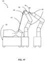
- FIGs. 1B-1Fshow various perspective views of the surgical robotic system 100 coupled to a robotic platform 150 (or surgical bed), according to various embodiments.
- FIG. 1Bshows a side view of the surgical robotic system 100 with the robotic arms 102 manipulating the endoscopic 118 to insert the endoscopic inside a patient's body, and the patient is lying on the robotic platform 150.
- FIG. 1Cshows a top view of the surgical robotic system 100 and the robotic platform 150, and the endoscopic 118 manipulated by the robotic arms is inserted inside the patient's body.
- FIG. 1Dshows a perspective view of the surgical robotic system 100 and the robotic platform 150, and the endoscopic 118 is controlled to be positioned horizontally parallel with the robotic platform.
- FIG. 1Bshows a side view of the surgical robotic system 100 with the robotic arms 102 manipulating the endoscopic 118 to insert the endoscopic inside a patient's body, and the patient is lying on the robotic platform 150.
- FIG. 1Cshows a top view of the surgical robotic system 100 and the robotic platform 150,
- FIG. 1Eshows another perspective view of the surgical robotic system 100 and the robotic platform 150, and the endoscopic 118 is controlled to be positioned relatively perpendicular to the robotic platform.
- the angle between the horizontal surface of the robotic platform 150 and the endoscopic 118is 75 degree.
- FIG. 1Fshows the perspective view of the surgical robotic system 100 and the robotic platform 150 shown in FIG. IE, and in more detail, the angle between the endoscopic 118 and the virtual line 160 connecting one end 180 of the endoscopic and the robotic arm 102 that is positioned relatively farther away from the robotic platform is 90 degree.
- FIG. 2shows an example command console 200 for the example surgical robotic system 100, according to one embodiment.
- the command console 200includes a console base 201, display modules 202, e.g., monitors, and control modules, e.g., a keyboard 203 and joystick 204.
- one or more of the command console 200 functionalitymay be integrated into a base 101 of the surgical robotic system 100 or another system communicatively coupled to the surgical robotic system 100.
- a user 205e.g., a physician, remotely controls the surgical robotic system 100 from an ergonomic position using the command console 200.
- the console base 201may include a central processing unit, a memory unit, a data bus, and associated data communication ports that are responsible for interpreting and processing signals such as camera imagery and tracking sensor data, e.g., from the endoscope 118 shown in FIG. 1 . In some embodiments, both the console base 201 and the base 101 perform signal processing for load-balancing.
- the console base 201may also process commands and instructions provided by the user 205 through the control modules 203 and 204.
- the control modulesmay include other devices, for example, computer mice, trackpads, trackballs, control pads, video game controllers, and sensors (e.g., motion sensors or cameras) that capture hand gestures and finger gestures.
- the user 205can control a surgical instrument such as the endoscope 118 using the command console 200 in a velocity mode or position control mode.
- velocity modethe user 205 directly controls pitch and yaw motion of a distal end of the endoscope 118 based on direct manual control using the control modules.
- movement on the joystick 204may be mapped to yaw and pitch movement in the distal end of the endoscope 118.
- the joystick 204can provide haptic feedback to the user 205.
- the joystick 204vibrates to indicate that the endoscope 118 cannot further translate or rotate in a certain direction.
- the command console 200can also provide visual feedback (e.g., pop-up messages) and/or audio feedback (e.g., beeping) to indicate that the endoscope 118 has reached maximum translation or rotation.
- the command console 200uses a three-dimensional (3D) map of a patient and pre-determined computer models of the patient to control a surgical instrument, e.g., the endoscope 118.
- the command console 200provides control signals to robotic arms 102 of the surgical robotic system 100 to manipulate the endoscope 118 to a target location. Due to the reliance on the 3D map, position control mode requires accurate mapping of the anatomy of the patient.
- users 205can manually manipulate robotic arms 102 of the surgical robotic system 100 without using the command console 200.
- the users 205may move the robotic arms 102, endoscopes 118, and other surgical equipment to access a patient.
- the surgical robotic system 100may rely on force feedback and inertia control from the users 205 to determine appropriate configuration of the robotic arms 102 and equipment.
- the display modules 202may include electronic monitors, virtual reality viewing devices, e.g., goggles or glasses, and/or other means of display devices.
- the display modules 202are integrated with the control modules, for example, as a tablet device with a touchscreen.
- the user 205can both view data and input commands to the surgical robotic system 100 using the integrated display modules 202 and control modules.
- the display modules 202can display 3D images using a stereoscopic device, e.g., a visor or goggle.
- the 3D imagesprovide an "endo view” (i.e., endoscopic view), which is a computer 3D model illustrating the anatomy of a patient.
- the "endo view”provides a virtual environment of the patient's interior and an expected location of an endoscope 118 inside the patient.
- a user 205compares the "endo view” model to actual images captured by a camera to help mentally orient and confirm that the endoscope 118 is in the correct-or approximately correct-location within the patient.
- the "endo view”provides information about anatomical structures, e.g., the shape of an intestine or colon of the patient, around the distal end of the endoscope 118.
- the display modules 202can simultaneously display the 3D model and computerized tomography (CT) scans of the anatomy the around distal end of the endoscope 118. Further, the display modules 202 may overlay the already determined navigation paths of the endoscope 118 on the 3D model and CT scans.
- CTcomputerized tomography
- a model of the endoscope 118is displayed with the 3D models to help indicate a status of a surgical procedure.
- the CT scansidentify a lesion in the anatomy where a biopsy may be necessary.
- the display modules 202may show a reference image captured by the endoscope 118 corresponding to the current location of the endoscope 118.
- the display modules 202may automatically display different views of the model of the endoscope 118 depending on user settings and a particular surgical procedure. For example, the display modules 202 show an overhead fluoroscopic view of the endoscope 118 during a navigation step as the endoscope 118 approaches an operative region of a patient.
- FIG. 3Ashows an isometric view of an example independent drive mechanism of the IDM 117 shown in FIG. 1 , according to one embodiment.
- the independent drive mechanismcan tighten or loosen the pull wires 321, 322, 323, and 324 (e.g., independently from each other) of an endoscope by rotating the output shafts 305, 306, 307, and 308 of the IDM 117, respectively.
- the output shafts 305, 306, 307, and 308transfer force down pull wires 321, 322, 323, and 324, respectively, through angular motion
- the pull wires 321, 322, 323, and 324transfer force back to the output shafts.
- the IDM 117 and/or the surgical robotic system 100can measure the transferred force using a sensor, e.g., a strain gauge further described below.
- FIG. 3Bshows a conceptual diagram that shows how forces may be measured by a strain gauge 334 of the independent drive mechanism shown in FIG. 3A , according to one embodiment.
- a force 331may direct away from the output shaft 305 coupled to the motor mount 333 of the motor 337. Accordingly, the force 331 results in horizontal displacement of the motor mount 333. Further, the strain gauge 334 horizontally coupled to the motor mount 333 experiences strain in the direction of the force 331. The strain may be measured as a ratio of the horizontal displacement of the tip 335 of strain gauge 334 to the overall horizontal width 336 of the strain gauge 334.
- the IDM 117includes additional sensors, e.g., inclinometers or accelerometers, to determine an orientation of the IDM 117. Based on measurements from the additional sensors and/or the strain gauge 334, the surgical robotic system 100 can calibrate readings from the strain gauge 334 to account for gravitational load effects. For example, if the IDM 117 is oriented on a horizontal side of the IDM 117, the weight of certain components of the IDM 117 may cause a strain on the motor mount 333. Accordingly, without accounting for gravitational load effects, the strain gauge 334 may measure strain that did not result from strain on the output shafts.
- additional sensorse.g., inclinometers or accelerometers
- FIG. 4Ashows a top view of an example endoscope 118, according to one embodiment.
- the endoscope 118includes a leader 415 tubular component nested or partially nested inside and longitudinally-aligned with a sheath 411 tubular component.
- the sheath 411includes a proximal sheath section 412 and distal sheath section 413.
- the leader 415has a smaller outer diameter than the sheath 411 and includes a proximal leader section 416 and distal leader section 417.
- the sheath base 414 and the leader base 418actuate the distal sheath section 413 and the distal leader section 417, respectively, for example, based on control signals from a user of a surgical robotic system 100.
- the sheath base 414 and the leader base 418are, e.g., part of the IDM 117 shown in FIG. 1 .
- Both the sheath base 414 and the leader base 418include drive mechanisms (e.g., the independent drive mechanism further described with reference to FIG. 3A-B in Section III. Instrument Device Manipulator) to control pull wires coupled to the sheath 411 and leader 415.
- the sheath base 414generates tensile loads on pull wires coupled to the sheath 411 to deflect the distal sheath section 413.
- the leader base 418generates tensile loads on pull wires coupled to the leader 415 to deflect the distal leader section 417.
- Both the sheath base 414 and leader base 418may also include couplings for the routing of pneumatic pressure, electrical power, electrical signals, or optical signals from IDMs to the sheath 411 and leader 414, respectively.
- a pull wiremay include a steel coil pipe along the length of the pull wire within the sheath 411 or the leader 415, which transfers axial compression back to the origin of the load, e.g., the sheath base 414 or the leader base 418, respectively.
- the endoscope 118can navigate the anatomy of a patient with ease due to the multiple degrees of freedom provided by pull wires coupled to the sheath 411 and the leader 415.
- pull wirescoupled to the sheath 411 and the leader 415.
- four or more pull wiresmay be used in either the sheath 411 and/or the leader 415, providing eight or more degrees of freedom.
- up to three pull wiresmay be used, providing up to six degrees of freedom.
- the sheath 411 and leader 415may be rotated up to 360 degrees along a longitudinal axis 406, providing more degrees of motion.
- the combination of rotational angles and multiple degrees of freedomprovides a user of the surgical robotic system 100 with a user friendly and instinctive control of the endoscope 118.
- FIG. 4Billustrates an example endoscope tip 430 of the endoscope 118 shown in FIG. 4A , according to one embodiment.
- the endoscope tip 430includes an imaging device 431 (e.g., a camera), illumination sources 432, and ends of EM coils 434.
- the illumination sources 432provide light to illuminate an interior portion of an anatomical space. The provided light allows the imaging device 431 to record images of that space, which can then be transmitted to a computer system such as command console 200 for processing as described herein.
- Electromagnetic coils 434 located on the tip 430may be used with an electromagnetic tracking system to detect the position and orientation of the endoscope tip 430 while it is disposed within an anatomical system.
- the coilsmay be angled to provide sensitivity to electromagnetic fields along different axes, giving the ability to measure a full 6 degrees of freedom: three positional and three angular.
- only a single coilmay be disposed within the endoscope tip 430, with its axis oriented along the endoscope shaft of the endoscope 118; due to the rotational symmetry of such a system, it is insensitive to roll about its axis, so only 5 degrees of freedom may be detected in such a case.
- the endoscope tip 430further comprises a working channel 436 through which surgical instruments, such as biopsy needles, may be inserted along the endoscope shaft, allowing access to the area near the endoscope tip.
- FIG. 5shows an example schematic setup of an EM tracking system 505 included in a surgical robotic system 500, according to one embodiment.
- multiple robot componentse.g., window field generator, reference sensors as described below
- the robotic surgical system 500includes a surgical bed 511 to hold a patient's body.
- Beneath the bed 511is the window field generator (WFG) 512 configured to sequentially activate a set of EM coils (e.g., the EM coils 434 shown in FIG. 4B ).
- the WFG 512generates an alternating current (AC) magnetic field over a wide volume; for example, in some cases it may create an AC field in a volume of about 0.5 x 0.5 x 0.5 m.
- ACalternating current
- a planar field generatormay be attached to a system arm adjacent to the patient and oriented to provide an EM field at an angle.
- Reference sensors 513may be placed on the patient's body to provide local EM fields to further increase tracking accuracy.
- Each of the reference sensors 513may be attached by cables 514 to a command module 515.
- the cables 514are connected to the command module 515 through interface units 516 which handle communications with their respective devices as well as providing power.
- the interface unit 516is coupled to a system control unit (SCU) 517 which acts as an overall interface controller for the various entities mentioned above.
- SCUsystem control unit
- the SCU 517also drives the field generators (e.g., WFG 512), as well as collecting sensor data from the interface units 516, from which it calculates the position and orientation of sensors within the body.
- the SCU 517may be coupled to a personal computer (PC) 518 to allow user access and control.
- PCpersonal computer
- the command module 515is also connected to the various IDMs 519 coupled to the surgical robotic system 500 as described herein.
- the IDMs 519are typically coupled to a single surgical robotic system (e.g., the surgical robotic system 500) and are used to control and receive data from their respective connected robotic components; for example, robotic endoscope tools or robotic arms. As described above, as an example, the IDMs 519 are coupled to an endoscopic tool (not shown here) of the surgical robotic system 500
- the command module 515receives data passed from the endoscopic tool.
- the type of received datadepends on the corresponding type of instrument attached.
- example received dataincludes sensor data (e.g., image data, EM data), robot data (e.g., endoscopic and IDM physical motion data), control data, and/or video data.
- sensor datae.g., image data, EM data
- robot datae.g., endoscopic and IDM physical motion data
- control datae.g., endoscopic and IDM physical motion data
- video datae.g., video data.
- a field-programmable gate array (FPGA) 520may be configured to handle image processing. Comparing data obtained from the various sensors, devices, and field generators allows the SCU 517 to precisely track the movements of different components of the surgical robotic system 500, and for example, positions and orientations of these components.
- FPGAfield-programmable gate array
- the EM tracking system 505may require a process known as "registration,” where the system finds the geometric transformation that aligns a single object between different coordinate systems. For instance, a specific anatomical site on a patient has two different representations in the 3D model coordinates and in the EM sensor coordinates. To be able to establish consistency and common language between these two different coordinate systems, the EM tracking system 505 needs to find the transformation that links these two representations, i.e., registration. For example, the position of the EM tracker relative to the position of the EM field generator may be mapped to a 3D coordinate system to isolate a location in a corresponding 3D model.
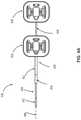
- FIGs. 6A-6Bshow an example anatomical lumen 600 and an example 3D model 620 of the anatomical lumen, according to one embodiment. More specifically, FIGs. 6A-6B illustrate relationship of centerline coordinates, diameter measurements and anatomical spaces between the actual anatomical lumen 600 and its 3D model 620.
- the anatomical lumen 600is roughly tracked longitudinally by centerline coordinates 601, 602, 603, 604, 605, and 606 where each centerline coordinate roughly approximates the center of the tomographic slice of the lumen.
- the centerline coordinatesare connected and visualized by a centerline 607.
- the volume of the lumencan be further visualized by measuring the diameter of the lumen at each centerline coordinate, e.g., coordinates 608, 609, 610, 611, 612, and 613 represent the measurements of the lumen 600 corresponding to coordinates 601, 602, 603, 604, 605, and 606.
- coordinates 608, 609, 610, 611, 612, and 613represent the measurements of the lumen 600 corresponding to coordinates 601, 602, 603, 604, 605, and 606.
- FIG. 6Bshows the example 3D model 620 of the anatomical lumen 600 shown in FIG. 6A , according to one embodiment.
- the anatomical lumen 600is visualized in 3D space by first locating the centerline coordinates 601, 602, 603, 604, 605, and 606 in 3D space based on the centerline 607.
- the lumen diameteris visualized as a 2D circular space (e.g., the 2D circular space 630) with diameters 608, 609, 610, 611, 612, and 613.
- the anatomical lumen 600is approximated and visualized as the 3D model 620.
- Centerline coordinatesmay also include markers to indicate point of interest for the physician, including lesions.
- a pre-operative software packageis also used to analyze and derive a navigation path based on the generated 3D model of the anatomical space. For example, the software package may derive a shortest navigation path to a single lesion (marked by a centerline coordinate) or to several lesions. This navigation path may be presented to the operator intra-operatively either in two-dimensions or three-dimensions depending on the operator's preference.
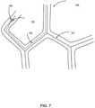
- FIG. 7shows a computer-generated 3D model 700 representing an anatomical space, according to one embodiment.
- the 3D model 700may be generated using centerline 701 that was obtained by reviewing CT scans that were generated preoperatively.
- computer softwaremay be able to map the navigation path 702 within the tubular network to access an operative site 703 within the 3D model 700.
- the operative site 703may be linked to an individual centerline coordinate 704, which allows a computer algorithm to topologically search the centerline coordinates of the 3D model 700 for the optimum path 702 within the tubular network.
- the distal end of the endoscopic tool within the patient's anatomyis tracked, and the tracked location of the endoscopic tool within the patient's anatomy is mapped and placed within a computer model, which enhances the navigational capabilities of the tubular network.
- a number of approachesmay be employed, either individually or in combination.
- a sensorsuch as an electromagnetic (EM) tracker
- EMelectromagnetic
- an EM trackerembedded in the endoscopic tool, measures the variation in the electromagnetic field created by one or more EM transmitters.
- the transmittersor field generators
- the transmittersmay be placed close to the patient (e.g., as part of the surgical bed) to create a low intensity magnetic field. This induces small-currents in sensor coils in the EM tracker, which are correlated to the distance and angle between the sensor and the generator.
- the electrical signalmay then be digitized by an interface unit (on-chip or PCB) and sent via cables/wiring back to the system cart and then to the command module.
- the datamay then be processed to interpret the current data and calculate the precise location and orientation of the sensor relative to the transmitters.
- Multiple sensorsmay be used at different locations in the endoscopic tool, for instance in leader and sheath in order to calculate the individual positions of those components. Accordingly, based on readings from an artificially-generated EM field, the EM tracker may detect changes in field strength as it moves through the patient's anatomy.
- FIGs. 8A-8Dshow example graphs 810-840 illustrating on-the-fly registration of an EM system to a 3D model of a path through a tubular network, according to one embodiment.
- the navigation configuration system described hereinallows for on-the-fly registration of the EM coordinates to the 3D model coordinates without the need for independent registration prior to an endoscopic procedure.
- FIG. 8Ashows that the coordinate systems of the EM tracking system and the 3D model are initially not registered to each other, and the graph 810 in FIG.
- FIG. 8Ashows the registered (or expected) location of an endoscope tip 801 moving along a planned navigation path 802 through a branched tubular network (not shown here), and the registered location of the instrument tip 801 as well as the planned path 802 are derived from the 3D model.
- the actual position of the tipis repeatedly measured by the EM tracking system 505, resulting in multiple measured location data points 803 based on EM data.
- the data points 803 derived from EM trackingare initially located far from the registered location of the endoscope tip 801 expected from the 3D model, reflecting the lack of registration between the EM coordinates and the 3D model coordinates. There may be several reasons for this, for example, even if the endoscope tip is being moved relatively smoothly through the tubular network, there may still be some visible scatter in the EM measurement, due to breathing movement of the lungs of the patient.
- the points on the 3D modelmay also be determined and adjusted based on correlation between the 3D model itself, image data received from optical sensors (e.g., cameras) and robot data from robot commands.
- the 3D transformation between these points and collected EM data pointswill determine the initial registration of the EM coordinate system to the 3D model coordinate system.
- FIG. 8Bshows a graph 820 at a later temporal stage compared with the graph 810, according to one embodiment. More specifically, the graph 820 shows the expected location of the endoscope tip 801 expected from the 3D model has been moved farther along the preplanned navigation path 802, as illustrated by the shift from the original expected position of the instrument tip 801 shown in FIG. 8A along the path to the position shown in FIG. 8B .
- additional data points 803have been recorded by the EM tracking system but the registration has not yet been updated based on the newly collected EM data. As a result, the data points 803 in FIG.
- sufficient datae.g., EM data
- a relatively more accurate estimatecan be derived from the transform needed to register the EM coordinates to those of the 3D model.
- the determination of sufficient datamay be made by threshold criteria such as total data accumulated or number of changes of direction. For example, in a branched tubular network such as a bronchial tube network, it may be judged that sufficient data have been accumulated after arriving at two branch points.
- FIG. 8Cshows a graph 830 shortly after the navigation configuration system has accumulated a sufficient amount of data to estimate the registration transform from EM to 3D model coordinates, according to one embodiment.
- the data points 803 in FIG. 8Chave now shifted from their previous position as shown in FIG. 8B as a result of the registration transform.
- the data points 803 derived from EM datais now falling along the planned navigation path 802 derived from the 3D model, and each data point among the data points 803 is now reflecting a measurement of the expected position of endoscope tip 801 in the coordinate system of the 3D model.
- the registration transformmay be updated to increase accuracy.
- the data used to determine the registration transformationmay be a subset of data chosen by a moving window, so that the registration may change over time, which gives the ability to account for changes in the relative coordinates of the EM and 3D models-for example, due to movement of the patient.
- FIG. 8Dshows an example graph 840 in which the expected location of the endoscope tip 801 has reached the end of the planned navigation path 802, arriving at the target location in the tubular network, according to one embodiment.
- the recorded EM data points 803is now generally tracks along the planned navigation path 802, which represents the tracking of the endoscope tip throughout the procedure.
- Each data pointreflects a transformed location due to the updated registration of the EM tracking system to the 3D model.
- each of the graphs shown in FIGs. 8A-8Dcan be shown sequentially on a display visible to a user as the endoscope tip is advanced in the tubular network.
- the processorcan be configured with instructions from the navigation configuration system such that the model shown on the display remains substantially fixed when the measured data points are registered to the display by shifting of the measured path shown on the display in order to allow the user to maintain a fixed frame of reference and to remain visually oriented on the model and on the planned path shown on the display.
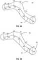
- FIGs. 8E-8Fshow effect of an example registration of the EM system to a 3D model of a branched tubular network, according to one embodiment.
- 3D graphs showing electromagnetic tracking data 852 and a model of a patient's bronchial system 854are illustrated without (shown in FIG. 8E ) and with (shown in FIG. 8F ) a registration transform.
- tracking data 860have a shape that corresponds to a path through the bronchial system 854, but that shape is subjected to an arbitrary offset and rotation.
- FIG. 8Fby applying the registration, the tracking data 852 are shifted and rotated, so that they correspond to a path through the bronchial system 854.
- a registration matrixcan be used to perform the registration between the EM tracking system and the 3D model, and as one example, the matrix may represent a translation and rotation in 6 dimensions.
- a rotational matrix and a translation vectorcan be used for performing the registration.
- applying a registration transforminvolves a shift from one coordinate system (x,y,z) to a new coordinate system (x',y',z') that may in general have its axes rotated to a different 3D orientation as well as having its origin shifted an arbitrary amount in each dimension.
- a rotation to an azimuthal angle of radians ⁇may be expressed by the matrix M 1
- a rotation to an inclination angle of ⁇ radiansmay be expressed by the matrix M 2 etc.
- further rotational matricesmay be written as the product of rotation matrices.
- a translation vector of ( ⁇ x ⁇ y ⁇ z)may be chosen to represent a translation of the origin in the x, y and z axes by ⁇ x, ⁇ y, and ⁇ z respectively.
- the registration transformmay be determined by such methods as singular value decomposition on a cross correlation matrix between measured EM positions and estimated positions in the 3D model.
- the transformation matrix componentsmay then be extracted from the decomposition, e.g., by identifying the appropriate principle components.
- An error signalmay also be generated from the residuals of the determined transform, and the size of the error signal may be used to determine a level of confidence in the position. As further data are taken and the registration transform is determined more accurately, this error signal may decrease, indicating an increasing confidence in positions estimated in this manner.
- FIGs. 9A-9Cshow example block diagrams of a navigation configuration system 900, according to one embodiment. More specifically, FIG. 9A shows a high-level overview of an example block diagram of the navigation configuration system 900, according to one embodiment.
- the navigation configuration system 900includes multiple input data stores, a navigation module 905 that receives various types of input data from the multiple input data stores, and an output navigation data store 990 that receives output navigation data from the navigation module.
- the block diagram of the navigation configuration system 900 shown in FIG. 9Ais merely one example, and in alternative embodiments not shown, the navigation configuration system 900 can include different and/or addition entities. Likewise, functions performed by various entities of the system 900 may differ according to different embodiments.
- the input datarefers to raw data gathered from and/or processed by input devices (e.g., command module, optical sensor, EM sensor, IDM) for generating estimated state information for the endoscope as well as output navigation data.
- the multiple input data stores 910-940include an image data store 910, an EM data store 920, a robot data store 930, and a 3D model data store 940.
- Each type of the input data storesstores the name-indicated type of data for access and use by the navigation module 905.
- Image datamay include one or more image frames captured by the imaging device at the instrument tip, as well as information such as frame rates or timestamps that allow a determination of the time elapsed between pairs of frames.
- Robot dataincludes data related to physical movement of the medical instrument or part of the medical instrument (e.g., the instrument tip or sheath) within the tubular network.
- Example robot dataincludes command data instructing the instrument tip to reach a specific anatomical site and/or change its orientation (e.g., with a specific pitch, roll, yaw, insertion, and retraction for one or both of a leader and a sheath) within the tubular network, insertion data representing insertion movement of the part of the medical instrument (e.g., the instrument tip or sheath), IDM data, and mechanical data representing mechanical movement of an elongate member of the medical instrument, for example motion of one or more pull wires, tendons or shafts of the endoscope that drive the actual movement of the medial instrument within the tubular network.
- EM datais collected by EM sensors and/or the EM tracking system as described above.
- 3D model datais derived from 2D CT scans as described above.
- the output navigation data store 990receives and stores output navigation data provided by the navigation module 905.
- Output navigation dataindicates information to assist in directing the medical instrument through the tubular network to arrive at a particular destination within the tubular network, and is based on estimated state information for the medical instrument at each instant time, the estimated state information including the location and orientation of the medical instrument within the tubular network.
- the output navigation dataindicating updates of movement and location/orientation information of the medical instrument is provided in real time, which better assists its navigation through the tubular network.
- the navigation module 905locates (or determines) the estimated state of the medical instrument within a tubular network.
- the navigation module 905further includes various algorithm modules, such as an EM-based algorithm module 950, an image-based algorithm module 960, and a robot-based algorithm module 970, that each may consume mainly certain types of input data and contribute a different type of data to a state estimator 980.
- algorithm modulessuch as an EM-based algorithm module 950, an image-based algorithm module 960, and a robot-based algorithm module 970, that each may consume mainly certain types of input data and contribute a different type of data to a state estimator 980.
- the different kinds of data output by these moduleslabeled EM-based data, the image-based data, and the robot-based data, may be generally referred to as "intermediate data" for sake of explanation.
- intermediate datafor sake of explanation.
- the detailed composition of each algorithm module and of the state estimator 980is more fully described in FIG. 9B below.
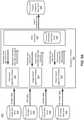
- FIG. 9Bshows an example block diagram of the navigation module 905 shown in FIG. 9A , according to one embodiment.
- the navigation module 905further includes a state estimator 980 as well as multiple algorithm modules that employ different algorithms for navigating through a tubular network.
- the state estimator 980is described first, followed by the description of the various modules that exchange data with the state estimator 980.
- the state estimator 980 included in the navigation module 905receives various intermediate data and provides the estimated state of the instrument tip as a function of time, where the estimated state indicates the estimated location and orientation information of the instrument tip within the tubular network.
- the estimated state dataare stored in the estimated data store 985 that is included in the state estimator 980.
- FIG. 9Cshows an example block diagram of the estimated state data store 985 included in the state estimator 980, according to one embodiment.
- the estimated state data store 985may include a bifurcation data store 1086, a position data store 1087, a depth data store 1088, and an orientation data store 1089, however this particular breakdown of data storage is merely one example, and in alternative embodiments not shown, different and/or additional data stores can be included in the estimated state data store 985.
- bifurcation datarefers to the location of the medical instrument with respect to the set of branches (e.g., bifurcation, trifurcation or a division into more than three branches) within the tubular network.
- the bifurcation datacan be set of branch choices elected by the instrument as it traverses through the tubular network, based on a larger set of available branches as provided, for example, by the 3D model which maps the entirety of the tubular network.
- the bifurcation datacan further include information in front of the location of the instrument tip, such as branches (bifurcations) that the instrument tip is near but has not yet traversed through, but which may have been detected, for example, based on the tip's current position information relative to the 3D model, or based on images captured of the upcoming bifurcations.
- branchesbranches
- Position dataindicates three-dimensional position of some part of the medical instrument within the tubular network or some part of the tubular network itself. Position data can be in the form of absolute locations or relative locations relative to, for example, the 3D model of the tubular network. As one example, position data can include the position of a specific branch.
- Depth dataindicates depth information of the instrument tip within the tubular network.
- Example depth dataincludes the total insertion (absolute) depth of the medical instrument into the patient as well as the (relative) depth within an identified branch. Depth data may be determined based on position data regarding both the tubular network and medical instrument.
- Orientation dataindicates orientation information of the instrument tip, and may include overall roll, pitch, and yaw in relation to the 3D model as well as pitch, roll, raw within an identified branch.
- the state estimator 980provides the estimated state data back to the algorithm modules for generating more accurate intermediate data, which the state estimator uses to generate improved and/or updated estimated states, and so on forming a feedback loop.
- the EM-based algorithm module 950recieves prior EM-based estimated state data (not shown in FIG. 9B ), also referred to as data associated with timestamp "t-1.”
- the state estimator 980uses this data to generate "estimated state data (prior)" that is associated with timestamp "t-1,” It then provides the data back to the EM-based algorithm module.
- the "estimated state data (prior)"may be based on a combination of different types of intermediate data (e.g., robotic data, image data) that is associated with timestamp "t-1" as generated and received from different algorithm modules.
- the EM- based algorithm module 950runs its algorithms using the estimated state data (prior) to output to the state estimator 980 improved and updated EM-based estimated state data, which is represented by "EM-based estimated state data (current)" here and associated with timestamp t. This process continues to repeat for future timestamps as well.
- the state estimator 980may use several different kinds of intermediate data to arrive at its estimates of the state of the medical instrument within the tubular network
- the state estimator 980is configured to account for the various different kinds of errors and uncertainty in both measurement and analysis that each type of underlying data (robotic, EM, image) and each type of algorithm module might create or carry through into the intermediate data used for consideration in determining the estimated state.
- robotEM
- imagea type of underlying data
- each type of algorithm modulemight create or carry through into the intermediate data used for consideration in determining the estimated state.
- the "probability" of the “probability distribution”, as used herein,refers to a likelihood of an estimation of a possible location and/or orientation of the medical instrument being correct. For example, different probabilities may be calculated by one of the algorithm modules indicating the relative likelihood that the medical instrument is in one of several different possible branches within the tubular network.
- the type of probability distributione.g., discrete distribution or continuous distribution
- is chosen to match features of an estimated statee.g., type of the estimated state, for example continuous position information vs. discrete branch choice).
- estimated states for identifying which segment the medical instrument is in for a trifurcationmay be represented by a discrete probability distribution, and may include three discrete values of 20%, 30% and 50% representing chance as being in the location inside each of the three branches as determined by one of the algorithm modules.
- the estimated statemay include a roll angle of the medical instrument of 40 ⁇ 5 degrees and a segment depth of the instrument tip within a branch may be is 4 ⁇ 1 mm, each represented by a Gaussian distribution which is a type of continuous probability distribution. Different methods can be used to generate the probabilities, which will vary by algorithm module as more fully described below with reference to later figures.
- the "confidence value,” as used herein,reflects a measure of confidence in the estimation of the state provided by one of the algorithms based one or more factors.
- factorssuch as distortion to EM Field, inaccuracy in EM registration, shift or movement of the patient, and respiration of the patient may affect the confidence in estimation of the state.
- the confidence value in estimation of the state provided by the EM-based algorithmsmay depend on the particular respiration cycle of the patient, movement of the patient or the EM field generators, and the location within the anatomy where the instrument tip locates.
- examples factors that may affect the confidence value in estimation of the stateinclude illumination condition for the location within the anatomy where the images are captured, presence of fluid, tissue, or other obstructions against or in front of the optical sensor capturing the images, respiration of the patient, condition of the tubular network of the patient itself (e.g., lung) such as the general fluid inside the tubular network and occlusion of the tubular network, and specific operating techniques used in, e.g., navigating or image capturing.
- one factormay be that a particular algorithm has differing levels of accuracy at different depths in a patient's lungs, such that relatively close to the airway opening, a particular algorithm may have a high confidence in its estimations of medical instrument location and orientation, but the further into the bottom of the lung the medical instrument travels that confidence value may drop.
- the confidence valueis based on one or more systemic factors relating to the process by which a result is determined, whereas probability is a relative measure that arises when trying to determine the correct result from multiple possibilities with a single algorithm based on underlying data.
- C EM , C Image , and C Robotrepresents confidence value corresponding to EM-based algorithm, image-based algorithm, and robot-based algorithm
- P i,EM' P i , Image , and P i , Robotrepresent the probabilities for segment i.
- a useris trying to identify segment where a instrument tip is located in a certain trifurcation within a central airway (the predicted region) of the tubular network, and three algorithms modules are used including EM-based algorithm, image-based algorithm, and robot-based algorithm.
- EM-based algorithmthe probability distribution corresponding to the EM-based algorithm may be 20% in the first branch, 30% in the second branch, and 50% in the third (last) branch, and the confidence value applied to this EM-based algorithm and the central airway is 80%.
- a probability distribution corresponding to the image-based algorithmmay be 40%, 20%, 40% for the first, second, and third branch, and the confidence value applied to this image-based algorithm is 30%; while a probability distribution corresponding to the robot-based algorithm may be 10%, 60%, 30% for the first, second, and third branch, and the confidence value applied to this image-based algorithm is 20%.
- the difference of confidence values applied to the EM-based algorithm and the image-based algorithmindicates that the EM-based algorithm may be a better choice for segment identification in the central airway, compared with the image-based algorithm.
- An example mathematical calculation of a final estimated statecan be:
- the output estimated state for the instrument tipcan be the result values (e.g., the resulting 30%, 42% and 58%), or derivative value from these result values such as the determination that the instrument tip is in the third branch.
- the estimated statemay be represented in a number of different ways.
- the estimated statemay further include an absolute depth from airway to location of the tip of the instrument, as well as a set of data representing the set of branches traversed by the instrument within the tubular network, the set being a subset of the entire set of branches provided by the 3D model of the patient's lungs, for example.
- the application of probability distribution and confidence value on estimated statesallows improved accuracy of estimation of location and/or orientation of the instrument itp within the tubular network.
- the algorithm modulesinclude an EM-based algorithm module 950, an image-based algorithm module 960, and a robot-based algorithm module 970.
- the algorithm modules shown in FIG. 9Bis merely one example, and in alternative embodiments, different and/additional algorithm modules involving different and/or additional navigation algorithms can also be included in the navigation module 905.
- the EM-based algorithm module 950further includes an EM registration module 952 and a branch selection module 954.
- the EM registration module 952performs registration of EM coordinates to 3D model coordinates.
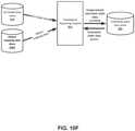
- FIG. 10Ashows an example block diagram of the EM registration module 952, according to one embodiment.
- the EM registration module 952receives as input, estimated state data (prior) (e.g., bifurcation data) from the estimated state data store 1086, the EM data from the EM data store 920, the 3D model data from the 3D model data store 940.
- estimated state datae.g., bifurcation data
- the EM registration module 952performs on-the-fly registration of the EM tracking data to the 3D model. After the initial registration is determined, the EM registration module 952 continually updates its estimate of the registration transform based on received data, so as to increase transform accuracy as well as to compensate for changes to the navigation configuration system 900, e.g., changes due to movement of the patient.
- the EM registration module 952outputs registration transform data to the registration transform data store 1053.
- the registration transform datareflects the best fit registration transform, and it can also be sent to the state estimator 980, as well as to the branch selection module 954.
- FIG. 10Bshows an example block diagram of the branch selection module 954, according to one embodiment.
- the branch selection module 954receives as inputs, estimated state data (prior) (e.g., bifurcation data) from the estimated state data store 985, the EM data from the EM data store 920, registration transform data from the registration transform data store 1053, as well as 3D model data from the 3D model data store 940. Based on the received data, the branch selection module 954 determines an estimate of the position and orientation of the endoscope tip relative to the 3D model of the tubular network and provides EM-based estimated state data (current) to the state estimator 980.
- estimated state datae.g., bifurcation data
- the EM-based estimated state datamay be represented as a probability distribution (e.g., a discrete distribution of 20%, 30% and 50% for three segments of a trifurcation, as described above.) Additionally, when at a bifurcation as indicated by the received bifurcation data, the branch selection module 954 may compare the pitch and yaw of the tip to the angles of each branch in the 3D model to estimate which branch has been selected by the user for traversal. The branch selection module 954 outputs the EM-based estimated state data (current) to the estimated data store 985.
- a probability distributione.g., a discrete distribution of 20%, 30% and 50% for three segments of a trifurcation, as described above.
- the image-based algorithm module 960uses image data to determine the estimated state of the instrument within the tubular network.
- the image-based algorithm module 960further includes one or more different types of image-based algorithm modules that employ different image-based algorithms. As shown in FIG. 9B , one example including an object-based algorithm module 962 is shown. In alternative embodiments not shown, other types of image-based algorithms may be employed and corresponding algorithm modules may be included in the image-based algorithm module 960.
- the object-based algorithm module 962detects and analyzes objects present in the field of view of the image data, such as branch openings or particles, to determine estimated state. In one embodiment, it includes an object detection module 963, and object mapping module 964, a topological reasoning module 965, and a motion estimation module 966. In some embodiments, it may or may not be necessary to apply the different modules 963, 964, 965 and 966 in a fixed sequential order, and when actually executing a process of object-based algorithm described by the object-based algorithm module 962, the order of employing each module within the module 962 is a different order than shown in FIG. 9B .
- the motion estimation module 963receives as inputs image data from the image data store 910, estimated state data (prior) (specifically bifurcation data), from the estimated state data store 985as well as the 3D model data from the 3D model data store 940. Based on the received image data, the motion estimation module 963 measures a movement of the medical instrument between multiple image frames based on the received image data.
- Example techniques usedinclude optical flow and image registration techniques, among others. This measurement determines a differential movement, such as forward-backward motion or roll motion, of the instrument tip in its own local frame of reference. This movement can be combined with the prior estimated state input to calculate a new estimated state.
- a forward (or backward) movementcan translate into an increase (or decrease) in depth relative to a prior estimated state.
- a differential rolltranslates into a change in roll angle relative to a prior estimated state.
- this movement measurementmay include an identification of an estimated new branch that the instrument tip is estimated to be entering or have entered. For example, if the bifurcation data indicates that the endoscope tip is at a branch point, pitch and yaw movements can be measured to determine changes in pointing angle, and the new estimated angle can be compared with the expected angles of different branches in the 3D model of the tubular network. A determination can then be made of which branch the endoscope is facing towards when it is moved into a new branch. Estimated state data reflecting each of these estimates of new position, orientation, and/or branch entry are output to the state estimator 980.
- FIG. 10Dshows an example block diagram of the object detection module 964, according to one example.
- the object detection module 964receives as inputs image data (e.g., image frames), and outputs object data to an object data store 1063 as well as estimated state data to the estimated state data store 985.
- Object dataindicates information about what objects were identified, as well as positions, orientations, and sizes of objects represented as probabilities.
- the object detection module 964detects, within an image, one or more objects and one or more features of the object(s) that may indicate branch points in a tubular network, and then determines their position, size, and orientation.
- Objectsmay be calculated or represented in the object detection module 964 as being two-dimensional shapes, such as circles/ovals/ellipses for detected branch points. This corresponds to the fact that the image data used to capture the objects are images from the camera on the instrument tip pointed usually along an axis substantially parallel to the direction of the segment in which the instrument is located.
- objects such as branches in the tubular networkappear as simple shapes such as ellipses in the images.
- each branchwill typically appear as a dark, approximately elliptical region, and these regions may be detected automatically by a processor, using region-detection algorithms such as maximally stable extremal regions (MSER) as objects. These regions may then be fit to define an object (e.g., ellipse), with appropriate free parameters such as ellipse center, major and minor axes, and angle within the image.
- MSERmaximally stable extremal regions
- the roll measurement and the identified matching between model lumens and lumens in the imageare also output to the state estimator 980, as well as topological reasoning module 966.
- An example of identified objects superimposed on an image of a bronchial network, along with a link joining their centers,is described with reference to FIGs. 11A-11B .
- airwaycan also be identified as an object present in the image data.
- the object detection module 964may use light reflective intensity combined with other techniques to identify airways.
- the object detection module 964may further track detected objects across a set of sequential image frames to detect which branch has been entered from among a set of possible branches in the tubular network. Tracking the relative positions of the objects within the image frames may be used to determine a local, absolute measurement of roll angle within a branched network.
- FIG. 10Eshows an example block diagram of the object mapping module 965, according to one embodiment.
- the object mapping module 965receives as inputs 3D model data from the 3D model data store 940, object data (e.g., detected objects such as shapes representing possible branches in the tubular network) from the object data store 1063, and estimated state data (prior) from the estimated state data store 985.
- object datae.g., detected objects such as shapes representing possible branches in the tubular network
- estimated state dataprior
- the object mapping module 965Based on the received input data, the object mapping module 965 outputs object mapping data to an object mapping data store 1065 as well as image-based estimated state data (current) to the estimated state data store 985.
- the object mapping dataindicates mapping information between physical branches (lumens) shown in image data (based on the detected objects) and virtual branch information generated by 3D model.
- the estimated state data (current) generated by module 965includes identification of each branch of the tubular network visible within the image as well as an estimate of the roll of the endoscope tip relative to the 3D model.
- the estimated state data (current)can be represented as a probability distribution.
- the identification of the visible lumensmay include coordinates in x and y of each identified lumen center within the image, for example based on object sizes correlated with the 3D model virtual image data, as well as an association of each identified lumen location with a particular branch of the tubular network.
- the virtual images of the tubular networkmay be pre-computed to speed up processing.
- the tubular networkmay be represented by a structure such as a tree diagram of lumen midlines, with each such midline describing a 3D path, so that an expected position of local branch centers as seen from any arbitrary perspective may be compared to the identified actual locations of branch centers based on EM data and/or robot data.
- FIGs. 11A-11Bshow an example object-to-lumen mapping performed by the object mapping module 965, according to one embodiment. More specifically, FIG. 11A shows two example identified objects 1101 and 1102 superimposed on an image of a bronchial network 1105 along with a link 1103 connecting centers of the two objects, according to one embodiment. In the illustrated example, the identified objects 1101 and 1102 are ellipse-shaped.
- FIG. 11Bshows a matching between airway lumens in an actual image 1110 of a real bronchial network and a corresponding virtual image 1120 from a 3D model of that same network, according to on embodiment.
- ellipsesare identified corresponding to two different branches, located with identified centers 1111 and 1112, which, in one embodiment, indicates centerline coordinates of the branches as described above in FIGs. 6A-6B .
- the 3D model virtual image 1120is a simulated representation of the real bronchial network shown in the actual image 1110, and the estimated centers 1121 and 1122 of the endoscope tip as determined by the state estimator 980 are shown corresponding to the positions of the identified centers 1111 and 1112.
- the 3D model image 1120may be rotated or translated to increase the closeness of fit between actual image 1110 and virtual image 1120, and the amount of roll needed for the rotation or translation can be output as a correction to the current estimated state (e.g., roll of the instrument tip).
- the probability applied to a possible estimated state as generated by the object mapping module 965is based on the closeness of fit between the identified centers 1111 and 1112 detected in the actual image 1110 and estimated centers 1121 and 1121 in the 3D model image 1120, and as one example, the probability of being in the lumen with identified center 1112 drops as the distance between the estimated center 1122 and identified center 1112 increases.
- FIG. 10Fshows an example block diagram of the topological reasoning module 966, according to one embodiment.
- the topological reasoning module 966receives as input image data from the 3D model data from the 3D model data store 940, object mapping data from the object mapping data store 1065, and estimated state data (prior) from the estimated state data store 985.
- the topological reasoning module 966determines which branch the endoscope tip is facing towards, thereby generating a prediction of which branch will be entered if the endoscope is moved forward. As above, the determination may be represented as a probability distribution. In one embodiment, when the instrument tip is moving forward, the topological reasoning module 966 determines that a new branch of the tubular network has been entered and identifies which branch the tip has moved into. The determination of which branch is being faced and which segment is entered may be made, for example, by comparing the relative sizes and locations of different identified objects (e.g., ellipses). As one example, as a particular lumen branch is entered, a corresponding detected object will grow larger in successive image frames, and will also become more centered in those frames.
- identified objectse.g., ellipses
- the topological reasoning module 966assigns an increasingly large probability to a corresponding estimated state as the endoscope tip moves towards the lumen associated with that object. Other branches are assigned correspondingly lower probabilities, until finally their object shapes disappear from images entirely. In one embodiment, the probability of the medical instrument being in those branches depends only on the probability that the branches were misidentified by the object mapping module 964.
- the output of the topological reasoning module 966is image-based estimated state data representing estimated probabilities of being in each of a set of possible branches within the branched network.
- the robot-based algorithm module 970uses robot data to provide robot-based estimated state data to the state estimator 980.
- FIG. 9Billustrates that the robot-based algorithm module 970 receives estimated state data (prior) and provides estimated state data (current) to state estimator 980.
- Robot dataincludes data related to physical movement of the medical instrument or part of the medical instrument (e.g., the instrument tip) within the tubular network.
- Example robot dataincludes command data instructing the instrument tip to reach a specific anatomical site and/or change its orientation (e.g., with a specific pitch, roll, yaw, insertion, and retraction for one or both of a leader and a sheath) within the tubular network, insertion data representing insertion movement of the part of the medical instrument (e.g., the instrument tip or sheath), IDM data, and mechanical data representing mechanical movement of an elongate member of the medical instrument, for example motion of one or more pull wires, tendons or shafts of the endoscope that drive the actual movement of the medical instrument within the tubular network.
- command datainstructing the instrument tip to reach a specific anatomical site and/or change its orientation (e.g., with a specific pitch, roll, yaw, insertion, and retraction for one or both of a leader and a sheath) within the tubular network
- insertion datarepresenting insertion movement of the part of the medical instrument (e.g., the instrument tip
- the estimated state data provided by the raw robotic input datais just that, an estimate as to actual motion.
- the estimated state data determined from the robotic datamay be represented in a probabilistic manner to represent this uncertainty in actual position information.
- FIG. 12shows an example process of generating a probability distribution over multiple values to determine an estimated state as may be performed by any of the individual algorithm modules described above, according to one embodiment. For sake of example, this process is described with respect to the estimated state module 980, but in practice may be used by any algorithm module.
- the state estimator 980first determines 1201 a prior probability distribution for the estimated state. As this stage, this probability distribution may be an initialized value distribution based, for example, on user input identifying a starting point near an entry point to a branched network. Subsequently, the distribution is determined from its previous output state estimate, adjusted based on the robotic, image, or EM input data.
- the new or updated probability distributionmay be estimated as centered 1 mm forward compared to the previous probability distribution. More generally, if a robot command is expected to change a variable x by a certain amount, represented by an expected distribution of value changes Q(Ax), the new estimated distribution P' (x) may be expressed as a convolution of the previous distribution P(x) with Q(Ax). This new estimated state is treated as a prior probability estimate of the variable for the subsequent steps.
- the state estimator 980receives an estimated value distribution for the estimated state based on one or more algorithm modules.
- This value distributionmay be represented in various ways, such as an expected value and an error range, or as an explicit distribution function over values, for example.
- the value distributioncontains, implicitly or explicitly, an expected value of the variable and some estimate of a range of error.
- the state estimator 980may treat the estimated value distribution as a normal distribution with a mean at the expected value and a standard deviation determined by the error range.
- the estimated value distributionwill typically comprise one or more probability values assigned to each of one or more branches, such that the total probability sums to one (or 100%).
- some branchesmay not be assigned with explicit probabilities, and the total probability may be less than 1, in which case the remaining probability can be treated as being uniformly distributed over all other branches.
- the state estimator 980generates a posterior probability distribution based on the received estimated value distribution from step 1202 and the determined prior probability distribution from step 1201.
- this posterior probability distributionis calculated as an application of Bayes' Theorem, which states that for an observation A, the posterior probability P ( x
- AP A
- the state estimator 980determines each of the quantities P(x), P(A), and P ( A
- the probability, P(A), of observing the tip to be in any given branchmay be set as 1/10.
- a modelmay be implemented to weight the possible observations A variably, for example, where branch sizes vary, P ( A ) may be set proportional to the size of branch A divided by the sum of all branch sizes, representing the idea that a randomly-placed tip is more likely to be found in a large branch than a small one.
- P (A)will be a probability density function over all possible observations A.
- the result of step 1203is a new probability distribution for values of the variable/state.
- the multiple independent measurementsmay be adjusted sequentially by taking the output of step 1203 as an input to step 1201, and using each new measurement as the estimated value distribution of step 1202. This generates a loop 1205 over measurements.
- step 1202may incorporate a plurality of independent estimated value distribution which may be combined into a single updated estimate in step 1203, using Bayesian conditional updating on multiple measurements.
- the motion estimation module 963may employ method 1200 with a process of taking the prior probability distribution of step 1201 as over an amount of movement (for example, an expected range of movement based on robot data), receiving an estimated value distribution in step 1202 over differential movement measurements, and generating a posterior probability distribution in step 1203 to estimate actual values of movement.
- This outputmay then be convolved with a prior estimated variable values (from a prior estimated state) to generate a posterior probability distribution for multiple values of the state.
- this new probability distributionis reported out in step 1204.
- the process 1200may be applied in parallel to generate new probability distributions for a plurality of variables (states), such as position, orientation, roll, depth, and/or branch.
- statessuch as position, orientation, roll, depth, and/or branch.
- the outputs of step 1204 for each such processmay be combined together to generate a new estimated state (E) 1202, which represents the output of the motion estimation module 963.
- the navigation module 905allows estimates of variables even when certain input data is not available. For example, prior to registration of the EM system, the output of the branch selection module 954 is ignored by the state estimator 980. Nonetheless, states representing location and/or orientation (e.g., tip insertion depth) may still be estimated based on available input data like the robot input data. Each time the instrument tip is ordered to move deeper into the branched network, the estimate state for the tip insertion depth may be updated based on this estimated movement. Thus, prior to registration, the tip insertion depth may be estimated based on robot data, and after registration, the depth may be estimated based on data from the branch selection module 954, but also partially based on robot data, with a weighting function.
- states representing location and/or orientatione.g., tip insertion depth
- the estimate state for the tip insertion depthmay be updated based on this estimated movement.
- the tip insertion depthmay be estimated based on robot data, and after registration, the depth may be estimated based on data from the branch selection module 954,
- the navigation configuration system 900demonstrates the ability to recover from errors by using the measurements from one module to contradict the measurements from another, allowing the system to "change its mind" about a previously-made determination. An example of how an error can be corrected is more fully described below with reference to FIG. 13 .
- FIG. 13shows an example of how an error can be corrected with navigation through a tubular network by the navigation configuration system 900, according to one embodiment.
- a simplified model of a bronchial tree 1300 with estimated statesis shown at four different temporal stages: states 1310, 1320, 1330, and 1340.
- states 1310, 1320, 1330, and 1340For each temporal stage, an estimated position (1312, 1322, 1332, and 1342, respectively) of an instrument tip used for the navigation is illustrated, and a corresponding actual position (1311, 1321, 1331, and 1341, respectively) of the tip is also illustrated.
- the accuracy of the estimated statesmay vary, e.g., the estimated states may first begin accurate, then becomes inaccurate, and then becomes accurate again.
- the actual position of the tipis 1311, at the upper branch of the bronchial tree 1300, and the navigation configuration system 900 accurately estimates that location as estimated position 1312.
- one or more modules inside the system 900may misidentify the branch based on probabilities provided by one or more of the algorithm modules, causing the system to conclude that the tip is entering the left branch 1345, when it is actually entering the right branch 1346.
- the state estimator 980initially assigns an 80% chance of being in the left branch and a 20% chance of being in the right branch.
- the branch selection module 954may thus more and more confidently report that the tip is probably in the right branch 1346 based on the shift in the probabilities provided by the underlying modules. Accordingly, the state estimator's 980 aggregate probability estimate may also shift, thereby resulting in an increase in the probability of being in the right branch 1346 and a corresponding decreasing the probability of being in the left branch 1345.
- the system 900may proceed to a state 1330, in which the tip is at the actual position 1331, arriving at a division into three branches. However, at this point in time state estimator 980 may still be estimating that the most likely state to be at estimated position 1332.
- the state estimator 980may be expecting a certain distance until the next branch division, in this example a two-way division, rather than three-way branch division.
- the branch selection module 954 and the object mapping module 964may strongly estimate that the tip is located in the branch shown on the right, which further strongly adjusts the probabilities of being in the left and right branches, leading to an almost certain assignment of the tip location to the correct branch, the right branch 1346 here.
- the state estimator 980correctly estimates the instrument tip be at estimated position 1342, very close to its actual location 1341. If the endoscope is along the user's desired path, the system 900 can now proceed to determine which branch of the three-way branch division is entered next. Alternately, the user can backtrack to travel down the left lumen of bronchial tree 1300. In some embodiments, this updated estimate is shown to a user on a display, so that the user can perceive that the previous estimates were in error, and that error has now been corrected.
- FIGs. 14A-14Cshow example pre-operative steps for preparation of a surgical instrument (e.g., an instrument tip) to navigation through an example tubular network, according to various embodiments.
- a surgical instrumente.g., an instrument tip
- FIG. 14Ashows an example pre-operative sequence of steps of a method 1400 for navigating the instrument tip to a particular site within the tubular network, according to one embodiment. Alongside each step of the method 1400, a corresponding image is shown to illustrate a representation of the involved data for planning a path and navigating through the tubular network.
- a CT scan of the tubular networkis obtained, and the data from the CT scan provides 3D information about the structure and connectivity of the tubular network.
- the image in step 1405shows a tomographic slice of a patient's lungs.
- a 3D modelis generated based on the obtained CT scan data, and the generated 3D model can be used to assign each branch of the tubular network with a unique identity, enabling convenient navigation within the network.
- the image in step 1410shows a 3D model of a patient's bronchial network.
- a target 1416is selected, and this target may be, for example, a lesion to biopsy, or a portion of organ tissue to repair surgically.
- the useris capable of selecting the location of the target by interfacing with a computer display that can show the 3D model, such as by clicking with a mouse or touching a touchscreen. The selected target may then be displayed to the user.
- the target 1416is marked within the 3D bronchial model generated from step 1410.
- a path 1421is automatically planned from an entry point 1422 to the target 1416, and the path 1421 identifies a sequence of branches within the network to travel through, so as to reach the target 1416.
- the tubular networkmay be tree-like, the path 1421 may be uniquely determined by the structure of the tubular network, while in another embodiment, the tubular network may be cyclic, and the path may be found by an appropriate algorithm such as a shortest-path algorithm.
- virtual endoscopy 1425may be performed to give the user a preview of the endoscopic procedure.
- the 3D model generated from step 1410is used to generate a sequence of 2D images as though seen by an endoscope tip while navigating the network corresponding to the 3D model.
- the path 1421may be shown as a curve that may be followed to get from the entry point 1422 to the target 1416.
- a virtual tool alignment procedure 1430may be performed to illustrate to the user how to manipulate endoscopic tools in order to perform a surgical procedure at the target.
- a virtual endoscopic biopsy needle 1431is maneuvered by the user in order to biopsy a lesion 1432 located beneath the surface of a bronchial tube. The lesion location is highlighted so that the user can align the needle to it, and then use the needle to pierce the surface of the bronchial tube and access the lesion underneath. This mimics the steps that will be taken during the actual surgical procedure, allowing the user to practice before performing surgery.
- FIG. 14Bshows an example user interface 1434 for navigation of a surgical instrument through a tubular network, according to one embodiment.
- the user interface 1434allows the user to have various views of the tubular network during an endoscopic procedure.
- the user interface 1434may show various navigation views to the user.
- the location of the endoscope tipmay be superimposed on a tomographic segment of the CT scan 1435, with a marker (e.g., crosshairs 1436) showing the location of the instrument.
- the CT imageis of a patient's lungs, and the endoscope used is a bronchoscope.
- the user interface 1434also shows a view 1440 representing a 3D model with a highlighted path 1441 and icons showing the endoscope location 1442 and the target location 1443. Some additional icons 1444 are also shown in the view 1440 for user interface controls enabling features as map pan and zoom.
- View 1445shows a virtual endoscope view from the estimated location of the tip that can be compared with a real-time view to confirm that the tip location has been estimated accurately.
- a path indicator 1446 and location/orientation indicator 1447 for aid in navigationis also shown in the view 1446.
- the upper leftshows state information 1448 determined by the state estimator 980, indicating that the current distance to target "t1" is 5.4 cm, and that the calculated roll angle is -139 degrees.
- View 1450shows a virtual view of the endoscope shaft 1451, displayed from a "third-person" viewpoint to the rear of the endoscope tip.
- the virtual viewcan be generated by assuming that the endoscope shaft lies along the path already traversed by the tip, and the view of the surrounding area is generated based on the 3D model in the vicinity of the chosen viewpoint. Alternately, the view may be generated from images taken while passing through that area earlier in the procedure.
- the virtual viewpointmay project ahead of the endoscope tip location, to show the next bifurcation. This view may further highlight the intended path, to inform the user in advance which way to steer when the endoscope tip reaches the next bifurcation.
- FIG. 14Cshows an example user interface 1480 for tool alignment and control during an endoscopic procedure, according to one embodiment.
- View 1455shows a tomographic view at a later stage in the procedure than view 1435, in which the endoscope tip is near the target and an endoscopic tool-in this case, a biopsy needle-has been deployed from the endoscope's working channel.
- the crosshairs 1436highlights the new position of the tip. Since the bronchoscope in the image is farther into the patient's lungs, the tomographic slice has changed to show a deeper cross-sectional segment.
- the icon locating the endoscope tiphas been replaced with one indicating the location and orientation of the needle.
- View 1460shows a map view of the 3D model, zoomed in around the target location 1443 and the tool icon 1461 representing the biopsy needle.
- Located at target 1443is a biopsy location 1466 to which a biopsy needle is to be applied.
- the endoscope tiphas been navigated to nearly the end of path 1441, to arrive at a location close enough to the target location 1443 so that the needle may reach the biopsy location 1466.
- View 1465shows a virtual view in the vicinity of target location 1443, highlighting a biopsy location 1466 to help the user visualize precisely where the needle is to be inserted to collect tissue for biopsy. Additional information, such as target size and distance to target may optionally be overlaid on the image.
- View 1670shows a close-up view of a 3D icon 1471 representing a biopsy needle, superimposed on a tomographic image of the patient's lungs.
- the roll of the instrumentis indicated by a multicolored pattern 1475 on the rear of the 3D icon 1471.
- this particular orientationrepresents a roll of 0 degrees, and the needle is currently 4 mm from the biopsy location 1466.
- a path 1474is displayed showing how the needle should be oriented and moved in order to contact the biopsy location 1466.
- a processor within the computer systemmay comprise one or more components to process electronic signals, and may comprise one or more of a central processor unit, a video processor, logic circuitry, gate array logic, filed programmable gate array, integrated circuit, or application specific integrated circuit.
- the computer systemincludes a central processing unit (CPU, also "processor” and “computer processor” herein), which can be a single core or multi core processor, or a plurality of processors for parallel processing.
- the CPUcan execute a sequence of machine-readable instructions, which can be embodied in a program or software.
- the instructionsmay be stored in a memory location. Examples of operations performed by the CPU can include fetch, decode, execute, and writeback.
- the CPUcan be part of a circuit, such as an integrated circuit.
- One or more other components of the systemcan be included in the circuit.
- the circuitcomprises an application specific integrated circuit (ASIC).
- ASICapplication specific integrated circuit
- the computer systemmay also include one or more of memory or memory locations (e.g., random-access memory, read-only memory, flash memory), electronic storage units (e.g., hard disk), communication interfaces (e.g., network adapters) for communicating with one or more other systems, and peripheral devices, such as caches, other memory, data storage and/or electronic display adapters.
- memory or memory locationse.g., random-access memory, read-only memory, flash memory
- electronic storage unitse.g., hard disk
- communication interfacese.g., network adapters
- peripheral devicessuch as caches, other memory, data storage and/or electronic display adapters.
- the memory, storage unit, interface, and peripheral devicesare in communication with the CPU through a communication bus, such as a motherboard.
- the storage unitcan be a data storage unit (or data repository) for storing data.
- the computer systemcan be operatively coupled to a computer network ("network") with the aid of the communication interface.
- the networkcan be the Internet, an internet and/or extranet, or an intranet and/or extranet that is in communication with the Internet.
- the networkin some cases is a telecommunication and/or data network, and can include can include one or more computer servers.
- the storage unitcan store files, such as drivers, libraries and saved programs.
- the storage unitcan store user data, e.g., user preferences and user programs.
- the computer systemin some cases can include one or more additional data storage units that are external to the computer system, such as located on a remote server that is in communication with the computer system through an intranet or the Internet.
- Methods as described hereincan be implemented by way of machine (e.g., computer processor) executable code stored on an electronic storage location of the computer system, such as, for example, on the memory or electronic storage unit.
- the machine executable or machine readable codecan be provided in the form of software.
- the codecan be executed by the processor.
- the codecan be retrieved from the storage unit and stored on the memory for ready access by the processor.
- the electronic storage unitcan be precluded, and machine-executable instructions are stored on memory.
- the codecan be pre-compiled and configured for use with a machine have a processer adapted to execute the code, or can be compiled during runtime.
- the codecan be supplied in a programming language that can be selected to enable the code to execute in a pre-compiled or as-compiled fashion.
- Methods and systems of the present disclosurecan be implemented by way of one or more methods.
- a methodcan be implemented with a processor as described herein, for example by way of software upon execution by one or more computer processors.
- any reference to " one embodiment” or “ an embodiment”means that a particular element, feature, structure, or characteristic described in connection with the embodiment is included in at least one embodiment.
- the appearances of the phrase “ in one embodiment” in various places in the specificationare not necessarily all referring to the same embodiment.
- Coupledmay be described using the expression “ coupled” and “connected” along with their derivatives.
- some embodimentsmay be described using the term “ coupled” to indicate that two or more elements are in direct physical or electrical contact.
- coupledmay also mean that two or more elements are not in direct contact with each other, but yet still co-operate or interact with each other.
- the embodimentsare not limited in this context unless otherwise explicitly stated.
- the terms “ comprises,” “ comprising,” “ includes,” “ including,” “ has,” “ having” or any other variation thereof,are intended to cover a non-exclusive inclusion.
- a process, method, article, or apparatus that comprises a list of elementsis not necessarily limited to only those elements but may include other elements not expressly listed or inherent to such process, method, article, or apparatus.
- " or”refers to an inclusive or and not to an exclusive or. For example, a condition A or B is satisfied by any one of the following: A is true (or present) and B is false (or not present), A is false (or not present) and B is true (or present), and both A and B are true (or present).
Landscapes
- Health & Medical Sciences (AREA)
- Engineering & Computer Science (AREA)
- Life Sciences & Earth Sciences (AREA)
- Surgery (AREA)
- Physics & Mathematics (AREA)
- Medical Informatics (AREA)
- General Health & Medical Sciences (AREA)
- Veterinary Medicine (AREA)
- Molecular Biology (AREA)
- Public Health (AREA)
- Animal Behavior & Ethology (AREA)
- Heart & Thoracic Surgery (AREA)
- Biomedical Technology (AREA)
- Nuclear Medicine, Radiotherapy & Molecular Imaging (AREA)
- Pathology (AREA)
- Biophysics (AREA)
- Radiology & Medical Imaging (AREA)
- Optics & Photonics (AREA)
- Theoretical Computer Science (AREA)
- General Physics & Mathematics (AREA)
- Computer Vision & Pattern Recognition (AREA)
- Pulmonology (AREA)
- Geometry (AREA)
- Computer Graphics (AREA)
- Software Systems (AREA)
- Robotics (AREA)
- Human Computer Interaction (AREA)
- Otolaryngology (AREA)
- Physiology (AREA)
- Signal Processing (AREA)
- Multimedia (AREA)
- Computing Systems (AREA)
- High Energy & Nuclear Physics (AREA)
- Quality & Reliability (AREA)
- Oral & Maxillofacial Surgery (AREA)
- Endoscopes (AREA)
Description
- This description generally relates to surgical robotics, and particularly to navigation of a medical instrument within a tubular network of a patient's body.
- Bronchoscopy is a medical procedure that allows a physician to examine the inside conditions of a patient's lung airways, such as bronchi and bronchioles. The lung airways carry air from the trachea, or windpipe, to the lungs. During the medical procedure, a thin, flexible tubular tool, known as a bronchoscope, may be inserted into the patient's mouth and passed down the patient's throat into his/her lung airways, and patients are generally anesthetized in order to relax their throats and lung cavities for surgical examinations and operations during the medical procedure.
- A conventional bronchoscope typically includes a light source and a small camera that allows a physician to inspect a patient's windpipe and airways, and a rigid tube may be used in conjunction with the bronchoscope for surgical purposes, e.g., when there is a significant amount of bleeding in the lungs of the patient or when a large object obstructs the throat of the patient. When the rigid tube is used, the patient is often anesthetized. Coincident with the rise of other advanced medical devices, the use of robotic bronchoscopes are increasingly becoming a reality. Robotic bronchoscopes provide tremendous advantages in navigation through tubular networks. They are easy to use and allow therapy and biopsies to be administered conveniently even during the bronchoscopy stage.
- Apart from mechanical devices or platforms, e.g., robotic bronchoscopes described above, various methods and software models may be used to help with the surgical operations. As an example, a computerized tomography (CT) scan of the patient's lungs is often performed during pre-operation of a surgical examination. Data from the CT scan may be used to generate a three dimensional (3D) model of airways of the patient's lungs, and the generated 3D model enables a physician to access a visual reference that may be useful during the operative procedure of the surgical examination. <Insert page 2a>
- However, previous techniques for navigation of tubular networks still have challenges, even when employing medical devices (e.g., robotic bronchoscopes) and when using existing methods (e.g., performing CT scans and generating 3D models). As one example, motion estimation of a medical device (e.g., a bronchoscope tool) inside a patient's body may not be accurate based on location and orientation change of the device, and as a result the device's position may not be accurately or correctly localized inside the patient's body in real time. Inaccurate location information for such an instrument may provide misleading information to the physician that uses the 3D model as a visual reference during medical operation procedures.
- Thus, there is a need for improved techniques for navigating through a network of tubular structures.
- The methods and apparatus disclosed herein provide improved navigation through tubular networks such as lung airways by providing improved estimation of location and orientation information of a medical instrument like a flexible or rigid elongated medical instrument (e.g., an endoscope) within the tubular network.
- As one example, the apparatus is a robotic endoscopic tool to acquire "raw" location and orientation information (collectively, input data) of a desired anatomical site or of the endoscopic tool within the tubular network. The endoscopic tool includes a flexible tip and an instrument device manipulator (IDM) coupled to the endoscopic tool. Devices such as an electromagnetic sensor (EM sensor), an imaging device (e.g., optical sensor), and a robotic control system controlling the medical instrument are coupled to the instrument tip to collect the input data as the endoscopic tool enters and navigates through the tubular network. The IDM is used to control movement and position of different robotic components (e.g., the endoscopic tool) of the surgical robotic system. A processor is coupled to the endoscopic tool to receive the input data to determine moment-by-moment movements and location and orientation information of the medical instrument (e.g., a instrument tip) within the tubular network.
- The processor is instructed by a navigation configuration system to use the input data to estimate the state of the medical instrument, which may include information such as position, orientation, relative and absolute depth, branch selection, etc. The processor may be Document
WO 2015/061756 discloses an endolumenal robotic system that provides the surgeon with the ability to drive a robotically-driven endoscopic device to a desired anatomical position in a patient. This document discloses an endoscopic tool coupled to a first instrument device manipulator, the endoscopic tool comprising a primary elongated body. In some embodiments, an electromagnetic tracker is coupled to the distal section of the primary elongated body. In some embodiments, an accelerometer is coupled to the distal section of the primary elongated body.
further instructed to use the estimated state to locate a specific site within a tubular network and/or to determine navigation information for what positions/orientations the medical instrument should travel through to arrive at the specific site, which may be referred to as the output data or navigation data. - The navigation configuration system further includes multiple algorithm modules employing various navigation algorithms for providing the estimated state and navigation data. Example algorithms used include EM-based algorithms, image-based algorithms, and robot-based algorithms. The estimated state and navigation data generated after employing these various algorithms makes use of any one or more of the EM-based input data, image-based input data, and robot-based input data.
- In some embodiments, probability distributions together with confidence values are generated by the algorithm modules, which are used to determine the medical instrument's estimated state. The "probability" of the "probability distribution", as used herein, refers to a likelihood of an estimation or identification of location and/or orientation of the medical instrument being correct. For example, different probabilities may be calculated indicating the relative likelihood that the medical instrument is in one of several different possible airways within the lung. In contrast, the "confidence value, as used herein, reflects a measure of confidence in the estimation of the state provided by one of the algorithms. For example, relatively close to the airway opening, a particular algorithm may have a high confidence in its estimations of medical instrument position and orientation; but further into the bottom of the lung the medical instrument travels, that confidence value may drop. Generally, the confidence value is based on one or more "external" factors relating to the process by which a result is determined, whereas probability is a relative measure that arises when trying to determine possible results from a single algorithm. The algorithms, probabilities, and confidence values may be variously combined to arrive at the estimated state and navigation data.
- In one embodiment, before executing an actual surgical operation on a patient, a sequence of pre-operative steps employing the improved navigation of surgical instruments (e.g., endoscopic) within a tubular network of the patient may be taken. Initially, a CT scan of the tubular network is obtained to generate a 3D model of the tubular network. A target area (e.g., a lesion to biopsy) within the tubular network is selected and a corresponding path for a surgical instrument to travel through the tubular network to reach the target area is automatically planned and displayed to a user (e.g., a physician responsible for the surgical operation). After the path is determined, a virtual endoscopic may be applied to travel through the tubular network to arrive at the target area. In the actual surgical operation, the CT scan, the generated 3D model as well as other input data (e.g., image data, EM data, robot data collected over the duration of the surgery) is combined and repeatedly analyzed during the surgery via the surgical configuration system to provide an estimation of the real-time movement information and location/orientation information of the surgical instrument (e.g., the endoscope) within the tubular network along with navigation information, which allows for more convenient operations by the physician.
Figure 1A (FIG. 1A ) shows an example surgical robotic system, according to one embodiment.FIGs. 1B-1F show various perspective views of a robotic platform coupled to the surgical robotic system shown inFIG. 1A , according to one embodiment.FIG. 2 shows an example command console for the example surgical robotic system, according to one embodiment.FIG. 3A shows an isometric view of an example independent drive mechanism of the instrument device manipulator (IDM) shown inFIG. 1A , according to one embodiment.FIG. 3B shows a conceptual diagram that shows how forces may be measured by a strain gauge of the independent drive mechanism shown inFIG. 3A , according to one embodiment.FIG. 4A shows a top view of an example endoscope, according to one embodiment.FIG. 4B shows an example endoscope tip of the endoscope shown inFIG. 4A , according to one embodiment.FIG. 5 shows an example schematic setup of an EM tracking system included in a surgical robotic system, according to one embodiment.FIGs. 6A-6B show an example anatomical lumen and an example 3D model of the anatomical lumen, according to one embodiment.FIG. 7 shows a computer-generated 3D model representing an anatomical space, according to one embodiment.FIGs. 8A-8D show example graphs illustrating on-the-fly registration of an EM system to a 3D model of a path through a tubular network, according to one embodiment.FIGs. 8E-8F show effect of an example registration of the EM system to a 3D model of a branched tubular network, according to one embodiment.FIG. 9A shows a high-level overview of an example block diagram of a navigation configuration system, according to one embodiment.FIG. 9B shows an example block diagram of the navigation module shown inFIG. 9A , according to one embodiment.FIG. 9C shows an example block diagram of the estimated state data store included in the state estimator, according to one embodiment.FIG. 10A shows an example block diagram of the EM registration module, according to one embodiment.FIG. 10B shows an example block diagram of the branch selection module, according to one embodiment.FIG. 10C shows an example block diagram of the motion estimation module, according to one embodiment.FIG. 10D shows an example block diagram of the object detection module, according to one example.FIG. 10E shows an example block diagram of the object mapping module, according to one embodiment.FIG. 10F shows an example block diagram of the topological reasoning module, according to one embodiment.FIG. 11A shows two example identified objects superimposed on an image of a bronchial network along with a link connecting centers of the two objects, according to one embodiment.FIG. 11B shows a matching between airway lumens in an actual image of a real bronchial network and a 3D model of the network, according to on embodiment.FIG. 12 shows an example process of generating a probability distribution over multiple values of an estimated state by the state estimator, according to one embodiment.FIG. 13 shows an example of how an error can be corrected with navigation through a tubular network of bronchial tubes by the navigation configuration system, according to one embodiment.FIG. 14A shows an example pre-operative sequence of steps of a method for navigating the instrument tip to a particular site within the tubular network, according to one embodiment.FIG. 14B shows an example user interface for navigation of a surgical instrument through a tubular network, according to one embodiment.FIG. 14C shows an example user interface for tool alignment and control during an endoscopic procedure, according to one embodiment.- Reference will now be made in detail to several embodiments, examples of which are illustrated in the accompanying figures. It is noted that wherever practicable similar or like reference numbers may be used in the figures and may indicate similar or like functionality. The figures depict embodiments of the described system (or method) for purposes of illustration only. One skilled in the art will readily recognize from the following description that alternative embodiments of the structures and methods illustrated herein may be employed without departing from the principles described herein.
FIG. 1A shows an example surgicalrobotic system 100, according to one embodiment. The surgicalrobotic system 100 includes a base 101 coupled to one or more robotic arms, e.g.,robotic arm 102. Thebase 101 is communicatively coupled to a command console, which is further described with reference toFIG. 2 in Section II. COMMAND CONSOLE. The base 101 can be positioned such that therobotic arm 102 has access to perform a surgical procedure on a patient, while a user such as a physician may control the surgicalrobotic system 100 from the comfort of the command console. In some embodiments, thebase 101 may be coupled to a surgical operating table or bed for supporting the patient. Though not shown inFIG. 1 for purposes of clarity, thebase 101 may include subsystems such as control electronics, pneumatics, power sources, optical sources, and the like. Therobotic arm 102 includesmultiple arm segments 110 coupled atjoints 111, which provides therobotic arm 102 multiple degrees of freedom, e.g., seven degrees of freedom corresponding to seven arm segments. The base 101 may contain a source ofpower 112,pneumatic pressure 113, and control and sensor electronics 114-including components such as a central processing unit, data bus, control circuitry, and memory-and related actuators such as motors to move therobotic arm 102. Theelectronics 114 in thebase 101 may also process and transmit control signals communicated from the command console.- In some embodiments, the
base 101 includeswheels 115 to transport the surgicalrobotic system 100. Mobility of the surgicalrobotic system 100 helps accommodate space constraints in a surgical operating room as well as facilitate appropriate positioning and movement of surgical equipment. Further, the mobility allows therobotic arms 102 to be configured such that therobotic arms 102 do not interfere with the patient, physician, anesthesiologist, or any other equipment. During procedures, a user may control therobotic arms 102 using control devices such as the command console. - In some embodiments, the
robotic arm 102 includes set up joints that use a combination of brakes and counter-balances to maintain a position of therobotic arm 102. The counter-balances may include gas springs or coil springs. The brakes, e.g., fail safe brakes, may be include mechanical and/or electrical components. Further, therobotic arms 102 may be gravity-assisted passive support type robotic arms. - Each
robotic arm 102 may be coupled to an instrument device manipulator (IDM) 117 using a mechanism changer interface (MCI) 116. TheIDM 117 can be removed and replaced with a different type of IDM, for example, a first type of IDM manipulates an endoscope, while a second type of IDM manipulates a laparoscope. TheMCI 116 includes connectors to transfer pneumatic pressure, electrical power, electrical signals, and optical signals from therobotic arm 102 to theIDM 117. TheMCI 116 can be a set screw or base plate connector. TheIDM 117 manipulates surgical instruments such as theendoscope 118 using techniques including direct drive, harmonic drive, geared drives, belts and pulleys, magnetic drives, and the like. TheMCI 116 is interchangeable based on the type ofIDM 117 and can be customized for a certain type of surgical procedure. The robotic 102 arm can include a joint level torque sensing and a wrist at a distal end, such as the KUKA AG® LBR5 robotic arm. [0046] Theendoscope 118 is a tubular and flexible surgical instrument that is inserted into the anatomy of a patient to capture images of the anatomy (e.g., body tissue). In particular, theendoscope 118 includes one or more imaging devices (e.g., cameras or other types of optical sensors) that capture the images. The imaging devices may include one or more optical components such as an optical fiber, fiber array, or lens. The optical components move along with the tip of theendoscope 118 such that movement of the tip of theendoscope 118 results in changes to the images captured by the imaging devices. Theendoscope 118 is further described with reference toFIGs. 3A-4B in Section IV. Endoscope. Robotic arms 102 of the surgicalrobotic system 100 manipulate theendoscope 118 using elongate movement members. The elongate movement members may include pull wires, also referred to as pull or push wires, cables, fibers, or flexible shafts. For example, therobotic arms 102 actuate multiple pull wires coupled to theendoscope 118 to deflect the tip of theendoscope 118. The pull wires may include both metallic and non-metallic materials such as stainless steel, Kevlar, tungsten, carbon fiber, and the like. Theendoscope 118 may exhibit nonlinear behavior in response to forces applied by the elongate movement members. The nonlinear behavior may be based on stiffness and compressibility of theendoscope 118, as well as variability in slack or stiffness between different elongate movement members.FIGs. 1B-1F show various perspective views of the surgicalrobotic system 100 coupled to a robotic platform 150 (or surgical bed), according to various embodiments. Specifically,FIG. 1B shows a side view of the surgicalrobotic system 100 with therobotic arms 102 manipulating the endoscopic 118 to insert the endoscopic inside a patient's body, and the patient is lying on therobotic platform 150.FIG. 1C shows a top view of the surgicalrobotic system 100 and therobotic platform 150, and the endoscopic 118 manipulated by the robotic arms is inserted inside the patient's body.FIG. 1D shows a perspective view of the surgicalrobotic system 100 and therobotic platform 150, and the endoscopic 118 is controlled to be positioned horizontally parallel with the robotic platform.FIG. 1E shows another perspective view of the surgicalrobotic system 100 and therobotic platform 150, and the endoscopic 118 is controlled to be positioned relatively perpendicular to the robotic platform. In more detail, in FIG. IE, the angle between the horizontal surface of therobotic platform 150 and the endoscopic 118 is 75 degree.FIG. 1F shows the perspective view of the surgicalrobotic system 100 and therobotic platform 150 shown in FIG. IE, and in more detail, the angle between the endoscopic 118 and thevirtual line 160 connecting oneend 180 of the endoscopic and therobotic arm 102 that is positioned relatively farther away from the robotic platform is 90 degree.FIG. 2 shows anexample command console 200 for the example surgicalrobotic system 100, according to one embodiment. Thecommand console 200 includes aconsole base 201,display modules 202, e.g., monitors, and control modules, e.g., akeyboard 203 andjoystick 204. In some embodiments, one or more of thecommand console 200 functionality may be integrated into abase 101 of the surgicalrobotic system 100 or another system communicatively coupled to the surgicalrobotic system 100. Auser 205, e.g., a physician, remotely controls the surgicalrobotic system 100 from an ergonomic position using thecommand console 200.- The
console base 201 may include a central processing unit, a memory unit, a data bus, and associated data communication ports that are responsible for interpreting and processing signals such as camera imagery and tracking sensor data, e.g., from theendoscope 118 shown inFIG. 1 . In some embodiments, both theconsole base 201 and the base 101 perform signal processing for load-balancing. Theconsole base 201 may also process commands and instructions provided by theuser 205 through thecontrol modules keyboard 203 andjoystick 204 shown inFIG. 2 , the control modules may include other devices, for example, computer mice, trackpads, trackballs, control pads, video game controllers, and sensors (e.g., motion sensors or cameras) that capture hand gestures and finger gestures. - The
user 205 can control a surgical instrument such as theendoscope 118 using thecommand console 200 in a velocity mode or position control mode. In velocity mode, theuser 205 directly controls pitch and yaw motion of a distal end of theendoscope 118 based on direct manual control using the control modules. For example, movement on thejoystick 204 may be mapped to yaw and pitch movement in the distal end of theendoscope 118. Thejoystick 204 can provide haptic feedback to theuser 205. For example, thejoystick 204 vibrates to indicate that theendoscope 118 cannot further translate or rotate in a certain direction. Thecommand console 200 can also provide visual feedback (e.g., pop-up messages) and/or audio feedback (e.g., beeping) to indicate that theendoscope 118 has reached maximum translation or rotation. - In position control mode, the
command console 200 uses a three-dimensional (3D) map of a patient and pre-determined computer models of the patient to control a surgical instrument, e.g., theendoscope 118. Thecommand console 200 provides control signals torobotic arms 102 of the surgicalrobotic system 100 to manipulate theendoscope 118 to a target location. Due to the reliance on the 3D map, position control mode requires accurate mapping of the anatomy of the patient. - In some embodiments,
users 205 can manually manipulaterobotic arms 102 of the surgicalrobotic system 100 without using thecommand console 200. During setup in a surgical operating room, theusers 205 may move therobotic arms 102,endoscopes 118, and other surgical equipment to access a patient. The surgicalrobotic system 100 may rely on force feedback and inertia control from theusers 205 to determine appropriate configuration of therobotic arms 102 and equipment. - The
display modules 202 may include electronic monitors, virtual reality viewing devices, e.g., goggles or glasses, and/or other means of display devices. In some embodiments, thedisplay modules 202 are integrated with the control modules, for example, as a tablet device with a touchscreen. Further, theuser 205 can both view data and input commands to the surgicalrobotic system 100 using the integrateddisplay modules 202 and control modules. - The
display modules 202 can display 3D images using a stereoscopic device, e.g., a visor or goggle. The 3D images provide an "endo view" (i.e., endoscopic view), which is acomputer 3D model illustrating the anatomy of a patient. The "endo view" provides a virtual environment of the patient's interior and an expected location of anendoscope 118 inside the patient. Auser 205 compares the "endo view" model to actual images captured by a camera to help mentally orient and confirm that theendoscope 118 is in the correct-or approximately correct-location within the patient. The "endo view" provides information about anatomical structures, e.g., the shape of an intestine or colon of the patient, around the distal end of theendoscope 118. Thedisplay modules 202 can simultaneously display the 3D model and computerized tomography (CT) scans of the anatomy the around distal end of theendoscope 118. Further, thedisplay modules 202 may overlay the already determined navigation paths of theendoscope 118 on the 3D model and CT scans. - In some embodiments, a model of the
endoscope 118 is displayed with the 3D models to help indicate a status of a surgical procedure. For example, the CT scans identify a lesion in the anatomy where a biopsy may be necessary. During operation, thedisplay modules 202 may show a reference image captured by theendoscope 118 corresponding to the current location of theendoscope 118. Thedisplay modules 202 may automatically display different views of the model of theendoscope 118 depending on user settings and a particular surgical procedure. For example, thedisplay modules 202 show an overhead fluoroscopic view of theendoscope 118 during a navigation step as theendoscope 118 approaches an operative region of a patient. FIG. 3A shows an isometric view of an example independent drive mechanism of theIDM 117 shown inFIG. 1 , according to one embodiment. The independent drive mechanism can tighten or loosen thepull wires output shafts IDM 117, respectively. Just as theoutput shafts wires pull wires IDM 117 and/or the surgicalrobotic system 100 can measure the transferred force using a sensor, e.g., a strain gauge further described below.FIG. 3B shows a conceptual diagram that shows how forces may be measured by astrain gauge 334 of the independent drive mechanism shown inFIG. 3A , according to one embodiment. Aforce 331 may direct away from theoutput shaft 305 coupled to themotor mount 333 of themotor 337. Accordingly, theforce 331 results in horizontal displacement of themotor mount 333. Further, thestrain gauge 334 horizontally coupled to themotor mount 333 experiences strain in the direction of theforce 331. The strain may be measured as a ratio of the horizontal displacement of thetip 335 ofstrain gauge 334 to the overallhorizontal width 336 of thestrain gauge 334.- In some embodiments, the
IDM 117 includes additional sensors, e.g., inclinometers or accelerometers, to determine an orientation of theIDM 117. Based on measurements from the additional sensors and/or thestrain gauge 334, the surgicalrobotic system 100 can calibrate readings from thestrain gauge 334 to account for gravitational load effects. For example, if theIDM 117 is oriented on a horizontal side of theIDM 117, the weight of certain components of theIDM 117 may cause a strain on themotor mount 333. Accordingly, without accounting for gravitational load effects, thestrain gauge 334 may measure strain that did not result from strain on the output shafts. FIG. 4A shows a top view of anexample endoscope 118, according to one embodiment. Theendoscope 118 includes aleader 415 tubular component nested or partially nested inside and longitudinally-aligned with asheath 411 tubular component. Thesheath 411 includes aproximal sheath section 412 anddistal sheath section 413. Theleader 415 has a smaller outer diameter than thesheath 411 and includes aproximal leader section 416 anddistal leader section 417. Thesheath base 414 and theleader base 418 actuate thedistal sheath section 413 and thedistal leader section 417, respectively, for example, based on control signals from a user of a surgicalrobotic system 100. Thesheath base 414 and theleader base 418 are, e.g., part of theIDM 117 shown inFIG. 1 .- Both the
sheath base 414 and theleader base 418 include drive mechanisms (e.g., the independent drive mechanism further described with reference toFIG. 3A-B in Section III. Instrument Device Manipulator) to control pull wires coupled to thesheath 411 andleader 415. For example, thesheath base 414 generates tensile loads on pull wires coupled to thesheath 411 to deflect thedistal sheath section 413. Similarly, theleader base 418 generates tensile loads on pull wires coupled to theleader 415 to deflect thedistal leader section 417. Both thesheath base 414 andleader base 418 may also include couplings for the routing of pneumatic pressure, electrical power, electrical signals, or optical signals from IDMs to thesheath 411 andleader 414, respectively. A pull wire may include a steel coil pipe along the length of the pull wire within thesheath 411 or theleader 415, which transfers axial compression back to the origin of the load, e.g., thesheath base 414 or theleader base 418, respectively. - The
endoscope 118 can navigate the anatomy of a patient with ease due to the multiple degrees of freedom provided by pull wires coupled to thesheath 411 and theleader 415. For example, four or more pull wires may be used in either thesheath 411 and/or theleader 415, providing eight or more degrees of freedom. In other embodiments, up to three pull wires may be used, providing up to six degrees of freedom. Thesheath 411 andleader 415 may be rotated up to 360 degrees along alongitudinal axis 406, providing more degrees of motion. The combination of rotational angles and multiple degrees of freedom provides a user of the surgicalrobotic system 100 with a user friendly and instinctive control of theendoscope 118. FIG. 4B illustrates anexample endoscope tip 430 of theendoscope 118 shown inFIG. 4A , according to one embodiment. InFIG. 4B , theendoscope tip 430 includes an imaging device 431 (e.g., a camera),illumination sources 432, and ends of EM coils 434. Theillumination sources 432 provide light to illuminate an interior portion of an anatomical space. The provided light allows theimaging device 431 to record images of that space, which can then be transmitted to a computer system such ascommand console 200 for processing as described herein.Electromagnetic coils 434 located on thetip 430 may be used with an electromagnetic tracking system to detect the position and orientation of theendoscope tip 430 while it is disposed within an anatomical system. In some embodiments, the coils may be angled to provide sensitivity to electromagnetic fields along different axes, giving the ability to measure a full 6 degrees of freedom: three positional and three angular. In other embodiments, only a single coil may be disposed within theendoscope tip 430, with its axis oriented along the endoscope shaft of theendoscope 118; due to the rotational symmetry of such a system, it is insensitive to roll about its axis, so only 5 degrees of freedom may be detected in such a case. Theendoscope tip 430 further comprises a workingchannel 436 through which surgical instruments, such as biopsy needles, may be inserted along the endoscope shaft, allowing access to the area near the endoscope tip.FIG. 5 shows an example schematic setup of anEM tracking system 505 included in a surgicalrobotic system 500, according to one embodiment. InFIG. 5 , multiple robot components (e.g., window field generator, reference sensors as described below) are included in theEM tracking system 505. The roboticsurgical system 500 includes asurgical bed 511 to hold a patient's body. Beneath thebed 511 is the window field generator (WFG) 512 configured to sequentially activate a set of EM coils (e.g., the EM coils 434 shown inFIG. 4B ). TheWFG 512 generates an alternating current (AC) magnetic field over a wide volume; for example, in some cases it may create an AC field in a volume of about 0.5 x 0.5 x 0.5 m.- Additional fields may be applied by further field generators to aid in tracking instruments within the body. For example, a planar field generator (PFG) may be attached to a system arm adjacent to the patient and oriented to provide an EM field at an angle. Reference sensors 513 may be placed on the patient's body to provide local EM fields to further increase tracking accuracy. Each of the reference sensors 513 may be attached by
cables 514 to a command module 515. Thecables 514 are connected to the command module 515 throughinterface units 516 which handle communications with their respective devices as well as providing power. Theinterface unit 516 is coupled to a system control unit (SCU) 517 which acts as an overall interface controller for the various entities mentioned above. TheSCU 517 also drives the field generators (e.g., WFG 512), as well as collecting sensor data from theinterface units 516, from which it calculates the position and orientation of sensors within the body. TheSCU 517 may be coupled to a personal computer (PC) 518 to allow user access and control. - The command module 515 is also connected to the
various IDMs 519 coupled to the surgicalrobotic system 500 as described herein. TheIDMs 519 are typically coupled to a single surgical robotic system (e.g., the surgical robotic system 500) and are used to control and receive data from their respective connected robotic components; for example, robotic endoscope tools or robotic arms. As described above, as an example, theIDMs 519 are coupled to an endoscopic tool (not shown here) of the surgicalrobotic system 500 - The command module 515 receives data passed from the endoscopic tool. The type of received data depends on the corresponding type of instrument attached. For example, example received data includes sensor data (e.g., image data, EM data), robot data (e.g., endoscopic and IDM physical motion data), control data, and/or video data. To better handle video data, a field-programmable gate array (FPGA) 520 may be configured to handle image processing. Comparing data obtained from the various sensors, devices, and field generators allows the
SCU 517 to precisely track the movements of different components of the surgicalrobotic system 500, and for example, positions and orientations of these components. - In order to track a sensor through the patient's anatomy, the
EM tracking system 505 may require a process known as "registration," where the system finds the geometric transformation that aligns a single object between different coordinate systems. For instance, a specific anatomical site on a patient has two different representations in the 3D model coordinates and in the EM sensor coordinates. To be able to establish consistency and common language between these two different coordinate systems, theEM tracking system 505 needs to find the transformation that links these two representations, i.e., registration. For example, the position of the EM tracker relative to the position of the EM field generator may be mapped to a 3D coordinate system to isolate a location in a corresponding 3D model. FIGs. 6A-6B show an exampleanatomical lumen 600 and anexample 3D model 620 of the anatomical lumen, according to one embodiment. More specifically,FIGs. 6A-6B illustrate relationship of centerline coordinates, diameter measurements and anatomical spaces between the actualanatomical lumen 600 and its3D model 620. InFIG. 6A , theanatomical lumen 600 is roughly tracked longitudinally by centerline coordinates 601, 602, 603, 604, 605, and 606 where each centerline coordinate roughly approximates the center of the tomographic slice of the lumen. The centerline coordinates are connected and visualized by acenterline 607. The volume of the lumen can be further visualized by measuring the diameter of the lumen at each centerline coordinate, e.g., coordinates 608, 609, 610, 611, 612, and 613 represent the measurements of thelumen 600 corresponding tocoordinates FIG. 6B shows theexample 3D model 620 of theanatomical lumen 600 shown inFIG. 6A , according to one embodiment. InFIG. 6B , theanatomical lumen 600 is visualized in 3D space by first locating the centerline coordinates 601, 602, 603, 604, 605, and 606 in 3D space based on thecenterline 607. As one example, at each centerline coordinate, the lumen diameter is visualized as a 2D circular space (e.g., the 2D circular space 630) withdiameters anatomical lumen 600 is approximated and visualized as the3D model 620. More accurate approximations may be determined by increasing the resolution of the centerline coordinates and measurements, i.e., increasing the density of centerline coordinates and measurements for a given lumen or subsection. Centerline coordinates may also include markers to indicate point of interest for the physician, including lesions.- In some embodiments, a pre-operative software package is also used to analyze and derive a navigation path based on the generated 3D model of the anatomical space. For example, the software package may derive a shortest navigation path to a single lesion (marked by a centerline coordinate) or to several lesions. This navigation path may be presented to the operator intra-operatively either in two-dimensions or three-dimensions depending on the operator's preference.
FIG. 7 shows a computer-generated3D model 700 representing an anatomical space, according to one embodiment. As discussed above inFIGs. 6A-6B , the3D model 700 may be generated usingcenterline 701 that was obtained by reviewing CT scans that were generated preoperatively. In some embodiments, computer software may be able to map thenavigation path 702 within the tubular network to access anoperative site 703 within the3D model 700. In some embodiments, theoperative site 703 may be linked to an individual centerline coordinate 704, which allows a computer algorithm to topologically search the centerline coordinates of the3D model 700 for theoptimum path 702 within the tubular network.- In some embodiments, the distal end of the endoscopic tool within the patient's anatomy is tracked, and the tracked location of the endoscopic tool within the patient's anatomy is mapped and placed within a computer model, which enhances the navigational capabilities of the tubular network. In order to track the distal working end of the endoscopic tool, i.e., location and orientation of the working end, a number of approaches may be employed, either individually or in combination.
- In a sensor-based approach to localization, a sensor, such as an electromagnetic (EM) tracker, may be coupled to the distal working end of the endoscopic tool to provide a real-time indication of the progression of the endoscopic tool. In EM-based tracking, an EM tracker, embedded in the endoscopic tool, measures the variation in the electromagnetic field created by one or more EM transmitters. The transmitters (or field generators), may be placed close to the patient (e.g., as part of the surgical bed) to create a low intensity magnetic field. This induces small-currents in sensor coils in the EM tracker, which are correlated to the distance and angle between the sensor and the generator. The electrical signal may then be digitized by an interface unit (on-chip or PCB) and sent via cables/wiring back to the system cart and then to the command module. The data may then be processed to interpret the current data and calculate the precise location and orientation of the sensor relative to the transmitters. Multiple sensors may be used at different locations in the endoscopic tool, for instance in leader and sheath in order to calculate the individual positions of those components. Accordingly, based on readings from an artificially-generated EM field, the EM tracker may detect changes in field strength as it moves through the patient's anatomy.
FIGs. 8A-8D show example graphs 810-840 illustrating on-the-fly registration of an EM system to a 3D model of a path through a tubular network, according to one embodiment. The navigation configuration system described herein allows for on-the-fly registration of the EM coordinates to the 3D model coordinates without the need for independent registration prior to an endoscopic procedure. In more detail,FIG. 8A shows that the coordinate systems of the EM tracking system and the 3D model are initially not registered to each other, and thegraph 810 inFIG. 8A shows the registered (or expected) location of anendoscope tip 801 moving along a plannednavigation path 802 through a branched tubular network (not shown here), and the registered location of theinstrument tip 801 as well as theplanned path 802 are derived from the 3D model. The actual position of the tip is repeatedly measured by theEM tracking system 505, resulting in multiple measuredlocation data points 803 based on EM data. As shown inFIG. 8A , the data points 803 derived from EM tracking are initially located far from the registered location of theendoscope tip 801 expected from the 3D model, reflecting the lack of registration between the EM coordinates and the 3D model coordinates. There may be several reasons for this, for example, even if the endoscope tip is being moved relatively smoothly through the tubular network, there may still be some visible scatter in the EM measurement, due to breathing movement of the lungs of the patient.- The points on the 3D model may also be determined and adjusted based on correlation between the 3D model itself, image data received from optical sensors (e.g., cameras) and robot data from robot commands. The 3D transformation between these points and collected EM data points will determine the initial registration of the EM coordinate system to the 3D model coordinate system.
FIG. 8B shows agraph 820 at a later temporal stage compared with thegraph 810, according to one embodiment. More specifically, thegraph 820 shows the expected location of theendoscope tip 801 expected from the 3D model has been moved farther along thepreplanned navigation path 802, as illustrated by the shift from the original expected position of theinstrument tip 801 shown inFIG. 8A along the path to the position shown inFIG. 8B . During the EM tracking between generation of thegraph 810 and generation ofgraph 820,additional data points 803 have been recorded by the EM tracking system but the registration has not yet been updated based on the newly collected EM data. As a result, the data points 803 inFIG. 8B are clustered along avisible path 814, but that path differs in location and orientation from the plannednavigation path 802 the endoscope tip is being directed by the operator to travel along. Eventually, once sufficient data (e.g., EM data) is accumulated, compared with using only the 3D model or only the EM data, a relatively more accurate estimate can be derived from the transform needed to register the EM coordinates to those of the 3D model. The determination of sufficient data may be made by threshold criteria such as total data accumulated or number of changes of direction. For example, in a branched tubular network such as a bronchial tube network, it may be judged that sufficient data have been accumulated after arriving at two branch points.FIG. 8C shows agraph 830 shortly after the navigation configuration system has accumulated a sufficient amount of data to estimate the registration transform from EM to 3D model coordinates, according to one embodiment. The data points 803 inFIG. 8C have now shifted from their previous position as shown inFIG. 8B as a result of the registration transform. As shown inFIG. 8C , the data points 803 derived from EM data is now falling along the plannednavigation path 802 derived from the 3D model, and each data point among the data points 803 is now reflecting a measurement of the expected position ofendoscope tip 801 in the coordinate system of the 3D model. In some embodiments, as further data are collected, the registration transform may be updated to increase accuracy. In some cases, the data used to determine the registration transformation may be a subset of data chosen by a moving window, so that the registration may change over time, which gives the ability to account for changes in the relative coordinates of the EM and 3D models-for example, due to movement of the patient.FIG. 8D shows anexample graph 840 in which the expected location of theendoscope tip 801 has reached the end of the plannednavigation path 802, arriving at the target location in the tubular network, according to one embodiment. As shown inFIG. 8D , the recorded EM data points 803 is now generally tracks along the plannednavigation path 802, which represents the tracking of the endoscope tip throughout the procedure. Each data point reflects a transformed location due to the updated registration of the EM tracking system to the 3D model.- In some embodiments, each of the graphs shown in
FIGs. 8A-8D can be shown sequentially on a display visible to a user as the endoscope tip is advanced in the tubular network. In some embodiments, the processor can be configured with instructions from the navigation configuration system such that the model shown on the display remains substantially fixed when the measured data points are registered to the display by shifting of the measured path shown on the display in order to allow the user to maintain a fixed frame of reference and to remain visually oriented on the model and on the planned path shown on the display. FIGs. 8E-8F show effect of an example registration of the EM system to a 3D model of a branched tubular network, according to one embodiment. InFIGs. 8E-8F , 3D graphs showingelectromagnetic tracking data 852 and a model of a patient'sbronchial system 854 are illustrated without (shown inFIG. 8E ) and with (shown inFIG. 8F ) a registration transform. InFIG. 8E , without registration, tracking data 860 have a shape that corresponds to a path through thebronchial system 854, but that shape is subjected to an arbitrary offset and rotation. InFIG. 8F , by applying the registration, the trackingdata 852 are shifted and rotated, so that they correspond to a path through thebronchial system 854.- In terms of detailed analysis (e.g., mathematical analysis) and methods of the registration, in some embodiments, a registration matrix can be used to perform the registration between the EM tracking system and the 3D model, and as one example, the matrix may represent a translation and rotation in 6 dimensions. In alternative embodiments, a rotational matrix and a translation vector can be used for performing the registration.


- From a perspective view of mathematical reasoning, as one example, applying a registration transform involves a shift from one coordinate system (x,y,z) to a new coordinate system (x',y',z') that may in general have its axes rotated to a different 3D orientation as well as having its origin shifted an arbitrary amount in each dimension. For example, a rotation to an azimuthal angle of radiansθ may be expressed by the matrix M1, a rotation to an inclination angle of ϕ radians may be expressed by the matrix M2 etc., and further rotational matrices may be written as the product of rotation matrices. Similarly, a translation vector of (Δx Δy Δz) may be chosen to represent a translation of the origin in the x, y and z axes by Δx, Δy, and Δz respectively.
- The registration transform may be determined by such methods as singular value decomposition on a cross correlation matrix between measured EM positions and estimated positions in the 3D model. The transformation matrix components may then be extracted from the decomposition, e.g., by identifying the appropriate principle components. An error signal may also be generated from the residuals of the determined transform, and the size of the error signal may be used to determine a level of confidence in the position. As further data are taken and the registration transform is determined more accurately, this error signal may decrease, indicating an increasing confidence in positions estimated in this manner.
FIGs. 9A-9C show example block diagrams of anavigation configuration system 900, according to one embodiment. More specifically,FIG. 9A shows a high-level overview of an example block diagram of thenavigation configuration system 900, according to one embodiment. InFIG. 9A , thenavigation configuration system 900 includes multiple input data stores, anavigation module 905 that receives various types of input data from the multiple input data stores, and an output navigation data store 990 that receives output navigation data from the navigation module. The block diagram of thenavigation configuration system 900 shown inFIG. 9A is merely one example, and in alternative embodiments not shown, thenavigation configuration system 900 can include different and/or addition entities. Likewise, functions performed by various entities of thesystem 900 may differ according to different embodiments.- The input data, as used herein, refers to raw data gathered from and/or processed by input devices (e.g., command module, optical sensor, EM sensor, IDM) for generating estimated state information for the endoscope as well as output navigation data. The multiple input data stores 910-940 include an
image data store 910, anEM data store 920, arobot data store 930, and a 3Dmodel data store 940. Each type of the input data stores stores the name-indicated type of data for access and use by thenavigation module 905. Image data may include one or more image frames captured by the imaging device at the instrument tip, as well as information such as frame rates or timestamps that allow a determination of the time elapsed between pairs of frames. Robot data includes data related to physical movement of the medical instrument or part of the medical instrument (e.g., the instrument tip or sheath) within the tubular network. Example robot data includes command data instructing the instrument tip to reach a specific anatomical site and/or change its orientation (e.g., with a specific pitch, roll, yaw, insertion, and retraction for one or both of a leader and a sheath) within the tubular network, insertion data representing insertion movement of the part of the medical instrument (e.g., the instrument tip or sheath), IDM data, and mechanical data representing mechanical movement of an elongate member of the medical instrument, for example motion of one or more pull wires, tendons or shafts of the endoscope that drive the actual movement of the medial instrument within the tubular network. EM data is collected by EM sensors and/or the EM tracking system as described above. 3D model data is derived from 2D CT scans as described above. - The output navigation data store 990 receives and stores output navigation data provided by the
navigation module 905. Output navigation data indicates information to assist in directing the medical instrument through the tubular network to arrive at a particular destination within the tubular network, and is based on estimated state information for the medical instrument at each instant time, the estimated state information including the location and orientation of the medical instrument within the tubular network. In one embodiment, as the medical instrument moves inside the tubular network, the output navigation data indicating updates of movement and location/orientation information of the medical instrument is provided in real time, which better assists its navigation through the tubular network. - To determine the output navigation data, the
navigation module 905 locates (or determines) the estimated state of the medical instrument within a tubular network. As shown inFIG. 9A , thenavigation module 905 further includes various algorithm modules, such as an EM-basedalgorithm module 950, an image-basedalgorithm module 960, and a robot-basedalgorithm module 970, that each may consume mainly certain types of input data and contribute a different type of data to astate estimator 980. As illustrated inFIG. 9A , the different kinds of data output by these modules, labeled EM-based data, the image-based data, and the robot-based data, may be generally referred to as "intermediate data" for sake of explanation. The detailed composition of each algorithm module and of thestate estimator 980 is more fully described inFIG. 9B below. FIG. 9B shows an example block diagram of thenavigation module 905 shown inFIG. 9A , according to one embodiment. As introduced above, thenavigation module 905 further includes astate estimator 980 as well as multiple algorithm modules that employ different algorithms for navigating through a tubular network. For clarity of description, thestate estimator 980 is described first, followed by the description of the various modules that exchange data with thestate estimator 980.- The
state estimator 980 included in thenavigation module 905 receives various intermediate data and provides the estimated state of the instrument tip as a function of time, where the estimated state indicates the estimated location and orientation information of the instrument tip within the tubular network. The estimated state data are stored in the estimateddata store 985 that is included in thestate estimator 980. FIG. 9C shows an example block diagram of the estimatedstate data store 985 included in thestate estimator 980, according to one embodiment. The estimatedstate data store 985 may include a bifurcation data store 1086, a position data store 1087, a depth data store 1088, and anorientation data store 1089, however this particular breakdown of data storage is merely one example, and in alternative embodiments not shown, different and/or additional data stores can be included in the estimatedstate data store 985.- The various stores introduced above represent estimated state data in a variety of ways. Specifically, bifurcation data refers to the location of the medical instrument with respect to the set of branches (e.g., bifurcation, trifurcation or a division into more than three branches) within the tubular network. For example, the bifurcation data can be set of branch choices elected by the instrument as it traverses through the tubular network, based on a larger set of available branches as provided, for example, by the 3D model which maps the entirety of the tubular network. The bifurcation data can further include information in front of the location of the instrument tip, such as branches (bifurcations) that the instrument tip is near but has not yet traversed through, but which may have been detected, for example, based on the tip's current position information relative to the 3D model, or based on images captured of the upcoming bifurcations.
- Position data indicates three-dimensional position of some part of the medical instrument within the tubular network or some part of the tubular network itself. Position data can be in the form of absolute locations or relative locations relative to, for example, the 3D model of the tubular network. As one example, position data can include the position of a specific branch.
- Depth data indicates depth information of the instrument tip within the tubular network. Example depth data includes the total insertion (absolute) depth of the medical instrument into the patient as well as the (relative) depth within an identified branch. Depth data may be determined based on position data regarding both the tubular network and medical instrument.
- Orientation data indicates orientation information of the instrument tip, and may include overall roll, pitch, and yaw in relation to the 3D model as well as pitch, roll, raw within an identified branch.
- Turning back to
FIG. 9B , thestate estimator 980 provides the estimated state data back to the algorithm modules for generating more accurate intermediate data, which the state estimator uses to generate improved and/or updated estimated states, and so on forming a feedback loop. For example, as shown inFIG. 9B , the EM-basedalgorithm module 950 recieves prior EM-based estimated state data (not shown inFIG. 9B ), also referred to as data associated with timestamp "t-1." Thestate estimator 980 uses this data to generate "estimated state data (prior)" that is associated with timestamp "t-1," It then provides the data back to the EM-based algorithm module. The "estimated state data (prior)" may be based on a combination of different types of intermediate data (e.g., robotic data, image data) that is associated with timestamp "t-1" as generated and received from different algorithm modules. Next, the EM- basedalgorithm module 950 runs its algorithms using the estimated state data (prior) to output to thestate estimator 980 improved and updated EM-based estimated state data, which is represented by "EM-based estimated state data (current)" here and associated with timestamp t. This process continues to repeat for future timestamps as well. - As the
state estimator 980 may use several different kinds of intermediate data to arrive at its estimates of the state of the medical instrument within the tubular network, thestate estimator 980 is configured to account for the various different kinds of errors and uncertainty in both measurement and analysis that each type of underlying data (robotic, EM, image) and each type of algorithm module might create or carry through into the intermediate data used for consideration in determining the estimated state. To address these, two concepts are discussed, that of a probability distribution and that of confidence value. - The "probability" of the "probability distribution", as used herein, refers to a likelihood of an estimation of a possible location and/or orientation of the medical instrument being correct. For example, different probabilities may be calculated by one of the algorithm modules indicating the relative likelihood that the medical instrument is in one of several different possible branches within the tubular network. In one embodiment, the type of probability distribution (e.g., discrete distribution or continuous distribution) is chosen to match features of an estimated state (e.g., type of the estimated state, for example continuous position information vs. discrete branch choice). As one example, estimated states for identifying which segment the medical instrument is in for a trifurcation may be represented by a discrete probability distribution, and may include three discrete values of 20%, 30% and 50% representing chance as being in the location inside each of the three branches as determined by one of the algorithm modules. As another example, the estimated state may include a roll angle of the medical instrument of 40 ± 5 degrees and a segment depth of the instrument tip within a branch may be is 4 ± 1 mm, each represented by a Gaussian distribution which is a type of continuous probability distribution. Different methods can be used to generate the probabilities, which will vary by algorithm module as more fully described below with reference to later figures.
- In contrast, the "confidence value," as used herein, reflects a measure of confidence in the estimation of the state provided by one of the algorithms based one or more factors. For the EM-based algorithms, factors such as distortion to EM Field, inaccuracy in EM registration, shift or movement of the patient, and respiration of the patient may affect the confidence in estimation of the state. Particularly, the confidence value in estimation of the state provided by the EM-based algorithms may depend on the particular respiration cycle of the patient, movement of the patient or the EM field generators, and the location within the anatomy where the instrument tip locates. For the image-based algorithms, examples factors that may affect the confidence value in estimation of the state include illumination condition for the location within the anatomy where the images are captured, presence of fluid, tissue, or other obstructions against or in front of the optical sensor capturing the images, respiration of the patient, condition of the tubular network of the patient itself (e.g., lung) such as the general fluid inside the tubular network and occlusion of the tubular network, and specific operating techniques used in, e.g., navigating or image capturing.
- For example one factor may be that a particular algorithm has differing levels of accuracy at different depths in a patient's lungs, such that relatively close to the airway opening, a particular algorithm may have a high confidence in its estimations of medical instrument location and orientation, but the further into the bottom of the lung the medical instrument travels that confidence value may drop. Generally, the confidence value is based on one or more systemic factors relating to the process by which a result is determined, whereas probability is a relative measure that arises when trying to determine the correct result from multiple possibilities with a single algorithm based on underlying data.
- As one example, a mathematical equation for calculating results of an estimated state represented by a discrete probability distribution (e.g., branch/segment identification for a trifurcation with three values of an estimated state involved) can be as follows:


- In the example mathematical equation above,Si(i = 1, 2, 3) represents possible example values of an estimated state in a case where 3 possible segments are identified or present in the 3D model,CEM, CImage, andCRobot represents confidence value corresponding to EM-based algorithm, image-based algorithm, and robot-based algorithm andPi,EM' Pi,Image, andPi,Robot represent the probabilities for segmenti.
- To better illustrate the concepts of probability distributions and confidence value associated with estimate states, a detailed example is provided here. In this example, a user is trying to identify segment where a instrument tip is located in a certain trifurcation within a central airway (the predicted region) of the tubular network, and three algorithms modules are used including EM-based algorithm, image-based algorithm, and robot-based algorithm. In this example, a probability distribution corresponding to the EM-based algorithm may be 20% in the first branch, 30% in the second branch, and 50% in the third (last) branch, and the confidence value applied to this EM-based algorithm and the central airway is 80%. For the same example, a probability distribution corresponding to the image-based algorithm may be 40%, 20%, 40% for the first, second, and third branch, and the confidence value applied to this image-based algorithm is 30%; while a probability distribution corresponding to the robot-based algorithm may be 10%, 60%, 30% for the first, second, and third branch, and the confidence value applied to this image-based algorithm is 20%. The difference of confidence values applied to the EM-based algorithm and the image-based algorithm indicates that the EM-based algorithm may be a better choice for segment identification in the central airway, compared with the image-based algorithm. An example mathematical calculation of a final estimated state can be:
- for the first branch: 20%∗80% + 40%∗30% + 10%∗20% = 30%; for the second branch: 30%∗80% + 20%∗30% + 60%∗20% = 42%; and for the third branch: 50%∗80% + 40%∗30% + 30%∗20% = 58%.
- In this example, the output estimated state for the instrument tip can be the result values (e.g., the resulting 30%, 42% and 58%), or derivative value from these result values such as the determination that the instrument tip is in the third branch.
- As above the estimated state may be represented in a number of different ways. For example, the estimated state may further include an absolute depth from airway to location of the tip of the instrument, as well as a set of data representing the set of branches traversed by the instrument within the tubular network, the set being a subset of the entire set of branches provided by the 3D model of the patient's lungs, for example. The application of probability distribution and confidence value on estimated states allows improved accuracy of estimation of location and/or orientation of the instrument itp within the tubular network.
- A shown in
FIG. 9B , the algorithm modules include an EM-basedalgorithm module 950, an image-basedalgorithm module 960, and a robot-basedalgorithm module 970. The algorithm modules shown inFIG. 9B is merely one example, and in alternative embodiments, different and/additional algorithm modules involving different and/or additional navigation algorithms can also be included in thenavigation module 905. - The EM-based
algorithm module 950 further includes anEM registration module 952 and abranch selection module 954. TheEM registration module 952 performs registration of EM coordinates to 3D model coordinates.FIG. 10A shows an example block diagram of theEM registration module 952, according to one embodiment. TheEM registration module 952 receives as input, estimated state data (prior) (e.g., bifurcation data) from the estimated state data store 1086, the EM data from theEM data store 920, the 3D model data from the 3Dmodel data store 940. - As described above with respect to Section V, based on the received data, the
EM registration module 952 performs on-the-fly registration of the EM tracking data to the 3D model. After the initial registration is determined, theEM registration module 952 continually updates its estimate of the registration transform based on received data, so as to increase transform accuracy as well as to compensate for changes to thenavigation configuration system 900, e.g., changes due to movement of the patient. TheEM registration module 952 outputs registration transform data to the registrationtransform data store 1053. In one embodiment, the registration transform data reflects the best fit registration transform, and it can also be sent to thestate estimator 980, as well as to thebranch selection module 954. FIG. 10B shows an example block diagram of thebranch selection module 954, according to one embodiment. Thebranch selection module 954 receives as inputs, estimated state data (prior) (e.g., bifurcation data) from the estimatedstate data store 985, the EM data from theEM data store 920, registration transform data from the registrationtransform data store 1053, as well as 3D model data from the 3Dmodel data store 940. Based on the received data, thebranch selection module 954 determines an estimate of the position and orientation of the endoscope tip relative to the 3D model of the tubular network and provides EM-based estimated state data (current) to thestate estimator 980. As an example, the EM-based estimated state data may be represented as a probability distribution (e.g., a discrete distribution of 20%, 30% and 50% for three segments of a trifurcation, as described above.) Additionally, when at a bifurcation as indicated by the received bifurcation data, thebranch selection module 954 may compare the pitch and yaw of the tip to the angles of each branch in the 3D model to estimate which branch has been selected by the user for traversal. Thebranch selection module 954 outputs the EM-based estimated state data (current) to the estimateddata store 985.- Turning back to
FIG. 9B , the image-basedalgorithm module 960 uses image data to determine the estimated state of the instrument within the tubular network. The image-basedalgorithm module 960 further includes one or more different types of image-based algorithm modules that employ different image-based algorithms. As shown inFIG. 9B , one example including an object-basedalgorithm module 962 is shown. In alternative embodiments not shown, other types of image-based algorithms may be employed and corresponding algorithm modules may be included in the image-basedalgorithm module 960. - The object-based
algorithm module 962 detects and analyzes objects present in the field of view of the image data, such as branch openings or particles, to determine estimated state. In one embodiment, it includes anobject detection module 963, and objectmapping module 964, atopological reasoning module 965, and amotion estimation module 966. In some embodiments, it may or may not be necessary to apply thedifferent modules algorithm module 962, the order of employing each module within themodule 962 is a different order than shown inFIG. 9B . - Turning to
FIG. 10C , themotion estimation module 963 receives as inputs image data from theimage data store 910, estimated state data (prior) (specifically bifurcation data), from the estimated state data store 985as well as the 3D model data from the 3Dmodel data store 940. Based on the received image data, themotion estimation module 963 measures a movement of the medical instrument between multiple image frames based on the received image data. Example techniques used include optical flow and image registration techniques, among others. This measurement determines a differential movement, such as forward-backward motion or roll motion, of the instrument tip in its own local frame of reference. This movement can be combined with the prior estimated state input to calculate a new estimated state. In particular, a forward (or backward) movement can translate into an increase (or decrease) in depth relative to a prior estimated state. Similarly, a differential roll translates into a change in roll angle relative to a prior estimated state. These measurements allow an estimation of movement through the tubular network. As above, these estimations may be represented as a probability distribution (e.g., a roll angle of the medical instrument of 40 ± 5 degrees represented by a Gaussian distribution). The output estimated state is stored in the estimatedstate data store 985. - In one embodiment, in a case where the estimated state and bifurcation data for a particular instant in time indicate that the instrument tip is at or near a branch point, this movement measurement may include an identification of an estimated new branch that the instrument tip is estimated to be entering or have entered. For example, if the bifurcation data indicates that the endoscope tip is at a branch point, pitch and yaw movements can be measured to determine changes in pointing angle, and the new estimated angle can be compared with the expected angles of different branches in the 3D model of the tubular network. A determination can then be made of which branch the endoscope is facing towards when it is moved into a new branch. Estimated state data reflecting each of these estimates of new position, orientation, and/or branch entry are output to the
state estimator 980. FIG. 10D shows an example block diagram of theobject detection module 964, according to one example. Theobject detection module 964 receives as inputs image data (e.g., image frames), and outputs object data to anobject data store 1063 as well as estimated state data to the estimatedstate data store 985. Object data indicates information about what objects were identified, as well as positions, orientations, and sizes of objects represented as probabilities.- Specifically, the
object detection module 964 detects, within an image, one or more objects and one or more features of the object(s) that may indicate branch points in a tubular network, and then determines their position, size, and orientation. Objects may be calculated or represented in theobject detection module 964 as being two-dimensional shapes, such as circles/ovals/ellipses for detected branch points. This corresponds to the fact that the image data used to capture the objects are images from the camera on the instrument tip pointed usually along an axis substantially parallel to the direction of the segment in which the instrument is located. As a consequence, objects such as branches in the tubular network appear as simple shapes such as ellipses in the images. In one embodiment, in a given image within a tubular network, each branch will typically appear as a dark, approximately elliptical region, and these regions may be detected automatically by a processor, using region-detection algorithms such as maximally stable extremal regions (MSER) as objects. These regions may then be fit to define an object (e.g., ellipse), with appropriate free parameters such as ellipse center, major and minor axes, and angle within the image. The roll measurement and the identified matching between model lumens and lumens in the image are also output to thestate estimator 980, as well astopological reasoning module 966. An example of identified objects superimposed on an image of a bronchial network, along with a link joining their centers, is described with reference toFIGs. 11A-11B . - In one embodiment, "airway" can also be identified as an object present in the image data. The
object detection module 964 may use light reflective intensity combined with other techniques to identify airways. - The
object detection module 964 may further track detected objects across a set of sequential image frames to detect which branch has been entered from among a set of possible branches in the tubular network. Tracking the relative positions of the objects within the image frames may be used to determine a local, absolute measurement of roll angle within a branched network. FIG. 10E shows an example block diagram of theobject mapping module 965, according to one embodiment. Theobject mapping module 965 receives asinputs 3D model data from the 3Dmodel data store 940, object data (e.g., detected objects such as shapes representing possible branches in the tubular network) from theobject data store 1063, and estimated state data (prior) from the estimatedstate data store 985.- Based on the received input data, the
object mapping module 965 outputs object mapping data to an objectmapping data store 1065 as well as image-based estimated state data (current) to the estimatedstate data store 985. As one example, the object mapping data indicates mapping information between physical branches (lumens) shown in image data (based on the detected objects) and virtual branch information generated by 3D model. The estimated state data (current) generated bymodule 965 includes identification of each branch of the tubular network visible within the image as well as an estimate of the roll of the endoscope tip relative to the 3D model. As above, the estimated state data (current) can be represented as a probability distribution. The identification of the visible lumens may include coordinates in x and y of each identified lumen center within the image, for example based on object sizes correlated with the 3D model virtual image data, as well as an association of each identified lumen location with a particular branch of the tubular network. - In some embodiments, since the 3D model is generated prior to the endoscopic procedure, the virtual images of the tubular network may be pre-computed to speed up processing. In alternative embodiments not shown, the tubular network may be represented by a structure such as a tree diagram of lumen midlines, with each such midline describing a 3D path, so that an expected position of local branch centers as seen from any arbitrary perspective may be compared to the identified actual locations of branch centers based on EM data and/or robot data.
FIGs. 11A-11B , show an example object-to-lumen mapping performed by theobject mapping module 965, according to one embodiment. More specifically,FIG. 11A shows two example identifiedobjects bronchial network 1105 along with alink 1103 connecting centers of the two objects, according to one embodiment. In the illustrated example, the identifiedobjects FIG. 11B shows a matching between airway lumens in anactual image 1110 of a real bronchial network and a correspondingvirtual image 1120 from a 3D model of that same network, according to on embodiment. In theactual image 1110, ellipses are identified corresponding to two different branches, located with identifiedcenters 1111 and 1112, which, in one embodiment, indicates centerline coordinates of the branches as described above inFIGs. 6A-6B . The 3D modelvirtual image 1120 is a simulated representation of the real bronchial network shown in theactual image 1110, and the estimatedcenters 1121 and 1122 of the endoscope tip as determined by thestate estimator 980 are shown corresponding to the positions of the identifiedcenters 1111 and 1112.- If both
images 3D model image 1120 may be rotated or translated to increase the closeness of fit betweenactual image 1110 andvirtual image 1120, and the amount of roll needed for the rotation or translation can be output as a correction to the current estimated state (e.g., roll of the instrument tip). - In one embodiment, the probability applied to a possible estimated state as generated by the
object mapping module 965 is based on the closeness of fit between the identifiedcenters 1111 and 1112 detected in theactual image 1110 and estimated centers 1121 and 1121 in the3D model image 1120, and as one example, the probability of being in the lumen with identified center 1112 drops as the distance between the estimatedcenter 1122 and identified center 1112 increases. FIG. 10F shows an example block diagram of thetopological reasoning module 966, according to one embodiment. Thetopological reasoning module 966 receives as input image data from the 3D model data from the 3Dmodel data store 940, object mapping data from the objectmapping data store 1065, and estimated state data (prior) from the estimatedstate data store 985.- Based on the received data, the
topological reasoning module 966 determines which branch the endoscope tip is facing towards, thereby generating a prediction of which branch will be entered if the endoscope is moved forward. As above, the determination may be represented as a probability distribution. In one embodiment, when the instrument tip is moving forward, thetopological reasoning module 966 determines that a new branch of the tubular network has been entered and identifies which branch the tip has moved into. The determination of which branch is being faced and which segment is entered may be made, for example, by comparing the relative sizes and locations of different identified objects (e.g., ellipses). As one example, as a particular lumen branch is entered, a corresponding detected object will grow larger in successive image frames, and will also become more centered in those frames. If this is behavior is identified for one of the objects, thetopological reasoning module 966 assigns an increasingly large probability to a corresponding estimated state as the endoscope tip moves towards the lumen associated with that object. Other branches are assigned correspondingly lower probabilities, until finally their object shapes disappear from images entirely. In one embodiment, the probability of the medical instrument being in those branches depends only on the probability that the branches were misidentified by theobject mapping module 964. The output of thetopological reasoning module 966 is image-based estimated state data representing estimated probabilities of being in each of a set of possible branches within the branched network. - The robot-based
algorithm module 970 uses robot data to provide robot-based estimated state data to thestate estimator 980.FIG. 9B illustrates that the robot-basedalgorithm module 970 receives estimated state data (prior) and provides estimated state data (current) tostate estimator 980. Robot data includes data related to physical movement of the medical instrument or part of the medical instrument (e.g., the instrument tip) within the tubular network. Example robot data includes command data instructing the instrument tip to reach a specific anatomical site and/or change its orientation (e.g., with a specific pitch, roll, yaw, insertion, and retraction for one or both of a leader and a sheath) within the tubular network, insertion data representing insertion movement of the part of the medical instrument (e.g., the instrument tip or sheath), IDM data, and mechanical data representing mechanical movement of an elongate member of the medical instrument, for example motion of one or more pull wires, tendons or shafts of the endoscope that drive the actual movement of the medical instrument within the tubular network. - Although in an ideal system, specifically input pitch, roll, yaw, insertion, and retraction commands given to the IDM to control the instrument tip would result in exactly-as-input changes in the motion of the instrument tip, in practice this is generally not the case. Friction in the system, nonlinearities in instrument motion, blockages, and other effects may cause the input motion to vary from the output motion. As such, the estimated state data provided by the raw robotic input data is just that, an estimate as to actual motion. As per the algorithms above, the estimated state data determined from the robotic data may be represented in a probabilistic manner to represent this uncertainty in actual position information.
FIG. 12 shows an example process of generating a probability distribution over multiple values to determine an estimated state as may be performed by any of the individual algorithm modules described above, according to one embodiment. For sake of example, this process is described with respect to the estimatedstate module 980, but in practice may be used by any algorithm module.- In
FIG. 12 , a process of a Bayesian estimation method is shown, and in alternative embodiments not shown, other methods of generating a probability distribution can also be employed. As shown inFIG. 12 , thestate estimator 980 first determines 1201 a prior probability distribution for the estimated state. As this stage, this probability distribution may be an initialized value distribution based, for example, on user input identifying a starting point near an entry point to a branched network. Subsequently, the distribution is determined from its previous output state estimate, adjusted based on the robotic, image, or EM input data. - For example, if the surgical
robotic system 100 commands to move the endoscope tip forward a certain distance, e.g., 1 mm, the new or updated probability distribution may be estimated as centered 1 mm forward compared to the previous probability distribution. More generally, if a robot command is expected to change a variable x by a certain amount, represented by an expected distribution of value changes Q(Ax), the new estimated distribution P' (x) may be expressed as a convolution of the previous distribution P(x) with Q(Ax). This new estimated state is treated as a prior probability estimate of the variable for the subsequent steps. - In the
next step 1202, thestate estimator 980 receives an estimated value distribution for the estimated state based on one or more algorithm modules. This value distribution may be represented in various ways, such as an expected value and an error range, or as an explicit distribution function over values, for example. In any case, the value distribution contains, implicitly or explicitly, an expected value of the variable and some estimate of a range of error. In some cases, only the expected value is transmitted and the error range is determined by thestate estimator 980, using a record of past performance or pre-calibrated values of reliability. In one embodiment, when using an expected value and an error range, thestate estimator 980 may treat the estimated value distribution as a normal distribution with a mean at the expected value and a standard deviation determined by the error range. In the case of a discrete variable or discrete state like branch identification, the estimated value distribution will typically comprise one or more probability values assigned to each of one or more branches, such that the total probability sums to one (or 100%). In some cases, some branches may not be assigned with explicit probabilities, and the total probability may be less than 1, in which case the remaining probability can be treated as being uniformly distributed over all other branches. - In
step 1203, thestate estimator 980 generates a posterior probability distribution based on the received estimated value distribution fromstep 1202 and the determined prior probability distribution fromstep 1201. As one example, this posterior probability distribution is calculated as an application of Bayes' Theorem, which states that for an observation A, the posterior probabilityP(x|A) of a variable having value x is given by the equation
- The
state estimator 980 determines each of the quantitiesP(x), P(A), andP(A|x) from the inputs generated duringsteps step 1201. Likewise,P(A|x) may be read from the function determined instep 1202.P (A), may be set as a constant representing the number of possible values of A. For example, when estimating a discrete probability distribution for what branch an endoscope tip is in encountering a division into a certain number (e.g., 10) of branches, the probability,P(A), of observing the tip to be in any given branch, may be set as 1/10. Alternatively, a model may be implemented to weight the possible observations A variably, for example, where branch sizes vary,P(A) may be set proportional to the size of branch A divided by the sum of all branch sizes, representing the idea that a randomly-placed tip is more likely to be found in a large branch than a small one. For continuous distributions, such as roll angle, depth, or orientation,P (A) will be a probability density function over all possible observations A. For example, if roll angle ranges from 0 to 2π radians,P (A) may be set to 1/(2π) for all values of A to represent an equally likely probability density of any roll angle being observed. More generally, givenP(x) as an estimate for the probability ofx, P(A) will be given by the formulaP(A) =P(A|x)P(x) +P(A|~x)P(~x), where~x means "not-x." - In one embodiment, the result of
step 1203 is a new probability distribution for values of the variable/state. In one embodiment, when each of multiple independent measurements relates to a given variable, the multiple independent measurements may be adjusted sequentially by taking the output ofstep 1203 as an input to step 1201, and using each new measurement as the estimated value distribution ofstep 1202. This generates aloop 1205 over measurements. Alternatively,step 1202 may incorporate a plurality of independent estimated value distribution which may be combined into a single updated estimate instep 1203, using Bayesian conditional updating on multiple measurements. - For example, if differential movement is being measured, the
motion estimation module 963 may employmethod 1200 with a process of taking the prior probability distribution ofstep 1201 as over an amount of movement (for example, an expected range of movement based on robot data), receiving an estimated value distribution instep 1202 over differential movement measurements, and generating a posterior probability distribution instep 1203 to estimate actual values of movement. This output may then be convolved with a prior estimated variable values (from a prior estimated state) to generate a posterior probability distribution for multiple values of the state. In some embodiments, once all measurements have been incorporated into an updated probability distribution, this new probability distribution is reported out instep 1204. Theprocess 1200 may be applied in parallel to generate new probability distributions for a plurality of variables (states), such as position, orientation, roll, depth, and/or branch. The outputs ofstep 1204 for each such process may be combined together to generate a new estimated state (E) 1202, which represents the output of themotion estimation module 963. - In some embodiments, the
navigation module 905 allows estimates of variables even when certain input data is not available. For example, prior to registration of the EM system, the output of thebranch selection module 954 is ignored by thestate estimator 980. Nonetheless, states representing location and/or orientation (e.g., tip insertion depth) may still be estimated based on available input data like the robot input data. Each time the instrument tip is ordered to move deeper into the branched network, the estimate state for the tip insertion depth may be updated based on this estimated movement. Thus, prior to registration, the tip insertion depth may be estimated based on robot data, and after registration, the depth may be estimated based on data from thebranch selection module 954, but also partially based on robot data, with a weighting function. - There is a possibility of over-determination/over-fitting of the location estimate for the instrument based on the many possible independent measurements introduced above, which include local measurements such as object-based image tracking, optical flow, global measurements such as EM tracking, and robotic input data based measurement. Consequently, the accuracy of estimated position within the branched network may be greater than the accuracy of estimates made using any one of the modules alone. Furthermore, in some embodiments, the
navigation configuration system 900 demonstrates the ability to recover from errors by using the measurements from one module to contradict the measurements from another, allowing the system to "change its mind" about a previously-made determination. An example of how an error can be corrected is more fully described below with reference toFIG. 13 . FIG. 13 shows an example of how an error can be corrected with navigation through a tubular network by thenavigation configuration system 900, according to one embodiment. InFIG. 13 , a simplified model of abronchial tree 1300 with estimated states is shown at four different temporal stages: states 1310, 1320, 1330, and 1340. For each temporal stage, an estimated position (1312, 1322, 1332, and 1342, respectively) of an instrument tip used for the navigation is illustrated, and a corresponding actual position (1311, 1321, 1331, and 1341, respectively) of the tip is also illustrated. In one embodiment, over time during the four stages, the accuracy of the estimated states (based on the underlying probabilities and confidences) may vary, e.g., the estimated states may first begin accurate, then becomes inaccurate, and then becomes accurate again.- As shown in
FIG. 13 , initially, instate 1310, the actual position of the tip is 1311, at the upper branch of thebronchial tree 1300, and thenavigation configuration system 900 accurately estimates that location as estimatedposition 1312. However, when it enters one of the two branches nearactual position 1311, one or more modules inside thesystem 900 may misidentify the branch based on probabilities provided by one or more of the algorithm modules, causing the system to conclude that the tip is entering theleft branch 1345, when it is actually entering theright branch 1346. For example, thestate estimator 980 initially assigns an 80% chance of being in the left branch and a 20% chance of being in the right branch. - However, as the endoscope tip proceeds down the
right branch 1346 tostate 1320, the estimatedposition 1322 will be more and more spatially distinct from theactual position 1321. In one embodiment, thebranch selection module 954 may thus more and more confidently report that the tip is probably in theright branch 1346 based on the shift in the probabilities provided by the underlying modules. Accordingly, the state estimator's 980 aggregate probability estimate may also shift, thereby resulting in an increase in the probability of being in theright branch 1346 and a corresponding decreasing the probability of being in theleft branch 1345. - The
system 900 may proceed to astate 1330, in which the tip is at theactual position 1331, arriving at a division into three branches. However, at this point intime state estimator 980 may still be estimating that the most likely state to be at estimatedposition 1332. - At
state 1340, based on the 3D model, thestate estimator 980 may be expecting a certain distance until the next branch division, in this example a two-way division, rather than three-way branch division. Under this circumstance, both thebranch selection module 954 and theobject mapping module 964 may strongly estimate that the tip is located in the branch shown on the right, which further strongly adjusts the probabilities of being in the left and right branches, leading to an almost certain assignment of the tip location to the correct branch, theright branch 1346 here. - Consequently, at
state 1340 thestate estimator 980 correctly estimates the instrument tip be at estimatedposition 1342, very close to itsactual location 1341. If the endoscope is along the user's desired path, thesystem 900 can now proceed to determine which branch of the three-way branch division is entered next. Alternately, the user can backtrack to travel down the left lumen ofbronchial tree 1300. In some embodiments, this updated estimate is shown to a user on a display, so that the user can perceive that the previous estimates were in error, and that error has now been corrected. - Navigating to a particular point in a tubular network of a patient's body requires certain steps to be taken pre-operatively in order to generate the information needed to create the 3D model of the tubular network and to determine a navigation path within it.
FIGs. 14A-14C show example pre-operative steps for preparation of a surgical instrument (e.g., an instrument tip) to navigation through an example tubular network, according to various embodiments. FIG. 14A shows an example pre-operative sequence of steps of amethod 1400 for navigating the instrument tip to a particular site within the tubular network, according to one embodiment. Alongside each step of themethod 1400, a corresponding image is shown to illustrate a representation of the involved data for planning a path and navigating through the tubular network.- Initially, in
step 1405, a CT scan of the tubular network is obtained, and the data from the CT scan provides 3D information about the structure and connectivity of the tubular network. For example, the image instep 1405 shows a tomographic slice of a patient's lungs. - In
step 1410, a 3D model is generated based on the obtained CT scan data, and the generated 3D model can be used to assign each branch of the tubular network with a unique identity, enabling convenient navigation within the network. For example, the image instep 1410 shows a 3D model of a patient's bronchial network. - In
step 1415, atarget 1416 is selected, and this target may be, for example, a lesion to biopsy, or a portion of organ tissue to repair surgically. In one embodiment, the user is capable of selecting the location of the target by interfacing with a computer display that can show the 3D model, such as by clicking with a mouse or touching a touchscreen. The selected target may then be displayed to the user. For example, thetarget 1416 is marked within the 3D bronchial model generated fromstep 1410. - In
step 1420, apath 1421 is automatically planned from anentry point 1422 to thetarget 1416, and thepath 1421 identifies a sequence of branches within the network to travel through, so as to reach thetarget 1416. In one embodiment, the tubular network may be tree-like, thepath 1421 may be uniquely determined by the structure of the tubular network, while in another embodiment, the tubular network may be cyclic, and the path may be found by an appropriate algorithm such as a shortest-path algorithm. - Once the
path 1421 has been determined,virtual endoscopy 1425 may be performed to give the user a preview of the endoscopic procedure. The 3D model generated fromstep 1410 is used to generate a sequence of 2D images as though seen by an endoscope tip while navigating the network corresponding to the 3D model. Thepath 1421 may be shown as a curve that may be followed to get from theentry point 1422 to thetarget 1416. - Once the virtual endoscope tip has arrived at the
target 1416, a virtualtool alignment procedure 1430 may be performed to illustrate to the user how to manipulate endoscopic tools in order to perform a surgical procedure at the target. For example, in the illustration, a virtualendoscopic biopsy needle 1431 is maneuvered by the user in order to biopsy alesion 1432 located beneath the surface of a bronchial tube. The lesion location is highlighted so that the user can align the needle to it, and then use the needle to pierce the surface of the bronchial tube and access the lesion underneath. This mimics the steps that will be taken during the actual surgical procedure, allowing the user to practice before performing surgery. FIG. 14B shows anexample user interface 1434 for navigation of a surgical instrument through a tubular network, according to one embodiment. Theuser interface 1434 allows the user to have various views of the tubular network during an endoscopic procedure. In addition to a real-time view from the imaging device (e.g., an endoscope camera), theuser interface 1434 may show various navigation views to the user. For example, the location of the endoscope tip may be superimposed on a tomographic segment of theCT scan 1435, with a marker (e.g., crosshairs 1436) showing the location of the instrument. In this case, the CT image is of a patient's lungs, and the endoscope used is a bronchoscope.- In
FIG. 14B , theuser interface 1434 also shows aview 1440 representing a 3D model with a highlightedpath 1441 and icons showing theendoscope location 1442 and thetarget location 1443. Someadditional icons 1444 are also shown in theview 1440 for user interface controls enabling features as map pan and zoom. View 1445 shows a virtual endoscope view from the estimated location of the tip that can be compared with a real-time view to confirm that the tip location has been estimated accurately. Apath indicator 1446 and location/orientation indicator 1447 for aid in navigation is also shown in theview 1446. The upper left showsstate information 1448 determined by thestate estimator 980, indicating that the current distance to target "t1" is 5.4 cm, and that the calculated roll angle is -139 degrees.View 1450 shows a virtual view of theendoscope shaft 1451, displayed from a "third-person" viewpoint to the rear of the endoscope tip. The virtual view can be generated by assuming that the endoscope shaft lies along the path already traversed by the tip, and the view of the surrounding area is generated based on the 3D model in the vicinity of the chosen viewpoint. Alternately, the view may be generated from images taken while passing through that area earlier in the procedure. In alternative embodiments, the virtual viewpoint may project ahead of the endoscope tip location, to show the next bifurcation. This view may further highlight the intended path, to inform the user in advance which way to steer when the endoscope tip reaches the next bifurcation.FIG. 14C shows anexample user interface 1480 for tool alignment and control during an endoscopic procedure, according to one embodiment.View 1455 shows a tomographic view at a later stage in the procedure thanview 1435, in which the endoscope tip is near the target and an endoscopic tool-in this case, a biopsy needle-has been deployed from the endoscope's working channel. Thecrosshairs 1436 highlights the new position of the tip. Since the bronchoscope in the image is farther into the patient's lungs, the tomographic slice has changed to show a deeper cross-sectional segment. The icon locating the endoscope tip has been replaced with one indicating the location and orientation of the needle.View 1460 shows a map view of the 3D model, zoomed in around thetarget location 1443 and thetool icon 1461 representing the biopsy needle. Located attarget 1443 is abiopsy location 1466 to which a biopsy needle is to be applied. As shown in this view, the endoscope tip has been navigated to nearly the end ofpath 1441, to arrive at a location close enough to thetarget location 1443 so that the needle may reach thebiopsy location 1466.View 1465 shows a virtual view in the vicinity oftarget location 1443, highlighting abiopsy location 1466 to help the user visualize precisely where the needle is to be inserted to collect tissue for biopsy. Additional information, such as target size and distance to target may optionally be overlaid on the image.- View 1670 shows a close-up view of a
3D icon 1471 representing a biopsy needle, superimposed on a tomographic image of the patient's lungs. The roll of the instrument is indicated by a multicolored pattern 1475 on the rear of the3D icon 1471. As seen fromstate information 1473, this particular orientation represents a roll of 0 degrees, and the needle is currently 4 mm from thebiopsy location 1466. Apath 1474 is displayed showing how the needle should be oriented and moved in order to contact thebiopsy location 1466. - More generally, the navigation and tracking technique disclosed herein may be performed with an appropriately configured computer system. A processor within the computer system may comprise one or more components to process electronic signals, and may comprise one or more of a central processor unit, a video processor, logic circuitry, gate array logic, filed programmable gate array, integrated circuit, or application specific integrated circuit. The computer system includes a central processing unit (CPU, also "processor" and "computer processor" herein), which can be a single core or multi core processor, or a plurality of processors for parallel processing. The CPU can execute a sequence of machine-readable instructions, which can be embodied in a program or software. The instructions may be stored in a memory location. Examples of operations performed by the CPU can include fetch, decode, execute, and writeback. The CPU can be part of a circuit, such as an integrated circuit. One or more other components of the system can be included in the circuit. In some cases, the circuit comprises an application specific integrated circuit (ASIC).
- The computer system may also include one or more of memory or memory locations (e.g., random-access memory, read-only memory, flash memory), electronic storage units (e.g., hard disk), communication interfaces (e.g., network adapters) for communicating with one or more other systems, and peripheral devices, such as caches, other memory, data storage and/or electronic display adapters. The memory, storage unit, interface, and peripheral devices are in communication with the CPU through a communication bus, such as a motherboard.
- The storage unit can be a data storage unit (or data repository) for storing data. The computer system can be operatively coupled to a computer network ("network") with the aid of the communication interface. The network can be the Internet, an internet and/or extranet, or an intranet and/or extranet that is in communication with the Internet. The network in some cases is a telecommunication and/or data network, and can include can include one or more computer servers. The storage unit can store files, such as drivers, libraries and saved programs. The storage unit can store user data, e.g., user preferences and user programs. The computer system in some cases can include one or more additional data storage units that are external to the computer system, such as located on a remote server that is in communication with the computer system through an intranet or the Internet.
- Methods as described herein can be implemented by way of machine (e.g., computer processor) executable code stored on an electronic storage location of the computer system, such as, for example, on the memory or electronic storage unit. The machine executable or machine readable code can be provided in the form of software. During use, the code can be executed by the processor. In some cases, the code can be retrieved from the storage unit and stored on the memory for ready access by the processor. In some situations, the electronic storage unit can be precluded, and machine-executable instructions are stored on memory.
- The code can be pre-compiled and configured for use with a machine have a processer adapted to execute the code, or can be compiled during runtime. The code can be supplied in a programming language that can be selected to enable the code to execute in a pre-compiled or as-compiled fashion.
- Methods and systems of the present disclosure can be implemented by way of one or more methods. A method can be implemented with a processor as described herein, for example by way of software upon execution by one or more computer processors.
- Alternative views and embodiments of the surgical robotics system 1100, the
surgical robotics system 1200, and other surgical robotics systems including the above mentioned components are further illustrated and described at least inU.S. Provisional Application No. 62/162,486 filed May 15, 2015 U.S. Provisional Application No. 62/162,467 filed May 15, 2015 U.S. Provisional Application No. 62/193,604 filed July 17, 2015 U.S. Provisional Application No. 62/201,518 filed August 5, 2015 U.S. Provisional Application No. 62/203,530 filed August 11, 2015 U.S. Provisional Application No. 62/235,394 filed September 30, 2015 - As used herein any reference to " one embodiment" or " an embodiment" means that a particular element, feature, structure, or characteristic described in connection with the embodiment is included in at least one embodiment. The appearances of the phrase " in one embodiment" in various places in the specification are not necessarily all referring to the same embodiment.
- Some embodiments may be described using the expression " coupled" and "connected" along with their derivatives. For example, some embodiments may be described using the term " coupled" to indicate that two or more elements are in direct physical or electrical contact. The term " coupled," however, may also mean that two or more elements are not in direct contact with each other, but yet still co-operate or interact with each other. The embodiments are not limited in this context unless otherwise explicitly stated.
- As used herein, the terms " comprises," " comprising," " includes," " including," " has," " having" or any other variation thereof, are intended to cover a non-exclusive inclusion. For example, a process, method, article, or apparatus that comprises a list of elements is not necessarily limited to only those elements but may include other elements not expressly listed or inherent to such process, method, article, or apparatus. Further, unless expressly stated to the contrary, " or" refers to an inclusive or and not to an exclusive or. For example, a condition A or B is satisfied by any one of the following: A is true (or present) and B is false (or not present), A is false (or not present) and B is true (or present), and both A and B are true (or present).
- In addition, use of the " a" or " an" are employed to describe elements and components of the embodiments herein. This is done merely for convenience and to give a general sense of the invention. This description should be read to include one or at least one and the singular also includes the plural unless it is obvious that it is meant otherwise.


Claims (21)
- A non-transitory computer readable storage medium comprising computer program instructions that when executed by a processor cause the processor to perform a method comprising:accessing robotic data regarding physical manipulation of an elongated medical instrument (118) inserted into a tubular network of a patient;accessing image data captured by an imaging device (431) located proximal to an instrument tip (430) of the elongated medical instrument;accessing electromagnetic (EM) data captured using an EM sensor (434) located proximal to the instrument tip (430) as well as using at least one external EM sensor (513) or EM generated located external to the patient;determining a robot-based estimated state for the instrument tip (430) based on the robotic data, the robot-based estimated state associated with a first confidence value;determining an image-based estimated state for the instrument tip (430) based on the image data, the image-based estimated state associated with a second confidence value;determining an EM-based estimated state for the instrument tip (430) based on the EM data, the EM-based estimated state associated with a third confidence value;wherein the confidence value associated with each of the estimated states represents a degree of confidence in the determination of the corresponding estimated state; anddetermining a combined estimated state for the instrument tip (430) based on the robot-based, image-based, and EM-based estimated states and wherein the combined estimated state is generated by, for each of the robot-based, EM-based, and image-based estimated states:representing the corresponding estimated state as a probability distribution including a set of possible values; andweighting the corresponding estimated state represented by the set of possible values using the corresponding confidence values applied to each value of the set of possible values.
- The storage medium of claim 1, wherein the elongated medical instrument (118) is a flexible endoscope comprising an endolumenal structure and a plurality of cables (321, 322, 323, 324) that may be variously retracted or related to change a direction of the instrument tip (430), the endoscope coupled to an instrument device manipulator (IDM) (117) to variously insert, withdraw, and roll the endoscope from or within the tubular network.
- The storage medium of either claim 1 or 2, wherein the robot data includes at least one of:pitch, roll, and yaw of the instrument tip (430), the pitch, the roll, and the yaw based on retraction of at least one of a plurality of cables of the elongated medical instrument (118); andinsertion distance of the elongated medical instrument (118) into the tubular network.
- The storage medium of any of claims 1-3, wherein the image data is based on a series of images captured sequentially in time, each of the series of images associated with a timestamp.
- The storage medium of any of claims 1-4, wherein the EM sensor (434) comprises a coil of conductive material.
- The storage medium of any of claims 1-5, wherein the estimated state indicates location of the instrument tip (430) within the tubular network, including at least one of:
position in three-dimensional (3D) space, orientation in 3D space, absolute depth of the instrument tip (430) within the tubular network, relative depth of the instrument tip (430) within a branch of the tubular network, and branch position with respect to a corresponding 3D model of the tubular network. - The storage medium of any one of claims 1-6, wherein the confidence value is based on at least one of the following factors:a process used to generate the corresponding estimated state,received data used to generate the corresponding estimated state, anda possible area where the instrument tip (430) is located within the tubular network.
- The storage medium of any of claims 1-7, wherein the method further comprises:accessing a prior estimated state for the instrument tip (430) based on data captured at a prior instant in time; anddetermining at least one of the robot-based, image-based, and EM-based estimated states based on the prior estimated state.
- The storage medium of any of claims 1-8, wherein determining the EM-based estimated state further comprises:performing registration of an EM system to a 3D model (620, 700), the EM system including coordinates based on received EM data and the 3D model (620, 700) including coordinates based on a 3D model of the tubular network; andgenerating the EM-based estimated state based on the performed registration.
- The storage medium of claim 9, wherein the 3D model (620, 700) of the tubular network is generated based on computerized axial tomography (CT) scans of the tubular network.
- The storage medium of any of claims 1-10, wherein determining the EM-based estimated state further comprises:
determining an estimate of position and orientation of the instrument tip (430) relative to possible branches within the tubular network. - The storage medium of claim 11, wherein the EM-based estimated state is represented as a discrete probability distribution, each of values of the probability distribution indicating a likelihood of the instrument tip (430) being inside a corresponding branch among the possible branches.
- The storage medium of any of claims 1-12, wherein determining the image-based estimated state further comprises:measuring movement of the elongated medical instrument (118) within the tubular network based on the accessed image data; andgenerating the image-based estimated state based on the measured movement.
- The storage medium of claim 13, wherein the image-based estimated state is represented as a continuous probability distribution of at least one of:absolute depth of the instrument tip (430) within the tubular network,depth of the instrument tip (430) relative to a corresponding branch, androll of the instrument tip (430) relative to the tubular network.
- The storage medium of any of claims 1-14, wherein the method comprises:detecting at least one object; andgenerating the image-based estimated state based on the detected at least one object.
- The storage medium of claim 15, wherein the at least one object is represented as a two-dimensional shape.
- The storage medium of any of claims 1-16, wherein determining the image-based estimated state further comprises:mapping between a physically detected object in an actual image and a virtual object generated by a 3D model of the tubular network, the virtual object corresponding to the physically detected object; andgenerating the image-based estimated state based on the mapped information.
- The storage medium of any of claims 1-17, wherein determining the image-based estimated state further comprises:determining a topology of an area where the instrument tip is located within the tubular network; andgenerating the image-based estimated state based on the determined topology.
- The storage medium of claim 18, wherein the determined topology is a division into multiple branches faced by the instrument tip (430).
- The storage medium of any of claims 1-19, wherein the method further comprises:accessing a navigation path to a target location in the tubular network;determining a navigation instruction to direct the instrument tip (430) towards the target location based on the estimated state; andproviding the navigation instruction for presentation to an operator.
- A navigation configuration system comprising:a set of one or more processors; anda non-transitory computer readable storage medium according to any of the preceding claims.
Priority Applications (1)
| Application Number | Priority Date | Filing Date | Title |
|---|---|---|---|
| EP22159944.2AEP4070723B1 (en) | 2015-09-18 | 2016-09-16 | Navigation of tubular networks |
Applications Claiming Priority (2)
| Application Number | Priority Date | Filing Date | Title |
|---|---|---|---|
| US201562220770P | 2015-09-18 | 2015-09-18 | |
| PCT/US2016/052257WO2017049163A1 (en) | 2015-09-18 | 2016-09-16 | Navigation of tubular networks |
Related Child Applications (1)
| Application Number | Title | Priority Date | Filing Date |
|---|---|---|---|
| EP22159944.2ADivisionEP4070723B1 (en) | 2015-09-18 | 2016-09-16 | Navigation of tubular networks |
Publications (3)
| Publication Number | Publication Date |
|---|---|
| EP3349649A1 EP3349649A1 (en) | 2018-07-25 |
| EP3349649A4 EP3349649A4 (en) | 2019-05-08 |
| EP3349649B1true EP3349649B1 (en) | 2022-03-09 |
Family
ID=58282690
Family Applications (2)
| Application Number | Title | Priority Date | Filing Date |
|---|---|---|---|
| EP16847447.6AActiveEP3349649B1 (en) | 2015-09-18 | 2016-09-16 | Navigation of tubular networks |
| EP22159944.2AActiveEP4070723B1 (en) | 2015-09-18 | 2016-09-16 | Navigation of tubular networks |
Family Applications After (1)
| Application Number | Title | Priority Date | Filing Date |
|---|---|---|---|
| EP22159944.2AActiveEP4070723B1 (en) | 2015-09-18 | 2016-09-16 | Navigation of tubular networks |
Country Status (7)
| Country | Link |
|---|---|
| US (7) | US9727963B2 (en) |
| EP (2) | EP3349649B1 (en) |
| JP (3) | JP6824967B2 (en) |
| KR (2) | KR102661990B1 (en) |
| CN (1) | CN108778113B (en) |
| AU (2) | AU2016323982A1 (en) |
| WO (1) | WO2017049163A1 (en) |
Families Citing this family (318)
| Publication number | Priority date | Publication date | Assignee | Title |
|---|---|---|---|---|
| US8414505B1 (en) | 2001-02-15 | 2013-04-09 | Hansen Medical, Inc. | Catheter driver system |
| WO2005087128A1 (en) | 2004-03-05 | 2005-09-22 | Hansen Medical, Inc. | Robotic catheter system |
| JP2009500086A (en) | 2005-07-01 | 2009-01-08 | ハンセン メディカル,インク. | Robotic guide catheter system |
| US12290277B2 (en) | 2007-01-02 | 2025-05-06 | Aquabeam, Llc | Tissue resection with pressure sensing |
| US9232959B2 (en) | 2007-01-02 | 2016-01-12 | Aquabeam, Llc | Multi fluid tissue resection methods and devices |
| ES2769535T3 (en) | 2008-03-06 | 2020-06-26 | Aquabeam Llc | Tissue ablation and cauterization with optical energy carried in a fluid stream |
| US8218847B2 (en) | 2008-06-06 | 2012-07-10 | Superdimension, Ltd. | Hybrid registration method |
| US9254123B2 (en) | 2009-04-29 | 2016-02-09 | Hansen Medical, Inc. | Flexible and steerable elongate instruments with shape control and support elements |
| US8672837B2 (en) | 2010-06-24 | 2014-03-18 | Hansen Medical, Inc. | Methods and devices for controlling a shapeable medical device |
| US20120071752A1 (en) | 2010-09-17 | 2012-03-22 | Sewell Christopher M | User interface and method for operating a robotic medical system |
| US20120191079A1 (en) | 2011-01-20 | 2012-07-26 | Hansen Medical, Inc. | System and method for endoluminal and translumenal therapy |
| US20130030363A1 (en) | 2011-07-29 | 2013-01-31 | Hansen Medical, Inc. | Systems and methods utilizing shape sensing fibers |
| US9387048B2 (en) | 2011-10-14 | 2016-07-12 | Intuitive Surgical Operations, Inc. | Catheter sensor systems |
| US20130303944A1 (en) | 2012-05-14 | 2013-11-14 | Intuitive Surgical Operations, Inc. | Off-axis electromagnetic sensor |
| US10238837B2 (en) | 2011-10-14 | 2019-03-26 | Intuitive Surgical Operations, Inc. | Catheters with control modes for interchangeable probes |
| US9452276B2 (en) | 2011-10-14 | 2016-09-27 | Intuitive Surgical Operations, Inc. | Catheter with removable vision probe |
| EP3351196A1 (en) | 2012-02-29 | 2018-07-25 | Procept Biorobotics Corporation | Automated image-guided tissue resection and treatment |
| US10383765B2 (en) | 2012-04-24 | 2019-08-20 | Auris Health, Inc. | Apparatus and method for a global coordinate system for use in robotic surgery |
| US20130317519A1 (en) | 2012-05-25 | 2013-11-28 | Hansen Medical, Inc. | Low friction instrument driver interface for robotic systems |
| US20140148673A1 (en) | 2012-11-28 | 2014-05-29 | Hansen Medical, Inc. | Method of anchoring pullwire directly articulatable region in catheter |
| US10231867B2 (en) | 2013-01-18 | 2019-03-19 | Auris Health, Inc. | Method, apparatus and system for a water jet |
| US9668814B2 (en) | 2013-03-07 | 2017-06-06 | Hansen Medical, Inc. | Infinitely rotatable tool with finite rotating drive shafts |
| US10149720B2 (en) | 2013-03-08 | 2018-12-11 | Auris Health, Inc. | Method, apparatus, and a system for facilitating bending of an instrument in a surgical or medical robotic environment |
| US10080576B2 (en) | 2013-03-08 | 2018-09-25 | Auris Health, Inc. | Method, apparatus, and a system for facilitating bending of an instrument in a surgical or medical robotic environment |
| US9566414B2 (en) | 2013-03-13 | 2017-02-14 | Hansen Medical, Inc. | Integrated catheter and guide wire controller |
| US9057600B2 (en) | 2013-03-13 | 2015-06-16 | Hansen Medical, Inc. | Reducing incremental measurement sensor error |
| US20140277334A1 (en) | 2013-03-14 | 2014-09-18 | Hansen Medical, Inc. | Active drives for robotic catheter manipulators |
| US9173713B2 (en) | 2013-03-14 | 2015-11-03 | Hansen Medical, Inc. | Torque-based catheter articulation |
| US9326822B2 (en) | 2013-03-14 | 2016-05-03 | Hansen Medical, Inc. | Active drives for robotic catheter manipulators |
| US9498601B2 (en) | 2013-03-14 | 2016-11-22 | Hansen Medical, Inc. | Catheter tension sensing |
| US11213363B2 (en) | 2013-03-14 | 2022-01-04 | Auris Health, Inc. | Catheter tension sensing |
| US9283046B2 (en) | 2013-03-15 | 2016-03-15 | Hansen Medical, Inc. | User interface for active drive apparatus with finite range of motion |
| US9452018B2 (en) | 2013-03-15 | 2016-09-27 | Hansen Medical, Inc. | Rotational support for an elongate member |
| US9014851B2 (en) | 2013-03-15 | 2015-04-21 | Hansen Medical, Inc. | Systems and methods for tracking robotically controlled medical instruments |
| US10849702B2 (en) | 2013-03-15 | 2020-12-01 | Auris Health, Inc. | User input devices for controlling manipulation of guidewires and catheters |
| US20140276647A1 (en) | 2013-03-15 | 2014-09-18 | Hansen Medical, Inc. | Vascular remote catheter manipulator |
| US20140276936A1 (en) | 2013-03-15 | 2014-09-18 | Hansen Medical, Inc. | Active drive mechanism for simultaneous rotation and translation |
| US9271663B2 (en) | 2013-03-15 | 2016-03-01 | Hansen Medical, Inc. | Flexible instrument localization from both remote and elongation sensors |
| US9408669B2 (en) | 2013-03-15 | 2016-08-09 | Hansen Medical, Inc. | Active drive mechanism with finite range of motion |
| US9629595B2 (en) | 2013-03-15 | 2017-04-25 | Hansen Medical, Inc. | Systems and methods for localizing, tracking and/or controlling medical instruments |
| US10376672B2 (en) | 2013-03-15 | 2019-08-13 | Auris Health, Inc. | Catheter insertion system and method of fabrication |
| US11020016B2 (en) | 2013-05-30 | 2021-06-01 | Auris Health, Inc. | System and method for displaying anatomy and devices on a movable display |
| WO2014201165A1 (en) | 2013-06-11 | 2014-12-18 | Auris Surgical Robotics, Inc. | System for robotic assisted cataract surgery |
| US10426661B2 (en) | 2013-08-13 | 2019-10-01 | Auris Health, Inc. | Method and apparatus for laser assisted cataract surgery |
| EP3060157B1 (en) | 2013-10-24 | 2019-12-11 | Auris Health, Inc. | System for robotic-assisted endolumenal surgery |
| EP3243476B1 (en) | 2014-03-24 | 2019-11-06 | Auris Health, Inc. | Systems and devices for catheter driving instinctiveness |
| US10046140B2 (en) | 2014-04-21 | 2018-08-14 | Hansen Medical, Inc. | Devices, systems, and methods for controlling active drive systems |
| US10569052B2 (en) | 2014-05-15 | 2020-02-25 | Auris Health, Inc. | Anti-buckling mechanisms for catheters |
| US10792464B2 (en) | 2014-07-01 | 2020-10-06 | Auris Health, Inc. | Tool and method for using surgical endoscope with spiral lumens |
| US10159533B2 (en) | 2014-07-01 | 2018-12-25 | Auris Health, Inc. | Surgical system with configurable rail-mounted mechanical arms |
| US9744335B2 (en) | 2014-07-01 | 2017-08-29 | Auris Surgical Robotics, Inc. | Apparatuses and methods for monitoring tendons of steerable catheters |
| US9561083B2 (en) | 2014-07-01 | 2017-02-07 | Auris Surgical Robotics, Inc. | Articulating flexible endoscopic tool with roll capabilities |
| US9633431B2 (en) | 2014-07-02 | 2017-04-25 | Covidien Lp | Fluoroscopic pose estimation |
| US9603668B2 (en) | 2014-07-02 | 2017-03-28 | Covidien Lp | Dynamic 3D lung map view for tool navigation inside the lung |
| EP3200718A4 (en) | 2014-09-30 | 2018-04-25 | Auris Surgical Robotics, Inc | Configurable robotic surgical system with virtual rail and flexible endoscope |
| US10499999B2 (en) | 2014-10-09 | 2019-12-10 | Auris Health, Inc. | Systems and methods for aligning an elongate member with an access site |
| US10314463B2 (en) | 2014-10-24 | 2019-06-11 | Auris Health, Inc. | Automated endoscope calibration |
| US9974525B2 (en) | 2014-10-31 | 2018-05-22 | Covidien Lp | Computed tomography enhanced fluoroscopic system, device, and method of utilizing the same |
| EP3062142B1 (en) | 2015-02-26 | 2018-10-03 | Nokia Technologies OY | Apparatus for a near-eye display |
| US11819636B2 (en) | 2015-03-30 | 2023-11-21 | Auris Health, Inc. | Endoscope pull wire electrical circuit |
| US20160287279A1 (en) | 2015-04-01 | 2016-10-06 | Auris Surgical Robotics, Inc. | Microsurgical tool for robotic applications |
| WO2016164824A1 (en) | 2015-04-09 | 2016-10-13 | Auris Surgical Robotics, Inc. | Surgical system with configurable rail-mounted mechanical arms |
| US9622827B2 (en) | 2015-05-15 | 2017-04-18 | Auris Surgical Robotics, Inc. | Surgical robotics system |
| US10702226B2 (en) | 2015-08-06 | 2020-07-07 | Covidien Lp | System and method for local three dimensional volume reconstruction using a standard fluoroscope |
| US10716525B2 (en) | 2015-08-06 | 2020-07-21 | Covidien Lp | System and method for navigating to target and performing procedure on target utilizing fluoroscopic-based local three dimensional volume reconstruction |
| US10674982B2 (en) | 2015-08-06 | 2020-06-09 | Covidien Lp | System and method for local three dimensional volume reconstruction using a standard fluoroscope |
| CN108348133B (en) | 2015-09-09 | 2020-11-13 | 奥瑞斯健康公司 | Instrument Manipulators for Surgical Robotic Systems |
| JP6824967B2 (en) | 2015-09-18 | 2021-02-03 | オーリス ヘルス インコーポレイテッド | Tubular net navigation |
| US10359458B2 (en)* | 2015-10-05 | 2019-07-23 | Covidien Lp | Systems and methods for automated mapping and accuracy-testing |
| US9949749B2 (en) | 2015-10-30 | 2018-04-24 | Auris Surgical Robotics, Inc. | Object capture with a basket |
| US10231793B2 (en) | 2015-10-30 | 2019-03-19 | Auris Health, Inc. | Object removal through a percutaneous suction tube |
| US9955986B2 (en) | 2015-10-30 | 2018-05-01 | Auris Surgical Robotics, Inc. | Basket apparatus |
| US10143526B2 (en) | 2015-11-30 | 2018-12-04 | Auris Health, Inc. | Robot-assisted driving systems and methods |
| CN106909770B (en)* | 2015-12-21 | 2020-11-03 | 佳能株式会社 | Medical image processing apparatus, control method thereof, and storage medium |
| US10932861B2 (en) | 2016-01-14 | 2021-03-02 | Auris Health, Inc. | Electromagnetic tracking surgical system and method of controlling the same |
| US10932691B2 (en) | 2016-01-26 | 2021-03-02 | Auris Health, Inc. | Surgical tools having electromagnetic tracking components |
| US11324554B2 (en) | 2016-04-08 | 2022-05-10 | Auris Health, Inc. | Floating electromagnetic field generator system and method of controlling the same |
| US10454347B2 (en) | 2016-04-29 | 2019-10-22 | Auris Health, Inc. | Compact height torque sensing articulation axis assembly |
| KR102764213B1 (en) | 2016-06-30 | 2025-02-07 | 인튜어티브 서지컬 오퍼레이션즈 인코포레이티드 | Graphical user interface for displaying guidance information in a plurality of modes during an image-guided procedure |
| EP4620418A2 (en) | 2016-06-30 | 2025-09-24 | Intuitive Surgical Operations, Inc. | Graphical user interface for displaying guidance information during an image-guided procedure |
| US10739772B2 (en)* | 2016-07-19 | 2020-08-11 | Christopher Andrew Tacklind | Two wheel in-line robots |
| US11037464B2 (en) | 2016-07-21 | 2021-06-15 | Auris Health, Inc. | System with emulator movement tracking for controlling medical devices |
| US10463439B2 (en) | 2016-08-26 | 2019-11-05 | Auris Health, Inc. | Steerable catheter with shaft load distributions |
| US11241559B2 (en) | 2016-08-29 | 2022-02-08 | Auris Health, Inc. | Active drive for guidewire manipulation |
| US20190003840A1 (en)* | 2016-08-30 | 2019-01-03 | Faraday&Future Inc. | Map registration point collection with mobile drone |
| KR20230096148A (en) | 2016-08-31 | 2023-06-29 | 아우리스 헬스, 인코포레이티드 | Length conservative surgical instrument |
| US9931025B1 (en)* | 2016-09-30 | 2018-04-03 | Auris Surgical Robotics, Inc. | Automated calibration of endoscopes with pull wires |
| US10136959B2 (en) | 2016-12-28 | 2018-11-27 | Auris Health, Inc. | Endolumenal object sizing |
| US10244926B2 (en) | 2016-12-28 | 2019-04-02 | Auris Health, Inc. | Detecting endolumenal buckling of flexible instruments |
| US10543048B2 (en) | 2016-12-28 | 2020-01-28 | Auris Health, Inc. | Flexible instrument insertion using an adaptive insertion force threshold |
| US10650552B2 (en) | 2016-12-29 | 2020-05-12 | Magic Leap, Inc. | Systems and methods for augmented reality |
| EP4300160A3 (en) | 2016-12-30 | 2024-05-29 | Magic Leap, Inc. | Polychromatic light out-coupling apparatus, near-eye displays comprising the same, and method of out-coupling polychromatic light |
| WO2018133098A1 (en)* | 2017-01-23 | 2018-07-26 | 上海联影医疗科技有限公司 | Vascular wall stress-strain state acquisition method and system |
| US11793579B2 (en) | 2017-02-22 | 2023-10-24 | Covidien Lp | Integration of multiple data sources for localization and navigation |
| JP6745748B2 (en)* | 2017-03-16 | 2020-08-26 | 富士フイルム株式会社 | Endoscope position specifying device, its operating method and program |
| JP6824078B2 (en)* | 2017-03-16 | 2021-02-03 | 富士フイルム株式会社 | Endoscope positioning device, method and program |
| CN108934160B (en) | 2017-03-28 | 2021-08-31 | 奥瑞斯健康公司 | Shaft actuating handle |
| WO2018183727A1 (en) | 2017-03-31 | 2018-10-04 | Auris Health, Inc. | Robotic systems for navigation of luminal networks that compensate for physiological noise |
| US10285574B2 (en) | 2017-04-07 | 2019-05-14 | Auris Health, Inc. | Superelastic medical instrument |
| EP3606400B1 (en)* | 2017-04-07 | 2022-03-09 | Auris Health, Inc. | Patient introducer alignment |
| US11369440B2 (en)* | 2017-04-17 | 2022-06-28 | The John Hopkins University | Tactile augmented reality for medical interventions |
| US11571262B2 (en)* | 2017-04-18 | 2023-02-07 | Intuitive Surgical Operations, Inc. | Graphical user interface for planning a procedure |
| WO2018195216A1 (en) | 2017-04-18 | 2018-10-25 | Intuitive Surgical Operations, Inc. | Graphical user interface for monitoring an image-guided procedure |
| AU2018266132A1 (en)* | 2017-05-09 | 2019-10-10 | Boston Scientific Scimed, Inc. | Operating room devices, methods, and systems |
| KR102643758B1 (en) | 2017-05-12 | 2024-03-08 | 아우리스 헬스, 인코포레이티드 | Biopsy devices and systems |
| KR102576296B1 (en) | 2017-05-17 | 2023-09-08 | 아우리스 헬스, 인코포레이티드 | Interchangeable working channels |
| US10575907B2 (en)* | 2017-06-21 | 2020-03-03 | Biosense Webster (Israel) Ltd. | Registration with trajectory information with shape sensing |
| US10022192B1 (en) | 2017-06-23 | 2018-07-17 | Auris Health, Inc. | Automatically-initialized robotic systems for navigation of luminal networks |
| US10299870B2 (en) | 2017-06-28 | 2019-05-28 | Auris Health, Inc. | Instrument insertion compensation |
| US11026758B2 (en) | 2017-06-28 | 2021-06-08 | Auris Health, Inc. | Medical robotics systems implementing axis constraints during actuation of one or more motorized joints |
| WO2019005696A1 (en) | 2017-06-28 | 2019-01-03 | Auris Health, Inc. | Electromagnetic distortion detection |
| CN116725667A (en) | 2017-06-28 | 2023-09-12 | 奥瑞斯健康公司 | System for providing positioning information and method for positioning an instrument within an anatomical structure |
| US10699448B2 (en) | 2017-06-29 | 2020-06-30 | Covidien Lp | System and method for identifying, marking and navigating to a target using real time two dimensional fluoroscopic data |
| US10426559B2 (en) | 2017-06-30 | 2019-10-01 | Auris Health, Inc. | Systems and methods for medical instrument compression compensation |
| US10578870B2 (en) | 2017-07-26 | 2020-03-03 | Magic Leap, Inc. | Exit pupil expander |
| EP4245246A3 (en)* | 2017-08-16 | 2023-12-06 | Intuitive Surgical Operations, Inc. | Systems for monitoring patient motion during a medical procedure |
| DE102017008148A1 (en)* | 2017-08-29 | 2019-02-28 | Joimax Gmbh | Sensor unit, intraoperative navigation system and method for detecting a surgical instrument |
| US10464209B2 (en) | 2017-10-05 | 2019-11-05 | Auris Health, Inc. | Robotic system with indication of boundary for robotic arm |
| US10145747B1 (en) | 2017-10-10 | 2018-12-04 | Auris Health, Inc. | Detection of undesirable forces on a surgical robotic arm |
| US10016900B1 (en) | 2017-10-10 | 2018-07-10 | Auris Health, Inc. | Surgical robotic arm admittance control |
| EP3694412A4 (en) | 2017-10-10 | 2021-08-18 | Covidien LP | SYSTEM AND METHOD FOR IDENTIFYING AND MARKING A TARGET IN A FLUOROSCOPIC THREE-DIMENSIONAL RECONSTRUCTION |
| US11058493B2 (en) | 2017-10-13 | 2021-07-13 | Auris Health, Inc. | Robotic system configured for navigation path tracing |
| US10555778B2 (en)* | 2017-10-13 | 2020-02-11 | Auris Health, Inc. | Image-based branch detection and mapping for navigation |
| US10646284B2 (en) | 2017-12-05 | 2020-05-12 | Covidien Lp | Multi-rigid registration of magnetic navigation to a computed tomography volume |
| EP3684282B1 (en) | 2017-12-06 | 2024-02-21 | Auris Health, Inc. | Systems to correct for uncommanded instrument roll |
| WO2019113391A1 (en) | 2017-12-08 | 2019-06-13 | Auris Health, Inc. | System and method for medical instrument navigation and targeting |
| JP7208237B2 (en) | 2017-12-08 | 2023-01-18 | オーリス ヘルス インコーポレイテッド | Systems and medical devices for performing medical procedures |
| KR102858869B1 (en) | 2017-12-10 | 2025-09-11 | 매직 립, 인코포레이티드 | Anti-reflective coatings on optical waveguides |
| CN111770736A (en) | 2017-12-11 | 2020-10-13 | 奥瑞斯健康公司 | Systems and methods for instrument-based insertion architectures |
| FR3077479A1 (en)* | 2017-12-13 | 2019-08-09 | Antoine Poirier | DEVICE FOR ARTIFICIAL INSEMINATION, VARIAL AND UTERINE OBSERVATIONS AND SAMPLES OF LIVESTOCK ANIMALS |
| US11510736B2 (en) | 2017-12-14 | 2022-11-29 | Auris Health, Inc. | System and method for estimating instrument location |
| WO2019125964A1 (en)* | 2017-12-18 | 2019-06-27 | Auris Health, Inc. | Methods and systems for instrument tracking and navigation within luminal networks |
| CN111712751B (en) | 2017-12-20 | 2022-11-01 | 奇跃公司 | Insert for augmented reality viewing apparatus |
| US11475291B2 (en) | 2017-12-27 | 2022-10-18 | X Development Llc | Sharing learned information among robots |
| US10730181B1 (en)* | 2017-12-27 | 2020-08-04 | X Development Llc | Enhancing robot learning |
| US11017317B2 (en) | 2017-12-27 | 2021-05-25 | X Development Llc | Evaluating robot learning |
| KR102264368B1 (en) | 2018-01-17 | 2021-06-17 | 아우리스 헬스, 인코포레이티드 | Surgical platform with adjustable arm support |
| USD901694S1 (en) | 2018-01-17 | 2020-11-10 | Auris Health, Inc. | Instrument handle |
| USD901018S1 (en) | 2018-01-17 | 2020-11-03 | Auris Health, Inc. | Controller |
| USD932628S1 (en) | 2018-01-17 | 2021-10-05 | Auris Health, Inc. | Instrument cart |
| USD873878S1 (en) | 2018-01-17 | 2020-01-28 | Auris Health, Inc. | Robotic arm |
| EP3740150A4 (en) | 2018-01-17 | 2021-11-03 | Auris Health, Inc. | SURGICAL ROBOTIC SYSTEMS WITH IMPROVED ROBOTIC ARMS |
| USD924410S1 (en) | 2018-01-17 | 2021-07-06 | Auris Health, Inc. | Instrument tower |
| US10893842B2 (en) | 2018-02-08 | 2021-01-19 | Covidien Lp | System and method for pose estimation of an imaging device and for determining the location of a medical device with respect to a target |
| US10930064B2 (en) | 2018-02-08 | 2021-02-23 | Covidien Lp | Imaging reconstruction system and method |
| US10905498B2 (en) | 2018-02-08 | 2021-02-02 | Covidien Lp | System and method for catheter detection in fluoroscopic images and updating displayed position of catheter |
| US11464576B2 (en) | 2018-02-09 | 2022-10-11 | Covidien Lp | System and method for displaying an alignment CT |
| KR20240118200A (en) | 2018-02-13 | 2024-08-02 | 아우리스 헬스, 인코포레이티드 | System and method for driving medical instrument |
| US10881472B2 (en)* | 2018-02-20 | 2021-01-05 | Verb Surgical Inc. | Correcting a robotic surgery user interface device tracking input |
| JP2021514761A (en)* | 2018-03-01 | 2021-06-17 | オーリス ヘルス インコーポレイテッド | Methods and systems for mapping and navigation |
| US10755676B2 (en) | 2018-03-15 | 2020-08-25 | Magic Leap, Inc. | Image correction due to deformation of components of a viewing device |
| CN117017505A (en) | 2018-03-28 | 2023-11-10 | 奥瑞斯健康公司 | Composite instrument and robotic system |
| JP7225259B2 (en) | 2018-03-28 | 2023-02-20 | オーリス ヘルス インコーポレイテッド | Systems and methods for indicating probable location of instruments |
| WO2019191144A1 (en) | 2018-03-28 | 2019-10-03 | Auris Health, Inc. | Systems and methods for registration of location sensors |
| US12380572B2 (en) | 2018-04-12 | 2025-08-05 | Veran Medical Technologies, Inc. | Methods for the segmentation of lungs, lung vasculature and lung lobes from CT data and clinical applications |
| US10643333B2 (en)* | 2018-04-12 | 2020-05-05 | Veran Medical Technologies | Apparatuses and methods for navigation in and Local segmentation extension of anatomical treelike structures |
| CN108904050B (en)* | 2018-04-26 | 2021-01-15 | 西安理工大学 | Intubation surgery robot |
| CN108904049B (en)* | 2018-04-26 | 2021-01-15 | 西安理工大学 | Clinical intubation operation application apparatus |
| US10872449B2 (en) | 2018-05-02 | 2020-12-22 | Covidien Lp | System and method for constructing virtual radial ultrasound images from CT data and performing a surgical navigation procedure using virtual ultrasound images |
| TR201806307A2 (en)* | 2018-05-04 | 2018-06-21 | Elaa Teknoloji Ltd Sti | A METHOD AND ALGORITHM FOR REALIZING SAFE BIOPSY RECOVERY IN THE LUNG AIRLINES |
| US11179213B2 (en) | 2018-05-18 | 2021-11-23 | Auris Health, Inc. | Controllers for robotically-enabled teleoperated systems |
| US10905499B2 (en) | 2018-05-30 | 2021-02-02 | Auris Health, Inc. | Systems and methods for location sensor-based branch prediction |
| JP7319303B2 (en) | 2018-05-31 | 2023-08-01 | マジック リープ, インコーポレイテッド | Radar head pose localization |
| JP7371026B2 (en)* | 2018-05-31 | 2023-10-30 | オーリス ヘルス インコーポレイテッド | Path-based navigation of tubular networks |
| KR102567087B1 (en) | 2018-05-31 | 2023-08-17 | 아우리스 헬스, 인코포레이티드 | Robotic systems and methods for navigation of luminal networks detecting physiological noise |
| MX2020012904A (en) | 2018-05-31 | 2021-02-26 | Auris Health Inc | Image-based airway analysis and mapping. |
| JP7267309B2 (en) | 2018-06-07 | 2023-05-01 | オーリス ヘルス インコーポレイテッド | Robotic medical system with high-strength instruments |
| KR102712920B1 (en) | 2018-06-27 | 2024-10-07 | 아우리스 헬스, 인코포레이티드 | Alignment and attachment systems for medical devices |
| WO2020005370A1 (en) | 2018-06-27 | 2020-01-02 | Auris Health, Inc. | Systems and techniques for providing multiple perspectives during medical procedures |
| JP7391886B2 (en) | 2018-06-28 | 2023-12-05 | オーリス ヘルス インコーポレイテッド | Medical system incorporating pulley sharing |
| US11579441B2 (en) | 2018-07-02 | 2023-02-14 | Magic Leap, Inc. | Pixel intensity modulation using modifying gain values |
| US11856479B2 (en) | 2018-07-03 | 2023-12-26 | Magic Leap, Inc. | Systems and methods for virtual and augmented reality along a route with markers |
| CN112585581B (en) | 2018-07-10 | 2024-10-18 | 奇跃公司 | Thread weaving for cross-ISA procedure calls |
| WO2020015836A1 (en) | 2018-07-20 | 2020-01-23 | Brainlab Ag | Method for automatic detection of instrument orientation for robotic surgery |
| CN119197613A (en) | 2018-07-24 | 2024-12-27 | 奇跃公司 | Temperature-dependent calibration of mobile detection equipment |
| US11071591B2 (en) | 2018-07-26 | 2021-07-27 | Covidien Lp | Modeling a collapsed lung using CT data |
| US11705238B2 (en) | 2018-07-26 | 2023-07-18 | Covidien Lp | Systems and methods for providing assistance during surgery |
| CN116820239A (en) | 2018-08-03 | 2023-09-29 | 奇跃公司 | Fusion gesture based drift correction of fusion gestures for totem in a user interaction system |
| WO2020033318A1 (en) | 2018-08-07 | 2020-02-13 | Auris Health, Inc. | Combining strain-based shape sensing with catheter control |
| WO2020036854A1 (en)* | 2018-08-13 | 2020-02-20 | Rensselaer Polytechnic Institute | Autonomous vehicle-based affordable tomography analytics robot (avatar) |
| US11311257B2 (en)* | 2018-08-14 | 2022-04-26 | General Electric Company | Systems and methods for a mobile x-ray imaging system |
| WO2020036685A1 (en) | 2018-08-15 | 2020-02-20 | Auris Health, Inc. | Medical instruments for tissue cauterization |
| WO2020036686A1 (en) | 2018-08-17 | 2020-02-20 | Auris Health, Inc. | Bipolar medical instrument |
| WO2020041615A1 (en)* | 2018-08-22 | 2020-02-27 | Magic Leap, Inc. | Patient viewing system |
| GB2576574B (en)* | 2018-08-24 | 2023-01-11 | Cmr Surgical Ltd | Image correction of a surgical endoscope video stream |
| CN113164184B (en) | 2018-08-24 | 2024-06-14 | 奥瑞斯健康公司 | Medical instrument capable of being controlled manually and robotically |
| US11612438B2 (en)* | 2018-09-05 | 2023-03-28 | Point Robotics Medtech Inc. | Navigation system and method for medical operation by a robotic system using a tool |
| JP7427654B2 (en) | 2018-09-17 | 2024-02-05 | オーリス ヘルス インコーポレイテッド | Systems and methods for performing associated medical procedures |
| CN112770689B (en) | 2018-09-26 | 2024-07-19 | 奥瑞斯健康公司 | Systems and instruments for suction and irrigation |
| CN112804933B (en) | 2018-09-26 | 2024-10-18 | 奥瑞斯健康公司 | Articulating medical device |
| KR102852843B1 (en) | 2018-09-28 | 2025-09-03 | 아우리스 헬스, 인코포레이티드 | System and method for docking medical devices |
| US11944388B2 (en) | 2018-09-28 | 2024-04-02 | Covidien Lp | Systems and methods for magnetic interference correction |
| CN112804959B (en) | 2018-09-28 | 2025-01-28 | 奥瑞斯健康公司 | Robotic systems and methods for accompanying endoscopic and percutaneous medical procedures |
| WO2020069080A1 (en) | 2018-09-28 | 2020-04-02 | Auris Health, Inc. | Devices, systems, and methods for manually and robotically driving medical instruments |
| US11576738B2 (en) | 2018-10-08 | 2023-02-14 | Auris Health, Inc. | Systems and instruments for tissue sealing |
| US11877806B2 (en) | 2018-12-06 | 2024-01-23 | Covidien Lp | Deformable registration of computer-generated airway models to airway trees |
| US11045075B2 (en) | 2018-12-10 | 2021-06-29 | Covidien Lp | System and method for generating a three-dimensional model of a surgical site |
| US11617493B2 (en) | 2018-12-13 | 2023-04-04 | Covidien Lp | Thoracic imaging, distance measuring, surgical awareness, and notification system and method |
| US11801113B2 (en) | 2018-12-13 | 2023-10-31 | Covidien Lp | Thoracic imaging, distance measuring, and notification system and method |
| WO2020131529A1 (en) | 2018-12-20 | 2020-06-25 | Auris Health, Inc. | Shielding for wristed instruments |
| US11254009B2 (en) | 2018-12-20 | 2022-02-22 | Auris Health, Inc. | Systems and methods for robotic arm alignment and docking |
| CN118409394A (en) | 2018-12-21 | 2024-07-30 | 奇跃公司 | Cavitation structures for promoting total internal reflection in waveguides |
| WO2020139973A1 (en) | 2018-12-28 | 2020-07-02 | Auris Health, Inc. | Medical instrument with articulable segment |
| CN113226202B (en) | 2018-12-28 | 2024-12-03 | 奥瑞斯健康公司 | Percutaneous sheath and method for robotic medical system |
| US11357593B2 (en) | 2019-01-10 | 2022-06-14 | Covidien Lp | Endoscopic imaging with augmented parallax |
| DE102019100820A1 (en)* | 2019-01-14 | 2020-07-16 | Lufthansa Technik Aktiengesellschaft | Method and device for inspecting components that are difficult to reach |
| EP3883492B1 (en) | 2019-01-25 | 2025-05-21 | Auris Health, Inc. | Vessel sealer with heating capabilities |
| US11625825B2 (en) | 2019-01-30 | 2023-04-11 | Covidien Lp | Method for displaying tumor location within endoscopic images |
| US11564751B2 (en) | 2019-02-01 | 2023-01-31 | Covidien Lp | Systems and methods for visualizing navigation of medical devices relative to targets |
| US11925333B2 (en) | 2019-02-01 | 2024-03-12 | Covidien Lp | System for fluoroscopic tracking of a catheter to update the relative position of a target and the catheter in a 3D model of a luminal network |
| US11744643B2 (en) | 2019-02-04 | 2023-09-05 | Covidien Lp | Systems and methods facilitating pre-operative prediction of post-operative tissue function |
| US11857277B2 (en) | 2019-02-08 | 2024-01-02 | Auris Health, Inc. | Robotically controlled clot manipulation and removal |
| CN113453642B (en) | 2019-02-22 | 2025-06-03 | 奥瑞斯健康公司 | Surgical platform with motorized arm for adjustable arm support |
| US20220054202A1 (en)* | 2019-02-26 | 2022-02-24 | Intuitive Surgical Operations, Inc. | Systems and methods for registration of patient anatomy |
| US10945904B2 (en) | 2019-03-08 | 2021-03-16 | Auris Health, Inc. | Tilt mechanisms for medical systems and applications |
| JP2022523852A (en) | 2019-03-12 | 2022-04-26 | マジック リープ, インコーポレイテッド | Aligning local content between first and second augmented reality viewers |
| WO2020197671A1 (en) | 2019-03-22 | 2020-10-01 | Auris Health, Inc. | Systems and methods for aligning inputs on medical instruments |
| EP3908201B1 (en) | 2019-03-25 | 2024-04-24 | Auris Health, Inc. | Instruments for medical stapling |
| US11617627B2 (en) | 2019-03-29 | 2023-04-04 | Auris Health, Inc. | Systems and methods for optical strain sensing in medical instruments |
| US11819285B2 (en) | 2019-04-05 | 2023-11-21 | Covidien Lp | Magnetic interference detection systems and methods |
| EP3952779A4 (en) | 2019-04-08 | 2023-01-18 | Auris Health, Inc. | SYSTEMS, PROCESSES AND WORKFLOW FOR CONCURRENT PROCEEDINGS |
| WO2020223636A1 (en) | 2019-05-01 | 2020-11-05 | Magic Leap, Inc. | Content provisioning system and method |
| CN114126529A (en) | 2019-06-25 | 2022-03-01 | 奥瑞斯健康公司 | Medical instrument including a wrist with hybrid redirecting surfaces |
| US12023119B2 (en) | 2019-06-26 | 2024-07-02 | Auris Health, Inc. | Systems and methods for robotic arm alignment and docking |
| WO2020263629A1 (en) | 2019-06-27 | 2020-12-30 | Auris Health, Inc. | Systems and methods for a medical clip applier |
| WO2020264418A1 (en) | 2019-06-28 | 2020-12-30 | Auris Health, Inc. | Console overlay and methods of using same |
| WO2020263949A1 (en) | 2019-06-28 | 2020-12-30 | Auris Health, Inc. | Medical instruments including wrists with hybrid redirect surfaces |
| AU2020315615A1 (en) | 2019-07-15 | 2022-02-17 | Stryker Corporation | Robotic hand-held surgical instrument systems and methods |
| WO2021021670A1 (en) | 2019-07-26 | 2021-02-04 | Magic Leap, Inc. | Systems and methods for augmented reality |
| US12089902B2 (en) | 2019-07-30 | 2024-09-17 | Coviden Lp | Cone beam and 3D fluoroscope lung navigation |
| US11896330B2 (en) | 2019-08-15 | 2024-02-13 | Auris Health, Inc. | Robotic medical system having multiple medical instruments |
| USD978348S1 (en) | 2019-08-15 | 2023-02-14 | Auris Health, Inc. | Drive device for a medical instrument |
| WO2021028883A1 (en) | 2019-08-15 | 2021-02-18 | Auris Health, Inc. | Medical device having multiple bending sections |
| US11272995B2 (en) | 2019-08-15 | 2022-03-15 | Auris Health, Inc. | Axial motion drive devices, systems, and methods for a robotic medical system |
| USD975275S1 (en) | 2019-08-15 | 2023-01-10 | Auris Health, Inc. | Handle for a medical instrument |
| US11269173B2 (en) | 2019-08-19 | 2022-03-08 | Covidien Lp | Systems and methods for displaying medical video images and/or medical 3D models |
| US12059281B2 (en) | 2019-08-19 | 2024-08-13 | Covidien Lp | Systems and methods of fluoro-CT imaging for initial registration |
| CN110587621B (en)* | 2019-08-30 | 2023-06-06 | 深圳智慧林网络科技有限公司 | Robot, robot-based patient care method, and readable storage medium |
| US11207141B2 (en) | 2019-08-30 | 2021-12-28 | Auris Health, Inc. | Systems and methods for weight-based registration of location sensors |
| US11147633B2 (en) | 2019-08-30 | 2021-10-19 | Auris Health, Inc. | Instrument image reliability systems and methods |
| EP4025921A4 (en) | 2019-09-03 | 2023-09-06 | Auris Health, Inc. | DETECTION AND COMPENSATION OF ELECTROMAGNETIC DISTORTION |
| US11864935B2 (en) | 2019-09-09 | 2024-01-09 | Covidien Lp | Systems and methods for pose estimation of a fluoroscopic imaging device and for three-dimensional imaging of body structures |
| US11931111B2 (en) | 2019-09-09 | 2024-03-19 | Covidien Lp | Systems and methods for providing surgical guidance |
| CN114375182A (en) | 2019-09-10 | 2022-04-19 | 奥瑞斯健康公司 | System and method for kinematic optimization using shared robot degrees of freedom |
| US11627924B2 (en) | 2019-09-24 | 2023-04-18 | Covidien Lp | Systems and methods for image-guided navigation of percutaneously-inserted devices |
| US10959792B1 (en) | 2019-09-26 | 2021-03-30 | Auris Health, Inc. | Systems and methods for collision detection and avoidance |
| WO2021059100A1 (en) | 2019-09-26 | 2021-04-01 | Auris Health, Inc. | Systems and methods for collision avoidance using object models |
| US11737845B2 (en) | 2019-09-30 | 2023-08-29 | Auris Inc. | Medical instrument with a capstan |
| EP4041311A4 (en)* | 2019-10-10 | 2024-02-21 | Alume Biosciences, Inc. | Methods and systems using peptides for targeting and mapping human nerves in image guided surgery, diagnostics and therapeutic delivery |
| US11737835B2 (en) | 2019-10-29 | 2023-08-29 | Auris Health, Inc. | Braid-reinforced insulation sheath |
| JP7635230B2 (en) | 2019-11-14 | 2025-02-25 | マジック リープ, インコーポレイテッド | Systems and methods for virtual and augmented reality |
| CN114667538A (en) | 2019-11-15 | 2022-06-24 | 奇跃公司 | Viewing system for use in a surgical environment |
| CN114727850A (en) | 2019-11-21 | 2022-07-08 | 奥瑞斯健康公司 | Systems and methods for draping surgical systems |
| US12119119B2 (en)* | 2019-12-09 | 2024-10-15 | Medtronic Minimed, Inc. | Methods and systems for real-time sensor measurement simulation |
| US12102298B2 (en) | 2019-12-10 | 2024-10-01 | Covidien Lp | Lymphatic system tracking |
| EP3838159A1 (en)* | 2019-12-17 | 2021-06-23 | Koninklijke Philips N.V. | Navigating bronchial pathways |
| US11596481B2 (en) | 2019-12-24 | 2023-03-07 | Biosense Webster (Israel) Ltd. | 3D pathfinder visualization |
| EP4084721B1 (en) | 2019-12-31 | 2025-10-01 | Auris Health, Inc. | Anatomical feature identification and targeting |
| WO2021137108A1 (en) | 2019-12-31 | 2021-07-08 | Auris Health, Inc. | Alignment interfaces for percutaneous access |
| EP4084724A4 (en) | 2019-12-31 | 2023-12-27 | Auris Health, Inc. | ADVANCED BASKET DRIVE MODE |
| CN114901188A (en) | 2019-12-31 | 2022-08-12 | 奥瑞斯健康公司 | Dynamic pulley system |
| WO2021137109A1 (en) | 2019-12-31 | 2021-07-08 | Auris Health, Inc. | Alignment techniques for percutaneous access |
| US11847730B2 (en) | 2020-01-24 | 2023-12-19 | Covidien Lp | Orientation detection in fluoroscopic images |
| US11380060B2 (en) | 2020-01-24 | 2022-07-05 | Covidien Lp | System and method for linking a segmentation graph to volumetric data |
| CN114727829B (en) | 2020-01-29 | 2025-02-28 | 博戈外科股份有限公司 | Endoscopic surgical robot |
| US11633247B2 (en)* | 2020-03-03 | 2023-04-25 | Verb Surgical Inc. | Graphical user guidance for a robotic surgical system |
| WO2021176664A1 (en)* | 2020-03-05 | 2021-09-10 | オリンパス株式会社 | Inspection support system, inspection support method, and program |
| US11737663B2 (en)* | 2020-03-30 | 2023-08-29 | Auris Health, Inc. | Target anatomical feature localization |
| US12370002B2 (en) | 2020-03-30 | 2025-07-29 | Auris Health, Inc. | Workspace optimization for robotic surgery |
| DE102020205091A1 (en) | 2020-04-22 | 2021-10-28 | Siemens Healthcare Gmbh | Method for generating a control signal |
| US12064191B2 (en) | 2020-06-03 | 2024-08-20 | Covidien Lp | Surgical tool navigation using sensor fusion |
| US11701492B2 (en) | 2020-06-04 | 2023-07-18 | Covidien Lp | Active distal tip drive |
| JP2023103499A (en)* | 2020-06-15 | 2023-07-27 | ソニーグループ株式会社 | Medical image processing system, surgical image control device, and surgical image control method |
| EP4167892A4 (en) | 2020-06-19 | 2024-10-30 | Remedy Robotics, Inc. | SYSTEMS AND METHODS FOR GUIDING INTRALUMINAL DEVICES WITHIN THE VASCULAR SYSTEM |
| CN111759464B (en)* | 2020-06-22 | 2022-10-21 | 广东省精格医疗技术有限公司 | Control system and method of vascular robot based on bidirectional feedback |
| CN115802975A (en) | 2020-06-29 | 2023-03-14 | 奥瑞斯健康公司 | System and method for detecting contact between a connecting rod and an external object |
| CN115734765A (en) | 2020-06-30 | 2023-03-03 | 奥瑞斯健康公司 | Robotic medical system with crash proximity indicator |
| US11357586B2 (en) | 2020-06-30 | 2022-06-14 | Auris Health, Inc. | Systems and methods for saturated robotic movement |
| CN111844041B (en)* | 2020-07-23 | 2021-11-09 | 上海商汤临港智能科技有限公司 | Positioning assistance device, robot and visual positioning system |
| US11950950B2 (en) | 2020-07-24 | 2024-04-09 | Covidien Lp | Zoom detection and fluoroscope movement detection for target overlay |
| EP3944834A1 (en)* | 2020-07-30 | 2022-02-02 | Koninklijke Philips N.V. | Navigation operation instructions |
| US12256923B2 (en) | 2020-08-13 | 2025-03-25 | Covidien Lp | Endoluminal robotic systems and methods for suturing |
| US12383352B2 (en) | 2020-08-13 | 2025-08-12 | Covidien Lp | Endoluminal robotic (ELR) systems and methods |
| EP4203835A4 (en)* | 2020-08-26 | 2024-09-04 | Auris Health, Inc. | ROBOTIC CONTROLLED FIELD GENERATORS |
| CN112116575A (en)* | 2020-09-18 | 2020-12-22 | 上海商汤智能科技有限公司 | Image processing method and device, electronic equipment and storage medium |
| US12161309B2 (en) | 2020-09-24 | 2024-12-10 | Covidien Lp | Articulating mechanism for the laparoscopic ablation device for blunt dissection |
| US12427659B2 (en)* | 2020-10-15 | 2025-09-30 | Google Llc | Transporter network for determining robot actions |
| CN112288716B (en)* | 2020-10-28 | 2023-10-27 | 中冶赛迪信息技术(重庆)有限公司 | Method, system, terminal and medium for detecting bundling state of steel coil |
| CN112641514B (en)* | 2020-12-17 | 2022-10-18 | 杭州堃博生物科技有限公司 | Minimally invasive interventional navigation system and method |
| US12369997B2 (en)* | 2021-01-04 | 2025-07-29 | The Regents Of The University Of Colorado, A Body Corporate | Autonomous navigation and intervention in the gastrointestinal tract |
| US12087007B2 (en) | 2021-03-31 | 2024-09-10 | Auris Health, Inc. | Vision-based 6DOF camera pose estimation in bronchoscopy |
| JP7660427B2 (en)* | 2021-04-26 | 2025-04-11 | 川崎重工業株式会社 | Specimen collection robot system and robot system |
| JP7653518B2 (en)* | 2021-06-22 | 2025-03-28 | オリンパスメディカルシステムズ株式会社 | Image processing device, manipulator system, and operation method of image processing device |
| EP4364163A1 (en) | 2021-07-01 | 2024-05-08 | Remedy Robotics, Inc. | Vision-based position and orientation determination for endovascular tools |
| US12121307B2 (en) | 2021-07-01 | 2024-10-22 | Remedy Robotics, Inc. | Vision-based position and orientation determination for endovascular tools |
| US11707332B2 (en) | 2021-07-01 | 2023-07-25 | Remedy Robotics, Inc. | Image space control for endovascular tools |
| KR102495465B1 (en)* | 2021-07-05 | 2023-02-06 | 재단법인 대구경북첨단의료산업진흥재단 | Needle Position Prediction Method and System for MRI-compatible Biopsy Robot |
| AU2022314061A1 (en) | 2021-07-20 | 2024-02-08 | Apreo Health, Inc. | Endobronchial implants and related technology |
| US12272056B1 (en) | 2021-09-02 | 2025-04-08 | Kentucky Imaging Technologies, LLC | Stable visualization of tubular objects by the fly-in method with applications to computed tomography colonography |
| CN113616336B (en)* | 2021-09-13 | 2023-04-14 | 上海微创微航机器人有限公司 | Surgical robot simulation system, simulation method, and readable storage medium |
| CN113712674B (en)* | 2021-09-13 | 2023-05-09 | 上海微创微航机器人有限公司 | Catheter robot, catheter robot system, catheter control method, computer readable storage medium, and electronic device |
| CN113952033B (en)* | 2021-12-21 | 2022-04-19 | 广东欧谱曼迪科技有限公司 | Double-source endoscopic surgery navigation system and method |
| CN114391946A (en)* | 2022-01-14 | 2022-04-26 | 苏州欧畅医疗科技有限公司 | Interventional robot and using method thereof |
| CN114224495A (en)* | 2022-01-14 | 2022-03-25 | 苏州欧畅医疗科技有限公司 | Interventional robot with magnetic navigation and use method thereof |
| US12303220B2 (en) | 2022-01-26 | 2025-05-20 | Covidien Lp | Autonomous endobronchial access with an EM guided catheter |
| US20230320711A1 (en)* | 2022-04-11 | 2023-10-12 | Intuitive Surgical Operations, Inc. | Articulation control of flexible medical systems |
| JP2025519155A (en) | 2022-05-24 | 2025-06-24 | ノア メディカル コーポレーション | Systems and methods for self-alignment and adjustment of robotic endoscopes - Patents.com |
| CN118973513A (en)* | 2022-05-24 | 2024-11-15 | 诺亚医疗集团公司 | Systems and methods for self-alignment and adjustment of robotic endoscopes |
| US12257082B2 (en) | 2022-06-30 | 2025-03-25 | Covidien Lp | Cone beam computed tomography integration for creating a navigation pathway to a target in the lung and method of navigating to the target |
| WO2024098240A1 (en)* | 2022-11-08 | 2024-05-16 | 中国科学院深圳先进技术研究院 | Gastrointestinal endoscopy visual reconstruction navigation system and method |
| US12303222B2 (en)* | 2022-11-22 | 2025-05-20 | Metal Industries Research & Development Centre | Surgical robotic arm control system and control method thereof |
| TWI839981B (en)* | 2022-11-30 | 2024-04-21 | 財團法人工業技術研究院 | Navigation system of surgical robot, navigation device and navigation method using the same |
| WO2024159054A2 (en)* | 2023-01-25 | 2024-08-02 | Apreo Health, Inc. | Robotic systems for delivering endobronchial implants and related technology |
| DE102023101953A1 (en)* | 2023-01-26 | 2024-08-01 | B. Braun New Ventures GmbH | Surgical assistance system and method for data visualization for a surgical procedure |
| WO2024195020A1 (en)* | 2023-03-22 | 2024-09-26 | 日本電気株式会社 | Endoscope examination assistance device, endoscope examination assistance method, and recording medium |
| WO2025038851A1 (en)* | 2023-08-16 | 2025-02-20 | Remedy Robotics, Inc. | Image space controlled manual catheter |
| CN117169898B (en)* | 2023-09-07 | 2024-08-16 | 南京安透可智能系统有限公司 | Oval fitting-based underground pipe network branch pipe and size detection method |
| WO2025187839A1 (en)* | 2024-03-08 | 2025-09-12 | オリンパス株式会社 | Medical manipulator and medical manipulator system |
Family Cites Families (405)
| Publication number | Priority date | Publication date | Assignee | Title |
|---|---|---|---|---|
| US4745908A (en) | 1987-05-08 | 1988-05-24 | Circon Corporation | Inspection instrument fexible shaft having deflection compensation means |
| AU642638B2 (en) | 1989-12-11 | 1993-10-28 | Caterpillar Inc. | Integrated vehicle positioning and navigation system, apparatus and method |
| JP2750201B2 (en)* | 1990-04-13 | 1998-05-13 | オリンパス光学工業株式会社 | Endoscope insertion state detection device |
| US5550953A (en) | 1994-04-20 | 1996-08-27 | The United States Of America As Represented By The Administrator Of The National Aeronautics And Space Administration | On-line method and apparatus for coordinated mobility and manipulation of mobile robots |
| US5603318A (en) | 1992-04-21 | 1997-02-18 | University Of Utah Research Foundation | Apparatus and method for photogrammetric surgical localization |
| US5526812A (en) | 1993-06-21 | 1996-06-18 | General Electric Company | Display system for enhancing visualization of body structures during medical procedures |
| US6059718A (en)* | 1993-10-18 | 2000-05-09 | Olympus Optical Co., Ltd. | Endoscope form detecting apparatus in which coil is fixedly mounted by insulating member so that form is not deformed within endoscope |
| ATE228338T1 (en) | 1994-10-07 | 2002-12-15 | Univ St Louis | SURGICAL NAVIGATION ARRANGEMENT INCLUDING REFERENCE AND LOCATION SYSTEMS |
| US6690963B2 (en) | 1995-01-24 | 2004-02-10 | Biosense, Inc. | System for determining the location and orientation of an invasive medical instrument |
| US6246898B1 (en) | 1995-03-28 | 2001-06-12 | Sonometrics Corporation | Method for carrying out a medical procedure using a three-dimensional tracking and imaging system |
| WO1997010748A1 (en) | 1995-09-20 | 1997-03-27 | Texas Heart Institute | Detecting thermal discrepancies in vessel walls |
| ES2241037T3 (en)* | 1996-02-15 | 2005-10-16 | Biosense Webster, Inc. | PRECISE DETERMINATION OF THE POSITION OF ENDOSCOPES. |
| AU709081B2 (en) | 1996-02-15 | 1999-08-19 | Biosense, Inc. | Medical procedures and apparatus using intrabody probes |
| US6063095A (en) | 1996-02-20 | 2000-05-16 | Computer Motion, Inc. | Method and apparatus for performing minimally invasive surgical procedures |
| JP3585643B2 (en) | 1996-05-17 | 2004-11-04 | 三菱電機株式会社 | Navigation device |
| US6047080A (en) | 1996-06-19 | 2000-04-04 | Arch Development Corporation | Method and apparatus for three-dimensional reconstruction of coronary vessels from angiographic images |
| US5831614A (en) | 1996-07-01 | 1998-11-03 | Sun Microsystems, Inc. | X-Y viewport scroll using location of display with respect to a point |
| DE69815260T2 (en) | 1997-01-24 | 2004-05-13 | Koninklijke Philips Electronics N.V. | IMAGE DISPLAY DEVICE |
| US6580938B1 (en) | 1997-02-25 | 2003-06-17 | Biosense, Inc. | Image-guided thoracic therapy and apparatus therefor |
| US6246784B1 (en) | 1997-08-19 | 2001-06-12 | The United States Of America As Represented By The Department Of Health And Human Services | Method for segmenting medical images and detecting surface anomalies in anatomical structures |
| US6810281B2 (en) | 2000-12-21 | 2004-10-26 | Endovia Medical, Inc. | Medical mapping system |
| FR2779339B1 (en) | 1998-06-09 | 2000-10-13 | Integrated Surgical Systems Sa | MATCHING METHOD AND APPARATUS FOR ROBOTIC SURGERY, AND MATCHING DEVICE COMPRISING APPLICATION |
| US6425865B1 (en) | 1998-06-12 | 2002-07-30 | The University Of British Columbia | Robotically assisted medical ultrasound |
| AU1525400A (en) | 1998-11-18 | 2000-06-05 | Microdexterity Systems, Inc. | Medical manipulator for use with an imaging device |
| US6493608B1 (en) | 1999-04-07 | 2002-12-10 | Intuitive Surgical, Inc. | Aspects of a control system of a minimally invasive surgical apparatus |
| US6501981B1 (en) | 1999-03-16 | 2002-12-31 | Accuray, Inc. | Apparatus and method for compensating for respiratory and patient motions during treatment |
| US6775404B1 (en) | 1999-03-18 | 2004-08-10 | University Of Washington | Apparatus and method for interactive 3D registration of ultrasound and magnetic resonance images based on a magnetic position sensor |
| US6594552B1 (en) | 1999-04-07 | 2003-07-15 | Intuitive Surgical, Inc. | Grip strength with tactile feedback for robotic surgery |
| US8442618B2 (en)* | 1999-05-18 | 2013-05-14 | Mediguide Ltd. | Method and system for delivering a medical device to a selected position within a lumen |
| US7386339B2 (en) | 1999-05-18 | 2008-06-10 | Mediguide Ltd. | Medical imaging and navigation system |
| FI114282B (en) | 1999-11-05 | 2004-09-30 | Polar Electro Oy | Procedures, arrangements and heart rate monitors for the identification of heartbeats |
| US6466198B1 (en) | 1999-11-05 | 2002-10-15 | Innoventions, Inc. | View navigation and magnification of a hand-held device with a display |
| US7747312B2 (en) | 2000-01-04 | 2010-06-29 | George Mason Intellectual Properties, Inc. | System and method for automatic shape registration and instrument tracking |
| DE10011790B4 (en) | 2000-03-13 | 2005-07-14 | Siemens Ag | Medical instrument for insertion into an examination subject, and medical examination or treatment device |
| US7181289B2 (en) | 2000-03-20 | 2007-02-20 | Pflueger D Russell | Epidural nerve root access catheter and treatment methods |
| DE10025285A1 (en) | 2000-05-22 | 2001-12-06 | Siemens Ag | Fully automatic, robot-assisted camera guidance using position sensors for laparoscopic interventions |
| DE10033723C1 (en) | 2000-07-12 | 2002-02-21 | Siemens Ag | Surgical instrument position and orientation visualization device for surgical operation has data representing instrument position and orientation projected onto surface of patient's body |
| US6865498B2 (en) | 2001-11-30 | 2005-03-08 | Thermwood Corporation | System for calibrating the axes on a computer numeric controlled machining system and method thereof |
| US6812842B2 (en) | 2001-12-20 | 2004-11-02 | Calypso Medical Technologies, Inc. | System for excitation of a leadless miniature marker |
| TW200304608A (en) | 2002-03-06 | 2003-10-01 | Z Kat Inc | System and method for using a haptic device in combination with a computer-assisted surgery system |
| DE10210646A1 (en) | 2002-03-11 | 2003-10-09 | Siemens Ag | Method for displaying a medical instrument brought into an examination area of a patient |
| US20050256398A1 (en) | 2004-05-12 | 2005-11-17 | Hastings Roger N | Systems and methods for interventional medicine |
| JP2005522274A (en) | 2002-04-17 | 2005-07-28 | スーパー ディメンション リミテッド | Techniques for navigating to targets in endoscopic and bifurcated structures |
| US7998062B2 (en) | 2004-03-29 | 2011-08-16 | Superdimension, Ltd. | Endoscope structures and techniques for navigating to a target in branched structure |
| US7822466B2 (en) | 2002-04-25 | 2010-10-26 | The Johns Hopkins University | Robot for computed tomography interventions |
| DE60328983D1 (en) | 2002-06-04 | 2009-10-08 | Koninkl Philips Electronics Nv | HYBRID THREE-DIMENSIONAL RECONSTRUCTION OF CORONARY ARTERIES BY ROTATION ANGIOGRAPHY |
| JP4439393B2 (en) | 2002-06-17 | 2010-03-24 | メイザー サージカル テクノロジーズ リミテッド | Robots for use with orthopedic inserts |
| WO2004000151A1 (en) | 2002-06-25 | 2003-12-31 | Michael Nicholas Dalton | Apparatus and method for superimposing images over an object |
| KR100449765B1 (en) | 2002-10-12 | 2004-09-22 | 삼성에스디아이 주식회사 | Lithium metal anode for lithium battery |
| US6899672B2 (en) | 2002-11-08 | 2005-05-31 | Scimed Life Systems, Inc. | Endoscopic imaging system including removable deflection device |
| US7991453B2 (en) | 2002-11-13 | 2011-08-02 | Koninklijke Philips Electronics N.V | Medical viewing system and method for detecting boundary structures |
| US7599730B2 (en) | 2002-11-19 | 2009-10-06 | Medtronic Navigation, Inc. | Navigation system for cardiac therapies |
| US20040186349A1 (en) | 2002-12-24 | 2004-09-23 | Usgi Medical Corp. | Apparatus and methods for achieving endoluminal access |
| FR2852226B1 (en) | 2003-03-10 | 2005-07-15 | Univ Grenoble 1 | LOCALIZED MEDICAL INSTRUMENT WITH ORIENTABLE SCREEN |
| US7203277B2 (en) | 2003-04-25 | 2007-04-10 | Brainlab Ag | Visualization device and method for combined patient and object image data |
| US7822461B2 (en) | 2003-07-11 | 2010-10-26 | Siemens Medical Solutions Usa, Inc. | System and method for endoscopic path planning |
| EP2316328B1 (en) | 2003-09-15 | 2012-05-09 | Super Dimension Ltd. | Wrap-around holding device for use with bronchoscopes |
| US7835778B2 (en) | 2003-10-16 | 2010-11-16 | Medtronic Navigation, Inc. | Method and apparatus for surgical navigation of a multiple piece construct for implantation |
| US7901348B2 (en) | 2003-12-12 | 2011-03-08 | University Of Washington | Catheterscope 3D guidance and interface system |
| DE10359981A1 (en)* | 2003-12-19 | 2005-07-21 | Siemens Ag | System and method for in vivo positioning and orientation determination of an endoscopy capsule or an endo-robot in the context of a wireless endoscopy |
| JP2005192632A (en)* | 2003-12-26 | 2005-07-21 | Olympus Corp | Subject interior moving state detecting system |
| US8021301B2 (en) | 2003-12-26 | 2011-09-20 | Fujifilm Corporation | Ultrasonic image processing apparatus, ultrasonic image processing method and ultrasonic image processing program |
| US20050193451A1 (en) | 2003-12-30 | 2005-09-01 | Liposonix, Inc. | Articulating arm for medical procedures |
| US20060100610A1 (en) | 2004-03-05 | 2006-05-11 | Wallace Daniel T | Methods using a robotic catheter system |
| WO2005087128A1 (en) | 2004-03-05 | 2005-09-22 | Hansen Medical, Inc. | Robotic catheter system |
| ES2552252T3 (en) | 2004-03-23 | 2015-11-26 | Boston Scientific Limited | Live View System |
| WO2005092188A1 (en) | 2004-03-29 | 2005-10-06 | Olympus Corporation | System for detecting position in examinee |
| US20070208252A1 (en) | 2004-04-21 | 2007-09-06 | Acclarent, Inc. | Systems and methods for performing image guided procedures within the ear, nose, throat and paranasal sinuses |
| US7462175B2 (en) | 2004-04-21 | 2008-12-09 | Acclarent, Inc. | Devices, systems and methods for treating disorders of the ear, nose and throat |
| US7720521B2 (en) | 2004-04-21 | 2010-05-18 | Acclarent, Inc. | Methods and devices for performing procedures within the ear, nose, throat and paranasal sinuses |
| US8155403B2 (en) | 2004-05-05 | 2012-04-10 | University Of Iowa Research Foundation | Methods and devices for airway tree labeling and/or matching |
| US7632265B2 (en) | 2004-05-28 | 2009-12-15 | St. Jude Medical, Atrial Fibrillation Division, Inc. | Radio frequency ablation servo catheter and method |
| US20060209019A1 (en) | 2004-06-01 | 2006-09-21 | Energid Technologies Corporation | Magnetic haptic feedback systems and methods for virtual reality environments |
| US7772541B2 (en) | 2004-07-16 | 2010-08-10 | Luna Innnovations Incorporated | Fiber optic position and/or shape sensing based on rayleigh scatter |
| US20060025668A1 (en) | 2004-08-02 | 2006-02-02 | Peterson Thomas H | Operating table with embedded tracking technology |
| US7536216B2 (en) | 2004-10-18 | 2009-05-19 | Siemens Medical Solutions Usa, Inc. | Method and system for virtual endoscopy with guidance for biopsy |
| US9049954B2 (en) | 2004-11-03 | 2015-06-09 | Cambridge International, Inc. | Hanger bar assembly for architectural mesh and the like |
| WO2006058195A2 (en) | 2004-11-23 | 2006-06-01 | Pneumrx, Inc. | Steerable device for accessing a target site and methods |
| JP4982637B2 (en) | 2004-12-15 | 2012-07-25 | クック メディカル テクノロジーズ エルエルシー | Flexible surgical needle device |
| US8611983B2 (en) | 2005-01-18 | 2013-12-17 | Philips Electronics Ltd | Method and apparatus for guiding an instrument to a target in the lung |
| US8335357B2 (en) | 2005-03-04 | 2012-12-18 | Kabushiki Kaisha Toshiba | Image processing apparatus |
| US7789874B2 (en) | 2005-05-03 | 2010-09-07 | Hansen Medical, Inc. | Support assembly for robotic catheter system |
| US20060258935A1 (en) | 2005-05-12 | 2006-11-16 | John Pile-Spellman | System for autonomous robotic navigation |
| US10555775B2 (en)* | 2005-05-16 | 2020-02-11 | Intuitive Surgical Operations, Inc. | Methods and system for performing 3-D tool tracking by fusion of sensor and/or camera derived data during minimally invasive robotic surgery |
| US9789608B2 (en) | 2006-06-29 | 2017-10-17 | Intuitive Surgical Operations, Inc. | Synthetic representation of a surgical robot |
| US7889905B2 (en) | 2005-05-23 | 2011-02-15 | The Penn State Research Foundation | Fast 3D-2D image registration method with application to continuously guided endoscopy |
| US7756563B2 (en) | 2005-05-23 | 2010-07-13 | The Penn State Research Foundation | Guidance method based on 3D-2D pose estimation and 3D-CT registration with application to live bronchoscopy |
| JP4813190B2 (en)* | 2005-05-26 | 2011-11-09 | オリンパスメディカルシステムズ株式会社 | Capsule medical device |
| GB2428110A (en) | 2005-07-06 | 2007-01-17 | Armstrong Healthcare Ltd | A robot and method of registering a robot. |
| WO2007011654A1 (en) | 2005-07-14 | 2007-01-25 | Enhanced Medical System Llc | Robot for minimally invasive interventions |
| US8583220B2 (en) | 2005-08-02 | 2013-11-12 | Biosense Webster, Inc. | Standardization of catheter-based treatment for atrial fibrillation |
| EP2158940A3 (en) | 2005-08-11 | 2010-06-02 | Navotek Medical Ltd. | Medical treatment system and method using radioactivity based position sensor |
| US8657814B2 (en) | 2005-08-22 | 2014-02-25 | Medtronic Ablation Frontiers Llc | User interface for tissue ablation system |
| CA2620196A1 (en) | 2005-08-24 | 2007-03-01 | Traxtal Inc. | System, method and devices for navigated flexible endoscopy |
| US20070073136A1 (en) | 2005-09-15 | 2007-03-29 | Robert Metzger | Bone milling with image guided surgery |
| US20090118724A1 (en)* | 2005-10-05 | 2009-05-07 | Roni Zvuloni | Method and Apparatus for Positioning a Medical Instrument |
| US20070106147A1 (en) | 2005-11-01 | 2007-05-10 | Altmann Andres C | Controlling direction of ultrasound imaging catheter |
| US8303505B2 (en) | 2005-12-02 | 2012-11-06 | Abbott Cardiovascular Systems Inc. | Methods and apparatuses for image guided medical procedures |
| US8190238B2 (en) | 2005-12-09 | 2012-05-29 | Hansen Medical, Inc. | Robotic catheter system and methods |
| DE102005059271B4 (en) | 2005-12-12 | 2019-02-21 | Siemens Healthcare Gmbh | catheter device |
| US8672922B2 (en) | 2005-12-20 | 2014-03-18 | Intuitive Surgical Operations, Inc. | Wireless communication in a robotic surgical system |
| US9266239B2 (en) | 2005-12-27 | 2016-02-23 | Intuitive Surgical Operations, Inc. | Constraint based control in a minimally invasive surgical apparatus |
| US7930065B2 (en) | 2005-12-30 | 2011-04-19 | Intuitive Surgical Operations, Inc. | Robotic surgery system including position sensors using fiber bragg gratings |
| US9962066B2 (en) | 2005-12-30 | 2018-05-08 | Intuitive Surgical Operations, Inc. | Methods and apparatus to shape flexible entry guides for minimally invasive surgery |
| WO2007100846A2 (en) | 2006-02-28 | 2007-09-07 | Emphasys Medical, Inc. | Endoscopic tool |
| US8191359B2 (en) | 2006-04-13 | 2012-06-05 | The Regents Of The University Of California | Motion estimation using hidden markov model processing in MRI and other applications |
| JP4822142B2 (en) | 2006-05-02 | 2011-11-24 | 国立大学法人名古屋大学 | Endoscope insertion support system and endoscope insertion support method |
| DE102006021373A1 (en) | 2006-05-08 | 2007-11-15 | Siemens Ag | X-ray diagnostic device |
| US8568299B2 (en) | 2006-05-19 | 2013-10-29 | Intuitive Surgical Operations, Inc. | Methods and apparatus for displaying three-dimensional orientation of a steerable distal tip of an endoscope |
| EP2029035B1 (en) | 2006-06-05 | 2014-06-25 | Technion Research & Development Foundation LTD. | Controlled steering of a flexible needle |
| KR101477133B1 (en) | 2006-06-13 | 2014-12-29 | 인튜어티브 서지컬 인코포레이티드 | Minimally invasive surgical system |
| US7505810B2 (en) | 2006-06-13 | 2009-03-17 | Rhythmia Medical, Inc. | Non-contact cardiac mapping, including preprocessing |
| US8040127B2 (en) | 2006-08-15 | 2011-10-18 | General Electric Company | Multi-sensor distortion mapping method and system |
| US8150498B2 (en) | 2006-09-08 | 2012-04-03 | Medtronic, Inc. | System for identification of anatomical landmarks |
| US7824328B2 (en) | 2006-09-18 | 2010-11-02 | Stryker Corporation | Method and apparatus for tracking a surgical instrument during surgery |
| CN100546540C (en) | 2006-09-19 | 2009-10-07 | 上海宏桐实业有限公司 | Endocardium three-dimension navigation system |
| US7940977B2 (en) | 2006-10-25 | 2011-05-10 | Rcadia Medical Imaging Ltd. | Method and system for automatic analysis of blood vessel structures to identify calcium or soft plaque pathologies |
| EP3260042B1 (en) | 2006-11-10 | 2020-07-15 | Covidien LP | Adaptive navigation technique for navigating a catheter through a body channel or cavity |
| US7936922B2 (en) | 2006-11-22 | 2011-05-03 | Adobe Systems Incorporated | Method and apparatus for segmenting images |
| EP2104919A2 (en) | 2006-11-27 | 2009-09-30 | Koninklijke Philips Electronics N.V. | System and method for fusing real-time ultrasound images with pre-acquired medical images |
| US20100067803A1 (en) | 2006-12-01 | 2010-03-18 | Thomson Licensing | Estimating a location of an object in an image |
| WO2008076910A1 (en)* | 2006-12-15 | 2008-06-26 | The Board Of Trustees Of The Leland Stanford Junior University | Image mosaicing systems and methods |
| US9220439B2 (en) | 2006-12-29 | 2015-12-29 | St. Jude Medical, Atrial Fibrillation Division, Inc. | Navigational reference dislodgement detection method and system |
| US20080183068A1 (en) | 2007-01-25 | 2008-07-31 | Warsaw Orthopedic, Inc. | Integrated Visualization of Surgical Navigational and Neural Monitoring Information |
| US20080183188A1 (en) | 2007-01-25 | 2008-07-31 | Warsaw Orthopedic, Inc. | Integrated Surgical Navigational and Neuromonitoring System |
| US20080183064A1 (en) | 2007-01-30 | 2008-07-31 | General Electric Company | Multi-sensor distortion detection method and system |
| US9037215B2 (en) | 2007-01-31 | 2015-05-19 | The Penn State Research Foundation | Methods and apparatus for 3D route planning through hollow organs |
| US8672836B2 (en) | 2007-01-31 | 2014-03-18 | The Penn State Research Foundation | Method and apparatus for continuous guidance of endoscopy |
| US20090036900A1 (en) | 2007-02-02 | 2009-02-05 | Hansen Medical, Inc. | Surgery methods using a robotic instrument system |
| JP4914735B2 (en) | 2007-02-14 | 2012-04-11 | オリンパスメディカルシステムズ株式会社 | Endoscope system for controlling the position of the treatment tool |
| WO2008103383A1 (en) | 2007-02-20 | 2008-08-28 | Gildenberg Philip L | Videotactic and audiotactic assisted surgical methods and procedures |
| US8781193B2 (en) | 2007-03-08 | 2014-07-15 | Sync-Rx, Ltd. | Automatic quantitative vessel analysis |
| US8821376B2 (en) | 2007-03-12 | 2014-09-02 | David Tolkowsky | Devices and methods for performing medical procedures in tree-like luminal structures |
| WO2008135985A1 (en) | 2007-05-02 | 2008-11-13 | Earlysense Ltd | Monitoring, predicting and treating clinical episodes |
| US8934961B2 (en) | 2007-05-18 | 2015-01-13 | Biomet Manufacturing, Llc | Trackable diagnostic scope apparatus and methods of use |
| US20090030307A1 (en) | 2007-06-04 | 2009-01-29 | Assaf Govari | Intracorporeal location system with movement compensation |
| US9138129B2 (en) | 2007-06-13 | 2015-09-22 | Intuitive Surgical Operations, Inc. | Method and system for moving a plurality of articulated instruments in tandem back towards an entry guide |
| US9089256B2 (en) | 2008-06-27 | 2015-07-28 | Intuitive Surgical Operations, Inc. | Medical robotic system providing an auxiliary view including range of motion limitations for articulatable instruments extending out of a distal end of an entry guide |
| US20080319491A1 (en) | 2007-06-19 | 2008-12-25 | Ryan Schoenefeld | Patient-matched surgical component and methods of use |
| EP2626030A3 (en) | 2007-08-14 | 2017-03-08 | Koninklijke Philips N.V. | Robotic instrument systems and methods utilizing optical fiber sensors |
| US20130165945A9 (en) | 2007-08-14 | 2013-06-27 | Hansen Medical, Inc. | Methods and devices for controlling a shapeable instrument |
| US20090076476A1 (en) | 2007-08-15 | 2009-03-19 | Hansen Medical, Inc. | Systems and methods employing force sensing for mapping intra-body tissue |
| WO2009097461A1 (en)* | 2008-01-29 | 2009-08-06 | Neoguide Systems Inc. | Apparatus and methods for automatically controlling an endoscope |
| US9295378B2 (en)* | 2008-02-04 | 2016-03-29 | University Hospitals Of Cleveland | Universal handle |
| KR100927096B1 (en) | 2008-02-27 | 2009-11-13 | 아주대학교산학협력단 | Object position measurement method using visual image on reference coordinate |
| US8219179B2 (en) | 2008-03-06 | 2012-07-10 | Vida Diagnostics, Inc. | Systems and methods for navigation within a branched structure of a body |
| US8808164B2 (en) | 2008-03-28 | 2014-08-19 | Intuitive Surgical Operations, Inc. | Controlling a robotic surgical tool with a display monitor |
| US9002076B2 (en) | 2008-04-15 | 2015-04-07 | Medtronic, Inc. | Method and apparatus for optimal trajectory planning |
| US8532734B2 (en) | 2008-04-18 | 2013-09-10 | Regents Of The University Of Minnesota | Method and apparatus for mapping a structure |
| US8218846B2 (en) | 2008-05-15 | 2012-07-10 | Superdimension, Ltd. | Automatic pathway and waypoint generation and navigation method |
| JP5372407B2 (en) | 2008-05-23 | 2013-12-18 | オリンパスメディカルシステムズ株式会社 | Medical equipment |
| WO2009148317A1 (en) | 2008-06-05 | 2009-12-10 | Technische Universiteit Delft | Automatic catheter positioning system |
| ES2608820T3 (en) | 2008-08-15 | 2017-04-17 | Stryker European Holdings I, Llc | System and method of visualization of the inside of a body |
| WO2010044852A2 (en) | 2008-10-14 | 2010-04-22 | University Of Florida Research Foundation, Inc. | Imaging platform to provide integrated navigation capabilities for surgical guidance |
| CA2740217C (en) | 2008-10-31 | 2017-03-28 | Chevron Phillips Chemical Company Lp | System and method for deactivating and quenching an oligomerization catalyst |
| US20100121139A1 (en) | 2008-11-12 | 2010-05-13 | Ouyang Xiaolong | Minimally Invasive Imaging Systems |
| US8317746B2 (en) | 2008-11-20 | 2012-11-27 | Hansen Medical, Inc. | Automated alignment |
| WO2010068783A1 (en) | 2008-12-12 | 2010-06-17 | Corindus Inc. | Remote catheter procedure system |
| US8335590B2 (en) | 2008-12-23 | 2012-12-18 | Intuitive Surgical Operations, Inc. | System and method for adjusting an image capturing device attribute using an unused degree-of-freedom of a master control device |
| EP2301411B1 (en)* | 2009-01-15 | 2012-12-12 | Olympus Medical Systems Corp. | Endoscope system |
| KR100961661B1 (en) | 2009-02-12 | 2010-06-09 | 주식회사 래보 | Apparatus and method of operating a medical navigation system |
| US8120301B2 (en) | 2009-03-09 | 2012-02-21 | Intuitive Surgical Operations, Inc. | Ergonomic surgeon control console in robotic surgical systems |
| US8337397B2 (en) | 2009-03-26 | 2012-12-25 | Intuitive Surgical Operations, Inc. | Method and system for providing visual guidance to an operator for steering a tip of an endoscopic device toward one or more landmarks in a patient |
| US9002427B2 (en) | 2009-03-30 | 2015-04-07 | Lifewave Biomedical, Inc. | Apparatus and method for continuous noninvasive measurement of respiratory function and events |
| EP2429438A1 (en)* | 2009-04-24 | 2012-03-21 | Medtronic, Inc. | Electromagnetic navigation of medical instruments for cardiothoracic surgery |
| US9750399B2 (en) | 2009-04-29 | 2017-09-05 | Koninklijke Philips N.V. | Real-time depth estimation from monocular endoscope images |
| JP2012525898A (en) | 2009-05-08 | 2012-10-25 | コーニンクレッカ フィリップス エレクトロニクス エヌ ヴィ | Real-time scope tracking and branch labeling without electromagnetic tracking and preoperative roadmap scanning |
| US8675736B2 (en) | 2009-05-14 | 2014-03-18 | Qualcomm Incorporated | Motion vector processing |
| US8817039B2 (en) | 2009-05-15 | 2014-08-26 | Sharp Kabushiki Kaisha | Image processing device and image processing method |
| BRPI1007726A2 (en) | 2009-05-18 | 2017-01-31 | Koninl Philips Electronics Nv | Image-to-image registration method, Image-to-image registration system, Guided endoscopy camera position calibration method and Guided endoscopy camera calibration system |
| US20100292565A1 (en) | 2009-05-18 | 2010-11-18 | Andreas Meyer | Medical imaging medical device navigation from at least two 2d projections from different angles |
| ES2388029B1 (en) | 2009-05-22 | 2013-08-13 | Universitat Politècnica De Catalunya | ROBOTIC SYSTEM FOR LAPAROSCOPIC SURGERY. |
| US8423186B2 (en) | 2009-06-30 | 2013-04-16 | Intuitive Surgical Operations, Inc. | Ratcheting for master alignment of a teleoperated minimally-invasive surgical instrument |
| GB0915200D0 (en)* | 2009-09-01 | 2009-10-07 | Ucl Business Plc | Method for re-localising sites in images |
| US20110092808A1 (en) | 2009-10-20 | 2011-04-21 | Magnetecs, Inc. | Method for acquiring high density mapping data with a catheter guidance system |
| JP2013509902A (en) | 2009-11-04 | 2013-03-21 | コーニンクレッカ フィリップス エレクトロニクス エヌ ヴィ | Collision avoidance and detection using distance sensors |
| WO2011063266A2 (en)* | 2009-11-19 | 2011-05-26 | The Johns Hopkins University | Low-cost image-guided navigation and intervention systems using cooperative sets of local sensors |
| US20110184238A1 (en) | 2010-01-28 | 2011-07-28 | The Penn State Research Foundation | Image-based global registration system and method applicable to bronchoscopy guidance |
| EP2377457B1 (en) | 2010-02-22 | 2016-07-27 | Olympus Corporation | Medical apparatus |
| DE102010012621A1 (en) | 2010-03-24 | 2011-09-29 | Siemens Aktiengesellschaft | Method and device for automatically adapting a reference image |
| US8425455B2 (en) | 2010-03-30 | 2013-04-23 | Angiodynamics, Inc. | Bronchial catheter and method of use |
| IT1401669B1 (en) | 2010-04-07 | 2013-08-02 | Sofar Spa | ROBOTIC SURGERY SYSTEM WITH PERFECT CONTROL. |
| US8581905B2 (en) | 2010-04-08 | 2013-11-12 | Disney Enterprises, Inc. | Interactive three dimensional displays on handheld devices |
| CA2797302C (en) | 2010-04-28 | 2019-01-15 | Ryerson University | System and methods for intraoperative guidance feedback |
| US20120101369A1 (en) | 2010-06-13 | 2012-04-26 | Angiometrix Corporation | Methods and systems for determining vascular bodily lumen information and guiding medical devices |
| US8460236B2 (en) | 2010-06-24 | 2013-06-11 | Hansen Medical, Inc. | Fiber optic instrument sensing system |
| US8672837B2 (en) | 2010-06-24 | 2014-03-18 | Hansen Medical, Inc. | Methods and devices for controlling a shapeable medical device |
| EP3659490B1 (en) | 2010-08-20 | 2025-10-01 | Veran Medical Technologies, Inc. | Apparatus and method for four dimensional soft tissue navigation |
| US20120071752A1 (en)* | 2010-09-17 | 2012-03-22 | Sewell Christopher M | User interface and method for operating a robotic medical system |
| JP5669529B2 (en) | 2010-11-17 | 2015-02-12 | オリンパス株式会社 | Imaging apparatus, program, and focus control method |
| DE112010006052T5 (en) | 2010-12-08 | 2013-10-10 | Industrial Technology Research Institute | Method for generating stereoscopic views of monoscopic endoscopic images and systems using them |
| US8812079B2 (en) | 2010-12-22 | 2014-08-19 | Biosense Webster (Israel), Ltd. | Compensation for magnetic disturbance due to fluoroscope |
| US20120191079A1 (en) | 2011-01-20 | 2012-07-26 | Hansen Medical, Inc. | System and method for endoluminal and translumenal therapy |
| US10391277B2 (en) | 2011-02-18 | 2019-08-27 | Voxel Rad, Ltd. | Systems and methods for 3D stereoscopic angiovision, angionavigation and angiotherapeutics |
| BR112013021042B1 (en) | 2011-02-18 | 2021-08-17 | DePuy Synthes Products, LLC | MANUAL TOOL |
| JP6195822B2 (en)* | 2011-03-31 | 2017-09-13 | コーニンクレッカ フィリップス エヌ ヴェKoninklijke Philips N.V. | Shape detection to support medical procedures |
| US10362963B2 (en) | 2011-04-14 | 2019-07-30 | St. Jude Medical, Atrial Fibrillation Division, Inc. | Correction of shift and drift in impedance-based medical device navigation using magnetic field information |
| US10376179B2 (en)* | 2011-04-21 | 2019-08-13 | Koninklijke Philips N.V. | MPR slice selection for visualization of catheter in three-dimensional ultrasound |
| US9572481B2 (en) | 2011-05-13 | 2017-02-21 | Intuitive Surgical Operations, Inc. | Medical system with multiple operating modes for steering a medical instrument through linked body passages |
| US8900131B2 (en) | 2011-05-13 | 2014-12-02 | Intuitive Surgical Operations, Inc. | Medical system providing dynamic registration of a model of an anatomical structure for image-guided surgery |
| US9675304B2 (en) | 2011-06-27 | 2017-06-13 | Koninklijke Philips N.V. | Live 3D angiogram using registration of a surgical tool curve to an X-ray image |
| US9173683B2 (en) | 2011-08-31 | 2015-11-03 | DePuy Synthes Products, Inc. | Revisable orthopedic anchor and methods of use |
| CN102973317A (en) | 2011-09-05 | 2013-03-20 | 周宁新 | Arrangement structure for mechanical arm of minimally invasive surgery robot |
| US8849388B2 (en) | 2011-09-08 | 2014-09-30 | Apn Health, Llc | R-wave detection method |
| EP2755591B1 (en) | 2011-09-16 | 2020-11-18 | Auris Health, Inc. | System for displaying an image of a patient anatomy on a movable display |
| JP6430831B2 (en) | 2011-10-14 | 2018-11-28 | インテュイティブ サージカル オペレーションズ, インコーポレイテッド | Catheter system |
| US9452276B2 (en) | 2011-10-14 | 2016-09-27 | Intuitive Surgical Operations, Inc. | Catheter with removable vision probe |
| US9504604B2 (en) | 2011-12-16 | 2016-11-29 | Auris Surgical Robotics, Inc. | Lithotripsy eye treatment |
| US20130246336A1 (en) | 2011-12-27 | 2013-09-19 | Mcafee, Inc. | System and method for providing data protection workflows in a network environment |
| JP6290099B2 (en) | 2012-02-03 | 2018-03-07 | インテュイティブ サージカル オペレーションズ, インコーポレイテッド | Steerable flexible needle with implantable shape sensing function |
| CN104114121B (en)* | 2012-02-09 | 2017-03-22 | 皇家飞利浦有限公司 | Shaft tracker for real-time navigation tracking |
| EP2816966B1 (en) | 2012-02-22 | 2023-10-25 | Veran Medical Technologies, Inc. | Steerable surgical catheter comprising a biopsy device at the distal end portion thereof |
| WO2013134782A1 (en)* | 2012-03-09 | 2013-09-12 | The Johns Hopkins University | Photoacoustic tracking and registration in interventional ultrasound |
| US20140142591A1 (en) | 2012-04-24 | 2014-05-22 | Auris Surgical Robotics, Inc. | Method, apparatus and a system for robotic assisted surgery |
| US10383765B2 (en) | 2012-04-24 | 2019-08-20 | Auris Health, Inc. | Apparatus and method for a global coordinate system for use in robotic surgery |
| US10039473B2 (en) | 2012-05-14 | 2018-08-07 | Intuitive Surgical Operations, Inc. | Systems and methods for navigation based on ordered sensor records |
| US20130317339A1 (en)* | 2012-05-23 | 2013-11-28 | Biosense Webster (Israel), Ltd. | Endobronchial catheter |
| EP2863827B1 (en) | 2012-06-21 | 2022-11-16 | Globus Medical, Inc. | Surgical robot platform |
| RU2686954C2 (en) | 2012-06-28 | 2019-05-06 | Конинклейке Филипс Н.В. | Navigation by optical fiber sensor for visualization and monitoring of vessels |
| DE102012220116A1 (en) | 2012-06-29 | 2014-01-02 | Fraunhofer-Gesellschaft zur Förderung der angewandten Forschung e.V. | Mobile device, in particular for processing or observation of a body, and method for handling, in particular calibration, of a device |
| US9183354B2 (en) | 2012-08-15 | 2015-11-10 | Musc Foundation For Research Development | Systems and methods for image guided surgery |
| EP2885114B1 (en) | 2012-08-15 | 2021-06-30 | Intuitive Surgical Operations, Inc. | Phantom degrees of freedom for manipulating the movement of mechanical bodies |
| HK1211820A1 (en) | 2012-08-24 | 2016-06-03 | University Of Houston | Robotic device and systems for image-guided and robot-assisted surgery |
| JP6420764B2 (en) | 2012-08-27 | 2018-11-07 | ファセット テクノロジーズ エルエルシーFacet Technologies, LLC | Twist loading mechanism of puncture device |
| CN104736085B (en)* | 2012-10-12 | 2018-01-30 | 直观外科手术操作公司 | Determining the location of medical devices in branching anatomy |
| US20140107390A1 (en) | 2012-10-12 | 2014-04-17 | Elekta Ab (Publ) | Implementation and experimental results of real-time 4d tumor tracking using multi-leaf collimator (mlc), and/or mlc-carriage (mlc-bank), and/or treatment table (couch) |
| CA2887877A1 (en)* | 2012-10-18 | 2014-04-24 | C.R. Bard, Inc. | Magnetic element-equipped needle assemblies |
| WO2014074481A2 (en) | 2012-11-07 | 2014-05-15 | Dana Automotive Systems Group, Llc | A clutch management system |
| WO2014081725A2 (en) | 2012-11-20 | 2014-05-30 | University Of Washington Through Its Center For Commercialization | Electromagnetic sensor integration with ultrathin scanning fiber endoscope |
| LU92104B1 (en) | 2012-11-28 | 2014-05-30 | Iee Sarl | Method and system for determining a ventilatory threshold |
| JP6045417B2 (en) | 2012-12-20 | 2016-12-14 | オリンパス株式会社 | Image processing apparatus, electronic apparatus, endoscope apparatus, program, and operation method of image processing apparatus |
| US10231867B2 (en) | 2013-01-18 | 2019-03-19 | Auris Health, Inc. | Method, apparatus and system for a water jet |
| KR101457789B1 (en) | 2013-02-13 | 2014-11-03 | 동아제약 주식회사 | Film-forming pharmaceutical compositions for wound treatment and the production method thereof |
| US11172809B2 (en) | 2013-02-15 | 2021-11-16 | Intuitive Surgical Operations, Inc. | Vision probe with access port |
| EA033708B1 (en)* | 2013-02-26 | 2019-11-19 | Ahmet Sinan Kabakci | Robotic manipulator system |
| US9459087B2 (en)* | 2013-03-05 | 2016-10-04 | Ezono Ag | Magnetic position detection system |
| WO2014136576A1 (en) | 2013-03-06 | 2014-09-12 | オリンパスメディカルシステムズ株式会社 | Endoscope system |
| US9867635B2 (en) | 2013-03-08 | 2018-01-16 | Auris Surgical Robotics, Inc. | Method, apparatus and system for a water jet |
| CN105072989A (en)* | 2013-03-08 | 2015-11-18 | C·R·巴德股份有限公司 | Iconic representations relating to systems for placing a medical device |
| US10149720B2 (en) | 2013-03-08 | 2018-12-11 | Auris Health, Inc. | Method, apparatus, and a system for facilitating bending of an instrument in a surgical or medical robotic environment |
| US10080576B2 (en) | 2013-03-08 | 2018-09-25 | Auris Health, Inc. | Method, apparatus, and a system for facilitating bending of an instrument in a surgical or medical robotic environment |
| US20140296655A1 (en) | 2013-03-11 | 2014-10-02 | ROPAMedics LLC | Real-time tracking of cerebral hemodynamic response (rtchr) of a subject based on hemodynamic parameters |
| JP5718537B2 (en) | 2013-03-12 | 2015-05-13 | オリンパスメディカルシステムズ株式会社 | Endoscope system |
| US9057600B2 (en)* | 2013-03-13 | 2015-06-16 | Hansen Medical, Inc. | Reducing incremental measurement sensor error |
| US9326822B2 (en) | 2013-03-14 | 2016-05-03 | Hansen Medical, Inc. | Active drives for robotic catheter manipulators |
| US20140277334A1 (en) | 2013-03-14 | 2014-09-18 | Hansen Medical, Inc. | Active drives for robotic catheter manipulators |
| US20170303941A1 (en) | 2013-03-14 | 2017-10-26 | The General Hospital Corporation | System and method for guided removal from an in vivo subject |
| US9452018B2 (en) | 2013-03-15 | 2016-09-27 | Hansen Medical, Inc. | Rotational support for an elongate member |
| US10376672B2 (en) | 2013-03-15 | 2019-08-13 | Auris Health, Inc. | Catheter insertion system and method of fabrication |
| US20170238807A9 (en) | 2013-03-15 | 2017-08-24 | LX Medical, Inc. | Tissue imaging and image guidance in luminal anatomic structures and body cavities |
| US9301723B2 (en) | 2013-03-15 | 2016-04-05 | Covidien Lp | Microwave energy-delivery device and system |
| US9271663B2 (en) | 2013-03-15 | 2016-03-01 | Hansen Medical, Inc. | Flexible instrument localization from both remote and elongation sensors |
| US9014851B2 (en) | 2013-03-15 | 2015-04-21 | Hansen Medical, Inc. | Systems and methods for tracking robotically controlled medical instruments |
| US20140276647A1 (en) | 2013-03-15 | 2014-09-18 | Hansen Medical, Inc. | Vascular remote catheter manipulator |
| US9408669B2 (en) | 2013-03-15 | 2016-08-09 | Hansen Medical, Inc. | Active drive mechanism with finite range of motion |
| EP2983579B1 (en) | 2013-04-12 | 2025-07-09 | NinePoint Medical, Inc. | Multiple aperture, multiple modal optical systems and methods |
| US9592095B2 (en) | 2013-05-16 | 2017-03-14 | Intuitive Surgical Operations, Inc. | Systems and methods for robotic medical system integration with external imaging |
| US11020016B2 (en) | 2013-05-30 | 2021-06-01 | Auris Health, Inc. | System and method for displaying anatomy and devices on a movable display |
| US20140364739A1 (en) | 2013-06-06 | 2014-12-11 | General Electric Company | Systems and methods for analyzing a vascular structure |
| WO2014201165A1 (en) | 2013-06-11 | 2014-12-18 | Auris Surgical Robotics, Inc. | System for robotic assisted cataract surgery |
| JP6037964B2 (en) | 2013-07-26 | 2016-12-07 | オリンパス株式会社 | Manipulator system |
| US10426661B2 (en) | 2013-08-13 | 2019-10-01 | Auris Health, Inc. | Method and apparatus for laser assisted cataract surgery |
| CN105451802B (en) | 2013-08-15 | 2019-04-19 | 直观外科手术操作公司 | Graphical user interface for catheter positioning and insertion |
| US10098566B2 (en) | 2013-09-06 | 2018-10-16 | Covidien Lp | System and method for lung visualization using ultrasound |
| CN105592790A (en) | 2013-10-02 | 2016-05-18 | 皇家飞利浦有限公司 | Hub design and methods for optical shape sensing registration |
| US9737373B2 (en) | 2013-10-24 | 2017-08-22 | Auris Surgical Robotics, Inc. | Instrument device manipulator and surgical drape |
| EP3060157B1 (en) | 2013-10-24 | 2019-12-11 | Auris Health, Inc. | System for robotic-assisted endolumenal surgery |
| US9314191B2 (en) | 2013-11-19 | 2016-04-19 | Pacesetter, Inc. | Method and system to measure cardiac motion using a cardiovascular navigation system |
| EP3079625B1 (en)* | 2013-12-09 | 2023-09-13 | Intuitive Surgical Operations, Inc. | Systems and non-surgical methods for device-aware flexible tool registration |
| CN103735313B (en) | 2013-12-11 | 2016-08-17 | 中国科学院深圳先进技术研究院 | A kind of operating robot and state monitoring method thereof |
| WO2015093602A1 (en) | 2013-12-20 | 2015-06-25 | オリンパス株式会社 | Guide member for flexible manipulator, and flexible manipulator |
| WO2015095715A1 (en) | 2013-12-20 | 2015-06-25 | Intuitive Surgical Operations, Inc. | Simulator system for medical procedure training |
| WO2015110928A1 (en) | 2014-01-24 | 2015-07-30 | Koninklijke Philips N.V. | Virtual image with optical shape sensing device perspective |
| US10314656B2 (en) | 2014-02-04 | 2019-06-11 | Intuitive Surgical Operations, Inc. | Systems and methods for non-rigid deformation of tissue for virtual navigation of interventional tools |
| US20150223902A1 (en) | 2014-02-07 | 2015-08-13 | Hansen Medical, Inc. | Navigation with 3d localization using 2d images |
| WO2015121311A1 (en) | 2014-02-11 | 2015-08-20 | KB Medical SA | Sterile handle for controlling a robotic surgical system from a sterile field |
| JP6270537B2 (en) | 2014-02-27 | 2018-01-31 | オリンパス株式会社 | Medical system |
| US11067387B2 (en)* | 2014-02-28 | 2021-07-20 | Koninklijke Philips N.V. | Adaptive instrument kinematic model optimization for optical shape sensed instruments |
| KR20150103938A (en) | 2014-03-04 | 2015-09-14 | 현대자동차주식회사 | A separation membrane for lithium sulfur batteries |
| US10952751B2 (en) | 2014-03-17 | 2021-03-23 | Marksman Targeting, Inc. | Surgical targeting systems and methods |
| CN104931059B (en) | 2014-03-21 | 2018-09-11 | 比亚迪股份有限公司 | Vehicle-mounted rescue navigation system and method |
| US10912523B2 (en)* | 2014-03-24 | 2021-02-09 | Intuitive Surgical Operations, Inc. | Systems and methods for anatomic motion compensation |
| US10046140B2 (en) | 2014-04-21 | 2018-08-14 | Hansen Medical, Inc. | Devices, systems, and methods for controlling active drive systems |
| US20150305650A1 (en) | 2014-04-23 | 2015-10-29 | Mark Hunter | Apparatuses and methods for endobronchial navigation to and confirmation of the location of a target tissue and percutaneous interception of the target tissue |
| CN104055520B (en) | 2014-06-11 | 2016-02-24 | 清华大学 | Human organ motion monitoring method and operation guiding system |
| WO2016001782A1 (en) | 2014-06-30 | 2016-01-07 | Koninklijke Philips N.V. | Integrated active fixation system for scope navigation |
| US20170007337A1 (en) | 2014-07-01 | 2017-01-12 | Auris Surgical Robotics, Inc. | Driver-mounted torque sensing mechanism |
| US9788910B2 (en) | 2014-07-01 | 2017-10-17 | Auris Surgical Robotics, Inc. | Instrument-mounted tension sensing mechanism for robotically-driven medical instruments |
| US10792464B2 (en) | 2014-07-01 | 2020-10-06 | Auris Health, Inc. | Tool and method for using surgical endoscope with spiral lumens |
| US9561083B2 (en) | 2014-07-01 | 2017-02-07 | Auris Surgical Robotics, Inc. | Articulating flexible endoscopic tool with roll capabilities |
| US20160270865A1 (en) | 2014-07-01 | 2016-09-22 | Auris Surgical Robotics, Inc. | Reusable catheter with disposable balloon attachment and tapered tip |
| US9744335B2 (en) | 2014-07-01 | 2017-08-29 | Auris Surgical Robotics, Inc. | Apparatuses and methods for monitoring tendons of steerable catheters |
| US10159533B2 (en) | 2014-07-01 | 2018-12-25 | Auris Health, Inc. | Surgical system with configurable rail-mounted mechanical arms |
| US9770216B2 (en) | 2014-07-02 | 2017-09-26 | Covidien Lp | System and method for navigating within the lung |
| US20160000414A1 (en) | 2014-07-02 | 2016-01-07 | Covidien Lp | Methods for marking biopsy location |
| JP6604977B2 (en) | 2014-07-02 | 2019-11-13 | コヴィディエン リミテッド パートナーシップ | System that provides distance and orientation feedback during 3D navigation |
| US9603668B2 (en) | 2014-07-02 | 2017-03-28 | Covidien Lp | Dynamic 3D lung map view for tool navigation inside the lung |
| KR102620057B1 (en) | 2014-08-22 | 2024-01-03 | 인튜어티브 서지컬 오퍼레이션즈 인코포레이티드 | Systems and methods for adaptive input mapping |
| EP3200718A4 (en) | 2014-09-30 | 2018-04-25 | Auris Surgical Robotics, Inc | Configurable robotic surgical system with virtual rail and flexible endoscope |
| US10499999B2 (en) | 2014-10-09 | 2019-12-10 | Auris Health, Inc. | Systems and methods for aligning an elongate member with an access site |
| EP3206577A1 (en) | 2014-10-15 | 2017-08-23 | Vincent Suzara | Magnetic field structures, field generators, navigation and imaging for untethered robotic device enabled medical procedure |
| US10314463B2 (en) | 2014-10-24 | 2019-06-11 | Auris Health, Inc. | Automated endoscope calibration |
| DE102014222293A1 (en) | 2014-10-31 | 2016-05-19 | Siemens Aktiengesellschaft | Method for automatically monitoring the penetration behavior of a trocar held by a robot arm and monitoring system |
| JP2017537149A (en) | 2014-11-11 | 2017-12-14 | ヴァンダービルト ユニバーシティー | Methods for limiting acute kidney injury |
| EP4140432B1 (en) | 2014-11-13 | 2025-08-06 | Intuitive Surgical Operations, Inc. | Systems for filtering localization data |
| JP6342794B2 (en) | 2014-12-25 | 2018-06-13 | 新光電気工業株式会社 | Wiring board and method of manufacturing wiring board |
| US9931168B2 (en) | 2015-01-12 | 2018-04-03 | Biomet Manufacuturing. LLC | Plan implementation |
| US10197518B2 (en) | 2015-02-20 | 2019-02-05 | Teleflex Medical Devices S.À R.L. | Medical device position location systems, devices and methods |
| JP6348078B2 (en) | 2015-03-06 | 2018-06-27 | 富士フイルム株式会社 | Branch structure determination apparatus, operation method of branch structure determination apparatus, and branch structure determination program |
| JP6371729B2 (en)* | 2015-03-25 | 2018-08-08 | 富士フイルム株式会社 | Endoscopy support apparatus, operation method of endoscopy support apparatus, and endoscope support program |
| US20160287279A1 (en) | 2015-04-01 | 2016-10-06 | Auris Surgical Robotics, Inc. | Microsurgical tool for robotic applications |
| WO2016164824A1 (en) | 2015-04-09 | 2016-10-13 | Auris Surgical Robotics, Inc. | Surgical system with configurable rail-mounted mechanical arms |
| US9622827B2 (en) | 2015-05-15 | 2017-04-18 | Auris Surgical Robotics, Inc. | Surgical robotics system |
| WO2016199273A1 (en) | 2015-06-11 | 2016-12-15 | オリンパス株式会社 | Endoscope device and operation method for endoscope device |
| US10347904B2 (en) | 2015-06-19 | 2019-07-09 | Solidenergy Systems, Llc | Multi-layer polymer coated Li anode for high density Li metal battery |
| EP3334324B1 (en) | 2015-08-14 | 2021-01-06 | Intuitive Surgical Operations Inc. | Systems and methods of registration for image-guided surgery |
| KR102612874B1 (en) | 2015-08-31 | 2023-12-12 | 마시모 코오퍼레이션 | Wireless patient monitoring systems and methods |
| DE112016003687T5 (en)* | 2015-09-09 | 2018-05-03 | Fujifilm Corporation | ASSIGNMENT SCREEN DISPLAY CONTROL DEVICE, METHOD AND PROGRAM |
| CN108348133B (en) | 2015-09-09 | 2020-11-13 | 奥瑞斯健康公司 | Instrument Manipulators for Surgical Robotic Systems |
| JP6594133B2 (en)* | 2015-09-16 | 2019-10-23 | 富士フイルム株式会社 | Endoscope position specifying device, operation method of endoscope position specifying device, and endoscope position specifying program |
| WO2017048194A1 (en) | 2015-09-17 | 2017-03-23 | Endomaster Pte Ltd | Improved flexible robotic endoscopy system |
| JP6824967B2 (en) | 2015-09-18 | 2021-02-03 | オーリス ヘルス インコーポレイテッド | Tubular net navigation |
| EP3361933B1 (en) | 2015-10-13 | 2023-03-01 | Lightlab Imaging, Inc. | Intravascular imaging system and methods to determine cut plane view angle of side branch |
| US10231793B2 (en) | 2015-10-30 | 2019-03-19 | Auris Health, Inc. | Object removal through a percutaneous suction tube |
| US9955986B2 (en) | 2015-10-30 | 2018-05-01 | Auris Surgical Robotics, Inc. | Basket apparatus |
| US9949749B2 (en) | 2015-10-30 | 2018-04-24 | Auris Surgical Robotics, Inc. | Object capture with a basket |
| US10143526B2 (en) | 2015-11-30 | 2018-12-04 | Auris Health, Inc. | Robot-assisted driving systems and methods |
| US11172895B2 (en) | 2015-12-07 | 2021-11-16 | Covidien Lp | Visualization, navigation, and planning with electromagnetic navigation bronchoscopy and cone beam computed tomography integrated |
| CN105559850B (en) | 2015-12-17 | 2017-08-25 | 天津工业大学 | It is a kind of to be used for the surgical drill apparatus that robot assisted surgery has power sensing function |
| WO2017106851A1 (en) | 2015-12-18 | 2017-06-22 | Inovalon, Inc. | System and method for providing an on-demand real-time patient-specific data analysis computing platform |
| US10646289B2 (en)* | 2015-12-29 | 2020-05-12 | Koninklijke Philips N.V. | System, controller and method using virtual reality device for robotic surgery |
| US10932861B2 (en) | 2016-01-14 | 2021-03-02 | Auris Health, Inc. | Electromagnetic tracking surgical system and method of controlling the same |
| US10932691B2 (en) | 2016-01-26 | 2021-03-02 | Auris Health, Inc. | Surgical tools having electromagnetic tracking components |
| US10470719B2 (en) | 2016-02-01 | 2019-11-12 | Verily Life Sciences Llc | Machine learnt model to detect REM sleep periods using a spectral analysis of heart rate and motion |
| EP3432984B1 (en) | 2016-03-24 | 2019-07-31 | Koninklijke Philips N.V. | Treatment assessment device |
| US20190105112A1 (en) | 2016-03-31 | 2019-04-11 | Koninklijke Philips N.V. | Image guided robot for catheter placement |
| US11324554B2 (en) | 2016-04-08 | 2022-05-10 | Auris Health, Inc. | Floating electromagnetic field generator system and method of controlling the same |
| US10470839B2 (en) | 2016-06-02 | 2019-11-12 | Covidien Lp | Assessment of suture or staple line integrity and localization of potential tissue defects along the suture or staple line |
| US10806516B2 (en) | 2016-06-20 | 2020-10-20 | General Electric Company | Virtual 4D stent implantation path assessment |
| KR102764213B1 (en) | 2016-06-30 | 2025-02-07 | 인튜어티브 서지컬 오퍼레이션즈 인코포레이티드 | Graphical user interface for displaying guidance information in a plurality of modes during an image-guided procedure |
| US11037464B2 (en) | 2016-07-21 | 2021-06-15 | Auris Health, Inc. | System with emulator movement tracking for controlling medical devices |
| US10238455B2 (en) | 2016-08-31 | 2019-03-26 | Covidien Lp | Pathway planning for use with a navigation planning and procedure system |
| KR20230096148A (en) | 2016-08-31 | 2023-06-29 | 아우리스 헬스, 인코포레이티드 | Length conservative surgical instrument |
| US9931025B1 (en) | 2016-09-30 | 2018-04-03 | Auris Surgical Robotics, Inc. | Automated calibration of endoscopes with pull wires |
| US10278778B2 (en) | 2016-10-27 | 2019-05-07 | Inneroptic Technology, Inc. | Medical device navigation using a virtual 3D space |
| US10543048B2 (en) | 2016-12-28 | 2020-01-28 | Auris Health, Inc. | Flexible instrument insertion using an adaptive insertion force threshold |
| US10136959B2 (en) | 2016-12-28 | 2018-11-27 | Auris Health, Inc. | Endolumenal object sizing |
| US10244926B2 (en) | 2016-12-28 | 2019-04-02 | Auris Health, Inc. | Detecting endolumenal buckling of flexible instruments |
| US11842030B2 (en) | 2017-01-31 | 2023-12-12 | Medtronic Navigation, Inc. | Method and apparatus for image-based navigation |
| CN108934160B (en) | 2017-03-28 | 2021-08-31 | 奥瑞斯健康公司 | Shaft actuating handle |
| US10475235B2 (en) | 2017-03-29 | 2019-11-12 | Fujifilm Corporation | Three-dimensional image processing apparatus, three-dimensional image processing method, and three-dimensional image processing program |
| WO2018183727A1 (en) | 2017-03-31 | 2018-10-04 | Auris Health, Inc. | Robotic systems for navigation of luminal networks that compensate for physiological noise |
| EP3606400B1 (en) | 2017-04-07 | 2022-03-09 | Auris Health, Inc. | Patient introducer alignment |
| US10285574B2 (en) | 2017-04-07 | 2019-05-14 | Auris Health, Inc. | Superelastic medical instrument |
| US12380585B2 (en) | 2017-04-25 | 2025-08-05 | Best Medical International, Inc. | Tissue imaging system and method for tissue imaging |
| KR102643758B1 (en) | 2017-05-12 | 2024-03-08 | 아우리스 헬스, 인코포레이티드 | Biopsy devices and systems |
| KR102576296B1 (en) | 2017-05-17 | 2023-09-08 | 아우리스 헬스, 인코포레이티드 | Interchangeable working channels |
| US10022192B1 (en) | 2017-06-23 | 2018-07-17 | Auris Health, Inc. | Automatically-initialized robotic systems for navigation of luminal networks |
| US10299870B2 (en) | 2017-06-28 | 2019-05-28 | Auris Health, Inc. | Instrument insertion compensation |
| CN116725667A (en) | 2017-06-28 | 2023-09-12 | 奥瑞斯健康公司 | System for providing positioning information and method for positioning an instrument within an anatomical structure |
| US11026758B2 (en) | 2017-06-28 | 2021-06-08 | Auris Health, Inc. | Medical robotics systems implementing axis constraints during actuation of one or more motorized joints |
| WO2019005696A1 (en) | 2017-06-28 | 2019-01-03 | Auris Health, Inc. | Electromagnetic distortion detection |
| US10426559B2 (en) | 2017-06-30 | 2019-10-01 | Auris Health, Inc. | Systems and methods for medical instrument compression compensation |
| US10593052B2 (en) | 2017-08-23 | 2020-03-17 | Synaptive Medical (Barbados) Inc. | Methods and systems for updating an existing landmark registration |
| US10464209B2 (en) | 2017-10-05 | 2019-11-05 | Auris Health, Inc. | Robotic system with indication of boundary for robotic arm |
| US10016900B1 (en) | 2017-10-10 | 2018-07-10 | Auris Health, Inc. | Surgical robotic arm admittance control |
| US10145747B1 (en) | 2017-10-10 | 2018-12-04 | Auris Health, Inc. | Detection of undesirable forces on a surgical robotic arm |
| US11058493B2 (en) | 2017-10-13 | 2021-07-13 | Auris Health, Inc. | Robotic system configured for navigation path tracing |
| US10555778B2 (en) | 2017-10-13 | 2020-02-11 | Auris Health, Inc. | Image-based branch detection and mapping for navigation |
| EP3684282B1 (en) | 2017-12-06 | 2024-02-21 | Auris Health, Inc. | Systems to correct for uncommanded instrument roll |
| WO2019113391A1 (en) | 2017-12-08 | 2019-06-13 | Auris Health, Inc. | System and method for medical instrument navigation and targeting |
| JP7208237B2 (en) | 2017-12-08 | 2023-01-18 | オーリス ヘルス インコーポレイテッド | Systems and medical devices for performing medical procedures |
| CN111770736A (en) | 2017-12-11 | 2020-10-13 | 奥瑞斯健康公司 | Systems and methods for instrument-based insertion architectures |
| US11510736B2 (en) | 2017-12-14 | 2022-11-29 | Auris Health, Inc. | System and method for estimating instrument location |
| WO2019125964A1 (en) | 2017-12-18 | 2019-06-27 | Auris Health, Inc. | Methods and systems for instrument tracking and navigation within luminal networks |
| KR102264368B1 (en) | 2018-01-17 | 2021-06-17 | 아우리스 헬스, 인코포레이티드 | Surgical platform with adjustable arm support |
| EP3740150A4 (en) | 2018-01-17 | 2021-11-03 | Auris Health, Inc. | SURGICAL ROBOTIC SYSTEMS WITH IMPROVED ROBOTIC ARMS |
| KR20240118200A (en) | 2018-02-13 | 2024-08-02 | 아우리스 헬스, 인코포레이티드 | System and method for driving medical instrument |
| JP2021514761A (en) | 2018-03-01 | 2021-06-17 | オーリス ヘルス インコーポレイテッド | Methods and systems for mapping and navigation |
| JP2019154816A (en) | 2018-03-13 | 2019-09-19 | ソニー・オリンパスメディカルソリューションズ株式会社 | Medical image processor, medical observation device and operation method of medical observation device |
| JP7225259B2 (en) | 2018-03-28 | 2023-02-20 | オーリス ヘルス インコーポレイテッド | Systems and methods for indicating probable location of instruments |
| WO2019191144A1 (en) | 2018-03-28 | 2019-10-03 | Auris Health, Inc. | Systems and methods for registration of location sensors |
| CN117017505A (en) | 2018-03-28 | 2023-11-10 | 奥瑞斯健康公司 | Composite instrument and robotic system |
| MX2020010220A (en) | 2018-03-29 | 2021-01-15 | Auris Health Inc | Robotically-enabled medical systems with multifunction end effectors having rotational offsets. |
| US10905499B2 (en) | 2018-05-30 | 2021-02-02 | Auris Health, Inc. | Systems and methods for location sensor-based branch prediction |
| MX2020012904A (en) | 2018-05-31 | 2021-02-26 | Auris Health Inc | Image-based airway analysis and mapping. |
| JP7371026B2 (en) | 2018-05-31 | 2023-10-30 | オーリス ヘルス インコーポレイテッド | Path-based navigation of tubular networks |
| KR102567087B1 (en) | 2018-05-31 | 2023-08-17 | 아우리스 헬스, 인코포레이티드 | Robotic systems and methods for navigation of luminal networks detecting physiological noise |
| US10744981B2 (en) | 2018-06-06 | 2020-08-18 | Sensata Technologies, Inc. | Electromechanical braking connector |
| JP7267309B2 (en) | 2018-06-07 | 2023-05-01 | オーリス ヘルス インコーポレイテッド | Robotic medical system with high-strength instruments |
| WO2020005370A1 (en) | 2018-06-27 | 2020-01-02 | Auris Health, Inc. | Systems and techniques for providing multiple perspectives during medical procedures |
| JP7391886B2 (en) | 2018-06-28 | 2023-12-05 | オーリス ヘルス インコーポレイテッド | Medical system incorporating pulley sharing |
| WO2020033318A1 (en) | 2018-08-07 | 2020-02-13 | Auris Health, Inc. | Combining strain-based shape sensing with catheter control |
| WO2020036685A1 (en) | 2018-08-15 | 2020-02-20 | Auris Health, Inc. | Medical instruments for tissue cauterization |
| WO2020036686A1 (en) | 2018-08-17 | 2020-02-20 | Auris Health, Inc. | Bipolar medical instrument |
| CN113164184B (en) | 2018-08-24 | 2024-06-14 | 奥瑞斯健康公司 | Medical instrument capable of being controlled manually and robotically |
| CN112804933B (en) | 2018-09-26 | 2024-10-18 | 奥瑞斯健康公司 | Articulating medical device |
| CN112770689B (en) | 2018-09-26 | 2024-07-19 | 奥瑞斯健康公司 | Systems and instruments for suction and irrigation |
| WO2020069080A1 (en) | 2018-09-28 | 2020-04-02 | Auris Health, Inc. | Devices, systems, and methods for manually and robotically driving medical instruments |
| KR102852843B1 (en) | 2018-09-28 | 2025-09-03 | 아우리스 헬스, 인코포레이티드 | System and method for docking medical devices |
| CN112804959B (en) | 2018-09-28 | 2025-01-28 | 奥瑞斯健康公司 | Robotic systems and methods for accompanying endoscopic and percutaneous medical procedures |
| US11576738B2 (en) | 2018-10-08 | 2023-02-14 | Auris Health, Inc. | Systems and instruments for tissue sealing |
| WO2020131529A1 (en) | 2018-12-20 | 2020-06-25 | Auris Health, Inc. | Shielding for wristed instruments |
| CN113226202B (en) | 2018-12-28 | 2024-12-03 | 奥瑞斯健康公司 | Percutaneous sheath and method for robotic medical system |
| CN113453642B (en) | 2019-02-22 | 2025-06-03 | 奥瑞斯健康公司 | Surgical platform with motorized arm for adjustable arm support |
- 2016
- 2016-09-16JPJP2018514862Apatent/JP6824967B2/enactiveActive
- 2016-09-16USUS15/268,238patent/US9727963B2/enactiveActive
- 2016-09-16EPEP16847447.6Apatent/EP3349649B1/enactiveActive
- 2016-09-16KRKR1020187010930Apatent/KR102661990B1/enactiveActive
- 2016-09-16EPEP22159944.2Apatent/EP4070723B1/enactiveActive
- 2016-09-16CNCN201680061053.1Apatent/CN108778113B/enactiveActive
- 2016-09-16KRKR1020247013625Apatent/KR102793431B1/enactiveActive
- 2016-09-16WOPCT/US2016/052257patent/WO2017049163A1/ennot_activeCeased
- 2016-09-16AUAU2016323982Apatent/AU2016323982A1/ennot_activeAbandoned
- 2017
- 2017-08-04USUS15/669,258patent/US10169875B2/enactiveActive
- 2018
- 2018-12-17USUS16/222,686patent/US10796432B2/enactiveActive
- 2019
- 2019-04-01USUS16/372,093patent/US10482599B2/enactiveActive
- 2020
- 2020-08-27USUS17/004,669patent/US11403759B2/enactiveActive
- 2021
- 2021-01-13JPJP2021003293Apatent/JP7293265B2/enactiveActive
- 2021-05-31AUAU2021203525Apatent/AU2021203525B2/enactiveActive
- 2022
- 2022-07-27USUS17/875,365patent/US12089804B2/enactiveActive
- 2023
- 2023-06-07JPJP2023093821Apatent/JP7631416B2/enactiveActive
- 2024
- 2024-08-29USUS18/820,233patent/US20240415370A1/enactivePending
Non-Patent Citations (1)
| Title |
|---|
| None* |
Also Published As
| Publication number | Publication date |
|---|---|
| KR20180084751A (en) | 2018-07-25 |
| US20240415370A1 (en) | 2024-12-19 |
| KR20240064004A (en) | 2024-05-10 |
| US10482599B2 (en) | 2019-11-19 |
| AU2021203525A1 (en) | 2021-07-01 |
| KR102661990B1 (en) | 2024-05-02 |
| US20170084027A1 (en) | 2017-03-23 |
| US20190228528A1 (en) | 2019-07-25 |
| US9727963B2 (en) | 2017-08-08 |
| CN108778113A (en) | 2018-11-09 |
| JP7293265B2 (en) | 2023-06-19 |
| JP7631416B2 (en) | 2025-02-18 |
| US20210049762A1 (en) | 2021-02-18 |
| AU2021203525B2 (en) | 2022-12-01 |
| US10169875B2 (en) | 2019-01-01 |
| AU2016323982A1 (en) | 2018-04-12 |
| EP3349649A1 (en) | 2018-07-25 |
| WO2017049163A1 (en) | 2017-03-23 |
| JP2023110061A (en) | 2023-08-08 |
| US20230012778A1 (en) | 2023-01-19 |
| US11403759B2 (en) | 2022-08-02 |
| US20170365055A1 (en) | 2017-12-21 |
| EP4070723B1 (en) | 2025-08-06 |
| US12089804B2 (en) | 2024-09-17 |
| JP2018532467A (en) | 2018-11-08 |
| EP3349649A4 (en) | 2019-05-08 |
| JP6824967B2 (en) | 2021-02-03 |
| US10796432B2 (en) | 2020-10-06 |
| JP2021062244A (en) | 2021-04-22 |
| CN108778113B (en) | 2022-04-15 |
| US20190228525A1 (en) | 2019-07-25 |
| EP4070723A1 (en) | 2022-10-12 |
| KR102793431B1 (en) | 2025-04-14 |
Similar Documents
| Publication | Publication Date | Title |
|---|---|---|
| AU2021203525B2 (en) | Navigation of tubular networks | |
| US12364552B2 (en) | Path-based navigation of tubular networks | |
| US20230157524A1 (en) | Robotic systems and methods for navigation of luminal network that detect physiological noise |
Legal Events
| Date | Code | Title | Description |
|---|---|---|---|
| STAA | Information on the status of an ep patent application or granted ep patent | Free format text:STATUS: THE INTERNATIONAL PUBLICATION HAS BEEN MADE | |
| PUAI | Public reference made under article 153(3) epc to a published international application that has entered the european phase | Free format text:ORIGINAL CODE: 0009012 | |
| STAA | Information on the status of an ep patent application or granted ep patent | Free format text:STATUS: REQUEST FOR EXAMINATION WAS MADE | |
| 17P | Request for examination filed | Effective date:20180417 | |
| AK | Designated contracting states | Kind code of ref document:A1 Designated state(s):AL AT BE BG CH CY CZ DE DK EE ES FI FR GB GR HR HU IE IS IT LI LT LU LV MC MK MT NL NO PL PT RO RS SE SI SK SM TR | |
| AX | Request for extension of the european patent | Extension state:BA ME | |
| DAV | Request for validation of the european patent (deleted) | ||
| DAX | Request for extension of the european patent (deleted) | ||
| A4 | Supplementary search report drawn up and despatched | Effective date:20190408 | |
| RIC1 | Information provided on ipc code assigned before grant | Ipc:A61B 90/00 20160101ALI20190402BHEP Ipc:A61B 8/12 20060101ALI20190402BHEP Ipc:A61B 34/10 20160101ALI20190402BHEP Ipc:A61B 17/00 20060101ALI20190402BHEP Ipc:A61B 5/05 20060101AFI20190402BHEP Ipc:A61B 34/20 20160101ALI20190402BHEP Ipc:A61B 34/00 20160101ALI20190402BHEP Ipc:A61B 34/30 20160101ALI20190402BHEP Ipc:A61B 5/06 20060101ALI20190402BHEP Ipc:A61B 1/00 20060101ALI20190402BHEP | |
| RAP1 | Party data changed (applicant data changed or rights of an application transferred) | Owner name:AURIS HEALTH, INC. | |
| STAA | Information on the status of an ep patent application or granted ep patent | Free format text:STATUS: EXAMINATION IS IN PROGRESS | |
| 17Q | First examination report despatched | Effective date:20191216 | |
| GRAP | Despatch of communication of intention to grant a patent | Free format text:ORIGINAL CODE: EPIDOSNIGR1 | |
| STAA | Information on the status of an ep patent application or granted ep patent | Free format text:STATUS: GRANT OF PATENT IS INTENDED | |
| INTG | Intention to grant announced | Effective date:20210927 | |
| GRAS | Grant fee paid | Free format text:ORIGINAL CODE: EPIDOSNIGR3 | |
| GRAA | (expected) grant | Free format text:ORIGINAL CODE: 0009210 | |
| STAA | Information on the status of an ep patent application or granted ep patent | Free format text:STATUS: THE PATENT HAS BEEN GRANTED | |
| AK | Designated contracting states | Kind code of ref document:B1 Designated state(s):AL AT BE BG CH CY CZ DE DK EE ES FI FR GB GR HR HU IE IS IT LI LT LU LV MC MK MT NL NO PL PT RO RS SE SI SK SM TR | |
| REG | Reference to a national code | Ref country code:CH Ref legal event code:EP Ref country code:AT Ref legal event code:REF Ref document number:1473476 Country of ref document:AT Kind code of ref document:T Effective date:20220315 | |
| REG | Reference to a national code | Ref country code:IE Ref legal event code:FG4D | |
| REG | Reference to a national code | Ref country code:DE Ref legal event code:R096 Ref document number:602016069920 Country of ref document:DE | |
| REG | Reference to a national code | Ref country code:LT Ref legal event code:MG9D | |
| REG | Reference to a national code | Ref country code:NL Ref legal event code:MP Effective date:20220309 | |
| PG25 | Lapsed in a contracting state [announced via postgrant information from national office to epo] | Ref country code:SE Free format text:LAPSE BECAUSE OF FAILURE TO SUBMIT A TRANSLATION OF THE DESCRIPTION OR TO PAY THE FEE WITHIN THE PRESCRIBED TIME-LIMIT Effective date:20220309 Ref country code:RS Free format text:LAPSE BECAUSE OF FAILURE TO SUBMIT A TRANSLATION OF THE DESCRIPTION OR TO PAY THE FEE WITHIN THE PRESCRIBED TIME-LIMIT Effective date:20220309 Ref country code:NO Free format text:LAPSE BECAUSE OF FAILURE TO SUBMIT A TRANSLATION OF THE DESCRIPTION OR TO PAY THE FEE WITHIN THE PRESCRIBED TIME-LIMIT Effective date:20220609 Ref country code:LT Free format text:LAPSE BECAUSE OF FAILURE TO SUBMIT A TRANSLATION OF THE DESCRIPTION OR TO PAY THE FEE WITHIN THE PRESCRIBED TIME-LIMIT Effective date:20220309 Ref country code:HR Free format text:LAPSE BECAUSE OF FAILURE TO SUBMIT A TRANSLATION OF THE DESCRIPTION OR TO PAY THE FEE WITHIN THE PRESCRIBED TIME-LIMIT Effective date:20220309 Ref country code:BG Free format text:LAPSE BECAUSE OF FAILURE TO SUBMIT A TRANSLATION OF THE DESCRIPTION OR TO PAY THE FEE WITHIN THE PRESCRIBED TIME-LIMIT Effective date:20220609 | |
| REG | Reference to a national code | Ref country code:AT Ref legal event code:MK05 Ref document number:1473476 Country of ref document:AT Kind code of ref document:T Effective date:20220309 | |
| PG25 | Lapsed in a contracting state [announced via postgrant information from national office to epo] | Ref country code:LV Free format text:LAPSE BECAUSE OF FAILURE TO SUBMIT A TRANSLATION OF THE DESCRIPTION OR TO PAY THE FEE WITHIN THE PRESCRIBED TIME-LIMIT Effective date:20220309 Ref country code:GR Free format text:LAPSE BECAUSE OF FAILURE TO SUBMIT A TRANSLATION OF THE DESCRIPTION OR TO PAY THE FEE WITHIN THE PRESCRIBED TIME-LIMIT Effective date:20220610 Ref country code:FI Free format text:LAPSE BECAUSE OF FAILURE TO SUBMIT A TRANSLATION OF THE DESCRIPTION OR TO PAY THE FEE WITHIN THE PRESCRIBED TIME-LIMIT Effective date:20220309 | |
| PG25 | Lapsed in a contracting state [announced via postgrant information from national office to epo] | Ref country code:NL Free format text:LAPSE BECAUSE OF FAILURE TO SUBMIT A TRANSLATION OF THE DESCRIPTION OR TO PAY THE FEE WITHIN THE PRESCRIBED TIME-LIMIT Effective date:20220309 | |
| PG25 | Lapsed in a contracting state [announced via postgrant information from national office to epo] | Ref country code:SM Free format text:LAPSE BECAUSE OF FAILURE TO SUBMIT A TRANSLATION OF THE DESCRIPTION OR TO PAY THE FEE WITHIN THE PRESCRIBED TIME-LIMIT Effective date:20220309 Ref country code:SK Free format text:LAPSE BECAUSE OF FAILURE TO SUBMIT A TRANSLATION OF THE DESCRIPTION OR TO PAY THE FEE WITHIN THE PRESCRIBED TIME-LIMIT Effective date:20220309 Ref country code:RO Free format text:LAPSE BECAUSE OF FAILURE TO SUBMIT A TRANSLATION OF THE DESCRIPTION OR TO PAY THE FEE WITHIN THE PRESCRIBED TIME-LIMIT Effective date:20220309 Ref country code:PT Free format text:LAPSE BECAUSE OF FAILURE TO SUBMIT A TRANSLATION OF THE DESCRIPTION OR TO PAY THE FEE WITHIN THE PRESCRIBED TIME-LIMIT Effective date:20220711 Ref country code:ES Free format text:LAPSE BECAUSE OF FAILURE TO SUBMIT A TRANSLATION OF THE DESCRIPTION OR TO PAY THE FEE WITHIN THE PRESCRIBED TIME-LIMIT Effective date:20220309 Ref country code:EE Free format text:LAPSE BECAUSE OF FAILURE TO SUBMIT A TRANSLATION OF THE DESCRIPTION OR TO PAY THE FEE WITHIN THE PRESCRIBED TIME-LIMIT Effective date:20220309 Ref country code:CZ Free format text:LAPSE BECAUSE OF FAILURE TO SUBMIT A TRANSLATION OF THE DESCRIPTION OR TO PAY THE FEE WITHIN THE PRESCRIBED TIME-LIMIT Effective date:20220309 Ref country code:AT Free format text:LAPSE BECAUSE OF FAILURE TO SUBMIT A TRANSLATION OF THE DESCRIPTION OR TO PAY THE FEE WITHIN THE PRESCRIBED TIME-LIMIT Effective date:20220309 | |
| PG25 | Lapsed in a contracting state [announced via postgrant information from national office to epo] | Ref country code:PL Free format text:LAPSE BECAUSE OF FAILURE TO SUBMIT A TRANSLATION OF THE DESCRIPTION OR TO PAY THE FEE WITHIN THE PRESCRIBED TIME-LIMIT Effective date:20220309 Ref country code:IS Free format text:LAPSE BECAUSE OF FAILURE TO SUBMIT A TRANSLATION OF THE DESCRIPTION OR TO PAY THE FEE WITHIN THE PRESCRIBED TIME-LIMIT Effective date:20220709 Ref country code:AL Free format text:LAPSE BECAUSE OF FAILURE TO SUBMIT A TRANSLATION OF THE DESCRIPTION OR TO PAY THE FEE WITHIN THE PRESCRIBED TIME-LIMIT Effective date:20220309 | |
| REG | Reference to a national code | Ref country code:DE Ref legal event code:R097 Ref document number:602016069920 Country of ref document:DE | |
| PLBE | No opposition filed within time limit | Free format text:ORIGINAL CODE: 0009261 | |
| STAA | Information on the status of an ep patent application or granted ep patent | Free format text:STATUS: NO OPPOSITION FILED WITHIN TIME LIMIT | |
| PG25 | Lapsed in a contracting state [announced via postgrant information from national office to epo] | Ref country code:DK Free format text:LAPSE BECAUSE OF FAILURE TO SUBMIT A TRANSLATION OF THE DESCRIPTION OR TO PAY THE FEE WITHIN THE PRESCRIBED TIME-LIMIT Effective date:20220309 | |
| 26N | No opposition filed | Effective date:20221212 | |
| PG25 | Lapsed in a contracting state [announced via postgrant information from national office to epo] | Ref country code:SI Free format text:LAPSE BECAUSE OF FAILURE TO SUBMIT A TRANSLATION OF THE DESCRIPTION OR TO PAY THE FEE WITHIN THE PRESCRIBED TIME-LIMIT Effective date:20220309 | |
| PG25 | Lapsed in a contracting state [announced via postgrant information from national office to epo] | Ref country code:MC Free format text:LAPSE BECAUSE OF FAILURE TO SUBMIT A TRANSLATION OF THE DESCRIPTION OR TO PAY THE FEE WITHIN THE PRESCRIBED TIME-LIMIT Effective date:20220309 | |
| REG | Reference to a national code | Ref country code:CH Ref legal event code:PL | |
| REG | Reference to a national code | Ref country code:BE Ref legal event code:MM Effective date:20220930 | |
| PG25 | Lapsed in a contracting state [announced via postgrant information from national office to epo] | Ref country code:LU Free format text:LAPSE BECAUSE OF NON-PAYMENT OF DUE FEES Effective date:20220916 | |
| PG25 | Lapsed in a contracting state [announced via postgrant information from national office to epo] | Ref country code:LI Free format text:LAPSE BECAUSE OF NON-PAYMENT OF DUE FEES Effective date:20220930 Ref country code:IT Free format text:LAPSE BECAUSE OF FAILURE TO SUBMIT A TRANSLATION OF THE DESCRIPTION OR TO PAY THE FEE WITHIN THE PRESCRIBED TIME-LIMIT Effective date:20220309 Ref country code:IE Free format text:LAPSE BECAUSE OF NON-PAYMENT OF DUE FEES Effective date:20220916 Ref country code:CH Free format text:LAPSE BECAUSE OF NON-PAYMENT OF DUE FEES Effective date:20220930 | |
| PG25 | Lapsed in a contracting state [announced via postgrant information from national office to epo] | Ref country code:BE Free format text:LAPSE BECAUSE OF NON-PAYMENT OF DUE FEES Effective date:20220930 | |
| PG25 | Lapsed in a contracting state [announced via postgrant information from national office to epo] | Ref country code:HU Free format text:LAPSE BECAUSE OF FAILURE TO SUBMIT A TRANSLATION OF THE DESCRIPTION OR TO PAY THE FEE WITHIN THE PRESCRIBED TIME-LIMIT; INVALID AB INITIO Effective date:20160916 | |
| PG25 | Lapsed in a contracting state [announced via postgrant information from national office to epo] | Ref country code:CY Free format text:LAPSE BECAUSE OF FAILURE TO SUBMIT A TRANSLATION OF THE DESCRIPTION OR TO PAY THE FEE WITHIN THE PRESCRIBED TIME-LIMIT Effective date:20220309 | |
| PG25 | Lapsed in a contracting state [announced via postgrant information from national office to epo] | Ref country code:MK Free format text:LAPSE BECAUSE OF FAILURE TO SUBMIT A TRANSLATION OF THE DESCRIPTION OR TO PAY THE FEE WITHIN THE PRESCRIBED TIME-LIMIT Effective date:20220309 | |
| PG25 | Lapsed in a contracting state [announced via postgrant information from national office to epo] | Ref country code:MT Free format text:LAPSE BECAUSE OF FAILURE TO SUBMIT A TRANSLATION OF THE DESCRIPTION OR TO PAY THE FEE WITHIN THE PRESCRIBED TIME-LIMIT Effective date:20220309 | |
| PGFP | Annual fee paid to national office [announced via postgrant information from national office to epo] | Ref country code:DE Payment date:20240730 Year of fee payment:9 | |
| PGFP | Annual fee paid to national office [announced via postgrant information from national office to epo] | Ref country code:GB Payment date:20240801 Year of fee payment:9 | |
| PGFP | Annual fee paid to national office [announced via postgrant information from national office to epo] | Ref country code:FR Payment date:20240808 Year of fee payment:9 |