EP3348290A1 - Systems for improved connection to wound dressings in conjunction with reduced pressure wound treatment systems - Google Patents
Systems for improved connection to wound dressings in conjunction with reduced pressure wound treatment systemsDownload PDFInfo
- Publication number
- EP3348290A1 EP3348290A1EP18158692.6AEP18158692AEP3348290A1EP 3348290 A1EP3348290 A1EP 3348290A1EP 18158692 AEP18158692 AEP 18158692AEP 3348290 A1EP3348290 A1EP 3348290A1
- Authority
- EP
- European Patent Office
- Prior art keywords
- reduced pressure
- ancillary
- adapter
- lumen
- conduit
- Prior art date
- Legal status (The legal status is an assumption and is not a legal conclusion. Google has not performed a legal analysis and makes no representation as to the accuracy of the status listed.)
- Granted
Links
- 230000002829reductive effectEffects0.000titleclaimsabstractdescription172
- 206010052428WoundDiseases0.000titleabstractdescription75
- 208000027418Wounds and injuryDiseases0.000titleabstractdescription72
- 239000007788liquidSubstances0.000claimsabstractdescription58
- 239000012530fluidSubstances0.000claimsdescription39
- 238000004891communicationMethods0.000claimsdescription10
- 230000005465channelingEffects0.000abstract1
- 210000001519tissueAnatomy0.000description24
- 238000005259measurementMethods0.000description18
- 238000000034methodMethods0.000description15
- 239000012855volatile organic compoundSubstances0.000description13
- 239000000463materialSubstances0.000description10
- 238000009530blood pressure measurementMethods0.000description9
- 244000005700microbiomeSpecies0.000description9
- 238000012544monitoring processMethods0.000description9
- 230000004044responseEffects0.000description8
- 238000002560therapeutic procedureMethods0.000description7
- 239000000853adhesiveSubstances0.000description4
- 230000001070adhesive effectEffects0.000description4
- 230000008901benefitEffects0.000description4
- 230000017531blood circulationEffects0.000description4
- 239000006260foamSubstances0.000description4
- 210000000981epitheliumAnatomy0.000description3
- 230000035876healingEffects0.000description3
- 230000004054inflammatory processEffects0.000description3
- 230000005012migrationEffects0.000description3
- 238000013508migrationMethods0.000description3
- 206010033675panniculitisDiseases0.000description3
- 230000008569processEffects0.000description3
- 210000004304subcutaneous tissueAnatomy0.000description3
- 241000894006BacteriaSpecies0.000description2
- 230000004888barrier functionEffects0.000description2
- 238000010276constructionMethods0.000description2
- 230000003111delayed effectEffects0.000description2
- 230000000694effectsEffects0.000description2
- 210000000416exudates and transudateAnatomy0.000description2
- 238000012986modificationMethods0.000description2
- 230000004048modificationEffects0.000description2
- 230000000737periodic effectEffects0.000description2
- 239000004033plasticSubstances0.000description2
- 208000035143Bacterial infectionDiseases0.000description1
- 206010030113OedemaDiseases0.000description1
- 206010031256Osteomyelitis chronicDiseases0.000description1
- 208000004210Pressure UlcerDiseases0.000description1
- 208000025865UlcerDiseases0.000description1
- 230000001154acute effectEffects0.000description1
- QVGXLLKOCUKJST-UHFFFAOYSA-Natomic oxygenChemical compound[O]QVGXLLKOCUKJST-UHFFFAOYSA-N0.000description1
- 208000022362bacterial infectious diseaseDiseases0.000description1
- 230000009286beneficial effectEffects0.000description1
- 239000008280bloodSubstances0.000description1
- 210000004369bloodAnatomy0.000description1
- 230000008859changeEffects0.000description1
- 230000008602contractionEffects0.000description1
- 230000001276controlling effectEffects0.000description1
- 230000001351cycling effectEffects0.000description1
- 238000013461designMethods0.000description1
- 238000010586diagramMethods0.000description1
- 230000003292diminished effectEffects0.000description1
- 230000029142excretionEffects0.000description1
- 239000007789gasSubstances0.000description1
- 208000015181infectious diseaseDiseases0.000description1
- 230000000670limiting effectEffects0.000description1
- 238000004519manufacturing processMethods0.000description1
- 238000000465mouldingMethods0.000description1
- 235000015097nutrientsNutrition0.000description1
- 239000001301oxygenSubstances0.000description1
- 229910052760oxygenInorganic materials0.000description1
- 230000036961partial effectEffects0.000description1
- 229920000642polymerPolymers0.000description1
- 230000001681protective effectEffects0.000description1
- 230000001105regulatory effectEffects0.000description1
- 230000004043responsivenessEffects0.000description1
- 230000000717retained effectEffects0.000description1
- 208000017520skin diseaseDiseases0.000description1
- 239000007787solidSubstances0.000description1
- 239000000126substanceSubstances0.000description1
- 230000008961swellingEffects0.000description1
- 229920001169thermoplasticPolymers0.000description1
- 239000004416thermosoftening plasticSubstances0.000description1
- 230000000451tissue damageEffects0.000description1
- 231100000827tissue damageToxicity0.000description1
- 231100000397ulcerToxicity0.000description1
- 230000002792vascularEffects0.000description1
Images


Classifications
- A—HUMAN NECESSITIES
- A61—MEDICAL OR VETERINARY SCIENCE; HYGIENE
- A61M—DEVICES FOR INTRODUCING MEDIA INTO, OR ONTO, THE BODY; DEVICES FOR TRANSDUCING BODY MEDIA OR FOR TAKING MEDIA FROM THE BODY; DEVICES FOR PRODUCING OR ENDING SLEEP OR STUPOR
- A61M1/00—Suction or pumping devices for medical purposes; Devices for carrying-off, for treatment of, or for carrying-over, body-liquids; Drainage systems
- A—HUMAN NECESSITIES
- A61—MEDICAL OR VETERINARY SCIENCE; HYGIENE
- A61F—FILTERS IMPLANTABLE INTO BLOOD VESSELS; PROSTHESES; DEVICES PROVIDING PATENCY TO, OR PREVENTING COLLAPSING OF, TUBULAR STRUCTURES OF THE BODY, e.g. STENTS; ORTHOPAEDIC, NURSING OR CONTRACEPTIVE DEVICES; FOMENTATION; TREATMENT OR PROTECTION OF EYES OR EARS; BANDAGES, DRESSINGS OR ABSORBENT PADS; FIRST-AID KITS
- A61F13/00—Bandages or dressings; Absorbent pads
- A61F13/05—Bandages or dressings; Absorbent pads specially adapted for use with sub-pressure or over-pressure therapy, wound drainage or wound irrigation, e.g. for use with negative-pressure wound therapy [NPWT]
- A—HUMAN NECESSITIES
- A61—MEDICAL OR VETERINARY SCIENCE; HYGIENE
- A61F—FILTERS IMPLANTABLE INTO BLOOD VESSELS; PROSTHESES; DEVICES PROVIDING PATENCY TO, OR PREVENTING COLLAPSING OF, TUBULAR STRUCTURES OF THE BODY, e.g. STENTS; ORTHOPAEDIC, NURSING OR CONTRACEPTIVE DEVICES; FOMENTATION; TREATMENT OR PROTECTION OF EYES OR EARS; BANDAGES, DRESSINGS OR ABSORBENT PADS; FIRST-AID KITS
- A61F13/00—Bandages or dressings; Absorbent pads
- A—HUMAN NECESSITIES
- A61—MEDICAL OR VETERINARY SCIENCE; HYGIENE
- A61M—DEVICES FOR INTRODUCING MEDIA INTO, OR ONTO, THE BODY; DEVICES FOR TRANSDUCING BODY MEDIA OR FOR TAKING MEDIA FROM THE BODY; DEVICES FOR PRODUCING OR ENDING SLEEP OR STUPOR
- A61M1/00—Suction or pumping devices for medical purposes; Devices for carrying-off, for treatment of, or for carrying-over, body-liquids; Drainage systems
- A61M1/71—Suction drainage systems
- A61M1/73—Suction drainage systems comprising sensors or indicators for physical values
- A—HUMAN NECESSITIES
- A61—MEDICAL OR VETERINARY SCIENCE; HYGIENE
- A61M—DEVICES FOR INTRODUCING MEDIA INTO, OR ONTO, THE BODY; DEVICES FOR TRANSDUCING BODY MEDIA OR FOR TAKING MEDIA FROM THE BODY; DEVICES FOR PRODUCING OR ENDING SLEEP OR STUPOR
- A61M1/00—Suction or pumping devices for medical purposes; Devices for carrying-off, for treatment of, or for carrying-over, body-liquids; Drainage systems
- A61M1/71—Suction drainage systems
- A61M1/74—Suction control
- A61M1/743—Suction control by changing the cross-section of the line, e.g. flow regulating valves
- A—HUMAN NECESSITIES
- A61—MEDICAL OR VETERINARY SCIENCE; HYGIENE
- A61M—DEVICES FOR INTRODUCING MEDIA INTO, OR ONTO, THE BODY; DEVICES FOR TRANSDUCING BODY MEDIA OR FOR TAKING MEDIA FROM THE BODY; DEVICES FOR PRODUCING OR ENDING SLEEP OR STUPOR
- A61M1/00—Suction or pumping devices for medical purposes; Devices for carrying-off, for treatment of, or for carrying-over, body-liquids; Drainage systems
- A61M1/90—Negative pressure wound therapy devices, i.e. devices for applying suction to a wound to promote healing, e.g. including a vacuum dressing
- A61M1/91—Suction aspects of the dressing
- A61M1/912—Connectors between dressing and drainage tube
- A—HUMAN NECESSITIES
- A61—MEDICAL OR VETERINARY SCIENCE; HYGIENE
- A61M—DEVICES FOR INTRODUCING MEDIA INTO, OR ONTO, THE BODY; DEVICES FOR TRANSDUCING BODY MEDIA OR FOR TAKING MEDIA FROM THE BODY; DEVICES FOR PRODUCING OR ENDING SLEEP OR STUPOR
- A61M1/00—Suction or pumping devices for medical purposes; Devices for carrying-off, for treatment of, or for carrying-over, body-liquids; Drainage systems
- A61M1/90—Negative pressure wound therapy devices, i.e. devices for applying suction to a wound to promote healing, e.g. including a vacuum dressing
- A61M1/91—Suction aspects of the dressing
- A61M1/915—Constructional details of the pressure distribution manifold
- A—HUMAN NECESSITIES
- A61—MEDICAL OR VETERINARY SCIENCE; HYGIENE
- A61M—DEVICES FOR INTRODUCING MEDIA INTO, OR ONTO, THE BODY; DEVICES FOR TRANSDUCING BODY MEDIA OR FOR TAKING MEDIA FROM THE BODY; DEVICES FOR PRODUCING OR ENDING SLEEP OR STUPOR
- A61M1/00—Suction or pumping devices for medical purposes; Devices for carrying-off, for treatment of, or for carrying-over, body-liquids; Drainage systems
- A61M1/90—Negative pressure wound therapy devices, i.e. devices for applying suction to a wound to promote healing, e.g. including a vacuum dressing
- A61M1/95—Negative pressure wound therapy devices, i.e. devices for applying suction to a wound to promote healing, e.g. including a vacuum dressing with sensors for exudate composition
- A—HUMAN NECESSITIES
- A61—MEDICAL OR VETERINARY SCIENCE; HYGIENE
- A61M—DEVICES FOR INTRODUCING MEDIA INTO, OR ONTO, THE BODY; DEVICES FOR TRANSDUCING BODY MEDIA OR FOR TAKING MEDIA FROM THE BODY; DEVICES FOR PRODUCING OR ENDING SLEEP OR STUPOR
- A61M1/00—Suction or pumping devices for medical purposes; Devices for carrying-off, for treatment of, or for carrying-over, body-liquids; Drainage systems
- A61M1/90—Negative pressure wound therapy devices, i.e. devices for applying suction to a wound to promote healing, e.g. including a vacuum dressing
- A61M1/96—Suction control thereof
- A61M1/966—Suction control thereof having a pressure sensor on or near the dressing
- A—HUMAN NECESSITIES
- A61—MEDICAL OR VETERINARY SCIENCE; HYGIENE
- A61M—DEVICES FOR INTRODUCING MEDIA INTO, OR ONTO, THE BODY; DEVICES FOR TRANSDUCING BODY MEDIA OR FOR TAKING MEDIA FROM THE BODY; DEVICES FOR PRODUCING OR ENDING SLEEP OR STUPOR
- A61M31/00—Devices for introducing or retaining media, e.g. remedies, in cavities of the body
- A—HUMAN NECESSITIES
- A61—MEDICAL OR VETERINARY SCIENCE; HYGIENE
- A61M—DEVICES FOR INTRODUCING MEDIA INTO, OR ONTO, THE BODY; DEVICES FOR TRANSDUCING BODY MEDIA OR FOR TAKING MEDIA FROM THE BODY; DEVICES FOR PRODUCING OR ENDING SLEEP OR STUPOR
- A61M1/00—Suction or pumping devices for medical purposes; Devices for carrying-off, for treatment of, or for carrying-over, body-liquids; Drainage systems
- A61M1/71—Suction drainage systems
- A61M1/74—Suction control
- A61M1/75—Intermittent or pulsating suction
- A—HUMAN NECESSITIES
- A61—MEDICAL OR VETERINARY SCIENCE; HYGIENE
- A61M—DEVICES FOR INTRODUCING MEDIA INTO, OR ONTO, THE BODY; DEVICES FOR TRANSDUCING BODY MEDIA OR FOR TAKING MEDIA FROM THE BODY; DEVICES FOR PRODUCING OR ENDING SLEEP OR STUPOR
- A61M1/00—Suction or pumping devices for medical purposes; Devices for carrying-off, for treatment of, or for carrying-over, body-liquids; Drainage systems
- A61M1/90—Negative pressure wound therapy devices, i.e. devices for applying suction to a wound to promote healing, e.g. including a vacuum dressing
- A61M1/96—Suction control thereof
- A61M1/964—Suction control thereof having venting means on or near the dressing
- A—HUMAN NECESSITIES
- A61—MEDICAL OR VETERINARY SCIENCE; HYGIENE
- A61M—DEVICES FOR INTRODUCING MEDIA INTO, OR ONTO, THE BODY; DEVICES FOR TRANSDUCING BODY MEDIA OR FOR TAKING MEDIA FROM THE BODY; DEVICES FOR PRODUCING OR ENDING SLEEP OR STUPOR
- A61M2205/00—General characteristics of the apparatus
- A61M2205/33—Controlling, regulating or measuring
- A61M2205/3331—Pressure; Flow
- A61M2205/3344—Measuring or controlling pressure at the body treatment site
- A—HUMAN NECESSITIES
- A61—MEDICAL OR VETERINARY SCIENCE; HYGIENE
- A61M—DEVICES FOR INTRODUCING MEDIA INTO, OR ONTO, THE BODY; DEVICES FOR TRANSDUCING BODY MEDIA OR FOR TAKING MEDIA FROM THE BODY; DEVICES FOR PRODUCING OR ENDING SLEEP OR STUPOR
- A61M2205/00—General characteristics of the apparatus
- A61M2205/58—Means for facilitating use, e.g. by people with impaired vision
- A61M2205/583—Means for facilitating use, e.g. by people with impaired vision by visual feedback
- A61M2205/584—Means for facilitating use, e.g. by people with impaired vision by visual feedback having a color code
Definitions
- the present inventionrelates to generally to systems and methods for providing reduced pressure treatment to tissue, particularly open wounds.
- the present inventionrelates more specifically to systems and methods for improving the connection between a tissue dressing and reduced pressure source instrumentation used in conjunction with reduced pressure wound treatment (RPWT).
- RWTreduced pressure wound treatment
- Wound closuregenerally involves the inward migration of epithelial and subcutaneous tissue adjacent the wound. This migration is ordinarily assisted by the inflammatory process, whereby blood flow is increased and various functional cell types are activated. As a result of the inflammatory process, blood flow through damaged or broken vessels is stopped by capillary level occlusion, whereafter cleanup and rebuilding operations may begin. Unfortunately, this process is hampered when a wound is large or has become infected. In such wounds, a zone of stasis (i.e. an area in which localized swelling of tissue restricts the flow of blood to the tissues) forms near the surface of the wound.
- a zone of stasisi.e. an area in which localized swelling of tissue restricts the flow of blood to the tissues
- the epithelial and subcutaneous tissues surrounding the woundnot only receive diminished oxygen and nutrients, but are also less able to successfully fight bacterial infection and, thus, less able to naturally close the wound. Additionally, some wounds harden and inflame to such a degree that closure by stapling or suturing is not feasible. Examples of wounds not readily treatable with staples or suturing include large, deep, open wounds; decubitus ulcers; ulcers resulting from chronic osteomyelitis; and partial thickness burns that subsequently develop into full thickness burns.
- Vacuum or reduced pressure induced healing of open woundshas recently been popularized by Kinetic Concepts, Inc. of San Antonio, Texas, through its commercially available RPWT systems product line.
- the reduced pressure induced healing processhas been described in commonly assigned U.S. Patent No. 4,969,880, issued on November 13, 1990 to Zamierowski , as well as in its related patents, including U.S. Patent No. 5,100,396, issued on March 31, 1992 ; U.S. Patent No. 5,261,893, issued on November 16, 1993 ; and U.S. Patent No. 5,527,293 issued June 18, 1996 , the disclosures of which are each incorporated herein by reference. Further improvements and modifications of the RPWT process are also described in U.S. Patent No.
- One important component of a RPWT systemis the device or structure that connects the reduced pressure source (a vacuum pump, typically) to the components (a granular foam layer, typically) enclosed within the pad or wound dressing.
- This reduced pressure port structuremust adhere to the wound dressing and be in fluid communication with the foam layer of the dressing.
- the portis preferably of low profile, in the nature of an attachment pad, in order to provide both comfort and safety to the patient.
- Various effortshave been made in the past to provide suitable adapter configurations to effectively connect the reduced pressure source (through tubing, typically) to a tissue site.
- Exemplary embodiments of the present inventionprovide improvements to the structure and use of the connector elements between the wound dressing and the reduced pressure source in a reduced pressure wound treatment (RPWT) system. More specifically certain exemplary embodiments provide:
- the improved reduced pressure adapterincludes a conduit housing with a primary conduit and at least one secondary conduit for fluid connection to a wound dressing.
- the reduced pressure adapteralso may include a base with a substantially circular shape.
- the conduit housingincludes a recessed region defining an entry surface.
- the primary conduitconnects the entry surface to a primary lumen of a multi-lumen reduced pressure delivery tube
- ancillary conduitsconnect the entry surface to ancillary lumens of the multi-lumen reduced pressure delivery tube.
- Channels positioned on the entry surfacepreferentially route liquids and other fluids into the primary conduit in order to prevent the clogging of the ancillary conduits, which are generally utilized to measure pressure within the wound dressing.
- the improved reduced pressure delivery tubeincorporates a larger primary inner lumen to effect the conduction of reduced pressure to the tissue and fluids away from the tissue.
- Smaller outer ancillary lumensare provided to support the hereinafter described dynamic pressure functionality that insures the continuity of accurate pressure measurements through the monitoring of the open or closed (clogged) state of each of the ancillary lumens.
- the reduced pressure delivery tubemay be mated to the improved reduced pressure adapter described above, or may be used with other adapters to fluidly connect a reduced pressure source and pressure sensors to a porous pad or other distribution manifold.
- the improved method of measuring pressureaddresses certain problems with existing pressure control in RPWT systems that result from excessive fluid incursion into the measurement lumens of the system.
- Each of the ancillary lumensare monitored for their responsiveness to changes in the reduced pressure source (and thus in the wound dressing itself).
- a slow response in one of the ancillary lumensis indicative of clogging in that lumen, and as a result, the RPWT system considers the pressure measurement from the clear ancillary lumen as the accurate measurement.
- the systemfurther allows for the introduction of elevated pressure into the clogged lumen in a manner that may serve to clear the lumen of fluid obstruction, all the while the second of the two ancillary lumens may continue to function as a monitoring channel for measuring the pressure at the tissue site.
- the improved reduced pressure adapter structureincorporates rotational functionality to improve the patient's convenience and comfort.
- the conduit housingis positioned on and rotatably attached to the perimeter base in a manner that allows the reduced pressure adapter and attached tubing to rotate with respect to the wound dressing thereby reducing strain on the dressing and the reduced pressure adapter.
- the improved reduced pressure adapterincorporates an internal surface, preferably formed on the interior perimeter wall of the conduit housing of the adapter, to provide indications of the presence of bacteria within the adapter enclosure and therefore the fluids transported through the adapter.
- This indicator surfaceretains a layer of material sensitive to the volatile organic compounds (VOC) associated with various targeted microorganisms.
- VOCvolatile organic compounds
- the VOC sensitive surfacedevelops a specific color pattern depending on the type of VOC and therefore the type of microorganism present. The color pattern may be visually discerned through the clear material of the reduced pressure adapter construction or may be automatically detected by photometric color analysis using one of a variety of such photometric sensor devices.
- Improvements in an RPWT systemare disclosed that provide a reduced pressure adapter to improve the reliability of operation and prevent or reduce instances of unintentional liquid ingress into the measurement lumens of a reduced pressure delivery tube, particularly in conjunction with a low-profile dressing.
- Traditional adapterstypically include both a sensing lumen and a reduced pressure delivery lumen together an elbow-shaped housing.
- a common cause of failure for these reduced pressure adaptersresults from liquid ingress into the sensing lumen, which may cause the control of therapy to become unstable and, in extreme cases, may contribute to the eventual shutdown of the device. Part of this problem is due to the location of the fluid conduction and the nature of wound fluid in general.
- Wound excretions and fluidsare generally pseudoplastic in consistency and will splash and foam in the elbow of a reduced pressure apparatus under the influence of reduced pressure.
- One goal of certain exemplary embodiments of the present inventionis to prevent the wound liquids and other non-gaseous fluids from entering the sensing lumen.
- One concept of the improved reduced pressure adapteris for the lumens to be separate down to the distribution manifold of the wound dressing so that the distribution manifold becomes the barrier between the sensing lumens and the reduced pressure path.
- the underside of the reduced pressure adapteris provided with channel features that attract small droplets splashed inside the reduced pressure adapter during periods of high flow or after a large slug of liquid has been pulled into the tubing. This preferencing of the liquid and solid matter into the larger primary lumen, and away from the smaller ancillary measurement lumens, helps prevent the lumens from becoming blocked.
- the conceptfurther includes providing offset outer measurement lumen ports in the pad, which are designed such that in most orientations one of the two should be above the flow level in the distribution manifold of the dressing.
- the reduced pressure adapteris further intended to operate in conjunction with the dynamic pressure control methodologies described in more detail below.
- the reduced pressure adaptermay also include an adhesive drape or cover that secures the reduced pressure adapter within the wound.
- the profile of the reduced pressure adapteris low for increased patient comfort, and the reduced pressure adapter is preferably elbow-shaped such that the connecting tubing is routed cleanly away from the tissue site.
- FIG. 1For a general description of the components included in a reduced pressure wound treatment (RPWT) system incorporating the improved elements of an exemplary embodiment of the present invention.
- the three primary components of RPWT system 10include wound dressing 12, reduced pressure delivery tube 14, and remote fluid containment and instrumentation 16.
- Wound dressing 12is generally comprised of a distribution manifold 24 such as a porous pad or granular foam and a cover or drape 26 that secures the distribution manifold at a tissue site.
- dressing 12also may include improved reduced pressure adapter 22, as shown positioned on distribution manifold 24 and adhered thereto by an adhesive positioned on the reduced pressure adapter 22, the wound drape 26, or a separate adhesive drape associated with reduced pressure adapter 22.
- Reduced pressure delivery tube 14is a multi-lumen tube, comprised of one or more tubing sections 28 which, as an assembled structure, provide a continuous conduit between reduced pressure adapter 22 and container connector 34 positioned on fluid container 18.
- liquid and other exudates drawn by RPWT system 10are removed from the tubing at this point and are retained within container 18.
- Sections of additional tubing in the form of instrumentation tubing 36a and 36blikewise extend from container connector 34 to instrumentation components 20.
- instrumentation components 20comprise a reduced pressure source 38 and pressure monitoring instrument components 40a and 40b. Described in more detail below, each of these three instrument components 20 is individually associated with one of three isolated conduits (tubes or lumens) that extend from reduced pressure adapter 22 into remote fluid containment and instrumentation 16.
- FIG. 2provides a perspective view of the underside of reduced pressure adapter 22 showing the various structural elements within the opening of reduced pressure adapter 22 that are adapted to contact the distribution manifold 24 (not shown) of the wound dressing.
- Reduced pressure adapter 22generally comprises a base 50, which may be adhered to the distribution manifold, and a conduit housing 62 coupled to the base 50.
- Conduit housing 62includes a primary conduit and a pair of ancillary conduits.
- the base 50includes an aperture 53, which is positioned over the distribution manifold and through which the liquids and gases (collectively referred to as "fluids") are drawn from the tissue site.
- a significant feature of improved reduced pressure adapter 22is the presence of channel elements positioned near and in fluid communication with aperture 53 and the effective way in which the channel elements direct liquid into the primary conduit for drainage. The routing of liquids into the primary conduit maintains the ancillary conduits of the system open for pressure measurement purposes.
- the conduit housing 62 of reduced pressure adapter 22includes a recessed region 54 defining an entry surface 55.
- the primary conduitterminates on the entry surface 55 at a primary port 60, which is centrally located at an apex of the recessed region 54.
- the ancillary conduitsterminate on the entry surface 55 at ancillary ports 56 and 58.
- the ancillary portsare positioned near diametrically opposing edges of aperture 53.
- a second end of the primary conduitterminates at a primary lumen interface 64.
- Primary lumen interface 64is generally centrally positioned within aperture 66.
- Ancillary lumen interfaces 48, 49 (see FIG. 5 ) to the ancillary conduitsalso are located within aperture 66 and are described in more detail below.
- FIG. 3provides a plan view (from above) of reduced pressure adapter 22.
- the conduit housing 62is preferably "elbow" shaped; however, the conduit housing may be configured at any desired angle or may extend perpendicularly from base 50.
- reduced pressure adapter 22is seen to comprise base 50 and a centrally positioned conduit housing 62.
- Conduit housing 62includes an elbow region 68, and the conduit housing 62 internally comprises conduits between the ports 56, 58, 60 and the ancillary and primary lumen interfaces 48, 49, 64.
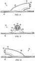
- FIGS. 4, 5 & 6show side, and end views of the reduced pressure adapter 22.
- Reduced pressure adapter 22as seen in the side view shown in FIG. 4 , is of low profile construction with base 50 defining its lateral limits. As indicated above, base 50 may be directly adhered to the distribution manifold or may be positioned and adhered using the drape of the wound dressing.
- the reduced pressure adapter 22is positioned on distribution manifold such that the aperture 53 (not seen in this view) of base 50 is in direct contact with the distribution manifold.
- primary lumen interface 64extends centrally out from conduit housing 62 and is surrounded by aperture 66. Conduits extend through the material of reduced pressure adapter 22 between the tubing interfaces and recessed region 54, as described above.
- the elbow region 68redirects fluid flow from the wound dressing positioned beneath reduced pressure adapter 22 to an angle associated with interface 64 in a manner that allows the system to be placed on the wound dressing and be maintained close to the wound dressing surface.
- FIG. 5is an end view of the same structure shown in FIG. 4 with the configuration of elbow region 68 and the internal configuration of conduit housing 62 more clearly shown. In this view, the same components associated with adhering reduced pressure adapter 22 to the wound dressing are disclosed. Base 50 and aperture 54 are positioned as indicated in FIG. 4 . Conduit housing 62 is shown as it would be positioned to receive a section of tubing for connection to the balance of the system of the present invention.
- conduit housing 62Internal to conduit housing 62 are primary lumen interface 64 and ancillary lumen interfaces 48 and 49.
- Ancillary lumen interfaces 48 and 49align with the corresponding lumens in the delivery tubing by placing the primary lumen in the tubing over the primary lumen interface 64.
- FIG. 6provides essentially the same view of reduced pressure adapter 22 as that of FIG. 4 but from the opposite side. Structurally, the elements shown are the same as those shown and described with FIG. 4 , which is indicative of the lateral (and to an extent, radial) symmetry of the connector. Unless otherwise indicated, the materials used to construct the improved connector of the present invention may be selected from a number of materials known in the art that provide the necessary flexibility and comfort to the patient while maintaining sufficient rigidity or resilience to maintain the open lumens that are integral to the reduced pressure adapter function.
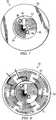
- FIG. 7provides a plan view (from below) of reduced pressure adapter 22 and clarifies the structure and function of the various features and elements within recessed region 54 that serve to preference liquids and other non-gaseous fluids away from the ancillary ports 56, 58.
- base 50is shown surrounding the edge of recessed region 54.
- Ancillary ports 56 and 58are shown positioned as indicated, with associated conduits extending internally from ports 56 and 58 to ancillary lumen interfaces (hidden and not shown in this view).
- Primary port 60can be seen centrally located within aperture 54.
- the primary conduitextends (hidden and not shown in this view) from primary port 60 through primary lumen interface 64.
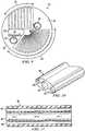
- FIG. 8shows an alternate exemplary embodiment of the base associated with the reduced pressure adapter of the present invention.
- features to the underside surface of alternate base 52are shown. These features, molded into the structure of base 52, include base serrated guide channels 70, perimeter collection channels 72, and intermediate collection channels 74. The objective of these channels is to direct liquid away from the two ancillary measurement ports 56, 58 and into the primary port 60.
- Base serrated guide channels 70are positioned and oriented on base 50 to directly capture and channel at least half of the liquids being drawn into the reduced pressure adapter, and indirectly channel a major portion of the balance of the liquids being drawn in.
- the spaced, radially-oriented arrangement of base serrated guide channels 70funnels liquids away from the ancillary ports and into the primary port.
- perimeter collection channels 72 and intermediate collection channels 74redirect the flow of liquids that are being drawn in between the radially-oriented guide channels 70 into the guide channels 70 and away from the ancillary ports.
- An example of this redirected flowis shown in FIG. 8 with bolded flow indication arrows.
- FIG. 9for a more detailed description of the features and elements contained within the recessed region of conduit housing 62. These features are positioned on the entry surface 55 of the recessed region 54 and are structured to preference liquids and other non-gaseous exudates away from the ancillary ports 56, 58 and into the primary port 60.
- primary port 60is shown centrally positioned within recessed region 54 and extending from the central location to one side of recessed region 54.
- Ancillary ports 56 and 58are likewise disclosed in this view, positioned to either side of the central location of primary port 60.
- ancillary ports 56 and 58are circular openings (each with raised circumferential edges) that extend toward a drainage point that opens into an internal conduit extending to the associated ancillary lumen interface (not shown). The openings of the conduits can be seen within the confines of ancillary ports 56 and 58.
- the first such structureis simply the placement of the ancillary ports 56 and 58 near the perimeter of the aperture 53 at a level that is close to the surface of the distribution manifold when the reduced pressure adapter 22 is positioned thereon.
- the ancillary ports 56 and 58are in contact, or are nearly in contact, with the surface of the distribution manifold. In this manner, the likelihood of splashed or agitated liquid being directed into these ports is minimized.
- a first linear serrated channel section 42is positioned in association with the approximately half circle section of recessed region 54 that is associated with ancillary port 58.
- the material that comprises the ceiling of this section of recessed region 54covers and contains the conduit that extends between ancillary port 58 and its interface (not shown).
- This ceiling or wallis configured with an array of serrated channels or striations that directs liquids that fall upon this surface towards the primary port at the center of the recessed region 54. Any liquids that are drawn into the opening and fall upon this portion of the entry surface 55 would be channeled directly into primary port 60, rather than being directed into ancillary port 58.
- a similar configurationis constructed in an approximately one-third circular radial serrated channel section 44.
- the serrated channels in section 44may extend deeper and more directly to the primary port 60.
- These radial serrated channelsare directed from the perimeter of aperture 54 towards the apex of the recessed region 54 that drains into primary port 60.
- These radial striations or channelsextend from a radius adjacent ancillary port 58 radially around approximately one-third of the circle to a radius adjacent ancillary port 56. Any liquids that fall upon this portion of the recessed region 54 will be directed centrally to primary port 60, rather than being conducted to either of the ancillary ports.
- the wall section that supports ancillary port 56 at the point at which the ancillary port 56 overhangs primary port 60is structured with serrated or striated channels 46 that extend downward (upward in the normal positioning of the connector) from the opening of ancillary port 56 towards the opening of primary port 60.
- the various internal features and elements of the recessed region 54are structured to draw liquid from most points within the recessed region 54 towards the centrally located primary port 60. Only liquid that enters directly into ancillary port 56 or 58 would likely be drawing into an ancillary lumen. Insofar as little or no suction is occurring at these ports, this structure greatly reduces the likelihood of obstructions in the form of liquid or material blockages in an ancillary lumen.
- the reduced pressure delivery tube 80preferably includes a primary central lumen 82 and ancillary lumens 84 and 86.
- Ancillary lumens 84 and 86are generally used for taking pressure measurements.
- fluid flow designated by the block arrowsis shown as it would be directed through primary lumen 82 while ancillary lumens 84 and 86 remain generally free of liquid or any non-gaseous matter.
- 10 and 11disclose the relative cross-sectional diameters of the primary lumen 82 as compared with the ancillary lumens 84 and 86.
- Delivery device 80has an oval cross-section, which optimizes flexibility without allowing for the collapse of any of the described lumens. This cross-sectional shape also orients the ancillary lumens 84 and 86 so that the lumens align appropriately with the interfaces on the improved reduced pressure adapter described above.
- the system of the present inventionalso includes an improved and dynamic method of measuring the wound pressure that overcomes problems inherent with current reduced pressure wound treatment control systems.
- Various methodshave been developed in the art to control the operation of reduced pressure wound treatment products and systems to insure that the wound pressure is maintained and that the therapy is safe by effective operation of the prescribed regimens.
- wound pressureis measured with the outer lumen or lumens of a multi-lumen tube that are commoned together and connected to one pressure sensor. This structure can suffer certain problems if liquid enters the lumens or they become blocked. If such liquid intrusion or blockages occur, the system can become unstable and alarms or indicators related to pressure become unreliable.
- Various mechanical remedies for these problemshave been attempted and some have been partially successful.
- One goal of the present inventionis a system that is more reliable and more robust when challenged with extremes of therapy, as compared to current single sensor measurement lumen systems.
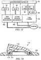
- FIG. 12wherein the system of an exemplary embodiment of the present invention and the functional relationship of its components are disclosed.
- the systemincorporates two wound pressure sensors 40a and 40b in the system instrumentation that extend separately (through discrete lumens or conduits) from the instrumentation to the reduced pressure adapter and are not commoned until the discrete lumens combine at the interface of the reduced pressure adapter and the distribution manifold.
- the reduced pressure adapterincorporates two separate pressure sensing ports as well as the fluid path through fluid chamber 18 to the reduced pressure pump 38 in the system instrumentation.
- each of the ancillary measurement lumen conduitsis fitted with a solenoid valve 92 and 94 which will relieve pressure to the wound at the end of therapy, during intermittent therapy, or if required to clear blockages.
- These valves, as well as a similar valve associated with the reduced pressure source 38,are controlled by microprocessor/controller 90.
- Microprocessor/controller 90likewise controls the operation of reduced pressure pump 38 and receives data from first and second pressure measurement devices 40a and 40b.
- the microprocessor/controller 90is programmed to monitor the wound pressure through the two readings associated with the two ancillary lumen paths. In instances where liquid enters one of the lumens, the liquid will cause a delay in the pressure change response time of that lumen versus the clear lumen.
- the reduced pressure adapter design of the present inventionis such as to maximize the chances of having at least one clear ancillary measurement lumen at any given time.
- reduced pressure adapters in RPWT systemstypically allow for the effective connection of reduced pressure wound therapy to the wound, but do not allow for the tube connection point to be repositioned (for example, in the event that the patient is susceptible to skin breakdown) or for a situation where the user has incorrectly positioned the reduced pressure adapter (for example, in the event that the reduced pressure adapter is facing in the wrong direction). In such instances, the user must remove and discard the reduced pressure adapter, and in some instances the drape, which causes discomfort and is a nuisance to the patient and user as well as an additional cost.
- Providing a rotation or swivel function to the reduced pressure adapterenables repositioning the tube without having to remove and relocate the reduced pressure adapter. This ability assists in any situation where the tubing requires relocation to avoid tissue damage.
- One goal of the present inventionis to provide a reduced pressure adapter structure that allows for easy relocation of the tubing without removing and relocating the reduced pressure adapter or the wound dressing.
- FIGS. 13 and 14show the various circular ring components that go together to make up the swivel connection of the present invention.
- a top rotating PVC component 112covers a top ABS insert ring 114 which itself is surrounded by a rubber o-ring 116.
- a bottom ABS insert ring 118is shown that holds o-ring 116 captive between it and the top ABS insert 114. Each of these rings is then fitted within the bottom PVC ring 120 which comes into contact with the base of the reduced pressure adapter and/or with the wound dressing itself.
- FIG. 14discloses the same components mentioned above as they would be assembled and thereby shows in clearer detail the manner in which the components interlock and rotate with or against each other.
- the captive o-ring 116is also shown to provide a proper seal for the internal reduced pressure chamber formed by the reduced pressure adapter 110.
- the internal features and elements in the port openingmay be appropriately positioned on the underside of top PVC component 112 to serve the function of preferencing liquid to the primary conduit as described above.
- One goal of the present inventionis to provide a system that will alert the caregiver to significant levels of key microorganisms under the classification of aerobic, non-aerobic, gram positive and gram negative.
- the response or indicationis in the form of color patterns discretely reflecting the four classifications mentioned above.
- a volatile organic compound (VOC) sensitive strip mounted on the reduced pressure adapter or its associated drapeis utilized in certain embodiments.
- VOCvolatile organic compound
- a color patternbecomes apparent and thereby identifies the type of microorganism present in the wound fluid.
- a reduced pressure adapter 122includes a base 124 and a conduit housing 130 similar to that described previously with reference to FIGS. 2-9 . The positioning of a VOC sensitive panel 128 in a recessed region 126 of the conduit housing 130 is shown. In FIG.
- the VOC sensitive panel 128can be visually inspected even from the exterior while the reduced pressure adapter 122 is in place with base 124 in position against the distribution manifold of the wound dressing.
- the preferable positioning of this VOC sensitive panel 128is therefore within the recessed region 126 near the periphery of the recessed region 126 as shown.
- FIG. 15shows more clearly the placement of this VOC sensitive panel within the recessed region 126 where it is constantly exposed to the fluid materials being drawn from the wound. Alternate placements of the panels are possible as long as sufficient exposure to wound fluids exists.
Landscapes
- Health & Medical Sciences (AREA)
- Heart & Thoracic Surgery (AREA)
- General Health & Medical Sciences (AREA)
- Engineering & Computer Science (AREA)
- Biomedical Technology (AREA)
- Life Sciences & Earth Sciences (AREA)
- Animal Behavior & Ethology (AREA)
- Public Health (AREA)
- Veterinary Medicine (AREA)
- Vascular Medicine (AREA)
- Anesthesiology (AREA)
- Hematology (AREA)
- External Artificial Organs (AREA)
- Media Introduction/Drainage Providing Device (AREA)
- Surgery (AREA)
Abstract
Description
- The present invention relates to generally to systems and methods for providing reduced pressure treatment to tissue, particularly open wounds. The present invention relates more specifically to systems and methods for improving the connection between a tissue dressing and reduced pressure source instrumentation used in conjunction with reduced pressure wound treatment (RPWT).
- Various therapies have been developed over time to facilitate the process of wound closure and healing. Wound closure generally involves the inward migration of epithelial and subcutaneous tissue adjacent the wound. This migration is ordinarily assisted by the inflammatory process, whereby blood flow is increased and various functional cell types are activated. As a result of the inflammatory process, blood flow through damaged or broken vessels is stopped by capillary level occlusion, whereafter cleanup and rebuilding operations may begin. Unfortunately, this process is hampered when a wound is large or has become infected. In such wounds, a zone of stasis (i.e. an area in which localized swelling of tissue restricts the flow of blood to the tissues) forms near the surface of the wound.
- Without sufficient blood flow, the epithelial and subcutaneous tissues surrounding the wound not only receive diminished oxygen and nutrients, but are also less able to successfully fight bacterial infection and, thus, less able to naturally close the wound. Additionally, some wounds harden and inflame to such a degree that closure by stapling or suturing is not feasible. Examples of wounds not readily treatable with staples or suturing include large, deep, open wounds; decubitus ulcers; ulcers resulting from chronic osteomyelitis; and partial thickness burns that subsequently develop into full thickness burns.
- As a result of the shortcomings of mechanical wound closure devices, methods and apparatus for draining wounds by applying continuous and/or periodic reduced pressures have been developed. When applied over a sufficient area of the wound, such reduced pressures have been found to promote the migration of epithelial and subcutaneous tissues toward the wound. In practice, the application to a wound of reduced pressure typically involves the mechanical-like contraction of the wound with simultaneous removal of excess fluid. In this manner, RPWT augments the body's natural inflammatory process while alleviating many of the known intrinsic side effects, such as the production of edema caused by increased blood flow absent the necessary vascular structure for proper venous return.
- Vacuum or reduced pressure induced healing of open wounds has recently been popularized by Kinetic Concepts, Inc. of San Antonio, Texas, through its commercially available RPWT systems product line. The reduced pressure induced healing process has been described in commonly assigned
U.S. Patent No. 4,969,880, issued on November 13, 1990 to Zamierowski , as well as in its related patents, includingU.S. Patent No. 5,100,396, issued on March 31, 1992 ;U.S. Patent No. 5,261,893, issued on November 16, 1993 ; andU.S. Patent No. 5,527,293 issued June 18, 1996 , the disclosures of which are each incorporated herein by reference. Further improvements and modifications of the RPWT process are also described inU.S. Patent No. 6,071,267, issued on June 6, 2000 to Zamierowski andU.S. Patents Nos. 5,636,643 and5,645,081 issued to Argenta et al . on June 10, 1997 and July 8, 1997 respectively, the disclosures of which are each incorporated by reference as though fully set forth herein. Additional improvements have also been described inU.S. Patent No. 6,142,982, issued on May 13, 1998 to Hunt, et al . - One important component of a RPWT system is the device or structure that connects the reduced pressure source (a vacuum pump, typically) to the components (a granular foam layer, typically) enclosed within the pad or wound dressing. This reduced pressure port structure must adhere to the wound dressing and be in fluid communication with the foam layer of the dressing. The port is preferably of low profile, in the nature of an attachment pad, in order to provide both comfort and safety to the patient. Various efforts have been made in the past to provide suitable adapter configurations to effectively connect the reduced pressure source (through tubing, typically) to a tissue site.
- Commensurate with the application of continuous and/or periodic reduced pressures to a wound is a coordinated monitoring of the pressure present at the tissue site as a result of the application of the RPWT system. It has become important, therefore, to provide systems that are capable of monitoring and responding to changes in the level of reduced pressure applied at the tissue site. Various regimens of RPWT that involve cycling the reduced pressure applied to the wound have been found to be beneficial under certain circumstances. Other situations benefit from a constant but closely regulated application of reduced pressure. In any case, it becomes valuable to accurately monitor the level of reduced pressure applied at the tissue site.
- Generally it is not possible to characterize the pressure level at the tissue site by simply measuring the level of reduced pressure that the reduced pressure source is providing, either at the source or in the conduit lines connecting the source to the wound dressing. Fluid flow within the primary lumen of tubing associated with RPWT systems prevents using pressure level measurements at the instrumentation from being accurate indicators of the level or stability of the pressure at the tissue site itself. Other methods for directly monitoring the wound pressure levels are therefore required.
- Some efforts have been made in the past to provide a separate pressure sensing or measurement conduit to the wound site connected to monitoring instrumentation. These efforts have typically provided a separate lumen within the RPWT tubing or have utilized a separate section of tubing altogether. The assumption being made with such systems, however, is that the ancillary measurement lumen or measurement tube is open and clear down to its port at the wound dressing. This is not always a valid assumption as, despite the fact that the measurement lumen is not forcibly drawing fluids in as is being done in the primary flow lumen of the RPWT system, it still collects fluids and other materials that inhibit or altogether block its function. The typically smaller cross-section of such measurement lumens may reduce the port size, and therefore the chance of fluid or other matter entering the port, but the same smaller cross-section results in even minor blockages becoming significant.
- Exemplary embodiments of the present invention provide improvements to the structure and use of the connector elements between the wound dressing and the reduced pressure source in a reduced pressure wound treatment (RPWT) system. More specifically certain exemplary embodiments provide:
- (A) A low profile reduced pressure adapter that improves the reliability of operation and prevents or reduces instances of unintentional fluid ingress into measurement lumens;
- (B) An improved reduced pressure delivery tube comprising an oval tubing structure with a larger inner lumen and smaller outer lumens for supporting the dynamic pressure functionality described below;
- (C) An improved and dynamic method of measuring wound pressure that overcomes certain problems with existing pressure control in RPWT systems;
- (D) An improved reduced pressure adapter structure having rotational functionality to facilitate the comfort of the attachment to the patient; and
- (E) A structure to provide indications of the presence of bacteria within the reduced pressure adapter and fluids transported therethrough.
- The improved reduced pressure adapter includes a conduit housing with a primary conduit and at least one secondary conduit for fluid connection to a wound dressing. The reduced pressure adapter also may include a base with a substantially circular shape. The conduit housing includes a recessed region defining an entry surface. The primary conduit connects the entry surface to a primary lumen of a multi-lumen reduced pressure delivery tube, and ancillary conduits connect the entry surface to ancillary lumens of the multi-lumen reduced pressure delivery tube. Channels positioned on the entry surface preferentially route liquids and other fluids into the primary conduit in order to prevent the clogging of the ancillary conduits, which are generally utilized to measure pressure within the wound dressing.
- The improved reduced pressure delivery tube incorporates a larger primary inner lumen to effect the conduction of reduced pressure to the tissue and fluids away from the tissue. Smaller outer ancillary lumens are provided to support the hereinafter described dynamic pressure functionality that insures the continuity of accurate pressure measurements through the monitoring of the open or closed (clogged) state of each of the ancillary lumens. The reduced pressure delivery tube may be mated to the improved reduced pressure adapter described above, or may be used with other adapters to fluidly connect a reduced pressure source and pressure sensors to a porous pad or other distribution manifold.
- The improved method of measuring pressure addresses certain problems with existing pressure control in RPWT systems that result from excessive fluid incursion into the measurement lumens of the system. Each of the ancillary lumens are monitored for their responsiveness to changes in the reduced pressure source (and thus in the wound dressing itself). A slow response in one of the ancillary lumens is indicative of clogging in that lumen, and as a result, the RPWT system considers the pressure measurement from the clear ancillary lumen as the accurate measurement. The system further allows for the introduction of elevated pressure into the clogged lumen in a manner that may serve to clear the lumen of fluid obstruction, all the while the second of the two ancillary lumens may continue to function as a monitoring channel for measuring the pressure at the tissue site.
- In other embodiments the improved reduced pressure adapter structure incorporates rotational functionality to improve the patient's convenience and comfort. The conduit housing is positioned on and rotatably attached to the perimeter base in a manner that allows the reduced pressure adapter and attached tubing to rotate with respect to the wound dressing thereby reducing strain on the dressing and the reduced pressure adapter.
- Finally, in a yet further embodiments, the improved reduced pressure adapter incorporates an internal surface, preferably formed on the interior perimeter wall of the conduit housing of the adapter, to provide indications of the presence of bacteria within the adapter enclosure and therefore the fluids transported through the adapter. This indicator surface retains a layer of material sensitive to the volatile organic compounds (VOC) associated with various targeted microorganisms. The VOC sensitive surface develops a specific color pattern depending on the type of VOC and therefore the type of microorganism present. The color pattern may be visually discerned through the clear material of the reduced pressure adapter construction or may be automatically detected by photometric color analysis using one of a variety of such photometric sensor devices.
- Finally, many other features, objects, and advantages of the present invention will be apparent to those of ordinary skill in the relevant arts, especially in light of the foregoing discussions and the following drawings and exemplary detailed description.
- Although the scope of the present invention is much broader than any particular embodiment, a detailed description of the preferred embodiment follows, together with illustrative figures, wherein like reference numerals refer to like components, and wherein:
FIG. 1 is a partially schematic, perspective view of the general arrangement of the components of a reduced pressure wound treatment (RPWT) system incorporating the improved elements of an exemplary embodiment of the present invention;FIG. 2 is a perspective view of the underside (open side) of an improved reduced pressure adapter according to an embodiment of the present invention;FIG. 3 is a plan view of the topside (closed side) of the improved reduced pressure adapter ofFIG. 2 ;FIG. 4 is a first side view of the improved reduced pressure adapter ofFIG. 2 ;FIG. 5 is an end view of the improved reduced pressure adapter ofFIG. 2 ;FIG. 6 is a second side view of the improved reduced pressure adapter ofFIG. 2 ;FIG. 7 is a plan view of the underside (open side) of the improved reduced pressure adapter ofFIG. 2 , the underside configured according to a first exemplary embodiment of the present invention;FIG. 8 is a plan view of the underside (open side) of the improved reduced pressure adapter ofFIG. 2 , the underside configured according to another exemplary embodiment of the present invention;FIG. 9 is a detailed view of a recessed region of the reduced pressure adapter ofFIGS. 7 and 8 ;FIG. 10 is a perspective view of an open end of an improved reduced pressure delivery tube according to an exemplary embodiment of the present invention;FIG. 11 is a longitudinal cross-sectional view of the improved reduced pressure delivery tube ofFIG. 10 ;FIG. 12 is a schematic block diagram illustrating the arrangement and functionality of a reduced pressure system according to an exemplary embodiment of the present invention;FIG. 13 is an exploded perspective view of an improved reduced pressure adapter according to an exemplary embodiment of the present invention, the reduced pressure adapter incorporating elements that provide rotational functionality;FIG. 14 is a cross-sectional view of the reduced pressure adapter ofFIG. 13 ;FIG. 15 is a bottom perspective view of a reduced pressure adapter having panels sensitive to the presence of microorganisms according to an exemplary embodiment of the present invention; andFIG. 16 is a side view of the reduced pressure adapter ofFIG. 15 in which the panels are visible through transparent or translucent side walls of the reduced pressure adapter.- In the following detailed description of the preferred embodiments, reference is made to the accompanying drawings that form a part hereof, and in which is shown by way of illustration specific preferred embodiments in which the invention may be practiced. These embodiments are described in sufficient detail to enable those skilled in the art to practice the invention, and it is understood that other embodiments may be utilized and that logical structural, mechanical, electrical, and chemical changes may be made without departing from the spirit or scope of the invention. To avoid detail not necessary to enable those skilled in the art to practice the invention, the description may omit certain information known to those skilled in the art. The following detailed description is, therefore, not to be taken in a limiting sense, and the scope of the present invention is defined only by the appended claims.
- Improvements in an RPWT system are disclosed that provide a reduced pressure adapter to improve the reliability of operation and prevent or reduce instances of unintentional liquid ingress into the measurement lumens of a reduced pressure delivery tube, particularly in conjunction with a low-profile dressing. Traditional adapters typically include both a sensing lumen and a reduced pressure delivery lumen together an elbow-shaped housing. A common cause of failure for these reduced pressure adapters results from liquid ingress into the sensing lumen, which may cause the control of therapy to become unstable and, in extreme cases, may contribute to the eventual shutdown of the device. Part of this problem is due to the location of the fluid conduction and the nature of wound fluid in general. Wound excretions and fluids are generally pseudoplastic in consistency and will splash and foam in the elbow of a reduced pressure apparatus under the influence of reduced pressure. One goal of certain exemplary embodiments of the present invention, therefore, is to prevent the wound liquids and other non-gaseous fluids from entering the sensing lumen.
- One concept of the improved reduced pressure adapter is for the lumens to be separate down to the distribution manifold of the wound dressing so that the distribution manifold becomes the barrier between the sensing lumens and the reduced pressure path. The underside of the reduced pressure adapter is provided with channel features that attract small droplets splashed inside the reduced pressure adapter during periods of high flow or after a large slug of liquid has been pulled into the tubing. This preferencing of the liquid and solid matter into the larger primary lumen, and away from the smaller ancillary measurement lumens, helps prevent the lumens from becoming blocked. The concept further includes providing offset outer measurement lumen ports in the pad, which are designed such that in most orientations one of the two should be above the flow level in the distribution manifold of the dressing. The reduced pressure adapter is further intended to operate in conjunction with the dynamic pressure control methodologies described in more detail below. The reduced pressure adapter may also include an adhesive drape or cover that secures the reduced pressure adapter within the wound. The profile of the reduced pressure adapter is low for increased patient comfort, and the reduced pressure adapter is preferably elbow-shaped such that the connecting tubing is routed cleanly away from the tissue site.
- Reference is made first to
FIG. 1 for a general description of the components included in a reduced pressure wound treatment (RPWT) system incorporating the improved elements of an exemplary embodiment of the present invention. The three primary components ofRPWT system 10 include wound dressing 12, reducedpressure delivery tube 14, and remote fluid containment andinstrumentation 16. - Wound dressing 12 is generally comprised of a
distribution manifold 24 such as a porous pad or granular foam and a cover or drape 26 that secures the distribution manifold at a tissue site.Dressing 12 also may include improved reducedpressure adapter 22, as shown positioned ondistribution manifold 24 and adhered thereto by an adhesive positioned on the reducedpressure adapter 22, thewound drape 26, or a separate adhesive drape associated with reducedpressure adapter 22. - Reduced
pressure delivery tube 14 is a multi-lumen tube, comprised of one ormore tubing sections 28 which, as an assembled structure, provide a continuous conduit between reducedpressure adapter 22 andcontainer connector 34 positioned onfluid container 18. As described in more detail below, and as known in the art, liquid and other exudates drawn byRPWT system 10 are removed from the tubing at this point and are retained withincontainer 18. Sections of additional tubing in the form of instrumentation tubing 36a and 36b likewise extend fromcontainer connector 34 toinstrumentation components 20. In certain embodiments of the present invention,instrumentation components 20 comprise a reducedpressure source 38 and pressuremonitoring instrument components instrument components 20 is individually associated with one of three isolated conduits (tubes or lumens) that extend from reducedpressure adapter 22 into remote fluid containment andinstrumentation 16. - Reference is now made to
FIGS. 2 - 9 for a more detailed description of the reducedpressure adapter 22.FIG. 2 provides a perspective view of the underside of reducedpressure adapter 22 showing the various structural elements within the opening of reducedpressure adapter 22 that are adapted to contact the distribution manifold 24 (not shown) of the wound dressing. Reduced pressure adapter 22 generally comprises abase 50, which may be adhered to the distribution manifold, and aconduit housing 62 coupled to thebase 50.Conduit housing 62 includes a primary conduit and a pair of ancillary conduits. Thebase 50 includes anaperture 53, which is positioned over the distribution manifold and through which the liquids and gases (collectively referred to as "fluids") are drawn from the tissue site. A significant feature of improved reducedpressure adapter 22 is the presence of channel elements positioned near and in fluid communication withaperture 53 and the effective way in which the channel elements direct liquid into the primary conduit for drainage. The routing of liquids into the primary conduit maintains the ancillary conduits of the system open for pressure measurement purposes.- Referring to
FIG. 2 , theconduit housing 62 of reducedpressure adapter 22 includes a recessedregion 54 defining anentry surface 55. The primary conduit terminates on theentry surface 55 at aprimary port 60, which is centrally located at an apex of the recessedregion 54. The ancillary conduits terminate on theentry surface 55 atancillary ports aperture 53. - A second end of the primary conduit terminates at a
primary lumen interface 64.Primary lumen interface 64 is generally centrally positioned withinaperture 66. Ancillary lumen interfaces 48, 49 (seeFIG. 5 ) to the ancillary conduits also are located withinaperture 66 and are described in more detail below. FIG. 3 provides a plan view (from above) of reducedpressure adapter 22. Theconduit housing 62 is preferably "elbow" shaped; however, the conduit housing may be configured at any desired angle or may extend perpendicularly frombase 50. In the elbow configuration illustrated inFIG. 3 , reducedpressure adapter 22 is seen to comprisebase 50 and a centrally positionedconduit housing 62.Conduit housing 62 includes anelbow region 68, and theconduit housing 62 internally comprises conduits between theports FIGS. 4, 5 & 6 show side, and end views of the reducedpressure adapter 22.Reduced pressure adapter 22, as seen in the side view shown inFIG. 4 , is of low profile construction withbase 50 defining its lateral limits. As indicated above,base 50 may be directly adhered to the distribution manifold or may be positioned and adhered using the drape of the wound dressing. The reducedpressure adapter 22 is positioned on distribution manifold such that the aperture 53 (not seen in this view) ofbase 50 is in direct contact with the distribution manifold. In the view shown inFIG. 4 ,primary lumen interface 64 extends centrally out fromconduit housing 62 and is surrounded byaperture 66. Conduits extend through the material of reducedpressure adapter 22 between the tubing interfaces and recessedregion 54, as described above. Theelbow region 68 redirects fluid flow from the wound dressing positioned beneath reducedpressure adapter 22 to an angle associated withinterface 64 in a manner that allows the system to be placed on the wound dressing and be maintained close to the wound dressing surface.FIG. 5 is an end view of the same structure shown inFIG. 4 with the configuration ofelbow region 68 and the internal configuration ofconduit housing 62 more clearly shown. In this view, the same components associated with adhering reducedpressure adapter 22 to the wound dressing are disclosed.Base 50 andaperture 54 are positioned as indicated inFIG. 4 .Conduit housing 62 is shown as it would be positioned to receive a section of tubing for connection to the balance of the system of the present invention.- Internal to
conduit housing 62 areprimary lumen interface 64 and ancillary lumen interfaces 48 and 49. Ancillary lumen interfaces 48 and 49 align with the corresponding lumens in the delivery tubing by placing the primary lumen in the tubing over theprimary lumen interface 64. The structure of one embodiment of multi-lumen tubing used in conjunction with the improved reduced pressure adapter structure of the present invention is described in more detail below. FIG. 6 provides essentially the same view of reducedpressure adapter 22 as that ofFIG. 4 but from the opposite side. Structurally, the elements shown are the same as those shown and described withFIG. 4 , which is indicative of the lateral (and to an extent, radial) symmetry of the connector. Unless otherwise indicated, the materials used to construct the improved connector of the present invention may be selected from a number of materials known in the art that provide the necessary flexibility and comfort to the patient while maintaining sufficient rigidity or resilience to maintain the open lumens that are integral to the reduced pressure adapter function.FIG. 7 provides a plan view (from below) of reducedpressure adapter 22 and clarifies the structure and function of the various features and elements within recessedregion 54 that serve to preference liquids and other non-gaseous fluids away from theancillary ports base 50 is shown surrounding the edge of recessedregion 54.Ancillary ports ports Primary port 60 can be seen centrally located withinaperture 54. The primary conduit extends (hidden and not shown in this view) fromprimary port 60 throughprimary lumen interface 64. The specific structures within recessedregion 54 that serve to conduct liquid into the primary conduit, and thereby allow the ancillary conduits to remain unobstructed are described in more detail below with respect toFIG. 9 .FIG. 8 shows an alternate exemplary embodiment of the base associated with the reduced pressure adapter of the present invention. In this view (the same perspective as that ofFIG. 7 ) added features to the underside surface ofalternate base 52 are shown. These features, molded into the structure ofbase 52, include baseserrated guide channels 70,perimeter collection channels 72, andintermediate collection channels 74. The objective of these channels is to direct liquid away from the twoancillary measurement ports primary port 60. Baseserrated guide channels 70 are positioned and oriented onbase 50 to directly capture and channel at least half of the liquids being drawn into the reduced pressure adapter, and indirectly channel a major portion of the balance of the liquids being drawn in. The spaced, radially-oriented arrangement of baseserrated guide channels 70 funnels liquids away from the ancillary ports and into the primary port. In addition,perimeter collection channels 72 andintermediate collection channels 74 redirect the flow of liquids that are being drawn in between the radially-orientedguide channels 70 into theguide channels 70 and away from the ancillary ports. An example of this redirected flow is shown inFIG. 8 with bolded flow indication arrows.- Reference is now made to
FIG. 9 for a more detailed description of the features and elements contained within the recessed region ofconduit housing 62. These features are positioned on theentry surface 55 of the recessedregion 54 and are structured to preference liquids and other non-gaseous exudates away from theancillary ports primary port 60. In this view,primary port 60 is shown centrally positioned within recessedregion 54 and extending from the central location to one side of recessedregion 54.Ancillary ports primary port 60. In this view,ancillary ports ancillary ports - Four basic features within the structure shown in
FIG. 9 are positioned to preference liquid into theprimary port 60 of the reducedpressure adapter 22. The first such structure is simply the placement of theancillary ports aperture 53 at a level that is close to the surface of the distribution manifold when the reducedpressure adapter 22 is positioned thereon. In other words, when the reducedpressure adapter 22 is positioned on the wound dressing, theancillary ports - The remaining three features that direct liquids into the primary port are structural serrated channels formed on various portions of the
entry surface 55 of recessedregion 54. A first linearserrated channel section 42 is positioned in association with the approximately half circle section of recessedregion 54 that is associated withancillary port 58. The material that comprises the ceiling of this section of recessedregion 54 covers and contains the conduit that extends betweenancillary port 58 and its interface (not shown). This ceiling or wall is configured with an array of serrated channels or striations that directs liquids that fall upon this surface towards the primary port at the center of the recessedregion 54. Any liquids that are drawn into the opening and fall upon this portion of theentry surface 55 would be channeled directly intoprimary port 60, rather than being directed intoancillary port 58. - A similar configuration is constructed in an approximately one-third circular radial
serrated channel section 44. Insofar as no internal conduit is contained within this section of the recessedregion 54, the serrated channels insection 44 may extend deeper and more directly to theprimary port 60. These radial serrated channels are directed from the perimeter ofaperture 54 towards the apex of the recessedregion 54 that drains intoprimary port 60. These radial striations or channels extend from a radius adjacentancillary port 58 radially around approximately one-third of the circle to a radius adjacentancillary port 56. Any liquids that fall upon this portion of the recessedregion 54 will be directed centrally toprimary port 60, rather than being conducted to either of the ancillary ports. - Finally, the wall section that supports
ancillary port 56 at the point at which theancillary port 56 overhangsprimary port 60 is structured with serrated orstriated channels 46 that extend downward (upward in the normal positioning of the connector) from the opening ofancillary port 56 towards the opening ofprimary port 60. - As described above, the various internal features and elements of the recessed
region 54 are structured to draw liquid from most points within the recessedregion 54 towards the centrally locatedprimary port 60. Only liquid that enters directly intoancillary port - Reference is now made to
FIGS. 10 and 11 for a detailed description of the structure of an improved reducedpressure delivery tube 80 operable in association with the system of an exemplary embodiment of the present invention. The reducedpressure delivery tube 80 preferably includes a primarycentral lumen 82 andancillary lumens Ancillary lumens FIG. 11 , fluid flow designated by the block arrows is shown as it would be directed throughprimary lumen 82 whileancillary lumens FIGS. 10 and 11 disclose the relative cross-sectional diameters of theprimary lumen 82 as compared with theancillary lumens Delivery device 80 has an oval cross-section, which optimizes flexibility without allowing for the collapse of any of the described lumens. This cross-sectional shape also orients theancillary lumens - The system of the present invention also includes an improved and dynamic method of measuring the wound pressure that overcomes problems inherent with current reduced pressure wound treatment control systems. Various methods have been developed in the art to control the operation of reduced pressure wound treatment products and systems to insure that the wound pressure is maintained and that the therapy is safe by effective operation of the prescribed regimens. Currently, wound pressure is measured with the outer lumen or lumens of a multi-lumen tube that are commoned together and connected to one pressure sensor. This structure can suffer certain problems if liquid enters the lumens or they become blocked. If such liquid intrusion or blockages occur, the system can become unstable and alarms or indicators related to pressure become unreliable. Various mechanical remedies for these problems have been attempted and some have been partially successful. Ultimately, however, a system such as described in the prior art will be challenged with liquid in the control lumen unless there is a physical barrier placed against the ingress of liquid into the measurement lumen(s). One goal of the present invention is a system that is more reliable and more robust when challenged with extremes of therapy, as compared to current single sensor measurement lumen systems.
- Reference is made to
FIG. 12 wherein the system of an exemplary embodiment of the present invention and the functional relationship of its components are disclosed. The system incorporates twowound pressure sensors fluid chamber 18 to the reducedpressure pump 38 in the system instrumentation. Inside the system instrumentation, each of the ancillary measurement lumen conduits is fitted with asolenoid valve pressure source 38, are controlled by microprocessor/controller 90. Microprocessor/controller 90 likewise controls the operation of reducedpressure pump 38 and receives data from first and secondpressure measurement devices controller 90 is programmed to monitor the wound pressure through the two readings associated with the two ancillary lumen paths. In instances where liquid enters one of the lumens, the liquid will cause a delay in the pressure change response time of that lumen versus the clear lumen. As the blockage becomes more acute so will the delay. When a delay is detected, the system will control the wound pressure according to that of the open lumen and will try to clear the liquid from the blocked lumen by opening the appropriate valve to atmosphere. The preferred programming will try to clear the blockage in this manner several times. If the system is not successful in clearing the blockage, the programming will, from that point on, ignore the affected lumen and control the system with the remaining clear lumen. The reduced pressure adapter design of the present invention, as described above, is such as to maximize the chances of having at least one clear ancillary measurement lumen at any given time. - Currently, reduced pressure adapters in RPWT systems typically allow for the effective connection of reduced pressure wound therapy to the wound, but do not allow for the tube connection point to be repositioned (for example, in the event that the patient is susceptible to skin breakdown) or for a situation where the user has incorrectly positioned the reduced pressure adapter (for example, in the event that the reduced pressure adapter is facing in the wrong direction). In such instances, the user must remove and discard the reduced pressure adapter, and in some instances the drape, which causes discomfort and is a nuisance to the patient and user as well as an additional cost. Providing a rotation or swivel function to the reduced pressure adapter enables repositioning the tube without having to remove and relocate the reduced pressure adapter. This ability assists in any situation where the tubing requires relocation to avoid tissue damage. One goal of the present invention is to provide a reduced pressure adapter structure that allows for easy relocation of the tubing without removing and relocating the reduced pressure adapter or the wound dressing.
- Reference is made to
FIGS. 13 and14 for a description of the configuration of an alternate preferred embodiment of the reduced pressure adapter structure. The reducedpressure adapter 110 shown inFIG. 13 employs a hard plastic inner core that forms a bearing surface to enable a rubber o-ring to seal against it and also to enable the bearing surface to slide past with relatively low friction. Bonded to the hard plastic inner core is a soft thermoplastic or elastomeric polymer that acts as a protective and cushioning cover.FIGS. 13 and14 show the various circular ring components that go together to make up the swivel connection of the present invention. A toprotating PVC component 112 covers a topABS insert ring 114 which itself is surrounded by a rubber o-ring 116. A bottomABS insert ring 118 is shown that holds o-ring 116 captive between it and thetop ABS insert 114. Each of these rings is then fitted within thebottom PVC ring 120 which comes into contact with the base of the reduced pressure adapter and/or with the wound dressing itself. - The internal features and elements associated with the reduced pressure adapter as described above in conjunction with a non-rotating embodiment are equally applicable here and may be integrated into the inside structure of top
rotating PVC component 112 by direct molding of the component or by positioning a molded insert into a shell to forrotating component 112. In any event, the same benefits of the liquid preferencing structures surrounding the lumen ports described above are obtainable with the rotating functionality of the alternate embodiment described. FIG. 14 discloses the same components mentioned above as they would be assembled and thereby shows in clearer detail the manner in which the components interlock and rotate with or against each other. In this view, the captive o-ring 116 is also shown to provide a proper seal for the internal reduced pressure chamber formed by the reducedpressure adapter 110. In this view it is also clear how the internal features and elements in the port opening may be appropriately positioned on the underside oftop PVC component 112 to serve the function of preferencing liquid to the primary conduit as described above.- Current reduced pressure treatment systems do not generally alert the caregiver to the presence of microorganisms in wound dressings. Many of these microorganisms can be significant factors in controlling infection at the wound site. One goal of the present invention is to provide a system that will alert the caregiver to significant levels of key microorganisms under the classification of aerobic, non-aerobic, gram positive and gram negative. The response or indication is in the form of color patterns discretely reflecting the four classifications mentioned above.
- A volatile organic compound (VOC) sensitive strip mounted on the reduced pressure adapter or its associated drape is utilized in certain embodiments. When exposed to the targeted VOC known to form in the presence of certain microorganisms, a color pattern becomes apparent and thereby identifies the type of microorganism present in the wound fluid. Referencing
FIGS. 15 and 16 , a reducedpressure adapter 122 includes abase 124 and aconduit housing 130 similar to that described previously with reference toFIGS. 2-9 . The positioning of a VOCsensitive panel 128 in a recessedregion 126 of theconduit housing 130 is shown. InFIG. 16 , it can be seen that given the translucent or transparent character of the material from which the reducedpressure adapter 122 is constructed, the VOCsensitive panel 128 can be visually inspected even from the exterior while the reducedpressure adapter 122 is in place withbase 124 in position against the distribution manifold of the wound dressing. The preferable positioning of this VOCsensitive panel 128 is therefore within the recessedregion 126 near the periphery of the recessedregion 126 as shown.FIG. 15 shows more clearly the placement of this VOC sensitive panel within the recessedregion 126 where it is constantly exposed to the fluid materials being drawn from the wound. Alternate placements of the panels are possible as long as sufficient exposure to wound fluids exists. - It should be apparent from the foregoing that an invention having significant advantages has been provided. While the invention is shown in only a few of its forms, it is not just limited but is susceptible to various changes and modifications without departing from the spirit thereof.
Aspects of the invention are disclosed in the following numbered clauses: - 1. A reduced pressure adapter for connecting a reduced pressure source to a porous pad, the adapter comprising:
- a conduit housing having a recessed region defining an entry surface;
a primary conduit through the conduit housing in fluid communication with a primary port on the entry surface; - at least one ancillary conduit through the conduit housing in fluid communication with an ancillary port on the entry surface; and
channels positioned on the entry surface to direct liquid away from the ancillary port and into the primary port.
- a conduit housing having a recessed region defining an entry surface;
- 2. The adapter of clause 1, further comprising:
- a base attached to the conduit housing such that an aperture of the base surrounds the recessed region.
- 3. The adapter of clause 2, wherein the conduit housing is rotatable about the base.
- 4. The adapter of clause 1, further comprising:
- a base attached to the conduit housing such that an aperture of the base surrounds the recessed region; and
- radial channels positioned on the base to direct liquid from a periphery of the base away from the ancillary conduit.
- 5. The adapter of clause 1 , further comprising:
- a base attached to the conduit housing such that an aperture of the base surrounds the recessed region;
- radial channels positioned on the base to direct liquid from a periphery of the base away from the ancillary conduit; and
- an intermediate collection channel positioned on the base to direct liquid into the radial guide channels.
- 6. The adapter of clause 1, wherein the channels comprise:
- a linear channel section along approximately half of the entry surface; and a radial channel section along approximately one-third of the entry surface.
- 7. The adapter of clause 1, further comprising an oval reduced pressure delivery tube having a primary lumen fluidly connected to the primary conduit and an ancillary lumen fluidly connected to the ancillary conduit.
- 8. The adapter of clause 1, further comprising a volatile organic compound sensitive strip mounted within the recessed region.
- 9. The adapter of clause 1, wherein there are at least two ancillary conduits having diametrically opposite ancillary ports on the entry surface.
- 10. The adapter of clause 1, further comprising a wall section supporting and surrounding the ancillary conduit, the wall section having an inside surface, an outside surface, and guide channels along the outside surface extending toward the primary port.
- 11. A system for applying reduced pressure to tissue, the system comprising:
- a multi-lumen reduced pressure delivery tube having a proximate end, a distal end, a primary lumen extending through the conduit from the proximate end to the distal end, and an ancillary lumen extending through the conduit from the proximate end to the distal end;
- a vacuum pump coupled to the proximate end of the primary lumen; and
- a reduced pressure adapter coupled to the distal end of the reduced pressure delivery tube, the adapter having channels to direct liquid away from the ancillary lumens and into the primary lumen.
- 12. The system of clause 11, wherein the reduced pressure adapter comprises:
- a conduit housing having an recessed region defining an entry surface;
- a primary conduit through the conduit housing in fluid communication with the primary lumen and a primary port on the entry surface;
- an ancillary conduit through the conduit housing in fluid communication with the ancillary lumen and an ancillary port on the entry surface; and
- wherein the channels are positioned on the entry surface to direct liquid away from the ancillary port and to the primary port.
- 13. The system of clause 11, further comprising a base attached to the conduit housing.
- 14. The system of clause 13, wherein the conduit housing is rotatable about the base.
- 15. The system of clause 13, wherein:
- the conduit housing is rotatable about the base; and
- the ancillary port is positioned substantially flush with the base.
- 16. The system of
clause 12, further comprising:- a base attached to the conduit housing; and
- radial guide channels positioned on the base to direct liquid from a periphery of the base away from the ancillary port.
- 17. The system of
clause 12, further comprising:- a pressure sensor coupled to the proximate end of the ancillary lumen;
- a valve coupled to the ancillary lumen; and
- a controller coupled to the pressure sensor, the valve, and the vacuum pump, the controller programmed to:
- operate the vacuum pump to reduce pressure in the primary lumen;
- receive pressure data from the pressure sensor, monitor changes in the pressure data in response to associated changes to the vacuum pump operation;
- identify if the ancillary lumen has a delayed pressure response; and operate the valve coupled to the identified ancillary lumen.
- 18. A method for monitoring a pressure applied to a tissue site, the method comprising:
- measuring pressure through at least two pressure measurement conduits having openings near the tissue site, said measurement conduits isolated from each other and from a primary conduit;
- monitoring a response time associated with changes in pressure measured through the pressure measurement conduits when changes in pressure are applied through the primary conduit; and
- opening one or more of the pressure measurement conduits to a pressure greater than the applied pressure if the response time associated with the pressure measurement conduits indicates a delayed response.
- 19. A rotatable reduced pressure adapter for connecting a reduced pressure source to a porous pad, the adapter comprising:
- a base;
- a perimeter ring attached to the base;
- an first insert ring within the perimeter ring;
- an o-ring within the first insert ring;
- a second insert ring within the o-ring; and
- a housing covering the second insert ring.
- 20. The connector of clause 19, wherein the housing includes a recessed region defining an entry surface.
- 21. The connector of
clause 20, further comprising: a primary conduit through the housing in fluid communication with a primary port on the entry surface;
at least one ancillary conduit in fluid communication with an ancillary port on the entry surface; and
channels positioned on the entry surface to direct liquid away from the ancillary port and to the primary port. - 22. A system for applying reduced pressure to a tissue site, the system comprising:
- a multi-lumen reduced pressure delivery tube having an oval cross-section, a proximate end, a distal end, a primary lumen extending through the conduit from the proximate end to the distal end, and a plurality of ancillary lumens extending through the conduit from the proximate end to the distal end;
- a vacuum pump coupled to the proximate end of the primary lumen; and a reduced pressure adapter coupled to the distal end, the adapter comprising: a conduit housing having a recessed region defining an entry surface;
- a primary conduit positioned within the conduit housing and terminating at a primary port centrally positioned on the entry surface;
- ancillary conduits positioned adjacent to the primary conduit and terminating at ancillary ports located on the entry surface;
- a linear serrated channel section along approximately half of the entry surface;
- a radial serrated channel section along approximately one-third of the entry surface;
- a base attached to the conduit housing;
- radial guide channels positioned on the base to direct liquid from a periphery of the base away from the ancillary ports;
- an intermediate collection channel positioned on the base to direct liquid into the radial guide channels; and
- a volatile organic compound sensitive strip mounted within the recessed region.
- 23. A reduced pressure adapter comprising:
- a conduit housing having a recessed region for receiving a liquid from a tissue site;
- means for fluidly connecting the recessed region to a primary lumen and an ancillary lumen; and
- means for directing the liquid away from the ancillary lumen and to the primary lumen.
- 24. The adapter of clause 23, further comprising:
- a base connected to the conduit housing; and
- means for rotating the conduit housing about the base.
- 25. A system for applying reduced pressure to a tissue site, the system comprising:
- a multi-lumen conduit having a proximate end, a distal end, a primary lumen extending through the conduit from the proximate end to the distal end, and ancillary lumens extending through the conduit from the proximate end to the distal end;
- a vacuum pump coupled to the proximate end of the primary lumen;
- a reduced pressure adapter coupled to the distal end, the adapter having channels to direct liquid into the primary lumen; and
- means for operating the vacuum pump using feedback from at least two pressure sensors coupled to the ancillary lumens.
- 26. A multi-lumen reduced pressure delivery apparatus comprising:
- a flexible tube having a first end, a second end, and an oval cross-section; a primary conduit extending from the first end to the second end; and an ancillary conduit extending from the first end to the second end adjacent to the primary conduit;
- wherein the primary conduit has a first diameter and the ancillary conduit has a second diameter substantially smaller than the first diameter.
- 27. A dressing for applying reduced pressure to a tissue site, the dressing comprising:
- a multi-lumen reduced pressure delivery tube having a proximate end, a distal end, a primary lumen extending through the conduit from the proximate end to the distal end, and ancillary lumens extending through the conduit from the proximate end to the distal end;
- a reduced pressure adapter coupled to the distal end, the adapter having channels to direct liquid away from the ancillary lumens and into the primary lumen;
- a porous pad attached to the reduced pressure adapter; and
- a drape placed over the reduced pressure adapter and the porous pad, the drape having an adhesive surface for securing the reduced pressure adapter and the porous pad at the tissue site.
Claims (12)
- A rotatable reduced pressure adapter for connecting a reduced pressure source to a porous pad, the adapter comprising:a perimeter ring (120);a first insert ring (118) within the perimeter ring (120);an o-ring (116) within the first insert ring (118);a second insert ring (114) within the o-ring (116); anda housing (112) covering the second insert ring (114).
- The connector of claim 1, wherein the housing (120) includes a recessed region defining an entry surface.
- The connector of claim 2, further comprising:a primary conduit through the housing (112) in fluid communication with a primary port on the entry surface;at least one ancillary conduit in fluid communication with an ancillary port on the entry surface; andchannels positioned on the entry surface to direct liquid away from the ancillary port and to the primary port.
- The connector of claim 1, wherein the housing (112) is rotatable relative to the perimeter ring (120).
- The connector of claim 1, further comprising a base, wherein the perimeter ring (120) is attached to the base.
- The connector of claim 3, wherein the channels are radial channels and are configured to direct liquid away from a periphery of the perimeter ring (120).
- The connector of claim 3, further comprising an intermediate collection channel positioned on the perimeter ring (120) to direct liquid into the radial channels.
- The connector of claim 3, wherein the channels comprise
a linear channel section along approximately half of the entry surface; and
a radial channel section along approximately one-third of the entry surface. - The connector of claim 3, further comprising a base, wherein the perimeter ring (120) is attached to the base.
- The connector of claim 9, wherein the channels are radial channels and are configured to direct liquid away from a periphery of the base.
- The connector of claim 9, further comprising an intermediate collection channel positioned on the base to direct liquid into the radial channels.
- The connector of claim 9, wherein the channels comprise
a linear channel section along approximately half of the entry surface; and
a radial channel section along approximately one-third of the entry surface.
Priority Applications (2)
| Application Number | Priority Date | Filing Date | Title |
|---|---|---|---|
| EP19152893.4AEP3533478B1 (en) | 2006-02-06 | 2007-02-06 | Systems for improved connection to wound dressings in conjunction with reduced pressure wound treatment |
| EP21186076.2AEP3932441B1 (en) | 2006-02-06 | 2007-02-06 | Systems for improved connection to wound dressings in conjunction with reduced pressure wound treatment |
Applications Claiming Priority (5)
| Application Number | Priority Date | Filing Date | Title |
|---|---|---|---|
| US76554806P | 2006-02-06 | 2006-02-06 | |
| US11/702,822US7651484B2 (en) | 2006-02-06 | 2007-02-06 | Systems and methods for improved connection to wound dressings in conjunction with reduced pressure wound treatment systems |
| EP15191747.3AEP3040091B1 (en) | 2006-02-06 | 2007-02-06 | Systems for improved connection to wound dressings in conjunction with reduced pressure wound treatment systems |
| PCT/US2007/003065WO2007092397A2 (en) | 2006-02-06 | 2007-02-06 | Systems and methods for improved connection to wound dressings in conjunction with reduced pressure wound treatment systems |
| EP07763376.6AEP1986718B1 (en) | 2006-02-06 | 2007-02-06 | Systems for improved connection to wound dressings in conjunction with reduced pressure wound treatment systems |
Related Parent Applications (3)
| Application Number | Title | Priority Date | Filing Date |
|---|---|---|---|
| EP15191747.3ADivisionEP3040091B1 (en) | 2006-02-06 | 2007-02-06 | Systems for improved connection to wound dressings in conjunction with reduced pressure wound treatment systems |
| EP15191747.3ADivision-IntoEP3040091B1 (en) | 2006-02-06 | 2007-02-06 | Systems for improved connection to wound dressings in conjunction with reduced pressure wound treatment systems |
| EP07763376.6ADivisionEP1986718B1 (en) | 2006-02-06 | 2007-02-06 | Systems for improved connection to wound dressings in conjunction with reduced pressure wound treatment systems |
Related Child Applications (3)
| Application Number | Title | Priority Date | Filing Date |
|---|---|---|---|
| EP21186076.2ADivisionEP3932441B1 (en) | 2006-02-06 | 2007-02-06 | Systems for improved connection to wound dressings in conjunction with reduced pressure wound treatment |
| EP19152893.4ADivisionEP3533478B1 (en) | 2006-02-06 | 2007-02-06 | Systems for improved connection to wound dressings in conjunction with reduced pressure wound treatment |
| EP19152893.4ADivision-IntoEP3533478B1 (en) | 2006-02-06 | 2007-02-06 | Systems for improved connection to wound dressings in conjunction with reduced pressure wound treatment |
Publications (2)
| Publication Number | Publication Date |
|---|---|
| EP3348290A1true EP3348290A1 (en) | 2018-07-18 |
| EP3348290B1 EP3348290B1 (en) | 2019-11-20 |
Family
ID=38345717
Family Applications (5)
| Application Number | Title | Priority Date | Filing Date |
|---|---|---|---|
| EP07763376.6AActiveEP1986718B1 (en) | 2006-02-06 | 2007-02-06 | Systems for improved connection to wound dressings in conjunction with reduced pressure wound treatment systems |
| EP18158692.6AActiveEP3348290B1 (en) | 2006-02-06 | 2007-02-06 | Systems for improved connection to wound dressings in conjunction with reduced pressure wound treatment systems |
| EP19152893.4AActiveEP3533478B1 (en) | 2006-02-06 | 2007-02-06 | Systems for improved connection to wound dressings in conjunction with reduced pressure wound treatment |
| EP15191747.3AActiveEP3040091B1 (en) | 2006-02-06 | 2007-02-06 | Systems for improved connection to wound dressings in conjunction with reduced pressure wound treatment systems |
| EP21186076.2AActiveEP3932441B1 (en) | 2006-02-06 | 2007-02-06 | Systems for improved connection to wound dressings in conjunction with reduced pressure wound treatment |
Family Applications Before (1)
| Application Number | Title | Priority Date | Filing Date |
|---|---|---|---|
| EP07763376.6AActiveEP1986718B1 (en) | 2006-02-06 | 2007-02-06 | Systems for improved connection to wound dressings in conjunction with reduced pressure wound treatment systems |
Family Applications After (3)
| Application Number | Title | Priority Date | Filing Date |
|---|---|---|---|
| EP19152893.4AActiveEP3533478B1 (en) | 2006-02-06 | 2007-02-06 | Systems for improved connection to wound dressings in conjunction with reduced pressure wound treatment |
| EP15191747.3AActiveEP3040091B1 (en) | 2006-02-06 | 2007-02-06 | Systems for improved connection to wound dressings in conjunction with reduced pressure wound treatment systems |
| EP21186076.2AActiveEP3932441B1 (en) | 2006-02-06 | 2007-02-06 | Systems for improved connection to wound dressings in conjunction with reduced pressure wound treatment |
Country Status (13)
| Country | Link |
|---|---|
| US (7) | US7651484B2 (en) |
| EP (5) | EP1986718B1 (en) |
| JP (1) | JP4719278B2 (en) |
| KR (1) | KR101045751B1 (en) |
| CN (2) | CN101378796B (en) |
| AU (2) | AU2007212480B2 (en) |
| BR (1) | BRPI0706893B8 (en) |
| CA (1) | CA2635617C (en) |
| IL (1) | IL193142A0 (en) |
| MX (1) | MX2008009755A (en) |
| RU (2) | RU2436597C2 (en) |
| WO (1) | WO2007092397A2 (en) |
| ZA (1) | ZA200807411B (en) |
Families Citing this family (235)
| Publication number | Priority date | Publication date | Assignee | Title |
|---|---|---|---|---|
| GB9523253D0 (en)* | 1995-11-14 | 1996-01-17 | Mediscus Prod Ltd | Portable wound treatment apparatus |
| GB9719520D0 (en) | 1997-09-12 | 1997-11-19 | Kci Medical Ltd | Surgical drape and suction heads for wound treatment |
| CN1822874B (en) | 2003-07-22 | 2010-10-13 | 凯希特许有限公司 | Negative pressure wound treatment dressing |
| US11298453B2 (en) | 2003-10-28 | 2022-04-12 | Smith & Nephew Plc | Apparatus and method for wound cleansing with actives |
| GB0508531D0 (en) | 2005-04-27 | 2005-06-01 | Smith & Nephew | Sai with ultrasound |
| SE0500061L (en) | 2005-01-11 | 2006-07-12 | Moelnlycke Health Care Ab | Sealing film dressing |
| CA2619925A1 (en) | 2005-09-07 | 2007-03-15 | Tyco Healthcare Group Lp | Wound dressing with vacuum reservoir |
| EP1986718B1 (en) | 2006-02-06 | 2015-10-28 | KCI Licensing, Inc. | Systems for improved connection to wound dressings in conjunction with reduced pressure wound treatment systems |
| SE0601536L (en)* | 2006-07-11 | 2008-01-12 | Moelnlycke Health Care Ab | Coil connection |
| GB0712735D0 (en)* | 2006-07-26 | 2007-08-08 | Smith & Nephew | Dressing |
| US9820888B2 (en) | 2006-09-26 | 2017-11-21 | Smith & Nephew, Inc. | Wound dressing |
| EP1905465B2 (en) | 2006-09-28 | 2013-11-27 | Smith & Nephew, Inc. | Portable wound therapy system |
| US7967810B2 (en) | 2006-10-20 | 2011-06-28 | Mary Beth Kelley | Sub-atmospheric wound-care system |
| CA2674997C (en) | 2007-02-09 | 2012-08-14 | Kci Licensing, Inc. | A breathable interface system for topical reduced pressure |
| EP2129409B2 (en) | 2007-03-14 | 2021-11-24 | The Board of Trustees of the Leland Stanford Junior University | Devices for application of reduced pressure therapy |
| CN101678156B (en) | 2007-05-10 | 2013-05-22 | 凯希特许有限公司 | Reduced pressure wound dressing having a wound contact surface with columnar protrusions |
| EP2203137B1 (en) | 2007-10-11 | 2016-02-24 | Spiracur, Inc. | Closed incision negative pressure wound therapy device |
| WO2009067711A2 (en)* | 2007-11-21 | 2009-05-28 | T.J. Smith & Nephew, Limited | Suction device and dressing |
| WO2009068666A2 (en)* | 2007-11-30 | 2009-06-04 | Coloplast A/S | Attachment device for wound drainage system |
| WO2009068665A1 (en)* | 2007-11-30 | 2009-06-04 | Coloplast A/S | Tube assembly for use in a wound drainage system |
| US11253399B2 (en) | 2007-12-06 | 2022-02-22 | Smith & Nephew Plc | Wound filling apparatuses and methods |
| GB0723852D0 (en)* | 2007-12-06 | 2008-01-16 | Smith & Nephew | Wound fillers |
| US20130096518A1 (en)* | 2007-12-06 | 2013-04-18 | Smith & Nephew Plc | Wound filling apparatuses and methods |
| GB0723872D0 (en) | 2007-12-06 | 2008-01-16 | Smith & Nephew | Apparatus for topical negative pressure therapy |
| GB0723874D0 (en)* | 2007-12-06 | 2008-01-16 | Smith & Nephew | Dressing |
| GB0723855D0 (en) | 2007-12-06 | 2008-01-16 | Smith & Nephew | Apparatus and method for wound volume measurement |
| GB2455962A (en) | 2007-12-24 | 2009-07-01 | Ethicon Inc | Reinforced adhesive backing sheet, for plaster |
| US8377017B2 (en)* | 2008-01-03 | 2013-02-19 | Kci Licensing, Inc. | Low-profile reduced pressure treatment system |
| US8366692B2 (en) | 2008-01-08 | 2013-02-05 | Richard Scott Weston | Sustained variable negative pressure wound treatment and method of controlling same |
| AU2009214439B2 (en)* | 2008-02-14 | 2014-09-25 | Solventum Intellectual Properties Company | Devices and methods for treatment of damaged tissue |
| AU2009221772B2 (en) | 2008-03-05 | 2015-01-22 | Solventum Intellectual Properties Company | Dressing and method for applying reduced pressure to and collecting and storing fluid from a tissue site |
| US8021347B2 (en) | 2008-07-21 | 2011-09-20 | Tyco Healthcare Group Lp | Thin film wound dressing |
| US8298200B2 (en) | 2009-06-01 | 2012-10-30 | Tyco Healthcare Group Lp | System for providing continual drainage in negative pressure wound therapy |
| US9033942B2 (en) | 2008-03-07 | 2015-05-19 | Smith & Nephew, Inc. | Wound dressing port and associated wound dressing |
| US20180369462A1 (en)* | 2008-03-07 | 2018-12-27 | Smith & Nephew, Inc. | System for providing wound dressing port and associated wound dressing |
| AU2009223037A1 (en) | 2008-03-12 | 2009-09-17 | Smith & Nephew Plc | Negative pressure dressing and method of using same |
| EP2977067B1 (en)* | 2008-03-13 | 2020-12-09 | 3M Innovative Properties Company | Apparatus for applying reduced pressure to a tissue site on a foot |
| BRPI0906527A2 (en) | 2008-04-04 | 2016-09-06 | 3Mm Innovative Properties Company | apparatus for applying bandages to wounds and medical bandages |
| GB0808376D0 (en) | 2008-05-08 | 2008-06-18 | Bristol Myers Squibb Co | Wound dressing |
| ES2658263T3 (en) | 2008-08-08 | 2018-03-09 | Smith & Nephew, Inc. | Continuous fiber wound dressing |
| GB0817796D0 (en) | 2008-09-29 | 2008-11-05 | Convatec Inc | wound dressing |
| US8158844B2 (en) | 2008-10-08 | 2012-04-17 | Kci Licensing, Inc. | Limited-access, reduced-pressure systems and methods |
| KR101028916B1 (en)* | 2008-11-12 | 2011-04-12 | 주식회사 대웅제약 | Medical Suction Device |
| CA2744548C (en)* | 2008-11-25 | 2017-06-13 | Spiracur Inc. | Device for delivery of reduced pressure to body surfaces |
| US8721629B2 (en)* | 2008-12-02 | 2014-05-13 | Kci Licensing, Inc. | System and method for mechanical closure of wounds |
| US8529528B2 (en) | 2008-12-24 | 2013-09-10 | Kci Licensing, Inc. | Reduced-pressure wound treatment systems and methods employing microstrain-inducing manifolds |
| US8708984B2 (en)* | 2008-12-24 | 2014-04-29 | Kci Licensing, Inc. | Reduced-pressure wound treatment systems and methods employing manifold structures |
| WO2010078118A2 (en) | 2008-12-30 | 2010-07-08 | Kci Licensing, Inc. | Reduced pressure augmentation of microfracture procedures for cartilage repair |
| TWI418374B (en)* | 2008-12-31 | 2013-12-11 | Ind Tech Res Inst | Wound treatment apparatus and guiding unit thereof |
| JP5628203B2 (en) | 2008-12-31 | 2014-11-19 | ケーシーアイ ライセンシング インコーポレイテッド | A system that induces fluid flow to stimulate tissue growth |
| CA2745462C (en) | 2008-12-31 | 2014-07-15 | Kci Licensing, Inc. | Tissue roll scaffolds |
| US8361043B2 (en) | 2009-01-07 | 2013-01-29 | Spiracur Inc. | Reduced pressure therapy of the sacral region |
| US8162907B2 (en) | 2009-01-20 | 2012-04-24 | Tyco Healthcare Group Lp | Method and apparatus for bridging from a dressing in negative pressure wound therapy |
| GB0902368D0 (en) | 2009-02-13 | 2009-04-01 | Smith & Nephew | Wound packing |
| GB0902816D0 (en) | 2009-02-19 | 2009-04-08 | Smith & Nephew | Fluid communication path |
| US8728045B2 (en)* | 2009-03-04 | 2014-05-20 | Spiracur Inc. | Devices and methods to apply alternating level of reduced pressure to tissue |
| JP5650199B2 (en) | 2009-04-10 | 2015-01-07 | スピレイカー・インコーポレイテッドSpiracur, Inc. | Method and apparatus for attaching a negative pressure closure therapy system for a closed incision |
| US8444614B2 (en) | 2009-04-10 | 2013-05-21 | Spiracur, Inc. | Methods and devices for applying closed incision negative pressure wound therapy |
| US8591485B2 (en)* | 2009-04-23 | 2013-11-26 | Prospera Technologies, LLC | System, method, and pump to prevent pump contamination during negative pressure wound therapy |
| SE533726C2 (en) | 2009-04-30 | 2010-12-14 | Moelnlycke Health Care Ab | Apparatus with negative pressure for treatment of wounds |
| US20100324516A1 (en) | 2009-06-18 | 2010-12-23 | Tyco Healthcare Group Lp | Apparatus for Vacuum Bridging and/or Exudate Collection |
| WO2011043863A2 (en)* | 2009-08-13 | 2011-04-14 | Michael Simms Shuler | Methods and dressing systems for promoting healing of injured tissue |
| US8690844B2 (en)* | 2009-08-27 | 2014-04-08 | Kci Licensing, Inc. | Re-epithelialization wound dressings and systems |
| US20110054420A1 (en)* | 2009-08-27 | 2011-03-03 | Christopher Brian Locke | Reduced-pressure wound dressings and systems for re-epithelialization and granulation |
| AU2010298770B2 (en) | 2009-09-22 | 2015-05-28 | Molnlycke Health Care Ab | An apparatus and method for controlling the negative pressure in a wound |
| KR101063342B1 (en)* | 2009-12-04 | 2011-09-07 | 주식회사 바이오알파 | Portable vacuum generator and medical suction device using same |
| AU2010341491B2 (en) | 2009-12-22 | 2015-05-14 | Smith & Nephew, Inc. | Apparatuses and methods for negative pressure wound therapy |
| DE102009060596A1 (en)* | 2009-12-23 | 2011-06-30 | Paul Hartmann Aktiengesellschaft, 89522 | Connection device for use in the vacuum treatment of wounds |
| WO2011090996A2 (en) | 2010-01-20 | 2011-07-28 | Kci Licensing, Inc. | Leak-resistant bandage systems and methods with hydrophilic foam wound insert for fluid-instillation and/or negative-pressure wound therapies |
| CN102712112B (en)* | 2010-01-20 | 2015-11-25 | 凯希特许有限公司 | There is the foam wound insert of higher and lower density regions, wound dressing and method |
| CA2784138C (en) | 2010-01-20 | 2018-04-24 | Kci Licensing, Inc. | Wound-connection pads for fluid instillation and negative pressure wound therapy, and systems and methods |
| EP2525842B1 (en) | 2010-01-22 | 2017-03-22 | KCI Licensing, Inc. | Devices, systems, and methods for instillation of foamed fluid with negative pressure wound therapy |
| US8394081B2 (en)* | 2010-01-29 | 2013-03-12 | Kci Licensing, Inc. | Wound treatment apparatuses and methods for controlled delivery of fluids to a wound |
| US8791315B2 (en) | 2010-02-26 | 2014-07-29 | Smith & Nephew, Inc. | Systems and methods for using negative pressure wound therapy to manage open abdominal wounds |
| US8469935B2 (en)* | 2010-03-11 | 2013-06-25 | Kci Licensing, Inc. | Abdominal treatment systems, delivery devices, and methods |
| US8814842B2 (en) | 2010-03-16 | 2014-08-26 | Kci Licensing, Inc. | Delivery-and-fluid-storage bridges for use with reduced-pressure systems |
| US8604265B2 (en)* | 2010-04-16 | 2013-12-10 | Kci Licensing, Inc. | Dressings and methods for treating a tissue site on a patient |
| GB201006986D0 (en)* | 2010-04-27 | 2010-06-09 | Smith & Nephew | Wound dressing |
| US9061095B2 (en) | 2010-04-27 | 2015-06-23 | Smith & Nephew Plc | Wound dressing and method of use |
| GB201006988D0 (en)* | 2010-04-27 | 2010-06-09 | Smith & Nephew | Suction port |
| USRE48117E1 (en) | 2010-05-07 | 2020-07-28 | Smith & Nephew, Inc. | Apparatuses and methods for negative pressure wound therapy |
| CN101829391A (en)* | 2010-05-16 | 2010-09-15 | 崇阳县天南星实业有限责任公司 | Medical drainage sucking disc and preparation method thereof |
| US20110306944A1 (en)* | 2010-06-14 | 2011-12-15 | Chean-Shui Chen | Milk collecting bottle for hand expression |
| GB201011173D0 (en) | 2010-07-02 | 2010-08-18 | Smith & Nephew | Provision of wound filler |
| EP2593153B1 (en)* | 2010-07-16 | 2016-11-02 | KCI Licensing, Inc. | System and method for interfacing with a reduced pressure dressing |
| US8753322B2 (en) | 2010-08-10 | 2014-06-17 | Spiracur Inc. | Controlled negative pressure apparatus and alarm mechanism |
| US8795246B2 (en) | 2010-08-10 | 2014-08-05 | Spiracur Inc. | Alarm system |
| GB201015656D0 (en) | 2010-09-20 | 2010-10-27 | Smith & Nephew | Pressure control apparatus |
| GB201020005D0 (en) | 2010-11-25 | 2011-01-12 | Smith & Nephew | Composition 1-1 |
| CA2819032C (en) | 2010-11-25 | 2020-06-23 | Smith & Nephew Plc | Composition i-ii and products and uses thereof |
| GB201020236D0 (en) | 2010-11-30 | 2011-01-12 | Convatec Technologies Inc | A composition for detecting biofilms on viable tissues |
| WO2012078724A1 (en) | 2010-12-08 | 2012-06-14 | Convatec Technologies Inc. | Apparatus and method for applying pressure to a wound site |
| US10207031B2 (en) | 2010-12-08 | 2019-02-19 | Convatec Technologies Inc. | Integrated system for assessing wound exudates |
| ES2748519T3 (en) | 2010-12-08 | 2020-03-17 | Convatec Technologies Inc | Wound exudate system accessory |
| USD714433S1 (en) | 2010-12-22 | 2014-09-30 | Smith & Nephew, Inc. | Suction adapter |
| RU2016111981A (en) | 2010-12-22 | 2018-11-27 | Смит Энд Нефью, Инк. | DEVICE AND METHOD FOR TREATING RAS WITH NEGATIVE PRESSURE |
| GB2488749A (en) | 2011-01-31 | 2012-09-12 | Systagenix Wound Man Ip Co Bv | Laminated silicone coated wound dressing |
| US9421132B2 (en) | 2011-02-04 | 2016-08-23 | University Of Massachusetts | Negative pressure wound closure device |
| AU2012212070A1 (en) | 2011-02-04 | 2013-09-19 | University Of Massachusetts | Negative pressure wound closure device |
| GB201106491D0 (en) | 2011-04-15 | 2011-06-01 | Systagenix Wound Man Ip Co Bv | Patterened silicone coating |
| WO2013066426A2 (en) | 2011-06-24 | 2013-05-10 | Kci Licensing, Inc. | Reduced-pressure dressings employing tissue-fixation elements |
| CN103764186B (en)* | 2011-07-26 | 2016-05-04 | 凯希特许有限公司 | Systems and methods for treating a tissue site with reduced pressure, involving a reduced-pressure interface having a multi-lumen catheter for contacting a manifold |
| GB201115182D0 (en) | 2011-09-02 | 2011-10-19 | Trio Healthcare Ltd | Skin contact material |
| US9393354B2 (en) | 2011-11-01 | 2016-07-19 | J&M Shuler Medical, Inc. | Mechanical wound therapy for sub-atmospheric wound care system |
| ES2672230T3 (en)* | 2011-11-02 | 2018-06-13 | Smith & Nephew Plc | Reduced pressure therapy devices |
| US9084845B2 (en) | 2011-11-02 | 2015-07-21 | Smith & Nephew Plc | Reduced pressure therapy apparatuses and methods of using same |
| US20150159066A1 (en) | 2011-11-25 | 2015-06-11 | Smith & Nephew Plc | Composition, apparatus, kit and method and uses thereof |
| GB2497406A (en) | 2011-11-29 | 2013-06-12 | Webtec Converting Llc | Dressing with a perforated binder layer |
| GB201120693D0 (en) | 2011-12-01 | 2012-01-11 | Convatec Technologies Inc | Wound dressing for use in vacuum therapy |
| CN103987348B (en) | 2011-12-16 | 2016-05-11 | 凯希特许有限公司 | Releasable Medical Drapes |
| US10940047B2 (en) | 2011-12-16 | 2021-03-09 | Kci Licensing, Inc. | Sealing systems and methods employing a hybrid switchable drape |
| AU2013209432B2 (en)* | 2012-01-18 | 2016-11-17 | Worldwide Innovative Healthcare, Inc. | Modifiable occlusive skin dressing |
| EP2636417B1 (en)* | 2012-03-05 | 2017-04-26 | Lohmann & Rauscher GmbH | Wound treatment assembly and covering device for same |
| EP2852333B1 (en) | 2012-05-22 | 2021-12-15 | Smith & Nephew plc | Apparatuses for wound therapy |
| EP2852419B1 (en) | 2012-05-22 | 2019-11-20 | Smith & Nephew plc | Wound closure device |
| JP6400570B2 (en) | 2012-05-23 | 2018-10-10 | スミス アンド ネフュー ピーエルシーSmith & Nephew Public Limited Company | Apparatus and method for local negative pressure closure therapy |
| AU2013264937B2 (en) | 2012-05-24 | 2018-04-19 | Smith & Nephew Inc. | Devices and methods for treating and closing wounds with negative pressure |
| MX369689B (en) | 2012-07-16 | 2019-11-19 | Smith & Nephew Inc | Negative pressure wound closure device. |
| CN108186200B (en) | 2012-08-01 | 2021-08-10 | 史密夫及内修公开有限公司 | Wound dressing |
| WO2014020440A1 (en) | 2012-08-01 | 2014-02-06 | Smith & Nephew Plc | Wound dressing |
| AU2013344686B2 (en) | 2012-11-16 | 2018-06-21 | Solventum Intellectual Properties Company | Medical drape with pattern adhesive layers and method of manufacturing same |
| US8981528B2 (en) | 2012-11-16 | 2015-03-17 | Vishay General Semiconductor Llc | GaN-based Schottky diode having partially recessed anode |
| US8981381B2 (en) | 2012-11-16 | 2015-03-17 | Vishay General Semiconductor Llc | GaN-based Schottky diode having dual metal, partially recessed electrode |
| US9018698B2 (en) | 2012-11-16 | 2015-04-28 | Vishay General Semiconductor Llc | Trench-based device with improved trench protection |
| GB201222770D0 (en) | 2012-12-18 | 2013-01-30 | Systagenix Wound Man Ip Co Bv | Wound dressing with adhesive margin |
| JP2016507663A (en) | 2012-12-20 | 2016-03-10 | コンバテック・テクノロジーズ・インコーポレイテッドConvatec Technologies Inc | Processing of chemically modified cellulosic fibers |
| USD738487S1 (en) | 2013-01-28 | 2015-09-08 | Molnlycke Health Care Ab | Suction device for negative pressure therapy |
| US10124098B2 (en) | 2013-03-13 | 2018-11-13 | Smith & Nephew, Inc. | Negative pressure wound closure device and systems and methods of use in treating wounds with negative pressure |
| BR112015021123A2 (en) | 2013-03-14 | 2017-07-18 | Smith & Nephew | compressible wound fillers and systems and methods for use in treating negative pressure injuries |
| CN105407932A (en) | 2013-03-15 | 2016-03-16 | 史密夫及内修公开有限公司 | Wound dressing and method of treatment |
| EP2968647B1 (en) | 2013-03-15 | 2022-06-29 | Smith & Nephew plc | Wound dressing sealant and use thereof |
| US8939951B1 (en)* | 2013-03-15 | 2015-01-27 | James G. Getsay | Fluid collection device |
| US20160120706A1 (en) | 2013-03-15 | 2016-05-05 | Smith & Nephew Plc | Wound dressing sealant and use thereof |
| US10010658B2 (en) | 2013-05-10 | 2018-07-03 | Smith & Nephew Plc | Fluidic connector for irrigation and aspiration of wounds |
| BR112016007156B1 (en)* | 2013-10-02 | 2022-12-13 | 3M Innovative Properties Company | REDUCED PRESSURE SYSTEM |
| CN106170275B (en) | 2013-10-21 | 2021-05-07 | 史密夫和内修有限公司 | Negative pressure wound closure device |
| US10946124B2 (en) | 2013-10-28 | 2021-03-16 | Kci Licensing, Inc. | Hybrid sealing tape |
| EP3527237B1 (en) | 2013-10-30 | 2020-09-09 | KCI Licensing, Inc. | Absorbent conduit and system |
| EP3062751B1 (en) | 2013-10-30 | 2017-08-09 | KCI Licensing, Inc. | Condensate absorbing and dissipating system |
| AU2014342903B2 (en) | 2013-10-30 | 2018-09-20 | Solventum Intellectual Properties Company | Dressing with differentially sized perforations |
| US9956120B2 (en) | 2013-10-30 | 2018-05-01 | Kci Licensing, Inc. | Dressing with sealing and retention interface |
| AU2015208299B2 (en) | 2014-01-21 | 2019-11-21 | Smith & Nephew Plc | Collapsible dressing for negative pressure wound treatment |
| EP3110379B1 (en) | 2014-02-28 | 2019-04-03 | KCI Licensing, Inc. | Hybrid drape having a gel-coated perforated mesh |
| US11026844B2 (en) | 2014-03-03 | 2021-06-08 | Kci Licensing, Inc. | Low profile flexible pressure transmission conduit |
| US11376152B2 (en) | 2014-03-19 | 2022-07-05 | Purewick Corporation | Apparatus and methods for receiving discharged urine |
| WO2015164801A1 (en)* | 2014-04-25 | 2015-10-29 | Burdick Steven | Vacuum wound device |
| WO2015168681A1 (en) | 2014-05-02 | 2015-11-05 | Kci Licensing, Inc. | Fluid storage devices, systems, and methods |
| JP6640748B2 (en) | 2014-06-05 | 2020-02-05 | ケーシーアイ ライセンシング インコーポレイテッド | Dressing with fluid acquisition and dispensing features |
| USD758572S1 (en)* | 2014-06-20 | 2016-06-07 | Integrated Healing Technologies, Llc. | Wound drain dome |
| EP3180039B1 (en)* | 2014-08-11 | 2020-05-13 | KCI Licensing, Inc. | Protease modulating wound interface layer for use with negative pressure wound therapy |
| CA2969472C (en)* | 2014-12-10 | 2023-08-15 | Worldwide Innovative Healthcare, Inc. | Unbacked and modifiable tapes and skin dressings |
| WO2016100098A1 (en) | 2014-12-17 | 2016-06-23 | Kci Licensing, Inc. | Dressing with offloading capability |
| DE102014227041A1 (en) | 2014-12-30 | 2016-06-30 | Paul Hartmann Ag | Connection device for use in the negative pressure therapy of wounds |
| DE102014227042A1 (en) | 2014-12-30 | 2016-06-30 | Paul Hartmann Ag | Connection device for use in the negative pressure therapy of wounds |
| AU2016254119A1 (en) | 2015-04-29 | 2017-10-05 | Smith & Nephew Inc. | Negative pressure wound closure device |
| EP3574877B1 (en) | 2015-05-08 | 2022-08-17 | 3M Innovative Properties Company | Low-acuity dressing with integral pump |
| US10076594B2 (en) | 2015-05-18 | 2018-09-18 | Smith & Nephew Plc | Fluidic connector for negative pressure wound therapy |
| AU2016294259A1 (en)* | 2015-07-14 | 2018-01-25 | Kci Licensing, Inc. | Medical dressing interface devices, systems, and methods |
| US10583228B2 (en) | 2015-07-28 | 2020-03-10 | J&M Shuler Medical, Inc. | Sub-atmospheric wound therapy systems and methods |
| EP3714916A1 (en)* | 2015-07-29 | 2020-09-30 | Innovative Therapies Inc. | Wound therapy device pressure monitoring and control system |
| EP3741335B1 (en) | 2015-09-01 | 2023-05-24 | KCI Licensing, Inc. | Dressing with increased apposition force |
| EP3349807B1 (en) | 2015-09-17 | 2021-02-24 | 3M Innovative Properties Company | Hybrid silicone and acrylic adhesive cover for use with wound treatment |
| GB2543544A (en) | 2015-10-21 | 2017-04-26 | Brightwake Ltd | Wound dressing |
| DE102015224746A1 (en)* | 2015-12-09 | 2017-06-14 | Paul Hartmann Ag | Connection device for use in the negative pressure therapy of wounds |
| US11471586B2 (en) | 2015-12-15 | 2022-10-18 | University Of Massachusetts | Negative pressure wound closure devices and methods |
| US10814049B2 (en) | 2015-12-15 | 2020-10-27 | University Of Massachusetts | Negative pressure wound closure devices and methods |
| US10575991B2 (en) | 2015-12-15 | 2020-03-03 | University Of Massachusetts | Negative pressure wound closure devices and methods |
| CN105497995A (en)* | 2015-12-29 | 2016-04-20 | 昆山韦睿医疗科技有限公司 | Manual negative pressure treatment device |
| WO2017148824A1 (en) | 2016-03-04 | 2017-09-08 | Smith & Nephew Plc | Negative pressure wound therapy apparatus for post breast surgery wounds |
| AU2017243601A1 (en) | 2016-03-30 | 2018-11-22 | Acib Gmbh | Detecting microbial infection in wounds |
| PL3435941T3 (en) | 2016-03-30 | 2022-05-09 | Convatec Technologies Inc. | Detecting microbial infections in wounds |
| EP3481348A4 (en) | 2016-07-08 | 2020-02-26 | ConvaTec Technologies Inc. | Fluid collection apparatus |
| MX2019000232A (en) | 2016-07-08 | 2019-11-12 | Convatec Technologies Inc | Fluid flow sensing. |
| DK3481349T3 (en) | 2016-07-08 | 2021-07-12 | Convatec Technologies Inc | Flexible vacuum system |
| EP3528861A4 (en)* | 2016-10-19 | 2020-06-17 | Medtec Medical, Inc. | Electronic vacuum regulator device |
| TWI621453B (en)* | 2017-01-13 | 2018-04-21 | 廈門聖慈醫療器材有限公司 | Suction disc |
| CN108294864A (en)* | 2017-01-13 | 2018-07-20 | 厦门圣慈医疗器材有限公司 | sucker |
| TWI629072B (en)* | 2017-01-13 | 2018-07-11 | 廈門聖慈醫療器材有限公司 | Suction disc |
| CN108295321A (en)* | 2017-01-13 | 2018-07-20 | 厦门圣慈医疗器材有限公司 | sucker |
| JP2020510464A (en) | 2017-01-31 | 2020-04-09 | ピュアウィック コーポレイション | Apparatus and method for receiving excreted urine |
| AU201716716S (en) | 2017-05-11 | 2017-11-21 | MAƒA¶LNLYCKE HEALTH CARE AB | Wound dressings |
| US20200338245A1 (en) | 2017-10-26 | 2020-10-29 | Kci Licensing, Inc. | Negative pressure wound therapy canister |
| US11318244B2 (en) | 2017-10-26 | 2022-05-03 | Kci Licensing, Inc. | Negative pressure wound therapy device with automated filter purging |
| GB201718014D0 (en) | 2017-11-01 | 2017-12-13 | Smith & Nephew | Dressing for negative pressure wound therapy with filter |
| CN111836655A (en) | 2017-11-16 | 2020-10-27 | 康沃特克有限公司 | fluid collection equipment |
| EP3735278A1 (en) | 2018-01-02 | 2020-11-11 | KCI Licensing, Inc. | Negative pressure wound therapy device with silent piezoelectric pump |
| WO2019152140A1 (en) | 2018-02-01 | 2019-08-08 | Kci Licensing, Inc. | Negative pressure wound therapy device using a vacuum generating pump providing audible therapy feedback |
| US11141317B2 (en)* | 2018-03-29 | 2021-10-12 | Kci Licensing, Inc. | Wound therapy system with wound volume estimation |
| USD867907S1 (en) | 2018-04-12 | 2019-11-26 | Kci Licensing, Inc. | Cutting template |
| EP3773384B1 (en) | 2018-04-12 | 2024-07-17 | Solventum Intellectual Properties Company | Cutting template for a negative pressure wound therapy drape |
| USD886648S1 (en) | 2018-04-12 | 2020-06-09 | Kci Licensing, Inc. | Cutting template |
| EP3773780A1 (en) | 2018-04-13 | 2021-02-17 | KCI Licensing, Inc. | Method to dynamically measure apposition and patient limb movement in a negative pressure closed incision dressing |
| KR102513810B1 (en) | 2018-05-01 | 2023-03-24 | 퓨어윅 코포레이션 | Fluid collection devices, systems and methods |
| KR102492111B1 (en) | 2018-05-01 | 2023-01-27 | 퓨어윅 코포레이션 | Fluid Collection Devices and Methods of Using The Same |
| WO2019212952A1 (en) | 2018-05-01 | 2019-11-07 | Purewick Corporation | Fluid collection devices, related systems, and related methods |
| US11701264B2 (en) | 2018-06-27 | 2023-07-18 | Kci Licensing, Inc. | Wound therapy system with wound volume estimation using geometric approximation |
| GB201811449D0 (en) | 2018-07-12 | 2018-08-29 | Smith & Nephew | Apparatuses and methods for negative pressure wound therapy |
| WO2020018328A1 (en) | 2018-07-16 | 2020-01-23 | Kci Licensing, Inc. | Wound therapy system with conduit blockage detection |
| CN112423800B (en) | 2018-08-03 | 2024-05-17 | 3M创新知识产权公司 | Wound treatment system with wound volume estimation |
| EP3840794B1 (en) | 2018-08-21 | 2023-10-11 | 3M Innovative Properties Company | System for utilizing pressure decay to determine available fluid capacity in a negative pressure dressing |
| EP3873551B1 (en) | 2018-11-02 | 2025-10-15 | Solventum Intellectual Properties Company | Wound therapy tubeset system for wound volume estimation |
| EP3880268B1 (en) | 2018-11-14 | 2024-09-11 | Solventum Intellectual Properties Company | Wound therapy system with blockage and leak detection |
| AU2019428716B2 (en) | 2019-02-06 | 2025-03-20 | Solventum Intellectual Properties Company | Wound therapy system with internal alternating orifice |
| US11266770B2 (en) | 2019-03-11 | 2022-03-08 | Kci Licensing, Inc. | Wound therapy system with fluid canister volume detection |
| WO2020197552A1 (en) | 2019-03-27 | 2020-10-01 | Kci Licensing, Inc. | Wound therapy system with wound volume estimation |
| WO2020197551A1 (en) | 2019-03-27 | 2020-10-01 | Kci Licensing, Inc. | Wound therapy system with wound volume estimation |
| US11471573B2 (en)* | 2019-03-27 | 2022-10-18 | Kci Licensing, Inc. | Wound therapy system with wound volume estimation |
| EP4295869A3 (en) | 2019-06-03 | 2024-03-20 | Convatec Limited | Methods and devices to disrupt and contain pathogens |
| WO2020256865A1 (en) | 2019-06-21 | 2020-12-24 | Purewick Corporation | Fluid collection devices including a base securement area, and related systems and methods |
| US12329364B2 (en) | 2019-07-19 | 2025-06-17 | Purewick Corporation | Fluid collection devices including at least one shape memory material |
| GB201910500D0 (en)* | 2019-07-23 | 2019-09-04 | Smith & Nephew | Apparatuses and methods for negative pressure wound therapy |
| EP4017355B1 (en) | 2019-08-23 | 2024-11-06 | Solventum Intellectual Properties Company | Systems for determining and tracking range of motion of a jointed limb |
| US11925747B2 (en)* | 2019-08-30 | 2024-03-12 | 3M Innovative Properties Company | Dressing interface with micro-needles for negative-pressure treatment |
| US20220370255A1 (en) | 2019-10-08 | 2022-11-24 | Kci Licensing, Inc. | Dressing for breast cavities |
| RU2734443C1 (en)* | 2019-11-05 | 2020-10-16 | Общество с ограниченной ответственностью "ВИТ-Медикал" | Device for treating infected and purulent wounds |
| US11331221B2 (en) | 2019-12-27 | 2022-05-17 | Convatec Limited | Negative pressure wound dressing |
| US11771819B2 (en) | 2019-12-27 | 2023-10-03 | Convatec Limited | Low profile filter devices suitable for use in negative pressure wound therapy systems |
| US12350190B2 (en) | 2020-01-03 | 2025-07-08 | Purewick Corporation | Urine collection devices having a relatively wide portion and an elongated portion and related methods |
| WO2021140467A1 (en) | 2020-01-08 | 2021-07-15 | Kci Licensing, Inc. | Dressing with optional wound status indicator |
| GB202000574D0 (en) | 2020-01-15 | 2020-02-26 | Smith & Nephew | Fluidic connectors for negative pressure wound therapy |
| US11160917B2 (en) | 2020-01-22 | 2021-11-02 | J&M Shuler Medical Inc. | Negative pressure wound therapy barrier |
| WO2021209949A1 (en) | 2020-04-16 | 2021-10-21 | Kci Licensing, Inc. | Systems and methods for active evaporation of a wound therapy system |
| USD951428S1 (en)* | 2020-05-11 | 2022-05-10 | Xiamen Suneetek Medical Equipment Co., Ltd. | Suction disk for negative pressure wound therapy |
| US20220047410A1 (en) | 2020-08-11 | 2022-02-17 | Purewick Corporation | Fluid collection assemblies defining waist and leg openings |
| USD1043997S1 (en)* | 2020-09-18 | 2024-09-24 | Jake Timothy | Compression wound dressing |
| US12257174B2 (en) | 2020-10-21 | 2025-03-25 | Purewick Corporation | Fluid collection assemblies including at least one of a protrusion or at least one expandable material |
| US12070432B2 (en) | 2020-11-11 | 2024-08-27 | Purewick Corporation | Urine collection system including a flow meter and related methods |
| CN117120008A (en)* | 2021-02-08 | 2023-11-24 | 普利维克公司 | Pivotable fluid collection apparatus tube connectors and related systems and methods |
| EP4274524B1 (en) | 2021-02-26 | 2024-08-28 | Purewick Corporation | A male fluid collection device configured as a male urine collection device |
| US12251333B2 (en) | 2021-05-21 | 2025-03-18 | Purewick Corporation | Fluid collection assemblies including at least one inflation device and methods and systems of using the same |
| US12324767B2 (en) | 2021-05-24 | 2025-06-10 | Purewick Corporation | Fluid collection assembly including a customizable external support and related methods |
| WO2022263938A1 (en) | 2021-06-15 | 2022-12-22 | Kci Manufacturing Unlimited Company | Fistula ring |
| US20250090741A1 (en) | 2021-10-13 | 2025-03-20 | Kci Manufacturing Unlimited Company | Systems and methods for detecting negative pressure wound therapy dressing leakage using stethoscope |
| WO2023067416A1 (en) | 2021-10-22 | 2023-04-27 | Kci Manufacturing Unlimited Company | Negative pressure wound therapy and phototherapy |
| EP4426366A1 (en) | 2021-11-03 | 2024-09-11 | KCI Manufacturing Unlimited Company | Systems and methods for negative pressure wound therapy system with noise cancelling |
Citations (11)
| Publication number | Priority date | Publication date | Assignee | Title |
|---|---|---|---|---|
| US4460368A (en)* | 1981-10-29 | 1984-07-17 | Almedco, Inc. | Trans-dermal medication system |
| US4969880A (en) | 1989-04-03 | 1990-11-13 | Zamierowski David S | Wound dressing and treatment method |
| US5100396A (en) | 1989-04-03 | 1992-03-31 | Zamierowski David S | Fluidic connection system and method |
| US5261893A (en) | 1989-04-03 | 1993-11-16 | Zamierowski David S | Fastening system and method |
| US5527293A (en) | 1989-04-03 | 1996-06-18 | Kinetic Concepts, Inc. | Fastening system and method |
| US5636643A (en) | 1991-11-14 | 1997-06-10 | Wake Forest University | Wound treatment employing reduced pressure |
| US5645081A (en) | 1991-11-14 | 1997-07-08 | Wake Forest University | Method of treating tissue damage and apparatus for same |
| US6071267A (en) | 1998-02-06 | 2000-06-06 | Kinetic Concepts, Inc. | Medical patient fluid management interface system and method |
| US6142982A (en) | 1995-11-14 | 2000-11-07 | Kci Medical Limited | Portable wound treatment apparatus |
| WO2001085248A1 (en)* | 2000-05-09 | 2001-11-15 | Kci Licensing, Inc. | Abdominal wound dressing |
| US20020115952A1 (en)* | 2001-02-20 | 2002-08-22 | Kci Licensing, Inc. | Biocompatible wound dressing |
Family Cites Families (236)
| Publication number | Priority date | Publication date | Assignee | Title |
|---|---|---|---|---|
| US1355846A (en) | 1920-02-06 | 1920-10-19 | David A Rannells | Medical appliance |
| US2305289A (en)* | 1939-06-17 | 1942-12-15 | Coburg Hermann | Surgical appliance |
| US2547758A (en) | 1949-01-05 | 1951-04-03 | Wilmer B Keeling | Instrument for treating the male urethra |
| US2632443A (en) | 1949-04-18 | 1953-03-24 | Eleanor P Lesher | Surgical dressing |
| GB692578A (en) | 1949-09-13 | 1953-06-10 | Minnesota Mining & Mfg | Improvements in or relating to drape sheets for surgical use |
| US2682873A (en) | 1952-07-30 | 1954-07-06 | Johnson & Johnson | General purpose protective dressing |
| NL189176B (en) | 1956-07-13 | 1900-01-01 | Hisamitsu Pharmaceutical Co | PLASTER BASED ON A SYNTHETIC RUBBER. |
| US2969057A (en) | 1957-11-04 | 1961-01-24 | Brady Co W H | Nematodic swab |
| US3026874A (en) | 1959-11-06 | 1962-03-27 | Robert C Stevens | Wound shield |
| US3066672A (en) | 1960-09-27 | 1962-12-04 | Jr William H Crosby | Method and apparatus for serial sampling of intestinal juice |
| US3089492A (en) | 1961-05-11 | 1963-05-14 | Owens Neal | Wet surgical dressing |
| US3142298A (en) | 1962-01-29 | 1964-07-28 | William L Koski | Stomach pump apparatus |
| US3382867A (en) | 1965-03-22 | 1968-05-14 | Ruby L. Reaves | Body portion developing device with combined vacuum and vibrating means |
| US3367332A (en) | 1965-08-27 | 1968-02-06 | Gen Electric | Product and process for establishing a sterile area of skin |
| US3520300A (en) | 1967-03-15 | 1970-07-14 | Amp Inc | Surgical sponge and suction device |
| US3568675A (en)* | 1968-08-30 | 1971-03-09 | Clyde B Harvey | Fistula and penetrating wound dressing |
| US3682180A (en) | 1970-06-08 | 1972-08-08 | Coilform Co Inc | Drain clip for surgical drain |
| BE789293Q (en) | 1970-12-07 | 1973-01-15 | Parke Davis & Co | MEDICO-SURGICAL DRESSING FOR BURNS AND SIMILAR LESIONS |
| US3826254A (en) | 1973-02-26 | 1974-07-30 | Verco Ind | Needle or catheter retaining appliance |
| DE2527706A1 (en) | 1975-06-21 | 1976-12-30 | Hanfried Dr Med Weigand | DEVICE FOR THE INTRODUCTION OF CONTRAST AGENTS INTO AN ARTIFICIAL INTESTINAL OUTLET |
| DE2640413C3 (en) | 1976-09-08 | 1980-03-27 | Richard Wolf Gmbh, 7134 Knittlingen | Catheter monitor |
| NL7710909A (en) | 1976-10-08 | 1978-04-11 | Smith & Nephew | COMPOSITE STRAPS. |
| GB1562244A (en) | 1976-11-11 | 1980-03-05 | Lock P M | Wound dressing materials |
| US4080970A (en) | 1976-11-17 | 1978-03-28 | Miller Thomas J | Post-operative combination dressing and internal drain tube with external shield and tube connector |
| US4139004A (en) | 1977-02-17 | 1979-02-13 | Gonzalez Jr Harry | Bandage apparatus for treating burns |
| US4184510A (en) | 1977-03-15 | 1980-01-22 | Fibra-Sonics, Inc. | Valued device for controlling vacuum in surgery |
| US4165748A (en) | 1977-11-07 | 1979-08-28 | Johnson Melissa C | Catheter tube holder |
| US4245637A (en) | 1978-07-10 | 1981-01-20 | Nichols Robert L | Shutoff valve sleeve |
| SE414994B (en) | 1978-11-28 | 1980-09-01 | Landstingens Inkopscentral | VENKATETERFORBAND |
| GB2047543B (en) | 1978-12-06 | 1983-04-20 | Svedman Paul | Device for treating tissues for example skin |
| US4250882A (en)* | 1979-01-26 | 1981-02-17 | Medical Dynamics, Inc. | Wound drainage device |
| US4266545A (en) | 1979-04-06 | 1981-05-12 | Moss James P | Portable suction device for collecting fluids from a closed wound |
| US4342745A (en) | 1979-05-31 | 1982-08-03 | Zyma S.A. | Use of polyvinyl alcohols for the treatment of lesions |
| US4284079A (en) | 1979-06-28 | 1981-08-18 | Adair Edwin Lloyd | Method for applying a male incontinence device |
| US4261360A (en) | 1979-11-05 | 1981-04-14 | Urethral Devices Research, Inc. | Transurethral irrigation pressure controller |
| US4261363A (en) | 1979-11-09 | 1981-04-14 | C. R. Bard, Inc. | Retention clips for body fluid drains |
| US4569348A (en) | 1980-02-22 | 1986-02-11 | Velcro Usa Inc. | Catheter tube holder strap |
| WO1981002516A1 (en) | 1980-03-11 | 1981-09-17 | E Schmid | Cushion for holding an element of grafted skin |
| US4297995A (en) | 1980-06-03 | 1981-11-03 | Key Pharmaceuticals, Inc. | Bandage containing attachment post |
| US4333468A (en) | 1980-08-18 | 1982-06-08 | Geist Robert W | Mesentery tube holder apparatus |
| US4465485A (en) | 1981-03-06 | 1984-08-14 | Becton, Dickinson And Company | Suction canister with unitary shut-off valve and filter features |
| US4392853A (en) | 1981-03-16 | 1983-07-12 | Rudolph Muto | Sterile assembly for protecting and fastening an indwelling device |
| US4433972A (en)* | 1981-06-01 | 1984-02-28 | Amanda Malfitano | Sanitary napkin |
| US4373519A (en) | 1981-06-26 | 1983-02-15 | Minnesota Mining And Manufacturing Company | Composite wound dressing |
| US4392858A (en) | 1981-07-16 | 1983-07-12 | Sherwood Medical Company | Wound drainage device |
| US4419097A (en) | 1981-07-31 | 1983-12-06 | Rexar Industries, Inc. | Attachment for catheter tube |
| AU550575B2 (en) | 1981-08-07 | 1986-03-27 | Richard Christian Wright | Wound drainage device |
| SE429197B (en) | 1981-10-14 | 1983-08-22 | Frese Nielsen | SAR TREATMENT DEVICE |
| DE3146266A1 (en) | 1981-11-21 | 1983-06-01 | B. Braun Melsungen Ag, 3508 Melsungen | COMBINED DEVICE FOR A MEDICAL SUCTION DRAINAGE |
| US4433973A (en) | 1982-01-12 | 1984-02-28 | Bioresearch Inc. | Reusable tube connector assembly |
| US4551139A (en) | 1982-02-08 | 1985-11-05 | Marion Laboratories, Inc. | Method and apparatus for burn wound treatment |
| US4444545A (en) | 1982-04-08 | 1984-04-24 | Sanders David F | Pump control system |
| US4475909A (en) | 1982-05-06 | 1984-10-09 | Eisenberg Melvin I | Male urinary device and method for applying the device |
| EP0100148B1 (en) | 1982-07-06 | 1986-01-08 | Dow Corning Limited | Medical-surgical dressing and a process for the production thereof |
| US4534356A (en) | 1982-07-30 | 1985-08-13 | Diamond Shamrock Chemicals Company | Solid state transcutaneous blood gas sensors |
| NZ206837A (en) | 1983-01-27 | 1986-08-08 | Johnson & Johnson Prod Inc | Thin film adhesive dressing:backing material in three sections |
| US4795435A (en) | 1983-02-25 | 1989-01-03 | E. R. Squibb & Sons, Inc. | Device for protecting a wound |
| US4533352A (en) | 1983-03-07 | 1985-08-06 | Pmt Inc. | Microsurgical flexible suction mat |
| US4548202A (en) | 1983-06-20 | 1985-10-22 | Ethicon, Inc. | Mesh tissue fasteners |
| US4540412A (en) | 1983-07-14 | 1985-09-10 | The Kendall Company | Device for moist heat therapy |
| US4543100A (en) | 1983-11-01 | 1985-09-24 | Brodsky Stuart A | Catheter and drain tube retainer |
| US4468219A (en) | 1983-12-20 | 1984-08-28 | International Business Machines Corporation | Pump flow rate compensation system |
| US4525374A (en) | 1984-02-27 | 1985-06-25 | Manresa, Inc. | Treating hydrophobic filters to render them hydrophilic |
| CA1286177C (en) | 1984-05-03 | 1991-07-16 | Smith And Nephew Associated Companies Plc | Adhesive wound dressing |
| US4897081A (en) | 1984-05-25 | 1990-01-30 | Thermedics Inc. | Percutaneous access device |
| US5215522A (en) | 1984-07-23 | 1993-06-01 | Ballard Medical Products | Single use medical aspirating device and method |
| GB8419745D0 (en) | 1984-08-02 | 1984-09-05 | Smith & Nephew Ass | Wound dressing |
| US4872450A (en) | 1984-08-17 | 1989-10-10 | Austad Eric D | Wound dressing and method of forming same |
| US4655754A (en) | 1984-11-09 | 1987-04-07 | Stryker Corporation | Vacuum wound drainage system and lipids baffle therefor |
| US4826494A (en) | 1984-11-09 | 1989-05-02 | Stryker Corporation | Vacuum wound drainage system |
| US4605399A (en) | 1984-12-04 | 1986-08-12 | Complex, Inc. | Transdermal infusion device |
| US5037397A (en) | 1985-05-03 | 1991-08-06 | Medical Distributors, Inc. | Universal clamp |
| US4640688A (en) | 1985-08-23 | 1987-02-03 | Mentor Corporation | Urine collection catheter |
| US4710165A (en) | 1985-09-16 | 1987-12-01 | Mcneil Charles B | Wearable, variable rate suction/collection device |
| US4758220A (en) | 1985-09-26 | 1988-07-19 | Alcon Laboratories, Inc. | Surgical cassette proximity sensing and latching apparatus |
| US4733659A (en) | 1986-01-17 | 1988-03-29 | Seton Company | Foam bandage |
| EP0256060A1 (en) | 1986-01-31 | 1988-02-24 | OSMOND, Roger L. W. | Suction system for wound and gastro-intestinal drainage |
| US4838883A (en) | 1986-03-07 | 1989-06-13 | Nissho Corporation | Urine-collecting device |
| US5266071A (en) | 1986-03-28 | 1993-11-30 | Nancy W. Elftman | Method for using percutaneous accessport |
| JPS62281965A (en) | 1986-05-29 | 1987-12-07 | テルモ株式会社 | Catheter and catheter fixing member |
| GB8621884D0 (en) | 1986-09-11 | 1986-10-15 | Bard Ltd | Catheter applicator |
| JPS6376845A (en)* | 1986-09-20 | 1988-04-07 | Fujitsu Ltd | Vibration-proof magnetic material and its production |
| GB2195255B (en) | 1986-09-30 | 1991-05-01 | Vacutec Uk Limited | Apparatus for vacuum treatment of an epidermal surface |
| US4743232A (en) | 1986-10-06 | 1988-05-10 | The Clinipad Corporation | Package assembly for plastic film bandage |
| DE3634569A1 (en) | 1986-10-10 | 1988-04-21 | Sachse Hans E | CONDOM CATHETER, A URINE TUBE CATHETER FOR PREVENTING RISING INFECTIONS |
| JPS63135179A (en) | 1986-11-26 | 1988-06-07 | 立花 俊郎 | Subcataneous drug administration set |
| GB8628564D0 (en) | 1986-11-28 | 1987-01-07 | Smiths Industries Plc | Anti-foaming agent suction apparatus |
| GB8706116D0 (en) | 1987-03-14 | 1987-04-15 | Smith & Nephew Ass | Adhesive dressings |
| US4787888A (en) | 1987-06-01 | 1988-11-29 | University Of Connecticut | Disposable piezoelectric polymer bandage for percutaneous delivery of drugs and method for such percutaneous delivery (a) |
| ES2019457B3 (en) | 1987-06-22 | 1991-06-16 | Takeda Chemical Industries Ltd | SUCTION EQUIPMENT FOR MEDICAL OPERATION. |
| JPH0767455B2 (en)* | 1987-06-22 | 1995-07-26 | 平和物産株式会社 | Surgical aid |
| US4863449A (en) | 1987-07-06 | 1989-09-05 | Hollister Incorporated | Adhesive-lined elastic condom cathether |
| US4930997A (en) | 1987-08-19 | 1990-06-05 | Bennett Alan N | Portable medical suction device |
| US5176663A (en) | 1987-12-02 | 1993-01-05 | Pal Svedman | Dressing having pad with compressibility limiting elements |
| US4906240A (en) | 1988-02-01 | 1990-03-06 | Matrix Medica, Inc. | Adhesive-faced porous absorbent sheet and method of making same |
| US4985019A (en) | 1988-03-11 | 1991-01-15 | Michelson Gary K | X-ray marker |
| GB8812803D0 (en) | 1988-05-28 | 1988-06-29 | Smiths Industries Plc | Medico-surgical containers |
| US4919654A (en) | 1988-08-03 | 1990-04-24 | Kalt Medical Corporation | IV clamp with membrane |
| US5000741A (en) | 1988-08-22 | 1991-03-19 | Kalt Medical Corporation | Transparent tracheostomy tube dressing |
| FR2639234B1 (en) | 1988-11-21 | 1994-05-06 | Denance Raymond | INJECTION DEVICE FOR MEDICAL AND VETERINARY USE WHOSE STABILIZING SIGHT IS FOR SINGLE USE AND ACTUATES A MEANS AS A VALVE AT THE NEEDLE |
| US5059596A (en) | 1989-01-16 | 1991-10-22 | Roussel Uclaf | Azabicyclo compounds |
| DE3907007A1 (en) | 1989-03-04 | 1990-09-13 | Joachim Dr Med Kell | Wound dressing |
| US5013300A (en)* | 1989-03-09 | 1991-05-07 | Williams James D | Apparatus for suction lipectomy surgery |
| GB8906100D0 (en) | 1989-03-16 | 1989-04-26 | Smith & Nephew | Laminates |
| JP2719671B2 (en) | 1989-07-11 | 1998-02-25 | 日本ゼオン株式会社 | Wound dressing |
| US5358494A (en) | 1989-07-11 | 1994-10-25 | Svedman Paul | Irrigation dressing |
| US5232453A (en) | 1989-07-14 | 1993-08-03 | E. R. Squibb & Sons, Inc. | Catheter holder |
| US4979944A (en) | 1989-08-21 | 1990-12-25 | The Pullman Company | Surgical vacuum evacuation device |
| GB8920984D0 (en) | 1989-09-15 | 1989-11-01 | Griffiths Raymond P | Pipe centering device |
| GB2235877A (en) | 1989-09-18 | 1991-03-20 | Antonio Talluri | Closed wound suction apparatus |
| US5134994A (en) | 1990-02-12 | 1992-08-04 | Say Sam L | Field aspirator in a soft pack with externally mounted container |
| US5092858A (en) | 1990-03-20 | 1992-03-03 | Becton, Dickinson And Company | Liquid gelling agent distributor device |
| DE4018591C2 (en)* | 1990-06-09 | 1994-04-28 | Lohmann Gmbh & Co Kg | Patches for emergency treatment of an open chest injury |
| US5149331A (en) | 1991-05-03 | 1992-09-22 | Ariel Ferdman | Method and device for wound closure |
| US5879499A (en)* | 1996-06-17 | 1999-03-09 | Heartport, Inc. | Method of manufacture of a multi-lumen catheter |
| US5290310A (en) | 1991-10-30 | 1994-03-01 | Howmedica, Inc. | Hemostatic implant introducer |
| US5278100A (en) | 1991-11-08 | 1994-01-11 | Micron Technology, Inc. | Chemical vapor deposition technique for depositing titanium silicide on semiconductor wafers |
| US5279550A (en) | 1991-12-19 | 1994-01-18 | Gish Biomedical, Inc. | Orthopedic autotransfusion system |
| US5260066A (en) | 1992-01-16 | 1993-11-09 | Srchem Incorporated | Cryogel bandage containing therapeutic agent |
| US5259399A (en) | 1992-03-02 | 1993-11-09 | Alan Brown | Device and method of causing weight loss using removable variable volume intragastric bladder |
| US5167613A (en) | 1992-03-23 | 1992-12-01 | The Kendall Company | Composite vented wound dressing |
| FR2690617B1 (en) | 1992-04-29 | 1994-06-24 | Cbh Textile | TRANSPARENT ADHESIVE DRESSING. |
| US5678564A (en) | 1992-08-07 | 1997-10-21 | Bristol Myers Squibb | Liquid removal system |
| US6660484B2 (en)* | 1992-11-13 | 2003-12-09 | Regents Of The University Of California | Colorimetric glycopolythiophene biosensors |
| US5643589A (en) | 1992-12-04 | 1997-07-01 | Chalmers; Susanna Elizabeth | Desiccant formulated for treating wounds or lesions |
| DE4306478A1 (en) | 1993-03-02 | 1994-09-08 | Wolfgang Dr Wagner | Drainage device, in particular pleural drainage device, and drainage method |
| US6241747B1 (en) | 1993-05-03 | 2001-06-05 | Quill Medical, Inc. | Barbed Bodily tissue connector |
| US5342376A (en) | 1993-05-03 | 1994-08-30 | Dermagraphics, Inc. | Inserting device for a barbed tissue connector |
| US5344415A (en) | 1993-06-15 | 1994-09-06 | Deroyal Industries, Inc. | Sterile system for dressing vascular access site |
| RU2093192C1 (en)* | 1993-08-06 | 1997-10-20 | Евгений Юрьевич Осинцев | Method for drainage of hermetically fastened wound |
| US5405322A (en) | 1993-08-12 | 1995-04-11 | Boston Scientific Corporation | Method for treating aneurysms with a thermal source |
| US5437651A (en) | 1993-09-01 | 1995-08-01 | Research Medical, Inc. | Medical suction apparatus |
| GB9400994D0 (en) | 1994-01-20 | 1994-03-16 | Bristol Myers Squibb Co | Wound dressing |
| US5549584A (en) | 1994-02-14 | 1996-08-27 | The Kendall Company | Apparatus for removing fluid from a wound |
| US5676634A (en) | 1994-03-30 | 1997-10-14 | Khouri Biomedical Research, Inc. | Method and apparatus for soft tissue enlargement with balanced force appliance |
| US6500112B1 (en) | 1994-03-30 | 2002-12-31 | Brava, Llc | Vacuum dome with supporting rim and rim cushion |
| RU1429U1 (en)* | 1994-06-03 | 1996-01-16 | Нижегородский государственный научно-исследовательский институт травматологии и ортопедии | DEVICE FOR ACTIVE DRAINING OF RAS AND PURULUS CAVES |
| US5607388A (en) | 1994-06-16 | 1997-03-04 | Hercules Incorporated | Multi-purpose wound dressing |
| US5556375A (en) | 1994-06-16 | 1996-09-17 | Hercules Incorporated | Wound dressing having a fenestrated base layer |
| US5449347A (en) | 1994-07-05 | 1995-09-12 | The United States Of America As Represented By The Secretary Of The Air Force | Patient transport, plural power source suction apparatus |
| US5664270A (en) | 1994-07-19 | 1997-09-09 | Kinetic Concepts, Inc. | Patient interface system |
| US5556379A (en) | 1994-08-19 | 1996-09-17 | Lifenet Research Foundation | Process for cleaning large bone grafts and bone grafts produced thereby |
| DE69505545T2 (en) | 1994-08-22 | 1999-03-11 | Kinetic Concepts Inc | WOUND DRAINAGE DEVICE |
| US5686303A (en) | 1994-12-30 | 1997-11-11 | Korman; Joshua | Method of growing vertebrate skin in vitro |
| DE29504378U1 (en) | 1995-03-15 | 1995-09-14 | MTG Medizinisch, technische Gerätebau GmbH, 66299 Friedrichsthal | Electronically controlled low-vacuum pump for chest and wound drainage |
| DE19517699C2 (en) | 1995-05-13 | 1999-11-04 | Wilhelm Fleischmann | Device for vacuum sealing a wound |
| JP2636799B2 (en)* | 1995-05-31 | 1997-07-30 | 日本電気株式会社 | Leachate suction device |
| US5836311A (en) | 1995-09-20 | 1998-11-17 | Medtronic, Inc. | Method and apparatus for temporarily immobilizing a local area of tissue |
| US5827246A (en) | 1996-02-28 | 1998-10-27 | Tecnol Medical Products, Inc. | Vacuum pad for collecting potentially hazardous fluids |
| SE505000C2 (en) | 1996-05-14 | 1997-06-09 | Moelnlycke Ab | Wound dressing and manufacturing process therefore |
| US5776119A (en) | 1996-09-30 | 1998-07-07 | Bilbo; Sharon C. | Portable suction unit |
| US5735833A (en)* | 1996-12-11 | 1998-04-07 | Bristol-Myers Squibb Co. | Lavage tip |
| US5902260A (en) | 1997-03-14 | 1999-05-11 | Hollister Incorporated | Thin film wound dressing with stretchable foraminous backing layer |
| US5941859A (en)* | 1997-03-17 | 1999-08-24 | Lerman; Benjamin S. | Wound irrigation shield with fluid scavenging |
| US5984942A (en) | 1997-04-02 | 1999-11-16 | Femrx, Inc. | Methods and systems for reducing tissue adhesion |
| DE19722075C1 (en) | 1997-05-27 | 1998-10-01 | Wilhelm Dr Med Fleischmann | Medication supply to open wounds |
| US7759538B2 (en) | 1997-05-27 | 2010-07-20 | Wilhelm Fleischmann | Process and device for application of active substances to a wound surface |
| US6135116A (en) | 1997-07-28 | 2000-10-24 | Kci Licensing, Inc. | Therapeutic method for treating ulcers |
| US6080243A (en)* | 1998-06-18 | 2000-06-27 | 3M Innovative Properties Company | Fluid guide device having an open structure surface for attachement to a fluid transport source |
| US6042537A (en) | 1997-08-13 | 2000-03-28 | Kaiser; Daniel | Method and apparatus for tissue enlargement |
| US7273054B2 (en) | 1997-09-12 | 2007-09-25 | Kci Licensing, Inc. | Surgical drape and head for wound treatment |
| GB9719520D0 (en) | 1997-09-12 | 1997-11-19 | Kci Medical Ltd | Surgical drape and suction heads for wound treatment |
| AU755496B2 (en) | 1997-09-12 | 2002-12-12 | Kci Licensing, Inc. | Surgical drape and suction head for wound treatment |
| US7540875B2 (en) | 1998-06-01 | 2009-06-02 | Avatar Design & Development, Inc. | Surgical cutting tool with automatically retractable blade assembly |
| US6458109B1 (en) | 1998-08-07 | 2002-10-01 | Hill-Rom Services, Inc. | Wound treatment apparatus |
| US6488643B1 (en) | 1998-10-08 | 2002-12-03 | Kci Licensing, Inc. | Wound healing foot wrap |
| GB9822341D0 (en)* | 1998-10-13 | 1998-12-09 | Kci Medical Ltd | Negative pressure therapy using wall suction |
| FR2787336B1 (en)* | 1998-12-22 | 2001-06-08 | Francis Navarro | DEVICE FOR HOLDING AT LEAST ONE DRAIN OR THE LIKE |
| US6641575B1 (en) | 1999-01-26 | 2003-11-04 | Neal M. Lonky | Surgical vacuum instrument for retracting, extracting, and manipulating tissue |
| US6755796B2 (en) | 1999-02-07 | 2004-06-29 | Medispec Ltd. | Pressure-pulse therapy apparatus |
| US6287316B1 (en) | 1999-03-26 | 2001-09-11 | Ethicon, Inc. | Knitted surgical mesh |
| US6856821B2 (en) | 2000-05-26 | 2005-02-15 | Kci Licensing, Inc. | System for combined transcutaneous blood gas monitoring and vacuum assisted wound closure |
| US7799004B2 (en) | 2001-03-05 | 2010-09-21 | Kci Licensing, Inc. | Negative pressure wound treatment apparatus and infection identification system and method |
| US6695823B1 (en) | 1999-04-09 | 2004-02-24 | Kci Licensing, Inc. | Wound therapy device |
| US6991643B2 (en) | 2000-12-20 | 2006-01-31 | Usgi Medical Inc. | Multi-barbed device for retaining tissue in apposition and methods of use |
| US6179804B1 (en)* | 1999-08-18 | 2001-01-30 | Oxypatch, Llc | Treatment apparatus for wounds |
| GB9926538D0 (en)* | 1999-11-09 | 2000-01-12 | Kci Medical Ltd | Multi-lumen connector |
| JP4681185B2 (en) | 1999-11-29 | 2011-05-11 | ケーシーアイ メディカル リソーシーズ | Trauma treatment device |
| US6824533B2 (en) | 2000-11-29 | 2004-11-30 | Hill-Rom Services, Inc. | Wound treatment apparatus |
| US6566575B1 (en) | 2000-02-15 | 2003-05-20 | 3M Innovative Properties Company | Patterned absorbent article for wound dressing |
| ES2220734T3 (en) | 2000-02-24 | 2004-12-16 | Venetec International, Inc. | UNIVERSAL FIXING SYSTEM FOR CATETER. |
| US6520982B1 (en) | 2000-06-08 | 2003-02-18 | Kci Licensing, Inc. | Localized liquid therapy and thermotherapy device |
| US6551280B1 (en) | 2000-06-30 | 2003-04-22 | Embro Corporation | Therapeutic device and system |
| DE10039196C2 (en) | 2000-08-10 | 2002-11-07 | Fresenius Medical Care De Gmbh | Vacuum introduction valve |
| US6685681B2 (en) | 2000-11-29 | 2004-02-03 | Hill-Rom Services, Inc. | Vacuum therapy and cleansing dressing for wounds |
| US6855135B2 (en) | 2000-11-29 | 2005-02-15 | Hill-Rom Services, Inc. | Vacuum therapy and cleansing dressing for wounds |
| US6889336B2 (en)* | 2001-01-05 | 2005-05-03 | Micron Technology, Inc. | Apparatus for improving output skew for synchronous integrate circuits has delay circuit for generating unique clock signal by applying programmable delay to delayed clock signal |
| US6540705B2 (en) | 2001-02-22 | 2003-04-01 | Core Products International, Inc. | Ankle brace providing upper and lower ankle adjustment |
| JP4578708B2 (en)* | 2001-03-26 | 2010-11-10 | オリンパス株式会社 | Biological tissue clip device |
| WO2002092783A2 (en) | 2001-05-15 | 2002-11-21 | Children's Medical Center Corporation | Methods and apparatus for application of micro-mechanical forces to tissues |
| JP2004534595A (en) | 2001-07-12 | 2004-11-18 | ヒル−ロム サービシズ,インコーポレイテッド | Control of vacuum rate of change |
| US7004915B2 (en) | 2001-08-24 | 2006-02-28 | Kci Licensing, Inc. | Negative pressure assisted tissue treatment system |
| US6648862B2 (en) | 2001-11-20 | 2003-11-18 | Spheric Products, Ltd. | Personally portable vacuum desiccator |
| AU2002359828A1 (en) | 2001-12-26 | 2003-07-24 | Hill-Rom Services Inc. | Vented vacuum bandage and method |
| EP1487389B1 (en) | 2002-02-28 | 2011-10-05 | KCI Medical Resources | External catheter access to vacuum bandage |
| US7344512B2 (en)* | 2002-03-15 | 2008-03-18 | Sun Medical Technology Research Corporation | Protector and blood pump system |
| US6942633B2 (en) | 2002-03-22 | 2005-09-13 | Twin Star Medical, Inc. | System for treating tissue swelling |
| US20030216672A1 (en) | 2002-05-15 | 2003-11-20 | The Research Foundation Of State University Of New York | System and method for healing skin injuries |
| US7846141B2 (en) | 2002-09-03 | 2010-12-07 | Bluesky Medical Group Incorporated | Reduced pressure treatment system |
| US7520872B2 (en) | 2002-09-13 | 2009-04-21 | Neogen Technologies, Inc. | Closed wound drainage system |
| US6979324B2 (en) | 2002-09-13 | 2005-12-27 | Neogen Technologies, Inc. | Closed wound drainage system |
| US7625362B2 (en)* | 2003-09-16 | 2009-12-01 | Boehringer Technologies, L.P. | Apparatus and method for suction-assisted wound healing |
| US6840960B2 (en) | 2002-09-27 | 2005-01-11 | Stephen K. Bubb | Porous implant system and treatment method |
| GB0224986D0 (en) | 2002-10-28 | 2002-12-04 | Smith & Nephew | Apparatus |
| ES2328908T3 (en) | 2002-11-07 | 2009-11-19 | Rolf Weidenhagen | ENDOSCOPIC SYSTEM FOR THE TREATMENT OF WOUNDS. |
| JP4448093B2 (en) | 2002-12-31 | 2010-04-07 | ベーエスエヌ・メディカル・ゲーエムベーハー | Wound dressing |
| US7976519B2 (en) | 2002-12-31 | 2011-07-12 | Kci Licensing, Inc. | Externally-applied patient interface system and method |
| JP4341413B2 (en)* | 2003-07-11 | 2009-10-07 | 株式会社日立製作所 | PACKET TRANSFER APPARATUS HAVING STATISTICS COLLECTION APPARATUS AND STATISTICS COLLECTION METHOD |
| RU2242956C1 (en)* | 2003-08-21 | 2004-12-27 | Хурай Аслан Рамазанович | Refraction eye surgery method and device for implanting intraocular refraction lens |
| US20050065484A1 (en) | 2003-09-10 | 2005-03-24 | Watson Richard L. | Wound healing apparatus with bioabsorbable material and suction tubes |
| GB0325126D0 (en) | 2003-10-28 | 2003-12-03 | Smith & Nephew | Apparatus with heat |
| GB0409443D0 (en) | 2004-04-28 | 2004-06-02 | Smith & Nephew | Apparatus |
| GB0325120D0 (en) | 2003-10-28 | 2003-12-03 | Smith & Nephew | Apparatus with actives |
| US20050171467A1 (en) | 2004-01-30 | 2005-08-04 | Jaime Landman | Multiple function surgical device |
| US7909805B2 (en) | 2004-04-05 | 2011-03-22 | Bluesky Medical Group Incorporated | Flexible reduced pressure treatment appliance |
| US8062272B2 (en)* | 2004-05-21 | 2011-11-22 | Bluesky Medical Group Incorporated | Flexible reduced pressure treatment appliance |
| US7884258B2 (en)* | 2004-04-13 | 2011-02-08 | Boehringer Technologies, L.P. | Wound contact device |
| US8529548B2 (en) | 2004-04-27 | 2013-09-10 | Smith & Nephew Plc | Wound treatment apparatus and method |
| RU42955U1 (en)* | 2004-04-28 | 2004-12-27 | Султанбеков Далер Гайратович | TOOL FOR TREATMENT OF THE RAS |
| US7396339B2 (en)* | 2004-04-30 | 2008-07-08 | The First Years Inc. | Pumping breast milk |
| US7485112B2 (en)* | 2004-11-08 | 2009-02-03 | Boehringer Technologies, L.P. | Tube attachment device for wound treatment |
| EP2010245B1 (en)* | 2005-11-21 | 2015-10-14 | Joshua David Smith | Wound care system |
| EP1986718B1 (en) | 2006-02-06 | 2015-10-28 | KCI Licensing, Inc. | Systems for improved connection to wound dressings in conjunction with reduced pressure wound treatment systems |
| US8057446B2 (en) | 2007-05-01 | 2011-11-15 | The Brigham And Women's Hospital, Inc. | Wound healing device |
| CN101678156B (en)* | 2007-05-10 | 2013-05-22 | 凯希特许有限公司 | Reduced pressure wound dressing having a wound contact surface with columnar protrusions |
| GB0723852D0 (en) | 2007-12-06 | 2008-01-16 | Smith & Nephew | Wound fillers |
| US8545467B2 (en) | 2007-12-07 | 2013-10-01 | Medela Holding Ag | Wound cover connecting device |
| US8366692B2 (en)* | 2008-01-08 | 2013-02-05 | Richard Scott Weston | Sustained variable negative pressure wound treatment and method of controlling same |
| US8021347B2 (en) | 2008-07-21 | 2011-09-20 | Tyco Healthcare Group Lp | Thin film wound dressing |
| US8241260B2 (en)* | 2008-04-21 | 2012-08-14 | Enzysurge Ltd. | Liquid streaming devices for treating wounds, method of making such devices, and method of using such devices for treating wounds |
| US8007481B2 (en) | 2008-07-17 | 2011-08-30 | Tyco Healthcare Group Lp | Subatmospheric pressure mechanism for wound therapy system |
| GB2461261A (en) | 2008-06-23 | 2009-12-30 | Carmeli Adahan | A device for vacuum treatment of damaged tissue |
| US8251979B2 (en) | 2009-05-11 | 2012-08-28 | Tyco Healthcare Group Lp | Orientation independent canister for a negative pressure wound therapy device |
| US8216198B2 (en) | 2009-01-09 | 2012-07-10 | Tyco Healthcare Group Lp | Canister for receiving wound exudate in a negative pressure therapy system |
| EP2593153B1 (en)* | 2010-07-16 | 2016-11-02 | KCI Licensing, Inc. | System and method for interfacing with a reduced pressure dressing |
| US20140207027A1 (en)* | 2013-01-24 | 2014-07-24 | The Cleveland Clinic Foundation | Wound cover apparatus and method |
- 2007
- 2007-02-06EPEP07763376.6Apatent/EP1986718B1/enactiveActive
- 2007-02-06AUAU2007212480Apatent/AU2007212480B2/enactiveActive
- 2007-02-06RURU2008128547Apatent/RU2436597C2/enactive
- 2007-02-06EPEP18158692.6Apatent/EP3348290B1/enactiveActive
- 2007-02-06EPEP19152893.4Apatent/EP3533478B1/enactiveActive
- 2007-02-06CACA2635617Apatent/CA2635617C/enactiveActive
- 2007-02-06EPEP15191747.3Apatent/EP3040091B1/enactiveActive
- 2007-02-06EPEP21186076.2Apatent/EP3932441B1/enactiveActive
- 2007-02-06CNCN2007800045231Apatent/CN101378796B/enactiveActive
- 2007-02-06USUS11/702,822patent/US7651484B2/enactiveActive
- 2007-02-06JPJP2008553402Apatent/JP4719278B2/enactiveActive
- 2007-02-06WOPCT/US2007/003065patent/WO2007092397A2/enactiveApplication Filing
- 2007-02-06BRBRPI0706893Apatent/BRPI0706893B8/enactiveIP Right Grant
- 2007-02-06CNCN201110228205.1Apatent/CN102430158B/enactiveActive
- 2007-02-06KRKR1020087021737Apatent/KR101045751B1/ennot_activeExpired - Fee Related
- 2007-02-06MXMX2008009755Apatent/MX2008009755A/enactiveIP Right Grant
- 2008
- 2008-07-30ILIL193142Apatent/IL193142A0/enunknown
- 2008-08-28ZAZA200807411Apatent/ZA200807411B/enunknown
- 2009
- 2009-12-30USUS12/650,316patent/US8308703B2/enactiveActive
- 2010
- 2010-07-27AUAU2010204471Apatent/AU2010204471B2/enactiveActive
- 2011
- 2011-08-22RURU2011134732/14Apatent/RU2568060C2/enactive
- 2012
- 2012-10-12USUS13/651,284patent/US8951236B2/enactiveActive
- 2014
- 2014-12-22USUS14/579,664patent/US9452246B2/enactiveActive
- 2016
- 2016-08-25USUS15/247,566patent/US10307518B2/enactiveActive
- 2019
- 2019-04-15USUS16/383,737patent/US11167073B2/enactiveActive
- 2021
- 2021-10-04USUS17/492,980patent/US20220023525A1/ennot_activeAbandoned
Patent Citations (11)
| Publication number | Priority date | Publication date | Assignee | Title |
|---|---|---|---|---|
| US4460368A (en)* | 1981-10-29 | 1984-07-17 | Almedco, Inc. | Trans-dermal medication system |
| US4969880A (en) | 1989-04-03 | 1990-11-13 | Zamierowski David S | Wound dressing and treatment method |
| US5100396A (en) | 1989-04-03 | 1992-03-31 | Zamierowski David S | Fluidic connection system and method |
| US5261893A (en) | 1989-04-03 | 1993-11-16 | Zamierowski David S | Fastening system and method |
| US5527293A (en) | 1989-04-03 | 1996-06-18 | Kinetic Concepts, Inc. | Fastening system and method |
| US5636643A (en) | 1991-11-14 | 1997-06-10 | Wake Forest University | Wound treatment employing reduced pressure |
| US5645081A (en) | 1991-11-14 | 1997-07-08 | Wake Forest University | Method of treating tissue damage and apparatus for same |
| US6142982A (en) | 1995-11-14 | 2000-11-07 | Kci Medical Limited | Portable wound treatment apparatus |
| US6071267A (en) | 1998-02-06 | 2000-06-06 | Kinetic Concepts, Inc. | Medical patient fluid management interface system and method |
| WO2001085248A1 (en)* | 2000-05-09 | 2001-11-15 | Kci Licensing, Inc. | Abdominal wound dressing |
| US20020115952A1 (en)* | 2001-02-20 | 2002-08-22 | Kci Licensing, Inc. | Biocompatible wound dressing |
Also Published As
Similar Documents
| Publication | Publication Date | Title |
|---|---|---|
| US20220023525A1 (en) | Systems and methods for improved connection to wound dressings in conjunction with reduced pressure wound treatment systems | |
| AU2013201410B2 (en) | Systems and methods for improved connection to wound dressings in conjunction with reduced pressure wound treatment systems | |
| CA2750011C (en) | Systems and methods for improved connection to wound dressings in conjunction with reduced pressure wound treatment systems | |
| AU2018203621B2 (en) | Systems and methods for improved connection to wound dressings in conjunction with reduced pressure wound treatment systems | |
| HK1165346B (en) | Systems and methods for improved connection to wound dressings in conjunction with reduced pressure wound treatment systems | |
| HK1126700B (en) | Systems and methods for improved connection to wound dressings in conjunction with reduced pressure wound treatment systems |
Legal Events
| Date | Code | Title | Description |
|---|---|---|---|
| PUAI | Public reference made under article 153(3) epc to a published international application that has entered the european phase | Free format text:ORIGINAL CODE: 0009012 | |
| STAA | Information on the status of an ep patent application or granted ep patent | Free format text:STATUS: THE APPLICATION HAS BEEN PUBLISHED | |
| AC | Divisional application: reference to earlier application | Ref document number:1986718 Country of ref document:EP Kind code of ref document:P Ref document number:3040091 Country of ref document:EP Kind code of ref document:P | |
| AK | Designated contracting states | Kind code of ref document:A1 Designated state(s):AT BE BG CH CY CZ DE DK EE ES FI FR GB GR HU IE IS IT LI LT LU LV MC NL PL PT RO SE SI SK TR | |
| STAA | Information on the status of an ep patent application or granted ep patent | Free format text:STATUS: REQUEST FOR EXAMINATION WAS MADE | |
| 17P | Request for examination filed | Effective date:20190118 | |
| RBV | Designated contracting states (corrected) | Designated state(s):AT BE BG CH CY CZ DE DK EE ES FI FR GB GR HU IE IS IT LI LT LU LV MC NL PL PT RO SE SI SK TR | |
| GRAP | Despatch of communication of intention to grant a patent | Free format text:ORIGINAL CODE: EPIDOSNIGR1 | |
| STAA | Information on the status of an ep patent application or granted ep patent | Free format text:STATUS: GRANT OF PATENT IS INTENDED | |
| INTG | Intention to grant announced | Effective date:20190702 | |
| GRAS | Grant fee paid | Free format text:ORIGINAL CODE: EPIDOSNIGR3 | |
| GRAA | (expected) grant | Free format text:ORIGINAL CODE: 0009210 | |
| STAA | Information on the status of an ep patent application or granted ep patent | Free format text:STATUS: THE PATENT HAS BEEN GRANTED | |
| AC | Divisional application: reference to earlier application | Ref document number:3040091 Country of ref document:EP Kind code of ref document:P Ref document number:1986718 Country of ref document:EP Kind code of ref document:P | |
| AK | Designated contracting states | Kind code of ref document:B1 Designated state(s):AT BE BG CH CY CZ DE DK EE ES FI FR GB GR HU IE IS IT LI LT LU LV MC NL PL PT RO SE SI SK TR | |
| REG | Reference to a national code | Ref country code:GB Ref legal event code:FG4D | |
| REG | Reference to a national code | Ref country code:CH Ref legal event code:EP | |
| REG | Reference to a national code | Ref country code:IE Ref legal event code:FG4D | |
| REG | Reference to a national code | Ref country code:DE Ref legal event code:R096 Ref document number:602007059532 Country of ref document:DE | |
| REG | Reference to a national code | Ref country code:AT Ref legal event code:REF Ref document number:1203462 Country of ref document:AT Kind code of ref document:T Effective date:20191215 | |
| REG | Reference to a national code | Ref country code:NL Ref legal event code:MP Effective date:20191120 | |
| REG | Reference to a national code | Ref country code:LT Ref legal event code:MG4D | |
| PG25 | Lapsed in a contracting state [announced via postgrant information from national office to epo] | Ref country code:SE Free format text:LAPSE BECAUSE OF FAILURE TO SUBMIT A TRANSLATION OF THE DESCRIPTION OR TO PAY THE FEE WITHIN THE PRESCRIBED TIME-LIMIT Effective date:20191120 Ref country code:LV Free format text:LAPSE BECAUSE OF FAILURE TO SUBMIT A TRANSLATION OF THE DESCRIPTION OR TO PAY THE FEE WITHIN THE PRESCRIBED TIME-LIMIT Effective date:20191120 Ref country code:NL Free format text:LAPSE BECAUSE OF FAILURE TO SUBMIT A TRANSLATION OF THE DESCRIPTION OR TO PAY THE FEE WITHIN THE PRESCRIBED TIME-LIMIT Effective date:20191120 Ref country code:GR Free format text:LAPSE BECAUSE OF FAILURE TO SUBMIT A TRANSLATION OF THE DESCRIPTION OR TO PAY THE FEE WITHIN THE PRESCRIBED TIME-LIMIT Effective date:20200221 Ref country code:LT Free format text:LAPSE BECAUSE OF FAILURE TO SUBMIT A TRANSLATION OF THE DESCRIPTION OR TO PAY THE FEE WITHIN THE PRESCRIBED TIME-LIMIT Effective date:20191120 Ref country code:BG Free format text:LAPSE BECAUSE OF FAILURE TO SUBMIT A TRANSLATION OF THE DESCRIPTION OR TO PAY THE FEE WITHIN THE PRESCRIBED TIME-LIMIT Effective date:20200220 Ref country code:FI Free format text:LAPSE BECAUSE OF FAILURE TO SUBMIT A TRANSLATION OF THE DESCRIPTION OR TO PAY THE FEE WITHIN THE PRESCRIBED TIME-LIMIT Effective date:20191120 | |
| PG25 | Lapsed in a contracting state [announced via postgrant information from national office to epo] | Ref country code:IS Free format text:LAPSE BECAUSE OF FAILURE TO SUBMIT A TRANSLATION OF THE DESCRIPTION OR TO PAY THE FEE WITHIN THE PRESCRIBED TIME-LIMIT Effective date:20200320 | |
| PG25 | Lapsed in a contracting state [announced via postgrant information from national office to epo] | Ref country code:EE Free format text:LAPSE BECAUSE OF FAILURE TO SUBMIT A TRANSLATION OF THE DESCRIPTION OR TO PAY THE FEE WITHIN THE PRESCRIBED TIME-LIMIT Effective date:20191120 Ref country code:PT Free format text:LAPSE BECAUSE OF FAILURE TO SUBMIT A TRANSLATION OF THE DESCRIPTION OR TO PAY THE FEE WITHIN THE PRESCRIBED TIME-LIMIT Effective date:20200412 Ref country code:DK Free format text:LAPSE BECAUSE OF FAILURE TO SUBMIT A TRANSLATION OF THE DESCRIPTION OR TO PAY THE FEE WITHIN THE PRESCRIBED TIME-LIMIT Effective date:20191120 Ref country code:CZ Free format text:LAPSE BECAUSE OF FAILURE TO SUBMIT A TRANSLATION OF THE DESCRIPTION OR TO PAY THE FEE WITHIN THE PRESCRIBED TIME-LIMIT Effective date:20191120 Ref country code:RO Free format text:LAPSE BECAUSE OF FAILURE TO SUBMIT A TRANSLATION OF THE DESCRIPTION OR TO PAY THE FEE WITHIN THE PRESCRIBED TIME-LIMIT Effective date:20191120 Ref country code:ES Free format text:LAPSE BECAUSE OF FAILURE TO SUBMIT A TRANSLATION OF THE DESCRIPTION OR TO PAY THE FEE WITHIN THE PRESCRIBED TIME-LIMIT Effective date:20191120 | |
| REG | Reference to a national code | Ref country code:AT Ref legal event code:MK05 Ref document number:1203462 Country of ref document:AT Kind code of ref document:T Effective date:20191120 | |
| REG | Reference to a national code | Ref country code:DE Ref legal event code:R097 Ref document number:602007059532 Country of ref document:DE | |
| PG25 | Lapsed in a contracting state [announced via postgrant information from national office to epo] | Ref country code:SK Free format text:LAPSE BECAUSE OF FAILURE TO SUBMIT A TRANSLATION OF THE DESCRIPTION OR TO PAY THE FEE WITHIN THE PRESCRIBED TIME-LIMIT Effective date:20191120 | |
| PLBE | No opposition filed within time limit | Free format text:ORIGINAL CODE: 0009261 | |
| STAA | Information on the status of an ep patent application or granted ep patent | Free format text:STATUS: NO OPPOSITION FILED WITHIN TIME LIMIT | |
| REG | Reference to a national code | Ref country code:CH Ref legal event code:PL | |
| 26N | No opposition filed | Effective date:20200821 | |
| REG | Reference to a national code | Ref country code:BE Ref legal event code:MM Effective date:20200229 | |
| PG25 | Lapsed in a contracting state [announced via postgrant information from national office to epo] | Ref country code:LU Free format text:LAPSE BECAUSE OF NON-PAYMENT OF DUE FEES Effective date:20200206 Ref country code:MC Free format text:LAPSE BECAUSE OF FAILURE TO SUBMIT A TRANSLATION OF THE DESCRIPTION OR TO PAY THE FEE WITHIN THE PRESCRIBED TIME-LIMIT Effective date:20191120 | |
| PG25 | Lapsed in a contracting state [announced via postgrant information from national office to epo] | Ref country code:SI Free format text:LAPSE BECAUSE OF FAILURE TO SUBMIT A TRANSLATION OF THE DESCRIPTION OR TO PAY THE FEE WITHIN THE PRESCRIBED TIME-LIMIT Effective date:20191120 Ref country code:AT Free format text:LAPSE BECAUSE OF FAILURE TO SUBMIT A TRANSLATION OF THE DESCRIPTION OR TO PAY THE FEE WITHIN THE PRESCRIBED TIME-LIMIT Effective date:20191120 Ref country code:CH Free format text:LAPSE BECAUSE OF NON-PAYMENT OF DUE FEES Effective date:20200229 Ref country code:PL Free format text:LAPSE BECAUSE OF FAILURE TO SUBMIT A TRANSLATION OF THE DESCRIPTION OR TO PAY THE FEE WITHIN THE PRESCRIBED TIME-LIMIT Effective date:20191120 Ref country code:LI Free format text:LAPSE BECAUSE OF NON-PAYMENT OF DUE FEES Effective date:20200229 | |
| REG | Reference to a national code | Ref country code:GB Ref legal event code:732E Free format text:REGISTERED BETWEEN 20201203 AND 20201209 | |
| REG | Reference to a national code | Ref country code:DE Ref legal event code:R081 Ref document number:602007059532 Country of ref document:DE Owner name:SOLVENTUM INTELLECTUAL PROPERTIES CO. (N.D.GES, US Free format text:FORMER OWNER: KCI LICENSING, INC., SAN ANTONIO, TEX., US Ref country code:DE Ref legal event code:R081 Ref document number:602007059532 Country of ref document:DE Owner name:3M INNOVATIVE PROPERTIES COMPANY, ST. PAUL, US Free format text:FORMER OWNER: KCI LICENSING, INC., SAN ANTONIO, TEX., US | |
| PG25 | Lapsed in a contracting state [announced via postgrant information from national office to epo] | Ref country code:IT Free format text:LAPSE BECAUSE OF FAILURE TO SUBMIT A TRANSLATION OF THE DESCRIPTION OR TO PAY THE FEE WITHIN THE PRESCRIBED TIME-LIMIT Effective date:20191120 Ref country code:FR Free format text:LAPSE BECAUSE OF NON-PAYMENT OF DUE FEES Effective date:20200229 | |
| PG25 | Lapsed in a contracting state [announced via postgrant information from national office to epo] | Ref country code:BE Free format text:LAPSE BECAUSE OF NON-PAYMENT OF DUE FEES Effective date:20200229 | |
| PGFP | Annual fee paid to national office [announced via postgrant information from national office to epo] | Ref country code:IE Payment date:20210122 Year of fee payment:15 | |
| PG25 | Lapsed in a contracting state [announced via postgrant information from national office to epo] | Ref country code:TR Free format text:LAPSE BECAUSE OF FAILURE TO SUBMIT A TRANSLATION OF THE DESCRIPTION OR TO PAY THE FEE WITHIN THE PRESCRIBED TIME-LIMIT Effective date:20191120 Ref country code:CY Free format text:LAPSE BECAUSE OF FAILURE TO SUBMIT A TRANSLATION OF THE DESCRIPTION OR TO PAY THE FEE WITHIN THE PRESCRIBED TIME-LIMIT Effective date:20191120 | |
| PG25 | Lapsed in a contracting state [announced via postgrant information from national office to epo] | Ref country code:IE Free format text:LAPSE BECAUSE OF NON-PAYMENT OF DUE FEES Effective date:20220206 | |
| REG | Reference to a national code | Ref country code:GB Ref legal event code:732E Free format text:REGISTERED BETWEEN 20240208 AND 20240214 | |
| REG | Reference to a national code | Ref country code:DE Ref legal event code:R081 Ref document number:602007059532 Country of ref document:DE Owner name:SOLVENTUM INTELLECTUAL PROPERTIES CO. (N.D.GES, US Free format text:FORMER OWNER: 3M INNOVATIVE PROPERTIES COMPANY, ST. PAUL, MN, US | |
| PGFP | Annual fee paid to national office [announced via postgrant information from national office to epo] | Ref country code:DE Payment date:20250122 Year of fee payment:19 | |
| PGFP | Annual fee paid to national office [announced via postgrant information from national office to epo] | Ref country code:GB Payment date:20250124 Year of fee payment:19 |