EP3345544B1 - Methods and apparatus to gather and analyze electroencephalographic data - Google Patents
Methods and apparatus to gather and analyze electroencephalographic dataDownload PDFInfo
- Publication number
- EP3345544B1 EP3345544B1EP18158088.7AEP18158088AEP3345544B1EP 3345544 B1EP3345544 B1EP 3345544B1EP 18158088 AEP18158088 AEP 18158088AEP 3345544 B1EP3345544 B1EP 3345544B1
- Authority
- EP
- European Patent Office
- Prior art keywords
- strip
- examples
- coupled
- band
- electrodes
- Prior art date
- Legal status (The legal status is an assumption and is not a legal conclusion. Google has not performed a legal analysis and makes no representation as to the accuracy of the status listed.)
- Active
Links
Images


Classifications
- A—HUMAN NECESSITIES
- A61—MEDICAL OR VETERINARY SCIENCE; HYGIENE
- A61B—DIAGNOSIS; SURGERY; IDENTIFICATION
- A61B5/00—Measuring for diagnostic purposes; Identification of persons
- A61B5/68—Arrangements of detecting, measuring or recording means, e.g. sensors, in relation to patient
- A61B5/6801—Arrangements of detecting, measuring or recording means, e.g. sensors, in relation to patient specially adapted to be attached to or worn on the body surface
- A61B5/683—Means for maintaining contact with the body
- A61B5/6831—Straps, bands or harnesses
- A—HUMAN NECESSITIES
- A41—WEARING APPAREL
- A41F—GARMENT FASTENINGS; SUSPENDERS
- A41F1/00—Fastening devices specially adapted for garments
- A41F1/002—Magnetic fastening devices
- A—HUMAN NECESSITIES
- A61—MEDICAL OR VETERINARY SCIENCE; HYGIENE
- A61B—DIAGNOSIS; SURGERY; IDENTIFICATION
- A61B5/00—Measuring for diagnostic purposes; Identification of persons
- A61B5/24—Detecting, measuring or recording bioelectric or biomagnetic signals of the body or parts thereof
- A61B5/25—Bioelectric electrodes therefor
- A61B5/279—Bioelectric electrodes therefor specially adapted for particular uses
- A61B5/291—Bioelectric electrodes therefor specially adapted for particular uses for electroencephalography [EEG]
- A—HUMAN NECESSITIES
- A61—MEDICAL OR VETERINARY SCIENCE; HYGIENE
- A61B—DIAGNOSIS; SURGERY; IDENTIFICATION
- A61B5/00—Measuring for diagnostic purposes; Identification of persons
- A61B5/24—Detecting, measuring or recording bioelectric or biomagnetic signals of the body or parts thereof
- A61B5/316—Modalities, i.e. specific diagnostic methods
- A61B5/369—Electroencephalography [EEG]
- A—HUMAN NECESSITIES
- A61—MEDICAL OR VETERINARY SCIENCE; HYGIENE
- A61B—DIAGNOSIS; SURGERY; IDENTIFICATION
- A61B5/00—Measuring for diagnostic purposes; Identification of persons
- A61B5/68—Arrangements of detecting, measuring or recording means, e.g. sensors, in relation to patient
- A61B5/6801—Arrangements of detecting, measuring or recording means, e.g. sensors, in relation to patient specially adapted to be attached to or worn on the body surface
- A61B5/6802—Sensor mounted on worn items
- A61B5/6803—Head-worn items, e.g. helmets, masks, headphones or goggles
- A—HUMAN NECESSITIES
- A61—MEDICAL OR VETERINARY SCIENCE; HYGIENE
- A61B—DIAGNOSIS; SURGERY; IDENTIFICATION
- A61B2560/00—Constructional details of operational features of apparatus; Accessories for medical measuring apparatus
- A61B2560/04—Constructional details of apparatus
- A61B2560/0443—Modular apparatus
- A—HUMAN NECESSITIES
- A61—MEDICAL OR VETERINARY SCIENCE; HYGIENE
- A61B—DIAGNOSIS; SURGERY; IDENTIFICATION
- A61B2562/00—Details of sensors; Constructional details of sensor housings or probes; Accessories for sensors
- A61B2562/04—Arrangements of multiple sensors of the same type
- A—HUMAN NECESSITIES
- A61—MEDICAL OR VETERINARY SCIENCE; HYGIENE
- A61B—DIAGNOSIS; SURGERY; IDENTIFICATION
- A61B2562/00—Details of sensors; Constructional details of sensor housings or probes; Accessories for sensors
- A61B2562/22—Arrangements of medical sensors with cables or leads; Connectors or couplings specifically adapted for medical sensors
- A61B2562/225—Connectors or couplings
- A—HUMAN NECESSITIES
- A61—MEDICAL OR VETERINARY SCIENCE; HYGIENE
- A61B—DIAGNOSIS; SURGERY; IDENTIFICATION
- A61B5/00—Measuring for diagnostic purposes; Identification of persons
- A61B5/68—Arrangements of detecting, measuring or recording means, e.g. sensors, in relation to patient
- A61B5/6801—Arrangements of detecting, measuring or recording means, e.g. sensors, in relation to patient specially adapted to be attached to or worn on the body surface
- A61B5/6813—Specially adapted to be attached to a specific body part
- A61B5/6814—Head
- A61B5/6815—Ear
- A61B5/6816—Ear lobe
- A—HUMAN NECESSITIES
- A61—MEDICAL OR VETERINARY SCIENCE; HYGIENE
- A61B—DIAGNOSIS; SURGERY; IDENTIFICATION
- A61B5/00—Measuring for diagnostic purposes; Identification of persons
- A61B5/68—Arrangements of detecting, measuring or recording means, e.g. sensors, in relation to patient
- A61B5/6801—Arrangements of detecting, measuring or recording means, e.g. sensors, in relation to patient specially adapted to be attached to or worn on the body surface
- A61B5/683—Means for maintaining contact with the body
- A61B5/6838—Clamps or clips
Definitions
- This disclosurerelates generally to neurological and physiological monitoring, and, more particularly, to methods and apparatus to gather and analyze electroencephalographic data.
- Electroencephalographyinvolves measuring and recording electrical activity resulting from thousands of simultaneous neural processes associated with different portions of the brain.
- EEG datais typically measured using a plurality of electrodes placed on the scalp of a person to measure voltage fluctuations resulting from this electrical activity within the neurons of the brain.
- Subcranial EEGcan measure electrical activity with high accuracy.
- bone and dermal layers of a human headtend to weaken transmission of a wide range of frequencies, surface EEG also provides useful electrophysiological information.
- US 2009/0171181 A1discloses a hat-shaped apparatus main body that has a plurality of holder pieces and a belt that connects the holder pieces on which electrodes are mounted.
- the electrodespass through through-holes and is fixed by a nut to hold a front holder piece and the belt.
- US 2011/0319975 A1shows a head gear with a plastic head band and fabric C shaped cross band.
- a circular knobis provided to increase or decrease the length of the head band.
- the head bandhas protrusions to hold the cross bands in position.
- a disc shaped sectionhas holes to accommodate electrode adapters.
- US 2005/0197556 A1discloses a neurofeedback device that includes a headband, at least one cross strap, and a chin strap.
- the cross-strapis configured to hold at least one electrode holder securely against the head of a patient.
- Each end of the cross strapmay comprise a segment of one side of a hook and loop fastener that may be configured to attach to a segment of the headband.
- Electrodes and tissueshave electrical properties that can be measured to provide information regarding the functioning of the cell or tissue.
- electrophysiological techniqueshave been developed to measure electrical signals from a body. For example, electrocardiography (ECG or EKG) measures electrical activity in a heart. Electroencephalography (EEG) measures electrical activity in a brain. Electrocorticography (ECoG) measures electrical activity using electrodes placed directly on an exposed surface of a brain to record electrical activity in a cerebral cortex. Electromyography (EMG) measures electrical activity in a muscle. Electrooculography (EOG) measures the resting potential of a retina, and electroretinography measures electrical responses of retinal cells. These and/or other electrophysiological signals are important in the treatment, diagnosis and monitoring of many health conditions.
- EEG datais indicative of electrical activity of neurons including neural depolarization in the brain due to stimuli of one or more of the five senses (evoked activity) as well as from thought processes (spontaneous activity) that generate electrical activity in the brain. Summations of these electrical activities, (e.g., brainwaves), propagate to the surface (e.g., the scalp) and are detectable with electroencephalograms. Current flow in the human body is due to ion flow. Thus, a biopotential electrode is used to form an electrical double layer with the human skin to sense the ion distribution.
- Brainwave frequenciesinclude delta, theta, alpha, beta and gamma frequency ranges. Delta waves are classified as those less than about 4 Hertz (Hz) and are prominent during sleep. Theta waves have frequencies between about 3.5Hz to about 7.5Hz and are associated with memories, attention, emotions, and sensations. Theta waves are typically prominent during states of internal focus. Alpha frequencies reside between about 7.5Hz and about 13Hz. Alpha waves are prominent during states of relaxation. Beta waves have a frequency range between about 14Hz and about 30Hz. Beta waves are prominent during states of motor control, long range synchronization between areas, analytical problem solving, judgment, and decision making.
- Gamma wavesoccur between about 30Hz and about 100Hz and are involved in binding of different populations of neurons together into a network for the purpose of carrying out a certain cognitive or motor function, as well as in attention and memory.
- Skull and dermal layerstend to attenuate waves above about 75Hz and, as a result, high gamma band or kappa band waves are less easily measured than waves in lower frequency bands.
- EEG datamay be used to determine an emotional or mental state of a person including, for example, attention, emotional engagement, memory or resonance, etc.
- EEG signalsmay be measured using a plurality of electrodes placed on a scalp of a person (e.g., a user, a viewer, a subject, a panelist, a participant or a patient) to measure voltage fluctuations lasting milliseconds and resulting from electrical activity associated with post synaptic currents occurring within neurons of a brain.
- a persone.g., a user, a viewer, a subject, a panelist, a participant or a patient
- surface electrodessuch as, for example, dry electrodes also provide useful neuro-response information.
- the electrodesare placed as close to the scalp as possible.
- the electrodesmay be manually placed upon a subject's head or may be contained in a wearable apparatus such as, for example, a headset.
- Many known EEG headsetsutilize a bulky helmet or complicated head-strap type assembly. To decrease impedance, these headsets are typically strapped tightly onto a user's head to decrease the distance between the electrodes and the tissue of the scalp.
- too much pressuresuch as, for example, greater than two Newtons per millimeter square (N/mm 2 ) results in discomfort for the subject.
- these known headsetshave limited adjustability and are often uncomfortable to wear because they do not account for differently sized heads and/or shapes of heads.
- Example headset devices and accompanying components for receiving neuro-response data from a person's brainare disclosed herein.
- An example headset disclosed hereinis portable and comprises a plurality of independently adjustable strips attached to a headband. In some examples, the strips are removable.
- the examples headset devices into which electrodes are incorporatedare adjustable to enhance comfort and noise reduction, as disclosed in greater detail below, Some such example headsets provide a simple, cost effective and reliable solution for the use of a large number of dry electrodes. Some such example headsets ensure comfort, good electrode contact, through the hair operation, and shielding against line noise and other type(s) of noise. Examples disclosed herein also include independently removable and adjustable components to enhance comfort, wearability and safety.
- Example clipsare also disclosed herein that retain electrodes such as, for example, ground or reference electrodes.
- the clipsare used to attach one or more electrodes directly to the body of a person, and the clips are self-fastening such as, for example, with magnetic fasteners, so that additional hardware is not needed to secure the electrodes to the body such as, for example, to an earlobe of the person.
- Example clipsalso include terminals to releasably couple the clips and, thus, the electrodes, to a processing unit coupled to the headset. The terminals may also use magnetic fasteners.
- These example ground electrodesenhance the safety of the headset. For example, if a person were to fall or otherwise cause the headset to become off-balance, the releasable fasteners of the clip and the terminal can disengage from the ear of the person and/or from the processing unit.
- the apparatusincludes a band to be worn on a head of a person and a first strip adjustably coupled to the band.
- the apparatusalso includes a first set of electrodes coupled to the first strip to gather a first set of signals from the head and a magnetic fastener to couple the first strip to the band.
- the apparatusincludes a band or support and the first strip coupled to the band or support.
- the apparatusalso includes a second strip having a second set of electrodes and the second strip is adjustably coupled to the band and coupled to the support.
- the first strip and the second stripare independently adjustable.
- the first strip and/or the second stripis slidably coupled to the support.
- the first strip and the second stripare independently slidable relative to the support.
- the apparatusincludes a processing unit and the first set of electrodes is communicatively coupled to the processing unit.
- the apparatusalso includes a first reference electrode communicatively coupled to the processing unit.
- the first reference electrodeis coupled to a first terminal having a first connecter and the first terminal is couplable to the processing unit.
- the first connectorcomprises a magnetic connector.
- the first connectorcomprises a first pin and the processing unit comprises a first aperture to receive the first pin.
- the apparatusalso includes a second reference electrode communicatively coupled to the processing unit and the second reference electrode is coupled to a second terminal having a second connector the second terminal is coupled to at least one of the processing unit or the first terminal.
- the second connectorcomprises a magnetic connector.
- the first connectorcomprises a first pin and the processing unit comprises a first aperture to receive the first pin
- the second connectorcomprises a second pin and the first connector comprises a second aperture to receive the second pin.
- the magnetic fastenercomprises a first housing coupled to the band, a second housing coupled to the first strip, and a second magnetic element coupled to the second housing, the second magnetic element to magnetically couple to the first magnetic element.
- the first housingcomprises the first magnetic element.
- the first housingcomprises an aperture to receive the band.
- the first housingis adjustably coupled to the band.
- the first housingcomprises a protrusion to engage the band.
- the protrusioncomprises a leaf spring.
- one of the first magnetic element or the second elementcomprises a metal plate and the other of the first magnetic element or the second magnetic element comprises a magnet.
- the first stripis adjustably coupled to the second housing.
- the inventionconcerns also a method that includes adjusting a first strip relative to a band worn on a head of a person using a magnetic fastener and gathering a first set of signals from the head using a first set of electrodes coupled to the first strip.
- the methodincludes sliding the first strip relative to a support coupled to the band. In some such examples, the method includes adjusting a second strip relative to the band and gathering a second set of signals from the head using a second set of electrodes coupled to the second strip. In some such examples, the method includes independently adjusting the first strip and the second strip relative to the band. In some examples, the method includes independently adjusting the first strip and the second strip relative to the support.
- the first set of electrodesis communicatively coupled to a processing unit.
- the methodincludes communicatively coupling a first reference electrode to the processing unit.
- the methodalso includes coupling a first connector of a first terminal to which the first reference electrode is coupled to the processing unit to communicatively couple the first reference electrode and the processing unit.
- the methodincludes magnetically coupling the first connector of the first terminal to the processing unit.
- the first connectorcomprises a first pin and the processing unit comprises a first aperture to receive the first pin.
- the methodincludes coupling a second connector of a second terminal to which a second reference electrode is coupled to at least one of the processing unit or the first terminal to communicatively couple the second reference electrode to the processing unit.
- the methodincludes magnetically coupling the second connector to at least one of the processing unit or the first terminal.
- the first connectorcomprises a first pin and the processing unit comprises a first aperture to receive the first pin
- the second connectorcomprises a second pin and the first connector comprises a second aperture to receive the second pin.
- the adjustingcomprises changing an effective length of the first strip and engaging a first magnetic element coupled to the band with a second magnetic element coupled to the first strip.
- the first magnetic elementis disposed in a first housing.
- the first housingcomprises an aperture to receive the band.
- the methodincludes adjusting the first housing in which magnetic element is disposed relative to the band.
- the methodincludes securing the first housing in a position relative to the band.
- the methodincludes engaging the band with a protrusion of the first housing to secure the first housing in the position.
- the protrusioncomprises a leaf spring.
- one of the first magnetic element or the second magnetic elementcomprises a metal plate and the other of the first magnetic element or the second magnetic element comprises a magnet.
- the methodincludes adjusting the first strip relative to a second housing in which the second magnetic element is disposed.
- An example apparatus disclosed herein but not being part of the inventionincludes a housing having a first end, a second end and an intermediary portion.
- the example apparatusalso includes a first cavity adjacent the first end, a second cavity adjacent the second end, a first electrode disposed in the first cavity and a first magnetic element disposed in the second cavity.
- the first magnetic elementis magnetically couplable to a band to dispose the first electrode against a forehead of a subject.
- the intermediary portionis elastically bendable to oppose the first cavity and the second cavity.
- the apparatusis couplable to an ear of a subject.
- a magnetic force of the first magnetic elementis to secure the apparatus to an ear of a person.
- the first magnetic elementis to magnetically couple the first end and the second end.
- the apparatusincludes a second magnetic element in the first cavity and the first magnetic element is magnetically couplable to the second magnetic element.
- the first electrodeis coupled to a first terminal.
- the first terminalis magnetically couplable to a processing unit.
- the processing unitis disposed on a head of a person.
- the apparatusincludes a second electrode disposed in the second cavity.
- the first electrodeis coupled to a first terminal
- the second electrodeis coupled to a second terminal and the second terminal is removably coupled to the first terminal.
- the second terminalis magnetically coupled to the first terminal.
- the intermediary portioncomprises a plurality of slits to hold a wire, which couples the first electrode to a first terminal.
- An example method disclosed herein but not being part of the inventionincludes coupling, to a head of a person, a device comprising a housing having a first end, a second end and an intermediary portion.
- the devicealso comprises a first cavity adjacent the first end, a second cavity adjacent the second end, a first electrode disposed in the first cavity, and a first magnetic element disposed in the second cavity.
- the example methodalso includes gathering a reference signal from the first electrode.
- the example methodincludes magnetically coupling the first magnetic element to a band to be worn on the head of the person to dispose the first electrode against a forehead of the person.
- the methodincludes elastically bending the intermediary portion to oppose the first cavity and the second cavity. In some such examples, the method includes coupling the device to an ear of the person. In some examples, the method includes magnetically securing the device to the ear of the person by using magnetic force of the first magnetic element. In some examples, the method includes magnetically coupling the first magnetic element to the first end. In some examples, the method includes magnetically coupling the first magnetic element to a second magnetic element disposed in the first cavity.
- the methodincludes coupling the first electrode to a first terminal. In some such examples, the method includes magnetically coupling the first terminal to a processing unit. In some examples the method includes disposing the processing unit on a head of the person.
- the methodincludes disposing a second electrode in the second cavity. In some such examples, the method includes coupling the first electrode to a first terminal, coupling the second electrode to a second terminal and removably coupling the second terminal to the first terminal. In some examples, the method includes magnetically coupling the second terminal to the first terminal.
- the methodincludes weaving a wire through a plurality of slits in the intermediary portion, where the wire couples the first electrode to a first terminal.
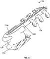
- FIGS. 1A and 1Bshow an example headset 100 for gathering EEG signals via the scalp of a person.
- FIG. 1Aillustrates a perspective view of the front and left side of the person's head
- FIG. 1Billustrates a right side view of the person's head.
- the example headset 100may be used for instance, to gather medical information from a patient in a medical or a home environment, to control aspects of a game or other entertainment device, to provide data as part of a fitness regime, to collect audience measurement data, to control remote devices and/or multiple other uses.
- a band 102e.g., a headband, an elastic band, a strap
- a band 102may be continuous or include multiple adjustably connected portions, and which is to be worn around a head of a person, a user, a subject, a viewer, a participant and/or panelist.
- a participantis a person who has agreed to be monitored. Typically, a participant provides his or her demographic information (e.g., age, race, income, etc.) to a monitoring entity (e.g., The Nielsen Company) that collects and compiles data about a topic of interest (e.g., media exposure).
- a monitoring entitye.g., The Nielsen Company
- the example headset 100includes a plurality of strips, each strip having a plurality of electrodes for receiving signals from the head of the person along the respective strip. More specifically, the headset 100 of the illustrated example includes a first strip 104, a second strip 106, a third strip 108, a fourth strip 110 and a fifth strip 112. Each of the strips 104-112 is intended to be worn over the head of a person from the left side of the head to the right side of the head. Each of the example strips 104-112 is removably attached to the band 102 and each of the strips 104-112 is adjustable on the band 102 to move and position the strips 104-112 in specific locations on the head of a person for reading electrical activity via the scalp. In other examples, the headset 100 may include fewer or more strips (e.g., four or less strips, ten or more strips).
- each of the example strips 104-112includes a respective strap 114-122 and a respective spine structure 124-132.
- the straps 114-122are stretchable and may be made of, for example, elastic.
- each of the strips 104-112includes a plurality (e.g., an array) of individual electrodes 133a-n.
- the electrodes of each strip 104-112are integrated into the respective spine structures 124-132 along with other electrical components such as, for example, a printed circuit board ("PCB").
- PCBprinted circuit board
- the electrodes 133a- nmay have any suitable shape such as, for example, at least a portion of a ring, a ball, a hook and/or an array.
- the electrodes 133a- n , and the strips 104-112 to which the electrodes 133a-n are coupledhave a protective covering such as, for example, a nylon and/or a silver mesh.
- the coveringis a stretchable silver-coated nylon mesh. The covering provides additional shielding and protection.
- the electrodes 133a-n including the coveringmay be machine washable.
- each of the straps 124-132is adjustable (e.g., slidable) along the respective spine structures 124-132 and provides a downward forced on the spine structures 124-132 and, thus, the electrodes (e.g., 133a- n ) coupled thereto.
- each of the spine structures 124-132is comprised of a flexible material such as, for example, plastic, rubber, polyurethane, silicone and/or any other suitable material or combination of materials. The flexibility of the example spine structures 124-132 enables the headset 100 to sit comfortably on the head of a person by adjusting to the shape of the head of the person without applying a discomforting force to the head.
- each of the strips 104-112is removably attached via its ends to the band 102.
- each of the strips 104-112has a first female connector 134-142 on one end (shown in FIG. 1A ) and a second female connector 144-152 on the other end (shown in FIG. 1B ).
- the headset 100also includes a plurality of male connectors 154-172 slidably coupled to the band 102.
- the headset 100includes first male connectors 154-162 that detachably mate with respective ones of the first female connectors 134-142 on one side of the head (shown in FIG.
- each of the male and female connectors 134-172form fasteners (e.g., magnetic fasteners) to removably attach the strips 104-112 to the band 102. More specifically, each of the strips 104-112 is removably coupled to each to the male connectors 154-172 and, thus, also to the band 102.
- the illustrated exampleshows the strips 104-112 adjustably coupled to the band 102 on both the left and right sides of the person's head. In some examples, the strips 104-112 are adjustably coupled to the band 102 on one side and fixedly coupled on the other side.
- the male connectors 154-172are slidably connected to the band 102 and can be moved or repositioned along the band 102.
- the male connectors 154-162are located on the band 102 on one side of the person's head (shown in FIG. 1A ), and the male connectors 164-172 are located on the band 102 on the opposite side of the person's head (shown in FIG. 1B ).
- This arrangement of the male connectors 154-172enables the strips 104-112 to be disposed over the head of the person and attached on each end to the male connectors 154-172, respectively.
- the male connectors 154-172 and the female connectors 134-152are held together by magnetic force (i.e., the male connectors and female connectors form magnetic fasteners).
- the male connectors 154-172 and female connectors 134-152may be coupled together by other fastening mechanisms including, for example, ties, buttons, hooks, snaps, and/or loop and hook fasteners (e.g., Velcro ® fasteners).
- each of the female connectors 134-152is also rotatably coupled to its respective male connector 154-172.
- the male connectors 154-172are slidable along the band 102, and the strips 104-112 are removably (and rotatably) coupled to the male connectors 154-172.
- each of the strips 104-112is removable, rotatable, adjustable and repositionable along the scalp of a person.
- each of the example strips 104-112is adjustable independent of each of the other strips 104-112. The assembly of the male connectors 154-172 and the female connectors 134-152 is described in further detail below.
- the headset 100also includes a support 174 (e.g., a central support) that is coupled to a processing unit 176.
- the central support 174provides sufficient rigidity to the headset 100 to enable the headset 100 to be easily placed and fitted on a person's head.
- each of the strips 104-112is slidably coupled to and supported by the central support 174.
- the central supportcommunicatively couples the electrodes 133a-n to the processing unit 176.
- the central support 174communicatively couples the electrodes of the example strips 104-112 to the processing unit within the processing unit 176 through communication links running through the central support 174.
- each of the strips 104-112is electrically coupled to the central support 174 via, for example, a connection terminal on the respective spines 114-122 and complementary terminal on the central support 174.
- the complementary terminals on the central support 174are independently slidable along the central support 174 to facilitate physical adjustment of the strips 104-112 relative to the head of the person.
- the strips 104-112are wirelessly coupled to the processing unit 176 and/or a remote processor.
- one or more of the strips 104-112may include a transmitter to wirelessly transmit signals (e.g., EEG signals) to the processing unit 176.
- the central support 174supports the strips 104-112 and provides rigidity and structure to the headset 100 but does not function to convey communication signals.
- the headset 100does not include the central support 174 and the processing unit 176, and the signals are communicated to a handheld or other remote receiver.
- the processing unit 176may be contained in a housing and may include other electrical components for processing signals gathered from the electrodes 133a- n .
- the electrical componentsare used to, for example, convert the EEG data from analog data to digital data, amplify the EEG data, remove noise from the data, analyze the data, and transmit the data to a computer or other remote receiver or processing unit.
- the processing unit 176includes hardware and software such as, for example, an amplifier, a signal conditioner, a data processor and/or a transmitter for transmitting signals to a data center or a computer.
- the processing unit 176also includes a connection terminal 178, which may be used, for example, to connect additional electrodes or sensors to the processing unit 176 as discussed in detail below.
- FIG. 2illustrates the example first female connector 134 of the example first strip 104 coupled to the corresponding example first male connector 154.
- the positions of the male connector 154 and the female connector 134may be switched such that the female connector 134 is coupled to the band 102 and the male connector 154 is coupled to the strip 104.
- FIGS. 2-5are a detailed description related to FIGS. 2-5 of the example male connector 154 and the example female connector 134.
- this disclosurealso applies to the example second male connector 164 and the example second female connector 144 on the other side of the first strip 104 and to other strips 106-112 and the corresponding example male connectors 156-162, 166-172 and example female connectors 136-142, 146-152.
- the first strip 104includes the first spine 114 and the first strap 124.
- the first strap 124is disposed within a slot 200 (e.g., a groove, an area between runners or knobs, a slit, etc.) on the first spine 114, and the first strap 124 is slidably adjustable along the first spine 114.
- the first strap 124is elastic and stretchable.
- An end of the first strap 124is slidably coupled to the first female connector 134 (discussed in detail below).
- the first spine 114is engaged to the first female connector 134.
- the end of the first strap 124may extend past the first female connector 134 as discussed in detail below.
- the first female connector 134is removably coupled to the first male connect 154 such that the strip 104 may be selectively removed from the male connector 154 and the band 102 and reattached to the first male connector 154 or another one of the male connectors 156-172.
- the first female connector 134is also rotatable relative to the first male connector 154 to enable adjustment of the relative angle between the first strip 104 and the band 102.
- the first female connector 134 and first male connector 154are magnetically coupled.
- the first female connector 134 and the first male connector 154are attached by other fastening mechanisms.
- FIGS. 3A and 3Bshow top and bottom views of the example first female connector 134.
- the first female connector 134includes a body 300 (e.g., a housing) having a top 302.
- the top 302 of the first female connector 134has a slot 304 (e.g., a channel, a groove, an indentation, etc.), which may, for example, receive the end of the first spine 114 (as shown in FIG. 2 ).
- the slot 304has a hemispherical shape that matches a contour or shape of the end of the first spine 114.
- the slot 304has other contours or shapes that may or may not match the shape of the end of a spine.
- the body 300 of the first female connector 134also has an aperture 306 (e.g., a hole, an opening, etc.) to receive the strap 124 (shown in FIG. 2 ).
- the aperture 306is formed near an end of the slot 304.
- a bottom 308 of the example first female connector 134has a cup or cavity 310 that is formed by an annular rim or protrusion 312 extending outward from the body 300.
- the cavity 310is used to retain a magnetic element or a metallic element as described in detail below.
- the cavity 310is cylindrical and, thus, has a circular cross-section.
- the cup or cavity 310may have a rectangular, square or otherwise shaped cross-section.
- FIGS. 4A and 4Bshow top and bottom views of the example first male connector 154.
- the first male connector 154includes a body 400 (e.g., a housing) forming an elongated ring.
- the body 400has an oval cross-section forming a passage 402 (e.g., an aperture, a hole, an opening, etc.) therethrough.
- the body 400may have a more circular cross-section, a rectangular cross-section or any other suitable shape.
- the passage 402is to receive the band 102 (shown in FIGS. 1A and 1B ).
- a top side 404 of the example first male connector 154has an annular rim or protrusion 406 that extends outward from the top side 404 of the body 400 and which forms a cup or cavity 407.
- a magnet or magnetic plateis disposable in the cavity 407 to facilitate coupling of the example first male connector 154 to the example first female connector 134.
- the protrusion 406is selectively removably insertable into the cavity 310 of the first female connector 134.
- a bottom side 408 of the example first male connector 154has two clips 410, 412. In other examples, there are other numbers of clips such as, for example, one, three, zero, etc.
- the clips 410, 412are elongated sections of the body 400 that are displaced (e.g., indented) into the passage 402 of the body 400.
- the clips 410, 412are spring clips or leaf springs.
- the example first male connector 154includes one or more clips that are not integrally formed with and that are coupled to the first male connector 154 to the join the male connector 154 and the band 102. The example clips 410, 412 frictionally engage the band 102 (shown in FIGS.
- the frictionmay be overcome, for example by human force, to reposition the male connector 154 relative to the band 102.
- other types of clipsmay be used to resist movement of the male connectors 154-172 along the band 102.
- the body 400 of the example first male connector 154forms a ring.
- the body 400may include a slit such that the band 102 may be slid through the slit and into the passage 402 of the body 400 to removably couple the first male connector 154 to the band 102.
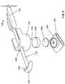
- FIG. 5illustrates an exploded view of the example first female connector 134 and the example first male connector 154 assembly.
- the first strap 124 of the first strip 104passes through the aperture 306 on the first female connector 134.
- the end of the strap 124has a stop 500.
- the stop 500prevents the end of the strap 124 from being pulled through the aperture 306 and, thus, retains the first female connector 134 on the end of the first strip 104.
- the stop 500may be turned sideways such that a longitudinal axis of the stop 500 is aligned with the aperture 306 and is passed through the aperture 306 (i.e., by rotating the stop 50 about 90°).
- the stop 500is curved to match the contour of the first female connector 134 to lie flat against the first female connector 134 when the first strap 124 is pulled tight.
- the stop 500includes an alignment block 502, which matches the profile (e.g., the shape) of the aperture 306. When the stop 500 engages the first female connector 134, the alignment block 502 partially enters the aperture 306 and maintains the position of the stop 500 secure against the first female connector 134.
- the example first female connector 134includes a first disc 504, and the example first male connector 154 includes a second disc 506.
- at least one of the first disc 504 and the second disc 506is a magnet, and the other of the first disc 504 and the second disc 506 is magnetic for interacting with the magnet.
- the magnetic disc 506may be, for example a magnetized metallic plate or other material. In other examples, both of the first disc 504 and the second disc 506 are magnets.
- the first disc 504is to be disposed within the cavity 310 of the first female connector 134, and the second disc 506 is to be disposed within the cavity 407 of the first male connector 154.
- the discs 504, 506may be coupled to their respective connectors 134, 154 by adhesive, friction fit or any other mechanism for coupling two components together.
- the first magnetic disc 504is coupled to the cavity 407 of the first male connector 154
- the second magnetic disc 506is coupled to the cavity 310 of the first female connector 134.
- the female connector 134 or at least a portion of the first female connector 134e.g., the rim 312
- the first male connector 154 or at least a portion of the first male connector 154(e.g., the lip 406) comprises a magnetic material.
- the magnet or the first disc 504 and the magnetic disc or the second disc 506cause the example first female connector 134 and the example first male connector 154 to attract each other and form a magnetic bond.
- the protrusion or lip 406 of the first male connector 154is releasably inserted into the cavity 310 of the first female connector 134 and the attraction (e.g., magnetic force) between the first disc 504 and the second disc 506 holds the example first female connector 134 and the example first male connector 154 together.
- the complementary circular profile of the cavity 310 of the female connector 134 and the circular shape of the protrusion 406 of the male connector 154enable the female connector 134 to be rotated relative to the first male connector 154, which allows the end of the strip 104 to be further adjusted (e.g., angled) on the head of a person relative to the band 102.
- the cavity 310 of the first female connector 134 and the protrusion 406 of the male connector 154may have other shapes including square or rectangular profiles.
- the first male connector 154 and the first female connector 134may fit together as gears with teeth or cogs that engage in a plurality of discrete positions.
- the first female connector 134when adjusting the first strip 104 on the headset 100, the first female connector 134 is coupled to the first male connecter 154 and the stop 500 is engaged with the first female connector 134 (e.g., the position shown in FIG. 2 ).
- the first strip 104is adjusted, for example, tightened, such that a portion of the first strap 124 extends beyond the first female connector 134, and the stop 500 is not positioned against the first female connector 134.
- the aperture 306may include protrusions (e.g., knobs, pins) that engage the side of the first strap 124 to restrict movement (e.g., via friction) of the strap 124 through the aperture 306.
- the first strip 104may be used on different sized heads and may be adjusted accordingly.
- the example first female connector 134is attached to the example first male connector 154 and the first strap 124 may pulled through the aperture 306 until the first strap 104 applies an appropriate pressure against the head of the person. Therefore, the effective length of each one of the example strips 104-112 may be changed.
- different size stripsare manufactured to accommodate different size heads.
- a person with a head measuring 62-64 centimeters (cm)may use a headset with strips measuring a first length
- a person with a head measuring 58-62cmmay use a headset with strips measuring a second length, shorter than the first length. Therefore a plurality of different sized strips may be used with a headset to comfortably accommodate any sized/shape head.
- the example strips 104-112are coupled to the male connectors 154 -172 on the band 102 and then the headset 100 is placed on the head of a person.
- the central support 174 and the processing unit 176may also be attached to the strips 104-112 prior to placing the headset 100 on the head of a person.
- the band 102is placed on the head of a person (e.g., by clipping two ends of the band 102 together or stretching an elastic band over the head) and then each of the example strips 104-112 is individually coupled (e.g., magnetically) to the male connectors 154-172 on the band 102.
- the male connectors 154-172are slidable along the band 102 to adjust the location of the strips 104-112 and, thus, the respective arrays of electrodes on each of the strips 104-112 relative to the head of the person.
- the example female connectors 134-152are also rotatable on their respective example male connectors 154-172, further allowing the strips 104-112 to be positioned (e.g., angled) on the head of a person.
- the magnetic coupling between the male and female connectors 134-172also provides a safety function by enabling example the strips 104-112 to easily be disconnected from the band 102 if too much force is exerted on the band 102. For example, if the strips 104-112 of the headset 100 are snagged or caught on a foreign object, the magnetic force of the male and female connectors may be overcome, and the example strips 104-112 disconnect from the band 102.
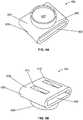
- FIG. 6illustrates an example clip 600 for housing or retaining one or more electrodes such as, for example, a reference or ground electrode.
- the clip 600interfaces with a person's skin by, for example, clipping to the skin of a person (e.g., on an earlobe) or being placed against the skin (e.g., on a forehead).
- an electrodeis used as a reference or ground electrode to provide a reference signal for comparing with the EEG signals gathered from other parts of the person's head by, for example, the headset 100 shown in FIGS. 1A and 1B .
- a reference or ground electrodeis positioned at a point on the person's body that has minimal or no EEG activity or other artifacts and/or noise such as, for example, those indicative of muscle contractions or blood flow.
- the reference or ground electrodeis connected to the earlobe and/or at the tip of a person's nose.
- the clip 600includes a first electrode 602 and a second electrode 604.
- one or both of the electrodes 602, 604is a reference or ground electrode.
- one or both of the electrodesmay be used to gather other EEG signals from a person's head.
- one of the electrodesis used for shielding while the other electrode may be used as a reference or ground electrode or to gather EEG data from the person's head.
- the first electrode 602is coupled to a first terminal 606 via a first wire 608, and the second electrode 604 is coupled to a second terminal 610 via a second wire 612.
- the first and second electrodes 602, 604are similar, and the first and second terminals 606, 610 are similar.
- the description of the features of one of the electrodes 602, 604applies to the other one of the electrodes 602, 604, and the description of the features of one of the terminals 606, 610 applies to the other one of the terminals 606, 610.
- one side of a terminalis shown on the first terminal 606 and the other side of a terminal is shown on the second terminal 610 for illustrative purposes.
- the first and second terminals 606, 610couple the wires 608, 612 and, thus, the electrodes 602, 604 to the example processing unit 176 ( FIGS. 1A and 1B ).
- the first terminal 606has a first connector including three prongs or pins 614a-c protruding from the side of the first terminal 606.
- the first terminal 606has two magnetic connectors or pads 616a, 616b. The pins 614a-c are aligned along a longitudinal axis of the first terminal 606 with the first magnetic pad 616a on one end and the second magnetic pad 616b on the other end.
- the pins 614a-care used to transfer signals/data (e.g., EEG signals) gathered from the electrode 602 to the processing unit 176.
- the processing unit 176includes the receiver 178 (e.g., a terminal), having three apertures 180a-c and two magnetic pads 182a, 182b. Similar to the connectors of the first and second terminals 606, 610, the receiver 178 has matching components such that the three pins 614a-c can be plugged into the three apertures 180a-c to mechanically and electrically couple the terminal 606, 610 to the processing unit 176.
- the magnetic pads 616a, 616b of the terminal 606couple to the magnetic pads 182a, 182b of the processing unit 176 to releasably secure the terminal 606 to the processing unit 176.
- the receiver 178 on the processing unit 176is used for attaching other electrodes or physiological/biological measurement devices (e.g., an EKG sensor, an eye tracking sensor, etc.).
- the additional devicesmay include terminals having similar connectors or terminals (e.g., apertures and pins, connection points) that may be attached to the processing unit 176 or to other terminals attached to the processing unit 176 as discussed below.
- the second terminal 610includes multiple channels or apertures 618a-c and two magnetic pads 620a, 620b.
- the terminals 606, 610may be stacked, such that two or more terminals may be plugged into each other and coupled as a group to the processing unit 176.
- the second terminal 610may be coupled to the processing unit 176 by coupling pins and magnetic pads on the second terminal 610 (similar to the pins 614a-c and the magnetic pads 616a, 616b on the first terminal 606 shown in FIG.
- the apertures 618a-c of the second terminal 610can receive the pins 614a-c from the first terminal 606 to stack the first and second terminals 606, 610 and couple the first terminal 606 to the processing unit 176 via the second terminal 610.
- the magnetic pads 616a, 616b on the first terminal 606align with and, thus, can engage the magnetic pads 620a, 620b as shown on the second terminal 610 and the magnetic force releasably secures the first and second terminal 606, 610.
- a third terminalmay be stacked on the first terminal 606 in a similar manner.
- a fourth terminalalso may be coupled and so forth.
- the terminals 606, 610include a cap or lid 622 to protect the apertures 618a-c and magnetic pads 620a, 620b from the environment.
- FIG. 7shows an exploded view of the example clip 600.
- the clip 600includes a first cavity or cup 700 at a first end and a second cavity or cup 702 at a second end, which are coupled by an intermediary portion or body 704.
- the body 702includes a plurality of slits 706a- n , which retain one or more wires such as, for example, the first wire 608 and/or the second wire 612.
- the slits 706a-nsecure the wires 608, 612 ( FIG.
- the body 704 and the cups 700, 702may be formed as unitary piece (e.g., molded as one component). In other examples, the body 704 and the cups 700, 702 are made of separate pieces and coupled together to form the clip 600. Also, in some examples, the first and second cups 700, 702 include metallic rings or cups molded (e.g., encased) inside the cups 700, 702 (e.g., plastic is poured over the metallic cups). The metallic cups provide shielding against line noise and other type(s) of noise.
- a first disc 708is disposed in the first cup 700 and a second disc 710 is disposed in the second cup 702.
- the one or both of the discs 708, 710are magnetic such as, for example, comprising a metallic material.
- the discs 708, 710are magnetically attracted to the metallic cups molded within the first and second cups 700, 702, such that when the discs 708, 710 are placed in the first and second cups 700, 702, a magnetic force releasably secures the discs 708, 710 in the respective cup 700, 702.
- the clip 600includes the first electrode 602 disposed in the first cup 700 and the second electrode 604 disposed in the second cup 702.
- the first electrode 602includes a first flange 712 to hold such as, for example, via a friction fit, the first electrode 602 in the first cup 700.
- the first flange 712engages an undercut or a wall of the first cup 700.
- the second electrode 604includes a second flange 714 to hold the second electrode 604 in the second cup 702.
- an edge of the electrodes 602, 604provide the friction to secure the electrodes 602, 604 in place.
- the electrodes 602, 604do not include flanges and are, for example, flat or cup-shaped on the bottom.
- the first and second electrodes 602, 604are made of a metallic material and/or are coated (e.g., anodized or plated) with a metallic material (e.g., silver, gold, etc.).
- the metallic electrodes and/or the coatingsare magnetically attracted to the discs 708, 710, and the magnetic force releasably holds the electrodes 602, 604 in the respective cups 700, 702.
- the clip 600has two electrodes 602, 604.
- the cups 700, 702include both discs 708, 710 to create a magnetic force and hold the clip against the body (e.g., skin, an ear lobe, etc.) of a person.
- the example clip 600may be coupled against a person's forehead or to a person's earlobe or nose.
- the clip 600is in the flat or substantially flat orientation shown in FIGS. 6 and 7 , with the first and second cups 700, 702 facing the same direction.
- the clip 600may be coupled to the band 102 ( FIGS. 1A and 1B ) to hold the clip 600 on the forehead.
- the body 704 of the clip 600may be folded or bent such the first cup 700 and the second cup 702 are moved toward each other in an opposed orientation.
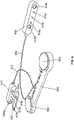
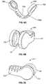
- FIGS. 8A, 8B, and 8Cillustrate different views of the clip 600 in bent and partially bent configurations.
- the body 704may be made of, for example, a plastic, a rubber, a thermoplastic elastomer, silicone and/or any other material capable of being bent multiple times without fracturing.
- the body 704is pliable such that the clip 600 is configurable between the flat position of FIG. 6 and the bent position of FIGS. 8B and 8C such that the clip 600 may be used on the forehead, then on the earlobe, then back on the forehead as desired.
- the discs 708, 710e.g., magnetic plates, metal plates
- the cups 700, 702cause the cups 700, 702 to magnetically attract each other and, thus, the clip 600 remains in a closed position or bent position (e.g., the position shown in FIGS. 8B and 8C ).
- the magnetic forceis sufficient to extend through human tissue to hold the clip 600 to the earlobe.
- the clip 600may include only the second disc 710 coupled to the second cup 702. When bent towards each other, the metallic coating on the first electrode 602 is magnetically attracted to the second disc 710, which holds the clip 600 on the earlobe.
- the first cup 700may be metallic or otherwise magnetic, and the first cup 700 is magnetically attracted to the second disc 710, which holds the clip 600 on the earlobe regardless of the composition of the electrode 602.
- FIG. 9is a block diagram of an example processing system 900 for use with the example headset 100.
- the example system 900includes a plurality of electrodes 902 such as, for example, the electrodes 133a-n of the example headset 100.
- the electrodes 902are coupled, for example, to a headset to be worn on a head of a subject.
- the headset 100includes the band 102 to be worn on a head of a person and the plurality of removable and adjustable strips 104-112 that extend over the head of the person when attached to the band 102.
- each of the strips 104-112includes their respective strap 114-122 and respective spine structure 124-132 having a plurality of electrodes (e.g., the electrodes 133a- n ).
- each end of each one of the strips 104-112is removably and rotatably fastened (e.g., magnetically) to the band 102 such that the electrodes can be moved to different positions on the head and/or removed from the band 102.
- the headset 100includes numerous channels of electrodes such that multiple (e.g., 2000 or more) electrodes are included in the example system 900.
- the pressure applied on the head by each electrodemay be adjusted by adjusting the strap associated with each of the strips 104-112. In other examples, different size strips may be added and/or removed that fit comfortably over the head of the person.
- one or more electrodes 902are coupled to a body of a person via a clip such, as for examples, the clip 600 shown in FIG. 6 .
- the clipretains one or two electrodes and the clip is laid flat against the skin (e.g., the forehead) of the person to engage the electrodes to the skin.
- the clipis attached to the band of the headset.
- the clip 600includes the body or intermediary portion 704 that is flexible and foldable.
- the clip 600includes one or two plates or discs (e.g., the discs 708, 710) that are attracted (e.g., magnetically) to each other such that a bent or folded clip 600 is releasably held onto the skin of a person such as, for example, the earlobe or the nose of a person.
- the electrodes 902, which may be, for example, the electrodes 602, 604,are used to provide a ground or reference signal. In some examples, the electrodes are used as a shield.
- the example electrodes 902may also be adjustably mechanically coupled, such as for example, via the strips to the band where the magnetic fasteners are supported to releasably hold the strips and, thus, the electrodes 902 in different positions along the scalp.
- An example magnetic fastenerincludes the male connector and female connector assembly disclosed above.
- the electrodes 902are also communicatively coupled to a processing unit 904 (e.g., the processing unit 176 of the headset 100 shown in FIGS. 1A and 1B ) via a communication link 906, which may be for example a wired or wireless communication link including, for example, the PCB communication channels disclosed above.
- the communication link 906may be, for example, incorporated in the central support 174 of the headset 100.
- the strips (and their respective electrodes)are slidably coupled along the central support.
- the central supportincludes communication links (e.g., wires) to communicatively coupled each of the strips to the housing.
- the example processing unit 904includes an analog-to-digital converter 908, a signal conditioner 910, a database 912, an analyzer 914 and a transmitter 916.
- the analog-to-digital converter 908converts the analog signals received at the electrodes 902 to digital signals.
- the analog-to-digital converter 908is located in the processing unit 904 in the housing of the headset.
- the analog-to-digital converter 908comprises multiple A-D converters located to service individual or sets of the electrodes to convert the signals as close to the source as possible, which may further reduce interference.
- the signal conditioner 910 of the illustrated exampleprepares the gathered signals so that the data is in a more usable form.
- the signal conditioner 910may include an amplifier to amplify the signal to a more detectable level.
- the signal conditioner 910may include a filter to remove noise from the signal.
- the filtermay also be used as a bandpass filter to pass one or more frequency bands and/or manipulate select bands depending on the desired processing and/or analysis.
- each of the electrodes 902may include a signal conditioner at or near the electrode 902.
- the example signal conditioner 910may include hardware and/or software to execute a signal conditioning method.
- the signal conditionerincludes a detrending unit to compensate for electrode polarization, in which there is slow movement of the voltage signal unrelated to brain wave activity due to polarization of the electrodes.
- the example processing unit 904also provides signal processing that may include hardware and/or software to execute Fast Fourier Transform (FFT) calculations, coherence measurements and/or custom adaptive filtering.
- FFTFast Fourier Transform
- the analyzer 914is to analyze the data gathered from the electrodes 902 and processed by the analog-to-digital converter 908 and the signal conditioner 910 in accordance with one or more analysis protocols depending on the desired study. For example, in accordance with some studies, the analyzer 914 may process the data to determine one or more of a subject's mental state, physiological state, attention, resonance or memory, emotional engagement and/or other suitable characteristics of the subject.
- the transmitter 916communicates the data at any stage of processing and/or the results of the analysis from the analyzer 914 to an output 918.
- the output 918could be a handheld device, an alarm, a display screen on the headset, a remote server, a remote computer and/or any other suitable output.
- Data transmissionmay be implemented by Bluetooth transmission, wi-fi transmission, ZiGBee transmission and/or encryption before transmission.
- the database 912stores all data gathered streams. The streams can be buffered for streaming or stored on-board (i.e., at the headset) for periodic or aperiodic uploads during, for example, low-activity periods.
- the processing unit 904 components 908-916are communicatively coupled to other components of the example system 900 via communication links 920.
- the communication links 920may be any type of wired connection (e.g., a databus, a USB connection, etc.) or a wireless communication mechanism (e.g., radio frequency, infrared, etc.) using any past, present or future communication protocol (e.g., Bluetooth, USB 2.0, USB 3.0, etc.).
- the components of the example system 900may be integrated in one device or distributed over two or more devices.
- the example processing unit 904the example signal conditioner 910, the example A/D converter 908, the example database 912, the example transmitter 916, the example analyzer 914, the example output 918 and/or, more generally, the example system 900 of FIG. 9 may be implemented by hardware, software, firmware and/or any combination of hardware, software and/or firmware.
- any of the example processing unit 904, the example signal conditioner 910, the example A/D converter 908, the example database 912, the example transmitter 916, the example analyzer 914, the example output 918 and/or, more generally, the example system 900 of FIG. 9could be implemented by one or more analog or digital circuit(s), logic circuits, programmable processor(s), application specific integrated circuit(s) (ASIC(s)), programmable logic device(s) (PLD(s)) and/or field programmable logic device(s) (FPLD(s)).
- ASICapplication specific integrated circuit
- PLDprogrammable logic device
- FPLDfield programmable logic device
- At least one of the example processing unit 904, the example signal conditioner 910, the example A/D converter 908, the example database 912, the example transmitter 916, the example analyzer 914 or the example output 918is/are hereby expressly defined to include a tangible computer readable storage device or storage disk such as a memory, a digital versatile disk (DVD), a compact disk (CD), a Blu-ray disk, etc. storing the software and/or firmware.
- the example system 900 of FIG. 9may include one or more elements, processes and/or devices in addition to, or instead of, those illustrated in FIG. 9 , and/or may include more than one of any or all of the illustrated elements, processes and devices.
- FIGS. 10 and 11Flowcharts representative of example instructions, at least some of which are machine readable, for implementing the headset 100 and/or system 900 of FIGS. 1A-9 are shown in FIGS. 10 and 11 .
- the machine readable instructionscomprise a program for execution by a processor such as the processor 1212 shown in the example processing platform 1200 discussed below in connection with FIG. 12 .
- the programmay be embodied in software stored on a tangible computer readable medium such as a CD-ROM, a floppy disk, a hard drive, a digital versatile disk (DVD), or a memory associated with the processor 1212, but the entire program and/or parts thereof could alternatively be executed by a device other than the processor 1212 and/or embodied in firmware or dedicated hardware.
- example programis described with reference to the flowcharts illustrated in FIGS. 10 and 11 , many other methods of implementing the example headset 100 and/or example system 900 may alternatively be used. For example, the order of execution of the blocks may be changed, and/or some of the blocks described may be changed, eliminated, or combined.
- the example process of FIG. 11 and at least a portion of the example process of FIG. 10may be implemented using coded instructions (e.g., computer and/or machine readable instructions) stored on a tangible computer readable storage medium such as a hard disk drive, a flash memory, a read-only memory (ROM), a compact disk (CD), a digital versatile disk (DVD), a cache, a random-access memory (RAM) and/or any other storage device or storage disk in which information is stored for any duration (e.g., for extended time periods, permanently, for brief instances, for temporarily buffering, and/or for caching of the information).
- coded instructionse.g., computer and/or machine readable instructions
- a tangible computer readable storage mediumsuch as a hard disk drive, a flash memory, a read-only memory (ROM), a compact disk (CD), a digital versatile disk (DVD), a cache, a random-access memory (RAM) and/or any other storage device or storage disk in which information is stored for any duration (e
- tangible computer readable storage mediumis expressly defined to include any type of computer readable storage device and/or storage disk and to exclude propagating signals.
- tangible computer readable storage mediumand “tangible machine readable storage medium” are used interchangeably. Additionally or alternatively, the example process of FIG. 11 and at least a portion of the example process of FIG.
- non-transitory computer and/or machine readable mediumsuch as a hard disk drive, a flash memory, a read-only memory, a compact disk, a digital versatile disk, a cache, a random-access memory and/or any other storage device or storage disk in which information is stored for any duration (e.g., for extended time periods, permanently, for brief instances, for temporarily buffering, and/or for caching of the information).
- a non-transitory computer readable mediumis expressly defined to include any type of computer readable device or disk and to exclude propagating signals.
- FIG. 10is a flowchart illustrating an example process of gathering EEG data (block 1000) that may be implemented, for example, with the headset 100 disclosed herein.
- the example processbeings by placing a band on a head of a person (block 1002) such as, for example, the band 102 shown in FIGS. 1A and 1B .
- the example bandas disclosed above, is elastic and may be stretched over the head of the person.
- the bandincludes a connection point such as, for example, a clip that joins two ends of the band.
- the example process 1000includes attaching and adjusting one or more strips (block 1004).
- each stripincludes a plurality of electrodes and each strip is removably and adjustably coupled on each end to the band such that the strip is disposed over the head of the person.
- the example headset 100 disclosed aboveincludes the plurality of attachable/detachable strips 104-112 each having their respective spine structures 124-132 and straps 114-122.
- the spine structures 124-132include an array (e.g., one or more) of electrodes for gathering signals along the scalp of the person.
- the headset 100may include two, three, four or ten or more individual strips 104-112.
- the strips 104-12are fastened (e.g., magnetically) at each end to the band 102 and are disposed over the head of a person.
- the strips 104-112include the female connectors 134-152 that magnetically couple to the male connectors 154-172, which in turn slidably couple to the band 102.
- each of the male connectors 154-172includes a passage that allows the male connectors 154-172 to slide along the band 102 and, thus, the ends of the strips 104-112 are also slidable along the band 102 when connected to the male connectors 154-172, which laterally adjusts the respective strips 104-112.
- the female connectors 134-152are also rotatable on the male connectors 154-172 to adjust an angle of the respective strips 104-112 relative to the band 102. Therefore, the strips 104-112 may be independently adjusted on the head of a person laterally and/or rotationally to a specific location where EEG readings are desired and/or are most effective.
- the headset 100includes the central support 174, and adjusting the strip 104-112 includes independently sliding the strip 104-112 along the central support 174.
- only one stripis attached to the band and adjusted. If additional strip(s) are desired, then more strip(s) may be added as needed and/or desired (block 1004).
- additional strip(s)are desired, then more strip(s) may be added as needed and/or desired (block 1004).
- the headsetis pre-assembled and the example process 1000 includes placing the headset on the head of the person and adjusting the strips such as, for example, laterally and/or rotationally adjusting the strips. With a pre-assembled headset, attachment of the strips may occur before the example EEG data gathering process 1000. For example, a manufacturer may attach the strips.
- the example process 1000includes determining whether a reference or ground electrode separate from the headset is to be used (block 1006). If a reference or ground electrode separate from the headset is not to be used, then signals are gathered (block 1008) from the one or more of the strip(s) that are coupled to the headset.
- the example process 1000includes placing one or more electrodes in a clip (block 1010) such as, for example, the example clip 600 disclosed above.
- a first electrodeis placed in one of the cups 700, 702 and a second electrode may be placed in the other cup 700, 702.
- the example process 1000includes attaching the clip to the band (block 1012) or clipping the clip to a body of the person (block 1014).
- the clip 600includes the flexible body 704 that may be laid flat or bent. In the flat position, the clip 600 (and the one or two electrodes) may be attached to the band 102.
- the clip 600is attached at a front of the band 102 such that the electrodes (e.g., the electrodes 602, 604) lie against the forehead of the person.
- the clip 600may be used to clip onto the skin or a portion of the person's body.
- the discs 708, 710 in the cups 700, 702may be magnets and/or metallic plates are arranged to attract each other.
- the body 704 of the clip 600is flexible and as the ends of the clip 600 attract each other (e.g., via magnetic force), the clip 600 may be clipped on the skin or body of a person such that the electrodes 602, 604 are in contact with the skin.
- the clip 600is clipped onto an earlobe of the person.
- two electrodes 602, 604are used in the clip 600 and, therefore, two reference or ground signals are gathered from the clip 600.
- the electrodes 602, 604are not reference or ground electrodes, but are utilized to gather additional EEG signals from additional regions on the person's body (e.g., the forehead).
- one of the electrodes 602, 604is used as a shield for the other electrode in the clip 600.
- the example process 1000also includes determining if additional ground or reference electrodes are to be used (block 1016). If it is determined that additional ground or reference electrodes are required, then additional clips can be used to attach the ground or reference electrodes to the body of the person (e.g., attached to the band, attached to the earlobe) (block 1018).
- the example process 1000also includes attaching terminals, to which the electrodes are coupled to a processing unit or to another terminal (block 1020).
- the ground or reference electrodes 602, 604are coupled to terminals 606, 610, which are used to couple the electrodes 602, 604 to the processing unit 176 on the headset 100.
- the example terminals 606, 610 disclosed aboveinclude fasteners such as, for example, the pins 614a-c, the magnetic pads 616a, 616b, 620a, 620b, and apertures 618a-c to enable the attachment disclosed above.
- the terminalsare pre-attached to the processing unit and/or another terminal.
- the example process 1000includes gathering signals from the electrodes of the headset and/or the one or more ground/reference electrodes (block 1008).
- the signalsmay be monitored, analyzed, manipulated, etc. Once the monitoring is complete, the example method 1000 ends (block 1022).
- FIG. 11is a flowchart illustrating an example process of analyzing EEG data (block 1100) collected from the example headset 100 and implemented by the example system 900 of FIG. 9 .
- the example headset 100has a plurality of electrodes that contact the scalp of a subject to receive electrical signals from the subject's brain.
- the example process of analyzing EEG data (1100)includes reading the EEG signals from the electrodes (block 1102).
- the signalsare converted from an analog signal to a digital signal (block 1104).
- the analog-to-digital conversiontakes place in a processing unit, such as, for example, the processing unit 904 of the example system 900.
- the analog-to-digital conversiontakes place adjacent the electrodes within the headset to convert the signal as close to the source as possible.
- the signalsare conditioned (block 1106) to improve the usefulness of the signals and the accessibility of the data contained therein.
- the conditioningmay include amplifying the signals and/or filtering the signals (e.g., with a bandpass filter).
- the signalsare analyzed (block 1108) to, for example, determine a mental state of the subject, a health condition, an engagement with media as an audience member or effectiveness of the media, an input desire for an electrical device and/or otherwise in accordance with the teachings of this disclosure.
- the EEG datais analyzed to evaluate brain activity in particular frequency bands of the EEG data and/or in particular regions of the brain. Assessments and/or calculations of the relationship(s) and correlation(s) of the frequency bands and regions of activity of the EEG data are used to determine an emotional or mental state of a person including, for example, attention, emotional engagement, memory or resonance, etc.
- the regions of brain activity, the interaction between regions of brain activity, and/or the interactions including couplings between frequency bandssignify particular mental states.
- inter-regional coherencies of frequency band as measured from gain and/or phasemay be used to estimate the effectiveness of media in evoking a desired response (e.g., attention) in a person.
- inter-hemispheric measurement, asymmetry in one or more frequency bands, asymmetry in inter-regional intra-hemispheric coherence and/or asymmetry in inter-regional intra-hemispheric inter-frequency couplingmay be used to measure of emotional engagement.
- the signalsmay be analyzed to determine or calculate an interaction between a first frequency band of the EEG data and a second frequency band of the EEG by detecting a first pattern of oscillation in the first frequency band, detecting a second pattern of oscillation in the second frequency band and identifying a degree of phase synchrony between the first pattern and the second pattern.
- the analysismay, for example, provide an effectiveness evaluation of media the person observed or consumed when the signals were generated. In this example, the media effectiveness may be based on the degree of phase synchrony.
- the signalsmay be analyzed to detect a first pattern of oscillation in a first frequency band of EEG data and to detect a second pattern of oscillation in a second frequency band of the EEG data.
- a degree of phase synchronyis identified between the first pattern from the first frequency band and the second pattern from the second frequency band by detecting a repeating sequence of relative phase angles between the first pattern of oscillation in the first frequency band and the second pattern of oscillation in the second frequency band.
- the analysisalso may, for example, provide an effectiveness evaluation of media the person observed or consumed when the signals were generated. In this example, the media effectiveness evaluation is based on the degree of the phase synchrony at a specific point in time.
- the signalsmay be analyzed to determine effectiveness data for media based on a degree of asymmetry between a first frequency band of the EEG data for measured in a first hemisphere of a brain of a panelist and a second frequency band of the EEG data measured in a second hemisphere of the brain.
- the degree of asymmetryis identified by detecting a first amplitude of the first frequency band and detecting a second amplitude of the second frequency band.
- the analysiscompares the first amplitude and the second amplitude to determine a difference between the first amplitude of the first frequency band and the second amplitude of the second frequency band.
- the degree of asymmetryis assigned to the relationship between the first frequency band and the second frequency band based on the difference between the first amplitude of the first frequency band and the second amplitude of the second frequency band.
- the effectiveness of the mediais based on a degree of inter-frequency, inter-hemispheric asymmetry, which is identified by comparing the amplitudes of two frequency bands from different hemispheres.
- the an interaction between a first frequency band of EEG data and a second frequency band of EEG data of the signalsis analyzed by calculating a degree of phase synchrony or amplitude synchrony.
- the phase synchrony or amplitude synchronyis determined by detecting a first pattern of oscillation in the first frequency band and detecting a second pattern of oscillation in the second frequency band.
- a repeating sequence of phase angles or relative amplitude between the first pattern of oscillation in the first frequency band and the second pattern of oscillation in the second frequency bandis detected. The effectiveness of the media is based on the interaction.
- the signalsare analyzed to determine effectiveness of media based on a first asymmetry between two amplitudes from two frequency bands and a second asymmetry between two different amplitudes of the frequency bands.
- the analysisidentifies a first asymmetry in two frequency bands of EEG data related to a first portion of the media. The first asymmetry identified by comparing a first amplitude of the first frequency band and a second amplitude of the second frequency band to determine a first difference between the first amplitude of the first frequency band and the second amplitude of the second frequency band.
- a first valueis assigned to the first asymmetry based on the first difference between the first amplitude of the first frequency band and the second amplitude of the second frequency band.
- the analysisalso includes identifying a second asymmetry in two frequency bands of EEG data related to a second portion of the media.
- the first and second portions of the mediamay be temporally disparate portions of the media or different portions that are concurrently experienced by the panelist (e.g., video and audio).
- the second asymmetryis identified by comparing a third amplitude of the first frequency band and a fourth amplitude of the second frequency band to determine a second difference between the third amplitude of the first frequency band and the fourth amplitude of the second frequency band.
- a second valueis assigned to the second asymmetry based on the second difference between the third amplitude of the first frequency band and the fourth amplitude of the second frequency band.
- An effectiveness of the mediais assessed for each of the first and second portions based on the first value of the first asymmetry and the second value of the second asymmetry.
- the signalsare transmitted to an output (block 1110), such as, for example, the output 918 of the example system 900.
- Example modes of outputare detailed above including, for example, sounding an alarm, displaying a message and/or other alert on a screen, issuing a report to a local and/or remote computer and/or any other suitable output.
- the outputmay include the wired or wireless communications detailed herein.
- the outputincludes data reflected of a person paying attention, the person not paying attention, the person in a state of semi-involvement with a media program, or other mental state of the person, and the identity of the program are transmitted to, for example a remote data facility.
- Raw data, processed data, a history log or an indicator of audience measurementalso may be transmitted to the remote data for collection.
- the remote data facilitymay be, for example, a marketing company, a broadcast company, an entertainment studio, a television network and/or any other organization that might benefit from or otherwise desire to know when people are and/or are not focused on broadcast programs and what those programs are. This example allows broadcasting companies and/or marketing personnel to analyze which programs people are watching, when they are watching the programs and/or when they are focused during the broadcast.
- the example process 1100ends (block 1112).
- FIG. 12is a block diagram of an example processing platform 1200 capable of executing the one or more of the instructions of FIGS. 10 and 11 to implement one or more portions of the apparatus and/or systems of FIGS. 1A-9 .
- the processing platform 1200can be, for example, a processor in a headset, a server, a personal computer, a mobile device (e.g., a cell phone, a smart phone, a tablet such as an iPad TM ), a personal digital assistant (PDA), an Internet appliance and/or any other type of computing device.
- a mobile devicee.g., a cell phone, a smart phone, a tablet such as an iPad TM
- PDApersonal digital assistant
- the processor platform 1200 of the illustrated exampleincludes a processor 1212.
- the processor 1212 of the illustrated exampleis hardware.
- the processor 1212can be implemented by one or more integrated circuits, logic circuits, microprocessors or controllers from any desired family or manufacturer.
- the processor 1212 of the illustrated exampleincludes a local memory 1213 (e.g., a cache).
- the processor 1212 of the illustrated exampleis in communication with a main memory including a volatile memory 1214 and a non-volatile memory 1216 via a bus 1218.
- the volatile memory 1214may be implemented by Synchronous Dynamic Random Access Memory (SDRAM), Dynamic Random Access Memory (DRAM), RAMBUS Dynamic Random Access Memory (RDRAM) and/or any other type of random access memory device.
- the non-volatile memory 1216may be implemented by flash memory and/or any other desired type of memory device. Access to the main memory 1214, 1216 is controlled by a memory controller.
- the processor platform 1200 of the illustrated examplealso includes an interface circuit 1220.
- the interface circuit 1220may be implemented by any type of interface standard, such as an Ethernet interface, a universal serial bus (USB), and/or a PCI express interface.
- one or more input devices 1222are connected to the interface circuit 1220.
- the input device(s) 1222permit(s) a person to enter data and commands into the processor 1212.
- the input device(s)can be implemented by, for example, an audio sensor, a microphone, a camera (still or video), a keyboard, a button, a mouse, a touchscreen, a track-pad, a trackball, isopoint and/or a voice recognition system.
- One or more output devices 1224are also connected to the interface circuit 1220 of the illustrated example.
- the output devices 1224can be implemented, for example, by display devices (e.g., a light emitting diode (LED), an organic light emitting diode (OLED), a liquid crystal display, a cathode ray tube display (CRT), a touchscreen, a tactile output device and or a light emitting diode (LED).
- the interface circuit 1220 of the illustrated examplethus, typically includes a graphics driver card, a graphics driver chip or a graphics driver processor.
- the interface circuit 1220 of the illustrated examplealso includes a communication device such as a transmitter, a receiver, a transceiver, a modem and/or network interface card to facilitate exchange of data with external machines (e.g., computing devices of any kind) via a network 1226 (e.g., an Ethernet connection, a digital subscriber line (DSL), a telephone line, coaxial cable, a cellular telephone system, etc.).
- a communication devicesuch as a transmitter, a receiver, a transceiver, a modem and/or network interface card to facilitate exchange of data with external machines (e.g., computing devices of any kind) via a network 1226 (e.g., an Ethernet connection, a digital subscriber line (DSL), a telephone line, coaxial cable, a cellular telephone system, etc.).
- DSLdigital subscriber line
- the processor platform 1200 of the illustrated examplealso includes one or more mass storage devices 1228 for storing software and/or data.
- mass storage devices 1228include floppy disk drives, hard drive disks, compact disk drives, Blu-ray disk drives, RAID systems, and digital versatile disk (DVD) drives.
- the coded instructions 1232 of FIGS. 10 and 11may be stored in the mass storage device 1228, in the volatile memory 1214, in the non-volatile memory 1216, and/or on a removable tangible computer readable storage medium such as a CD or DVD.
Landscapes
- Health & Medical Sciences (AREA)
- Life Sciences & Earth Sciences (AREA)
- Engineering & Computer Science (AREA)
- General Health & Medical Sciences (AREA)
- Veterinary Medicine (AREA)
- Biophysics (AREA)
- Biomedical Technology (AREA)
- Heart & Thoracic Surgery (AREA)
- Medical Informatics (AREA)
- Molecular Biology (AREA)
- Surgery (AREA)
- Animal Behavior & Ethology (AREA)
- Physics & Mathematics (AREA)
- Public Health (AREA)
- Pathology (AREA)
- Psychiatry (AREA)
- Psychology (AREA)
- Textile Engineering (AREA)
- Measurement And Recording Of Electrical Phenomena And Electrical Characteristics Of The Living Body (AREA)
- Otolaryngology (AREA)
- Measuring And Recording Apparatus For Diagnosis (AREA)
- Sampling And Sample Adjustment (AREA)
- Investigating Or Analyzing Materials By The Use Of Magnetic Means (AREA)
- Magnetic Treatment Devices (AREA)
- Analysing Materials By The Use Of Radiation (AREA)
Description
- This disclosure relates generally to neurological and physiological monitoring, and, more particularly, to methods and apparatus to gather and analyze electroencephalographic data.
- Electroencephalography (EEG) involves measuring and recording electrical activity resulting from thousands of simultaneous neural processes associated with different portions of the brain. EEG data is typically measured using a plurality of electrodes placed on the scalp of a person to measure voltage fluctuations resulting from this electrical activity within the neurons of the brain. Subcranial EEG can measure electrical activity with high accuracy. Although bone and dermal layers of a human head tend to weaken transmission of a wide range of frequencies, surface EEG also provides useful electrophysiological information.
US 2009/0171181 A1 discloses a hat-shaped apparatus main body that has a plurality of holder pieces and a belt that connects the holder pieces on which electrodes are mounted. The electrodes pass through through-holes and is fixed by a nut to hold a front holder piece and the belt.US 2011/0319975 A1 shows a head gear with a plastic head band and fabric C shaped cross band. A circular knob is provided to increase or decrease the length of the head band. The head band has protrusions to hold the cross bands in position. A disc shaped section has holes to accommodate electrode adapters.US 2005/0197556 A1 discloses a neurofeedback device that includes a headband, at least one cross strap, and a chin strap. The cross-strap is configured to hold at least one electrode holder securely against the head of a patient. Each end of the cross strap may comprise a segment of one side of a hook and loop fastener that may be configured to attach to a segment of the headband.FIG. 1A illustrates a perspective view of an example headset with example removable strips for gathering EEG signals in accordance with the teaching of this disclosure.FIG. 1B illustrates a side view of the example headset with the example removable strips shown inFIG. 1 A .FIG. 2 is an enlarged view of an example fastener of an example one of the strips of the example headset ofFIGS. 1A and1B .FIG. 3A is a perspective top view of an example female connector of the example fastener ofFIG. 2 .FIG. 3B is a perspective bottom view of the example female connector shown inFIG. 3A .FIG. 4A is a perspective top view of an example male connector of the example fastener ofFIG. 2 .FIG. 4B is a perspective bottom view of the example male connector shown inFIG. 4A .FIG. 5 is an exploded view of the example fastener ofFIG. 2 .FIG. 6 illustrates a perspective view of an example electrode clip in accordance with the teachings of this disclosure.FIG. 7 illustrates an exploded view of the example electrode clip shown inFIG. 6 .FIG. 8A is a perspective view of the example electrode clip ofFIG. 6 partially bent around a midpoint.FIG. 8B is a perspective top view of the example electrode clip ofFIG. 6 bent around a midpoint.FIG. 8C is a perspective side view of the example clip ofFIG. 6 bent around a midpoint.FIG. 9 is a block diagram of an example circuit from the headset inFIG. 1 .FIG. 10 is a flowchart representing example instructions, at least some of which are machine readable, for implementing an example headset with removable and adjustable strips and gathering EEG data in accordance with the teachings of this disclosure.FIG. 11 is a flowchart representative of example machine readable instructions for analyzing EEG data gathered from an example headset with removable and adjustable strips in accordance with the teachings of this disclosure.FIG. 12 illustrates an example processor platform that may execute one or more of the instructions ofFIGS. 11 and12 to implement any or all of the example methods, systems and/or apparatus disclosed herein.- Certain examples are shown in the above-identified figures and disclosed in detail below. In describing these examples, like or identical reference numbers are used to identify the same or similar elements. The figures are not necessarily to scale and certain features and certain views of the figures may be shown exaggerated in scale or in schematic for clarity and/or conciseness. Additionally, several examples have been described throughout this specification.
- Biological cells and tissues have electrical properties that can be measured to provide information regarding the functioning of the cell or tissue. Various types of electrophysiological techniques have been developed to measure electrical signals from a body. For example, electrocardiography (ECG or EKG) measures electrical activity in a heart. Electroencephalography (EEG) measures electrical activity in a brain. Electrocorticography (ECoG) measures electrical activity using electrodes placed directly on an exposed surface of a brain to record electrical activity in a cerebral cortex. Electromyography (EMG) measures electrical activity in a muscle. Electrooculography (EOG) measures the resting potential of a retina, and electroretinography measures electrical responses of retinal cells. These and/or other electrophysiological signals are important in the treatment, diagnosis and monitoring of many health conditions.
- EEG data is indicative of electrical activity of neurons including neural depolarization in the brain due to stimuli of one or more of the five senses (evoked activity) as well as from thought processes (spontaneous activity) that generate electrical activity in the brain. Summations of these electrical activities, (e.g., brainwaves), propagate to the surface (e.g., the scalp) and are detectable with electroencephalograms. Current flow in the human body is due to ion flow. Thus, a biopotential electrode is used to form an electrical double layer with the human skin to sense the ion distribution.
- EEG data can be classified in various bands. Brainwave frequencies include delta, theta, alpha, beta and gamma frequency ranges. Delta waves are classified as those less than about 4 Hertz (Hz) and are prominent during sleep. Theta waves have frequencies between about 3.5Hz to about 7.5Hz and are associated with memories, attention, emotions, and sensations. Theta waves are typically prominent during states of internal focus. Alpha frequencies reside between about 7.5Hz and about 13Hz. Alpha waves are prominent during states of relaxation. Beta waves have a frequency range between about 14Hz and about 30Hz. Beta waves are prominent during states of motor control, long range synchronization between areas, analytical problem solving, judgment, and decision making. Gamma waves occur between about 30Hz and about 100Hz and are involved in binding of different populations of neurons together into a network for the purpose of carrying out a certain cognitive or motor function, as well as in attention and memory. Skull and dermal layers tend to attenuate waves above about 75Hz and, as a result, high gamma band or kappa band waves are less easily measured than waves in lower frequency bands. EEG data may be used to determine an emotional or mental state of a person including, for example, attention, emotional engagement, memory or resonance, etc.
- EEG signals may be measured using a plurality of electrodes placed on a scalp of a person (e.g., a user, a viewer, a subject, a panelist, a participant or a patient) to measure voltage fluctuations lasting milliseconds and resulting from electrical activity associated with post synaptic currents occurring within neurons of a brain. Though subcranial EEG can measure electrical activity with high accuracy, surface electrodes such as, for example, dry electrodes also provide useful neuro-response information.
- To enable the surface EEG electrodes to effectively receive signals from the brain, the electrodes are placed as close to the scalp as possible. The electrodes may be manually placed upon a subject's head or may be contained in a wearable apparatus such as, for example, a headset. Many known EEG headsets utilize a bulky helmet or complicated head-strap type assembly. To decrease impedance, these headsets are typically strapped tightly onto a user's head to decrease the distance between the electrodes and the tissue of the scalp. However, too much pressure such as, for example, greater than two Newtons per millimeter square (N/mm2) results in discomfort for the subject. Further, these known headsets have limited adjustability and are often uncomfortable to wear because they do not account for differently sized heads and/or shapes of heads.
- The invention concerns an apparatus as defined in independent claim 1 and a corresponding method as defined in independent claim 13. Preferred embodiments are defined in the dependent claims. Example headset devices and accompanying components for receiving neuro-response data from a person's brain are disclosed herein. An example headset disclosed herein is portable and comprises a plurality of independently adjustable strips attached to a headband. In some examples, the strips are removable. The examples headset devices into which electrodes are incorporated are adjustable to enhance comfort and noise reduction, as disclosed in greater detail below, Some such example headsets provide a simple, cost effective and reliable solution for the use of a large number of dry electrodes. Some such example headsets ensure comfort, good electrode contact, through the hair operation, and shielding against line noise and other type(s) of noise. Examples disclosed herein also include independently removable and adjustable components to enhance comfort, wearability and safety.
- Example clips are also disclosed herein that retain electrodes such as, for example, ground or reference electrodes. In some examples, the clips are used to attach one or more electrodes directly to the body of a person, and the clips are self-fastening such as, for example, with magnetic fasteners, so that additional hardware is not needed to secure the electrodes to the body such as, for example, to an earlobe of the person. Example clips also include terminals to releasably couple the clips and, thus, the electrodes, to a processing unit coupled to the headset. The terminals may also use magnetic fasteners. These example ground electrodes enhance the safety of the headset. For example, if a person were to fall or otherwise cause the headset to become off-balance, the releasable fasteners of the clip and the terminal can disengage from the ear of the person and/or from the processing unit.
- The apparatus according to the invention includes a band to be worn on a head of a person and a first strip adjustably coupled to the band. The apparatus also includes a first set of electrodes coupled to the first strip to gather a first set of signals from the head and a magnetic fastener to couple the first strip to the band.
- According to the invention, the apparatus includes a band or support and the first strip coupled to the band or support. In some such examples, the apparatus also includes a second strip having a second set of electrodes and the second strip is adjustably coupled to the band and coupled to the support. In some examples, the first strip and the second strip are independently adjustable. In some examples, the first strip and/or the second strip is slidably coupled to the support. In some examples, the first strip and the second strip are independently slidable relative to the support.
- In some examples, the apparatus includes a processing unit and the first set of electrodes is communicatively coupled to the processing unit. In some such examples, the apparatus also includes a first reference electrode communicatively coupled to the processing unit. In some examples, the first reference electrode is coupled to a first terminal having a first connecter and the first terminal is couplable to the processing unit. In some examples, the first connector comprises a magnetic connector. In some examples, the first connector comprises a first pin and the processing unit comprises a first aperture to receive the first pin. In some examples, the apparatus also includes a second reference electrode communicatively coupled to the processing unit and the second reference electrode is coupled to a second terminal having a second connector the second terminal is coupled to at least one of the processing unit or the first terminal. In some such examples, the second connector comprises a magnetic connector. In some examples, the first connector comprises a first pin and the processing unit comprises a first aperture to receive the first pin, and the second connector comprises a second pin and the first connector comprises a second aperture to receive the second pin.
- According to the invention, the magnetic fastener comprises a first housing coupled to the band, a second housing coupled to the first strip, and a second magnetic element coupled to the second housing, the second magnetic element to magnetically couple to the first magnetic element. The first housing comprises the first magnetic element. In some examples, the first housing comprises an aperture to receive the band. In some examples, the first housing is adjustably coupled to the band. In some examples, the first housing comprises a protrusion to engage the band. In some such examples, the protrusion comprises a leaf spring.
- In some examples, one of the first magnetic element or the second element comprises a metal plate and the other of the first magnetic element or the second magnetic element comprises a magnet. In some examples, the first strip is adjustably coupled to the second housing. The invention concerns also a method that includes adjusting a first strip relative to a band worn on a head of a person using a magnetic fastener and gathering a first set of signals from the head using a first set of electrodes coupled to the first strip.
- In some examples, the method includes sliding the first strip relative to a support coupled to the band. In some such examples, the method includes adjusting a second strip relative to the band and gathering a second set of signals from the head using a second set of electrodes coupled to the second strip. In some such examples, the method includes independently adjusting the first strip and the second strip relative to the band. In some examples, the method includes independently adjusting the first strip and the second strip relative to the support.
- In some examples, the first set of electrodes is communicatively coupled to a processing unit. In some examples, the method includes communicatively coupling a first reference electrode to the processing unit. In some such examples, the method also includes coupling a first connector of a first terminal to which the first reference electrode is coupled to the processing unit to communicatively couple the first reference electrode and the processing unit. In some examples, the method includes magnetically coupling the first connector of the first terminal to the processing unit. In some examples, the first connector comprises a first pin and the processing unit comprises a first aperture to receive the first pin. In some examples, the method includes coupling a second connector of a second terminal to which a second reference electrode is coupled to at least one of the processing unit or the first terminal to communicatively couple the second reference electrode to the processing unit. In some examples, the method includes magnetically coupling the second connector to at least one of the processing unit or the first terminal. In some examples, the first connector comprises a first pin and the processing unit comprises a first aperture to receive the first pin, and the second connector comprises a second pin and the first connector comprises a second aperture to receive the second pin.
- In some examples, the adjusting comprises changing an effective length of the first strip and engaging a first magnetic element coupled to the band with a second magnetic element coupled to the first strip. In some such examples, the first magnetic element is disposed in a first housing. In some examples, the first housing comprises an aperture to receive the band. In some such examples, the method includes adjusting the first housing in which magnetic element is disposed relative to the band. In some examples, the method includes securing the first housing in a position relative to the band. In some examples, the method includes engaging the band with a protrusion of the first housing to secure the first housing in the position. In some such examples, the protrusion comprises a leaf spring.
- In some examples, one of the first magnetic element or the second magnetic element comprises a metal plate and the other of the first magnetic element or the second magnetic element comprises a magnet.
- In some examples, the method includes adjusting the first strip relative to a second housing in which the second magnetic element is disposed.
- An example apparatus disclosed herein but not being part of the invention includes a housing having a first end, a second end and an intermediary portion. The example apparatus also includes a first cavity adjacent the first end, a second cavity adjacent the second end, a first electrode disposed in the first cavity and a first magnetic element disposed in the second cavity.
- In some examples, the first magnetic element is magnetically couplable to a band to dispose the first electrode against a forehead of a subject.
- In some examples, the intermediary portion is elastically bendable to oppose the first cavity and the second cavity. In some such examples, the apparatus is couplable to an ear of a subject. In some examples, a magnetic force of the first magnetic element is to secure the apparatus to an ear of a person. In some examples, the first magnetic element is to magnetically couple the first end and the second end. In some examples, the apparatus includes a second magnetic element in the first cavity and the first magnetic element is magnetically couplable to the second magnetic element.
- In some examples, the first electrode is coupled to a first terminal. In some such examples, the first terminal is magnetically couplable to a processing unit. In some examples, the processing unit is disposed on a head of a person.
- In some examples, the apparatus includes a second electrode disposed in the second cavity. In some such examples, the first electrode is coupled to a first terminal, the second electrode is coupled to a second terminal and the second terminal is removably coupled to the first terminal. In some examples, the second terminal is magnetically coupled to the first terminal.
- In some examples, the intermediary portion comprises a plurality of slits to hold a wire, which couples the first electrode to a first terminal.
- An example method disclosed herein but not being part of the invention includes coupling, to a head of a person, a device comprising a housing having a first end, a second end and an intermediary portion. The device also comprises a first cavity adjacent the first end, a second cavity adjacent the second end, a first electrode disposed in the first cavity, and a first magnetic element disposed in the second cavity. The example method also includes gathering a reference signal from the first electrode.
- In some examples, the example method includes magnetically coupling the first magnetic element to a band to be worn on the head of the person to dispose the first electrode against a forehead of the person.
- In some examples, the method includes elastically bending the intermediary portion to oppose the first cavity and the second cavity. In some such examples, the method includes coupling the device to an ear of the person. In some examples, the method includes magnetically securing the device to the ear of the person by using magnetic force of the first magnetic element. In some examples, the method includes magnetically coupling the first magnetic element to the first end. In some examples, the method includes magnetically coupling the first magnetic element to a second magnetic element disposed in the first cavity.
- In some examples, the method includes coupling the first electrode to a first terminal. In some such examples, the method includes magnetically coupling the first terminal to a processing unit. In some examples the method includes disposing the processing unit on a head of the person.
- In some examples, the method includes disposing a second electrode in the second cavity. In some such examples, the method includes coupling the first electrode to a first terminal, coupling the second electrode to a second terminal and removably coupling the second terminal to the first terminal. In some examples, the method includes magnetically coupling the second terminal to the first terminal.
- In some examples, the method includes weaving a wire through a plurality of slits in the intermediary portion, where the wire couples the first electrode to a first terminal.
- Turning now to the figures,
FIGS. 1A and1B show anexample headset 100 for gathering EEG signals via the scalp of a person.FIG. 1A illustrates a perspective view of the front and left side of the person's head, andFIG. 1B illustrates a right side view of the person's head. Theexample headset 100 may be used for instance, to gather medical information from a patient in a medical or a home environment, to control aspects of a game or other entertainment device, to provide data as part of a fitness regime, to collect audience measurement data, to control remote devices and/or multiple other uses. The example headset ofFIGS. 1A and1B includes a band 102 (e.g., a headband, an elastic band, a strap), which may be continuous or include multiple adjustably connected portions, and which is to be worn around a head of a person, a user, a subject, a viewer, a participant and/or panelist. - As used herein, a participant is a person who has agreed to be monitored. Typically, a participant provides his or her demographic information (e.g., age, race, income, etc.) to a monitoring entity (e.g., The Nielsen Company) that collects and compiles data about a topic of interest (e.g., media exposure).
- The
example headset 100 includes a plurality of strips, each strip having a plurality of electrodes for receiving signals from the head of the person along the respective strip. More specifically, theheadset 100 of the illustrated example includes afirst strip 104, asecond strip 106, athird strip 108, afourth strip 110 and afifth strip 112. Each of the strips 104-112 is intended to be worn over the head of a person from the left side of the head to the right side of the head. Each of the example strips 104-112 is removably attached to theband 102 and each of the strips 104-112 is adjustable on theband 102 to move and position the strips 104-112 in specific locations on the head of a person for reading electrical activity via the scalp. In other examples, theheadset 100 may include fewer or more strips (e.g., four or less strips, ten or more strips). - As shown in
FIGS. 1A and1B , each of the example strips 104-112 includes a respective strap 114-122 and a respective spine structure 124-132. In some examples, the straps 114-122 are stretchable and may be made of, for example, elastic. As shown, each of the strips 104-112 includes a plurality (e.g., an array) ofindividual electrodes 133a-n. In the example shown, the electrodes of each strip 104-112 are integrated into the respective spine structures 124-132 along with other electrical components such as, for example, a printed circuit board ("PCB"). A description of example spine structures can be found inU.S. Patent Application Serial No. 13/728,900, titled "SYSTEMS AND METHODS TO GATHER AND ANALYZE ELECTROENCEPHALOGRAPHIC DATA," filed on December 27, 2012 U.S. Patent Application Serial No. 13/728,913 titled "SYSTEMS AND METHODS TO GATHER AND ANALYZE ELECTROENCEPHALOGRAPHIC DATA," filed on December 27,2012 U.S. Patent Application Serial No. 13/730,212, titled "SYSTEMS AND METHODS TO GATHER AND ANALYZE ELECTROENCEPHALOGRAPHIC DATA," filed on December 28, 2012 U.S. Provisional Patent Application Serial No. 61/684,640, titled SYSTEMS AND METHODS TO GATHER AND ANALYZE ELECTROENCEPHALOGRPHIC DATA, filed on August 17, 2012 - The
electrodes 133a-n may have any suitable shape such as, for example, at least a portion of a ring, a ball, a hook and/or an array. Also, in some examples, theelectrodes 133a-n, and the strips 104-112 to which theelectrodes 133a-n are coupled, have a protective covering such as, for example, a nylon and/or a silver mesh. In some examples, the covering is a stretchable silver-coated nylon mesh. The covering provides additional shielding and protection. In addition, theelectrodes 133a-n including the covering may be machine washable. - In the example shown, each of the straps 124-132 is adjustable (e.g., slidable) along the respective spine structures 124-132 and provides a downward forced on the spine structures 124-132 and, thus, the electrodes (e.g., 133a-n) coupled thereto. In the illustrated examples, each of the spine structures 124-132 is comprised of a flexible material such as, for example, plastic, rubber, polyurethane, silicone and/or any other suitable material or combination of materials. The flexibility of the example spine structures 124-132 enables the
headset 100 to sit comfortably on the head of a person by adjusting to the shape of the head of the person without applying a discomforting force to the head. - In the example shown, each of the strips 104-112 is removably attached via its ends to the
band 102. Specifically, in the example shown, each of the strips 104-112 has a first female connector 134-142 on one end (shown inFIG. 1A ) and a second female connector 144-152 on the other end (shown inFIG. 1B ). In the example shown, theheadset 100 also includes a plurality of male connectors 154-172 slidably coupled to theband 102. Specifically, theheadset 100 includes first male connectors 154-162 that detachably mate with respective ones of the first female connectors 134-142 on one side of the head (shown inFIG. 1A ), and also includes second male connectors 164-172 that detachably mate with respective ones of the second female connectors 144-152 on the other side of the head (FIG. 1B ). The relationships between each of the male and female connectors 134-172 form fasteners (e.g., magnetic fasteners) to removably attach the strips 104-112 to theband 102. More specifically, each of the strips 104-112 is removably coupled to each to the male connectors 154-172 and, thus, also to theband 102. In addition, the illustrated example shows the strips 104-112 adjustably coupled to theband 102 on both the left and right sides of the person's head. In some examples, the strips 104-112 are adjustably coupled to theband 102 on one side and fixedly coupled on the other side. - As shown in
FIGS. 1A and1B , the male connectors 154-172 are slidably connected to theband 102 and can be moved or repositioned along theband 102. In the example shown, the male connectors 154-162 are located on theband 102 on one side of the person's head (shown inFIG. 1A ), and the male connectors 164-172 are located on theband 102 on the opposite side of the person's head (shown inFIG. 1B ). This arrangement of the male connectors 154-172 enables the strips 104-112 to be disposed over the head of the person and attached on each end to the male connectors 154-172, respectively. In the example shown, the male connectors 154-172 and the female connectors 134-152 are held together by magnetic force (i.e., the male connectors and female connectors form magnetic fasteners). However, in other examples, the male connectors 154-172 and female connectors 134-152 may be coupled together by other fastening mechanisms including, for example, ties, buttons, hooks, snaps, and/or loop and hook fasteners (e.g., Velcro® fasteners). - In the example shown, each of the female connectors 134-152 is also rotatably coupled to its respective male connector 154-172. The male connectors 154-172 are slidable along the
band 102, and the strips 104-112 are removably (and rotatably) coupled to the male connectors 154-172. Thus, each of the strips 104-112 is removable, rotatable, adjustable and repositionable along the scalp of a person. Additionally, each of the example strips 104-112 is adjustable independent of each of the other strips 104-112. The assembly of the male connectors 154-172 and the female connectors 134-152 is described in further detail below. - In the example shown, the
headset 100 also includes a support 174 (e.g., a central support) that is coupled to aprocessing unit 176. Thecentral support 174 provides sufficient rigidity to theheadset 100 to enable theheadset 100 to be easily placed and fitted on a person's head. In addition, each of the strips 104-112 is slidably coupled to and supported by thecentral support 174. Also, in some examples, the central support communicatively couples theelectrodes 133a-n to theprocessing unit 176. For example, thecentral support 174 communicatively couples the electrodes of the example strips 104-112 to the processing unit within theprocessing unit 176 through communication links running through thecentral support 174. In some examples, each of the strips 104-112 is electrically coupled to thecentral support 174 via, for example, a connection terminal on the respective spines 114-122 and complementary terminal on thecentral support 174. In some examples, the complementary terminals on thecentral support 174 are independently slidable along thecentral support 174 to facilitate physical adjustment of the strips 104-112 relative to the head of the person. In other examples, the strips 104-112 are wirelessly coupled to theprocessing unit 176 and/or a remote processor. For example, one or more of the strips 104-112 may include a transmitter to wirelessly transmit signals (e.g., EEG signals) to theprocessing unit 176. In such examples, thecentral support 174 supports the strips 104-112 and provides rigidity and structure to theheadset 100 but does not function to convey communication signals. In still other examples, theheadset 100 does not include thecentral support 174 and theprocessing unit 176, and the signals are communicated to a handheld or other remote receiver. - In the illustrated example, the
processing unit 176 may be contained in a housing and may include other electrical components for processing signals gathered from theelectrodes 133a-n. In some examples, the electrical components are used to, for example, convert the EEG data from analog data to digital data, amplify the EEG data, remove noise from the data, analyze the data, and transmit the data to a computer or other remote receiver or processing unit. In some examples, theprocessing unit 176 includes hardware and software such as, for example, an amplifier, a signal conditioner, a data processor and/or a transmitter for transmitting signals to a data center or a computer. In other examples, some of the processing occurs at theheadset 100 and some processing occurs remotely after theheadset 100 transmits data or semi-processed results to a remote site such as, for example, via a wireless connection. As shown inFIG. 1B , theprocessing unit 176 also includes aconnection terminal 178, which may be used, for example, to connect additional electrodes or sensors to theprocessing unit 176 as discussed in detail below. FIG. 2 illustrates the example firstfemale connector 134 of the examplefirst strip 104 coupled to the corresponding example firstmale connector 154. In some examples, the positions of themale connector 154 and thefemale connector 134 may be switched such that thefemale connector 134 is coupled to theband 102 and themale connector 154 is coupled to thestrip 104. Also, provided herein is a detailed description related toFIGS. 2-5 of theexample male connector 154 and the examplefemale connector 134. However, this disclosure also applies to the example secondmale connector 164 and the example second female connector 144 on the other side of thefirst strip 104 and to other strips 106-112 and the corresponding example male connectors 156-162, 166-172 and example female connectors 136-142, 146-152.- As shown, the
first strip 104 includes thefirst spine 114 and thefirst strap 124. Thefirst strap 124 is disposed within a slot 200 (e.g., a groove, an area between runners or knobs, a slit, etc.) on thefirst spine 114, and thefirst strap 124 is slidably adjustable along thefirst spine 114. In some examples, thefirst strap 124 is elastic and stretchable. An end of thefirst strap 124 is slidably coupled to the first female connector 134 (discussed in detail below). In the example shown, thefirst spine 114 is engaged to the firstfemale connector 134. In other examples, when thefirst strip 104 is tightened or adjusted on the head of a person, the end of thefirst strap 124 may extend past the firstfemale connector 134 as discussed in detail below. - In the illustrated example, the first
female connector 134 is removably coupled to the firstmale connect 154 such that thestrip 104 may be selectively removed from themale connector 154 and theband 102 and reattached to the firstmale connector 154 or another one of the male connectors 156-172. The firstfemale connector 134 is also rotatable relative to the firstmale connector 154 to enable adjustment of the relative angle between thefirst strip 104 and theband 102. Also, in the example shown, the firstfemale connector 134 and firstmale connector 154 are magnetically coupled. However, in other examples, the firstfemale connector 134 and the firstmale connector 154 are attached by other fastening mechanisms. FIGS. 3A and 3B show top and bottom views of the example firstfemale connector 134. The firstfemale connector 134 includes a body 300 (e.g., a housing) having a top 302. The top 302 of the firstfemale connector 134 has a slot 304 (e.g., a channel, a groove, an indentation, etc.), which may, for example, receive the end of the first spine 114 (as shown inFIG. 2 ). In the example shown, theslot 304 has a hemispherical shape that matches a contour or shape of the end of thefirst spine 114. However, in other examples, theslot 304 has other contours or shapes that may or may not match the shape of the end of a spine. In the example shown, thebody 300 of the firstfemale connector 134 also has an aperture 306 (e.g., a hole, an opening, etc.) to receive the strap 124 (shown inFIG. 2 ). Theaperture 306 is formed near an end of theslot 304.- As shown in
FIG. 3B , abottom 308 of the example firstfemale connector 134 has a cup orcavity 310 that is formed by an annular rim orprotrusion 312 extending outward from thebody 300. In some examples, thecavity 310 is used to retain a magnetic element or a metallic element as described in detail below. In the example shown, thecavity 310 is cylindrical and, thus, has a circular cross-section. However, in other examples, the cup orcavity 310 may have a rectangular, square or otherwise shaped cross-section. FIGS. 4A and 4B show top and bottom views of the example firstmale connector 154. The firstmale connector 154 includes a body 400 (e.g., a housing) forming an elongated ring. In the example shown, thebody 400 has an oval cross-section forming a passage 402 (e.g., an aperture, a hole, an opening, etc.) therethrough. In other examples, thebody 400 may have a more circular cross-section, a rectangular cross-section or any other suitable shape. Thepassage 402 is to receive the band 102 (shown inFIGS. 1A and1B ).- In the example shown, a
top side 404 of the example firstmale connector 154 has an annular rim orprotrusion 406 that extends outward from thetop side 404 of thebody 400 and which forms a cup orcavity 407. A magnet or magnetic plate is disposable in thecavity 407 to facilitate coupling of the example firstmale connector 154 to the example firstfemale connector 134. In addition, theprotrusion 406 is selectively removably insertable into thecavity 310 of the firstfemale connector 134. - A
bottom side 408 of the example firstmale connector 154 has twoclips clips body 400 that are displaced (e.g., indented) into thepassage 402 of thebody 400. In some examples, theclips male connector 154 includes one or more clips that are not integrally formed with and that are coupled to the firstmale connector 154 to the join themale connector 154 and theband 102. The example clips 410, 412 frictionally engage the band 102 (shown inFIGS. 1A and1B ) to hold the firstmale connector 154 in a specific position along theband 102. The friction may be overcome, for example by human force, to reposition themale connector 154 relative to theband 102. In other examples, other types of clips may be used to resist movement of the male connectors 154-172 along theband 102. - In the example shown, the
body 400 of the example firstmale connector 154 forms a ring. In other examples, thebody 400 may include a slit such that theband 102 may be slid through the slit and into thepassage 402 of thebody 400 to removably couple the firstmale connector 154 to theband 102. FIG. 5 illustrates an exploded view of the example firstfemale connector 134 and the example firstmale connector 154 assembly. As shown, thefirst strap 124 of thefirst strip 104 passes through theaperture 306 on the firstfemale connector 134. The end of thestrap 124 has astop 500. When the firstfemale connector 134 reaches the end of thefirst strap 124, thestop 500 prevents the end of thestrap 124 from being pulled through theaperture 306 and, thus, retains the firstfemale connector 134 on the end of thefirst strip 104. To remove the firstfemale connector 134 from thefirst strip 104, thestop 500 may be turned sideways such that a longitudinal axis of thestop 500 is aligned with theaperture 306 and is passed through the aperture 306 (i.e., by rotating the stop 50 about 90°). In the example shown, thestop 500 is curved to match the contour of the firstfemale connector 134 to lie flat against the firstfemale connector 134 when thefirst strap 124 is pulled tight. In the example shown, thestop 500 includes analignment block 502, which matches the profile (e.g., the shape) of theaperture 306. When thestop 500 engages the firstfemale connector 134, thealignment block 502 partially enters theaperture 306 and maintains the position of thestop 500 secure against the firstfemale connector 134.- In the example shown, the example first
female connector 134 includes afirst disc 504, and the example firstmale connector 154 includes asecond disc 506. In the example shown, at least one of thefirst disc 504 and thesecond disc 506 is a magnet, and the other of thefirst disc 504 and thesecond disc 506 is magnetic for interacting with the magnet. Themagnetic disc 506 may be, for example a magnetized metallic plate or other material. In other examples, both of thefirst disc 504 and thesecond disc 506 are magnets. Thefirst disc 504 is to be disposed within thecavity 310 of the firstfemale connector 134, and thesecond disc 506 is to be disposed within thecavity 407 of the firstmale connector 154. Thediscs respective connectors magnetic disc 504 is coupled to thecavity 407 of the firstmale connector 154, and the secondmagnetic disc 506 is coupled to thecavity 310 of the firstfemale connector 134. Also, in some examples, thefemale connector 134 or at least a portion of the first female connector 134 (e.g., the rim 312) comprises a magnetic material. Similarly, in some examples, the firstmale connector 154 or at least a portion of the first male connector 154 (e.g., the lip 406) comprises a magnetic material. - The magnet or the
first disc 504 and the magnetic disc or thesecond disc 506 cause the example firstfemale connector 134 and the example firstmale connector 154 to attract each other and form a magnetic bond. Specifically, when engaged, as shown inFIG. 2 , the protrusion orlip 406 of the firstmale connector 154 is releasably inserted into thecavity 310 of the firstfemale connector 134 and the attraction (e.g., magnetic force) between thefirst disc 504 and thesecond disc 506 holds the example firstfemale connector 134 and the example firstmale connector 154 together. The complementary circular profile of thecavity 310 of thefemale connector 134 and the circular shape of theprotrusion 406 of themale connector 154 enable thefemale connector 134 to be rotated relative to the firstmale connector 154, which allows the end of thestrip 104 to be further adjusted (e.g., angled) on the head of a person relative to theband 102. In other examples, thecavity 310 of the firstfemale connector 134 and theprotrusion 406 of themale connector 154 may have other shapes including square or rectangular profiles. Also, in some examples, the firstmale connector 154 and the firstfemale connector 134 may fit together as gears with teeth or cogs that engage in a plurality of discrete positions. - In some examples, when adjusting the
first strip 104 on theheadset 100, the firstfemale connector 134 is coupled to the firstmale connecter 154 and thestop 500 is engaged with the first female connector 134 (e.g., the position shown inFIG. 2 ). In some examples, thefirst strip 104 is adjusted, for example, tightened, such that a portion of thefirst strap 124 extends beyond the firstfemale connector 134, and thestop 500 is not positioned against the firstfemale connector 134. In some examples, theaperture 306 may include protrusions (e.g., knobs, pins) that engage the side of thefirst strap 124 to restrict movement (e.g., via friction) of thestrap 124 through theaperture 306. In such examples, thefirst strip 104 may be used on different sized heads and may be adjusted accordingly. For example, in the case of a smaller head, the example firstfemale connector 134 is attached to the example firstmale connector 154 and thefirst strap 124 may pulled through theaperture 306 until thefirst strap 104 applies an appropriate pressure against the head of the person. Therefore, the effective length of each one of the example strips 104-112 may be changed. - In some examples, different size strips are manufactured to accommodate different size heads. For example, a person with a head measuring 62-64 centimeters (cm) may use a headset with strips measuring a first length, and a person with a head measuring 58-62cm may use a headset with strips measuring a second length, shorter than the first length. Therefore a plurality of different sized strips may be used with a headset to comfortably accommodate any sized/shape head.
- In some examples, when assembling
example headset 100, the example strips 104-112 are coupled to the male connectors 154 -172 on theband 102 and then theheadset 100 is placed on the head of a person. Thecentral support 174 and theprocessing unit 176 may also be attached to the strips 104-112 prior to placing theheadset 100 on the head of a person. In other examples, theband 102 is placed on the head of a person (e.g., by clipping two ends of theband 102 together or stretching an elastic band over the head) and then each of the example strips 104-112 is individually coupled (e.g., magnetically) to the male connectors 154-172 on theband 102. The male connectors 154-172 are slidable along theband 102 to adjust the location of the strips 104-112 and, thus, the respective arrays of electrodes on each of the strips 104-112 relative to the head of the person. The example female connectors 134-152 are also rotatable on their respective example male connectors 154-172, further allowing the strips 104-112 to be positioned (e.g., angled) on the head of a person. The magnetic coupling between the male and female connectors 134-172 also provides a safety function by enabling example the strips 104-112 to easily be disconnected from theband 102 if too much force is exerted on theband 102. For example, if the strips 104-112 of theheadset 100 are snagged or caught on a foreign object, the magnetic force of the male and female connectors may be overcome, and the example strips 104-112 disconnect from theband 102. FIG. 6 illustrates anexample clip 600 for housing or retaining one or more electrodes such as, for example, a reference or ground electrode. Theclip 600 interfaces with a person's skin by, for example, clipping to the skin of a person (e.g., on an earlobe) or being placed against the skin (e.g., on a forehead). In some examples, an electrode is used as a reference or ground electrode to provide a reference signal for comparing with the EEG signals gathered from other parts of the person's head by, for example, theheadset 100 shown inFIGS. 1A and1B . A reference or ground electrode is positioned at a point on the person's body that has minimal or no EEG activity or other artifacts and/or noise such as, for example, those indicative of muscle contractions or blood flow. In some examples, the reference or ground electrode is connected to the earlobe and/or at the tip of a person's nose.- In the example shown, the
clip 600 includes afirst electrode 602 and asecond electrode 604. In some examples, one or both of theelectrodes - As shown in
FIG. 6 , thefirst electrode 602 is coupled to afirst terminal 606 via afirst wire 608, and thesecond electrode 604 is coupled to asecond terminal 610 via asecond wire 612. In the example shown, the first andsecond electrodes second terminals electrodes electrodes terminals terminals FIG. 6 , one side of a terminal is shown on thefirst terminal 606 and the other side of a terminal is shown on thesecond terminal 610 for illustrative purposes. - The first and
second terminals wires electrodes FIGS. 1A and1B ). As shown in reference to thefirst terminal 606, which also corresponds to the side of thesecond terminal 610 not shown inFIG. 6 , thefirst terminal 606 has a first connector including three prongs orpins 614a-c protruding from the side of thefirst terminal 606. Additionally, thefirst terminal 606 has two magnetic connectors orpads pins 614a-c are aligned along a longitudinal axis of thefirst terminal 606 with the firstmagnetic pad 616a on one end and the secondmagnetic pad 616b on the other end. Thepins 614a-c are used to transfer signals/data (e.g., EEG signals) gathered from theelectrode 602 to theprocessing unit 176. As shown inFIG. 1B , theprocessing unit 176 includes the receiver 178 (e.g., a terminal), having threeapertures 180a-c and twomagnetic pads second terminals receiver 178 has matching components such that the threepins 614a-c can be plugged into the threeapertures 180a-c to mechanically and electrically couple the terminal 606, 610 to theprocessing unit 176. In addition, themagnetic pads magnetic pads processing unit 176 to releasably secure the terminal 606 to theprocessing unit 176. In some examples, thereceiver 178 on theprocessing unit 176 is used for attaching other electrodes or physiological/biological measurement devices (e.g., an EKG sensor, an eye tracking sensor, etc.). The additional devices may include terminals having similar connectors or terminals (e.g., apertures and pins, connection points) that may be attached to theprocessing unit 176 or to other terminals attached to theprocessing unit 176 as discussed below. - As shown in
FIG. 6 in reference to thesecond terminal 610, which also corresponds to the side of thefirst terminal 606 not shown inFIG. 6 , thesecond terminal 610 includes multiple channels orapertures 618a-c and twomagnetic pads terminals processing unit 176. For example, thesecond terminal 610 may be coupled to theprocessing unit 176 by coupling pins and magnetic pads on the second terminal 610 (similar to thepins 614a-c and themagnetic pads first terminal 606 shown inFIG. 6 ) to theapertures 180a-c andmagnetic pads receiver 178 of the processing unit 176 (shown inFIG. 1B ). Theapertures 618a-c of thesecond terminal 610 can receive thepins 614a-c from thefirst terminal 606 to stack the first andsecond terminals first terminal 606 to theprocessing unit 176 via thesecond terminal 610. Themagnetic pads first terminal 606 align with and, thus, can engage themagnetic pads second terminal 610 and the magnetic force releasably secures the first andsecond terminal first terminal 606 in a similar manner. A fourth terminal also may be coupled and so forth. In the illustrated example, theterminals lid 622 to protect theapertures 618a-c andmagnetic pads FIG. 7 shows an exploded view of theexample clip 600. Theclip 600 includes a first cavity orcup 700 at a first end and a second cavity orcup 702 at a second end, which are coupled by an intermediary portion orbody 704. In the example shown, thebody 702 includes a plurality ofslits 706a-n, which retain one or more wires such as, for example, thefirst wire 608 and/or thesecond wire 612. Theslits 706a-n secure thewires 608, 612 (FIG. 6 ) leading toelectrodes body 704 of theclip 600, which enhances safety by holding thewires clip 600, thereby decreasing the likelihood of thewires headset 100 or the person's hand. In addition, if one or both of thewires 608, 612 (FIG. 6 ) is caught or snagged on an object, the force on thewire clip 600 from the body or skin of the person, rather than pulling directly on the electrode, which may be against the skin of a person and could potentially cause pain.- In the example shown, the
body 704 and thecups body 704 and thecups clip 600. Also, in some examples, the first andsecond cups cups 700, 702 (e.g., plastic is poured over the metallic cups). The metallic cups provide shielding against line noise and other type(s) of noise. - A
first disc 708 is disposed in thefirst cup 700 and asecond disc 710 is disposed in thesecond cup 702. In some examples, the one or both of thediscs discs second cups discs second cups discs respective cup - In the illustrated example, the
clip 600 includes thefirst electrode 602 disposed in thefirst cup 700 and thesecond electrode 604 disposed in thesecond cup 702. In some examples, thefirst electrode 602 includes afirst flange 712 to hold such as, for example, via a friction fit, thefirst electrode 602 in thefirst cup 700. Thefirst flange 712 engages an undercut or a wall of thefirst cup 700. Similarly, thesecond electrode 604 includes asecond flange 714 to hold thesecond electrode 604 in thesecond cup 702. In some examples, an edge of theelectrodes electrodes - In some examples, the
electrodes second electrodes discs electrodes respective cups - In the example shown, the
clip 600 has twoelectrodes cups cups discs - As mentioned above, the
example clip 600 may be coupled against a person's forehead or to a person's earlobe or nose. When theexample clip 600 is to be coupled to the forehead, theclip 600 is in the flat or substantially flat orientation shown inFIGS. 6 and7 , with the first andsecond cups clip 600 may be coupled to the band 102 (FIGS. 1A and1B ) to hold theclip 600 on the forehead. - To couple the
example clip 600 to the earlobe or nose, thebody 704 of theclip 600 may be folded or bent such thefirst cup 700 and thesecond cup 702 are moved toward each other in an opposed orientation.FIGS. 8A, 8B, and 8C illustrate different views of theclip 600 in bent and partially bent configurations. For example, thebody 704 may be made of, for example, a plastic, a rubber, a thermoplastic elastomer, silicone and/or any other material capable of being bent multiple times without fracturing. In some examples, thebody 704 is pliable such that theclip 600 is configurable between the flat position ofFIG. 6 and the bent position ofFIGS. 8B and 8C such that theclip 600 may be used on the forehead, then on the earlobe, then back on the forehead as desired. - In some examples, the
discs 708, 710 (e.g., magnetic plates, metal plates) disposed within thecups cups clip 600 remains in a closed position or bent position (e.g., the position shown inFIGS. 8B and 8C ). The magnetic force is sufficient to extend through human tissue to hold theclip 600 to the earlobe. Also, in some examples, theclip 600 may include only thesecond disc 710 coupled to thesecond cup 702. When bent towards each other, the metallic coating on thefirst electrode 602 is magnetically attracted to thesecond disc 710, which holds theclip 600 on the earlobe. In other examples, thefirst cup 700 may be metallic or otherwise magnetic, and thefirst cup 700 is magnetically attracted to thesecond disc 710, which holds theclip 600 on the earlobe regardless of the composition of theelectrode 602. FIG. 9 is a block diagram of anexample processing system 900 for use with theexample headset 100. Theexample system 900 includes a plurality ofelectrodes 902 such as, for example, theelectrodes 133a-n of theexample headset 100. Theelectrodes 902 are coupled, for example, to a headset to be worn on a head of a subject. In theexample headset 100 disclosed above, theheadset 100 includes theband 102 to be worn on a head of a person and the plurality of removable and adjustable strips 104-112 that extend over the head of the person when attached to theband 102. In some examples, each of the strips 104-112 includes their respective strap 114-122 and respective spine structure 124-132 having a plurality of electrodes (e.g., theelectrodes 133a-n). In some examples, each end of each one of the strips 104-112 is removably and rotatably fastened (e.g., magnetically) to theband 102 such that the electrodes can be moved to different positions on the head and/or removed from theband 102. In some examples, theheadset 100 includes numerous channels of electrodes such that multiple (e.g., 2000 or more) electrodes are included in theexample system 900. In addition, in some examples, the pressure applied on the head by each electrode may be adjusted by adjusting the strap associated with each of the strips 104-112. In other examples, different size strips may be added and/or removed that fit comfortably over the head of the person.- In some examples, one or
more electrodes 902 are coupled to a body of a person via a clip such, as for examples, theclip 600 shown inFIG. 6 . In some examples, the clip retains one or two electrodes and the clip is laid flat against the skin (e.g., the forehead) of the person to engage the electrodes to the skin. In some examples, the clip is attached to the band of the headset. In theexample clip 600 disclosed above, theclip 600 includes the body orintermediary portion 704 that is flexible and foldable. In some examples, theclip 600 includes one or two plates or discs (e.g., thediscs 708, 710) that are attracted (e.g., magnetically) to each other such that a bent or foldedclip 600 is releasably held onto the skin of a person such as, for example, the earlobe or the nose of a person. In some examples, theelectrodes 902, which may be, for example, theelectrodes - The
example electrodes 902 may also be adjustably mechanically coupled, such as for example, via the strips to the band where the magnetic fasteners are supported to releasably hold the strips and, thus, theelectrodes 902 in different positions along the scalp. An example magnetic fastener includes the male connector and female connector assembly disclosed above. - The
electrodes 902 are also communicatively coupled to a processing unit 904 (e.g., theprocessing unit 176 of theheadset 100 shown inFIGS. 1A and1B ) via acommunication link 906, which may be for example a wired or wireless communication link including, for example, the PCB communication channels disclosed above. Thecommunication link 906 may be, for example, incorporated in thecentral support 174 of theheadset 100. In some examples, the strips (and their respective electrodes) are slidably coupled along the central support. In some examples, the central support includes communication links (e.g., wires) to communicatively coupled each of the strips to the housing. Theexample processing unit 904 includes an analog-to-digital converter 908, asignal conditioner 910, adatabase 912, ananalyzer 914 and atransmitter 916. - The analog-to-
digital converter 908 converts the analog signals received at theelectrodes 902 to digital signals. In some examples, the analog-to-digital converter 908 is located in theprocessing unit 904 in the housing of the headset. In other examples, the analog-to-digital converter 908 comprises multiple A-D converters located to service individual or sets of the electrodes to convert the signals as close to the source as possible, which may further reduce interference. - The
signal conditioner 910 of the illustrated example prepares the gathered signals so that the data is in a more usable form. For example, thesignal conditioner 910 may include an amplifier to amplify the signal to a more detectable level. In addition, thesignal conditioner 910 may include a filter to remove noise from the signal. The filter may also be used as a bandpass filter to pass one or more frequency bands and/or manipulate select bands depending on the desired processing and/or analysis. In some examples, each of theelectrodes 902 may include a signal conditioner at or near theelectrode 902. Theexample signal conditioner 910 may include hardware and/or software to execute a signal conditioning method. In some examples, the signal conditioner includes a detrending unit to compensate for electrode polarization, in which there is slow movement of the voltage signal unrelated to brain wave activity due to polarization of the electrodes. Theexample processing unit 904 also provides signal processing that may include hardware and/or software to execute Fast Fourier Transform (FFT) calculations, coherence measurements and/or custom adaptive filtering. - The
analyzer 914 is to analyze the data gathered from theelectrodes 902 and processed by the analog-to-digital converter 908 and thesignal conditioner 910 in accordance with one or more analysis protocols depending on the desired study. For example, in accordance with some studies, theanalyzer 914 may process the data to determine one or more of a subject's mental state, physiological state, attention, resonance or memory, emotional engagement and/or other suitable characteristics of the subject. - The
transmitter 916 communicates the data at any stage of processing and/or the results of the analysis from theanalyzer 914 to anoutput 918. Theoutput 918 could be a handheld device, an alarm, a display screen on the headset, a remote server, a remote computer and/or any other suitable output. Data transmission may be implemented by Bluetooth transmission, wi-fi transmission, ZiGBee transmission and/or encryption before transmission. In the illustrated example, thedatabase 912 stores all data gathered streams. The streams can be buffered for streaming or stored on-board (i.e., at the headset) for periodic or aperiodic uploads during, for example, low-activity periods. - The
processing unit 904 components 908-916 are communicatively coupled to other components of theexample system 900 via communication links 920. The communication links 920 may be any type of wired connection (e.g., a databus, a USB connection, etc.) or a wireless communication mechanism (e.g., radio frequency, infrared, etc.) using any past, present or future communication protocol (e.g., Bluetooth, USB 2.0, USB 3.0, etc.). Also, the components of theexample system 900 may be integrated in one device or distributed over two or more devices. - While example manner of implementing the
system 900 has been illustrated inFIG. 9 , one or more of the elements, processes and/or devices illustrated inFIG. 9 may be combined, divided, re-arranged, omitted, eliminated and/or implemented in any other way. Further, theexample processing unit 904, theexample signal conditioner 910, the example A/D converter 908, theexample database 912, theexample transmitter 916, theexample analyzer 914, theexample output 918 and/or, more generally, theexample system 900 ofFIG. 9 may be implemented by hardware, software, firmware and/or any combination of hardware, software and/or firmware. Thus, for example, any of theexample processing unit 904, theexample signal conditioner 910, the example A/D converter 908, theexample database 912, theexample transmitter 916, theexample analyzer 914, theexample output 918 and/or, more generally, theexample system 900 ofFIG. 9 could be implemented by one or more analog or digital circuit(s), logic circuits, programmable processor(s), application specific integrated circuit(s) (ASIC(s)), programmable logic device(s) (PLD(s)) and/or field programmable logic device(s) (FPLD(s)). When reading any of the apparatus or system claims of this patent to cover a purely software and/or firmware implementation, at least one of theexample processing unit 904, theexample signal conditioner 910, the example A/D converter 908, theexample database 912, theexample transmitter 916, theexample analyzer 914 or theexample output 918 is/are hereby expressly defined to include a tangible computer readable storage device or storage disk such as a memory, a digital versatile disk (DVD), a compact disk (CD), a Blu-ray disk, etc. storing the software and/or firmware. Further still, theexample system 900 ofFIG. 9 may include one or more elements, processes and/or devices in addition to, or instead of, those illustrated inFIG. 9 , and/or may include more than one of any or all of the illustrated elements, processes and devices. - Flowcharts representative of example instructions, at least some of which are machine readable, for implementing the
headset 100 and/orsystem 900 ofFIGS. 1A-9 are shown inFIGS. 10 and11 . In this example, the machine readable instructions comprise a program for execution by a processor such as theprocessor 1212 shown in theexample processing platform 1200 discussed below in connection withFIG. 12 . The program may be embodied in software stored on a tangible computer readable medium such as a CD-ROM, a floppy disk, a hard drive, a digital versatile disk (DVD), or a memory associated with theprocessor 1212, but the entire program and/or parts thereof could alternatively be executed by a device other than theprocessor 1212 and/or embodied in firmware or dedicated hardware. Further, although the example program is described with reference to the flowcharts illustrated inFIGS. 10 and11 , many other methods of implementing theexample headset 100 and/orexample system 900 may alternatively be used. For example, the order of execution of the blocks may be changed, and/or some of the blocks described may be changed, eliminated, or combined. - As mentioned above, the example process of
FIG. 11 and at least a portion of the example process ofFIG. 10 may be implemented using coded instructions (e.g., computer and/or machine readable instructions) stored on a tangible computer readable storage medium such as a hard disk drive, a flash memory, a read-only memory (ROM), a compact disk (CD), a digital versatile disk (DVD), a cache, a random-access memory (RAM) and/or any other storage device or storage disk in which information is stored for any duration (e.g., for extended time periods, permanently, for brief instances, for temporarily buffering, and/or for caching of the information). As used herein, the term tangible computer readable storage medium is expressly defined to include any type of computer readable storage device and/or storage disk and to exclude propagating signals. As used herein, "tangible computer readable storage medium" and "tangible machine readable storage medium" are used interchangeably. Additionally or alternatively, the example process ofFIG. 11 and at least a portion of the example process ofFIG. 10 may be implemented using coded instructions (e.g., computer and/or machine readable instructions) stored on a non-transitory computer and/or machine readable medium such as a hard disk drive, a flash memory, a read-only memory, a compact disk, a digital versatile disk, a cache, a random-access memory and/or any other storage device or storage disk in which information is stored for any duration (e.g., for extended time periods, permanently, for brief instances, for temporarily buffering, and/or for caching of the information). As used herein, the term non-transitory computer readable medium is expressly defined to include any type of computer readable device or disk and to exclude propagating signals. As used herein, when the phrase "at least" is used as the transition term in a preamble of a claim, it is open-ended in the same manner as the term "comprising" is open ended. FIG. 10 is a flowchart illustrating an example process of gathering EEG data (block 1000) that may be implemented, for example, with theheadset 100 disclosed herein. The example process beings by placing a band on a head of a person (block 1002) such as, for example, theband 102 shown inFIGS. 1A and1B . The example band, as disclosed above, is elastic and may be stretched over the head of the person. In some examples, the band includes a connection point such as, for example, a clip that joins two ends of the band.- The
example process 1000 includes attaching and adjusting one or more strips (block 1004). In some examples, each strip includes a plurality of electrodes and each strip is removably and adjustably coupled on each end to the band such that the strip is disposed over the head of the person. Theexample headset 100 disclosed above includes the plurality of attachable/detachable strips 104-112 each having their respective spine structures 124-132 and straps 114-122. The spine structures 124-132 include an array (e.g., one or more) of electrodes for gathering signals along the scalp of the person. Theheadset 100 may include two, three, four or ten or more individual strips 104-112. The strips 104-12 are fastened (e.g., magnetically) at each end to theband 102 and are disposed over the head of a person. In some examples, the strips 104-112 include the female connectors 134-152 that magnetically couple to the male connectors 154-172, which in turn slidably couple to theband 102. - In some examples, each of the male connectors 154-172 includes a passage that allows the male connectors 154-172 to slide along the
band 102 and, thus, the ends of the strips 104-112 are also slidable along theband 102 when connected to the male connectors 154-172, which laterally adjusts the respective strips 104-112. The female connectors 134-152 are also rotatable on the male connectors 154-172 to adjust an angle of the respective strips 104-112 relative to theband 102. Therefore, the strips 104-112 may be independently adjusted on the head of a person laterally and/or rotationally to a specific location where EEG readings are desired and/or are most effective. In some examples, theheadset 100 includes thecentral support 174, and adjusting the strip 104-112 includes independently sliding the strip 104-112 along thecentral support 174. - In some examples, only one strip is attached to the band and adjusted. If additional strip(s) are desired, then more strip(s) may be added as needed and/or desired (block 1004). In the example headset described above, five strips are utilized to gather EEG signals along the scalp. In other examples, three, four or ten or more strip may be attached to the band. In some examples, the headset is pre-assembled and the
example process 1000 includes placing the headset on the head of the person and adjusting the strips such as, for example, laterally and/or rotationally adjusting the strips. With a pre-assembled headset, attachment of the strips may occur before the example EEGdata gathering process 1000. For example, a manufacturer may attach the strips. - The
example process 1000 includes determining whether a reference or ground electrode separate from the headset is to be used (block 1006). If a reference or ground electrode separate from the headset is not to be used, then signals are gathered (block 1008) from the one or more of the strip(s) that are coupled to the headset. - If a reference or ground electrode separate from the headset is to be used (block 1006), then the
example process 1000 includes placing one or more electrodes in a clip (block 1010) such as, for example, theexample clip 600 disclosed above. In theexample clip 600 disclosed above, a first electrode is placed in one of thecups other cup - The
example process 1000 includes attaching the clip to the band (block 1012) or clipping the clip to a body of the person (block 1014). In the example clips 600 disclosed above, theclip 600 includes theflexible body 704 that may be laid flat or bent. In the flat position, the clip 600 (and the one or two electrodes) may be attached to theband 102. In some examples, theclip 600 is attached at a front of theband 102 such that the electrodes (e.g., theelectrodes 602, 604) lie against the forehead of the person. In other examples, theclip 600 may be used to clip onto the skin or a portion of the person's body. In such examples, thediscs cups body 704 of theclip 600 is flexible and as the ends of theclip 600 attract each other (e.g., via magnetic force), theclip 600 may be clipped on the skin or body of a person such that theelectrodes clip 600 is clipped onto an earlobe of the person. In some examples, twoelectrodes clip 600 and, therefore, two reference or ground signals are gathered from theclip 600. In some examples, theelectrodes electrodes clip 600. - The
example process 1000 also includes determining if additional ground or reference electrodes are to be used (block 1016). If it is determined that additional ground or reference electrodes are required, then additional clips can be used to attach the ground or reference electrodes to the body of the person (e.g., attached to the band, attached to the earlobe) (block 1018). - The
example process 1000 also includes attaching terminals, to which the electrodes are coupled to a processing unit or to another terminal (block 1020). For example, in the examples disclosed above, the ground orreference electrodes terminals electrodes processing unit 176 on theheadset 100. Theexample terminals pins 614a-c, themagnetic pads apertures 618a-c to enable the attachment disclosed above. In some examples, the terminals are pre-attached to the processing unit and/or another terminal. - In addition, the
example process 1000 includes gathering signals from the electrodes of the headset and/or the one or more ground/reference electrodes (block 1008). The signals may be monitored, analyzed, manipulated, etc. Once the monitoring is complete, theexample method 1000 ends (block 1022). FIG. 11 is a flowchart illustrating an example process of analyzing EEG data (block 1100) collected from theexample headset 100 and implemented by theexample system 900 ofFIG. 9 . Theexample headset 100 has a plurality of electrodes that contact the scalp of a subject to receive electrical signals from the subject's brain. The example process of analyzing EEG data (1100) includes reading the EEG signals from the electrodes (block 1102). In the illustrated example, the signals are converted from an analog signal to a digital signal (block 1104). In some examples, the analog-to-digital conversion takes place in a processing unit, such as, for example, theprocessing unit 904 of theexample system 900. In other examples, the analog-to-digital conversion takes place adjacent the electrodes within the headset to convert the signal as close to the source as possible.- In the illustrated example, the signals are conditioned (block 1106) to improve the usefulness of the signals and the accessibility of the data contained therein. For example, as disclosed above, the conditioning may include amplifying the signals and/or filtering the signals (e.g., with a bandpass filter).
- The signals are analyzed (block 1108) to, for example, determine a mental state of the subject, a health condition, an engagement with media as an audience member or effectiveness of the media, an input desire for an electrical device and/or otherwise in accordance with the teachings of this disclosure. For example, the EEG data is analyzed to evaluate brain activity in particular frequency bands of the EEG data and/or in particular regions of the brain. Assessments and/or calculations of the relationship(s) and correlation(s) of the frequency bands and regions of activity of the EEG data are used to determine an emotional or mental state of a person including, for example, attention, emotional engagement, memory or resonance, etc.
- For example, the regions of brain activity, the interaction between regions of brain activity, and/or the interactions including couplings between frequency bands signify particular mental states. Also, inter-regional coherencies of frequency band as measured from gain and/or phase may be used to estimate the effectiveness of media in evoking a desired response (e.g., attention) in a person. In addition, inter-hemispheric measurement, asymmetry in one or more frequency bands, asymmetry in inter-regional intra-hemispheric coherence and/or asymmetry in inter-regional intra-hemispheric inter-frequency coupling may be used to measure of emotional engagement.
- For example, the signals may be analyzed to determine or calculate an interaction between a first frequency band of the EEG data and a second frequency band of the EEG by detecting a first pattern of oscillation in the first frequency band, detecting a second pattern of oscillation in the second frequency band and identifying a degree of phase synchrony between the first pattern and the second pattern. The analysis may, for example, provide an effectiveness evaluation of media the person observed or consumed when the signals were generated. In this example, the media effectiveness may be based on the degree of phase synchrony.
- In other example, the signals may be analyzed to detect a first pattern of oscillation in a first frequency band of EEG data and to detect a second pattern of oscillation in a second frequency band of the EEG data. A degree of phase synchrony is identified between the first pattern from the first frequency band and the second pattern from the second frequency band by detecting a repeating sequence of relative phase angles between the first pattern of oscillation in the first frequency band and the second pattern of oscillation in the second frequency band. The analysis also may, for example, provide an effectiveness evaluation of media the person observed or consumed when the signals were generated. In this example, the media effectiveness evaluation is based on the degree of the phase synchrony at a specific point in time.
- In other examples, the signals may be analyzed to determine effectiveness data for media based on a degree of asymmetry between a first frequency band of the EEG data for measured in a first hemisphere of a brain of a panelist and a second frequency band of the EEG data measured in a second hemisphere of the brain. The degree of asymmetry is identified by detecting a first amplitude of the first frequency band and detecting a second amplitude of the second frequency band. The analysis compares the first amplitude and the second amplitude to determine a difference between the first amplitude of the first frequency band and the second amplitude of the second frequency band. The degree of asymmetry is assigned to the relationship between the first frequency band and the second frequency band based on the difference between the first amplitude of the first frequency band and the second amplitude of the second frequency band. Thus, in this example, the effectiveness of the media is based on a degree of inter-frequency, inter-hemispheric asymmetry, which is identified by comparing the amplitudes of two frequency bands from different hemispheres.
- In another example, the an interaction between a first frequency band of EEG data and a second frequency band of EEG data of the signals is analyzed by calculating a degree of phase synchrony or amplitude synchrony. The phase synchrony or amplitude synchrony is determined by detecting a first pattern of oscillation in the first frequency band and detecting a second pattern of oscillation in the second frequency band. In addition, a repeating sequence of phase angles or relative amplitude between the first pattern of oscillation in the first frequency band and the second pattern of oscillation in the second frequency band is detected. The effectiveness of the media is based on the interaction.
- In still another example, the signals are analyzed to determine effectiveness of media based on a first asymmetry between two amplitudes from two frequency bands and a second asymmetry between two different amplitudes of the frequency bands. Specifically, in this example, the analysis identifies a first asymmetry in two frequency bands of EEG data related to a first portion of the media. The first asymmetry identified by comparing a first amplitude of the first frequency band and a second amplitude of the second frequency band to determine a first difference between the first amplitude of the first frequency band and the second amplitude of the second frequency band. In addition, a first value is assigned to the first asymmetry based on the first difference between the first amplitude of the first frequency band and the second amplitude of the second frequency band. The analysis also includes identifying a second asymmetry in two frequency bands of EEG data related to a second portion of the media. The first and second portions of the media may be temporally disparate portions of the media or different portions that are concurrently experienced by the panelist (e.g., video and audio). The second asymmetry is identified by comparing a third amplitude of the first frequency band and a fourth amplitude of the second frequency band to determine a second difference between the third amplitude of the first frequency band and the fourth amplitude of the second frequency band. A second value is assigned to the second asymmetry based on the second difference between the third amplitude of the first frequency band and the fourth amplitude of the second frequency band. An effectiveness of the media is assessed for each of the first and second portions based on the first value of the first asymmetry and the second value of the second asymmetry.
- In the illustrated example, the signals (e.g., the results of the analysis) are transmitted to an output (block 1110), such as, for example, the
output 918 of theexample system 900. Example modes of output are detailed above including, for example, sounding an alarm, displaying a message and/or other alert on a screen, issuing a report to a local and/or remote computer and/or any other suitable output. In addition, the output may include the wired or wireless communications detailed herein. In some examples, the output includes data reflected of a person paying attention, the person not paying attention, the person in a state of semi-involvement with a media program, or other mental state of the person, and the identity of the program are transmitted to, for example a remote data facility. Raw data, processed data, a history log or an indicator of audience measurement also may be transmitted to the remote data for collection. The remote data facility may be, for example, a marketing company, a broadcast company, an entertainment studio, a television network and/or any other organization that might benefit from or otherwise desire to know when people are and/or are not focused on broadcast programs and what those programs are. This example allows broadcasting companies and/or marketing personnel to analyze which programs people are watching, when they are watching the programs and/or when they are focused during the broadcast. After the output (block 1110), theexample process 1100 ends (block 1112). FIG. 12 is a block diagram of anexample processing platform 1200 capable of executing the one or more of the instructions ofFIGS. 10 and11 to implement one or more portions of the apparatus and/or systems ofFIGS. 1A-9 . Theprocessing platform 1200 can be, for example, a processor in a headset, a server, a personal computer, a mobile device (e.g., a cell phone, a smart phone, a tablet such as an iPad™), a personal digital assistant (PDA), an Internet appliance and/or any other type of computing device.- The
processor platform 1200 of the illustrated example includes aprocessor 1212. Theprocessor 1212 of the illustrated example is hardware. For example, theprocessor 1212 can be implemented by one or more integrated circuits, logic circuits, microprocessors or controllers from any desired family or manufacturer. - The
processor 1212 of the illustrated example includes a local memory 1213 (e.g., a cache). Theprocessor 1212 of the illustrated example is in communication with a main memory including avolatile memory 1214 and anon-volatile memory 1216 via abus 1218. Thevolatile memory 1214 may be implemented by Synchronous Dynamic Random Access Memory (SDRAM), Dynamic Random Access Memory (DRAM), RAMBUS Dynamic Random Access Memory (RDRAM) and/or any other type of random access memory device. Thenon-volatile memory 1216 may be implemented by flash memory and/or any other desired type of memory device. Access to themain memory - The
processor platform 1200 of the illustrated example also includes aninterface circuit 1220. Theinterface circuit 1220 may be implemented by any type of interface standard, such as an Ethernet interface, a universal serial bus (USB), and/or a PCI express interface. - In the illustrated example, one or
more input devices 1222 are connected to theinterface circuit 1220. The input device(s) 1222 permit(s) a person to enter data and commands into theprocessor 1212. The input device(s) can be implemented by, for example, an audio sensor, a microphone, a camera (still or video), a keyboard, a button, a mouse, a touchscreen, a track-pad, a trackball, isopoint and/or a voice recognition system. - One or
more output devices 1224 are also connected to theinterface circuit 1220 of the illustrated example. Theoutput devices 1224 can be implemented, for example, by display devices (e.g., a light emitting diode (LED), an organic light emitting diode (OLED), a liquid crystal display, a cathode ray tube display (CRT), a touchscreen, a tactile output device and or a light emitting diode (LED). Theinterface circuit 1220 of the illustrated example, thus, typically includes a graphics driver card, a graphics driver chip or a graphics driver processor. - The
interface circuit 1220 of the illustrated example also includes a communication device such as a transmitter, a receiver, a transceiver, a modem and/or network interface card to facilitate exchange of data with external machines (e.g., computing devices of any kind) via a network 1226 (e.g., an Ethernet connection, a digital subscriber line (DSL), a telephone line, coaxial cable, a cellular telephone system, etc.). - The
processor platform 1200 of the illustrated example also includes one or moremass storage devices 1228 for storing software and/or data. Examples of suchmass storage devices 1228 include floppy disk drives, hard drive disks, compact disk drives, Blu-ray disk drives, RAID systems, and digital versatile disk (DVD) drives. - The coded
instructions 1232 ofFIGS. 10 and11 may be stored in themass storage device 1228, in thevolatile memory 1214, in thenon-volatile memory 1216, and/or on a removable tangible computer readable storage medium such as a CD or DVD. - Although certain example apparatus have been described herein, the scope of coverage of this patent is not limited thereto. On the contrary, this patent covers all methods, apparatus, and articles of manufacture fairly falling within the scope of the appended claims
Claims (14)
- An apparatus comprising:a band (102) adapted to be worn on a head of a person;a strip (104) adjustably coupled to the band (102);a set of electrodes (133a-n) coupled to the strip (104) adapted to gather a set of signals from the head; anda magnetic fastener adapted to couple the strip (104) to the band (102), the magnetic fastener including:a first housing (400) slidably coupled to the band (102);a first magnetic element (506) coupled to the first housing (400);a second housing (300) coupled to the strip (104); anda second magnetic element (504) coupled to the second housing (300), the second magnetic element (504) being adapted to magnetically couple to the first magnetic element (506).
- The apparatus of claim 1, wherein the first magnetic element (506) is integral with the first housing (400).
- The apparatus of claim 1, wherein the first housing (400) includes an aperture (402) to receive the band (102).
- The apparatus of claim 1, wherein the first housing (400) includes a protrusion (410) to engage the band (102), wherein the protrusion (410) includes a leaf spring.
- The apparatus of claim 1, wherein one of the first magnetic element (506) or the second magnetic element (504) includes a metal plate and the other of the first magnetic element (506) or the second magnetic element (504) includes a magnet.
- The apparatus of claim 1, wherein the strip (104) is adjustably coupled to the second housing (300).
- The apparatus of claim 1, wherein the strip (104) is a first strip and the set of electrodes (133a-n) is a first set of electrodes, further including:a second strip (106) having a second set of electrodes, the second strip (106) adjustably coupled to the band (102); anda support (174), the first strip (104) and the second strip (106) slidably coupled to the support (174).
- The apparatus of claim 7, wherein the first strip (104) and the second strip (106) are independently adjustable relative to the band (102), and wherein the first strip (104) and the second strip (106) are independently slidable relative to the support (174).
- The apparatus of claim 1, further including:a processor (176), the set of electrodes (133a-n) communicatively coupled to the processor (176); anda reference electrode (602) communicatively coupled to the processor (176), wherein the reference electrode (602) is coupled to a terminal (606), and the terminal (606) is releasably couplable to the processor (176) to communicatively couple the reference electrode (602) and the processor (176).
- The apparatus of claim 9, wherein the reference electrode (602) is a first reference electrode and the terminal (606) is a first terminal, further including a second reference electrode (604) communicatively coupled to the processor (176), the second reference electrode (604) coupled to a second terminal (610), the second terminal (610) coupled to at least one of the processor (176) or the first terminal (606).
- The apparatus of claim 10, wherein the first terminal (606) includes a first magnetic connector (616a) and the second terminal (610) includes a second magnetic connector.
- The apparatus of claim 11, wherein the first terminal (606) includes a first pin (614a), the processor (176) includes a first aperture (180a) to receive the first pin (614a), the second terminal (610) includes a second pin, and the first terminal (606) includes a second aperture to receive the second pin.
- A method comprising:adjusting a strip (104) relative to a band (102) worn on a head of a person by sliding a first magnetic element (506) coupled to a first housing (400) of a magnetic fastener which is slidably coupled to the band (102) to a first position on the band (102);magnetically coupling a second magnetic element (504) coupled to a second housing (300) of the magnetic fastener which is coupled to the strip (104) to the first magnetic element (506) to join the strip (104) and the band (102); andgathering a set of signals from the head using a set of electrodes (133a-n) coupled to the strip (104).
- The method of claim 13, wherein the strip (104) is a first strip, the set of signals is a first set of signals, and the set of electrodes (133a-n) is a first set of electrodes, the method further including:independently adjusting a second strip (106) relative to the band (102); andgathering a second set of signals from the head using a second set of electrodes coupled to the second strip (106).
Applications Claiming Priority (3)
| Application Number | Priority Date | Filing Date | Title |
|---|---|---|---|
| US13/829,849US9320450B2 (en) | 2013-03-14 | 2013-03-14 | Methods and apparatus to gather and analyze electroencephalographic data |
| EP14774102.9AEP2967407B1 (en) | 2013-03-14 | 2014-03-04 | Methods and apparatus to gather and analyze electroencephalographic data |
| PCT/US2014/020255WO2014158803A1 (en) | 2013-03-14 | 2014-03-04 | Methods and apparatus to gather and analyze electroencephalographic data |
Related Parent Applications (2)
| Application Number | Title | Priority Date | Filing Date |
|---|---|---|---|
| EP14774102.9ADivisionEP2967407B1 (en) | 2013-03-14 | 2014-03-04 | Methods and apparatus to gather and analyze electroencephalographic data |
| EP14774102.9ADivision-IntoEP2967407B1 (en) | 2013-03-14 | 2014-03-04 | Methods and apparatus to gather and analyze electroencephalographic data |
Publications (2)
| Publication Number | Publication Date |
|---|---|
| EP3345544A1 EP3345544A1 (en) | 2018-07-11 |
| EP3345544B1true EP3345544B1 (en) | 2022-06-15 |
Family
ID=51530550
Family Applications (2)
| Application Number | Title | Priority Date | Filing Date |
|---|---|---|---|
| EP18158088.7AActiveEP3345544B1 (en) | 2013-03-14 | 2014-03-04 | Methods and apparatus to gather and analyze electroencephalographic data |
| EP14774102.9AActiveEP2967407B1 (en) | 2013-03-14 | 2014-03-04 | Methods and apparatus to gather and analyze electroencephalographic data |
Family Applications After (1)
| Application Number | Title | Priority Date | Filing Date |
|---|---|---|---|
| EP14774102.9AActiveEP2967407B1 (en) | 2013-03-14 | 2014-03-04 | Methods and apparatus to gather and analyze electroencephalographic data |
Country Status (9)
| Country | Link |
|---|---|
| US (3) | US9320450B2 (en) |
| EP (2) | EP3345544B1 (en) |
| JP (3) | JP6080278B2 (en) |
| CN (2) | CN104470423B (en) |
| BR (1) | BR112014030221B1 (en) |
| ES (1) | ES2677573T3 (en) |
| IN (1) | IN2014DN10100A (en) |
| MX (1) | MX341321B (en) |
| WO (1) | WO2014158803A1 (en) |
Families Citing this family (75)
| Publication number | Priority date | Publication date | Assignee | Title |
|---|---|---|---|---|
| US8615295B2 (en) | 2009-03-17 | 2013-12-24 | Cardiothrive, Inc. | External defibrillator |
| JP5589594B2 (en)* | 2009-06-29 | 2014-09-17 | ソニー株式会社 | Biological signal measuring device |
| JP6146760B2 (en)* | 2012-02-28 | 2017-06-14 | 国立研究開発法人産業技術総合研究所 | ORDERING DEVICE, ORDERING METHOD, AND PROGRAM |
| US9814426B2 (en) | 2012-06-14 | 2017-11-14 | Medibotics Llc | Mobile wearable electromagnetic brain activity monitor |
| US10149973B2 (en) | 2013-06-14 | 2018-12-11 | Cardiothrive, Inc. | Multipart non-uniform patient contact interface and method of use |
| US20140371566A1 (en)* | 2013-06-14 | 2014-12-18 | Cardiothrive, Inc. | Conforming patient contact interface and method for using same |
| US9833630B2 (en) | 2013-06-14 | 2017-12-05 | Cardiothrive, Inc. | Biphasic or multiphasic pulse waveform and method |
| US9656094B2 (en) | 2013-06-14 | 2017-05-23 | Cardiothrive, Inc. | Biphasic or multiphasic pulse generator and method |
| US9907970B2 (en) | 2013-06-14 | 2018-03-06 | Cardiothrive, Inc. | Therapeutic system and method using biphasic or multiphasic pulse waveform |
| US10279189B2 (en) | 2013-06-14 | 2019-05-07 | Cardiothrive, Inc. | Wearable multiphasic cardioverter defibrillator system and method |
| US9616243B2 (en) | 2013-06-14 | 2017-04-11 | Cardiothrive, Inc. | Dynamically adjustable multiphasic defibrillator pulse system and method |
| US20150374255A1 (en)* | 2014-06-29 | 2015-12-31 | Curzio Vasapollo | Adhesive-Mountable Head-Wearable EEG Apparatus |
| CN104133879B (en)* | 2014-07-25 | 2017-04-19 | 金纽合(北京)科技有限公司 | Electroencephalogram and music matching method and system thereof |
| US20160066846A1 (en)* | 2014-09-05 | 2016-03-10 | Cora Scott | Biological interface with magnetic sensors |
| JP6720146B2 (en)* | 2014-09-17 | 2020-07-08 | ネウロリーフ リミテッド | Headset for nerve stimulation and sensing of physical parameters |
| FR3028743B1 (en) | 2014-11-21 | 2021-02-19 | Univ Centre Hospitalier | DEVICE FOR MEASURING SIGNALS OF THE BRAIN ACTIVITY OF AN INDIVIDUAL |
| KR102662489B1 (en) | 2015-03-31 | 2024-05-02 | 피셔 앤 페이켈 핼스케어 리미티드 | User interface and system for gassing the airway |
| JP6577753B2 (en)* | 2015-05-21 | 2019-09-18 | 日本光電工業株式会社 | EEG measurement device |
| US9724562B2 (en)* | 2015-05-28 | 2017-08-08 | Nike, Inc. | Wearable USB device assembly |
| US11311228B1 (en)* | 2015-06-02 | 2022-04-26 | WAVi Co. | Multi-function apparatus, systems and methods for receiving signals from a human subject's head |
| US10792538B2 (en) | 2015-06-12 | 2020-10-06 | Lagree Technologies, Inc. | Bioelectrical signal controlled exercise machine system |
| JP6675535B2 (en)* | 2015-09-30 | 2020-04-01 | 東海光学株式会社 | Brain activity detection system, method for analyzing brain activity using brain activity detection system, method for evaluating individual characteristics and method for evaluating individual appearance using such method for analyzing brain activity |
| CN105286859A (en)* | 2015-10-14 | 2016-02-03 | 无锡百灵传感技术有限公司 | Electroencephalogram detector based on sensor unit |
| JP2017086543A (en)* | 2015-11-11 | 2017-05-25 | 国立大学法人 筑波大学 | Sensor holder |
| US10506974B2 (en) | 2016-03-14 | 2019-12-17 | The Nielsen Company (Us), Llc | Headsets and electrodes for gathering electroencephalographic data |
| US9820670B2 (en)* | 2016-03-29 | 2017-11-21 | CeriBell, Inc. | Methods and apparatus for electrode placement and tracking |
| WO2017191642A1 (en)* | 2016-05-05 | 2017-11-09 | Nurflus Paul | Neurofeedback systems and methods |
| WO2017200891A1 (en)* | 2016-05-16 | 2017-11-23 | Neuroelectrics Inc. | Headcap for electrical stimulation and/or recording eeg signals |
| SG11201810904RA (en) | 2016-06-17 | 2019-01-30 | Razer Asia Pacific Pte Ltd | Display devices and methods for controlling a display device |
| EP3995168B8 (en) | 2016-08-11 | 2025-09-03 | Fisher & Paykel Healthcare Limited | A collapsible conduit, patient interface and headgear connector |
| FR3058038B1 (en)* | 2016-10-28 | 2019-01-25 | Urgotech | DEVICE FOR ACQUIRING BRAIN ACTIVITY SIGNALS |
| US11921921B2 (en) | 2016-11-11 | 2024-03-05 | Matthew Hurst | Electroencephalograph-based user interface for virtual and augmented reality systems |
| CN110198668B (en)* | 2016-12-02 | 2022-09-13 | 泽图公司 | Electroencephalogram head-mounted device and system for collecting biosignal data |
| US11205103B2 (en) | 2016-12-09 | 2021-12-21 | The Research Foundation for the State University | Semisupervised autoencoder for sentiment analysis |
| US20180160982A1 (en)* | 2016-12-09 | 2018-06-14 | X Development Llc | Sensor fusion for brain measurement |
| US20180235540A1 (en) | 2017-02-21 | 2018-08-23 | Bose Corporation | Collecting biologically-relevant information using an earpiece |
| US11707117B2 (en)* | 2017-05-22 | 2023-07-25 | Tara Meissner | Magnetic apparel cinching clip |
| US10213157B2 (en)* | 2017-06-09 | 2019-02-26 | Bose Corporation | Active unipolar dry electrode open ear wireless headset and brain computer interface |
| EP3415081B1 (en)* | 2017-06-12 | 2023-12-20 | Dreem | Electrode, wearable assembly and system |
| US10810273B2 (en) | 2017-06-13 | 2020-10-20 | Bank Of America Corporation | Auto identification and mapping of functional attributes from visual representation |
| US11723579B2 (en) | 2017-09-19 | 2023-08-15 | Neuroenhancement Lab, LLC | Method and apparatus for neuroenhancement |
| CN107670261A (en)* | 2017-10-29 | 2018-02-09 | 尚晟 | A kind of internet motion assistant system based on motion capture technology |
| USD843374S1 (en) | 2017-11-10 | 2019-03-19 | Neuroelectrics Inc. | Headcap housing |
| CN107669268A (en)* | 2017-11-20 | 2018-02-09 | 杭州妞诺科技有限公司 | Acquiring brain waves radio transmission apparatus |
| EP3703523B1 (en) | 2017-12-01 | 2024-02-07 | Zeto, Inc. | Headset and electrodes for sensing bioelectrical potential and methods of operation thereof |
| US11717686B2 (en) | 2017-12-04 | 2023-08-08 | Neuroenhancement Lab, LLC | Method and apparatus for neuroenhancement to facilitate learning and performance |
| JP6943744B2 (en)* | 2017-12-13 | 2021-10-06 | Kddi株式会社 | Assistance decision device, method and program |
| US10828500B2 (en) | 2017-12-22 | 2020-11-10 | Cardiothrive, Inc. | External defibrillator |
| TR201722875A2 (en)* | 2017-12-29 | 2019-07-22 | Dokuz Eyluel Ueniversitesi Rektoerluegue | NOISE CANCELING EEG RECORD HEADER |
| US12280219B2 (en) | 2017-12-31 | 2025-04-22 | NeuroLight, Inc. | Method and apparatus for neuroenhancement to enhance emotional response |
| US11273283B2 (en) | 2017-12-31 | 2022-03-15 | Neuroenhancement Lab, LLC | Method and apparatus for neuroenhancement to enhance emotional response |
| JP7098974B2 (en)* | 2018-03-13 | 2022-07-12 | ニプロ株式会社 | Mood disorder measuring device and mood disorder measuring method |
| US11364361B2 (en) | 2018-04-20 | 2022-06-21 | Neuroenhancement Lab, LLC | System and method for inducing sleep by transplanting mental states |
| CN108523886B (en)* | 2018-05-10 | 2023-12-01 | 中国人民解放军陆军军医大学第一附属医院 | Intelligent electrode fixing band |
| TWM568690U (en)* | 2018-05-11 | 2018-10-21 | 國立中山大學 | Assembled holder structure for positioning brain activity sensors |
| USD1082605S1 (en) | 2018-05-22 | 2025-07-08 | Versalinks Holdings, Llc. | Cinching clip link |
| EP3849410A4 (en) | 2018-09-14 | 2022-11-02 | Neuroenhancement Lab, LLC | SLEEP ENHANCEMENT SYSTEM AND METHOD |
| WO2020147027A1 (en)* | 2019-01-16 | 2020-07-23 | 陈晓苏 | Electroencephalogram collecting cap |
| KR102240105B1 (en)* | 2019-04-15 | 2021-04-13 | 재단법인대구경북과학기술원 | Device to wear on head to measure EEG |
| US11786694B2 (en) | 2019-05-24 | 2023-10-17 | NeuroLight, Inc. | Device, method, and app for facilitating sleep |
| US11553871B2 (en)* | 2019-06-04 | 2023-01-17 | Lab NINE, Inc. | System and apparatus for non-invasive measurement of transcranial electrical signals, and method of calibrating and/or using same for various applications |
| CN114173659A (en) | 2019-06-10 | 2022-03-11 | 感官人工智能公司 | Method and apparatus for bio-signal sensing and influenced motion suppression |
| WO2021177012A1 (en)* | 2020-03-04 | 2021-09-10 | 住友ベークライト株式会社 | Eeg measurement device, mounting method, and kit |
| US11741204B2 (en) | 2020-07-06 | 2023-08-29 | Bank Of America Corporation | Intelligent real time resource instrument activation using electroencephalogram signals |
| WO2022064907A1 (en)* | 2020-09-25 | 2022-03-31 | 住友ベークライト株式会社 | Brainwave detection electrode |
| JP7004127B1 (en)* | 2020-09-25 | 2022-01-21 | 住友ベークライト株式会社 | Electrodes for brain wave detection |
| US11949790B2 (en) | 2020-10-01 | 2024-04-02 | Bank Of America Corporation | Intelligent tactile resource instrument activation using electroencephalogram signals |
| KR20230132493A (en)* | 2021-01-29 | 2023-09-15 | 모함마드 메디 다바리 | Headgear for biometric research |
| EP4088655B1 (en) | 2021-05-11 | 2023-11-22 | Universitat Rovira I Virgili (URV) | Method and system for guiding electrode placement on the scalp |
| CN113243925B (en)* | 2021-05-28 | 2022-05-27 | 浙江帝诺医疗科技有限公司 | Myoelectricity collection device of human body surface |
| EP4353154A4 (en) | 2021-06-07 | 2025-02-12 | Sumitomo Bakelite Co.Ltd. | BRAIN WAVE MEASURING DEVICE AND BRAIN WAVE MEASURING METHOD |
| KR102313973B1 (en)* | 2021-07-16 | 2021-10-18 | 김병주 | Walking aid system for the visually impaired |
| CN115670389B (en)* | 2022-12-19 | 2023-06-06 | 浙江强脑科技有限公司 | Shrinkage control method and control device of sleep monitoring equipment |
| ES2978128A1 (en)* | 2023-01-27 | 2024-09-05 | Cecilio De Carlos Roberto De | PORTABLE DEVICE DESIGNED IN THE SHAPE OF A HEADBAND FOR MEASURING ELECTROENCEPHALOGRAMS (Machine-translation by Google Translate, not legally binding) |
| CN116473572B (en)* | 2023-04-01 | 2025-09-02 | 复旦大学 | Extraction method of cross-frequency coupling features of cortical EEG signals |
Family Cites Families (621)
| Publication number | Priority date | Publication date | Assignee | Title |
|---|---|---|---|---|
| US2409033A (en) | 1941-11-04 | 1946-10-08 | Garceau Lovett | Electroencephalograph device |
| US2549836A (en) | 1946-06-14 | 1951-04-24 | Archibald R Mcintyre | Electrode-carrying headgear for electroencephalographic analysis |
| US3490439A (en) | 1965-07-30 | 1970-01-20 | Dale R Rolston | Electrode holder for use with an electroencephalograph |
| US3508541A (en) | 1967-10-16 | 1970-04-28 | Nasa | Electrode construction |
| US3572322A (en) | 1968-10-11 | 1971-03-23 | Hoffmann La Roche | Transducer assembly |
| US3753433A (en) | 1971-01-18 | 1973-08-21 | Aquarius Electronics | Electroencephalophone and feedback system |
| US3901215A (en) | 1971-08-20 | 1975-08-26 | Erwin Roy John | Method of testing the senses and cognition of subjects |
| US3735753A (en) | 1971-11-09 | 1973-05-29 | Humetrics Corp | Head harness for eeg electrodes |
| US3880144A (en) | 1973-03-12 | 1975-04-29 | David B Coursin | Method for stimulation and recording of neurophysiologic data |
| US3998213A (en) | 1975-04-08 | 1976-12-21 | Bio-Volt Corporation | Self-adjustable holder for automatically positioning electroencephalographic electrodes |
| US4033334A (en) | 1975-12-03 | 1977-07-05 | Nasa | Snap-in compressible biomedical electrode |
| US4075657A (en) | 1977-03-03 | 1978-02-21 | Weinblatt Lee S | Eye movement monitoring apparatus |
| US4149716A (en) | 1977-06-24 | 1979-04-17 | Scudder James D | Bionic apparatus for controlling television games |
| US4411273A (en) | 1978-01-30 | 1983-10-25 | Roy John E | System and method for electrode pair derivations in electroencephalography |
| US4213463A (en) | 1978-07-24 | 1980-07-22 | Graphic Controls Corporation | Body electrode with indicator to ensure optimal securement |
| US4397331A (en) | 1978-09-29 | 1983-08-09 | Honeywell Inc. | Fluid flow control valve with maximized noise reduction |
| US4201224A (en) | 1978-12-29 | 1980-05-06 | Roy John E | Electroencephalographic method and system for the quantitative description of patient brain states |
| US4279258A (en) | 1980-03-26 | 1981-07-21 | Roy John E | Rapid automatic electroencephalographic evaluation |
| US4417592A (en) | 1981-05-11 | 1983-11-29 | Roy John E | Digital electroencephalographic instrument and method |
| USRE34015E (en) | 1981-05-15 | 1992-08-04 | The Children's Medical Center Corporation | Brain electrical activity mapping |
| JPS58105524A (en)* | 1981-12-16 | 1983-06-23 | Taamo:Kk | Engaging fittings |
| US4537198A (en) | 1983-05-03 | 1985-08-27 | Sue Corbett | Electrode cap |
| US4802484A (en) | 1983-06-13 | 1989-02-07 | Ernest H. Friedman | Method and apparatus to monitor asymmetric and interhemispheric brain functions |
| US4557270A (en) | 1983-08-23 | 1985-12-10 | New York University | Electroencephalographic system for intra-operative open-heart surgery |
| US4846190A (en) | 1983-08-23 | 1989-07-11 | John Erwin R | Electroencephalographic system data display |
| US4610259A (en) | 1983-08-31 | 1986-09-09 | Cns, Inc. | EEG signal analysis system |
| US4736494A (en)* | 1984-07-06 | 1988-04-12 | Minu S.P.A. | Magnetic button for articles of clothing, leather goods, and the like |
| US4613951A (en) | 1984-10-11 | 1986-09-23 | Hewlett-Packard Company | Time interval measuring apparatus and method |
| US4936306A (en) | 1985-02-15 | 1990-06-26 | Doty James R | Device and method for monitoring evoked potentials and electroencephalograms |
| US4683892A (en) | 1985-04-24 | 1987-08-04 | Johansson Nils E | Method and apparatus for conducting brain function diagnostic test |
| US4632122A (en) | 1985-04-24 | 1986-12-30 | Johansson Nils E | Method and apparatus for conducting brain function diagnostic test |
| US4709702A (en) | 1985-04-25 | 1987-12-01 | Westinghouse Electric Corp. | Electroencephalographic cap |
| US4640290A (en) | 1985-04-25 | 1987-02-03 | Westinghouse Electric Corp. | Shielded, self-preparing electrode suitable for electroencephalographic mapping |
| DE3688080T2 (en) | 1985-07-30 | 1993-06-24 | Swinburne Ltd | ELECTROENCEPHALOGRAPH TO DETECT ATTENTION. |
| US4626904A (en) | 1985-11-12 | 1986-12-02 | Control Data Corporation | Meter for passively logging the presence and identity of TV viewers |
| US4770180A (en) | 1986-01-27 | 1988-09-13 | Westinghouse Electric Corp. | Electroencephalographic head set with a disposable monitor |
| US4695879A (en) | 1986-02-07 | 1987-09-22 | Weinblatt Lee S | Television viewer meter |
| US4755045A (en) | 1986-04-04 | 1988-07-05 | Applied Science Group, Inc. | Method and system for generating a synchronous display of a visual presentation and the looking response of many viewers |
| US4885687A (en) | 1986-05-08 | 1989-12-05 | Regents Of The University Of Minnesota | Trackig instrumentation for measuring human motor control |
| JPS6332624A (en) | 1986-07-28 | 1988-02-12 | Canon Inc | Information processor |
| US5052401A (en) | 1986-08-06 | 1991-10-01 | Westinghouse Electric Corp. | Product detector for a steady visual evoked potential stimulator and product detector |
| US4865038A (en) | 1986-10-09 | 1989-09-12 | Novametrix Medical Systems, Inc. | Sensor appliance for non-invasive monitoring |
| US5038782A (en) | 1986-12-16 | 1991-08-13 | Sam Technology, Inc. | Electrode system for brain wave detection |
| US4736751A (en) | 1986-12-16 | 1988-04-12 | Eeg Systems Laboratory | Brain wave source network location scanning method and system |
| US4967038A (en) | 1986-12-16 | 1990-10-30 | Sam Techology Inc. | Dry electrode brain wave recording system |
| US5137027A (en) | 1987-05-01 | 1992-08-11 | Rosenfeld Joel P | Method for the analysis and utilization of P300 brain waves |
| US4800888A (en) | 1987-08-17 | 1989-01-31 | Hzi Research Center Inc. | Enhanced electrode headset |
| US4913160A (en) | 1987-09-30 | 1990-04-03 | New York University | Electroencephalographic system and method using factor structure of the evoked potentials |
| US5010891A (en) | 1987-10-09 | 1991-04-30 | Biometrak Corporation | Cerebral biopotential analysis system and method |
| FR2627975B1 (en) | 1988-03-07 | 1990-08-24 | Prugne Pascale | JUNCTION PIECE, FOR THE POSITIONING OF ELECTRODES IN THE SOCKET OF AN ELECTRO-ENCEPHALOGRAM |
| US5083571A (en) | 1988-04-18 | 1992-01-28 | New York University | Use of brain electrophysiological quantitative data to classify and subtype an individual into diagnostic categories by discriminant and cluster analysis |
| US4931934A (en) | 1988-06-27 | 1990-06-05 | Snyder Thomas E | Method and system for measuring clarified intensity of emotion |
| US5243517A (en) | 1988-08-03 | 1993-09-07 | Westinghouse Electric Corp. | Method and apparatus for physiological evaluation of short films and entertainment materials |
| EP0355506B1 (en) | 1988-08-16 | 1994-12-14 | Siemens Aktiengesellschaft | Arrangement for measuring local bioelectric currents in biological tissue |
| US4987903A (en) | 1988-11-14 | 1991-01-29 | William Keppel | Method and apparatus for identifying and alleviating semantic memory deficiencies |
| US5003986A (en) | 1988-11-17 | 1991-04-02 | Kenneth D. Pool, Jr. | Hierarchial analysis for processing brain stem signals to define a prominent wave |
| US5697369A (en) | 1988-12-22 | 1997-12-16 | Biofield Corp. | Method and apparatus for disease, injury and bodily condition screening or sensing |
| JPH02243131A (en) | 1989-03-17 | 1990-09-27 | Seiko Epson Corp | biofeedback device |
| DE69011753T2 (en)* | 1989-06-07 | 1995-02-16 | Assistance Publique | Transcutaneous connection device. |
| US4928696A (en)* | 1989-07-26 | 1990-05-29 | Mindcenter Corporation | Electrode-supporting headset |
| US5024235A (en) | 1990-02-26 | 1991-06-18 | Ayers Margaret A | Electroencephalic neurofeedback apparatus and method for bioelectrical frequency inhibition and facilitation |
| US5226177A (en) | 1990-03-27 | 1993-07-06 | Viewfacts, Inc. | Real-time wireless audience response system |
| US6120440A (en) | 1990-09-11 | 2000-09-19 | Goknar; M. Kemal | Diagnostic method |
| US5740035A (en) | 1991-07-23 | 1998-04-14 | Control Data Corporation | Self-administered survey systems, methods and devices |
| US5273037A (en) | 1991-08-01 | 1993-12-28 | Itil Turan M | Electrode assembly for EEG headset |
| US5348006A (en)* | 1991-08-26 | 1994-09-20 | Electrical Geodesics, Inc. | Head sensor positioning pedestal |
| US5291888A (en) | 1991-08-26 | 1994-03-08 | Electrical Geodesics, Inc. | Head sensor positioning network |
| US5295491A (en) | 1991-09-26 | 1994-03-22 | Sam Technology, Inc. | Non-invasive human neurocognitive performance capability testing method and system |
| US5724987A (en) | 1991-09-26 | 1998-03-10 | Sam Technology, Inc. | Neurocognitive adaptive computer-aided training method and system |
| WO1995018565A1 (en) | 1991-09-26 | 1995-07-13 | Sam Technology, Inc. | Non-invasive neurocognitive testing method and system |
| US5213338A (en) | 1991-09-30 | 1993-05-25 | Brotz Gregory R | Brain wave-directed amusement device |
| US5452718A (en) | 1991-11-08 | 1995-09-26 | Clare; Christopher R. | Electrode construction, assembly thereof, package therefor and method |
| AU667199B2 (en) | 1991-11-08 | 1996-03-14 | Physiometrix, Inc. | EEG headpiece with disposable electrodes and apparatus and system and method for use therewith |
| US5339826A (en) | 1991-12-09 | 1994-08-23 | Westinghouse Electric Corp. | Method for training material evaluation with method of EEG spectral estimation |
| US6850252B1 (en) | 1999-10-05 | 2005-02-01 | Steven M. Hoffberg | Intelligent electronic appliance system and method |
| DE69125288T2 (en) | 1991-12-27 | 1997-06-26 | Gilles Ascher | Electrode connector, especially for electrocardiogram electrode, and at the same time electrode with such a connector |
| US7497828B1 (en) | 1992-01-10 | 2009-03-03 | Wilk Ultrasound Of Canada, Inc. | Ultrasonic medical device and associated method |
| US5406957A (en) | 1992-02-05 | 1995-04-18 | Tansey; Michael A. | Electroencephalic neurofeedback apparatus for training and tracking of cognitive states |
| US5692906A (en) | 1992-04-01 | 1997-12-02 | Corder; Paul R. | Method of diagnosing and remediating a deficiency in communications skills |
| JP2554224B2 (en) | 1992-04-21 | 1996-11-13 | オンキヨー株式会社 | Relaxation system |
| US5450855A (en) | 1992-05-13 | 1995-09-19 | Rosenfeld; J. Peter | Method and system for modification of condition with neural biofeedback using left-right brain wave asymmetry |
| US6785568B2 (en) | 1992-05-18 | 2004-08-31 | Non-Invasive Technology Inc. | Transcranial examination of the brain |
| US5961332A (en) | 1992-09-08 | 1999-10-05 | Joao; Raymond Anthony | Apparatus for processing psychological data and method of use thereof |
| US5293867A (en) | 1992-09-24 | 1994-03-15 | Oommen Kalarickal J | Method and apparatus for marking electrode locations for electroencephalographic procedure |
| US6334778B1 (en) | 1994-04-26 | 2002-01-01 | Health Hero Network, Inc. | Remote psychological diagnosis and monitoring system |
| FI98337C (en) | 1992-11-30 | 1997-06-10 | Risto Juhani Ilmoniemi | Method and apparatus for distinguishing between brain excitation responses and spontaneous function and different components of signals measured from the heart |
| US5474082A (en) | 1993-01-06 | 1995-12-12 | Junker; Andrew | Brain-body actuated system |
| CN1273077C (en) | 1993-01-07 | 2006-09-06 | 精工爱普生株式会社 | Pulse wave analyser and diagnostic device using the same |
| US5392788A (en) | 1993-02-03 | 1995-02-28 | Hudspeth; William J. | Method and device for interpreting concepts and conceptual thought from brainwave data and for assisting for diagnosis of brainwave disfunction |
| US5406956A (en) | 1993-02-11 | 1995-04-18 | Francis Luca Conte | Method and apparatus for truth detection |
| US5363858A (en) | 1993-02-11 | 1994-11-15 | Francis Luca Conte | Method and apparatus for multifaceted electroencephalographic response analysis (MERA) |
| AU1333895A (en) | 1993-11-30 | 1995-06-19 | Raymond R. Burke | Computer system for allowing a consumer to purchase packaged goods at home |
| US5537618A (en) | 1993-12-23 | 1996-07-16 | Diacom Technologies, Inc. | Method and apparatus for implementing user feedback |
| US6206829B1 (en) | 1996-07-12 | 2001-03-27 | First Opinion Corporation | Computerized medical diagnostic and treatment advice system including network access |
| US6349231B1 (en) | 1994-01-12 | 2002-02-19 | Brain Functions Laboratory, Inc. | Method and apparatus for will determination and bio-signal control |
| US5601090A (en) | 1994-07-12 | 1997-02-11 | Brain Functions Laboratory, Inc. | Method and apparatus for automatically determining somatic state |
| US5473799A (en)* | 1994-02-23 | 1995-12-12 | Application Art Laboratories Co., Ltd. | Magnetic closure device |
| US5579774A (en) | 1994-03-07 | 1996-12-03 | Camino Neurocare, Inc. | Method and apparatus for monitoring local cerebral physiology |
| US5513649A (en) | 1994-03-22 | 1996-05-07 | Sam Technology, Inc. | Adaptive interference canceler for EEG movement and eye artifacts |
| JP3119076B2 (en) | 1994-06-02 | 2000-12-18 | 日産自動車株式会社 | Warning display device for vehicles |
| SE9402297D0 (en) | 1994-06-29 | 1994-06-29 | Siemens Elema Ab | indicating device |
| US5617855A (en) | 1994-09-01 | 1997-04-08 | Waletzky; Jeremy P. | Medical testing device and associated method |
| US5518007A (en) | 1994-12-01 | 1996-05-21 | Becker; Joseph H. | Electrode locator |
| FR2732792B1 (en) | 1995-04-06 | 1997-06-06 | Benkel Gerard | ELECTRONIC COMPETITION SYSTEM AND IMPLEMENTATION METHOD |
| US5720619A (en) | 1995-04-24 | 1998-02-24 | Fisslinger; Johannes | Interactive computer assisted multi-media biofeedback system |
| US5649061A (en) | 1995-05-11 | 1997-07-15 | The United States Of America As Represented By The Secretary Of The Army | Device and method for estimating a mental decision |
| US6233472B1 (en) | 1995-06-06 | 2001-05-15 | Patient Comfort, L.L.C. | Electrode assembly and method for signaling a monitor |
| US5772591A (en) | 1995-06-06 | 1998-06-30 | Patient Comfort, Inc. | Electrode assembly for signaling a monitor |
| US8574074B2 (en) | 2005-09-30 | 2013-11-05 | Sony Computer Entertainment America Llc | Advertising impression determination |
| US5812642A (en) | 1995-07-12 | 1998-09-22 | Leroy; David J. | Audience response monitor and analysis system and method |
| US5736986A (en) | 1995-07-14 | 1998-04-07 | Sever, Jr.; Frank | Virtual reality mental conditioning medium |
| US6001065A (en) | 1995-08-02 | 1999-12-14 | Ibva Technologies, Inc. | Method and apparatus for measuring and analyzing physiological signals for active or passive control of physical and virtual spaces and the contents therein |
| WO1997017774A1 (en) | 1995-11-07 | 1997-05-15 | Seiko Communications Systems, Inc. | Selective advertisement presentation |
| US6170018B1 (en) | 1995-11-27 | 2001-01-02 | Sun Microsystems, Inc. | Remote procedure calling using an existing descriptor mechanism |
| US5774591A (en) | 1995-12-15 | 1998-06-30 | Xerox Corporation | Apparatus and method for recognizing facial expressions and facial gestures in a sequence of images |
| US5740812A (en) | 1996-01-25 | 1998-04-21 | Mindwaves, Ltd. | Apparatus for and method of providing brainwave biofeedback |
| US6292688B1 (en) | 1996-02-28 | 2001-09-18 | Advanced Neurotechnologies, Inc. | Method and apparatus for analyzing neurological response to emotion-inducing stimuli |
| US5676138A (en) | 1996-03-15 | 1997-10-14 | Zawilinski; Kenneth Michael | Emotional response analyzer system with multimedia display |
| US5787187A (en) | 1996-04-01 | 1998-07-28 | Sandia Corporation | Systems and methods for biometric identification using the acoustic properties of the ear canal |
| US5867799A (en) | 1996-04-04 | 1999-02-02 | Lang; Andrew K. | Information system and method for filtering a massive flow of information entities to meet user information classification needs |
| US5771897A (en) | 1996-04-08 | 1998-06-30 | Zufrin; Alexander | Method of and apparatus for quantitative evaluation of current changes in a functional state of human organism |
| US5848396A (en) | 1996-04-26 | 1998-12-08 | Freedom Of Information, Inc. | Method and apparatus for determining behavioral profile of a computer user |
| WO1997040745A1 (en) | 1996-04-30 | 1997-11-06 | Caballe Jean Louis | System for collecting and processing biometrical information |
| US6270466B1 (en)* | 1996-05-24 | 2001-08-07 | Bruxcare, L.L.C. | Bruxism biofeedback apparatus and method including acoustic transducer coupled closely to user's head bones |
| WO1998011494A1 (en) | 1996-09-16 | 1998-03-19 | Advanced Research Solutions, Llc | Data correlation and analysis tool |
| US5800351A (en) | 1996-10-04 | 1998-09-01 | Rest Technologies, Inc. | Electrode supporting head set |
| US6394953B1 (en) | 2000-02-25 | 2002-05-28 | Aspect Medical Systems, Inc. | Electrode array system for measuring electrophysiological signals |
| US20050010475A1 (en) | 1996-10-25 | 2005-01-13 | Ipf, Inc. | Internet-based brand management and marketing communication instrumentation network for deploying, installing and remotely programming brand-building server-side driven multi-mode virtual Kiosks on the World Wide Web (WWW), and methods of brand marketing communication between brand marketers and consumers using the same |
| US5762611A (en) | 1996-11-12 | 1998-06-09 | The United States Of America As Represented By The Secretary Of The Navy | Evaluation of a subject's interest in education, training and other materials using brain activity patterns |
| US6958710B2 (en) | 2002-12-24 | 2005-10-25 | Arbitron Inc. | Universal display media exposure measurement |
| US7630757B2 (en) | 1997-01-06 | 2009-12-08 | Flint Hills Scientific Llc | System for the prediction, rapid detection, warning, prevention, or control of changes in activity states in the brain of a subject |
| US5788648A (en) | 1997-03-04 | 1998-08-04 | Quantum Interference Devices, Inc. | Electroencephalographic apparatus for exploring responses to quantified stimuli |
| US5729205A (en) | 1997-03-07 | 1998-03-17 | Hyundai Motor Company | Automatic transmission system of an emergency signal and a method thereof using a driver's brain wave |
| US20050097594A1 (en) | 1997-03-24 | 2005-05-05 | O'donnell Frank | Systems and methods for awarding affinity points based upon remote control usage |
| US6228038B1 (en) | 1997-04-14 | 2001-05-08 | Eyelight Research N.V. | Measuring and processing data in reaction to stimuli |
| US6002957A (en) | 1997-04-15 | 1999-12-14 | Paraspinal Diagnostic Corporation | EMG electrode array support belt |
| US6402520B1 (en) | 1997-04-30 | 2002-06-11 | Unique Logic And Technology, Inc. | Electroencephalograph based biofeedback system for improving learning skills |
| US6425764B1 (en) | 1997-06-09 | 2002-07-30 | Ralph J. Lamson | Virtual reality immersion therapy for treating psychological, psychiatric, medical, educational and self-help problems |
| US5945863A (en) | 1997-06-18 | 1999-08-31 | Applied Micro Circuits Corporation | Analog delay circuit |
| US5817029A (en) | 1997-06-26 | 1998-10-06 | Sam Technology, Inc. | Spatial measurement of EEG electrodes |
| US6052619A (en) | 1997-08-07 | 2000-04-18 | New York University | Brain function scan system |
| US6385486B1 (en) | 1997-08-07 | 2002-05-07 | New York University | Brain function scan system |
| JPH1156414A (en)* | 1997-08-28 | 1999-03-02 | Michiko Shinohara | Fastener for clothing with magnet |
| US6173260B1 (en) | 1997-10-29 | 2001-01-09 | Interval Research Corporation | System and method for automatic classification of speech based upon affective content |
| US5868670A (en) | 1997-11-03 | 1999-02-09 | Werner A. Randell, Sr. | Article of manufacture for a biomedical electrode and indicator |
| KR100281650B1 (en) | 1997-11-13 | 2001-02-15 | 정선종 | EEG analysis method for discrimination of positive / negative emotional state |
| US5954642A (en) | 1997-12-23 | 1999-09-21 | Honeywell Inc. | Adjustable head mounted display and system |
| US6097927A (en) | 1998-01-27 | 2000-08-01 | Symbix, Incorporated | Active symbolic self design method and apparatus |
| US5983129A (en) | 1998-02-19 | 1999-11-09 | Cowan; Jonathan D. | Method for determining an individual's intensity of focused attention and integrating same into computer program |
| US6315569B1 (en) | 1998-02-24 | 2001-11-13 | Gerald Zaltman | Metaphor elicitation technique with physiological function monitoring |
| US6099319A (en) | 1998-02-24 | 2000-08-08 | Zaltman; Gerald | Neuroimaging as a marketing tool |
| US6102846A (en) | 1998-02-26 | 2000-08-15 | Eastman Kodak Company | System and method of managing a psychological state of an individual using images |
| US6286005B1 (en) | 1998-03-11 | 2001-09-04 | Cannon Holdings, L.L.C. | Method and apparatus for analyzing data and advertising optimization |
| US6788882B1 (en) | 1998-04-17 | 2004-09-07 | Timesurf, L.L.C. | Systems and methods for storing a plurality of video streams on re-writable random-access media and time-and channel- based retrieval thereof |
| AUPP354898A0 (en) | 1998-05-15 | 1998-06-11 | Swinburne Limited | Mass communication assessment system |
| US6757556B2 (en) | 1998-05-26 | 2004-06-29 | Ineedmd. Com | Electrode sensor |
| JP3511029B2 (en) | 1998-06-30 | 2004-03-29 | 株式会社博報堂 | Notification information display device, notification information display system, and recording medium |
| US6128521A (en) | 1998-07-10 | 2000-10-03 | Physiometrix, Inc. | Self adjusting headgear appliance using reservoir electrodes |
| US6322368B1 (en) | 1998-07-21 | 2001-11-27 | Cy Research, Inc. | Training and testing human judgment of advertising materials |
| US6171239B1 (en) | 1998-08-17 | 2001-01-09 | Emory University | Systems, methods, and devices for controlling external devices by signals derived directly from the nervous system |
| EP1114401A1 (en) | 1998-09-18 | 2001-07-11 | Debates.Com Corporation | System and method for obtaining and ranking opinions by votes related to various subject matter |
| US6745062B1 (en) | 1998-10-05 | 2004-06-01 | Advanced Imaging Systems, Inc. | Emg electrode apparatus and positioning system |
| US6154669A (en) | 1998-11-06 | 2000-11-28 | Capita Systems, Inc. | Headset for EEG measurements |
| US6481013B1 (en) | 1998-11-09 | 2002-11-12 | Peracom Networks, Inc. | Entertainment and computer coaxial network and method of distributing signals therethrough |
| US6708051B1 (en) | 1998-11-10 | 2004-03-16 | Compumedics Limited | FMRI compatible electrode and electrode placement techniques |
| KR100291596B1 (en) | 1998-11-12 | 2001-06-01 | 정선종 | Emotional Positive / Negative State Discrimination Method Using Asymmetry of Left / Right Brain Activity |
| DE19855671A1 (en) | 1998-12-02 | 2000-06-15 | Siemens Ag | Functional brain activity representation method |
| US8290351B2 (en) | 2001-04-03 | 2012-10-16 | Prime Research Alliance E., Inc. | Alternative advertising in prerecorded media |
| US6842877B2 (en) | 1998-12-18 | 2005-01-11 | Tangis Corporation | Contextual responses based on automated learning techniques |
| US6545685B1 (en) | 1999-01-14 | 2003-04-08 | Silicon Graphics, Inc. | Method and system for efficient edge blending in high fidelity multichannel computer graphics displays |
| US20020140675A1 (en) | 1999-01-25 | 2002-10-03 | Ali Ammar Al | System and method for altering a display mode based on a gravity-responsive sensor |
| DE19983911B4 (en) | 1999-01-27 | 2018-09-06 | Compumedics Sleep Pty. Ltd. | Wachsamkeitsüberwachungssystem |
| US6280198B1 (en) | 1999-01-29 | 2001-08-28 | Scientific Learning Corporation | Remote computer implemented methods for cognitive testing |
| US7904187B2 (en) | 1999-02-01 | 2011-03-08 | Hoffberg Steven M | Internet appliance system and method |
| US6161030A (en)* | 1999-02-05 | 2000-12-12 | Advanced Brain Monitoring, Inc. | Portable EEG electrode locator headgear |
| US7120880B1 (en) | 1999-02-25 | 2006-10-10 | International Business Machines Corporation | Method and system for real-time determination of a subject's interest level to media content |
| US6577329B1 (en) | 1999-02-25 | 2003-06-10 | International Business Machines Corporation | Method and system for relevance feedback through gaze tracking and ticker interfaces |
| US6430539B1 (en) | 1999-05-06 | 2002-08-06 | Hnc Software | Predictive modeling of consumer financial behavior |
| US6422999B1 (en) | 1999-05-13 | 2002-07-23 | Daniel A. Hill | Method of measuring consumer reaction |
| US7006999B1 (en) | 1999-05-13 | 2006-02-28 | Xerox Corporation | Method for enabling privacy and trust in electronic communities |
| US6236885B1 (en) | 1999-06-30 | 2001-05-22 | Capita Research Group Inc. | System for correlating in a display stimuli and a test subject's response to the stimuli |
| US6175753B1 (en) | 1999-07-02 | 2001-01-16 | Baltimore Biomedical, Inc. | Methods and mechanisms for quick-placement electroencephalogram (EEG) electrodes |
| IL130818A (en) | 1999-07-06 | 2005-07-25 | Intercure Ltd | Interventive-diagnostic device |
| US6301493B1 (en) | 1999-07-10 | 2001-10-09 | Physiometrix, Inc. | Reservoir electrodes for electroencephalograph headgear appliance |
| US6408200B1 (en)* | 1999-08-18 | 2002-06-18 | Tsunekazu Takashina | EKG recording electrode device |
| US6374143B1 (en) | 1999-08-18 | 2002-04-16 | Epic Biosonics, Inc. | Modiolar hugging electrode array |
| US6398643B1 (en) | 1999-09-30 | 2002-06-04 | Allan G. S. Knowles | Promotional gaming device |
| JP3894691B2 (en) | 1999-10-18 | 2007-03-22 | 株式会社国際電気通信基礎技術研究所 | Data input device using palate plate |
| AU1943301A (en) | 1999-12-02 | 2001-06-12 | General Hospital Corporation, The | Method and apparatus for measuring indices of brain activity |
| US6594521B2 (en) | 1999-12-17 | 2003-07-15 | Electrical Geodesics, Inc. | Method for localizing electrical activity in the body |
| US6330470B1 (en) | 1999-12-17 | 2001-12-11 | Electrical Geodesics, Inc. | Method for localizing electrical activity in the body |
| US6652283B1 (en) | 1999-12-30 | 2003-11-25 | Cerego, Llc | System apparatus and method for maximizing effectiveness and efficiency of learning retaining and retrieving knowledge and skills |
| US6510340B1 (en) | 2000-01-10 | 2003-01-21 | Jordan Neuroscience, Inc. | Method and apparatus for electroencephalography |
| US7146329B2 (en) | 2000-01-13 | 2006-12-05 | Erinmedia, Llc | Privacy compliant multiple dataset correlation and content delivery system and methods |
| JP3403137B2 (en) | 2000-02-07 | 2003-05-06 | 株式会社京都科学 | Electrocardiogram electrode holder |
| GB0003853D0 (en) | 2000-02-19 | 2000-04-05 | Diagnostic Potentials Limited | Method for investigating neurological function |
| JP3350656B2 (en) | 2000-02-21 | 2002-11-25 | 株式会社博報堂 | URL notification device for mobile phones |
| US6973342B1 (en) | 2000-03-02 | 2005-12-06 | Advanced Neuromodulation Systems, Inc. | Flexible bio-probe assembly |
| US7917366B1 (en) | 2000-03-24 | 2011-03-29 | Exaudios Technologies | System and method for determining a personal SHG profile by voice analysis |
| EP1139240A3 (en) | 2000-03-28 | 2003-11-05 | Kenji Mimura | Design method and design evaluation method, and equipment thereof |
| US6453194B1 (en) | 2000-03-29 | 2002-09-17 | Daniel A. Hill | Method of measuring consumer reaction while participating in a consumer activity |
| WO2001077952A1 (en) | 2000-04-06 | 2001-10-18 | Bindler Paul R | Automated and intelligent networked-based psychological services |
| JP2001290767A (en) | 2000-04-07 | 2001-10-19 | Sharp Corp | Information communication system, information terminal device, and program recording medium |
| US7865394B1 (en) | 2000-04-17 | 2011-01-04 | Alterian, LLC | Multimedia messaging method and system |
| US7194186B1 (en) | 2000-04-21 | 2007-03-20 | Vulcan Patents Llc | Flexible marking of recording data by a recording unit |
| US7050753B2 (en) | 2000-04-24 | 2006-05-23 | Knutson Roger C | System and method for providing learning material |
| US7164967B2 (en) | 2000-05-04 | 2007-01-16 | Iguana Robotics, Inc. | Biomorphic rhythmic movement controller |
| KR20010104579A (en) | 2000-05-15 | 2001-11-26 | 배동국 | estimation method of website for the internet |
| US6606102B1 (en) | 2000-06-02 | 2003-08-12 | Gary Odom | Optimizing interest potential |
| AU2001268314A1 (en) | 2000-06-14 | 2001-12-24 | Artesia Technologies, Inc. | Method and system for link management |
| US6606519B2 (en) | 2000-06-16 | 2003-08-12 | Newcare Products, Llc | Microcurrent therapy device components stack and conductive pad |
| US6699188B2 (en) | 2000-06-22 | 2004-03-02 | Guidance Interactive Technologies | Interactive reward devices and methods |
| JP2002000577A (en) | 2000-06-23 | 2002-01-08 | Canon Inc | EEG analysis method |
| US6434419B1 (en) | 2000-06-26 | 2002-08-13 | Sam Technology, Inc. | Neurocognitive ability EEG measurement method and system |
| US20020065826A1 (en) | 2000-07-19 | 2002-05-30 | Bell Christopher Nathan | Systems and processes for measuring, evaluating and reporting audience response to audio, video, and other content |
| JP3824848B2 (en) | 2000-07-24 | 2006-09-20 | シャープ株式会社 | Communication apparatus and communication method |
| JP2002056500A (en) | 2000-08-11 | 2002-02-22 | Denso Corp | On-vehicle device coping with occupant and recording medium |
| EP1355571A2 (en) | 2000-08-15 | 2003-10-29 | The Regents Of The University Of California | Method and apparatus for reducing contamination of an electrical signal |
| US6754524B2 (en) | 2000-08-28 | 2004-06-22 | Research Foundation Of The City University Of New York | Method for detecting deception |
| JP2002112969A (en) | 2000-09-02 | 2002-04-16 | Samsung Electronics Co Ltd | Device and method for recognizing physical and emotional conditions |
| KR20000072489A (en) | 2000-09-06 | 2000-12-05 | 황금원 | System and method image adventising test using internet |
| US6574513B1 (en) | 2000-10-03 | 2003-06-03 | Brainmaster Technologies, Inc. | EEG electrode assemblies |
| US20060129458A1 (en) | 2000-10-12 | 2006-06-15 | Maggio Frank S | Method and system for interacting with on-demand video content |
| US6488617B1 (en) | 2000-10-13 | 2002-12-03 | Universal Hedonics | Method and device for producing a desired brain state |
| US6801803B2 (en) | 2000-10-16 | 2004-10-05 | Instrumentarium Corp. | Method and apparatus for determining the cerebral state of a patient with fast response |
| US6904408B1 (en) | 2000-10-19 | 2005-06-07 | Mccarthy John | Bionet method, system and personalized web content manager responsive to browser viewers' psychological preferences, behavioral responses and physiological stress indicators |
| US20030233278A1 (en) | 2000-11-27 | 2003-12-18 | Marshall T. Thaddeus | Method and system for tracking and providing incentives for tasks and activities and other behavioral influences related to money, individuals, technology and other assets |
| US9047609B2 (en) | 2000-11-29 | 2015-06-02 | Noatak Software Llc | Method and system for dynamically incorporating advertising content into multimedia environments |
| US20020072952A1 (en) | 2000-12-07 | 2002-06-13 | International Business Machines Corporation | Visual and audible consumer reaction collection |
| US20020155878A1 (en) | 2000-12-12 | 2002-10-24 | Unipower Solutions Usa, Inc. | Advertising games and method |
| WO2002050652A2 (en) | 2000-12-18 | 2002-06-27 | Human Bionics Llc, | Method and system for initiating activity based on sensed electrophysiological data |
| GB0101794D0 (en) | 2001-01-24 | 2001-03-07 | Central Research Lab Ltd | Monitoring responses to visual stimuli |
| US7150715B2 (en) | 2001-02-05 | 2006-12-19 | Collura Thomas F | Network enabled biofeedback administration |
| AU2002248412A1 (en) | 2001-02-05 | 2002-08-19 | Richard F. Moore | Eeg feedback controlled sound therapy for tinnitus |
| JP3644502B2 (en) | 2001-02-06 | 2005-04-27 | ソニー株式会社 | Content receiving apparatus and content presentation control method |
| US8751310B2 (en) | 2005-09-30 | 2014-06-10 | Sony Computer Entertainment America Llc | Monitoring advertisement impressions |
| DE10105965B4 (en) | 2001-02-09 | 2004-06-09 | Peter-Raphael Von Buengner | Device and method for deriving electrical signals from a physical or physiological activity of a test person |
| FI110915B (en)* | 2001-02-19 | 2003-04-30 | Polar Electro Oy | Sensor placed on the skin |
| JP2002243131A (en) | 2001-02-19 | 2002-08-28 | Yoshiro Takenaka | Combustion incinerating facility using embers ash communicator |
| US20020154833A1 (en) | 2001-03-08 | 2002-10-24 | Christof Koch | Computation of intrinsic perceptual saliency in visual environments, and applications |
| EP1238629B1 (en)* | 2001-03-09 | 2005-12-07 | Maico Diagnostic GmbH | Device for determining acoustically evoked brainstem potentials and cushion therefor |
| WO2002084624A1 (en) | 2001-03-28 | 2002-10-24 | Increa Oy | Arrangement for registration |
| US6978115B2 (en) | 2001-03-29 | 2005-12-20 | Pointecast Corporation | Method and system for training in an adaptive manner |
| US7593618B2 (en) | 2001-03-29 | 2009-09-22 | British Telecommunications Plc | Image processing for analyzing video content |
| US20020143627A1 (en) | 2001-03-30 | 2002-10-03 | Jonathan Barsade | Network banner advertisement system and method |
| US20030163815A1 (en) | 2001-04-06 | 2003-08-28 | Lee Begeja | Method and system for personalized multimedia delivery service |
| US6662052B1 (en) | 2001-04-19 | 2003-12-09 | Nac Technologies Inc. | Method and system for neuromodulation therapy using external stimulator with wireless communication capabilites |
| US20020156842A1 (en) | 2001-04-23 | 2002-10-24 | Envivio | System for audio-visual media customization according to receiver attributes |
| US20020188216A1 (en) | 2001-05-03 | 2002-12-12 | Kayyali Hani Akram | Head mounted medical device |
| CA2446853A1 (en) | 2001-05-15 | 2002-11-21 | Psychogenics Inc. | Systems and methods for monitoring behavior informatics |
| AUPR520301A0 (en) | 2001-05-23 | 2001-06-14 | Cochlear Limited | Transceiver coil for auditory prosthesis |
| WO2002096288A1 (en) | 2001-05-29 | 2002-12-05 | Reproductive Health Technologies, Inc. | System for detection and analysis of material uterine, maternal and fetal cardiac and fetal brain activity |
| RU2004100235A (en) | 2001-06-07 | 2005-03-10 | Лоренс ФАРУЭЛЛ (US) | METHOD AND DEVICE FOR ELECTROENCEPHALOGRAPHIC EXAMINATION, CHANGE, EVALUATION AND ANALYSIS OF THE BRAIN FUNCTION |
| ATE410953T1 (en) | 2001-06-13 | 2008-10-15 | Compumedics Ltd | METHOD FOR MONITORING CONSCIOUSNESS |
| WO2002102238A2 (en) | 2001-06-15 | 2002-12-27 | The Trustees Of The University Of Pennsylvania | Functional brain imaging for detecting and assessing deception and concealed recognition, and cognitive/emotional response to information |
| US8282475B2 (en) | 2001-06-15 | 2012-10-09 | Igt | Virtual leash for personal gaming device |
| JP2003016095A (en) | 2001-06-28 | 2003-01-17 | Sony Corp | Apparatus for information processing, method therefor, network system, recording medium and program |
| US20030003433A1 (en) | 2001-06-29 | 2003-01-02 | Ignite, Inc. | Method and system for constructive, modality focused learning |
| EP1414343B1 (en) | 2001-07-11 | 2009-06-03 | CNS Response, Inc. | Method for predicting outcome of treatments |
| JP2003058088A (en) | 2001-08-16 | 2003-02-28 | Fujitsu Ltd | Advertising server, method, program and recording medium |
| US6832110B2 (en) | 2001-09-05 | 2004-12-14 | Haim Sohmer | Method for analysis of ongoing and evoked neuro-electrical activity |
| US7113916B1 (en) | 2001-09-07 | 2006-09-26 | Hill Daniel A | Method of facial coding monitoring for the purpose of gauging the impact and appeal of commercially-related stimuli |
| US6644976B2 (en) | 2001-09-10 | 2003-11-11 | Epoch Innovations Ltd | Apparatus, method and computer program product to produce or direct movements in synergic timed correlation with physiological activity |
| AU2002336598A1 (en) | 2001-09-19 | 2003-04-01 | Ambient Devices Inc. | System and method for presentation of remote information in ambient form |
| US7308133B2 (en) | 2001-09-28 | 2007-12-11 | Koninklijke Philips Elecyronics N.V. | System and method of face recognition using proportions of learned model |
| JP2003111106A (en) | 2001-09-28 | 2003-04-11 | Toshiba Corp | Concentration acquisition device and device and system using concentration |
| US20030066071A1 (en) | 2001-10-03 | 2003-04-03 | Koninklijke Philips Electronics N.V. | Program recommendation method and system utilizing a viewing history of commercials |
| US6665560B2 (en) | 2001-10-04 | 2003-12-16 | International Business Machines Corporation | Sleep disconnect safety override for direct human-computer neural interfaces for the control of computer controlled functions |
| KR100624403B1 (en) | 2001-10-06 | 2006-09-15 | 삼성전자주식회사 | Nervous system based emotion synthesis apparatus and method in human body |
| US6623428B2 (en) | 2001-10-11 | 2003-09-23 | Eastman Kodak Company | Digital image sequence display system and method |
| US20030081834A1 (en) | 2001-10-31 | 2003-05-01 | Vasanth Philomin | Intelligent TV room |
| US7840250B2 (en) | 2001-11-13 | 2010-11-23 | Electrical Geodesics, Inc. | Method for neural current imaging |
| US8561095B2 (en) | 2001-11-13 | 2013-10-15 | Koninklijke Philips N.V. | Affective television monitoring and control in response to physiological data |
| US20030104865A1 (en) | 2001-12-04 | 2003-06-05 | Yuri Itkis | Wireless wagering system |
| JP2003178078A (en) | 2001-12-12 | 2003-06-27 | Matsushita Electric Ind Co Ltd | Sign data for addition to image and audio data and its addition method |
| US6712468B1 (en) | 2001-12-12 | 2004-03-30 | Gregory T. Edwards | Techniques for facilitating use of eye tracking data |
| US8014847B2 (en) | 2001-12-13 | 2011-09-06 | Musc Foundation For Research Development | Systems and methods for detecting deception by measuring brain activity |
| US7086075B2 (en) | 2001-12-21 | 2006-08-01 | Bellsouth Intellectual Property Corporation | Method and system for managing timed responses to A/V events in television programming |
| US6585521B1 (en) | 2001-12-21 | 2003-07-01 | Hewlett-Packard Development Company, L.P. | Video indexing based on viewers' behavior and emotion feedback |
| KR100450758B1 (en) | 2002-01-22 | 2004-10-01 | 한국전자통신연구원 | Apparatus and method for measuring electroencephalogram |
| US7003139B2 (en) | 2002-02-19 | 2006-02-21 | Eastman Kodak Company | Method for using facial expression to determine affective information in an imaging system |
| US7471987B2 (en) | 2002-03-08 | 2008-12-30 | Arbitron, Inc. | Determining location of an audience member having a portable media monitor |
| US20030177488A1 (en) | 2002-03-12 | 2003-09-18 | Smith Geoff S. | Systems and methods for media audience measurement |
| EP1487998B1 (en) | 2002-03-20 | 2007-06-06 | Novartis AG | Methods for diagnosing and treating schizophrenia |
| US7778693B2 (en) | 2002-04-06 | 2010-08-17 | The United States Of America As Represented By The Department Of Health And Human Services | System and method for quantifying the dynamic response of a target system |
| US7079888B2 (en) | 2002-04-11 | 2006-07-18 | Ansar, Inc. | Method and apparatus for monitoring the autonomic nervous system using non-stationary spectral analysis of heart rate and respiratory activity |
| US7614066B2 (en) | 2002-05-03 | 2009-11-03 | Time Warner Interactive Video Group Inc. | Use of multiple embedded messages in program signal streams |
| JP4076067B2 (en) | 2002-07-02 | 2008-04-16 | 株式会社日立製作所 | Recording / playback system |
| JP2004041294A (en)* | 2002-07-09 | 2004-02-12 | M & K Yokoya:Kk | Latch |
| US20040092809A1 (en) | 2002-07-26 | 2004-05-13 | Neurion Inc. | Methods for measurement and analysis of brain activity |
| US7460827B2 (en) | 2002-07-26 | 2008-12-02 | Arbitron, Inc. | Radio frequency proximity detection and identification system and method |
| US8959016B2 (en) | 2002-09-27 | 2015-02-17 | The Nielsen Company (Us), Llc | Activating functions in processing devices using start codes embedded in audio |
| US7222071B2 (en) | 2002-09-27 | 2007-05-22 | Arbitron Inc. | Audio data receipt/exposure measurement with code monitoring and signature extraction |
| US20120203363A1 (en) | 2002-09-27 | 2012-08-09 | Arbitron, Inc. | Apparatus, system and method for activating functions in processing devices using encoded audio and audio signatures |
| JP4359810B2 (en) | 2002-10-01 | 2009-11-11 | ソニー株式会社 | User terminal, data processing method, program, and data processing system |
| ATE449561T1 (en) | 2002-10-15 | 2009-12-15 | Medtronic Inc | PHASE SHIFT OF NEUROLOGICAL SIGNALS IN A MEDICAL DEVICE SYSTEM |
| US7174206B2 (en) | 2002-10-15 | 2007-02-06 | Medtronic, Inc. | Signal quality monitoring and control for a medical device system |
| US7146211B2 (en) | 2002-10-15 | 2006-12-05 | Medtronic, Inc. | Signal quality monitoring and control for a medical device system |
| US20040073129A1 (en) | 2002-10-15 | 2004-04-15 | Ssi Corporation | EEG system for time-scaling presentations |
| FR2845883B1 (en) | 2002-10-18 | 2005-08-05 | Centre Nat Rech Scient | METHOD AND DEVICE FOR REAL-TIME MEDICAL OR COGNITIVE FOLLOW-UP BY ANALYZING BRAIN ELECTROMAGNETIC ACTIVITY OF AN INDIVIDUAL, APPLYING THE METHOD FOR CHARACTERIZING AND DIFFERENTIATING PHYSIOLOGICAL OR PATHOLOGICAL CONDITIONS |
| JP3993069B2 (en) | 2002-10-30 | 2007-10-17 | 三菱電機株式会社 | Control device using EEG signals |
| US20030126593A1 (en) | 2002-11-04 | 2003-07-03 | Mault James R. | Interactive physiological monitoring system |
| US7931028B2 (en) | 2003-08-26 | 2011-04-26 | Jay Harvey H | Skin injury or damage prevention method using optical radiation |
| CN100595786C (en) | 2002-11-22 | 2010-03-24 | 松下电器产业株式会社 | Operation History Utilization System and Method |
| CN1720762A (en) | 2002-12-04 | 2006-01-11 | 皇家飞利浦电子股份有限公司 | Stereo signal communication using bluetooth transceivers in earpieces |
| US7483835B2 (en) | 2002-12-23 | 2009-01-27 | Arbitron, Inc. | AD detection using ID code and extracted signature |
| US7396330B2 (en) | 2003-01-07 | 2008-07-08 | Triage Data Networks | Wireless, internet-based medical-diagnostic system |
| KR100519758B1 (en) | 2003-01-22 | 2005-10-07 | 삼성전자주식회사 | Method and apparatus for evaluating human stress using PPG |
| EP1585398B1 (en) | 2003-01-25 | 2012-05-09 | Sheung Chung Wong | Magnetic fastener |
| BRPI0406873B1 (en) | 2003-01-27 | 2015-09-08 | Compumedics Usa Inc | online font reconstruction device and method for eeg / meg and ecg / mcg |
| US20040161730A1 (en) | 2003-02-19 | 2004-08-19 | Urman John F. | Device and method for designated hemispheric programming |
| US8292433B2 (en) | 2003-03-21 | 2012-10-23 | Queen's University At Kingston | Method and apparatus for communication between humans and devices |
| US7130673B2 (en) | 2003-04-08 | 2006-10-31 | Instrumentarium Corp. | Method of positioning electrodes for central nervous system monitoring and sensing pain reactions of a patient |
| GB2400667B (en) | 2003-04-15 | 2006-05-31 | Hewlett Packard Development Co | Attention detection |
| US20040210159A1 (en) | 2003-04-15 | 2004-10-21 | Osman Kibar | Determining a psychological state of a subject |
| WO2004093505A2 (en) | 2003-04-15 | 2004-10-28 | Wavezero, Inc. | Emi shielding for electronic component packaging |
| CA2524617C (en) | 2003-05-06 | 2013-07-02 | Aspect Medical Systems, Inc. | System and method of assessment of the efficacy of treatment of neurological disorders using the electroencephalogram |
| US20040236623A1 (en) | 2003-05-20 | 2004-11-25 | Vijoy Gopalakrishnan | Methods and systems for constructing and maintaining sample panels |
| WO2005113099A2 (en) | 2003-05-30 | 2005-12-01 | America Online, Inc. | Personalizing content |
| US20050033154A1 (en) | 2003-06-03 | 2005-02-10 | Decharms Richard Christopher | Methods for measurement of magnetic resonance signal perturbations |
| US6993380B1 (en) | 2003-06-04 | 2006-01-31 | Cleveland Medical Devices, Inc. | Quantitative sleep analysis method and system |
| US6961601B2 (en) | 2003-06-11 | 2005-11-01 | Quantum Applied Science & Research, Inc. | Sensor system for measuring biopotentials |
| US20050143629A1 (en) | 2003-06-20 | 2005-06-30 | Farwell Lawrence A. | Method for a classification guilty knowledge test and integrated system for detection of deception and information |
| US7047056B2 (en) | 2003-06-25 | 2006-05-16 | Nellcor Puritan Bennett Incorporated | Hat-based oximeter sensor |
| US6950698B2 (en) | 2003-07-02 | 2005-09-27 | Instrumentarium Corp. | Method of positioning electrodes for central nervous system monitoring |
| US7367949B2 (en) | 2003-07-07 | 2008-05-06 | Instrumentarium Corp. | Method and apparatus based on combination of physiological parameters for assessment of analgesia during anesthesia or sedation |
| US8200775B2 (en) | 2005-02-01 | 2012-06-12 | Newsilike Media Group, Inc | Enhanced syndication |
| US7592908B2 (en) | 2003-08-13 | 2009-09-22 | Arbitron, Inc. | Universal display exposure monitor using personal locator service |
| JP3931889B2 (en) | 2003-08-19 | 2007-06-20 | ソニー株式会社 | Image display system, image display apparatus, and image display method |
| JP2005084770A (en) | 2003-09-05 | 2005-03-31 | Sony Corp | Content providing system and method, providing device and method, reproducing device and method, and program |
| US7305654B2 (en) | 2003-09-19 | 2007-12-04 | Lsi Corporation | Test schedule estimator for legacy builds |
| US20050071865A1 (en) | 2003-09-30 | 2005-03-31 | Martins Fernando C. M. | Annotating meta-data with user responses to digital content |
| CN101077002B (en) | 2003-10-02 | 2017-02-08 | 提维股份有限公司 | Method and apparatus for playing alternative content to a user during advertising |
| US20050079474A1 (en) | 2003-10-14 | 2005-04-14 | Kenneth Lowe | Emotional state modification method and system |
| US8190248B2 (en) | 2003-10-16 | 2012-05-29 | Louisiana Tech University Foundation, Inc. | Medical devices for the detection, prevention and/or treatment of neurological disorders, and methods related thereto |
| US7496400B2 (en) | 2003-10-17 | 2009-02-24 | Ge Healthcare Finland Oy | Sensor arrangement |
| US7672717B1 (en) | 2003-10-22 | 2010-03-02 | Bionova Technologies Inc. | Method and system for the denoising of large-amplitude artifacts in electrograms using time-frequency transforms |
| US7206625B2 (en) | 2003-10-23 | 2007-04-17 | Vivosonic Inc. | Method and apparatus for the collection of physiological electrical potentials |
| US20050096311A1 (en) | 2003-10-30 | 2005-05-05 | Cns Response | Compositions and methods for treatment of nervous system disorders |
| US20050107716A1 (en) | 2003-11-14 | 2005-05-19 | Media Lab Europe | Methods and apparatus for positioning and retrieving information from a plurality of brain activity sensors |
| CN1883198A (en) | 2003-11-17 | 2006-12-20 | 皇家飞利浦电子股份有限公司 | Commercial insertion into video streams based on surrounding program content |
| FI119172B (en) | 2003-11-18 | 2008-08-29 | Nexstim Oy | Electrode construction for measuring electrical responses from a human body |
| JP2005160805A (en) | 2003-12-03 | 2005-06-23 | Mitsubishi Electric Corp | Personal recognition device and attribute determination device |
| DE602004022203D1 (en) | 2004-01-02 | 2009-09-03 | Interactive Productline Ab | GAME USING HEAD CURRENT WAVES |
| US20080177197A1 (en) | 2007-01-22 | 2008-07-24 | Lee Koohyoung | Method and apparatus for quantitatively evaluating mental states based on brain wave signal processing system |
| KR20050072941A (en) | 2004-01-08 | 2005-07-13 | 삼성전자주식회사 | Body-surface bio-potential sensor having multi-electode and apparatus for detecting bio-potential signal adopting the sensor |
| KR20050072965A (en) | 2004-01-08 | 2005-07-13 | 림스테크널러지주식회사 | Active dry sensor module for measurement of bioelectricity |
| US8301218B2 (en) | 2004-01-08 | 2012-10-30 | Neurosky, Inc. | Contoured electrode |
| GB2410359A (en) | 2004-01-23 | 2005-07-27 | Sony Uk Ltd | Display |
| US20050172311A1 (en) | 2004-01-31 | 2005-08-04 | Nokia Corporation | Terminal and associated method and computer program product for monitoring at least one activity of a user |
| EP1718261A4 (en) | 2004-02-04 | 2009-05-20 | Flowmedic Ltd | A method and system for external counterpulsation |
| US20050177058A1 (en) | 2004-02-11 | 2005-08-11 | Nina Sobell | System and method for analyzing the brain wave patterns of one or more persons for determining similarities in response to a common set of stimuli, making artistic expressions and diagnosis |
| US20050197556A1 (en) | 2004-02-27 | 2005-09-08 | Stoler Diane R. | Continuously adjustable neurofeedback device |
| US20060293608A1 (en) | 2004-02-27 | 2006-12-28 | Axon Sleep Research Laboratories, Inc. | Device for and method of predicting a user's sleep state |
| US20070249952A1 (en) | 2004-02-27 | 2007-10-25 | Benjamin Rubin | Systems and methods for sleep monitoring |
| JP4487604B2 (en) | 2004-03-11 | 2010-06-23 | 富士電機ホールディングス株式会社 | Power converter |
| US8229469B2 (en) | 2004-03-15 | 2012-07-24 | Arbitron Inc. | Methods and systems for mapping locations of wireless transmitters for use in gathering market research data |
| US20050203798A1 (en) | 2004-03-15 | 2005-09-15 | Jensen James M. | Methods and systems for gathering market research data |
| US7463143B2 (en) | 2004-03-15 | 2008-12-09 | Arbioran | Methods and systems for gathering market research data within commercial establishments |
| US7420464B2 (en) | 2004-03-15 | 2008-09-02 | Arbitron, Inc. | Methods and systems for gathering market research data inside and outside commercial establishments |
| KR100901541B1 (en) | 2004-03-19 | 2009-06-08 | 아비트론 인코포레이티드 | Gathering data concerning publication usage |
| US20050273017A1 (en) | 2004-03-26 | 2005-12-08 | Evian Gordon | Collective brain measurement system and method |
| US8738763B2 (en) | 2004-03-26 | 2014-05-27 | The Nielsen Company (Us), Llc | Research data gathering with a portable monitor and a stationary device |
| WO2005094674A1 (en) | 2004-03-29 | 2005-10-13 | Neuronetrix, Inc. | Active, multiplexed digital electrodes for eeg, ecg and emg applications |
| EP1582965A1 (en) | 2004-04-01 | 2005-10-05 | Sony Deutschland Gmbh | Emotion controlled system for processing multimedia data |
| CN1939054B (en) | 2004-04-02 | 2010-07-21 | Nds有限公司 | System for providing visible messages during PVR trick mode playback |
| US7543330B2 (en) | 2004-04-08 | 2009-06-02 | International Business Machines Corporation | Method and apparatus for governing the transfer of physiological and emotional user data |
| US8135606B2 (en) | 2004-04-15 | 2012-03-13 | Arbitron, Inc. | Gathering data concerning publication usage and exposure to products and/or presence in commercial establishment |
| US20050240956A1 (en) | 2004-04-22 | 2005-10-27 | Kurt Smith | Method and apparatus for enhancing wellness |
| US20060111644A1 (en) | 2004-05-27 | 2006-05-25 | Children's Medical Center Corporation | Patient-specific seizure onset detection system |
| US7173437B2 (en) | 2004-06-10 | 2007-02-06 | Quantum Applied Science And Research, Inc. | Garment incorporating embedded physiological sensors |
| JP4829231B2 (en) | 2004-06-10 | 2011-12-07 | ユニリーバー・ナームローゼ・ベンノートシヤープ | Apparatus and method for reducing interference |
| US7565193B2 (en) | 2004-06-14 | 2009-07-21 | Cephos Corp. | Questions and control paradigms for detecting deception by measuring brain activity |
| US7158822B2 (en)* | 2004-06-15 | 2007-01-02 | Headwear, Llc | Electrode holder, headwear, and wire jacket adapted for use in sleep apnea testing |
| US20050289582A1 (en) | 2004-06-24 | 2005-12-29 | Hitachi, Ltd. | System and method for capturing and using biometrics to review a product, service, creative work or thing |
| WO2006001276A1 (en) | 2004-06-25 | 2006-01-05 | Olympus Corporation | Brain wave detection electrode device and package |
| DE102004034266A1 (en) | 2004-07-15 | 2006-02-09 | Ge Bayer Silicones Gmbh & Co. Kg | Phyllosilicate-containing polysiloxane compositions |
| JP2006043024A (en)* | 2004-08-03 | 2006-02-16 | Olympus Corp | Brain function detecting apparatus |
| US20180146879A9 (en) | 2004-08-30 | 2018-05-31 | Kalford C. Fadem | Biopotential Waveform Data Fusion Analysis and Classification Method |
| US7623823B2 (en) | 2004-08-31 | 2009-11-24 | Integrated Media Measurement, Inc. | Detecting and measuring exposure to media content items |
| WO2006029022A2 (en) | 2004-09-03 | 2006-03-16 | Arbitron Inc. | Out-of-home advertising inventory ratings methods and systems |
| US7914468B2 (en) | 2004-09-22 | 2011-03-29 | Svip 4 Llc | Systems and methods for monitoring and modifying behavior |
| US7391835B1 (en) | 2004-09-29 | 2008-06-24 | Sun Microsystems, Inc. | Optimizing synchronization between monitored computer system signals |
| ATE479387T1 (en) | 2004-11-02 | 2010-09-15 | Medtronic Inc | TECHNIQUES FOR USER-ACTIVATED DATA RETENTION IN AN IMPLANTABLE MEDICAL DEVICE |
| US20060111621A1 (en) | 2004-11-03 | 2006-05-25 | Andreas Coppi | Musical personal trainer |
| US7751878B1 (en) | 2004-11-10 | 2010-07-06 | Sandia Corporation | Real-time human collaboration monitoring and intervention |
| WO2006058274A2 (en) | 2004-11-29 | 2006-06-01 | Arbitron Inc. | Systems and processes for use in media and/or market research |
| US7819812B2 (en) | 2004-12-15 | 2010-10-26 | Neuropace, Inc. | Modulation and analysis of cerebral perfusion in epilepsy and other neurological disorders |
| DE102004063249A1 (en) | 2004-12-23 | 2006-07-13 | Fraunhofer-Gesellschaft zur Förderung der angewandten Forschung e.V. | Sensor system and method for the capacitive measurement of electromagnetic signals of biological origin |
| US8060194B2 (en) | 2005-01-18 | 2011-11-15 | Braingate Co., Llc | Biological interface system with automated configuration |
| US20070168461A1 (en) | 2005-02-01 | 2007-07-19 | Moore James F | Syndicating surgical data in a healthcare environment |
| US7104801B1 (en)* | 2005-03-02 | 2006-09-12 | The General Electric Company | Arrangement for management of lead wires |
| JP2006305334A (en) | 2005-03-30 | 2006-11-09 | Advanced Telecommunication Research Institute International | Answer acquisition device and evaluation analysis device |
| US7720351B2 (en) | 2005-04-04 | 2010-05-18 | Gutman Levitan | Preservation and improvement of television advertising in digital environment |
| US7805009B2 (en) | 2005-04-06 | 2010-09-28 | Carl Zeiss Meditec, Inc. | Method and apparatus for measuring motion of a subject using a series of partial images from an imaging system |
| US20060257834A1 (en) | 2005-05-10 | 2006-11-16 | Lee Linda M | Quantitative EEG as an identifier of learning modality |
| US20060259360A1 (en) | 2005-05-16 | 2006-11-16 | Manyworlds, Inc. | Multiple Attribute and Behavior-based Advertising Process |
| JP2006323547A (en) | 2005-05-17 | 2006-11-30 | Fuji Xerox Co Ltd | Information processor, information processing method and program |
| US8024022B2 (en) | 2005-05-25 | 2011-09-20 | Alfred E. Mann Foundation For Scientific Research | Hermetically sealed three-dimensional electrode array |
| US20060277102A1 (en) | 2005-06-06 | 2006-12-07 | Better, Inc. | System and Method for Generating Effective Advertisements in Electronic Commerce |
| US7383728B2 (en) | 2005-07-13 | 2008-06-10 | Ultimate Balance, Inc. | Orientation and motion sensing in athletic training systems, physical rehabilitation and evaluation systems, and hand-held devices |
| US8784109B2 (en) | 2005-08-03 | 2014-07-22 | Bob Gottfried | Cognitive enhancement |
| EP1910990A1 (en) | 2005-08-04 | 2008-04-16 | Swisscom Mobile Ag | Method and system of human perception in combination with mobile communications systems |
| KR20080046644A (en) | 2005-08-09 | 2008-05-27 | 아이캡 테크놀로지스 인코포레이티드 | Apparatus and method for the emotional state of a person |
| JP4697949B2 (en) | 2005-08-10 | 2011-06-08 | 親次 佐藤 | Mental symptom / psychological state evaluation apparatus and evaluation method |
| WO2007030275A2 (en) | 2005-09-02 | 2007-03-15 | Emsense Corporation | A device and method for sensing electrical activity in tissue |
| US20070060830A1 (en) | 2005-09-12 | 2007-03-15 | Le Tan Thi T | Method and system for detecting and classifying facial muscle movements |
| US7865235B2 (en) | 2005-09-12 | 2011-01-04 | Tan Thi Thai Le | Method and system for detecting and classifying the mental state of a subject |
| JP2009521246A (en) | 2005-09-12 | 2009-06-04 | エモーティブ システムズ ピーティーワイ リミテッド | Detection of mental state and dialogue using it |
| US8099159B2 (en) | 2005-09-14 | 2012-01-17 | Zyto Corp. | Methods and devices for analyzing and comparing physiological parameter measurements |
| EP1924941A2 (en) | 2005-09-16 | 2008-05-28 | Imotions-Emotion Technology APS | System and method for determining human emotion by analyzing eye properties |
| US20070067305A1 (en) | 2005-09-21 | 2007-03-22 | Stephen Ives | Display of search results on mobile device browser with background process |
| US7668580B2 (en)* | 2005-10-20 | 2010-02-23 | Samsung Electronics Co., Ltd. | Electrode for living body and device for detecting living signal |
| US7340060B2 (en) | 2005-10-26 | 2008-03-04 | Black Box Intelligence Limited | System and method for behavioural modelling |
| US7551952B2 (en) | 2005-10-26 | 2009-06-23 | Sam Technology, Inc. | EEG electrode headset |
| US20060256133A1 (en) | 2005-11-05 | 2006-11-16 | Outland Research | Gaze-responsive video advertisment display |
| FR2892940B1 (en) | 2005-11-10 | 2021-04-09 | Olivier Lordereau | BIOMEDICAL DEVICE FOR TREATMENT BY VIRTUAL IMMERSION |
| US20070106170A1 (en) | 2005-11-10 | 2007-05-10 | Conopco, Inc., D/B/A Unilever | Apparatus and method for acquiring a signal |
| US7715894B2 (en) | 2005-11-10 | 2010-05-11 | Conopco, Inc. | Apparatus and method for acquiring a signal |
| CN101365380A (en) | 2005-12-01 | 2009-02-11 | 莱克西克医疗技术有限公司 | System and method for analyzing and assessing depression and other mood disorders using electroencephalographic (EEG) measurements |
| JP3970920B2 (en) | 2005-12-08 | 2007-09-05 | 松下電器産業株式会社 | Information processing system, information processing apparatus and method |
| US20080086356A1 (en) | 2005-12-09 | 2008-04-10 | Steve Glassman | Determining advertisements using user interest information and map-based location information |
| US20070135727A1 (en) | 2005-12-12 | 2007-06-14 | Juha Virtanen | Detection of artifacts in bioelectric signals |
| US9569979B2 (en) | 2005-12-14 | 2017-02-14 | Manabu Masaoka | Physiological and cognitive feedback device, system, and method for evaluating a response of a user in an interactive language learning advertisement |
| KR101435531B1 (en) | 2005-12-20 | 2014-10-16 | 아비트론 인코포레이티드 | Methods and systems for conducting research operations |
| FI119456B (en) | 2006-01-31 | 2008-11-14 | Polar Electro Oy | The connector mechanism |
| US9721480B2 (en) | 2006-02-08 | 2017-08-01 | Honeywell International Inc. | Augmented tutoring |
| US20070265507A1 (en) | 2006-03-13 | 2007-11-15 | Imotions Emotion Technology Aps | Visual attention and emotional response detection and display system |
| US20070255127A1 (en) | 2006-03-20 | 2007-11-01 | Frederick Mintz | Mobile electroencephalograph data collection and diagnosis system |
| JP2009530064A (en) | 2006-03-22 | 2009-08-27 | エモーティブ システムズ ピーティーワイ リミテッド | Electrode and electrode headset |
| US8190251B2 (en) | 2006-03-24 | 2012-05-29 | Medtronic, Inc. | Method and apparatus for the treatment of movement disorders |
| WO2007147069A2 (en) | 2006-06-14 | 2007-12-21 | Advanced Brain Monitoring, Inc. | Method for measuring central venous pressure or respiratory effort |
| US20080021341A1 (en) | 2006-06-23 | 2008-01-24 | Neurovista Corporation A Delware Corporation | Methods and Systems for Facilitating Clinical Trials |
| US20120245978A1 (en) | 2006-07-12 | 2012-09-27 | Arbitron, Inc. | System and method for determinimg contextual characteristics of media exposure data |
| ES2289948B1 (en) | 2006-07-19 | 2008-09-16 | Starlab Barcelona, S.L. | ELECTROPHYSIOLOGICAL SENSOR. |
| US20080082020A1 (en) | 2006-08-30 | 2008-04-03 | Collura Thomas F | System and method for biofeedback administration |
| US20100004977A1 (en) | 2006-09-05 | 2010-01-07 | Innerscope Research Llc | Method and System For Measuring User Experience For Interactive Activities |
| EP2063767A4 (en) | 2006-09-05 | 2014-05-21 | Innerscope Res Inc | METHOD AND SYSTEM FOR DETERMINING THE RESPONSE OF A PUBLIC TO A SENSORY STIMULUS |
| JP5249223B2 (en) | 2006-09-07 | 2013-07-31 | ザ プロクター アンド ギャンブル カンパニー | Methods for measuring emotional responses and preference trends |
| US20080065721A1 (en) | 2006-09-12 | 2008-03-13 | Brian John Cragun | Proximity-based web page content placement mechanism |
| US7885706B2 (en) | 2006-09-20 | 2011-02-08 | New York University | System and device for seizure detection |
| EP2068768A4 (en) | 2006-09-25 | 2014-01-08 | Corassist Cardiovascular Ltd | Method and system for improving diastolic function of the heart |
| US20080147488A1 (en) | 2006-10-20 | 2008-06-19 | Tunick James A | System and method for monitoring viewer attention with respect to a display and determining associated charges |
| WO2008052079A2 (en) | 2006-10-24 | 2008-05-02 | Hello-Hello, Inc. | Method for creating and analyzing advertisements |
| US20080109840A1 (en) | 2006-11-07 | 2008-05-08 | Sbc Knowledge Ventures, L.P. | System and method for advertisement skipping |
| WO2008064340A2 (en) | 2006-11-21 | 2008-05-29 | Legacy Emanuel Hospital & Health Center | System for seizure suppression |
| US20080127978A1 (en) | 2006-12-05 | 2008-06-05 | Benjamin Rubin | Pressure support system with dry electrode sleep staging device |
| USD565735S1 (en) | 2006-12-06 | 2008-04-01 | Emotiv Systems Pty Ltd | Electrode headset |
| US20080211768A1 (en) | 2006-12-07 | 2008-09-04 | Randy Breen | Inertial Sensor Input Device |
| EP2101640B1 (en) | 2006-12-08 | 2013-05-01 | Fraunhofer-Gesellschaft zur Förderung der angewandten Forschung e.V. | Dry electrode cap for electro-encephalography |
| US20090222330A1 (en) | 2006-12-19 | 2009-09-03 | Mind Metrics Llc | System and method for determining like-mindedness |
| US20080144882A1 (en) | 2006-12-19 | 2008-06-19 | Mind Metrics, Llc | System and method for determining like-mindedness |
| US20080204273A1 (en) | 2006-12-20 | 2008-08-28 | Arbitron,Inc. | Survey data acquisition |
| US20080159365A1 (en) | 2006-12-22 | 2008-07-03 | Branislav Dubocanin | Analog Conditioning of Bioelectric Signals |
| US20080152300A1 (en) | 2006-12-22 | 2008-06-26 | Guideworks, Llc | Systems and methods for inserting advertisements during commercial skip |
| WO2008077178A1 (en) | 2006-12-22 | 2008-07-03 | Sspt Pty. Ltd. | A method for evaluating the effectiveness of commercial communication |
| US8768718B2 (en) | 2006-12-27 | 2014-07-01 | Cardiac Pacemakers, Inc. | Between-patient comparisons for risk stratification of future heart failure decompensation |
| US20100250458A1 (en) | 2009-03-30 | 2010-09-30 | Mspot, Inc. | Content based social networking system and method |
| US8352980B2 (en) | 2007-02-15 | 2013-01-08 | At&T Intellectual Property I, Lp | System and method for single sign on targeted advertising |
| US9215996B2 (en) | 2007-03-02 | 2015-12-22 | The Nielsen Company (Us), Llc | Apparatus and method for objectively determining human response to media |
| US20090253996A1 (en) | 2007-03-02 | 2009-10-08 | Lee Michael J | Integrated Sensor Headset |
| US8230457B2 (en) | 2007-03-07 | 2012-07-24 | The Nielsen Company (Us), Llc. | Method and system for using coherence of biological responses as a measure of performance of a media |
| US20090088610A1 (en) | 2007-03-02 | 2009-04-02 | Lee Hans C | Measuring Physiological Response to Media for Viewership Modeling |
| US20090070798A1 (en) | 2007-03-02 | 2009-03-12 | Lee Hans C | System and Method for Detecting Viewer Attention to Media Delivery Devices |
| US20080218472A1 (en) | 2007-03-05 | 2008-09-11 | Emotiv Systems Pty., Ltd. | Interface to convert mental states and facial expressions to application input |
| US20090105576A1 (en) | 2007-10-22 | 2009-04-23 | Nam Hoai Do | Electrode conductive element |
| US20080295126A1 (en) | 2007-03-06 | 2008-11-27 | Lee Hans C | Method And System For Creating An Aggregated View Of User Response Over Time-Variant Media Using Physiological Data |
| WO2008109694A1 (en) | 2007-03-06 | 2008-09-12 | Emotiv Systems Pty Ltd | Electrode and electrode headset |
| WO2008109699A2 (en) | 2007-03-06 | 2008-09-12 | Emotiv Systems Pty Ltd | Electrode headset |
| US8473044B2 (en) | 2007-03-07 | 2013-06-25 | The Nielsen Company (Us), Llc | Method and system for measuring and ranking a positive or negative response to audiovisual or interactive media, products or activities using physiological signals |
| US20080221969A1 (en) | 2007-03-07 | 2008-09-11 | Emsense Corporation | Method And System For Measuring And Ranking A "Thought" Response To Audiovisual Or Interactive Media, Products Or Activities Using Physiological Signals |
| US8764652B2 (en) | 2007-03-08 | 2014-07-01 | The Nielson Company (US), LLC. | Method and system for measuring and ranking an “engagement” response to audiovisual or interactive media, products, or activities using physiological signals |
| US8782681B2 (en) | 2007-03-08 | 2014-07-15 | The Nielsen Company (Us), Llc | Method and system for rating media and events in media based on physiological data |
| US7341458B1 (en) | 2007-03-28 | 2008-03-11 | Chao Ming Koh | Electrical signal transmission connector assembly with magnetically connected receptacle and plug |
| US20090024049A1 (en) | 2007-03-29 | 2009-01-22 | Neurofocus, Inc. | Cross-modality synthesis of central nervous system, autonomic nervous system, and effector data |
| US20090119154A1 (en) | 2007-11-07 | 2009-05-07 | Searete Llc, A Limited Liability Corporation Of The State Of Delaware | Determining a demographic characteristic based on computational user-health testing of a user interaction with advertiser-specified content |
| BRPI0808952A2 (en) | 2007-04-06 | 2014-08-26 | Gaiasoft Ip Ltd | "CONTENT DELIVERY SYSTEM, INTERMEDIATE CONTENT MECHANISM, RELIABLE PROFILE DATA MECHANISM AND METHOD FOR DELIVERING CONTENT" |
| US20080255949A1 (en) | 2007-04-13 | 2008-10-16 | Lucid Systems, Inc. | Method and System for Measuring Non-Verbal and Pre-Conscious Responses to External Stimuli |
| US8203530B2 (en) | 2007-04-24 | 2012-06-19 | Kuo-Ching Chiang | Method of controlling virtual object by user's figure or finger motion for electronic device |
| US9886981B2 (en) | 2007-05-01 | 2018-02-06 | The Nielsen Company (Us), Llc | Neuro-feedback based stimulus compression device |
| EP2142082A4 (en) | 2007-05-01 | 2015-10-28 | Neurofocus Inc | Neuro-informatics repository system |
| US8392253B2 (en) | 2007-05-16 | 2013-03-05 | The Nielsen Company (Us), Llc | Neuro-physiology and neuro-behavioral based stimulus targeting system |
| WO2008144569A1 (en) | 2007-05-16 | 2008-11-27 | Neurofocus, Inc. | Habituation analysis using central nervous system, autonomic nervous system and effector system measurements |
| US20090328089A1 (en) | 2007-05-16 | 2009-12-31 | Neurofocus Inc. | Audience response measurement and tracking system |
| GB0709531D0 (en)* | 2007-05-18 | 2007-06-27 | Sensor Technologies & Devices | Sensors |
| JP5226776B2 (en) | 2007-05-22 | 2013-07-03 | パーシスト ディベロップメント コーポレイション | EEG electrode quick press method and apparatus |
| US20090025023A1 (en) | 2007-06-06 | 2009-01-22 | Neurofocus Inc. | Multi-market program and commercial response monitoring system using neuro-response measurements |
| JP2008301971A (en) | 2007-06-06 | 2008-12-18 | Fujitsu Component Ltd | Brain wave detector |
| US20090030287A1 (en) | 2007-06-06 | 2009-01-29 | Neurofocus Inc. | Incented response assessment at a point of transaction |
| US8494905B2 (en) | 2007-06-06 | 2013-07-23 | The Nielsen Company (Us), Llc | Audience response analysis using simultaneous electroencephalography (EEG) and functional magnetic resonance imaging (fMRI) |
| CA2691009C (en) | 2007-06-22 | 2017-07-11 | Cmte Development Limited | Scalp potential measuring method and apparatus |
| US8027518B2 (en) | 2007-06-25 | 2011-09-27 | Microsoft Corporation | Automatic configuration of devices based on biometric data |
| WO2009011820A2 (en) | 2007-07-13 | 2009-01-22 | Wahrheit, Llc | System and method for determining relative preferences for marketing, financial, internet, and other commercial applications |
| US7865916B2 (en) | 2007-07-20 | 2011-01-04 | James Beser | Audience determination for monetizing displayable content |
| WO2009014763A2 (en) | 2007-07-26 | 2009-01-29 | Emsense Corporation | A method and system for creating a dynamic and automated testing of user response |
| US8533042B2 (en) | 2007-07-30 | 2013-09-10 | The Nielsen Company (Us), Llc | Neuro-response stimulus and stimulus attribute resonance estimator |
| US20090036755A1 (en) | 2007-07-30 | 2009-02-05 | Neurofocus, Inc. | Entity and relationship assessment and extraction using neuro-response measurements |
| EP2182842A1 (en) | 2007-08-23 | 2010-05-12 | Massachusetts Institute of Technology | Method and apparatus for reducing the number of channels in an eeg-based epileptic seizure detector |
| US20090062679A1 (en) | 2007-08-27 | 2009-03-05 | Microsoft Corporation | Categorizing perceptual stimuli by detecting subconcious responses |
| US8635105B2 (en) | 2007-08-28 | 2014-01-21 | The Nielsen Company (Us), Llc | Consumer experience portrayal effectiveness assessment system |
| US8386313B2 (en) | 2007-08-28 | 2013-02-26 | The Nielsen Company (Us), Llc | Stimulus placement system using subject neuro-response measurements |
| JP5539876B2 (en) | 2007-08-28 | 2014-07-02 | ニューロフォーカス・インコーポレーテッド | Consumer experience assessment device |
| US8392255B2 (en) | 2007-08-29 | 2013-03-05 | The Nielsen Company (Us), Llc | Content based selection and meta tagging of advertisement breaks |
| US20090062680A1 (en) | 2007-09-04 | 2009-03-05 | Brain Train | Artifact detection and correction system for electroencephalograph neurofeedback training methodology |
| US8229145B2 (en) | 2007-09-05 | 2012-07-24 | Avaya Inc. | Method and apparatus for configuring a handheld audio device using ear biometrics |
| US8376952B2 (en) | 2007-09-07 | 2013-02-19 | The Nielsen Company (Us), Llc. | Method and apparatus for sensing blood oxygen |
| US20090083129A1 (en) | 2007-09-20 | 2009-03-26 | Neurofocus, Inc. | Personalized content delivery using neuro-response priming data |
| US8494610B2 (en) | 2007-09-20 | 2013-07-23 | The Nielsen Company (Us), Llc | Analysis of marketing and entertainment effectiveness using magnetoencephalography |
| WO2009045407A1 (en) | 2007-10-01 | 2009-04-09 | Quantum Applied Science & Research, Inc. | Self-locating sensor mounting apparatus |
| US20090089830A1 (en) | 2007-10-02 | 2009-04-02 | Blinkx Uk Ltd | Various methods and apparatuses for pairing advertisements with video files |
| US8332883B2 (en) | 2007-10-02 | 2012-12-11 | The Nielsen Company (Us), Llc | Providing actionable insights based on physiological responses from viewers of media |
| US8655004B2 (en) | 2007-10-16 | 2014-02-18 | Apple Inc. | Sports monitoring system for headphones, earbuds and/or headsets |
| US8560360B2 (en) | 2007-10-23 | 2013-10-15 | Mindmetric Ltd. | Method, system and computer program for automated interpretation of measurements in response to stimuli |
| JP4392465B2 (en) | 2007-10-29 | 2010-01-06 | パナソニック株式会社 | Activation device, method and computer program for an electroencephalogram interface system |
| US9521960B2 (en) | 2007-10-31 | 2016-12-20 | The Nielsen Company (Us), Llc | Systems and methods providing en mass collection and centralized processing of physiological responses from viewers |
| EP3087918B1 (en) | 2007-11-06 | 2018-08-22 | Bio-signal Group Corp. | Device for performing electroencephalography |
| US20090259137A1 (en) | 2007-11-14 | 2009-10-15 | Emotiv Systems Pty Ltd | Determination of biosensor contact quality |
| US20090150919A1 (en) | 2007-11-30 | 2009-06-11 | Lee Michael J | Correlating Media Instance Information With Physiological Responses From Participating Subjects |
| US8069125B2 (en) | 2007-12-13 | 2011-11-29 | The Invention Science Fund I | Methods and systems for comparing media content |
| US8347326B2 (en) | 2007-12-18 | 2013-01-01 | The Nielsen Company (US) | Identifying key media events and modeling causal relationships between key events and reported feelings |
| US7889073B2 (en) | 2008-01-31 | 2011-02-15 | Sony Computer Entertainment America Llc | Laugh detector and system and method for tracking an emotional response to a media presentation |
| CN101502418B (en) | 2008-02-05 | 2011-05-04 | 周常安 | Ear-worn EEG detection device |
| JP5386511B2 (en) | 2008-02-13 | 2014-01-15 | ニューロスカイ インコーポレイテッド | Audio headset with biosignal sensor |
| US20090248484A1 (en) | 2008-03-28 | 2009-10-01 | Microsoft Corporation | Automatic customization and rendering of ads based on detected features in a web page |
| US10664889B2 (en) | 2008-04-01 | 2020-05-26 | Certona Corporation | System and method for combining and optimizing business strategies |
| WO2009146197A1 (en) | 2008-04-17 | 2009-12-03 | Arbitron Inc. | Cross-media interactivity metrics |
| US20090271122A1 (en) | 2008-04-24 | 2009-10-29 | Searete Llc, A Limited Liability Corporation Of The State Of Delaware | Methods and systems for monitoring and modifying a combination treatment |
| US8086563B2 (en) | 2008-05-23 | 2011-12-27 | The Invention Science Fund I, Llc | Acquisition and particular association of data indicative of an inferred mental state of an authoring user |
| US8082215B2 (en) | 2008-05-23 | 2011-12-20 | The Invention Science Fund I, Llc | Acquisition and particular association of inference data indicative of inferred mental states of authoring users |
| US8326408B2 (en) | 2008-06-18 | 2012-12-04 | Green George H | Method and apparatus of neurological feedback systems to control physical objects for therapeutic and other reasons |
| US20090318773A1 (en) | 2008-06-24 | 2009-12-24 | Searete Llc, A Limited Liability Corporation Of The State Of Delaware | Involuntary-response-dependent consequences |
| US8388165B2 (en) | 2008-07-15 | 2013-03-05 | Yudong Zhang | Displaying device and method thereof |
| US7742623B1 (en) | 2008-08-04 | 2010-06-22 | Videomining Corporation | Method and system for estimating gaze target, gaze sequence, and gaze map from video |
| US8473024B2 (en) | 2008-08-12 | 2013-06-25 | Brainscope Company, Inc. | Flexible headset for sensing brain electrical activity |
| US20100042012A1 (en) | 2008-08-15 | 2010-02-18 | Karim Alhussiny | Diagnostic device for remote sensing and transmitting biophysiological signals |
| US20100075532A1 (en) | 2008-09-25 | 2010-03-25 | Tyco Healthcare Group Lp | Fluorescent Marker for Detecting Gel or Lack of Gel |
| US8423112B2 (en)* | 2008-09-30 | 2013-04-16 | Covidien Lp | Medical sensor and technique for using the same |
| AU2009313957B2 (en) | 2008-11-14 | 2014-10-23 | Neuronetrix Solutions, Llc | Electrode system |
| WO2010065741A1 (en) | 2008-12-04 | 2010-06-10 | Neurovista Corporation | Universal electrode array for monitoring brain activity |
| US20100145215A1 (en) | 2008-12-09 | 2010-06-10 | Neurofocus, Inc. | Brain pattern analyzer using neuro-response data |
| AU2009334503B2 (en) | 2008-12-30 | 2013-09-12 | Research Foundation Of The City University Of New York | Methods for reducing discomfort during electrostimulation, and compositions and apparatus therefor |
| JP5028431B2 (en) | 2009-01-07 | 2012-09-19 | 株式会社日立製作所 | Network relay device and packet distribution method |
| US8464288B2 (en) | 2009-01-21 | 2013-06-11 | The Nielsen Company (Us), Llc | Methods and apparatus for providing personalized media in video |
| US9357240B2 (en) | 2009-01-21 | 2016-05-31 | The Nielsen Company (Us), Llc | Methods and apparatus for providing alternate media for video decoders |
| US8270814B2 (en) | 2009-01-21 | 2012-09-18 | The Nielsen Company (Us), Llc | Methods and apparatus for providing video with embedded media |
| US20100214318A1 (en) | 2009-02-24 | 2010-08-26 | Neurofocus, Inc. | Neurologically informed morphing |
| US20100215289A1 (en) | 2009-02-24 | 2010-08-26 | Neurofocus, Inc. | Personalized media morphing |
| US20100218208A1 (en) | 2009-02-26 | 2010-08-26 | Comcast Cable Communications, Llc | Method and Apparatus for Generating Alternative Commercials |
| US8307390B2 (en) | 2009-02-26 | 2012-11-06 | Comcast Cable Communications, Llc | Re-addressable alternate content |
| US8391966B2 (en) | 2009-03-16 | 2013-03-05 | Neurosky, Inc. | Sensory-evoked potential (SEP) classification/detection in the time domain |
| US20100250325A1 (en) | 2009-03-24 | 2010-09-30 | Neurofocus, Inc. | Neurological profiles for market matching and stimulus presentation |
| US20100249538A1 (en) | 2009-03-24 | 2010-09-30 | Neurofocus, Inc. | Presentation measure using neurographics |
| US20100249636A1 (en) | 2009-03-27 | 2010-09-30 | Neurofocus, Inc. | Personalized stimulus placement in video games |
| US10008212B2 (en) | 2009-04-17 | 2018-06-26 | The Nielsen Company (Us), Llc | System and method for utilizing audio encoding for measuring media exposure with environmental masking |
| US20100268540A1 (en) | 2009-04-17 | 2010-10-21 | Taymoor Arshi | System and method for utilizing audio beaconing in audience measurement |
| US20100268573A1 (en) | 2009-04-17 | 2010-10-21 | Anand Jain | System and method for utilizing supplemental audio beaconing in audience measurement |
| US8826317B2 (en) | 2009-04-17 | 2014-09-02 | The Nielson Company (Us), Llc | System and method for determining broadcast dimensionality |
| US9408575B2 (en) | 2009-04-29 | 2016-08-09 | Bio-Signal Group Corp. | EEG kit |
| CA2760369C (en) | 2009-05-01 | 2016-12-20 | Compumedics Limited | Integrated electrode connector and impedance indicator |
| US20100306120A1 (en) | 2009-05-28 | 2010-12-02 | Yunus Ciptawilangga | Online merchandising and ecommerce with virtual reality simulation of an actual retail location |
| JP2011005177A (en) | 2009-06-29 | 2011-01-13 | Sony Corp | Implement and method for biological signal measurement |
| JP5589594B2 (en) | 2009-06-29 | 2014-09-17 | ソニー株式会社 | Biological signal measuring device |
| JP5589593B2 (en)* | 2009-06-29 | 2014-09-17 | ソニー株式会社 | Biological signal measuring device |
| WO2011008793A1 (en) | 2009-07-13 | 2011-01-20 | Emsense Corporation | Systems and methods for generating bio-sensory metrics |
| US20110015503A1 (en) | 2009-07-17 | 2011-01-20 | WAVi | Medical apparatus for collecting patient electroencephalogram (eeg) data |
| US20110046502A1 (en) | 2009-08-20 | 2011-02-24 | Neurofocus, Inc. | Distributed neuro-response data collection and analysis |
| US20110046473A1 (en) | 2009-08-20 | 2011-02-24 | Neurofocus, Inc. | Eeg triggered fmri signal acquisition |
| US8655437B2 (en) | 2009-08-21 | 2014-02-18 | The Nielsen Company (Us), Llc | Analysis of the mirror neuron system for evaluation of stimulus |
| US10987015B2 (en) | 2009-08-24 | 2021-04-27 | Nielsen Consumer Llc | Dry electrodes for electroencephalography |
| US8694080B2 (en)* | 2009-10-21 | 2014-04-08 | Covidien Lp | ECG lead system |
| MY166001A (en) | 2009-10-27 | 2018-05-21 | Neurovigil Inc | Head harness & wireless eeg monitoring system |
| US8209224B2 (en) | 2009-10-29 | 2012-06-26 | The Nielsen Company (Us), Llc | Intracluster content management using neuro-response priming data |
| US20110106750A1 (en) | 2009-10-29 | 2011-05-05 | Neurofocus, Inc. | Generating ratings predictions using neuro-response data |
| US9560984B2 (en) | 2009-10-29 | 2017-02-07 | The Nielsen Company (Us), Llc | Analysis of controlled and automatic attention for introduction of stimulus material |
| TR201903768T4 (en) | 2009-11-04 | 2019-04-22 | Koninklijke Philips Nv | A device for positioning electrodes on a user's scalp. |
| US8335715B2 (en) | 2009-11-19 | 2012-12-18 | The Nielsen Company (Us), Llc. | Advertisement exchange using neuro-response data |
| US8335716B2 (en) | 2009-11-19 | 2012-12-18 | The Nielsen Company (Us), Llc. | Multimedia advertisement exchange |
| US8055722B2 (en) | 2009-12-02 | 2011-11-08 | International Business Machines Corporation | Notification control through brain monitoring of end user concentration |
| US8577451B2 (en) | 2009-12-16 | 2013-11-05 | Brainscope Company, Inc. | System and methods for neurologic monitoring and improving classification and treatment of neurologic states |
| US20110153391A1 (en) | 2009-12-21 | 2011-06-23 | Michael Tenbrock | Peer-to-peer privacy panel for audience measurement |
| EP2339696A1 (en) | 2009-12-22 | 2011-06-29 | General Electric Company | Electrical connector assembly |
| US9373123B2 (en) | 2009-12-30 | 2016-06-21 | Iheartmedia Management Services, Inc. | Wearable advertising ratings methods and systems |
| US20110161790A1 (en) | 2009-12-30 | 2011-06-30 | Joao Loureiro Junior | Method and system for displaying advertisements on a mobile device |
| US8239030B1 (en) | 2010-01-06 | 2012-08-07 | DJ Technologies | Transcranial stimulation device and method based on electrophysiological testing |
| DE102010005551A1 (en) | 2010-01-22 | 2011-07-28 | Badower, Yakob, Dipl.-Ing. | Sensor system for non-invasive detection of e.g. electrocardiogram signals of biological elements in head of human, has body contact electrodes coupled to shielding device for providing interference signals to shielding device |
| US20110191142A1 (en) | 2010-02-04 | 2011-08-04 | Microsoft Corporation | Using networking site interactions to generate a target list of potential consumers |
| US8467133B2 (en) | 2010-02-28 | 2013-06-18 | Osterhout Group, Inc. | See-through display with an optical assembly including a wedge-shaped illumination system |
| US20120249797A1 (en) | 2010-02-28 | 2012-10-04 | Osterhout Group, Inc. | Head-worn adaptive display |
| US8477425B2 (en) | 2010-02-28 | 2013-07-02 | Osterhout Group, Inc. | See-through near-eye display glasses including a partially reflective, partially transmitting optical element |
| US8700141B2 (en) | 2010-03-10 | 2014-04-15 | Brainscope Company, Inc. | Method and apparatus for automatic evoked potentials assessment |
| US8364255B2 (en) | 2010-03-10 | 2013-01-29 | Brainscope Company, Inc. | Method and device for removing EEG artifacts |
| US20110270620A1 (en) | 2010-03-17 | 2011-11-03 | Neurofocus, Inc. | Neurological sentiment tracking system |
| US8744808B2 (en) | 2010-03-20 | 2014-06-03 | The Nielsen Company (Us), Llc | Electroencephalogram (EEG) cluster electrodes |
| US8326396B2 (en) | 2010-03-24 | 2012-12-04 | Brain Products Gmbh | Dry electrode for detecting EEG signals and attaching device for holding the dry electrode |
| US20110237971A1 (en) | 2010-03-25 | 2011-09-29 | Neurofocus, Inc. | Discrete choice modeling using neuro-response data |
| US8442429B2 (en) | 2010-04-06 | 2013-05-14 | Andre F. Hawit | System for providing audio messages on a mobile device |
| US20130060125A1 (en) | 2010-04-16 | 2013-03-07 | Applied Brain And Vision Sciences Inc. | Encephalography method and apparatus incorporating independent component analysis and a spectral shaping filter |
| US20110276504A1 (en) | 2010-05-10 | 2011-11-10 | Neurofocus, Inc. | Methods and apparatus for providing remuneration for advocacy |
| US20110282749A1 (en) | 2010-05-10 | 2011-11-17 | Neurofocus, Inc. | Methods and apparatus for providing advocacy as advertisement |
| US8655428B2 (en) | 2010-05-12 | 2014-02-18 | The Nielsen Company (Us), Llc | Neuro-response data synchronization |
| US20110282231A1 (en) | 2010-05-12 | 2011-11-17 | Neurofocus, Inc. | Mechanisms for collecting electroencephalography data |
| US8750857B2 (en) | 2010-06-04 | 2014-06-10 | Qualcomm Incorporated | Method and apparatus for wireless distributed computing |
| US20110301431A1 (en) | 2010-06-05 | 2011-12-08 | The Board Of Trustees Of The Leland Stanford Junior University | Methods of classifying cognitive states and traits and applications thereof |
| US8494624B2 (en) | 2010-06-25 | 2013-07-23 | Electrical Geodesics, Inc. | Method and apparatus for reducing noise in brain signal measurements |
| US20120004899A1 (en) | 2010-07-04 | 2012-01-05 | Taymoor Arshi | Dynamic ad selection for ad delivery systems |
| US20120022391A1 (en) | 2010-07-22 | 2012-01-26 | Washington University In St. Louis | Multimodal Brain Computer Interface |
| US8392251B2 (en) | 2010-08-09 | 2013-03-05 | The Nielsen Company (Us), Llc | Location aware presentation of stimulus material |
| US8392250B2 (en) | 2010-08-09 | 2013-03-05 | The Nielsen Company (Us), Llc | Neuro-response evaluated stimulus in virtual reality environments |
| US8396744B2 (en) | 2010-08-25 | 2013-03-12 | The Nielsen Company (Us), Llc | Effective virtual reality environments for presentation of marketing materials |
| US20120072289A1 (en) | 2010-09-16 | 2012-03-22 | Neurofocus, Inc. | Biometric aware content presentation |
| US8881016B2 (en) | 2010-10-15 | 2014-11-04 | Sony Corporation | Initial setup with auto-detection, contextual help and advertisement space |
| US20120108995A1 (en) | 2010-10-27 | 2012-05-03 | Neurofocus, Inc. | Neuro-response post-purchase assessment |
| US20120130800A1 (en) | 2010-11-24 | 2012-05-24 | Anantha Pradeep | Systems and methods for assessing advertising effectiveness using neurological data |
| US20120173701A1 (en) | 2010-12-30 | 2012-07-05 | Arbitron Inc. | Matching techniques for cross-platform monitoring and information |
| US20120197144A1 (en) | 2011-01-27 | 2012-08-02 | Koninklijke Philips Electronics N.V. | Exchangeable electrode and ecg cable snap connector |
| US8532729B2 (en)* | 2011-03-31 | 2013-09-10 | Covidien Lp | Moldable ear sensor |
| US8179604B1 (en) | 2011-07-13 | 2012-05-15 | Google Inc. | Wearable marker for passive interaction |
| US9417106B2 (en) | 2012-05-16 | 2016-08-16 | Sony Corporation | Wearable computing device |
| US20140213881A1 (en)* | 2013-01-29 | 2014-07-31 | Perminova Inc. | Magnetically connected electrode for measuring physiological signals |
| US9300083B2 (en)* | 2013-09-30 | 2016-03-29 | Apple Inc. | Stackable magnetically-retained connector interface |
| US9622702B2 (en) | 2014-04-03 | 2017-04-18 | The Nielsen Company (Us), Llc | Methods and apparatus to gather and analyze electroencephalographic data |
- 2013
- 2013-03-14USUS13/829,849patent/US9320450B2/enactiveActive
- 2014
- 2014-03-04EPEP18158088.7Apatent/EP3345544B1/enactiveActive
- 2014-03-04ESES14774102.9Tpatent/ES2677573T3/enactiveActive
- 2014-03-04WOPCT/US2014/020255patent/WO2014158803A1/enactiveApplication Filing
- 2014-03-04JPJP2015524516Apatent/JP6080278B2/enactiveActive
- 2014-03-04CNCN201480001432.2Apatent/CN104470423B/enactiveActive
- 2014-03-04EPEP14774102.9Apatent/EP2967407B1/enactiveActive
- 2014-03-04CNCN201710130134.9Apatent/CN107095667B/enactiveActive
- 2014-03-04MXMX2014014739Apatent/MX341321B/enactiveIP Right Grant
- 2014-03-04BRBR112014030221-9Apatent/BR112014030221B1/enactiveIP Right Grant
- 2014-11-27ININ10100DEN2014patent/IN2014DN10100A/enunknown
- 2016
- 2016-03-23USUS15/078,547patent/US9668694B2/enactiveActive
- 2017
- 2017-01-13JPJP2017004227Apatent/JP6279114B2/enactiveActive
- 2017-05-02USUS15/584,258patent/US11076807B2/enactiveActive
- 2018
- 2018-01-16JPJP2018004809Apatent/JP6447852B2/enactiveActive
Also Published As
| Publication number | Publication date |
|---|---|
| US9668694B2 (en) | 2017-06-06 |
| JP2017080508A (en) | 2017-05-18 |
| CN107095667B (en) | 2020-04-24 |
| BR112014030221B1 (en) | 2021-11-30 |
| BR112014030221A8 (en) | 2021-05-25 |
| IN2014DN10100A (en) | 2015-08-21 |
| JP6447852B2 (en) | 2019-01-09 |
| EP2967407A4 (en) | 2017-01-04 |
| US20140276183A1 (en) | 2014-09-18 |
| JP6080278B2 (en) | 2017-02-15 |
| CN104470423B (en) | 2017-03-08 |
| US9320450B2 (en) | 2016-04-26 |
| MX341321B (en) | 2016-08-15 |
| HK1243297A1 (en) | 2018-07-13 |
| JP6279114B2 (en) | 2018-02-14 |
| EP2967407A1 (en) | 2016-01-20 |
| WO2014158803A1 (en) | 2014-10-02 |
| US20160228059A1 (en) | 2016-08-11 |
| CN104470423A (en) | 2015-03-25 |
| ES2677573T3 (en) | 2018-08-03 |
| EP3345544A1 (en) | 2018-07-11 |
| EP2967407B1 (en) | 2018-05-09 |
| US11076807B2 (en) | 2021-08-03 |
| JP2015529491A (en) | 2015-10-08 |
| MX2014014739A (en) | 2015-08-12 |
| BR112014030221A2 (en) | 2017-06-27 |
| US20170231570A1 (en) | 2017-08-17 |
| CN107095667A (en) | 2017-08-29 |
| JP2018094434A (en) | 2018-06-21 |
Similar Documents
| Publication | Publication Date | Title |
|---|---|---|
| US11076807B2 (en) | Methods and apparatus to gather and analyze electroencephalographic data | |
| US11980469B2 (en) | Systems and methods to gather and analyze electroencephalographic data | |
| US11141108B2 (en) | Methods and apparatus to gather and analyze electroencephalographic data | |
| EP2698099B1 (en) | Systems and methods to gather and analyze electroencephalographic data | |
| GB2591620A (en) | Methods and apparatus to gather and analyze electroencephalographic data | |
| HK1243297B (en) | Apparatus to gather electroencephalographic data |
Legal Events
| Date | Code | Title | Description |
|---|---|---|---|
| PUAI | Public reference made under article 153(3) epc to a published international application that has entered the european phase | Free format text:ORIGINAL CODE: 0009012 | |
| STAA | Information on the status of an ep patent application or granted ep patent | Free format text:STATUS: THE APPLICATION HAS BEEN PUBLISHED | |
| AC | Divisional application: reference to earlier application | Ref document number:2967407 Country of ref document:EP Kind code of ref document:P | |
| AK | Designated contracting states | Kind code of ref document:A1 Designated state(s):AL AT BE BG CH CY CZ DE DK EE ES FI FR GB GR HR HU IE IS IT LI LT LU LV MC MK MT NL NO PL PT RO RS SE SI SK SM TR | |
| STAA | Information on the status of an ep patent application or granted ep patent | Free format text:STATUS: REQUEST FOR EXAMINATION WAS MADE | |
| 17P | Request for examination filed | Effective date:20190110 | |
| RBV | Designated contracting states (corrected) | Designated state(s):AL AT BE BG CH CY CZ DE DK EE ES FI FR GB GR HR HU IE IS IT LI LT LU LV MC MK MT NL NO PL PT RO RS SE SI SK SM TR | |
| RAP1 | Party data changed (applicant data changed or rights of an application transferred) | Owner name:NIELSEN CONSUMER LLC | |
| REG | Reference to a national code | Ref country code:DE Ref legal event code:R079 Ref document number:602014084066 Country of ref document:DE Free format text:PREVIOUS MAIN CLASS: A61B0005047600 Ipc:A61B0005369000 | |
| GRAP | Despatch of communication of intention to grant a patent | Free format text:ORIGINAL CODE: EPIDOSNIGR1 | |
| STAA | Information on the status of an ep patent application or granted ep patent | Free format text:STATUS: GRANT OF PATENT IS INTENDED | |
| RIC1 | Information provided on ipc code assigned before grant | Ipc:A61B 5/00 20060101ALI20211130BHEP Ipc:A61B 5/369 20210101AFI20211130BHEP | |
| INTG | Intention to grant announced | Effective date:20220105 | |
| GRAS | Grant fee paid | Free format text:ORIGINAL CODE: EPIDOSNIGR3 | |
| GRAA | (expected) grant | Free format text:ORIGINAL CODE: 0009210 | |
| STAA | Information on the status of an ep patent application or granted ep patent | Free format text:STATUS: THE PATENT HAS BEEN GRANTED | |
| AC | Divisional application: reference to earlier application | Ref document number:2967407 Country of ref document:EP Kind code of ref document:P | |
| AK | Designated contracting states | Kind code of ref document:B1 Designated state(s):AL AT BE BG CH CY CZ DE DK EE ES FI FR GB GR HR HU IE IS IT LI LT LU LV MC MK MT NL NO PL PT RO RS SE SI SK SM TR | |
| REG | Reference to a national code | Ref country code:CH Ref legal event code:EP Ref country code:GB Ref legal event code:FG4D | |
| REG | Reference to a national code | Ref country code:IE Ref legal event code:FG4D | |
| REG | Reference to a national code | Ref country code:DE Ref legal event code:R096 Ref document number:602014084066 Country of ref document:DE | |
| REG | Reference to a national code | Ref country code:AT Ref legal event code:REF Ref document number:1497892 Country of ref document:AT Kind code of ref document:T Effective date:20220715 | |
| REG | Reference to a national code | Ref country code:LT Ref legal event code:MG9D | |
| REG | Reference to a national code | Ref country code:NL Ref legal event code:MP Effective date:20220615 | |
| PG25 | Lapsed in a contracting state [announced via postgrant information from national office to epo] | Ref country code:SE Free format text:LAPSE BECAUSE OF FAILURE TO SUBMIT A TRANSLATION OF THE DESCRIPTION OR TO PAY THE FEE WITHIN THE PRESCRIBED TIME-LIMIT Effective date:20220615 Ref country code:NO Free format text:LAPSE BECAUSE OF FAILURE TO SUBMIT A TRANSLATION OF THE DESCRIPTION OR TO PAY THE FEE WITHIN THE PRESCRIBED TIME-LIMIT Effective date:20220915 Ref country code:LT Free format text:LAPSE BECAUSE OF FAILURE TO SUBMIT A TRANSLATION OF THE DESCRIPTION OR TO PAY THE FEE WITHIN THE PRESCRIBED TIME-LIMIT Effective date:20220615 Ref country code:HR Free format text:LAPSE BECAUSE OF FAILURE TO SUBMIT A TRANSLATION OF THE DESCRIPTION OR TO PAY THE FEE WITHIN THE PRESCRIBED TIME-LIMIT Effective date:20220615 Ref country code:GR Free format text:LAPSE BECAUSE OF FAILURE TO SUBMIT A TRANSLATION OF THE DESCRIPTION OR TO PAY THE FEE WITHIN THE PRESCRIBED TIME-LIMIT Effective date:20220916 Ref country code:FI Free format text:LAPSE BECAUSE OF FAILURE TO SUBMIT A TRANSLATION OF THE DESCRIPTION OR TO PAY THE FEE WITHIN THE PRESCRIBED TIME-LIMIT Effective date:20220615 Ref country code:BG Free format text:LAPSE BECAUSE OF FAILURE TO SUBMIT A TRANSLATION OF THE DESCRIPTION OR TO PAY THE FEE WITHIN THE PRESCRIBED TIME-LIMIT Effective date:20220915 | |
| REG | Reference to a national code | Ref country code:AT Ref legal event code:MK05 Ref document number:1497892 Country of ref document:AT Kind code of ref document:T Effective date:20220615 | |
| RAP4 | Party data changed (patent owner data changed or rights of a patent transferred) | Owner name:NIELSEN CONSUMER LLC | |
| PG25 | Lapsed in a contracting state [announced via postgrant information from national office to epo] | Ref country code:RS Free format text:LAPSE BECAUSE OF FAILURE TO SUBMIT A TRANSLATION OF THE DESCRIPTION OR TO PAY THE FEE WITHIN THE PRESCRIBED TIME-LIMIT Effective date:20220615 Ref country code:LV Free format text:LAPSE BECAUSE OF FAILURE TO SUBMIT A TRANSLATION OF THE DESCRIPTION OR TO PAY THE FEE WITHIN THE PRESCRIBED TIME-LIMIT Effective date:20220615 | |
| PG25 | Lapsed in a contracting state [announced via postgrant information from national office to epo] | Ref country code:NL Free format text:LAPSE BECAUSE OF FAILURE TO SUBMIT A TRANSLATION OF THE DESCRIPTION OR TO PAY THE FEE WITHIN THE PRESCRIBED TIME-LIMIT Effective date:20220615 | |
| PG25 | Lapsed in a contracting state [announced via postgrant information from national office to epo] | Ref country code:SM Free format text:LAPSE BECAUSE OF FAILURE TO SUBMIT A TRANSLATION OF THE DESCRIPTION OR TO PAY THE FEE WITHIN THE PRESCRIBED TIME-LIMIT Effective date:20220615 Ref country code:SK Free format text:LAPSE BECAUSE OF FAILURE TO SUBMIT A TRANSLATION OF THE DESCRIPTION OR TO PAY THE FEE WITHIN THE PRESCRIBED TIME-LIMIT Effective date:20220615 Ref country code:RO Free format text:LAPSE BECAUSE OF FAILURE TO SUBMIT A TRANSLATION OF THE DESCRIPTION OR TO PAY THE FEE WITHIN THE PRESCRIBED TIME-LIMIT Effective date:20220615 Ref country code:PT Free format text:LAPSE BECAUSE OF FAILURE TO SUBMIT A TRANSLATION OF THE DESCRIPTION OR TO PAY THE FEE WITHIN THE PRESCRIBED TIME-LIMIT Effective date:20221017 Ref country code:ES Free format text:LAPSE BECAUSE OF FAILURE TO SUBMIT A TRANSLATION OF THE DESCRIPTION OR TO PAY THE FEE WITHIN THE PRESCRIBED TIME-LIMIT Effective date:20220615 Ref country code:EE Free format text:LAPSE BECAUSE OF FAILURE TO SUBMIT A TRANSLATION OF THE DESCRIPTION OR TO PAY THE FEE WITHIN THE PRESCRIBED TIME-LIMIT Effective date:20220615 Ref country code:CZ Free format text:LAPSE BECAUSE OF FAILURE TO SUBMIT A TRANSLATION OF THE DESCRIPTION OR TO PAY THE FEE WITHIN THE PRESCRIBED TIME-LIMIT Effective date:20220615 Ref country code:AT Free format text:LAPSE BECAUSE OF FAILURE TO SUBMIT A TRANSLATION OF THE DESCRIPTION OR TO PAY THE FEE WITHIN THE PRESCRIBED TIME-LIMIT Effective date:20220615 | |
| PG25 | Lapsed in a contracting state [announced via postgrant information from national office to epo] | Ref country code:PL Free format text:LAPSE BECAUSE OF FAILURE TO SUBMIT A TRANSLATION OF THE DESCRIPTION OR TO PAY THE FEE WITHIN THE PRESCRIBED TIME-LIMIT Effective date:20220615 Ref country code:IS Free format text:LAPSE BECAUSE OF FAILURE TO SUBMIT A TRANSLATION OF THE DESCRIPTION OR TO PAY THE FEE WITHIN THE PRESCRIBED TIME-LIMIT Effective date:20221015 | |
| REG | Reference to a national code | Ref country code:DE Ref legal event code:R097 Ref document number:602014084066 Country of ref document:DE | |
| PG25 | Lapsed in a contracting state [announced via postgrant information from national office to epo] | Ref country code:AL Free format text:LAPSE BECAUSE OF FAILURE TO SUBMIT A TRANSLATION OF THE DESCRIPTION OR TO PAY THE FEE WITHIN THE PRESCRIBED TIME-LIMIT Effective date:20220615 | |
| PLBE | No opposition filed within time limit | Free format text:ORIGINAL CODE: 0009261 | |
| STAA | Information on the status of an ep patent application or granted ep patent | Free format text:STATUS: NO OPPOSITION FILED WITHIN TIME LIMIT | |
| PG25 | Lapsed in a contracting state [announced via postgrant information from national office to epo] | Ref country code:DK Free format text:LAPSE BECAUSE OF FAILURE TO SUBMIT A TRANSLATION OF THE DESCRIPTION OR TO PAY THE FEE WITHIN THE PRESCRIBED TIME-LIMIT Effective date:20220615 | |
| 26N | No opposition filed | Effective date:20230316 | |
| PG25 | Lapsed in a contracting state [announced via postgrant information from national office to epo] | Ref country code:SI Free format text:LAPSE BECAUSE OF FAILURE TO SUBMIT A TRANSLATION OF THE DESCRIPTION OR TO PAY THE FEE WITHIN THE PRESCRIBED TIME-LIMIT Effective date:20220615 | |
| PG25 | Lapsed in a contracting state [announced via postgrant information from national office to epo] | Ref country code:MC Free format text:LAPSE BECAUSE OF FAILURE TO SUBMIT A TRANSLATION OF THE DESCRIPTION OR TO PAY THE FEE WITHIN THE PRESCRIBED TIME-LIMIT Effective date:20220615 | |
| REG | Reference to a national code | Ref country code:CH Ref legal event code:PL | |
| GBPC | Gb: european patent ceased through non-payment of renewal fee | Effective date:20230304 | |
| REG | Reference to a national code | Ref country code:BE Ref legal event code:MM Effective date:20230331 | |
| PG25 | Lapsed in a contracting state [announced via postgrant information from national office to epo] | Ref country code:LU Free format text:LAPSE BECAUSE OF NON-PAYMENT OF DUE FEES Effective date:20230304 | |
| REG | Reference to a national code | Ref country code:IE Ref legal event code:MM4A | |
| PG25 | Lapsed in a contracting state [announced via postgrant information from national office to epo] | Ref country code:GB Free format text:LAPSE BECAUSE OF NON-PAYMENT OF DUE FEES Effective date:20230304 | |
| PG25 | Lapsed in a contracting state [announced via postgrant information from national office to epo] | Ref country code:LI Free format text:LAPSE BECAUSE OF NON-PAYMENT OF DUE FEES Effective date:20230331 Ref country code:IE Free format text:LAPSE BECAUSE OF NON-PAYMENT OF DUE FEES Effective date:20230304 Ref country code:GB Free format text:LAPSE BECAUSE OF NON-PAYMENT OF DUE FEES Effective date:20230304 Ref country code:CH Free format text:LAPSE BECAUSE OF NON-PAYMENT OF DUE FEES Effective date:20230331 | |
| PG25 | Lapsed in a contracting state [announced via postgrant information from national office to epo] | Ref country code:BE Free format text:LAPSE BECAUSE OF NON-PAYMENT OF DUE FEES Effective date:20230331 | |
| PGFP | Annual fee paid to national office [announced via postgrant information from national office to epo] | Ref country code:DE Payment date:20240327 Year of fee payment:11 | |
| PGFP | Annual fee paid to national office [announced via postgrant information from national office to epo] | Ref country code:IT Payment date:20240321 Year of fee payment:11 Ref country code:FR Payment date:20240325 Year of fee payment:11 | |
| PG25 | Lapsed in a contracting state [announced via postgrant information from national office to epo] | Ref country code:BG Free format text:LAPSE BECAUSE OF FAILURE TO SUBMIT A TRANSLATION OF THE DESCRIPTION OR TO PAY THE FEE WITHIN THE PRESCRIBED TIME-LIMIT Effective date:20220615 | |
| PG25 | Lapsed in a contracting state [announced via postgrant information from national office to epo] | Ref country code:BG Free format text:LAPSE BECAUSE OF FAILURE TO SUBMIT A TRANSLATION OF THE DESCRIPTION OR TO PAY THE FEE WITHIN THE PRESCRIBED TIME-LIMIT Effective date:20220615 | |
| PG25 | Lapsed in a contracting state [announced via postgrant information from national office to epo] | Ref country code:CY Free format text:LAPSE BECAUSE OF FAILURE TO SUBMIT A TRANSLATION OF THE DESCRIPTION OR TO PAY THE FEE WITHIN THE PRESCRIBED TIME-LIMIT; INVALID AB INITIO Effective date:20140304 | |
| PG25 | Lapsed in a contracting state [announced via postgrant information from national office to epo] | Ref country code:HU Free format text:LAPSE BECAUSE OF FAILURE TO SUBMIT A TRANSLATION OF THE DESCRIPTION OR TO PAY THE FEE WITHIN THE PRESCRIBED TIME-LIMIT; INVALID AB INITIO Effective date:20140304 |