EP3339877B1 - Method for locating a user terminal relative to a motor vehicle - Google Patents
Method for locating a user terminal relative to a motor vehicleDownload PDFInfo
- Publication number
- EP3339877B1 EP3339877B1EP17209644.8AEP17209644AEP3339877B1EP 3339877 B1EP3339877 B1EP 3339877B1EP 17209644 AEP17209644 AEP 17209644AEP 3339877 B1EP3339877 B1EP 3339877B1
- Authority
- EP
- European Patent Office
- Prior art keywords
- user terminal
- adv
- advertisement
- channel
- electronic unit
- Prior art date
- Legal status (The legal status is an assumption and is not a legal conclusion. Google has not performed a legal analysis and makes no representation as to the accuracy of the status listed.)
- Active
Links
Images


Classifications
- G—PHYSICS
- G01—MEASURING; TESTING
- G01S—RADIO DIRECTION-FINDING; RADIO NAVIGATION; DETERMINING DISTANCE OR VELOCITY BY USE OF RADIO WAVES; LOCATING OR PRESENCE-DETECTING BY USE OF THE REFLECTION OR RERADIATION OF RADIO WAVES; ANALOGOUS ARRANGEMENTS USING OTHER WAVES
- G01S5/00—Position-fixing by co-ordinating two or more direction or position line determinations; Position-fixing by co-ordinating two or more distance determinations
- G01S5/02—Position-fixing by co-ordinating two or more direction or position line determinations; Position-fixing by co-ordinating two or more distance determinations using radio waves
- G01S5/14—Determining absolute distances from a plurality of spaced points of known location
- G—PHYSICS
- G01—MEASURING; TESTING
- G01S—RADIO DIRECTION-FINDING; RADIO NAVIGATION; DETERMINING DISTANCE OR VELOCITY BY USE OF RADIO WAVES; LOCATING OR PRESENCE-DETECTING BY USE OF THE REFLECTION OR RERADIATION OF RADIO WAVES; ANALOGOUS ARRANGEMENTS USING OTHER WAVES
- G01S1/00—Beacons or beacon systems transmitting signals having a characteristic or characteristics capable of being detected by non-directional receivers and defining directions, positions, or position lines fixed relatively to the beacon transmitters; Receivers co-operating therewith
- G01S1/02—Beacons or beacon systems transmitting signals having a characteristic or characteristics capable of being detected by non-directional receivers and defining directions, positions, or position lines fixed relatively to the beacon transmitters; Receivers co-operating therewith using radio waves
- G01S1/04—Details
- G01S1/042—Transmitters
- G01S1/0423—Mounting or deployment thereof
- B—PERFORMING OPERATIONS; TRANSPORTING
- B60—VEHICLES IN GENERAL
- B60R—VEHICLES, VEHICLE FITTINGS, OR VEHICLE PARTS, NOT OTHERWISE PROVIDED FOR
- B60R25/00—Fittings or systems for preventing or indicating unauthorised use or theft of vehicles
- B60R25/20—Means to switch the anti-theft system on or off
- B60R25/24—Means to switch the anti-theft system on or off using electronic identifiers containing a code not memorised by the user
- B60R25/245—Means to switch the anti-theft system on or off using electronic identifiers containing a code not memorised by the user where the antenna reception area plays a role
- G—PHYSICS
- G01—MEASURING; TESTING
- G01S—RADIO DIRECTION-FINDING; RADIO NAVIGATION; DETERMINING DISTANCE OR VELOCITY BY USE OF RADIO WAVES; LOCATING OR PRESENCE-DETECTING BY USE OF THE REFLECTION OR RERADIATION OF RADIO WAVES; ANALOGOUS ARRANGEMENTS USING OTHER WAVES
- G01S1/00—Beacons or beacon systems transmitting signals having a characteristic or characteristics capable of being detected by non-directional receivers and defining directions, positions, or position lines fixed relatively to the beacon transmitters; Receivers co-operating therewith
- G01S1/02—Beacons or beacon systems transmitting signals having a characteristic or characteristics capable of being detected by non-directional receivers and defining directions, positions, or position lines fixed relatively to the beacon transmitters; Receivers co-operating therewith using radio waves
- G01S1/68—Marker, boundary, call-sign, or like beacons transmitting signals not carrying directional information
- B—PERFORMING OPERATIONS; TRANSPORTING
- B60—VEHICLES IN GENERAL
- B60R—VEHICLES, VEHICLE FITTINGS, OR VEHICLE PARTS, NOT OTHERWISE PROVIDED FOR
- B60R2325/00—Indexing scheme relating to vehicle anti-theft devices
- B60R2325/10—Communication protocols, communication systems of vehicle anti-theft devices
- B60R2325/101—Bluetooth
- B—PERFORMING OPERATIONS; TRANSPORTING
- B60—VEHICLES IN GENERAL
- B60R—VEHICLES, VEHICLE FITTINGS, OR VEHICLE PARTS, NOT OTHERWISE PROVIDED FOR
- B60R2325/00—Indexing scheme relating to vehicle anti-theft devices
- B60R2325/20—Communication devices for vehicle anti-theft devices
- B60R2325/205—Mobile phones
- G—PHYSICS
- G01—MEASURING; TESTING
- G01S—RADIO DIRECTION-FINDING; RADIO NAVIGATION; DETERMINING DISTANCE OR VELOCITY BY USE OF RADIO WAVES; LOCATING OR PRESENCE-DETECTING BY USE OF THE REFLECTION OR RERADIATION OF RADIO WAVES; ANALOGOUS ARRANGEMENTS USING OTHER WAVES
- G01S5/00—Position-fixing by co-ordinating two or more direction or position line determinations; Position-fixing by co-ordinating two or more distance determinations
- G01S5/02—Position-fixing by co-ordinating two or more direction or position line determinations; Position-fixing by co-ordinating two or more distance determinations using radio waves
- G01S5/0205—Details
- G01S5/0226—Transmitters
Definitions
- the present inventionrelates to a method for locating a user terminal with respect to a motor vehicle.
- the present inventionalso relates to a system for locating a user terminal with respect to an associated motor vehicle.
- patent application publication US2016/320469A1discloses a system and method for locating a key fob relative to a vehicle comprising the step of detecting short range wireless signals communicated between the key fob and a plurality of nodes in the vehicle using the IEEE 802.11 protocol, a step of calculating the distance of the key fob from each of the nodes attached to the vehicle based on the detected short-range wireless signal, and a step of determining the location of the key fob on the basis of the key fob's distance from each of the nodes.
- the inventionproposes a method for locating a user terminal with respect to a motor vehicle comprising a plurality of electronic units according to claim 1.
- the secondary identification informationit is possible to sort between the announcement frames broadcast for each announcement channel of each electronic unit. This will make it possible to have a power measurement in reception of each precise announcement frame.
- said secondary identification informationis a counter, said counter being incremented according to the announcement channel used.
- said at least two announcement channelsare distributed over a 2.4 GHz frequency band.
- the motor vehiclecomprises at least two electronic units.
- said scanning of said at least two announcement channelsis carried out sequentially and according to a secondary period.
- the broadcast by each unit electronics of an announcement frame on said at least two announcement channelstakes place sequentially and according to a primary period less than said secondary period.
- the primary periodis substantially equal to one hundred milliseconds.
- the secondary periodis substantially equal to five seconds.
- the user terminalis a mobile telephone, an identifier, a badge, a tablet.
- said electronic unitis a beacon.
- the determination of said distance and/or the calculation of the position of the user terminalis performed by said user terminal or an electronic unit of said motor vehicle.
- an announcement channelis taken as the reference channel and according to which said user terminal is further adapted to carry out a dynamic normalization of the measurement of the power in reception of a frame of an announcement channel with respect to the measurement of the power in reception of an announcement frame of the reference channel as a function of a compensation value.
- the inventionrelates to a method for locating P a user terminal SP relative to a motor vehicle V and an associated location system SYS.
- the location method Pis implemented by the location system SYS of a user terminal SP with respect to a motor vehicle V comprising a plurality of electronic units BA, PE, said user terminal SP and the electronic units BA, PE being adapted to communicate according to a Bluetooth Low Energy TM communication protocol referenced BLE.
- BLE protocolallows two-way data exchange over very short distances. It uses so-called RF radio waves on a 2.4GH frequency band.
- FIG. 1illustrates said location system SYS.
- the term devicewill be used to indicate a user terminal SP or an electronic unit BA, PE.
- a usercan control the execution of an Fct function by means of the user terminal SP.
- the function Fctis a locking/unlocking of the motor vehicle V to access said motor vehicle V or a starting of the motor vehicle V.
- the user terminal SPis an identifier, a badge, a tablet, a mobile telephone such as in a non-limiting example a so-called smart telephone (“Smartphone in English”) used by a user of the motor vehicle V.
- a smart telephoneSmartphone in English
- the user terminal SPuses Bluetooth Low Energy TM technology to communicate with the motor vehicle V, whether for access to the vehicle, that is to say to open/close an opening of the vehicle (door or trunk), or for the starting the vehicle. Since the procedure for accessing or starting a motor vehicle via a user terminal SP is well known to those skilled in the art, it is not described here.
- the execution of a function Fct of the motor vehicle Vis conditioned by the location of the user terminal SP with respect to the motor vehicle V, namely by the distance D at which it is located with respect to the motor vehicle V.
- the unlocking of the motor vehicle Vcan take place when the user terminal SP is close to the motor vehicle V, at a distance substantially equal to 50 cm (centimeters).
- the measurement of a distance D between the user terminal SP and the motor vehicle Vis carried out by means of the measurement of the power of a received signal whose initial power is known, namely the power on transmission of said signal is known, which makes it possible to deduce the distance between the transmitter and the receiver.
- the transmitteris here an electronic unit BA, PE of the motor vehicle V and the receiver is the user terminal SP.
- This methodis called RSSI (Received Signal Strength Indication) measurement.
- RSSIReceived Signal Strength Indication
- a plurality of electronic units BA, PEare used and a triangulation is carried out on the various power measurements of the signals received.
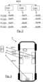
- the electronic unitis a BA beacon or a central electronic unit PE (also called central transmitter/receiver or “central transceiver”) as illustrated in the picture 3 .
- PEcentral transmitter/receiver
- three beacons BA1, BA2, BA3are used as illustrated in the picture 3 .
- the three beacons BA1, BA2, BA3are distributed all around the motor vehicle V, one right side and one left side of the motor vehicle (for example at each door) and one at the rear of the motor vehicle (for example in the trunk or tailgate of the motor vehicle V).
- eight beaconsare used. This allows to cover the corners of the motor vehicle V.
- the signals received by the user terminal SPare announcement frames ADV sent by the beacons BA.
- the processor PRO1is suitable for executing instructions for the implementation of scanning, storage, measurement steps (process P2 illustrated in figure 4 ) described later.
- the processor PRO2is suitable for executing instructions for the implementation of a broadcast step (process P1 illustrated on the figure 4 ) described later.
- the wireless communication module MC1 of the user terminal SPmakes it possible to establish a wireless link (here “Bluetooth Low Energy TM ”) with the wireless communication module MC2 of a beacon BA of the motor vehicle V.
- a wireless linkhere “Bluetooth Low Energy TM ”
- the MC2 wireless communication module of the BA beaconis suitable for be in broadcast mode (" advertising " mode in Bluetooth technology). In this case, it is suitable for broadcasting a plurality of ADV announcement frames within specific channels, called CA announcement channels (in English “ advertising channels ”) distinct from the data channels (in English: “ data channels ”) ) used to transmit application data exchange frames relating to established connections.
- the wireless communication module MC1 of the user terminal SPis adapted to be in a scanning mode (“ scanning ” mode in Bluetooth technology). For this purpose, it is adapted to scan said announcement channels CA to receive said broadcast announcement frames ADV. Scanning is sequential. He thus listens to an announcement channel, then another, etc. He listens to the announcement channels in order or out of order.
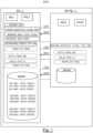
- the BLE protocolprovides 3 announcement channels CA1, CA2, CA3 illustrated on the figure 1 and the picture 2 , referenced channel 37, channel 38 and channel 39 according to the BLE protocol and having respective central frequencies equal to 2402 MHz, 2426 MHz, 2480 MHz, and 37 data channels (referenced channel 0 to channel 36).
- the three announcement channels CA1, CA2, CA3are distributed over a 2.4 GHz frequency band.
- the 3 announcement channels CA1, CA2, CA3respectively have central frequencies located at the lower end, in a central region and at the upper end of the frequency band concerned (here the 2.4 GHz band) .
- a beacon BAis adapted to broadcast a plurality of ad frames ADV within at least two ad channels CA, each broadcast ad frame AV comprising primary identification information FLG1 of a beacon BA.
- each broadcast AV announcement framecan also include secondary identification information FLG2 of the CA announcement channel used (function illustrated in figure 1 BRD(BA, ADV(FLG1, FLG2), PUtx, CA).
- three announcement channels CA1, CA2, CA3are used. This embodiment is taken as a non-limiting example for the rest of the description.
- a beacon BAis in a so-called non-connectable mode, it cannot establish a connection with the user terminal SP. It only broadcasts ADV announcement frames. It does not need to enter into connection with the user terminal SP.
- the primary identification information FLG1 and the secondary identification information FLG2allow the user terminal SP to sort and store an announcement frame ADV broadcast according to the beacon BA which broadcasts it, and the announcement channel CA used, namely on which it is broadcast.
- the primary identification information FLG1is a number between 1 and 3 assigned respectively to the beacon BA1, BA2 and BA3.
- the primary identification information FLG1makes it possible to differentiate the beacon BA which broadcasts an announcement frame ADV.
- the secondary identification information FLG2makes it possible to differentiate the announcement channel CA on which an announcement frame ADV is broadcast.
- the user terminal SPis suitable for scanning said at least three announcement channels CA1, CA2, CA3 (illustrated function SCN(SP, CA) illustrated in figure 1 ) to receive said ADV announcement frames (function RX(SP, ADV(FLG1, FLG2), CA) illustrated in figure 1 ).
- ADV announcement framesfunction RX(SP, ADV(FLG1, FLG2), CA
- the user terminal SPcan differentiate the various announcement frames ADV according to the beacon BA which broadcasts them and the announcement channel CA used for said broadcasting.
- the user terminal SPis thus adapted to memorize said announcement frames ADV by said user terminal SP according to said primary identification information FLG1 and said secondary identification information FLG2 (function illustrated on the figure 1 MEM(SP, ADV, FLG1, FLG2)).
- the user terminal SPis suitable for measuring the RSSI reception power of the memorized ADV announcement frames (function illustrated on the figure 1 MEAS(SP, ADV, RSSI)), namely the measurement of the RSSI reception power of the ADV announcement frames of each announcement channel CA broadcast by each beacon BA.
- RSSI reception power measurementor RSSI measurement will be used interchangeably.
- the user terminal SPperforms a measurement of the RSSI reception power of the ADV announcement frames received as mentioned above according to ⁇ a) to ⁇ i). It performs a sorting of these RSSI measurements according to the BA beacon which broadcasts the ADV announcement frame (thanks to the primary identification information FLG1) and the CA announcement channel used (thanks to the information of secondary identification FLG2).
- the transmission power PUtxvaries according to the announcement channels CA used for the same given distance D.
- the user terminal SPlistens to the three channels CA1, CA2, CA3, even if it does not not move and that it is at the same distance D, in a non-limiting example of 40cm, the measured reception power RSSI varies from one CA announcement channel to another.
- the user terminal SPperforms a first measurement of the power in reception RSSI11 on the announcement channel CA1, a second measurement of the power in reception RSSI12 on the announcement channel CA2, and a third reception power measurement RSSI13 on the announcement channel CA3, the three reception power measurements RSSI11, RSSI12, RSSI13 being different from each other.
- an announcement channel CAis taken as the reference channel CArf.
- the user terminal SPis also adapted to perform a dynamic normalization of the measurement of the power in reception RSSI of an announcement frame ADV of an announcement channel CA with respect to the measurement of the power in reception RSSIrf d 'an ADV announcement frame of the CArf reference channel according to an OFF compensation value (function illustrated on the figure 1 NORM(RSSI, RSSIrf, OFF, BA)). This normalization is described in more detail below.
- the distance D at which said user terminal SP of the motor vehicle V is locatedcan be determined for each beacon BA according to the measurements of the powers in reception RSSI (function illustrated in the figure 1 DET(D, RSSI, BA)), and in particular according to the standardized RSSI reception power measurements.
- This determinationis made according to a calibration curve which indicates, for a given distance value, what is the transmission power PUtx and what is the measurement of the corresponding RSSI reception power. It is recalled that when the transmitter is located at the same place as the receiver, the transmission power PUtx is equal to the reception power measurement RSSI. It is recalled that when the distance D is doubled, a loss substantially equal to ⁇ 8 db is observed for the RSSI reception power measurement.
- this determinationis made by the user terminal SP or by the central electronic unit PE of the motor vehicle V illustrated in the picture 3 .
- the position POS of the user terminal SP with respect to the motor vehicle Vis determined according to the distances D determined from each beacon BA (function illustrated in the figure 1 CAL(D,POS,V)).
- the position POSis determined according to a triangulation method well known to those skilled in the art. In a non-limiting embodiment, this determination is made by the user terminal SP or by the central electronic unit PE
- the central electronic unit PEis adapted to communicate with the user terminal SP via the BLE protocol.
- This central electronic unit PEis adapted to be in broadcast mode or in scanning mode. In addition to the broadcast frames, it can therefore exchange data frames on the 37 data channels with the user terminal SP.
- the user terminal SPis further adapted to send said power measurements in RSSI reception to said central electronic unit PE of said motor vehicle V so that it determines for each beacon BA the distance D at which said user terminal SP of the motor vehicle V is located (function illustrated in the figure 1 TX(SP, PE, RSSI)). This function being a non-limiting embodiment, it is illustrated in dotted lines on the figure 1 .
- the central electronic unit PEis also adapted to perform the dynamic normalization and/or the calculation of the position POS of the user terminal SP with respect to the motor vehicle V.
- the location system SYS describedthus makes it possible to implement the method of location P of a user terminal SP with respect to a motor vehicle V comprising a plurality of beacons BA, said user terminal SP and the beacons BA being adapted to communicate according to a Bluetooth Low Energy TM communication protocol.
- the user terminal SPperforms for each electronic unit BA the determination of the distance D at which said user terminal SP is located, the calculation of its position according to these determined distances D.
- each BA beaconbroadcasts a plurality of ADV announcement frames within at least two CA announcement channels, each broadcast ADV announcement frame comprising primary identification information FLG1 of a BA beacon and secondary identification FLG2 of the CA announcement channel used.
- the announcement frames ADV sent by the same beacon BA on the at least two announcement channels CAare identical, namely they include the same information INF apart from the secondary identification information FLG2.
- three announcement channels CA1, CA2, CA3are used.
- ADV announcement framesare broadcast regularly.
- a beacon BAthus sends the same announcement frame ADV several times on said at least three announcement channels CA.
- the broadcast by each BA beacon of an ADV announcement frame on said CA announcement channelsis carried out sequentially and according to a primary period T1.
- the primary period T1is substantially equal to 100 ms (milliseconds), plus or minus 10 ms. These 100ms make it possible to avoid a collision between the various ADV announcement frames broadcast.
- every 100 msthe same ADV announcement frame is broadcast on a different CA announcement channel.
- the broadcast of an ADV announcement frametakes place over a time substantially equal to 3 ms.
- a beacon BAsends over three primary periods T1, an announcement frame ADV on channel CA1, then the same announcement frame ADV on channel CA2, and finally the same announcement frame ADV on channel CA3.
- step 2)SCN(SP, CA)
- the user terminal SPscans said three announcement channels CA to receive said broadcast announcement frames ADV.
- CA paging channelsare scanned regularly.
- the scanning of the announcement channels CAis carried out according to a secondary period T2.
- the secondary period T2is equal to 5s (seconds).
- the primary period T1 for broadcasting the announcement frames ADV on the announcement channels CAis less than the secondary period T2 for scanning said announcement channels CA. This allows the user terminal SP to be sure of receiving the broadcast announcement frames ADV on a given announcement channel CA.
- the user terminal SPscans the three announcement channels CA1, CA2, CA3 over three secondary periods T2, the channel CA1, then the channel CA2, and finally the channel CA3.
- listening timemay vary. In a non-limiting embodiment, it is 4.99s. In a non-limiting embodiment, the difference between W2 and T2 can vary between 5ms and 10ms.
- the broadcasting by each BA beacon of the plurality of ADV announcement frames within the three CA announcement channels and the scanning of said three CA announcement channelsare desynchronized as can be see it on the figure 5 .
- the periods T1 and T2are not on the same scale.
- step 3) illustrated RX(SP, ADV(FLG1, FLG2), CA)the user terminal SP receives said broadcast announcement frames ADV.
- Each broadcast announcement frame ADVcomprises primary identification information FLG1 and secondary identification information FLG2 as described above.
- the user terminal SPstores said announcement frames ADV as a function of said primary identification information FLG1 and of said secondary identification information FLG2.
- step 5) illustrated MEAS(SP, ADV, RSSI)the user terminal SP measures the RSSI reception power of said stored ADV announcement frames.
- the user terminalcan perform for each announcement channel CA of each beacon BA a compensation of a measurement stored RSSI reception power.
- the user terminal SPcompares said power measured in RSSI reception with a theoretical power corresponding to a distance determined by means of a power regression curve as a function of distance (also called regression curve or RSSI curve "Received Signal Strength Indication”). On the abscissa, we find the distance (in centimeters), on the ordinate, we find the power (in decibels). If there is an offset between said measured power RSSI and said theoretical power, the user terminal SP compensates said measured power RSSI as a function of this offset.
- a regression curveis associated with each BA tag and each CA ad channel. In the non-limiting example of three beacons BA1, BA2 and BA3 and three announcement channels CA1, CA2, CA3, there are therefore six regression curves.
- the transmission power PUtx of the same announcement frame ADV broadcast by the same beacon BAvaries from one announcement channel CA to another CA for the same given distance D. Also, now that the announcement frames ADV have been sorted according to each announcement channel CA, to know precisely the distance D at which the user terminal SP is located with respect to the motor vehicle V, the next step is carried out.
- an announcement channel CAis taken as the reference channel CArf, and according to step 6) illustrated NORM(RSSI, RSSIrf, OFF, BA), the user terminal SP performs a dynamic normalization of the measurement of the RSSI reception power of an announcement frame ADV of an announcement channel CA with respect to the measurement of the power in reception RSSIrf of an announcement frame ADV of the reference channel CArf according to a compensation value OFF.
- the CArf reference channelis channel 37. It will be noted that this channel 37 is less used by other communication protocols (such as WIFI or ZigBee) which use the same frequency band at 2 .4GHz and therefore will have less interference. The RSSI reception power measurement will therefore be more reliable.
- the CArf reference channelis channel 38 or 39.
- the normalizationis performed each time the announcement channel CA changes, namely each time the user terminal SP scans a new announcement channel CA, and this for each beacon BA.
- There normalizationis thus dynamic since the compensation value OFF can vary on each change of announcement channel CA.
- the compensation value OFFis equal to the difference between the measurement of the power in reception RSSIrf of an ADV announcement frame of the reference channel CArf and the measurement of the measurement of the RSSI reception power of an ADV announcement frame of a CA announcement channel.
- the OFF compensation valueis equal to +21 db.
- the RSSI reception power measurements of +21dbwe add +21db to -85db. We then obtain -64db.
- the OFF compensation valueis equal to +3db.
- the location method Pcan further comprise a static calibration of the measurements of the RSSI reception power of the ADV announcement frames broadcast on the three announcement channels 37, 38, 39.
- This calibration staticcan be done according to the gain of the BLE antennas of the communication modules MC2 of the BA beacons which can be different and/or according to the path traveled by the radio waves emitted by said antennas to send said ADV announcement frames etc.
- the distance D at which said user terminal SP of the motor vehicle V is locatedis determined according to the measurements of the powers in reception RSSI, and more particularly according to the measurements of the standardized RSSI reception powers. This determination is made for each BA beacon. Thus, in the non-limiting example given, there will be three determined distances D.
- the measurements of the normalized RSSI reception powersare substantially equal to ⁇ 64 db i.
- this determinationis made by the user terminal SP as illustrated in the figure 4 .
- the user terminal SPcalculates its position POS with respect to the motor vehicle V as a function of the distances D determined with respect to each beacon BA. For this purpose, the calculation of the position is carried out by triangulation
- the triangulationmakes it possible to have a more precise location of the user terminal SP.
- step 9) illustrated TX(SP, PE, POS)the user terminal SP sends the calculated position POS to the central electronic unit PE, which receives it according to step 10) illustrated RX(PE, SP, POS) .
- step 11ACTV(Fct), depending on the position POS thus calculated, the function Fct is activated or not.
- the activation of said Fct functionis performed by the central electronic unit PE.
- the location process Pmakes it possible to determine the distance D to which is the user terminal SP relative to the motor vehicle V, precisely.
- steps 6, 7, 8can be performed by the central electronic unit PE.
- the location method Pfurther comprises the sending by the user terminal SP of said RSSI reception power measurements to said central electronic unit PE for that it determines for each beacon BA the distance D at which said user terminal SP of the motor vehicle V is located.
- the BA beaconsare positioned in the tires, they can be used for a TPMS application called “Tire Pressure Monitoring System” which gives information on the pressure of the tire.
- the function Fct executedis automatic parking of the motor vehicle V.
Landscapes
- Engineering & Computer Science (AREA)
- Physics & Mathematics (AREA)
- General Physics & Mathematics (AREA)
- Radar, Positioning & Navigation (AREA)
- Remote Sensing (AREA)
- Computer Networks & Wireless Communication (AREA)
- Mechanical Engineering (AREA)
- Mobile Radio Communication Systems (AREA)
- Position Fixing By Use Of Radio Waves (AREA)
Description
Translated fromFrenchLa présente invention concerne un procédé de localisation d'un terminal utilisateur par rapport à un véhicule automobile.The present invention relates to a method for locating a user terminal with respect to a motor vehicle.
La présente invention concerne également un système de localisation d'un terminal utilisateur par rapport à un véhicule automobile associé.The present invention also relates to a system for locating a user terminal with respect to an associated motor vehicle.
Elle trouve une application particulière mais non limitative dans le domaine des véhicules automobiles.It finds a particular but non-limiting application in the field of motor vehicles.
Dans le domaine des véhicules automobiles, il existe des procédés de localisation d'un terminal utilisateur par rapport à un véhicule automobile. Ces systèmes sont basés sur échanges entre une ou plusieurs unités disposées dans le véhicule et le terminal utilisateur.In the field of motor vehicles, there are methods for locating a user terminal with respect to a motor vehicle. These systems are based on exchanges between one or more units arranged in the vehicle and the user terminal.
Il est connu pour cette localisation d'utiliser des échanges du type basse fréquence ou du type ultra large bande, ultra wide band (UWB) en anglais.It is known for this localization to use exchanges of the low frequency type or of the ultra wide band type, ultra wide band (UWB) in English.
Lorsque le terminal utilisateur est du type smartphone, ce type d'échange n'est pas disponible en standard, et il est donc nécessaire en plus des dispositifs à installer sur le véhicule, de transformer le terminal utilisateur.When the user terminal is of the smartphone type, this type of exchange is not available as standard, and it is therefore necessary, in addition to the devices to be installed on the vehicle, to transform the user terminal.
La publication de demande de brevet
A cette fin l'invention propose un procédé de localisation d'un terminal utilisateur par rapport à un véhicule automobile comprenant une pluralité de d'unités électroniques selon la revendication 1.To this end, the invention proposes a method for locating a user terminal with respect to a motor vehicle comprising a plurality of electronic units according to
Ainsi, comme on le verra en détail par la suite, grâce à l'information d'identification secondaire, on peut faire le tri entre les trames d'annonce diffusées pour chaque canal d'annonce de chaque unité électronique. Cela va permettre d'avoir une mesure de puissance en réception de chaque trame d'annonce précise.Thus, as will be seen in detail below, thanks to the secondary identification information, it is possible to sort between the announcement frames broadcast for each announcement channel of each electronic unit. This will make it possible to have a power measurement in reception of each precise announcement frame.
Selon un mode de réalisation non limitatif, pour chaque unité électronique, un canal d'annonce est pris comme canal de référence et le procédé de localisation comprend en outre :
- une normalisation dynamique de la mesure de la puissance en réception d'une trame d'annonce d'un canal d'annonce par rapport à la mesure de la puissance en réception d'une trame d'annonce du canal de référence en fonction d'une valeur de compensation.
- a dynamic normalization of the receive power measurement of an announcement frame of an announcement channel relative to the receive power measurement of an announcement frame of the reference channel as a function of a compensation value.
Selon un mode de réalisation non limitatif, ladite information d'identification secondaire est un compteur, ledit compteur étant incrémenté en fonction du canal d'annonce utilisé.According to a non-limiting embodiment, said secondary identification information is a counter, said counter being incremented according to the announcement channel used.
Selon un mode de réalisation non limitatif, lesdits au moins deux canaux d'annonce sont répartis sur une bande de fréquence de 2,4GHz.According to a non-limiting embodiment, said at least two announcement channels are distributed over a 2.4 GHz frequency band.
Selon un mode de réalisation non limitatif, le véhicule automobile comprend au moins deux unités électroniques.According to a non-limiting embodiment, the motor vehicle comprises at least two electronic units.
Selon un mode de réalisation non limitatif, ledit balayage desdits au moins deux canaux d'annonce s'effectue de façon séquentielle et selon une période secondaire.According to a non-limiting embodiment, said scanning of said at least two announcement channels is carried out sequentially and according to a secondary period.
Selon un mode de réalisation non limitatif, la diffusion par chaque unité électronique d'une trame d'annonce sur lesdits au moins deux canaux d'annonce s'effectue de façon séquentielle et selon une période primaire inférieure à ladite période secondaire.According to a non-limiting embodiment, the broadcast by each unit electronics of an announcement frame on said at least two announcement channels takes place sequentially and according to a primary period less than said secondary period.
Selon un mode de réalisation non limitatif, la période primaire est sensiblement égale à cent millisecondes.According to a non-limiting embodiment, the primary period is substantially equal to one hundred milliseconds.
Selon un mode de réalisation non limitatif, selon lequel la période secondaire est sensiblement égale à cinq secondes.According to a non-limiting embodiment, according to which the secondary period is substantially equal to five seconds.
Selon un mode de réalisation non limitatif, le terminal utilisateur est un téléphone mobile, un identifiant, un badge, une tablette.According to a non-limiting embodiment, the user terminal is a mobile telephone, an identifier, a badge, a tablet.
Selon un mode de réalisation non limitatif, ladite unité électronique est une balise.According to a non-limiting embodiment, said electronic unit is a beacon.
Selon un mode de réalisation non limitatif, la détermination de ladite distance et/ou le calcul de la position du terminal utilisateur est effectuée par ledit terminal utilisateur ou une unité électronique dudit véhicule automobile.According to a non-limiting embodiment, the determination of said distance and/or the calculation of the position of the user terminal is performed by said user terminal or an electronic unit of said motor vehicle.
Il est également proposé un procédé de diffusion défini selon la revendication 13.There is also provided a method of broadcasting defined in claim 13.
Il est également proposé un terminal utilisateur défini selon la revendication 14.There is also provided a user terminal defined in
Selon un mode de réalisation non limitatif, ledit terminal utilisateur est en outre adapté pour :
- pour chaque unité électronique, déterminer la distance à laquelle se trouve ledit terminal utilisateur du véhicule automobile en fonction desdites mesures de puissances en réception et calculer la position du terminal utilisateur par rapport au véhicule automobile en fonction des distances déterminées pour chaque unité électronique ; ou
- envoyer lesdites mesures de puissances en réception à une unité électronique dudit véhicule automobile.
- for each electronic unit, determining the distance at which said user terminal is located from the motor vehicle according to said reception power measurements and calculating the position of the user terminal relative to the motor vehicle according to the distances determined for each electronic unit; Or
- sending said power measurements in reception to an electronic unit of said motor vehicle.
Selon un mode de réalisation non limitatif, pour chaque unité électronique un canal d'annonce est pris comme canal de référence et selon lequel ledit terminal utilisateur est en outre adapté pour effectuer une normalisation dynamique de la mesure de la puissance en réception d'une trame d'annonce d'un canal d'annonce par rapport à la mesure de la puissance en réception d'une trame d'annonce du canal de référence en fonction d'une valeur de compensation.According to a non-limiting embodiment, for each electronic unit an announcement channel is taken as the reference channel and according to which said user terminal is further adapted to carry out a dynamic normalization of the measurement of the power in reception of a frame of an announcement channel with respect to the measurement of the power in reception of an announcement frame of the reference channel as a function of a compensation value.
Il est également proposé une unité électronique définie selon la revendication 17.There is also provided an electronic unit defined in claim 17.
L'invention et ses différentes applications seront mieux comprises à la lecture de la description qui suit et à l'examen des figures qui l'accompagnent.
- la
figure 1 représente un schéma d'un système de localisation d'un terminal utilisateur par rapport à un véhicule automobile adapté pour mettre en oeuvre un procédé de localisation, selon un mode de réalisation non limitatif de l'invention, ledit système de localisation comprenant une pluralité d'unités électroniques ; - la
figure 2 représente un schéma de trois canaux sur lesquels une trame d'annonce peut être diffusée selon le procédé de localisation de lafigure 1 , une trame d'annone comprenant une information d'identification secondaire du canal utilisé selon différents modes de réalisation non limitatif ; - la
figure 3 représente un schéma d'un véhicule automobile comprenant une pluralité d'unités électroniques et d'un terminal utilisateur adapté pour recevoir des trames d'annonce à partir desdites unités électroniques; - la
figure 4 représente un schéma d'un procédé de localisation d'un terminal utilisateur par rapport à un véhicule automobile selon un mode de réalisation non limitatif de l'invention et mis en oeuvre par le système de localisation de lafigure 1 ; - la
figure 5 représente un schéma illustrant la diffusion de trames d'annonce sur trois canaux différents et de leur réception par un terminal utilisateur selon le procédé de localisation de lafigure 4 , selon un mode de réalisation non limitatif ; et - la
figure 6 représente un schéma de trames d'annonces diffusée par une unité électronique et reçues par un terminal utilisateur et de leur mesure de puissance en réception réalisée selon le procédé de localisation de lafigure 4 , selon un mode de réalisation non limitatif.
- there
figure 1 represents a diagram of a system for locating a user terminal with respect to a motor vehicle suitable for implementing a method of locating, according to a non-limiting embodiment of the invention, said locating system comprising a plurality of electronic units; - there
picture 2figure 1 , an annona frame comprising secondary identification information of the channel used according to various non-limiting embodiments; - there
picture 3 - there
figure 4 represents a diagram of a method for locating a user terminal with respect to a motor vehicle according to a non-limiting embodiment of the invention and implemented by the system location of thefigure 1 ; - there
figure 5 represents a diagram illustrating the broadcasting of announcement frames on three different channels and their reception by a user terminal according to the method of locating thefigure 4 , according to a non-limiting embodiment; And - there
figure 6 represents a diagram of announcement frames broadcast by an electronic unit and received by a user terminal and of their power measurement in reception carried out according to the method of locating thefigure 4 , according to a non-limiting embodiment.
Les éléments identiques, par structure ou par fonction, apparaissant sur différentes figures conservent, sauf précision contraire, les mêmes références.Identical elements, by structure or by function, appearing in different figures retain, unless otherwise specified, the same references.
L'invention concerne un procédé de localisation P d'un terminal utilisateur SP par rapport à un véhicule automobile V et un système de localisation SYS associé.The invention relates to a method for locating P a user terminal SP relative to a motor vehicle V and an associated location system SYS.
Le procédé localisation P est mis en oeuvre par le système de localisation SYS d'un terminal utilisateur SP par rapport à un véhicule automobile V comprenant une pluralité d'unités électroniques BA, PE, ledit terminal utilisateur SP et les unités électroniques BA, PE étant adaptés pour communiquer selon un protocole de communication Bluetooth Low Energy™ référencé BLE. Le protocole BLE permet un échange bidirectionnel de données à très courte distance. Il utilise des ondes radio dite RF sur une bande de fréquence de 2,4GH.The location method P is implemented by the location system SYS of a user terminal SP with respect to a motor vehicle V comprising a plurality of electronic units BA, PE, said user terminal SP and the electronic units BA, PE being adapted to communicate according to a Bluetooth Low Energy™ communication protocol referenced BLE. The BLE protocol allows two-way data exchange over very short distances. It uses so-called RF radio waves on a 2.4GH frequency band.
La
Le système SYS comprend :
- une pluralité d'unités électroniques BA, PE. Sur la
figure 1 , une unité électronique BA, PE est représentée ; et - ledit terminal utilisateur SP.
- a plurality of electronic units BA, PE. On the
figure 1 , an electronic unit BA, PE is represented; And - said user terminal SP.
Pour la suite de la description, on utilisera le terme appareil pour indiquer un terminal utilisateur SP ou une unité électronique BA, PE.For the remainder of the description, the term device will be used to indicate a user terminal SP or an electronic unit BA, PE.
Les éléments dudit système SYS sont décrits en détail ci-après.The elements of said system SYS are described in detail below.
Un utilisateur peut contrôler l'exécution d'une fonction Fct au moyen du terminal utilisateur SP. Dans des modes de réalisation non limitatifs, la fonction Fct est un verrouillage/déverrouillage du véhicule automobile V pour accéder audit véhicule automobile V ou un démarrage du véhicule automobile V.A user can control the execution of an Fct function by means of the user terminal SP. In non-limiting embodiments, the function Fct is a locking/unlocking of the motor vehicle V to access said motor vehicle V or a starting of the motor vehicle V.
Dans des exemples non limitatifs, le terminal utilisateur SP est identifiant, un badge, une tablette, un téléphone mobile tel que dans un exemple non limitatif un téléphone dit intelligent (« Smartphone en anglais») utilisé par un utilisateur du véhicule automobile V.In non-limiting examples, the user terminal SP is an identifier, a badge, a tablet, a mobile telephone such as in a non-limiting example a so-called smart telephone (“Smartphone in English”) used by a user of the motor vehicle V.
Dans un mode de réalisation non limitatif, le terminal utilisateur SP utilise la technologie Bluetooth Low Energy™ pour communiquer avec le véhicule automobile V, que ce soit pour l'accès au véhicule, c'est-à-dire pour ouvrir/fermer un ouvrant du véhicule (portière ou coffre), ou pour le démarrage du véhicule. La procédure d'accès à un véhicule automobile ou de démarrage via un terminal utilisateur SP étant bien connue de l'homme du métier, elle n'est pas décrite ici.In a non-limiting embodiment, the user terminal SP uses Bluetooth Low Energy™ technology to communicate with the motor vehicle V, whether for access to the vehicle, that is to say to open/close an opening of the vehicle (door or trunk), or for the starting the vehicle. Since the procedure for accessing or starting a motor vehicle via a user terminal SP is well known to those skilled in the art, it is not described here.
Pour des raisons de sécurité, l'exécution d'une fonction Fct du véhicule automobile V est conditionnée par la localisation du terminal utilisateur SP par rapport au véhicule automobile V, à savoir par la distance D à laquelle il se trouve par rapport au véhicule automobile V. Dans un exemple non limitatif, le déverrouillage du véhicule automobile V peut s'effectuer lorsque le terminal utilisateur SP se trouve proche du véhicule automobile V, à une distance sensiblement égale à 50cm (centimètres).For security reasons, the execution of a function Fct of the motor vehicle V is conditioned by the location of the user terminal SP with respect to the motor vehicle V, namely by the distance D at which it is located with respect to the motor vehicle V. In a non-limiting example, the unlocking of the motor vehicle V can take place when the user terminal SP is close to the motor vehicle V, at a distance substantially equal to 50 cm (centimeters).
La mesure d'une distance D entre le terminal utilisateur SP et le véhicule automobile V s'effectue au moyen de la mesure de la puissance d'un signal reçu dont la puissance initiale est connue à savoir la puissance à l'émission dudit signal est connue, ce qui permet de déduire la distance entre l'émetteur et le récepteur. L'émetteur est ici une unité électronique BA, PE du véhicule automobile V et le récepteur est le terminal utilisateur SP.The measurement of a distance D between the user terminal SP and the motor vehicle V is carried out by means of the measurement of the power of a received signal whose initial power is known, namely the power on transmission of said signal is known, which makes it possible to deduce the distance between the transmitter and the receiver. The transmitter is here an electronic unit BA, PE of the motor vehicle V and the receiver is the user terminal SP.
On appelle cette méthode mesure par RSSI (en anglais « Received Signal Strength Indication »). Pour améliorer la mesure de la distance, on utilise une pluralité d'unités électroniques BA, PE et une triangulation est réalisée sur les différentes mesures de puissance des signaux reçus.This method is called RSSI (Received Signal Strength Indication) measurement. To improve the measurement of the distance, a plurality of electronic units BA, PE are used and a triangulation is carried out on the various power measurements of the signals received.
Dans un mode de réalisation non limitatif, l'unité électronique est une balise BA ou une unité électronique centrale PE (appelée également émetteur/récepteur central ou « central transceiver » en anglais) tel qu'illustré sur la
Dans un mode de réalisation non limitatif pris dans la suite de la description, trois balises BA1, BA2, BA3 sont utilisées tel qu'illustré sur la
Comme on va le voir ci-après, les signaux reçus par le terminal utilisateur SP sont des trames d'annonce ADV envoyées par les balises BA.As will be seen below, the signals received by the user terminal SP are announcement frames ADV sent by the beacons BA.
Tel qu'illustré sur la
- un module de communication sans fil MC1. Un module de communication sans fil MC1 comprend ainsi une antenne BLE qui sert d'émetteur/récepteur ;
- une unité de mémorisation MEM1. Dans un exemple non limitatif, l'unité de mémorisation est une mémoire non-volatile réinscriptible EEPROM ;
- un processeur PRO1.
- a wireless communication module MC1. A wireless communication module MC1 thus comprises a BLE antenna which serves as a transmitter/receiver;
- a storage unit MEM1. In a non-limiting example, the storage unit is a rewritable non-volatile memory EEPROM;
- a PRO1 processor.
Le processeur PRO1 est adapté pour exécuter des instructions pour la mise en oeuvre d'étapes de balayage, mémorisation, mesure (procédé P2 illustré sur la
Une balise BA comprend :
- un module de communication sans fil MC2. Un module de communication sans fil MC2 comprend ainsi une antenne BLE qui sert d'émetteur/récepteur ;
- une unité de mémorisation MEM2. Dans un exemple non limitatif, l'unité de mémorisation est une mémoire non-volatile réinscriptible EEPROM ;
- un processeur PRO2.
- an MC2 wireless communication module. A wireless communication module MC2 thus comprises a BLE antenna which serves as a transmitter/receiver;
- a storage unit MEM2. In a non-limiting example, the storage unit is a rewritable non-volatile memory EEPROM;
- a PRO2 processor.
Le processeur PRO2 est adapté pour exécuter des instructions pour la mise en oeuvre d'une étape de diffusion (procédé P1 illustré sur la
Le module de communication sans fil MC1 du terminal utilisateur SP permet d'établir une liaison sans fil (ici « Bluetooth Low Energy™») avec le module de communication sans fil MC2 d'une balise BA du véhicule automobile V.The wireless communication module MC1 of the user terminal SP makes it possible to establish a wireless link (here “Bluetooth Low Energy™ ”) with the wireless communication module MC2 of a beacon BA of the motor vehicle V.
Le module de communication sans fil MC2 de la balise BA est adapté pour être dans un mode diffusion (mode "advertising" en technologie Bluetooth). Dans ce cas, il est adapté pour diffuser une pluralité de trames d'annonce ADV au sein de canaux spécifiques, dits canaux d'annonce CA (en anglais "advertising channels") distincts des canaux de données (en anglais : "data channels") utilisés pour transmettre des trames d'échange de données applicatives relatives à des connexions établies.The MC2 wireless communication module of the BA beacon is suitable for be in broadcast mode ("advertising " mode in Bluetooth technology). In this case, it is suitable for broadcasting a plurality of ADV announcement frames within specific channels, called CA announcement channels (in English "advertising channels ") distinct from the data channels (in English: "data channels ") ) used to transmit application data exchange frames relating to established connections.
Le module de communication sans fil MC1 du terminal utilisateur SP est adapté pour être dans un mode balayage (mode "scanning" en technologie Bluetooth). A cet effet, il est adapté pour effectuer un balayage desdits canaux d'annonce CA pour recevoir lesdites trames d'annonce ADV diffusées. Le balayage est séquentiel. Il écoute ainsi un canal d'annonce, puis un autre etc. Il écoute dans l'ordre les canaux d'annonce ou dans le désordre.The wireless communication module MC1 of the user terminal SP is adapted to be in a scanning mode (“scanning ” mode in Bluetooth technology). For this purpose, it is adapted to scan said announcement channels CA to receive said broadcast announcement frames ADV. Scanning is sequential. He thus listens to an announcement channel, then another, etc. He listens to the announcement channels in order or out of order.
Le protocole BLE prévoit 3 canaux d'annonce CA1, CA2, CA3 illustrés sur la
Une balise BA est adaptée pour diffuser une pluralité de trames d'annonce ADV au sein d'au moins deux canaux d'annonce CA chaque trame d'annonce AV diffusée comprenant une information d'identification primaire FLG1 d'une balise BA.A beacon BA is adapted to broadcast a plurality of ad frames ADV within at least two ad channels CA, each broadcast ad frame AV comprising primary identification information FLG1 of a beacon BA.
Dans un mode de réalisation avantageux chaque trame d'annonce AV diffusée peut également comprendre une information d'identification secondaire FLG2 du canal d'annonce CA utilisé (fonction illustrée sur la
Dans un mode de réalisation non limitatif, trois canaux d'annonce CA1, CA2, CA3 sont utilisés. Ce mode de réalisation est pris comme exemple non limitatif pour la suite de la description.In a non-limiting embodiment, three announcement channels CA1, CA2, CA3 are used. This embodiment is taken as a non-limiting example for the rest of the description.
Ainsi, tel qu'illustré sur la
- la balise BA1 est adaptée pour diffuser une pluralité de trames d'annonce ADV1 sur les trois canaux d'annonce CA1, CA2 et CA3 ;
- la balise BA2 est adaptée pour diffuser une pluralité de trames d'annonce ADV2 sur les trois canaux d'annonce CA1, CA2 et CA3 ; et
- la balise BA3 est adaptée pour diffuser une pluralité de trames d'annonce ADV3 sur les trois canaux d'annonce CA1, CA2, CA3 illustrés sur la
figure 2 .
- the BA1 beacon is adapted to broadcast a plurality of announcement frames ADV1 on the three announcement channels CA1, CA2 and CA3;
- the BA2 beacon is adapted to broadcast a plurality of ad frames ADV2 on the three ad channels CA1, CA2 and CA3; And
- the BA3 beacon is adapted to broadcast a plurality of announcement frames ADV3 on the three announcement channels CA1, CA2, CA3 illustrated on the
figure 2 .
Une balise BA envoie ainsi plusieurs fois une même trame d'annonce ADV séquentiellement sur les trois canaux d'annonce CA1, CA2, CA3. Elle peut le faire dans l'ordre des canaux d'annonce CA1, CA2, CA3 ou dans le désordre. Outre les informations d'identification primaire FLG1 et secondaire FLG2, cette trame d'annonce ADV comporte des informations INF qui indiquent :
- que la balise BA est connectable ou non avec un autre appareil ;
- la puissance à l'émission PUtx de la trame d'annonce ADV ;
- la position de la balise BA sur le véhicule automobile V. Dans des exemples non limitatifs, la position est :
- avant droit au niveau d'une portière ;
- avant gauche au niveau d'une portière ;
- arrière droite au niveau d'une portière ;
- arrière gauche au niveau d'une portière ;
- à l'arrière au niveau du coffre ou du hayon ;
- avant droit au niveau d'un pneu ;
- avant gauche au niveau d'un pneu;
- arrière droite au niveau d'un pneu;
- arrière gauche au niveau d'un pneu etc.
- whether or not the BA beacon can be connected with another device;
- the transmission power PUtx of the announcement frame ADV;
- the position of the BA beacon on the motor vehicle V. In non-limiting examples, the position is:
- front right at a door;
- front left at a door;
- rear right at a door;
- rear left at a door;
- at the rear in the boot or tailgate;
- front right at tire level;
- left front at tire level;
- rear right at tire level;
- rear left at a tire etc.
Les trames d'annonce ADV étant connues de l'homme du métier, elles ne sont pas décrites plus en détail.As the ADV announcement frames are known to those skilled in the art, they are not described in more detail.
Dans un mode de réalisation non limitatif, une balise BA est dans un mode dit non connectable, elle ne peut établir de connexion avec le terminal utilisateur SP. Elle se contente de diffuser des trames d'annonce ADV. Elle n'a pas besoin d'entrer en connexion avec le terminal utilisateur SP.In a non-limiting embodiment, a beacon BA is in a so-called non-connectable mode, it cannot establish a connection with the user terminal SP. It only broadcasts ADV announcement frames. It does not need to enter into connection with the user terminal SP.
L'information d'identification primaire FLG1 et l'information d'identification secondaire FLG2 permettent au terminal utilisateur SP de trier et mémoriser une trame d'annonce ADV diffusée en fonction de la balise BA qui la diffuse, et du canal d'annonce CA utilisé, à savoir sur laquelle elle est diffusée.The primary identification information FLG1 and the secondary identification information FLG2 allow the user terminal SP to sort and store an announcement frame ADV broadcast according to the beacon BA which broadcasts it, and the announcement channel CA used, namely on which it is broadcast.
Dans un mode de réalisation non limitatif, l'information d'identification primaire FLG1 est un nombre entre 1 et 3 attribué respectivement à la balise BA1, BA2 et BA3. Ainsi, l'information d'identification primaire FLG1 permet de différencier la balise BA qui diffuse une trame d'annonce ADV.In a non-limiting embodiment, the primary identification information FLG1 is a number between 1 and 3 assigned respectively to the beacon BA1, BA2 and BA3. Thus, the primary identification information FLG1 makes it possible to differentiate the beacon BA which broadcasts an announcement frame ADV.
Dans un mode de réalisation non limitatif, l'information d'identification secondaire FLG2 est un compteur, ledit compteur étant incrémenté en fonction du canal d'annonce CA utilisé. On a ainsi un octet dédié à cet effet dans la trame d'annonce ADV. Ainsi, comme on peut le voir sur la
- le compteur FLG2 est initialisé à 0 et incrémenté de 1 pour le canal suivant. L'information d'indentification secondaire FLG2 est donc égale à 0x00 en hexadécimal pour le canal CA1, 0x01 pour le canal CA2 et 0x02 pour le canal CA3 ; ou
- le compteur FLG2 est initialisé à 1 et incrémenté de 1 pour le canal suivant. L'information d'indentification secondaire FLG2 est donc égale à 0x01 en hexadécimal pour le canal CA1, 0x02 pour le canal CA2 et 0x03 pour le canal CA3 ; ou
- le compteur FLG2 est initialisé à 1 et incrémenté de 1 pour le canal suivant
puis 2 pour le canal suivant. L'information d'indentification secondaire FLG2 est donc égale à 0x01 en hexadécimal pour le canal CA1, 0x02 pour le canal CA2 et 0x04 pour le canal CA3 ; ou - le compteur FLG2 est initialisé à 4 et incrémenté de 1 pour le canal suivant. L'information d'indentification secondaire FLG2 est donc égale à 0x04 pour le canal CA1, 0x05 pour le canal CA2 et 0x06 pour le canal CA3.
- counter FLG2 is initialized at 0 and incremented by 1 for the next channel. The secondary identification information FLG2 is therefore equal to 0x00 in hexadecimal for the channel CA1, 0x01 for the channel CA2 and 0x02 for the channel CA3; Or
- counter FLG2 is initialized at 1 and incremented by 1 for the next channel. The secondary identification information FLG2 is therefore equal to 0x01 in hexadecimal for the channel CA1, 0x02 for the channel CA2 and 0x03 for the channel CA3; Or
- counter FLG2 is initialized at 1 and incremented by 1 for the next channel then 2 for the next channel. The secondary identification information FLG2 is therefore equal to 0x01 in hexadecimal for the channel CA1, 0x02 for the channel CA2 and 0x04 for the channel CA3; Or
- the FLG2 counter is initialized to 4 and incremented by 1 for the channel following. The secondary identification information FLG2 is therefore equal to 0x04 for the channel CA1, 0x05 for the channel CA2 and 0x06 for the channel CA3.
Ainsi, l'information d'identification secondaire FLG2 permet de différencier le canal d'annonce CA sur laquelle une trame d'annonce ADV est diffusée.Thus, the secondary identification information FLG2 makes it possible to differentiate the announcement channel CA on which an announcement frame ADV is broadcast.
Le terminal utilisateur SP est adapté pour balayer lesdits au moins trois canaux d'annonce CA1, CA2, CA3 (fonction illustrée SCN(SP, CA) illustrée à la
Le terminal utilisateur SP est ainsi adapté pour mémoriser lesdites trames d'annonce ADV par ledit terminal utilisateur SP en fonction de ladite information d'identification primaire FLG1 et de ladite information d'identification secondaire FLG2 (fonction illustrée sur la
Ainsi, tel qu'illustré sur la
- a) les trames d'annonce ADV1 reçues de la balise BA1 sur le canal CA1 ;
- b) les trames d'annonce ADV2 reçues de la balise BA2 sur le canal CA1 ;
- c) les trames d'annonce ADV3 reçues de la balise BA3 sur le canal CA1 ;
- d) les trames d'annonce ADV1 reçues de la balise BA1 sur le canal CA2 ;
- e) les trames d'annonce ADV2 reçues de la balise BA2 sur le canal CA2 ;
- f) les trames d'annonce ADV3 reçues de la balise BA3 sur le canal CA2 ;
- g) les trames d'annonce ADV1 reçues de la balise BA1 sur le canal CA3 ;
- h) les trames d'annonce ADV2 reçues de la balise BA2 sur le canal CA3 ;
- i) les trames d'annonce ADV3 reçues de la balise BA3 sur le canal CA3.
- a) the ADV1 announcement frames received from the BA1 beacon on the CA1 channel;
- b) the ADV2 announcement frames received from the BA2 beacon on the CA1 channel;
- c) the ADV3 announcement frames received from the BA3 beacon on the CA1 channel;
- d) the ADV1 announcement frames received from the BA1 beacon on the CA2 channel;
- e) the ADV2 announcement frames received from the BA2 beacon on the CA2 channel;
- f) the ADV3 announcement frames received from the BA3 beacon on the CA2 channel;
- g) the ADV1 announcement frames received from the BA1 beacon on the CA3 channel;
- h) the ADV2 announcement frames received from the BA2 beacon on the CA3 channel;
- i) the ADV3 announcement frames received from the BA3 beacon on the CA3 channel.
Le terminal utilisateur SP est adapté pour mesurer la puissance en réception RSSI des trames d'annonce ADV mémorisées (fonction illustrée sur la
Ainsi, le terminal utilisateur SP effectue une mesure de la puissance en réception RSSI des trames d'annonces ADV reçues telles que mentionnées précédemment selon les §a) à §i). Il effectue un tri de ces mesures RSSI en fonction de la balise BA qui diffuse la trame d'annonce ADV (grâce à l'information d'identification primaire FLG1) et du canal d'annonce CA utilisé (grâce à l'information d'identification secondaire FLG2).Thus, the user terminal SP performs a measurement of the RSSI reception power of the ADV announcement frames received as mentioned above according to §a) to §i). It performs a sorting of these RSSI measurements according to the BA beacon which broadcasts the ADV announcement frame (thanks to the primary identification information FLG1) and the CA announcement channel used (thanks to the information of secondary identification FLG2).
Ainsi tel qu'illustré sur la
- A) pour la balise BA1 :
- pour le canal CA1, une mesure de puissance en réception RSS11 ;
- pour le canal CA2, une mesure de puissance en réception RSS12 ;
- pour le canal CA3, une mesure de puissance en réception RSS13.
- B) pour la balise BA2 :
- pour le canal CA1, une mesure de puissance en réception RSS21 ;
- pour le canal CA2, une mesure de puissance en réception RSS22 ;
- pour le canal CA3, une mesure de puissance en réception RSS23.
- C) pour la balise BA3 :
- pour le canal CA1, une mesure de puissance en réception RSS31 ;
- pour le canal CA2, une mesure de puissance en réception RSS32 ;
- pour le canal CA3, une mesure de puissance en réception RSS33.
- A) for the BA1 beacon:
- for the channel CA1, a power measurement in reception RSS11;
- for the channel CA2, a power measurement in reception RSS12;
- for channel CA3, an RSS13 reception power measurement.
- B) for the BA2 beacon:
- for channel CA1, a reception power measurement RSS21;
- for the channel CA2, a power measurement in reception RSS22;
- for channel CA3, an RSS23 reception power measurement.
- C) for the BA3 beacon:
- for channel CA1, a reception power measurement RSS31;
- for the channel CA2, a power measurement in reception RSS32;
- for channel CA3, an RSS33 reception power measurement.
On notera que la puissance à l'émission PUtx varie selon les canaux d'annonce CA utilisé pour une même distance D donnée. Aussi, lorsque le terminal utilisateur SP écoute les trois canaux CA1, CA2, CA3, même s'il ne bouge pas et qu'il est à une même distance D, dans un exemple non limitatif de 40cm, la puissance en réception mesurée RSSI varie d'un canal d'annonce CA à un autre. Ainsi, par exemple pour une même trame d'annonce ADV1 envoyée par la balise BA1, le terminal utilisateur SP effectue une première mesure de la puissance en réception RSSI11 sur le canal d'annonce CA1, une deuxième mesure de la puissance en réception RSSI12 sur le canal d'annonce CA2, et une troisième mesure de la puissance en réception RSSI13 sur le canal d'annonce CA3, les trois mesures de la puissances en réception RSSI11, RSSI12, RSSI13 étant différentes les unes des autres.It will be noted that the transmission power PUtx varies according to the announcement channels CA used for the same given distance D. Also, when the user terminal SP listens to the three channels CA1, CA2, CA3, even if it does not not move and that it is at the same distance D, in a non-limiting example of 40cm, the measured reception power RSSI varies from one CA announcement channel to another. Thus, for example, for the same announcement frame ADV1 sent by the beacon BA1, the user terminal SP performs a first measurement of the power in reception RSSI11 on the announcement channel CA1, a second measurement of the power in reception RSSI12 on the announcement channel CA2, and a third reception power measurement RSSI13 on the announcement channel CA3, the three reception power measurements RSSI11, RSSI12, RSSI13 being different from each other.
Ainsi, sans l'information d'identification secondaire FLG2, même si le terminal utilisateur SP se trouve à une distance donnée D, il ne serait pas possible de savoir précisément à quelle distance il se trouve par rapport au véhicule automobile V, car en raison de la dispersion des puissances à l'émission PUtx et donc des mesures de la puissance en réception RSSI, on pourrait croire que le terminal utilisateur SP bouge et que la distance D à laquelle il se trouve du véhicule automobile V varie.Thus, without the secondary identification information FLG2, even if the user terminal SP is at a given distance D, it would not be possible to know precisely at what distance it is from the motor vehicle V, because due to from the dispersion of the powers at transmission PUtx and therefore from the measurements of the power at reception RSSI, one might believe that the user terminal SP is moving and that the distance D at which it is located from the motor vehicle V varies.
Dans un mode de réalisation non limitatif, pour chaque balise BA1, BA2, BA3, un canal d'annonce CA est pris comme canal de référence CArf.In a non-limiting embodiment, for each beacon BA1, BA2, BA3, an announcement channel CA is taken as the reference channel CArf.
Le terminal utilisateur SP est en outre adapté pour effectuer une normalisation dynamique de la mesure de la puissance en réception RSSI d'une trame d'annonce ADV d'un canal d'annonce CA par rapport à la mesure de la puissance en réception RSSIrf d'une trame d'annonce ADV du canal de référence CArf en fonction d'une valeur de compensation OFF (fonction illustrée sur la
Par la suite, la distance D à laquelle se trouve ledit terminal utilisateur SP du véhicule automobile V peut être déterminée pour chaque balise BA en fonction des mesures des puissances en réception RSSI (fonction illustrée sur la
Dans un mode de réalisation non limitatif, cette détermination est effectuée par le terminal utilisateur SP ou par l'unité électronique centrale PE du véhicule automobile V illustrée sur la
Enfin, la position POS du terminal utilisateur SP par rapport au véhicule automobile V est déterminée en fonction des distances D déterminées de chaque balise BA (fonction illustrée sur la
On notera que l'unité électronique centrale PE est adaptée pour communiquer avec le terminal utilisateur SP via le protocole BLE. Cette unité électronique centrale PE est adaptée pour être dans le mode diffusion ou dans le mode balayage. Outre les trames de diffusion, il peut donc échanger des trames de données sur les 37 canaux de données avec le terminal utilisateur SP.It will be noted that the central electronic unit PE is adapted to communicate with the user terminal SP via the BLE protocol. This central electronic unit PE is adapted to be in broadcast mode or in scanning mode. In addition to the broadcast frames, it can therefore exchange data frames on the 37 data channels with the user terminal SP.
L'unité électronique PE est dans un mode dit connectable car elle peut établir une connexion avec le terminal utilisateur SP. L'unité électronique centrale PE est adaptée pour :
- valider l'authentification du terminal utilisateur SP qui permet d'exécuter la fonction Fct ;
- activer la fonction à exécuter Fct tel que le verrouillage/déverrouillage du véhicule automobile, le démarrage du véhicule automobile etc.
- validating the authentication of the user terminal SP which makes it possible to execute the Fct function;
- activate the function to perform Fct such as motor vehicle lock/unlock, motor vehicle start etc.
Dans le cas où la détermination de la distance D à laquelle se trouve ledit terminal utilisateur SP du véhicule automobile V est effectuée par l'unité électronique centrale PE, dans un mode de réalisation non limitatif, le terminal utilisateur SP est en outre adapté pour envoyer lesdites mesures de puissances en réception RSSI à ladite unité électronique centrale PE dudit véhicule automobile V pour qu'elle détermine pour chaque balise BA la distance D à laquelle se trouve ledit terminal utilisateur SP du véhicule automobile V (fonction illustrée sur la
Dans des modes de réalisation non limitatifs, l'unité électronique centrale PE est en outre adaptée pour effectuer la normalisation dynamique et/ou le calcul de la position POS du terminal utilisateur SP par rapport au véhicule automobile V.In non-limiting embodiments, the central electronic unit PE is also adapted to perform the dynamic normalization and/or the calculation of the position POS of the user terminal SP with respect to the motor vehicle V.
Le système de localisation SYS décrit permet ainsi de mettre en oeuvre le procédé de localisation P d'un terminal utilisateur SP par rapport à un véhicule automobile V comprenant une pluralité de balises BA, ledit terminal utilisateur SP et les balises BA étant adaptés pour communiquer selon un protocole de communication Bluetooth Low Energy™.The location system SYS described thus makes it possible to implement the method of location P of a user terminal SP with respect to a motor vehicle V comprising a plurality of beacons BA, said user terminal SP and the beacons BA being adapted to communicate according to a Bluetooth Low Energy™ communication protocol.
Les étapes du procédé de localisation P sont décrites ci-après en référence aux
On notera qu'au préalable, une étape d'authentification du terminal utilisateur SP auprès de l'unité électronique PE du véhicule automobile V s'est effectuée (non illustrée) et ladite authentification a été validée.It will be noted that beforehand, a step of authentication of the user terminal SP with the electronic unit PE of the motor vehicle V has taken place (not shown) and said authentication has been validated.
Selon le mode de réalisation non limitatif illustré sur la
Selon l'étape 1) illustrée BRD(BA, ADV (FLG1, FLG2), PUtx, CA), chaque balise BA diffuse une pluralité de trames d'annonce ADV au sein d'au moins deux canaux d'annonce CA, chaque trame d'annonce ADV diffusée comprenant une information d'identification primaire FLG1 d'une balise BA et une information d'identification secondaire FLG2 du canal d'annonce CA utilisé. Les trames d'annonce ADV envoyées par une même balise BA sur les au moins deux canaux d'annonce CA sont identiques, à savoir elles comportent les mêmes informations INF mises à part l'information d'identification secondaire FLG2. Dans l'exemple non limitatif illustré, trois canaux d'annonce CA1, CA2, CA3 sont utilisés.According to step 1) shown BRD(BA, ADV (FLG1, FLG2), PUtx, CA), each BA beacon broadcasts a plurality of ADV announcement frames within at least two CA announcement channels, each broadcast ADV announcement frame comprising primary identification information FLG1 of a BA beacon and secondary identification FLG2 of the CA announcement channel used. The announcement frames ADV sent by the same beacon BA on the at least two announcement channels CA are identical, namely they include the same information INF apart from the secondary identification information FLG2. In the nonlimiting example illustrated, three announcement channels CA1, CA2, CA3 are used.
La diffusion des trames d'annonce ADV s'effectue régulièrement. Une balise BA envoie ainsi une même trame d'annonce ADV plusieurs fois sur lesdits au moins trois canaux d'annonce CA. Ainsi, dans un mode de réalisation non limitatif, la diffusion par chaque balise BA d'une trame d'annonce ADV sur lesdits canaux d'annonce CA s'effectue de façon séquentielle et selon une période primaire T1. Dans un exemple non limitatif, la période primaire T1 est sensiblement égale à 100ms (millisecondes), plus ou moins 10ms. Ces 100ms permettent d'éviter une collision entre les différentes trames d'annonce ADV diffusées. Ainsi, toutes les 100ms, une même trame d'annonce ADV est diffusée sur un canal d'annonce CA différent.ADV announcement frames are broadcast regularly. A beacon BA thus sends the same announcement frame ADV several times on said at least three announcement channels CA. Thus, in a non-limiting embodiment, the broadcast by each BA beacon of an ADV announcement frame on said CA announcement channels is carried out sequentially and according to a primary period T1. In a non-limiting example, the primary period T1 is substantially equal to 100 ms (milliseconds), plus or minus 10 ms. These 100ms make it possible to avoid a collision between the various ADV announcement frames broadcast. Thus, every 100 ms, the same ADV announcement frame is broadcast on a different CA announcement channel.
Dans un mode de réalisation non limitatif, la diffusion d'une trame d'annonce ADV s'effectue selon un temps sensiblement égal à 3ms.In a non-limiting embodiment, the broadcast of an ADV announcement frame takes place over a time substantially equal to 3 ms.
Ainsi, tel qu'illustré sur la
Selon l'étape 2) illustrée SCN(SP, CA), le terminal utilisateur SP balaye lesdits trois canaux d'annonce CA pour recevoir lesdites trames d'annonce ADV diffusées.According to illustrated step 2) SCN(SP, CA), the user terminal SP scans said three announcement channels CA to receive said broadcast announcement frames ADV.
Le balayage des canaux d'annonces CA s'effectue régulièrement. Ainsi, dans un mode de réalisation non limitatif, le balayage des canaux d'annonce CA s'effectue selon une période secondaire T2. Dans un exemple non limitatif, la période secondaire T2 est égale à 5s (secondes).CA paging channels are scanned regularly. Thus, in a non-limiting embodiment, the scanning of the announcement channels CA is carried out according to a secondary period T2. In a non-limiting example, the secondary period T2 is equal to 5s (seconds).
On remarquera que la période primaire T1 pour diffuser les trames d'annonce ADV sur les canaux d'annonce CA est inférieure à la période secondaire T2 pour balayer lesdits canaux d'annonce CA. Cela permet au terminal utilisateur SP d'être sûr de recevoir les trames d'annonces diffusées ADV sur un canal d'annonce CA donné.It will be noted that the primary period T1 for broadcasting the announcement frames ADV on the announcement channels CA is less than the secondary period T2 for scanning said announcement channels CA. This allows the user terminal SP to be sure of receiving the broadcast announcement frames ADV on a given announcement channel CA.
Ainsi, tel qu'illustré sur la
On notera que l'écoute réelle d'un canal d'annonce s'effectue sur une durée d'écoute W2 sensiblement inférieure à la période secondaire T2 de balayage tel qu'illustré sur la
On notera que dans un mode de réalisation non limitatif, la diffusion par chaque balise BA de la pluralité de trames d'annonce ADV au sein des trois canaux d'annonce CA et le balayage desdits trois canaux d'annonce CA sont désynchronisés comme on peut le voir sur la
Selon l'étape 3) illustrée RX(SP, ADV(FLG1, FLG2), CA), le terminal utilisateur SP reçoit lesdites trames d'annonce ADV diffusées. Chaque trame d'annonce ADV diffusée comprend une information d'identification primaire FLG1 et une information d'identification secondaire FLG2 comme décrit précédem ment.According to step 3) illustrated RX(SP, ADV(FLG1, FLG2), CA), the user terminal SP receives said broadcast announcement frames ADV. Each broadcast announcement frame ADV comprises primary identification information FLG1 and secondary identification information FLG2 as described above.
Selon l'étape 4) illustrée MEM(SP, ADV, FLG1, FLG2), le terminal utilisateur SP mémorise lesdites trames d'annonce ADV en fonction de ladite information d'identification primaire FLG1 et de ladite information d'identification secondaire FLG2.According to illustrated step 4) MEM(SP, ADV, FLG1, FLG2), the user terminal SP stores said announcement frames ADV as a function of said primary identification information FLG1 and of said secondary identification information FLG2.
Ainsi, il mémorise les trames d'annonce ADV1, ADV2, ADV3 des balises BA1, BA2, BA3 diffusées sur les canaux CA1, CA2, CA3 telles que citées dans les §a à i précédemment.Thus, it stores the announcement frames ADV1, ADV2, ADV3 of the beacons BA1, BA2, BA3 broadcast on the channels CA1, CA2, CA3 as mentioned in §a to i above.
Selon l'étape 5) illustrée MEAS(SP, ADV, RSSI), le terminal utilisateur SP mesure la puissance en réception RSSI desdites trames d'annonce ADV mémorisées.According to step 5) illustrated MEAS(SP, ADV, RSSI), the user terminal SP measures the RSSI reception power of said stored ADV announcement frames.
Ainsi, il mesure les puissances en réception RSSI11, RSSI12, RSSI13, et RSSI21, RSSI22, RSSI23, et RSSI31, RSSI32, RSSI33 telles que citées précédemment dans les §A à C).Thus, it measures the powers in reception RSSI11, RSSI12, RSSI13, and RSSI21, RSSI22, RSSI23, and RSSI31, RSSI32, RSSI33 as mentioned above in §A to C).
On rappelle qu'en raison des variations des puissances à l'émission d'une trame d'annonce ADV qui dépend du canal d'annonce CA utilisé, la sensibilité à la réception du terminal utilisateur SP d'une trame d'annonce ADV varie en fonction du canal d'annonce CA utilisé pour la diffusion. Aussi, suite à la mesure de la puissance en réception RSSI desdites trames d'annonce ADV mémorisées, dans un mode de réalisation non limitatif, le terminal utilisateur peut effectuer pour chaque canal d'annonce CA de chaque balise BA une compensation d'une mesure de la puissance en réception RSSI mémorisée.It is recalled that due to variations in the powers on transmission of an ADV announcement frame which depends on the announcement channel CA used, the sensitivity to the reception of the user terminal SP of an ADV announcement frame varies depending on the CA announcement channel used for the broadcast. Also, following the measurement of the RSSI reception power of said memorized ADV announcement frames, in a non-limiting embodiment, the user terminal can perform for each announcement channel CA of each beacon BA a compensation of a measurement stored RSSI reception power.
A cet effet, le terminal utilisateur SP compare ladite puissance mesurée en réception RSSI avec une puissance théorique correspondant à une distance déterminée au moyen d'une courbe de régression de puissance en fonction de la distance (appelée également courbe de régression ou courbe RSSI « Received Signal Strength Indication »). En abscisse, on trouve la distance (en centimètres), en ordonnée, on trouve la puissance (en décibels). S'il existe un décalage entre ladite puissance mesurée RSSI et ladite puissance théorique, le terminal utilisateur SP compense ladite puissance mesurée RSSI en fonction de ce décalage. Une courbe de régression est associée à chaque balise BA et chaque canal d'annonce CA. Dans l'exemple non limitatif de trois balises BA1, BA2 et BA3 et de trois canaux d'annonce CA1, CA2, CA3, on a donc six courbes de régression. Ainsi, grâce aux informations d'identification primaire FLG1 et secondaire FLG2, on sait quelle courbe de régression utiliser pour déterminer de façon précise la mesure de la puissance en réception RSSI de chaque trame d'annonce ADV diffusée par une balise BA donnée et sur un canal d'annonce CA donné. Ainsi, on peut effectuer une corrélation de mesure entre la puissance en réception RSSI et le canal d'annonce CA sur lequel est diffusée une trame d'annonce ADV.To this end, the user terminal SP compares said power measured in RSSI reception with a theoretical power corresponding to a distance determined by means of a power regression curve as a function of distance (also called regression curve or RSSI curve "Received Signal Strength Indication”). On the abscissa, we find the distance (in centimeters), on the ordinate, we find the power (in decibels). If there is an offset between said measured power RSSI and said theoretical power, the user terminal SP compensates said measured power RSSI as a function of this offset. A regression curve is associated with each BA tag and each CA ad channel. In the non-limiting example of three beacons BA1, BA2 and BA3 and three announcement channels CA1, CA2, CA3, there are therefore six regression curves. Thus, thanks to the primary FLG1 and secondary FLG2 identification information, we know which regression curve to use to accurately determine the RSSI reception power measurement of each ADV announcement frame broadcast by a given BA beacon and on a given CA announcement channel. Thus, it is possible to perform a measurement correlation between the RSSI reception power and the announcement channel CA on which an ADV announcement frame is broadcast.
On rappelle que la puissance à l'émission PUtx d'une même trame d'annonce ADV diffusée par une même balise BA varie d'un canal d'annonce CA à un autre CA pour une même distance D donnée. Aussi, maintenant que les trames d'annonce ADV ont été triées en fonction de chaque canal d'annonce CA, pour connaître avec précision la distance D à laquelle le terminal utilisateur SP se trouve par rapport au véhicule automobile V, l'étape suivante est effectuée.It is recalled that the transmission power PUtx of the same announcement frame ADV broadcast by the same beacon BA varies from one announcement channel CA to another CA for the same given distance D. Also, now that the announcement frames ADV have been sorted according to each announcement channel CA, to know precisely the distance D at which the user terminal SP is located with respect to the motor vehicle V, the next step is carried out.
Pour chaque balise BA1, BA2, BA3, un canal d'annonce CA est pris comme canal de référence CArf, et
selon l'étape 6) illustrée NORM(RSSI, RSSIrf, OFF, BA), le terminal utilisateur SP effectue une normalisation dynamique de la mesure de la puissance en réception RSSI d'une trame d'annonce ADV d'un canal d'annonce CA par rapport à la mesure de la puissance en réception RSSIrf d'une trame d'annonce ADV du canal de référence CArf en fonction d'une valeur de compensation OFF.For each beacon BA1, BA2, BA3, an announcement channel CA is taken as the reference channel CArf, and
according to step 6) illustrated NORM(RSSI, RSSIrf, OFF, BA), the user terminal SP performs a dynamic normalization of the measurement of the RSSI reception power of an announcement frame ADV of an announcement channel CA with respect to the measurement of the power in reception RSSIrf of an announcement frame ADV of the reference channel CArf according to a compensation value OFF.
Dans un mode de réalisation non limitatif, le canal de référence CArf est le canal 37. On notera que ce canal 37 est moins utilisé par les autres protocoles de communication (tel que le WIFI ou ZigBee) qui utilisent la même bande de fréquence à 2,4GHz et donc aura moins de perturbations. La mesure de la puissance en réception RSSI sera donc plus fiable.In a non-limiting embodiment, the CArf reference channel is channel 37. It will be noted that this channel 37 is less used by other communication protocols (such as WIFI or ZigBee) which use the same frequency band at 2 .4GHz and therefore will have less interference. The RSSI reception power measurement will therefore be more reliable.
Dans d'autres modes de réalisation non limitatifs, le canal de référence CArf est le canal 38 ou 39.In other non-limiting embodiments, the CArf reference channel is channel 38 or 39.
On notera que la normalisation est effectuée à chaque changement de canal d'annonce CA, à savoir à chaque fois que le terminal utilisateur SP balaye un nouveau canal d'annonce CA, et ce pour chaque balise BA. La normalisation est ainsi dynamique puisque la valeur de compensation OFF peut varier à chaque changement de canal d'annonce CA. Autrement dit, on a une compensation dynamique de valeur de compensation OFF à chaque changement de canal d'annonce CA.It will be noted that the normalization is performed each time the announcement channel CA changes, namely each time the user terminal SP scans a new announcement channel CA, and this for each beacon BA. There normalization is thus dynamic since the compensation value OFF can vary on each change of announcement channel CA. In other words, there is a dynamic compensation of compensation value OFF at each change of announcement channel CA.
Ainsi, dans un mode de réalisation non limitatif, la valeur de compensation OFF est égale à la différence entre la mesure de la puissance en réception RSSIrf d'une trame d'annonce ADV du canal de référence CArf et la mesure de la mesure de la puissance en réception RSSI d'une trame d'annonce ADV d'un canal d'annonce CA.Thus, in a non-limiting embodiment, the compensation value OFF is equal to the difference between the measurement of the power in reception RSSIrf of an ADV announcement frame of the reference channel CArf and the measurement of the measurement of the RSSI reception power of an ADV announcement frame of a CA announcement channel.
Ainsi, tel dans l'exemple non limitatif illustré sur la
- le canal d'annonce 37 (à savoir le canal CA1) est pris comme canal d'annonce de référence CArf. Dans l'intervalle t1-t2 qui dure une période secondaire T2 (à savoir 5s dans l'exemple non limitatif pris), la moyenne des mesures de la puissance en réception RSSIrf d'une même trame d'annonce ADV diffusée plusieurs fois sur le canal d'annonce 37 est sensiblement égale à -64db ;
- a) dans l'intervalle t2-t3 qui dure une période secondaire T2, la moyenne des mesures de la puissance en réception RSSI d'une même trame d'annonce ADV diffusée plusieurs fois sur le canal d'annonce 38 (à savoir le canal CA2) est sensiblement égale à -85db. On peut voir que lors du passage du canal d'annonce 37 au canal d'annonce 38, on perd 20db ;
- b) dans l'intervalle t3-t4 qui dure une période secondaire T2, la moyenne des mesures de la puissance en réception RSSI d'une même trame d'annonce ADV diffusée plusieurs sur le canal d'annonce 39 (à savoir le canal CA3) est sensiblement égale à -67db. Lors du passage du canal d'annonce 37 au canal d'annonce 39, on perd 3db.
- the announcement channel 37 (namely the channel CA1) is taken as the reference announcement channel CArf. In the interval t1-t2 which lasts a secondary period T2 (namely 5s in the non-limiting example taken), the average of the measurements of the power in reception RSSIrf of the same ADV announcement frame broadcast several times on the announcement channel 37 is substantially equal to -64db;
- a) in the interval t2-t3 which lasts a secondary period T2, the average of the RSSI reception power measurements of the same ADV announcement frame broadcast several times on the announcement channel 38 (namely the channel CA2) is substantially equal to -85db. We can see that during the passage from the announcement channel 37 to the announcement channel 38, we lose 20db;
- b) in the interval t3-t4 which lasts a secondary period T2, the average of the RSSI reception power measurements of the same ADV announcement frame broadcast several times on announcement channel 39 (namely channel CA3 ) is substantially equal to -67db. When switching from announcement channel 37 to announcement channel 39, 3db is lost.
Pour le cas a), la valeur de compensation OFF est égale à +21 db. On aura donc une normalisation des mesures de la puissance en réception RSSI de +21db. Autrement dit, on ajoute +21db à -85db. On obtient alors -64db.For case a), the OFF compensation value is equal to +21 db. There will therefore be a normalization of the RSSI reception power measurements of +21db. In other words, we add +21db to -85db. We then obtain -64db.
Pour le cas b), la valeur de compensation OFF est égale à +3db. On aura donc une normalisation des mesures de la puissance en réception RSSI de +3db. Autrement dit, on ajoute +3db à -67db. On obtient alors -64db.For case b), the OFF compensation value is equal to +3db. There will therefore be a normalization of the RSSI reception power measurements of +3db. In other words, we add +3db to -67db. We then obtain -64db.
Dans un mode de réalisation non limitatif, le procédé de localisation P peut en outre comprendre une calibration statique des mesures de la puissance en réception RSSI des trames d'annonces ADV diffusées sur les trois canaux d'annonce 37, 38, 39. Cette calibration statique peut se faire en fonction du gain des antennes BLE des modules de communication MC2 des balises BA qui peut être différent et/ou en fonction du chemin parcouru par les ondes radio émises par lesdites antennes pour envoyer lesdites trames d'annonce ADV etc.In a non-limiting embodiment, the location method P can further comprise a static calibration of the measurements of the RSSI reception power of the ADV announcement frames broadcast on the three announcement channels 37, 38, 39. This calibration static can be done according to the gain of the BLE antennas of the communication modules MC2 of the BA beacons which can be different and/or according to the path traveled by the radio waves emitted by said antennas to send said ADV announcement frames etc.
Ainsi, suite à ladite normalisation dynamique, selon une étape 7) illustrée DET(D, RSSI, BA), on détermine la distance D à laquelle se trouve ledit terminal utilisateur SP du véhicule automobile V en fonction des mesures des puissances en réception RSSI, et plus particulièrement en fonction des mesures des puissances en réception RSSI normalisées. Cette détermination est effectuée pour chaque balise BA. Ainsi, dans l'exemple non limitatif donné, on aura trois distances D déterminées.Thus, following said dynamic normalization, according to an illustrated step 7) DET(D, RSSI, BA), the distance D at which said user terminal SP of the motor vehicle V is located is determined according to the measurements of the powers in reception RSSI, and more particularly according to the measurements of the standardized RSSI reception powers. This determination is made for each BA beacon. Thus, in the non-limiting example given, there will be three determined distances D.
Ainsi, dans un exemple non limitatif, les mesures des puissances en réception RSSI normalisées sont sensiblement égales à -64db,. Dans un mode de réalisation non limitatif, cette détermination est effectuée par le terminal utilisateur SP comme illustrée sur la
Selon une étape 8) illustrée CALC(D, POS, V), le terminal utilisateur SP calcule sa position POS par rapport au véhicule automobile V en fonction des distances D déterminées par rapport à chaque balise BA. A cet effet, le calcul de la position est effectué par triangulationAccording to an illustrated step 8) CALC(D, POS, V), the user terminal SP calculates its position POS with respect to the motor vehicle V as a function of the distances D determined with respect to each beacon BA. For this purpose, the calculation of the position is carried out by triangulation
La triangulation permet d'avoir une localisation plus précise du terminal utilisateur SP.The triangulation makes it possible to have a more precise location of the user terminal SP.
En effet, elle permet de résoudre les problèmes de précisions de mesures de puissance en réception RSSI ci-après.Indeed, it makes it possible to solve the problems of precision of power measurements in RSSI reception below.
Une mesure de puissance en réception RSSI varie alors que l'utilisateur se trouve à une même distance D du véhicule automobile V, et ce en fonction :
- a) de la position où se trouve l'utilisateur et donc le terminal utilisateur SP par rapport au véhicule automobile V. En fonction de la position, les ondes radio doivent traverser plus ou moins le corps humain. En effet, à la fréquence de 2,4GHz, les ondes radio RF sont atténuées par le corps humain contrairement à des ondes radio basse fréquence à125kHz ;
- b) de la manière dont tient l'utilisateur le terminal utilisateur SP ;
- c) de l'antenne BLE du module de communication sans fil MC1 qui est non isotrope car elle ne rayonne pas uniformément dans toutes les directions.
- a) Ainsi, par exemple si l'utilisateur porte le terminal utilisateur SP de telle manière que le terminal utilisateur SP se trouve entre l'utilisateur et le véhicule automobile V (par exemple l'utilisateur est face au véhicule automobile V et porte son terminal utilisateur SP devant lui), la mesure de puissance en réception RSSI sera par exemple égale à -60db tandis que si l'utilisateur porte le terminal utilisateur SP de telle manière que son corps se trouve entre le terminal utilisateur SP et le véhicule automobile V (par exemple l'utilisateur est dos au véhicule automobile V et porte son terminal utilisateur SP devant lui), la mesure de puissance en réception RSSI sera par exemple égale à -70db, les ondes radio émises/reçues (pour diffuser une trame d'annonce ADV) par le terminal utilisateur SP devant dans ce cas traverser le corps humain.
- b) Ainsi, par exemple selon que l'utilisateur tient le terminal utilisateur SP dans sa main proche de son oreille, dans sa main en regardant l'écran, dans une poche arrière, avant etc., la mesure RSSI pourra être différente.
- c) L'antenne BLE est non isotrope de manière à ce que les ondes radio soient atténuées lorsque le terminal utilisateur SP est collé à l'oreille de l'utilisateur pour une question de sécurité.
- a) the position where the user and therefore the user terminal SP is located with respect to the motor vehicle V. Depending on the position, the radio waves must pass through the human body to a greater or lesser extent. Indeed, at the frequency of 2.4 GHz, RF radio waves are attenuated by the human body unlike low frequency radio waves at 125 kHz;
- b) how the user holds the user terminal SP;
- c) the BLE antenna of the wireless communication module MC1 which is non-isotropic because it does not radiate uniformly in all directions.
- a) Thus, for example if the user wears the user terminal SP in such a way that the user terminal SP is between the user and the motor vehicle V (for example the user is facing the motor vehicle V and wears his terminal user SP in front of him), the power measurement in reception RSSI will for example be equal to -60db while if the user wears the user terminal SP in such a way that his body is between the user terminal SP and the motor vehicle V ( for example the user has his back to the motor vehicle V and carries his user terminal SP in front of him), the RSSI reception power measurement will for example be equal to -70db, the radio waves emitted/received (to broadcast an announcement frame ADV) by the user terminal SP having in this case to pass through the human body.
- b) Thus, for example depending on whether the user holds the user terminal SP in his hand close to his ear, in his hand while looking at the screen, in a back or front pocket, etc., the RSSI measurement may be different.
- c) The BLE antenna is non-isotropic so that the radio waves are attenuated when the user terminal SP is glued to the user's ear for safety reasons.
Ainsi, dans un exemple non limitatif, il peut y avoir une variation de 10db en raison du corps humain, et/ou en raison de la tenue en main du terminal utilisateur SP, et/ou en raison de l'antenne BLE. On peut ainsi avoir au total une variation de 30db. Ainsi, si par exemple le terminal utilisateur SP se trouve à 1m du véhicule automobile V, on peut croire qu'il se trouve cinq fois plus loin, à savoir à 5m.Thus, in a non-limiting example, there may be a variation of 10 db due to the human body, and/or due to the handling of the user terminal SP, and/or due to the BLE antenna. We can thus have in total a variation of 30db. Thus, if for example the user terminal SP is located 1 m from the motor vehicle V, it can be believed that it is five times further away, namely at 5 m.
Ainsi, toutes ces raisons entraînent un manque de précision dans la localisation du terminal utilisateur SP par rapport au véhicule automobile V qui est surmonté grâce à la triangulation.Thus, all these reasons lead to a lack of precision in the location of the user terminal SP with respect to the motor vehicle V which is overcome thanks to the triangulation.
On notera qu'en plus des ces mesures de puissance en réception RSSI qui varient, un autre problème est résolu par la triangulation qui est celui de la difficulté à déterminer la distance D à laquelle se trouve un véhicule automobile du fait des ondes radio RF envoyées à la fréquence de 2,4GHz. En effet, pour une onde radio RF à la fréquence de 2,4GHz, lorsque l'on double la distance D, on observe une perte sensiblement égale à -8db pour la mesure RSSI. Par exemple lorsque l'on passe de 1m à 2m de distance du véhicule automobile V, la pente entre la distance en mètres et la mesure RSSI est faible. On a du mal à savoir si on est à 1m ou 2m du véhicule automobile V, contrairement à des ondes radio basse fréquence BF à 125KHz par exemple où on observe dans ce cas une perte de -18db. La précision des mesures de puissance en réception RSSI à 2,4GHz est trois fois plus mauvaise que pour des mesures de puissance en réception RSSI à 125KHz. Aussi, la triangulation permet de résoudre ce problème de précision.It should be noted that in addition to these power measurements in RSSI reception which vary, another problem is solved by the triangulation which is that of the difficulty in determining the distance D at which a motor vehicle is located due to the RF radio waves sent at the frequency of 2.4 GHz. Indeed, for an RF radio wave at the frequency of 2.4 GHz, when the distance D is doubled, a loss substantially equal to −8 db is observed for the RSSI measurement. For example, when the distance from the motor vehicle V is increased from 1 m to 2 m, the slope between the distance in meters and the RSSI measurement is small. It is difficult to know if we are 1m or 2m from the motor vehicle V, unlike low frequency radio waves BF at 125 KHz for example where we observe in this case a loss of -18 db. The accuracy of RSSI reception power measurements at 2.4GHz is three times worse than for RSSI reception power measurements at 125KHz. Also, triangulation solves this problem of precision.
Selon une étape 9) illustrée TX(SP, PE, POS), le terminal utilisateur SP envoie la position POS calculée à l'unité électronique centrale PE, qui la reçoitselon l'étape 10) illustrée RX(PE, SP, POS).According to a step 9) illustrated TX(SP, PE, POS), the user terminal SP sends the calculated position POS to the central electronic unit PE, which receives itaccording to step 10) illustrated RX(PE, SP, POS) .
Selon une étape 11) illustrée ACTV(Fct), en fonction de la position POS ainsi calculée, la fonction Fct est activée ou non. Ainsi, si la distance déterminée D est inférieure ou égale à la distance seuil Ds, le verrouillage/déverrouillage du véhicule automobile V ou encore son démarrage est activé. Dans un mode de réalisation non limitatif, l'activation de ladite fonction Fct est effectuée par l'unité électronique centrale PE.According to an illustrated step 11) ACTV(Fct), depending on the position POS thus calculated, the function Fct is activated or not. Thus, if the determined distance D is less than or equal to the threshold distance Ds, the locking/unlocking of the motor vehicle V or else its starting is activated. In a non-limiting embodiment, the activation of said Fct function is performed by the central electronic unit PE.
Ainsi, le procédé de localisation P permet de déterminer la distance D à laquelle se trouve le terminal utilisateur SP par rapport au véhicule automobile V, de façon précise.Thus, the location process P makes it possible to determine the distance D to which is the user terminal SP relative to the motor vehicle V, precisely.
Bien entendu, dans un autre mode de réalisation non limitatif, les étapes 6, 7, 8 peuvent être effectuées par l'unité électronique centrale PE. Dans ce cas il n'y a pas d'étapes 9 et 10. Dans ce cas, le procédé de localisation P comprend en outre l'envoi par le terminal utilisateur SP desdites mesures de puissances en réception RSSI à ladite unité électronique centrale PE pour qu'elle détermine pour chaque balise BA la distance D à laquelle se trouve ledit terminal utilisateur SP du véhicule automobile V.Of course, in another non-limiting embodiment, steps 6, 7, 8 can be performed by the central electronic unit PE. In this case, there are no
Tel qu'illustré sur la
- une diffusion par chaque balise BA d'une pluralité de trames d'annonce ADV au sein d'au moins trois canaux d'annonce CA, chaque trame d'annonce ADV diffusée comprenant une information d'identification primaire FLG1 d'une balise BA et une information d'identification secondaire FLG2 du canal d'annonce CA utilisé.
- a broadcast by each BA beacon of a plurality of ADV announcement frames within at least three CA announcement channels, each broadcast ADV announcement frame comprising primary identification information FLG1 of a BA beacon and a secondary identification information item FLG2 of the announcement channel CA used.
Bien entendu la description de l'invention n'est pas limitée à l'application, aux modes de réalisation et aux exemples décrits ci-dessus.Of course, the description of the invention is not limited to the application, to the embodiments and to the examples described above.
Ainsi, dans un mode de réalisation non limitatif où les balises BA sont positionnées dans les pneus, elles peuvent être utilisées pour une application TPMS nommée en anglais « Tire Pressure Monitoring System » qui donne des informations sur la pression du pneu.Thus, in a non-limiting embodiment where the BA beacons are positioned in the tires, they can be used for a TPMS application called “Tire Pressure Monitoring System” which gives information on the pressure of the tire.
Ainsi, dans un autre mode de réalisation non limitatif, la fonction Fct exécutée est un parking automatique du véhicule automobile V.Thus, in another non-limiting embodiment, the function Fct executed is automatic parking of the motor vehicle V.
Ainsi, dans un autre mode de réalisation non limitatif, le processus d'identification d'un canal d'annonce (et donc l'utilisation de l'information d'identification secondaire FLG2 dans une trame d'annonce ADV) peut être utilisé pour des applications autres qu'une localisation d'un terminal utilisateur SP, dans le cadre d'échanges BLE entre un émetteur et un récepteur. Elle peut ainsi être utilisée pour tout procédé de communication entre un terminal utilisateur et une unité électronique BA, PE adaptés pour communiquer selon un protocole de communication Bluetooth Low Energy™ BLE, ledit procédé de localisation P comprenant :
- une diffusion par chaque unité électronique BA, PE d'une pluralité de trames d'annonce ADV au sein d'au moins deux canaux d'annonce CA, chaque trame d'annonce ADV diffusée comprenant une information d'identification primaire FLG1 d'une unité électronique BA, PE et une information d'identification secondaire FLG2 du canal d'annonce CA utilisé ;
- un balayage desdits au moins deux canaux d'annonce CA par ledit terminal utilisateur SP pour recevoir lesdites trames d'annonce ADV diffusées ;
- une mémorisation desdites trames d'annonce ADV par ledit terminal utilisateur SP en fonction de ladite information d'identification primaire FLG1 et de ladite information d'identification secondaire FLG2.
- a broadcast by each electronic unit BA, PE of a plurality of announcement frames ADV within at least two announcement channels CA, each broadcast announcement frame ADV comprising primary identification information FLG1 of a electronic unit BA, PE and secondary identification information FLG2 of the announcement channel CA used;
- a scanning of said at least two announcement channels CA by said user terminal SP to receive said broadcast announcement frames ADV;
- a storage of said announcement frames ADV by said user terminal SP as a function of said primary identification information FLG1 and of said secondary identification information FLG2.
Dans un mode de réalisation non limitatif, ce procédé peut comprendre en outre :
- une mesure de la puissance en réception RSSI par ledit terminal utilisateur SP desdites trames d'annonce ADV mémorisées.
- a measurement of the RSSI reception power by said user terminal SP of said stored announcement frames ADV.
Ainsi, l'invention décrite présente notamment les avantages suivants :
- elle est simple à mettre en oeuvre ;
- elle permet de résoudre le problème de dispersion de mesures de puissance en réception sur les différents canaux d'annonce CA ;
- elle permet d'utiliser des terminaux utilisateurs SP qui sont des téléphones mobiles et qui n'ont pas de système embarqué de localisation BF ;
- elle permet de rendre plus précis un système de localisation à 2,4GHz.
- it is simple to implement;
- it makes it possible to solve the problem of dispersion of power measurements in reception on the various CA announcement channels;
- it makes it possible to use user terminals SP which are mobile telephones and which do not have an on-board location system BF;
- it makes a 2.4 GHz location system more precise.
Claims (17)
- Method (P) for locating a user terminal (SP) relative to a motor vehicle (V) comprising a plurality of electronic units (BA, PE), said user terminal (SP) and the electronic units (BA, PE) being adapted to communicate according to a Bluetooth Low Energy™ communication protocol (BLE), according to which said location method (P) comprises:- each electronic unit (BA, PE) broadcasting a plurality of advertisement frames (ADV) within at least two advertisement channels (CA), each broadcasted advertisement frame (ADV) comprising primary identifying information (FLG1) for an electronic unit (BA, PE);- said user terminal (SP) scanning said at least two advertisement channels (CA) in order to receive said broadcast advertisement frames (ADV);- said user terminal (SP) storing said advertisement frames (ADV) depending on said primary identifying information (FLG1);- said user terminal (SP) measuring the received power (RSSI) of said stored advertisement frames (ADV);- for each electronic unit (BA, PE), determining the distance (D) at which said user terminal (SP) is found from the motor vehicle (V) depending on said received-power measurements (RSSI);- calculating the position (POS) of the user terminal (SP) relative to the motor vehicle (V) depending on the distances (D) determined for each electronic unit (BA, PE)characterized in that each broadcast advertisement frame (ADV) also comprises secondary identifying information (FLG2) for the advertisement channel (CA) used andin that said user terminal (SP) also stores said advertisement frames (ADV) depending on said secondary identifying information (FLG2).
- Location method (P) according to Claim 1, according to which, for each electronic unit (BA, PE), one advertisement channel (ADV) is taken as a reference channel (CArf) and the location method (P) further comprises:- dynamically normalizing the measurement of the received power (RSSI) of an advertisement frame (ADV) of an advertisement channel (CA) relative to the measurement of the received power (RSSIrf) of an advertisement frame (ADV) of the reference channel (CArf) depending on a compensation value (OFF).
- Location method (P) according to Claim 1 or 2, according to which said secondary identifying information (FLG2) is a counter, said counter being incremented depending on the advertisement channel (CA) used.
- Location method (P) according to any one of the preceding Claims 1 to 3, according to which said at least two advertisement channels (CA) are distributed over a frequency band of 2.4 GHz.
- Location method (P) according to any one of the preceding Claims 1 to 4, according to which the motor vehicle comprises at least two electronic units (BA, PE).
- Location method (P) according to any one of the preceding Claims 1 to 5, according to which said at least two advertisement channels (CA) are scanned sequentially and according to a secondary period (T2).
- Location method (P) according to Claim 6, according to which each electronic unit (BA, PE) broadcasts an advertisement frame (ADV) over said at least two advertisement channels (CA) sequentially and according to a primary period (T1) which is shorter than said secondary period (T2).
- Location method (P) according to Claim 7, according to which the primary period (T1) is substantially equal to one hundred milliseconds.
- Location method (P) according to Claim 7 or Claim 8, according to which the secondary period (T2) is substantially equal to five seconds.
- Location method (P) according to any one of the preceding Claims 1 to 9, according to which the user terminal (SP) is a mobile phone, an identifier, a badge or a tablet.
- Location method (P) according to any one of the preceding Claims 1 to 10, according to which said electronic unit (BA) is a beacon.
- Location method (P) according to any one of the preceding Claims 1 to 11, according to which said distance (D) is determined and/or the position (POS) of the user terminal (SP) is calculated by said user terminal (SP) or an electronic unit (PE) of said motor vehicle (V).
- Method (P1) for a plurality of electronic units (BA, PE) to broadcast a plurality of advertisement frames (ADV), each electronic unit being adapted to communicate with a user terminal (SP) according to a Bluetooth Low Energy™communication protocol (BLE) in order to implement a location method according to Claim 1, according to which said broadcast method (P1) comprises:- each electronic unit (BA, PE) broadcasting a plurality of advertisement frames (ADV) within at least two advertisement channels (CA), each broadcasted advertisement frame (ADV) comprising primary identifying information (FLG1) for an electronic unit (BA, PE) and secondary identifying information (FLG2) for the advertisement channel (CA) used.
- User terminal (SP) adapted to communicate according to a Bluetooth Low Energy communication protocol (BLE) with a plurality of electronic units (BA, PE) of a motor vehicle (V), the user terminal (SP) comprising:- a wireless communication module (MC1), which comprises an antenna acting as a transceiver;- a storage unit (MEM1); and- a processor (PR01);the user terminal (PR01) being adapted to:- scan at least two advertisement channels (CA) in order to receive advertisement frames (ADV) broadcast over said at least two advertisement channels (CA), each broadcast advertisement frame (ADV) comprising primary identifying information (FLG1) for an electronic unit (BA, PE);- store said advertisement frames (ADV) depending on said primary identifying information (FLG1);- measure the received power (RSSI) of the advertisement frames (ADV) of each advertisement channel (CA)characterized in that said user terminal (SP) is further adapted to:- store said advertisement frames (ADV) depending also on secondary identifying information (FLG2) for the advertisement channel (CA) used, broadcast in said advertisement frames (ADV) in addition to said primary identifying information (FLG1).
- User terminal (SP) according to Claim 14, according to which said user terminal (SP) is further adapted to:- for each electronic unit (BA, PE), determine the distance (D) at which said user terminal (SP) is found from the motor vehicle (V) depending on said received-power measurements (RSSI) and calculate the position (POS) of the user terminal (SP) relative to the motor vehicle (V) depending on the distances (D) determined for each electronic unit (BA, PE); or- send said received-power measurements (RSSI) to an electronic unit (UE) of said motor vehicle (V).
- User terminal (SP) according to Claim 14 or Claim 15, according to which, for each electronic unit (BA, PE), one advertisement channel (CA) is taken as a reference channel (CArf) and according to which said user terminal (SP) is further adapted to dynamically normalize the measurement of the received power (RSSI) of an advertisement frame (ADV) of an advertisement channel (CA) relative to the measurement of the received power (RSSIrf) of an advertisement frame (ADV) of the reference channel (CArf) depending on a compensation value (OFF).
- Electronic unit of beacon type (BA) for a motor vehicle, adapted to communicate according to a Bluetooth Low Energy communication protocol (BLE) with a user terminal (SP) in order to implement a location method according to Claim 1, said electronic unit (BA, PE) comprising:- a wireless communication module (MC2), which comprises an antenna (BLE) which acts as a transceiver;- a storage unit (MEM2); and- a processor (PRO2);the electronic unit being adapted to:- broadcast a plurality of advertisement frames (ADV) within at least two advertisement channels (CA), each broadcast advertisement frame (ADV) comprising primary identifying information (FLG1) for an electronic unit (BA, PE), the electronic unit beingcharacterized in that each broadcast advertisement frame (ADV) further comprises secondary identifying information (FLG2) for the advertisement channel (CA) used.
Applications Claiming Priority (1)
| Application Number | Priority Date | Filing Date | Title |
|---|---|---|---|
| FR1663310AFR3061308B1 (en) | 2016-12-23 | 2016-12-23 | METHOD FOR LOCATING A USER TERMINAL IN RELATION TO A MOTOR VEHICLE |
Publications (2)
| Publication Number | Publication Date |
|---|---|
| EP3339877A1 EP3339877A1 (en) | 2018-06-27 |
| EP3339877B1true EP3339877B1 (en) | 2023-04-19 |
Family
ID=58501574
Family Applications (1)
| Application Number | Title | Priority Date | Filing Date |
|---|---|---|---|
| EP17209644.8AActiveEP3339877B1 (en) | 2016-12-23 | 2017-12-21 | Method for locating a user terminal relative to a motor vehicle |
Country Status (2)
| Country | Link |
|---|---|
| EP (1) | EP3339877B1 (en) |
| FR (1) | FR3061308B1 (en) |
Families Citing this family (5)
| Publication number | Priority date | Publication date | Assignee | Title |
|---|---|---|---|---|
| FR3085813B1 (en)* | 2018-09-06 | 2020-08-28 | Valeo Comfort & Driving Assistance | METHOD OF LOCATING AN IDENTIFIER FOR ACCESS TO A MOTOR VEHICLE |
| FR3091126B1 (en)* | 2018-12-20 | 2020-11-27 | Valeo Comfort & Driving Assistance | Learning method in a localization system of an electronic device and associated localization method |
| CN110337097B (en)* | 2019-06-27 | 2020-10-27 | 安凯(广州)微电子技术有限公司 | Advertisement data management method and device of Bluetooth baseband chip |
| FR3111312B1 (en)* | 2020-06-15 | 2022-05-06 | Continental Automotive | METHOD FOR ACTIVATING A FUNCTION OF A VEHICLE BY ULTRA HIGH FREQUENCY WITH A USER'S PORTABLE EQUIPMENT AND DEVICE FOR ACTIVATING AN ASSOCIATED FUNCTION |
| FR3128424B1 (en)* | 2021-10-26 | 2023-09-08 | Valeo Comfort & Driving Assistance | Location in vehicle of one or more devices |
Family Cites Families (2)
| Publication number | Priority date | Publication date | Assignee | Title |
|---|---|---|---|---|
| US9218700B2 (en)* | 2012-12-14 | 2015-12-22 | GM Global Technology Operations LLC | Method and system for secure and authorized communication between a vehicle and wireless communication devices or key fobs |
| US10101433B2 (en)* | 2015-05-01 | 2018-10-16 | GM Global Technology Operations LLC | Methods for locating a vehicle key fob |
- 2016
- 2016-12-23FRFR1663310Apatent/FR3061308B1/enactiveActive
- 2017
- 2017-12-21EPEP17209644.8Apatent/EP3339877B1/enactiveActive
Also Published As
| Publication number | Publication date |
|---|---|
| FR3061308A1 (en) | 2018-06-29 |
| FR3061308B1 (en) | 2019-12-27 |
| EP3339877A1 (en) | 2018-06-27 |
Similar Documents
| Publication | Publication Date | Title |
|---|---|---|
| EP3339877B1 (en) | Method for locating a user terminal relative to a motor vehicle | |
| EP3198568B1 (en) | Device for controlling locking/unlocking and/or starting of a vehicle | |
| US10104665B2 (en) | Method and apparatus for providing dynamic frequency selection spectrum access in peer-to-peer wireless networks | |
| EP3218883B1 (en) | Method for detecting an identifier for starting a motor vehicle | |
| FR2971386A1 (en) | SYSTEM FOR DETERMINING THE PRESENCE OF AN IDENTIFIER WITHIN A HABITACLE | |
| FR3051047A1 (en) | ULTRA HIGH FREQUENCY WAVE LOCATION METHOD OF A PORTABLE "HAND FREE" ACCESS DEVICE TO A VEHICLE, LOCATION DEVICE AND PORTABLE DEVICE THEREOF | |
| FR3101436A1 (en) | System for locating an identifier for accessing and / or starting a vehicle | |
| WO2019155167A1 (en) | Method for detecting a portable user equipment in a predetermined zone, inside or outside a vehicle, by ultra high frequency, associated detection device and user equipment | |
| FR3049065A1 (en) | METHOD FOR DETERMINING THE POSITION OF A PORTABLE USER EQUIPMENT AROUND A VEHICLE AND ASSOCIATED LOCATION DEVICE | |
| FR3135738A1 (en) | Method for activating a vehicle function and associated activation device | |
| WO2023066736A1 (en) | Ultra-wideband-based method for activating a function of a vehicle with a portable user equipment item, associated system and device for activating a function | |
| FR3107347A1 (en) | Angle sensor for motor vehicles. | |
| EP3804360B1 (en) | Method of detecting an identifier inside or outside an automotive vehicle | |
| WO2022048817A1 (en) | Method for activating a function of a vehicle via an ultrawide band with an item of portable user equipment, associated system and device for activating a function | |
| WO2019002410A1 (en) | Communication device for a motor vehicle, comprising a central electronic unit and a secondary electronic unit | |
| FR3085813A1 (en) | METHOD FOR LOCATING AN IDENTIFIER FOR ACCESS TO A MOTOR VEHICLE | |
| EP2125450B1 (en) | Method and system for detecting an identification object in a vehicle | |
| WO2024165385A1 (en) | Method for activating a vehicle function and associated activation device | |
| FR3155479A1 (en) | METHOD FOR ACTIVATING A VEHICLE FUNCTION AND ASSOCIATED ACTIVATION DEVICE | |
| US10623903B2 (en) | Temporal location of mobile WLAN stations using airborne station | |
| WO2022269071A1 (en) | Method for detecting the opening of opening elements of a motor vehicle, and associated detection device | |
| WO2021176006A1 (en) | Method for ultra high frequency continuous communication and location of a portable device for "hands-free" access to a motor vehicle | |
| WO2025149616A1 (en) | Hands-free systems for vehicles | |
| FR3083636A1 (en) | METHOD OF DETECTING A MOTOR VEHICLE BY ANOTHER VEHICLE WITH EXCHANGE OF UHF RADIO SIGNALS | |
| FR3154676A1 (en) | METHOD FOR ACTIVATING A VEHICLE FUNCTION AND ASSOCIATED ACTIVATION DEVICE |
Legal Events
| Date | Code | Title | Description |
|---|---|---|---|
| PUAI | Public reference made under article 153(3) epc to a published international application that has entered the european phase | Free format text:ORIGINAL CODE: 0009012 | |
| STAA | Information on the status of an ep patent application or granted ep patent | Free format text:STATUS: THE APPLICATION HAS BEEN PUBLISHED | |
| AK | Designated contracting states | Kind code of ref document:A1 Designated state(s):AL AT BE BG CH CY CZ DE DK EE ES FI FR GB GR HR HU IE IS IT LI LT LU LV MC MK MT NL NO PL PT RO RS SE SI SK SM TR | |
| AX | Request for extension of the european patent | Extension state:BA ME | |
| STAA | Information on the status of an ep patent application or granted ep patent | Free format text:STATUS: REQUEST FOR EXAMINATION WAS MADE | |
| 17P | Request for examination filed | Effective date:20181221 | |
| RBV | Designated contracting states (corrected) | Designated state(s):AL AT BE BG CH CY CZ DE DK EE ES FI FR GB GR HR HU IE IS IT LI LT LU LV MC MK MT NL NO PL PT RO RS SE SI SK SM TR | |
| STAA | Information on the status of an ep patent application or granted ep patent | Free format text:STATUS: EXAMINATION IS IN PROGRESS | |
| 17Q | First examination report despatched | Effective date:20210625 | |
| RIC1 | Information provided on ipc code assigned before grant | Ipc:G01S 5/02 20100101ALN20221130BHEP Ipc:B60R 25/24 20130101ALI20221130BHEP Ipc:G01S 1/04 20060101ALI20221130BHEP Ipc:G01S 1/68 20060101ALI20221130BHEP Ipc:G01S 5/14 20060101AFI20221130BHEP | |
| GRAP | Despatch of communication of intention to grant a patent | Free format text:ORIGINAL CODE: EPIDOSNIGR1 | |
| STAA | Information on the status of an ep patent application or granted ep patent | Free format text:STATUS: GRANT OF PATENT IS INTENDED | |
| INTG | Intention to grant announced | Effective date:20230109 | |
| RIC1 | Information provided on ipc code assigned before grant | Ipc:G01S 5/02 20100101ALN20221220BHEP Ipc:B60R 25/24 20130101ALI20221220BHEP Ipc:G01S 1/04 20060101ALI20221220BHEP Ipc:G01S 1/68 20060101ALI20221220BHEP Ipc:G01S 5/14 20060101AFI20221220BHEP | |
| GRAS | Grant fee paid | Free format text:ORIGINAL CODE: EPIDOSNIGR3 | |
| GRAA | (expected) grant | Free format text:ORIGINAL CODE: 0009210 | |
| STAA | Information on the status of an ep patent application or granted ep patent | Free format text:STATUS: THE PATENT HAS BEEN GRANTED | |
| AK | Designated contracting states | Kind code of ref document:B1 Designated state(s):AL AT BE BG CH CY CZ DE DK EE ES FI FR GB GR HR HU IE IS IT LI LT LU LV MC MK MT NL NO PL PT RO RS SE SI SK SM TR | |
| REG | Reference to a national code | Ref country code:GB Ref legal event code:FG4D Free format text:NOT ENGLISH | |
| REG | Reference to a national code | Ref country code:DE Ref legal event code:R096 Ref document number:602017067798 Country of ref document:DE | |
| REG | Reference to a national code | Ref country code:CH Ref legal event code:EP | |
| RAP4 | Party data changed (patent owner data changed or rights of a patent transferred) | Owner name:VALEO COMFORT AND DRIVING ASSISTANCE | |
| REG | Reference to a national code | Ref country code:IE Ref legal event code:FG4D Free format text:LANGUAGE OF EP DOCUMENT: FRENCH | |
| REG | Reference to a national code | Ref country code:AT Ref legal event code:REF Ref document number:1561595 Country of ref document:AT Kind code of ref document:T Effective date:20230515 | |
| P01 | Opt-out of the competence of the unified patent court (upc) registered | Effective date:20230528 | |
| REG | Reference to a national code | Ref country code:LT Ref legal event code:MG9D | |
| REG | Reference to a national code | Ref country code:NL Ref legal event code:MP Effective date:20230419 | |
| REG | Reference to a national code | Ref country code:AT Ref legal event code:MK05 Ref document number:1561595 Country of ref document:AT Kind code of ref document:T Effective date:20230419 | |
| PG25 | Lapsed in a contracting state [announced via postgrant information from national office to epo] | Ref country code:NL Free format text:LAPSE BECAUSE OF FAILURE TO SUBMIT A TRANSLATION OF THE DESCRIPTION OR TO PAY THE FEE WITHIN THE PRESCRIBED TIME-LIMIT Effective date:20230419 | |
| PG25 | Lapsed in a contracting state [announced via postgrant information from national office to epo] | Ref country code:SE Free format text:LAPSE BECAUSE OF FAILURE TO SUBMIT A TRANSLATION OF THE DESCRIPTION OR TO PAY THE FEE WITHIN THE PRESCRIBED TIME-LIMIT Effective date:20230419 Ref country code:PT Free format text:LAPSE BECAUSE OF FAILURE TO SUBMIT A TRANSLATION OF THE DESCRIPTION OR TO PAY THE FEE WITHIN THE PRESCRIBED TIME-LIMIT Effective date:20230821 Ref country code:NO Free format text:LAPSE BECAUSE OF FAILURE TO SUBMIT A TRANSLATION OF THE DESCRIPTION OR TO PAY THE FEE WITHIN THE PRESCRIBED TIME-LIMIT Effective date:20230719 Ref country code:ES Free format text:LAPSE BECAUSE OF FAILURE TO SUBMIT A TRANSLATION OF THE DESCRIPTION OR TO PAY THE FEE WITHIN THE PRESCRIBED TIME-LIMIT Effective date:20230419 Ref country code:AT Free format text:LAPSE BECAUSE OF FAILURE TO SUBMIT A TRANSLATION OF THE DESCRIPTION OR TO PAY THE FEE WITHIN THE PRESCRIBED TIME-LIMIT Effective date:20230419 | |
| PG25 | Lapsed in a contracting state [announced via postgrant information from national office to epo] | Ref country code:RS Free format text:LAPSE BECAUSE OF FAILURE TO SUBMIT A TRANSLATION OF THE DESCRIPTION OR TO PAY THE FEE WITHIN THE PRESCRIBED TIME-LIMIT Effective date:20230419 Ref country code:PL Free format text:LAPSE BECAUSE OF FAILURE TO SUBMIT A TRANSLATION OF THE DESCRIPTION OR TO PAY THE FEE WITHIN THE PRESCRIBED TIME-LIMIT Effective date:20230419 Ref country code:LV Free format text:LAPSE BECAUSE OF FAILURE TO SUBMIT A TRANSLATION OF THE DESCRIPTION OR TO PAY THE FEE WITHIN THE PRESCRIBED TIME-LIMIT Effective date:20230419 Ref country code:LT Free format text:LAPSE BECAUSE OF FAILURE TO SUBMIT A TRANSLATION OF THE DESCRIPTION OR TO PAY THE FEE WITHIN THE PRESCRIBED TIME-LIMIT Effective date:20230419 Ref country code:IS Free format text:LAPSE BECAUSE OF FAILURE TO SUBMIT A TRANSLATION OF THE DESCRIPTION OR TO PAY THE FEE WITHIN THE PRESCRIBED TIME-LIMIT Effective date:20230819 Ref country code:HR Free format text:LAPSE BECAUSE OF FAILURE TO SUBMIT A TRANSLATION OF THE DESCRIPTION OR TO PAY THE FEE WITHIN THE PRESCRIBED TIME-LIMIT Effective date:20230419 Ref country code:GR Free format text:LAPSE BECAUSE OF FAILURE TO SUBMIT A TRANSLATION OF THE DESCRIPTION OR TO PAY THE FEE WITHIN THE PRESCRIBED TIME-LIMIT Effective date:20230720 Ref country code:AL Free format text:LAPSE BECAUSE OF FAILURE TO SUBMIT A TRANSLATION OF THE DESCRIPTION OR TO PAY THE FEE WITHIN THE PRESCRIBED TIME-LIMIT Effective date:20230419 | |
| PG25 | Lapsed in a contracting state [announced via postgrant information from national office to epo] | Ref country code:FI Free format text:LAPSE BECAUSE OF FAILURE TO SUBMIT A TRANSLATION OF THE DESCRIPTION OR TO PAY THE FEE WITHIN THE PRESCRIBED TIME-LIMIT Effective date:20230419 | |
| RAP4 | Party data changed (patent owner data changed or rights of a patent transferred) | Owner name:VALEO COMFORT AND DRIVING ASSISTANCE | |
| PG25 | Lapsed in a contracting state [announced via postgrant information from national office to epo] | Ref country code:SK Free format text:LAPSE BECAUSE OF FAILURE TO SUBMIT A TRANSLATION OF THE DESCRIPTION OR TO PAY THE FEE WITHIN THE PRESCRIBED TIME-LIMIT Effective date:20230419 | |
| PGFP | Annual fee paid to national office [announced via postgrant information from national office to epo] | Ref country code:GB Payment date:20231221 Year of fee payment:7 | |
| REG | Reference to a national code | Ref country code:DE Ref legal event code:R097 Ref document number:602017067798 Country of ref document:DE | |
| PG25 | Lapsed in a contracting state [announced via postgrant information from national office to epo] | Ref country code:SM Free format text:LAPSE BECAUSE OF FAILURE TO SUBMIT A TRANSLATION OF THE DESCRIPTION OR TO PAY THE FEE WITHIN THE PRESCRIBED TIME-LIMIT Effective date:20230419 Ref country code:SK Free format text:LAPSE BECAUSE OF FAILURE TO SUBMIT A TRANSLATION OF THE DESCRIPTION OR TO PAY THE FEE WITHIN THE PRESCRIBED TIME-LIMIT Effective date:20230419 Ref country code:RO Free format text:LAPSE BECAUSE OF FAILURE TO SUBMIT A TRANSLATION OF THE DESCRIPTION OR TO PAY THE FEE WITHIN THE PRESCRIBED TIME-LIMIT Effective date:20230419 Ref country code:EE Free format text:LAPSE BECAUSE OF FAILURE TO SUBMIT A TRANSLATION OF THE DESCRIPTION OR TO PAY THE FEE WITHIN THE PRESCRIBED TIME-LIMIT Effective date:20230419 Ref country code:DK Free format text:LAPSE BECAUSE OF FAILURE TO SUBMIT A TRANSLATION OF THE DESCRIPTION OR TO PAY THE FEE WITHIN THE PRESCRIBED TIME-LIMIT Effective date:20230419 Ref country code:CZ Free format text:LAPSE BECAUSE OF FAILURE TO SUBMIT A TRANSLATION OF THE DESCRIPTION OR TO PAY THE FEE WITHIN THE PRESCRIBED TIME-LIMIT Effective date:20230419 | |
| PLBE | No opposition filed within time limit | Free format text:ORIGINAL CODE: 0009261 | |
| STAA | Information on the status of an ep patent application or granted ep patent | Free format text:STATUS: NO OPPOSITION FILED WITHIN TIME LIMIT | |
| 26N | No opposition filed | Effective date:20240122 | |
| PG25 | Lapsed in a contracting state [announced via postgrant information from national office to epo] | Ref country code:SI Free format text:LAPSE BECAUSE OF FAILURE TO SUBMIT A TRANSLATION OF THE DESCRIPTION OR TO PAY THE FEE WITHIN THE PRESCRIBED TIME-LIMIT Effective date:20230419 | |
| PG25 | Lapsed in a contracting state [announced via postgrant information from national office to epo] | Ref country code:SI Free format text:LAPSE BECAUSE OF FAILURE TO SUBMIT A TRANSLATION OF THE DESCRIPTION OR TO PAY THE FEE WITHIN THE PRESCRIBED TIME-LIMIT Effective date:20230419 Ref country code:IT Free format text:LAPSE BECAUSE OF FAILURE TO SUBMIT A TRANSLATION OF THE DESCRIPTION OR TO PAY THE FEE WITHIN THE PRESCRIBED TIME-LIMIT Effective date:20230419 | |
| REG | Reference to a national code | Ref country code:CH Ref legal event code:PL | |
| PG25 | Lapsed in a contracting state [announced via postgrant information from national office to epo] | Ref country code:LU Free format text:LAPSE BECAUSE OF NON-PAYMENT OF DUE FEES Effective date:20231221 | |
| PG25 | Lapsed in a contracting state [announced via postgrant information from national office to epo] | Ref country code:MC Free format text:LAPSE BECAUSE OF FAILURE TO SUBMIT A TRANSLATION OF THE DESCRIPTION OR TO PAY THE FEE WITHIN THE PRESCRIBED TIME-LIMIT Effective date:20230419 | |
| REG | Reference to a national code | Ref country code:BE Ref legal event code:MM Effective date:20231231 | |
| PG25 | Lapsed in a contracting state [announced via postgrant information from national office to epo] | Ref country code:MC Free format text:LAPSE BECAUSE OF FAILURE TO SUBMIT A TRANSLATION OF THE DESCRIPTION OR TO PAY THE FEE WITHIN THE PRESCRIBED TIME-LIMIT Effective date:20230419 Ref country code:LU Free format text:LAPSE BECAUSE OF NON-PAYMENT OF DUE FEES Effective date:20231221 | |
| REG | Reference to a national code | Ref country code:IE Ref legal event code:MM4A | |
| PG25 | Lapsed in a contracting state [announced via postgrant information from national office to epo] | Ref country code:IE Free format text:LAPSE BECAUSE OF NON-PAYMENT OF DUE FEES Effective date:20231221 | |
| PG25 | Lapsed in a contracting state [announced via postgrant information from national office to epo] | Ref country code:BE Free format text:LAPSE BECAUSE OF NON-PAYMENT OF DUE FEES Effective date:20231231 | |
| PG25 | Lapsed in a contracting state [announced via postgrant information from national office to epo] | Ref country code:CH Free format text:LAPSE BECAUSE OF NON-PAYMENT OF DUE FEES Effective date:20231231 | |
| PG25 | Lapsed in a contracting state [announced via postgrant information from national office to epo] | Ref country code:IE Free format text:LAPSE BECAUSE OF NON-PAYMENT OF DUE FEES Effective date:20231221 Ref country code:CH Free format text:LAPSE BECAUSE OF NON-PAYMENT OF DUE FEES Effective date:20231231 Ref country code:BE Free format text:LAPSE BECAUSE OF NON-PAYMENT OF DUE FEES Effective date:20231231 | |
| PG25 | Lapsed in a contracting state [announced via postgrant information from national office to epo] | Ref country code:BG Free format text:LAPSE BECAUSE OF FAILURE TO SUBMIT A TRANSLATION OF THE DESCRIPTION OR TO PAY THE FEE WITHIN THE PRESCRIBED TIME-LIMIT Effective date:20230419 | |
| PG25 | Lapsed in a contracting state [announced via postgrant information from national office to epo] | Ref country code:BG Free format text:LAPSE BECAUSE OF FAILURE TO SUBMIT A TRANSLATION OF THE DESCRIPTION OR TO PAY THE FEE WITHIN THE PRESCRIBED TIME-LIMIT Effective date:20230419 | |
| PGFP | Annual fee paid to national office [announced via postgrant information from national office to epo] | Ref country code:DE Payment date:20241211 Year of fee payment:8 | |
| PGFP | Annual fee paid to national office [announced via postgrant information from national office to epo] | Ref country code:FR Payment date:20241224 Year of fee payment:8 | |
| PG25 | Lapsed in a contracting state [announced via postgrant information from national office to epo] | Ref country code:CY Free format text:LAPSE BECAUSE OF FAILURE TO SUBMIT A TRANSLATION OF THE DESCRIPTION OR TO PAY THE FEE WITHIN THE PRESCRIBED TIME-LIMIT; INVALID AB INITIO Effective date:20171221 | |
| PG25 | Lapsed in a contracting state [announced via postgrant information from national office to epo] | Ref country code:HU Free format text:LAPSE BECAUSE OF FAILURE TO SUBMIT A TRANSLATION OF THE DESCRIPTION OR TO PAY THE FEE WITHIN THE PRESCRIBED TIME-LIMIT; INVALID AB INITIO Effective date:20171221 | |
| GBPC | Gb: european patent ceased through non-payment of renewal fee | Effective date:20241221 |