EP3338844B1 - Leak determination in a breathing assistance system - Google Patents
Leak determination in a breathing assistance systemDownload PDFInfo
- Publication number
- EP3338844B1 EP3338844B1EP17198666.4AEP17198666AEP3338844B1EP 3338844 B1EP3338844 B1EP 3338844B1EP 17198666 AEP17198666 AEP 17198666AEP 3338844 B1EP3338844 B1EP 3338844B1
- Authority
- EP
- European Patent Office
- Prior art keywords
- flow
- patient
- phase
- controller
- leak
- Prior art date
- Legal status (The legal status is an assumption and is not a legal conclusion. Google has not performed a legal analysis and makes no representation as to the accuracy of the status listed.)
- Active
Links
- 230000029058respiratory gaseous exchangeEffects0.000titleclaimsdescription53
- 239000007789gasSubstances0.000claimsdescription26
- 238000009423ventilationMethods0.000claimsdescription24
- 238000012417linear regressionMethods0.000claimsdescription17
- 230000015654memoryEffects0.000claimsdescription4
- 230000000241respiratory effectEffects0.000claimsdescription2
- 238000000034methodMethods0.000description52
- 230000003434inspiratory effectEffects0.000description13
- 244000144985peepSpecies0.000description12
- 238000012360testing methodMethods0.000description9
- 230000001960triggered effectEffects0.000description9
- 230000006870functionEffects0.000description6
- 230000001815facial effectEffects0.000description4
- 210000004072lungAnatomy0.000description4
- 230000008569processEffects0.000description4
- 238000012935AveragingMethods0.000description3
- 238000004364calculation methodMethods0.000description3
- 230000001276controlling effectEffects0.000description3
- 238000001514detection methodMethods0.000description3
- 230000007704transitionEffects0.000description3
- IJGRMHOSHXDMSA-UHFFFAOYSA-NAtomic nitrogenChemical compoundN#NIJGRMHOSHXDMSA-UHFFFAOYSA-N0.000description2
- QVGXLLKOCUKJST-UHFFFAOYSA-Natomic oxygenChemical compound[O]QVGXLLKOCUKJST-UHFFFAOYSA-N0.000description2
- 230000008859changeEffects0.000description2
- 230000001351cycling effectEffects0.000description2
- 230000000694effectsEffects0.000description2
- 238000001914filtrationMethods0.000description2
- 238000005259measurementMethods0.000description2
- 238000012544monitoring processMethods0.000description2
- 239000001301oxygenSubstances0.000description2
- 229910052760oxygenInorganic materials0.000description2
- 238000002644respiratory therapyMethods0.000description2
- 230000002269spontaneous effectEffects0.000description2
- 239000003570airSubstances0.000description1
- 230000004075alterationEffects0.000description1
- 238000009530blood pressure measurementMethods0.000description1
- 230000001010compromised effectEffects0.000description1
- 238000013500data storageMethods0.000description1
- 230000001419dependent effectEffects0.000description1
- 229940079593drugDrugs0.000description1
- 239000003814drugSubstances0.000description1
- 230000003993interactionEffects0.000description1
- 239000000203mixtureSubstances0.000description1
- 229910052757nitrogenInorganic materials0.000description1
- 230000001105regulatory effectEffects0.000description1
- 238000005096rolling processMethods0.000description1
- 238000013125spirometryMethods0.000description1
- 239000000126substanceSubstances0.000description1
- 238000006467substitution reactionMethods0.000description1
- 230000001360synchronised effectEffects0.000description1
- 230000003519ventilatory effectEffects0.000description1
- XLYOFNOQVPJJNP-UHFFFAOYSA-NwaterSubstancesOXLYOFNOQVPJJNP-UHFFFAOYSA-N0.000description1
Images


Classifications
- A—HUMAN NECESSITIES
- A61—MEDICAL OR VETERINARY SCIENCE; HYGIENE
- A61M—DEVICES FOR INTRODUCING MEDIA INTO, OR ONTO, THE BODY; DEVICES FOR TRANSDUCING BODY MEDIA OR FOR TAKING MEDIA FROM THE BODY; DEVICES FOR PRODUCING OR ENDING SLEEP OR STUPOR
- A61M16/00—Devices for influencing the respiratory system of patients by gas treatment, e.g. ventilators; Tracheal tubes
- A61M16/021—Devices for influencing the respiratory system of patients by gas treatment, e.g. ventilators; Tracheal tubes operated by electrical means
- A61M16/022—Control means therefor
- A61M16/024—Control means therefor including calculation means, e.g. using a processor
- A61M16/026—Control means therefor including calculation means, e.g. using a processor specially adapted for predicting, e.g. for determining an information representative of a flow limitation during a ventilation cycle by using a root square technique or a regression analysis
- A—HUMAN NECESSITIES
- A61—MEDICAL OR VETERINARY SCIENCE; HYGIENE
- A61M—DEVICES FOR INTRODUCING MEDIA INTO, OR ONTO, THE BODY; DEVICES FOR TRANSDUCING BODY MEDIA OR FOR TAKING MEDIA FROM THE BODY; DEVICES FOR PRODUCING OR ENDING SLEEP OR STUPOR
- A61M16/00—Devices for influencing the respiratory system of patients by gas treatment, e.g. ventilators; Tracheal tubes
- A61M16/0057—Pumps therefor
- A61M16/0066—Blowers or centrifugal pumps
- A—HUMAN NECESSITIES
- A61—MEDICAL OR VETERINARY SCIENCE; HYGIENE
- A61M—DEVICES FOR INTRODUCING MEDIA INTO, OR ONTO, THE BODY; DEVICES FOR TRANSDUCING BODY MEDIA OR FOR TAKING MEDIA FROM THE BODY; DEVICES FOR PRODUCING OR ENDING SLEEP OR STUPOR
- A61M16/00—Devices for influencing the respiratory system of patients by gas treatment, e.g. ventilators; Tracheal tubes
- A61M16/0003—Accessories therefor, e.g. sensors, vibrators, negative pressure
- A—HUMAN NECESSITIES
- A61—MEDICAL OR VETERINARY SCIENCE; HYGIENE
- A61M—DEVICES FOR INTRODUCING MEDIA INTO, OR ONTO, THE BODY; DEVICES FOR TRANSDUCING BODY MEDIA OR FOR TAKING MEDIA FROM THE BODY; DEVICES FOR PRODUCING OR ENDING SLEEP OR STUPOR
- A61M16/00—Devices for influencing the respiratory system of patients by gas treatment, e.g. ventilators; Tracheal tubes
- A61M16/0057—Pumps therefor
- A61M16/0066—Blowers or centrifugal pumps
- A61M16/0069—Blowers or centrifugal pumps the speed thereof being controlled by respiratory parameters, e.g. by inhalation
- A—HUMAN NECESSITIES
- A61—MEDICAL OR VETERINARY SCIENCE; HYGIENE
- A61M—DEVICES FOR INTRODUCING MEDIA INTO, OR ONTO, THE BODY; DEVICES FOR TRANSDUCING BODY MEDIA OR FOR TAKING MEDIA FROM THE BODY; DEVICES FOR PRODUCING OR ENDING SLEEP OR STUPOR
- A61M16/00—Devices for influencing the respiratory system of patients by gas treatment, e.g. ventilators; Tracheal tubes
- A61M16/04—Tracheal tubes
- A—HUMAN NECESSITIES
- A61—MEDICAL OR VETERINARY SCIENCE; HYGIENE
- A61M—DEVICES FOR INTRODUCING MEDIA INTO, OR ONTO, THE BODY; DEVICES FOR TRANSDUCING BODY MEDIA OR FOR TAKING MEDIA FROM THE BODY; DEVICES FOR PRODUCING OR ENDING SLEEP OR STUPOR
- A61M16/00—Devices for influencing the respiratory system of patients by gas treatment, e.g. ventilators; Tracheal tubes
- A61M16/06—Respiratory or anaesthetic masks
- A61M16/0666—Nasal cannulas or tubing
- A—HUMAN NECESSITIES
- A61—MEDICAL OR VETERINARY SCIENCE; HYGIENE
- A61M—DEVICES FOR INTRODUCING MEDIA INTO, OR ONTO, THE BODY; DEVICES FOR TRANSDUCING BODY MEDIA OR FOR TAKING MEDIA FROM THE BODY; DEVICES FOR PRODUCING OR ENDING SLEEP OR STUPOR
- A61M16/00—Devices for influencing the respiratory system of patients by gas treatment, e.g. ventilators; Tracheal tubes
- A61M16/08—Bellows; Connecting tubes ; Water traps; Patient circuits
- A61M16/0883—Circuit type
- A—HUMAN NECESSITIES
- A61—MEDICAL OR VETERINARY SCIENCE; HYGIENE
- A61M—DEVICES FOR INTRODUCING MEDIA INTO, OR ONTO, THE BODY; DEVICES FOR TRANSDUCING BODY MEDIA OR FOR TAKING MEDIA FROM THE BODY; DEVICES FOR PRODUCING OR ENDING SLEEP OR STUPOR
- A61M16/00—Devices for influencing the respiratory system of patients by gas treatment, e.g. ventilators; Tracheal tubes
- A61M16/20—Valves specially adapted to medical respiratory devices
- A—HUMAN NECESSITIES
- A61—MEDICAL OR VETERINARY SCIENCE; HYGIENE
- A61M—DEVICES FOR INTRODUCING MEDIA INTO, OR ONTO, THE BODY; DEVICES FOR TRANSDUCING BODY MEDIA OR FOR TAKING MEDIA FROM THE BODY; DEVICES FOR PRODUCING OR ENDING SLEEP OR STUPOR
- A61M16/00—Devices for influencing the respiratory system of patients by gas treatment, e.g. ventilators; Tracheal tubes
- A61M16/0057—Pumps therefor
- A61M16/0063—Compressors
- A—HUMAN NECESSITIES
- A61—MEDICAL OR VETERINARY SCIENCE; HYGIENE
- A61M—DEVICES FOR INTRODUCING MEDIA INTO, OR ONTO, THE BODY; DEVICES FOR TRANSDUCING BODY MEDIA OR FOR TAKING MEDIA FROM THE BODY; DEVICES FOR PRODUCING OR ENDING SLEEP OR STUPOR
- A61M16/00—Devices for influencing the respiratory system of patients by gas treatment, e.g. ventilators; Tracheal tubes
- A61M16/0003—Accessories therefor, e.g. sensors, vibrators, negative pressure
- A61M2016/0015—Accessories therefor, e.g. sensors, vibrators, negative pressure inhalation detectors
- A61M2016/0018—Accessories therefor, e.g. sensors, vibrators, negative pressure inhalation detectors electrical
- A61M2016/0021—Accessories therefor, e.g. sensors, vibrators, negative pressure inhalation detectors electrical with a proportional output signal, e.g. from a thermistor
- A—HUMAN NECESSITIES
- A61—MEDICAL OR VETERINARY SCIENCE; HYGIENE
- A61M—DEVICES FOR INTRODUCING MEDIA INTO, OR ONTO, THE BODY; DEVICES FOR TRANSDUCING BODY MEDIA OR FOR TAKING MEDIA FROM THE BODY; DEVICES FOR PRODUCING OR ENDING SLEEP OR STUPOR
- A61M16/00—Devices for influencing the respiratory system of patients by gas treatment, e.g. ventilators; Tracheal tubes
- A61M16/0003—Accessories therefor, e.g. sensors, vibrators, negative pressure
- A61M2016/0027—Accessories therefor, e.g. sensors, vibrators, negative pressure pressure meter
- A—HUMAN NECESSITIES
- A61—MEDICAL OR VETERINARY SCIENCE; HYGIENE
- A61M—DEVICES FOR INTRODUCING MEDIA INTO, OR ONTO, THE BODY; DEVICES FOR TRANSDUCING BODY MEDIA OR FOR TAKING MEDIA FROM THE BODY; DEVICES FOR PRODUCING OR ENDING SLEEP OR STUPOR
- A61M16/00—Devices for influencing the respiratory system of patients by gas treatment, e.g. ventilators; Tracheal tubes
- A61M16/0003—Accessories therefor, e.g. sensors, vibrators, negative pressure
- A61M2016/003—Accessories therefor, e.g. sensors, vibrators, negative pressure with a flowmeter
- A61M2016/0033—Accessories therefor, e.g. sensors, vibrators, negative pressure with a flowmeter electrical
- A—HUMAN NECESSITIES
- A61—MEDICAL OR VETERINARY SCIENCE; HYGIENE
- A61M—DEVICES FOR INTRODUCING MEDIA INTO, OR ONTO, THE BODY; DEVICES FOR TRANSDUCING BODY MEDIA OR FOR TAKING MEDIA FROM THE BODY; DEVICES FOR PRODUCING OR ENDING SLEEP OR STUPOR
- A61M2205/00—General characteristics of the apparatus
- A61M2205/15—Detection of leaks
- A—HUMAN NECESSITIES
- A61—MEDICAL OR VETERINARY SCIENCE; HYGIENE
- A61M—DEVICES FOR INTRODUCING MEDIA INTO, OR ONTO, THE BODY; DEVICES FOR TRANSDUCING BODY MEDIA OR FOR TAKING MEDIA FROM THE BODY; DEVICES FOR PRODUCING OR ENDING SLEEP OR STUPOR
- A61M2205/00—General characteristics of the apparatus
- A61M2205/33—Controlling, regulating or measuring
- A61M2205/3331—Pressure; Flow
- A61M2205/3334—Measuring or controlling the flow rate
- A—HUMAN NECESSITIES
- A61—MEDICAL OR VETERINARY SCIENCE; HYGIENE
- A61M—DEVICES FOR INTRODUCING MEDIA INTO, OR ONTO, THE BODY; DEVICES FOR TRANSDUCING BODY MEDIA OR FOR TAKING MEDIA FROM THE BODY; DEVICES FOR PRODUCING OR ENDING SLEEP OR STUPOR
- A61M2205/00—General characteristics of the apparatus
- A61M2205/50—General characteristics of the apparatus with microprocessors or computers
- A61M2205/502—User interfaces, e.g. screens or keyboards
- A61M2205/505—Touch-screens; Virtual keyboard or keypads; Virtual buttons; Soft keys; Mouse touches
- A—HUMAN NECESSITIES
- A61—MEDICAL OR VETERINARY SCIENCE; HYGIENE
- A61M—DEVICES FOR INTRODUCING MEDIA INTO, OR ONTO, THE BODY; DEVICES FOR TRANSDUCING BODY MEDIA OR FOR TAKING MEDIA FROM THE BODY; DEVICES FOR PRODUCING OR ENDING SLEEP OR STUPOR
- A61M2205/00—General characteristics of the apparatus
- A61M2205/50—General characteristics of the apparatus with microprocessors or computers
- A61M2205/52—General characteristics of the apparatus with microprocessors or computers with memories providing a history of measured variating parameters of apparatus or patient
Definitions
- the present disclosurerelates generally to the field of breathing assistance systems, e.g., systems for estimating leak flow in a breathing assistance system (e.g., a ventilator).
- a breathing assistance systeme.g., a ventilator
- the present descriptionpertains to breathing assistance devices, such as ventilators, for example.
- Modern ventilatorscommonly employ positive pressure to assist patient ventilation. For example, after determining a patient-initiated or timed trigger, the ventilator delivers a specified gas mixture into an inhalation airway connected to the patient to track a specified desired pressure or flow trajectory, causing or assisting the patient's lungs to fill.
- the added supportis removed and the patient is allowed to passively exhale and the ventilator controls the gas flow through the system to maintain a designated airway pressure level (PEEP) during the exhalation phase.
- PEEPairway pressure level
- Other types of ventilatorsare non-triggered, and mandate a specified breathing pattern regardless of patient effort.
- Modern ventilatorstypically include microprocessors or other controllers that employ various control schemes. These control schemes are used to command a pneumatic system (e.g., valves) that regulates the flow rates of breathing gases to and/or from the patient. Closed-loop control is often employed, using data from pressure, flow, and/or other types of sensors.
- a pneumatic systeme.g., valves
- Certain ventilation configurationsprovide the potential for leaks occurring at various locations in the ventilation system, e.g., at connection interfaces between system components or at the interface between a breathing mask or tube and the patient's mouth or face.
- the magnitude of leaks in the systemcan vary from setting to setting, and/or dynamically within a particular setting, dependent upon a host of variables. Leaks can impair triggering (transition into inhalation phase) and cycling (transition into exhalation phase) of the ventilator, and thus cause problems with patient-device synchrony, undesirably increase patient breathing work, degrade advisory information available to treatment providers, and/or otherwise compromise the desired respiratory therapy.
- FIGURES 1A and 1Bprovide an example pressure waveform and corresponding flow waveform to illustrate one effect of system leaks.
- FIGURES 3Aillustrates an example desired pressure waveform in a "Pressure Support" ventilation mode.
- FIGURE 3Billustrates two different flow waveforms that provide the desired pressure waveform: one waveform in a configuration with no leaks, and one waveform in a configuration with leaks. As shown, during inspiration more flow is required in the leak configuration to achieve the same pressure level as compared to no-leak configuration. Further, during exhalation, a portion of the volume exhaled by the patient may exit through the leak and be missed by the ventilator exhalation flow measurement subsystem.
- controlis to deliver a controlled pressure or flow profile or trajectory (e.g., pressure or flow as a function of time) during the inspiratory phase of the breathing cycle.
- controlis performed to achieve a desired time-varying pressure or flow output from a pneumatic system, with an eye toward causing or aiding the desired tidal breathing (e.g., the desired pressure profile shown in FIGURE 3A ).
- Improper leak accountingcan compromise the timing and magnitude of the control signals applied to the pneumatic system, especially during volume delivery. Also, inaccurate (or inadequate) leak compensation can jeopardize spirometry and patient data monitoring and reporting calculations.
- the pressure applied from the pneumatic system to the patientmay cause leakage of breathing gas to atmosphere. This leakage to atmosphere may occur, for example, at some point on the inspiratory limb or expiratory limb of the patient circuit, or at the connection between the breathing circuit and pneumatic system or between the breathing circuit and the patient interface (e.g., facial mask or endotracheal tube).
- the opening defined between the patient interfacee.g., facial mask
- this openingcan occur at a variety of locations around the edge of the mask, and the size and deformability of the mask can create significant leak variations. Due to the elastic nature of these masks and the movement of the patient, a leak compensation strategy assuming a constant size leak orifice (and thus constant leak flow) may be inadequate.
- Accurately estimating and/or accounting for the magnitude of the leak flowmay provide significant advantages.
- a controllerIn order for a controller to command the pneumatic system to deliver the desired amount of volume/pressure to the patient at the desired time and measure/estimate the accurate amount of gas volume exhaled by the patient, the controller needs knowledge of the extent of the leak flow over time. The fact that the leak magnitude changes dynamically during operation of the ventilator introduces additional complexity to the problem of leak modeling.
- Triggering and cycling (patient-ventilator) synchronymay also be compromised by sub-optimal leak estimation.
- Detectioncommonly occurs by using accurate pressure and/or lung flow (flow rates into or out of the patient's lung) variations.
- Leaks in the airwaymay cause an error in the signals to the sensors of the pneumatic system. This error may impede the ability of ventilator to detect the start of an inspiratory effort, which in turn compromises the ability of the controller to drive the pneumatic system in a fashion that is synchronous with the patient's spontaneous breathing cycles.
- WO 2009/123981describes systems and methods for compensating for leakage when during delivery of gas from a medical ventilator in a proportional assist mode to a patient.
- EP 1270036describes a method of detecting changes in the respiratory state of a patient between inspiration and expiration.
- US 2007/144522describes a method, system and device for the determination of leaks in a respirator.
- a method for estimating a leak flow in a breathing assistance system including a ventilation device connected to a patientmay include accessing data of a flow waveform indicating the flow of gas between the ventilation device and the patient, identifying a specific portion of the flow waveform, and performing a linear regression of the identified portion of the flow waveform to determine an estimated leak flow in the breathing assistance system.
- a method for controlling breathing assistance provided to a patientincludes providing breathing assistance to a patient according to one or more operational parameters, estimating a leak flow, and controlling at least one of the operational parameters based at least on the estimated leak flow.
- Estimating the leak flowincludes accessing data of a flow waveform indicating the flow of gas between the ventilation device and the patient, identifying a specific portion of the flow waveform, and performing a linear regression of the identified portion of the flow waveform to determine an estimated leak flow in the breathing assistance system.
- a breathing assistance system for providing breathing assistance to a patientincludes a pneumatic system for providing breathing assistance to a patient, and a controller configured to control one or more operational parameters of the pneumatic system.
- the controlleris configured to estimate a leak flow in a breathing assistance system including a ventilation device connected to a patient by: accessing data of a flow waveform indicating the flow of gas between the ventilation device and the patient, identifying a specific portion of the flow waveform, and performing a linear regression of the identified portion of the flow waveform to determine an estimated leak flow in the breathing assistance system.
- a controller for a breathing assistance systemincludes logic instructions embodied in tangible computer readable media and executable by one or more processors.
- the logic instructionsare executable to access data of a flow waveform indicating the flow of gas between the ventilation device and the patient, identify a specific portion of the flow waveform, and perform a linear regression of the identified portion of the flow wavefonn to determine an estimated leak flow in the breathing assistance system.
- a ventilation systemmay be provided with control schemes that provide improved leak estimation and/or compensation.
- these control schemesestimate the system leak based on a linear regression of flow during an end portion of the exhalation phase (referred to herein as the "end exhalation steady phase").
- end exhalation steady phasea linear regression of flow during an end portion of the exhalation phase
- FIGURE 2illustrates an example breathing assistance system 10 according to certain embodiments of the present disclosure.
- Breathing assistance system 10includes a ventilator 20 connected to a patient 24 by an airway 26.
- Ventilator 20includes a pneumatic system 22, a controller 50, and a display 59.
- Pneumatic system 22circulates breathing gases to and/or from patient 24 via airway 26, which couples patient 24 to pneumatic system 22 via physical patient interface 28 and breathing circuit 30.
- Breathing circuit 30may include any conduits for communicating gas to and/or from patient 24, e.g., a two-limb or one-limb circuit for carrying gas to and/or from patient 24.
- a wyc fitting 36may be provided as shown to couplc patient 24 interface to breathing circuit 30.
- gasmay refer to any one or more gases and/or vaporized substances suitable to be delivered to and/or from a patient via one or more breathing orifices (e.g., the nose and/or mouth), such as air, nitrogen, oxygen, any other component of air, CO 2 , vaporized water, vaporized medicines, and/or any combination of two or more of the above, for example.
- breathing orificese.g., the nose and/or mouth
- patientmay refer to any person or animal that may receive breathing assistance from system 10, regardless of the medical status, official patient status, physical location, or any other characteristic of the person.
- patientsmay include persons under official medical care (e.g., hospital patients), persons not under official medical care, persons receiving care at a medical care facility, persons receiving home care, etc.
- patient interface 28may be invasive or non-invasive, and of any configuration suitable for communicating a flow of breathing gas from patient circuit 30 to an airway of patient 24.
- patient interfaces 28include nasal masks, nasal/oral masks (e.g., as shown in FIGURE 2 ), full-face masks, nasal prongs, tracheal tubes, endotracheal tubes, nasal pillows, etc.
- Pneumatic system 22may be configured in a variety of ways.
- system 22includes an expiratory module 40 coupled with an expiratory limb 34 and an inspiratory module 42 coupled with an inspiratory limb 32.
- a gas flow source 44e.g., a compressor, one or more tanks of compressed gas, a wall outlet through which pressurized air may be supplied (e.g., in a hospital or clinic), etc.
- inspiratory module 42is coupled with inspiratory module 42 to provide a gas source for ventilatory support via inspiratory limb 32.
- Pneumatic system 22also includes one or more sensors 46 for measuring various parameters such as pressure, flow, temperature, etc.
- sensors 46are illustrated as being located within pneumatic system 22, sensors 46 may be located at any suitable location or locations in breathing assistance system 10, e.g., within a housing of pneumatic system 22, along breathing circuit 30, coupled to patient interface 28, etc.
- Pneumatic system 22may also include a variety of other components, e.g., sources for pressurized air and/or oxygen, mixing modules, valves, tubing, accumulators, filters, etc.
- Controller 50is operatively coupled to pneumatic system 22 and an operator interface 52 enabling an operator (e.g., a physician) to interact with ventilator 20 (e.g., to change ventilator settings, select operational modes, view monitored parameters, etc.).
- Controller 50may include memory 54 (e.g., RAM or any other suitable volatile and/or non-volatile memories), one or more processors 56, data storage 58, and/or other components of the type commonly found in command and control computing devices.
- controller 50issues commands to pneumatic system 22 in order to control the breathing assistance provided to patient 24 by ventilator 20.
- operator interface 52includes a display device 59.
- display device 59includes a touch-sensitive interface or other input devices, enabling display device 59 to serve both as an input and output device.
- FIGURE 3illustrates an example control system and method that may be employed in ventilation system 10 of FIGURE 2 , according to certain embodiments.
- controller 50issues control commands 60 to drive pneumatic system 22 and thereby circulate breathing gas to and/or from patient 24.
- the illustrated interaction between pneumatic system 22 and patient 24may be viewed in terms of pressure and/or flow "signals.”
- signal 62may be an increased pressure which is applied to patient 24 via inspiratory limb 32.
- Control commands 60are based upon inputs received at controller 50 which may include, among other things, inputs from operator interface 52, and feedback from pneumatic system 22 (e.g., from pressure and/or flow sensors 46) and/or sensed from patient 24.
- a baseline pressure and/or flow trajectoryfor a given respiratory therapy session.
- the volume of breathing gas delivered to the patient's lungs and the volume of the gas exhaled by the patientare measured or determined, and the system leak is estimated are accounted for to ensure accurate ventilation support and data reporting and monitoring. Accordingly, the more accurate the leak estimation, the better the baseline calculation of delivered and exhaled gas volume, as well as event detection (e.g., triggering and phase transitions).
- controller 50may calculate a "leak factor" K that may be used by controller 50 for compensating for system leaks and/or for other functionality.
- the estimation of leak flowmay be achieved by a technique including a linear regression of measured exhalation flow during a determined end portion of the exhalation phase, referred to herein as the "end exhalation steady phase” (or “EESP phase”).
- the leak flow estimation techniqueincludes identifying the end of the exhalation phase of a breath cycle (i.e., the beginning of the subsequent inhalation phase), analyzing the exhalation flow waveform during the exhalation phase to determine an "end exhalation steady phase" ("EESP phase"), performing a linear regression on the determined EESP phase to calculate an estimated end-of-exhalation leak flow at exhalation pressure, calculating a leak factor based on the estimated leak flow, and using the calculated leak factor to compensate for the leak and/or for other functionality.
- EESP phaseend exhalation steady phase
- the leak flow estimation techniqueis discussed in greater detail below, with reference to FIGURE 4 .
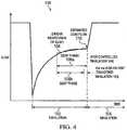
- FIGURE 4illustrates an example flow waveform 100 (i.e., flow vs. time) for an exhalation phase 102 of a breath cycle, followed by the beginning of the inspiratory phase 104 for the next breath cycle, for graphically illustrating the technique for calculating the estimated leak flow according to the technique proved herein.
- the techniqueincludes identifying the end of exhalation phase 102 (i.e., the beginning of inhalation phase 104), analyzing the flow waveform during exhalation phase 102 to determine an "end exhalation steady phase" ("EESP phase") 106, performing a linear regression (indicated by line 108) on the determined EESP phase 106 to calculate an estimated end-of-exhalation leak flow 110.
- the leak flow 110may then be used to calculate a leak factor, which may then be used by controller 50 for compensating for the leak and/or for other functions of ventilator 20.
- EESP phase 106depends on whether the next breath (which includes inhalation phase 104) is a controlled breath or a patient-triggered breath.
- EESP phase 106arefers to an EESP phase when the next breath is a controlled breath
- EESP phase 106brefers to an EESP phase when the next breath is a patient-triggered breath.
- the techniqueoperates according to a set of rules, executed by controller 50, for determining the beginning and the end of EESP phase 106a/106b.
- the rulesspecify:
- the average flow rate of the 100 ms period that ends at the end of exhalation phase 102(defined as P final ) is determined and defined as AFR Pfinal .
- the average flow rate of each successive 100 ms period (P final-1 , P final - 2 , ... P final-5 ) going backwards from P final(defined as AFR Pfinal-1 , AFR Pfinal - 2 , ... AFR Pfinal-5 ) is determined and compared to AFR Pfinal , until a 100 ms period (P final-1 , P final-2 , ... P final - 5 ) is identified for which the average flow rate (AFR Pfinal-1 , AFR Pfinal-2 , ...
- AFR Pfinal-5varies from AFR Pfinal by more than 5%.
- the duration of EESP phase 106is defined as P final plus each previous 100 ms period (P final-1 , P final-2 , ... P final-5 ) that meets the " ⁇ 5% variance test” (i.e., qualifying periods), but not the time period that failed the " ⁇ 5% variance test” (i.e., the non-qualifying period) and any previous time periods. If the average flow rate of the 100 ms period immediately preceding P final (i.e., P final-1 ) fails the " ⁇ 5% variance test", then EESP phase 106 is defined as P final .
- the duration of EESP phase 106 as determined by the " ⁇ 5% variance test”is subject to the limitations of Rules 4 and 5.
- the EESP phase 106 durationis instead capped by the limits of Rule 4 and/or 5.
- the limits of Rules 4 and 5may be applied during or after the " ⁇ 5% variance test” process described above.
- the process of Rule 6may be completed and the resulting EESP phase 106 duration is limited by Rule 4 and/or 5, if applicable.
- the process of Rule 6terminates before testing any 100 ms period (P final-1 , P final-2 , ... P final-5 ) that would, if found to be a qualifying period, exceed the limits of Rule 4 and/or 5.
- controller 50may perform a linear regression interpolation of flow waveform 100 over the determined EESP phase 106a/106b, and determine Qleak as the leak flow at the end of exhalation phase 102 according to the linear regression interpolation. Controller 50 may use any known techniques for performing the linear regression analysis.
- controller 50may calculate the leak factor K using Equation (1) above. Controller 50 may then use the calculated leak factor K for compensating for the leak and/or for other functionality.
- Qleak'can also be used for determining the inspiration phase ending (e.g., using an Esens function based on a peak flow % threshold) that is corrupted by any leak occurring if no leak compensation is implemented.
- Qleakmay be used to display a leak value on display 59 for the user to track the leak variations of the interface.
- Qleakis used in pressure controlled/support breath.
- Qleakmay be used for driving directly an inspiratory flow in a volume controlled breath.
- any or all of Qleak, PEEP, and leak factor Kmay be recalculated/determined after each breath, at regular intervals (e.g., after every x breaths or after every y seconds), upon a predetermined triggering event (e.g., a patient-triggered breath, or a change in Qleak or PEEP greater than a preset threshold value), or according to any other frequency or timing.
- a predetermined triggering evente.g., a patient-triggered breath, or a change in Qleak or PEEP greater than a preset threshold value
- any or all of Qleak, PEEP, and leak factor Kmay be utilized by controller 50 as individual calculated values, as average values of multiple iterations (e.g., a rolling average of the last five calculated Qleak values or K values), or according to any other suitable algorithm.
- Any or all of the Rules, calculations, estimations, and other functions set forth hereinmay be implemented in any suitable hardware, software, firmware, or any combination thereof.
- the Rules and equations set forth abovemay be embodied in firmware or software stored in memory or other computer readable medium associated with or accessible by controller 50.
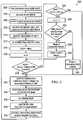
- FIGURE 5illustrates an example method 200 for determining a leak factor, and regulating one or more functions of ventilator 20 based on the determined leak factor. More specifically, method 200 incorporates the Rules and techniques discussed above.
- ventilator 20provides breathing assistance to patient 24, e.g., as controlled by controller 50 based on the current ventilation mode and/or settings.
- controller 50records a flow vs. time waveform, e.g., which may be similar to the waveform shown in FIGURE 1B .
- controller 50identifies the exhalation phase for the next breath cycle.
- controller 50identifies the beginning, end, and duration of the identified exhalation phase. Controller 50 may use any suitable techniques or rules for determining the beginning and end of the exhalation phase, e.g., example Rules 1 and 2A/2B presented above.
- controller 50analyzes the exhalation phase flow waveform to determine the "end exhalation steady phase” (EESP phase) for the exhalation phase.
- EESP phaseend exhalation steady phase
- controller 50identifies the end of the EESP phase. Controller 50 may use any suitable techniques or rules, e.g., example Rules 3A/3B presented above.
- controller 50identifies the 100 ms period that ends at the end of the exhalation phase (P final ) and determines the average flow rate during P final (AFR Pfinal .
- controller 50includes P final in the EESP phase being determined.
- controller 50resets a counter "n" equal to 0.
- controller 50determines whether the EESP phase duration plus 100 ms is greater than one-half of the duration of the identified exhalation phase determined at step 208 (see Rule 5 above). If so, the EESP phase determination is complete, and the method skips to step 232. If not, the method proceeds to step 220.
- controller 50determines whether the EESP phase duration plus 100 ms is greater than 600 ms (see Rule 4 above). If so, the EESP phase determination is complete, and the method skips to step 232. If not, the method proceeds to step 222.
- controller 50increases the counter "n” to "n + 1".
- controller 50applies the " ⁇ 5% variance test" to the period P final-n . Specifically, controller 50 determines whether the average flow rate during the period P final-n (AFR Pfinal ) varies from the average flow rate during the period P final (AFR Pfinal ) by more than 5%. If so, P final-n is identified as a Non-Qualified Period at step 226 and is not included from the EESP phase, the EESP phase determination is complete, and the method skips to step 232.
- P final-nis identified as a Qualified Period at step 228 and included in the EESP at step 230.
- the methodthen returns to step 218 to analyze the next previous 100 ms period. Steps 218-230 are repeated until a threshold is exceeded at steps 218 or 220 or until a Non-Qualified Period is identified at step 226, any of which occurrences completes the EESP determination at step 232.
- the final determined EESP for the exhalation phase being analyzedincludes the final period P final and each Qualified Period determined at step 228, if any.
- controller 50performs a linear regression of flow waveform 100 over the determined EESP phase, and determines leak flow, Qleak, at the end of exhalation phase 102, e.g., as shown in FIGURE 4 .
- Controller 50may use any known techniques for performing the linear regression analysis.
- controller 50calculates PEEP using any suitable technique, e.g., by averaging pressure over the EESP.
- controller 50calculates a leak factor K using Equation (1) above, based on the Qleak and PEEP values determined at steps 234 and 236.
- controller 50may then use the calculated leak factor K for controlling any one or more functions of ventilator 20, according to any predetermined rules or algorithms.
- the methodthen returns to step 202 for continued ventilation assistance and analysis of the next exhalation phase.
- the techniques discussed hereinmay provide one or more various advantages. For example, using the linear regression techniques discussed herein, variation associated with raw measurements regarding leak determination may be reduced. The techniques introduce a level of filtering but without the type/level of error associated with other filtering methods, such as averaging. As another example, the techniques discussed herein may be more robust to patient triggering than known techniques, in which patient triggering often negatively affects the accuracy of the leak determination.
Landscapes
- Health & Medical Sciences (AREA)
- Pulmonology (AREA)
- Heart & Thoracic Surgery (AREA)
- Engineering & Computer Science (AREA)
- Anesthesiology (AREA)
- Biomedical Technology (AREA)
- Emergency Medicine (AREA)
- Hematology (AREA)
- Life Sciences & Earth Sciences (AREA)
- Animal Behavior & Ethology (AREA)
- General Health & Medical Sciences (AREA)
- Public Health (AREA)
- Veterinary Medicine (AREA)
- Otolaryngology (AREA)
- Measurement Of The Respiration, Hearing Ability, Form, And Blood Characteristics Of Living Organisms (AREA)
Description
- The present disclosure relates generally to the field of breathing assistance systems, e.g., systems for estimating leak flow in a breathing assistance system (e.g., a ventilator).
- The present description pertains to breathing assistance devices, such as ventilators, for example. Modern ventilators commonly employ positive pressure to assist patient ventilation. For example, after determining a patient-initiated or timed trigger, the ventilator delivers a specified gas mixture into an inhalation airway connected to the patient to track a specified desired pressure or flow trajectory, causing or assisting the patient's lungs to fill. Upon reaching the end of the inspiration, the added support is removed and the patient is allowed to passively exhale and the ventilator controls the gas flow through the system to maintain a designated airway pressure level (PEEP) during the exhalation phase. Other types of ventilators are non-triggered, and mandate a specified breathing pattern regardless of patient effort.
- Modern ventilators typically include microprocessors or other controllers that employ various control schemes. These control schemes are used to command a pneumatic system (e.g., valves) that regulates the flow rates of breathing gases to and/or from the patient. Closed-loop control is often employed, using data from pressure, flow, and/or other types of sensors.
- Certain ventilation configurations provide the potential for leaks occurring at various locations in the ventilation system, e.g., at connection interfaces between system components or at the interface between a breathing mask or tube and the patient's mouth or face. The magnitude of leaks in the system can vary from setting to setting, and/or dynamically within a particular setting, dependent upon a host of variables. Leaks can impair triggering (transition into inhalation phase) and cycling (transition into exhalation phase) of the ventilator, and thus cause problems with patient-device synchrony, undesirably increase patient breathing work, degrade advisory information available to treatment providers, and/or otherwise compromise the desired respiratory therapy.
FIGURES 1A and 1B provide an example pressure waveform and corresponding flow waveform to illustrate one effect of system leaks.FIGURES 3A illustrates an example desired pressure waveform in a "Pressure Support" ventilation mode.FIGURE 3B illustrates two different flow waveforms that provide the desired pressure waveform: one waveform in a configuration with no leaks, and one waveform in a configuration with leaks. As shown, during inspiration more flow is required in the leak configuration to achieve the same pressure level as compared to no-leak configuration. Further, during exhalation, a portion of the volume exhaled by the patient may exit through the leak and be missed by the ventilator exhalation flow measurement subsystem. In many cases, the goal of the control system is to deliver a controlled pressure or flow profile or trajectory (e.g., pressure or flow as a function of time) during the inspiratory phase of the breathing cycle. In other words, control is performed to achieve a desired time-varying pressure or flow output from a pneumatic system, with an eye toward causing or aiding the desired tidal breathing (e.g., the desired pressure profile shown inFIGURE 3A ).- Improper leak accounting can compromise the timing and magnitude of the control signals applied to the pneumatic system, especially during volume delivery. Also, inaccurate (or inadequate) leak compensation can jeopardize spirometry and patient data monitoring and reporting calculations. For example, the pressure applied from the pneumatic system to the patient may cause leakage of breathing gas to atmosphere. This leakage to atmosphere may occur, for example, at some point on the inspiratory limb or expiratory limb of the patient circuit, or at the connection between the breathing circuit and pneumatic system or between the breathing circuit and the patient interface (e.g., facial mask or endotracheal tube).
- In the case of non-invasive ventilation, it is typical for some amount of breathing gas to escape via the opening defined between the patient interface (e.g., facial mask) and the surface of the patient's face. In facial masks, this opening can occur at a variety of locations around the edge of the mask, and the size and deformability of the mask can create significant leak variations. Due to the elastic nature of these masks and the movement of the patient, a leak compensation strategy assuming a constant size leak orifice (and thus constant leak flow) may be inadequate.
- Accurately estimating and/or accounting for the magnitude of the leak flow may provide significant advantages. In order for a controller to command the pneumatic system to deliver the desired amount of volume/pressure to the patient at the desired time and measure/estimate the accurate amount of gas volume exhaled by the patient, the controller needs knowledge of the extent of the leak flow over time. The fact that the leak magnitude changes dynamically during operation of the ventilator introduces additional complexity to the problem of leak modeling.
- Triggering and cycling (patient-ventilator) synchrony may also be compromised by sub-optimal leak estimation. In devices with patient-triggered and patient-cycled modalities that support spontaneous breathing efforts by the patient, it can be important to accurately detect when the patient wishes to inhale and exhale. Detection commonly occurs by using accurate pressure and/or lung flow (flow rates into or out of the patient's lung) variations. Leaks in the airway may cause an error in the signals to the sensors of the pneumatic system. This error may impede the ability of ventilator to detect the start of an inspiratory effort, which in turn compromises the ability of the controller to drive the pneumatic system in a fashion that is synchronous with the patient's spontaneous breathing cycles.
- Accordingly, attempts have been made in existing control systems compensate for ventilation system leaks, which first involves estimation of the leak. However, prior techniques for determining leaks have had limited success, particularly in the case of patient-triggered breathing (i.e., patient-triggered inspiration).
WO 2009/123981 describes systems and methods for compensating for leakage when during delivery of gas from a medical ventilator in a proportional assist mode to a patient.EP 1270036 describes a method of detecting changes in the respiratory state of a patient between inspiration and expiration.US 2007/144522 describes a method, system and device for the determination of leaks in a respirator.- Aspects of the invention are in accordance with the appended independent claims.
- As none of the claims relate to methods none of the following methods fall under the scope of the invention.
- In some examples, a method for estimating a leak flow in a breathing assistance system including a ventilation device connected to a patient is provided. The method may include accessing data of a flow waveform indicating the flow of gas between the ventilation device and the patient, identifying a specific portion of the flow waveform, and performing a linear regression of the identified portion of the flow waveform to determine an estimated leak flow in the breathing assistance system.
- In some examples, a method for controlling breathing assistance provided to a patient includes providing breathing assistance to a patient according to one or more operational parameters, estimating a leak flow, and controlling at least one of the operational parameters based at least on the estimated leak flow. Estimating the leak flow includes accessing data of a flow waveform indicating the flow of gas between the ventilation device and the patient, identifying a specific portion of the flow waveform, and performing a linear regression of the identified portion of the flow waveform to determine an estimated leak flow in the breathing assistance system.
- In some embodiments, a breathing assistance system for providing breathing assistance to a patient includes a pneumatic system for providing breathing assistance to a patient, and a controller configured to control one or more operational parameters of the pneumatic system. The controller is configured to estimate a leak flow in a breathing assistance system including a ventilation device connected to a patient by: accessing data of a flow waveform indicating the flow of gas between the ventilation device and the patient, identifying a specific portion of the flow waveform, and performing a linear regression of the identified portion of the flow waveform to determine an estimated leak flow in the breathing assistance system.
- In some embodiments, a controller for a breathing assistance system includes logic instructions embodied in tangible computer readable media and executable by one or more processors. The logic instructions are executable to access data of a flow waveform indicating the flow of gas between the ventilation device and the patient, identify a specific portion of the flow waveform, and perform a linear regression of the identified portion of the flow wavefonn to determine an estimated leak flow in the breathing assistance system.
FIGURES 1A and 1B show example pressure and flow waveforms, respectively, to illustrate certain effects commonly caused by leaks in a breathing assistance system, such as a ventilator.FIGURE 2 illustrates an example ventilation system including a controller for estimating system leaks, according to certain embodiments.FIGURE 3 illustrates an example control system and method that may be employed in the ventilation system ofFIGURE 2 , according to certain embodiments.FIGURE 4 illustrates an example flow waveform along with graphics illustrating certain techniques for estimating system leaks, according to certain embodiments.FIGURE 5 illustrates an example method of estimating a leak flow in a ventilation system (e.g., the ventilation system ofFIGURE 2 ), according to certain embodiments.- As described below, a ventilation system may be provided with control schemes that provide improved leak estimation and/or compensation. In general, these control schemes estimate the system leak based on a linear regression of flow during an end portion of the exhalation phase (referred to herein as the "end exhalation steady phase"). The present discussion focuses on specific example embodiments, though it should be appreciated that the present systems and methods are applicable to a wide variety of ventilator and other breathing assistance systems.
FIGURE 2 illustrates an examplebreathing assistance system 10 according to certain embodiments of the present disclosure.Breathing assistance system 10 includes aventilator 20 connected to apatient 24 by anairway 26.Ventilator 20 includes apneumatic system 22, acontroller 50, and adisplay 59.Pneumatic system 22 circulates breathing gases to and/or frompatient 24 viaairway 26, which couplespatient 24 topneumatic system 22 viaphysical patient interface 28 andbreathing circuit 30. Breathingcircuit 30 may include any conduits for communicating gas to and/or frompatient 24, e.g., a two-limb or one-limb circuit for carrying gas to and/or frompatient 24. A wyc fitting 36 may be provided as shown tocouplc patient 24 interface to breathingcircuit 30.- As used herein, the term "gas" may refer to any one or more gases and/or vaporized substances suitable to be delivered to and/or from a patient via one or more breathing orifices (e.g., the nose and/or mouth), such as air, nitrogen, oxygen, any other component of air, CO2, vaporized water, vaporized medicines, and/or any combination of two or more of the above, for example. As used herein, the term "patient" may refer to any person or animal that may receive breathing assistance from
system 10, regardless of the medical status, official patient status, physical location, or any other characteristic of the person. Thus, for example, patients may include persons under official medical care (e.g., hospital patients), persons not under official medical care, persons receiving care at a medical care facility, persons receiving home care, etc. - The present systems and methods have proved particularly advantageous in non-invasive settings, such as with facial breathing masks, as those settings typically are more susceptible to leaks. However, leaks do occur in a variety of settings, and the present description contemplates that
patient interface 28 may be invasive or non-invasive, and of any configuration suitable for communicating a flow of breathing gas frompatient circuit 30 to an airway ofpatient 24. Examples of suchpatient interfaces 28 include nasal masks, nasal/oral masks (e.g., as shown inFIGURE 2 ), full-face masks, nasal prongs, tracheal tubes, endotracheal tubes, nasal pillows, etc. Pneumatic system 22 may be configured in a variety of ways. In the illustrated example,system 22 includes anexpiratory module 40 coupled with anexpiratory limb 34 and aninspiratory module 42 coupled with aninspiratory limb 32. A gas flow source 44 (e.g., a compressor, one or more tanks of compressed gas, a wall outlet through which pressurized air may be supplied (e.g., in a hospital or clinic), etc.) is coupled withinspiratory module 42 to provide a gas source for ventilatory support viainspiratory limb 32.Pneumatic system 22 also includes one ormore sensors 46 for measuring various parameters such as pressure, flow, temperature, etc. Althoughsensors 46 are illustrated as being located withinpneumatic system 22,sensors 46 may be located at any suitable location or locations inbreathing assistance system 10, e.g., within a housing ofpneumatic system 22, along breathingcircuit 30, coupled topatient interface 28, etc.Pneumatic system 22 may also include a variety of other components, e.g., sources for pressurized air and/or oxygen, mixing modules, valves, tubing, accumulators, filters, etc.Controller 50 is operatively coupled topneumatic system 22 and anoperator interface 52 enabling an operator (e.g., a physician) to interact with ventilator 20 (e.g., to change ventilator settings, select operational modes, view monitored parameters, etc.).Controller 50 may include memory 54 (e.g., RAM or any other suitable volatile and/or non-volatile memories), one ormore processors 56,data storage 58, and/or other components of the type commonly found in command and control computing devices. As described in more detail below,controller 50 issues commands topneumatic system 22 in order to control the breathing assistance provided topatient 24 byventilator 20. The specific commands may be based on inputs received frompatient 24, pneumatic system 22 (e.g., pressure and/or flow sensors 46),operator interface 52, and/or other components ofbreathing assistance system 10. In the illustrated example,operator interface 52 includes adisplay device 59. In some embodiments,display device 59 includes a touch-sensitive interface or other input devices, enablingdisplay device 59 to serve both as an input and output device.FIGURE 3 illustrates an example control system and method that may be employed inventilation system 10 ofFIGURE 2 , according to certain embodiments. As shown,controller 50 issues control commands 60 to drivepneumatic system 22 and thereby circulate breathing gas to and/or frompatient 24. The illustrated interaction betweenpneumatic system 22 andpatient 24 may be viewed in terms of pressure and/or flow "signals." For example, signal 62 may be an increased pressure which is applied topatient 24 viainspiratory limb 32. Control commands 60 are based upon inputs received atcontroller 50 which may include, among other things, inputs fromoperator interface 52, and feedback from pneumatic system 22 (e.g., from pressure and/or flow sensors 46) and/or sensed frompatient 24.- In many cases, it may be desirable to establish a baseline pressure and/or flow trajectory for a given respiratory therapy session. The volume of breathing gas delivered to the patient's lungs and the volume of the gas exhaled by the patient are measured or determined, and the system leak is estimated are accounted for to ensure accurate ventilation support and data reporting and monitoring. Accordingly, the more accurate the leak estimation, the better the baseline calculation of delivered and exhaled gas volume, as well as event detection (e.g., triggering and phase transitions).
- In some embodiments,
controller 50 may calculate a "leak factor" K that may be used bycontroller 50 for compensating for system leaks and/or for other functionality. The leak factor K may be estimated by Equation (1):
- Qleak = estimated flow at the end of exhalation obtained by linear regression interpolation over an "end exhalation steady phase" ("EESP phase"), and
- PEEP = Patient pressure over the exhalation steady phase. PEEP may be determined using any known techniques. For example, PEEP for each breath may be calculated by an averaging of patient pressure measurements over the EESP phase for that breath. Alternatively, PEEP could be estimated using a linear regression technique similar to the techniques disclosed herein for estimating leak flow (Qlcak).
- Thus, the estimation of leak flow (Qleak) may be achieved by a technique including a linear regression of measured exhalation flow during a determined end portion of the exhalation phase, referred to herein as the "end exhalation steady phase" (or "EESP phase"). In general, the leak flow estimation technique includes identifying the end of the exhalation phase of a breath cycle (i.e., the beginning of the subsequent inhalation phase), analyzing the exhalation flow waveform during the exhalation phase to determine an "end exhalation steady phase" ("EESP phase"), performing a linear regression on the determined EESP phase to calculate an estimated end-of-exhalation leak flow at exhalation pressure, calculating a leak factor based on the estimated leak flow, and using the calculated leak factor to compensate for the leak and/or for other functionality. The leak flow estimation technique is discussed in greater detail below, with reference to
FIGURE 4 . FIGURE 4 illustrates an example flow waveform 100 (i.e., flow vs. time) for anexhalation phase 102 of a breath cycle, followed by the beginning of theinspiratory phase 104 for the next breath cycle, for graphically illustrating the technique for calculating the estimated leak flow according to the technique proved herein. As discussed above, the technique includes identifying the end of exhalation phase 102 (i.e., the beginning of inhalation phase 104), analyzing the flow waveform duringexhalation phase 102 to determine an "end exhalation steady phase" ("EESP phase") 106, performing a linear regression (indicated by line 108) on the determined EESP phase 106 to calculate an estimated end-of-exhalation leak flow 110. Theleak flow 110 may then be used to calculate a leak factor, which may then be used bycontroller 50 for compensating for the leak and/or for other functions ofventilator 20.- In some embodiments, the beginning and/or end of EESP phase 106 depends on whether the next breath (which includes inhalation phase 104) is a controlled breath or a patient-triggered breath. Thus, as shown in
FIGURE 4 ,EESP phase 106a refers to an EESP phase when the next breath is a controlled breath, andEESP phase 106b refers to an EESP phase when the next breath is a patient-triggered breath. - The technique operates according to a set of rules, executed by
controller 50, for determining the beginning and the end ofEESP phase 106a/106b. In certain embodiments, the rules specify: - 1. The beginning of
exhalation phase 102 is determined in any suitable manner, e.g., by the I/E ratio and R-Rate (implying a fixed inspiratory time) in a PRESS A/C mode or based on the "E sens" setting in PSV mode. - 2A. The end of
exhalation phase 102 is defined by the breath rate ("R-Rate") set in controller 50 (e.g., automatically set based on the current ventilation mode, or manually set by the physician). - 3A. The end of EESP phase 106 is defined as the end of
exhalation phase 102 - 4. The duration of EESP phase 106 is some multiple of 100 ms and cannot exceed 600 ms. Thus, EESP phase 106 is either 100, 200, 300, 400, 500, or 600 ms.
- 5. The duration of EESP phase 106 cannot exceed "exhalation duration / 2". "Exhalation duration" is defined as the duration from the beginning of exhalation phase 102 (Rule 1) to the end of exhalation phase 102 (Rule 2A).
- 6. Subject to the limitations set forth in
Rules 4 and 5, the duration of EESP phase 106 is determined by applying a "≤ 5% variance test" to successive 100 ms periods going backwards in time from the end of exhalation phase 102 (determined by Rule 2) to identify a string of zero, one, or more 100 ms periods that qualify as EESP phase 106. A particular 100 ms period qualifies for EESP phase 106 if the average flow rate varies by ≤ 5% from the average flow rate of the final 100 ms period ofexhalation phase 102. - More specifically, the average flow rate of the 100 ms period that ends at the end of exhalation phase 102 (defined as Pfinal) is determined and defined as AFRPfinal. The average flow rate of each successive 100 ms period (Pfinal-1, Pfinal-2, ... Pfinal-5) going backwards from Pfinal (defined as AFRPfinal-1, AFRPfinal-2, ... AFRPfinal-5) is determined and compared to AFRPfinal, until a 100 ms period (Pfinal-1, Pfinal-2, ... Pfinal-5) is identified for which the average flow rate (AFRPfinal-1, AFRPfinal-2, ... AFRPfinal-5) varies from AFRPfinal by more than 5%. The duration of EESP phase 106 is defined as Pfinal plus each previous 100 ms period (Pfinal-1, Pfinal-2, ... Pfinal-5) that meets the "≤ 5% variance test" (i.e., qualifying periods), but not the time period that failed the "≤ 5% variance test" (i.e., the non-qualifying period) and any previous time periods. If the average flow rate of the 100 ms period immediately preceding Pfinal (i.e., Pfinal-1) fails the "≤ 5% variance test", then EESP phase 106 is defined as Pfinal.
- As mentioned at the beginning of Rule 6, the duration of EESP phase 106 as determined by the "≤ 5% variance test" is subject to the limitations of
Rules 4 and 5. Thus, where the "≤ 5% variance test" process described above would result in a EESP phase 106 duration that would exceed the limits prescribed by Rule 4 and/or 5, the EESP phase 106 duration is instead capped by the limits of Rule 4 and/or 5. The limits ofRules 4 and 5 may be applied during or after the "≤ 5% variance test" process described above. For example, in some embodiments, the process of Rule 6 may be completed and the resulting EESP phase 106 duration is limited by Rule 4 and/or 5, if applicable. In other embodiments, the process of Rule 6 terminates before testing any 100 ms period (Pfinal-1, Pfinal-2, ... Pfinal-5) that would, if found to be a qualifying period, exceed the limits of Rule 4 and/or 5. - 1. Same as
Rule 1 above for the scenario of a subsequent controlled breath. - 2B. The end of
exhalation phase 102 is defined by the detection of an inspiratory trigger. - 3B. The end of EESP phase 106 is defined as predetermined duration, 100 ms, before the end of
exhalation phase 102. - 4. Same as Rule 4 above for the scenario of a subsequent controlled breath.
- 5. Same as
Rule 5 above for the scenario of a subsequent controlled breath, - 6. Same as Rule 6 above for the scenario of a subsequent controlled breath. In the example Rules presented above, only Rules 2 and 3 differ depending on whether the next breath is a patient-triggered breath. Thus, only Rules 2 and 3 are distinguished by 2A/2B and 3A/3B notations.
- It should be understood that the various values set forth in the preceding Rules are examples only, and any other suitable values may be used. For example, the following values are examples only and any other suitable values may be used:
- the 600 ms limit for EESP phase 106 set forth in Rule 4,
- the number of possible EESP phase 106 durations (6) set forth in Rule 4,
- the "exhalation duration /2" formula set forth in
Rule 5, - the 100 ms period duration set forth in Rules 3A/3B and 6, and
- the 5% variance threshold set forth in Rule 6.
- It should also be understood that depending on the particular embodiment, one, some, or all of the Rules set forth herein may be used. Further, any one or more additional Rules may be used in conjunction with any or all of the Rules set forth above.
- After determining the beginning and the end (and thus the duration) of
EESP phase 106a/106b,controller 50 may perform a linear regression interpolation offlow waveform 100 over thedetermined EESP phase 106a/106b, and determine Qleak as the leak flow at the end ofexhalation phase 102 according to the linear regression interpolation.Controller 50 may use any known techniques for performing the linear regression analysis. - After determining the end of exhalation flow, Qleak,
controller 50 may calculate the leak factor K using Equation (1) above.Controller 50 may then use the calculated leak factor K for compensating for the leak and/or for other functionality. The leak factor K may be used for various purposes. For example,controller 50 may use the leak factor K for evaluating the real patient flow (e.g., by subtracting the inspiration leak flow Qleak' = (K∗ Pressure)0,5 = Qleak∗ (Pressure / PEEP)0-5 at the current pressure from the flow measured by flow sensor 46). Thencontroller 50 may calculate the tidal volume by integrating Qleak' over the inspiratory phase. As another example, Qleak' can also be used for determining the inspiration phase ending (e.g., using an Esens function based on a peak flow % threshold) that is corrupted by any leak occurring if no leak compensation is implemented. As another example, Qleak may be used to display a leak value ondisplay 59 for the user to track the leak variations of the interface. In some embodiments, Qleak is used in pressure controlled/support breath. However, in other embodiments, Qleak may be used for driving directly an inspiratory flow in a volume controlled breath. - Any or all of Qleak, PEEP, and leak factor K may be recalculated/determined after each breath, at regular intervals (e.g., after every x breaths or after every y seconds), upon a predetermined triggering event (e.g., a patient-triggered breath, or a change in Qleak or PEEP greater than a preset threshold value), or according to any other frequency or timing. In addition, any or all of Qleak, PEEP, and leak factor K may be utilized by
controller 50 as individual calculated values, as average values of multiple iterations (e.g., a rolling average of the last five calculated Qleak values or K values), or according to any other suitable algorithm. - Any or all of the Rules, calculations, estimations, and other functions set forth herein may be implemented in any suitable hardware, software, firmware, or any combination thereof. For example, the Rules and equations set forth above may be embodied in firmware or software stored in memory or other computer readable medium associated with or accessible by
controller 50. FIGURE 5 illustrates anexample method 200 for determining a leak factor, and regulating one or more functions ofventilator 20 based on the determined leak factor. More specifically,method 200 incorporates the Rules and techniques discussed above.- At
step 202,ventilator 20 provides breathing assistance topatient 24, e.g., as controlled bycontroller 50 based on the current ventilation mode and/or settings. - At
step 204,controller 50 records a flow vs. time waveform, e.g., which may be similar to the waveform shown inFIGURE 1B . - At
step 206,controller 50 identifies the exhalation phase for the next breath cycle. - At
step 208,controller 50 identifies the beginning, end, and duration of the identified exhalation phase.Controller 50 may use any suitable techniques or rules for determining the beginning and end of the exhalation phase, e.g.,example Rules 1 and 2A/2B presented above. - At steps 210-232,
controller 50 analyzes the exhalation phase flow waveform to determine the "end exhalation steady phase" (EESP phase) for the exhalation phase. - At
step 210,controller 50 identifies the end of the EESP phase.Controller 50 may use any suitable techniques or rules, e.g., example Rules 3A/3B presented above. - At
step 212,controller 50 identifies the 100 ms period that ends at the end of the exhalation phase (Pfinal) and determines the average flow rate during Pfinal (AFRPfinal. - At
step 214,controller 50 includes Pfinal in the EESP phase being determined. - At
step 216,controller 50 resets a counter "n" equal to 0. - At
step 218,controller 50 determines whether the EESP phase duration plus 100 ms is greater than one-half of the duration of the identified exhalation phase determined at step 208 (seeRule 5 above). If so, the EESP phase determination is complete, and the method skips to step 232. If not, the method proceeds to step 220. - At
step 220,controller 50 determines whether the EESP phase duration plus 100 ms is greater than 600 ms (see Rule 4 above). If so, the EESP phase determination is complete, and the method skips to step 232. If not, the method proceeds to step 222. - At
step 222,controller 50 increases the counter "n" to "n + 1". - At
step 224,controller 50 applies the "≤ 5% variance test" to the period Pfinal-n. Specifically,controller 50 determines whether the average flow rate during the period Pfinal-n (AFRPfinal) varies from the average flow rate during the period Pfinal (AFRPfinal) by more than 5%. If so, Pfinal-n is identified as a Non-Qualified Period atstep 226 and is not included from the EESP phase, the EESP phase determination is complete, and the method skips to step 232. - Alternatively, if AFRPfinal varies from AFRPfinal by less than or equal to 5%, Pfinal-n is identified as a Qualified Period at
step 228 and included in the EESP atstep 230. The method then returns to step 218 to analyze the next previous 100 ms period. Steps 218-230 are repeated until a threshold is exceeded atsteps step 226, any of which occurrences completes the EESP determination atstep 232. - As indicated as
step 232, the final determined EESP for the exhalation phase being analyzed includes the final period Pfinal and each Qualified Period determined atstep 228, if any. - At
step 234,controller 50 performs a linear regression offlow waveform 100 over the determined EESP phase, and determines leak flow, Qleak, at the end ofexhalation phase 102, e.g., as shown inFIGURE 4 .Controller 50 may use any known techniques for performing the linear regression analysis. - At
step 236,controller 50 calculates PEEP using any suitable technique, e.g., by averaging pressure over the EESP. - At
step 238,controller 50 calculates a leak factor K using Equation (1) above, based on the Qleak and PEEP values determined atsteps - At
step 240,controller 50 may then use the calculated leak factor K for controlling any one or more functions ofventilator 20, according to any predetermined rules or algorithms. - The method then returns to step 202 for continued ventilation assistance and analysis of the next exhalation phase.
- The techniques discussed herein may provide one or more various advantages. For example, using the linear regression techniques discussed herein, variation associated with raw measurements regarding leak determination may be reduced. The techniques introduce a level of filtering but without the type/level of error associated with other filtering methods, such as averaging. As another example, the techniques discussed herein may be more robust to patient triggering than known techniques, in which patient triggering often negatively affects the accuracy of the leak determination.
- It will be appreciated that while the disclosure is particularly described in the context of breathing assistance systems, the apparatuses, techniques, and methods disclosed herein may be similarly applied in other contexts. For example, similar principles may be applied in certain CPAP devices, BiPAP devices, or other suitable types of breathing assistance devices. Additionally, it should be understood that various changes, substitutions and alterations can be made herein without departing from the scope of the invention as defined by the following claims.

Claims (6)
- A controller for a breathing assistance system, wherein the controller is configured to estimate a leak flow by:accessing data of a flow waveform (100) indicating a flow of gas between the ventilation device (20) and the patient;identifying a steady phase portion of the flow waveform (100), wherein identifying the steady phase portion of the flow waveform (100) comprises:determining a first representative flow rate for a first period of the flow waveform (100);determining a second representative flow rate for at least a second period of the flow waveform (100), anddefining a duration of the steady phase portion of the flow waveform (100) to include the first period and the second period when the second representative flow rate varies from the first representative flow rate by less than a predetermined amount; andperforming a linear regression on the identified steady phase portion of the flow waveform (100) to determine an estimated leak flow.
- The controller according to claim 1 further configured to control at least one of the one or more operational parameters.
- The controller according to claim 1 further configured to:determine at least one further representative flow rate for at least one additional period of the flow waveform (100); anddefine the duration of the steady phase portion to include the at least one additional period when the at least one further flow rate varies from the first representative flow rate by less than the predetermined amount.
- The controller according to claim 1, wherein the first period and the second period correspond to consecutive periods of the flow waveform (100).
- The controller according to claim 1, further comprising:
at least one processor and at least one memory storing computer readable instructions that when executed cause the controller to perform the steps of accessing, identifying and performing of claim 1. - A breathing assistance system including a ventilation device (20) for delivering respiratory gases to a patient, the breathing assistance system comprising a controller as claimed in any of claims 1 to 5.
Applications Claiming Priority (4)
| Application Number | Priority Date | Filing Date | Title |
|---|---|---|---|
| US30309310P | 2010-02-10 | 2010-02-10 | |
| US12/769,876US8707952B2 (en) | 2010-02-10 | 2010-04-29 | Leak determination in a breathing assistance system |
| PCT/US2011/023982WO2011100215A1 (en) | 2010-02-10 | 2011-02-08 | Leak determination in a breathing assistance system |
| EP11705344.7AEP2533837B1 (en) | 2010-02-10 | 2011-02-08 | Leak determination in a breathing assistance system |
Related Parent Applications (1)
| Application Number | Title | Priority Date | Filing Date |
|---|---|---|---|
| EP11705344.7ADivisionEP2533837B1 (en) | 2010-02-10 | 2011-02-08 | Leak determination in a breathing assistance system |
Publications (2)
| Publication Number | Publication Date |
|---|---|
| EP3338844A1 EP3338844A1 (en) | 2018-06-27 |
| EP3338844B1true EP3338844B1 (en) | 2020-07-15 |
Family
ID=44354258
Family Applications (2)
| Application Number | Title | Priority Date | Filing Date |
|---|---|---|---|
| EP17198666.4AActiveEP3338844B1 (en) | 2010-02-10 | 2011-02-08 | Leak determination in a breathing assistance system |
| EP11705344.7AActiveEP2533837B1 (en) | 2010-02-10 | 2011-02-08 | Leak determination in a breathing assistance system |
Family Applications After (1)
| Application Number | Title | Priority Date | Filing Date |
|---|---|---|---|
| EP11705344.7AActiveEP2533837B1 (en) | 2010-02-10 | 2011-02-08 | Leak determination in a breathing assistance system |
Country Status (4)
| Country | Link |
|---|---|
| US (5) | US8707952B2 (en) |
| EP (2) | EP3338844B1 (en) |
| CA (1) | CA2788270C (en) |
| WO (1) | WO2011100215A1 (en) |
Families Citing this family (102)
| Publication number | Priority date | Publication date | Assignee | Title |
|---|---|---|---|---|
| US5915379A (en) | 1997-03-14 | 1999-06-29 | Nellcor Puritan Bennett Incorporated | Graphic user interface for a patient ventilator |
| US8021310B2 (en) | 2006-04-21 | 2011-09-20 | Nellcor Puritan Bennett Llc | Work of breathing display for a ventilation system |
| US7784461B2 (en) | 2006-09-26 | 2010-08-31 | Nellcor Puritan Bennett Llc | Three-dimensional waveform display for a breathing assistance system |
| US10207069B2 (en) | 2008-03-31 | 2019-02-19 | Covidien Lp | System and method for determining ventilator leakage during stable periods within a breath |
| US8746248B2 (en) | 2008-03-31 | 2014-06-10 | Covidien Lp | Determination of patient circuit disconnect in leak-compensated ventilatory support |
| US8267085B2 (en) | 2009-03-20 | 2012-09-18 | Nellcor Puritan Bennett Llc | Leak-compensated proportional assist ventilation |
| US8272380B2 (en) | 2008-03-31 | 2012-09-25 | Nellcor Puritan Bennett, Llc | Leak-compensated pressure triggering in medical ventilators |
| US8792949B2 (en) | 2008-03-31 | 2014-07-29 | Covidien Lp | Reducing nuisance alarms |
| WO2009149357A1 (en) | 2008-06-06 | 2009-12-10 | Nellcor Puritan Bennett Llc | Systems and methods for ventilation in proportion to patient effort |
| US8424520B2 (en) | 2008-09-23 | 2013-04-23 | Covidien Lp | Safe standby mode for ventilator |
| US8181648B2 (en) | 2008-09-26 | 2012-05-22 | Nellcor Puritan Bennett Llc | Systems and methods for managing pressure in a breathing assistance system |
| US8393323B2 (en) | 2008-09-30 | 2013-03-12 | Covidien Lp | Supplemental gas safety system for a breathing assistance system |
| US8302602B2 (en) | 2008-09-30 | 2012-11-06 | Nellcor Puritan Bennett Llc | Breathing assistance system with multiple pressure sensors |
| US8424521B2 (en) | 2009-02-27 | 2013-04-23 | Covidien Lp | Leak-compensated respiratory mechanics estimation in medical ventilators |
| US8418691B2 (en) | 2009-03-20 | 2013-04-16 | Covidien Lp | Leak-compensated pressure regulated volume control ventilation |
| US8789529B2 (en) | 2009-08-20 | 2014-07-29 | Covidien Lp | Method for ventilation |
| US8439036B2 (en) | 2009-12-01 | 2013-05-14 | Covidien Lp | Exhalation valve assembly with integral flow sensor |
| US8421465B2 (en) | 2009-12-02 | 2013-04-16 | Covidien Lp | Method and apparatus for indicating battery cell status on a battery pack assembly used during mechanical ventilation |
| US8424523B2 (en) | 2009-12-03 | 2013-04-23 | Covidien Lp | Ventilator respiratory gas accumulator with purge valve |
| US9119925B2 (en) | 2009-12-04 | 2015-09-01 | Covidien Lp | Quick initiation of respiratory support via a ventilator user interface |
| US8924878B2 (en) | 2009-12-04 | 2014-12-30 | Covidien Lp | Display and access to settings on a ventilator graphical user interface |
| US8499252B2 (en) | 2009-12-18 | 2013-07-30 | Covidien Lp | Display of respiratory data graphs on a ventilator graphical user interface |
| US9262588B2 (en) | 2009-12-18 | 2016-02-16 | Covidien Lp | Display of respiratory data graphs on a ventilator graphical user interface |
| US8707952B2 (en) | 2010-02-10 | 2014-04-29 | Covidien Lp | Leak determination in a breathing assistance system |
| US8511306B2 (en) | 2010-04-27 | 2013-08-20 | Covidien Lp | Ventilation system with system status display for maintenance and service information |
| US8638200B2 (en) | 2010-05-07 | 2014-01-28 | Covidien Lp | Ventilator-initiated prompt regarding Auto-PEEP detection during volume ventilation of non-triggering patient |
| US8607790B2 (en) | 2010-06-30 | 2013-12-17 | Covidien Lp | Ventilator-initiated prompt regarding auto-PEEP detection during pressure ventilation of patient exhibiting obstructive component |
| US8607791B2 (en) | 2010-06-30 | 2013-12-17 | Covidien Lp | Ventilator-initiated prompt regarding auto-PEEP detection during pressure ventilation |
| US8607788B2 (en) | 2010-06-30 | 2013-12-17 | Covidien Lp | Ventilator-initiated prompt regarding auto-PEEP detection during volume ventilation of triggering patient exhibiting obstructive component |
| US8607789B2 (en) | 2010-06-30 | 2013-12-17 | Covidien Lp | Ventilator-initiated prompt regarding auto-PEEP detection during volume ventilation of non-triggering patient exhibiting obstructive component |
| US8676285B2 (en) | 2010-07-28 | 2014-03-18 | Covidien Lp | Methods for validating patient identity |
| NZ703966A (en)* | 2010-07-30 | 2016-07-29 | Resmed Ltd | Methods and devices with leak detection |
| US8554298B2 (en) | 2010-09-21 | 2013-10-08 | Cividien LP | Medical ventilator with integrated oximeter data |
| US8757153B2 (en) | 2010-11-29 | 2014-06-24 | Covidien Lp | Ventilator-initiated prompt regarding detection of double triggering during ventilation |
| US8595639B2 (en) | 2010-11-29 | 2013-11-26 | Covidien Lp | Ventilator-initiated prompt regarding detection of fluctuations in resistance |
| US8757152B2 (en) | 2010-11-29 | 2014-06-24 | Covidien Lp | Ventilator-initiated prompt regarding detection of double triggering during a volume-control breath type |
| US8788236B2 (en) | 2011-01-31 | 2014-07-22 | Covidien Lp | Systems and methods for medical device testing |
| US8676529B2 (en) | 2011-01-31 | 2014-03-18 | Covidien Lp | Systems and methods for simulation and software testing |
| US8783250B2 (en) | 2011-02-27 | 2014-07-22 | Covidien Lp | Methods and systems for transitory ventilation support |
| US9038633B2 (en) | 2011-03-02 | 2015-05-26 | Covidien Lp | Ventilator-initiated prompt regarding high delivered tidal volume |
| US8714154B2 (en) | 2011-03-30 | 2014-05-06 | Covidien Lp | Systems and methods for automatic adjustment of ventilator settings |
| US8776792B2 (en) | 2011-04-29 | 2014-07-15 | Covidien Lp | Methods and systems for volume-targeted minimum pressure-control ventilation |
| US9629971B2 (en) | 2011-04-29 | 2017-04-25 | Covidien Lp | Methods and systems for exhalation control and trajectory optimization |
| US9089657B2 (en) | 2011-10-31 | 2015-07-28 | Covidien Lp | Methods and systems for gating user initiated increases in oxygen concentration during ventilation |
| US9364624B2 (en) | 2011-12-07 | 2016-06-14 | Covidien Lp | Methods and systems for adaptive base flow |
| WO2013098686A1 (en)* | 2011-12-27 | 2013-07-04 | Koninklijke Philips Electronics N.V. | Compensation of breath delivery |
| US9498589B2 (en) | 2011-12-31 | 2016-11-22 | Covidien Lp | Methods and systems for adaptive base flow and leak compensation |
| US9022031B2 (en) | 2012-01-31 | 2015-05-05 | Covidien Lp | Using estimated carinal pressure for feedback control of carinal pressure during ventilation |
| US9327089B2 (en)* | 2012-03-30 | 2016-05-03 | Covidien Lp | Methods and systems for compensation of tubing related loss effects |
| US8844526B2 (en) | 2012-03-30 | 2014-09-30 | Covidien Lp | Methods and systems for triggering with unknown base flow |
| US9993604B2 (en) | 2012-04-27 | 2018-06-12 | Covidien Lp | Methods and systems for an optimized proportional assist ventilation |
| US9144658B2 (en) | 2012-04-30 | 2015-09-29 | Covidien Lp | Minimizing imposed expiratory resistance of mechanical ventilator by optimizing exhalation valve control |
| US10362967B2 (en) | 2012-07-09 | 2019-07-30 | Covidien Lp | Systems and methods for missed breath detection and indication |
| US9027552B2 (en) | 2012-07-31 | 2015-05-12 | Covidien Lp | Ventilator-initiated prompt or setting regarding detection of asynchrony during ventilation |
| JP6651357B2 (en) | 2012-08-20 | 2020-02-19 | コーニンクレッカ フィリップス エヌ ヴェKoninklijke Philips N.V. | Removal of patient interface assembly |
| US9375542B2 (en) | 2012-11-08 | 2016-06-28 | Covidien Lp | Systems and methods for monitoring, managing, and/or preventing fatigue during ventilation |
| US9289573B2 (en) | 2012-12-28 | 2016-03-22 | Covidien Lp | Ventilator pressure oscillation filter |
| US9492629B2 (en) | 2013-02-14 | 2016-11-15 | Covidien Lp | Methods and systems for ventilation with unknown exhalation flow and exhalation pressure |
| USD731049S1 (en) | 2013-03-05 | 2015-06-02 | Covidien Lp | EVQ housing of an exhalation module |
| USD731048S1 (en) | 2013-03-08 | 2015-06-02 | Covidien Lp | EVQ diaphragm of an exhalation module |
| USD736905S1 (en) | 2013-03-08 | 2015-08-18 | Covidien Lp | Exhalation module EVQ housing |
| USD731065S1 (en) | 2013-03-08 | 2015-06-02 | Covidien Lp | EVQ pressure sensor filter of an exhalation module |
| USD701601S1 (en) | 2013-03-08 | 2014-03-25 | Covidien Lp | Condensate vial of an exhalation module |
| USD692556S1 (en) | 2013-03-08 | 2013-10-29 | Covidien Lp | Expiratory filter body of an exhalation module |
| USD744095S1 (en) | 2013-03-08 | 2015-11-24 | Covidien Lp | Exhalation module EVQ internal flow sensor |
| USD693001S1 (en) | 2013-03-08 | 2013-11-05 | Covidien Lp | Neonate expiratory filter assembly of an exhalation module |
| US9358355B2 (en) | 2013-03-11 | 2016-06-07 | Covidien Lp | Methods and systems for managing a patient move |
| US9981096B2 (en) | 2013-03-13 | 2018-05-29 | Covidien Lp | Methods and systems for triggering with unknown inspiratory flow |
| US9950135B2 (en) | 2013-03-15 | 2018-04-24 | Covidien Lp | Maintaining an exhalation valve sensor assembly |
| US10064583B2 (en) | 2013-08-07 | 2018-09-04 | Covidien Lp | Detection of expiratory airflow limitation in ventilated patient |
| US9675771B2 (en) | 2013-10-18 | 2017-06-13 | Covidien Lp | Methods and systems for leak estimation |
| CN104740735B (en)* | 2013-12-26 | 2018-07-20 | 北京谊安医疗系统股份有限公司 | Expiration tidal volume VTE computational methods |
| DE102014000101A1 (en)* | 2014-01-10 | 2015-07-16 | Dräger Medical GmbH | Method for leakage testing of a coaxial breathing tube, leakage test system and connecting element |
| CN103977492B (en)* | 2014-05-29 | 2016-04-27 | 北京航空航天大学 | A kind of method controlling ventilation air leakage based on pressure waveform estimated capacity |
| CN103977493B (en)* | 2014-05-29 | 2016-08-17 | 北京航空航天大学 | Can be used for the experiment porch of invasive ventilation gas leakage detection |
| US9808591B2 (en) | 2014-08-15 | 2017-11-07 | Covidien Lp | Methods and systems for breath delivery synchronization |
| US11344690B2 (en) | 2014-09-16 | 2022-05-31 | Truphatek International Ltd. | Imaging device and data management system for medical device |
| EP3209357B1 (en) | 2014-10-24 | 2019-07-31 | Koninklijke Philips N.V. | System for controlling leak |
| US9950129B2 (en) | 2014-10-27 | 2018-04-24 | Covidien Lp | Ventilation triggering using change-point detection |
| EP3212263B1 (en)* | 2014-10-28 | 2025-02-26 | Fisher & Paykel Healthcare Limited | Patient specific auto-flowrate control |
| US9925346B2 (en) | 2015-01-20 | 2018-03-27 | Covidien Lp | Systems and methods for ventilation with unknown exhalation flow |
| WO2016140980A1 (en) | 2015-03-02 | 2016-09-09 | Covidien Lp | Medical ventilator, method for replacing an oxygen sensor on a medical ventilator, and medical ventilator assembly |
| EP4186548A1 (en) | 2015-04-02 | 2023-05-31 | Hill-Rom Services PTE. LTD. | Mask leakage detection for a respiratory device |
| USD775345S1 (en) | 2015-04-10 | 2016-12-27 | Covidien Lp | Ventilator console |
| EP3302666A4 (en) | 2015-05-28 | 2019-01-30 | Fisher&Paykel Healthcare Limited | GAS TREATMENT SYSTEM |
| US11027081B2 (en)* | 2015-07-07 | 2021-06-08 | Koninklijke Philips N.V. | Method and systems for patient airway and leak flow estimation for non-invasive ventilation |
| EP3334485B1 (en)* | 2015-08-14 | 2024-03-06 | ResMed Pty Ltd | Monitoring respiratory pressure therapy |
| US20170128317A1 (en)* | 2015-11-06 | 2017-05-11 | Hill-Rom Services Pte Limited | Dynamic control of respiratory therapy devices |
| US10765822B2 (en) | 2016-04-18 | 2020-09-08 | Covidien Lp | Endotracheal tube extubation detection |
| US10869977B2 (en)* | 2016-04-28 | 2020-12-22 | Invent Medical Corporation | System and method for accurate estimation of intentional and unintentional leaks in flow generation systems |
| CN109069062B (en)* | 2016-05-10 | 2022-08-02 | 皇家飞利浦有限公司 | Determining airway flow restriction values |
| CN106840523B (en)* | 2016-11-04 | 2018-05-29 | 广东技术师范学院 | The synergetic immunity detection method of leakage in a kind of tyre vulcanizer drain valve steam |
| EP3558431A1 (en)* | 2016-12-20 | 2019-10-30 | Koninklijke Philips N.V. | Determining respiratory mechanic parameters in the presence of intrinsic positive end-expiratory pressure |
| CN106730199B (en)* | 2016-12-23 | 2019-10-01 | 湖南明康中锦医疗科技发展有限公司 | The device and ventilator of continuous positive pressure ventilation pressure stabilizing |
| JP6520963B2 (en)* | 2017-01-20 | 2019-05-29 | ダイキン工業株式会社 | Oxygen concentrator |
| AU2018353928B2 (en) | 2017-11-14 | 2019-06-13 | Covidien Lp | Methods and systems for drive pressure spontaneous ventilation |
| DE102017011625A1 (en) | 2017-12-15 | 2019-07-18 | Drägerwerk AG & Co. KGaA | A method, computer program, apparatus and respiratory system for detecting a leak in a patient gas module |
| EP3834720A4 (en)* | 2018-08-21 | 2022-03-09 | Shenzhen Mindray Bio-Medical Electronics Co., Ltd | METHOD AND APPARATUS FOR RECOGNIZING AN ABNORMAL RESPIRATORY TRACT, VENTILATION DEVICE AND STORAGE MEDIA |
| CN109011066B (en)* | 2018-08-29 | 2019-07-02 | 宋兴荣 | A kind of ventilator schema control system |
| US11906097B2 (en)* | 2019-09-04 | 2024-02-20 | Vyaire Medical, Inc. | Ventilation leak component |
| IT201900020532A1 (en)* | 2019-11-07 | 2021-05-07 | Univ Degli Studi Di Palermo | Control of tidal volumes during non-invasive ventilation via helmet |
| DE102020002570A1 (en)* | 2020-04-29 | 2021-11-04 | Drägerwerk AG & Co. KGaA | Method and device for detecting a leak in a ventilation circuit |
Family Cites Families (299)
| Publication number | Priority date | Publication date | Assignee | Title |
|---|---|---|---|---|
| US5150291A (en)* | 1986-03-31 | 1992-09-22 | Puritan-Bennett Corporation | Respiratory ventilation apparatus |
| US4752089A (en)* | 1987-01-29 | 1988-06-21 | Puritan-Bennett Corporation | Connector means providing fluid-tight but relatively rotatable joint |
| US4921642A (en)* | 1987-12-03 | 1990-05-01 | Puritan-Bennett Corporation | Humidifier module for use in a gas humidification assembly |
| US5325861A (en) | 1989-04-12 | 1994-07-05 | Puritan-Bennett Corporation | Method and apparatus for measuring a parameter of a gas in isolation from gas pressure fluctuations |
| US5072737A (en) | 1989-04-12 | 1991-12-17 | Puritan-Bennett Corporation | Method and apparatus for metabolic monitoring |
| US5259373A (en) | 1989-05-19 | 1993-11-09 | Puritan-Bennett Corporation | Inspiratory airway pressure system controlled by the detection and analysis of patient airway sounds |
| US4954799A (en)* | 1989-06-02 | 1990-09-04 | Puritan-Bennett Corporation | Proportional electropneumatic solenoid-controlled valve |
| US5299568A (en)* | 1989-06-22 | 1994-04-05 | Puritan-Bennett Corporation | Method for controlling mixing and delivery of respiratory gas |
| DE3930362A1 (en) | 1989-09-12 | 1991-03-21 | Draegerwerk Ag | CIRCUIT BREATH PROTECTOR |
| US5239995A (en)* | 1989-09-22 | 1993-08-31 | Respironics, Inc. | Sleep apnea treatment apparatus |
| US5632269A (en)* | 1989-09-22 | 1997-05-27 | Respironics Inc. | Breathing gas delivery method and apparatus |
| US5148802B1 (en)* | 1989-09-22 | 1997-08-12 | Respironics Inc | Method and apparatus for maintaining airway patency to treat sleep apnea and other disorders |
| US5161525A (en) | 1990-05-11 | 1992-11-10 | Puritan-Bennett Corporation | System and method for flow triggering of pressure supported ventilation |
| US5390666A (en) | 1990-05-11 | 1995-02-21 | Puritan-Bennett Corporation | System and method for flow triggering of breath supported ventilation |
| US5237987A (en)* | 1990-06-07 | 1993-08-24 | Infrasonics, Inc. | Human lung ventilator system |
| US5407174A (en) | 1990-08-31 | 1995-04-18 | Puritan-Bennett Corporation | Proportional electropneumatic solenoid-controlled valve |
| US5057822A (en)* | 1990-09-07 | 1991-10-15 | Puritan-Bennett Corporation | Medical gas alarm system |
| JP2688453B2 (en) | 1990-09-19 | 1997-12-10 | ザ ユニバーシティ オブ メルボルン | CO2 monitoring in arterial blood and closed loop control device |
| US5279549A (en)* | 1991-01-04 | 1994-01-18 | Sherwood Medical Company | Closed ventilation and suction catheter system |
| US5542415A (en) | 1991-05-07 | 1996-08-06 | Infrasonics, Inc. | Apparatus and process for controlling the ventilation of the lungs of a patient |
| US6629527B1 (en) | 1991-10-17 | 2003-10-07 | Respironics, Inc. | Sleep apnea treatment apparatus |
| US7013892B2 (en)* | 1991-11-01 | 2006-03-21 | Ric Investments, Llc | Sleep apnea treatment apparatus |
| AU3127093A (en)* | 1991-11-14 | 1993-06-15 | Paul M. Suratt | Auto cpap system |
| US5271389A (en) | 1992-02-12 | 1993-12-21 | Puritan-Bennett Corporation | Ventilator control system that generates, measures, compares, and corrects flow rates |
| US5385142A (en) | 1992-04-17 | 1995-01-31 | Infrasonics, Inc. | Apnea-responsive ventilator system and method |
| US5333606A (en) | 1992-04-24 | 1994-08-02 | Sherwood Medical Company | Method for using a respirator accessory access port and adaptor therefore |
| US5645048A (en) | 1992-05-06 | 1997-07-08 | The Kendall Company | Patient ventilating apparatus with modular components |
| FR2692152B1 (en) | 1992-06-15 | 1997-06-27 | Pierre Medical Sa | BREATHING AID, PARTICULARLY FOR TREATING SLEEP APNEA. |
| FR2695830B1 (en)* | 1992-09-18 | 1994-12-30 | Pierre Medical Sa | Breathing aid device. |
| US5339807A (en) | 1992-09-22 | 1994-08-23 | Puritan-Bennett Corporation | Exhalation valve stabilizing apparatus |
| US5357946A (en) | 1992-10-19 | 1994-10-25 | Sherwood Medical Company | Ventilator manifold with accessory access port and adaptors therefore |
| US5517983A (en) | 1992-12-09 | 1996-05-21 | Puritan Bennett Corporation | Compliance meter for respiratory therapy |
| US5368019A (en) | 1992-12-16 | 1994-11-29 | Puritan-Bennett Corporation | System and method for operating a respirator compressor system under low voltage conditions |
| US5438980A (en) | 1993-01-12 | 1995-08-08 | Puritan-Bennett Corporation | Inhalation/exhalation respiratory phase detection circuit |
| US5443075A (en) | 1993-03-01 | 1995-08-22 | Puritan-Bennett Corporation | Flow measuring apparatus |
| US5813399A (en) | 1993-03-16 | 1998-09-29 | Puritan Bennett Corporation | System and method for closed loop airway pressure control during the inspiratory cycle of a breath in a patient ventilator using the exhalation valve as a microcomputer-controlled relief valve |
| US5351522A (en) | 1993-11-02 | 1994-10-04 | Aequitron Medical, Inc. | Gas sensor |
| US5401135A (en) | 1994-01-14 | 1995-03-28 | Crow River Industries | Foldable platform wheelchair lift with safety barrier |
| US5555880A (en)* | 1994-01-31 | 1996-09-17 | Southwest Research Institute | High frequency oscillatory ventilator and respiratory measurement system |
| US6105575A (en)* | 1994-06-03 | 2000-08-22 | Respironics, Inc. | Method and apparatus for providing positive airway pressure to a patient |
| US6932084B2 (en)* | 1994-06-03 | 2005-08-23 | Ric Investments, Inc. | Method and apparatus for providing positive airway pressure to a patient |
| US5535738A (en)* | 1994-06-03 | 1996-07-16 | Respironics, Inc. | Method and apparatus for providing proportional positive airway pressure to treat sleep disordered breathing |
| US5794615A (en)* | 1994-06-03 | 1998-08-18 | Respironics, Inc. | Method and apparatus for providing proportional positive airway pressure to treat congestive heart failure |
| US5524615A (en) | 1994-09-08 | 1996-06-11 | Puritan-Bennett Corporation | Ventilator airway fluid collection system |
| US5596984A (en) | 1994-09-12 | 1997-01-28 | Puritan-Bennett Corporation | Lung ventilator safety circuit |
| US5632270A (en) | 1994-09-12 | 1997-05-27 | Puritan-Bennett Corporation | Method and apparatus for control of lung ventilator exhalation circuit |
| US6866040B1 (en) | 1994-09-12 | 2005-03-15 | Nellcor Puritan Bennett France Developpement | Pressure-controlled breathing aid |
| US5531221A (en) | 1994-09-12 | 1996-07-02 | Puritan Bennett Corporation | Double and single acting piston ventilators |
| FR2724322A1 (en) | 1994-09-12 | 1996-03-15 | Pierre Medical Sa | PRESSURE CONTROLLED BREATHING AID |
| US5794986A (en) | 1994-09-15 | 1998-08-18 | Infrasonics, Inc. | Semi-disposable ventilator breathing circuit tubing with releasable coupling |
| US5520071A (en) | 1994-09-30 | 1996-05-28 | Crow River Industries, Incorporated | Steering wheel control attachment apparatus |
| US5503146A (en)* | 1994-10-26 | 1996-04-02 | Devilbiss Health Care, Inc. | Standby control for CPAP apparatus |
| US5551419A (en)* | 1994-12-15 | 1996-09-03 | Devilbiss Health Care, Inc. | Control for CPAP apparatus |
| US5672041A (en) | 1994-12-22 | 1997-09-30 | Crow River Industries, Inc. | Collapsible, powered platform for lifting wheelchair |
| EP0792177B1 (en) | 1995-02-08 | 2002-05-22 | Puritan-Bennett Corporation | Gas mixing apparatus for a ventilator |
| EP0805697B1 (en) | 1995-02-09 | 2002-06-26 | Puritan-Bennett Corporation | Piston based ventilator |
| US5598838A (en)* | 1995-04-07 | 1997-02-04 | Healthdyne Technologies, Inc. | Pressure support ventilatory assist system |
| WO1996040337A1 (en) | 1995-06-07 | 1996-12-19 | Nellcor Puritan Bennett Incorporated | Pressure control for constant minute volume |
| US5544674A (en) | 1995-07-14 | 1996-08-13 | Infrasonics, Inc. | Gas mixing apparatus for respirator |
| US5513631A (en) | 1995-07-21 | 1996-05-07 | Infrasonics, Inc. | Triggering of patient ventilator responsive to a precursor signal |
| US5762480A (en) | 1996-04-16 | 1998-06-09 | Adahan; Carmeli | Reciprocating machine |
| US6725447B1 (en) | 1996-05-31 | 2004-04-20 | Nellcor Puritan Bennett Incorporated | System and method for graphic creation of a medical logical module in the arden syntax file format |
| AUPO163896A0 (en) | 1996-08-14 | 1996-09-05 | Resmed Limited | Determination of respiratory airflow |
| AUPO247496A0 (en)* | 1996-09-23 | 1996-10-17 | Resmed Limited | Assisted ventilation to match patient respiratory need |
| US5884622A (en)* | 1996-12-20 | 1999-03-23 | University Of Manitoba | Automatic determination of passive elastic and resistive properties of the respiratory system during assisted mechanical ventilation |
| US5826575A (en) | 1997-03-13 | 1998-10-27 | Nellcor Puritan Bennett, Incorporated | Exhalation condensate collection system for a patient ventilator |
| US5791339A (en) | 1997-03-13 | 1998-08-11 | Nellcor Puritan Bennettt Incorprated | Spring piloted safety valve with jet venturi bias |
| US5915379A (en) | 1997-03-14 | 1999-06-29 | Nellcor Puritan Bennett Incorporated | Graphic user interface for a patient ventilator |
| US5771884A (en) | 1997-03-14 | 1998-06-30 | Nellcor Puritan Bennett Incorporated | Magnetic exhalation valve with compensation for temperature and patient airway pressure induced changes to the magnetic field |
| US5865168A (en) | 1997-03-14 | 1999-02-02 | Nellcor Puritan Bennett Incorporated | System and method for transient response and accuracy enhancement for sensors with known transfer characteristics |
| US5881717A (en) | 1997-03-14 | 1999-03-16 | Nellcor Puritan Bennett Incorporated | System and method for adjustable disconnection sensitivity for disconnection and occlusion detection in a patient ventilator |
| US5829441A (en) | 1997-06-24 | 1998-11-03 | Nellcor Puritan Bennett | Customizable dental device for snoring and sleep apnea treatment |
| US6325785B1 (en) | 1997-08-14 | 2001-12-04 | Sherwood Services Ag | Sputum trap manifold with nested caps |
| US6135106A (en) | 1997-08-22 | 2000-10-24 | Nellcor Puritan-Bennett, Inc. | CPAP pressure and flow transducer |
| US6123073A (en) | 1997-10-01 | 2000-09-26 | Nellcor Puritan Bennett | Switch overlay in a piston ventilator |
| US6076523A (en) | 1998-01-15 | 2000-06-20 | Nellcor Puritan Bennett | Oxygen blending in a piston ventilator |
| US5918597A (en) | 1998-01-15 | 1999-07-06 | Nellcor Puritan Bennett | Peep control in a piston ventilator |
| US6321748B1 (en) | 1998-03-10 | 2001-11-27 | Nellcor Puritan Bennett | Closed loop control in a piston ventilator |
| US6055981A (en)* | 1998-03-16 | 2000-05-02 | O-Two Systems International, Inc. | Automatic transport ventilator with monitoring alarms |
| US6142150A (en) | 1998-03-24 | 2000-11-07 | Nellcor Puritan-Bennett | Compliance compensation in volume control ventilator |
| SE9801175D0 (en)* | 1998-04-03 | 1998-04-03 | Innotek Ab | Method and apparatus for optimizing mechanical ventilation based on simulation of the ventilation process after studying the physiology of the respiratory organs |
| JP3688994B2 (en)* | 1998-06-03 | 2005-08-31 | スコット・ラボラトリーズ・インコーポレイテッド | Sedation device, device for delivering medication to a patient, and integrated patient interface device |
| US6047860A (en) | 1998-06-12 | 2000-04-11 | Sanders Technology, Inc. | Container system for pressurized fluids |
| SE9802122D0 (en) | 1998-06-15 | 1998-06-15 | Siemens Elema Ab | Volume determination method |
| US6148459A (en)* | 1998-07-29 | 2000-11-21 | Cabela's Inc. | Organizer |
| US6257234B1 (en)* | 1998-08-21 | 2001-07-10 | Respironics, Inc. | Apparatus and method for determining respiratory mechanics of a patient and for controlling a ventilator based thereon |
| US6360741B2 (en)* | 1998-11-25 | 2002-03-26 | Respironics, Inc. | Pressure support system with a low leak alarm and method of using same |
| AUPP783198A0 (en)* | 1998-12-21 | 1999-01-21 | Resmed Limited | Determination of mask fitting pressure and correct mask fit |
| US6220245B1 (en) | 1999-02-03 | 2001-04-24 | Mallinckrodt Inc. | Ventilator compressor system having improved dehumidification apparatus |
| US6752150B1 (en)* | 1999-02-04 | 2004-06-22 | John E. Remmers | Ventilatory stabilization technology |
| US7073501B2 (en)* | 1999-02-04 | 2006-07-11 | Univerity Technologies International Inc. | Ventilatory stabilization technology |
| FR2789592A1 (en) | 1999-02-12 | 2000-08-18 | Mallinckrodt Dev France | APPARATUS FOR PROVIDING AIR PRESSURE TO A PATIENT WITH SLEEP DISORDERS AND ITS CONTROL METHODS |
| FR2789594A1 (en) | 1999-05-21 | 2000-08-18 | Nellcor Puritan Bennett France | APPARATUS FOR PROVIDING AIR PRESSURE TO A PATIENT WITH SLEEP DISORDERS AND ITS CONTROL METHODS |
| FR2789593B1 (en) | 1999-05-21 | 2008-08-22 | Mallinckrodt Dev France | APPARATUS FOR SUPPLYING AIR PRESSURE TO A PATIENT WITH SLEEP DISORDERS AND METHODS OF CONTROLLING THE SAME |
| US6273444B1 (en) | 1999-03-31 | 2001-08-14 | Mallinckrodt Inc. | Apparatus for coupling wheelchairs to ventilator carts |
| US6920875B1 (en)* | 1999-06-15 | 2005-07-26 | Respironics, Inc. | Average volume ventilation |
| US6962155B1 (en) | 1999-07-30 | 2005-11-08 | Universite De Montreal | Target drive ventilation gain controller and method |
| US6910480B1 (en)* | 1999-09-15 | 2005-06-28 | Resmed Ltd. | Patient-ventilator synchronization using dual phase sensors |
| AU778469B2 (en)* | 1999-09-15 | 2004-12-09 | Resmed Limited | Patient-ventilator synchronization using dual phase sensors |
| US7204250B1 (en)* | 1999-12-16 | 2007-04-17 | Compumedics Limited | Bio-mask |
| US6553992B1 (en)* | 2000-03-03 | 2003-04-29 | Resmed Ltd. | Adjustment of ventilator pressure-time profile to balance comfort and effectiveness |
| US6439229B1 (en) | 2000-08-08 | 2002-08-27 | Newport Medical Instruments, Inc. | Pressure support ventilation control system and method |
| US6557553B1 (en) | 2000-09-05 | 2003-05-06 | Mallinckrodt, Inc. | Adaptive inverse control of pressure based ventilation |
| US6644310B1 (en) | 2000-09-29 | 2003-11-11 | Mallinckrodt Inc. | Apparatus and method for providing a breathing gas employing a bi-level flow generator with an AC synchronous motor |
| US6546930B1 (en)* | 2000-09-29 | 2003-04-15 | Mallinckrodt Inc. | Bi-level flow generator with manual standard leak adjustment |
| US6626175B2 (en) | 2000-10-06 | 2003-09-30 | Respironics, Inc. | Medical ventilator triggering and cycling method and mechanism |
| US6718974B1 (en) | 2000-10-06 | 2004-04-13 | Mallinckrodt, Inc. | CPAP humidifier having sliding access door |
| US6622726B1 (en) | 2000-10-17 | 2003-09-23 | Newport Medical Instruments, Inc. | Breathing apparatus and method |
| US6357438B1 (en) | 2000-10-19 | 2002-03-19 | Mallinckrodt Inc. | Implantable sensor for proportional assist ventilation |
| WO2002032489A2 (en) | 2000-10-19 | 2002-04-25 | Mallinckrodt Inc. | Ventilator with dual gas supply |
| US7168429B2 (en)* | 2001-10-12 | 2007-01-30 | Ric Investments, Llc | Auto-titration pressure support system and method of using same |
| US7938114B2 (en)* | 2001-10-12 | 2011-05-10 | Ric Investments Llc | Auto-titration bi-level pressure support system and method of using same |
| FR2832770B1 (en) | 2001-11-27 | 2004-01-02 | Mallinckrodt Dev France | CENTRIFUGAL TURBINE FOR BREATHING ASSISTANCE DEVICES |
| DE10164313A1 (en) | 2001-12-28 | 2003-07-10 | Muefa Ag | breathing device |
| WO2003083767A2 (en) | 2002-03-27 | 2003-10-09 | Nellcor Puritan Bennett Incorporated | Infrared touchframe system |
| AU2004208574B2 (en) | 2003-01-30 | 2007-08-30 | Compumedics Limited | Algorithm for automatic positive air pressure titration |
| US7475685B2 (en)* | 2003-03-24 | 2009-01-13 | Weinmann Geräte fär Medizin GmbH & Co. KG | Method and device for detecting leaks in respiratory gas supply systems |
| CA2520326C (en) | 2003-03-24 | 2013-01-22 | Societe D'applications Industrielles Medicales Et Electroniques (Saime) | Breathing assistance apparatus |
| US6910481B2 (en)* | 2003-03-28 | 2005-06-28 | Ric Investments, Inc. | Pressure support compliance monitoring system |
| US7717112B2 (en)* | 2003-06-04 | 2010-05-18 | Jianguo Sun | Positive airway pressure therapy management module |
| FR2858236B1 (en) | 2003-07-29 | 2006-04-28 | Airox | DEVICE AND METHOD FOR SUPPLYING RESPIRATORY GAS IN PRESSURE OR VOLUME |
| CN1901959B (en)* | 2003-12-29 | 2010-05-12 | 雷斯梅德有限公司 | Mechanical ventilation in sleep-disordered breathing |
| GB2413499A (en) | 2004-04-28 | 2005-11-02 | Newcastle Upon Tyne Hospitals | Leak measurement around an uncuffed endo-tracheal tube |
| FR2875138B1 (en) | 2004-09-15 | 2008-07-11 | Mallinckrodt Dev France Sa | CONTROL METHOD FOR A HEATING HUMIDIFIER |
| US7487773B2 (en) | 2004-09-24 | 2009-02-10 | Nellcor Puritan Bennett Llc | Gas flow control method in a blower based ventilation system |
| US7717110B2 (en)* | 2004-10-01 | 2010-05-18 | Ric Investments, Llc | Method and apparatus for treating Cheyne-Stokes respiration |
| NZ589369A (en)* | 2004-10-06 | 2012-03-30 | Resmed Ltd | Using oximeter and airflow signals to process two signals and with further processor to generate results based on the two signals |
| US7984712B2 (en)* | 2004-10-25 | 2011-07-26 | Bird Products Corporation | Patient circuit disconnect system for a ventilator and method of detecting patient circuit disconnect |
| US7428902B2 (en) | 2004-12-15 | 2008-09-30 | Newport Medical Instruments, Inc. | Humidifier system for artificial respiration |
| US20060174883A1 (en)* | 2005-02-09 | 2006-08-10 | Acoba, Llc | Method and system of leak detection in application of positive airway pressure |
| ITRM20050217A1 (en) | 2005-05-06 | 2006-11-07 | Ginevri S R L | PROCEDURE FOR NASAL VENTILATION AND ITS APPARATUS, IN PARTICULAR FOR NEONATAL FLOW-SYNCHRONIZED ASSISTED VENTILATION. |
| ES2585642T3 (en) | 2005-06-21 | 2016-10-07 | Breas Medical Ab | Device, method and software to compensate for fan leaks |
| US20070077200A1 (en) | 2005-09-30 | 2007-04-05 | Baker Clark R | Method and system for controlled maintenance of hypoxia for therapeutic or diagnostic purposes |
| US7886739B2 (en)* | 2005-10-11 | 2011-02-15 | Carefusion 207, Inc. | System and method for circuit compliance compensated volume control in a patient respiratory ventilator |
| US7383334B2 (en)* | 2005-10-28 | 2008-06-03 | Omniture, Inc. | Comparison of website visitation data sets generated from using different navigation tools |
| US7918223B2 (en) | 2005-11-09 | 2011-04-05 | Carefusion 207, Inc. | System and method for circuit compliance compensated pressure-regulated volume control in a patient respiratory ventilator |
| US20070227537A1 (en) | 2005-12-02 | 2007-10-04 | Nellcor Puritan Bennett Incorporated | Systems and Methods for Facilitating Management of Respiratory Care |
| DE102005061439B3 (en)* | 2005-12-22 | 2007-05-16 | Draeger Medical Ag | Determination of leakage in respiration apparatus uses pressure sensor to measure initial inspiration pressure, pressure being altered during subsequent inspirations and leakage volume calculated |
| US7654802B2 (en) | 2005-12-22 | 2010-02-02 | Newport Medical Instruments, Inc. | Reciprocating drive apparatus and method |
| US7694677B2 (en) | 2006-01-26 | 2010-04-13 | Nellcor Puritan Bennett Llc | Noise suppression for an assisted breathing device |
| US7810497B2 (en)* | 2006-03-20 | 2010-10-12 | Ric Investments, Llc | Ventilatory control system |
| US8021310B2 (en) | 2006-04-21 | 2011-09-20 | Nellcor Puritan Bennett Llc | Work of breathing display for a ventilation system |
| US20070272241A1 (en) | 2006-05-12 | 2007-11-29 | Sanborn Warren G | System and Method for Scheduling Pause Maneuvers Used for Estimating Elastance and/or Resistance During Breathing |
| US7369757B2 (en) | 2006-05-24 | 2008-05-06 | Nellcor Puritan Bennett Incorporated | Systems and methods for regulating power in a medical device |
| US7460959B2 (en) | 2006-06-02 | 2008-12-02 | Nellcor Puritan Bennett Llc | System and method for estimating oxygen concentration in a mixed gas experiencing pressure fluctuations |
| DE102006030520B3 (en)* | 2006-07-01 | 2007-06-21 | Dräger Medical AG & Co. KG | Respiratory gas supplying device for patient, has control device that is provided for controlling inspiration pressure based on pulmonary inner pressure and pulmonary target pressure |
| US8322339B2 (en) | 2006-09-01 | 2012-12-04 | Nellcor Puritan Bennett Llc | Method and system of detecting faults in a breathing assistance device |
| US7784461B2 (en) | 2006-09-26 | 2010-08-31 | Nellcor Puritan Bennett Llc | Three-dimensional waveform display for a breathing assistance system |
| US20080072902A1 (en) | 2006-09-27 | 2008-03-27 | Nellcor Puritan Bennett Incorporated | Preset breath delivery therapies for a breathing assistance system |
| US8902568B2 (en) | 2006-09-27 | 2014-12-02 | Covidien Lp | Power supply interface system for a breathing assistance system |
| US20080072896A1 (en) | 2006-09-27 | 2008-03-27 | Nellcor Puritan Bennett Incorporated | Multi-Level User Interface for a Breathing Assistance System |
| FR2906450B3 (en)* | 2006-09-29 | 2009-04-24 | Nellcor Puritan Bennett Incorp | SYSTEM AND METHOD FOR DETECTING RESPIRATORY EVENTS |
| FR2906474B3 (en) | 2006-09-29 | 2009-01-09 | Nellcor Puritan Bennett Incorp | SYSTEM AND METHOD FOR CONTROLLING RESPIRATORY THERAPY BASED ON RESPIRATORY EVENTS |
| US8210173B2 (en) | 2006-09-29 | 2012-07-03 | Nellcor Puritan Bennett Llc | Breathing assistance system having integrated electrical conductors communicating data |
| US7984714B2 (en) | 2006-09-29 | 2011-07-26 | Nellcor Puritan Bennett Llc | Managing obstructive sleep apnea and/or snoring using local time released agents |
| US20080078390A1 (en) | 2006-09-29 | 2008-04-03 | Nellcor Puritan Bennett Incorporated | Providing predetermined groups of trending parameters for display in a breathing assistance system |
| US7891354B2 (en) | 2006-09-29 | 2011-02-22 | Nellcor Puritan Bennett Llc | Systems and methods for providing active noise control in a breathing assistance system |
| US8210174B2 (en) | 2006-09-29 | 2012-07-03 | Nellcor Puritan Bennett Llc | Systems and methods for providing noise leveling in a breathing assistance system |
| US20090171176A1 (en) | 2007-12-28 | 2009-07-02 | Nellcor Puritan Bennett Llc | Snapshot Sensor |
| US20090165795A1 (en) | 2007-12-31 | 2009-07-02 | Nellcor Puritan Bennett Llc | Method and apparatus for respiratory therapy |
| US20090205663A1 (en) | 2008-02-19 | 2009-08-20 | Nellcor Puritan Bennett Llc | Configuring the operation of an alternating pressure ventilation mode |
| US20090205661A1 (en) | 2008-02-20 | 2009-08-20 | Nellcor Puritan Bennett Llc | Systems and methods for extended volume range ventilation |
| US9560994B2 (en) | 2008-03-26 | 2017-02-07 | Covidien Lp | Pulse oximeter with adaptive power conservation |
| US20090247837A1 (en) | 2008-03-27 | 2009-10-01 | Nellcor Puritan Bennett Llc | System And Method For Diagnosing Sleep Apnea |
| EP2363163A1 (en) | 2008-03-27 | 2011-09-07 | Nellcor Puritan Bennett LLC | Device for controlled delivery of breathing gas to a patient using multiple ventilation parameters |
| EP2257328A2 (en) | 2008-03-27 | 2010-12-08 | Nellcor Puritan Bennett LLC | Breathing assistance systems with lung recruitment maneuvers |
| US20110023879A1 (en) | 2008-03-31 | 2011-02-03 | Nellcor Puritan Bennett Llc | Ventilator Based On A Fluid Equivalent Of The "Digital To Analog Voltage" Concept |
| US8272380B2 (en) | 2008-03-31 | 2012-09-25 | Nellcor Puritan Bennett, Llc | Leak-compensated pressure triggering in medical ventilators |
| US10207069B2 (en) | 2008-03-31 | 2019-02-19 | Covidien Lp | System and method for determining ventilator leakage during stable periods within a breath |
| US8792949B2 (en) | 2008-03-31 | 2014-07-29 | Covidien Lp | Reducing nuisance alarms |
| US20090247853A1 (en) | 2008-03-31 | 2009-10-01 | Nellcor Puritan Bennett Llc | Non-Invasive Total Hemoglobin Measurement by Spectral Optical Coherence Tomography |
| EP2106818B1 (en) | 2008-03-31 | 2013-12-25 | Nellcor Puritan Bennett Llc | System for compensating for pressure drop in a breathing assistance system |
| US8267085B2 (en)* | 2009-03-20 | 2012-09-18 | Nellcor Puritan Bennett Llc | Leak-compensated proportional assist ventilation |
| US8746248B2 (en)* | 2008-03-31 | 2014-06-10 | Covidien Lp | Determination of patient circuit disconnect in leak-compensated ventilatory support |
| US8425428B2 (en) | 2008-03-31 | 2013-04-23 | Covidien Lp | Nitric oxide measurements in patients using flowfeedback |
| WO2009123981A1 (en) | 2008-03-31 | 2009-10-08 | Nellcor Puritan Bennett Llc | Leak-compensated proportional assist ventilation |
| US20090241953A1 (en) | 2008-03-31 | 2009-10-01 | Nellcor Puritan Bennett Llc | Ventilator with piston-cylinder and buffer volume |
| US8457706B2 (en) | 2008-05-16 | 2013-06-04 | Covidien Lp | Estimation of a physiological parameter using a neural network |
| WO2009149357A1 (en) | 2008-06-06 | 2009-12-10 | Nellcor Puritan Bennett Llc | Systems and methods for ventilation in proportion to patient effort |
| US20100011307A1 (en) | 2008-07-08 | 2010-01-14 | Nellcor Puritan Bennett Llc | User interface for breathing assistance system |
| WO2010028150A1 (en) | 2008-09-04 | 2010-03-11 | Nellcor Puritan Bennett Llc | Ventilator with controlled purge function |
| US7893560B2 (en) | 2008-09-12 | 2011-02-22 | Nellcor Puritan Bennett Llc | Low power isolation design for a multiple sourced power bus |
| US8551006B2 (en) | 2008-09-17 | 2013-10-08 | Covidien Lp | Method for determining hemodynamic effects |
| US20100071695A1 (en) | 2008-09-23 | 2010-03-25 | Ron Thiessen | Patient wye with flow transducer |
| US8424520B2 (en) | 2008-09-23 | 2013-04-23 | Covidien Lp | Safe standby mode for ventilator |
| US8342177B2 (en) | 2008-09-24 | 2013-01-01 | Covidien Lp | Spill resistant humidifier for use in a breathing assistance system |
| US20100071696A1 (en)* | 2008-09-25 | 2010-03-25 | Nellcor Puritan Bennett Llc | Model-predictive online identification of patient respiratory effort dynamics in medical ventilators |
| WO2010036816A1 (en) | 2008-09-25 | 2010-04-01 | Nellcor Puritan Bennett Llc | Inversion-based feed-forward compensation of inspiratory trigger dynamics in medical ventilators |
| US8181648B2 (en) | 2008-09-26 | 2012-05-22 | Nellcor Puritan Bennett Llc | Systems and methods for managing pressure in a breathing assistance system |
| US8585412B2 (en) | 2008-09-30 | 2013-11-19 | Covidien Lp | Configurable respiratory muscle pressure generator |
| US8302602B2 (en) | 2008-09-30 | 2012-11-06 | Nellcor Puritan Bennett Llc | Breathing assistance system with multiple pressure sensors |
| US8302600B2 (en) | 2008-09-30 | 2012-11-06 | Nellcor Puritan Bennett Llc | Battery management for a breathing assistance system |
| US8439032B2 (en) | 2008-09-30 | 2013-05-14 | Covidien Lp | Wireless communications for a breathing assistance system |
| US8113062B2 (en) | 2008-09-30 | 2012-02-14 | Nellcor Puritan Bennett Llc | Tilt sensor for use with proximal flow sensing device |
| US8652064B2 (en) | 2008-09-30 | 2014-02-18 | Covidien Lp | Sampling circuit for measuring analytes |
| US8393323B2 (en) | 2008-09-30 | 2013-03-12 | Covidien Lp | Supplemental gas safety system for a breathing assistance system |
| US8303276B2 (en) | 2008-12-10 | 2012-11-06 | Covidien Lp | Pump and exhalation valve control for respirator apparatus |
| USD632797S1 (en) | 2008-12-12 | 2011-02-15 | Nellcor Puritan Bennett Llc | Medical cart |
| WO2010068569A1 (en) | 2008-12-12 | 2010-06-17 | Nellcor Puritan Bennett Llc | Medical ventilator cart |
| USD632796S1 (en) | 2008-12-12 | 2011-02-15 | Nellcor Puritan Bennett Llc | Medical cart |
| US8424521B2 (en) | 2009-02-27 | 2013-04-23 | Covidien Lp | Leak-compensated respiratory mechanics estimation in medical ventilators |
| US20100218766A1 (en) | 2009-02-27 | 2010-09-02 | Nellcor Puritan Bennett Llc | Customizable mandatory/spontaneous closed loop mode selection |
| US8434479B2 (en) | 2009-02-27 | 2013-05-07 | Covidien Lp | Flow rate compensation for transient thermal response of hot-wire anemometers |
| US8418691B2 (en) | 2009-03-20 | 2013-04-16 | Covidien Lp | Leak-compensated pressure regulated volume control ventilation |
| US9186075B2 (en) | 2009-03-24 | 2015-11-17 | Covidien Lp | Indicating the accuracy of a physiological parameter |
| US20100242961A1 (en) | 2009-03-31 | 2010-09-30 | Nellcor Puritan Bennett Llc | Systems and methods for preventing water damage in a breathing assistance system |
| US20100288283A1 (en) | 2009-05-15 | 2010-11-18 | Nellcor Puritan Bennett Llc | Dynamic adjustment of tube compensation factor based on internal changes in breathing tube |
| US20100300446A1 (en) | 2009-05-26 | 2010-12-02 | Nellcor Puritan Bennett Llc | Systems and methods for protecting components of a breathing assistance system |
| US8776790B2 (en) | 2009-07-16 | 2014-07-15 | Covidien Lp | Wireless, gas flow-powered sensor system for a breathing assistance system |
| US20110023878A1 (en) | 2009-07-31 | 2011-02-03 | Nellcor Puritan Bennett Llc | Method And System For Delivering A Single-Breath, Low Flow Recruitment Maneuver |
| US20110029910A1 (en) | 2009-07-31 | 2011-02-03 | Nellcor Puritan Bennett Llc | Method And System For Providing A Graphical User Interface For Delivering A Low Flow Recruitment Maneuver |
| US20110023880A1 (en) | 2009-07-31 | 2011-02-03 | Nellcor Puritan Bennett Llc | Method And System For Delivering A Multi-Breath, Low Flow Recruitment Maneuver |
| US20110023881A1 (en) | 2009-07-31 | 2011-02-03 | Nellcor Puritan Bennett Llc | Method And System For Generating A Pressure Volume Loop Of A Low Flow Recruitment Maneuver |
| US8596270B2 (en) | 2009-08-20 | 2013-12-03 | Covidien Lp | Systems and methods for controlling a ventilator |
| US8789529B2 (en) | 2009-08-20 | 2014-07-29 | Covidien Lp | Method for ventilation |
| US8469031B2 (en) | 2009-12-01 | 2013-06-25 | Covidien Lp | Exhalation valve assembly with integrated filter |
| US8439036B2 (en) | 2009-12-01 | 2013-05-14 | Covidien Lp | Exhalation valve assembly with integral flow sensor |
| US8469030B2 (en) | 2009-12-01 | 2013-06-25 | Covidien Lp | Exhalation valve assembly with selectable contagious/non-contagious latch |
| US20110126832A1 (en) | 2009-12-01 | 2011-06-02 | Nellcor Puritan Bennett Llc | Exhalation Valve Assembly |
| US8439037B2 (en) | 2009-12-01 | 2013-05-14 | Covidien Lp | Exhalation valve assembly with integrated filter and flow sensor |
| US8421465B2 (en) | 2009-12-02 | 2013-04-16 | Covidien Lp | Method and apparatus for indicating battery cell status on a battery pack assembly used during mechanical ventilation |
| US8424523B2 (en) | 2009-12-03 | 2013-04-23 | Covidien Lp | Ventilator respiratory gas accumulator with purge valve |
| US9119925B2 (en) | 2009-12-04 | 2015-09-01 | Covidien Lp | Quick initiation of respiratory support via a ventilator user interface |
| USD638852S1 (en) | 2009-12-04 | 2011-05-31 | Nellcor Puritan Bennett Llc | Ventilator display screen with an alarm icon |
| US20110132368A1 (en) | 2009-12-04 | 2011-06-09 | Nellcor Puritan Bennett Llc | Display Of Historical Alarm Status |
| US8335992B2 (en) | 2009-12-04 | 2012-12-18 | Nellcor Puritan Bennett Llc | Visual indication of settings changes on a ventilator graphical user interface |
| USD649157S1 (en) | 2009-12-04 | 2011-11-22 | Nellcor Puritan Bennett Llc | Ventilator display screen with a user interface |
| USD643535S1 (en) | 2009-12-04 | 2011-08-16 | Nellcor Puritan Bennett Llc | Medical ventilator |
| US20110138323A1 (en) | 2009-12-04 | 2011-06-09 | Nellcor Puritan Bennett Llc | Visual Indication Of Alarms On A Ventilator Graphical User Interface |
| US20110138311A1 (en) | 2009-12-04 | 2011-06-09 | Nellcor Puritan Bennett Llc | Display Of Respiratory Data On A Ventilator Graphical User Interface |
| USD618356S1 (en) | 2009-12-04 | 2010-06-22 | Nellcor Puritan Bennett Llc | Tank holder |
| US8924878B2 (en) | 2009-12-04 | 2014-12-30 | Covidien Lp | Display and access to settings on a ventilator graphical user interface |
| US20110132369A1 (en) | 2009-12-04 | 2011-06-09 | Nellcor Puritan Bennett Llc | Ventilation System With System Status Display |
| US8499252B2 (en) | 2009-12-18 | 2013-07-30 | Covidien Lp | Display of respiratory data graphs on a ventilator graphical user interface |
| US20110146683A1 (en) | 2009-12-21 | 2011-06-23 | Nellcor Puritan Bennett Llc | Sensor Model |
| US20110146681A1 (en) | 2009-12-21 | 2011-06-23 | Nellcor Puritan Bennett Llc | Adaptive Flow Sensor Model |
| US8400290B2 (en) | 2010-01-19 | 2013-03-19 | Covidien Lp | Nuisance alarm reduction method for therapeutic parameters |
| US8707952B2 (en)* | 2010-02-10 | 2014-04-29 | Covidien Lp | Leak determination in a breathing assistance system |
| US9302061B2 (en) | 2010-02-26 | 2016-04-05 | Covidien Lp | Event-based delay detection and control of networked systems in medical ventilation |
| US20110209702A1 (en) | 2010-02-26 | 2011-09-01 | Nellcor Puritan Bennett Llc | Proportional Solenoid Valve For Low Molecular Weight Gas Mixtures |
| US20110213215A1 (en) | 2010-02-26 | 2011-09-01 | Nellcor Puritan Bennett Llc | Spontaneous Breathing Trial Manager |
| US20110209707A1 (en) | 2010-02-26 | 2011-09-01 | Nellcor Puritan Bennett Llc | Method And Apparatus For Oxygen Reprocessing Of Expiratory Gases In Mechanical Ventilation |
| USD655809S1 (en) | 2010-04-27 | 2012-03-13 | Nellcor Puritan Bennett Llc | Valve body with integral flow meter for an exhalation module |
| USD653749S1 (en) | 2010-04-27 | 2012-02-07 | Nellcor Puritan Bennett Llc | Exhalation module filter body |
| US8539949B2 (en) | 2010-04-27 | 2013-09-24 | Covidien Lp | Ventilation system with a two-point perspective view |
| USD645158S1 (en) | 2010-04-27 | 2011-09-13 | Nellcor Purtian Bennett LLC | System status display |
| USD655405S1 (en) | 2010-04-27 | 2012-03-06 | Nellcor Puritan Bennett Llc | Filter and valve body for an exhalation module |
| US8511306B2 (en) | 2010-04-27 | 2013-08-20 | Covidien Lp | Ventilation system with system status display for maintenance and service information |
| US8453643B2 (en) | 2010-04-27 | 2013-06-04 | Covidien Lp | Ventilation system with system status display for configuration and program information |
| US20110271960A1 (en) | 2010-05-07 | 2011-11-10 | Nellcor Puritan Bennett Llc | Ventilator-Initiated Prompt Regarding Auto-PEEP Detection During Volume Ventilation Of Triggering Patient |
| US8638200B2 (en) | 2010-05-07 | 2014-01-28 | Covidien Lp | Ventilator-initiated prompt regarding Auto-PEEP detection during volume ventilation of non-triggering patient |
| US8607790B2 (en) | 2010-06-30 | 2013-12-17 | Covidien Lp | Ventilator-initiated prompt regarding auto-PEEP detection during pressure ventilation of patient exhibiting obstructive component |
| US8607791B2 (en) | 2010-06-30 | 2013-12-17 | Covidien Lp | Ventilator-initiated prompt regarding auto-PEEP detection during pressure ventilation |
| US8607788B2 (en) | 2010-06-30 | 2013-12-17 | Covidien Lp | Ventilator-initiated prompt regarding auto-PEEP detection during volume ventilation of triggering patient exhibiting obstructive component |
| US8607789B2 (en) | 2010-06-30 | 2013-12-17 | Covidien Lp | Ventilator-initiated prompt regarding auto-PEEP detection during volume ventilation of non-triggering patient exhibiting obstructive component |
| US8676285B2 (en) | 2010-07-28 | 2014-03-18 | Covidien Lp | Methods for validating patient identity |
| US20120060841A1 (en) | 2010-09-15 | 2012-03-15 | Newport Medical Instruments, Inc. | Oxygen enrichment device for ventilator |
| US8554298B2 (en) | 2010-09-21 | 2013-10-08 | Cividien LP | Medical ventilator with integrated oximeter data |
| US20120096381A1 (en) | 2010-10-13 | 2012-04-19 | Nellcor Puritan Bennett Llc | Ventilator-Initiated Prompt In Response To Proposed Setting Adjustment |
| US20120090611A1 (en) | 2010-10-13 | 2012-04-19 | Nellcor Puritan Bennett Llc | Systems And Methods For Controlling An Amount Of Oxygen In Blood Of A Ventilator Patient |
| US8757152B2 (en) | 2010-11-29 | 2014-06-24 | Covidien Lp | Ventilator-initiated prompt regarding detection of double triggering during a volume-control breath type |
| US8757153B2 (en) | 2010-11-29 | 2014-06-24 | Covidien Lp | Ventilator-initiated prompt regarding detection of double triggering during ventilation |
| US8595639B2 (en) | 2010-11-29 | 2013-11-26 | Covidien Lp | Ventilator-initiated prompt regarding detection of fluctuations in resistance |
| US20120136222A1 (en) | 2010-11-30 | 2012-05-31 | Nellcor Puritan Bennett Llc | Methods And Systems For Monitoring A Ventilator Patient With A Capnograph |
| US20120167885A1 (en) | 2010-12-29 | 2012-07-05 | Nellcor Puritan Bennett Llc | Systems And Methods For Ventilation To Obtain A Predetermined Patient Effort |
| US20120185792A1 (en) | 2011-01-13 | 2012-07-19 | Nellcor Puritan Bennett Llc | Pictorial Representation Of Patient Condition Trending |
| US8676529B2 (en) | 2011-01-31 | 2014-03-18 | Covidien Lp | Systems and methods for simulation and software testing |
| US8788236B2 (en) | 2011-01-31 | 2014-07-22 | Covidien Lp | Systems and methods for medical device testing |
| US20120216809A1 (en) | 2011-02-27 | 2012-08-30 | Nellcor Puritan Bennett Llc | Ventilator-Initiated Prompt Regarding Detection Of Inadequate Flow During Ventilation |
| US8783250B2 (en) | 2011-02-27 | 2014-07-22 | Covidien Lp | Methods and systems for transitory ventilation support |
| US20120216811A1 (en) | 2011-02-28 | 2012-08-30 | Nellcor Puritan Bennett Llc | Use of Multiple Spontaneous Breath Types To Promote Patient Ventilator Synchrony |
| US9038633B2 (en) | 2011-03-02 | 2015-05-26 | Covidien Lp | Ventilator-initiated prompt regarding high delivered tidal volume |
| US8714154B2 (en) | 2011-03-30 | 2014-05-06 | Covidien Lp | Systems and methods for automatic adjustment of ventilator settings |
| US20120272962A1 (en) | 2011-04-29 | 2012-11-01 | Nellcor Puritan Bennett Llc | Methods and systems for managing a ventilator patient with a capnometer |
| US9629971B2 (en) | 2011-04-29 | 2017-04-25 | Covidien Lp | Methods and systems for exhalation control and trajectory optimization |
| US8776792B2 (en) | 2011-04-29 | 2014-07-15 | Covidien Lp | Methods and systems for volume-targeted minimum pressure-control ventilation |
| US20120304995A1 (en) | 2011-05-31 | 2012-12-06 | Nellcor Puritan Bennett Llc | Previous Set Up Mode Parameter Retention |
| US20130006133A1 (en) | 2011-06-30 | 2013-01-03 | Nellcor Puritan Bennett Llc | Methods and systems for monitoring volumetric carbon dioxide |
| US20130000644A1 (en) | 2011-06-30 | 2013-01-03 | Nellcor Puritan Bennett Llc | Systems and methods for providing ventilation based on patient need |
| US20130006134A1 (en) | 2011-06-30 | 2013-01-03 | Nellcor Puritan Bennett Llc | Methods and systems for monitoring volumetric carbon dioxide |
| US20130025596A1 (en) | 2011-07-27 | 2013-01-31 | Nellcor Puritan Bennett Llc | Methods and systems for model-based transformed proportional assist ventilation |
| US20130025597A1 (en) | 2011-07-29 | 2013-01-31 | Nellcor Puritan Bennett Llc | Methods and systems for monitoring a ventilated patient with an oximeter |
| US20130053717A1 (en) | 2011-08-30 | 2013-02-28 | Nellcor Puritan Bennett Llc | Automatic ventilator challenge to induce spontaneous breathing efforts |
| US20130047989A1 (en) | 2011-08-31 | 2013-02-28 | Nellcor Puritan Bennett Llc | Methods and systems for adjusting tidal volume during ventilation |
| US20130074844A1 (en) | 2011-09-23 | 2013-03-28 | Nellcor Puritan Bennett Llc | Use of multiple breath types |
| US20130081536A1 (en) | 2011-09-30 | 2013-04-04 | Newport Medical Instruments, Inc. | Pump piston assembly with acoustic dampening device |
| US9089657B2 (en) | 2011-10-31 | 2015-07-28 | Covidien Lp | Methods and systems for gating user initiated increases in oxygen concentration during ventilation |
| US9364624B2 (en) | 2011-12-07 | 2016-06-14 | Covidien Lp | Methods and systems for adaptive base flow |
| US9498589B2 (en) | 2011-12-31 | 2016-11-22 | Covidien Lp | Methods and systems for adaptive base flow and leak compensation |
| US20130167843A1 (en) | 2011-12-31 | 2013-07-04 | Nellcor Puritan Bennett Llc | Piezoelectric blower piloted valve |
| US9022031B2 (en) | 2012-01-31 | 2015-05-05 | Covidien Lp | Using estimated carinal pressure for feedback control of carinal pressure during ventilation |
| US20130220324A1 (en) | 2012-02-29 | 2013-08-29 | Nellcor Puritan Bennett Llc | Systems and methods for providing oscillatory pressure control ventilation |
| US8844526B2 (en) | 2012-03-30 | 2014-09-30 | Covidien Lp | Methods and systems for triggering with unknown base flow |
| US9327089B2 (en) | 2012-03-30 | 2016-05-03 | Covidien Lp | Methods and systems for compensation of tubing related loss effects |
| US9993604B2 (en) | 2012-04-27 | 2018-06-12 | Covidien Lp | Methods and systems for an optimized proportional assist ventilation |
| US9144658B2 (en) | 2012-04-30 | 2015-09-29 | Covidien Lp | Minimizing imposed expiratory resistance of mechanical ventilator by optimizing exhalation valve control |
| US20140000606A1 (en) | 2012-07-02 | 2014-01-02 | Nellcor Puritan Bennett Llc | Methods and systems for mimicking fluctuations in delivered flow and/or pressure during ventilation |
| US10362967B2 (en) | 2012-07-09 | 2019-07-30 | Covidien Lp | Systems and methods for missed breath detection and indication |
| US9027552B2 (en) | 2012-07-31 | 2015-05-12 | Covidien Lp | Ventilator-initiated prompt or setting regarding detection of asynchrony during ventilation |
- 2010
- 2010-04-29USUS12/769,876patent/US8707952B2/enactiveActive
- 2011
- 2011-02-08EPEP17198666.4Apatent/EP3338844B1/enactiveActive
- 2011-02-08WOPCT/US2011/023982patent/WO2011100215A1/enactiveApplication Filing
- 2011-02-08EPEP11705344.7Apatent/EP2533837B1/enactiveActive
- 2011-02-08CACA2788270Apatent/CA2788270C/enactiveActive
- 2013
- 2013-10-21USUS14/059,193patent/US8939150B2/enactiveActive
- 2014
- 2014-12-15USUS14/570,106patent/US9254369B2/enactiveActive
- 2015
- 2015-12-28USUS14/980,052patent/US10463819B2/enactiveActive
- 2019
- 2019-10-16USUS16/654,480patent/US11033700B2/enactiveActive
Non-Patent Citations (1)
| Title |
|---|
| None* |
Also Published As
| Publication number | Publication date |
|---|---|
| EP3338844A1 (en) | 2018-06-27 |
| US8707952B2 (en) | 2014-04-29 |
| CA2788270A1 (en) | 2011-08-18 |
| US20110196251A1 (en) | 2011-08-11 |
| US9254369B2 (en) | 2016-02-09 |
| US20150090265A1 (en) | 2015-04-02 |
| EP2533837B1 (en) | 2017-11-08 |
| US10463819B2 (en) | 2019-11-05 |
| US8939150B2 (en) | 2015-01-27 |
| US20140041656A1 (en) | 2014-02-13 |
| CA2788270C (en) | 2017-07-04 |
| US20160106938A1 (en) | 2016-04-21 |
| EP2533837A1 (en) | 2012-12-19 |
| WO2011100215A1 (en) | 2011-08-18 |
| US11033700B2 (en) | 2021-06-15 |
| US20200038607A1 (en) | 2020-02-06 |
Similar Documents
| Publication | Publication Date | Title |
|---|---|---|
| US11033700B2 (en) | Leak determination in a breathing assistance system | |
| US11027080B2 (en) | System and method for determining ventilator leakage during stable periods within a breath | |
| US11235114B2 (en) | Methods and systems for leak estimation | |
| US8424521B2 (en) | Leak-compensated respiratory mechanics estimation in medical ventilators | |
| US8272379B2 (en) | Leak-compensated flow triggering and cycling in medical ventilators | |
| US9364624B2 (en) | Methods and systems for adaptive base flow | |
| EP2259820B1 (en) | Leak-compensated proportional assist ventilation | |
| EP2473105B1 (en) | System and method for quantifying lung compliance in a self-ventilating subject | |
| US11738161B2 (en) | System and method for adaptive scheduling of pause maneuvers used for estimation of compliance and/or resistance during mechanical ventilation |
Legal Events
| Date | Code | Title | Description |
|---|---|---|---|
| PUAI | Public reference made under article 153(3) epc to a published international application that has entered the european phase | Free format text:ORIGINAL CODE: 0009012 | |
| STAA | Information on the status of an ep patent application or granted ep patent | Free format text:STATUS: THE APPLICATION HAS BEEN PUBLISHED | |
| AC | Divisional application: reference to earlier application | Ref document number:2533837 Country of ref document:EP Kind code of ref document:P | |
| AK | Designated contracting states | Kind code of ref document:A1 Designated state(s):AL AT BE BG CH CY CZ DE DK EE ES FI FR GB GR HR HU IE IS IT LI LT LU LV MC MK MT NL NO PL PT RO RS SE SI SK SM TR | |
| STAA | Information on the status of an ep patent application or granted ep patent | Free format text:STATUS: REQUEST FOR EXAMINATION WAS MADE | |
| 17P | Request for examination filed | Effective date:20181218 | |
| RBV | Designated contracting states (corrected) | Designated state(s):AL AT BE BG CH CY CZ DE DK EE ES FI FR GB GR HR HU IE IS IT LI LT LU LV MC MK MT NL NO PL PT RO RS SE SI SK SM TR | |
| STAA | Information on the status of an ep patent application or granted ep patent | Free format text:STATUS: EXAMINATION IS IN PROGRESS | |
| 17Q | First examination report despatched | Effective date:20190520 | |
| GRAP | Despatch of communication of intention to grant a patent | Free format text:ORIGINAL CODE: EPIDOSNIGR1 | |
| STAA | Information on the status of an ep patent application or granted ep patent | Free format text:STATUS: GRANT OF PATENT IS INTENDED | |
| INTG | Intention to grant announced | Effective date:20200305 | |
| GRAJ | Information related to disapproval of communication of intention to grant by the applicant or resumption of examination proceedings by the epo deleted | Free format text:ORIGINAL CODE: EPIDOSDIGR1 | |
| STAA | Information on the status of an ep patent application or granted ep patent | Free format text:STATUS: EXAMINATION IS IN PROGRESS | |
| GRAR | Information related to intention to grant a patent recorded | Free format text:ORIGINAL CODE: EPIDOSNIGR71 | |
| GRAS | Grant fee paid | Free format text:ORIGINAL CODE: EPIDOSNIGR3 | |
| STAA | Information on the status of an ep patent application or granted ep patent | Free format text:STATUS: GRANT OF PATENT IS INTENDED | |
| GRAA | (expected) grant | Free format text:ORIGINAL CODE: 0009210 | |
| STAA | Information on the status of an ep patent application or granted ep patent | Free format text:STATUS: THE PATENT HAS BEEN GRANTED | |
| INTC | Intention to grant announced (deleted) | ||
| INTG | Intention to grant announced | Effective date:20200604 | |
| AC | Divisional application: reference to earlier application | Ref document number:2533837 Country of ref document:EP Kind code of ref document:P | |
| AK | Designated contracting states | Kind code of ref document:B1 Designated state(s):AL AT BE BG CH CY CZ DE DK EE ES FI FR GB GR HR HU IE IS IT LI LT LU LV MC MK MT NL NO PL PT RO RS SE SI SK SM TR | |
| REG | Reference to a national code | Ref country code:GB Ref legal event code:FG4D Ref country code:CH Ref legal event code:EP | |
| REG | Reference to a national code | Ref country code:IE Ref legal event code:FG4D | |
| REG | Reference to a national code | Ref country code:DE Ref legal event code:R096 Ref document number:602011067838 Country of ref document:DE | |
| REG | Reference to a national code | Ref country code:AT Ref legal event code:REF Ref document number:1290288 Country of ref document:AT Kind code of ref document:T Effective date:20200815 | |
| REG | Reference to a national code | Ref country code:LT Ref legal event code:MG4D | |
| REG | Reference to a national code | Ref country code:AT Ref legal event code:MK05 Ref document number:1290288 Country of ref document:AT Kind code of ref document:T Effective date:20200715 | |
| REG | Reference to a national code | Ref country code:NL Ref legal event code:MP Effective date:20200715 | |
| PG25 | Lapsed in a contracting state [announced via postgrant information from national office to epo] | Ref country code:HR Free format text:LAPSE BECAUSE OF FAILURE TO SUBMIT A TRANSLATION OF THE DESCRIPTION OR TO PAY THE FEE WITHIN THE PRESCRIBED TIME-LIMIT Effective date:20200715 Ref country code:SE Free format text:LAPSE BECAUSE OF FAILURE TO SUBMIT A TRANSLATION OF THE DESCRIPTION OR TO PAY THE FEE WITHIN THE PRESCRIBED TIME-LIMIT Effective date:20200715 Ref country code:FI Free format text:LAPSE BECAUSE OF FAILURE TO SUBMIT A TRANSLATION OF THE DESCRIPTION OR TO PAY THE FEE WITHIN THE PRESCRIBED TIME-LIMIT Effective date:20200715 Ref country code:LT Free format text:LAPSE BECAUSE OF FAILURE TO SUBMIT A TRANSLATION OF THE DESCRIPTION OR TO PAY THE FEE WITHIN THE PRESCRIBED TIME-LIMIT Effective date:20200715 Ref country code:PT Free format text:LAPSE BECAUSE OF FAILURE TO SUBMIT A TRANSLATION OF THE DESCRIPTION OR TO PAY THE FEE WITHIN THE PRESCRIBED TIME-LIMIT Effective date:20201116 Ref country code:AT Free format text:LAPSE BECAUSE OF FAILURE TO SUBMIT A TRANSLATION OF THE DESCRIPTION OR TO PAY THE FEE WITHIN THE PRESCRIBED TIME-LIMIT Effective date:20200715 Ref country code:NO Free format text:LAPSE BECAUSE OF FAILURE TO SUBMIT A TRANSLATION OF THE DESCRIPTION OR TO PAY THE FEE WITHIN THE PRESCRIBED TIME-LIMIT Effective date:20201015 Ref country code:BG Free format text:LAPSE BECAUSE OF FAILURE TO SUBMIT A TRANSLATION OF THE DESCRIPTION OR TO PAY THE FEE WITHIN THE PRESCRIBED TIME-LIMIT Effective date:20201015 Ref country code:ES Free format text:LAPSE BECAUSE OF FAILURE TO SUBMIT A TRANSLATION OF THE DESCRIPTION OR TO PAY THE FEE WITHIN THE PRESCRIBED TIME-LIMIT Effective date:20200715 Ref country code:GR Free format text:LAPSE BECAUSE OF FAILURE TO SUBMIT A TRANSLATION OF THE DESCRIPTION OR TO PAY THE FEE WITHIN THE PRESCRIBED TIME-LIMIT Effective date:20201016 | |
| PG25 | Lapsed in a contracting state [announced via postgrant information from national office to epo] | Ref country code:IS Free format text:LAPSE BECAUSE OF FAILURE TO SUBMIT A TRANSLATION OF THE DESCRIPTION OR TO PAY THE FEE WITHIN THE PRESCRIBED TIME-LIMIT Effective date:20201115 Ref country code:RS Free format text:LAPSE BECAUSE OF FAILURE TO SUBMIT A TRANSLATION OF THE DESCRIPTION OR TO PAY THE FEE WITHIN THE PRESCRIBED TIME-LIMIT Effective date:20200715 Ref country code:PL Free format text:LAPSE BECAUSE OF FAILURE TO SUBMIT A TRANSLATION OF THE DESCRIPTION OR TO PAY THE FEE WITHIN THE PRESCRIBED TIME-LIMIT Effective date:20200715 Ref country code:LV Free format text:LAPSE BECAUSE OF FAILURE TO SUBMIT A TRANSLATION OF THE DESCRIPTION OR TO PAY THE FEE WITHIN THE PRESCRIBED TIME-LIMIT Effective date:20200715 | |
| PG25 | Lapsed in a contracting state [announced via postgrant information from national office to epo] | Ref country code:NL Free format text:LAPSE BECAUSE OF FAILURE TO SUBMIT A TRANSLATION OF THE DESCRIPTION OR TO PAY THE FEE WITHIN THE PRESCRIBED TIME-LIMIT Effective date:20200715 | |
| REG | Reference to a national code | Ref country code:DE Ref legal event code:R097 Ref document number:602011067838 Country of ref document:DE | |
| PG25 | Lapsed in a contracting state [announced via postgrant information from national office to epo] | Ref country code:IT Free format text:LAPSE BECAUSE OF FAILURE TO SUBMIT A TRANSLATION OF THE DESCRIPTION OR TO PAY THE FEE WITHIN THE PRESCRIBED TIME-LIMIT Effective date:20200715 Ref country code:EE Free format text:LAPSE BECAUSE OF FAILURE TO SUBMIT A TRANSLATION OF THE DESCRIPTION OR TO PAY THE FEE WITHIN THE PRESCRIBED TIME-LIMIT Effective date:20200715 Ref country code:SM Free format text:LAPSE BECAUSE OF FAILURE TO SUBMIT A TRANSLATION OF THE DESCRIPTION OR TO PAY THE FEE WITHIN THE PRESCRIBED TIME-LIMIT Effective date:20200715 Ref country code:CZ Free format text:LAPSE BECAUSE OF FAILURE TO SUBMIT A TRANSLATION OF THE DESCRIPTION OR TO PAY THE FEE WITHIN THE PRESCRIBED TIME-LIMIT Effective date:20200715 Ref country code:DK Free format text:LAPSE BECAUSE OF FAILURE TO SUBMIT A TRANSLATION OF THE DESCRIPTION OR TO PAY THE FEE WITHIN THE PRESCRIBED TIME-LIMIT Effective date:20200715 Ref country code:RO Free format text:LAPSE BECAUSE OF FAILURE TO SUBMIT A TRANSLATION OF THE DESCRIPTION OR TO PAY THE FEE WITHIN THE PRESCRIBED TIME-LIMIT Effective date:20200715 | |
| PLBE | No opposition filed within time limit | Free format text:ORIGINAL CODE: 0009261 | |
| STAA | Information on the status of an ep patent application or granted ep patent | Free format text:STATUS: NO OPPOSITION FILED WITHIN TIME LIMIT | |
| PG25 | Lapsed in a contracting state [announced via postgrant information from national office to epo] | Ref country code:AL Free format text:LAPSE BECAUSE OF FAILURE TO SUBMIT A TRANSLATION OF THE DESCRIPTION OR TO PAY THE FEE WITHIN THE PRESCRIBED TIME-LIMIT Effective date:20200715 | |
| 26N | No opposition filed | Effective date:20210416 | |
| PG25 | Lapsed in a contracting state [announced via postgrant information from national office to epo] | Ref country code:SK Free format text:LAPSE BECAUSE OF FAILURE TO SUBMIT A TRANSLATION OF THE DESCRIPTION OR TO PAY THE FEE WITHIN THE PRESCRIBED TIME-LIMIT Effective date:20200715 | |
| PG25 | Lapsed in a contracting state [announced via postgrant information from national office to epo] | Ref country code:SI Free format text:LAPSE BECAUSE OF FAILURE TO SUBMIT A TRANSLATION OF THE DESCRIPTION OR TO PAY THE FEE WITHIN THE PRESCRIBED TIME-LIMIT Effective date:20200715 | |
| PG25 | Lapsed in a contracting state [announced via postgrant information from national office to epo] | Ref country code:MC Free format text:LAPSE BECAUSE OF FAILURE TO SUBMIT A TRANSLATION OF THE DESCRIPTION OR TO PAY THE FEE WITHIN THE PRESCRIBED TIME-LIMIT Effective date:20200715 | |
| REG | Reference to a national code | Ref country code:BE Ref legal event code:MM Effective date:20210228 | |
| PG25 | Lapsed in a contracting state [announced via postgrant information from national office to epo] | Ref country code:LU Free format text:LAPSE BECAUSE OF NON-PAYMENT OF DUE FEES Effective date:20210208 Ref country code:LI Free format text:LAPSE BECAUSE OF NON-PAYMENT OF DUE FEES Effective date:20210228 Ref country code:CH Free format text:LAPSE BECAUSE OF NON-PAYMENT OF DUE FEES Effective date:20210228 | |
| PG25 | Lapsed in a contracting state [announced via postgrant information from national office to epo] | Ref country code:IE Free format text:LAPSE BECAUSE OF NON-PAYMENT OF DUE FEES Effective date:20210208 | |
| PG25 | Lapsed in a contracting state [announced via postgrant information from national office to epo] | Ref country code:BE Free format text:LAPSE BECAUSE OF NON-PAYMENT OF DUE FEES Effective date:20210228 | |
| PG25 | Lapsed in a contracting state [announced via postgrant information from national office to epo] | Ref country code:CY Free format text:LAPSE BECAUSE OF FAILURE TO SUBMIT A TRANSLATION OF THE DESCRIPTION OR TO PAY THE FEE WITHIN THE PRESCRIBED TIME-LIMIT Effective date:20200715 | |
| PG25 | Lapsed in a contracting state [announced via postgrant information from national office to epo] | Ref country code:HU Free format text:LAPSE BECAUSE OF FAILURE TO SUBMIT A TRANSLATION OF THE DESCRIPTION OR TO PAY THE FEE WITHIN THE PRESCRIBED TIME-LIMIT; INVALID AB INITIO Effective date:20110208 | |
| PG25 | Lapsed in a contracting state [announced via postgrant information from national office to epo] | Ref country code:MK Free format text:LAPSE BECAUSE OF FAILURE TO SUBMIT A TRANSLATION OF THE DESCRIPTION OR TO PAY THE FEE WITHIN THE PRESCRIBED TIME-LIMIT Effective date:20200715 | |
| PG25 | Lapsed in a contracting state [announced via postgrant information from national office to epo] | Ref country code:MT Free format text:LAPSE BECAUSE OF FAILURE TO SUBMIT A TRANSLATION OF THE DESCRIPTION OR TO PAY THE FEE WITHIN THE PRESCRIBED TIME-LIMIT Effective date:20200715 | |
| PGFP | Annual fee paid to national office [announced via postgrant information from national office to epo] | Ref country code:DE Payment date:20250122 Year of fee payment:15 | |
| PGFP | Annual fee paid to national office [announced via postgrant information from national office to epo] | Ref country code:FR Payment date:20250122 Year of fee payment:15 | |
| PGFP | Annual fee paid to national office [announced via postgrant information from national office to epo] | Ref country code:GB Payment date:20250123 Year of fee payment:15 |