EP3338833B1 - Auto-injector with a torsion spring - Google Patents
Auto-injector with a torsion springDownload PDFInfo
- Publication number
- EP3338833B1 EP3338833B1EP18151365.6AEP18151365AEP3338833B1EP 3338833 B1EP3338833 B1EP 3338833B1EP 18151365 AEP18151365 AEP 18151365AEP 3338833 B1EP3338833 B1EP 3338833B1
- Authority
- EP
- European Patent Office
- Prior art keywords
- auto
- injector
- needle shroud
- housing
- syringe
- Prior art date
- Legal status (The legal status is an assumption and is not a legal conclusion. Google has not performed a legal analysis and makes no representation as to the accuracy of the status listed.)
- Active
Links
Images


Classifications
- A—HUMAN NECESSITIES
- A61—MEDICAL OR VETERINARY SCIENCE; HYGIENE
- A61M—DEVICES FOR INTRODUCING MEDIA INTO, OR ONTO, THE BODY; DEVICES FOR TRANSDUCING BODY MEDIA OR FOR TAKING MEDIA FROM THE BODY; DEVICES FOR PRODUCING OR ENDING SLEEP OR STUPOR
- A61M5/00—Devices for bringing media into the body in a subcutaneous, intra-vascular or intramuscular way; Accessories therefor, e.g. filling or cleaning devices, arm-rests
- A61M5/178—Syringes
- A61M5/31—Details
- A61M5/32—Needles; Details of needles pertaining to their connection with syringe or hub; Accessories for bringing the needle into, or holding the needle on, the body; Devices for protection of needles
- A61M5/3205—Apparatus for removing or disposing of used needles or syringes, e.g. containers; Means for protection against accidental injuries from used needles
- A61M5/321—Means for protection against accidental injuries by used needles
- A61M5/3243—Means for protection against accidental injuries by used needles being axially-extensible, e.g. protective sleeves coaxially slidable on the syringe barrel
- A61M5/3257—Semi-automatic sleeve extension, i.e. in which triggering of the sleeve extension requires a deliberate action by the user, e.g. manual release of spring-biased extension means
- A—HUMAN NECESSITIES
- A61—MEDICAL OR VETERINARY SCIENCE; HYGIENE
- A61M—DEVICES FOR INTRODUCING MEDIA INTO, OR ONTO, THE BODY; DEVICES FOR TRANSDUCING BODY MEDIA OR FOR TAKING MEDIA FROM THE BODY; DEVICES FOR PRODUCING OR ENDING SLEEP OR STUPOR
- A61M5/00—Devices for bringing media into the body in a subcutaneous, intra-vascular or intramuscular way; Accessories therefor, e.g. filling or cleaning devices, arm-rests
- A61M5/178—Syringes
- A61M5/20—Automatic syringes, e.g. with automatically actuated piston rod, with automatic needle injection, filling automatically
- A61M5/2033—Spring-loaded one-shot injectors with or without automatic needle insertion
- A—HUMAN NECESSITIES
- A61—MEDICAL OR VETERINARY SCIENCE; HYGIENE
- A61M—DEVICES FOR INTRODUCING MEDIA INTO, OR ONTO, THE BODY; DEVICES FOR TRANSDUCING BODY MEDIA OR FOR TAKING MEDIA FROM THE BODY; DEVICES FOR PRODUCING OR ENDING SLEEP OR STUPOR
- A61M5/00—Devices for bringing media into the body in a subcutaneous, intra-vascular or intramuscular way; Accessories therefor, e.g. filling or cleaning devices, arm-rests
- A61M5/178—Syringes
- A61M5/20—Automatic syringes, e.g. with automatically actuated piston rod, with automatic needle injection, filling automatically
- A61M2005/206—With automatic needle insertion
- A—HUMAN NECESSITIES
- A61—MEDICAL OR VETERINARY SCIENCE; HYGIENE
- A61M—DEVICES FOR INTRODUCING MEDIA INTO, OR ONTO, THE BODY; DEVICES FOR TRANSDUCING BODY MEDIA OR FOR TAKING MEDIA FROM THE BODY; DEVICES FOR PRODUCING OR ENDING SLEEP OR STUPOR
- A61M5/00—Devices for bringing media into the body in a subcutaneous, intra-vascular or intramuscular way; Accessories therefor, e.g. filling or cleaning devices, arm-rests
- A61M5/178—Syringes
- A61M5/20—Automatic syringes, e.g. with automatically actuated piston rod, with automatic needle injection, filling automatically
- A61M2005/2073—Automatic syringes, e.g. with automatically actuated piston rod, with automatic needle injection, filling automatically preventing premature release, e.g. by making use of a safety lock
- A61M2005/208—Release is possible only when device is pushed against the skin, e.g. using a trigger which is blocked or inactive when the device is not pushed against the skin
- A—HUMAN NECESSITIES
- A61—MEDICAL OR VETERINARY SCIENCE; HYGIENE
- A61M—DEVICES FOR INTRODUCING MEDIA INTO, OR ONTO, THE BODY; DEVICES FOR TRANSDUCING BODY MEDIA OR FOR TAKING MEDIA FROM THE BODY; DEVICES FOR PRODUCING OR ENDING SLEEP OR STUPOR
- A61M2205/00—General characteristics of the apparatus
- A61M2205/58—Means for facilitating use, e.g. by people with impaired vision
- A61M2205/581—Means for facilitating use, e.g. by people with impaired vision by audible feedback
- A—HUMAN NECESSITIES
- A61—MEDICAL OR VETERINARY SCIENCE; HYGIENE
- A61M—DEVICES FOR INTRODUCING MEDIA INTO, OR ONTO, THE BODY; DEVICES FOR TRANSDUCING BODY MEDIA OR FOR TAKING MEDIA FROM THE BODY; DEVICES FOR PRODUCING OR ENDING SLEEP OR STUPOR
- A61M5/00—Devices for bringing media into the body in a subcutaneous, intra-vascular or intramuscular way; Accessories therefor, e.g. filling or cleaning devices, arm-rests
- A61M5/178—Syringes
- A61M5/31—Details
- A61M5/315—Pistons; Piston-rods; Guiding, blocking or restricting the movement of the rod or piston; Appliances on the rod for facilitating dosing ; Dosing mechanisms
- A61M5/31565—Administration mechanisms, i.e. constructional features, modes of administering a dose
- A61M5/31566—Means improving security or handling thereof
- A61M5/3157—Means providing feedback signals when administration is completed
- A—HUMAN NECESSITIES
- A61—MEDICAL OR VETERINARY SCIENCE; HYGIENE
- A61M—DEVICES FOR INTRODUCING MEDIA INTO, OR ONTO, THE BODY; DEVICES FOR TRANSDUCING BODY MEDIA OR FOR TAKING MEDIA FROM THE BODY; DEVICES FOR PRODUCING OR ENDING SLEEP OR STUPOR
- A61M5/00—Devices for bringing media into the body in a subcutaneous, intra-vascular or intramuscular way; Accessories therefor, e.g. filling or cleaning devices, arm-rests
- A61M5/178—Syringes
- A61M5/31—Details
- A61M5/315—Pistons; Piston-rods; Guiding, blocking or restricting the movement of the rod or piston; Appliances on the rod for facilitating dosing ; Dosing mechanisms
- A61M5/31565—Administration mechanisms, i.e. constructional features, modes of administering a dose
- A61M5/31576—Constructional features or modes of drive mechanisms for piston rods
- A61M5/31583—Constructional features or modes of drive mechanisms for piston rods based on rotational translation, i.e. movement of piston rod is caused by relative rotation between the user activated actuator and the piston rod
- A—HUMAN NECESSITIES
- A61—MEDICAL OR VETERINARY SCIENCE; HYGIENE
- A61M—DEVICES FOR INTRODUCING MEDIA INTO, OR ONTO, THE BODY; DEVICES FOR TRANSDUCING BODY MEDIA OR FOR TAKING MEDIA FROM THE BODY; DEVICES FOR PRODUCING OR ENDING SLEEP OR STUPOR
- A61M5/00—Devices for bringing media into the body in a subcutaneous, intra-vascular or intramuscular way; Accessories therefor, e.g. filling or cleaning devices, arm-rests
- A61M5/178—Syringes
- A61M5/31—Details
- A61M5/32—Needles; Details of needles pertaining to their connection with syringe or hub; Accessories for bringing the needle into, or holding the needle on, the body; Devices for protection of needles
- A61M5/3205—Apparatus for removing or disposing of used needles or syringes, e.g. containers; Means for protection against accidental injuries from used needles
- A61M5/321—Means for protection against accidental injuries by used needles
- A61M5/3243—Means for protection against accidental injuries by used needles being axially-extensible, e.g. protective sleeves coaxially slidable on the syringe barrel
- A61M5/326—Fully automatic sleeve extension, i.e. in which triggering of the sleeve does not require a deliberate action by the user
Definitions
- the inventionrelates to an auto-injector for administering a dose of a liquid medicament according to the preamble of claim 1.
- Administering an injectionis a process which presents a number of risks and challenges for users and healthcare professionals, both mental and physical.
- Injection devicesi.e. devices capable of delivering medicaments from a medication container
- Injection devicestypically fall into two categories - manual devices and auto-injectors.
- a manual devicethe user must provide the mechanical energy to drive the fluid through the needle. This is typically done by some form of button / plunger that has to be continuously pressed by the user during the injection. There are numerous disadvantages to the user from this approach. If the user stops pressing the button / plunger then the injection will also stop. This means that the user can deliver an underdose if the device is not used properly (i.e. the plunger is not fully pressed to its end position). Injection forces may be too high for the user, in particular if the patient is elderly or has dexterity problems.
- the extension of the button/plungermay be too great. Thus it can be inconvenient for the user to reach a fully extended button.
- the combination of injection force and button extensioncan cause trembling / shaking of the hand which in turn increases discomfort as the inserted needle moves.
- Auto-injector devicesaim to make self-administration of injected therapies easier for patients.
- Current therapies delivered by means of self-administered injectionsinclude drugs for diabetes (both insulin and newer GLP-1 class drugs), migraine, hormone therapies, anticoagulants etc.
- Auto-injectorsare devices which completely or partially replace activities involved in parenteral drug delivery from standard syringes. These activities may include removal of a protective syringe cap, insertion of a needle into a patient's skin, injection of the medicament, removal of the needle, shielding of the needle and preventing reuse of the device.
- Thisovercomes many of the disadvantages of manual devices. Injection forces / button extension, hand-shaking and the likelihood of delivering an incomplete dose are reduced.
- Triggeringmay be performed by numerous means, for example a trigger button or the action of the needle reaching its injection depth. In some devices the energy to deliver the fluid is provided by a spring.
- US 2002/0095120 A1discloses an automatic injection device which automatically injects a pre-measured quantity of fluid medicine when a tension spring is released.
- the tension springmoves an ampoule and the injection needle from a storage position to a deployed position when it is released.
- the content of the ampouleis thereafter expelled by the tension spring forcing a piston forward inside the ampoule.
- torsion stored in the tension springis released and the injection needle is automatically retracted back to its original storage position.
- US 2006/287630 A1discloses an injection device including a torsion spring with a mid-axis and an output element with a longitudinal axis which can be displaced along its longitudinal axis by the torsion spring, the mid-axis of the torsion spring being generally parallel with the longitudinal axis of the output element.
- WO 2009/037141 A1discloses an injection device comprising a housing, a container holder arranged within said housing having a container adapted to contain medicament to be delivered through a needle, plunger drive means, an energy accumulating member adapted to accumulate and transfer energy to said plunger drive means wherein said device further comprises container driver means arranged and designed to be connected to the plunger drive means and to the container holder for holding the container and its needle stationary within said housing before said energy is provided to the drive means and for urging the container towards the proximal end of the device when said energy is provided to the drive means whereby a needle penetration and respectively an injection are performed.
- WO 2009/098502 A2discloses an autoinjector device comprising a drive housing and a syringe housing which can be disconnected to allow insertion of a syringe.
- a drive mechanism in the drive housingis cocked by means of a cord connected between the drive housing and the syringe housing.
- the drive mechanismcomprises a drive gear rotatably mounted in the drive housing and acting as a rotary crank connected by a connecting rod to a plunger.
- the drive gearis driven by a torsion spring so that the drive mechanism extends the syringe from the syringe housing and expels a dose and then retracts the syringe back into the housing.
- a firing buttonreleases the drive gear to be driven by the torsion spring but is also engageable as a brake on the rim of the drive gear.
- EP 1 728 529 A1discloses a device for the delivery of predetermined doses of liquid medicament to a patient, which medicament is intended to be inhaled by the patient or intended to be injected into the body of the patient.
- the deviceis adapted to be in a medicament delivery state and in a medicament non-delivery state.
- said deviceis adapted to drive a piston into a cartridge containing the liquid medicament to be delivered, with a force that is above or equal to a predetermined minimum force value and below a predetermined maximum force value.
- the minimum force valueis the lowest force value needed to deliver the predetermined dose and the maximum force value is the first force value at which it exists a risk of damaging the cartridge or the components of the device.
- An auto-injector for administering a dose of a liquid medicament according to the inventioncomprises:
- proximalrefers to the direction pointing towards the patient during an injection while the term distal refers to the opposite direction pointing away from the patient.
- the spring meansis a torsion spring grounded at one end in the housing and at the other end in a first gear member rotatable about a longitudinal axis but axially fixed.
- the first gear memberupon rotation, is arranged for translatively moving a second gear member.
- the second gear memberis prevented from rotating and coupled to the bung in order to push it towards the proximal end.
- the first gear memberis engaged with the activating means prior to manual operation in a manner to prevent rotation and disengaged from the activating means upon manual operation.
- the torsion springis preferably loaded or wound during manufacturing of the auto-injector. When the torsion spring is released by operating the activating means the first gear member starts rotating.
- the single torsion springis used for both, inserting the needle and fully emptying the syringe.
- a major advantage of the torsion springis that force is exerted on the bung and syringe in a smooth manner, whereas a conventional compression spring exhibits a rather abrupt force deployment which may spoil a glass syringe or other parts of the auto-injector.
- an essentially tube-shaped needle shroudis arranged around the syringe in the housing.
- the needle shroudis slidable between at least a drawn back position with the needle shroud almost hidden inside the housing and an advanced position with the needle shroud protruding from the proximal end and covering the hollow needle in its advanced position.
- the needle shroudis biased by a second spring means towards the advanced position and locked in the drawn back position by a locking means which is releasable by rotary movement transmitted from the first gear member through a clutch mechanism which is engaged by the second gear member shortly before the second gear member is fully advanced during an injection stroke.
- the second spring meansreturns the needle shroud over the needle.
- an interlock mechanismis arranged for locking the activating means and preventing it from accidental operation.
- the interlock mechanismmay be coupled to the needle shroud.
- the interlock mechanismmay be releasable by pushing the needle shroud a small distance into the housing from the needle shroud's retracted position. Thus, the device cannot be used until the needle shroud is depressed. In normal use this would occur by pushing the device against an injection site, i.e. a patient's skin.
- the activating meansmay be a trigger button laterally arranged at the housing and operable by being pressed transversally with respect to the longitudinal axis.
- Conventional auto-injectorshave the trigger button at their distal end. The advantage of having the trigger button on the side is that the user is less likely to incur an injury should they be confused as to which end the needle will appear from.
- the trigger buttonmay have a locking pin engageable with at least one dog tooth provided on the first gear member for preventing rotation thereof in order to lock the spring means or keep it locked in a pressurized state.
- the dog teethmay be circumferentially arranged at the first gear member thus allowing for stopping the rotation and consequently the injection at any point in time by releasing the trigger button.
- the trigger buttonmay therefore be biased by a return spring.
- the shroud locking meansmay have the shape of a bayonet fit between the needle shroud and an outer rear tube, which is arranged around the torsion spring.
- the needle shroudis guided in the housing in a manner to prevent relative rotation, e.g. by at least one spline engaging a respective slot in the housing.
- the outer rear tubeis coupled to the clutch mechanism and may therefore be rotated by the torsion spring.
- the bayonet fitcomprises a bayonet pin and a corresponding pin track arranged between the outer rear tube and the needle shroud. The pin may be held behind a track shoulder in order to hold the needle shroud in its retracted position.
- the outer rear tubeIn order to release the needle shroud the outer rear tube is rotated by a small angle thus turning the bayonet pin away from the track shoulder (or vice versa) and into a straight longitudinal part of the pin track so the compression spring may forward the needle shroud as soon as the auto-injector is removed from the injection site.
- the second gear memberis a piston rod having an external lead screw thread.
- the piston rodhas an axial bore for slidably arranging the piston rod on a shaft attached to the housing.
- the axial bore and the shafthave corresponding non-circular profiles in order to prevent relative rotation, e.g. square profiles or profiles with at least one spline or flat.
- the shaftmay be directly or indirectly attached to the housing, e.g. by an end cap. However, the shaft has to be secured against rotation relative to the housing.
- the first gear memberis a lead nut engaged with the external lead screw thread of the second gear member.
- the lead nutmay have an internal lead screw thread or a pin guided in the external lead screw thread of the piston rod.
- the lead nutis equipped with at least one ball bearing in order to achieve a low friction contact.
- the external lead screw threadhas a variable pitch.
- speed and force of the needle insertion and injection of the medicamentmay be adapted to user convenience and to the fact that the torque of the torsion spring is highest when it is fully loaded and lowest near the end of the injection stroke.
- the pitch of the threadmay be adapted to ensure a quick needle insertion and a relatively slow injection of the medicament in order to cause the least possible pain for the patient.
- the interlock mechanismmay comprise respective catches provided on the needle shroud and the trigger button.
- the catchesmay have the shape of hooks gearing into each other when the needle shroud is in an initial retracted position. As soon as the needle shroud is pushed in a small distance from the retracted position the hook shaped catches are laterally shifted out of engagement and the trigger button may be operated. In order to allow the needle shroud to be pushed back from the retracted position a small clearance may be provided in the pin track behind the track shoulder.
- the syringeis arranged in a syringe carrier and supported by the syringe carrier at a proximal end. Supporting the syringe at its proximal end rather than at its flanges avoids damaging the syringe under load since the flanges are more fragile, in particular in a glass syringe.
- the syringe carrieris slidably arranged in the needle shroud. An abutment is provided in the needle shroud defining a maximum forward position of the syringe carrier. This allows for defining an injection depth, e.g. for a subcutaneous or intramuscular injection.
- the clutch mechanism for releasing the needle shroud towards the end of the injectionmay comprise a circumferential shoulder arranged on the second gear member, e.g. at its distal end, and at least one resilient clutch finger or a number of resilient clutch fingers with respective inclined inner surfaces arranged on a distal end of the first gear member.
- the shoulderis arranged for increasingly pressing against the inclined surfaces when forwarded thereby flexing the clutch fingers outward near the end of an injection stroke.
- the clutch mechanismfurther comprises an inner rear tube arranged around the clutch fingers inside the torsion spring and attached to the outer rear tube at their distal ends.
- the inner rear tubehas a number of internal longitudinal splines for engaging the flexed-out clutch fingers.
- the first gear memberPrior to being flexed out by the shoulder the first gear member, i.e. the lead nut and its clutch fingers spin without engaging the longitudinal splines of the inner rear tube.
- the clutch fingersWhen the clutch fingers are flexed out radially they engage with the longitudinal splines in the inner rear tube.
- the clutch fingersmay have respective external teeth protruding radially outwardly in order to provide a defined engagement with the longitudinal splines.
- the internal longitudinal splinesare arranged in a manner to form a ratchet when engaged with the clutch fingers. This allows for continued rotation of the lead nut even after the outer rear tube has been rotated and consequently the bayonet pin has hit the side of the longitudinal part of the pin track so the bung may be further forwarded until it bottoms out in the syringe so dead volume is avoided. This is particularly advantageous as it ensures improved dose accuracy and no wastage of expensive medicaments as the syringe or cartridge is fully emptied. By contrast a purely positive locking engagement between the clutch fingers and the longitudinal splines would stall the rotary movement as soon as the bayonet pin hits the side of the longitudinal part of the pin track. Furthermore the ratchet style engagement provides an acoustic feedback for the user announcing the upcoming end of the injection. During this time, e.g. ten seconds the user is asked to keep pressure on the injection site.
- a locking mechanismmay be provided for locking the needle shroud in its advanced position so the needle cannot be re-exposed and needle stick injuries with the now contaminated needle are avoided.
- the housingmay have at least one viewing window for inspecting the syringe.
- the auto-injectormay preferably be used for subcutaneous or intra-muscular injection, particularly for delivering one of an analgetic, an anticoagulant, insulin, an insulin derivate, heparin, Lovenox, a vaccine, a growth hormone, a peptide hormone, a proteine, antibodies and complex carbohydrates.
- Figure 1shows a perspective view of an auto-injector 1 with an elongate housing 2 and a needle shroud 3 for protecting a needle (not shown).
- a lateral trigger button 4may be transversally pressed in order to trigger an automatic injection.
- the trigger button 4is interlocked with the needle shroud 3 so it cannot be pressed until the needle shroud 3 is pushed into the housing 2 by placing it on an injection site, e.g. a patient's skin and applying pressure.
- the needle shroud 3has longitudinal splines 5 engaged in corresponding grooves in the housing 1 for preventing relative rotation of the needle shroud 3 with respect to the housing 1.
- a viewing window 6allows for viewing and inspecting a syringe held in the auto-injector 1.
- FIG. 2shows a longitudinal section of the auto-injector 1 in a prior to use state.
- a syringe 7is partially surrounded and supported at a front end by a syringe carrier 8.
- Attached at the front end of the syringe 7is a hollow needle 9 for piercing a patient's skin and delivering a liquid medicament M stored inside the syringe 7.
- a bung 10is arranged for sealing and containing the medicament.
- the bung 10may be advanced by a piston rod 11 in order to expel the medicament M from the syringe 7.
- the syringe carrier 8is slidably arranged inside the needle shroud 3.
- the needle shroud 3is biased by a compression spring 12 towards a proximal end P.
- a bayonet fit(shown in figure 11 ) between the needle shroud 3 and an outer rear tube 13 serves for holding the needle shroud 3 in a retracted position against the bias of the compression spring 12 prior to use, thus enabling the patient to grab and remove the rubber needle shield (not shown).
- a torsion spring 14is arranged inside the outer rear tube 13 and with one end attached to a distal end D of the housing 2 so torque from the torsion spring 14 is reacted into the housing 2.
- the other end of the torsion spring 14is coupled to a lead nut 15 which is rotatably mounted around the piston rod 11.
- the piston rod 11has an external lead screw thread 16 engaged with the lead nut 15.
- the lead nut 15is equipped with at least one ball bearing 17 for this engagement. It could alternatively have at least one pin.
- the lead nut 15is biased by the torsion spring 14 but kept from rotating by a locking pin 18 arranged at the trigger button 4 engaged with a dog tooth 19 arranged at the lead nut 15.
- An inner rear tube 20is arranged inside the torsion spring 14 and around the piston rod 11 and part of the lead nut 15.
- the piston rod 11is guided along a shaft 21 arranged in an axial bore of the piston rod 11.
- the axial bore and the shaft 21both have a non-circular profile in order to keep the piston rod 11 from rotating, e.g. a square profile or a profile with at least one spline or flat.
- the shaft 21is attached to an end cap 22 arranged at the distal end D of the auto-injector 1.
- a protective needle shield(not shown) may be provided which has to be removed prior to use by a user resulting in the situation of figure 1 .
- the needle 9is a safe distance back within the needle shroud to protect the user from accidental needlestick injuries.
- Figure 3shows a perspective detail view of the longitudinal section of figure 2 with the needle shroud 3 and the trigger button 4 interlocked by catches 24, 25 provided at the needle shroud 3 and the trigger button 4, respectively.
- the userpushes the proximal end P of the auto-injector 1 against the injection site.
- the needle shroud 3is moved into the auto-injector 1 by a small distance big enough to release the interlocking catches 24, 25 from each other.
- the compression spring 12opposes the motion of the needle shroud 3 but is specified such that its spring rate and preload are low enough to feel natural for the user.
- the trigger button 4may now be operated.
- Figure 5shows the distal end of the trigger button 4 being pressed thus rotating the trigger button 4 about a trigger pivot 26 in the housing 2, raising the proximal end of the trigger button 4 and moving the locking pin 18 out of the engagement with the dog tooth 19 of the lead nut 15.
- the lead nut 15is released and torque from the torsion spring 14 causes the lead nut 15 to rotate. Since the lead nut 15 abuts against a thrust face 27 in the housing 2 it is kept from moving in distal direction D due to the load applied to the piston rod 11 while rotating.
- the piston rod 11, kept from rotating by the shaft 21,is pushed forward in proximal direction P due to the engagement of the lead nut 15 and the lead screw thread 16.
- the advancing piston rod 11pushes against the bung 10 which in turn advances the syringe 7 by virtue of the friction between the bung 10 and the syringe wall and due to the thin fluid channel inside the hollow needle 9 opposing the displacement of the medicament M.
- the advancing syringe 7also causes the needle 9 to protrude beyond the proximal end P of the auto-injector 1 into the injection site, e.g. the patient's skin.
- the syringe carrier 8Since the syringe 7 is supported at its proximal end by an orifice of the syringe carrier 8 the syringe carrier 8 is also advanced with the syringe 7 until the syringe carrier 8 abuts against an abutment in the needle shroud 3 as shown in figure 6 . This contact sets the injection depth relative to the needle shroud 3.
- Figure 7is a detail view of the longitudinal section of figure 6 .
- FIG 8shows the piston rod 11 and the bung 10 almost fully advanced and the syringe 7 almost entirely emptied but for a small residue.
- FIG. 8shows the piston rod 11 and the bung 10 almost fully advanced and the syringe 7 almost entirely emptied but for a small residue.
- FIG. 8shows the piston rod 11 and the bung 10 almost fully advanced and the syringe 7 almost entirely emptied but for a small residue.
- FIG. 9 and 10a and 10bshowing different detail views of the cutout marked in figure 8 , just before the bung 10 bottoms out in the syringe 7 a shoulder 28 on the distal end of the piston rod 11 behind the lead screw thread 15 is pushed into clutch fingers 29 on the distal end of the lead nut 15 thereby bending the clutch fingers 29 radially outward.
- Each clutch finger 29has an external tooth 30 which now engages with a respective internal longitudinal spline 31 provided in the proximal end of the inner rear tube 20, causing the inner rear tube 20 to rotate
- Figure 10bshows an alternative embodiment with rounded finger teeth 30.
- the clutch mechanismis arranged to let the clutch fingers 29 generate enough torque on the longitudinal splines 31 to partially rotate the outer rear tube 13 to release a bayonet fit described below in figure 11 .
- the torque generatedhas to be low enough to let the lead nut 15 continue rotating with the spring arms jumping over the splines 31 and making a rattling noise indicating that the injection has been nearly finished.
- the inner rear tube 20is coupled with the outer rear tube 13 near the distal end D of the auto-injector 1 (cf. fig. 8 ). Thus the outer rear tube 13 is also rotated.
- the outer tube 13has a circumferential slot (not illustrated) to allow the distal end of the torsion spring to pass through to the housing 2 for grounding the torsion spring 14.
- the circumferential slothas to be long enough to allow a partial rotation of the outer rear tube 13 in order to disengage the bayonet fit described below in figure 11 .
- Figure 11shows a perspective view of the auto-injector 1 just before the engagement of the clutch fingers 29 with the internal longitudinal splines 31.
- the bayonet fit between a pin 32 of the needle shroud 3 and a pin track 33 of the outer rear tube 13is still in a state with the pin 32 behind a track shoulder 34 so the needle shroud 3 would be held in position against the bias of the compression spring 12 if the still depressed needle shroud 3 was released.
- a small axial clearance behind the track shoulder 34allows the needle shroud 3 to be pushed in distal direction D just enough to disengage the interlock between the button 4 and the needle shroud 3 as described above.
- a locking mechanismsuch as a unidirectional barb or other known to those skilled in the art, may be provided to lock the needle shroud 3 in this forward position in order to prevent re-exposure of the needle.
- the auto-injector 1may preferably be used for delivering one of an analgetic, an anticoagulant, insulin, an insulin derivate, heparin, Lovenox, a vaccine, a growth hormone, a peptide hormone, a proteine, antibodies and complex carbohydrates.
Landscapes
- Health & Medical Sciences (AREA)
- Engineering & Computer Science (AREA)
- Hematology (AREA)
- Anesthesiology (AREA)
- Biomedical Technology (AREA)
- Heart & Thoracic Surgery (AREA)
- Vascular Medicine (AREA)
- Life Sciences & Earth Sciences (AREA)
- Animal Behavior & Ethology (AREA)
- General Health & Medical Sciences (AREA)
- Public Health (AREA)
- Veterinary Medicine (AREA)
- Environmental & Geological Engineering (AREA)
- Infusion, Injection, And Reservoir Apparatuses (AREA)
Description
- The invention relates to an auto-injector for administering a dose of a liquid medicament according to the preamble of
claim 1. - Administering an injection is a process which presents a number of risks and challenges for users and healthcare professionals, both mental and physical.
- Injection devices (i.e. devices capable of delivering medicaments from a medication container) typically fall into two categories - manual devices and auto-injectors.
- In a manual device - the user must provide the mechanical energy to drive the fluid through the needle. This is typically done by some form of button / plunger that has to be continuously pressed by the user during the injection. There are numerous disadvantages to the user from this approach. If the user stops pressing the button / plunger then the injection will also stop. This means that the user can deliver an underdose if the device is not used properly (i.e. the plunger is not fully pressed to its end position). Injection forces may be too high for the user, in particular if the patient is elderly or has dexterity problems.
- The extension of the button/plunger may be too great. Thus it can be inconvenient for the user to reach a fully extended button. The combination of injection force and button extension can cause trembling / shaking of the hand which in turn increases discomfort as the inserted needle moves.
- Auto-injector devices aim to make self-administration of injected therapies easier for patients. Current therapies delivered by means of self-administered injections include drugs for diabetes (both insulin and newer GLP-1 class drugs), migraine, hormone therapies, anticoagulants etc.
- Auto-injectors are devices which completely or partially replace activities involved in parenteral drug delivery from standard syringes. These activities may include removal of a protective syringe cap, insertion of a needle into a patient's skin, injection of the medicament, removal of the needle, shielding of the needle and preventing reuse of the device. This overcomes many of the disadvantages of manual devices. Injection forces / button extension, hand-shaking and the likelihood of delivering an incomplete dose are reduced. Triggering may be performed by numerous means, for example a trigger button or the action of the needle reaching its injection depth. In some devices the energy to deliver the fluid is provided by a spring.
US 2002/0095120 A1 discloses an automatic injection device which automatically injects a pre-measured quantity of fluid medicine when a tension spring is released. The tension spring moves an ampoule and the injection needle from a storage position to a deployed position when it is released. The content of the ampoule is thereafter expelled by the tension spring forcing a piston forward inside the ampoule. After the fluid medicine has been injected, torsion stored in the tension spring is released and the injection needle is automatically retracted back to its original storage position.US 2006/287630 A1 discloses an injection device including a torsion spring with a mid-axis and an output element with a longitudinal axis which can be displaced along its longitudinal axis by the torsion spring, the mid-axis of the torsion spring being generally parallel with the longitudinal axis of the output element.WO 2009/037141 A1 discloses an injection device comprising a housing, a container holder arranged within said housing having a container adapted to contain medicament to be delivered through a needle, plunger drive means, an energy accumulating member adapted to accumulate and transfer energy to said plunger drive means wherein said device further comprises container driver means arranged and designed to be connected to the plunger drive means and to the container holder for holding the container and its needle stationary within said housing before said energy is provided to the drive means and for urging the container towards the proximal end of the device when said energy is provided to the drive means whereby a needle penetration and respectively an injection are performed.WO 2009/098502 A2 discloses an autoinjector device comprising a drive housing and a syringe housing which can be disconnected to allow insertion of a syringe. A drive mechanism in the drive housing is cocked by means of a cord connected between the drive housing and the syringe housing. The drive mechanism comprises a drive gear rotatably mounted in the drive housing and acting as a rotary crank connected by a connecting rod to a plunger. In use the drive gear is driven by a torsion spring so that the drive mechanism extends the syringe from the syringe housing and expels a dose and then retracts the syringe back into the housing. A firing button releases the drive gear to be driven by the torsion spring but is also engageable as a brake on the rim of the drive gear.EP 1 728 529 A1- It is an object of the present invention to provide an improved auto-injector.
- The object is achieved by an auto-injector according to
claim 1. - Preferred embodiments of the invention are given in the dependent claims.
- An auto-injector for administering a dose of a liquid medicament according to the invention comprises:
- an elongate housing arranged to contain a syringe with a hollow needle and a bung for sealing the syringe and displacing the medicament, the elongate housing having a distal end and a proximal end with an orifice intended to be applied against an injection site, wherein the syringe is slidably arranged with respect to the housing,
- spring means capable of, upon activation, pushing the needle from a covered position inside the housing into an advanced position through the orifice and past the proximal end as well as operating the syringe to supply the dose of medicament,
- activating means arranged to lock the spring means in a pressurized state prior to manual operation and capable of, upon manual operation, releasing the spring means for injection.
- In the context of this patent application the term proximal refers to the direction pointing towards the patient during an injection while the term distal refers to the opposite direction pointing away from the patient.
- According to the invention the spring means is a torsion spring grounded at one end in the housing and at the other end in a first gear member rotatable about a longitudinal axis but axially fixed. The first gear member, upon rotation, is arranged for translatively moving a second gear member. The second gear member is prevented from rotating and coupled to the bung in order to push it towards the proximal end. The first gear member is engaged with the activating means prior to manual operation in a manner to prevent rotation and disengaged from the activating means upon manual operation. The torsion spring is preferably loaded or wound during manufacturing of the auto-injector. When the torsion spring is released by operating the activating means the first gear member starts rotating.
- The single torsion spring is used for both, inserting the needle and fully emptying the syringe. A major advantage of the torsion spring is that force is exerted on the bung and syringe in a smooth manner, whereas a conventional compression spring exhibits a rather abrupt force deployment which may spoil a glass syringe or other parts of the auto-injector.
- According to the invention an essentially tube-shaped needle shroud is arranged around the syringe in the housing. The needle shroud is slidable between at least a drawn back position with the needle shroud almost hidden inside the housing and an advanced position with the needle shroud protruding from the proximal end and covering the hollow needle in its advanced position. The needle shroud is biased by a second spring means towards the advanced position and locked in the drawn back position by a locking means which is releasable by rotary movement transmitted from the first gear member through a clutch mechanism which is engaged by the second gear member shortly before the second gear member is fully advanced during an injection stroke. Hence, once the dose is complete, the second spring means returns the needle shroud over the needle. This makes the device safer than an equivalent manual injection with respect to needlestick injuries.
- In a particularly preferred embodiment an interlock mechanism is arranged for locking the activating means and preventing it from accidental operation. The interlock mechanism may be coupled to the needle shroud. The interlock mechanism may be releasable by pushing the needle shroud a small distance into the housing from the needle shroud's retracted position. Thus, the device cannot be used until the needle shroud is depressed. In normal use this would occur by pushing the device against an injection site, i.e. a patient's skin.
- The activating means may be a trigger button laterally arranged at the housing and operable by being pressed transversally with respect to the longitudinal axis. Conventional auto-injectors have the trigger button at their distal end. The advantage of having the trigger button on the side is that the user is less likely to incur an injury should they be confused as to which end the needle will appear from.
- The trigger button may have a locking pin engageable with at least one dog tooth provided on the first gear member for preventing rotation thereof in order to lock the spring means or keep it locked in a pressurized state. The dog teeth may be circumferentially arranged at the first gear member thus allowing for stopping the rotation and consequently the injection at any point in time by releasing the trigger button. The trigger button may therefore be biased by a return spring.
- The shroud locking means may have the shape of a bayonet fit between the needle shroud and an outer rear tube, which is arranged around the torsion spring. The needle shroud is guided in the housing in a manner to prevent relative rotation, e.g. by at least one spline engaging a respective slot in the housing. The outer rear tube is coupled to the clutch mechanism and may therefore be rotated by the torsion spring. The bayonet fit comprises a bayonet pin and a corresponding pin track arranged between the outer rear tube and the needle shroud. The pin may be held behind a track shoulder in order to hold the needle shroud in its retracted position. In order to release the needle shroud the outer rear tube is rotated by a small angle thus turning the bayonet pin away from the track shoulder (or vice versa) and into a straight longitudinal part of the pin track so the compression spring may forward the needle shroud as soon as the auto-injector is removed from the injection site.
- According to the invention, the second gear member is a piston rod having an external lead screw thread. The piston rod has an axial bore for slidably arranging the piston rod on a shaft attached to the housing. The axial bore and the shaft have corresponding non-circular profiles in order to prevent relative rotation, e.g. square profiles or profiles with at least one spline or flat. The shaft may be directly or indirectly attached to the housing, e.g. by an end cap. However, the shaft has to be secured against rotation relative to the housing.
- The first gear member is a lead nut engaged with the external lead screw thread of the second gear member. The lead nut may have an internal lead screw thread or a pin guided in the external lead screw thread of the piston rod. Preferably the lead nut is equipped with at least one ball bearing in order to achieve a low friction contact.
- According to the invention, the external lead screw thread has a variable pitch. Thus, speed and force of the needle insertion and injection of the medicament may be adapted to user convenience and to the fact that the torque of the torsion spring is highest when it is fully loaded and lowest near the end of the injection stroke. E.g. the pitch of the thread may be adapted to ensure a quick needle insertion and a relatively slow injection of the medicament in order to cause the least possible pain for the patient.
- The interlock mechanism may comprise respective catches provided on the needle shroud and the trigger button. The catches may have the shape of hooks gearing into each other when the needle shroud is in an initial retracted position. As soon as the needle shroud is pushed in a small distance from the retracted position the hook shaped catches are laterally shifted out of engagement and the trigger button may be operated. In order to allow the needle shroud to be pushed back from the retracted position a small clearance may be provided in the pin track behind the track shoulder.
- In a preferred embodiment the syringe is arranged in a syringe carrier and supported by the syringe carrier at a proximal end. Supporting the syringe at its proximal end rather than at its flanges avoids damaging the syringe under load since the flanges are more fragile, in particular in a glass syringe. The syringe carrier is slidably arranged in the needle shroud. An abutment is provided in the needle shroud defining a maximum forward position of the syringe carrier. This allows for defining an injection depth, e.g. for a subcutaneous or intramuscular injection.
- The clutch mechanism for releasing the needle shroud towards the end of the injection may comprise a circumferential shoulder arranged on the second gear member, e.g. at its distal end, and at least one resilient clutch finger or a number of resilient clutch fingers with respective inclined inner surfaces arranged on a distal end of the first gear member. The shoulder is arranged for increasingly pressing against the inclined surfaces when forwarded thereby flexing the clutch fingers outward near the end of an injection stroke. The clutch mechanism further comprises an inner rear tube arranged around the clutch fingers inside the torsion spring and attached to the outer rear tube at their distal ends. The inner rear tube has a number of internal longitudinal splines for engaging the flexed-out clutch fingers. Prior to being flexed out by the shoulder the first gear member, i.e. the lead nut and its clutch fingers spin without engaging the longitudinal splines of the inner rear tube. When the clutch fingers are flexed out radially they engage with the longitudinal splines in the inner rear tube. Thus the rotation of the first gear member is forwarded to the bayonet fit so the bayonet pin comes clear of the track shoulder and gets into the straight longitudinal part of the pin track thus allowing the needle shroud to slide forward when removed from the injection site. The clutch fingers may have respective external teeth protruding radially outwardly in order to provide a defined engagement with the longitudinal splines.
- In a preferred embodiment the internal longitudinal splines are arranged in a manner to form a ratchet when engaged with the clutch fingers. This allows for continued rotation of the lead nut even after the outer rear tube has been rotated and consequently the bayonet pin has hit the side of the longitudinal part of the pin track so the bung may be further forwarded until it bottoms out in the syringe so dead volume is avoided. This is particularly advantageous as it ensures improved dose accuracy and no wastage of expensive medicaments as the syringe or cartridge is fully emptied. By contrast a purely positive locking engagement between the clutch fingers and the longitudinal splines would stall the rotary movement as soon as the bayonet pin hits the side of the longitudinal part of the pin track. Furthermore the ratchet style engagement provides an acoustic feedback for the user announcing the upcoming end of the injection. During this time, e.g. ten seconds the user is asked to keep pressure on the injection site.
- As the user withdraws the auto-injector from the injection site after the end of injection the needle shroud is pushed over the needle by the compression spring into its advanced position. A locking mechanism may be provided for locking the needle shroud in its advanced position so the needle cannot be re-exposed and needle stick injuries with the now contaminated needle are avoided.
- The housing may have at least one viewing window for inspecting the syringe.
- The auto-injector may preferably be used for subcutaneous or intra-muscular injection, particularly for delivering one of an analgetic, an anticoagulant, insulin, an insulin derivate, heparin, Lovenox, a vaccine, a growth hormone, a peptide hormone, a proteine, antibodies and complex carbohydrates.
- Further scope of applicability of the present invention will become apparent from the detailed description given hereinafter. However, it should be understood that the detailed description and specific examples, while indicating preferred embodiments of the invention, are given by way of illustration only, since various changes and modifications within the spirit and scope of the invention will become apparent to those skilled in the art from this detailed description.
- The present invention will become more fully understood from the detailed description given hereinbelow and the accompanying drawings which are given by way of illustration only, and thus, are not limitive of the present invention, and wherein:
- Figure 1
- is a perspective view of an auto-injector with a needle shroud and a lateral trigger button,
- Figure 2
- is a longitudinal section of the auto-injector in a prior to use state,
- Figure 3
- is a perspective detail view of the longitudinal section of
figure 2 with the needle shroud and the trigger button interlocked, - Figure 4
- is a perspective detail view with the trigger button released from the interlock by pressing the needle shroud against an injection site,
- Figure 5
- is a perspective detail view with the trigger button pressed,
- Figure 6
- is a longitudinal section of the auto-injector with a syringe and an injection needle advanced in order to pierce a patient's skin,
- Figure 7
- is a detail view of the longitudinal section of
figure 6 , - Figure 8
- is a longitudinal section of the auto-injector with a piston rod advancing a bung in order to expel a liquid medicament from the syringe,
- Figure 9
- is a detail view of
figure 8 with a clutch mechanism, - Figure 10
- shows perspective views of two alternative clutch mechanisms,
- Figure 11
- is a perspective view of the auto-injector with a bayonet fit between the needle shroud and an outer rear tube, the needle shroud prevented from moving forward,
- Figure 12
- is a perspective view of the auto-injector with the bayonet fit, the outer rear tube rotated in order to allow the needle shroud to move forward,
- Figure 13
- is a perspective view of the auto-injector with the bayonet fit, the needle shroud pushed forward by means of a bias spring, and
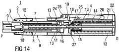
- Figure 14
- is a longitudinal section of the auto-injector with the needle shroud fully advanced and locked in forward position in order to protect the needle.
- Corresponding parts are marked with the same reference symbols in all figures.
Figure 1 shows a perspective view of an auto-injector 1 with anelongate housing 2 and aneedle shroud 3 for protecting a needle (not shown). Alateral trigger button 4 may be transversally pressed in order to trigger an automatic injection. Thetrigger button 4 is interlocked with theneedle shroud 3 so it cannot be pressed until theneedle shroud 3 is pushed into thehousing 2 by placing it on an injection site, e.g. a patient's skin and applying pressure. Theneedle shroud 3 haslongitudinal splines 5 engaged in corresponding grooves in thehousing 1 for preventing relative rotation of theneedle shroud 3 with respect to thehousing 1. Aviewing window 6 allows for viewing and inspecting a syringe held in the auto-injector 1.Figure 2 shows a longitudinal section of the auto-injector 1 in a prior to use state. Asyringe 7 is partially surrounded and supported at a front end by asyringe carrier 8. Attached at the front end of thesyringe 7 is ahollow needle 9 for piercing a patient's skin and delivering a liquid medicament M stored inside thesyringe 7. Near the distal end of the syringe 7 abung 10 is arranged for sealing and containing the medicament. The bung 10 may be advanced by apiston rod 11 in order to expel the medicament M from thesyringe 7. Thesyringe carrier 8 is slidably arranged inside theneedle shroud 3. Theneedle shroud 3 is biased by acompression spring 12 towards a proximal end P. A bayonet fit (shown infigure 11 ) between theneedle shroud 3 and an outerrear tube 13 serves for holding theneedle shroud 3 in a retracted position against the bias of thecompression spring 12 prior to use, thus enabling the patient to grab and remove the rubber needle shield (not shown).- A
torsion spring 14 is arranged inside the outerrear tube 13 and with one end attached to a distal end D of thehousing 2 so torque from thetorsion spring 14 is reacted into thehousing 2. The other end of thetorsion spring 14 is coupled to alead nut 15 which is rotatably mounted around thepiston rod 11. Thepiston rod 11 has an externallead screw thread 16 engaged with thelead nut 15. Thelead nut 15 is equipped with at least oneball bearing 17 for this engagement. It could alternatively have at least one pin. In the prior to use state shown infigure 2 thelead nut 15 is biased by thetorsion spring 14 but kept from rotating by a lockingpin 18 arranged at thetrigger button 4 engaged with adog tooth 19 arranged at thelead nut 15. An innerrear tube 20 is arranged inside thetorsion spring 14 and around thepiston rod 11 and part of thelead nut 15. Thepiston rod 11 is guided along ashaft 21 arranged in an axial bore of thepiston rod 11. The axial bore and theshaft 21 both have a non-circular profile in order to keep thepiston rod 11 from rotating, e.g. a square profile or a profile with at least one spline or flat. Theshaft 21 is attached to anend cap 22 arranged at the distal end D of the auto-injector 1. - A protective needle shield (not shown) may be provided which has to be removed prior to use by a user resulting in the situation of
figure 1 . In this situation theneedle 9 is a safe distance back within the needle shroud to protect the user from accidental needlestick injuries. Figure 3 shows a perspective detail view of the longitudinal section offigure 2 with theneedle shroud 3 and thetrigger button 4 interlocked bycatches needle shroud 3 and thetrigger button 4, respectively.- In order to prepare for an injection the user pushes the proximal end P of the auto-
injector 1 against the injection site. Thus theneedle shroud 3 is moved into the auto-injector 1 by a small distance big enough to release the interlocking catches 24, 25 from each other. This situation is shown infigure 4 . Thecompression spring 12 opposes the motion of theneedle shroud 3 but is specified such that its spring rate and preload are low enough to feel natural for the user. Thetrigger button 4 may now be operated. Figure 5 shows the distal end of thetrigger button 4 being pressed thus rotating thetrigger button 4 about atrigger pivot 26 in thehousing 2, raising the proximal end of thetrigger button 4 and moving the lockingpin 18 out of the engagement with thedog tooth 19 of thelead nut 15. Thus thelead nut 15 is released and torque from thetorsion spring 14 causes thelead nut 15 to rotate. Since thelead nut 15 abuts against athrust face 27 in thehousing 2 it is kept from moving in distal direction D due to the load applied to thepiston rod 11 while rotating.- Instead, as shown in
figure 6 , thepiston rod 11, kept from rotating by theshaft 21, is pushed forward in proximal direction P due to the engagement of thelead nut 15 and thelead screw thread 16. The advancingpiston rod 11 pushes against the bung 10 which in turn advances thesyringe 7 by virtue of the friction between the bung 10 and the syringe wall and due to the thin fluid channel inside thehollow needle 9 opposing the displacement of the medicament M.The advancing syringe 7 also causes theneedle 9 to protrude beyond the proximal end P of the auto-injector 1 into the injection site, e.g. the patient's skin. Since thesyringe 7 is supported at its proximal end by an orifice of thesyringe carrier 8 thesyringe carrier 8 is also advanced with thesyringe 7 until thesyringe carrier 8 abuts against an abutment in theneedle shroud 3 as shown infigure 6 . This contact sets the injection depth relative to theneedle shroud 3. Figure 7 is a detail view of the longitudinal section offigure 6 .- After the
syringe carrier 8 has hit the abutment of theneedle shroud 3 thesyringe 7 is kept from advancing further. With thelead nut 15 still rotating and pushing thepiston rod 11 thebung 10 overcomes the friction and the hydraulic resistance of the medicament M and advances inside thesyringe 7 thereby displacing the medicament M and delivering it through the fluid channel of thehollow needle 9 into or through the patient's skin. This situation is shown infigure 8 . Figure 8 shows thepiston rod 11 and the bung 10 almost fully advanced and thesyringe 7 almost entirely emptied but for a small residue. Referring now tofigures 9 and 10a and10b showing different detail views of the cutout marked infigure 8 , just before the bung 10 bottoms out in the syringe 7 ashoulder 28 on the distal end of thepiston rod 11 behind thelead screw thread 15 is pushed intoclutch fingers 29 on the distal end of thelead nut 15 thereby bending theclutch fingers 29 radially outward. Eachclutch finger 29 has anexternal tooth 30 which now engages with a respective internallongitudinal spline 31 provided in the proximal end of the innerrear tube 20, causing the innerrear tube 20 to rotate along with thelead nut 15. Thesplines 31 are arranged in a ratchet manner infigure 10a .Figure 10b shows an alternative embodiment withrounded finger teeth 30. In both embodiments (fig 10a and10 b ) the clutch mechanism is arranged to let theclutch fingers 29 generate enough torque on thelongitudinal splines 31 to partially rotate the outerrear tube 13 to release a bayonet fit described below infigure 11 . However the torque generated has to be low enough to let thelead nut 15 continue rotating with the spring arms jumping over thesplines 31 and making a rattling noise indicating that the injection has been nearly finished. The innerrear tube 20 is coupled with the outerrear tube 13 near the distal end D of the auto-injector 1 (cf.fig. 8 ). Thus the outerrear tube 13 is also rotated. Theouter tube 13 has a circumferential slot (not illustrated) to allow the distal end of the torsion spring to pass through to thehousing 2 for grounding thetorsion spring 14. The circumferential slot has to be long enough to allow a partial rotation of the outerrear tube 13 in order to disengage the bayonet fit described below infigure 11 .Figure 11 shows a perspective view of the auto-injector 1 just before the engagement of theclutch fingers 29 with the internallongitudinal splines 31. The bayonet fit between apin 32 of theneedle shroud 3 and apin track 33 of the outerrear tube 13 is still in a state with thepin 32 behind atrack shoulder 34 so theneedle shroud 3 would be held in position against the bias of thecompression spring 12 if the stilldepressed needle shroud 3 was released. A small axial clearance behind thetrack shoulder 34 allows theneedle shroud 3 to be pushed in distal direction D just enough to disengage the interlock between thebutton 4 and theneedle shroud 3 as described above.- When the
clutch fingers 29 are engaged with the internallongitudinal splines 31 the outerrear tube 13 is rotated so as to disengage the bayonet fit by thepin 32 coming clear of thetrack shoulder 34 so theneedle shroud 3 may be pushed forward by the compression spring 12 (seefig. 12 ). At this point the user is asked to keep pressure with the auto-injector 1 at the injection site for a short period of time, e.g. ten seconds. During this time thelead nut 15 is still rotating and forwarding thepiston rod 11 andbung 10 until the bung 10 bottoms out at the proximal end of thesyringe 7 thereby virtually entirely displacing the rest of the medicament M from thesyringe 7. - As the user withdraws the auto-
injector 1 from the injection site theneedle shroud 3 is pushed over theneedle 9 in proximal direction P by thecompression spring 12. This situation is shown infigures 13 and14 . A locking mechanism, such as a unidirectional barb or other known to those skilled in the art, may be provided to lock theneedle shroud 3 in this forward position in order to prevent re-exposure of the needle. - The auto-
injector 1 may preferably be used for delivering one of an analgetic, an anticoagulant, insulin, an insulin derivate, heparin, Lovenox, a vaccine, a growth hormone, a peptide hormone, a proteine, antibodies and complex carbohydrates. - 1
- auto-injector
- 2
- housing
- 3
- needle shroud
- 4
- trigger button, activating means
- 5
- spline
- 6
- viewing window
- 7
- syringe, medicament container
- 8
- syringe carrier
- 9
- hollow needle
- 10
- bung
- 11
- piston rod, second gear member
- 12
- compression spring, second spring means
- 13
- outer rear tube
- 14
- torsion spring, spring means
- 15
- lead nut, first gear member
- 16
- lead screw thread
- 17
- ball bearings
- 18
- locking pin
- 19
- dog tooth
- 20
- inner rear tube
- 21
- shaft
- 22
- end cap
- 23
- button pivot
- 24
- catch
- 25
- catch
- 26
- trigger pivot
- 27
- thrust face
- 28
- shoulder
- 29
- clutch finger
- 30
- external tooth
- 31
- internal longitudinal spline
- 32
- bayonet pin
- 33
- pin track
- 34
- track shoulder
- D
- distal direction, distal end
- M
- medicament
- P
- proximal direction, proximal end
Claims (13)
- Auto-injector (1) for administering a dose of a liquid medicament (M), comprising:- an elongate housing (2) arranged to contain a syringe (7) with a hollow needle (9) and a bung (10) for sealing the syringe (7) and displacing the medicament (M), the elongate housing (2) having a distal end (D) and a proximal end (P) with an orifice intended to be applied against an injection site, wherein the syringe (7) is slidably arranged with respect to the housing (2),- spring means (14) capable of, upon activation, pushing the needle (9) from a covered position inside the housing (2) into an advanced position through the orifice and past the proximal end (P) as well as operating the syringe (7) to supply the dose of medicament (M),- activating means (4) arranged to lock the spring means (14) in a pressurized state prior to manual operation and capable of, upon manual operation, releasing the spring means (14) for injection,wherein the spring means (14) is a torsion spring (14) grounded at one end in the housing (2) and at the other end in a first gear member (15) rotatable about a longitudinal axis but axially fixed, wherein the first gear member (15), upon rotation, is arranged for translatively moving a second gear member (11), the second gear member (11) being prevented from rotating relative to the housing and coupled to the bung (10) in order to push it towards the proximal end (P), wherein the first gear member (15) is engaged with the activating means (4) prior to manual operation in a manner to prevent rotation and disengaged from the activating means (4) upon manual operation, wherein the second gear member (11) is a piston rod (11) having an external lead screw thread (16), wherein the first gear member (15) is a lead nut (15) engaged with the external lead screw thread (16),characterized in that the piston rod (11) has an axial bore for slidably arranging the piston rod (11) on a shaft (21) attached to the housing (2), the axial bore and the shaft (21) having corresponding non-circular profiles, wherein the external lead screw thread (16) has a variable pitch.
- Auto-injector (1) according to claim 1,characterized in that the lead nut (15) is provided with at least one pin or with a ball bearing (17) for engaging the external lead screw thread (16).
- Auto-injector (1) according to any one of the preceding claims,characterized in that an essentially tube-shaped needle shroud (3) is arranged around the syringe (7) in the housing (2), the needle shroud (3) slidable between at least a retracted position with the needle shroud (3) almost hidden inside the housing (2) and an advanced position with the needle shroud (3) protruding from the proximal end (P) and covering the hollow needle (9) in its advanced position, wherein the needle shroud (3) is biased by a second spring means (12) towards the advanced position and locked in the retracted position by a locking means which is releasable by rotary movement transmitted from the first gear member (15) through a clutch mechanism which is engaged by the second gear member (11) shortly before the second gear member (11) is fully advanced during an injection stroke.
- Auto-injector (1) according to claim 3,characterized in that an interlock mechanism is arranged for locking the activating means (4) and preventing it from being manually operated, wherein the interlock mechanism is coupled to the needle shroud (3), wherein the interlock mechanism is releasable by pushing the needle shroud (3) a small distance into the housing (2) from the needle shroud's (3) retracted position.
- Auto-injector (1) according to any one of the preceding claims,characterized in that the activating means (4) is a trigger button (4), laterally arranged at the housing (2) and operable by being pressed transversally with respect to the longitudinal axis.
- Auto-injector (1) according to claim 5,characterized in that the trigger button (4) has a locking pin (18) engageable with at least one dog tooth (19) provided at the first gear member (15) for preventing rotation thereof in order to lock the spring means (14) in its pressurized state.
- Auto-injector (1) according to any one of the claims 3 to 6 when depending from claim 4,characterized in that the locking means has the shape of a bayonet fit between the needle shroud (3) and an outer rear tube (13) arranged around the torsion spring (14), wherein the needle shroud (3) is guided in the housing (2) in a manner to prevent relative rotation and wherein the outer rear tube (13) is coupled to the clutch mechanism, wherein the bayonet fit comprises a bayonet pin (32) arranged at one of the outer rear tube (13) or the needle shroud (3) and a pin track (33) arranged in the other one of the outer rear tube (13) or the needle shroud (3).
- Auto-injector (1) according to any one of the claims 5 to 7,characterized in that the interlock mechanism comprises respective catches (24, 25) provided at the needle shroud (3) and the trigger button (4).
- Auto-injector (1) according to any one of the preceding claims,characterized in that the syringe (7) is arranged in a syringe carrier (8) and supported by the syringe carrier (8) at a proximal end, wherein the syringe carrier (8) is slidably arranged in the needle shroud (3) and wherein an abutment is provided in the needle shroud (3) defining a maximum forward position of the syringe carrier (8).
- Auto-injector (1) according to any one of the claims 3 to 7,characterized in that the clutch mechanism comprises a circumferential shoulder (28) arranged at the second gear member (11) and at least one resilient clutch finger (29) with a respective inclined inner surface arranged at a distal end of the first gear member (15), the shoulder (28) arranged for increasingly pressing against the inclined surface thereby flexing the clutch fingers (29) outward near the end of an injection stroke, wherein the clutch mechanism further comprises an inner rear tube (20) arranged around the clutch fingers (29) inside the torsion spring (14) and attached to the outer rear tube (13) at their distal ends, the inner rear tube (14) having a number of internal longitudinal splines (31) for engaging the flexed-out clutch fingers (29).
- Auto-injector (1) according to claim 10,characterized in that the internal longitudinal splines (31) are arranged in a manner to form a ratchet when engaged with the clutch fingers (29).
- Auto-injector (1) according to any one of the claims 3 to 11 when depending from claim 4,characterized in that a locking mechanism is provided for locking the needle shroud (3) in its advanced position.
- Auto-injector (1) according to any one of the preceding claims,characterized in that at least one viewing window (6) for inspecting the syringe (7) is provided in the housing (2).
Applications Claiming Priority (4)
| Application Number | Priority Date | Filing Date | Title |
|---|---|---|---|
| EP10153985 | 2010-02-18 | ||
| US41208010P | 2010-11-10 | 2010-11-10 | |
| PCT/EP2011/052297WO2011101375A1 (en) | 2010-02-18 | 2011-02-16 | Auto-injector with a torsion spring |
| EP11703888.5AEP2536451B1 (en) | 2010-02-18 | 2011-02-16 | Auto-injector with a torsion spring |
Related Parent Applications (2)
| Application Number | Title | Priority Date | Filing Date |
|---|---|---|---|
| EP11703888.5ADivision-IntoEP2536451B1 (en) | 2010-02-18 | 2011-02-16 | Auto-injector with a torsion spring |
| EP11703888.5ADivisionEP2536451B1 (en) | 2010-02-18 | 2011-02-16 | Auto-injector with a torsion spring |
Publications (2)
| Publication Number | Publication Date |
|---|---|
| EP3338833A1 EP3338833A1 (en) | 2018-06-27 |
| EP3338833B1true EP3338833B1 (en) | 2020-07-29 |
Family
ID=42306756
Family Applications (2)
| Application Number | Title | Priority Date | Filing Date |
|---|---|---|---|
| EP18151365.6AActiveEP3338833B1 (en) | 2010-02-18 | 2011-02-16 | Auto-injector with a torsion spring |
| EP11703888.5AActiveEP2536451B1 (en) | 2010-02-18 | 2011-02-16 | Auto-injector with a torsion spring |
Family Applications After (1)
| Application Number | Title | Priority Date | Filing Date |
|---|---|---|---|
| EP11703888.5AActiveEP2536451B1 (en) | 2010-02-18 | 2011-02-16 | Auto-injector with a torsion spring |
Country Status (6)
| Country | Link |
|---|---|
| US (1) | US9636467B2 (en) |
| EP (2) | EP3338833B1 (en) |
| JP (1) | JP5805111B2 (en) |
| CA (1) | CA2789590A1 (en) |
| DK (2) | DK2536451T3 (en) |
| WO (1) | WO2011101375A1 (en) |
Families Citing this family (65)
| Publication number | Priority date | Publication date | Assignee | Title |
|---|---|---|---|---|
| WO2003068290A2 (en) | 2002-02-11 | 2003-08-21 | Antares Pharma, Inc. | Intradermal injector |
| HUE042286T2 (en) | 2005-01-24 | 2019-06-28 | Antares Pharma Inc | Needle-filled pre-filled syringe |
| WO2007131025A1 (en) | 2006-05-03 | 2007-11-15 | Antares Pharma, Inc. | Injector with adjustable dosing |
| WO2007131013A1 (en) | 2006-05-03 | 2007-11-15 | Antares Pharma, Inc. | Two-stage reconstituting injector |
| EP3636301A1 (en) | 2008-03-10 | 2020-04-15 | Antares Pharma, Inc. | Injector safety device |
| US8376993B2 (en) | 2008-08-05 | 2013-02-19 | Antares Pharma, Inc. | Multiple dosage injector |
| US12097357B2 (en) | 2008-09-15 | 2024-09-24 | West Pharma. Services IL, Ltd. | Stabilized pen injector |
| JP5732039B2 (en) | 2009-03-20 | 2015-06-10 | アンタレス・ファーマ・インコーポレーテッド | Hazardous drug injection system |
| RU2530661C2 (en)* | 2009-04-30 | 2014-10-10 | Санофи-Авентис Дойчланд Гмбх | Axially regulated connection of piston rod with piston for drive mechanism of device for medicinal substance delivery |
| TW201127435A (en)* | 2009-09-30 | 2011-08-16 | Sanofi Aventis Deutschland | Drive mechanism for a drug delivery device |
| DK2536452T3 (en) | 2010-02-18 | 2019-01-02 | Sanofi Aventis Deutschland | autoinjector |
| US9572937B2 (en)* | 2010-02-18 | 2017-02-21 | Sanofi-Aventis Deutschland Gmbh | Autoinjector having piston rod with non-circular axial bore slidably arranged on housing shaft to prevent relative rotation |
| EP2399635A1 (en) | 2010-06-28 | 2011-12-28 | Sanofi-Aventis Deutschland GmbH | Auto-injector |
| EP2468333A1 (en) | 2010-12-21 | 2012-06-27 | Sanofi-Aventis Deutschland GmbH | Auto-injector |
| EP2468330A1 (en) | 2010-12-21 | 2012-06-27 | Sanofi-Aventis Deutschland GmbH | Auto-injector |
| USRE48593E1 (en) | 2010-12-21 | 2021-06-15 | Sanofi-Aventis Deutschland Gmbh | Auto-injector |
| EP2489389A1 (en)* | 2011-02-18 | 2012-08-22 | Sanofi-Aventis Deutschland GmbH | Detent mechanism |
| EP2489385A1 (en) | 2011-02-18 | 2012-08-22 | Sanofi-Aventis Deutschland GmbH | Auto-injector |
| US8496619B2 (en) | 2011-07-15 | 2013-07-30 | Antares Pharma, Inc. | Injection device with cammed ram assembly |
| US9220660B2 (en) | 2011-07-15 | 2015-12-29 | Antares Pharma, Inc. | Liquid-transfer adapter beveled spike |
| EP2606924A1 (en)* | 2011-12-21 | 2013-06-26 | Sanofi-Aventis Deutschland GmbH | Autoinjector having a retracting syringe carrier |
| EP2606925A1 (en)* | 2011-12-21 | 2013-06-26 | Sanofi-Aventis Deutschland GmbH | Autoinjector |
| US9486583B2 (en) | 2012-03-06 | 2016-11-08 | Antares Pharma, Inc. | Prefilled syringe with breakaway force feature |
| EP4186545A1 (en) | 2012-04-06 | 2023-05-31 | Antares Pharma, Inc. | Needle assisted jet injection administration of testosterone compositions |
| US9364610B2 (en) | 2012-05-07 | 2016-06-14 | Antares Pharma, Inc. | Injection device with cammed ram assembly |
| FI3659647T3 (en) | 2013-02-11 | 2024-03-28 | Antares Pharma Inc | NEEDLE-ASSISTED SPRAY INJECTOR WITH REDUCED TRIGGER FORCE |
| CN103170038B (en)* | 2013-02-22 | 2014-12-31 | 杭州金源生物技术有限公司 | Insulin injection pen |
| CA2905031C (en) | 2013-03-11 | 2018-01-23 | Hans PFLAUMER | Dosage injector with pinion system |
| WO2014165136A1 (en) | 2013-03-12 | 2014-10-09 | Antares Pharma, Inc. | Constant volume prefilled syringes and kits thereof |
| EP2823841A1 (en) | 2013-07-09 | 2015-01-14 | Sanofi-Aventis Deutschland GmbH | Autoinjector |
| GB201313888D0 (en) | 2013-08-02 | 2013-09-18 | Consort Medical Plc | Assembly for an autoinjector device |
| AU356724S (en)* | 2013-09-20 | 2014-08-01 | Bayer Pharma AG | Electronic autoinjector |
| AU354958S (en)* | 2013-09-20 | 2014-04-15 | Bayer Pharma AG | Electronic autoinjector |
| USD729382S1 (en)* | 2013-09-30 | 2015-05-12 | Shl Group Ab | Trigger for a medical injector |
| TWI577410B (en) | 2013-10-25 | 2017-04-11 | 卡貝歐洲有限公司 | Trigger mechanism of auto injector |
| EP2923714A1 (en) | 2014-03-28 | 2015-09-30 | Sanofi-Aventis Deutschland GmbH | Autoinjector triggered by skin contact |
| CN106470717B (en) | 2014-06-03 | 2020-09-11 | 安姆根有限公司 | Drug delivery system and method of use |
| GB201416985D0 (en)* | 2014-09-26 | 2014-11-12 | Ucb Biopharma Sprl And Bespak Europ Ltd | Housing part for an auto-injector |
| US11357916B2 (en) | 2014-12-19 | 2022-06-14 | Amgen Inc. | Drug delivery device with live button or user interface field |
| JP6716566B2 (en) | 2014-12-19 | 2020-07-01 | アムジエン・インコーポレーテツド | Drug delivery device with proximity sensor |
| US9415176B1 (en) | 2015-01-22 | 2016-08-16 | West Pharmaceutical Services, Inc. | Autoinjector having an end-of-dose visual indicator |
| EP3285831B1 (en)* | 2015-04-24 | 2024-05-01 | SHL Medical AG | Sub-assembly of a medicament delivery device and a medicament delivery device |
| TW201707738A (en) | 2015-06-03 | 2017-03-01 | 賽諾菲阿凡提斯德意志有限公司 | Syringe holder and autoinjector (2) |
| WO2018125629A1 (en) | 2016-12-27 | 2018-07-05 | Action Medical Technologies, Llc | Apparatuses and method for injecting medicaments |
| WO2018167498A1 (en)* | 2017-03-15 | 2018-09-20 | Owen Mumford Limited | An injection apparatus |
| ES2972207T3 (en) | 2017-07-14 | 2024-06-11 | Amgen Inc | Needle insertion-retraction system with double torsion spring system |
| US11648351B2 (en) | 2017-11-20 | 2023-05-16 | Novo Nordisk A/S | Power unit for drug delivery device |
| US10357619B1 (en) | 2018-02-08 | 2019-07-23 | Chalbourne Brasington | Auto-injection device |
| CN108744075B (en)* | 2018-04-13 | 2020-10-30 | 中国人民解放军陆军军医大学第一附属医院 | Fixing device for syringe drainage |
| WO2020014292A1 (en) | 2018-07-10 | 2020-01-16 | Action Medical Technologies, Llc | Apparatuses and method for injecting medicaments |
| USD893712S1 (en) | 2019-02-15 | 2020-08-18 | Action Medical Technologies, Llc | Grip for autoinjectors |
| GB2592059A (en)* | 2020-02-14 | 2021-08-18 | Consort Medical Ltd | Improved injection device |
| US11065392B1 (en) | 2020-03-25 | 2021-07-20 | Action Medical Technologies, Llc | Apparatuses and methods for injecting medicaments |
| US11759576B2 (en) | 2020-06-05 | 2023-09-19 | Action Medical Technologies, Llc | Parenteral injection apparatus |
| US20230364347A1 (en)* | 2020-09-25 | 2023-11-16 | Becton, Dickinson And Company | Brake Tower with Biasing Components and Medical Injection Device Including the Same |
| CN115970096B (en)* | 2022-12-23 | 2025-04-25 | 中国人民解放军西部战区总医院 | A protective device for injection for nursing use |
| WO2025132624A1 (en)* | 2023-12-21 | 2025-06-26 | Sanofi | A medicament delivery device |
| WO2025132563A1 (en)* | 2023-12-21 | 2025-06-26 | Sanofi | Injector device |
| US12427266B1 (en) | 2024-03-28 | 2025-09-30 | Genzyme Corporation | Needle shroud latch for injection devices |
| US12274872B1 (en) | 2024-03-28 | 2025-04-15 | Genzyme Corporation | Collar hold detent mechanism and lock for injection devices |
| WO2025207905A1 (en)* | 2024-03-28 | 2025-10-02 | Genzyme Corporation | Needle shroud latch for injection devices |
| US12274875B1 (en)* | 2024-03-28 | 2025-04-15 | Genzyme Corporation | Needle shroud latch for injection devices |
| US12274866B1 (en) | 2024-03-28 | 2025-04-15 | Genzyme Corporation | Rotatable collar for injection devices |
| US12274871B1 (en) | 2024-03-28 | 2025-04-15 | Genzyme Corporation | Hold detent mechanism for injection devices |
| CN119112259B (en)* | 2024-11-11 | 2025-04-01 | 上海畅德医疗科技有限公司 | Medical glue conveying device and control handle thereof |
Family Cites Families (14)
| Publication number | Priority date | Publication date | Assignee | Title |
|---|---|---|---|---|
| AU2001281753A1 (en) | 2000-08-29 | 2002-03-13 | Novo-Nordisk A/S | Automatic injection device with torsion function for retraction of needle |
| US20030105430A1 (en)* | 2001-11-30 | 2003-06-05 | Elan Pharma International Limited Wil House | Automatic injector |
| JP2006507061A (en) | 2002-11-25 | 2006-03-02 | テクファーマ・ライセンシング・アクチェンゲゼルシャフト | Automatic injection device with resettable release safety device |
| US7449012B2 (en) | 2004-08-06 | 2008-11-11 | Meridian Medical Technologies, Inc. | Automatic injector |
| EP1728529B2 (en) | 2005-06-01 | 2016-07-27 | SHL Group AB | Device for delivering medicament |
| ES2423199T3 (en)* | 2005-06-01 | 2013-09-18 | Shl Group Ab | Device to deliver medication |
| DE102005025424A1 (en) | 2005-06-02 | 2006-12-07 | Tecpharma Licensing Ag | Injection device, especially automatic injector or injection pen, has drive-off member propelled by surrounding torsional spring, for efficient delivery of product to patient |
| EP2164544A1 (en) | 2007-07-06 | 2010-03-24 | Novo Nordisk A/S | Automatic injection device |
| US8038649B2 (en) | 2007-09-18 | 2011-10-18 | Shl Group Ab | Automatic injection device with needle insertion |
| GB0724944D0 (en) | 2007-12-20 | 2008-01-30 | Ucb Pharma Sa | Auto injector |
| GB0802351D0 (en) | 2008-02-08 | 2008-03-12 | Owen Mumford Ltd | Injection devices |
| GB2460398A (en) | 2008-05-20 | 2009-12-02 | Owen Mumford Ltd | Auto-injector having a magnetic injection indicator and a needle sheath retainer |
| GB2461088B (en) | 2008-06-19 | 2012-09-26 | Cilag Gmbh Int | Injection device |
| DK2536453T3 (en) | 2010-02-18 | 2014-11-24 | Sanofi Aventis Deutschland | autoinjector |
- 2011
- 2011-02-16EPEP18151365.6Apatent/EP3338833B1/enactiveActive
- 2011-02-16JPJP2012553299Apatent/JP5805111B2/enactiveActive
- 2011-02-16WOPCT/EP2011/052297patent/WO2011101375A1/enactiveApplication Filing
- 2011-02-16CACA 2789590patent/CA2789590A1/ennot_activeAbandoned
- 2011-02-16DKDK11703888.5Tpatent/DK2536451T3/enactive
- 2011-02-16USUS13/579,455patent/US9636467B2/enactiveActive
- 2011-02-16DKDK18151365.6Tpatent/DK3338833T3/enactive
- 2011-02-16EPEP11703888.5Apatent/EP2536451B1/enactiveActive
Non-Patent Citations (1)
| Title |
|---|
| None* |
Also Published As
| Publication number | Publication date |
|---|---|
| DK3338833T3 (en) | 2020-10-19 |
| US9636467B2 (en) | 2017-05-02 |
| JP5805111B2 (en) | 2015-11-04 |
| JP2013519471A (en) | 2013-05-30 |
| EP2536451B1 (en) | 2018-03-28 |
| WO2011101375A1 (en) | 2011-08-25 |
| CA2789590A1 (en) | 2011-08-25 |
| EP2536451A1 (en) | 2012-12-26 |
| US20130123710A1 (en) | 2013-05-16 |
| EP3338833A1 (en) | 2018-06-27 |
| DK2536451T3 (en) | 2018-07-16 |
Similar Documents
| Publication | Publication Date | Title |
|---|---|---|
| EP3338833B1 (en) | Auto-injector with a torsion spring | |
| EP2624884B1 (en) | Auto injector with a torsion spring | |
| EP2624891B1 (en) | Auto-injector | |
| EP2654829B1 (en) | Auto-injector | |
| EP2654844B1 (en) | Auto-injector | |
| EP2654842B1 (en) | Auto-injector | |
| EP2654837B1 (en) | Auto-injector | |
| EP2536454B1 (en) | Autoinjector with a delay mecanism | |
| EP2654830B1 (en) | Back-end device for an auto-injector and auto-injector | |
| EP2585139B1 (en) | Needle safety arrangement and method for operating it |
Legal Events
| Date | Code | Title | Description |
|---|---|---|---|
| PUAI | Public reference made under article 153(3) epc to a published international application that has entered the european phase | Free format text:ORIGINAL CODE: 0009012 | |
| STAA | Information on the status of an ep patent application or granted ep patent | Free format text:STATUS: THE APPLICATION HAS BEEN PUBLISHED | |
| AC | Divisional application: reference to earlier application | Ref document number:2536451 Country of ref document:EP Kind code of ref document:P | |
| AK | Designated contracting states | Kind code of ref document:A1 Designated state(s):AL AT BE BG CH CY CZ DE DK EE ES FI FR GB GR HR HU IE IS IT LI LT LU LV MC MK MT NL NO PL PT RO RS SE SI SK SM TR | |
| AX | Request for extension of the european patent | Extension state:BA ME | |
| STAA | Information on the status of an ep patent application or granted ep patent | Free format text:STATUS: REQUEST FOR EXAMINATION WAS MADE | |
| 17P | Request for examination filed | Effective date:20181207 | |
| RBV | Designated contracting states (corrected) | Designated state(s):AL AT BE BG CH CY CZ DE DK EE ES FI FR GB GR HR HU IE IS IT LI LT LU LV MC MK MT NL NO PL PT RO RS SE SI SK SM TR | |
| RAX | Requested extension states of the european patent have changed | Extension state:BA Payment date:20190102 Extension state:ME Payment date:20190102 | |
| GRAP | Despatch of communication of intention to grant a patent | Free format text:ORIGINAL CODE: EPIDOSNIGR1 | |
| STAA | Information on the status of an ep patent application or granted ep patent | Free format text:STATUS: GRANT OF PATENT IS INTENDED | |
| RIC1 | Information provided on ipc code assigned before grant | Ipc:A61M 5/00 20060101ALN20200203BHEP Ipc:A61M 5/32 20060101ALI20200203BHEP Ipc:A61M 5/20 20060101AFI20200203BHEP | |
| INTG | Intention to grant announced | Effective date:20200219 | |
| GRAS | Grant fee paid | Free format text:ORIGINAL CODE: EPIDOSNIGR3 | |
| GRAA | (expected) grant | Free format text:ORIGINAL CODE: 0009210 | |
| STAA | Information on the status of an ep patent application or granted ep patent | Free format text:STATUS: THE PATENT HAS BEEN GRANTED | |
| AC | Divisional application: reference to earlier application | Ref document number:2536451 Country of ref document:EP Kind code of ref document:P | |
| AK | Designated contracting states | Kind code of ref document:B1 Designated state(s):AL AT BE BG CH CY CZ DE DK EE ES FI FR GB GR HR HU IE IS IT LI LT LU LV MC MK MT NL NO PL PT RO RS SE SI SK SM TR | |
| AX | Request for extension of the european patent | Extension state:BA ME | |
| REG | Reference to a national code | Ref country code:CH Ref legal event code:EP | |
| REG | Reference to a national code | Ref country code:AT Ref legal event code:REF Ref document number:1295044 Country of ref document:AT Kind code of ref document:T Effective date:20200815 | |
| REG | Reference to a national code | Ref country code:IE Ref legal event code:FG4D | |
| REG | Reference to a national code | Ref country code:DE Ref legal event code:R096 Ref document number:602011068033 Country of ref document:DE | |
| REG | Reference to a national code | Ref country code:DK Ref legal event code:T3 Effective date:20201013 | |
| REG | Reference to a national code | Ref country code:LT Ref legal event code:MG4D | |
| REG | Reference to a national code | Ref country code:NL Ref legal event code:MP Effective date:20200729 | |
| REG | Reference to a national code | Ref country code:AT Ref legal event code:MK05 Ref document number:1295044 Country of ref document:AT Kind code of ref document:T Effective date:20200729 | |
| PG25 | Lapsed in a contracting state [announced via postgrant information from national office to epo] | Ref country code:NO Free format text:LAPSE BECAUSE OF FAILURE TO SUBMIT A TRANSLATION OF THE DESCRIPTION OR TO PAY THE FEE WITHIN THE PRESCRIBED TIME-LIMIT Effective date:20201029 Ref country code:BG Free format text:LAPSE BECAUSE OF FAILURE TO SUBMIT A TRANSLATION OF THE DESCRIPTION OR TO PAY THE FEE WITHIN THE PRESCRIBED TIME-LIMIT Effective date:20201029 Ref country code:ES Free format text:LAPSE BECAUSE OF FAILURE TO SUBMIT A TRANSLATION OF THE DESCRIPTION OR TO PAY THE FEE WITHIN THE PRESCRIBED TIME-LIMIT Effective date:20200729 Ref country code:HR Free format text:LAPSE BECAUSE OF FAILURE TO SUBMIT A TRANSLATION OF THE DESCRIPTION OR TO PAY THE FEE WITHIN THE PRESCRIBED TIME-LIMIT Effective date:20200729 Ref country code:PT Free format text:LAPSE BECAUSE OF FAILURE TO SUBMIT A TRANSLATION OF THE DESCRIPTION OR TO PAY THE FEE WITHIN THE PRESCRIBED TIME-LIMIT Effective date:20201130 Ref country code:SE Free format text:LAPSE BECAUSE OF FAILURE TO SUBMIT A TRANSLATION OF THE DESCRIPTION OR TO PAY THE FEE WITHIN THE PRESCRIBED TIME-LIMIT Effective date:20200729 Ref country code:FI Free format text:LAPSE BECAUSE OF FAILURE TO SUBMIT A TRANSLATION OF THE DESCRIPTION OR TO PAY THE FEE WITHIN THE PRESCRIBED TIME-LIMIT Effective date:20200729 Ref country code:LT Free format text:LAPSE BECAUSE OF FAILURE TO SUBMIT A TRANSLATION OF THE DESCRIPTION OR TO PAY THE FEE WITHIN THE PRESCRIBED TIME-LIMIT Effective date:20200729 Ref country code:GR Free format text:LAPSE BECAUSE OF FAILURE TO SUBMIT A TRANSLATION OF THE DESCRIPTION OR TO PAY THE FEE WITHIN THE PRESCRIBED TIME-LIMIT Effective date:20201030 Ref country code:AT Free format text:LAPSE BECAUSE OF FAILURE TO SUBMIT A TRANSLATION OF THE DESCRIPTION OR TO PAY THE FEE WITHIN THE PRESCRIBED TIME-LIMIT Effective date:20200729 | |
| PG25 | Lapsed in a contracting state [announced via postgrant information from national office to epo] | Ref country code:IS Free format text:LAPSE BECAUSE OF FAILURE TO SUBMIT A TRANSLATION OF THE DESCRIPTION OR TO PAY THE FEE WITHIN THE PRESCRIBED TIME-LIMIT Effective date:20201129 Ref country code:RS Free format text:LAPSE BECAUSE OF FAILURE TO SUBMIT A TRANSLATION OF THE DESCRIPTION OR TO PAY THE FEE WITHIN THE PRESCRIBED TIME-LIMIT Effective date:20200729 Ref country code:PL Free format text:LAPSE BECAUSE OF FAILURE TO SUBMIT A TRANSLATION OF THE DESCRIPTION OR TO PAY THE FEE WITHIN THE PRESCRIBED TIME-LIMIT Effective date:20200729 Ref country code:LV Free format text:LAPSE BECAUSE OF FAILURE TO SUBMIT A TRANSLATION OF THE DESCRIPTION OR TO PAY THE FEE WITHIN THE PRESCRIBED TIME-LIMIT Effective date:20200729 | |
| PG25 | Lapsed in a contracting state [announced via postgrant information from national office to epo] | Ref country code:NL Free format text:LAPSE BECAUSE OF FAILURE TO SUBMIT A TRANSLATION OF THE DESCRIPTION OR TO PAY THE FEE WITHIN THE PRESCRIBED TIME-LIMIT Effective date:20200729 | |
| PG25 | Lapsed in a contracting state [announced via postgrant information from national office to epo] | Ref country code:SM Free format text:LAPSE BECAUSE OF FAILURE TO SUBMIT A TRANSLATION OF THE DESCRIPTION OR TO PAY THE FEE WITHIN THE PRESCRIBED TIME-LIMIT Effective date:20200729 Ref country code:EE Free format text:LAPSE BECAUSE OF FAILURE TO SUBMIT A TRANSLATION OF THE DESCRIPTION OR TO PAY THE FEE WITHIN THE PRESCRIBED TIME-LIMIT Effective date:20200729 Ref country code:RO Free format text:LAPSE BECAUSE OF FAILURE TO SUBMIT A TRANSLATION OF THE DESCRIPTION OR TO PAY THE FEE WITHIN THE PRESCRIBED TIME-LIMIT Effective date:20200729 Ref country code:CZ Free format text:LAPSE BECAUSE OF FAILURE TO SUBMIT A TRANSLATION OF THE DESCRIPTION OR TO PAY THE FEE WITHIN THE PRESCRIBED TIME-LIMIT Effective date:20200729 Ref country code:IT Free format text:LAPSE BECAUSE OF FAILURE TO SUBMIT A TRANSLATION OF THE DESCRIPTION OR TO PAY THE FEE WITHIN THE PRESCRIBED TIME-LIMIT Effective date:20200729 | |
| REG | Reference to a national code | Ref country code:DE Ref legal event code:R097 Ref document number:602011068033 Country of ref document:DE | |
| PG25 | Lapsed in a contracting state [announced via postgrant information from national office to epo] | Ref country code:AL Free format text:LAPSE BECAUSE OF FAILURE TO SUBMIT A TRANSLATION OF THE DESCRIPTION OR TO PAY THE FEE WITHIN THE PRESCRIBED TIME-LIMIT Effective date:20200729 | |
| PLBE | No opposition filed within time limit | Free format text:ORIGINAL CODE: 0009261 | |
| STAA | Information on the status of an ep patent application or granted ep patent | Free format text:STATUS: NO OPPOSITION FILED WITHIN TIME LIMIT | |
| PG25 | Lapsed in a contracting state [announced via postgrant information from national office to epo] | Ref country code:SK Free format text:LAPSE BECAUSE OF FAILURE TO SUBMIT A TRANSLATION OF THE DESCRIPTION OR TO PAY THE FEE WITHIN THE PRESCRIBED TIME-LIMIT Effective date:20200729 | |
| 26N | No opposition filed | Effective date:20210430 | |
| PG25 | Lapsed in a contracting state [announced via postgrant information from national office to epo] | Ref country code:SI Free format text:LAPSE BECAUSE OF FAILURE TO SUBMIT A TRANSLATION OF THE DESCRIPTION OR TO PAY THE FEE WITHIN THE PRESCRIBED TIME-LIMIT Effective date:20200729 | |
| PG25 | Lapsed in a contracting state [announced via postgrant information from national office to epo] | Ref country code:MC Free format text:LAPSE BECAUSE OF FAILURE TO SUBMIT A TRANSLATION OF THE DESCRIPTION OR TO PAY THE FEE WITHIN THE PRESCRIBED TIME-LIMIT Effective date:20200729 | |
| REG | Reference to a national code | Ref country code:BE Ref legal event code:MM Effective date:20210228 | |
| PG25 | Lapsed in a contracting state [announced via postgrant information from national office to epo] | Ref country code:LU Free format text:LAPSE BECAUSE OF NON-PAYMENT OF DUE FEES Effective date:20210216 | |
| PG25 | Lapsed in a contracting state [announced via postgrant information from national office to epo] | Ref country code:IE Free format text:LAPSE BECAUSE OF NON-PAYMENT OF DUE FEES Effective date:20210216 | |
| PG25 | Lapsed in a contracting state [announced via postgrant information from national office to epo] | Ref country code:BE Free format text:LAPSE BECAUSE OF NON-PAYMENT OF DUE FEES Effective date:20210228 | |
| PG25 | Lapsed in a contracting state [announced via postgrant information from national office to epo] | Ref country code:CY Free format text:LAPSE BECAUSE OF FAILURE TO SUBMIT A TRANSLATION OF THE DESCRIPTION OR TO PAY THE FEE WITHIN THE PRESCRIBED TIME-LIMIT Effective date:20200729 | |
| P01 | Opt-out of the competence of the unified patent court (upc) registered | Effective date:20230421 | |
| PG25 | Lapsed in a contracting state [announced via postgrant information from national office to epo] | Ref country code:HU Free format text:LAPSE BECAUSE OF FAILURE TO SUBMIT A TRANSLATION OF THE DESCRIPTION OR TO PAY THE FEE WITHIN THE PRESCRIBED TIME-LIMIT; INVALID AB INITIO Effective date:20110216 | |
| PG25 | Lapsed in a contracting state [announced via postgrant information from national office to epo] | Ref country code:MK Free format text:LAPSE BECAUSE OF FAILURE TO SUBMIT A TRANSLATION OF THE DESCRIPTION OR TO PAY THE FEE WITHIN THE PRESCRIBED TIME-LIMIT Effective date:20200729 | |
| PG25 | Lapsed in a contracting state [announced via postgrant information from national office to epo] | Ref country code:MT Free format text:LAPSE BECAUSE OF FAILURE TO SUBMIT A TRANSLATION OF THE DESCRIPTION OR TO PAY THE FEE WITHIN THE PRESCRIBED TIME-LIMIT Effective date:20200729 | |
| PGFP | Annual fee paid to national office [announced via postgrant information from national office to epo] | Ref country code:GB Payment date:20241227 Year of fee payment:15 | |
| PGFP | Annual fee paid to national office [announced via postgrant information from national office to epo] | Ref country code:FR Payment date:20241209 Year of fee payment:15 | |
| PGFP | Annual fee paid to national office [announced via postgrant information from national office to epo] | Ref country code:DE Payment date:20241224 Year of fee payment:15 | |
| PGFP | Annual fee paid to national office [announced via postgrant information from national office to epo] | Ref country code:DK Payment date:20250214 Year of fee payment:15 | |
| PGFP | Annual fee paid to national office [announced via postgrant information from national office to epo] | Ref country code:CH Payment date:20250301 Year of fee payment:15 | |
| PGFP | Annual fee paid to national office [announced via postgrant information from national office to epo] | Ref country code:TR Payment date:20250130 Year of fee payment:15 | |
| REG | Reference to a national code | Ref country code:DE Ref legal event code:R082 Ref document number:602011068033 Country of ref document:DE |