EP3338604B1 - Handheld kitchen appliance assembly - Google Patents
Handheld kitchen appliance assemblyDownload PDFInfo
- Publication number
- EP3338604B1 EP3338604B1EP17204725.0AEP17204725AEP3338604B1EP 3338604 B1EP3338604 B1EP 3338604B1EP 17204725 AEP17204725 AEP 17204725AEP 3338604 B1EP3338604 B1EP 3338604B1
- Authority
- EP
- European Patent Office
- Prior art keywords
- drive unit
- tool
- cradles
- charging unit
- cradle
- Prior art date
- Legal status (The legal status is an assumption and is not a legal conclusion. Google has not performed a legal analysis and makes no representation as to the accuracy of the status listed.)
- Active
Links
Images


Classifications
- B—PERFORMING OPERATIONS; TRANSPORTING
- B25—HAND TOOLS; PORTABLE POWER-DRIVEN TOOLS; MANIPULATORS
- B25F—COMBINATION OR MULTI-PURPOSE TOOLS NOT OTHERWISE PROVIDED FOR; DETAILS OR COMPONENTS OF PORTABLE POWER-DRIVEN TOOLS NOT PARTICULARLY RELATED TO THE OPERATIONS PERFORMED AND NOT OTHERWISE PROVIDED FOR
- B25F3/00—Associations of tools for different working operations with one portable power-drive means; Adapters therefor
- A—HUMAN NECESSITIES
- A47—FURNITURE; DOMESTIC ARTICLES OR APPLIANCES; COFFEE MILLS; SPICE MILLS; SUCTION CLEANERS IN GENERAL
- A47J—KITCHEN EQUIPMENT; COFFEE MILLS; SPICE MILLS; APPARATUS FOR MAKING BEVERAGES
- A47J43/00—Implements for preparing or holding food, not provided for in other groups of this subclass
- A47J43/04—Machines for domestic use not covered elsewhere, e.g. for grinding, mixing, stirring, kneading, emulsifying, whipping or beating foodstuffs, e.g. power-driven
- A—HUMAN NECESSITIES
- A47—FURNITURE; DOMESTIC ARTICLES OR APPLIANCES; COFFEE MILLS; SPICE MILLS; SUCTION CLEANERS IN GENERAL
- A47J—KITCHEN EQUIPMENT; COFFEE MILLS; SPICE MILLS; APPARATUS FOR MAKING BEVERAGES
- A47J42/00—Coffee mills; Spice mills
- A47J42/38—Parts or details
- A47J42/46—Driving mechanisms; Coupling to drives
- A—HUMAN NECESSITIES
- A47—FURNITURE; DOMESTIC ARTICLES OR APPLIANCES; COFFEE MILLS; SPICE MILLS; SUCTION CLEANERS IN GENERAL
- A47J—KITCHEN EQUIPMENT; COFFEE MILLS; SPICE MILLS; APPARATUS FOR MAKING BEVERAGES
- A47J43/00—Implements for preparing or holding food, not provided for in other groups of this subclass
- A47J43/04—Machines for domestic use not covered elsewhere, e.g. for grinding, mixing, stirring, kneading, emulsifying, whipping or beating foodstuffs, e.g. power-driven
- A47J43/042—Mechanically-driven liquid shakers
- A—HUMAN NECESSITIES
- A47—FURNITURE; DOMESTIC ARTICLES OR APPLIANCES; COFFEE MILLS; SPICE MILLS; SUCTION CLEANERS IN GENERAL
- A47J—KITCHEN EQUIPMENT; COFFEE MILLS; SPICE MILLS; APPARATUS FOR MAKING BEVERAGES
- A47J43/00—Implements for preparing or holding food, not provided for in other groups of this subclass
- A47J43/04—Machines for domestic use not covered elsewhere, e.g. for grinding, mixing, stirring, kneading, emulsifying, whipping or beating foodstuffs, e.g. power-driven
- A47J43/044—Machines for domestic use not covered elsewhere, e.g. for grinding, mixing, stirring, kneading, emulsifying, whipping or beating foodstuffs, e.g. power-driven with tools driven from the top side
- A—HUMAN NECESSITIES
- A47—FURNITURE; DOMESTIC ARTICLES OR APPLIANCES; COFFEE MILLS; SPICE MILLS; SUCTION CLEANERS IN GENERAL
- A47J—KITCHEN EQUIPMENT; COFFEE MILLS; SPICE MILLS; APPARATUS FOR MAKING BEVERAGES
- A47J43/00—Implements for preparing or holding food, not provided for in other groups of this subclass
- A47J43/04—Machines for domestic use not covered elsewhere, e.g. for grinding, mixing, stirring, kneading, emulsifying, whipping or beating foodstuffs, e.g. power-driven
- A47J43/06—Machines for domestic use not covered elsewhere, e.g. for grinding, mixing, stirring, kneading, emulsifying, whipping or beating foodstuffs, e.g. power-driven with a plurality of interchangeable working units, e.g. with a single driving-unit
- A—HUMAN NECESSITIES
- A47—FURNITURE; DOMESTIC ARTICLES OR APPLIANCES; COFFEE MILLS; SPICE MILLS; SUCTION CLEANERS IN GENERAL
- A47J—KITCHEN EQUIPMENT; COFFEE MILLS; SPICE MILLS; APPARATUS FOR MAKING BEVERAGES
- A47J43/00—Implements for preparing or holding food, not provided for in other groups of this subclass
- A47J43/04—Machines for domestic use not covered elsewhere, e.g. for grinding, mixing, stirring, kneading, emulsifying, whipping or beating foodstuffs, e.g. power-driven
- A47J43/07—Parts or details, e.g. mixing tools, whipping tools
- A47J43/08—Driving mechanisms
- A47J43/082—Driving mechanisms for machines with tools driven from the upper side
- A—HUMAN NECESSITIES
- A47—FURNITURE; DOMESTIC ARTICLES OR APPLIANCES; COFFEE MILLS; SPICE MILLS; SUCTION CLEANERS IN GENERAL
- A47J—KITCHEN EQUIPMENT; COFFEE MILLS; SPICE MILLS; APPARATUS FOR MAKING BEVERAGES
- A47J43/00—Implements for preparing or holding food, not provided for in other groups of this subclass
- A47J43/10—Egg-whisks; Cream-beaters, i.e. hand implements or hand-driven devices
- A—HUMAN NECESSITIES
- A47—FURNITURE; DOMESTIC ARTICLES OR APPLIANCES; COFFEE MILLS; SPICE MILLS; SUCTION CLEANERS IN GENERAL
- A47J—KITCHEN EQUIPMENT; COFFEE MILLS; SPICE MILLS; APPARATUS FOR MAKING BEVERAGES
- A47J43/00—Implements for preparing or holding food, not provided for in other groups of this subclass
- A47J43/27—Implements for preparing or holding food, not provided for in other groups of this subclass for mixing drinks; Hand-held shakers
- B—PERFORMING OPERATIONS; TRANSPORTING
- B25—HAND TOOLS; PORTABLE POWER-DRIVEN TOOLS; MANIPULATORS
- B25F—COMBINATION OR MULTI-PURPOSE TOOLS NOT OTHERWISE PROVIDED FOR; DETAILS OR COMPONENTS OF PORTABLE POWER-DRIVEN TOOLS NOT PARTICULARLY RELATED TO THE OPERATIONS PERFORMED AND NOT OTHERWISE PROVIDED FOR
- B25F5/00—Details or components of portable power-driven tools not particularly related to the operations performed and not otherwise provided for
- B25F5/02—Construction of casings, bodies or handles
- A—HUMAN NECESSITIES
- A47—FURNITURE; DOMESTIC ARTICLES OR APPLIANCES; COFFEE MILLS; SPICE MILLS; SUCTION CLEANERS IN GENERAL
- A47J—KITCHEN EQUIPMENT; COFFEE MILLS; SPICE MILLS; APPARATUS FOR MAKING BEVERAGES
- A47J43/00—Implements for preparing or holding food, not provided for in other groups of this subclass
- A47J43/04—Machines for domestic use not covered elsewhere, e.g. for grinding, mixing, stirring, kneading, emulsifying, whipping or beating foodstuffs, e.g. power-driven
- A47J43/044—Machines for domestic use not covered elsewhere, e.g. for grinding, mixing, stirring, kneading, emulsifying, whipping or beating foodstuffs, e.g. power-driven with tools driven from the top side
- A47J2043/04409—Apparatus of hand held type
- A47J2043/04427—Apparatus of hand held type with housing extending vertically in line with the tool axis
- A—HUMAN NECESSITIES
- A47—FURNITURE; DOMESTIC ARTICLES OR APPLIANCES; COFFEE MILLS; SPICE MILLS; SUCTION CLEANERS IN GENERAL
- A47J—KITCHEN EQUIPMENT; COFFEE MILLS; SPICE MILLS; APPARATUS FOR MAKING BEVERAGES
- A47J43/00—Implements for preparing or holding food, not provided for in other groups of this subclass
- A47J43/04—Machines for domestic use not covered elsewhere, e.g. for grinding, mixing, stirring, kneading, emulsifying, whipping or beating foodstuffs, e.g. power-driven
- A47J43/07—Parts or details, e.g. mixing tools, whipping tools
- A47J2043/0738—Means for storing accessories
Definitions
- the present inventionrelates to kitchen appliances.
- the inventionrelates to handheld kitchen appliances that are battery operated.
- Handheld kitchen appliancessuch as blenders, slicing knifes, cork screws, and can openers have evolved from a purely manual operation, with no assistance from a motor, to an automatic operation with the assistance of a motor.
- the motors of these applianceswere powered by AC power and required a power cord.
- many kitchen applianceshave been redesigned to be battery operated. Both types of motor operated appliances help automatic kitchen tasks and require less effort by the user.
- the size of the kitchen applianceshas increased due to the motor and additional parts. Therefore, these appliances require more space in cabinets or on kitchen counters.
- the battery operated appliancesprovide a benefit of being cordless, they require that the batteries be recharged or replaced. This may also require individual charging stations for each appliance, which again requires additional storage space.
- US-A-4575255describes a base for holding a detachable and portable casing to which may be attached a kitchen appliance unit, such as whisk, a spatula, a mixer or the like. These kitchen appliance units fit into receptacles whereat they are accommodated for storage, these units and the portable casing extending vertically upwards from the base.
- a unitmay be detachably inserted into the portable case which houses a gear train, as well as a motor for driving the same.
- the portable casemoreover, accommodates a rechargeable battery arrangement for driving the motor.
- a recharging unitconsisting of a secondary winding of a transformer and a coil which is encircled thereby.
- the primary winding and associated coreis accommodated in the base.
- the coresare juxtaposed in coaxial alignment, whereby an alternating current source coupled to the primary winding charges the rechargeable battery arrangement.
- a handheld kitchen appliance assemblyincluding a drive unit having a housing, a rechargeable battery disposed within the housing, and a motor disposed within the housing and powered by the battery.
- the handheld appliance assemblyalso includes a tool having an attachment portion for releasably connecting the tool to the drive unit. The tool is selectively driven by the drive unit when the tool is connected to the drive unit.
- a charging unitincludes a cavity sized and shaped to receive a portion of the drive unit.
- the charging unitincludes a power supply and is configured to send a charging current to the battery of the drive unit to recharge the battery when the drive unit is received within the cavity.
- a cradleincludes an opening sized and shaped to support the tool when the tool is disconnected from the drive unit.
- the cradleincludes a linkage that is engageable with the charging unit for selectively connecting the cradle to the charging unit.
- a base for supporting a kitchen applianceincluding a drive unit and a plurality of tools configured to be driven by the drive unit.
- the drive unithas a rechargeable battery, a motor, and a first electrical contact.
- the plurality of toolseach has a tool element and an attachment portion for releasably connecting the tool to the drive unit.
- the baseincludes a charging unit including a cavity sized and shaped to receive a portion of the drive unit to support the drive unit.
- the cavityincludes a second electrical contact, in which the second electrical contact is configured to engage with the first electrical contact of the drive unit when the drive unit is received within the charging unit.
- a power supplyis connected to the charging unit.
- the power supplyis configured to provide power to the charging unit to enable the charging unit to send a charging current to the battery of the drive unit via the first electrical contact and the second electrical contact.
- the basefurther includes a plurality of cradles for supporting the plurality of tools.
- the plurality of cradleseach includes an opening sized and shaped to receive one of the plurality of tools.
- a handheld kitchen appliance assemblyincluding a drive unit including a housing having an elongated body with a first end and a second end that is spaced apart from the first end.
- a rechargeable batteryis disposed within the housing, and a motor disposed within the housing and is powered by the battery.
- An attachment memberis positioned on the second end of the housing, and a first electrical contact is positioned on the second end of the housing. The electrical contact is configured to receive a charging current and send the charging current to the battery to recharge the battery.
- the handheld kitchen appliancefurther includes a tool including a tool element and an attachment portion. The attachment portion is configured to engage with the attachment member of the drive unit to connect the tool to the drive unit.
- the handheld kitchen appliancefurther includes a base including a charging unit having a cavity with a second electrical contact.
- the cavityis configured to receive the second end of the drive unit so that the first electrical contact of the drive unit engages with the second electrical contact of the charging unit.
- the second electrical contactis configured to send the charging current to the first electrical contact.
- the basefurther includes a cradle having an opening for receiving a portion of the tool.
- the cradleincludes a linkage that is engageable with the charging unit for selectively connecting the cradle to the charging unit.
- a handheld kitchen appliance assemblycomprising:
- the charging unitmay include a plurality of recesses, each of the recesses sized and shaped to receive the linkage of the cradle.
- the plurality of recessesmay be arranged around a perimeter of the charging unit, and the cradle may be positioned at different angles relative to the charging unit by engaging with different recesses.
- the toolmay be one of a plurality of tools.
- the cradlemay be one of a plurality of cradles, the plurality of cradles each including an opening sized and shaped to receive one of the plurality of tools.
- the linkage of each of the plurality of cradlesmay be engageable with the charging unit for selectively connecting the respective cradle to the charging unit.
- the plurality of cradlesmay be connectable to the charging unit at the same time.
- the plurality of cradlesmay each include a recess sized and shaped to receive the linkage of one of the other plurality of cradles.
- the drive unitmay include a handgrip and a user interface having a plurality of actuators for controlling the drive unit.
- the user interfacemay be positioned proximate the handgrip to enable a user to grasp the handgrip and engage with the user interface using one hand.
- a base for supporting a kitchen appliance including a drive unit and a plurality of toolsmay be configured to be driven by the drive unit.
- the drive unitmay have a rechargeable battery, a motor, and a first electrical contact.
- the plurality of toolsmay each have a tool element and attachment portion for releasably connecting the tool to the drive unit.
- the basemay comprise a charging unit including a cavity sized and shaped to receive a portion of the drive unit to support the drive unit, the cavity including a second electrical contact, the second electrical contact configured to engage with the first electrical contact of the drive unit when the drive unit is received within the charging unit.
- the basemay also comprise a power supply connected to the charging unit, the power supply configured to provide power to the charging unit to enable the charging unit to send a charging current to the battery of the drive unit via the first electrical contact and the second electrical contact.
- the basemay also comprise a plurality of cradles for supporting the plurality of tools, the plurality of cradles each including an opening sized and shaped to receive one of the plurality of tools.
- the charging unitmay be configured to support the drive unit in an upright position. At least one of the plurality of cradles may be configured to support at least one of the plurality of tools in an upright position.
- Each of the plurality of cradlesmay include a linkage engageable with the charging unit for releasably connecting the respective cradle to the charging unit.
- the charging unitmay include a plurality of recesses, each of the plurality of recesses sized and shaped to receive the linkage of one of the plurality of cradles.
- the linkages of the plurality of cradlesmay be engageable with one of the plurality of recesses.
- Each of the plurality of cradlesmay include a plurality of recesses sized and shaped to receive the linkage of another one of the plurality of cradles for releasably connecting the plurality of cradles to one another.
- the charging unitmay be connectable to more than one of the plurality of cradles at the same time.
- Each of the plurality of cradlesmay be connectable to more than one of the plurality of cradles at the same time.
- the charging unit and the plurality of cradlesmay be configurable in a plurality of different arrangements relative to one another.
- a handheld kitchen appliance assemblycomprising:
- the toolmay be one of a plurality of tools and the cradle may be one of a plurality of cradles, the plurality of cradles each including an opening sized and shaped to receive one of the plurality of tools.
- Each of the plurality of cradlesmay further include a linkage engageable with the charging unit for selectively connecting the cradle to the charging unit.
- the plurality of cradlesmay be connectable to the charging unit at the same time.
- Each of the plurality of cradlesmay include a recess sized and shaped to receive the linkage of one of the other plurality of cradles.
- the charging unitmay be configured to support the drive unit in an upright position. At least one of the plurality of cradles may be configured to support at least one of the plurality of tools in an upright position
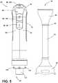
- FIGS. 1 and 2illustrate one embodiment of a kitchen appliance assembly 10.
- the kitchen appliance assembly 10includes a handheld appliance 15 having a drive unit 20 and a tool 25, and a base 30 for supporting the handheld appliance 15.
- FIGS. 3-9illustrate the handheld appliance 15 without the base 30.
- the drive unit 20 and the tool 25are separate elements that can be selectively connected and disconnected.
- FIGS. 3-5show the drive unit 20 and the tool 25 in a disconnected position
- FIGS. 6-9show the drive unit 20 and the tool 25 in a connected position.
- the tool 25can be detached from the drive unit 20 and placed on the base 30 for storage.
- the tool 25includes a first end forming an attachment portion 35 and a second end having a tool element 40.
- the attachment portion 35 and the tool element 40are spaced apart by a rod 45.
- the attachment portion 35includes a receptacle 50 that is sized and shaped to receive a portion of the drive unit 20 for connecting the tool 25 to the drive unit 20.
- the tool element 40can be any type of kitchen tool.
- FIGS. 6-9illustrate some examples of tool elements 40.
- FIG. 6illustrates a plunger blender
- FIG. 7illustrates a sauce stirrer
- FIG. 8illustrates a whisk
- FIG. 9illustrates a spice mill.
- the handheld appliance 15includes a drive unit 20 and tools 25, where each tool 25 includes a different tool element 40.
- the drive unit 20can be connected to any of the tools 25 to drive the operation of the tool 25. Then drive unit 20 is disconnected from one tool 25 and connected to a different tool 25 in order to use a tool 25 with a different tool element 40.
- the drive unit 20includes a housing 55 that supports a motor (not shown) and a rechargeable battery (not shown) for providing power to the motor.
- the housing 55is elongated and defines an axis extending between a first end 60 and a second end 65 that is spaced apart from the first end 60.
- a handgrip 70is formed on the first end 60 of the housing 55 to enable a user to grasp the drive unit 20 to operate the handheld appliance 15.
- the handgrip 70has a linear portion 75 and a curved portion 80.
- the linear portion 75can be grasped by a user's palm with the user's fingers wrapped around the linear portion 75.
- the curved portion 80extends above the user's hand to prevent the drive unit 20 from slipping out of the user's hand during operation.
- a user interface 85is also disposed on the first end 60 of the housing 55.
- the user interface 85includes controls 90 (e.g., buttons) for controlling operation of the drive unit 20.
- the illustrated user interface 85includes a power button 95, a start/stop button 100, and a speed button 105.
- the power button 95is used to turn the drive unit 20 on and to provide power to the motor.
- the start/stop button 100is used to actuate the tool 25.
- the speed button 105is used for changing speed of the tool 25.
- greater or fewer controls 90may be included in the user interface 85.
- some of the controls 90 of the user interface 85are positioned on the linear portion 75 of the handgrip 70 and some of the controls 90 are positioned on the curved portion 80 of the handgrip 70.
- the controls 90 on the linear portion 75 of the handgrip 70can be actuated by a user's fingers while maintaining a grasp on the handgrip 70.
- the controls 90 on the curved portion 80 of the handgrip 70can be actuated by a user's thumb while maintaining a grasp on the handgrip 70.
- the second end 65 of the drive unit 20engages with the tool 25 to connect the tool 25 to the drive unit 20 and to drive the operation of the tool element 40.
- an attachment member 110is disposed on the second end 65 of the housing 55 for releasably connecting the tool 25 to the drive unit 20.
- the attachment member 110enables the tool 25 to be connected and disconnected from the drive unit 20 without the use of tools.
- the attachment member 110is a detent that engages with the tool 25.
- the detentis spring biased towards a locked position, and a release button is used to move the detent against the spring bias to release the tool 25 from the drive unit 20.
- the attachment member 110is a threaded connection for screwing the drive unit 20 and the tool 25 together.
- different types quick connect mechanisms known to those skilled in the artcan be used to releasably connect the drive unit 20 and the tool 25.
- the tool 25is driven by a drive shaft 115 extending from the second end 65 of the drive unit 20.
- the drive shaft 115extends along the axis of the housing 55 in direction away from the handgrip 70.
- the drive shaft 115is driven by the motor and engages with the tool 25 to thereby drive the operation of the tool 25.
- the tool 25is fixed with respect to the drive shaft 115 so that movement of the drive shaft 115 is transferred to the tool 25.
- the base 30includes a charging unit 120 and cradles 125.
- the charging unit 120supports and charges the drive unit 20 and the cradle 125 supports the tool 25.
- FIGS. 10-14illustrate various views of the charging unit 120.
- the charging unit 120has a frustoconical shape with an open top end 130 and a closed bottom end 135.
- the open top end 130forms a cavity 140 for receiving the second end 65 of the drive unit 20.
- the cavity 140is sized and shaped to receive the second end 65 of the drive unit 20.
- the cavity 140is sized and shaped to receive the drive shaft 115 of the drive unit 20.
- the charging unit 120supports the drive unit 20 in an upright position. In other embodiments, the charging unit 120 may support the drive unit 20 in other orientations.
- the charging unit 120can be other shapes and sizes that are sufficient to support the drive unit 20.
- the charging unit 120includes a power source 145 and electrical components that are arranged to recharge the battery of the drive unit 20 when the drive unit 20 is received within the charging unit 120.
- the charging unit 120includes a power cord 145 that receives AC power and electrical components that convert the AC power to a charging current.
- An electrical contact 150is disposed within the cavity 140 of the charging unit 120 and positioned within the cavity 140 so that the contact 150 aligns with an electrical contact 155 on the drive unit 20.
- the contact 155 of the drive unit 20engages with the contact 150 of the charging unit 120, which enables the charging current to pass from the charging unit 120 to the drive unit 20 to charge the battery.
- the charging unit 120also includes recesses 160 along the bottom end 135 of the charging unit 120. As will be described in greater detail below, the recesses 160 are used to connect the cradle 125 to the charging unit 120. The recesses 160 are arranged around the perimeter of the charging unit 120, and each recess 160 is engageable with the cradle 125. In the illustrated embodiment, the charging unit 120 includes three recesses 160. However, in other embodiments, the charging unit 120 includes greater or fewer recesses 160.
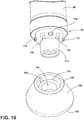
- FIGS. 15-20illustrate various views of the cradle 125.
- the cradle 125has a substantially cylindrical shape with an open top end 165 and a closed bottom end 170.
- the top end 165forms an opening 175 for receiving the tool 25.
- the opening 175is sized and shaped to receive the tool 25.
- the opening 175is sized and shaped to receive a tool 25 with a specific tool element 40.
- the opening 175is sized and shaped more generally to receive a tool 25 with any of the tool elements 40.
- the cradle 125can be other shapes and sizes that are sufficient to support the drive unit 20.
- the cradle 125includes a linkage 180 for connecting the cradle 125 to the charging unit 120.
- the linkage 180is a tab 185 with a hook 190 at the end of it.
- the tab 190extends from the bottom end 65 of the cradle 125 and extends radially outward to engage with a recess 160 on the charging unit 120.
- the linkage 180is another type of coupling member.
- the recesses 160 on the charging unit 120are sized and shaped to receive the linkage 180 of the cradle 125.
- the linkages 180can snap into and out of the recesses 160 to connect and disconnect the cradle 125 from the charging unit 120.
- the linkage 180can engage with any of the recesses 160 on the charging unit 120 in order to adjust the cradle 125 to different angles relative to the charging unit 120. Furthermore, because the charging unit 120 includes multiple recesses 160, multiple cradles 125 can be connected to the charging unit 120 at the same time. Therefore, when the handheld appliance 15 includes a plurality of tools 25, each tool 25 can be supported by a different cradle 125.
- each cradle 125includes recesses 195.
- the recesses 195are arranged around the perimeter of the cradle 125.
- Each recess 195is sized and shaped to receive a linkage 180 of one of the other cradles 125. This enables the cradles 125 to be connected to one another in addition to being connected to the charging unit 120. Similar to the charging unit 120, because the cradle 125 includes multiple recesses 195, the cradle 125 can be connected to multiple other cradles 125 at the same time. Accordingly, the base 30 can take on different arrangements depending on the number of cradles 125, and the arrangement and orientation of the cradles 125 and the charging unit 120.
- FIGS. 21-27illustrate some examples of different arrangements of the base 30.
- the base 30includes the charging unit 120 and three cradles 125.
- the charging unit 120is positioned in the front of the base 30 and the cradles 125 are connected to the charging unit 120 in a row.
- the first cradle 125ais connected to the charging unit 120
- the second cradle 125bis connected to the first cradle 125a
- the third cradle 125cis connected to the second cradle 125b.
- the charging unit 120 and the cradles 125are oriented in a linear arrangement so that the row is generally straight.
- each cradle 125are connected to a central recess 160, 195.
- the linkages 180can be connected to non-central recesses 160, 195 in order to create a wavy pattern.
- FIGS. 24-27illustrate the base 30 according to some of the other possible arrangements of the charging unit 120 and the cradles 125. These arrangements are non-exclusive examples of how to arrange the charging units 120 and cradles 125.
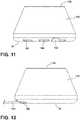
- the handheld appliance 15may also be stored in a case 200, as shown in FIG. 28 .
- the case 200includes a storage compartment 205 with a first slot 210 that is sized and shaped to receive the drive unit 20 and a second slot 215 that is sized and shape to receive the tool 25.
- the case 200also includes a cover 220 for closing the storage compartment 205.
- the handheld appliance as disclosed hereinprovides a single drive unit that is capable of operating multiple types of tools that are capable of a wide variety of tasks.
- the drive unit and the toolscan all be stored together on a base that simultaneously charges the drive unit while the handheld appliance is stored.
- the flexibility of the base to be adjusted to many different configurationsallows the user to fit the base into cabinets or countertop spaces of many shapes and sizes.
Landscapes
- Engineering & Computer Science (AREA)
- Mechanical Engineering (AREA)
- Food Science & Technology (AREA)
- Charge And Discharge Circuits For Batteries Or The Like (AREA)
- Food-Manufacturing Devices (AREA)
Description
- The present invention relates to kitchen appliances. In particular the invention relates to handheld kitchen appliances that are battery operated.
- Handheld kitchen appliances, such as blenders, slicing knifes, cork screws, and can openers have evolved from a purely manual operation, with no assistance from a motor, to an automatic operation with the assistance of a motor. Initially, the motors of these appliances were powered by AC power and required a power cord. However, in recent years many kitchen appliances have been redesigned to be battery operated. Both types of motor operated appliances help automatic kitchen tasks and require less effort by the user. However, the size of the kitchen appliances has increased due to the motor and additional parts. Therefore, these appliances require more space in cabinets or on kitchen counters. Additionally, although the battery operated appliances provide a benefit of being cordless, they require that the batteries be recharged or replaced. This may also require individual charging stations for each appliance, which again requires additional storage space.
- ACCORDING TO ITS ABSTRACT,
US-A-4575255 describes a base for holding a detachable and portable casing to which may be attached a kitchen appliance unit, such as whisk, a spatula, a mixer or the like. These kitchen appliance units fit into receptacles whereat they are accommodated for storage, these units and the portable casing extending vertically upwards from the base. For an operation a unit may be detachably inserted into the portable case which houses a gear train, as well as a motor for driving the same. The portable case, moreover, accommodates a rechargeable battery arrangement for driving the motor. In the portable case, is accommodated one half of a recharging unit consisting of a secondary winding of a transformer and a coil which is encircled thereby. The primary winding and associated core is accommodated in the base. When the portable casing is accommodated in the base, the cores are juxtaposed in coaxial alignment, whereby an alternating current source coupled to the primary winding charges the rechargeable battery arrangement. - Aspects of the present invention are defined by the appended independent claims. Preferred embodiments of the present invention are defined by the appended dependent claims. There is provided a handheld kitchen appliance assembly including a drive unit having a housing, a rechargeable battery disposed within the housing, and a motor disposed within the housing and powered by the battery. The handheld appliance assembly also includes a tool having an attachment portion for releasably connecting the tool to the drive unit. The tool is selectively driven by the drive unit when the tool is connected to the drive unit. A charging unit includes a cavity sized and shaped to receive a portion of the drive unit. The charging unit includes a power supply and is configured to send a charging current to the battery of the drive unit to recharge the battery when the drive unit is received within the cavity. A cradle includes an opening sized and shaped to support the tool when the tool is disconnected from the drive unit. The cradle includes a linkage that is engageable with the charging unit for selectively connecting the cradle to the charging unit.
- Also described herein is a base for supporting a kitchen appliance including a drive unit and a plurality of tools configured to be driven by the drive unit. The drive unit has a rechargeable battery, a motor, and a first electrical contact. The plurality of tools each has a tool element and an attachment portion for releasably connecting the tool to the drive unit. The base includes a charging unit including a cavity sized and shaped to receive a portion of the drive unit to support the drive unit. The cavity includes a second electrical contact, in which the second electrical contact is configured to engage with the first electrical contact of the drive unit when the drive unit is received within the charging unit. A power supply is connected to the charging unit. The power supply is configured to provide power to the charging unit to enable the charging unit to send a charging current to the battery of the drive unit via the first electrical contact and the second electrical contact. The base further includes a plurality of cradles for supporting the plurality of tools. The plurality of cradles each includes an opening sized and shaped to receive one of the plurality of tools.
- Also described herein is a handheld kitchen appliance assembly including a drive unit including a housing having an elongated body with a first end and a second end that is spaced apart from the first end. A rechargeable battery is disposed within the housing, and a motor disposed within the housing and is powered by the battery. An attachment member is positioned on the second end of the housing, and a first electrical contact is positioned on the second end of the housing. The electrical contact is configured to receive a charging current and send the charging current to the battery to recharge the battery. The handheld kitchen appliance further includes a tool including a tool element and an attachment portion. The attachment portion is configured to engage with the attachment member of the drive unit to connect the tool to the drive unit. The handheld kitchen appliance further includes a base including a charging unit having a cavity with a second electrical contact. The cavity is configured to receive the second end of the drive unit so that the first electrical contact of the drive unit engages with the second electrical contact of the charging unit. The second electrical contact is configured to send the charging current to the first electrical contact. The base further includes a cradle having an opening for receiving a portion of the tool. The cradle includes a linkage that is engageable with the charging unit for selectively connecting the cradle to the charging unit.
- The following is also described herein:
A handheld kitchen appliance assembly comprising: - a drive unit including a housing, a rechargeable battery disposed within the housing, and a motor disposed within the housing and powered by the battery;
- a tool including an attachment portion for releasably connecting the tool to the drive unit, the tool selectively driven by the drive unit when the tool is connected to the drive unit;
- a charging unit including a cavity sized and shaped to receive a portion of the drive unit, the charging unit having a power supply and configured to send a charging current to the battery of the drive unit to recharge the battery when the drive unit is received within the cavity; and
- a cradle including an opening sized and shaped to support the tool when the tool is disconnected from the drive unit, the cradle having a linkage engageable with the charging unit for selectively connecting the cradle to the charging unit.
- The charging unit may include a plurality of recesses, each of the recesses sized and shaped to receive the linkage of the cradle. The plurality of recesses may be arranged around a perimeter of the charging unit, and the cradle may be positioned at different angles relative to the charging unit by engaging with different recesses.
- The tool may be one of a plurality of tools. The cradle may be one of a plurality of cradles, the plurality of cradles each including an opening sized and shaped to receive one of the plurality of tools. The linkage of each of the plurality of cradles may be engageable with the charging unit for selectively connecting the respective cradle to the charging unit. The plurality of cradles may be connectable to the charging unit at the same time. The plurality of cradles may each include a recess sized and shaped to receive the linkage of one of the other plurality of cradles.
- The drive unit may include a handgrip and a user interface having a plurality of actuators for controlling the drive unit. The user interface may be positioned proximate the handgrip to enable a user to grasp the handgrip and engage with the user interface using one hand.
- A base for supporting a kitchen appliance including a drive unit and a plurality of tools may be configured to be driven by the drive unit. The drive unit may have a rechargeable battery, a motor, and a first electrical contact. The plurality of tools may each have a tool element and attachment portion for releasably connecting the tool to the drive unit. The base may comprise a charging unit including a cavity sized and shaped to receive a portion of the drive unit to support the drive unit, the cavity including a second electrical contact, the second electrical contact configured to engage with the first electrical contact of the drive unit when the drive unit is received within the charging unit. the base may also comprise a power supply connected to the charging unit, the power supply configured to provide power to the charging unit to enable the charging unit to send a charging current to the battery of the drive unit via the first electrical contact and the second electrical contact. The base may also comprise a plurality of cradles for supporting the plurality of tools, the plurality of cradles each including an opening sized and shaped to receive one of the plurality of tools.
- The charging unit may be configured to support the drive unit in an upright position. At least one of the plurality of cradles may be configured to support at least one of the plurality of tools in an upright position.
- Each of the plurality of cradles may include a linkage engageable with the charging unit for releasably connecting the respective cradle to the charging unit.
- The charging unit may include a plurality of recesses, each of the plurality of recesses sized and shaped to receive the linkage of one of the plurality of cradles. The linkages of the plurality of cradles may be engageable with one of the plurality of recesses.
- Each of the plurality of cradles may include a plurality of recesses sized and shaped to receive the linkage of another one of the plurality of cradles for releasably connecting the plurality of cradles to one another.
- The charging unit may be connectable to more than one of the plurality of cradles at the same time. Each of the plurality of cradles may be connectable to more than one of the plurality of cradles at the same time.
- The charging unit and the plurality of cradles may be configurable in a plurality of different arrangements relative to one another.
- A handheld kitchen appliance assembly, comprising:
- a drive unit including
- a housing having an elongated body with a first end and a second end that is spaced apart from the first end,
- a rechargeable battery disposed within the housing,
- a motor disposed within the housing and powered by the battery,
- an attachment member positioned on the second end of the housing, and
- a first electrical contact positioned on the second end of the housing, the electrical contact configured to receive a charging current and send the charging current to the battery to recharge the battery;
- a tool including a tool element and an attachment portion, the attachment portion configured to engage with the attachment member of the drive unit to connect the tool to the drive unit; and
- a base including
- a charging unit having a cavity with a second electrical contact, the cavity configured to receive the second end of the drive unit so that the first electrical contact of the drive unit engages with the second electrical contact of the charging unit, the second electrical contact configured to send the charging current to the first electrical contact, and
- a cradle having an opening for receiving a portion of the tool, the cradle including a linkage engageable with the charging unit for selectively connecting the cradle to the charging unit.
- The tool may be one of a plurality of tools and the cradle may be one of a plurality of cradles, the plurality of cradles each including an opening sized and shaped to receive one of the plurality of tools.
- Each of the plurality of cradles may further include a linkage engageable with the charging unit for selectively connecting the cradle to the charging unit. The plurality of cradles may be connectable to the charging unit at the same time. Each of the plurality of cradles may include a recess sized and shaped to receive the linkage of one of the other plurality of cradles.
- The charging unit may be configured to support the drive unit in an upright position. At least one of the plurality of cradles may be configured to support at least one of the plurality of tools in an upright position
- Other aspects of the invention will become apparent by consideration of the detailed description and accompanying drawings.
FIG. 1 is a perspective view of an appliance assembly according to one embodiment.FIG. 2 is a front view of the appliance assembly ofFIG. 1 .FIG. 3 is a bottom perspective view of a handheld appliance in a disconnected position.FIG. 4 is a top perspective view of the handheld appliance ofFIG. 3 in a disconnected position.FIG. 5 is a front view of the handheld appliance ofFIG. 3 in a disconnected position.FIG. 6 is a front view of the handheld appliance ofFIG. 3 in a connected position with a plunge blender attachment.FIG. 7 is a front view of the handheld appliance ofFIG. 3 in a connected position with a sauce stirrer attachment.FIG. 8 is a front view of the handheld appliance ofFIG. 3 in a connected position with a whisk attachment.FIG. 9 is a front view of the handheld appliance ofFIG. 3 in a connected position with a salt and pepper mill attachment.FIG. 10 is a perspective view of a charging unit according to one embodiment and a portion of the drive unit.FIG. 11 is a back view of the charging unit ofFIG. 10 .FIG. 12 is a side view of the charging unit ofFIG. 10 .FIG. 13 is a top view of the charging unit ofFIG. 10 .FIG. 14 is a bottom view of the charging unit ofFIG. 10 .FIG. 15 is a perspective view of a cradle according to one embodiment.FIG. 16 is a side view of the cradle ofFIG. 15 .FIG. 17 is a top view of the cradle ofFIG. 15 .FIG. 18 is a bottom view of the cradle ofFIG. 15 .FIG. 19 is a back view of the cradle ofFIG. 15 .FIG. 20 is a front view of the cradle ofFIG. 15 .FIG. 21 is a perspective view of an arrangement of the base according to one embodiment.FIG. 22 is a bottom view of the arrangement of the base according toFIG. 21 .FIG. 23 is a side view of the arrangement of the base according toFIG. 21 .FIG. 24 is an exemplary arrangement of the base.FIG. 25 is an exemplary arrangement of the base.FIG. 26 is an exemplary arrangement of the base.FIG. 27 is an exemplary arrangement of the base.FIG. 28 is a top view of a case for storing the drive unit and the tool.- Before any embodiments of the invention are explained in detail, it is to be understood that the invention is not limited in its application to the details of construction and the arrangement of components set forth in the following description or illustrated in the following drawings. The invention is capable of other embodiments and of being practiced or of being carried out in various ways. Also, it is to be understood that the phraseology and terminology used herein is for the purpose of description and should not be regarded as limiting.
FIGS. 1 and2 illustrate one embodiment of akitchen appliance assembly 10. Thekitchen appliance assembly 10 includes ahandheld appliance 15 having adrive unit 20 and atool 25, and abase 30 for supporting thehandheld appliance 15.FIGS. 3-9 illustrate thehandheld appliance 15 without thebase 30. As shown, thedrive unit 20 and thetool 25 are separate elements that can be selectively connected and disconnected.FIGS. 3-5 show thedrive unit 20 and thetool 25 in a disconnected position, andFIGS. 6-9 show thedrive unit 20 and thetool 25 in a connected position. When thehandheld appliance 15 is not in use, thetool 25 can be detached from thedrive unit 20 and placed on thebase 30 for storage.- Referring to
FIGS. 3-5 , thetool 25 includes a first end forming anattachment portion 35 and a second end having atool element 40. In the illustrated embodiment, theattachment portion 35 and thetool element 40 are spaced apart by arod 45. Theattachment portion 35 includes areceptacle 50 that is sized and shaped to receive a portion of thedrive unit 20 for connecting thetool 25 to thedrive unit 20. Thetool element 40 can be any type of kitchen tool.FIGS. 6-9 illustrate some examples oftool elements 40.FIG. 6 illustrates a plunger blender,FIG. 7 illustrates a sauce stirrer,FIG. 8 illustrates a whisk, andFIG. 9 illustrates a spice mill. Other examples of different kitchen tools include, but are not limited to, slicing knives, knife sharpeners, cork screws, and can openers. In some embodiments, thehandheld appliance 15 includes adrive unit 20 andtools 25, where eachtool 25 includes adifferent tool element 40. In this embodiment, thedrive unit 20 can be connected to any of thetools 25 to drive the operation of thetool 25. Then driveunit 20 is disconnected from onetool 25 and connected to adifferent tool 25 in order to use atool 25 with adifferent tool element 40. - Referring back to
FIGS. 3-5 , thedrive unit 20 includes ahousing 55 that supports a motor (not shown) and a rechargeable battery (not shown) for providing power to the motor. Thehousing 55 is elongated and defines an axis extending between afirst end 60 and asecond end 65 that is spaced apart from thefirst end 60. Ahandgrip 70 is formed on thefirst end 60 of thehousing 55 to enable a user to grasp thedrive unit 20 to operate thehandheld appliance 15. In the illustrated embodiment, thehandgrip 70 has alinear portion 75 and acurved portion 80. Thelinear portion 75 can be grasped by a user's palm with the user's fingers wrapped around thelinear portion 75. Thecurved portion 80 extends above the user's hand to prevent thedrive unit 20 from slipping out of the user's hand during operation. - A
user interface 85 is also disposed on thefirst end 60 of thehousing 55. Theuser interface 85 includes controls 90 (e.g., buttons) for controlling operation of thedrive unit 20. For example, the illustrateduser interface 85 includes a power button 95, a start/stop button 100, and a speed button 105. The power button 95 is used to turn thedrive unit 20 on and to provide power to the motor. The start/stop button 100 is used to actuate thetool 25. The speed button 105 is used for changing speed of thetool 25. In another embodiment, greater or fewer controls 90 may be included in theuser interface 85. In the illustrated embodiment, some of the controls 90 of theuser interface 85 are positioned on thelinear portion 75 of thehandgrip 70 and some of the controls 90 are positioned on thecurved portion 80 of thehandgrip 70. The controls 90 on thelinear portion 75 of thehandgrip 70 can be actuated by a user's fingers while maintaining a grasp on thehandgrip 70. The controls 90 on thecurved portion 80 of thehandgrip 70 can be actuated by a user's thumb while maintaining a grasp on thehandgrip 70. - With continued reference to
FIGS. 3-5 , thesecond end 65 of thedrive unit 20 engages with thetool 25 to connect thetool 25 to thedrive unit 20 and to drive the operation of thetool element 40. Specifically, anattachment member 110 is disposed on thesecond end 65 of thehousing 55 for releasably connecting thetool 25 to thedrive unit 20. Theattachment member 110 enables thetool 25 to be connected and disconnected from thedrive unit 20 without the use of tools. In the illustrated embodiment, theattachment member 110 is a detent that engages with thetool 25. In some embodiments, the detent is spring biased towards a locked position, and a release button is used to move the detent against the spring bias to release thetool 25 from thedrive unit 20. In another embodiment, theattachment member 110 is a threaded connection for screwing thedrive unit 20 and thetool 25 together. In other embodiments, different types quick connect mechanisms known to those skilled in the art can be used to releasably connect thedrive unit 20 and thetool 25. - Once connected to the
drive unit 20 via theattachment member 110, thetool 25 is driven by adrive shaft 115 extending from thesecond end 65 of thedrive unit 20. Thedrive shaft 115 extends along the axis of thehousing 55 in direction away from thehandgrip 70. Thedrive shaft 115 is driven by the motor and engages with thetool 25 to thereby drive the operation of thetool 25. In the illustrated embodiment, when thetool 25 is attached to thedrive unit 20, thetool 25 is fixed with respect to thedrive shaft 115 so that movement of thedrive shaft 115 is transferred to thetool 25. - As shown in
FIGS. 1 and2 , when thehandheld appliance 15 is not in use, a user can disconnect thetool 25 from thedrive unit 20 and place thehandheld appliance 15 on thebase 30 for storage and charging. Thebase 30 includes acharging unit 120 and cradles 125. The chargingunit 120 supports and charges thedrive unit 20 and thecradle 125 supports thetool 25. FIGS. 10-14 illustrate various views of the chargingunit 120. As shown, the chargingunit 120 has a frustoconical shape with an opentop end 130 and a closedbottom end 135. The opentop end 130 forms acavity 140 for receiving thesecond end 65 of thedrive unit 20. Thecavity 140 is sized and shaped to receive thesecond end 65 of thedrive unit 20. For example, in the illustrated embodiment, thecavity 140 is sized and shaped to receive thedrive shaft 115 of thedrive unit 20. The chargingunit 120 supports thedrive unit 20 in an upright position. In other embodiments, the chargingunit 120 may support thedrive unit 20 in other orientations. The chargingunit 120 can be other shapes and sizes that are sufficient to support thedrive unit 20.- In addition, the charging
unit 120 includes apower source 145 and electrical components that are arranged to recharge the battery of thedrive unit 20 when thedrive unit 20 is received within the chargingunit 120. Specifically, the chargingunit 120 includes apower cord 145 that receives AC power and electrical components that convert the AC power to a charging current. An electrical contact 150 is disposed within thecavity 140 of the chargingunit 120 and positioned within thecavity 140 so that the contact 150 aligns with anelectrical contact 155 on thedrive unit 20. When thedrive unit 20 is inserted into the chargingunit 120, thecontact 155 of thedrive unit 20 engages with the contact 150 of the chargingunit 120, which enables the charging current to pass from the chargingunit 120 to thedrive unit 20 to charge the battery. - Referring to
FIG. 14 , the chargingunit 120 also includesrecesses 160 along thebottom end 135 of the chargingunit 120. As will be described in greater detail below, therecesses 160 are used to connect thecradle 125 to thecharging unit 120. Therecesses 160 are arranged around the perimeter of the chargingunit 120, and eachrecess 160 is engageable with thecradle 125. In the illustrated embodiment, the chargingunit 120 includes threerecesses 160. However, in other embodiments, the chargingunit 120 includes greater orfewer recesses 160. FIGS. 15-20 illustrate various views of thecradle 125. Thecradle 125 has a substantially cylindrical shape with an opentop end 165 and a closedbottom end 170. Thetop end 165 forms anopening 175 for receiving thetool 25. Theopening 175 is sized and shaped to receive thetool 25. In some embodiments, theopening 175 is sized and shaped to receive atool 25 with aspecific tool element 40. In other embodiments, theopening 175 is sized and shaped more generally to receive atool 25 with any of thetool elements 40. In other embodiments, thecradle 125 can be other shapes and sizes that are sufficient to support thedrive unit 20.- The
cradle 125 includes alinkage 180 for connecting thecradle 125 to thecharging unit 120. In the illustrated embodiment, thelinkage 180 is atab 185 with ahook 190 at the end of it. Thetab 190 extends from thebottom end 65 of thecradle 125 and extends radially outward to engage with arecess 160 on thecharging unit 120. In other embodiments, thelinkage 180 is another type of coupling member. Therecesses 160 on thecharging unit 120 are sized and shaped to receive thelinkage 180 of thecradle 125. Thelinkages 180 can snap into and out of therecesses 160 to connect and disconnect thecradle 125 from the chargingunit 120. Thelinkage 180 can engage with any of therecesses 160 on thecharging unit 120 in order to adjust thecradle 125 to different angles relative to thecharging unit 120. Furthermore, because thecharging unit 120 includesmultiple recesses 160,multiple cradles 125 can be connected to thecharging unit 120 at the same time. Therefore, when thehandheld appliance 15 includes a plurality oftools 25, eachtool 25 can be supported by adifferent cradle 125. - In addition, each
cradle 125 includesrecesses 195. Therecesses 195 are arranged around the perimeter of thecradle 125. Eachrecess 195 is sized and shaped to receive alinkage 180 of one of theother cradles 125. This enables thecradles 125 to be connected to one another in addition to being connected to thecharging unit 120. Similar to thecharging unit 120, because thecradle 125 includesmultiple recesses 195, thecradle 125 can be connected to multipleother cradles 125 at the same time. Accordingly, thebase 30 can take on different arrangements depending on the number ofcradles 125, and the arrangement and orientation of thecradles 125 and thecharging unit 120. FIGS. 21-27 illustrate some examples of different arrangements of thebase 30. InFIG. 21-23 , thebase 30 includes the chargingunit 120 and threecradles 125. The chargingunit 120 is positioned in the front of thebase 30 and thecradles 125 are connected to thecharging unit 120 in a row. In other words, the first cradle 125a is connected to thecharging unit 120, the second cradle 125b is connected to the first cradle 125a, and the third cradle 125c is connected to the second cradle 125b. The chargingunit 120 and thecradles 125 are oriented in a linear arrangement so that the row is generally straight. Specifically, thelinkages 180 of eachcradle 125 are connected to acentral recess linkages 180 can be connected tonon-central recesses FIGS. 24-27 illustrate the base 30 according to some of the other possible arrangements of the chargingunit 120 and thecradles 125. These arrangements are non-exclusive examples of how to arrange the chargingunits 120 and cradles 125.- In addition to storing the
handheld appliance 15 on thebase 30, thehandheld appliance 15 may also be stored in acase 200, as shown inFIG. 28 . Thecase 200 includes astorage compartment 205 with afirst slot 210 that is sized and shaped to receive thedrive unit 20 and asecond slot 215 that is sized and shape to receive thetool 25. Thecase 200 also includes acover 220 for closing thestorage compartment 205. - The handheld appliance as disclosed herein provides a single drive unit that is capable of operating multiple types of tools that are capable of a wide variety of tasks. In addition, the drive unit and the tools can all be stored together on a base that simultaneously charges the drive unit while the handheld appliance is stored. The flexibility of the base to be adjusted to many different configurations allows the user to fit the base into cabinets or countertop spaces of many shapes and sizes.
Claims (10)
- A handheld kitchen appliance assembly (10) comprising:a drive unit (20) including a housing (55), a rechargeable battery disposed within the housing, and a motor disposed within the housing and powered by the battery;a tool (25) including an attachment portion (35) for releasably connecting the tool to the drive unit, the tool selectively driven by the drive unit when the tool is connected to the drive unit;a charging unit (120) including a cavity (140) sized and shaped to receive a portion of the drive unit, the charging unit having a power supply (145) and configured to send a charging current to the battery of the drive unit to recharge the battery when the drive unit is received within the cavity; anda cradle (125) including an opening (175) sized and shaped to support the tool when the tool is disconnected from the drive unit,characterized by the cradle having a linkage (180) engageable with the charging unit for selectively connecting the cradle to the charging unit.
- The handheld kitchen appliance assembly (10) of claim 1, wherein the charging unit (120) includes a plurality of recesses (160), each of the recesses sized and shaped to receive the linkage of the cradle (125), and preferably wherein the plurality of recesses is arranged around a perimeter of the charging unit, and wherein the cradle can be positioned at different angles relative to the charging unit by engaging with different recesses.
- The handheld kitchen appliance assembly (10) of claim 1, wherein the tool (25) is one of a plurality of tools and the cradle (125) is one of a plurality of cradles, the plurality of cradles each including an opening (175) sized and shaped to receive one of the plurality of tools.
- The handheld kitchen appliance assembly (10) of claim 3, wherein the linkage (180) of each of the plurality of cradles (125) is engageable with the charging unit (120) for selectively connecting the respective cradle to the charging unit, wherein the plurality of cradles are connectable to the charging unit at the same time.
- The handheld kitchen appliance assembly (10) of claim 4, wherein the plurality of cradles (125) each includes a recess (160) sized and shaped to receive the linkage of one of the other plurality of cradles.
- The handheld kitchen appliance assembly (10) of claim 1, wherein the drive unit (20) includes a handgrip (70) and a user interface (85) having a plurality of actuators (90) for controlling the drive unit, the user interface positioned proximate the handgrip to enable a user to grasp the handgrip and engage with the user interface using one hand.
- The handheld kitchen appliance assembly (10) of claim 1,the housing (55) of the drive unit (20) having an elongated body with a first end (60) and a second end (65) that is spaced apart from the first end, and the drive unit further including:an attachment member (110) positioned on the second end of the housing, anda first electrical contact (155) positioned on the second end of the housing, the electrical contact configured to receive a charging current and send the charging current to the battery to recharge the battery;the tool (25) further including a tool element (40), the attachment portion (35) configured to engage with the attachment member of the drive unit to connect the tool to the drive unit; andthe handheld kitchen appliance assembly further comprising a base (30) includingthe charging unit (120), the cavity (140) with a second electrical contact (150), the cavity configured to receive the second end of the drive unit so that the first electrical contact of the drive unit engages with the second electrical contact of the charging unit, the second electrical contact configured to send the charging current to the first electrical contact, andthe cradle (125), the opening (175) for receiving a portion of the tool.
- The handheld kitchen appliance assembly (10) of claim 7, wherein the tool (25) is one of a plurality of tools and the cradle (125) is one of a plurality of cradles, the plurality of cradles each including an opening (175) sized and shaped to receive one of the plurality of tools.
- The handheld kitchen appliance assembly (10) of claim 8, wherein each of the plurality of cradles (125) further includes a linkage (180) engageable with the charging unit (120) for selectively connecting the cradle to the charging unit, wherein the plurality of cradles are connectable to the charging unit at the same time, and preferably wherein each of the plurality of cradles includes a recess (160) sized and shaped to receive the linkage of one of the other plurality of cradles.
- The handheld kitchen appliance assembly (10) of claim 8, wherein the charging unit (120) is configured to support the drive unit (20) in an upright position, and wherein at least one of the plurality of cradles (125) is configured to support at least one of the plurality of tools (25) in an upright position.
Applications Claiming Priority (1)
| Application Number | Priority Date | Filing Date | Title |
|---|---|---|---|
| US15/389,706US10328562B2 (en) | 2016-12-23 | 2016-12-23 | Handheld kitchen appliance assembly |
Publications (2)
| Publication Number | Publication Date |
|---|---|
| EP3338604A1 EP3338604A1 (en) | 2018-06-27 |
| EP3338604B1true EP3338604B1 (en) | 2020-02-19 |
Family
ID=60543409
Family Applications (1)
| Application Number | Title | Priority Date | Filing Date |
|---|---|---|---|
| EP17204725.0AActiveEP3338604B1 (en) | 2016-12-23 | 2017-11-30 | Handheld kitchen appliance assembly |
Country Status (3)
| Country | Link |
|---|---|
| US (1) | US10328562B2 (en) |
| EP (1) | EP3338604B1 (en) |
| CN (1) | CN108236391B (en) |
Cited By (2)
| Publication number | Priority date | Publication date | Assignee | Title |
|---|---|---|---|---|
| US12201242B2 (en) | 2021-02-04 | 2025-01-21 | Black & Decker, Inc. | Modular hand-held kitchen applicance |
| US12262849B2 (en) | 2021-02-04 | 2025-04-01 | Black & Decker, Inc. | Modular hand-held kitchen applicance |
Families Citing this family (16)
| Publication number | Priority date | Publication date | Assignee | Title |
|---|---|---|---|---|
| WO2020118224A1 (en)* | 2018-12-06 | 2020-06-11 | Columbia Insurance Company | Modular appliance apparatus configured for multiple attachments |
| JP6864716B2 (en)* | 2019-07-01 | 2021-04-28 | Hario株式会社 | Grinder unit |
| US12016492B2 (en)* | 2019-10-19 | 2024-06-25 | Alex L Liu | Spice or other substance grinding apparatus with interchangeable substance containers |
| FR3116710B1 (en)* | 2020-12-01 | 2022-11-04 | Seb Sa | HAND-HELD MULTIFUNCTION COOKING APPLIANCE BOX |
| US20220408975A1 (en)* | 2021-02-04 | 2022-12-29 | Black & Decker, Inc. | Food processor and pour spout |
| CN216987814U (en)* | 2022-01-27 | 2022-07-19 | 宁波厨聚厨房科技有限公司 | Small-size machine that grinds |
| US20230276993A1 (en)* | 2022-03-01 | 2023-09-07 | Whirlpool Corporation | Immersion blender |
| US20230292959A1 (en)* | 2022-03-15 | 2023-09-21 | Conair Llc | Handheld food blender with multiple attachments |
| USD1050798S1 (en) | 2022-05-09 | 2024-11-12 | Sharkninja Operating Llc | Mixer base |
| USD1056614S1 (en) | 2022-05-09 | 2025-01-07 | Sharkninja Operating Llc | Hand mixer |
| USD1020365S1 (en) | 2022-05-09 | 2024-04-02 | Sharkninja Operating Llc | Blender attachment |
| USD1050799S1 (en) | 2022-07-08 | 2024-11-12 | Sharkninja Operating Llc | Immersion blender |
| USD1070482S1 (en) | 2022-07-15 | 2025-04-15 | Sharkninja Operating Llc | Hand mixer |
| US20240074618A1 (en)* | 2022-09-06 | 2024-03-07 | Sharkninja Operating Llc | Bottom-driven food processing device attachment and related systems and methods |
| US20250049264A1 (en)* | 2023-08-10 | 2025-02-13 | Whirlpool Corporation | Food processing appliance having an electrical hub connection |
| US12370662B1 (en)* | 2024-05-13 | 2025-07-29 | Hormuzd Chothia | Portable drill attachment |
Family Cites Families (59)
| Publication number | Priority date | Publication date | Assignee | Title |
|---|---|---|---|---|
| US3518523A (en) | 1967-06-12 | 1970-06-30 | Oster Mfg Co John | Control means for blender or the like |
| US3650029A (en) | 1970-05-04 | 1972-03-21 | Mc Graw Edison Co | Electric knife blade securing and safety switch device |
| US4575255A (en)* | 1982-09-07 | 1986-03-11 | Barbara Kafka | Kitchen appliance arrangement with portable unit |
| US4965909A (en) | 1988-10-04 | 1990-10-30 | Mccullough Timothy J | Safety control for power operated equipment |
| US5012582A (en) | 1989-12-15 | 1991-05-07 | Bristol And Williams | Hand-held, battery-operated rotary blade saw |
| EP0735936A1 (en) | 1994-10-21 | 1996-10-09 | Senco Products, Inc | Pneumatic fastener driving tool and an electronic control system therefor |
| CN2265749Y (en)* | 1996-01-29 | 1997-10-29 | 张光升 | Improved structure of hot pot turntable rack |
| US5921658A (en) | 1997-03-25 | 1999-07-13 | Alert Safety Lite Products Co., Inc. | Fluorescent utility light |
| DE19820915A1 (en) | 1998-05-09 | 1999-11-18 | Braun Gmbh | Hand mixer |
| GB9903775D0 (en) | 1999-02-18 | 1999-04-14 | Kenwood Marks Ltd | Tool storage arrangements for domestic appliances |
| US6637925B1 (en) | 1999-09-16 | 2003-10-28 | Seb S.A. | Hand held electrical mixing beater |
| TW437366U (en)* | 1999-12-22 | 2001-05-28 | Huang Li Shuei | Dining ware with electric socket |
| US6181104B1 (en)* | 2000-04-24 | 2001-01-30 | Theodore Rhoads | Rechargeable coffee and spice grinder |
| USD462569S1 (en)* | 2000-09-07 | 2002-09-10 | Man On Metal & Plastic Factory Limited | Milk creamer/mixer with holder |
| DE10133744A1 (en) | 2001-07-11 | 2003-01-30 | Hammelmann Paul Maschf | spray gun |
| US6700340B2 (en) | 2002-03-19 | 2004-03-02 | Hamilton Beach/Proctor-Silex, Inc. | Control circuit for a coffee grinder |
| US6568843B1 (en) | 2002-07-03 | 2003-05-27 | A-Pi Lai | Safety device for a blender |
| AU2002953412A0 (en) | 2002-12-18 | 2003-01-09 | George Stephen Ramsay | Electrical device with a safety switch |
| CN2601611Y (en)* | 2003-02-14 | 2004-02-04 | 梁伟强 | Split induction charging stirrer |
| SE0301890L (en) | 2003-06-26 | 2005-01-25 | Haellde Maskiner Ab | Hand mixer |
| FR2860698B1 (en) | 2003-10-14 | 2005-12-09 | Seb Sa | MIXING FOOT AND MIXER MIXER OF TYPE DIVING PROVIDED WITH SUCH A FOOT OF MIXING. |
| WO2006015403A1 (en)* | 2004-08-09 | 2006-02-16 | Ian Geoffrey Wilson | Cordless mixer |
| DE202004014078U1 (en)* | 2004-09-10 | 2004-11-11 | Wik Far East Ltd. | Cordless electrical apparatus especially for household use such as a milk foamer has battery motor and switch which depends on the position of the device in a charger |
| DE102005038919A1 (en)* | 2005-08-17 | 2007-03-15 | BSH Bosch und Siemens Hausgeräte GmbH | Electric motor kitchen appliance with electrical or electronic interlock |
| DE102005038923A1 (en) | 2005-08-17 | 2007-02-22 | BSH Bosch und Siemens Hausgeräte GmbH | Charging system for a battery operated kitchen appliance |
| DE102005038917A1 (en) | 2005-08-17 | 2007-02-22 | BSH Bosch und Siemens Hausgeräte GmbH | Hand blender with housing shells connected by a clamping cover |
| DE202006020005U1 (en)* | 2005-08-17 | 2007-09-20 | BSH Bosch und Siemens Hausgeräte GmbH | Electric-motor kitchen appliance e.g. handheld-blender, for processing food, has lithium-ion accumulator or lithium-polymer accumulator, and electronic control device controlling charging and discharging of accumulator |
| DE102005038922A1 (en) | 2005-08-17 | 2007-02-22 | BSH Bosch und Siemens Hausgeräte GmbH | Multifunctional holder for a hand blender |
| DE202006011512U1 (en) | 2006-07-24 | 2006-10-12 | Leifheit Ag | Kitchen tool used in the kitchen comprises a handle having an oscillating drive and a coupling unit for coupling a tool to the drive |
| DE102006034643A1 (en) | 2006-07-24 | 2008-01-31 | Leifheit Ag | kitchen appliance |
| FR2910260B1 (en) | 2006-12-22 | 2009-01-23 | Seb Sa | STORAGE BOX FOR MIXING HOUSEHOLD TYPE OF DIVE. |
| US20090303830A1 (en) | 2008-06-06 | 2009-12-10 | Ian Geoffrey Wilson | Hand blender switch |
| DE102008040934A1 (en) | 2008-08-01 | 2010-02-04 | BSH Bosch und Siemens Hausgeräte GmbH | Engine operated kitchen appliance with two buttons for operating the engine at alternative speeds |
| EP2193734A1 (en) | 2008-12-05 | 2010-06-09 | Koninklijke Philips Electronics N.V. | Coupling assembly, kitchen appliance and hand blender |
| CN201879523U (en) | 2010-05-25 | 2011-06-29 | 王�义 | Multifunctional mixer |
| CN102258337A (en) | 2010-05-25 | 2011-11-30 | 王�义 | Multipurpose stirrer |
| EP2394545B1 (en) | 2010-06-09 | 2013-07-17 | BSH Bosch und Siemens Hausgeräte GmbH | Storage container for a hand-held kitchen appliance and accessory |
| DE202011101707U1 (en) | 2010-06-10 | 2011-09-26 | BSH Bosch und Siemens Hausgeräte GmbH | Hand-held kitchen utensil with shaker |
| PL2394544T3 (en) | 2010-06-10 | 2014-10-31 | Bsh Hausgeraete Gmbh | Hand-held kitchen appliance with protective covering |
| ES2689111T3 (en) | 2010-06-10 | 2018-11-08 | BSH Hausgeräte GmbH | Manual kitchen appliance with two drives |
| ES2373176B1 (en) | 2010-06-10 | 2012-12-10 | Electrodomésticos Taurus, S.L. | HANDBAND WITH SEPARABLE HEAD. |
| DE102011082168A1 (en) | 2011-09-06 | 2013-03-07 | BSH Bosch und Siemens Hausgeräte GmbH | Multifunctional kitchen device for use with kitchen blender and impact disk for processing of food at home, has drive device is formed as hand blender drive unit, where hand blender drive unit is connected with one processing tool |
| CN202426373U (en) | 2011-12-26 | 2012-09-12 | 佛山市三水合成电器实业有限公司 | Multifunctional food treatment machine |
| CA2889999C (en) | 2013-02-15 | 2019-10-29 | Babyliss Faco Sprl | Drive unit for electric household appliance parts |
| CN103211525B (en) | 2013-05-09 | 2015-08-19 | 青岛乐康电子有限公司 | A kind of crushing, stirring formula noodle device |
| CN103202666B (en) | 2013-05-09 | 2015-01-28 | 青岛乐康电子有限公司 | Handheld multifunctional food processing device |
| CN203263140U (en) | 2013-05-09 | 2013-11-06 | 青岛乐康电子有限公司 | Multifunctional handheld food processing device |
| CN203341537U (en)* | 2013-06-05 | 2013-12-18 | 深圳市联运贸易发展有限公司 | Rechargeable milk bubbler |
| CN103315650B (en) | 2013-06-27 | 2015-11-18 | 惠阳亚伦塑胶电器实业有限公司 | A kind of double speed handheld blender |
| EP3013199A1 (en) | 2013-06-28 | 2016-05-04 | Koninklijke Philips N.V. | Motor unit, tool unit and hand blender |
| RU2672500C2 (en) | 2013-06-28 | 2018-11-15 | Конинклейке Филипс Н.В. | Hand blender |
| CN203709876U (en) | 2014-03-18 | 2014-07-16 | 惠阳亚伦塑胶电器实业有限公司 | Handheld stirring machine |
| CN203914628U (en)* | 2014-03-31 | 2014-11-05 | 卢明强 | Charging cooking machine |
| CN203953406U (en) | 2014-05-28 | 2014-11-26 | 内蒙古正隆谷物食品有限公司 | A kind of multipurpose domestic mixer |
| CN203914634U (en) | 2014-06-30 | 2014-11-05 | 惠阳亚伦塑胶电器实业有限公司 | A kind of hand-held mixer |
| CN204654712U (en) | 2015-04-21 | 2015-09-23 | 慈溪恒煜电子有限公司 | A kind of universal mixer external member |
| CN204654704U (en) | 2015-04-21 | 2015-09-23 | 慈溪恒煜电子有限公司 | A kind of food preparation suite |
| CN205006701U (en) | 2015-09-30 | 2016-02-03 | 广东科嘉霖电器制造有限公司 | Hand -held type mixer of speed governing and switch integral type device |
| CN205758374U (en)* | 2016-05-09 | 2016-12-07 | 广东金莱特电器股份有限公司 | A kind of Split type stirrer |
- 2016
- 2016-12-23USUS15/389,706patent/US10328562B2/enactiveActive
- 2017
- 2017-11-20CNCN201711159587.0Apatent/CN108236391B/enactiveActive
- 2017-11-30EPEP17204725.0Apatent/EP3338604B1/enactiveActive
Non-Patent Citations (1)
| Title |
|---|
| None* |
Cited By (2)
| Publication number | Priority date | Publication date | Assignee | Title |
|---|---|---|---|---|
| US12201242B2 (en) | 2021-02-04 | 2025-01-21 | Black & Decker, Inc. | Modular hand-held kitchen applicance |
| US12262849B2 (en) | 2021-02-04 | 2025-04-01 | Black & Decker, Inc. | Modular hand-held kitchen applicance |
Also Published As
| Publication number | Publication date |
|---|---|
| US10328562B2 (en) | 2019-06-25 |
| CN108236391B (en) | 2022-04-01 |
| US20180178367A1 (en) | 2018-06-28 |
| CN108236391A (en) | 2018-07-03 |
| EP3338604A1 (en) | 2018-06-27 |
Similar Documents
| Publication | Publication Date | Title |
|---|---|---|
| EP3338604B1 (en) | Handheld kitchen appliance assembly | |
| US12262849B2 (en) | Modular hand-held kitchen applicance | |
| US4575255A (en) | Kitchen appliance arrangement with portable unit | |
| US8757287B2 (en) | Electric-motor kitchen appliance comprising an electric or electronic control | |
| US7932695B2 (en) | Power tool, battery, charger and method of operating the same | |
| EP1791455B1 (en) | Cordless mixer | |
| US20060267556A1 (en) | Power tool, battery, charger and method of operating the same | |
| EP2269490A1 (en) | Domestic appliance with an electronic safety system and a mechanical locking system and method for operating a domestic appliance | |
| EP3838055A1 (en) | Power transmission apparatus and control method therefor, and power supply system | |
| CN106253286A (en) | Power transmission device and its control method, power supply system | |
| US20140230663A1 (en) | Kitchenware Item with a Handle Which Works Electrically with a Removable Accessory | |
| EP1987750A2 (en) | Appliance for warm milk preparation with or without milk froth | |
| US20240090703A1 (en) | Cordless blending appliance | |
| US20110036248A1 (en) | Stand Mixer with Cordless Kitchen Appliance | |
| EP4238461A1 (en) | Hand-held mixer | |
| EP2712713A1 (en) | Electronically driven mobile equipment comprising a battery pack and electronic power supply unit for use with such a mobile equipment | |
| CN107969901B (en) | Heated cooking preparation appliance comprising a steam basket | |
| US6181104B1 (en) | Rechargeable coffee and spice grinder | |
| CN115986869A (en) | Kitchen handheld device, accessory and using method thereof | |
| EP4509449A2 (en) | Electrical appliance | |
| CN112171467B (en) | Electric power tool device | |
| WO2019233860A1 (en) | A blender providing ease of use | |
| US5451123A (en) | Rechargeable portable routing tool | |
| EP3430958A1 (en) | Portable electric rotary slicer | |
| CN219613724U (en) | Kitchen hand-held device and fittings |
Legal Events
| Date | Code | Title | Description |
|---|---|---|---|
| PUAI | Public reference made under article 153(3) epc to a published international application that has entered the european phase | Free format text:ORIGINAL CODE: 0009012 | |
| STAA | Information on the status of an ep patent application or granted ep patent | Free format text:STATUS: THE APPLICATION HAS BEEN PUBLISHED | |
| AK | Designated contracting states | Kind code of ref document:A1 Designated state(s):AL AT BE BG CH CY CZ DE DK EE ES FI FR GB GR HR HU IE IS IT LI LT LU LV MC MK MT NL NO PL PT RO RS SE SI SK SM TR | |
| AX | Request for extension of the european patent | Extension state:BA ME | |
| STAA | Information on the status of an ep patent application or granted ep patent | Free format text:STATUS: REQUEST FOR EXAMINATION WAS MADE | |
| 17P | Request for examination filed | Effective date:20181218 | |
| RBV | Designated contracting states (corrected) | Designated state(s):AL AT BE BG CH CY CZ DE DK EE ES FI FR GB GR HR HU IE IS IT LI LT LU LV MC MK MT NL NO PL PT RO RS SE SI SK SM TR | |
| STAA | Information on the status of an ep patent application or granted ep patent | Free format text:STATUS: EXAMINATION IS IN PROGRESS | |
| 17Q | First examination report despatched | Effective date:20190510 | |
| GRAP | Despatch of communication of intention to grant a patent | Free format text:ORIGINAL CODE: EPIDOSNIGR1 | |
| STAA | Information on the status of an ep patent application or granted ep patent | Free format text:STATUS: GRANT OF PATENT IS INTENDED | |
| INTG | Intention to grant announced | Effective date:20190920 | |
| GRAS | Grant fee paid | Free format text:ORIGINAL CODE: EPIDOSNIGR3 | |
| GRAA | (expected) grant | Free format text:ORIGINAL CODE: 0009210 | |
| STAA | Information on the status of an ep patent application or granted ep patent | Free format text:STATUS: THE PATENT HAS BEEN GRANTED | |
| AK | Designated contracting states | Kind code of ref document:B1 Designated state(s):AL AT BE BG CH CY CZ DE DK EE ES FI FR GB GR HR HU IE IS IT LI LT LU LV MC MK MT NL NO PL PT RO RS SE SI SK SM TR | |
| RAP1 | Party data changed (applicant data changed or rights of an application transferred) | Owner name:TTI (MACAO COMMERCIAL OFFSHORE) LIMITED | |
| REG | Reference to a national code | Ref country code:CH Ref legal event code:EP | |
| REG | Reference to a national code | Ref country code:DE Ref legal event code:R096 Ref document number:602017011931 Country of ref document:DE | |
| REG | Reference to a national code | Ref country code:AT Ref legal event code:REF Ref document number:1233981 Country of ref document:AT Kind code of ref document:T Effective date:20200315 | |
| REG | Reference to a national code | Ref country code:IE Ref legal event code:FG4D | |
| REG | Reference to a national code | Ref country code:NL Ref legal event code:MP Effective date:20200219 | |
| PG25 | Lapsed in a contracting state [announced via postgrant information from national office to epo] | Ref country code:FI Free format text:LAPSE BECAUSE OF FAILURE TO SUBMIT A TRANSLATION OF THE DESCRIPTION OR TO PAY THE FEE WITHIN THE PRESCRIBED TIME-LIMIT Effective date:20200219 Ref country code:RS Free format text:LAPSE BECAUSE OF FAILURE TO SUBMIT A TRANSLATION OF THE DESCRIPTION OR TO PAY THE FEE WITHIN THE PRESCRIBED TIME-LIMIT Effective date:20200219 Ref country code:NO Free format text:LAPSE BECAUSE OF FAILURE TO SUBMIT A TRANSLATION OF THE DESCRIPTION OR TO PAY THE FEE WITHIN THE PRESCRIBED TIME-LIMIT Effective date:20200519 | |
| REG | Reference to a national code | Ref country code:LT Ref legal event code:MG4D | |
| PG25 | Lapsed in a contracting state [announced via postgrant information from national office to epo] | Ref country code:GR Free format text:LAPSE BECAUSE OF FAILURE TO SUBMIT A TRANSLATION OF THE DESCRIPTION OR TO PAY THE FEE WITHIN THE PRESCRIBED TIME-LIMIT Effective date:20200520 Ref country code:HR Free format text:LAPSE BECAUSE OF FAILURE TO SUBMIT A TRANSLATION OF THE DESCRIPTION OR TO PAY THE FEE WITHIN THE PRESCRIBED TIME-LIMIT Effective date:20200219 Ref country code:BG Free format text:LAPSE BECAUSE OF FAILURE TO SUBMIT A TRANSLATION OF THE DESCRIPTION OR TO PAY THE FEE WITHIN THE PRESCRIBED TIME-LIMIT Effective date:20200519 Ref country code:LV Free format text:LAPSE BECAUSE OF FAILURE TO SUBMIT A TRANSLATION OF THE DESCRIPTION OR TO PAY THE FEE WITHIN THE PRESCRIBED TIME-LIMIT Effective date:20200219 Ref country code:SE Free format text:LAPSE BECAUSE OF FAILURE TO SUBMIT A TRANSLATION OF THE DESCRIPTION OR TO PAY THE FEE WITHIN THE PRESCRIBED TIME-LIMIT Effective date:20200219 Ref country code:IS Free format text:LAPSE BECAUSE OF FAILURE TO SUBMIT A TRANSLATION OF THE DESCRIPTION OR TO PAY THE FEE WITHIN THE PRESCRIBED TIME-LIMIT Effective date:20200619 | |
| PG25 | Lapsed in a contracting state [announced via postgrant information from national office to epo] | Ref country code:NL Free format text:LAPSE BECAUSE OF FAILURE TO SUBMIT A TRANSLATION OF THE DESCRIPTION OR TO PAY THE FEE WITHIN THE PRESCRIBED TIME-LIMIT Effective date:20200219 | |
| PG25 | Lapsed in a contracting state [announced via postgrant information from national office to epo] | Ref country code:DK Free format text:LAPSE BECAUSE OF FAILURE TO SUBMIT A TRANSLATION OF THE DESCRIPTION OR TO PAY THE FEE WITHIN THE PRESCRIBED TIME-LIMIT Effective date:20200219 Ref country code:LT Free format text:LAPSE BECAUSE OF FAILURE TO SUBMIT A TRANSLATION OF THE DESCRIPTION OR TO PAY THE FEE WITHIN THE PRESCRIBED TIME-LIMIT Effective date:20200219 Ref country code:PT Free format text:LAPSE BECAUSE OF FAILURE TO SUBMIT A TRANSLATION OF THE DESCRIPTION OR TO PAY THE FEE WITHIN THE PRESCRIBED TIME-LIMIT Effective date:20200712 Ref country code:SM Free format text:LAPSE BECAUSE OF FAILURE TO SUBMIT A TRANSLATION OF THE DESCRIPTION OR TO PAY THE FEE WITHIN THE PRESCRIBED TIME-LIMIT Effective date:20200219 Ref country code:EE Free format text:LAPSE BECAUSE OF FAILURE TO SUBMIT A TRANSLATION OF THE DESCRIPTION OR TO PAY THE FEE WITHIN THE PRESCRIBED TIME-LIMIT Effective date:20200219 Ref country code:CZ Free format text:LAPSE BECAUSE OF FAILURE TO SUBMIT A TRANSLATION OF THE DESCRIPTION OR TO PAY THE FEE WITHIN THE PRESCRIBED TIME-LIMIT Effective date:20200219 Ref country code:SK Free format text:LAPSE BECAUSE OF FAILURE TO SUBMIT A TRANSLATION OF THE DESCRIPTION OR TO PAY THE FEE WITHIN THE PRESCRIBED TIME-LIMIT Effective date:20200219 Ref country code:RO Free format text:LAPSE BECAUSE OF FAILURE TO SUBMIT A TRANSLATION OF THE DESCRIPTION OR TO PAY THE FEE WITHIN THE PRESCRIBED TIME-LIMIT Effective date:20200219 Ref country code:ES Free format text:LAPSE BECAUSE OF FAILURE TO SUBMIT A TRANSLATION OF THE DESCRIPTION OR TO PAY THE FEE WITHIN THE PRESCRIBED TIME-LIMIT Effective date:20200219 | |
| REG | Reference to a national code | Ref country code:AT Ref legal event code:MK05 Ref document number:1233981 Country of ref document:AT Kind code of ref document:T Effective date:20200219 | |
| RAP2 | Party data changed (patent owner data changed or rights of a patent transferred) | Owner name:TTI (MACAO COMMERCIAL OFFSHORE) LIMITED | |
| REG | Reference to a national code | Ref country code:DE Ref legal event code:R097 Ref document number:602017011931 Country of ref document:DE | |
| PLBE | No opposition filed within time limit | Free format text:ORIGINAL CODE: 0009261 | |
| STAA | Information on the status of an ep patent application or granted ep patent | Free format text:STATUS: NO OPPOSITION FILED WITHIN TIME LIMIT | |
| 26N | No opposition filed | Effective date:20201120 | |
| PG25 | Lapsed in a contracting state [announced via postgrant information from national office to epo] | Ref country code:IT Free format text:LAPSE BECAUSE OF FAILURE TO SUBMIT A TRANSLATION OF THE DESCRIPTION OR TO PAY THE FEE WITHIN THE PRESCRIBED TIME-LIMIT Effective date:20200219 Ref country code:AT Free format text:LAPSE BECAUSE OF FAILURE TO SUBMIT A TRANSLATION OF THE DESCRIPTION OR TO PAY THE FEE WITHIN THE PRESCRIBED TIME-LIMIT Effective date:20200219 | |
| PG25 | Lapsed in a contracting state [announced via postgrant information from national office to epo] | Ref country code:SI Free format text:LAPSE BECAUSE OF FAILURE TO SUBMIT A TRANSLATION OF THE DESCRIPTION OR TO PAY THE FEE WITHIN THE PRESCRIBED TIME-LIMIT Effective date:20200219 Ref country code:PL Free format text:LAPSE BECAUSE OF FAILURE TO SUBMIT A TRANSLATION OF THE DESCRIPTION OR TO PAY THE FEE WITHIN THE PRESCRIBED TIME-LIMIT Effective date:20200219 | |
| PG25 | Lapsed in a contracting state [announced via postgrant information from national office to epo] | Ref country code:MC Free format text:LAPSE BECAUSE OF FAILURE TO SUBMIT A TRANSLATION OF THE DESCRIPTION OR TO PAY THE FEE WITHIN THE PRESCRIBED TIME-LIMIT Effective date:20200219 | |
| REG | Reference to a national code | Ref country code:CH Ref legal event code:PL | |
| PG25 | Lapsed in a contracting state [announced via postgrant information from national office to epo] | Ref country code:LU Free format text:LAPSE BECAUSE OF NON-PAYMENT OF DUE FEES Effective date:20201130 | |
| REG | Reference to a national code | Ref country code:BE Ref legal event code:MM Effective date:20201130 | |
| PG25 | Lapsed in a contracting state [announced via postgrant information from national office to epo] | Ref country code:CH Free format text:LAPSE BECAUSE OF NON-PAYMENT OF DUE FEES Effective date:20201130 Ref country code:LI Free format text:LAPSE BECAUSE OF NON-PAYMENT OF DUE FEES Effective date:20201130 | |
| REG | Reference to a national code | Ref country code:IE Ref legal event code:MM4A | |
| PG25 | Lapsed in a contracting state [announced via postgrant information from national office to epo] | Ref country code:IE Free format text:LAPSE BECAUSE OF NON-PAYMENT OF DUE FEES Effective date:20201130 | |
| PG25 | Lapsed in a contracting state [announced via postgrant information from national office to epo] | Ref country code:TR Free format text:LAPSE BECAUSE OF FAILURE TO SUBMIT A TRANSLATION OF THE DESCRIPTION OR TO PAY THE FEE WITHIN THE PRESCRIBED TIME-LIMIT Effective date:20200219 Ref country code:MT Free format text:LAPSE BECAUSE OF FAILURE TO SUBMIT A TRANSLATION OF THE DESCRIPTION OR TO PAY THE FEE WITHIN THE PRESCRIBED TIME-LIMIT Effective date:20200219 Ref country code:CY Free format text:LAPSE BECAUSE OF FAILURE TO SUBMIT A TRANSLATION OF THE DESCRIPTION OR TO PAY THE FEE WITHIN THE PRESCRIBED TIME-LIMIT Effective date:20200219 | |
| PG25 | Lapsed in a contracting state [announced via postgrant information from national office to epo] | Ref country code:MK Free format text:LAPSE BECAUSE OF FAILURE TO SUBMIT A TRANSLATION OF THE DESCRIPTION OR TO PAY THE FEE WITHIN THE PRESCRIBED TIME-LIMIT Effective date:20200219 Ref country code:AL Free format text:LAPSE BECAUSE OF FAILURE TO SUBMIT A TRANSLATION OF THE DESCRIPTION OR TO PAY THE FEE WITHIN THE PRESCRIBED TIME-LIMIT Effective date:20200219 | |
| PG25 | Lapsed in a contracting state [announced via postgrant information from national office to epo] | Ref country code:BE Free format text:LAPSE BECAUSE OF NON-PAYMENT OF DUE FEES Effective date:20201130 | |
| PGFP | Annual fee paid to national office [announced via postgrant information from national office to epo] | Ref country code:DE Payment date:20241127 Year of fee payment:8 | |
| PGFP | Annual fee paid to national office [announced via postgrant information from national office to epo] | Ref country code:GB Payment date:20241127 Year of fee payment:8 | |
| PGFP | Annual fee paid to national office [announced via postgrant information from national office to epo] | Ref country code:FR Payment date:20241128 Year of fee payment:8 |