EP3332704A1 - Real time electroanatomical coloring of the heart - Google Patents
Real time electroanatomical coloring of the heartDownload PDFInfo
- Publication number
- EP3332704A1 EP3332704A1EP17206483.4AEP17206483AEP3332704A1EP 3332704 A1EP3332704 A1EP 3332704A1EP 17206483 AEP17206483 AEP 17206483AEP 3332704 A1EP3332704 A1EP 3332704A1
- Authority
- EP
- European Patent Office
- Prior art keywords
- sensors
- heart
- graphic image
- electrodes
- signals
- Prior art date
- Legal status (The legal status is an assumption and is not a legal conclusion. Google has not performed a legal analysis and makes no representation as to the accuracy of the status listed.)
- Granted
Links
Images


Classifications
- A—HUMAN NECESSITIES
- A61—MEDICAL OR VETERINARY SCIENCE; HYGIENE
- A61B—DIAGNOSIS; SURGERY; IDENTIFICATION
- A61B5/00—Measuring for diagnostic purposes; Identification of persons
- A61B5/24—Detecting, measuring or recording bioelectric or biomagnetic signals of the body or parts thereof
- A61B5/316—Modalities, i.e. specific diagnostic methods
- A61B5/318—Heart-related electrical modalities, e.g. electrocardiography [ECG]
- A—HUMAN NECESSITIES
- A61—MEDICAL OR VETERINARY SCIENCE; HYGIENE
- A61B—DIAGNOSIS; SURGERY; IDENTIFICATION
- A61B5/00—Measuring for diagnostic purposes; Identification of persons
- A61B5/68—Arrangements of detecting, measuring or recording means, e.g. sensors, in relation to patient
- A61B5/6846—Arrangements of detecting, measuring or recording means, e.g. sensors, in relation to patient specially adapted to be brought in contact with an internal body part, i.e. invasive
- A61B5/6847—Arrangements of detecting, measuring or recording means, e.g. sensors, in relation to patient specially adapted to be brought in contact with an internal body part, i.e. invasive mounted on an invasive device
- A61B5/6852—Catheters
- A61B5/6858—Catheters with a distal basket, e.g. expandable basket
- A—HUMAN NECESSITIES
- A61—MEDICAL OR VETERINARY SCIENCE; HYGIENE
- A61B—DIAGNOSIS; SURGERY; IDENTIFICATION
- A61B18/00—Surgical instruments, devices or methods for transferring non-mechanical forms of energy to or from the body
- A61B18/04—Surgical instruments, devices or methods for transferring non-mechanical forms of energy to or from the body by heating
- A61B18/12—Surgical instruments, devices or methods for transferring non-mechanical forms of energy to or from the body by heating by passing a current through the tissue to be heated, e.g. high-frequency current
- A61B18/14—Probes or electrodes therefor
- A61B18/1492—Probes or electrodes therefor having a flexible, catheter-like structure, e.g. for heart ablation
- A—HUMAN NECESSITIES
- A61—MEDICAL OR VETERINARY SCIENCE; HYGIENE
- A61B—DIAGNOSIS; SURGERY; IDENTIFICATION
- A61B5/00—Measuring for diagnostic purposes; Identification of persons
- A61B5/01—Measuring temperature of body parts ; Diagnostic temperature sensing, e.g. for malignant or inflamed tissue
- A—HUMAN NECESSITIES
- A61—MEDICAL OR VETERINARY SCIENCE; HYGIENE
- A61B—DIAGNOSIS; SURGERY; IDENTIFICATION
- A61B5/00—Measuring for diagnostic purposes; Identification of persons
- A61B5/06—Devices, other than using radiation, for detecting or locating foreign bodies ; Determining position of diagnostic devices within or on the body of the patient
- A61B5/065—Determining position of the probe employing exclusively positioning means located on or in the probe, e.g. using position sensors arranged on the probe
- A—HUMAN NECESSITIES
- A61—MEDICAL OR VETERINARY SCIENCE; HYGIENE
- A61B—DIAGNOSIS; SURGERY; IDENTIFICATION
- A61B5/00—Measuring for diagnostic purposes; Identification of persons
- A61B5/24—Detecting, measuring or recording bioelectric or biomagnetic signals of the body or parts thereof
- A61B5/25—Bioelectric electrodes therefor
- A61B5/279—Bioelectric electrodes therefor specially adapted for particular uses
- A61B5/28—Bioelectric electrodes therefor specially adapted for particular uses for electrocardiography [ECG]
- A61B5/283—Invasive
- A61B5/287—Holders for multiple electrodes, e.g. electrode catheters for electrophysiological study [EPS]
- A—HUMAN NECESSITIES
- A61—MEDICAL OR VETERINARY SCIENCE; HYGIENE
- A61B—DIAGNOSIS; SURGERY; IDENTIFICATION
- A61B5/00—Measuring for diagnostic purposes; Identification of persons
- A61B5/24—Detecting, measuring or recording bioelectric or biomagnetic signals of the body or parts thereof
- A61B5/316—Modalities, i.e. specific diagnostic methods
- A61B5/318—Heart-related electrical modalities, e.g. electrocardiography [ECG]
- A61B5/367—Electrophysiological study [EPS], e.g. electrical activation mapping or electro-anatomical mapping
- A—HUMAN NECESSITIES
- A61—MEDICAL OR VETERINARY SCIENCE; HYGIENE
- A61B—DIAGNOSIS; SURGERY; IDENTIFICATION
- A61B5/00—Measuring for diagnostic purposes; Identification of persons
- A61B5/68—Arrangements of detecting, measuring or recording means, e.g. sensors, in relation to patient
- A61B5/6846—Arrangements of detecting, measuring or recording means, e.g. sensors, in relation to patient specially adapted to be brought in contact with an internal body part, i.e. invasive
- A61B5/6847—Arrangements of detecting, measuring or recording means, e.g. sensors, in relation to patient specially adapted to be brought in contact with an internal body part, i.e. invasive mounted on an invasive device
- A61B5/6852—Catheters
- A61B5/6859—Catheters with multiple distal splines
- A—HUMAN NECESSITIES
- A61—MEDICAL OR VETERINARY SCIENCE; HYGIENE
- A61B—DIAGNOSIS; SURGERY; IDENTIFICATION
- A61B5/00—Measuring for diagnostic purposes; Identification of persons
- A61B5/68—Arrangements of detecting, measuring or recording means, e.g. sensors, in relation to patient
- A61B5/6846—Arrangements of detecting, measuring or recording means, e.g. sensors, in relation to patient specially adapted to be brought in contact with an internal body part, i.e. invasive
- A61B5/6867—Arrangements of detecting, measuring or recording means, e.g. sensors, in relation to patient specially adapted to be brought in contact with an internal body part, i.e. invasive specially adapted to be attached or implanted in a specific body part
- A61B5/6869—Heart
- A—HUMAN NECESSITIES
- A61—MEDICAL OR VETERINARY SCIENCE; HYGIENE
- A61B—DIAGNOSIS; SURGERY; IDENTIFICATION
- A61B5/00—Measuring for diagnostic purposes; Identification of persons
- A61B5/74—Details of notification to user or communication with user or patient; User input means
- A61B5/742—Details of notification to user or communication with user or patient; User input means using visual displays
- A61B5/7425—Displaying combinations of multiple images regardless of image source, e.g. displaying a reference anatomical image with a live image
- A—HUMAN NECESSITIES
- A61—MEDICAL OR VETERINARY SCIENCE; HYGIENE
- A61B—DIAGNOSIS; SURGERY; IDENTIFICATION
- A61B5/00—Measuring for diagnostic purposes; Identification of persons
- A61B5/74—Details of notification to user or communication with user or patient; User input means
- A61B5/742—Details of notification to user or communication with user or patient; User input means using visual displays
- A61B5/743—Displaying an image simultaneously with additional graphical information, e.g. symbols, charts, function plots
- G—PHYSICS
- G06—COMPUTING OR CALCULATING; COUNTING
- G06T—IMAGE DATA PROCESSING OR GENERATION, IN GENERAL
- G06T7/00—Image analysis
- G06T7/0002—Inspection of images, e.g. flaw detection
- G06T7/0012—Biomedical image inspection
- A—HUMAN NECESSITIES
- A61—MEDICAL OR VETERINARY SCIENCE; HYGIENE
- A61B—DIAGNOSIS; SURGERY; IDENTIFICATION
- A61B18/00—Surgical instruments, devices or methods for transferring non-mechanical forms of energy to or from the body
- A61B2018/00053—Mechanical features of the instrument of device
- A61B2018/00214—Expandable means emitting energy, e.g. by elements carried thereon
- A61B2018/00267—Expandable means emitting energy, e.g. by elements carried thereon having a basket shaped structure
- A—HUMAN NECESSITIES
- A61—MEDICAL OR VETERINARY SCIENCE; HYGIENE
- A61B—DIAGNOSIS; SURGERY; IDENTIFICATION
- A61B18/00—Surgical instruments, devices or methods for transferring non-mechanical forms of energy to or from the body
- A61B2018/00571—Surgical instruments, devices or methods for transferring non-mechanical forms of energy to or from the body for achieving a particular surgical effect
- A61B2018/00577—Ablation
- A—HUMAN NECESSITIES
- A61—MEDICAL OR VETERINARY SCIENCE; HYGIENE
- A61B—DIAGNOSIS; SURGERY; IDENTIFICATION
- A61B18/00—Surgical instruments, devices or methods for transferring non-mechanical forms of energy to or from the body
- A61B2018/00636—Sensing and controlling the application of energy
- A61B2018/0066—Sensing and controlling the application of energy without feedback, i.e. open loop control
- A—HUMAN NECESSITIES
- A61—MEDICAL OR VETERINARY SCIENCE; HYGIENE
- A61B—DIAGNOSIS; SURGERY; IDENTIFICATION
- A61B18/00—Surgical instruments, devices or methods for transferring non-mechanical forms of energy to or from the body
- A61B2018/00636—Sensing and controlling the application of energy
- A61B2018/00696—Controlled or regulated parameters
- A61B2018/00702—Power or energy
- A—HUMAN NECESSITIES
- A61—MEDICAL OR VETERINARY SCIENCE; HYGIENE
- A61B—DIAGNOSIS; SURGERY; IDENTIFICATION
- A61B18/00—Surgical instruments, devices or methods for transferring non-mechanical forms of energy to or from the body
- A61B2018/00636—Sensing and controlling the application of energy
- A61B2018/00773—Sensed parameters
- A61B2018/00791—Temperature
- A—HUMAN NECESSITIES
- A61—MEDICAL OR VETERINARY SCIENCE; HYGIENE
- A61B—DIAGNOSIS; SURGERY; IDENTIFICATION
- A61B18/00—Surgical instruments, devices or methods for transferring non-mechanical forms of energy to or from the body
- A61B2018/00636—Sensing and controlling the application of energy
- A61B2018/00773—Sensed parameters
- A61B2018/00839—Bioelectrical parameters, e.g. ECG, EEG
- A—HUMAN NECESSITIES
- A61—MEDICAL OR VETERINARY SCIENCE; HYGIENE
- A61B—DIAGNOSIS; SURGERY; IDENTIFICATION
- A61B18/00—Surgical instruments, devices or methods for transferring non-mechanical forms of energy to or from the body
- A61B2018/00636—Sensing and controlling the application of energy
- A61B2018/00773—Sensed parameters
- A61B2018/00875—Resistance or impedance
- A—HUMAN NECESSITIES
- A61—MEDICAL OR VETERINARY SCIENCE; HYGIENE
- A61B—DIAGNOSIS; SURGERY; IDENTIFICATION
- A61B18/00—Surgical instruments, devices or methods for transferring non-mechanical forms of energy to or from the body
- A61B2018/00636—Sensing and controlling the application of energy
- A61B2018/00773—Sensed parameters
- A61B2018/00892—Voltage
- A—HUMAN NECESSITIES
- A61—MEDICAL OR VETERINARY SCIENCE; HYGIENE
- A61B—DIAGNOSIS; SURGERY; IDENTIFICATION
- A61B18/00—Surgical instruments, devices or methods for transferring non-mechanical forms of energy to or from the body
- A61B18/04—Surgical instruments, devices or methods for transferring non-mechanical forms of energy to or from the body by heating
- A61B18/12—Surgical instruments, devices or methods for transferring non-mechanical forms of energy to or from the body by heating by passing a current through the tissue to be heated, e.g. high-frequency current
- A61B18/14—Probes or electrodes therefor
- A61B2018/1405—Electrodes having a specific shape
- A61B2018/1435—Spiral
- A—HUMAN NECESSITIES
- A61—MEDICAL OR VETERINARY SCIENCE; HYGIENE
- A61B—DIAGNOSIS; SURGERY; IDENTIFICATION
- A61B2505/00—Evaluating, monitoring or diagnosing in the context of a particular type of medical care
- A61B2505/05—Surgical care
- A—HUMAN NECESSITIES
- A61—MEDICAL OR VETERINARY SCIENCE; HYGIENE
- A61B—DIAGNOSIS; SURGERY; IDENTIFICATION
- A61B2562/00—Details of sensors; Constructional details of sensor housings or probes; Accessories for sensors
- A61B2562/02—Details of sensors specially adapted for in-vivo measurements
- A61B2562/0257—Proximity sensors
- A—HUMAN NECESSITIES
- A61—MEDICAL OR VETERINARY SCIENCE; HYGIENE
- A61B—DIAGNOSIS; SURGERY; IDENTIFICATION
- A61B2562/00—Details of sensors; Constructional details of sensor housings or probes; Accessories for sensors
- A61B2562/02—Details of sensors specially adapted for in-vivo measurements
- A61B2562/0271—Thermal or temperature sensors
- A—HUMAN NECESSITIES
- A61—MEDICAL OR VETERINARY SCIENCE; HYGIENE
- A61B—DIAGNOSIS; SURGERY; IDENTIFICATION
- A61B2576/00—Medical imaging apparatus involving image processing or analysis
- A61B2576/02—Medical imaging apparatus involving image processing or analysis specially adapted for a particular organ or body part
- A61B2576/023—Medical imaging apparatus involving image processing or analysis specially adapted for a particular organ or body part for the heart
- A—HUMAN NECESSITIES
- A61—MEDICAL OR VETERINARY SCIENCE; HYGIENE
- A61B—DIAGNOSIS; SURGERY; IDENTIFICATION
- A61B5/00—Measuring for diagnostic purposes; Identification of persons
- A61B5/48—Other medical applications
- A61B5/4848—Monitoring or testing the effects of treatment, e.g. of medication
- A—HUMAN NECESSITIES
- A61—MEDICAL OR VETERINARY SCIENCE; HYGIENE
- A61B—DIAGNOSIS; SURGERY; IDENTIFICATION
- A61B5/00—Measuring for diagnostic purposes; Identification of persons
- A61B5/72—Signal processing specially adapted for physiological signals or for diagnostic purposes
- A61B5/7271—Specific aspects of physiological measurement analysis
- A61B5/7285—Specific aspects of physiological measurement analysis for synchronizing or triggering a physiological measurement or image acquisition with a physiological event or waveform, e.g. an ECG signal
- G—PHYSICS
- G06—COMPUTING OR CALCULATING; COUNTING
- G06T—IMAGE DATA PROCESSING OR GENERATION, IN GENERAL
- G06T2207/00—Indexing scheme for image analysis or image enhancement
- G06T2207/30—Subject of image; Context of image processing
- G06T2207/30004—Biomedical image processing
- G06T2207/30048—Heart; Cardiac
- G—PHYSICS
- G16—INFORMATION AND COMMUNICATION TECHNOLOGY [ICT] SPECIALLY ADAPTED FOR SPECIFIC APPLICATION FIELDS
- G16H—HEALTHCARE INFORMATICS, i.e. INFORMATION AND COMMUNICATION TECHNOLOGY [ICT] SPECIALLY ADAPTED FOR THE HANDLING OR PROCESSING OF MEDICAL OR HEALTHCARE DATA
- G16H30/00—ICT specially adapted for the handling or processing of medical images
- G16H30/40—ICT specially adapted for the handling or processing of medical images for processing medical images, e.g. editing
Definitions
- This inventionrelates to measurement of bioelectric currents. More particularly, this invention relates to systems for recording bioelectric signals from the heart using means inserted into the body.
- Mapping of electrical potentials in the heartis now commonly performed, using cardiac catheters comprising electrophysiological sensors for mapping the electrical activity of the heart.
- time-varying electrical potentials in the endocardiumare sensed and recorded as a function of position inside the heart, and then used to map a local activation time.
- Activation timediffers from point to point in the endocardium due to the time required for conduction of electrical impulses through the heart muscle.
- the direction of this electrical conduction at any point in the heartis conventionally represented by an activation vector, which is normal to an isoelectric activation front, both of which may be derived from a map of activation time.
- the rate of propagation of the activation front through any point in the endocardiummay be represented as a velocity vector.
- Mapping the activation front and conduction fieldsaids the physician in identifying and diagnosing abnormalities, such as ventricular and atrial tachycardia and ventricular and atrial fibrillation, which result from areas of impaired electrical propagation in the heart tissue.
- Localized defects in the heart's conduction of activation signalsmay be identified by observing phenomena such as multiple activation fronts, abnormal concentrations of activation vectors, or changes in the velocity vector or deviation of the vector from normal values. Examples of such defects include re-entrant areas, which may be associated with signal patterns known as complex fractionated electrograms. Once a defect is located by such mapping, it may be ablated (if it is functioning abnormally) or otherwise treated to restore the normal function of the heart insofar as is possible.
- Mapping of the electrical activation time in the heart musclerequires that the location of the sensor within the heart be known at the time of each measurement.
- mappingwas performed using a single movable electrode sensor inside the heart, which sensor measured activation time relative to a fixed external reference electrode. This technique, however, requires calibration, for example impedance calibrations with adjustments for impedance unrelated to that of the body.
- Mapping of electrical activation time using a single electrodewas, furthermore, a lengthy procedure, generally performed under fluoroscopic imaging, and thereby exposing the patient to undesirable ionizing radiation.
- activation times at a single locationmay change between consecutive beats.
- Electrogramsmay be measured by unipolar or bipolar leads, and are used, e.g., to determine onset of electrical propagation at a point, known as local activation time.
- a map that is initially monocolored, e.g., gray,is presented and colored. Periodically the coloring is removed, and the map recolored based on updated information.
- the userselects regions of the map using any catheters being used. These regions are colored in real time according to the value of a parameter to present a functional display.
- the parameter represented by the coloringcan be selected by the user, e.g., unipolar potentials, bipolar potentials, or local activation times.
- a method of catheterizationwhich is carried out by inserting a probe into a heart of a living subject, the distal portion of the probe having a plurality of sensors disposed thereon.
- the methodis further carried out iteratively by displaying the heart as a first graphic image, processing signals from the sensors according to a predefined algorithm to generate respective outputs, selecting a region on the first graphic image that is less than all of the first graphic image, graphically displaying at least a portion of the outputs on the selected region as a second graphic image, and thereafter removing the second graphic image.
- the sensorsare electrodes and the signals are bioelectric voltages.
- the predefined algorithmincludes a calculation of wavefront propagation and the outputs are local activation times at respective locations of the sensors.
- the sensorsare temperature sensors.
- the sensorsare contact force sensors.
- the sensorsare location sensors.
- removing the second graphic imageis performed after elapse of a time interval.
- One aspect of the methodincludes gating signals from the sensors according to a cardiorespiratory cycle.
- an apparatusincluding a probe having a plurality of electrodes and sensors, electrical circuitry for receiving data from the electrodes and sensors when the probe is at a location in a heart of a living subject, a memory, a display monitor, and a processor connected to the memory and the display monitor.
- the apparatusis operative for iteratively displaying the heart as a first graphic image, processing signals from the sensors according to a predefined algorithm to generate respective outputs, selecting a region on the first graphic image that is less than all of the first graphic image, graphically displaying at least a portion of the outputs on the selected region as a second graphic image, and thereafter removing the second graphic image.
- the apparatusmay include gating circuitry linked to signals from the sensors, the gating circuitry operative for gating the sensor outputs according to the cardiorespiratory cycle.
- Fig. 1is a pictorial illustration of a system 10 for evaluating electrical activity in a heart of a living subject, which is constructed and operative in accordance with a disclosed embodiment of the invention.
- the systemcomprises a catheter 14, which is percutaneously inserted by an operator 16 through the patient's vascular system into a chamber or vascular structure of a heart 12.
- the operator 16who is typically a physician, brings the catheter's distal tip 18 into contact with the heart wall, for example, at an ablation target site.
- Electrical activation mapsmay be prepared, according to the methods disclosed in U.S. Patent Nos. 6,226,542 , and 6,301,496 , and in commonly assigned U.S. Patent No. 6,892,091 , whose disclosures are herein incorporated by reference.
- the system 10may comprise a general purpose or embedded computer processor, which is programmed with suitable software for carrying out the functions described hereinbelow.
- portions of the system 10 shown in other drawing figures hereinare shown as comprising a number of separate functional blocks, these blocks are not necessarily separate physical entities, but rather may represent, for example, different computing tasks or data objects stored in a memory that is accessible to the processor. These tasks may be carried out in software running on a single processor, or on multiple processors.
- the softwaremay be provided to the processor or processors on tangible non-transitory media, such as CD-ROM or non-volatile memory.
- the system 10may comprise a digital signal processor or hard-wired logic.
- CARTO® 3 Systemavailable from 30 Biosense Webster, Inc., 3333 Diamond Canyon Road, Diamond Bar, CA 91765 .
- This systemmay be modified by those skilled in the art to embody the principles of the invention described herein.
- Areas determined to be abnormalcan be ablated by application of thermal energy, e.g., by passage of radiofrequency electrical current through wires in the catheter to one or more electrodes at the distal tip 18, which apply the radiofrequency energy to the myocardium.
- the energyis absorbed in the tissue, heating it to a point (typically about 50°C) at which it permanently loses its electrical excitability.
- this procedurecreates non-conducting lesions in the cardiac tissue, which disrupt the abnormal electrical pathway causing the arrhythmia.
- the principles of the inventioncan be applied to different heart chambers to diagnose and treat many different cardiac arrhythmias.
- the catheter 14typically comprises a handle 20, having suitable controls on the handle to enable the operator 16 to steer, position and orient the distal end of the catheter as desired for the ablation.
- the distal portion of the catheter 14contains position sensors (not shown) that provide signals to a processor 22, located in a console 24.
- the processor 22may fulfill several processing functions as described below.
- the catheter 14is a multi-electrode catheter, which can be a basket catheter as shown in the right portion of balloon 37, or a spline catheter as shown in the left portion.
- multiple electrodes 32which are used as sensing electrodes and have known locations on the basket or spline, and known relationships to one another.
- the catheteris located in the heart, for example by constructing a current position map, the location of each of the electrodes 32 in the heart is known.
- One method for generation of a current position mapis described in commonly assigned U.S. Patent No. 8,478,383 to Bar-Tal et al. , which is herein incorporated by reference.
- Electrodes 32located at or near the distal tip 18 of the catheter 14 via cable 34 to the console 24.
- Pacing signals and other control signalsmay be conveyed from the console 24 through the cable 34 and the electrodes 32 to the heart 12.
- Wire connections 35link the console 24 with body surface electrodes 30 and other components of a positioning sub-system for measuring location and orientation coordinates of the catheter 14.
- the processor 22 or another processormay be an element of the positioning subsystem.
- the electrodes 32 and the body surface electrodes 30may be used to measure tissue impedance at the ablation site as taught in U.S. Patent No. 7,536,218, issued to Govari et al. , which is herein incorporated by reference.
- a sensor for obtaining a physiological parametersuch as an electrode or temperature sensor (not shown), typically a thermocouple or thermistor, may be mounted near the distal tip 18 of the catheter 14.
- the console 24typically contains one or more ablation power generators 25.
- the catheter 14may be adapted to conduct ablative energy to the heart using any known ablation technique, e.g., radiofrequency energy, ultrasound energy, and laser-produced light energy. Such methods are disclosed in commonly assigned U.S. Patent Nos. 6,814,733 , 6,997,924 , and 7,156,816 , which are herein incorporated by reference.
- the positioning subsystemcomprises a magnetic position tracking arrangement that determines the position and orientation of the catheter 14 by generating magnetic fields in a predefined working volume and sensing these fields at the catheter, using field generating coils 28.
- a suitable positioning subsystemis described in U.S. Patent No. 7,756,576 , which is hereby incorporated by reference, and in the above-noted U.S. Patent No. 7,536,218 .
- Console 24includes a processor, preferably a computer with appropriate signal processing circuits, which may include gating circuitry that can be configured for gating sensor readings according to the cardiorespiratory cycle.
- the processoris coupled to drive a monitor 29.
- the signal processing circuitstypically receive, amplify, filter and digitize signals from the catheter 14, including signals generated by the above-noted sensors and a plurality of location sensing electrodes (not shown) located distally in the catheter 14. The digitized signals are received and used by the console 24 and the positioning system to compute the position and orientation of the catheter 14 and to analyze the electrical signals from the electrodes as described in further detail below.
- the system 10includes other elements, which are not shown in the figures for the sake of simplicity.
- the system 10may include an electrocardiogram (ECG) monitor, coupled to receive signals from one or more body surface electrodes, to provide an ECG synchronization signal to the console 24.
- ECGelectrocardiogram
- the system 10typically also includes a reference position sensor, either on an externally applied reference patch attached to the exterior of the subject's body, or on an internally-placed catheter, which is inserted into the heart 12 and maintained in a fixed position relative to the heart 12.
- the system 10may receive image data from an external imaging modality, such as an MRI unit or the like and includes image processors that can be incorporated in or invoked by the processor 22 for generating and displaying images that are described below.
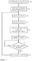
- Fig. 2is a flow chart of a method for real-time coloring of an electrophysiological map of the heart in accordance with an embodiment of the invention.
- the process stepsare shown in a particular linear sequence in Fig. 2 for clarity of presentation. However, it will be evident that many of them can be performed in parallel, asynchronously, or in different orders.
- a processcould alternatively be represented as a number of interrelated states or events, e.g., in a state diagram.
- not all illustrated process stepsmay be required to implement the process.
- one or more cardiac cathetersare introduced into the heart of a subject using well-known methods.
- a reconstruction of the structure of the heart or the chamberis prepared, i.e., geometrically defined in 3-dimensional space.
- Thiscan be accomplished by analysis of images from other modalities, i.e., segmentation from pre-acquired magnetic resonance images or fluoroscopy images that have been registered with model of the chamber. Registration of images acquired or prepared by different modalities is known, for example from U.S. Patent Application Publication No. 2007/0049817 , and commonly assigned U.S. Patent No. 7,517,318 to Altmann et al. , which are herein incorporated by reference. Yet another method of generating the reconstruction is disclosed in commonly assigned U.S. Patent No. 9,265,434 to Merschon et al.
- the atrium shapeis represented as the isosurface of a field function, defined at all points within a bounding domain
- Other methods of reconstructionare known in the art and may be used, for example the methods disclosed in U.S. Patent No. 6,226,542 to Reisfeld , and U.S. Patent Application Publication No. 2009/0177089 by Govari et al. , which are commonly assigned herewith and incorporated by reference.
- the CARTOMERGETM module and other facilities of the above-noted CARTO systemcan accomplish this step using images of the heart prepared at the same or a different session.
- step 41the reconstruction is displayed in a single color or shade, without contrast.
- the representationconveys no functional electroanatomic information, but simply depicts a model of the structure of the subject's heart.
- the sensorsmay be a selected group of electrodes on a multielectrode catheter, for example electrodes on a spline, or a set of electrodes known to be in contact with the endocardium.
- the sensorscan be, for example, location sensors that are components of the above-described positioning system ( Fig. 1 ), mapping electrodes, or sensors of physical states such as temperature, voltages and electrical phase information, contact force, or a combination thereof.
- step 45data is accumulated over a time interval and processed according to some algorithm in order to develop a functional electroanatomic map. For example, voltages may be accumulated over a cardiac cycle to derive spatial LAT's.
- the second derivative of reflectance datamay be displayed, as described in commonly assigned U.S. Patent Application Publication No. 20150305812 by Govari et al. , entitled Prevention of Steam Pops during Ablation, which is herein incorporated by reference.
- the values of the information measured or derivedmay be conveniently shown on the monitor 29 in pseudocolors representing ranges of values.
- the informationmay be gated to the cardiorespiratory cycle and could be unipolar or bipolar potentials.
- a region of 3-dimensional space of the cardiac reconstruction prepared in step 41is selected for display.
- the regionis automatically created based on current locations of sensors on the catheter, and the display spatially indicates information derived from readings of the sensors.
- the radius influenced at the locations, and thus the size of the displayed regionis user-definable.
- the information in the regional displaymay be represented in the as pseudocolors as known in the art, or may be shown in any other suitable graphic display Nonselected areas remain in monocolor. As creating and updating the display is limited to an area of interest, the algorithm may execute more rapidly, sparing computer resources, as it is not necessary to redraw a functional map of the entire heart. Moreover, the operator is protected from information overload.
- step 49after reading data from the sensors and processing the data as required in step 45, the output values are displayed in pseudocolor only on the region chosen in step 47.
- Processing the datacan be, for example, a calculation of wavefront propagation and the output values can be local activation times at respective locations of the sensors.
- controlproceeds to a delay step 51, where an event leading to regeneration of the display of step 49 is awaited.
- the eventmay be elapse of a predefined time interval.
- step 53the display of step 49 is erased, transiently resulting in the reappearance of a monocolored image on the monitor 29, depending on the system performance.
- Controlthen returns to step 43 to iterate the display process, using new readings of the sensors.
- a different regionmay be selected in step 47, particularly if the catheter has been navigated in the heart since the previous iteration.
- the regional displayis deleted and updated with new data every 16 ms, or once during each gating interval, according to the current mode of operation.
- FIG. 3is a screen display 55 that was produced during a cardiac catheterization in accordance with an embodiment of the invention.
- a reconstruction 57 of the left atrium of the heartis shown as a mostly monocolored grey form.
- Catheters 59, 61have been inserted into the heart.
- Catheter 61is an ablation catheter whose distal end lies in a pulmonary vein ostium.
- Colored area 63 near the tip of the catheterrepresents temperature at an ablation site in the ostium.
- Catheter 59is a lasso catheter having multiple mapping electrodes 67.
- a colored area 65 about some of the electrodes 67is a map of local activation time in the region, which may vary as the ablation proceeds. Colored areas 63, 65 are represented by different hatching patterns in the figure.
- Fig. 4is another screen display 69 similar to Fig. 3 taken at another time during the catheterization in accordance with an embodiment of the invention.
- the reconstruction 57has been rotated in order to better display certain areas of interest.
- the parameter represented by area 65has changed, as indicated by differences in coloration compared to Fig. 3 .
Landscapes
- Health & Medical Sciences (AREA)
- Life Sciences & Earth Sciences (AREA)
- Engineering & Computer Science (AREA)
- General Health & Medical Sciences (AREA)
- Physics & Mathematics (AREA)
- Medical Informatics (AREA)
- Surgery (AREA)
- Veterinary Medicine (AREA)
- Biomedical Technology (AREA)
- Heart & Thoracic Surgery (AREA)
- Molecular Biology (AREA)
- Animal Behavior & Ethology (AREA)
- Public Health (AREA)
- Pathology (AREA)
- Biophysics (AREA)
- Nuclear Medicine, Radiotherapy & Molecular Imaging (AREA)
- Radiology & Medical Imaging (AREA)
- Cardiology (AREA)
- Physiology (AREA)
- Computer Vision & Pattern Recognition (AREA)
- Human Computer Interaction (AREA)
- General Physics & Mathematics (AREA)
- Theoretical Computer Science (AREA)
- Quality & Reliability (AREA)
- Plasma & Fusion (AREA)
- Otolaryngology (AREA)
- Signal Processing (AREA)
- Artificial Intelligence (AREA)
- Psychiatry (AREA)
- Measurement And Recording Of Electrical Phenomena And Electrical Characteristics Of The Living Body (AREA)
- Surgical Instruments (AREA)
- Materials For Medical Uses (AREA)
- Dental Preparations (AREA)
Abstract
Description
- A portion of the disclosure of this patent document contains material that is subject to copyright protection. The copyright owner has no objection to the facsimile reproduction by anyone of the patent document or the patent disclosure, as it appears in the Patent and Trademark Office patent file or records, but otherwise reserves all copyright rights whatsoever.
- This invention relates to measurement of bioelectric currents. More particularly, this invention relates to systems for recording bioelectric signals from the heart using means inserted into the body.
- Mapping of electrical potentials in the heart is now commonly performed, using cardiac catheters comprising electrophysiological sensors for mapping the electrical activity of the heart. Typically, time-varying electrical potentials in the endocardium are sensed and recorded as a function of position inside the heart, and then used to map a local activation time. Activation time differs from point to point in the endocardium due to the time required for conduction of electrical impulses through the heart muscle. The direction of this electrical conduction at any point in the heart is conventionally represented by an activation vector, which is normal to an isoelectric activation front, both of which may be derived from a map of activation time. The rate of propagation of the activation front through any point in the endocardium may be represented as a velocity vector.
- Mapping the activation front and conduction fields aids the physician in identifying and diagnosing abnormalities, such as ventricular and atrial tachycardia and ventricular and atrial fibrillation, which result from areas of impaired electrical propagation in the heart tissue.
- Localized defects in the heart's conduction of activation signals may be identified by observing phenomena such as multiple activation fronts, abnormal concentrations of activation vectors, or changes in the velocity vector or deviation of the vector from normal values. Examples of such defects include re-entrant areas, which may be associated with signal patterns known as complex fractionated electrograms. Once a defect is located by such mapping, it may be ablated (if it is functioning abnormally) or otherwise treated to restore the normal function of the heart insofar as is possible.
- Mapping of the electrical activation time in the heart muscle requires that the location of the sensor within the heart be known at the time of each measurement. In the past, such mapping was performed using a single movable electrode sensor inside the heart, which sensor measured activation time relative to a fixed external reference electrode. This technique, however, requires calibration, for example impedance calibrations with adjustments for impedance unrelated to that of the body. Mapping of electrical activation time using a single electrode was, furthermore, a lengthy procedure, generally performed under fluoroscopic imaging, and thereby exposing the patient to undesirable ionizing radiation. Furthermore, in an arrhythmic heart, activation times at a single location may change between consecutive beats.
- Because of the drawbacks of single-electrode mapping, a number of inventors have taught the use of multiple electrodes to measure electrical potentials simultaneously at different locations in the endocardium, thereby allowing activation time to be mapped more rapidly and conveniently, as described. Catheters containing position sensors may be used to determine the trajectory of points on the cardiac surface. These trajectories may be used to infer motion characteristics such as the contractility of the tissue. As disclosed in
U.S. Patent No. 5,738,096 , issued to Ben Haim, which is incorporated herein in its entirety by reference, maps depicting such motion characteristics may be constructed when the trajectory information is sampled at a sufficient number of points in the heart. - Electrical activity at a point in the heart is typically measured by advancing a multiple-electrode catheter to measure electrical activity at multiple points in the heart chamber simultaneously. A record derived from time varying electrical potentials as measured by one or more electrodes is known as an electrogram. Electrograms may be measured by unipolar or bipolar leads, and are used, e.g., to determine onset of electrical propagation at a point, known as local activation time.
- Commonly assigned
U.S. Patent Application Publication No. 20160120427 by Zino et al. , whose disclosure is herein incorporated by reference, describes near realtime data display of electroanatomic data obtained from the heart on a monitor. During a time interval that does not exceed a duration of a cardiac cycle of the heart the following steps are performed: reading data from at least one of the electrodes and sensors, and invoking a processor to perform an algorithm on the data. The data is one of a plurality of inputs of the algorithm, and the result of the algorithm includes a transformation of the data. The result of the algorithm is rendered on the monitor to modify an electroanatomical map. - In a conventional cardiac catheterization procedure a colored electroanatomic map is stable until the user starts to ablate. Once the user has begun ablation, the electroanatomical behavior of the heart changes, but the displayed map remains the same. To see the results of the ablation, the user needs to create a new map and recolor it. This takes time and effort.
- .According to disclosed embodiments of the invention, in one mode of operation a map that is initially monocolored, e.g., gray, is presented and colored. Periodically the coloring is removed, and the map recolored based on updated information. The user selects regions of the map using any catheters being used. These regions are colored in real time according to the value of a parameter to present a functional display. The parameter represented by the coloring can be selected by the user, e.g., unipolar potentials, bipolar potentials, or local activation times.
- There is provided according to embodiments of the invention a method of catheterization, which is carried out by inserting a probe into a heart of a living subject, the distal portion of the probe having a plurality of sensors disposed thereon. The method is further carried out iteratively by displaying the heart as a first graphic image, processing signals from the sensors according to a predefined algorithm to generate respective outputs, selecting a region on the first graphic image that is less than all of the first graphic image, graphically displaying at least a portion of the outputs on the selected region as a second graphic image, and thereafter removing the second graphic image.
- According to one aspect of the method, the sensors are electrodes and the signals are bioelectric voltages.
- According to a further aspect of the method, the predefined algorithm includes a calculation of wavefront propagation and the outputs are local activation times at respective locations of the sensors.
- According to yet another aspect of the method, the sensors are temperature sensors.
- According to still another aspect of the method, the sensors are contact force sensors.
- According to another aspect of the method, the sensors are location sensors.
- According to an additional aspect of the method, removing the second graphic image is performed after elapse of a time interval.
- One aspect of the method includes gating signals from the sensors according to a cardiorespiratory cycle.
- There is further provided according to embodiments of the invention an apparatus, including a probe having a plurality of electrodes and sensors, electrical circuitry for receiving data from the electrodes and sensors when the probe is at a location in a heart of a living subject, a memory, a display monitor, and a processor connected to the memory and the display monitor. The apparatus is operative for iteratively displaying the heart as a first graphic image, processing signals from the sensors according to a predefined algorithm to generate respective outputs, selecting a region on the first graphic image that is less than all of the first graphic image, graphically displaying at least a portion of the outputs on the selected region as a second graphic image, and thereafter removing the second graphic image.
- The apparatus may include gating circuitry linked to signals from the sensors, the gating circuitry operative for gating the sensor outputs according to the cardiorespiratory cycle.
- For a better understanding of the present invention, reference is made to the detailed description of the invention, by way of example, which is to be read in conjunction with the following drawings, wherein like elements are given like reference numerals, and wherein:
Fig. 1 is a pictorial illustration of a system for evaluating electrical activity in a heart, which is constructed and operative in accordance with a disclosed embodiment of the invention;Fig. 2 is a flow chart of a method for real-time coloring of an electrophysiological map of the heart in accordance with an embodiment of the invention;Fig. 3 is a screen display that was produced during a cardiac catheterization in accordance with an embodiment of the invention; andFig. 4 is screen display at another time during the catheterization shown inFig. 3 in accordance with an embodiment of the invention.- In the following description, numerous specific details are set forth in order to provide a thorough understanding of the various principles of the present invention. It will be apparent to one skilled in the art, however, that not all these details are necessarily needed for practicing the present invention. In this instance, well-known circuits, control logic, and the details of computer program instructions for conventional algorithms and processes have not been shown in detail in order not to obscure the general concepts unnecessarily.
- Documents incorporated by reference herein are to be considered an integral part of the application except that, to the extent that any terms are defined in these incorporated documents in a manner that conflicts with definitions made explicitly or implicitly in the present specification, only the definitions in the present specification should be considered.
- Turning now to the drawings, reference is initially made to
Fig. 1 , which is a pictorial illustration of asystem 10 for evaluating electrical activity in a heart of a living subject, which is constructed and operative in accordance with a disclosed embodiment of the invention. The system comprises acatheter 14, which is percutaneously inserted by anoperator 16 through the patient's vascular system into a chamber or vascular structure of aheart 12. Theoperator 16, who is typically a physician, brings the catheter'sdistal tip 18 into contact with the heart wall, for example, at an ablation target site. Electrical activation maps may be prepared, according to the methods disclosed inU.S. Patent Nos. 6,226,542 , and6,301,496 , and in commonly assignedU.S. Patent No. 6,892,091 , whose disclosures are herein incorporated by reference. - The
system 10 may comprise a general purpose or embedded computer processor, which is programmed with suitable software for carrying out the functions described hereinbelow. Thus, although portions of thesystem 10 shown in other drawing figures herein are shown as comprising a number of separate functional blocks, these blocks are not necessarily separate physical entities, but rather may represent, for example, different computing tasks or data objects stored in a memory that is accessible to the processor. These tasks may be carried out in software running on a single processor, or on multiple processors. The software may be provided to the processor or processors on tangible non-transitory media, such as CD-ROM or non-volatile memory. Alternatively or additionally, thesystem 10 may comprise a digital signal processor or hard-wired logic. One commercial product embodying elements of thesystem 10 is available as the CARTO® 3 System, available from 30 Biosense Webster, Inc., 3333 Diamond Canyon Road, Diamond Bar,CA 91765 . This system may be modified by those skilled in the art to embody the principles of the invention described herein. - Areas determined to be abnormal, for example by evaluation of the electrical activation maps, can be ablated by application of thermal energy, e.g., by passage of radiofrequency electrical current through wires in the catheter to one or more electrodes at the
distal tip 18, which apply the radiofrequency energy to the myocardium. The energy is absorbed in the tissue, heating it to a point (typically about 50°C) at which it permanently loses its electrical excitability. When successful, this procedure creates non-conducting lesions in the cardiac tissue, which disrupt the abnormal electrical pathway causing the arrhythmia. The principles of the invention can be applied to different heart chambers to diagnose and treat many different cardiac arrhythmias. - The
catheter 14 typically comprises ahandle 20, having suitable controls on the handle to enable theoperator 16 to steer, position and orient the distal end of the catheter as desired for the ablation. To aid theoperator 16, the distal portion of thecatheter 14 contains position sensors (not shown) that provide signals to aprocessor 22, located in aconsole 24. Theprocessor 22 may fulfill several processing functions as described below. - The
catheter 14 is a multi-electrode catheter, which can be a basket catheter as shown in the right portion ofballoon 37, or a spline catheter as shown in the left portion. In any case there aremultiple electrodes 32, which are used as sensing electrodes and have known locations on the basket or spline, and known relationships to one another. Thus, once the catheter is located in the heart, for example by constructing a current position map, the location of each of theelectrodes 32 in the heart is known. One method for generation of a current position map is described in commonly assignedU.S. Patent No. 8,478,383 to Bar-Tal et al. , which is herein incorporated by reference. - Electrical signals can be conveyed to and from the
heart 12 from theelectrodes 32 located at or near thedistal tip 18 of thecatheter 14 via cable 34 to theconsole 24. Pacing signals and other control signals may be conveyed from theconsole 24 through the cable 34 and theelectrodes 32 to theheart 12. Wire connections 35 link theconsole 24 withbody surface electrodes 30 and other components of a positioning sub-system for measuring location and orientation coordinates of thecatheter 14. Theprocessor 22 or another processor (not shown) may be an element of the positioning subsystem. Theelectrodes 32 and thebody surface electrodes 30 may be used to measure tissue impedance at the ablation site as taught inU.S. Patent No. 7,536,218, issued to Govari et al. , which is herein incorporated by reference. A sensor for obtaining a physiological parameter, such as an electrode or temperature sensor (not shown), typically a thermocouple or thermistor, may be mounted near thedistal tip 18 of thecatheter 14.- The
console 24 typically contains one or moreablation power generators 25. Thecatheter 14 may be adapted to conduct ablative energy to the heart using any known ablation technique, e.g., radiofrequency energy, ultrasound energy, and laser-produced light energy. Such methods are disclosed in commonly assignedU.S. Patent Nos. 6,814,733 ,6,997,924 , and7,156,816 , which are herein incorporated by reference. - In one embodiment, the positioning subsystem comprises a magnetic position tracking arrangement that determines the position and orientation of the
catheter 14 by generating magnetic fields in a predefined working volume and sensing these fields at the catheter, using field generating coils 28. A suitable positioning subsystem is described inU.S. Patent No. 7,756,576 , which is hereby incorporated by reference, and in the above-notedU.S. Patent No. 7,536,218 . - As noted above, the
catheter 14 is coupled to theconsole 24, which enables theoperator 16 to observe and regulate the functions of thecatheter 14.Console 24 includes a processor, preferably a computer with appropriate signal processing circuits, which may include gating circuitry that can be configured for gating sensor readings according to the cardiorespiratory cycle. The processor is coupled to drive amonitor 29. The signal processing circuits typically receive, amplify, filter and digitize signals from thecatheter 14, including signals generated by the above-noted sensors and a plurality of location sensing electrodes (not shown) located distally in thecatheter 14. The digitized signals are received and used by theconsole 24 and the positioning system to compute the position and orientation of thecatheter 14 and to analyze the electrical signals from the electrodes as described in further detail below. - Typically, the
system 10 includes other elements, which are not shown in the figures for the sake of simplicity. For example, thesystem 10 may include an electrocardiogram (ECG) monitor, coupled to receive signals from one or more body surface electrodes, to provide an ECG synchronization signal to theconsole 24. As mentioned above, thesystem 10 typically also includes a reference position sensor, either on an externally applied reference patch attached to the exterior of the subject's body, or on an internally-placed catheter, which is inserted into theheart 12 and maintained in a fixed position relative to theheart 12. Thesystem 10 may receive image data from an external imaging modality, such as an MRI unit or the like and includes image processors that can be incorporated in or invoked by theprocessor 22 for generating and displaying images that are described below. - Reference is now made to
Fig. 2 , which is a flow chart of a method for real-time coloring of an electrophysiological map of the heart in accordance with an embodiment of the invention. The process steps are shown in a particular linear sequence inFig. 2 for clarity of presentation. However, it will be evident that many of them can be performed in parallel, asynchronously, or in different orders. Those skilled in the art will also appreciate that a process could alternatively be represented as a number of interrelated states or events, e.g., in a state diagram. Moreover, not all illustrated process steps may be required to implement the process. - At
initial step 39 one or more cardiac catheters are introduced into the heart of a subject using well-known methods. - Next, at step 41 a reconstruction of the structure of the heart or the chamber is prepared, i.e., geometrically defined in 3-dimensional space. This can be accomplished by analysis of images from other modalities, i.e., segmentation from pre-acquired magnetic resonance images or fluoroscopy images that have been registered with model of the chamber. Registration of images acquired or prepared by different modalities is known, for example from
U.S. Patent Application Publication No. 2007/0049817 , and commonly assignedU.S. Patent No. 7,517,318 to Altmann et al. , which are herein incorporated by reference. Yet another method of generating the reconstruction is disclosed in commonly assignedU.S. Patent No. 9,265,434 to Merschon et al. U.S. Patent No. 6,226,542 to Reisfeld , andU.S. Patent Application Publication No. 2009/0177089 by Govari et al. , which are commonly assigned herewith and incorporated by reference. Alternatively, the CARTOMERGE™ module and other facilities of the above-noted CARTO system can accomplish this step using images of the heart prepared at the same or a different session. - At the completion of
step 41 the reconstruction is displayed in a single color or shade, without contrast. At this stage the representation conveys no functional electroanatomic information, but simply depicts a model of the structure of the subject's heart. - Next at
step 43 one or more sensors on the catheter are read out. The sensors may be a selected group of electrodes on a multielectrode catheter, for example electrodes on a spline, or a set of electrodes known to be in contact with the endocardium. The sensors can be, for example, location sensors that are components of the above-described positioning system (Fig. 1 ), mapping electrodes, or sensors of physical states such as temperature, voltages and electrical phase information, contact force, or a combination thereof. - While it is possible to graphically display the raw data on the monitor 29 (
Fig. 1 ), e.g., temperature readings from thermocouples on the catheter. More commonly, atstep 45 data is accumulated over a time interval and processed according to some algorithm in order to develop a functional electroanatomic map. For example, voltages may be accumulated over a cardiac cycle to derive spatial LAT's. As another example, the second derivative of reflectance data may be displayed, as described in commonly assignedU.S. Patent Application Publication No. 20150305812 by Govari et al. , entitledPrevention of Steam Pops during Ablation, which is herein incorporated by reference. In all such cases, the values of the information measured or derived may be conveniently shown on themonitor 29 in pseudocolors representing ranges of values. In the case of electrodes, the information may be gated to the cardiorespiratory cycle and could be unipolar or bipolar potentials. - Next, at step 47 a region of 3-dimensional space of the cardiac reconstruction prepared in
step 41 is selected for display. The region is automatically created based on current locations of sensors on the catheter, and the display spatially indicates information derived from readings of the sensors. The radius influenced at the locations, and thus the size of the displayed region is user-definable. - The information in the regional display may be represented in the as pseudocolors as known in the art, or may be shown in any other suitable graphic display Nonselected areas remain in monocolor. As creating and updating the display is limited to an area of interest, the algorithm may execute more rapidly, sparing computer resources, as it is not necessary to redraw a functional map of the entire heart. Moreover, the operator is protected from information overload.
- Next, at
step 49 after reading data from the sensors and processing the data as required instep 45, the output values are displayed in pseudocolor only on the region chosen instep 47. Processing the data can be, for example, a calculation of wavefront propagation and the output values can be local activation times at respective locations of the sensors. - Once the information is displayed, control proceeds to a
delay step 51, where an event leading to regeneration of the display ofstep 49 is awaited. The event may be elapse of a predefined time interval. - Next, at
step 53 the display ofstep 49 is erased, transiently resulting in the reappearance of a monocolored image on themonitor 29, depending on the system performance. Control then returns to step 43 to iterate the display process, using new readings of the sensors. A different region may be selected instep 47, particularly if the catheter has been navigated in the heart since the previous iteration. In one embodiment, the regional display is deleted and updated with new data every 16 ms, or once during each gating interval, according to the current mode of operation. - Reference is now made to
Fig. 3 , which is ascreen display 55 that was produced during a cardiac catheterization in accordance with an embodiment of the invention. Areconstruction 57 of the left atrium of the heart is shown as a mostly monocolored grey form.Catheters Catheter 61 is an ablation catheter whose distal end lies in a pulmonary vein ostium.Colored area 63 near the tip of the catheter represents temperature at an ablation site in the ostium.Catheter 59 is a lasso catheter havingmultiple mapping electrodes 67. Acolored area 65 about some of theelectrodes 67 is a map of local activation time in the region, which may vary as the ablation proceeds.Colored areas - Reference is now made to
Fig. 4 , which is anotherscreen display 69 similar toFig. 3 taken at another time during the catheterization in accordance with an embodiment of the invention. Thereconstruction 57 has been rotated in order to better display certain areas of interest. The parameter represented byarea 65 has changed, as indicated by differences in coloration compared toFig. 3 . - It will be appreciated by persons skilled in the art that the present invention is not limited to what has been particularly shown and described hereinabove. Rather, the scope of the present invention includes both combinations and sub-combinations of the various features described hereinabove, as well as variations and modifications thereof that are not in the prior art, which would occur to persons skilled in the art upon reading the foregoing description.
- 1. A method of catheterization, comprising the steps of:
- inserting a probe into a heart of a living subject, a distal portion of the probe having a plurality of sensors disposed thereon;
- displaying the heart as a first graphic image; and
- iteratively:
- processing signals from the sensors according to a predefined algorithm to generate respective outputs;
- selecting a region on the first graphic image that is less than all of the first graphic image;
- graphically displaying at least a portion of the outputs on the selected region as a second graphic image; and
- thereafter removing the second graphic image.
- 2. The method according to
aspect 1, wherein the sensors are electrodes and the signals are bioelectric voltages. - 3. The method according to aspect 2, wherein the predefined algorithm comprises a calculation of wavefront propagation and the outputs are local activation times at respective locations of the sensors.
- 4. The method according to
aspect 1, wherein the sensors are temperature sensors. - 5. The method according to
aspect 1, wherein the sensors are contact force sensors. - 6. The method according to
aspect 1, wherein the sensors are location sensors. - 7. The method according to
aspect 1, wherein removing the second graphic image is performed after elapse of a time interval. - 8. The method according to
aspect 1, further comprising gating signals from the sensors according to a cardiorespiratory cycle.
Claims (8)
- An apparatus, comprising:a probe having a plurality of electrodes and sensors;electrical circuitry for receiving data from the electrodes and sensors when the probe is at a location in a heart of a living subject;a memory;a display monitor; anda processor connected to the memory and the display monitor and operative for iteratively performing the steps of:displaying the heart as a first graphic image;processing signals from the sensors according to a predefined algorithm to generate respective outputs;selecting a region on the first graphic image that is less than all of the first graphic image;graphically displaying at least a portion of the outputs on the selected region as a second graphic image; andthereafter removing the second graphic image.
- The apparatus according to claim 1, wherein the sensors are electrodes and the signals are bioelectric voltages.
- The apparatus according to claim 2, wherein the predefined algorithm comprises a calculation of wavefront propagation and the outputs are local activation times at respective locations of the sensors.
- The apparatus according to claim 1, wherein the sensors are temperature sensors.
- The apparatus according to claim 1, wherein the sensors are contact force sensors.
- The apparatus according to claim 1, wherein the sensors are location sensors.
- The apparatus according to claim 1, wherein removing the second graphic image is performed after elapse of a time interval.
- The apparatus according to claim 1, further comprising gating circuitry linked to signals from the sensors, the gating circuitry operative for gating the signals form the sensors according to a cardiorespiratory cycle.
Applications Claiming Priority (1)
| Application Number | Priority Date | Filing Date | Title |
|---|---|---|---|
| US15/375,358US11129574B2 (en) | 2016-12-12 | 2016-12-12 | Real time electroanatomical coloring of the heart |
Publications (2)
| Publication Number | Publication Date |
|---|---|
| EP3332704A1true EP3332704A1 (en) | 2018-06-13 |
| EP3332704B1 EP3332704B1 (en) | 2022-04-27 |
Family
ID=60856856
Family Applications (1)
| Application Number | Title | Priority Date | Filing Date |
|---|---|---|---|
| EP17206483.4AActiveEP3332704B1 (en) | 2016-12-12 | 2017-12-11 | Apparatus for real time electroanatomical coloring of the heart |
Country Status (7)
| Country | Link |
|---|---|
| US (1) | US11129574B2 (en) |
| EP (1) | EP3332704B1 (en) |
| JP (1) | JP7023693B2 (en) |
| CN (1) | CN108209868B (en) |
| AU (1) | AU2017258899A1 (en) |
| CA (1) | CA2987760A1 (en) |
| IL (1) | IL255533B (en) |
Cited By (1)
| Publication number | Priority date | Publication date | Assignee | Title |
|---|---|---|---|---|
| US20210307638A1 (en)* | 2018-12-20 | 2021-10-07 | Navix International Limited | System, method and accessories for dielectric-based imaging |
Families Citing this family (37)
| Publication number | Priority date | Publication date | Assignee | Title |
|---|---|---|---|---|
| US11389232B2 (en) | 2006-06-28 | 2022-07-19 | Kardium Inc. | Apparatus and method for intra-cardiac mapping and ablation |
| US9119633B2 (en) | 2006-06-28 | 2015-09-01 | Kardium Inc. | Apparatus and method for intra-cardiac mapping and ablation |
| US8906011B2 (en) | 2007-11-16 | 2014-12-09 | Kardium Inc. | Medical device for use in bodily lumens, for example an atrium |
| US10827977B2 (en) | 2012-05-21 | 2020-11-10 | Kardium Inc. | Systems and methods for activating transducers |
| US9017321B2 (en) | 2012-05-21 | 2015-04-28 | Kardium, Inc. | Systems and methods for activating transducers |
| US9198592B2 (en) | 2012-05-21 | 2015-12-01 | Kardium Inc. | Systems and methods for activating transducers |
| US10368936B2 (en) | 2014-11-17 | 2019-08-06 | Kardium Inc. | Systems and methods for selecting, activating, or selecting and activating transducers |
| US10722184B2 (en) | 2014-11-17 | 2020-07-28 | Kardium Inc. | Systems and methods for selecting, activating, or selecting and activating transducers |
| US10905329B2 (en) | 2016-06-09 | 2021-02-02 | Biosense Webster (Israel) Ltd. | Multi-function conducting elements for a catheter |
| AU2018266132A1 (en)* | 2017-05-09 | 2019-10-10 | Boston Scientific Scimed, Inc. | Operating room devices, methods, and systems |
| US11937821B1 (en)* | 2017-05-17 | 2024-03-26 | Avenu Medical, Inc. | Systems and methods for catheter feedback and control for AV fistula creation |
| US12029545B2 (en) | 2017-05-30 | 2024-07-09 | Biosense Webster (Israel) Ltd. | Catheter splines as location sensors |
| US10441188B2 (en) | 2017-09-12 | 2019-10-15 | Biosense Webster (Israel) Ltd. | Automatic display of earliest LAT point |
| US20190314083A1 (en) | 2018-04-11 | 2019-10-17 | Biosense Webster (Israel) Ltd. | Flexible Multi-Arm Catheter with Diametrically Opposed Sensing Electrodes |
| US11045628B2 (en) | 2018-12-11 | 2021-06-29 | Biosense Webster (Israel) Ltd. | Balloon catheter with high articulation |
| US11207016B2 (en) | 2018-12-28 | 2021-12-28 | Biosense Webster (Israel) Ltd. | Mapping ECG signals using a multipole electrode assembly |
| US11850051B2 (en) | 2019-04-30 | 2023-12-26 | Biosense Webster (Israel) Ltd. | Mapping grid with high density electrode array |
| US11712172B2 (en) | 2019-07-18 | 2023-08-01 | Biosense Webster (Israel) Ltd. | Visual guidance for positioning a distal end of a medical probe |
| US11633229B2 (en)* | 2019-10-07 | 2023-04-25 | Biosense Webster (Israel) Ltd. | 3D electrical activity representation |
| US11950930B2 (en) | 2019-12-12 | 2024-04-09 | Biosense Webster (Israel) Ltd. | Multi-dimensional acquisition of bipolar signals from a catheter |
| US11517218B2 (en) | 2019-12-20 | 2022-12-06 | Biosense Webster (Israel) Ltd. | Selective graphical presentation of electrophysiological parameters |
| US12232874B2 (en) | 2020-05-29 | 2025-02-25 | Biosense Webster (Israel) Ltd. | Electrode apparatus for diagnosis of arrhythmias |
| US11987017B2 (en) | 2020-06-08 | 2024-05-21 | Biosense Webster (Israel) Ltd. | Features to assist in assembly and testing of devices |
| US12048479B2 (en) | 2020-09-10 | 2024-07-30 | Biosense Webster (Israel) Ltd. | Surface mounted electrode catheter |
| US11950840B2 (en) | 2020-09-22 | 2024-04-09 | Biosense Webster (Israel) Ltd. | Basket catheter having insulated ablation electrodes |
| US11950841B2 (en) | 2020-09-22 | 2024-04-09 | Biosense Webster (Israel) Ltd. | Basket catheter having insulated ablation electrodes and diagnostic electrodes |
| US12082875B2 (en) | 2020-09-24 | 2024-09-10 | Biosense Webster (Israel) Ltd | Balloon catheter having a coil for sensing tissue temperature and position of the balloon |
| US11974803B2 (en) | 2020-10-12 | 2024-05-07 | Biosense Webster (Israel) Ltd. | Basket catheter with balloon |
| US12201786B2 (en) | 2020-12-17 | 2025-01-21 | Biosense Webster (Israel) Ltd. | Measurement of distal end dimension of catheters using magnetic fields |
| US11918383B2 (en) | 2020-12-21 | 2024-03-05 | Biosense Webster (Israel) Ltd. | Visualizing performance of catheter electrodes |
| US12064170B2 (en) | 2021-05-13 | 2024-08-20 | Biosense Webster (Israel) Ltd. | Distal assembly for catheter with lumens running along spines |
| US12324619B2 (en)* | 2021-06-07 | 2025-06-10 | Biosense Webster (Israel) Ltd. | Automatic anatomical feature identification and map segmentation |
| US12364426B2 (en) | 2021-08-12 | 2025-07-22 | Biosense Webster (Israel) Ltd. | Electro-anatomical mapping and annotation presented in electrophysiological procedures |
| US12004804B2 (en) | 2021-09-09 | 2024-06-11 | Biosense Webster (Israel) Ltd. | Basket catheter with mushroom shape distal tip |
| US12011280B2 (en) | 2021-10-04 | 2024-06-18 | Biosense Webster (Israel) Ltd. | Electrophysiological mapping in the presence of injury current |
| US12419683B2 (en) | 2021-12-22 | 2025-09-23 | Biosense Webster (Israel) Ltd. | Irreversible electroporation with shorted electrodes |
| US20230329678A1 (en)* | 2022-04-14 | 2023-10-19 | Biosense Webster (Israel) Ltd. | Augmented ultrasonic images |
Citations (21)
| Publication number | Priority date | Publication date | Assignee | Title |
|---|---|---|---|---|
| US5738096A (en) | 1993-07-20 | 1998-04-14 | Biosense, Inc. | Cardiac electromechanics |
| US6226542B1 (en) | 1998-07-24 | 2001-05-01 | Biosense, Inc. | Three-dimensional reconstruction of intrabody organs |
| US6301496B1 (en) | 1998-07-24 | 2001-10-09 | Biosense, Inc. | Vector mapping of three-dimensionally reconstructed intrabody organs and method of display |
| US6814733B2 (en) | 2002-01-31 | 2004-11-09 | Biosense, Inc. | Radio frequency pulmonary vein isolation |
| US6892091B1 (en) | 2000-02-18 | 2005-05-10 | Biosense, Inc. | Catheter, method and apparatus for generating an electrical map of a chamber of the heart |
| US6997924B2 (en) | 2002-09-17 | 2006-02-14 | Biosense Inc. | Laser pulmonary vein isolation |
| WO2006060613A1 (en)* | 2004-12-01 | 2006-06-08 | Boston Scientific Scimed, Inc. | System and use thereof to provide indication of proximity between catheter and location of interest |
| US7156816B2 (en) | 2002-11-26 | 2007-01-02 | Biosense, Inc. | Ultrasound pulmonary vein isolation |
| US20070049817A1 (en) | 2005-08-30 | 2007-03-01 | Assaf Preiss | Segmentation and registration of multimodal images using physiological data |
| US7517318B2 (en) | 2005-04-26 | 2009-04-14 | Biosense Webster, Inc. | Registration of electro-anatomical map with pre-acquired image using ultrasound |
| US7536218B2 (en) | 2005-07-15 | 2009-05-19 | Biosense Webster, Inc. | Hybrid magnetic-based and impedance-based position sensing |
| US20090177089A1 (en) | 2008-01-04 | 2009-07-09 | Assaf Govari | Three-dimensional image reconstruction using doppler ultrasound |
| US7756576B2 (en) | 2005-08-26 | 2010-07-13 | Biosense Webster, Inc. | Position sensing and detection of skin impedance |
| EP2550914A1 (en)* | 2011-07-27 | 2013-01-30 | Biosense Webster (Israel), Ltd. | Cardiac mapping using non-gated MRI |
| US8478383B2 (en) | 2010-12-14 | 2013-07-02 | Biosense Webster (Israel), Ltd. | Probe tracking using multiple tracking methods |
| WO2014174274A1 (en)* | 2013-04-22 | 2014-10-30 | Imperial Innovations Limited | Image display interfaces |
| EP2848191A1 (en)* | 2013-09-12 | 2015-03-18 | Biosense Webster (Israel), Ltd. | Device for mapping ventricular/atrial premature beats during sinus rhythm |
| US20150305812A1 (en) | 2014-04-28 | 2015-10-29 | Biosense Webster (Israel) Ltd. | Prevention of steam pops during ablation |
| US9265434B2 (en) | 2013-12-18 | 2016-02-23 | Biosense Webster (Israel) Ltd. | Dynamic feature rich anatomical reconstruction from a point cloud |
| EP3015060A1 (en)* | 2014-11-03 | 2016-05-04 | Biosense Webster (Israel) Ltd. | Real-time coloring of electrophysiological map |
| US20160183824A1 (en)* | 2014-12-31 | 2016-06-30 | Biosense Webster (Israel) Ltd. | System and method for visualizing electrophysiology data |
Family Cites Families (18)
| Publication number | Priority date | Publication date | Assignee | Title |
|---|---|---|---|---|
| US5687737A (en) | 1992-10-09 | 1997-11-18 | Washington University | Computerized three-dimensional cardiac mapping with interactive visual displays |
| WO2006066324A1 (en) | 2004-12-21 | 2006-06-29 | Sydney West Area Health Service | Automated processing of electrophysiological data |
| US9492226B2 (en) | 2005-12-06 | 2016-11-15 | St. Jude Medical, Atrial Fibrillation Division, Inc. | Graphical user interface for real-time RF lesion depth display |
| US7831076B2 (en)* | 2006-12-08 | 2010-11-09 | Biosense Webster, Inc. | Coloring electroanatomical maps to indicate ultrasound data acquisition |
| JP5275340B2 (en)* | 2007-05-08 | 2013-08-28 | シー・アール・バード・インコーポレーテッド | Rapid 3D mapping using multi-electrode position data |
| US9173638B2 (en) | 2007-06-04 | 2015-11-03 | Biosense Webster, Inc. | Cardiac mechanical assessment using ultrasound |
| US8320711B2 (en) | 2007-12-05 | 2012-11-27 | Biosense Webster, Inc. | Anatomical modeling from a 3-D image and a surface mapping |
| CN102625670B (en)* | 2009-06-16 | 2015-07-15 | 核磁共振成像介入技术有限公司 | MRI-guided devices and MRI-guided interventional systems that can track and generate dynamic visualizations of the devices in near real time |
| US10441185B2 (en) | 2009-12-16 | 2019-10-15 | The Board Of Trustees Of The University Of Illinois | Flexible and stretchable electronic systems for epidermal electronics |
| US20110144510A1 (en) | 2009-12-16 | 2011-06-16 | Pacesetter, Inc. | Methods to identify damaged or scarred tissue based on position information and physiological information |
| WO2012037471A2 (en) | 2010-09-17 | 2012-03-22 | Cardioinsight Technologies, Inc. | System and methods for computing activation maps |
| US9277872B2 (en) | 2011-01-13 | 2016-03-08 | Rhythmia Medical, Inc. | Electroanatomical mapping |
| US8620417B2 (en)* | 2011-09-22 | 2013-12-31 | Biosense Webster (Israel), Ltd. | Graphic user interface for physical parameter mapping |
| CN104661609A (en) | 2012-09-20 | 2015-05-27 | 波士顿科学医学有限公司 | Nearfield ultrasound echography mapping |
| US9295430B2 (en)* | 2013-02-07 | 2016-03-29 | Biosense Webster (Israel), Ltd. | Operator controlled mixed modality feedback |
| EP3113671B1 (en)* | 2014-03-07 | 2023-10-25 | Boston Scientific Scimed, Inc. | Medical devices for mapping cardiac tissue |
| US10528234B2 (en)* | 2014-07-24 | 2020-01-07 | Blackberry Limited | System, method and device-readable medium for last-viewed communication event interaction within a unified event view |
| US10599305B2 (en)* | 2015-10-16 | 2020-03-24 | International Business Machines Corporation | Approach for selecting a desired object on a small touch screen |
- 2016
- 2016-12-12USUS15/375,358patent/US11129574B2/enactiveActive
- 2017
- 2017-11-08ILIL255533Apatent/IL255533B/enunknown
- 2017-11-09AUAU2017258899Apatent/AU2017258899A1/ennot_activeAbandoned
- 2017-12-06CACA2987760Apatent/CA2987760A1/ennot_activeAbandoned
- 2017-12-11EPEP17206483.4Apatent/EP3332704B1/enactiveActive
- 2017-12-11JPJP2017236659Apatent/JP7023693B2/enactiveActive
- 2017-12-12CNCN201711324450.6Apatent/CN108209868B/enactiveActive
Patent Citations (22)
| Publication number | Priority date | Publication date | Assignee | Title |
|---|---|---|---|---|
| US5738096A (en) | 1993-07-20 | 1998-04-14 | Biosense, Inc. | Cardiac electromechanics |
| US6226542B1 (en) | 1998-07-24 | 2001-05-01 | Biosense, Inc. | Three-dimensional reconstruction of intrabody organs |
| US6301496B1 (en) | 1998-07-24 | 2001-10-09 | Biosense, Inc. | Vector mapping of three-dimensionally reconstructed intrabody organs and method of display |
| US6892091B1 (en) | 2000-02-18 | 2005-05-10 | Biosense, Inc. | Catheter, method and apparatus for generating an electrical map of a chamber of the heart |
| US6814733B2 (en) | 2002-01-31 | 2004-11-09 | Biosense, Inc. | Radio frequency pulmonary vein isolation |
| US6997924B2 (en) | 2002-09-17 | 2006-02-14 | Biosense Inc. | Laser pulmonary vein isolation |
| US7156816B2 (en) | 2002-11-26 | 2007-01-02 | Biosense, Inc. | Ultrasound pulmonary vein isolation |
| WO2006060613A1 (en)* | 2004-12-01 | 2006-06-08 | Boston Scientific Scimed, Inc. | System and use thereof to provide indication of proximity between catheter and location of interest |
| US7517318B2 (en) | 2005-04-26 | 2009-04-14 | Biosense Webster, Inc. | Registration of electro-anatomical map with pre-acquired image using ultrasound |
| US7536218B2 (en) | 2005-07-15 | 2009-05-19 | Biosense Webster, Inc. | Hybrid magnetic-based and impedance-based position sensing |
| US7756576B2 (en) | 2005-08-26 | 2010-07-13 | Biosense Webster, Inc. | Position sensing and detection of skin impedance |
| US20070049817A1 (en) | 2005-08-30 | 2007-03-01 | Assaf Preiss | Segmentation and registration of multimodal images using physiological data |
| US20090177089A1 (en) | 2008-01-04 | 2009-07-09 | Assaf Govari | Three-dimensional image reconstruction using doppler ultrasound |
| US8478383B2 (en) | 2010-12-14 | 2013-07-02 | Biosense Webster (Israel), Ltd. | Probe tracking using multiple tracking methods |
| EP2550914A1 (en)* | 2011-07-27 | 2013-01-30 | Biosense Webster (Israel), Ltd. | Cardiac mapping using non-gated MRI |
| WO2014174274A1 (en)* | 2013-04-22 | 2014-10-30 | Imperial Innovations Limited | Image display interfaces |
| EP2848191A1 (en)* | 2013-09-12 | 2015-03-18 | Biosense Webster (Israel), Ltd. | Device for mapping ventricular/atrial premature beats during sinus rhythm |
| US9265434B2 (en) | 2013-12-18 | 2016-02-23 | Biosense Webster (Israel) Ltd. | Dynamic feature rich anatomical reconstruction from a point cloud |
| US20150305812A1 (en) | 2014-04-28 | 2015-10-29 | Biosense Webster (Israel) Ltd. | Prevention of steam pops during ablation |
| EP3015060A1 (en)* | 2014-11-03 | 2016-05-04 | Biosense Webster (Israel) Ltd. | Real-time coloring of electrophysiological map |
| US20160120427A1 (en) | 2014-11-03 | 2016-05-05 | Biosense Webster (Israel) Ltd. | Real-time coloring of electrophysiological map |
| US20160183824A1 (en)* | 2014-12-31 | 2016-06-30 | Biosense Webster (Israel) Ltd. | System and method for visualizing electrophysiology data |
Cited By (1)
| Publication number | Priority date | Publication date | Assignee | Title |
|---|---|---|---|---|
| US20210307638A1 (en)* | 2018-12-20 | 2021-10-07 | Navix International Limited | System, method and accessories for dielectric-based imaging |
Also Published As
| Publication number | Publication date |
|---|---|
| IL255533A0 (en) | 2017-12-31 |
| AU2017258899A1 (en) | 2018-06-28 |
| US20180160978A1 (en) | 2018-06-14 |
| JP2018094413A (en) | 2018-06-21 |
| JP7023693B2 (en) | 2022-02-22 |
| IL255533B (en) | 2022-07-01 |
| US11129574B2 (en) | 2021-09-28 |
| CA2987760A1 (en) | 2018-06-12 |
| CN108209868B (en) | 2022-10-14 |
| CN108209868A (en) | 2018-06-29 |
| EP3332704B1 (en) | 2022-04-27 |
Similar Documents
| Publication | Publication Date | Title |
|---|---|---|
| EP3332704B1 (en) | Apparatus for real time electroanatomical coloring of the heart | |
| JP7622162B2 (en) | Automatic display of the earliest LAT | |
| US12285259B2 (en) | Identification and visualization of cardiac activation sequence in multi-channel recordings | |
| EP2848191B1 (en) | Device for mapping ventricular/atrial premature beats during sinus rhythm | |
| AU2013206555B2 (en) | Graphic interface for multi-spine probe | |
| EP3015060B1 (en) | Real-time coloring of electrophysiological map | |
| EP3184070B1 (en) | Global mapping catheter contact optimization |
Legal Events
| Date | Code | Title | Description |
|---|---|---|---|
| PUAI | Public reference made under article 153(3) epc to a published international application that has entered the european phase | Free format text:ORIGINAL CODE: 0009012 | |
| STAA | Information on the status of an ep patent application or granted ep patent | Free format text:STATUS: THE APPLICATION HAS BEEN PUBLISHED | |
| AK | Designated contracting states | Kind code of ref document:A1 Designated state(s):AL AT BE BG CH CY CZ DE DK EE ES FI FR GB GR HR HU IE IS IT LI LT LU LV MC MK MT NL NO PL PT RO RS SE SI SK SM TR | |
| AX | Request for extension of the european patent | Extension state:BA ME | |
| STAA | Information on the status of an ep patent application or granted ep patent | Free format text:STATUS: REQUEST FOR EXAMINATION WAS MADE | |
| 17P | Request for examination filed | Effective date:20181213 | |
| RBV | Designated contracting states (corrected) | Designated state(s):AL AT BE BG CH CY CZ DE DK EE ES FI FR GB GR HR HU IE IS IT LI LT LU LV MC MK MT NL NO PL PT RO RS SE SI SK SM TR | |
| STAA | Information on the status of an ep patent application or granted ep patent | Free format text:STATUS: EXAMINATION IS IN PROGRESS | |
| 17Q | First examination report despatched | Effective date:20201126 | |
| REG | Reference to a national code | Ref country code:DE Ref legal event code:R079 Ref document number:602017056490 Country of ref document:DE Free format text:PREVIOUS MAIN CLASS: A61B0005042000 Ipc:A61B0005367000 | |
| RIC1 | Information provided on ipc code assigned before grant | Ipc:A61B 5/367 20210101AFI20210707BHEP | |
| GRAP | Despatch of communication of intention to grant a patent | Free format text:ORIGINAL CODE: EPIDOSNIGR1 | |
| STAA | Information on the status of an ep patent application or granted ep patent | Free format text:STATUS: GRANT OF PATENT IS INTENDED | |
| INTG | Intention to grant announced | Effective date:20210825 | |
| GRAJ | Information related to disapproval of communication of intention to grant by the applicant or resumption of examination proceedings by the epo deleted | Free format text:ORIGINAL CODE: EPIDOSDIGR1 | |
| STAA | Information on the status of an ep patent application or granted ep patent | Free format text:STATUS: EXAMINATION IS IN PROGRESS | |
| INTC | Intention to grant announced (deleted) | ||
| GRAP | Despatch of communication of intention to grant a patent | Free format text:ORIGINAL CODE: EPIDOSNIGR1 | |
| STAA | Information on the status of an ep patent application or granted ep patent | Free format text:STATUS: GRANT OF PATENT IS INTENDED | |
| INTG | Intention to grant announced | Effective date:20220210 | |
| GRAS | Grant fee paid | Free format text:ORIGINAL CODE: EPIDOSNIGR3 | |
| GRAA | (expected) grant | Free format text:ORIGINAL CODE: 0009210 | |
| STAA | Information on the status of an ep patent application or granted ep patent | Free format text:STATUS: THE PATENT HAS BEEN GRANTED | |
| AK | Designated contracting states | Kind code of ref document:B1 Designated state(s):AL AT BE BG CH CY CZ DE DK EE ES FI FR GB GR HR HU IE IS IT LI LT LU LV MC MK MT NL NO PL PT RO RS SE SI SK SM TR | |
| REG | Reference to a national code | Ref country code:GB Ref legal event code:FG4D | |
| REG | Reference to a national code | Ref country code:CH Ref legal event code:EP | |
| REG | Reference to a national code | Ref country code:DE Ref legal event code:R096 Ref document number:602017056490 Country of ref document:DE | |
| REG | Reference to a national code | Ref country code:AT Ref legal event code:REF Ref document number:1486299 Country of ref document:AT Kind code of ref document:T Effective date:20220515 | |
| REG | Reference to a national code | Ref country code:IE Ref legal event code:FG4D | |
| REG | Reference to a national code | Ref country code:NL Ref legal event code:FP | |
| REG | Reference to a national code | Ref country code:LT Ref legal event code:MG9D | |
| REG | Reference to a national code | Ref country code:AT Ref legal event code:MK05 Ref document number:1486299 Country of ref document:AT Kind code of ref document:T Effective date:20220427 | |
| PG25 | Lapsed in a contracting state [announced via postgrant information from national office to epo] | Ref country code:SE Free format text:LAPSE BECAUSE OF FAILURE TO SUBMIT A TRANSLATION OF THE DESCRIPTION OR TO PAY THE FEE WITHIN THE PRESCRIBED TIME-LIMIT Effective date:20220427 Ref country code:PT Free format text:LAPSE BECAUSE OF FAILURE TO SUBMIT A TRANSLATION OF THE DESCRIPTION OR TO PAY THE FEE WITHIN THE PRESCRIBED TIME-LIMIT Effective date:20220829 Ref country code:NO Free format text:LAPSE BECAUSE OF FAILURE TO SUBMIT A TRANSLATION OF THE DESCRIPTION OR TO PAY THE FEE WITHIN THE PRESCRIBED TIME-LIMIT Effective date:20220727 Ref country code:LT Free format text:LAPSE BECAUSE OF FAILURE TO SUBMIT A TRANSLATION OF THE DESCRIPTION OR TO PAY THE FEE WITHIN THE PRESCRIBED TIME-LIMIT Effective date:20220427 Ref country code:HR Free format text:LAPSE BECAUSE OF FAILURE TO SUBMIT A TRANSLATION OF THE DESCRIPTION OR TO PAY THE FEE WITHIN THE PRESCRIBED TIME-LIMIT Effective date:20220427 Ref country code:GR Free format text:LAPSE BECAUSE OF FAILURE TO SUBMIT A TRANSLATION OF THE DESCRIPTION OR TO PAY THE FEE WITHIN THE PRESCRIBED TIME-LIMIT Effective date:20220728 Ref country code:FI Free format text:LAPSE BECAUSE OF FAILURE TO SUBMIT A TRANSLATION OF THE DESCRIPTION OR TO PAY THE FEE WITHIN THE PRESCRIBED TIME-LIMIT Effective date:20220427 Ref country code:ES Free format text:LAPSE BECAUSE OF FAILURE TO SUBMIT A TRANSLATION OF THE DESCRIPTION OR TO PAY THE FEE WITHIN THE PRESCRIBED TIME-LIMIT Effective date:20220427 Ref country code:BG Free format text:LAPSE BECAUSE OF FAILURE TO SUBMIT A TRANSLATION OF THE DESCRIPTION OR TO PAY THE FEE WITHIN THE PRESCRIBED TIME-LIMIT Effective date:20220727 Ref country code:AT Free format text:LAPSE BECAUSE OF FAILURE TO SUBMIT A TRANSLATION OF THE DESCRIPTION OR TO PAY THE FEE WITHIN THE PRESCRIBED TIME-LIMIT Effective date:20220427 | |
| PG25 | Lapsed in a contracting state [announced via postgrant information from national office to epo] | Ref country code:RS Free format text:LAPSE BECAUSE OF FAILURE TO SUBMIT A TRANSLATION OF THE DESCRIPTION OR TO PAY THE FEE WITHIN THE PRESCRIBED TIME-LIMIT Effective date:20220427 Ref country code:PL Free format text:LAPSE BECAUSE OF FAILURE TO SUBMIT A TRANSLATION OF THE DESCRIPTION OR TO PAY THE FEE WITHIN THE PRESCRIBED TIME-LIMIT Effective date:20220427 Ref country code:LV Free format text:LAPSE BECAUSE OF FAILURE TO SUBMIT A TRANSLATION OF THE DESCRIPTION OR TO PAY THE FEE WITHIN THE PRESCRIBED TIME-LIMIT Effective date:20220427 Ref country code:IS Free format text:LAPSE BECAUSE OF FAILURE TO SUBMIT A TRANSLATION OF THE DESCRIPTION OR TO PAY THE FEE WITHIN THE PRESCRIBED TIME-LIMIT Effective date:20220827 | |
| REG | Reference to a national code | Ref country code:DE Ref legal event code:R097 Ref document number:602017056490 Country of ref document:DE | |
| PG25 | Lapsed in a contracting state [announced via postgrant information from national office to epo] | Ref country code:SM Free format text:LAPSE BECAUSE OF FAILURE TO SUBMIT A TRANSLATION OF THE DESCRIPTION OR TO PAY THE FEE WITHIN THE PRESCRIBED TIME-LIMIT Effective date:20220427 Ref country code:SK Free format text:LAPSE BECAUSE OF FAILURE TO SUBMIT A TRANSLATION OF THE DESCRIPTION OR TO PAY THE FEE WITHIN THE PRESCRIBED TIME-LIMIT Effective date:20220427 Ref country code:RO Free format text:LAPSE BECAUSE OF FAILURE TO SUBMIT A TRANSLATION OF THE DESCRIPTION OR TO PAY THE FEE WITHIN THE PRESCRIBED TIME-LIMIT Effective date:20220427 Ref country code:EE Free format text:LAPSE BECAUSE OF FAILURE TO SUBMIT A TRANSLATION OF THE DESCRIPTION OR TO PAY THE FEE WITHIN THE PRESCRIBED TIME-LIMIT Effective date:20220427 Ref country code:DK Free format text:LAPSE BECAUSE OF FAILURE TO SUBMIT A TRANSLATION OF THE DESCRIPTION OR TO PAY THE FEE WITHIN THE PRESCRIBED TIME-LIMIT Effective date:20220427 Ref country code:CZ Free format text:LAPSE BECAUSE OF FAILURE TO SUBMIT A TRANSLATION OF THE DESCRIPTION OR TO PAY THE FEE WITHIN THE PRESCRIBED TIME-LIMIT Effective date:20220427 | |
| PGFP | Annual fee paid to national office [announced via postgrant information from national office to epo] | Ref country code:NL Payment date:20221114 Year of fee payment:6 | |
| PLBE | No opposition filed within time limit | Free format text:ORIGINAL CODE: 0009261 | |
| STAA | Information on the status of an ep patent application or granted ep patent | Free format text:STATUS: NO OPPOSITION FILED WITHIN TIME LIMIT | |
| PG25 | Lapsed in a contracting state [announced via postgrant information from national office to epo] | Ref country code:AL Free format text:LAPSE BECAUSE OF FAILURE TO SUBMIT A TRANSLATION OF THE DESCRIPTION OR TO PAY THE FEE WITHIN THE PRESCRIBED TIME-LIMIT Effective date:20220427 | |
| 26N | No opposition filed | Effective date:20230130 | |
| PG25 | Lapsed in a contracting state [announced via postgrant information from national office to epo] | Ref country code:SI Free format text:LAPSE BECAUSE OF FAILURE TO SUBMIT A TRANSLATION OF THE DESCRIPTION OR TO PAY THE FEE WITHIN THE PRESCRIBED TIME-LIMIT Effective date:20220427 | |
| REG | Reference to a national code | Ref country code:CH Ref legal event code:PL | |
| REG | Reference to a national code | Ref country code:BE Ref legal event code:MM Effective date:20221231 | |
| PG25 | Lapsed in a contracting state [announced via postgrant information from national office to epo] | Ref country code:LU Free format text:LAPSE BECAUSE OF NON-PAYMENT OF DUE FEES Effective date:20221211 | |
| PG25 | Lapsed in a contracting state [announced via postgrant information from national office to epo] | Ref country code:LI Free format text:LAPSE BECAUSE OF NON-PAYMENT OF DUE FEES Effective date:20221231 Ref country code:IE Free format text:LAPSE BECAUSE OF NON-PAYMENT OF DUE FEES Effective date:20221211 Ref country code:CH Free format text:LAPSE BECAUSE OF NON-PAYMENT OF DUE FEES Effective date:20221231 | |
| PG25 | Lapsed in a contracting state [announced via postgrant information from national office to epo] | Ref country code:BE Free format text:LAPSE BECAUSE OF NON-PAYMENT OF DUE FEES Effective date:20221231 | |
| PG25 | Lapsed in a contracting state [announced via postgrant information from national office to epo] | Ref country code:HU Free format text:LAPSE BECAUSE OF FAILURE TO SUBMIT A TRANSLATION OF THE DESCRIPTION OR TO PAY THE FEE WITHIN THE PRESCRIBED TIME-LIMIT; INVALID AB INITIO Effective date:20171211 | |
| PG25 | Lapsed in a contracting state [announced via postgrant information from national office to epo] | Ref country code:CY Free format text:LAPSE BECAUSE OF FAILURE TO SUBMIT A TRANSLATION OF THE DESCRIPTION OR TO PAY THE FEE WITHIN THE PRESCRIBED TIME-LIMIT Effective date:20220427 | |
| PG25 | Lapsed in a contracting state [announced via postgrant information from national office to epo] | Ref country code:MK Free format text:LAPSE BECAUSE OF FAILURE TO SUBMIT A TRANSLATION OF THE DESCRIPTION OR TO PAY THE FEE WITHIN THE PRESCRIBED TIME-LIMIT Effective date:20220427 | |
| PG25 | Lapsed in a contracting state [announced via postgrant information from national office to epo] | Ref country code:MC Free format text:LAPSE BECAUSE OF FAILURE TO SUBMIT A TRANSLATION OF THE DESCRIPTION OR TO PAY THE FEE WITHIN THE PRESCRIBED TIME-LIMIT Effective date:20220427 | |
| PG25 | Lapsed in a contracting state [announced via postgrant information from national office to epo] | Ref country code:MC Free format text:LAPSE BECAUSE OF FAILURE TO SUBMIT A TRANSLATION OF THE DESCRIPTION OR TO PAY THE FEE WITHIN THE PRESCRIBED TIME-LIMIT Effective date:20220427 | |
| REG | Reference to a national code | Ref country code:NL Ref legal event code:MM Effective date:20240101 | |
| PG25 | Lapsed in a contracting state [announced via postgrant information from national office to epo] | Ref country code:NL Free format text:LAPSE BECAUSE OF NON-PAYMENT OF DUE FEES Effective date:20240101 | |
| PG25 | Lapsed in a contracting state [announced via postgrant information from national office to epo] | Ref country code:NL Free format text:LAPSE BECAUSE OF NON-PAYMENT OF DUE FEES Effective date:20240101 Ref country code:MT Free format text:LAPSE BECAUSE OF FAILURE TO SUBMIT A TRANSLATION OF THE DESCRIPTION OR TO PAY THE FEE WITHIN THE PRESCRIBED TIME-LIMIT Effective date:20220427 | |
| PG25 | Lapsed in a contracting state [announced via postgrant information from national office to epo] | Ref country code:BG Free format text:LAPSE BECAUSE OF FAILURE TO SUBMIT A TRANSLATION OF THE DESCRIPTION OR TO PAY THE FEE WITHIN THE PRESCRIBED TIME-LIMIT Effective date:20220427 | |
| PG25 | Lapsed in a contracting state [announced via postgrant information from national office to epo] | Ref country code:BG Free format text:LAPSE BECAUSE OF FAILURE TO SUBMIT A TRANSLATION OF THE DESCRIPTION OR TO PAY THE FEE WITHIN THE PRESCRIBED TIME-LIMIT Effective date:20220427 | |
| PGFP | Annual fee paid to national office [announced via postgrant information from national office to epo] | Ref country code:DE Payment date:20241029 Year of fee payment:8 | |
| PGFP | Annual fee paid to national office [announced via postgrant information from national office to epo] | Ref country code:GB Payment date:20241031 Year of fee payment:8 | |
| PGFP | Annual fee paid to national office [announced via postgrant information from national office to epo] | Ref country code:FR Payment date:20241111 Year of fee payment:8 | |
| PGFP | Annual fee paid to national office [announced via postgrant information from national office to epo] | Ref country code:IT Payment date:20241112 Year of fee payment:8 |