EP3329951B1 - Intravascular bloodpump - Google Patents
Intravascular bloodpumpDownload PDFInfo
- Publication number
- EP3329951B1 EP3329951B1EP17176103.4AEP17176103AEP3329951B1EP 3329951 B1EP3329951 B1EP 3329951B1EP 17176103 AEP17176103 AEP 17176103AEP 3329951 B1EP3329951 B1EP 3329951B1
- Authority
- EP
- European Patent Office
- Prior art keywords
- bearing
- blood pump
- motor housing
- motor
- pump according
- Prior art date
- Legal status (The legal status is an assumption and is not a legal conclusion. Google has not performed a legal analysis and makes no representation as to the accuracy of the status listed.)
- Active
Links
Images


Classifications
- A—HUMAN NECESSITIES
- A61—MEDICAL OR VETERINARY SCIENCE; HYGIENE
- A61M—DEVICES FOR INTRODUCING MEDIA INTO, OR ONTO, THE BODY; DEVICES FOR TRANSDUCING BODY MEDIA OR FOR TAKING MEDIA FROM THE BODY; DEVICES FOR PRODUCING OR ENDING SLEEP OR STUPOR
- A61M60/00—Blood pumps; Devices for mechanical circulatory actuation; Balloon pumps for circulatory assistance
- A61M60/80—Constructional details other than related to driving
- A61M60/802—Constructional details other than related to driving of non-positive displacement blood pumps
- A61M60/818—Bearings
- A61M60/824—Hydrodynamic or fluid film bearings
- A—HUMAN NECESSITIES
- A61—MEDICAL OR VETERINARY SCIENCE; HYGIENE
- A61M—DEVICES FOR INTRODUCING MEDIA INTO, OR ONTO, THE BODY; DEVICES FOR TRANSDUCING BODY MEDIA OR FOR TAKING MEDIA FROM THE BODY; DEVICES FOR PRODUCING OR ENDING SLEEP OR STUPOR
- A61M60/00—Blood pumps; Devices for mechanical circulatory actuation; Balloon pumps for circulatory assistance
- A61M60/10—Location thereof with respect to the patient's body
- A61M60/122—Implantable pumps or pumping devices, i.e. the blood being pumped inside the patient's body
- A61M60/126—Implantable pumps or pumping devices, i.e. the blood being pumped inside the patient's body implantable via, into, inside, in line, branching on, or around a blood vessel
- A61M60/13—Implantable pumps or pumping devices, i.e. the blood being pumped inside the patient's body implantable via, into, inside, in line, branching on, or around a blood vessel by means of a catheter allowing explantation, e.g. catheter pumps temporarily introduced via the vascular system
- A—HUMAN NECESSITIES
- A61—MEDICAL OR VETERINARY SCIENCE; HYGIENE
- A61M—DEVICES FOR INTRODUCING MEDIA INTO, OR ONTO, THE BODY; DEVICES FOR TRANSDUCING BODY MEDIA OR FOR TAKING MEDIA FROM THE BODY; DEVICES FOR PRODUCING OR ENDING SLEEP OR STUPOR
- A61M60/00—Blood pumps; Devices for mechanical circulatory actuation; Balloon pumps for circulatory assistance
- A61M60/10—Location thereof with respect to the patient's body
- A61M60/122—Implantable pumps or pumping devices, i.e. the blood being pumped inside the patient's body
- A61M60/126—Implantable pumps or pumping devices, i.e. the blood being pumped inside the patient's body implantable via, into, inside, in line, branching on, or around a blood vessel
- A61M60/135—Implantable pumps or pumping devices, i.e. the blood being pumped inside the patient's body implantable via, into, inside, in line, branching on, or around a blood vessel inside a blood vessel, e.g. using grafting
- A—HUMAN NECESSITIES
- A61—MEDICAL OR VETERINARY SCIENCE; HYGIENE
- A61M—DEVICES FOR INTRODUCING MEDIA INTO, OR ONTO, THE BODY; DEVICES FOR TRANSDUCING BODY MEDIA OR FOR TAKING MEDIA FROM THE BODY; DEVICES FOR PRODUCING OR ENDING SLEEP OR STUPOR
- A61M60/00—Blood pumps; Devices for mechanical circulatory actuation; Balloon pumps for circulatory assistance
- A61M60/10—Location thereof with respect to the patient's body
- A61M60/122—Implantable pumps or pumping devices, i.e. the blood being pumped inside the patient's body
- A61M60/126—Implantable pumps or pumping devices, i.e. the blood being pumped inside the patient's body implantable via, into, inside, in line, branching on, or around a blood vessel
- A61M60/148—Implantable pumps or pumping devices, i.e. the blood being pumped inside the patient's body implantable via, into, inside, in line, branching on, or around a blood vessel in line with a blood vessel using resection or like techniques, e.g. permanent endovascular heart assist devices
- A—HUMAN NECESSITIES
- A61—MEDICAL OR VETERINARY SCIENCE; HYGIENE
- A61M—DEVICES FOR INTRODUCING MEDIA INTO, OR ONTO, THE BODY; DEVICES FOR TRANSDUCING BODY MEDIA OR FOR TAKING MEDIA FROM THE BODY; DEVICES FOR PRODUCING OR ENDING SLEEP OR STUPOR
- A61M60/00—Blood pumps; Devices for mechanical circulatory actuation; Balloon pumps for circulatory assistance
- A61M60/20—Type thereof
- A61M60/205—Non-positive displacement blood pumps
- A61M60/216—Non-positive displacement blood pumps including a rotating member acting on the blood, e.g. impeller
- A61M60/237—Non-positive displacement blood pumps including a rotating member acting on the blood, e.g. impeller the blood flow through the rotating member having mainly axial components, e.g. axial flow pumps
- A—HUMAN NECESSITIES
- A61—MEDICAL OR VETERINARY SCIENCE; HYGIENE
- A61M—DEVICES FOR INTRODUCING MEDIA INTO, OR ONTO, THE BODY; DEVICES FOR TRANSDUCING BODY MEDIA OR FOR TAKING MEDIA FROM THE BODY; DEVICES FOR PRODUCING OR ENDING SLEEP OR STUPOR
- A61M60/00—Blood pumps; Devices for mechanical circulatory actuation; Balloon pumps for circulatory assistance
- A61M60/40—Details relating to driving
- A61M60/403—Details relating to driving for non-positive displacement blood pumps
- A61M60/408—Details relating to driving for non-positive displacement blood pumps the force acting on the blood contacting member being mechanical, e.g. transmitted by a shaft or cable
- A61M60/411—Details relating to driving for non-positive displacement blood pumps the force acting on the blood contacting member being mechanical, e.g. transmitted by a shaft or cable generated by an electromotor
- A61M60/416—Details relating to driving for non-positive displacement blood pumps the force acting on the blood contacting member being mechanical, e.g. transmitted by a shaft or cable generated by an electromotor transmitted directly by the motor rotor drive shaft
- A—HUMAN NECESSITIES
- A61—MEDICAL OR VETERINARY SCIENCE; HYGIENE
- A61M—DEVICES FOR INTRODUCING MEDIA INTO, OR ONTO, THE BODY; DEVICES FOR TRANSDUCING BODY MEDIA OR FOR TAKING MEDIA FROM THE BODY; DEVICES FOR PRODUCING OR ENDING SLEEP OR STUPOR
- A61M60/00—Blood pumps; Devices for mechanical circulatory actuation; Balloon pumps for circulatory assistance
- A61M60/40—Details relating to driving
- A61M60/403—Details relating to driving for non-positive displacement blood pumps
- A61M60/422—Details relating to driving for non-positive displacement blood pumps the force acting on the blood contacting member being electromagnetic, e.g. using canned motor pumps
- A—HUMAN NECESSITIES
- A61—MEDICAL OR VETERINARY SCIENCE; HYGIENE
- A61M—DEVICES FOR INTRODUCING MEDIA INTO, OR ONTO, THE BODY; DEVICES FOR TRANSDUCING BODY MEDIA OR FOR TAKING MEDIA FROM THE BODY; DEVICES FOR PRODUCING OR ENDING SLEEP OR STUPOR
- A61M60/00—Blood pumps; Devices for mechanical circulatory actuation; Balloon pumps for circulatory assistance
- A61M60/80—Constructional details other than related to driving
- A61M60/802—Constructional details other than related to driving of non-positive displacement blood pumps
- A61M60/827—Sealings between moving parts
- A61M60/829—Sealings between moving parts having a purge fluid supply
- A—HUMAN NECESSITIES
- A61—MEDICAL OR VETERINARY SCIENCE; HYGIENE
- A61M—DEVICES FOR INTRODUCING MEDIA INTO, OR ONTO, THE BODY; DEVICES FOR TRANSDUCING BODY MEDIA OR FOR TAKING MEDIA FROM THE BODY; DEVICES FOR PRODUCING OR ENDING SLEEP OR STUPOR
- A61M60/00—Blood pumps; Devices for mechanical circulatory actuation; Balloon pumps for circulatory assistance
- A61M60/10—Location thereof with respect to the patient's body
- A61M60/122—Implantable pumps or pumping devices, i.e. the blood being pumped inside the patient's body
- A61M60/165—Implantable pumps or pumping devices, i.e. the blood being pumped inside the patient's body implantable in, on, or around the heart
Definitions
- the inventionrelates to an intravascular blood pump to support blood circulation in the human or possibly also the animal body. It is introduced percutaneously, for example, into the femoral artery and passed through the vascular system of the body, for example to support or replace pumping work in the heart.
- the inventionalso relates to a system comprising such an intravascular blood pump and to a method for supporting the blood circulation using such an intravascular blood pump.
- the requirements for such blood pumps in terms of operating time and small sizeare constantly increasing.
- the smallest pumps of this typehave an outer diameter of approximately 4 mm.
- a further reduction in the outside diameteris limited, among other things, by the machine elements used in the pump, which are not available in arbitrarily small sizes.
- the machine elementsare exposed to enormous loads, because due to the small size and the considerable volume flows to be promoted in the human bloodstream, these pumps operate at high speeds of several 10,000 revolutions per minute. While these types of blood pumps were originally only intended for short-term heart support, they are increasingly being used for long-term therapy over several days to weeks.
- an intravascular blood pumpwhich has a drive part, a catheter connected to the proximal end of the drive part, through which lines for power supply to the drive part run, and a pump part attached to the distal end of the drive part.
- the drive partcomprises a motor housing with an electric motor arranged therein, the motor shaft of the electric motor projecting distally out of the drive part and into the pump part.
- the pump partin turn comprises a tubular pump housing in which an impeller rotates, which sits on the end of the motor shaft protruding from the motor housing.
- the motor shaftis supported in the motor housing in exactly two bearings, which are at a maximum distance from one another, in order to ensure a centric, precise guidance of the impeller in the pump housing.
- the impeller-side bearingis also designed as a shaft seal to prevent blood from entering the motor housing.
- the entry of blood into the motor housingis further countered by passing a flushing liquid through the motor housing and through the impeller-side bearing designed as a shaft seal. This is done with a flushing fluid pressure that is above the applied blood pressure.
- the intravascular blood pumptypically delivers blood from distal to proximal through the pump housing and past the motor housing. Reverse funding is also possible. In both cases, the impeller generates axial forces during blood delivery, which are transmitted to the bearings via the motor shaft and absorbed by the radial ball bearing.
- US 2010/0174131 A1discloses a corresponding pump with axial plain bearings.
- connecting wires of the electric motorare soldered proximally from the proximal radial bearing on a surface of the motor housing to the power supply lines.
- Thisis advantageous because the direct electrical connection of the connecting wires of the electric motor to the power supply lines can cause difficulties due to the small thickness of the connecting wires and the comparatively large thickness of the power supply lines.
- the surface of the electric motor in questionconsists of a plastic or ceramic, as will be explained in the following, the soldering area can be coated in a conductive manner before the soldering, for example with copper, and the connection wires and the supply lines are soldered separately in this area.
- the relevant part of the motor housingis then preferably embedded in plastic, the solder joints and preferably also the motor windings being embedded, so that the solder joints are electrically insulated on the one hand and mechanically protected on the other hand.
- the connecting wires of the electric motor accommodated in the motor housingare normally led around the proximal radial bearing on the outside and connected in an electrically conductive manner, in particular soldered, to the power supply lines running in the catheter.
- the connecting wires of the electric motorare now passed through the outer ring of the radial bearing or advantageously in one or more radially outer grooves of the outer ring. This saves space in the radial direction, which in turn is positive for the development of blood pumps with a small outside diameter. For example, space for a pressure measurement and its implementation at the proximal end of the motor can be achieved.
- the blood pump according to the inventionis further characterized in that it is mounted axially in the motor housing by means of an axial bearing, the axial bearing being an axial slide bearing or a combined radial-axial slide bearing.
- the axial forces of the motor shafttherefore no longer have to be absorbed by the radial ball bearing arranged at the proximal end of the motor housing.
- the radial ball bearingcan therefore be built correspondingly smaller or replaced by another small radial bearing, in particular a radial sliding bearing. This in turn makes it possible to develop blood pumps with a further reduced outside diameter. At the same time, this measure extends the lifespan of the blood pump because the radial bearing is relieved due to the reduced axial forces, which a radial bearing is not intended to absorb anyway, so that it is subject to less wear.
- the inventioncan be integrated into existing sizes in order to increase the service life and reduce the degree of complexity.
- the axial forces acting on the motor shaftare opposite to the conveying direction. If the blood pump is set up to alternatively deliver in the proximal direction and in the distal direction, then axial forces act on the motor shaft in the distal direction in one case and in the proximal direction in the other case.
- two axial slide bearings or axial-radial slide bearingsare accordingly to be provided in the motor housing for the axial mounting of the motor shaft.
- the axial sliding bearingcan be formed in a simple manner by a disk which is arranged on the motor shaft and which is supported against a circumferential shoulder of the motor housing.
- the diskhas a convex or concave, in particular spherical, bearing surface.
- axial plain bearingis used synonymously for both variants, axial plain bearings and radial-axial plain bearings.
- the motor housingitself is filled with a suitable liquid, which forms a lubricating film in the bearing gap of the axial plain bearing.
- flushing liquid supplied through a flushing liquid supply linewhich flows through the radial bearing located at the distal end of the motor housing, can also flow through the bearing gap of the axial plain bearing and can be used in this way to form the lubricating film in the bearing gap.
- a channelcan be provided in at least one of the surfaces forming the bearing gap of the axial sliding bearing, said channel passing through the bearing gap from radially outside to radially inside , so that the irrigation fluid can flow through this channel to the distal radial bearing.
- This channeldoes not necessarily have to lie in a bearing gap surface, but can also be implemented as a separate channel or as a bore.
- providing the channel in one of the bearing gap surfaceshas the advantage that the lubricating film in the bearing gap heats up less because part of the lubricating film is constantly replaced by rinsing liquid flowing in.
- the channelis preferably located in the stationary bearing gap surface in order to minimize the radial delivery rate.
- the axial plain bearingis preferably designed as a hydrodynamic plain bearing.
- a pressure in the lubricating filmis built up in a hydrodynamic plain bearing by the pumping action of the two surfaces which are moved relative to one another.
- the bearing gapcan be designed in regions as a converging gap in the circumferential direction of the axial sliding bearing.
- the moving surfaceis preferably flat, that is to say the opposite stationary surface of the bearing gap has ramps which converge towards the moving surface in the direction of rotation of the moving surface. In this way, a wedge is formed in the bearing gap, into which the lubricant is transported, whereby a pressure is built up, due to which the moving surface moves away from the static surface. In this state, there is sliding friction on a liquid film that is practically wear-free. Since the blood pump normally delivers continuously at high speed, the blood pump is particularly low-wear and therefore suitable for long-term use.
- the moving diskcan be designed as a swashplate and simply form the convergent gap or wedge due to the inclined position.
- one of the surfaces forming the bearing gapcan have one or more spirally arranged grooves.
- the lubricantis pumped by the relative movement of the two surfaces along the grooves to the center of the bearing and builds up a pressure there, which in turn leads to the two surfaces moving away from one another.
- the axial thrust (F ax rotor ) of the pump deviceis greater than the load-bearing capacity of the axial plain bearing
- the axial thrust of the pump devicecan be partially compensated for by a suitable axial arrangement of the rotating magnet in the motor.
- the rotating magnetbehaves like an immersion magnet that wants to be magnetically in the middle of the static motor part. If this is now pulled out of this rest position, a magnetic force is generated in the opposite direction (F ax magnet ). This force can be used in the direction of the axial thrust (F ax rotor ) for further axial stabilization or in the opposite direction and relieve the axial plain bearing.
- the resulting force on the thrust bearingcan be adjusted by varying the pressure of the flushing liquid (cf. Fig. 2 ).
- the surfaces forming the bearing gap of the axial sliding bearingconsist of ceramic, preferably zirconium oxide.
- High-strength, low-wear surfacescan be produced from ceramics.
- the entire distal end of the motor housing, including the surface for the axial sliding bearingcan be produced in a simple manner from a one-piece ceramic part, so that the overall production costs of the blood pump are low.
- the radial bearings for the motor shaft at the proximal end and at the distal end of the motor housingare each designed as slide bearings. Since these radial bearings essentially only serve to precisely guide the shaft centrally and, accordingly, only small radial forces are to be absorbed, they can be designed as simple plain bearings. A radial plain bearing takes up significantly less space in the radial direction than a rolling element bearing with its inner and outer rings. Again, this has a positive effect on the possibilities of manufacturing blood pumps with a small outside diameter.
- the radial slide bearing located at the proximal end of the motor housingfrom ceramic, the ceramic bearing lying directly on the peripheral surface of the motor shaft.
- the radial bearing located at the distal end of the motor housingcan also be designed in a corresponding manner.
- DLC layersare particularly wear-resistant and low-friction. They are only a few micrometers thick and can be produced, for example, by chemical vapor deposition (CVD) or physical vapor deposition (PVD).
- the shaftcan be made from break-proof ceramic.
- the blood pumpis connected to a flushing liquid source and liquid is fed through the flushing liquid line into the motor housing.
- the irrigation fluidthen flows through the axial plain bearing and on through the distal radial bearing. In the axial slide bearing, it forms the lubricating film in the bearing gap.
- the pressure with which the flushing fluid flows through the motor housinghas a negative effect on the width of the bearing gap. Because the higher the flushing fluid pressure, the smaller the bearing gap width and the thinner the lubricating film between the sliding surfaces. The thinner the lubricating film, the greater the motor current needed to overcome the frictional forces to drive the electric motor.
- FIG. 1the use of a blood pump 10 to support the left ventricle is shown.
- the blood pumphas a motor part 11 and a pump part 12, which are arranged coaxially one behind the other and result in a rod-shaped design.
- the pump partis through a flexible suction hose 13 extended, which has openings for blood access to the pump at its end and / or in its side wall.
- the end of the blood pump 10 facing away from the suction hose 13is connected to a catheter 14 which has been inserted through the aortic arch 15a and the aorta 16.
- the blood pump 10is placed in such a way that it lies mainly in the ascending aorta 15b, but the pump part 12 with the suction tube 13 lies essentially in the left ventricle 17.
- the aortic valve 18lies against the outside of the pump housing or the suction hose 13.
- the blood pump 10 with the upstream suction tube 13is advanced into the position shown by advancing the catheter 14, optionally using a guide wire.
- the suction tube 13passes through the aortic valve 18 retrograde, so that blood is drawn through the suction tube 13 and pumped into the aorta 16.
- the blood pumpcorresponds to that from the EP 0 961 621 B1 known blood pump.
- the use of the blood pumpis not on the in Figure 1 limited application shown, which is only a typical application example.
- the pumpcan also be inserted through other peripheral vessels, such as the subclavian artery, or placed in the right heart.
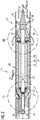
- FIG. 2shows a preferred embodiment of the blood pump with the motor part 11 and the pump part 12 firmly connected thereto.
- the motor part 11has an elongated housing 20 in which the electric motor 21 is accommodated.
- the stator 24 of the electric motor 21has in the usual manner numerous windings arranged circumferentially distributed and a magnetic yoke 28 in the longitudinal direction. It is firmly connected to the motor housing.
- the stator 24surrounds the rotor 26 connected to the motor shaft 25, which consists of permanent magnets magnetized in the effective direction.
- the motor shaft 25extends over the entire length of the motor housing 20 and projects distally from it. There it carries an impeller 34 with blades 36 or pump blades projecting therefrom, which rotate in a tubular pump housing 32, which in turn is firmly connected to the motor housing 20.
- the flexible catheter 14is sealingly connected to the proximal end of the motor housing 20. Electrical cables 23 for power supply and control of the electric motor 21 run through the catheter 14. Furthermore, a rinsing liquid line 29 runs through the catheter 14 and passes through the proximal end wall 22 of the motor housing 20. Flushing liquid is fed through the flushing liquid line 29 into the interior of the motor housing 20 and exits through the end face 30 at the distal end of the motor housing.
- the purge pressureis selected so that it is above the applied blood pressure in order to prevent blood from entering the motor housing, and is between 300 and 1400 mmHg depending on the application.
- the motor shaft 25is mounted on the one hand at the proximal end of the motor housing and on the other hand at the distal end of the motor housing in radial bearings 27 and 31.
- the radial bearingsare each designed as simple plain bearings.
- the motor shaft 25is also axially supported in the motor housing 20.
- the thrust bearing 40is also designed as a plain bearing.
- the thrust slide bearing 40is described below with reference to FIG Figure 3 explained in more detail. It serves to absorb axial forces of the motor shaft 25, which act in the distal direction when the impeller 34 conveys from distal to proximal. If the blood pump is used to deliver blood, or only in the opposite direction, a corresponding axial sliding bearing 40 (also / or) must be provided in a corresponding manner on the proximal end of the motor housing 20.
- the blood pump according to Fig. 2can alternatively be used without rinsing liquid for a short period of a few hours.
- the slide bearingsare lubricated once, and the distal slide bearing 31 is also provided with a radial lip seal to prevent the entry of blood.
- a flushing liquid linecan then advantageously be dispensed with overall.
- Figure 3shows section III Figure 2 in greater detail.
- the radial slide bearing 31 and the axial slide bearing 40can be seen.
- the bearing gap of the radial slide bearing 31is formed on the one hand by the peripheral surface of the motor shaft 25, which is DLC-coated, and on the other hand by the surface of the through hole in the distal end wall 30 of the motor housing 20, which as a ceramic part, for example made of zirconium oxide.
- the bearing gap of the axial plain bearing 40is formed on the one hand by the axially inner surface 41 of the end wall 30 and an opposite surface 42.
- This opposite surface 42is part of a ceramic disk 44, which sits distally from the rotor 26 on the motor shaft 25 and rotates with the rotor 26.
- a channel 43 in the bearing gap surface 41 of the end wall 30ensures that rinsing liquid can flow between the bearing gap surfaces 41 and 42 of the axial sliding bearing 40 to the radial sliding bearing 31 and can emerge distally from the motor housing 20.
- the rinsing liquidis selected with a viscosity of at least 1.2 mPa • s at 37 ° C. For example, 20% glycose solution has proven to be suitable.
- Axial plain bearing 40 shownis a normal plain bearing. Hydrostatic plain bearing variants are described below in relation to the Figures 6A / B, 7 and 8.
- the axial gap of the axial plain bearing 40is very small, with a few ⁇ m, as shown.
- a combined radial-axial sliding bearing 46 with a concave bearing shell, in which a convex bearing surface runscan also be realized.
- Such a variantis in Figure 4 shown using a spherical plain bearing 46.
- the bearing gap surface 41is spherically concave, and the opposite bearing gap surface 42 is correspondingly spherically convex.
- the channel 43is again in the stationary bearing gap surface 41 of the end wall 30.
- the fixed bearing gap surface 41 of the end wall 30can be made convex and the opposite bearing gap surface 42 can be concave.
- the surfaces 42, 43can also be conical instead of spherical.
- a corresponding radial-axial slide bearingis preferably provided on both sides of the motor housing 20 in order not to permit any radial offset when the shaft 25 moves axially.
- the advantage of a combined axial-radial plain bearinglies in the higher load capacity. However, the larger friction diameter is disadvantageous.
- Figure 5shows the radial bearing 27 at the proximal end of the motor housing 20.
- the motor shaft 25is provided with a DLC coating and runs in a bearing bush, which forms an integral part of the proximal end wall 22 of the motor housing 20, which in turn is made of ceramic.
- the radial slide bearing 27corresponds to the radial slide bearing 31.
- the end wall 22Distributed over the circumference of the end wall 22 are three axially extending grooves 50 at a distance of 120 °, of which in Figure 2 only one can be seen. Thin connecting wires 51 lead through these grooves 50 to the windings of the stator 24.
- the connecting wires 51are soldered onto the proximal side of the end wall 20, the soldering point 52 being made conductive beforehand with a local copper coating.
- the end of the power supply line 23is also soldered to the same soldering point 52.
- the wires of the stator windingscan be connected to the power supply lines using all conventional joining methods (soldering, welding, clamping, laser welding, gap welding, contact gluing, etc.).
- the end wall 22, including the connecting wires 51 and the soldering points 52is then covered with a plastic material, the motor windings of the stator also being covered at the same time. This can be done, for example, in a vacuum potting.
- the blood pump described abovedispenses with radial ball bearings for mounting the motor shaft 25, which are difficult to assemble and have a minimum size of 3 mm. This makes it possible to manufacture pumps with even smaller outside diameters of, for example, only 3 mm.
- the lifespan of this blood pumpis longer than that with radial ball bearings significantly increased due to less wear. Running times> 30 days can be realized with little wear. The latter is extremely important, since the bearing and the shock-free running of the impeller are crucial for low blood damage.
- Figure 6Ashows a top view of the surface 41 of the distal end wall 30 of the motor housing 20 according to an alternative embodiment.
- Figure 6Bshows a development of the surface 41 Figure 6A .
- the surface 41itself is stationary.
- the direction indicated by the arrowindicates the direction in which the opposite surface 42 of the sliding bearing 40 is moving. This then also corresponds to the direction in which the lubricating film moves within the bearing gap relative to the stationary surface 41.
- the surface 41has ramps arranged one behind the other, which together with the opposite moving surface 42, which is flat, form converging gaps.
- a hydrodynamic pressurebuilds up in the lubricating film, which ensures that the surfaces forming the bearing gap remain at a distance.
- a formation of the rotating surface with the ramp-like structures according to the Figures 6A and 6Bis an advantage for the performance of the axial plain bearing, but leads to an increased radial conveying effect in the bearing gap, which opposes the direction of flow of the flushing liquid.
- Figure 7is the simplest form of a ramp-like realization of the convergent gap in the form of a swashplate.
- the disc 44is simply installed obliquely or ground minimally obliquely.
- the inclinationis typically 1 to 5 ⁇ m.
- Figure 8shows another variant for a hydrodynamically acting surface of the axial sliding bearing 40. It is a so-called spiral groove bearing, which is preferably formed on the moving surface of the bearing gap, accordingly on the surface 42 of the ceramic disk 44. In this case, the surface 42 several grooves 45 arranged spirally.
- the grooves 45are in Figure 8 only indicated schematically. If the ceramic disc 44 in the direction indicated by the arrow in Figure 8 indicated direction rotates, the lubricating film along the grooves 45 radially inward promotes and builds up a pressure there, which in turn ensures that the surfaces forming the bearing gap are kept at a distance from one another.
Landscapes
- Health & Medical Sciences (AREA)
- Heart & Thoracic Surgery (AREA)
- Engineering & Computer Science (AREA)
- Cardiology (AREA)
- General Health & Medical Sciences (AREA)
- Anesthesiology (AREA)
- Biomedical Technology (AREA)
- Hematology (AREA)
- Life Sciences & Earth Sciences (AREA)
- Animal Behavior & Ethology (AREA)
- Mechanical Engineering (AREA)
- Public Health (AREA)
- Veterinary Medicine (AREA)
- Vascular Medicine (AREA)
- Physics & Mathematics (AREA)
- Fluid Mechanics (AREA)
- Transplantation (AREA)
- External Artificial Organs (AREA)
- Structures Of Non-Positive Displacement Pumps (AREA)
- Sliding-Contact Bearings (AREA)
- Support Of The Bearing (AREA)
Description
Translated fromGermanDie Erfindung betrifft eine intravasale Blutpumpe zur Unterstützung des Blutkreislaufs im menschlichen oder gegebenenfalls auch tierischen Körpers. Sie wird perkutan beispielsweise in die Femoralarterie eingeführt und durch das Gefäßsystem des Körpers hindurchgeführt, um beispielsweise die Pumparbeit im Herzen zu unterstützen oder zu ersetzen. Die Erfindung betrifft gleichermaßen ein eine solche intravasale Blutpumpe umfassendes System sowie ein Verfahren zur Unterstützung des Blutkreislaufs unter Verwendung einer solchen intravasalen Blutpumpe.The invention relates to an intravascular blood pump to support blood circulation in the human or possibly also the animal body. It is introduced percutaneously, for example, into the femoral artery and passed through the vascular system of the body, for example to support or replace pumping work in the heart. The invention also relates to a system comprising such an intravascular blood pump and to a method for supporting the blood circulation using such an intravascular blood pump.
Die Anforderungen an derartige Blutpumpen hinsichtlich Einsatzdauer und geringer Größe nehmen ständig zu. Die kleinsten Pumpen dieser Art haben einen Außendurchmesser von etwa 4 mm. Eine weitere Reduzierung des Außendurchmessers wird unter anderem durch die in der Pumpe zum Einsatz kommenden Maschinenelemente begrenzt, die nicht in beliebig geringen Größen zur Verfügung stehen. Darüber hinaus sind die Maschinenelemente enormen Belastungen ausgesetzt, denn aufgrund der geringen Baugröße und der doch beträchtlichen zu fördernden Volumenströme im menschlichen Blutkreislauf arbeiten diese Pumpen mit hohen Drehzahlen von mehreren 10.000 Umdrehungen pro Minute. Waren diese Art von Blutpumpen ursprünglich nur zur kurzzeitigen Herzunterstützung bestimmt, so werden sie zunehmend auch zur Langzeittherapie über mehrere Tage bis zu Wochen eingesetzt.The requirements for such blood pumps in terms of operating time and small size are constantly increasing. The smallest pumps of this type have an outer diameter of approximately 4 mm. A further reduction in the outside diameter is limited, among other things, by the machine elements used in the pump, which are not available in arbitrarily small sizes. In addition, the machine elements are exposed to enormous loads, because due to the small size and the considerable volume flows to be promoted in the human bloodstream, these pumps operate at high speeds of several 10,000 revolutions per minute. While these types of blood pumps were originally only intended for short-term heart support, they are increasingly being used for long-term therapy over several days to weeks.
Aus
Die intravasale Blutpumpe fördert das Blut normalerweise von distal nach proximal durch das Pumpengehäuse hindurch und am Motorgehäuse vorbei. Auch eine umgekehrte Förderung ist möglich. In beiden Fällen erzeugt das Flügelrad bei der Blutförderung Axialkräfte, die über die Motorwelle auf die Lagerungen übertragen und von dem Radialkugellager aufgenommen werden.The intravascular blood pump typically delivers blood from distal to proximal through the pump housing and past the motor housing. Reverse funding is also possible. In both cases, the impeller generates axial forces during blood delivery, which are transmitted to the bearings via the motor shaft and absorbed by the radial ball bearing.
Ausgehend von diesem Stand der Technik ist es die Aufgabe der vorliegenden Erfindung, Maßnahmen vorzuschlagen, wie die Baugröße derartiger intravasaler Blutpumpen weiter reduziert und ihre Lebensdauer erhöht werden kann.Starting from this prior art, it is the object of the present invention to propose measures as to how the size of such intravascular blood pumps can be further reduced and their lifespan increased.
Diese Aufgabe wird durch eine intravasale Blutpumpe mit den Merkmalen des Anspruchs 1 gelöst. In davon abhängigen Ansprüchen sind vorteilhafte Weiterbildungen und Ausgestaltungen der Erfindung angegeben.This object is achieved by an intravascular blood pump with the features of claim 1. Advantageous developments and refinements of the invention are specified in claims dependent thereon.
Erfindungsgemäß sind Anschlussdrähte des Elektromotors proximal von dem proximal gelegenen Radiallager auf einer Oberfläche des Motorgehäuses mit den Stromversorgungsleitungen verlötet. Dies ist vorteilhaft, weil das direkte elektrische Verbinden der Anschlussdrähte des Elektromotors mit den Stromversorgungsleitungen aufgrund der geringen Dicke der Anschlussdrähte und der vergleichsweise großen Dicke der Stromversorgungsleitungen Schwierigkeiten bereiten kann. Wenn die betreffende Oberfläche des Elektromotors aus einem Kunststoff oder aus Keramik besteht, wie nachfolgend noch erläutert wird, so kann der Lötstellenbereich vor dem Verlöten leitfähig beschichtet werden, beispielsweise mit Kupfer, und das Verlöten der Anschlussdrähte und der Versorgungsleitungen erfolgt jeweils separat in diesem Bereich.According to the invention, connecting wires of the electric motor are soldered proximally from the proximal radial bearing on a surface of the motor housing to the power supply lines. This is advantageous because the direct electrical connection of the connecting wires of the electric motor to the power supply lines can cause difficulties due to the small thickness of the connecting wires and the comparatively large thickness of the power supply lines. If the surface of the electric motor in question consists of a plastic or ceramic, as will be explained in the following, the soldering area can be coated in a conductive manner before the soldering, for example with copper, and the connection wires and the supply lines are soldered separately in this area.
Vorzugsweise wird der betreffende Teil des Motorgehäuses anschließend in Kunststoff eingebettet, wobei die Lötstellen und vorzugsweise auch die Motorwicklungen mit eingebettet werden, so dass die Lötstellen einerseits elektrisch isoliert und andererseits mechanisch geschützt sind.The relevant part of the motor housing is then preferably embedded in plastic, the solder joints and preferably also the motor windings being embedded, so that the solder joints are electrically insulated on the one hand and mechanically protected on the other hand.
Die Anschlussdrähte des in dem Motorgehäuse aufgenommenen Elektromotors werden normalerweise um das proximal gelegene Radiallager außen herumgeführt und mit den im Katheter verlaufenden Stromversorgungsleitungen elektrisch leitend verbunden, insbesondere verlötet. Gemäß einer bevorzugten Ausgestaltung der Erfindung werden die Anschlussdrähte des Elektromotors nun durch den Außenring des Radiallagers hindurch oder vorteilhafterweise in einer oder mehreren radial außen liegenden Nuten des Außenrings geführt. Dadurch wird Bauraum in radialer Richtung gespart, was wiederum positiv ist für die Entwicklung von Blutpumpen mit kleinem Außendurchmesser. So kann beispielsweise Bauraum für eine Druckmessung und deren Durchführung am proximalen Motorende erreicht werden.The connecting wires of the electric motor accommodated in the motor housing are normally led around the proximal radial bearing on the outside and connected in an electrically conductive manner, in particular soldered, to the power supply lines running in the catheter. According to a preferred embodiment of the invention, the connecting wires of the electric motor are now passed through the outer ring of the radial bearing or advantageously in one or more radially outer grooves of the outer ring. This saves space in the radial direction, which in turn is positive for the development of blood pumps with a small outside diameter. For example, space for a pressure measurement and its implementation at the proximal end of the motor can be achieved.
Die erfindungsgemäße Blutpumpe zeichnet sich des Weiteren dadurch aus, dass sie mittels eines Axiallagers axial in dem Motorgehäuse gelagert ist, wobei das Axiallager ein Axialgleitlager oder kombiniertes Radial-Axial-Gleitlager ist. Die axialen Kräfte der Motorwelle brauchen somit nicht mehr von dem am proximalen Ende des Motorgehäuses angeordneten Radialkugellager aufgenommen zu werden. Das Radialkugellager kann daher entsprechend kleiner gebaut werden oder durch ein anderes klein bauendes Radiallager, insbesondere ein Radialgleitlager, ersetzt werden. Dadurch wiederum ist es möglich, Blutpumpen mit einem weiter reduzierten Außendurchmesser zu entwickeln. Gleichzeitig verlängert sich durch diese Maßnahme die Lebensdauer der Blutpumpe, weil das Radiallager aufgrund der verringerten axialen Kräfte, zu deren Aufnahme ein Radiallager ohnehin nicht primär bestimmt ist, entlastet ist, so dass es einem geringeren Verschleiß unterliegt.The blood pump according to the invention is further characterized in that it is mounted axially in the motor housing by means of an axial bearing, the axial bearing being an axial slide bearing or a combined radial-axial slide bearing. The axial forces of the motor shaft therefore no longer have to be absorbed by the radial ball bearing arranged at the proximal end of the motor housing. The radial ball bearing can therefore be built correspondingly smaller or replaced by another small radial bearing, in particular a radial sliding bearing. This in turn makes it possible to develop blood pumps with a further reduced outside diameter. At the same time, this measure extends the lifespan of the blood pump because the radial bearing is relieved due to the reduced axial forces, which a radial bearing is not intended to absorb anyway, so that it is subject to less wear.
Alternativ kann die Erfindung in vorhandene Baugrößen integriert werden, um die Lebensdauer zu erhöhen und den Komplexitätsgrad zu reduzieren.Alternatively, the invention can be integrated into existing sizes in order to increase the service life and reduce the degree of complexity.
Die auf die Motorwelle wirkenden Axialkräfte sind der Förderrichtung entgegengesetzt. Wenn die Blutpumpe dazu eingerichtet ist, alternativ in proximaler Richtung und in distaler Richtung zu fördern, so wirken auf die Motorwelle in dem einen Fall Axialkräfte in distaler Richtung und in dem anderen Fall in proximaler Richtung. Bei einer solchen Blutpumpe sind dementsprechend zwei Axialgleitlager oder Axial-Radial-Gleitlager in dem Motorgehäuse zur axialen Lagerung der Motorwelle vorzusehen. Das Axialgleitlager kann in einfacher Weise durch eine auf der Motorwelle angeordnete Scheibe gebildet werden, die sich gegen eine umlaufende Schulter des Motorgehäuses abstützt. Im Falle eines Axial-Radial-Gleitlagers besitzt die Scheibe eine konvexe oder konkave, insbesondere sphärische, Lagerfläche. Nachfolgend wird der Begriff "Axialgleitlager" synonym für beide Varianten, Axialgleitlager und Radial-Axial-Gleitlager, verwendet.The axial forces acting on the motor shaft are opposite to the conveying direction. If the blood pump is set up to alternatively deliver in the proximal direction and in the distal direction, then axial forces act on the motor shaft in the distal direction in one case and in the proximal direction in the other case. In such a blood pump, two axial slide bearings or axial-radial slide bearings are accordingly to be provided in the motor housing for the axial mounting of the motor shaft. The axial sliding bearing can be formed in a simple manner by a disk which is arranged on the motor shaft and which is supported against a circumferential shoulder of the motor housing. In the case of an axial-radial plain bearing, the disk has a convex or concave, in particular spherical, bearing surface. In the following, the term "axial plain bearing" is used synonymously for both variants, axial plain bearings and radial-axial plain bearings.
Das Motorgehäuse selbst ist mit einer geeigneten Flüssigkeit gefüllt, die einen Schmierfilm im Lagerspalt des Axialgleitlagers bildet. Alternativ kann durch eine Spülflüssigkeitszuleitung zugeführte Spülflüssigkeit, die das am distalen Ende des Motorgehäuses liegende Radiallager durchströmt, auch den Lagerspalt des Axialgleitlagers durchströmen und auf diese Weise dazu genutzt werden, den Schmierfilm im Lagerspalt zu bilden. Um in diesem Fall sicherzustellen, dass die Spülflüssigkeit das distale Radiallager mit einem Druck erreicht, der über dem anliegenden Blutdruck liegt, kann in zumindest einer der den Lagerspalt des Axialgleitlagers bildenden Oberflächen ein Kanal vorgesehen werden, der den Lagerspalt von radial außen nach radial innen durchsetzt, so dass die Spülflüssigkeit durch diesen Kanal zum distalen Radiallager fließen kann. Dieser Kanal muss nicht notwendigerweise in einer Lagerspaltoberfläche liegen, sondern kann auch als separater Kanal oder als Bohrung realisiert sein. Den Kanal in einer der Lagerspaltoberflächen vorzusehen hat aber den Vorteil, dass sich der Schmierfilm im Lagerspalt weniger erwärmt, weil ständig ein Teil des Schmierfilms durch nachströmende Spülflüssigkeit ersetzt wird. Vorzugsweise befindet sich der Kanal in der stationären Lagerspaltoberfläche, um die radiale Förderleistung zu minimieren.The motor housing itself is filled with a suitable liquid, which forms a lubricating film in the bearing gap of the axial plain bearing. Alternatively, flushing liquid supplied through a flushing liquid supply line, which flows through the radial bearing located at the distal end of the motor housing, can also flow through the bearing gap of the axial plain bearing and can be used in this way to form the lubricating film in the bearing gap. In this case, in order to ensure that the irrigation fluid reaches the distal radial bearing at a pressure which is above the applied blood pressure, a channel can be provided in at least one of the surfaces forming the bearing gap of the axial sliding bearing, said channel passing through the bearing gap from radially outside to radially inside , so that the irrigation fluid can flow through this channel to the distal radial bearing. This channel does not necessarily have to lie in a bearing gap surface, but can also be implemented as a separate channel or as a bore. However, providing the channel in one of the bearing gap surfaces has the advantage that the lubricating film in the bearing gap heats up less because part of the lubricating film is constantly replaced by rinsing liquid flowing in. The channel is preferably located in the stationary bearing gap surface in order to minimize the radial delivery rate.
Vorzugsweise ist das Axialgleitlager als hydrodynamisches Gleitlager ausgebildet. Im Gegensatz zu einem einfachen Gleitlager wird in einem hydrodynamischen Gleitlager durch Pumpwirkung der beiden relativ zueinander bewegten Oberflächen ein Druck im Schmierfilm aufgebaut. Dazu kann der Lagerspalt gemäß einer bevorzugten Variante in Umfangsrichtung des Axialgleitlagers bereichsweise als konvergierender Spalt ausgebildet sein. Dabei ist vorzugsweise die bewegte Oberfläche eben, das heißt die gegenüberliegende stationäre Oberfläche des Lagerspalts weist Rampen auf, die in Drehrichtung der bewegten Oberfläche zur bewegten Oberfläche hin konvergieren. So wird im Lagerspalt ein Keil gebildet, in den die Schmierflüssigkeit hinein transportiert wird, wodurch ein Druck aufgebaut wird, aufgrund dessen sich die bewegte Oberfläche von der statischen Oberfläche entfernt. In diesem Zustand herrscht Gleitreibung auf einem Flüssigkeitsfilm, die quasi verschleißfrei ist. Da die Blutpumpe im Normalfall kontinuierlich mit hoher Drehzahl fördert, ist die Blutpumpe besonders verschleißarm und dementsprechend für Langzeitanwendungen geeignet.The axial plain bearing is preferably designed as a hydrodynamic plain bearing. In contrast to a simple plain bearing, a pressure in the lubricating film is built up in a hydrodynamic plain bearing by the pumping action of the two surfaces which are moved relative to one another. For this purpose, according to a preferred variant, the bearing gap can be designed in regions as a converging gap in the circumferential direction of the axial sliding bearing. In this case, the moving surface is preferably flat, that is to say the opposite stationary surface of the bearing gap has ramps which converge towards the moving surface in the direction of rotation of the moving surface. In this way, a wedge is formed in the bearing gap, into which the lubricant is transported, whereby a pressure is built up, due to which the moving surface moves away from the static surface. In this state, there is sliding friction on a liquid film that is practically wear-free. Since the blood pump normally delivers continuously at high speed, the blood pump is particularly low-wear and therefore suitable for long-term use.
In der einfachsten Ausführungsform kann die bewegte Scheibe als Taumelscheibe ausgeführt sein und schlicht durch die Schrägstellung den kovergenten Spalt bzw. Keil bilden.In the simplest embodiment, the moving disk can be designed as a swashplate and simply form the convergent gap or wedge due to the inclined position.
Anstelle eines Lagerspalts mit konvergierenden Oberflächenzonen kann eine der den Lagerspalt bildenden Oberflächen eine oder mehrere spiralförmig angeordnete Rillen aufweisen. In diesem Fall wird die Schmierflüssigkeit durch die Relativbewegung der beiden Oberflächen entlang der Rillen zur Lagermitte gepumpt und baut dort einen Druck auf, der wiederum dazu führt, dass sich die beiden Oberflächen voneinander entfernen. Bei der Spiralrillenlagervariante ist es bevorzugt, die spiralförmig angeordneten Rillen in der bewegten Oberfläche vorzusehen, weil so die Schmierflüssigkeitsförderung in die Rillen hinein effektiver ist.Instead of a bearing gap with converging surface zones, one of the surfaces forming the bearing gap can have one or more spirally arranged grooves. In this case, the lubricant is pumped by the relative movement of the two surfaces along the grooves to the center of the bearing and builds up a pressure there, which in turn leads to the two surfaces moving away from one another. In the spiral groove bearing variant, it is preferred to have the spirally arranged grooves in the moving surface to be provided because the lubricant delivery into the grooves is more effective.
Sollte bauartbedingt der Axialschub (Fax Rotor) der Pumpvorrichtung größer sein als die Tragfähigkeit des Axialgleitlagers, so kann der Axialschub der Pumpvorrichtung durch eine geeignete axiale Anordnung des rotierenden Magneten im Motor teilweise kompensiert werden. Erfindungsgemäß verhält sich er rotierende Magnet wie ein Tauchmagnet, der sich magnetisch in der Mitte des statischen Motorteils aufhalten will. Wird dieser nunmehr aus dieser Ruhelage herausgezogen, so entsteht eine Magnetkraft in umgekehrter Richtung (Fax Magnet). Diese Kraft kann in Richtung des Axialschubs (Fax Rotor) zur weiteren axialen Stabilisierung oder in entgegengesetzter Richtung eingesetzt werden und das axiale Gleitlager entlasten. Weiterhin kann durch Variation des Drucks der Spülflüssigkeit die resultierende Kraft auf das Axiallager eingestellt werden (vgl.
Weiter bevorzugt ist es, wenn die den Lagerspalt des Axialgleitlagers bildenden Oberflächen aus Keramik bestehen, vorzugsweise Zirkoniumoxid. Aus Keramik lassen sich hochfeste, verschleißarme Oberflächen herstellen. Insbesondere kann in einfacher Weise das gesamte distale Ende des Motorgehäuses, einschließlich der Oberfläche für das Axialgleitlager, aus einem einstückigen Keramikteil hergestellt werden, so dass die Gesamtherstellungskosten der Blutpumpe gering sind.It is further preferred if the surfaces forming the bearing gap of the axial sliding bearing consist of ceramic, preferably zirconium oxide. High-strength, low-wear surfaces can be produced from ceramics. In particular, the entire distal end of the motor housing, including the surface for the axial sliding bearing, can be produced in a simple manner from a one-piece ceramic part, so that the overall production costs of the blood pump are low.
Gemäß einer bevorzugten Weiterbildung der Erfindung werden auch die Radiallager für die Motorwelle am proximalen Ende und am distalen Ende des Motorgehäuses jeweils als Gleitlager ausgebildet. Da diese Radiallagerungen im wesentlichen nur dazu dienen, die Welle zentrisch genau zu führen und dementsprechend nur geringe radiale Kräfte aufzunehmen sind, können sie als einfache Gleitlager ausgeführt werden. Ein Radialgleitlager beansprucht deutlich weniger Bauraum in radialer Richtung als ein Wälzkörperlager mit seinen Innen- und Außenringen. Dies wirkt sich wieder positiv auf die Möglichkeiten aus, Blutpumpen mit kleinem Außendurchmesser herzustellen.According to a preferred development of the invention, the radial bearings for the motor shaft at the proximal end and at the distal end of the motor housing are each designed as slide bearings. Since these radial bearings essentially only serve to precisely guide the shaft centrally and, accordingly, only small radial forces are to be absorbed, they can be designed as simple plain bearings. A radial plain bearing takes up significantly less space in the radial direction than a rolling element bearing with its inner and outer rings. Again, this has a positive effect on the possibilities of manufacturing blood pumps with a small outside diameter.
Insbesondere ist es bevorzugt, das am proximalen Ende des Motorgehäuses liegende Radialgleitlager aus Keramik herzustellen, wobei das Keramiklager direkt an der Umfangsoberfläche der Motorwelle anliegt. In entsprechender Weise kann auch das am distalen Ende des Motorgehäuses liegende Radiallager ausgebildet sein. Die der Keramikoberfläche gegenüberliegende Oberfläche der Motorwelle, welche zusammen mit der Keramikoberfläche den Lagerspalt des Radialgleitlagers bildet, ist vorzugsweise mit einer amorphen Kohlenstoffbeschichtung (DLC = Diamant-Like-Carbon bzw. Diamant-Like-Coating) beschichtet. DLC-Schichten sind besonders verschleißfest und reibungsarm. Sie sind nur wenige Mikrometer dick und können beispielsweise im chemischen Dampfabscheidungsverfahren (CVD) oder physikalischen Dampfabscheidungsverfahren (PVD) erzeugt werden. Alternativ kann die Welle aus einer bruchsicheren Keramik gefertigt werden.In particular, it is preferred to manufacture the radial slide bearing located at the proximal end of the motor housing from ceramic, the ceramic bearing lying directly on the peripheral surface of the motor shaft. The radial bearing located at the distal end of the motor housing can also be designed in a corresponding manner. The surface opposite the ceramic surface The motor shaft, which together with the ceramic surface forms the bearing gap of the radial sliding bearing, is preferably coated with an amorphous carbon coating (DLC = diamond-like carbon or diamond-like coating). DLC layers are particularly wear-resistant and low-friction. They are only a few micrometers thick and can be produced, for example, by chemical vapor deposition (CVD) or physical vapor deposition (PVD). Alternatively, the shaft can be made from break-proof ceramic.
Im Betrieb wird die Blutpumpe an eine Spülflüssigkeitsquelle angeschlossen und Flüssigkeit durch die Spülflüssigkeitsleitung hindurch ins Motorgehäuse geleitet. Die Spülflüssigkeit fließt dann durch das Axialgleitlager und weiter durch das distale Radiallager hindurch. Im Axialgleitlager bildet es den Schmierfilm im Lagerspalt. Der Druck, mit dem die Spülflüssigkeit durch das Motorgehäuse strömt, wirkt sich jedoch negativ auf die Weite des Lagerspalts aus. Denn je höher der Spülflüssigkeitsdruck ist, desto geringer wird die Lagerspaltweite und desto dünner ist der Schmierfilm zwischen den Gleitflächen. Je dünner der Schmierfilm ist, desto größer ist wiederum der zur Überwindung der Reibkräfte notwendige Motorstrom zum Antreiben des Elektromotors. Dies ist ungünstig für die Steuerung der Blutpumpe, weil man normalerweise anhand von hinterlegten Kennlinien allein auf Basis des Motorstroms und der Drehzahl (beides bekannte Größen) das aktuelle Fördervolumen ermittelt. Wenn sich der Spülflüssigkeitsdruck zusätzlich auf den Motorstrom auswirkt, so wäre eine weitere Einflussgröße zu berücksichtigen. In Anbetracht der Tatsache, dass derselbe Blutpumpentyp für unterschiedlichste Anwendungen mit unterschiedlichen Spülflüssigkeitsdrücken zwischen 300 und 1400 mmHg betrieben werden kann, ist es wichtig, eine Abhängigkeit des Motorstroms vom Spülflüssigkeitsdruck zu vermeiden.In operation, the blood pump is connected to a flushing liquid source and liquid is fed through the flushing liquid line into the motor housing. The irrigation fluid then flows through the axial plain bearing and on through the distal radial bearing. In the axial slide bearing, it forms the lubricating film in the bearing gap. However, the pressure with which the flushing fluid flows through the motor housing has a negative effect on the width of the bearing gap. Because the higher the flushing fluid pressure, the smaller the bearing gap width and the thinner the lubricating film between the sliding surfaces. The thinner the lubricating film, the greater the motor current needed to overcome the frictional forces to drive the electric motor. This is unfavorable for the control of the blood pump because normally the current delivery volume is determined on the basis of stored characteristic curves based solely on the motor current and the speed (both known quantities). If the flushing fluid pressure also affects the motor current, another influencing variable would have to be taken into account. In view of the fact that the same type of blood pump can be operated for different applications with different flushing fluid pressures between 300 and 1400 mmHg, it is important to avoid a dependence of the motor current on the flushing fluid pressure.
Dies kann tatsächlich erreicht werden, wenn als Spülflüssigkeit eine Flüssigkeit mit einer Viskosität gewählt wird, die deutlich höher ist als die Viskosität von Wasser (η = 0,75 mPa • s bei 37°C). Denn mit einer hochviskosen Spülflüssigkeit wird der Flüssigkeitsfilm selbst bei hohen Drücken aufrecht erhalten und die Reibung des Axialgleitlagers ist dementsprechend unabhängig vom Spülflüssigkeitsdruck. Es hat sich herausgestellt, dass man mit einer Spülflüssigkeit, deren Viskosität bei 37°C ca. 1,2 mPa • s beträgt oder noch darüber liegt, das Axialgleitlager als einfaches Gleitlager ausbilden kann und nicht als hydrodynamisches Gleitlager auszubilden braucht. Gute Ergebnisse wurden beispielsweise mit einer ≥ 20%-igen Glykoselösung zwischen Keramikoberflächen aus Zirkoniumoxid erzielt.This can actually be achieved if a liquid with a viscosity that is significantly higher than the viscosity of water (η = 0.75 mPa • s at 37 ° C) is selected as the rinsing liquid. Because with a highly viscous flushing liquid, the liquid film is maintained even at high pressures and the friction of the axial plain bearing is therefore independent of the flushing liquid pressure. It turned out that with a rinsing liquid, whose viscosity at 37 ° C is approx. 1.2 mPa • s or even higher, the axial plain bearing can be a simple plain bearing and does not need to be a hydrodynamic plain bearing. Good results have been achieved, for example, with a ≥ 20% glycose solution between ceramic surfaces made of zirconium oxide.
Nachfolgend wird die Erfindung beispielhaft anhand der begleitenden Zeichnungen erläutert. Darin zeigen:
- Figur 1
- eine schematische Darstellung der Einführung einer Blutpumpe vor den linken Ventrikel, mit Positionierung ihrer Ansaugkanüle im linken Ventrikel,
- Figur 2
- einen schematischen Längsschnitt eines Ausführungsbeispiels der Blutpumpe,
- Figur 3
- eine vergrößerte Darstellung der Einzelheit III aus
Figur 2 , - Figur 4
- eine Variante zur Einzelheit III aus
Figur 3 , - Figur 5
- eine vergrößerte Darstellung der Einzelheit IV aus
Figur 2 , - Figuren 6A und 6B
- eine Axialgleitlageroberfläche in Draufsicht und als Abwicklung gemäß einem ersten Ausführungsbeispiel,
- Figur 7
- eine Axialgleitlageroberfläche im Querschnitt gemäß einem zweiten Ausführungsbeispiel, und
- Figur 8
- eine Axialgleitlageroberfläche in Draufsicht gemäß einem dritten Ausführungsbeispiel.
- Figure 1
- 1 shows a schematic illustration of the introduction of a blood pump in front of the left ventricle, with its suction cannula positioned in the left ventricle,
- Figure 2
- 2 shows a schematic longitudinal section of an exemplary embodiment of the blood pump,
- Figure 3
- an enlarged view of detail III
Figure 2 , - Figure 4
- a variant of detail III
Figure 3 , - Figure 5
- an enlarged view of detail IV
Figure 2 , - Figures 6A and 6B
- an axial plain bearing surface in plan view and as a development according to a first embodiment,
- Figure 7
- an axial plain bearing surface in cross section according to a second embodiment, and
- Figure 8
- an axial plain bearing surface in plan view according to a third embodiment.
In
Der Einsatz der Blutpumpe ist nicht auf die in
An das proximale Ende des Motorgehäuses 20 schließt sich der flexible Katheter 14 abdichtend an. Durch den Katheter 14 verlaufen elektrische Kabel 23 zur Stromversorgung und Steuerung des Elektromotors 21. Desweiteren verläuft durch den Katheter 14 eine Spülflüssigkeitsleitung 29, welche die proximale Stirnwand 22 des Motorgehäuses 20 durchsetzt. Spülflüssigkeit wird durch die Spülflüssigkeitsleitung 29 ins Innere des Motorgehäuses 20 gespeist und tritt durch die Stirnseite 30 am distalen Ende des Motorgehäuses aus. Der Spüldruck ist so gewählt, dass er über dem anliegenden Blutdruck liegt, um auf diese Weise zu verhindern, dass Blut ins Motorgehäuse eindringt, und liegt je nach Anwendungsfall zwischen 300 und 1400 mmHg.The
Bei einer Rotation des Flügelrades 34 wird Blut durch die stirnseitige Ansaugöffnung 37 des Pumpengehäuses 32 angesaugt und in axialer Richtung im Pumpengehäuse 32 nach hinten befördert. Durch Austrittsöffnungen 38 im Pumpengehäuse 32 strömt das Blut aus dem Pumpenteil 12 aus und weiter entlang dem Motorgehäuse 20. Hierdurch wird der Abtransport der im Antrieb erzeugten Wärme sichergestellt. Es ist auch möglich, den Pumpenteil mit umgekehrter Förderrichtung zu betreiben, wobei Blut an dem Motorgehäuse 20 entlang angesaugt wird und aus der Öffnung 37 austritt.When the
Die Motorwelle 25 ist einerseits am proximalen Ende des Motorgehäuses und andererseits am distalen Ende des Motorgehäuses in Radiallagern 27 und 31 gelagert. Die Radiallager sind in diesem Ausführungsbeispiel jeweils als einfache Gleitlager ausgeführt. Darüber hinaus ist die Motorwelle 25 in dem Motorgehäuse 20 auch axial gelagert. Das Axiallager 40 ist ebenfalls als Gleitlager ausgeführt. Das Axialgleitlager 40 wird nachfolgend in Bezug auf
Die Blutpumpe gemäß
Der Lagerspalt des Axialgleitlagers 40 wird einerseits durch die axial innen liegende Oberfläche 41 der Stirnwand 30 und eine ihr gegenüberliegende Oberfläche 42 gebildet. Diese gegenüberliegende Oberfläche 42 ist Bestandteil einer Keramikscheibe 44, die auf der Motorwelle 25 distal vom Rotor 26 sitzt und sich mit dem Rotor 26 dreht. Ein Kanal 43 in der Lagerspaltoberfläche 41 der Stirnwand 30 stellt sicher, dass Spülflüssigkeit zwischen den Lagerspaltoberflächen 41 und 42 des Axialgleitlagers 40 hindurch zum Radialgleitlager 31 fließen und distal aus dem Motorgehäuse 20 austreten kann. Die Spülflüssigkeit wird mit einer Viskosität von mindestens 1,2 mPa • s bei 37°C gewählt. Als geeignet hat sich beispielsweise 20%-Glykoselösung erwiesen. Das in
Anstelle des Axialgleitlagers 40 und Radialgleitlagers 31 kann auch ein kombiniertes Radial-Axial-Gleitlager 46 mit einer konkaven Lagerschale, in der eine konvexe Lagerfläche läuft, realisiert werden. Eine solche Variante ist in
Über den Umfang der Stirnwand 22 verteilt sind drei axial verlaufende Nuten 50 im Abstand von 120° vorgesehen, von denen in
Die vorbeschriebene Blutpumpe verzichtet auf Radialkugellager zur Lagerung der Motorwelle 25, welche schwer zu montieren sind und eine Mindestgröße von 3 mm besitzen. Dadurch ist es möglich, Pumpen mit noch kleineren Außendurchmessern von beispielsweise lediglich 3 mm herzustellen. Außerdem ist die Lebensdauer dieser Blutpumpe gegenüber solchen mit Radialkugellagern aufgrund geringeren Verschleißes deutlich erhöht. Laufzeiten > 30 Tage können so verschleißarm realisiert werden. Letzteres ist äußerst bedeutsam, da die Lagerung und der schlagfreie Lauf des Flügelrades entscheidend sind für eine geringe Blutschädigung.The blood pump described above dispenses with radial ball bearings for mounting the
Eine Ausbildung der rotierenden Oberfläche mit den rampenartigen Strukturen gemäß den
Claims (15)
- An intravascular blood pump (10), comprising
a drive section (11) which has a motor housing (20) having a proximal end and a distal end and an electric motor (21) disposed in the motor housing, with the electric motor possessing a motor shaft (25) which protrudes at one end out of the distal end of the motor housing (20) and is mounted radially (27, 31) in the motor housing both at the proximal end and at the distal end of the motor housing,
a catheter (14) which is connected to the proximal end of the motor housing (20) and along which there extend lines (23) for power supply to the electric motor, and
a pump section (12) having a tubular pump housing (32) which is fastened to the distal end of the motor housing (20), and an impeller (34) which is seated on the end of the motor shaft (25) protruding out of the distal end of the motor housing and is rotatable in the pump housing (32), the motor shaft (25) is mounted in the motor housing (20) axially by means of at least one axial sliding bearing (40) or radial-axial sliding bearing (46),characterized in that lead wires (51) of the electric motor (21) and the lines (23) extending along the catheter (14) are connected electroconductively (52) on a surface located proximally of the radial bearing (27) situated at the proximal end of the motor housing. - The intravascular blood pump according to claim 1, wherein the surfaces (41, 42) forming the bearing gap of the axial sliding bearing (40) or radial-axial sliding bearing (46) consist of ceramic.
- The intravascular blood pump according to claim 1 or 2, wherein the radial bearing (27) situated at the proximal end of the motor housing (20) has an outer ring, and lead wires (51) of the electric motor (21) extend through the outer ring.
- The intravascular blood pump according to claim 1 or 2, wherein the radial bearing (27) situated at the proximal end of the motor housing (20) has an outer ring, and lead wires (51) of the electric motor (21) extend in one or several radially outwardly located slots (50) of the outer ring.
- The intravascular blood pump according to claim 4, wherein three axially extending slots spaced at 120° are provided.
- The intravascular blood pump according to any of claims 1 to 5, wherein the motor housing is at least partly a cast plastic housing, and wherein the electroconductive connection (52) is cast in as well.
- The intravascular blood pump according to claim 6, wherein the motor windings of the motor are cast in the cast plastic housing as well.
- The intravascular blood pump according to any of claims 1 to 7, wherein at least one of the radial bearings (27, 31) of the motor shaft (25) is configured as a radial sliding bearing at the proximal end and at the distal end of the motor housing (20).
- The intravascular blood pump according to any of claims 1 to 8, wherein the electroconductive connection of the lead wires (51) and of the lines (23) is a soldering, welding, clamping, laser welding, gap welding, contact bonding connection.
- The intravascular blood pump according to any of claims 1 to 9, wherein the surface is a conductively coated plastic or ceramic surface.
- The intravascular blood pump according to claim 10, wherein the plastic or ceramic surface is conductively coated with copper.
- The intravascular blood pump according to claim 10 or 11, wherein the lead wires (51) and lines (23) in the region of the conductively coated plastic or ceramic surface are respectively soldered separately.
- The intravascular blood pump according to any of claims 1 to 12, wherein the lead wires (51) and the lines (23) extending along the catheter (14) are connected electroconductively on the surface of a proximal side of a proximal end wall (22) of the motor housing (20).
- The intravascular blood pump according to claim 13, wherein the end wall (22) is made of ceramic.
- The intravascular blood pump according to claim 14, wherein a bearing bush of the radial bearing (27) situated at the proximal end of the motor housing forms an integral part of the end wall (22).
Applications Claiming Priority (3)
| Application Number | Priority Date | Filing Date | Title |
|---|---|---|---|
| DE102012202411.5ADE102012202411B4 (en) | 2012-02-16 | 2012-02-16 | INTRAVASAL BLOOD PUMP |
| PCT/EP2013/053001WO2013120957A1 (en) | 2012-02-16 | 2013-02-14 | Intravascular blood pump |
| EP13705967.1AEP2814534B1 (en) | 2012-02-16 | 2013-02-14 | Intravascular bloodpump |
Related Parent Applications (1)
| Application Number | Title | Priority Date | Filing Date |
|---|---|---|---|
| EP13705967.1ADivisionEP2814534B1 (en) | 2012-02-16 | 2013-02-14 | Intravascular bloodpump |
Publications (2)
| Publication Number | Publication Date |
|---|---|
| EP3329951A1 EP3329951A1 (en) | 2018-06-06 |
| EP3329951B1true EP3329951B1 (en) | 2020-04-29 |
Family
ID=47749802
Family Applications (4)
| Application Number | Title | Priority Date | Filing Date |
|---|---|---|---|
| EP17179289.8AActiveEP3338825B1 (en) | 2012-02-16 | 2013-02-14 | Intravascular bloodpump |
| EP13705967.1AActiveEP2814534B1 (en) | 2012-02-16 | 2013-02-14 | Intravascular bloodpump |
| EP21175160.7AActiveEP4023282B1 (en) | 2012-02-16 | 2013-02-14 | Intravascular blood pump |
| EP17176103.4AActiveEP3329951B1 (en) | 2012-02-16 | 2013-02-14 | Intravascular bloodpump |
Family Applications Before (3)
| Application Number | Title | Priority Date | Filing Date |
|---|---|---|---|
| EP17179289.8AActiveEP3338825B1 (en) | 2012-02-16 | 2013-02-14 | Intravascular bloodpump |
| EP13705967.1AActiveEP2814534B1 (en) | 2012-02-16 | 2013-02-14 | Intravascular bloodpump |
| EP21175160.7AActiveEP4023282B1 (en) | 2012-02-16 | 2013-02-14 | Intravascular blood pump |
Country Status (9)
| Country | Link |
|---|---|
| US (5) | US9550017B2 (en) |
| EP (4) | EP3338825B1 (en) |
| JP (7) | JP6261517B2 (en) |
| KR (8) | KR102795533B1 (en) |
| AU (6) | AU2013220350B2 (en) |
| DE (1) | DE102012202411B4 (en) |
| DK (3) | DK3338825T3 (en) |
| ES (3) | ES2795652T3 (en) |
| WO (1) | WO2013120957A1 (en) |
Families Citing this family (118)
| Publication number | Priority date | Publication date | Assignee | Title |
|---|---|---|---|---|
| US7393181B2 (en) | 2004-09-17 | 2008-07-01 | The Penn State Research Foundation | Expandable impeller pump |
| CN102380135A (en) | 2006-03-23 | 2012-03-21 | 宾州研究基金会 | Heart assist device with expandable impeller pump |
| WO2012094641A2 (en) | 2011-01-06 | 2012-07-12 | Thoratec Corporation | Percutaneous heart pump |
| DE102012202411B4 (en)* | 2012-02-16 | 2018-07-05 | Abiomed Europe Gmbh | INTRAVASAL BLOOD PUMP |
| US9872947B2 (en) | 2012-05-14 | 2018-01-23 | Tc1 Llc | Sheath system for catheter pump |
| EP4218887A1 (en) | 2012-05-14 | 2023-08-02 | Tc1 Llc | Mechanical circulatory support device for stabilizing a patient after cardiogenic shock |
| US9446179B2 (en) | 2012-05-14 | 2016-09-20 | Thoratec Corporation | Distal bearing support |
| US8721517B2 (en) | 2012-05-14 | 2014-05-13 | Thoratec Corporation | Impeller for catheter pump |
| CN108742951B (en) | 2012-06-06 | 2021-05-25 | 洋红医疗有限公司 | Artificial kidney valve |
| US9421311B2 (en) | 2012-07-03 | 2016-08-23 | Thoratec Corporation | Motor assembly for catheter pump |
| US9358329B2 (en) | 2012-07-03 | 2016-06-07 | Thoratec Corporation | Catheter pump |
| EP4186557A1 (en) | 2012-07-03 | 2023-05-31 | Tc1 Llc | Motor assembly for catheter pump |
| WO2014164136A1 (en) | 2013-03-13 | 2014-10-09 | Thoratec Corporation | Fluid handling system |
| US11077294B2 (en) | 2013-03-13 | 2021-08-03 | Tc1 Llc | Sheath assembly for catheter pump |
| US11033728B2 (en) | 2013-03-13 | 2021-06-15 | Tc1 Llc | Fluid handling system |
| EP4233702A3 (en) | 2013-03-13 | 2023-12-20 | Magenta Medical Ltd. | Manufacture of an impeller |
| US10583231B2 (en) | 2013-03-13 | 2020-03-10 | Magenta Medical Ltd. | Blood pump |
| US9144638B2 (en) | 2013-03-14 | 2015-09-29 | Thoratec Corporation | Blood pump rotor bearings |
| EP4190376A1 (en) | 2013-03-15 | 2023-06-07 | Tc1 Llc | Catheter pump assembly including a stator |
| US9308302B2 (en) | 2013-03-15 | 2016-04-12 | Thoratec Corporation | Catheter pump assembly including a stator |
| EP2860849B1 (en)* | 2013-10-11 | 2016-09-14 | ECP Entwicklungsgesellschaft mbH | Compressible motor, implanting assembly and method for positioning the motor |
| US10583232B2 (en)* | 2014-04-15 | 2020-03-10 | Tc1 Llc | Catheter pump with off-set motor position |
| EP3131599B1 (en) | 2014-04-15 | 2019-02-20 | Tc1 Llc | Catheter pump with access ports |
| WO2015160943A1 (en) | 2014-04-15 | 2015-10-22 | Thoratec Corporation | Sensors for catheter pumps |
| EP3131597B1 (en) | 2014-04-15 | 2020-12-02 | Tc1 Llc | Catheter pump introducer systems |
| EP3583973A1 (en) | 2014-08-18 | 2019-12-25 | Tc1 Llc | Guide features for percutaneous catheter pump |
| US9675738B2 (en) | 2015-01-22 | 2017-06-13 | Tc1 Llc | Attachment mechanisms for motor of catheter pump |
| US9770543B2 (en) | 2015-01-22 | 2017-09-26 | Tc1 Llc | Reduced rotational mass motor assembly for catheter pump |
| WO2016118781A2 (en) | 2015-01-22 | 2016-07-28 | Thoratec Corporation | Motor assembly with heat exchanger for catheter pump |
| WO2016185473A1 (en) | 2015-05-18 | 2016-11-24 | Magenta Medical Ltd. | Blood pump |
| DE102015209511A1 (en)* | 2015-05-22 | 2016-11-24 | Robert Bosch Gmbh | A rotor shaft for a cardiac assist system, cardiac assist system and method of manufacturing a rotor shaft for a cardiac assist system |
| EP4548956A3 (en)* | 2015-08-04 | 2025-08-06 | Abiomed Europe GmbH | Blood pump with self-flushing bearing |
| JP6572056B2 (en)* | 2015-08-11 | 2019-09-04 | 株式会社イワキ | Perfusion pump |
| DE102016202417A1 (en)* | 2016-02-17 | 2017-08-17 | Bühler Motor GmbH | rotary pump |
| EP3222301B1 (en)* | 2016-03-23 | 2018-05-09 | Abiomed Europe GmbH | Blood pump |
| WO2017192119A1 (en)* | 2016-05-02 | 2017-11-09 | Vadovations, Inc. | Heart assist device |
| EP3808401A1 (en) | 2016-07-21 | 2021-04-21 | Tc1 Llc | Gas-filled chamber for catheter pump motor assembly |
| US11160970B2 (en) | 2016-07-21 | 2021-11-02 | Tc1 Llc | Fluid seals for catheter pump motor assembly |
| CA3039285A1 (en) | 2016-10-25 | 2018-05-03 | Magenta Medical Ltd. | Ventricular assist device |
| JP7094279B2 (en) | 2016-11-23 | 2022-07-01 | マジェンタ・メディカル・リミテッド | Blood pump |
| JP7128818B2 (en) | 2016-12-19 | 2022-08-31 | アビオメド インコーポレイテッド | Heart pump with passive purge system |
| CA3066361A1 (en) | 2017-06-07 | 2018-12-13 | Shifamed Holdings, Llc | Intravascular fluid movement devices, systems, and methods of use |
| EP3456367A1 (en) | 2017-09-19 | 2019-03-20 | Abiomed Europe GmbH | Blood pump |
| WO2019094963A1 (en) | 2017-11-13 | 2019-05-16 | Shifamed Holdings, Llc | Intravascular fluid movement devices, systems, and methods of use |
| EP3638336B1 (en) | 2018-01-10 | 2022-04-06 | Magenta Medical Ltd. | Ventricular assist device |
| US10905808B2 (en) | 2018-01-10 | 2021-02-02 | Magenta Medical Ltd. | Drive cable for use with a blood pump |
| DE102018201030B4 (en) | 2018-01-24 | 2025-10-16 | Kardion Gmbh | Magnetic dome element with magnetic bearing function |
| CN112004563B (en) | 2018-02-01 | 2024-08-06 | 施菲姆德控股有限责任公司 | Intravascular blood pump and methods of use and manufacture |
| US11602627B2 (en) | 2018-03-20 | 2023-03-14 | Second Heart Assist, Inc. | Circulatory assist pump |
| CN118987478A (en) | 2018-03-23 | 2024-11-22 | 阿比奥梅德欧洲股份有限公司 | Method for producing hematopoietic pump |
| DK3542837T3 (en)* | 2018-03-23 | 2020-09-21 | Abiomed Europe Gmbh | INTRAVASCULAR BLOOD PUMP |
| EP3542836A1 (en)* | 2018-03-23 | 2019-09-25 | Abiomed Europe GmbH | Intravascular blood pump with ceramic inner sleeve |
| DE102018207575A1 (en) | 2018-05-16 | 2019-11-21 | Kardion Gmbh | Magnetic face turning coupling for the transmission of torques |
| DE102018207611A1 (en) | 2018-05-16 | 2019-11-21 | Kardion Gmbh | Rotor bearing system |
| DE102018208549A1 (en)* | 2018-05-30 | 2019-12-05 | Kardion Gmbh | Electronic module for a cardiac assist system and method for manufacturing an electronic module for a cardiac assist system |
| DE102018208538A1 (en) | 2018-05-30 | 2019-12-05 | Kardion Gmbh | Intravascular blood pump and process for the production of electrical conductors |
| DE102018208555A1 (en) | 2018-05-30 | 2019-12-05 | Kardion Gmbh | Apparatus for anchoring a cardiac assist system in a blood vessel, method of operation, and method of making a device and cardiac assist system |
| DE102018208539A1 (en) | 2018-05-30 | 2019-12-05 | Kardion Gmbh | A motor housing module for sealing an engine compartment of a motor of a cardiac assist system and cardiac assistance system and method for mounting a cardiac assist system |
| DE102018208541A1 (en) | 2018-05-30 | 2019-12-05 | Kardion Gmbh | Axial pump for a cardiac assist system and method of making an axial pump for a cardiac assist system |
| DE102018208540A1 (en)* | 2018-05-30 | 2019-12-05 | Kardion Gmbh | A pump housing apparatus and method of manufacturing a pump housing apparatus and pump having a pump housing apparatus |
| DE102018208550A1 (en) | 2018-05-30 | 2019-12-05 | Kardion Gmbh | A lead device for directing blood flow to a cardiac assist system, cardiac assist system, and method of making a lead device |
| DE102018210058A1 (en) | 2018-06-21 | 2019-12-24 | Kardion Gmbh | Stator blade device for guiding the flow of a fluid flowing out of an outlet opening of a heart support system, heart support system with stator blade device, method for operating a stator blade device and manufacturing method |
| DE102018210076A1 (en) | 2018-06-21 | 2019-12-24 | Kardion Gmbh | Method and device for detecting a state of wear of a cardiac support system, method and device for operating a cardiac support system and cardiac support system |
| DE102018211327A1 (en) | 2018-07-10 | 2020-01-16 | Kardion Gmbh | Impeller for an implantable vascular support system |
| DE102018212153A1 (en) | 2018-07-20 | 2020-01-23 | Kardion Gmbh | Inlet line for a pump unit of a cardiac support system, cardiac support system and method for producing an inlet line for a pump unit of a cardiac support system |
| US12161857B2 (en) | 2018-07-31 | 2024-12-10 | Shifamed Holdings, Llc | Intravascular blood pumps and methods of use |
| CN112654389A (en) | 2018-08-07 | 2021-04-13 | 开迪恩有限公司 | Bearing device for a cardiac support system and method for flushing an intermediate space in a bearing device for a cardiac support system |
| WO2020073047A1 (en) | 2018-10-05 | 2020-04-09 | Shifamed Holdings, Llc | Intravascular blood pumps and methods of use |
| EP3867541B1 (en) | 2018-10-18 | 2025-01-08 | Boston Scientific Scimed Inc. | Blood pump |
| DE102018220462A1 (en)* | 2018-11-28 | 2020-05-28 | Hanon Systems Efp Deutschland Gmbh | Electrically driven machine, in particular a pump |
| AU2020211431B2 (en) | 2019-01-24 | 2024-10-24 | Magenta Medical Ltd | Ventricular assist device |
| JP7729779B2 (en) | 2019-03-26 | 2025-08-26 | パズル メディカル デバイシズ インコーポレイテッド | Modular mammalian body implantable fluid flow affecting device and related methods |
| EP3969074A1 (en)* | 2019-05-17 | 2022-03-23 | Nupulsecv, Inc. | Intravascularly delivered blood pumps and associated devices, systems, and methods |
| EP3972661B1 (en) | 2019-05-23 | 2024-09-11 | Magenta Medical Ltd. | Blood pumps |
| WO2021011473A1 (en) | 2019-07-12 | 2021-01-21 | Shifamed Holdings, Llc | Intravascular blood pumps and methods of manufacture and use |
| US11654275B2 (en) | 2019-07-22 | 2023-05-23 | Shifamed Holdings, Llc | Intravascular blood pumps with struts and methods of use and manufacture |
| US12171994B2 (en)* | 2019-09-11 | 2024-12-24 | Boston Scientific Scimed, Inc. | Reduced thrombosis blood pump with washout bearing |
| EP4501393A3 (en) | 2019-09-25 | 2025-04-09 | Shifamed Holdings, LLC | Catheter blood pumps and collapsible pump housings |
| WO2021062265A1 (en) | 2019-09-25 | 2021-04-01 | Shifamed Holdings, Llc | Intravascular blood pump systems and methods of use and control thereof |
| US12121713B2 (en) | 2019-09-25 | 2024-10-22 | Shifamed Holdings, Llc | Catheter blood pumps and collapsible blood conduits |
| US12383723B2 (en) | 2019-10-05 | 2025-08-12 | Puzzle Medical Devices Inc. | Mammalian body implantable fluid flow influencing device |
| EP3822996A1 (en)* | 2019-11-12 | 2021-05-19 | Abiomed Europe GmbH | Corrosion-resistant permanent magnet for an intravascular blood pump |
| EP4072650A4 (en) | 2019-12-11 | 2024-01-10 | Shifamed Holdings, LLC | Descending aorta and vena cava blood pumps |
| EP3858398A1 (en)* | 2020-01-31 | 2021-08-04 | ECP Entwicklungsgesellschaft mbH | Intravascular blood pump |
| DE102020102474A1 (en) | 2020-01-31 | 2021-08-05 | Kardion Gmbh | Pump for conveying a fluid and method for manufacturing a pump |
| EP3858397A1 (en)* | 2020-01-31 | 2021-08-04 | Abiomed Europe GmbH | Intravascular blood pump |
| EP3858399A1 (en)* | 2020-01-31 | 2021-08-04 | ECP Entwicklungsgesellschaft mbH | Intravascular blood pump |
| EP3884968A1 (en)* | 2020-03-27 | 2021-09-29 | Abiomed Europe GmbH | Blood pump |
| EP3984589B1 (en) | 2020-04-07 | 2023-08-23 | Magenta Medical Ltd. | Magnetic phase sensing |
| WO2021221996A2 (en) | 2020-04-29 | 2021-11-04 | Abiomed, Inc. | Method of purging a blood pump |
| CN119327026A (en)* | 2020-07-31 | 2025-01-21 | 深圳核心医疗科技股份有限公司 | Interventional ventricular assist device |
| US20220161021A1 (en)* | 2020-11-20 | 2022-05-26 | Kardion Gmbh | Mechanical circulatory support system with insertion tool |
| CN112472999B (en) | 2020-12-22 | 2025-03-21 | 深圳核心医疗科技股份有限公司 | Blood Pump |
| CN113244526B (en)* | 2021-07-06 | 2021-11-19 | 丰凯医疗器械(上海)有限公司 | Artificial auxiliary blood pumping device |
| JP2024529635A (en) | 2021-08-12 | 2024-08-08 | アビオメド インコーポレイテッド | Motor cable for intravascular blood pump |
| NL2030450B1 (en)* | 2021-10-12 | 2024-11-25 | Anhui Tongling Bionic Tech Co Ltd | Connector for blood pump bearing and forming mould thereof |
| CN118317807A (en) | 2021-10-29 | 2024-07-09 | 阿比奥梅德公司 | Controlled wash recovery using tissue plasminogen activator (tPA) |
| CN114215792B (en)* | 2021-12-06 | 2023-11-10 | 上海炫脉医疗科技有限公司 | Micropump with totally-enclosed cleaning fluid circulation system |
| CN114225214B (en)* | 2022-01-11 | 2024-08-20 | 丰凯利医疗器械(上海)有限公司 | Catheter pump housing structure and catheter pump device |
| TW202335698A (en)* | 2022-01-28 | 2023-09-16 | 德商阿比奥梅德歐洲有限公司 | Blood pump |
| WO2023158870A2 (en)* | 2022-02-21 | 2023-08-24 | Abiomed, Inc. | Method of purging a blood pump |
| CN115282467B (en)* | 2022-07-08 | 2024-02-23 | 深圳核心医疗科技股份有限公司 | Driving mechanism and blood pump |
| CN115192894A (en)* | 2022-07-08 | 2022-10-18 | 深圳核心医疗科技有限公司 | Drive device and blood pump |
| EP4477249A4 (en)* | 2022-07-08 | 2025-10-08 | Shenzhen Core Medical Tech Co Ltd | DRIVE MECHANISM AND BLOOD PUMP |
| CN115006717A (en)* | 2022-07-08 | 2022-09-06 | 深圳核心医疗科技有限公司 | Drives and blood pumps |
| CN115025387B (en)* | 2022-07-08 | 2023-05-30 | 深圳核心医疗科技股份有限公司 | Driving device and blood pump |
| CN115282470B (en)* | 2022-07-08 | 2023-08-18 | 深圳核心医疗科技股份有限公司 | Drives and blood pumps |
| CN115300786A (en)* | 2022-07-26 | 2022-11-08 | 深圳核心医疗科技有限公司 | Drives and blood pumps |
| CN115253063A (en)* | 2022-09-02 | 2022-11-01 | 深圳核心医疗科技有限公司 | Drive mechanism and blood pump |
| CN115382092A (en)* | 2022-09-05 | 2022-11-25 | 深圳核心医疗科技有限公司 | Drives and blood pumps |
| CN116317290A (en)* | 2022-09-20 | 2023-06-23 | 安徽通灵仿生科技有限公司 | Catheter pump motor |
| WO2024092349A1 (en) | 2022-11-01 | 2024-05-10 | Puzzle Medical Devices Inc. | Implantable medical devices and related methods thereof |
| CN115804905B (en)* | 2022-11-14 | 2024-03-01 | 心擎医疗(苏州)股份有限公司 | Catheter pump |
| CN115738068A (en)* | 2022-12-19 | 2023-03-07 | 浙江迪远医疗器械有限公司 | Blood pump |
| CN116271504B (en)* | 2023-02-02 | 2023-11-28 | 南京医科大学第二附属医院 | An interventional blood pump |
| CN116077823B (en)* | 2023-03-07 | 2024-06-28 | 南京医科大学第二附属医院 | A heart assist pump |
| US20250195867A1 (en)* | 2023-12-15 | 2025-06-19 | Abiomed, Inc. | Blood pump motor |
| CN118142073B (en)* | 2024-03-28 | 2024-10-29 | 深圳市万至达电机制造有限公司 | Long-service miniature axial flow blood pump |
Family Cites Families (34)
| Publication number | Priority date | Publication date | Assignee | Title |
|---|---|---|---|---|
| US4704121A (en) | 1983-09-28 | 1987-11-03 | Nimbus, Inc. | Anti-thrombogenic blood pump |
| ATE74776T1 (en)* | 1983-09-28 | 1992-05-15 | Nimbus Inc | ANTI-THROMBIC BLOOD PUMP. |
| US4944722A (en)* | 1989-02-23 | 1990-07-31 | Nimbus Medical, Inc. | Percutaneous axial flow blood pump |
| US5211546A (en)* | 1990-05-29 | 1993-05-18 | Nu-Tech Industries, Inc. | Axial flow blood pump with hydrodynamically suspended rotor |
| US5393207A (en)* | 1993-01-21 | 1995-02-28 | Nimbus, Inc. | Blood pump with disposable rotor assembly |
| US5840070A (en)* | 1996-02-20 | 1998-11-24 | Kriton Medical, Inc. | Sealless rotary blood pump |
| US5911685A (en)* | 1996-04-03 | 1999-06-15 | Guidant Corporation | Method and apparatus for cardiac blood flow assistance |
| DE19613564C1 (en) | 1996-04-04 | 1998-01-08 | Guenter Prof Dr Rau | Intravascular blood pump |
| AT404318B (en)* | 1996-07-29 | 1998-10-27 | Heinrich Dr Schima | CENTRIFUGAL PUMP CONSTRUCTING A PUMP HEAD AND A DISC DRIVE FOR CONVEYING BLOOD AND OTHER SCISSOR-LIQUID LIQUIDS |
| US5964694A (en) | 1997-04-02 | 1999-10-12 | Guidant Corporation | Method and apparatus for cardiac blood flow assistance |
| US6149683A (en)* | 1998-10-05 | 2000-11-21 | Kriton Medical, Inc. | Power system for an implantable heart pump |
| US6158984A (en)* | 1998-12-28 | 2000-12-12 | Kriton Medical, Inc. | Rotary blood pump with ceramic members |
| DE29921352U1 (en) | 1999-12-04 | 2001-04-12 | Impella Cardiotechnik AG, 52074 Aachen | Intravascular blood pump |
| US6527699B1 (en)* | 2000-06-02 | 2003-03-04 | Michael P. Goldowsky | Magnetic suspension blood pump |
| JP2002315824A (en) | 2001-04-23 | 2002-10-29 | National Institute Of Advanced Industrial & Technology | Rotary pump for artificial heart |
| JP4041376B2 (en)* | 2002-09-30 | 2008-01-30 | テルモ株式会社 | Blood pump device |
| US7470246B2 (en)* | 2002-12-17 | 2008-12-30 | Terumo Kabushiki Kaisha | Centrifugal blood pump apparatus |
| US8419609B2 (en)* | 2005-10-05 | 2013-04-16 | Heartware Inc. | Impeller for a rotary ventricular assist device |
| JP2006188966A (en)* | 2004-12-28 | 2006-07-20 | Nippon Densan Corp | Small centrifugal fan |
| US7377860B2 (en) | 2005-07-13 | 2008-05-27 | Acushnet Company | Metal wood golf club head |
| AU2006255059A1 (en)* | 2005-06-06 | 2006-12-14 | Foster-Miller, Inc. | Blood pump |
| DE102007014224A1 (en) | 2007-03-24 | 2008-09-25 | Abiomed Europe Gmbh | Blood pump with micromotor |
| US7762941B2 (en)* | 2007-04-25 | 2010-07-27 | Robert Jarvik | Blood pump bearings with separated contact surfaces |
| CN101715352B (en)* | 2007-06-14 | 2013-11-06 | 卡龙心脏科技有限公司 | Reduced diameter axial rotary pump for cardiac assist |
| ATE480274T1 (en)* | 2007-10-08 | 2010-09-15 | Ais Gmbh Aachen Innovative Sol | CATHETER DEVICE |
| US9199020B2 (en)* | 2007-11-01 | 2015-12-01 | Abiomed, Inc. | Purge-free miniature rotary pump |
| JP5473085B2 (en)* | 2008-06-23 | 2014-04-16 | カーディオブリッジ ゲーエムベーハー | Catheter pump for circulatory assistance |
| US20100017413A1 (en) | 2008-07-17 | 2010-01-21 | Ian Edward James | Systems and methods for transferring value |
| CA2738638A1 (en)* | 2008-09-26 | 2010-04-01 | Carnegie Mellon University | Magnetically-levitated blood pump with optimization method enabling miniaturization |
| EP2419159A4 (en)* | 2009-04-16 | 2017-07-19 | Bivacor Pty Ltd | Heart pump controller |
| GB0906642D0 (en) | 2009-04-17 | 2009-06-03 | Calon Cardio Technology Ltd | Cardiac pump |
| US8617239B2 (en)* | 2009-05-18 | 2013-12-31 | Cardiobridge Gmbh | Catheter pump |
| EP2386248B1 (en) | 2010-05-14 | 2018-06-27 | Samsung Medison Co., Ltd. | Ultrasonic diagnostic apparatus |
| DE102012202411B4 (en)* | 2012-02-16 | 2018-07-05 | Abiomed Europe Gmbh | INTRAVASAL BLOOD PUMP |
- 2012
- 2012-02-16DEDE102012202411.5Apatent/DE102012202411B4/ennot_activeExpired - Fee Related
- 2013
- 2013-02-14KRKR1020247022364Apatent/KR102795533B1/enactiveActive
- 2013-02-14EPEP17179289.8Apatent/EP3338825B1/enactiveActive
- 2013-02-14KRKR1020207037059Apatent/KR102277027B1/enactiveActive
- 2013-02-14KRKR1020237039811Apatent/KR102683126B1/enactiveActive
- 2013-02-14KRKR1020217021215Apatent/KR102386412B1/enactiveActive
- 2013-02-14ESES17176103Tpatent/ES2795652T3/enactiveActive
- 2013-02-14DKDK17179289.8Tpatent/DK3338825T3/enactive
- 2013-02-14DKDK21175160.7Tpatent/DK4023282T3/enactive
- 2013-02-14EPEP13705967.1Apatent/EP2814534B1/enactiveActive
- 2013-02-14AUAU2013220350Apatent/AU2013220350B2/enactiveActive
- 2013-02-14KRKR1020147025770Apatent/KR102091118B1/enactiveActive
- 2013-02-14ESES17179289Tpatent/ES2883161T3/enactiveActive
- 2013-02-14DKDK17176103.4Tpatent/DK3329951T3/enactive
- 2013-02-14USUS14/377,704patent/US9550017B2/enactiveActive
- 2013-02-14KRKR1020227011887Apatent/KR102605430B1/enactiveActive
- 2013-02-14EPEP21175160.7Apatent/EP4023282B1/enactiveActive
- 2013-02-14JPJP2014557043Apatent/JP6261517B2/enactiveActive
- 2013-02-14WOPCT/EP2013/053001patent/WO2013120957A1/enactiveApplication Filing
- 2013-02-14ESES21175160Tpatent/ES3033781T3/enactiveActive
- 2013-02-14EPEP17176103.4Apatent/EP3329951B1/enactiveActive
- 2013-02-14KRKR1020257011589Apatent/KR20250053987A/enactivePending
- 2013-02-14KRKR1020207007422Apatent/KR102196906B1/enactiveActive
- 2016
- 2016-12-12USUS15/375,477patent/US10610626B2/enactiveActive
- 2017
- 2017-11-06JPJP2017213511Apatent/JP6511116B2/enactiveActive
- 2017-11-24AUAU2017265155Apatent/AU2017265155B2/enactiveActive
- 2017-11-24AUAU2017265147Apatent/AU2017265147B2/enactiveActive
- 2018
- 2018-10-19JPJP2018197809Apatent/JP6712627B2/enactiveActive
- 2019
- 2019-12-17AUAU2019283822Apatent/AU2019283822B2/enactiveActive
- 2020
- 2020-01-28JPJP2020011910Apatent/JP6965379B2/enactiveActive
- 2020-02-27USUS16/802,660patent/US11648390B2/enactiveActive
- 2021
- 2021-08-18AUAU2021218070Apatent/AU2021218070B2/enactiveActive
- 2021-10-20JPJP2021171421Apatent/JP7200325B2/enactiveActive
- 2022
- 2022-12-21JPJP2022203952Apatent/JP7585287B2/enactiveActive
- 2023
- 2023-03-29USUS18/127,738patent/US12064616B2/enactiveActive
- 2024
- 2024-03-20AUAU2024201799Apatent/AU2024201799A1/enactivePending
- 2024-07-12USUS18/770,749patent/US20250032774A1/enactivePending
- 2024-11-06JPJP2024194092Apatent/JP2025010426A/enactivePending
Non-Patent Citations (1)
| Title |
|---|
| None* |
Also Published As
Similar Documents
| Publication | Publication Date | Title |
|---|---|---|
| EP3329951B1 (en) | Intravascular bloodpump | |
| DE69014884T2 (en) | AID PUMP FOR THE HEART. | |
| EP3359215B1 (en) | Pump, in particular blood pump | |
| EP3856276B1 (en) | Sealed micropump | |
| EP0961621B1 (en) | Intravascular blood pump | |
| EP3833410B1 (en) | Bearing device for a heart support system, and method for rinsing a space in a bearing device for a heart support system | |
| DE2159025C2 (en) | Fuel delivery unit, consisting of a side channel pump and an electric motor | |
| DE69407869T2 (en) | Artificial auxiliary heart implanted in a cardiac ventricle | |
| DE102020102473A1 (en) | Pump for conveying a fluid and method for manufacturing a pump | |
| EP1360416B1 (en) | Device for axially conveying fluids | |
| DE3209763C2 (en) | ||
| EP3141271A1 (en) | Blood pump, preferably for assisting a heart | |
| DE102020102474A1 (en) | Pump for conveying a fluid and method for manufacturing a pump | |
| DE112021002580T5 (en) | Method of flushing a blood pump | |
| DE102012218861A1 (en) | Pump e.g. coolant pump, has axial bearing and/or radial bearing that is arranged to support the pump wheel relative to the housing such that axial gap and/or radial gap is reduced | |
| EP3071840A1 (en) | Load-relieving device | |
| DE102012108357B4 (en) | Centrifugal pump and impeller protector for centrifugal pump | |
| DE2262569A1 (en) | CONVEYOR UNIT FOR LIQUIDS | |
| DE3337086C2 (en) | Centrifugal pump with canned magnetic coupling drive | |
| DE29907332U1 (en) | Device for the gentle delivery of single or multi-phase fluids | |
| DE112023001066T5 (en) | Method for flushing a blood pump | |
| DE102009047610A1 (en) | External gear pump | |
| EP2525099A1 (en) | Rotary pump with two bearing elements and a flow channel | |
| HK40076599B (en) | Intravascular blood pump |
Legal Events
| Date | Code | Title | Description |
|---|---|---|---|
| PUAI | Public reference made under article 153(3) epc to a published international application that has entered the european phase | Free format text:ORIGINAL CODE: 0009012 | |
| STAA | Information on the status of an ep patent application or granted ep patent | Free format text:STATUS: THE APPLICATION HAS BEEN PUBLISHED | |
| AC | Divisional application: reference to earlier application | Ref document number:2814534 Country of ref document:EP Kind code of ref document:P | |
| AK | Designated contracting states | Kind code of ref document:A1 Designated state(s):AL AT BE BG CH CY CZ DE DK EE ES FI FR GB GR HR HU IE IS IT LI LT LU LV MC MK MT NL NO PL PT RO RS SE SI SK SM TR | |
| STAA | Information on the status of an ep patent application or granted ep patent | Free format text:STATUS: REQUEST FOR EXAMINATION WAS MADE | |
| 17P | Request for examination filed | Effective date:20181130 | |
| RBV | Designated contracting states (corrected) | Designated state(s):AL AT BE BG CH CY CZ DE DK EE ES FI FR GB GR HR HU IE IS IT LI LT LU LV MC MK MT NL NO PL PT RO RS SE SI SK SM TR | |
| GRAP | Despatch of communication of intention to grant a patent | Free format text:ORIGINAL CODE: EPIDOSNIGR1 | |
| STAA | Information on the status of an ep patent application or granted ep patent | Free format text:STATUS: GRANT OF PATENT IS INTENDED | |
| RIC1 | Information provided on ipc code assigned before grant | Ipc:A61M 1/10 20060101AFI20191112BHEP Ipc:A61M 1/12 20060101ALI20191112BHEP | |
| INTG | Intention to grant announced | Effective date:20191129 | |
| GRAS | Grant fee paid | Free format text:ORIGINAL CODE: EPIDOSNIGR3 | |
| GRAA | (expected) grant | Free format text:ORIGINAL CODE: 0009210 | |
| STAA | Information on the status of an ep patent application or granted ep patent | Free format text:STATUS: THE PATENT HAS BEEN GRANTED | |
| AC | Divisional application: reference to earlier application | Ref document number:2814534 Country of ref document:EP Kind code of ref document:P | |
| AK | Designated contracting states | Kind code of ref document:B1 Designated state(s):AL AT BE BG CH CY CZ DE DK EE ES FI FR GB GR HR HU IE IS IT LI LT LU LV MC MK MT NL NO PL PT RO RS SE SI SK SM TR | |
| REG | Reference to a national code | Ref country code:GB Ref legal event code:FG4D Free format text:NOT ENGLISH | |
| REG | Reference to a national code | Ref country code:CH Ref legal event code:EP | |
| REG | Reference to a national code | Ref country code:DE Ref legal event code:R096 Ref document number:502013014670 Country of ref document:DE | |
| REG | Reference to a national code | Ref country code:AT Ref legal event code:REF Ref document number:1262332 Country of ref document:AT Kind code of ref document:T Effective date:20200515 | |
| REG | Reference to a national code | Ref country code:IE Ref legal event code:FG4D Free format text:LANGUAGE OF EP DOCUMENT: GERMAN | |
| REG | Reference to a national code | Ref country code:CH Ref legal event code:NV Representative=s name:PATENTANWAELTE SCHAAD, BALASS, MENZL AND PARTN, CH | |
| REG | Reference to a national code | Ref country code:DK Ref legal event code:T3 Effective date:20200715 | |
| REG | Reference to a national code | Ref country code:NL Ref legal event code:FP | |
| REG | Reference to a national code | Ref country code:SE Ref legal event code:TRGR | |
| REG | Reference to a national code | Ref country code:LT Ref legal event code:MG4D | |
| PG25 | Lapsed in a contracting state [announced via postgrant information from national office to epo] | Ref country code:GR Free format text:LAPSE BECAUSE OF FAILURE TO SUBMIT A TRANSLATION OF THE DESCRIPTION OR TO PAY THE FEE WITHIN THE PRESCRIBED TIME-LIMIT Effective date:20200730 Ref country code:LT Free format text:LAPSE BECAUSE OF FAILURE TO SUBMIT A TRANSLATION OF THE DESCRIPTION OR TO PAY THE FEE WITHIN THE PRESCRIBED TIME-LIMIT Effective date:20200429 Ref country code:NO Free format text:LAPSE BECAUSE OF FAILURE TO SUBMIT A TRANSLATION OF THE DESCRIPTION OR TO PAY THE FEE WITHIN THE PRESCRIBED TIME-LIMIT Effective date:20200729 Ref country code:FI Free format text:LAPSE BECAUSE OF FAILURE TO SUBMIT A TRANSLATION OF THE DESCRIPTION OR TO PAY THE FEE WITHIN THE PRESCRIBED TIME-LIMIT Effective date:20200429 Ref country code:PT Free format text:LAPSE BECAUSE OF FAILURE TO SUBMIT A TRANSLATION OF THE DESCRIPTION OR TO PAY THE FEE WITHIN THE PRESCRIBED TIME-LIMIT Effective date:20200831 Ref country code:IS Free format text:LAPSE BECAUSE OF FAILURE TO SUBMIT A TRANSLATION OF THE DESCRIPTION OR TO PAY THE FEE WITHIN THE PRESCRIBED TIME-LIMIT Effective date:20200829 | |
| REG | Reference to a national code | Ref country code:ES Ref legal event code:FG2A Ref document number:2795652 Country of ref document:ES Kind code of ref document:T3 Effective date:20201124 | |
| REG | Reference to a national code | Ref country code:DE Ref legal event code:R079 Ref document number:502013014670 Country of ref document:DE Free format text:PREVIOUS MAIN CLASS: A61M0001100000 Ipc:A61M0060000000 | |
| PG25 | Lapsed in a contracting state [announced via postgrant information from national office to epo] | Ref country code:RS Free format text:LAPSE BECAUSE OF FAILURE TO SUBMIT A TRANSLATION OF THE DESCRIPTION OR TO PAY THE FEE WITHIN THE PRESCRIBED TIME-LIMIT Effective date:20200429 Ref country code:LV Free format text:LAPSE BECAUSE OF FAILURE TO SUBMIT A TRANSLATION OF THE DESCRIPTION OR TO PAY THE FEE WITHIN THE PRESCRIBED TIME-LIMIT Effective date:20200429 Ref country code:HR Free format text:LAPSE BECAUSE OF FAILURE TO SUBMIT A TRANSLATION OF THE DESCRIPTION OR TO PAY THE FEE WITHIN THE PRESCRIBED TIME-LIMIT Effective date:20200429 Ref country code:BG Free format text:LAPSE BECAUSE OF FAILURE TO SUBMIT A TRANSLATION OF THE DESCRIPTION OR TO PAY THE FEE WITHIN THE PRESCRIBED TIME-LIMIT Effective date:20200729 | |
| PG25 | Lapsed in a contracting state [announced via postgrant information from national office to epo] | Ref country code:AL Free format text:LAPSE BECAUSE OF FAILURE TO SUBMIT A TRANSLATION OF THE DESCRIPTION OR TO PAY THE FEE WITHIN THE PRESCRIBED TIME-LIMIT Effective date:20200429 | |
| PG25 | Lapsed in a contracting state [announced via postgrant information from national office to epo] | Ref country code:EE Free format text:LAPSE BECAUSE OF FAILURE TO SUBMIT A TRANSLATION OF THE DESCRIPTION OR TO PAY THE FEE WITHIN THE PRESCRIBED TIME-LIMIT Effective date:20200429 Ref country code:SM Free format text:LAPSE BECAUSE OF FAILURE TO SUBMIT A TRANSLATION OF THE DESCRIPTION OR TO PAY THE FEE WITHIN THE PRESCRIBED TIME-LIMIT Effective date:20200429 Ref country code:RO Free format text:LAPSE BECAUSE OF FAILURE TO SUBMIT A TRANSLATION OF THE DESCRIPTION OR TO PAY THE FEE WITHIN THE PRESCRIBED TIME-LIMIT Effective date:20200429 Ref country code:CZ Free format text:LAPSE BECAUSE OF FAILURE TO SUBMIT A TRANSLATION OF THE DESCRIPTION OR TO PAY THE FEE WITHIN THE PRESCRIBED TIME-LIMIT Effective date:20200429 | |
| REG | Reference to a national code | Ref country code:DE Ref legal event code:R097 Ref document number:502013014670 Country of ref document:DE | |
| PG25 | Lapsed in a contracting state [announced via postgrant information from national office to epo] | Ref country code:PL Free format text:LAPSE BECAUSE OF FAILURE TO SUBMIT A TRANSLATION OF THE DESCRIPTION OR TO PAY THE FEE WITHIN THE PRESCRIBED TIME-LIMIT Effective date:20200429 Ref country code:SK Free format text:LAPSE BECAUSE OF FAILURE TO SUBMIT A TRANSLATION OF THE DESCRIPTION OR TO PAY THE FEE WITHIN THE PRESCRIBED TIME-LIMIT Effective date:20200429 | |
| PLBE | No opposition filed within time limit | Free format text:ORIGINAL CODE: 0009261 | |
| STAA | Information on the status of an ep patent application or granted ep patent | Free format text:STATUS: NO OPPOSITION FILED WITHIN TIME LIMIT | |
| 26N | No opposition filed | Effective date:20210201 | |
| PG25 | Lapsed in a contracting state [announced via postgrant information from national office to epo] | Ref country code:SI Free format text:LAPSE BECAUSE OF FAILURE TO SUBMIT A TRANSLATION OF THE DESCRIPTION OR TO PAY THE FEE WITHIN THE PRESCRIBED TIME-LIMIT Effective date:20200429 | |
| PG25 | Lapsed in a contracting state [announced via postgrant information from national office to epo] | Ref country code:MC Free format text:LAPSE BECAUSE OF FAILURE TO SUBMIT A TRANSLATION OF THE DESCRIPTION OR TO PAY THE FEE WITHIN THE PRESCRIBED TIME-LIMIT Effective date:20200429 | |
| REG | Reference to a national code | Ref country code:BE Ref legal event code:MM Effective date:20210228 | |
| PG25 | Lapsed in a contracting state [announced via postgrant information from national office to epo] | Ref country code:LU Free format text:LAPSE BECAUSE OF NON-PAYMENT OF DUE FEES Effective date:20210214 | |
| REG | Reference to a national code | Ref country code:AT Ref legal event code:MM01 Ref document number:1262332 Country of ref document:AT Kind code of ref document:T Effective date:20210214 | |
| PG25 | Lapsed in a contracting state [announced via postgrant information from national office to epo] | Ref country code:AT Free format text:LAPSE BECAUSE OF NON-PAYMENT OF DUE FEES Effective date:20210214 | |
| PG25 | Lapsed in a contracting state [announced via postgrant information from national office to epo] | Ref country code:BE Free format text:LAPSE BECAUSE OF NON-PAYMENT OF DUE FEES Effective date:20210228 | |
| P01 | Opt-out of the competence of the unified patent court (upc) registered | Effective date:20230522 | |
| PG25 | Lapsed in a contracting state [announced via postgrant information from national office to epo] | Ref country code:CY Free format text:LAPSE BECAUSE OF FAILURE TO SUBMIT A TRANSLATION OF THE DESCRIPTION OR TO PAY THE FEE WITHIN THE PRESCRIBED TIME-LIMIT Effective date:20200429 | |
| PG25 | Lapsed in a contracting state [announced via postgrant information from national office to epo] | Ref country code:HU Free format text:LAPSE BECAUSE OF FAILURE TO SUBMIT A TRANSLATION OF THE DESCRIPTION OR TO PAY THE FEE WITHIN THE PRESCRIBED TIME-LIMIT; INVALID AB INITIO Effective date:20130214 | |
| PG25 | Lapsed in a contracting state [announced via postgrant information from national office to epo] | Ref country code:MK Free format text:LAPSE BECAUSE OF FAILURE TO SUBMIT A TRANSLATION OF THE DESCRIPTION OR TO PAY THE FEE WITHIN THE PRESCRIBED TIME-LIMIT Effective date:20200429 | |
| PG25 | Lapsed in a contracting state [announced via postgrant information from national office to epo] | Ref country code:TR Free format text:LAPSE BECAUSE OF FAILURE TO SUBMIT A TRANSLATION OF THE DESCRIPTION OR TO PAY THE FEE WITHIN THE PRESCRIBED TIME-LIMIT Effective date:20200429 | |
| PG25 | Lapsed in a contracting state [announced via postgrant information from national office to epo] | Ref country code:MT Free format text:LAPSE BECAUSE OF FAILURE TO SUBMIT A TRANSLATION OF THE DESCRIPTION OR TO PAY THE FEE WITHIN THE PRESCRIBED TIME-LIMIT Effective date:20200429 | |
| PGFP | Annual fee paid to national office [announced via postgrant information from national office to epo] | Ref country code:NL Payment date:20250121 Year of fee payment:13 | |
| PGFP | Annual fee paid to national office [announced via postgrant information from national office to epo] | Ref country code:DE Payment date:20250122 Year of fee payment:13 | |
| PGFP | Annual fee paid to national office [announced via postgrant information from national office to epo] | Ref country code:DK Payment date:20250121 Year of fee payment:13 | |
| PGFP | Annual fee paid to national office [announced via postgrant information from national office to epo] | Ref country code:ES Payment date:20250303 Year of fee payment:13 | |
| PGFP | Annual fee paid to national office [announced via postgrant information from national office to epo] | Ref country code:IE Payment date:20250124 Year of fee payment:13 Ref country code:SE Payment date:20250121 Year of fee payment:13 | |
| PGFP | Annual fee paid to national office [announced via postgrant information from national office to epo] | Ref country code:CH Payment date:20250301 Year of fee payment:13 | |
| PGFP | Annual fee paid to national office [announced via postgrant information from national office to epo] | Ref country code:FR Payment date:20250122 Year of fee payment:13 | |
| PGFP | Annual fee paid to national office [announced via postgrant information from national office to epo] | Ref country code:IT Payment date:20250121 Year of fee payment:13 Ref country code:GB Payment date:20250123 Year of fee payment:13 |