EP3329867B1 - Collapsible trocar - Google Patents
Collapsible trocarDownload PDFInfo
- Publication number
- EP3329867B1 EP3329867B1EP17167491.4AEP17167491AEP3329867B1EP 3329867 B1EP3329867 B1EP 3329867B1EP 17167491 AEP17167491 AEP 17167491AEP 3329867 B1EP3329867 B1EP 3329867B1
- Authority
- EP
- European Patent Office
- Prior art keywords
- sleeve
- gas
- gas tight
- trocar set
- wall
- Prior art date
- Legal status (The legal status is an assumption and is not a legal conclusion. Google has not performed a legal analysis and makes no representation as to the accuracy of the status listed.)
- Active
Links
- 230000000903blocking effectEffects0.000claimsdescription21
- 238000006073displacement reactionMethods0.000claims1
- 238000010586diagramMethods0.000description9
- 238000007789sealingMethods0.000description6
- 206010052428WoundDiseases0.000description5
- 208000027418Wounds and injuryDiseases0.000description5
- 239000013307optical fiberSubstances0.000description5
- 208000002193PainDiseases0.000description3
- 230000009286beneficial effectEffects0.000description3
- 230000036407painEffects0.000description3
- 238000001356surgical procedureMethods0.000description3
- 238000002324minimally invasive surgeryMethods0.000description2
- 230000000149penetrating effectEffects0.000description2
- 208000032544CicatrixDiseases0.000description1
- 230000004048modificationEffects0.000description1
- 238000012986modificationMethods0.000description1
- 238000011084recoveryMethods0.000description1
- 231100000241scarToxicity0.000description1
- 230000037387scarsEffects0.000description1
Images


Classifications
- A—HUMAN NECESSITIES
- A61—MEDICAL OR VETERINARY SCIENCE; HYGIENE
- A61B—DIAGNOSIS; SURGERY; IDENTIFICATION
- A61B17/00—Surgical instruments, devices or methods
- A61B17/34—Trocars; Puncturing needles
- A61B17/3417—Details of tips or shafts, e.g. grooves, expandable, bendable; Multiple coaxial sliding cannulas, e.g. for dilating
- A61B17/3421—Cannulas
- A—HUMAN NECESSITIES
- A61—MEDICAL OR VETERINARY SCIENCE; HYGIENE
- A61B—DIAGNOSIS; SURGERY; IDENTIFICATION
- A61B17/00—Surgical instruments, devices or methods
- A61B17/34—Trocars; Puncturing needles
- A61B17/3474—Insufflating needles, e.g. Veress needles
- A—HUMAN NECESSITIES
- A61—MEDICAL OR VETERINARY SCIENCE; HYGIENE
- A61B—DIAGNOSIS; SURGERY; IDENTIFICATION
- A61B17/00—Surgical instruments, devices or methods
- A61B17/34—Trocars; Puncturing needles
- A61B17/3417—Details of tips or shafts, e.g. grooves, expandable, bendable; Multiple coaxial sliding cannulas, e.g. for dilating
- A61B17/3421—Cannulas
- A61B17/3423—Access ports, e.g. toroid shape introducers for instruments or hands
- A—HUMAN NECESSITIES
- A61—MEDICAL OR VETERINARY SCIENCE; HYGIENE
- A61B—DIAGNOSIS; SURGERY; IDENTIFICATION
- A61B17/00—Surgical instruments, devices or methods
- A61B17/02—Surgical instruments, devices or methods for holding wounds open, e.g. retractors; Tractors
- A61B17/0218—Surgical instruments, devices or methods for holding wounds open, e.g. retractors; Tractors for minimally invasive surgery
- A—HUMAN NECESSITIES
- A61—MEDICAL OR VETERINARY SCIENCE; HYGIENE
- A61B—DIAGNOSIS; SURGERY; IDENTIFICATION
- A61B17/00—Surgical instruments, devices or methods
- A61B17/34—Trocars; Puncturing needles
- A61B17/3498—Valves therefor, e.g. flapper valves, slide valves
- A—HUMAN NECESSITIES
- A61—MEDICAL OR VETERINARY SCIENCE; HYGIENE
- A61M—DEVICES FOR INTRODUCING MEDIA INTO, OR ONTO, THE BODY; DEVICES FOR TRANSDUCING BODY MEDIA OR FOR TAKING MEDIA FROM THE BODY; DEVICES FOR PRODUCING OR ENDING SLEEP OR STUPOR
- A61M13/00—Insufflators for therapeutic or disinfectant purposes, i.e. devices for blowing a gas, powder or vapour into the body
- A61M13/003—Blowing gases other than for carrying powders, e.g. for inflating, dilating or rinsing
- A—HUMAN NECESSITIES
- A61—MEDICAL OR VETERINARY SCIENCE; HYGIENE
- A61B—DIAGNOSIS; SURGERY; IDENTIFICATION
- A61B17/00—Surgical instruments, devices or methods
- A61B17/02—Surgical instruments, devices or methods for holding wounds open, e.g. retractors; Tractors
- A61B17/0281—Abdominal wall lifters
- A—HUMAN NECESSITIES
- A61—MEDICAL OR VETERINARY SCIENCE; HYGIENE
- A61B—DIAGNOSIS; SURGERY; IDENTIFICATION
- A61B17/00—Surgical instruments, devices or methods
- A61B17/34—Trocars; Puncturing needles
- A61B17/3462—Trocars; Puncturing needles with means for changing the diameter or the orientation of the entrance port of the cannula, e.g. for use with different-sized instruments, reduction ports, adapter seals
- A—HUMAN NECESSITIES
- A61—MEDICAL OR VETERINARY SCIENCE; HYGIENE
- A61B—DIAGNOSIS; SURGERY; IDENTIFICATION
- A61B17/00—Surgical instruments, devices or methods
- A61B17/34—Trocars; Puncturing needles
- A61B17/3417—Details of tips or shafts, e.g. grooves, expandable, bendable; Multiple coaxial sliding cannulas, e.g. for dilating
- A61B17/3421—Cannulas
- A61B2017/3443—Cannulas with means for adjusting the length of a cannula
- A—HUMAN NECESSITIES
- A61—MEDICAL OR VETERINARY SCIENCE; HYGIENE
- A61B—DIAGNOSIS; SURGERY; IDENTIFICATION
- A61B17/00—Surgical instruments, devices or methods
- A61B17/34—Trocars; Puncturing needles
- A61B17/3417—Details of tips or shafts, e.g. grooves, expandable, bendable; Multiple coaxial sliding cannulas, e.g. for dilating
- A61B17/3421—Cannulas
- A61B2017/3445—Cannulas used as instrument channel for multiple instruments
- A—HUMAN NECESSITIES
- A61—MEDICAL OR VETERINARY SCIENCE; HYGIENE
- A61B—DIAGNOSIS; SURGERY; IDENTIFICATION
- A61B17/00—Surgical instruments, devices or methods
- A61B17/34—Trocars; Puncturing needles
- A61B17/3462—Trocars; Puncturing needles with means for changing the diameter or the orientation of the entrance port of the cannula, e.g. for use with different-sized instruments, reduction ports, adapter seals
- A61B2017/3464—Trocars; Puncturing needles with means for changing the diameter or the orientation of the entrance port of the cannula, e.g. for use with different-sized instruments, reduction ports, adapter seals with means acting on inner surface of valve or seal for expanding or protecting, e.g. inner pivoting fingers
- A—HUMAN NECESSITIES
- A61—MEDICAL OR VETERINARY SCIENCE; HYGIENE
- A61B—DIAGNOSIS; SURGERY; IDENTIFICATION
- A61B17/00—Surgical instruments, devices or methods
- A61B17/34—Trocars; Puncturing needles
- A61B2017/348—Means for supporting the trocar against the body or retaining the trocar inside the body
- A61B2017/3482—Means for supporting the trocar against the body or retaining the trocar inside the body inside
- A61B2017/3484—Anchoring means, e.g. spreading-out umbrella-like structure
- A61B2017/3486—Balloon
Definitions
- the instant disclosurerelates to an instrument of minimally invasive surgery and, more particularly, to a trocar set.
- the trocar setcomprises a handle portion, a first sleeve, a second sleeve, and a gasbag.
- the handle portioncomprises a grip, a connection part, and a first gas valve.
- the connection partextends from the grip and comprises an assembling channel.
- the first gas valveis connected to the connection part and communicates with the assembling channel.
- the first sleevecomprises an assembling end and a sleeving end. The assembling end is assembled to the assembling channel and corresponding to the first gas valve.
- the second sleevefurther comprises a second inner sleeve wall and a second outer sleeve wall.
- the second sleevedefines a third sleeve wall region and a fourth sleeve wall region.
- the second outer sleeve wallsurrounds an exterior of the first outer sleeve wall in the third sleeve wall region.
- the second outer sleeve wallsurrounds an exterior of the second inner sleeve wall in the fourth sleeve wall region.
- the first openingis disposed on the first outer sleeve wall, and the second opening is disposed on the second outer sleeve wall.
- a gas flow channelis formed between the first inner sleeve wall and the first outer sleeve wall, between the first opening, the first outer sleeve wall, and the second outer sleeve wall, and between the second outer sleeve wall and the second inner sleeve wall, and communicates with the second opening.
- the gasflows through the first gas valve, the gas flows along the gas flow channel and enters the gasbag through the second opening to have the gasbag inflated.
- the trocar setcan be fixed to a human body by the gasbag.
- the trocar setfurther comprises a gas tight assembly.
- the gas tight assemblyis disposed on a part of the first outer sleeve wall and the second outer sleeve wall and seals a portion where the first sleeve is connected to the second sleeve.
- the gasis restricted in the first sleeve and the second sleeve by the gas tight assembly to prevent a gas leak.
- the gas inflated through the first gas valvecan be restricted in the gas flow channel.
- the gas tight assemblyfurther comprises a blocking component and a gas tight sleeve.
- the blocking componentis assembled to the first sleeve and is adjacent to the sleeving end.
- the gas tight sleeveis connected to a portion where the first sleeve is connected to the second sleeve.
- the gas tight sleeveencloses the blocking component.
- the trocar setfurther comprises a gas tight ring.
- the gas tight ringis connected to a part of the first sleeve and contacts a surface of the blocking component.
- the gas tight ringis enclosed by the gas tight sleeve to meet the gas tight ability.
- the gas tight assemblyfurther comprises a fastening component.
- the fastening componentis assembled to the sleeving end of the first sleeve and contacts an interior of the second sleeve.
- the second sleevewhen the second sleeve is retracted, the second sleeve moves towards the handle portion, the first sleeve is retracted in the second sleeve until the gas tight assembly contacts the connection part.
- the gripcomprises an opening.
- the openingcommunicates with the assembling channel, the first sleeve, and the second sleeve.
- a cutlery or another surgical instrumentcan be put in the trocar set through the opening and can be further fixed in the first sleeve and the second sleeve.
- the trocar setfurther comprises a second gas valve.
- the second gas valveis connected to the connection part and communicates with the first sleeve.
- the second gas valveprovides greater amount of gas and has the gas flow into a human body to make a portion of an internal space of a human body inflated, which is beneficial of observing by an endoscope and performing an operation.
- a trocar setcomprises a handle portion, a second sleeve, and a gas tight assembly.
- the handle portioncomprises a grip, a connection part, and a second gas valve.
- the connection partextends from the grip and comprises an assembling channel.
- the second gas valveis connected to the connection part and communicates with the assembling channel.
- the first sleevecomprises an assembling end and a sleeving end. The assembling end is assembled to the assembling channel.
- the second sleeveis retractably connected to the sleeving end of the first sleeve such that the second gas valve, the assembling channel, the first sleeve, and the second sleeve communicate with one another.
- a trocar setcomprises a handle portion, a first sleeve, a second sleeve, a gas tight assembly, and a pulling band.
- the handle portioncomprises a grip, a connection part, and a second gas valve.
- the connection partextends from the grip and comprises an assembling channel.
- the second gas valveis connected to the connection part and communicates with the assembling channel.
- the first sleevecomprises an assembling end and a sleeving end. The assembling end is assembled to the assembling channel.
- the second sleeveis retractably connected to the sleeving end of the first sleeve such that the second gas valve, the assembling channel, the first sleeve, and the second sleeve communicate with one another.
- the second sleevecan be retracted relative to the first sleeve such that the first sleeve can be received in the second sleeve, and the total length of the first sleeve and the second sleeve can be shortened.
- the gas tight assemblycomprises a fastening component and a gas tight sleeve.
- the fastening componentis assembled to the sleeving end of the first sleeve and contacts an interior of the second sleeve.
- the gas tight sleeveis disposed on a part of the first sleeve and the second sleeve and seals a portion where the first sleeve is connected to the second sleeve.
- the pulling bandcrosses and is fixed to a portion connected to an exterior of the gas tight sleeve.
- the pulling bandis adjacent to the fastening component.
- the trocar setis retractable by the connection of the first sleeve and the second sleeve.
- the length of the trocar set outside the humane bodycan be significantly shortened so as to avoid the trocar set outside the human body being contacted by the medical professionals.
- the trocar set outside the human body being contactedmay make a wound enlarged. Consequently, it is benefit to medical professionals to perform operations.
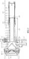
- FIG. 1 to FIG. 4are respectively a stereoscopic diagram of a trocar set in a stretched state according to a first embodiment, an exploded view of the trocar set according to the first embodiment, a cross-sectional view of the trocar set in the stretched state according to the first embodiment, and a partial, cross-sectional view of the trocar set in the stretched state according to the first embodiment.
- the trocar set 1comprises a handle portion 10, a first sleeve 20, a second sleeve 30, a gasbag 40, and a gas tight assembly 50.
- the handle portion 10comprises a grip 11, a connection part 13, a first gas valve 15, and a second gas valve 17.
- the grip 11may be, but not limited to, a semicircular shell structure of which an interior is hollow.
- the connection part 13extends from the grip 11 and is a column structure.
- the connection part 13comprises an assembling channel 131.
- the assembly channel 131is formed in a manner of penetrating through the connection part 13.
- the assembling channel 131communicates with the interior of the grip 11.
- the first gas valve 15 and the second gas valve 17may be assembled to the connection part 13.
- the first gas valve 15, the second gas valve 17, and the connection part 13may be formed in one piece, alternatively.
- gas flow channels of the first gas valve 15 and the second gas valve 17communicate with the assembling channel 131.
- the first sleeve 20comprises an assembling end 201 and a sleeving end 203.
- the assembling end 201is assembled to the assembling channel 131 of the connection part 13.
- the first sleeve 20extends from the assembling end 201 along a direction of a central axis of the assembling channel 131 and protrudes from the connection part 13.
- the first sleeve 20may be a double layer sleeve which comprises a first inner sleeve wall 21 and a first outer sleeve wall 23.
- the first sleeve 20defines a first sleeve wall region 211 and a second sleeve wall region 213.
- the first outer sleeve wall 23surrounds an exterior of the first inner sleeve wall 21 in the first sleeve wall region 211.
- the first outer sleeve wall 23does not surround the exterior of the first inner sleeve wall 21 in the second sleeve wall region 213.
- the second sleeve wall region 213is in the assembling channel 131 and corresponds to the first gas valve 15.
- the first outer sleeve wall 23 of the sleeving end 203is provided with at least one first opening 231. In other words, gas introduced from the first gas valve 15 enters the first gas flow channel 25 through a region where the first outer sleeve wall 23 does not surround the first inner sleeve wall 21 and leaves the first gas flow channel 25 from the first opening 231.
- the second sleeve 30comprises a receiving end 32.
- the sleeving end 203 of the first sleeve 20is inserted into the receiving end 32 of the second sleeve 30 such that the second sleeve 30 is retractably connected to an end of the first sleeve 20 away from the handle portion 10.
- the second sleeve 30may be a double layer sleeve which comprises a second inner sleeve wall 31 and a second outer sleeve wall 33.
- the second sleeve 30defines a third sleeve wall region 311, a fourth sleeve wall region 313, and a fifth sleeve wall region 315.
- the second outer sleeve wall 33corresponding to the sleeving end 203, surrounds an exterior of the first outer sleeve wall 23 in the third sleeve wall region 311.
- the second outer sleeve wall 33surrounds an exterior of the second inner sleeve wall 31 in the fourth sleeve wall region 313.
- the second outer sleeve wall 33does not surround the second inner sleeve wall 31 in the fifth sleeve wall region 315.
- a second gas flow channel 35is formed between the second outer sleeve wall 33 and the second inner sleeve wall 31.
- a region of the second outer sleeve wall 33 away from the sleeving end 203is provided with at least one second opening 331. Specifically, an end of the second gas flow channel 35 corresponds to the first opening 231. Gas from the first gas valve 15 is introduced through the first opening 231 and enters the second gas flow channel 35, and then leaves the second gas flow channel 35 from the second
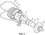
- FIG. 5 and FIG. 6are respectively a stereoscopic diagram of the trocar set in the stretched state in use according to the first embodiment and a partial, cross-sectional view of the trocar set in the stretched state in use according to the first embodiment.
- the trocar set 1 in practical useis installed with a cutlery 200.
- the cutlery 200is inserted into an opening 19 in a rear end of the handle portion 10 and is installed to the grip 11, the connection part 13, the first sleeve 20, and the second sleeve 30.
- the cutlery 200protrudes from the second sleeve 30 and is fixed to the handle portion 10 by a rear cover 210.
- the grip 11further comprises a first sealing component 117 and a second sealing component 119.
- the cutlery 200 being installedmay be assembled to and contact the first sealing component 117 and the second sealing component 119.
- the first sealing component 117 and the second sealing component 119can seal the gas flow channel such that the cutlery 200 having been fixed to the grip 11, the first sleeve 20, and the second sleeve 30 can prevent the gas from leaking to meet the gas tight ability.
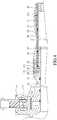
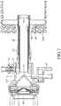
- FIG. 7 , FIG. 8 , and FIG.9are respectively a partial, cross-sectional view of the trocar set in a retracted state in use according to the first embodiment, a cross-sectional view of the trocar set in the retracted state according to the first embodiment, and a stereoscopic diagram of the trocar set in the retracted state according to the first embodiment.
- the cutlery 200can be removed from the trocar set 1 after the trocar set 1 is fixed to the human body 500 by the gasbag 40.
- the trocar set 1can be pushed forward by the handle portion 10 to have the second sleeve 30 moved towards the handle portion 10 relative to the first sleeve 20, such that the first sleeve 20 can be retracted in the second sleeve 30 to be in the retracted state. Therefore, the length of the trocar set 1 outside of the human body 500 can be significantly shortened. Additionally, when the trocar set 1 is in the retracted stated, medical professionals may conveniently put medical instruments such as an endoscope, an optical fiber, or a laser into the human body along the first sleeve 20 and the second sleeve 30 and avoid contacting the trocar set 1. Additionally, the grip 11 comprises a butting block 113 capable of fixing medical instruments such as an endoscope, an optical fiber, or a laser.
- gascan be inflated into the human body from the second gas valve 17 through the first sleeve 20 and the second sleeve 30 to have a human tissue expanded partially, which is beneficial of inserting medical instruments such as an endoscope, an optical fiber, or a laser, observing, and performing an operation.
- the second gas valve 17can be a switch of gas which may be connected to an external inflating device for inflation.
- the first gas valve 15can be turned on to have gasbag 40 deflated such that the trocar set 1 can be removed from the human body, as shown in FIG. 8 , and FIG. 9 .
- the gas tight assembly 50 of the trocar set 1is disposed on a portion where the first sleeve 20 and the second sleeve 30 are connected to each other; therefore, the portion where the first sleeve 20 and the second sleeve 30 are connected to each other can be sealed to prevent a gas leak.
- the gas tight assembly 50further comprises a blocking component 51 and a gas tight sleeve 53.
- the blocking component 51is assembled to an exterior of the first sleeve 20 and is adjacent to the sleeving end 203.
- the blocking component 51is enclosed by the gas tight sleeve 53 to prevent the first sleeve 20 from being disengaged from the second sleeve 30.
- the gas tight sleeve 53is a two piece combination. Specifically, when the trocar set 1 is in the stretched state, the first opening 231 is between the second outer sleeve wall 33 and the blocking component 51. Additionally, as shown in FIG. 7 , FIG. 8 , and FIG. 9 , when the trocar set 1 is retracted, the second sleeve 30 moves towards the handle portion 10 relative to the first sleeve 20 until the gas tight assembly 50 contacts the connection part 13.
- the gas tight assembly 50further comprises a gas tight ring 55 and a fastening component 57.
- the gas tight ring 55is connected to the exterior of the first sleeve 20.
- the gas tight sleeve 53presses the gas tight ring 55 to have the gas tight ring 55 tightly attach to the first sleeve 20 to meet the gas tight ability.
- the gas tight ring 55contacts a surface of the blocking component 51 and is enclosed by the gas tight sleeve 53. As shown in the drawing, the gas tight ring 55 is, for example, on a surface of the blocking component 51 opposing the second outer sleeve wall 33.
- the gas tight ring 55may also be disposed on a surface of the blocking component 51 facing the second outer sleeve wall 33. Alternatively, the gas tight ring(s) 55 may be disposed on both of the two surfaces of the blocking component 51.
- the fastening component 57is disposed on the sleeving end 203 of the first sleeve 20. Particularly, the fastening component 57 encloses the sleeving end 203; therefore, the height of the sleeving end 203 is slightly greater than that of other regions of the first sleeve 20.
- the fastening component 57contacts the second inner sleeve wall 31 of the second sleeve 30.
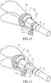
- FIG. 10 and FIG. 11are stereoscopic diagrams of a trocar set in the retracted state and in the stretched state respectively according to a second embodiment.
- a difference between the first embodiment and the second embodimentis that the trocar set 1 does not have the gasbag 40 and the first gas valve 15.
- the trocar set 1cannot be fixed to a human body by the gasbag, the trocar set 1 can be stably set by a stand or other measures after penetrating and allow instruments to be inserted there through.
- the gas tight assembly 50is connected to a portion where the first sleeve 20 and the second sleeve 30 are connected to each other.
- the gas tight assembly 50may comprise the blocking component 51 and the gas tight sleeve 53 and may further comprise the gas tight ring 55 and the fastening component 57.
Landscapes
- Health & Medical Sciences (AREA)
- Life Sciences & Earth Sciences (AREA)
- Surgery (AREA)
- Public Health (AREA)
- Animal Behavior & Ethology (AREA)
- Engineering & Computer Science (AREA)
- Biomedical Technology (AREA)
- Heart & Thoracic Surgery (AREA)
- Veterinary Medicine (AREA)
- General Health & Medical Sciences (AREA)
- Nuclear Medicine, Radiotherapy & Molecular Imaging (AREA)
- Molecular Biology (AREA)
- Medical Informatics (AREA)
- Pathology (AREA)
- Anesthesiology (AREA)
- Hematology (AREA)
- Surgical Instruments (AREA)
- Endoscopes (AREA)
Description
- The instant disclosure relates to an instrument of minimally invasive surgery and, more particularly, to a trocar set.
- In modern surgery, a trocar, instead of a surgical knife, can be used to cut an opening on a human body for a doctor to perform an operation such as burning or cutting an internal tissue by medical instruments such as an optical fiber, an endoscope, or a laser. By way of the operations, wounds caused by the operation are smaller, pains patients feel are less, time for patients' lying in bed and rest after operations is shorter, and scars are smaller. Due to the small wounds and quick recoveries, the kind of operations is called minimally invasive surgery.
- A trocar is a combination of a cutlery and a trocar set. The trocar set includes a long tube. The cutlery is fixed in the trocar set along the long tube. After the cutlery is used to cut an opening on a human body, the cutlery is removed from the long tube of the trocar set. Next, surgical instruments such as an optical fiber, an endoscope, or a laser can be inserted into the human body along the long tube to perform operations such as burning or cutting tissues.
- During an operation stage, the length of the trocar set outside the human body is longer than that inside the human body. During either an instrument inserting stage or the operation stage, it is easily happened that the medical professionals have physical contact with the trocar set outside the human body. As a result of the trocar set being contacted,
the wound may be enlarged, and patients may have greater pain intensity. Reference is made to prior art documentUS2010191050 , this document discloses a surgical accessory for guiding a flexible endoscopic tool which has a variable length. - To address the issue of prior art, the present invention provides a trocar set as defined in appended
claim 1. Preferred embodiments are defined in the appended claims. The length of the trocar outside the human body during an operation can be shortened, which is beneficial to perform the operation. The trocar set comprises a handle portion, a first sleeve, a second sleeve, and a gasbag. The handle portion comprises a grip, a connection part, and a first gas valve. The connection part extends from the grip and comprises an assembling channel. The first gas valve is connected to the connection part and communicates with the assembling channel. The first sleeve comprises an assembling end and a sleeving end. The assembling end is assembled to the assembling channel and corresponding to the first gas valve. A sleeve wall of the sleeving end is provided with at least one first opening. The second sleeve is retractably connected to the sleeving end of the first sleeve. A sleeve wall of the second sleeve is provided with at least one second opening. The gasbag is connected to an end of the second sleeve away from the first sleeve and corresponds to the second opening. The second sleeve is capable of being retracted relative to the first sleeve such that the first sleeve can be received in the second sleeve, and the total length of the first sleeve and the second sleeve can be shortened. - In an embodiment, the first sleeve further comprises a first inner sleeve wall and a first outer sleeve wall. The first sleeve defines a first sleeve wall region and a second sleeve wall region. The first outer sleeve wall surrounds an exterior of the first inner sleeve wall in the first sleeve wall region. The first outer sleeve wall does not surround the exterior of the first inner sleeve wall in the second sleeve wall region. The first opening is disposed on the first outer sleeve wall.
- Additionally, the second sleeve further comprises a second inner sleeve wall and a second outer sleeve wall. The second sleeve defines a third sleeve wall region and a fourth sleeve wall region. The second outer sleeve wall surrounds an exterior of the first outer sleeve wall in the third sleeve wall region. The second outer sleeve wall surrounds an exterior of the second inner sleeve wall in the fourth sleeve wall region. The first opening is disposed on the first outer sleeve wall, and the second opening is disposed on the second outer sleeve wall.
- Additionally, a gas flow channel is formed between the first inner sleeve wall and the first outer sleeve wall, between the first opening, the first outer sleeve wall, and the second outer sleeve wall, and between the second outer sleeve wall and the second inner sleeve wall, and communicates with the second opening. After gas flows through the first gas valve, the gas flows along the gas flow channel and enters the gasbag through the second opening to have the gasbag inflated. The trocar set can be fixed to a human body by the gasbag.
- In an embodiment, the trocar set further comprises a gas tight assembly. The gas tight assembly is disposed on a part of the first outer sleeve wall and the second outer sleeve wall and seals a portion where the first sleeve is connected to the second sleeve. In other words, the gas is restricted in the first sleeve and the second sleeve by the gas tight assembly to prevent a gas leak. Particularly, the gas inflated through the first gas valve can be restricted in the gas flow channel.
- Additionally, the gas tight assembly further comprises a blocking component and a gas tight sleeve. The blocking component is assembled to the first sleeve and is adjacent to the sleeving end. The gas tight sleeve is connected to a portion where the first sleeve is connected to the second sleeve. The gas tight sleeve encloses the blocking component. As a result, the second sleeve moves away from the handle portion when the second sleeve is stretched, and a maximum stretching length is met when the second sleeve is stretched to contact the blocking component. It can be ensured that when the second sleeve is stretched, the gas won't leak based upon the gas tight ability of the gas tight sleeve.
- Additionally, the trocar set further comprises a gas tight ring. The gas tight ring is connected to a part of the first sleeve and contacts a surface of the blocking component. The gas tight ring is enclosed by the gas tight sleeve to meet the gas tight ability.
- Additionally, the gas tight assembly further comprises a fastening component. The fastening component is assembled to the sleeving end of the first sleeve and contacts an interior of the second sleeve. As a result, the first sleeve and the second sleeve are stably connected to each other and are hard to slide so as to prevent the first sleeve and the second sleeve from disengagement.
- Additionally, when the second sleeve is retracted, the second sleeve moves towards the handle portion, the first sleeve is retracted in the second sleeve until the gas tight assembly contacts the connection part.
- In an embodiment, the grip comprises an opening. The opening communicates with the assembling channel, the first sleeve, and the second sleeve. A cutlery or another surgical instrument can be put in the trocar set through the opening and can be further fixed in the first sleeve and the second sleeve.
- In an embodiment, the trocar set further comprises a second gas valve. The second gas valve is connected to the connection part and communicates with the first sleeve. Specifically, the second gas valve provides greater amount of gas and has the gas flow into a human body to make a portion of an internal space of a human body inflated, which is beneficial of observing by an endoscope and performing an operation.
- In another embodiment, a trocar set comprises a handle portion, a second sleeve, and a gas tight assembly. The handle portion comprises a grip, a connection part, and a second gas valve. The connection part extends from the grip and comprises an assembling channel. The second gas valve is connected to the connection part and communicates with the assembling channel. The first sleeve comprises an assembling end and a sleeving end. The assembling end is assembled to the assembling channel. The second sleeve is retractably connected to the sleeving end of the first sleeve such that the second gas valve, the assembling channel, the first sleeve, and the second sleeve communicate with one another. The second sleeve can be retracted relative to the first sleeve such that the first sleeve can be received in the second sleeve, and the total length of the first sleeve and the second sleeve can be shortened. The gas tight assembly further comprises a blocking component and a gas tight sleeve. The blocking component is assembled to the first sleeve and is adjacent to the sleeving end. The gas tight sleeve is connected to a portion where the first sleeve is connected to the second sleeve. The gas tight sleeve encloses the blocking component.
- In yet another embodiment, a trocar set comprises a handle portion, a first sleeve, a second sleeve, a gas tight assembly, and a pulling band. The handle portion comprises a grip, a connection part, and a second gas valve. The connection part extends from the grip and comprises an assembling channel. The second gas valve is connected to the connection part and communicates with the assembling channel. The first sleeve comprises an assembling end and a sleeving end. The assembling end is assembled to the assembling channel. The second sleeve is retractably connected to the sleeving end of the first sleeve such that the second gas valve, the assembling channel, the first sleeve, and the second sleeve communicate with one another. The second sleeve can be retracted relative to the first sleeve such that the first sleeve can be received in the second sleeve, and the total length of the first sleeve and the second sleeve can be shortened. The gas tight assembly comprises a fastening component and a gas tight sleeve. The fastening component is assembled to the sleeving end of the first sleeve and contacts an interior of the second sleeve. The gas tight sleeve is disposed on a part of the first sleeve and the second sleeve and seals a portion where the first sleeve is connected to the second sleeve. The pulling band crosses and is fixed to a portion connected to an exterior of the gas tight sleeve. The pulling band is adjacent to the fastening component.
- According to embodiments of the trocar set of the instant disclosure, the trocar set is retractable by the connection of the first sleeve and the second sleeve. When a cutlery is removed, the length of the trocar set outside the humane body can be significantly shortened so as to avoid the trocar set outside the human body being contacted by the medical professionals. The trocar set outside the human body being contacted may make a wound enlarged. Consequently, it is benefit to medical professionals to perform operations.
FIG. 1 illustrates a stereoscopic diagram of a trocar set in a stretched state according to a first embodiment;FIG. 2 illustrates an exploded view of the trocar set according to the first embodiment;FIG. 3 illustrates a cross-sectional view of the trocar set in the stretched state according to the first embodiment;FIG. 4 illustrates a partial, cross-sectional view of the trocar set in the stretched state according to the first embodiment;FIG. 5 illustrates a stereoscopic diagram of the trocar set in the stretched state in use according to the first embodiment;FIG. 6 illustrates a cross-sectional view of the trocar set in the stretched state according to the first embodiment;FIG. 7 illustrates a partial, cross-sectional view of the trocar set in a retracted state in use according to the first embodiment;FIG. 8 illustrates a partial, cross-sectional view of the trocar set in the retracted state in use according to the first embodiment;FIG. 9 illustrates a stereoscopic diagram of the trocar set in the retracted state according to the first embodiment;FIG. 10 illustrates a stereoscopic diagram of a trocar set in the retracted state according to a second embodiment; andFIG. 11 illustrates a stereoscopic diagram of the trocar set in the stretched state according to the second embodiment.- Please refer to
FIG. 1 to FIG. 4 , which are respectively a stereoscopic diagram of a trocar set in a stretched state according to a first embodiment, an exploded view of the trocar set according to the first embodiment, a cross-sectional view of the trocar set in the stretched state according to the first embodiment, and a partial, cross-sectional view of the trocar set in the stretched state according to the first embodiment. As shown inFIG. 1 to FIG. 4 , the trocar set 1 comprises ahandle portion 10, afirst sleeve 20, asecond sleeve 30, agasbag 40, and a gastight assembly 50. Thehandle portion 10 comprises agrip 11, aconnection part 13, afirst gas valve 15, and asecond gas valve 17. Thegrip 11 may be, but not limited to, a semicircular shell structure of which an interior is hollow. Theconnection part 13 extends from thegrip 11 and is a column structure. Theconnection part 13 comprises an assemblingchannel 131. Theassembly channel 131 is formed in a manner of penetrating through theconnection part 13. The assemblingchannel 131 communicates with the interior of thegrip 11. Thefirst gas valve 15 and thesecond gas valve 17 may be assembled to theconnection part 13. Thefirst gas valve 15, thesecond gas valve 17, and theconnection part 13 may be formed in one piece, alternatively. In addition, gas flow channels of thefirst gas valve 15 and thesecond gas valve 17 communicate with the assemblingchannel 131. - The
first sleeve 20 comprises an assemblingend 201 and asleeving end 203. The assemblingend 201 is assembled to the assemblingchannel 131 of theconnection part 13. Thefirst sleeve 20 extends from the assemblingend 201 along a direction of a central axis of the assemblingchannel 131 and protrudes from theconnection part 13. Thefirst sleeve 20 may be a double layer sleeve which comprises a firstinner sleeve wall 21 and a firstouter sleeve wall 23. Specifically, thefirst sleeve 20 defines a firstsleeve wall region 211 and a secondsleeve wall region 213. The firstouter sleeve wall 23 surrounds an exterior of the firstinner sleeve wall 21 in the firstsleeve wall region 211. The firstouter sleeve wall 23 does not surround the exterior of the firstinner sleeve wall 21 in the secondsleeve wall region 213. The secondsleeve wall region 213 is in the assemblingchannel 131 and corresponds to thefirst gas valve 15. In addition, the firstouter sleeve wall 23 of thesleeving end 203 is provided with at least onefirst opening 231. In other words, gas introduced from thefirst gas valve 15 enters the firstgas flow channel 25 through a region where the firstouter sleeve wall 23 does not surround the firstinner sleeve wall 21 and leaves the firstgas flow channel 25 from thefirst opening 231. - The
second sleeve 30 comprises a receivingend 32. Thesleeving end 203 of thefirst sleeve 20 is inserted into the receivingend 32 of thesecond sleeve 30 such that thesecond sleeve 30 is retractably connected to an end of thefirst sleeve 20 away from thehandle portion 10. Thesecond sleeve 30 may be a double layer sleeve which comprises a secondinner sleeve wall 31 and a secondouter sleeve wall 33. Thesecond sleeve 30 defines a thirdsleeve wall region 311, a fourthsleeve wall region 313, and a fifthsleeve wall region 315. The secondouter sleeve wall 33, corresponding to thesleeving end 203, surrounds an exterior of the firstouter sleeve wall 23 in the thirdsleeve wall region 311. The secondouter sleeve wall 33 surrounds an exterior of the secondinner sleeve wall 31 in the fourthsleeve wall region 313. The secondouter sleeve wall 33 does not surround the secondinner sleeve wall 31 in the fifthsleeve wall region 315. A secondgas flow channel 35 is formed between the secondouter sleeve wall 33 and the secondinner sleeve wall 31. A region of the secondouter sleeve wall 33 away from thesleeving end 203 is provided with at least onesecond opening 331. Specifically, an end of the secondgas flow channel 35 corresponds to thefirst opening 231. Gas from thefirst gas valve 15 is introduced through thefirst opening 231 and enters the secondgas flow channel 35, and then leaves the secondgas flow channel 35 from thesecond opening 331. - The
gasbag 40 is connected to an end of thesecond sleeve 30 away from thefirst sleeve 20. Particularly, thegasbag 40 is connected to a part of the secondsleeve wall region 213 and connected to the thirdsleeve wall region 311. Thegasbag 40 corresponds to thesecond opening 331. In other words, the region where the firstouter sleeve wall 23 does not surround the firstinner sleeve wall 31, the firstgas flow channel 25, thefirst opening 231, the secondgas flow channel 35, and thesecond opening 331 communicate with one another to form a gas flow channel capable of inflating thegasbag 40. Gas introduced by thefirst gas valve 15 enters thegasbag 40 through the aforementioned gas flow channel to have thegasbag 40 inflated. - Please refer to
FIG. 5 andFIG. 6 , which are respectively a stereoscopic diagram of the trocar set in the stretched state in use according to the first embodiment and a partial, cross-sectional view of the trocar set in the stretched state in use according to the first embodiment. As shown inFIG. 1 to FIG. 6 , the trocar set 1 in practical use is installed with acutlery 200. Thecutlery 200 is inserted into anopening 19 in a rear end of thehandle portion 10 and is installed to thegrip 11, theconnection part 13, thefirst sleeve 20, and thesecond sleeve 30. Thecutlery 200 protrudes from thesecond sleeve 30 and is fixed to thehandle portion 10 by
arear cover 210. Additionally, thegrip 11 further comprises afirst sealing component 117 and asecond sealing component 119. Thecutlery 200 being installed may be assembled to and contact thefirst sealing component 117 and thesecond sealing component 119. Thefirst sealing component 117 and thesecond sealing component 119 can seal the gas flow channel such that thecutlery 200 having been fixed to thegrip 11, thefirst sleeve 20, and thesecond sleeve 30 can prevent the gas from leaking to meet the gas tight ability. - As shown in
FIG. 5 andFIG. 6 , after the trocar set 1 in the stretched state is used to cut an opening on ahuman body 500, gas introduced from thefirst gas valve 15 may flow through the firstgas flow channel 25, thefirst opening 231, the secondgas flow channel 35, and thesecond opening 331 and then enter thegasbag 40. When the gasbag is inflated, the trocar set 1 can be fixed in thehuman body 500. Further, thefirst gas valve 15 may be a pressing type valve, which can inflate thegasbag 40 by pressing. - Please refer to
FIG. 7 ,FIG. 8 , andFIG.9 , which are respectively a partial, cross-sectional view of the trocar set in a retracted state in use according to the first embodiment, a cross-sectional view of the trocar set in the retracted state according to the first embodiment, and a stereoscopic diagram of the trocar set in the retracted state according to the first embodiment. As shown inFIG. 7 , thecutlery 200 can be removed from the trocar set 1 after the trocar set 1 is fixed to thehuman body 500 by thegasbag 40. The trocar set 1 can be pushed forward by thehandle portion 10 to have thesecond sleeve 30 moved towards thehandle portion 10 relative to thefirst sleeve 20, such that thefirst sleeve 20 can be retracted in thesecond sleeve 30 to be in the retracted state. Therefore, the length of the trocar set 1 outside of thehuman body 500 can be significantly shortened. Additionally, when the trocar set 1 is in the retracted stated, medical professionals may conveniently put medical instruments such as an endoscope, an optical fiber, or a laser into the human body along thefirst sleeve 20 and thesecond sleeve 30 and avoid contacting the trocar set 1. Additionally, thegrip 11 comprises abutting block 113 capable of fixing medical instruments such as an endoscope, an optical fiber, or a laser. - Specifically, after the
cutlery 200 is removed, gas can be inflated into the human body from thesecond gas valve 17 through thefirst sleeve 20 and thesecond sleeve 30 to have a human tissue expanded partially, which is beneficial of inserting medical instruments such as an endoscope, an optical fiber, or a laser, observing, and performing an operation. Specifically, thesecond gas valve 17 can be a switch of gas which may be connected to an external inflating device for inflation. Additionally, after an operation is accomplished, thefirst gas valve 15 can be turned on to havegasbag 40 deflated such that the trocar set 1 can be removed from the human body, as shown inFIG. 8 , andFIG. 9 . - As shown in
FIG. 1 to FIG. 4 ., the gastight assembly 50 of the trocar set 1 is disposed on a portion where thefirst sleeve 20 and thesecond sleeve 30 are connected to each other; therefore, the portion where thefirst sleeve 20 and thesecond sleeve 30 are connected to each other can be sealed to prevent a gas leak. Specifically, the gastight assembly 50 further comprises ablocking component 51 and a gastight sleeve 53. The blockingcomponent 51 is assembled to an exterior of thefirst sleeve 20 and is adjacent to thesleeving end 203. The blockingcomponent 51 is enclosed by the gastight sleeve 53 to prevent thefirst sleeve 20 from being disengaged from thesecond sleeve 30. In an embodiment, the gastight sleeve 53 is a two piece combination. Specifically, when the trocar set 1 is in the stretched state, thefirst opening 231 is between the secondouter sleeve wall 33 and the blockingcomponent 51. Additionally, as shown inFIG. 7 ,FIG. 8 , andFIG. 9 , when the trocar set 1 is retracted, thesecond sleeve 30 moves towards thehandle portion 10 relative to thefirst sleeve 20 until the gastight assembly 50 contacts theconnection part 13. - Additionally, the gas
tight assembly 50 further comprises a gastight ring 55 and afastening component 57. The gastight ring 55 is connected to the exterior of thefirst sleeve 20. In an embodiment, the gastight sleeve 53 presses the gastight ring 55 to have the gastight ring 55 tightly attach to thefirst sleeve 20 to meet the gas tight ability. In an embodiment, the gastight ring 55 contacts a surface of the blockingcomponent 51 and is enclosed by the gas tightsleeve 53. As shown in the drawing, the gastight ring 55 is, for example, on a surface of the blockingcomponent 51 opposing the secondouter sleeve wall 33. The gastight ring 55 may also be disposed on a surface of the blockingcomponent 51 facing the secondouter sleeve wall 33. Alternatively, the gas tight ring(s) 55 may be disposed on both of the two surfaces of the blockingcomponent 51. Thefastening component 57 is disposed on thesleeving end 203 of thefirst sleeve 20. Particularly, thefastening component 57 encloses thesleeving end 203; therefore, the height of thesleeving end 203 is slightly greater than that of other regions of thefirst sleeve 20. Thefastening component 57 contacts the secondinner sleeve wall 31 of thesecond sleeve 30. Due to thefastening component 57, thesecond sleeve 30 may slide relative to thefirst sleeve 20 so as to stretch or to retract only when thesecond sleeve 30 is forced. As a result, thefirst sleeve 20 and thesecond sleeve 30 are steady after being stretched or retracted and are hard to slide so as to prevent thefirst sleeve 20 and thesecond sleeve 30 from disengagement. - Please refer to
FIG. 10 and FIG. 11 , which are stereoscopic diagrams of a trocar set in the retracted state and in the stretched state respectively according to a second embodiment. As shown inFIG. 10 and FIG. 11 , a difference between the first embodiment and the second embodiment is that the trocar set 1 does not have thegasbag 40 and thefirst gas valve 15. Although the trocar set 1 cannot be fixed to a human body by the gasbag, the trocar set 1 can be stably set by a stand or other measures after penetrating and allow instruments to be inserted there through. In order to prevent a gas leak, it is merely required that the gastight assembly 50 is connected to a portion where thefirst sleeve 20 and thesecond sleeve 30 are connected to each other. As a result, there may be no need of the structure of the double layer sleeve, and, consequently, the cost may be lower. The gastight assembly 50 may comprise the blockingcomponent 51 and the gastight sleeve 53 and may further comprise the gastight ring 55 and thefastening component 57. - Additionally, as shown in
FIG. 1 ,FIG. 5 ,FIG. 9 , andFIG. 11 , the trocar set 1 further comprises at least one pullingband 60. The pullingband 60 is at an exterior of the gastight assembly 50 and is adjacent to thefastening component 57. An outer wall of the gastight sleeve 53 is provided with two crossingchannels 531, which do not penetrate through the gastight sleeve 53. The pullingband 60 crosses the crossingchannels 531 to form a closed loop structure. When thefirst sleeve 20 is forced to be retracted in thesecond sleeve 30, and the pullingband 60 is accordingly forced towards outside, an inward force and an outward force can be balanced and then the position of thesecond sleeve 30 can be stably fixed. In an embodiment, a pulling band set comprising two pulling bands symmetric to each other may be adopted. For example, the pullingband 60 may be, but not limited to, fixed to theconnection part 13. In a state as shown inFIG. 5 , the pullingband 60 can be pulled after thegasbag 40 is inflated to make sure that the trocar set 1 is fixed to a human body. Or, the pullingband 60 may be pulled after the surgery to assist in removing the trocar set 1 from the human body. Additionally, in the first embodiment, the gasbag has to be deflated in advance such that the trocar set can be removed by the pullingband 60 after a surgery. - According to embodiments of the trocar set of the instant disclosure, the trocar set is retractable by the connection of the first sleeve and the second sleeve. When the cutlery is removed from the trocar set, the first sleeve can be retracted in the second sleeve; therefore, the length of the trocar set outside of a humane body can be significantly shortened so as to avoid the trocar set being unintentionally contacted by medical professionals. A trocar set outside of the humane body being contacted may cause pain and make a wound enlarged. Consequently, it is benefit to medical professionals to insert instruments and perform operations.
- While the instant disclosure has been described by way of example and in terms of the preferred embodiments, it is to be understood that the instant disclosure needs not be limited to the disclosed embodiments. For anyone skilled in the art, various modifications and improvements are covered under the scope of the instant disclosure. The covered scope of the instant disclosure is based on the appended claims.
Claims (3)
- A trocar set(1),the trocar set (1) comprising:a handle portion (10) comprising a grip (11), a connection part (13), and a gas valve (17), wherein the connection part (13) extends from the grip (11) and comprises an assembling channel (131), and the gas valve (17) is connected to the connection part (13) and communicates with the assembling channel (131);a first sleeve (20) comprising an assembling end (201), a sleeving end (203), a first outer sleeve wall (23), and a fastening component (57), wherein the assembling end (201) is assembled to the assembling channel (131), and the fastening component (57) is disposed at the sleeving end (203) and contacts the first outer sleeve wall (23);a second sleeve (30) comprising a receiving end (32) and a second inner sleeve wall (31), wherein the sleeving end (203) is inserted into the receiving end (32), and the second inner sleeve wall (31) contacts the fastening component (57);a gas tight assembly (50) comprising a gas tight sleeve (53) and a blocking component (51), wherein the gas tight sleeve (53) is fixed to the second sleeve (30) and encloses the receiving end (32) and the blocking component (51), the blocking component (51) restricts an axial displacement of the gas tight sleeve (53) such that the first sleeve (20) cannot be disengaged from the second sleeve (30), and an outer wall of the gas tight sleeve (53) is provided with a plurality of crossing channels (531) and the crossing channels (531) are not in a through-hole type; anda pulling band (60) crossing the crossing channel (531).
- The trocar set of claim 1, wherein the pulling band (60) is configured to be forced towards outside to fix the second sleeve (30) while the first sleeve (20) is configured to be forced to be retracted in the second sleeve (30).
- The trocar set of claim 2, further comprising a gas tight ring (55), the gas tight ring being connected to a part of the first sleeve (20) and being adjacent to the blocking component (51).
Applications Claiming Priority (1)
| Application Number | Priority Date | Filing Date | Title |
|---|---|---|---|
| TW105139683ATWI630899B (en) | 2016-12-01 | 2016-12-01 | Trocar housing |
Publications (2)
| Publication Number | Publication Date |
|---|---|
| EP3329867A1 EP3329867A1 (en) | 2018-06-06 |
| EP3329867B1true EP3329867B1 (en) | 2019-06-12 |
Family
ID=58606108
Family Applications (3)
| Application Number | Title | Priority Date | Filing Date |
|---|---|---|---|
| EP17167528.3AActiveEP3329869B1 (en) | 2016-12-01 | 2017-04-21 | Collapsible trocar |
| EP17167524.2AActiveEP3329868B1 (en) | 2016-12-01 | 2017-04-21 | Trocar set with distal gas bag |
| EP17167491.4AActiveEP3329867B1 (en) | 2016-12-01 | 2017-04-21 | Collapsible trocar |
Family Applications Before (2)
| Application Number | Title | Priority Date | Filing Date |
|---|---|---|---|
| EP17167528.3AActiveEP3329869B1 (en) | 2016-12-01 | 2017-04-21 | Collapsible trocar |
| EP17167524.2AActiveEP3329868B1 (en) | 2016-12-01 | 2017-04-21 | Trocar set with distal gas bag |
Country Status (5)
| Country | Link |
|---|---|
| US (4) | US20180153537A1 (en) |
| EP (3) | EP3329869B1 (en) |
| JP (1) | JP6317836B1 (en) |
| CN (1) | CN108125706A (en) |
| TW (1) | TWI630899B (en) |
Families Citing this family (5)
| Publication number | Priority date | Publication date | Assignee | Title |
|---|---|---|---|---|
| CA3015089A1 (en)* | 2017-08-23 | 2019-02-23 | Memic Innovative Surgery Ltd. | Tools and methods for vaginal access |
| CN109793555A (en)* | 2017-11-17 | 2019-05-24 | 英济股份有限公司 | puncture |
| CN109124738B (en)* | 2018-08-28 | 2021-02-09 | 浙江天松医疗器械股份有限公司 | Puncture outfit casing pipe and use method of inner pipe and outer pipe thereof |
| RU199577U1 (en)* | 2020-03-12 | 2020-09-08 | Казбек Меджидович Аутлев | Telescopic trocar |
| CN111904599A (en)* | 2020-09-18 | 2020-11-10 | 象山县第一人民医院医疗健康集团 | Mechanical arm for thoracoscope |
Family Cites Families (28)
| Publication number | Priority date | Publication date | Assignee | Title |
|---|---|---|---|---|
| JPS4523221Y1 (en)* | 1967-03-25 | 1970-09-12 | ||
| US3856020A (en)* | 1973-09-17 | 1974-12-24 | S Kovac | Trocar-catheter assembly |
| US5407427A (en)* | 1992-06-16 | 1995-04-18 | Loma Linda University Medical Center | Trocar facilitator for endoscopic surgery |
| AU7743494A (en)* | 1993-10-26 | 1995-05-18 | Ethicon Endo-Surgery, Inc. | Trocar with a retractable cannula |
| US5591194A (en)* | 1994-02-18 | 1997-01-07 | C. R. Bard, Inc. | Telescoping balloon catheter and method of use |
| US5505710A (en)* | 1994-08-22 | 1996-04-09 | C. R. Bard, Inc. | Telescoping probe |
| US5957888A (en)* | 1995-10-10 | 1999-09-28 | United States Surgical Corporation | Surgical cannula having a variable length |
| US5882344A (en)* | 1995-10-18 | 1999-03-16 | Stouder, Jr.; Albert E. | Adjustable length cannula and trocar |
| US6197002B1 (en)* | 1997-12-10 | 2001-03-06 | Phillips Plastics Corporation | Laparoscopic tool and method |
| JP2003061970A (en)* | 2001-08-23 | 2003-03-04 | Olympus Optical Co Ltd | Trocar mantle tube |
| US20050096507A1 (en)* | 2003-10-30 | 2005-05-05 | Prosek Michael U. | Adjustable length cannula |
| JP3864344B2 (en)* | 2003-12-05 | 2006-12-27 | フジノン株式会社 | Endoscope insertion aid |
| US7087053B2 (en)* | 2004-05-27 | 2006-08-08 | St. Jude Medical, Atrial Fibrillation Division, Inc. | Catheter with bifurcated, collapsible tip for sensing and ablating |
| US20070162066A1 (en)* | 2006-01-10 | 2007-07-12 | Lyon Thomas R | Clear view cannula |
| KR20090015073A (en)* | 2006-04-21 | 2009-02-11 | 인터벤셔널 스파인, 인코포레이티드 | Methods and instruments for spinal fixation |
| US20090204067A1 (en)* | 2008-02-07 | 2009-08-13 | Mohamed Saad Abu-Halawa | Two-part percutaneous endoscopic intragastric surgery cannula |
| US7828775B2 (en)* | 2008-04-11 | 2010-11-09 | Tyco Healthcare Group Lp | Telescoping cannula |
| US7833200B2 (en)* | 2008-06-27 | 2010-11-16 | Tyco Healthcare Group Lp | Trocar assembly with radially moveable housing |
| US20100191050A1 (en)* | 2009-01-23 | 2010-07-29 | Ethicon Endo-Surgery, Inc. | Variable length accessory for guiding a flexible endoscopic tool |
| TWM393288U (en)* | 2010-03-16 | 2010-12-01 | Po-Yi Wang | Bladeless trocar |
| EP2614780B1 (en)* | 2010-09-10 | 2017-10-25 | Seo, O Nam | Endoscopy instrument guider port |
| EP2615980B1 (en)* | 2010-09-19 | 2017-08-16 | EON Surgical Ltd. | Micro laparoscopy devices and deployments thereof |
| US10603073B2 (en)* | 2011-05-31 | 2020-03-31 | Karl Storz Se & Co. Kg | Trocar sleeve |
| US8439881B2 (en)* | 2011-08-25 | 2013-05-14 | Ethicon Endo-Surgery, Inc. | Surgical access device with adjustable cannula |
| JP5938183B2 (en)* | 2011-09-22 | 2016-06-22 | 積水化学工業株式会社 | Expansion joint structure |
| TWM474472U (en)* | 2013-10-07 | 2014-03-21 | Prec Machinery Res & Dev Ct | Visible trocar |
| CN105030306B (en)* | 2015-04-09 | 2017-06-06 | 徐成学 | Puncture outfit |
| TWM541310U (en)* | 2016-12-01 | 2017-05-11 | 英濟股份有限公司 | Puncture kit |
- 2016
- 2016-12-01TWTW105139683Apatent/TWI630899B/ennot_activeIP Right Cessation
- 2016-12-07CNCN201611114595.9Apatent/CN108125706A/ennot_activeWithdrawn
- 2017
- 2017-04-17JPJP2017081286Apatent/JP6317836B1/ennot_activeExpired - Fee Related
- 2017-04-21EPEP17167528.3Apatent/EP3329869B1/enactiveActive
- 2017-04-21EPEP17167524.2Apatent/EP3329868B1/enactiveActive
- 2017-04-21EPEP17167491.4Apatent/EP3329867B1/enactiveActive
- 2017-04-25USUS15/496,851patent/US20180153537A1/ennot_activeAbandoned
- 2017-04-25USUS15/496,810patent/US10188424B2/ennot_activeExpired - Fee Related
- 2017-04-25USUS15/496,831patent/US10278731B2/enactiveActive
- 2019
- 2019-01-23USUS16/255,005patent/US20190150977A1/ennot_activeAbandoned
Non-Patent Citations (1)
| Title |
|---|
| None* |
Also Published As
| Publication number | Publication date |
|---|---|
| JP6259942B1 (en) | 2018-01-10 |
| US10278731B2 (en) | 2019-05-07 |
| TWI630899B (en) | 2018-08-01 |
| EP3329869A1 (en) | 2018-06-06 |
| JP6317836B1 (en) | 2018-04-25 |
| EP3329868B1 (en) | 2019-06-12 |
| US20180154091A1 (en) | 2018-06-07 |
| JP6259941B1 (en) | 2018-01-10 |
| EP3329869B1 (en) | 2019-06-12 |
| EP3329868A1 (en) | 2018-06-06 |
| CN108125706A (en) | 2018-06-08 |
| JP2018089330A (en) | 2018-06-14 |
| US20190150977A1 (en) | 2019-05-23 |
| US20180153537A1 (en) | 2018-06-07 |
| TW201821037A (en) | 2018-06-16 |
| JP2018089332A (en) | 2018-06-14 |
| EP3329867A1 (en) | 2018-06-06 |
| JP2018089331A (en) | 2018-06-14 |
| US20180153580A1 (en) | 2018-06-07 |
| US10188424B2 (en) | 2019-01-29 |
Similar Documents
| Publication | Publication Date | Title |
|---|---|---|
| EP3329867B1 (en) | Collapsible trocar | |
| US9220396B2 (en) | Balloon access device for endoscope | |
| US10786280B2 (en) | Trocar | |
| JP4594612B2 (en) | Insertion aid | |
| US9833126B2 (en) | Balloon access device with features for engaging an endoscope | |
| IE991014A1 (en) | A Device | |
| KR102293147B1 (en) | Wound Retractor for Laparoscopic Surgery | |
| TWI644646B (en) | Puncture device | |
| CN206777383U (en) | Puncture outfit set | |
| JP5989411B2 (en) | Laparoscopic device | |
| KR101642601B1 (en) | Trocar for laparoscope | |
| TWM559722U (en) | Puncture device | |
| JP6259941B6 (en) | Trocar assembly | |
| JP6259942B6 (en) | Trocar assembly | |
| JP4083296B2 (en) | Percutaneous tissue layer peeling device | |
| EP3079558A1 (en) | Balloon access device with features for engaging an endoscope | |
| JP2014140509A (en) | Trocar for endoscopic operation and endoscopic operation system using trocar |
Legal Events
| Date | Code | Title | Description |
|---|---|---|---|
| PUAI | Public reference made under article 153(3) epc to a published international application that has entered the european phase | Free format text:ORIGINAL CODE: 0009012 | |
| STAA | Information on the status of an ep patent application or granted ep patent | Free format text:STATUS: THE APPLICATION HAS BEEN PUBLISHED | |
| AK | Designated contracting states | Kind code of ref document:A1 Designated state(s):AL AT BE BG CH CY CZ DE DK EE ES FI FR GB GR HR HU IE IS IT LI LT LU LV MC MK MT NL NO PL PT RO RS SE SI SK SM TR | |
| AX | Request for extension of the european patent | Extension state:BA ME | |
| STAA | Information on the status of an ep patent application or granted ep patent | Free format text:STATUS: REQUEST FOR EXAMINATION WAS MADE | |
| 17P | Request for examination filed | Effective date:20180702 | |
| RBV | Designated contracting states (corrected) | Designated state(s):AL AT BE BG CH CY CZ DE DK EE ES FI FR GB GR HR HU IE IS IT LI LT LU LV MC MK MT NL NO PL PT RO RS SE SI SK SM TR | |
| GRAP | Despatch of communication of intention to grant a patent | Free format text:ORIGINAL CODE: EPIDOSNIGR1 | |
| STAA | Information on the status of an ep patent application or granted ep patent | Free format text:STATUS: GRANT OF PATENT IS INTENDED | |
| INTG | Intention to grant announced | Effective date:20181210 | |
| GRAS | Grant fee paid | Free format text:ORIGINAL CODE: EPIDOSNIGR3 | |
| GRAA | (expected) grant | Free format text:ORIGINAL CODE: 0009210 | |
| STAA | Information on the status of an ep patent application or granted ep patent | Free format text:STATUS: THE PATENT HAS BEEN GRANTED | |
| RAP1 | Party data changed (applicant data changed or rights of an application transferred) | Owner name:COREBIO TECHNOLOGIES CO., LTD. Owner name:MEGAFORCE COMPANY LIMITED | |
| AK | Designated contracting states | Kind code of ref document:B1 Designated state(s):AL AT BE BG CH CY CZ DE DK EE ES FI FR GB GR HR HU IE IS IT LI LT LU LV MC MK MT NL NO PL PT RO RS SE SI SK SM TR | |
| REG | Reference to a national code | Ref country code:GB Ref legal event code:FG4D | |
| REG | Reference to a national code | Ref country code:CH Ref legal event code:EP | |
| REG | Reference to a national code | Ref country code:AT Ref legal event code:REF Ref document number:1141565 Country of ref document:AT Kind code of ref document:T Effective date:20190615 | |
| REG | Reference to a national code | Ref country code:DE Ref legal event code:R096 Ref document number:602017004403 Country of ref document:DE | |
| REG | Reference to a national code | Ref country code:IE Ref legal event code:FG4D | |
| REG | Reference to a national code | Ref country code:NL Ref legal event code:MP Effective date:20190612 | |
| REG | Reference to a national code | Ref country code:LT Ref legal event code:MG4D | |
| PG25 | Lapsed in a contracting state [announced via postgrant information from national office to epo] | Ref country code:FI Free format text:LAPSE BECAUSE OF FAILURE TO SUBMIT A TRANSLATION OF THE DESCRIPTION OR TO PAY THE FEE WITHIN THE PRESCRIBED TIME-LIMIT Effective date:20190612 Ref country code:SE Free format text:LAPSE BECAUSE OF FAILURE TO SUBMIT A TRANSLATION OF THE DESCRIPTION OR TO PAY THE FEE WITHIN THE PRESCRIBED TIME-LIMIT Effective date:20190612 Ref country code:LT Free format text:LAPSE BECAUSE OF FAILURE TO SUBMIT A TRANSLATION OF THE DESCRIPTION OR TO PAY THE FEE WITHIN THE PRESCRIBED TIME-LIMIT Effective date:20190612 Ref country code:AL Free format text:LAPSE BECAUSE OF FAILURE TO SUBMIT A TRANSLATION OF THE DESCRIPTION OR TO PAY THE FEE WITHIN THE PRESCRIBED TIME-LIMIT Effective date:20190612 Ref country code:NO Free format text:LAPSE BECAUSE OF FAILURE TO SUBMIT A TRANSLATION OF THE DESCRIPTION OR TO PAY THE FEE WITHIN THE PRESCRIBED TIME-LIMIT Effective date:20190912 Ref country code:HR Free format text:LAPSE BECAUSE OF FAILURE TO SUBMIT A TRANSLATION OF THE DESCRIPTION OR TO PAY THE FEE WITHIN THE PRESCRIBED TIME-LIMIT Effective date:20190612 | |
| PG25 | Lapsed in a contracting state [announced via postgrant information from national office to epo] | Ref country code:LV Free format text:LAPSE BECAUSE OF FAILURE TO SUBMIT A TRANSLATION OF THE DESCRIPTION OR TO PAY THE FEE WITHIN THE PRESCRIBED TIME-LIMIT Effective date:20190612 Ref country code:GR Free format text:LAPSE BECAUSE OF FAILURE TO SUBMIT A TRANSLATION OF THE DESCRIPTION OR TO PAY THE FEE WITHIN THE PRESCRIBED TIME-LIMIT Effective date:20190913 Ref country code:BG Free format text:LAPSE BECAUSE OF FAILURE TO SUBMIT A TRANSLATION OF THE DESCRIPTION OR TO PAY THE FEE WITHIN THE PRESCRIBED TIME-LIMIT Effective date:20190912 Ref country code:RS Free format text:LAPSE BECAUSE OF FAILURE TO SUBMIT A TRANSLATION OF THE DESCRIPTION OR TO PAY THE FEE WITHIN THE PRESCRIBED TIME-LIMIT Effective date:20190612 | |
| REG | Reference to a national code | Ref country code:AT Ref legal event code:MK05 Ref document number:1141565 Country of ref document:AT Kind code of ref document:T Effective date:20190612 | |
| PG25 | Lapsed in a contracting state [announced via postgrant information from national office to epo] | Ref country code:PT Free format text:LAPSE BECAUSE OF FAILURE TO SUBMIT A TRANSLATION OF THE DESCRIPTION OR TO PAY THE FEE WITHIN THE PRESCRIBED TIME-LIMIT Effective date:20191014 Ref country code:RO Free format text:LAPSE BECAUSE OF FAILURE TO SUBMIT A TRANSLATION OF THE DESCRIPTION OR TO PAY THE FEE WITHIN THE PRESCRIBED TIME-LIMIT Effective date:20190612 Ref country code:NL Free format text:LAPSE BECAUSE OF FAILURE TO SUBMIT A TRANSLATION OF THE DESCRIPTION OR TO PAY THE FEE WITHIN THE PRESCRIBED TIME-LIMIT Effective date:20190612 Ref country code:CZ Free format text:LAPSE BECAUSE OF FAILURE TO SUBMIT A TRANSLATION OF THE DESCRIPTION OR TO PAY THE FEE WITHIN THE PRESCRIBED TIME-LIMIT Effective date:20190612 Ref country code:AT Free format text:LAPSE BECAUSE OF FAILURE TO SUBMIT A TRANSLATION OF THE DESCRIPTION OR TO PAY THE FEE WITHIN THE PRESCRIBED TIME-LIMIT Effective date:20190612 Ref country code:EE Free format text:LAPSE BECAUSE OF FAILURE TO SUBMIT A TRANSLATION OF THE DESCRIPTION OR TO PAY THE FEE WITHIN THE PRESCRIBED TIME-LIMIT Effective date:20190612 Ref country code:SK Free format text:LAPSE BECAUSE OF FAILURE TO SUBMIT A TRANSLATION OF THE DESCRIPTION OR TO PAY THE FEE WITHIN THE PRESCRIBED TIME-LIMIT Effective date:20190612 | |
| PG25 | Lapsed in a contracting state [announced via postgrant information from national office to epo] | Ref country code:SM Free format text:LAPSE BECAUSE OF FAILURE TO SUBMIT A TRANSLATION OF THE DESCRIPTION OR TO PAY THE FEE WITHIN THE PRESCRIBED TIME-LIMIT Effective date:20190612 Ref country code:IT Free format text:LAPSE BECAUSE OF FAILURE TO SUBMIT A TRANSLATION OF THE DESCRIPTION OR TO PAY THE FEE WITHIN THE PRESCRIBED TIME-LIMIT Effective date:20190612 Ref country code:IS Free format text:LAPSE BECAUSE OF FAILURE TO SUBMIT A TRANSLATION OF THE DESCRIPTION OR TO PAY THE FEE WITHIN THE PRESCRIBED TIME-LIMIT Effective date:20191012 Ref country code:ES Free format text:LAPSE BECAUSE OF FAILURE TO SUBMIT A TRANSLATION OF THE DESCRIPTION OR TO PAY THE FEE WITHIN THE PRESCRIBED TIME-LIMIT Effective date:20190612 | |
| REG | Reference to a national code | Ref country code:DE Ref legal event code:R097 Ref document number:602017004403 Country of ref document:DE | |
| PG25 | Lapsed in a contracting state [announced via postgrant information from national office to epo] | Ref country code:TR Free format text:LAPSE BECAUSE OF FAILURE TO SUBMIT A TRANSLATION OF THE DESCRIPTION OR TO PAY THE FEE WITHIN THE PRESCRIBED TIME-LIMIT Effective date:20190612 | |
| PLBE | No opposition filed within time limit | Free format text:ORIGINAL CODE: 0009261 | |
| STAA | Information on the status of an ep patent application or granted ep patent | Free format text:STATUS: NO OPPOSITION FILED WITHIN TIME LIMIT | |
| PG25 | Lapsed in a contracting state [announced via postgrant information from national office to epo] | Ref country code:DK Free format text:LAPSE BECAUSE OF FAILURE TO SUBMIT A TRANSLATION OF THE DESCRIPTION OR TO PAY THE FEE WITHIN THE PRESCRIBED TIME-LIMIT Effective date:20190612 Ref country code:PL Free format text:LAPSE BECAUSE OF FAILURE TO SUBMIT A TRANSLATION OF THE DESCRIPTION OR TO PAY THE FEE WITHIN THE PRESCRIBED TIME-LIMIT Effective date:20190612 | |
| 26N | No opposition filed | Effective date:20200313 | |
| PG25 | Lapsed in a contracting state [announced via postgrant information from national office to epo] | Ref country code:SI Free format text:LAPSE BECAUSE OF FAILURE TO SUBMIT A TRANSLATION OF THE DESCRIPTION OR TO PAY THE FEE WITHIN THE PRESCRIBED TIME-LIMIT Effective date:20190612 Ref country code:IS Free format text:LAPSE BECAUSE OF FAILURE TO SUBMIT A TRANSLATION OF THE DESCRIPTION OR TO PAY THE FEE WITHIN THE PRESCRIBED TIME-LIMIT Effective date:20200224 | |
| PG2D | Information on lapse in contracting state deleted | Ref country code:IS | |
| PG25 | Lapsed in a contracting state [announced via postgrant information from national office to epo] | Ref country code:MC Free format text:LAPSE BECAUSE OF FAILURE TO SUBMIT A TRANSLATION OF THE DESCRIPTION OR TO PAY THE FEE WITHIN THE PRESCRIBED TIME-LIMIT Effective date:20190612 | |
| REG | Reference to a national code | Ref country code:CH Ref legal event code:PL | |
| PG25 | Lapsed in a contracting state [announced via postgrant information from national office to epo] | Ref country code:CH Free format text:LAPSE BECAUSE OF NON-PAYMENT OF DUE FEES Effective date:20200430 Ref country code:LU Free format text:LAPSE BECAUSE OF NON-PAYMENT OF DUE FEES Effective date:20200421 Ref country code:LI Free format text:LAPSE BECAUSE OF NON-PAYMENT OF DUE FEES Effective date:20200430 | |
| REG | Reference to a national code | Ref country code:BE Ref legal event code:MM Effective date:20200430 | |
| PG25 | Lapsed in a contracting state [announced via postgrant information from national office to epo] | Ref country code:BE Free format text:LAPSE BECAUSE OF NON-PAYMENT OF DUE FEES Effective date:20200430 | |
| PG25 | Lapsed in a contracting state [announced via postgrant information from national office to epo] | Ref country code:IE Free format text:LAPSE BECAUSE OF NON-PAYMENT OF DUE FEES Effective date:20200421 | |
| PGFP | Annual fee paid to national office [announced via postgrant information from national office to epo] | Ref country code:FR Payment date:20210128 Year of fee payment:5 | |
| PGFP | Annual fee paid to national office [announced via postgrant information from national office to epo] | Ref country code:GB Payment date:20210202 Year of fee payment:5 | |
| PGFP | Annual fee paid to national office [announced via postgrant information from national office to epo] | Ref country code:DE Payment date:20210129 Year of fee payment:5 | |
| PG25 | Lapsed in a contracting state [announced via postgrant information from national office to epo] | Ref country code:MT Free format text:LAPSE BECAUSE OF FAILURE TO SUBMIT A TRANSLATION OF THE DESCRIPTION OR TO PAY THE FEE WITHIN THE PRESCRIBED TIME-LIMIT Effective date:20190612 Ref country code:CY Free format text:LAPSE BECAUSE OF FAILURE TO SUBMIT A TRANSLATION OF THE DESCRIPTION OR TO PAY THE FEE WITHIN THE PRESCRIBED TIME-LIMIT Effective date:20190612 | |
| PG25 | Lapsed in a contracting state [announced via postgrant information from national office to epo] | Ref country code:MK Free format text:LAPSE BECAUSE OF FAILURE TO SUBMIT A TRANSLATION OF THE DESCRIPTION OR TO PAY THE FEE WITHIN THE PRESCRIBED TIME-LIMIT Effective date:20190612 | |
| REG | Reference to a national code | Ref country code:DE Ref legal event code:R119 Ref document number:602017004403 Country of ref document:DE | |
| GBPC | Gb: european patent ceased through non-payment of renewal fee | Effective date:20220421 | |
| PG25 | Lapsed in a contracting state [announced via postgrant information from national office to epo] | Ref country code:GB Free format text:LAPSE BECAUSE OF NON-PAYMENT OF DUE FEES Effective date:20220421 Ref country code:FR Free format text:LAPSE BECAUSE OF NON-PAYMENT OF DUE FEES Effective date:20220430 Ref country code:DE Free format text:LAPSE BECAUSE OF NON-PAYMENT OF DUE FEES Effective date:20221103 |