EP3329606B1 - Receive beam indication for 5g systems - Google Patents
Receive beam indication for 5g systemsDownload PDFInfo
- Publication number
- EP3329606B1 EP3329606B1EP15828796.1AEP15828796AEP3329606B1EP 3329606 B1EP3329606 B1EP 3329606B1EP 15828796 AEP15828796 AEP 15828796AEP 3329606 B1EP3329606 B1EP 3329606B1
- Authority
- EP
- European Patent Office
- Prior art keywords
- epdcch
- circuitry
- layer
- processors
- pdsch
- Prior art date
- Legal status (The legal status is an assumption and is not a legal conclusion. Google has not performed a legal analysis and makes no representation as to the accuracy of the status listed.)
- Active
Links
Images


Classifications
- H—ELECTRICITY
- H04—ELECTRIC COMMUNICATION TECHNIQUE
- H04B—TRANSMISSION
- H04B7/00—Radio transmission systems, i.e. using radiation field
- H04B7/02—Diversity systems; Multi-antenna system, i.e. transmission or reception using multiple antennas
- H04B7/04—Diversity systems; Multi-antenna system, i.e. transmission or reception using multiple antennas using two or more spaced independent antennas
- H04B7/08—Diversity systems; Multi-antenna system, i.e. transmission or reception using multiple antennas using two or more spaced independent antennas at the receiving station
- H04B7/0868—Hybrid systems, i.e. switching and combining
- H04B7/088—Hybrid systems, i.e. switching and combining using beam selection
- H—ELECTRICITY
- H04—ELECTRIC COMMUNICATION TECHNIQUE
- H04B—TRANSMISSION
- H04B7/00—Radio transmission systems, i.e. using radiation field
- H04B7/02—Diversity systems; Multi-antenna system, i.e. transmission or reception using multiple antennas
- H04B7/022—Site diversity; Macro-diversity
- H04B7/024—Co-operative use of antennas of several sites, e.g. in co-ordinated multipoint or co-operative multiple-input multiple-output [MIMO] systems
- H—ELECTRICITY
- H04—ELECTRIC COMMUNICATION TECHNIQUE
- H04B—TRANSMISSION
- H04B7/00—Radio transmission systems, i.e. using radiation field
- H04B7/02—Diversity systems; Multi-antenna system, i.e. transmission or reception using multiple antennas
- H04B7/04—Diversity systems; Multi-antenna system, i.e. transmission or reception using multiple antennas using two or more spaced independent antennas
- H04B7/08—Diversity systems; Multi-antenna system, i.e. transmission or reception using multiple antennas using two or more spaced independent antennas at the receiving station
- H04B7/0837—Diversity systems; Multi-antenna system, i.e. transmission or reception using multiple antennas using two or more spaced independent antennas at the receiving station using pre-detection combining
- H04B7/0842—Weighted combining
- H04B7/0862—Weighted combining receiver computing weights based on information from the transmitter
Definitions
- Wireless mobile communication technologyuses various standards and protocols to transmit data between a node (e.g., a transmission station) and a wireless device (e.g., a mobile device).
- Some wireless devicescommunicate using orthogonal frequency-division multiple access (OFDMA) in a downlink (DL) transmission and single carrier frequency division multiple access (SC-FDMA) in an uplink (UL) transmission.
- OFDMAorthogonal frequency-division multiple access
- SC-FDMAsingle carrier frequency division multiple access
- OFDMorthogonal frequency-division multiplexing
- 3GPPthird generation partnership project
- LTElong term evolution
- IEEEInstitute of Electrical and Electronics Engineers
- 802.16 standarde.g., 802.16e, 802.16m
- WiMAXWorldwide Interoperability for Microwave Access
- IEEE 802.11which is commonly known to industry groups as WiFi.
- the node in an Evolved Universal Terrestrial Radio Access Network (E-UTRAN) systemis referred to as an eNode B (also commonly denoted as evolved Node Bs, enhanced Node Bs, eNodeBs, or eNBs), which communicates with the wireless device, known as a user equipment (UE).
- the downlink (DL) transmissioncan be a communication from the node (e.g., eNodeB) to the wireless device (e.g., UE), and the uplink (UL) transmission can be a communication from the wireless device to the node.
- datacan be transmitted from the eNodeB to the UE via a physical downlink shared channel (PDSCH).
- PDSCHphysical downlink shared channel
- a physical uplink control channel (PUCCH)can be used to acknowledge that data was received.
- Downlink and uplink channels or transmissionscan use time-division duplexing (TDD) or frequency-division duplexing (FDD).
- TDDtime-division duplexing
- FDDfrequency-division duplexing
- DPSDynamic point selection
- CoMPCoordinated multipoint
- JTjoint transmission
- CS/CBcooperative scheduling/cooperative beamforming
- US 2013/223251 A1discloses a method for beam selection, where a mobile station identifies beamforming constraints of the mobile station, performs a measurement on a channel between a base station and the mobile device on at least one transmit beam and at least one receive beam and sending beam forming feedback information based on the identified constraints of the mobile station and the channel measurement.
- US 2013/223251 A1further discloses a method to be performed by a base station including receiving the beamforming feedback information and sending to the mobile station control information comprising an indication of at least one mobile device receive beam and at least one base station transmit beam to be used for downlink.
- Downlink Coordinated Multipointcan be used to improve throughput performance for a user equipment (UE) located at a cell edge.
- the throughput improvement in DL CoMPcan be achieved by coordinating which of a plurality neighboring of neighboring transmission points will transmit certain DL information to the UE at a given time (e.g., by using dynamic point selection (DPS) CoMP).
- DPSdynamic point selection
- FIG.illustrates a network diagram 100 that provides an example of a setting in which DPS CoMP can be used so that a transmission point (TP) can be dynamically selected for a user equipment (UE) 106 based on instantaneous channel/interference conditions and based on cell traffic loads.
- the UE 106can receive downlink (DL) control data from a serving cellular base station 102.
- the UE 106can also receive a Physical Downlink Shared Channel (PDSCH) transmission from either the serving cellular base station 102 or a second non-serving cellular base station 104.
- DLdownlink
- PDSCHPhysical Downlink Shared Channel
- FIG. 1cellular base stations 102 and 104 are shown in FIG. 1 , other types of TPs may also be used in other examples.
- Quasi co-location and PDSCH Resource Element (RE) mapping signalingcan be used to indicate a set of reference signals (antenna ports) for time and frequency synchronization with a TP (e.g., cellular base station 102 or cellular base station 104).
- the quasi co-location and PDSCH RE mapping signalingcan also be used to indicate REs on which the PDSCH will be transmitted from the TP (e.g., cellular base station 102 or cellular base station 104).
- Up to four PDSCH RE mapping and quasi co-location setscan be configured for the UE using higher-layer signaling.
- One of the four PDSCH RE mapping and quasi co-location setscan be indicated in Downlink Control Information (DCI) using a '2-bit PDSCH RE mapping and quasi-co-location' field.
- DCIDownlink Control Information
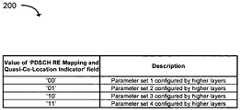
- FIG. 2illustrates an example table of two-bit values and indices of their corresponding parameter sets (e.g., PDSCH RE mapping and quasi co-location sets).
- a two-bit value of 00can indicate that a first parameter set should be used by the UE, while a two-bit value of 01 can indicate that a second parameter set should be used, a two-bit value of 10 can indicate that a third parameter set should be used, and a two-bit value of 11 can indicate that a fourth parameter set should be used.
- a PDSCH RE mapping and quasi co-location setcan include a number of parameters that determine PDSCH RE mapping and PDSCH antenna port quasi-co-location, such as: 'number of Common Reference Signal (CRS) antenna ports for 'Number of CRS antenna ports for PDSCH RE mapping,' 'Multicast-Broadcast Single-Frequency Network (MBSFN) subframe configuration for PDSCH RE mapping,' 'Zero-power Channel State Information Reference Signal (CSI-RS) resource configuration for PDSCH RE mapping,' 'PDSCH starting position for PDSCH RE mapping,' and 'CSI-RS resource configuration identity for quasi co-location.
- CRSCommon Reference Signal
- MMSFNMulticast-Broadcast Single-Frequency Network
- CSI-RSChannel State Information Reference Signal
- receiver antenna weightsare dynamically adapted (after analog-to-digital conversion) on a Physical Resource Block (PRB) basis using UE-specific reference signals that are transmitted with the same precoding as the PDSCH.
- PDCCHPhysical Downlink Control Channel
- PRBPhysical Resource Block
- each antenna elementmay be connected to one transceiver unit (TXRU) as in existing LTE-A systems, wherein a TXRU typically comprises a Radio Frequency (RF) unit and an Analog-to-Digital Converter (ADC).
- TXRUtransceiver unit
- RFRadio Frequency
- ADCAnalog-to-Digital Converter
- a TXRUcan be connected to one or more antenna elements using phase shifters (and potentially attenuators) to allow adaptive control of antenna beamforming in the RF domain (i.e., before analog-to-digital conversion).
- FIG. 3illustrates an example of a TXRU-to-antenna connection model 300.
- Complex weights 304a-dcan be used to rotate the phase of a signal or control the amplitude of signals received from antenna elements 306a-d, respectively.
- a subarray 308can comprise the antenna elements 306a-d.
- complex weights 314a ⁇ dcan be used to rotate the phase of a signal or control the amplitude of signals received from antenna elements 316a ⁇ d, respectively.
- a subarray 318can comprise the antenna elements 316a ⁇ d. In some examples, it is possible to combine signals of the subarrays 308 and 318.
- Rx beam selectioncan be implemented in a reasonably transparent way without CoMP
- support of Rx beam selectionbecomes more difficult when more advanced transmission schemes are used at a cellular base station.
- the different Rx beamsmay be optimal for different TPs.
- a cellular base stationcan use more than one transmission (Tx) beam and different Rx beams might provide better results with each possible Tx beam. In such cases, it would be helpful for a DPS CoMP system to support indication of an Rx beam that should be used at a reception point.
- an Rx beamcan be explicitly indicated by a cellular base station (e.g., an eNB) in Downlink Control Information (DCI) transmitted in an enhanced Physical Downlink Control Channel (ePDCCH).
- DCIDownlink Control Information
- ePDCCHenhanced Physical Downlink Control Channel
- an Rx beamcan be implicitly indicated by the transmission of a set of ePDCCH parameters (e.g., an ePDCCH set) whose values are associated with the Rx beam.
- an Rx beamcan be explicitly indicated by a cellular base station (e.g., an eNB) in Downlink Control Information (DCI) transmitted in an enhanced Physical Downlink Control Channel (ePDCCH).
- DCIDownlink Control Information
- ePDCCHenhanced Physical Downlink Control Channel
- a PDSCH RE mapping and Quasi Co-Location (QCL) setcan include the following parameters: 'Number of CRS antenna ports for PDSCH RE mapping,' 'CRS frequency shift for PDSCH RE mapping,' 'MBSFN subframe configuration for PDSCH RE mapping,' 'zero-power CSI-RS resource configuration for PDSCH RE mapping,' 'PDSCH starting position for PDSCH RE mapping,' and 'CSI-RS resource configuration identity for quasi co-location.
- a PDSCH RE mapping and QCL setcan also include an additional parameter (e.g., called 'Rx beam index') for PDSCH reception.
- Radio Resource Controlcan be used to notify a UE that Rx beams are associated with a particular PDSCH RE mapping and to indicate a PDSCH antenna port QCL and an Rx beam set.
- the actual PDSCH RE mapping, PDSCH antenna port QCL, and Rx beam among multiple configured setsmay be indicated using DCI signaling.
- a higher-layer configured setmay only include the 'Rx beam index' parameter for PDSCH reception and does not have to include other parameters such as 'PDSCH RE mapping' and 'PDSCH antenna port QCL.'
- an Rx beamcan be implicitly indicated by the transmission of a set of ePDCCH parameters (e.g., an ePDCCH set) whose values are associated with the Rx beam. More specifically, for each configured ePDCCH set that the UE is supposedd to monitor, a corresponding Rx beam index may be configured. In other words, each configured ePDCCH set can be associated with a specific Rx beam index (and therefore with the Rx beam corresponding to the Rx beam index). After a UE detects a DCI transmission on the corresponding ePDCCH set, the UE can use the associated Rx beam for reception of the PDSCH. In other examples other parameters of the E-PDCCH may be used (e.g. search space, Demodulation Reference Signal (DM-RS) antenna ports for ePDCCH, etc.).
- DM-RSDemodulation Reference Signal
- the UEcan receive the PDSCH in Orthogonal Frequency Division Multiplexing (OFDM) symbols that following OFDM symbols used for transmission of the ePDCCH with the Rx beam indication.
- OFDMOrthogonal Frequency Division Multiplexing
- An additional time gapcan be inserted between the ePDCCH transmitting the Rx beam index and the PDSCH to provide sufficient time for the UE to perform the appropriate receiver tuning.
- FIG. 4illustrates an example of how a time gap can be included in OFDM symbols 400 that are used to transmit a ePDCCH and a PDSCH.
- An OFDM symbol 402can be transmitted omni-directionally by a cellular base station.
- the OFDM symbol 402can include an Rx beam indication in a ePDCCH.
- a time gap 404can be included to allow a receiving UE to perform receiver tuning.
- An OFDM symbol 406can then be directionally transmitted from the cellular base station to the UE.
- the UEin turn, can directionally receive a PDSCH in the OFDM symbol 406 using an Rx beam identified by the Rx beam indication.
- a higher-layer CSI-RS configurationcan indicate an Rx beam that a UE should use to perform CSI measurements.
- the Rx beamcan also be indicated in a configuration of a CSI process that is used to calculate feedback in CoMP systems.
- an Rx beam indexcan be included in the DCI to indicate that the corresponding Rx beam should be used by the UE for CSI-RS measurements and CSI feedback calculation.
- a DCI format 0 or 4 that triggers aperiodic CSI feedbackcan also include an additional field that is used to indicate the Rx beam that should be used for CSI-RS measurements and CSI feedback calculation.
- the CSI-RS transmissionshould occur after the transmission of the corresponding triggering DCI.
- FIG. 5illustrates functionality 500 of a UE in accordance with an example.
- the functionality 500can be implemented as a method or the functionality can be executed as instructions on a machine (e.g., by one or more processors), where the instructions are included on at least one non-transitory computer-readable storage medium.
- circuitry at the UEcan be configured to receive, via a higher layer, configuration information for a plurality of receive (Rx) beams for the UE from a cellular base station, the configuration information including a plurality of Rx beam indices for the plurality of Rx beams.
- Rxreceive
- At least one Rx beam index in the plurality of Rx beam indicescan be associated with a substantially omni-directional Rx beam, and wherein the plurality of Rx beams includes the substantially omni-directional Rx beam.
- the circuitry of the UEcan be further configured to receive the configuration information via radio-resource-control (RRC) signaling and wherein the selected Rx beam index is included in a configured parameter set.
- RRCradio-resource-control
- the circuitry of the UEcan be further configured to receive, from the cellular base station, a physical-layer communication indicating a selected Rx beam index.
- the physical layer communicationcan comprise a downlink control indicator (DCI) received in an enhanced physical downlink control channel (ePDCCH) and the selected Rx beam index is explicitly included in the DCI and the circuitry of the UE can be further configured to commence performing channel state information (CSI) measurement using the selected Rx beam based on the explicit inclusion of the selected Rx beam index in the DCI.
- DCIdownlink control indicator
- ePDCCHenhanced physical downlink control channel
- CSIchannel state information
- the circuitry of the UEcan be further configured to identify a selected Rx beam from the plurality of Rx beams using the selected Rx beam index.
- the circuitry of the UEcan be further configured to commence performing demodulation of a physical downlink shared channel (PDSCH) using the selected Rx beam, wherein the selected Rx beam is implicitly indicated to the UE in the higher-layer configured EPDCCH set, and wherein the higher-layer configured EPDCCH set includes PDSCH scheduling information.
- PDSCHphysical downlink shared channel
- the circuitry of the UEcan be further configured to commence performing measurement of the channel state information (CSI) using the selected Rx beam, wherein the selected Rx beam is implicitly indicated to the UE in the higher-layer configured ePDCCH set.
- CSIchannel state information
- the physical-layer communicationcan: include a higher-layer configured enhanced physical downlink control channel (ePDCCH) set that is associated with the selected Rx beam, wherein the higher-layer configured ePDCCH set includes parameters for an ePDCCH; and implicitly indicate the selected Rx beam using scheduling information in the higher-layer configured ePDCCH set.10.
- the higher-layer configured ePDCCH setcan comprises a scrambling identity of demodulation reference signals and occupied physical resource blocks.
- the circuitry of the UEcan be further configured to receive a downlink (DL) transmission at the UE using the selected Rx beam.
- DLdownlink
- the circuitry of the UEcan be further configured to receive the DL transmission in a physical downlink shared channel (PDSCH) and to tune analog Rx beamforming weights during a designated tuning time interval between orthogonal-frequency-division-multiplexing (OFDM) symbols of an enhanced physical downlink control channel (ePDCCH) and OFDM symbols of the PDSCH.
- PDSCHphysical downlink shared channel
- OFDMorthogonal-frequency-division-multiplexing
- ePDCCHenhanced physical downlink control channel
- the circuitry of the UEcan be further configured to receive a channel state information reference signal (CSI-RS) from the cellular base station using the selected Rx beam.
- CSI-RSchannel state information reference signal
- the circuitry of the UEcan also be configured to perform channel state information (CSI) measurements using the selected Rx beam.
- CSIchannel state information
- FIG. 6illustrates functionality 600 of cellular base station in accordance with an example.
- the functionality 600can be implemented as a method or the functionality can be executed as instructions on a machine (e.g., by one or more processors), where the instructions are included on at least one non-transitory computer-readable storage medium.
- circuitry at the cellular base stationcan be configured to send, via a higher-layer, configuration information for a plurality of receive (Rx) beams to a user equipment (UE), the configuration information including a plurality of Rx beam indices for the plurality of Rx beams.
- Rxreceive
- UEuser equipment
- At least one Rx beam index in the plurality of Rx beam indicescan be associated with a substantially omni-directional Rx beam, and wherein the plurality of Rx beams includes the substantially omni-directional Rx beam.
- the circuitry at the cellular base stationcan be further configured to send the configuration information via radio-resource-control (RRC) signaling and the selected Rx beam index can be included in a configured parameter set.
- RRCradio-resource-control
- the circuitry of the cellular base stationcan be further configured to identify, in the plurality of Rx beams, a selected Rx beam for the UE.
- the circuitry of the cellular base stationcan be further configured to identify, in the plurality of Rx beam indices, a selected Rx beam index that is associated with the selected Rx beam.
- the physical-layer communicationcan comprise a downlink control indicator (DCI) in an enhanced physical downlink control channel (ePDCCH) and the selected Rx beam index is explicitly included in the DCI.
- the physical-layer communicationcan also include a higher-layer configured enhanced physical downlink control channel (ePDCCH) set that is associated with the selected Rx beam, wherein the higher-layer configured ePDCCH set includes parameters for an ePDCCH; and implicitly indicate the selected Rx beam using scheduling information in the higher-layer configured ePDCCH set.
- DCIdownlink control indicator
- ePDCCHenhanced physical downlink control channel
- ePDCCHenhanced physical downlink control channel
- the circuitry of the cellular base stationcan be further configured to send a physical-layer communication to the UE indicating the selected Rx beam index.
- the circuitry of the cellular base stationcan be further configured to send a downlink (DL) transmission to the UE.
- the circuitry of the cellular base stationcan be configured to send the DL transmission in a physical downlink shared channel (PDSCH).
- PDSCHphysical downlink shared channel
- FIG. 7provides an example illustration of a mobile device, such as a user equipment (UE), a mobile station (MS), a mobile wireless device, a mobile communication device, a tablet, a handset, or other type of wireless device.
- the mobile devicecan include one or more antennas configured to communicate with a node, macro node, low power node (LPN), or, transmission station, such as a base station (BS), an evolved Node B (eNB), a baseband processing unit (BBU), a remote radio head (RRH), a remote radio equipment (RRE), a relay station (RS), a radio equipment (RE), or other type of wireless wide area network (WWAN) access point.
- BSbase station
- eNBevolved Node B
- BBUbaseband processing unit
- RRHremote radio head
- RREremote radio equipment
- RSrelay station
- REradio equipment
- the mobile devicecan be configured to communicate using at least one wireless communication standard such as, but not limited to, 3GPP LTE, WiMAX, High Speed Packet Access (HSPA), Bluetooth, and WiFi.
- the mobile devicecan communicate using separate antennas for each wireless communication standard or shared antennas for multiple wireless communication standards.
- the mobile devicecan communicate in a wireless local area network (WLAN), a wireless personal area network (WPAN), and/or a WWAN.
- WLANwireless local area network
- WPANwireless personal area network
- WWANwireless wide area network
- the mobile devicecan also comprise a wireless modem.
- the wireless modemcan comprise, for example, a wireless radio transceiver and baseband circuitry (e.g., a baseband processor).
- the wireless modemcan, in one example, modulate signals that the mobile device transmits via the one or more antennas and demodulate signals that the mobile device receives via the one or more antennas.
- the mobile devicecan include a storage medium.
- the storage mediumcan be associated with and/or communication with the application processor, the graphics processor, the display, the non-volatile memory port, and/or internal memory.
- the application processor and graphics processorare storage mediums.
- FIG. 7also provides an illustration of a microphone and one or more speakers that can be used for audio input and output from the mobile device.
- the display screencan be a liquid crystal display (LCD) screen, or other type of display screen such as an organic light emitting diode (OLED) display.
- the display screencan be configured as a touch screen.
- the touch screencan use capacitive, resistive, or another type of touch screen technology.
- An application processor and a graphics processorcan be coupled to internal memory to provide processing and display capabilities.
- a non-volatile memory portcan also be used to provide data input/output options to a user.
- the non-volatile memory portcan also be used to expand the memory capabilities of the mobile device.
- a keyboardcan be integrated with the mobile device or wirelessly connected to the wireless device to provide additional user input.
- a virtual keyboardcan also be provided using the touch screen.
- FIG. 8provides an example illustration of a user equipment (UE) device 800, such as a wireless device, a mobile station (MS), a mobile wireless device, a mobile communication device, a tablet, a handset, or other type of wireless device.
- the UE device 800can include one or more antennas configured to communicate with a node or transmission station, such as a base station (BS), an evolved Node B (eNB), a baseband unit (BBU), a remote radio head (RRH), a remote radio equipment (RRE), a relay station (RS), a radio equipment (RE), a remote radio unit (RRU), a central processing module (CPM), or other type of wireless wide area network (WWAN) access point.
- BSbase station
- eNBevolved Node B
- BBUbaseband unit
- RRHremote radio head
- RREremote radio equipment
- RSrelay station
- REradio equipment
- RRUremote radio unit
- CCMcentral processing module
- the UE device 800can be configured to communicate using at least one wireless communication standard such as, but not limited to, 3GPP LTE, WiMAX, High Speed Packet Access (HSPA), Bluetooth, and WiFi.
- the UE device 800can communicate using separate antennas for each wireless communication standard or shared antennas for multiple wireless communication standards.
- the UE device 800can communicate in a wireless local area network (WLAN), a wireless personal area network (WPAN), and/or a WWAN.
- WLANwireless local area network
- WPANwireless personal area network
- WWANwireless wide area network
- the UE device 800may include application circuitry 802, baseband circuitry 804, Radio Frequency (RF) circuitry 806, front-end module (FEM) circuitry 808 and one or more antennas 810, coupled together at least as shown.
- RFRadio Frequency
- FEMfront-end module
- the application circuitry 802may include one or more application processors.
- the application circuitry 802may include circuitry such as, but not limited to, one or more single-core or multi-core processors.
- the processor(s)may include any combination of general-purpose processors and dedicated processors (e.g., graphics processors, application processors, etc.).
- the processorsmay be coupled with and/or may include memory/storage (e.g., storage medium 812) and may be configured to execute instructions stored in the memory/storage (e.g., storage medium 812) to enable various applications and/or operating systems to run on the system.
- the baseband circuitry 804may include circuitry such as, but not limited to, one or more single-core or multi-core processors.
- the baseband circuitry 804may include one or more baseband processors and/or control logic to process baseband signals received from a receive signal path of the RF circuitry 806 and to generate baseband signals for a transmit signal path of the RF circuitry 806.
- Baseband processing circuity 804may interface with the application circuitry 802 for generation and processing of the baseband signals and for controlling operations of the RF circuitry 806.
- the baseband circuitry 804may include a second generation (2G) baseband processor 804a, third generation (3G) baseband processor 804b, fourth generation (4G) baseband processor 804c, and/or other baseband processor(s) 804d for other existing generations, generations in development or to be developed in the future (e.g., fifth generation (5G), 6G, etc.).
- the baseband circuitry 804e.g., one or more of baseband processors 804a-d
- the radio control functionsmay include, but are not limited to, signal modulation/demodulation, encoding/decoding, radio frequency shifting, etc.
- modulation/demodulation circuitry of the baseband circuitry 804may include Fast-Fourier Transform (FFT), precoding, and/or constellation mapping/demapping functionality.
- FFTFast-Fourier Transform
- encoding/decoding circuitry of the baseband circuitry 804may include convolution, tail-biting convolution, turbo, Viterbi, and/or Low Density Parity Check (LDPC) encoder/decoder functionality.
- LDPCLow Density Parity Check
- the baseband circuitry 804may include elements of a protocol stack such as, for example, elements of an evolved universal terrestrial radio access network (EUTRAN) protocol including, for example, physical (PHY), media access control (MAC), radio link control (RLC), packet data convergence protocol (PDCP), and/or radio resource control (RRC) elements.
- EUTRANevolved universal terrestrial radio access network
- a central processing unit (CPU) 804e of the baseband circuitry 804may be configured to run elements of the protocol stack for signaling of the PHY, MAC, RLC, PDCP and/or RRC layers.
- the baseband circuitrymay include one or more audio digital signal processor(s) (DSP) 804f.
- DSPaudio digital signal processor
- the audio DSP(s) 804fmay include elements for compression/decompression and echo cancellation and may include other suitable processing elements in other embodiments.
- Components of the baseband circuitrymay be suitably combined in a single chip, a single chipset, or disposed on a same circuit board in some embodiments.
- some or all of the constituent components of the baseband circuitry 804 and the application circuitry 802may be implemented together such as, for example, on a system on a chip (SOC).
- SOCsystem on a chip
- the baseband circuitry 804may provide for communication compatible with one or more radio technologies.
- the baseband circuitry 804may support communication with an evolved universal terrestrial radio access network (EUTRAN) and/or other wireless metropolitan area networks (WMAN), a wireless local area network (WLAN), a wireless personal area network (WPAN).
- EUTRANevolved universal terrestrial radio access network
- WMANwireless metropolitan area networks
- WLANwireless local area network
- WPANwireless personal area network
- multi-mode baseband circuitryEmbodiments in which the baseband circuitry 804 is configured to support radio communications of more than one wireless protocol.
- the RF circuitry 806may enable communication with wireless networks using modulated electromagnetic radiation through a non-solid medium.
- the RF circuitry 806may include switches, filters, amplifiers, etc. to facilitate the communication with the wireless network.
- RF circuitry 806may include a receive signal path which may include circuitry to down-convert RF signals received from the FEM circuitry 808 and provide baseband signals to the baseband circuitry 804.
- RF circuitry 806may also include a transmit signal path which may include circuitry to up-convert baseband signals provided by the baseband circuitry 804 and provide RF output signals to the FEM circuitry 808 for transmission.
- the RF circuitry 806may include a receive signal path and a transmit signal path.
- the receive signal path of the RF circuitry 806may include mixer circuitry 806a, amplifier circuitry 806b and filter circuitry 806c.
- the transmit signal path of the RF circuitry 806may include filter circuitry 806c and mixer circuitry 806a.
- RF circuitry 806may also include synthesizer circuitry 806d for synthesizing a frequency for use by the mixer circuitry 806a of the receive signal path and the transmit signal path.
- the mixer circuitry 806a of the receive signal pathmay be configured to down-convert RF signals received from the FEM circuitry 808 based on the synthesized frequency provided by synthesizer circuitry 806d.
- the amplifier circuitry 806bmay be configured to amplify the down-converted signals and the filter circuitry 806c may be a low-pass filter (LPF) or band-pass filter (BPF) configured to remove unwanted signals from the down-converted signals to generate output baseband signals.
- Output baseband signalsmay be provided to the baseband circuitry 804 for further processing.
- the output baseband signalsmay be zero-frequency baseband signals, although other types of baseband signals may be used.
- mixer circuitry 806a of the receive signal pathmay comprise passive mixers, although the scope of the embodiments is not limited in this respect.
- the mixer circuitry 806a of the transmit signal pathmay be configured to up-convert input baseband signals based on the synthesized frequency provided by the synthesizer circuitry 806d to generate RF output signals for the FEM circuitry 808.
- the baseband signalsmay be provided by the baseband circuitry 804 and may be filtered by filter circuitry 806c.
- the filter circuitry 806cmay include a low-pass filter (LPF), although the scope of the embodiments is not limited in this respect.
- LPFlow-pass filter
- the mixer circuitry 806a of the receive signal path and the mixer circuitry 806a of the transmit signal pathmay include two or more mixers and may be arranged for quadrature down-conversion and/or up-conversion respectively.
- the mixer circuitry 806a of the receive signal path and the mixer circuitry 806a of the transmit signal pathmay include two or more mixers and may be arranged for image rejection (e.g., Hartley image rejection).
- the mixer circuitry 806a of the receive signal path and the mixer circuitry 806amay be arranged for direct down-conversion and/or direct up-conversion, respectively.
- the mixer circuitry 806a of the receive signal path and the mixer circuitry 806a of the transmit signal pathmay be configured for super-heterodyne operation.
- the output baseband signals and the input baseband signalsmay be analog baseband signals, although the scope of the embodiments is not limited in this respect.
- the output baseband signals and the input baseband signalsmay be digital baseband signals.
- the RF circuitry 806may include analog-to-digital converter (ADC) and digital-to-analog converter (DAC) circuitry and the baseband circuitry 804 may include a digital baseband interface to communicate with the RF circuitry 806.
- ADCanalog-to-digital converter
- DACdigital-to-analog converter
- a separate radio IC circuitrymay be provided for processing signals for each spectrum, although the scope of the embodiments is not limited in this respect.
- the synthesizer circuitry 806dmay be a fractional-N synthesizer or a fractional N/N+1 synthesizer, although the scope of the embodiments is not limited in this respect as other types of frequency synthesizers may be suitable.
- synthesizer circuitry 806dmay be a delta-sigma synthesizer, a frequency multiplier, or a synthesizer comprising a phase-locked loop with a frequency divider.
- the synthesizer circuitry 806dmay be configured to synthesize an output frequency for use by the mixer circuitry 806a of the RF circuitry 806 based on a frequency input and a divider control input. In some embodiments, the synthesizer circuitry 806d may be a fractional N/N+1 synthesizer.
- frequency inputmay be provided by a voltage controlled oscillator (VCO), although other types of devices may provide the frequency input.
- VCOvoltage controlled oscillator
- Divider control inputmay be provided by either the baseband circuitry 804 or the applications processor 802 depending on the desired output frequency.
- a divider control input(e.g., N) may be determined from a look-up table based on a channel indicated by the applications processor 802.
- Synthesizer circuitry 806d of the RF circuitry 806may include a divider, a delay-locked loop (DLL), a multiplexer and a phase accumulator.
- the dividermay be a dual modulus divider (DMD) and the phase accumulator may be a digital phase accumulator (DPA).
- the DMDmay be configured to divide the input signal by either N or N+1 (e.g., based on a carry out) to provide a fractional division ratio.
- the DLLmay include a set of cascaded, tunable, delay elements, a phase detector, a charge pump and a D-type flip-flop.
- the delay elementsmay be configured to break a VCO period up into Nd equal packets of phase, where Nd is the number of delay elements in the delay line.
- Ndis the number of delay elements in the delay line.
- synthesizer circuitry 806dmay be configured to generate a carrier frequency as the output frequency, while in other embodiments, the output frequency may be a multiple of the carrier frequency (e.g., twice the carrier frequency, four times the carrier frequency) and used in conjunction with quadrature generator and divider circuitry to generate multiple signals at the carrier frequency with multiple different phases with respect to each other.
- the output frequencymay be a LO frequency (fLO).
- the RF circuitry 806may include an IQ/polar converter.
- FEM circuitry 808may include a receive signal path which may include circuitry configured to operate on RF signals received from one or more antennas 810, amplify the received signals and provide the amplified versions of the received signals to the RF circuitry 806 for further processing.
- FEM circuitry 808may also include a transmit signal path which may include circuitry configured to amplify signals for transmission provided by the RF circuitry 806 for transmission by one or more of the one or more antennas 810.
- the FEM circuitry 808may include a TX/RX switch to switch between transmit mode and receive mode operation.
- the FEM circuitrymay include a receive signal path and a transmit signal path.
- the receive signal path of the FEM circuitrymay include a low-noise amplifier (LNA) to amplify received RF signals and provide the amplified received RF signals as an output (e.g., to the RF circuitry 806).
- the transmit signal path of the FEM circuitry 808may include a power amplifier (PA) to amplify input RF signals (e.g., provided by RF circuitry 806), and one or more filters to generate RF signals for subsequent transmission (e.g., by one or more of the one or more antennas 810.
- PApower amplifier
- the UE device 800may include additional elements such as, for example, memory/storage, display (e.g., touch screen), camera, antennas, keyboard, microphone, speakers, sensor, and/or input/output (I/O) interface.
- displaye.g., touch screen
- I/Oinput/output
- FIG. 9illustrates a diagram 900 of a node 910 (e.g., eNB and/or a Serving GPRS Support Node) and a wireless device 920 (e.g., UE) in accordance with an example.
- the nodecan include a base station (BS), a Node B (NB), an evolved Node B (eNB), a baseband unit (BBU), a remote radio head (RRH), a remote radio equipment (RRE), a remote radio unit (RRU), or a central processing module (CPM).
- the nodecan be a Serving GPRS Support Node.
- the node 910can include a node device 912.
- the node device 912 or the node 910can be configured to communicate with the wireless device 920.
- the node device 912can be configured to implement technologies described herein.
- the node device 912can include a processing module 914 and a transceiver module 916.
- the node device 912can include the transceiver module 916 and the processing module 914 forming a circuitry for the node 910.
- the transceiver module 916 and the processing module 914can form a circuitry of the node device 912.
- the processing module 914can include one or more processors and memory.
- the processing module 922can include one or more application processors.
- the transceiver module 916can include a transceiver and one or more processors and memory.
- the transceiver module 916can include a baseband processor.
- the wireless device 920can include a transceiver module 924 and a processing module 922.
- the processing module 922can include one or more processors and memory. In one embodiment, the processing module 922 can include one or more application processors.
- the transceiver module 924can include a transceiver and one or more processors and memory. In one embodiment, the transceiver module 924 can include a baseband processor.
- the wireless device 920can be configured to implement technologies described herein.
- the node 910 and the wireless devices 920can also include one or more storage mediums, such as the transceiver module 916, 924 and/or the processing module 914, 922.
- Various techniques, or certain aspects or portions thereof,may take the form of program code (i.e., instructions) embodied in tangible media, such as floppy diskettes, compact disc-read-only memory (CD-ROMs), hard drives, non-transitory computer readable storage medium, or any other machine-readable storage medium wherein, when the program code is loaded into and executed by a machine, such as a computer, the machine becomes an apparatus for practicing the various techniques.
- a non-transitory computer readable storage mediumcan be a computer readable storage medium that does not include signal.
- the computing devicemay include a processor, a storage medium readable by the processor (including volatile and non-volatile memory and/or storage elements), at least one input device, and at least one output device.
- the volatile and non-volatile memory and/or storage elementsmay be a random-access memory (RAM), erasable programmable read only memory (EPROM), flash drive, optical drive, magnetic hard drive, solid state drive, or other medium for storing electronic data.
- the node and wireless devicemay also include a transceiver module (i.e., transceiver), a counter module (i.e., counter), a processing module (i.e., processor), and/or a clock module (i.e., clock) or timer module (i.e., timer).
- a transceiver modulei.e., transceiver
- a counter modulei.e., counter
- a processing modulei.e., processor
- a clock modulei.e., clock
- timer modulei.e., timer
- One or more programs that may implement or utilize the various techniques described hereinmay use an application programming interface (API), reusable controls, and the like. Such programs may be implemented in a high level procedural or object oriented programming language to communicate with a computer system. However, the program(s) may be implemented in assembly or machine language, if desired. In any case, the language may be a compiled or interpreted language, and combined with hardware implementations
- circuitrymay refer to, be part of, or include an Application Specific Integrated Circuit (ASIC), an electronic circuit, a processor (shared, dedicated, or group), and/or memory (shared, dedicated, or group) that execute one or more software or firmware programs, a combinational logic circuit, and/or other suitable hardware components that provide the described functionality.
- ASICApplication Specific Integrated Circuit
- the circuitrymay be implemented in, or functions associated with the circuitry may be implemented by, one or more software or firmware modules.
- circuitrymay include logic, at least partially operable in hardware.
- the word “or”indicates an inclusive disjunction.
- the phrase “A or B”represents an inclusive disjunction of exemplary conditions A and B. Hence, “A or B” is false only if both condition A is false and condition B is false. When condition A is true and condition B is also true, “A or B” is also true. When condition A is true and condition B is false, “A or B” is true. When condition B is true and condition A is false, “A or B” is true. In other words, the term “or,” as used herein, should not be construed as an exclusive disjunction. The term “xor” is used where an exclusive disjunction is intended.
- processorcan include general-purpose processors, specialized processors such as VLSI, FPGAs, and other types of specialized processors, as well as base-band processors used in transceivers to send, receive, and process wireless communications.
- modulescan be implemented as a hardware circuit (e.g., an application-specific integrated circuit (ASIC)) comprising custom VLSI circuits or gate arrays, off-the-shelf semiconductors such as logic chips, transistors, or other discrete components.
- a modulecan also be implemented in programmable hardware devices such as field programmable gate arrays, programmable array logic, programmable logic devices or the like.
- Modulescan also be implemented in software for execution by various types of processors.
- An identified module of executable codecan, for instance, comprise one or more physical or logical blocks of computer instructions, which can, for instance, be organized as an object, procedure, or function. Nevertheless, the executables of an identified module do not have to be physically located together, but can comprise disparate instructions stored in different locations which, when joined logically together, comprise the module and achieve the stated purpose for the module.
- a module of executable codecan be a single instruction, or many instructions, and can even be distributed over several different code segments, among different programs, and across several memory devices.
- operational datacan be identified and illustrated herein within modules, and can be embodied in any suitable form and organized within any suitable type of data structure. The operational data can be collected as a single data set, or can be distributed over different locations including over different storage devices, and can exist, at least partially, merely as electronic signals on a system or network.
- the modulescan be passive or active, including agents operable to perform desired functions.
- processorcan include general purpose processors, specialized processors such as VLSI, FPGAs, and other types of specialized processors, as well as base band processors used in transceivers to send, receive, and process wireless communications.
Landscapes
- Engineering & Computer Science (AREA)
- Computer Networks & Wireless Communication (AREA)
- Signal Processing (AREA)
- Physics & Mathematics (AREA)
- Mathematical Physics (AREA)
- Theoretical Computer Science (AREA)
- Mobile Radio Communication Systems (AREA)
Description
- Wireless mobile communication technology uses various standards and protocols to transmit data between a node (e.g., a transmission station) and a wireless device (e.g., a mobile device). Some wireless devices communicate using orthogonal frequency-division multiple access (OFDMA) in a downlink (DL) transmission and single carrier frequency division multiple access (SC-FDMA) in an uplink (UL) transmission. Standards and protocols that use orthogonal frequency-division multiplexing (OFDM) for signal transmission include the third generation partnership project (3GPP) long term evolution (LTE), the Institute of Electrical and Electronics Engineers (IEEE) 802.16 standard (e.g., 802.16e, 802.16m), which is commonly known to industry groups as WiMAX (Worldwide interoperability for Microwave Access), and the IEEE 802.11 standard, which is commonly known to industry groups as WiFi.
- In 3GPP radio access network (RAN) LTE systems, the node in an Evolved Universal Terrestrial Radio Access Network (E-UTRAN) system is referred to as an eNode B (also commonly denoted as evolved Node Bs, enhanced Node Bs, eNodeBs, or eNBs), which communicates with the wireless device, known as a user equipment (UE). The downlink (DL) transmission can be a communication from the node (e.g., eNodeB) to the wireless device (e.g., UE), and the uplink (UL) transmission can be a communication from the wireless device to the node.
- In LTE, data can be transmitted from the eNodeB to the UE via a physical downlink shared channel (PDSCH). A physical uplink control channel (PUCCH) can be used to acknowledge that data was received. Downlink and uplink channels or transmissions can use time-division duplexing (TDD) or frequency-division duplexing (FDD).
- Dynamic point selection (DPS) Coordinated multipoint (CoMP) systems have been developed in order to improve various operational parameters in wireless networks. In DPS CoMP, a transmission point (TP) may be dynamically selected from among several different nodes. Other types of CoMP, such as joint transmission (JT) and cooperative scheduling/cooperative beamforming (CS/CB) can also be used.
US 2013/223251 A1 discloses a method for beam selection, where a mobile station identifies beamforming constraints of the mobile station, performs a measurement on a channel between a base station and the mobile device on at least one transmit beam and at least one receive beam and sending beam forming feedback information based on the identified constraints of the mobile station and the channel measurement.US 2013/223251 A1 further discloses a method to be performed by a base station including receiving the beamforming feedback information and sending to the mobile station control information comprising an indication of at least one mobile device receive beam and at least one base station transmit beam to be used for downlink.- Nokia et al: 'On the reuse of ePDCCH resources', 3GPP TSG RAN WG1 Meeting, R1-122607 (2012-05012) discloses procedures for organising the ePDCCH region including either use of a cell-specific manner or signalling the potential ePDCCH locations in a UE-specific way to each UE.
- Features and advantages of the disclosure will be apparent from the detailed description which follows, taken in conjunction with the accompanying drawings, which together illustrate, by way of example, features of the disclosure; and, wherein:
FIG. 1 illustrates a network diagram that provides an example of a setting in which DPS CoMP can be used in accordance with an example;FIG. 2 illustrates an example table of two-bit values and indices of their corresponding parameter sets in accordance with an example;FIG. 3 illustrates an example of a TXRU-to-antenna connection model;FIG. 4 illustrates how a time gap can be included inOFDM symbols 400 that are used to transmit a ePDCCH and a PDSCH in accordance with an example;FIG. 5 illustrates functionality of a UE in accordance with an example;FIG. 6 illustrates functionality of cellular base station in accordance with an example;FIG. 7 provides an example illustration of a wireless device in accordance with an example;FIG. 8 provides an example illustration of a user equipment (UE) device, such as a wireless device, a mobile station (MS), a mobile wireless device, a mobile communication device, a tablet, a handset, or other type of wireless device; andFIG. 9 illustrates a diagram of a node (e.g., eNB and/or a Serving GPRS Support Node) and a wireless device (e.g., UE) in accordance with an example.- Reference will now be made to the exemplary embodiments illustrated and specific language will be used herein to describe the same. It will nevertheless be understood that no limitation of the scope of is thereby intended.
- The invention is defined by the appended claims.
- An initial overview of technology embodiments is provided below and then specific technology embodiments are described in further detail later. This initial summary is intended to aid readers in understanding the technology more quickly, but is not intended to identify key features or essential features of the technology nor is it intended to limit the scope of the claimed subject matter.
- Downlink Coordinated Multipoint (DL CoMP) can be used to improve throughput performance for a user equipment (UE) located at a cell edge. The throughput improvement in DL CoMP can be achieved by coordinating which of a plurality neighboring of neighboring transmission points will transmit certain DL information to the UE at a given time (e.g., by using dynamic point selection (DPS) CoMP).
- FIG. illustrates a network diagram 100 that provides an example of a setting in which DPS CoMP can be used so that a transmission point (TP) can be dynamically selected for a user equipment (UE) 106 based on instantaneous channel/interference conditions and based on cell traffic loads. The UE 106 can receive downlink (DL) control data from a serving
cellular base station 102. In addition, the UE 106 can also receive a Physical Downlink Shared Channel (PDSCH) transmission from either the servingcellular base station 102 or a second non-servingcellular base station 104. Thoughcellular base stations FIG. 1 , other types of TPs may also be used in other examples. - Quasi co-location and PDSCH Resource Element (RE) mapping signaling can be used to indicate a set of reference signals (antenna ports) for time and frequency synchronization with a TP (e.g.,
cellular base station 102 or cellular base station 104). The quasi co-location and PDSCH RE mapping signaling can also be used to indicate REs on which the PDSCH will be transmitted from the TP (e.g.,cellular base station 102 or cellular base station 104). - Up to four PDSCH RE mapping and quasi co-location sets can be configured for the UE using higher-layer signaling. One of the four PDSCH RE mapping and quasi co-location sets can be indicated in Downlink Control Information (DCI) using a '2-bit PDSCH RE mapping and quasi-co-location' field.
FIG. 2 illustrates an example table of two-bit values and indices of their corresponding parameter sets (e.g., PDSCH RE mapping and quasi co-location sets). As shown inFIG. 2 , a two-bit value of 00 can indicate that a first parameter set should be used by the UE, while a two-bit value of 01 can indicate that a second parameter set should be used, a two-bit value of 10 can indicate that a third parameter set should be used, and a two-bit value of 11 can indicate that a fourth parameter set should be used.- A PDSCH RE mapping and quasi co-location set can include a number of parameters that determine PDSCH RE mapping and PDSCH antenna port quasi-co-location, such as: 'number of Common Reference Signal (CRS) antenna ports for 'Number of CRS antenna ports for PDSCH RE mapping,' 'Multicast-Broadcast Single-Frequency Network (MBSFN) subframe configuration for PDSCH RE mapping,' 'Zero-power Channel State Information Reference Signal (CSI-RS) resource configuration for PDSCH RE mapping,' 'PDSCH starting position for PDSCH RE mapping,' and 'CSI-RS resource configuration identity for quasi co-location.'
- In conventional systems, after the DCI is received using physical-layer signaling (e.g., a Physical Downlink Control Channel (PDCCH) or and enhanced PDCCH), receiver antenna weights are dynamically adapted (after analog-to-digital conversion) on a Physical Resource Block (PRB) basis using UE-specific reference signals that are transmitted with the same precoding as the PDSCH.
- In fifth generation (5G) systems, it is anticipated that UEs will be equipped with a larger number of antenna elements that UEs that are used with existing LTE Advanced (LTE-A) systems. In principle, each antenna element may be connected to one transceiver unit (TXRU) as in existing LTE-A systems, wherein a TXRU typically comprises a Radio Frequency (RF) unit and an Analog-to-Digital Converter (ADC). However, in order to reduce implementation complexity, several antenna elements can be connected to a single TXRU. A TXRU can be connected to one or more antenna elements using phase shifters (and potentially attenuators) to allow adaptive control of antenna beamforming in the RF domain (i.e., before analog-to-digital conversion).
FIG. 3 illustrates an example of a TXRU-to-antenna connection model 300. ATXRU 302 can be associated with an indexm' = 1 and a TXRU 304 can be associated with an indexm' = 2.Complex weights 304a-d can be used to rotate the phase of a signal or control the amplitude of signals received fromantenna elements 306a-d, respectively. A subarray 308 can comprise theantenna elements 306a-d. Similarly,complex weights 314a―d can be used to rotate the phase of a signal or control the amplitude of signals received fromantenna elements 316a―d, respectively. A subarray 318 can comprise theantenna elements 316a―d. In some examples, it is possible to combine signals of thesubarrays - While Reception (Rx) beam selection can be implemented in a reasonably transparent way without CoMP, support of Rx beam selection becomes more difficult when more advanced transmission schemes are used at a cellular base station. In DPS CoMP systems, for example, the different Rx beams may be optimal for different TPs. Hence, it would be helpful for a DPS CoMP system to support proper indication of a TP in order to facilitate selection of an optimal Rx beam. Furthermore, a cellular base station can use more than one transmission (Tx) beam and different Rx beams might provide better results with each possible Tx beam. In such cases, it would be helpful for a DPS CoMP system to support indication of an Rx beam that should be used at a reception point.
- Systems and technologies of the present disclosure provide functionality for a cellular base station to indicate an Rx beam dynamically to be used for PDSCH reception and for CSI-RS measurements and Channel State Information (CSI) calculation at the UE for 5G systems that use multiple Tx beams or that support CoMP. In accordance with one example of the technology of the present disclosure, an Rx beam can be explicitly indicated by a cellular base station (e.g., an eNB) in Downlink Control Information (DCI) transmitted in an enhanced Physical Downlink Control Channel (ePDCCH). Alternatively, in accordance with another example, an Rx beam can be implicitly indicated by the transmission of a set of ePDCCH parameters (e.g., an ePDCCH set) whose values are associated with the Rx beam.
- In accordance with one example of the technology of the present disclosure, an Rx beam can be explicitly indicated by a cellular base station (e.g., an eNB) in Downlink Control Information (DCI) transmitted in an enhanced Physical Downlink Control Channel (ePDCCH). For example, a PDSCH RE mapping and Quasi Co-Location (QCL) set can include the following parameters: 'Number of CRS antenna ports for PDSCH RE mapping,' 'CRS frequency shift for PDSCH RE mapping,' 'MBSFN subframe configuration for PDSCH RE mapping,' 'zero-power CSI-RS resource configuration for PDSCH RE mapping,' 'PDSCH starting position for PDSCH RE mapping,' and 'CSI-RS resource configuration identity for quasi co-location.' A PDSCH RE mapping and QCL set can also include an additional parameter (e.g., called 'Rx beam index') for PDSCH reception.
- Higher-layer Radio Resource Control (RRC) signaling can be used to notify a UE that Rx beams are associated with a particular PDSCH RE mapping and to indicate a PDSCH antenna port QCL and an Rx beam set. The actual PDSCH RE mapping, PDSCH antenna port QCL, and Rx beam among multiple configured sets may be indicated using DCI signaling. Alternatively, a higher-layer configured set may only include the 'Rx beam index' parameter for PDSCH reception and does not have to include other parameters such as 'PDSCH RE mapping' and 'PDSCH antenna port QCL.'
- In another example, an Rx beam can be implicitly indicated by the transmission of a set of ePDCCH parameters (e.g., an ePDCCH set) whose values are associated with the Rx beam. More specifically, for each configured ePDCCH set that the UE is supposedd to monitor, a corresponding Rx beam index may be configured. In other words, each configured ePDCCH set can be associated with a specific Rx beam index (and therefore with the Rx beam corresponding to the Rx beam index). After a UE detects a DCI transmission on the corresponding ePDCCH set, the UE can use the associated Rx beam for reception of the PDSCH. In other examples other parameters of the E-PDCCH may be used (e.g. search space, Demodulation Reference Signal (DM-RS) antenna ports for ePDCCH, etc.).
- To allow time for tuning of the analog Rx beamforming weights at the UE, the UE can receive the PDSCH in Orthogonal Frequency Division Multiplexing (OFDM) symbols that following OFDM symbols used for transmission of the ePDCCH with the Rx beam indication. An additional time gap can be inserted between the ePDCCH transmitting the Rx beam index and the PDSCH to provide sufficient time for the UE to perform the appropriate receiver tuning.
FIG. 4 illustrates an example of how a time gap can be included inOFDM symbols 400 that are used to transmit a ePDCCH and a PDSCH. AnOFDM symbol 402 can be transmitted omni-directionally by a cellular base station. TheOFDM symbol 402 can include an Rx beam indication in a ePDCCH. Atime gap 404 can be included to allow a receiving UE to perform receiver tuning. AnOFDM symbol 406 can then be directionally transmitted from the cellular base station to the UE. The UE, in turn, can directionally receive a PDSCH in theOFDM symbol 406 using an Rx beam identified by the Rx beam indication.- In other examples of the present disclosure, a higher-layer CSI-RS configuration can indicate an Rx beam that a UE should use to perform CSI measurements. Alternatively, the Rx beam can also be indicated in a configuration of a CSI process that is used to calculate feedback in CoMP systems.
- Alternatively, an Rx beam index can be included in the DCI to indicate that the corresponding Rx beam should be used by the UE for CSI-RS measurements and CSI feedback calculation. For example a DCI format 0 or 4 that triggers aperiodic CSI feedback can also include an additional field that is used to indicate the Rx beam that should be used for CSI-RS measurements and CSI feedback calculation. When this approach is used, the CSI-RS transmission should occur after the transmission of the corresponding triggering DCI.
FIG. 5 illustratesfunctionality 500 of a UE in accordance with an example. Thefunctionality 500 can be implemented as a method or the functionality can be executed as instructions on a machine (e.g., by one or more processors), where the instructions are included on at least one non-transitory computer-readable storage medium.- As in
block 510, circuitry at the UE (e.g., comprising one or more processors and memory) can be configured to receive, via a higher layer, configuration information for a plurality of receive (Rx) beams for the UE from a cellular base station, the configuration information including a plurality of Rx beam indices for the plurality of Rx beams. - At least one Rx beam index in the plurality of Rx beam indices can be associated with a substantially omni-directional Rx beam, and wherein the plurality of Rx beams includes the substantially omni-directional Rx beam.
- The circuitry of the UE can be further configured to receive the configuration information via radio-resource-control (RRC) signaling and wherein the selected Rx beam index is included in a configured parameter set.
- As in
block 520, the circuitry of the UE can be further configured to receive, from the cellular base station, a physical-layer communication indicating a selected Rx beam index. The physical layer communication can comprise a downlink control indicator (DCI) received in an enhanced physical downlink control channel (ePDCCH) and the selected Rx beam index is explicitly included in the DCI and the circuitry of the UE can be further configured to commence performing channel state information (CSI) measurement using the selected Rx beam based on the explicit inclusion of the selected Rx beam index in the DCI. - As in
block 530, the circuitry of the UE can be further configured to identify a selected Rx beam from the plurality of Rx beams using the selected Rx beam index. - The circuitry of the UE can be further configured to commence performing demodulation of a physical downlink shared channel (PDSCH) using the selected Rx beam, wherein the selected Rx beam is implicitly indicated to the UE in the higher-layer configured EPDCCH set, and wherein the higher-layer configured EPDCCH set includes PDSCH scheduling information.
- The circuitry of the UE can be further configured to commence performing measurement of the channel state information (CSI) using the selected Rx beam, wherein the selected Rx beam is implicitly indicated to the UE in the higher-layer configured ePDCCH set.
- The physical-layer communication can: include a higher-layer configured enhanced physical downlink control channel (ePDCCH) set that is associated with the selected Rx beam, wherein the higher-layer configured ePDCCH set includes parameters for an ePDCCH; and implicitly indicate the selected Rx beam using scheduling information in the higher-layer configured ePDCCH set.10. The higher-layer configured ePDCCH set can comprises a scrambling identity of demodulation reference signals and occupied physical resource blocks.
- As in
block 540, the circuitry of the UE can be further configured to receive a downlink (DL) transmission at the UE using the selected Rx beam. - The circuitry of the UE can be further configured to receive the DL transmission in a physical downlink shared channel (PDSCH) and to tune analog Rx beamforming weights during a designated tuning time interval between orthogonal-frequency-division-multiplexing (OFDM) symbols of an enhanced physical downlink control channel (ePDCCH) and OFDM symbols of the PDSCH.
- The circuitry of the UE can be further configured to receive a channel state information reference signal (CSI-RS) from the cellular base station using the selected Rx beam.
- The circuitry of the UE can also be configured to perform channel state information (CSI) measurements using the selected Rx beam.
FIG. 6 illustratesfunctionality 600 of cellular base station in accordance with an example. Thefunctionality 600 can be implemented as a method or the functionality can be executed as instructions on a machine (e.g., by one or more processors), where the instructions are included on at least one non-transitory computer-readable storage medium.- As in
block 610, circuitry at the cellular base station (e.g., comprising one or more processors and memory) can be configured to send, via a higher-layer, configuration information for a plurality of receive (Rx) beams to a user equipment (UE), the configuration information including a plurality of Rx beam indices for the plurality of Rx beams. At least one Rx beam index in the plurality of Rx beam indices can be associated with a substantially omni-directional Rx beam, and wherein the plurality of Rx beams includes the substantially omni-directional Rx beam. - The circuitry at the cellular base station can be further configured to send the configuration information via radio-resource-control (RRC) signaling and the selected Rx beam index can be included in a configured parameter set.
- As in
block 620, the circuitry of the cellular base station can be further configured to identify, in the plurality of Rx beams, a selected Rx beam for the UE. - As in
block 630, the circuitry of the cellular base station can be further configured to identify, in the plurality of Rx beam indices, a selected Rx beam index that is associated with the selected Rx beam. - The physical-layer communication can comprise a downlink control indicator (DCI) in an enhanced physical downlink control channel (ePDCCH) and the selected Rx beam index is explicitly included in the DCI. The physical-layer communication can also include a higher-layer configured enhanced physical downlink control channel (ePDCCH) set that is associated with the selected Rx beam, wherein the higher-layer configured ePDCCH set includes parameters for an ePDCCH; and implicitly indicate the selected Rx beam using scheduling information in the higher-layer configured ePDCCH set.
- As in
block 640, the circuitry of the cellular base station can be further configured to send a physical-layer communication to the UE indicating the selected Rx beam index. - As in
block 650, the circuitry of the cellular base station can be further configured to send a downlink (DL) transmission to the UE. Specifically, the circuitry of the cellular base station can be configured to send the DL transmission in a physical downlink shared channel (PDSCH). FIG. 7 provides an example illustration of a mobile device, such as a user equipment (UE), a mobile station (MS), a mobile wireless device, a mobile communication device, a tablet, a handset, or other type of wireless device. The mobile device can include one or more antennas configured to communicate with a node, macro node, low power node (LPN), or, transmission station, such as a base station (BS), an evolved Node B (eNB), a baseband processing unit (BBU), a remote radio head (RRH), a remote radio equipment (RRE), a relay station (RS), a radio equipment (RE), or other type of wireless wide area network (WWAN) access point. The mobile device can be configured to communicate using at least one wireless communication standard such as, but not limited to, 3GPP LTE, WiMAX, High Speed Packet Access (HSPA), Bluetooth, and WiFi. The mobile device can communicate using separate antennas for each wireless communication standard or shared antennas for multiple wireless communication standards. The mobile device can communicate in a wireless local area network (WLAN), a wireless personal area network (WPAN), and/or a WWAN.- The mobile device can also comprise a wireless modem. The wireless modem can comprise, for example, a wireless radio transceiver and baseband circuitry (e.g., a baseband processor). The wireless modem can, in one example, modulate signals that the mobile device transmits via the one or more antennas and demodulate signals that the mobile device receives via the one or more antennas.
- The mobile device can include a storage medium. In one aspect, the storage medium can be associated with and/or communication with the application processor, the graphics processor, the display, the non-volatile memory port, and/or internal memory. In one aspect, the application processor and graphics processor are storage mediums.
FIG. 7 also provides an illustration of a microphone and one or more speakers that can be used for audio input and output from the mobile device. The display screen can be a liquid crystal display (LCD) screen, or other type of display screen such as an organic light emitting diode (OLED) display. The display screen can be configured as a touch screen. The touch screen can use capacitive, resistive, or another type of touch screen technology. An application processor and a graphics processor can be coupled to internal memory to provide processing and display capabilities. A non-volatile memory port can also be used to provide data input/output options to a user. The non-volatile memory port can also be used to expand the memory capabilities of the mobile device. A keyboard can be integrated with the mobile device or wirelessly connected to the wireless device to provide additional user input. A virtual keyboard can also be provided using the touch screen.FIG. 8 provides an example illustration of a user equipment (UE)device 800, such as a wireless device, a mobile station (MS), a mobile wireless device, a mobile communication device, a tablet, a handset, or other type of wireless device. TheUE device 800 can include one or more antennas configured to communicate with a node or transmission station, such as a base station (BS), an evolved Node B (eNB), a baseband unit (BBU), a remote radio head (RRH), a remote radio equipment (RRE), a relay station (RS), a radio equipment (RE), a remote radio unit (RRU), a central processing module (CPM), or other type of wireless wide area network (WWAN) access point. TheUE device 800 can be configured to communicate using at least one wireless communication standard such as, but not limited to, 3GPP LTE, WiMAX, High Speed Packet Access (HSPA), Bluetooth, and WiFi. TheUE device 800 can communicate using separate antennas for each wireless communication standard or shared antennas for multiple wireless communication standards. TheUE device 800 can communicate in a wireless local area network (WLAN), a wireless personal area network (WPAN), and/or a WWAN.- In some embodiments, the
UE device 800 may includeapplication circuitry 802,baseband circuitry 804, Radio Frequency (RF)circuitry 806, front-end module (FEM)circuitry 808 and one ormore antennas 810, coupled together at least as shown. - The
application circuitry 802 may include one or more application processors. For example, theapplication circuitry 802 may include circuitry such as, but not limited to, one or more single-core or multi-core processors. The processor(s) may include any combination of general-purpose processors and dedicated processors (e.g., graphics processors, application processors, etc.). The processors may be coupled with and/or may include memory/storage (e.g., storage medium 812) and may be configured to execute instructions stored in the memory/storage (e.g., storage medium 812) to enable various applications and/or operating systems to run on the system. - The
baseband circuitry 804 may include circuitry such as, but not limited to, one or more single-core or multi-core processors. Thebaseband circuitry 804 may include one or more baseband processors and/or control logic to process baseband signals received from a receive signal path of theRF circuitry 806 and to generate baseband signals for a transmit signal path of theRF circuitry 806.Baseband processing circuity 804 may interface with theapplication circuitry 802 for generation and processing of the baseband signals and for controlling operations of theRF circuitry 806. For example, in some embodiments, thebaseband circuitry 804 may include a second generation (2G)baseband processor 804a, third generation (3G)baseband processor 804b, fourth generation (4G)baseband processor 804c, and/or other baseband processor(s) 804d for other existing generations, generations in development or to be developed in the future (e.g., fifth generation (5G), 6G, etc.). The baseband circuitry 804 (e.g., one or more ofbaseband processors 804a-d) may handle various radio control functions that enable communication with one or more radio networks via theRF circuitry 806. The radio control functions may include, but are not limited to, signal modulation/demodulation, encoding/decoding, radio frequency shifting, etc. In some embodiments, modulation/demodulation circuitry of thebaseband circuitry 804 may include Fast-Fourier Transform (FFT), precoding, and/or constellation mapping/demapping functionality. In some embodiments, encoding/decoding circuitry of thebaseband circuitry 804 may include convolution, tail-biting convolution, turbo, Viterbi, and/or Low Density Parity Check (LDPC) encoder/decoder functionality. Embodiments of modulation/demodulation and encoder/decoder functionality are not limited to these examples and may include other suitable functionality in other embodiments. - In some embodiments, the
baseband circuitry 804 may include elements of a protocol stack such as, for example, elements of an evolved universal terrestrial radio access network (EUTRAN) protocol including, for example, physical (PHY), media access control (MAC), radio link control (RLC), packet data convergence protocol (PDCP), and/or radio resource control (RRC) elements. A central processing unit (CPU) 804e of thebaseband circuitry 804 may be configured to run elements of the protocol stack for signaling of the PHY, MAC, RLC, PDCP and/or RRC layers. In some embodiments, the baseband circuitry may include one or more audio digital signal processor(s) (DSP) 804f. The audio DSP(s) 804f may include elements for compression/decompression and echo cancellation and may include other suitable processing elements in other embodiments. Components of the baseband circuitry may be suitably combined in a single chip, a single chipset, or disposed on a same circuit board in some embodiments. In some embodiments, some or all of the constituent components of thebaseband circuitry 804 and theapplication circuitry 802 may be implemented together such as, for example, on a system on a chip (SOC). - In some embodiments, the
baseband circuitry 804 may provide for communication compatible with one or more radio technologies. For example, in some embodiments, thebaseband circuitry 804 may support communication with an evolved universal terrestrial radio access network (EUTRAN) and/or other wireless metropolitan area networks (WMAN), a wireless local area network (WLAN), a wireless personal area network (WPAN). Embodiments in which thebaseband circuitry 804 is configured to support radio communications of more than one wireless protocol may be referred to as multi-mode baseband circuitry. - The
RF circuitry 806 may enable communication with wireless networks using modulated electromagnetic radiation through a non-solid medium. In various embodiments, theRF circuitry 806 may include switches, filters, amplifiers, etc. to facilitate the communication with the wireless network.RF circuitry 806 may include a receive signal path which may include circuitry to down-convert RF signals received from theFEM circuitry 808 and provide baseband signals to thebaseband circuitry 804.RF circuitry 806 may also include a transmit signal path which may include circuitry to up-convert baseband signals provided by thebaseband circuitry 804 and provide RF output signals to theFEM circuitry 808 for transmission. - In some embodiments, the
RF circuitry 806 may include a receive signal path and a transmit signal path. The receive signal path of theRF circuitry 806 may includemixer circuitry 806a,amplifier circuitry 806b andfilter circuitry 806c. The transmit signal path of theRF circuitry 806 may includefilter circuitry 806c andmixer circuitry 806a.RF circuitry 806 may also includesynthesizer circuitry 806d for synthesizing a frequency for use by themixer circuitry 806a of the receive signal path and the transmit signal path. In some embodiments, themixer circuitry 806a of the receive signal path may be configured to down-convert RF signals received from theFEM circuitry 808 based on the synthesized frequency provided bysynthesizer circuitry 806d. Theamplifier circuitry 806b may be configured to amplify the down-converted signals and thefilter circuitry 806c may be a low-pass filter (LPF) or band-pass filter (BPF) configured to remove unwanted signals from the down-converted signals to generate output baseband signals. Output baseband signals may be provided to thebaseband circuitry 804 for further processing. In some embodiments, the output baseband signals may be zero-frequency baseband signals, although other types of baseband signals may be used. In some embodiments,mixer circuitry 806a of the receive signal path may comprise passive mixers, although the scope of the embodiments is not limited in this respect. - In some embodiments, the
mixer circuitry 806a of the transmit signal path may be configured to up-convert input baseband signals based on the synthesized frequency provided by thesynthesizer circuitry 806d to generate RF output signals for theFEM circuitry 808. The baseband signals may be provided by thebaseband circuitry 804 and may be filtered byfilter circuitry 806c. Thefilter circuitry 806c may include a low-pass filter (LPF), although the scope of the embodiments is not limited in this respect. - In some embodiments, the
mixer circuitry 806a of the receive signal path and themixer circuitry 806a of the transmit signal path may include two or more mixers and may be arranged for quadrature down-conversion and/or up-conversion respectively. In some embodiments, themixer circuitry 806a of the receive signal path and themixer circuitry 806a of the transmit signal path may include two or more mixers and may be arranged for image rejection (e.g., Hartley image rejection). In some embodiments, themixer circuitry 806a of the receive signal path and themixer circuitry 806a may be arranged for direct down-conversion and/or direct up-conversion, respectively. In some embodiments, themixer circuitry 806a of the receive signal path and themixer circuitry 806a of the transmit signal path may be configured for super-heterodyne operation. - In some embodiments, the output baseband signals and the input baseband signals may be analog baseband signals, although the scope of the embodiments is not limited in this respect. In some alternate embodiments, the output baseband signals and the input baseband signals may be digital baseband signals. In these alternate embodiments, the
RF circuitry 806 may include analog-to-digital converter (ADC) and digital-to-analog converter (DAC) circuitry and thebaseband circuitry 804 may include a digital baseband interface to communicate with theRF circuitry 806. - In some dual-mode embodiments, a separate radio IC circuitry may be provided for processing signals for each spectrum, although the scope of the embodiments is not limited in this respect.
- In some embodiments, the
synthesizer circuitry 806d may be a fractional-N synthesizer or a fractional N/N+1 synthesizer, although the scope of the embodiments is not limited in this respect as other types of frequency synthesizers may be suitable. For example,synthesizer circuitry 806d may be a delta-sigma synthesizer, a frequency multiplier, or a synthesizer comprising a phase-locked loop with a frequency divider. - The
synthesizer circuitry 806d may be configured to synthesize an output frequency for use by themixer circuitry 806a of theRF circuitry 806 based on a frequency input and a divider control input. In some embodiments, thesynthesizer circuitry 806d may be a fractional N/N+1 synthesizer. - In some embodiments, frequency input may be provided by a voltage controlled oscillator (VCO), although other types of devices may provide the frequency input. Divider control input may be provided by either the
baseband circuitry 804 or theapplications processor 802 depending on the desired output frequency. In some embodiments, a divider control input (e.g., N) may be determined from a look-up table based on a channel indicated by theapplications processor 802. Synthesizer circuitry 806d of theRF circuitry 806 may include a divider, a delay-locked loop (DLL), a multiplexer and a phase accumulator. In some embodiments, the divider may be a dual modulus divider (DMD) and the phase accumulator may be a digital phase accumulator (DPA). In some embodiments, the DMD may be configured to divide the input signal by either N or N+1 (e.g., based on a carry out) to provide a fractional division ratio. In some example embodiments, the DLL may include a set of cascaded, tunable, delay elements, a phase detector, a charge pump and a D-type flip-flop. In these embodiments, the delay elements may be configured to break a VCO period up into Nd equal packets of phase, where Nd is the number of delay elements in the delay line. In this way, the DLL provides negative feedback to help ensure that the total delay through the delay line is one VCO cycle.- In some embodiments,
synthesizer circuitry 806d may be configured to generate a carrier frequency as the output frequency, while in other embodiments, the output frequency may be a multiple of the carrier frequency (e.g., twice the carrier frequency, four times the carrier frequency) and used in conjunction with quadrature generator and divider circuitry to generate multiple signals at the carrier frequency with multiple different phases with respect to each other. In some embodiments, the output frequency may be a LO frequency (fLO). In some embodiments, theRF circuitry 806 may include an IQ/polar converter. FEM circuitry 808 may include a receive signal path which may include circuitry configured to operate on RF signals received from one ormore antennas 810, amplify the received signals and provide the amplified versions of the received signals to theRF circuitry 806 for further processing.FEM circuitry 808 may also include a transmit signal path which may include circuitry configured to amplify signals for transmission provided by theRF circuitry 806 for transmission by one or more of the one ormore antennas 810.- In some embodiments, the
FEM circuitry 808 may include a TX/RX switch to switch between transmit mode and receive mode operation. The FEM circuitry may include a receive signal path and a transmit signal path. The receive signal path of the FEM circuitry may include a low-noise amplifier (LNA) to amplify received RF signals and provide the amplified received RF signals as an output (e.g., to the RF circuitry 806). The transmit signal path of theFEM circuitry 808 may include a power amplifier (PA) to amplify input RF signals (e.g., provided by RF circuitry 806), and one or more filters to generate RF signals for subsequent transmission (e.g., by one or more of the one ormore antennas 810. - In some embodiments, the
UE device 800 may include additional elements such as, for example, memory/storage, display (e.g., touch screen), camera, antennas, keyboard, microphone, speakers, sensor, and/or input/output (I/O) interface. FIG. 9 illustrates a diagram 900 of a node 910 (e.g., eNB and/or a Serving GPRS Support Node) and a wireless device 920 (e.g., UE) in accordance with an example. The node can include a base station (BS), a Node B (NB), an evolved Node B (eNB), a baseband unit (BBU), a remote radio head (RRH), a remote radio equipment (RRE), a remote radio unit (RRU), or a central processing module (CPM). In one aspect, the node can be a Serving GPRS Support Node. Thenode 910 can include anode device 912. Thenode device 912 or thenode 910 can be configured to communicate with the wireless device 920. Thenode device 912 can be configured to implement technologies described herein. Thenode device 912 can include aprocessing module 914 and atransceiver module 916. In one aspect, thenode device 912 can include thetransceiver module 916 and theprocessing module 914 forming a circuitry for thenode 910. In one aspect, thetransceiver module 916 and theprocessing module 914 can form a circuitry of thenode device 912. Theprocessing module 914 can include one or more processors and memory. In one embodiment, theprocessing module 922 can include one or more application processors. Thetransceiver module 916 can include a transceiver and one or more processors and memory. In one embodiment, thetransceiver module 916 can include a baseband processor.- The wireless device 920 can include a
transceiver module 924 and aprocessing module 922. Theprocessing module 922 can include one or more processors and memory. In one embodiment, theprocessing module 922 can include one or more application processors. Thetransceiver module 924 can include a transceiver and one or more processors and memory. In one embodiment, thetransceiver module 924 can include a baseband processor. The wireless device 920 can be configured to implement technologies described herein. Thenode 910 and the wireless devices 920 can also include one or more storage mediums, such as thetransceiver module processing module - Various techniques, or certain aspects or portions thereof, may take the form of program code (i.e., instructions) embodied in tangible media, such as floppy diskettes, compact disc-read-only memory (CD-ROMs), hard drives, non-transitory computer readable storage medium, or any other machine-readable storage medium wherein, when the program code is loaded into and executed by a machine, such as a computer, the machine becomes an apparatus for practicing the various techniques. A non-transitory computer readable storage medium can be a computer readable storage medium that does not include signal. In the case of program code execution on programmable computers, the computing device may include a processor, a storage medium readable by the processor (including volatile and non-volatile memory and/or storage elements), at least one input device, and at least one output device. The volatile and non-volatile memory and/or storage elements may be a random-access memory (RAM), erasable programmable read only memory (EPROM), flash drive, optical drive, magnetic hard drive, solid state drive, or other medium for storing electronic data. The node and wireless device may also include a transceiver module (i.e., transceiver), a counter module (i.e., counter), a processing module (i.e., processor), and/or a clock module (i.e., clock) or timer module (i.e., timer). One or more programs that may implement or utilize the various techniques described herein may use an application programming interface (API), reusable controls, and the like. Such programs may be implemented in a high level procedural or object oriented programming language to communicate with a computer system. However, the program(s) may be implemented in assembly or machine language, if desired. In any case, the language may be a compiled or interpreted language, and combined with hardware implementations.
- As used herein, the term "circuitry" may refer to, be part of, or include an Application Specific Integrated Circuit (ASIC), an electronic circuit, a processor (shared, dedicated, or group), and/or memory (shared, dedicated, or group) that execute one or more software or firmware programs, a combinational logic circuit, and/or other suitable hardware components that provide the described functionality. In some embodiments, the circuitry may be implemented in, or functions associated with the circuitry may be implemented by, one or more software or firmware modules. In some embodiments, circuitry may include logic, at least partially operable in hardware.
- While the flowcharts presented for this technology may imply a specific order of execution, the order of execution may differ from what is illustrated. For example, the order of two more blocks may be rearranged relative to the order shown. Further, two or more blocks shown in succession may be executed in parallel or with partial parallelization. In some configurations, one or more blocks shown in the flow chart may be omitted or skipped. Any number of counters, state variables, warning semaphores, or messages may be added to the logical flow for enhanced utility, accounting, performance, measurement, troubleshooting, or other purposes.
- As used herein, the word "or" indicates an inclusive disjunction. For example, as used herein, the phrase "A or B" represents an inclusive disjunction of exemplary conditions A and B. Hence, "A or B" is false only if both condition A is false and condition B is false. When condition A is true and condition B is also true, "A or B" is also true. When condition A is true and condition B is false, "A or B" is true. When condition B is true and condition A is false, "A or B" is true. In other words, the term "or," as used herein, should not be construed as an exclusive disjunction. The term "xor" is used where an exclusive disjunction is intended.
- As used herein, the term processor can include general-purpose processors, specialized processors such as VLSI, FPGAs, and other types of specialized processors, as well as base-band processors used in transceivers to send, receive, and process wireless communications.
- It should be understood that many of the functional units described in this specification have been labeled as modules, in order to more particularly emphasize their implementation independence. For example, a module can be implemented as a hardware circuit (e.g., an application-specific integrated circuit (ASIC)) comprising custom VLSI circuits or gate arrays, off-the-shelf semiconductors such as logic chips, transistors, or other discrete components. A module can also be implemented in programmable hardware devices such as field programmable gate arrays, programmable array logic, programmable logic devices or the like.
- Modules can also be implemented in software for execution by various types of processors. An identified module of executable code can, for instance, comprise one or more physical or logical blocks of computer instructions, which can, for instance, be organized as an object, procedure, or function. Nevertheless, the executables of an identified module do not have to be physically located together, but can comprise disparate instructions stored in different locations which, when joined logically together, comprise the module and achieve the stated purpose for the module.
- Indeed, a module of executable code can be a single instruction, or many instructions, and can even be distributed over several different code segments, among different programs, and across several memory devices. Similarly, operational data can be identified and illustrated herein within modules, and can be embodied in any suitable form and organized within any suitable type of data structure. The operational data can be collected as a single data set, or can be distributed over different locations including over different storage devices, and can exist, at least partially, merely as electronic signals on a system or network. The modules can be passive or active, including agents operable to perform desired functions.
- As used herein, the term "processor" can include general purpose processors, specialized processors such as VLSI, FPGAs, and other types of specialized processors, as well as base band processors used in transceivers to send, receive, and process wireless communications.
Claims (13)
- An apparatus of a user equipment UE, the apparatus comprising one or more processors and memory configured to:identify configuration information received (510) via a higher layer for a plurality of receive, Rx, beams for the UE from a cellular base station, the configuration information including a plurality of Rx beam indices for the plurality of Rx beams;identify a physical-layer communication received (520) from the cellular base station indicating a selected Rx beam index;identify (530) a selected Rx beam from the plurality of Rx beams using the selected Rx beam index; andsignal transceiver circuitry at the UE to receive (540) a downlink, DL, transmission using the selected Rx beam, wherein the DL transmission is received in a physical downlink shared channel, PDSCH,wherein the selected Rx beam index is indicated in a received enhanced physical downlink control channel, ePDCCH.
- The apparatus of claim 1, wherein the one or more processors and memory are further configured to tune analog Rx beamforming weights during a designated tuning time interval between orthogonal-frequency-division-multiplexing, OFDM, symbols of an enhanced physical downlink control channel, ePDCCH, and OFDM symbols of the PDSCH.
- The apparatus of claim 1 or claim 2, wherein the one or more processors and memory are further configured to perform channel state information, CSI, measurements using the selected Rx beam.
- The apparatus of claim 1 or claim 2, wherein at least one Rx beam index in the plurality of Rx beam indices is associated with a substantially omni-directional Rx beam, and wherein the plurality of Rx beams includes the substantially omni-directional Rx beam.
- The apparatus of claim 1 or claim 2, wherein the physical-layer communication comprises a downlink control indicator, DCI, received in the enhanced physical downlink control channel, ePDCCH, and the selected Rx beam index is explicitly included in the DCI, and wherein the one or more processors and memory are further configured to commence performing channel state information, CSI, measurement using the selected Rx beam based on the explicit inclusion of the selected Rx beam index in the DCI.
- The apparatus of claim 1 or claim 2, wherein the physical-layer communication:includes a higher-layer configured enhanced physical downlink control channel, ePDCCH, set that is associated with the selected Rx beam, wherein the higher-layer configured ePDCCH set includes parameters for the ePDCCH; andimplicitly indicates the selected Rx beam using scheduling information in the higher-layer configured ePDCCH set.
- The apparatus of claim 6, wherein the one or more processors and memory are further configured to commence performing demodulation of the physical downlink shared channel, PDSCH, using the selected Rx beam, wherein the selected Rx beam is implicitly indicated to the UE in the higher-layer configured EPDCCH set, and wherein the higher-layer configured EPDCCH set includes PDSCH scheduling information.
- The apparatus of claim 6, wherein the one or more processors and memory are further configured to commence performing measurement of the channel state information, CSI, using the selected Rx beam, wherein the selected Rx beam is implicitly indicated to the UE in the higher-layer configured ePDCCH set.
- An apparatus of a cellular base station supporting dynamic point selection, DPS, in a downlink coordinated multipoint, DL CoMP, scheme, the apparatus comprising one or processors and memory configured to:signal transceiver circuitry at the cellular base station to send, via a higher-layer, configuration information for a plurality of receive, Rx, beams to a user equipment, UE, the configuration information including a plurality of Rx beam indices for the plurality of Rx beams;identify, in the plurality of Rx beams, a selected Rx beam for the UE;identify, in the plurality of Rx beam indices, a selected Rx beam index that is associated with the selected Rx beam;signal the transceiver circuitry at the cellular base station to send (640) a physical-layer communication to the UE indicating the selected Rx beam index, wherein the selected Rx beam index is indicated in an enhanced physical downlink control channel, ePDCCH, of the physical-layer communication; andsignal the transceiver circuitry at the cellular base station to send (650) a downlink, DL, transmission to the UE, wherein the DL transmission is sent in a physical downlink shared control channel, PDSCH.
- The apparatus of claim 9, wherein the one or more processors and memory are further configured to signal the transceiver circuitry at the cellular base station to send the configuration information via radio-resource-control, RRC, signaling and wherein the selected Rx beam index is included in a configured parameter set.
- The apparatus of claim 9, wherein at least one Rx beam index in the plurality of Rx beam indices is associated with a substantially omni-directional Rx beam, and wherein the plurality of Rx beams includes the substantially omni-directional Rx beam.
- The apparatus of claim 9, wherein the physical-layer communication comprises a downlink control indicator, DCI, in the enhanced physical downlink control channel, ePDCCH, and the selected Rx beam index is explicitly included in the DCI.
- The apparatus of claim 9, wherein the physical-layer communication:includes a higher-layer configured enhanced physical downlink control channel, ePDCCH, set that is associated with the selected Rx beam, wherein the higher-layer configured ePDCCH set includes parameters for the ePDCCH; andimplicitly indicates the selected Rx beam using scheduling information in the higher-layer configured ePDCCH set.
Applications Claiming Priority (2)
| Application Number | Priority Date | Filing Date | Title |
|---|---|---|---|
| US201562199512P | 2015-07-31 | 2015-07-31 | |
| PCT/US2015/000371WO2017023231A1 (en) | 2015-07-31 | 2015-12-26 | Receive beam indication for 5g systems |
Publications (2)
| Publication Number | Publication Date |
|---|---|
| EP3329606A1 EP3329606A1 (en) | 2018-06-06 |
| EP3329606B1true EP3329606B1 (en) | 2021-11-10 |
Family
ID=55237898
Family Applications (1)
| Application Number | Title | Priority Date | Filing Date |
|---|---|---|---|
| EP15828796.1AActiveEP3329606B1 (en) | 2015-07-31 | 2015-12-26 | Receive beam indication for 5g systems |
Country Status (5)
| Country | Link |
|---|---|
| US (2) | US10411785B2 (en) |
| EP (1) | EP3329606B1 (en) |
| KR (1) | KR102377355B1 (en) |
| CN (1) | CN107852220B (en) |
| WO (1) | WO2017023231A1 (en) |
Families Citing this family (59)
| Publication number | Priority date | Publication date | Assignee | Title |
|---|---|---|---|---|
| EP3329606B1 (en)* | 2015-07-31 | 2021-11-10 | Apple Inc. | Receive beam indication for 5g systems |
| US10779360B2 (en)* | 2016-02-18 | 2020-09-15 | Apple Inc. | Control signaling for fifth generation channel state information reference signals (xCSI-RS) |
| EP4199408B1 (en) | 2016-04-07 | 2025-07-23 | LG Electronics Inc. | Method for cell cyclic downlink transmission in wireless communication system and apparatus therefor |
| US10425200B2 (en) | 2016-04-13 | 2019-09-24 | Qualcomm Incorporated | System and method for beam adjustment request |
| US11791882B2 (en)* | 2016-04-13 | 2023-10-17 | Qualcomm Incorporated | System and method for beam management |
| US10615862B2 (en) | 2016-04-13 | 2020-04-07 | Qualcomm Incorporated | System and method for beam adjustment request |
| GB2551476A (en) | 2016-05-11 | 2017-12-27 | Nokia Solutions & Networks Oy | Method, system and apparatus |
| CN109845126B (en) | 2016-08-12 | 2022-03-15 | 瑞典爱立信有限公司 | Multi-beam codebook with further optimized overhead |
| MY199492A (en) | 2016-08-12 | 2023-11-01 | Ericsson Telefon Ab L M | Configurable codebook for advanced csi feedback overhead reduction |
| US11071095B2 (en)* | 2016-08-12 | 2021-07-20 | Telefonaktiebolaget Lm Ericsson (Publ) | Layer 1 and layer 2 channel state information rich reporting mechanisms |
| WO2018029644A2 (en) | 2016-08-12 | 2018-02-15 | Telefonaktiebolaget Lm Ericsson (Publ) | Progressive advanced csi feedback |
| US10425139B2 (en)* | 2016-09-21 | 2019-09-24 | Samsung Electronics Co., Ltd. | Method and apparatus for beam management reference signals in wireless communication systems |
| WO2018062937A1 (en) | 2016-09-29 | 2018-04-05 | 엘지전자(주) | Method for transmitting and receiving data in wireless communication system and apparatus therefor |
| US10505697B2 (en) | 2016-11-03 | 2019-12-10 | At&T Intellectual Property I, L.P. | Facilitating a mobile device specific physical downlink shared channel resource element mapping indicator |
| CN108023841B (en)* | 2016-11-04 | 2024-01-05 | 华为技术有限公司 | Quasi co-location information sending and receiving method and device, network equipment and terminal |
| CN108270470B (en)* | 2016-12-30 | 2021-02-23 | 华为技术有限公司 | A method of data transmission, sending end device and receiving end device |
| CN110546967B (en)* | 2017-03-09 | 2021-10-01 | Lg电子株式会社 | Method and apparatus for receiving MBMS service based on beam |
| US10091777B1 (en) | 2017-03-31 | 2018-10-02 | At&T Intellectual Property I, L.P. | Facilitating physical downlink shared channel resource element mapping indicator |
| CN115396052B (en) | 2017-05-05 | 2025-02-28 | 中兴通讯股份有限公司 | Technology for conveying beam information |
| US10506587B2 (en) | 2017-05-26 | 2019-12-10 | Samsung Electronics Co., Ltd. | Method and apparatus for beam indication in next generation wireless systems |
| CN109005548B (en)* | 2017-06-06 | 2023-09-29 | 华为技术有限公司 | Method and device for reporting channel quality information |
| CN110892664B (en)* | 2017-06-15 | 2024-12-06 | 交互数字专利控股公司 | Beam-based downlink control signaling |
| CN109150445B (en)* | 2017-06-16 | 2021-08-24 | 大唐移动通信设备有限公司 | A method and device for sending and receiving downlink control information |
| CN109219136B (en)* | 2017-07-05 | 2021-08-27 | 上海朗帛通信技术有限公司 | Method and device in user equipment and base station for wireless communication |
| US11330457B2 (en)* | 2017-07-25 | 2022-05-10 | Mediatek Inc. | Method for beam management with beam indication in wireless communication systems with beamforming |
| DE112018003906T5 (en) | 2017-07-31 | 2020-09-03 | Mavenir Networks, Inc. | Method and device for flexible division of the physical front haul layer for cloud radio access networks |
| CN109391948B (en)* | 2017-08-09 | 2022-04-08 | 维沃移动通信有限公司 | Processing method of beam indication, mobile terminal and network side equipment |
| CN109392120B (en)* | 2017-08-10 | 2023-06-09 | 株式会社电装 | Information indication method and related equipment |
| US11728868B2 (en) | 2017-08-11 | 2023-08-15 | Apple Inc. | Apparatus and method for beam reporting, beam indication and scheduling of data transmission during beam management |
| US10686574B2 (en) | 2017-08-17 | 2020-06-16 | Industrial Technology Research Institute | Methods and apparatus for indicating a radio resource to a receiver in a wireless communication system |
| US12323963B2 (en)* | 2017-08-24 | 2025-06-03 | Samsung Electronics Co., Ltd. | Configuration of beam indication in a next generation mmWave system |
| CN113329503B (en)* | 2017-11-17 | 2023-10-17 | 中兴通讯股份有限公司 | Information processing method, communication device, and storage medium |
| CN111757410B (en)* | 2018-02-11 | 2022-11-25 | 维沃移动通信有限公司 | Receiving method, sending method, terminal and base station of downlink channel |
| WO2019154066A1 (en)* | 2018-02-11 | 2019-08-15 | 维沃移动通信有限公司 | Downlink channel receiving method, downlink channel sending method, terminal and base station |
| US10742303B1 (en)* | 2018-02-13 | 2020-08-11 | Telefonaktiebolaget Lm Ericsson (Publ) | Configuration of spatially QCL reference signal resources for transmissions in communication equipment having multiple antenna panels |
| US11272576B2 (en) | 2018-02-15 | 2022-03-08 | Apple Inc. | Hierarchical beamforming structure and transmission of beam indication to improve device mobility and reduce network traffic overhead in new radio (NR) |
| US10863582B2 (en) | 2018-02-16 | 2020-12-08 | Apple Inc. | Methods to signal antenna panel capability of user equipment (UE) for carrier aggregation (CA) in millimeter-wave (MMWAVE) frequency bands |
| US10944455B2 (en) | 2018-02-26 | 2021-03-09 | Qualcomm Incorporated | Beam tracking for periodic user equipment movement |
| RU2755825C1 (en)* | 2018-04-04 | 2021-09-22 | Идак Холдингз, Инк. | Beam indication for new 5g radio communication technology |
| US11184126B2 (en)* | 2018-04-06 | 2021-11-23 | Qualcomm Incorporated | Techniques for beam assignments for beamforming wireless communications |
| WO2019193581A2 (en) | 2018-04-06 | 2019-10-10 | Nokia Technologies Oy | Beam indication for multi-panel ue |
| CN110475376A (en)* | 2018-05-10 | 2019-11-19 | 维沃移动通信有限公司 | A kind of accidental access method and communication equipment |
| KR102736786B1 (en)* | 2018-05-24 | 2024-12-02 | 삼성전자 주식회사 | Method and apparatus for communication with beamforming applied in wireless commmunication system |
| US11109223B2 (en)* | 2018-06-05 | 2021-08-31 | Qualcomm Incorporated | Capability-based determination of a shared data channel TCI state |
| WO2020064119A1 (en) | 2018-09-28 | 2020-04-02 | Nokia Technologies Oy | Beam diversity for multi-slot communication channel |
| US11115970B2 (en)* | 2018-10-11 | 2021-09-07 | Qualcomm Incorporated | Techniques for configuring transmission configuration states in wireless communications |
| WO2020096852A1 (en)* | 2018-11-08 | 2020-05-14 | Intel Corporation | A method to determine spatial quasi co-location (qcl) assumption for channel state information reference signal (csi-rs) in new radio (nr) |
| WO2020102481A1 (en)* | 2018-11-15 | 2020-05-22 | Intel Corporation | System and method for timing aware beam management |
| US11201663B2 (en)* | 2018-12-20 | 2021-12-14 | Qualcomm Incorporated | Transmission configuration indication determination for a shared data channel |
| US11658726B2 (en)* | 2019-05-08 | 2023-05-23 | Apple Inc. | Beam tracking using downlink data reception and motion sensing information |
| US11445514B2 (en)* | 2019-08-23 | 2022-09-13 | Qualcomm Incorporated | Beam determination prior to beam activation indication |
| US11330446B2 (en)* | 2020-01-29 | 2022-05-10 | Qualcomm Incorporated | Dynamically enabling dual default beams |
| WO2021189395A1 (en)* | 2020-03-27 | 2021-09-30 | Qualcomm Incorporated | Beam configuration indication for a downlink shared channel |
| DE112020007487T5 (en)* | 2020-08-05 | 2023-06-15 | Apple Inc. | MOBILE SIDELINK COMMUNICATIONS USING A SIDELINK CONTROL CHANNEL WITH FREQUENCY HOPPING AND MULTIBEAM DIVERSITY |
| CN116438903B (en)* | 2020-10-15 | 2025-03-21 | 苹果公司 | Mechanism for indicating beam direction |
| US12088391B2 (en) | 2021-09-10 | 2024-09-10 | Electronics And Telecommunications Research Institute | Method and apparatus for beam management in communication system |
| US12267393B2 (en)* | 2021-12-28 | 2025-04-01 | Uab 360 It | Updating communication parameters in a mesh network |
| WO2024040365A1 (en)* | 2022-08-20 | 2024-02-29 | Qualcomm Incorporated | Efficient signaling of beam shape information |
| WO2024096715A1 (en)* | 2022-11-04 | 2024-05-10 | 엘지전자 주식회사 | Method and device for beam indication in wireless communication system |
Citations (2)
| Publication number | Priority date | Publication date | Assignee | Title |
|---|---|---|---|---|
| US20120002681A1 (en)* | 2009-03-12 | 2012-01-05 | Canon Kabushiki Kaisha | Communication apparatus and control method therefor |
| US20140011543A1 (en)* | 2012-07-03 | 2014-01-09 | Samsung Electronics Co., Ltd | Apparatus and method for wireless communication networks with energy harvesting |
Family Cites Families (21)
| Publication number | Priority date | Publication date | Assignee | Title |
|---|---|---|---|---|
| KR101745414B1 (en)* | 2009-06-09 | 2017-06-13 | 엘지전자 주식회사 | Apparatus and method of transmitting channel information in wireless communication system |
| US8510433B2 (en)* | 2009-11-06 | 2013-08-13 | Nec Laboratories America, Inc. | Beam combination methods and systems for adapting communication links to varying channel conditions |
| US20110317748A1 (en) | 2010-06-29 | 2011-12-29 | Interdigital Patent Holdings, Inc. | Demodulation reference signal based channel state information feedback in ofdm-mimo systems |
| JP4902778B1 (en)* | 2010-11-08 | 2012-03-21 | 株式会社エヌ・ティ・ティ・ドコモ | Mobile terminal apparatus, base station apparatus, and communication control method |
| WO2012134579A1 (en)* | 2011-04-01 | 2012-10-04 | Intel Corporation | Enhanced node b and method for configuring an extension carrier |
| JP2014533033A (en)* | 2011-11-04 | 2014-12-08 | インテル・コーポレーション | Transmission point indication in cooperative multipoint system |
| WO2013110040A1 (en) | 2012-01-19 | 2013-07-25 | Samsung Electronics Co., Ltd. | Apparatus and method for pilot scrambling for enhanced physical downlink control channels |
| US9137698B2 (en)* | 2012-02-24 | 2015-09-15 | Samsung Electronics Co., Ltd. | Beam management for wireless communication |
| US9184806B2 (en)* | 2012-03-07 | 2015-11-10 | Lg Electronics Inc. | Method for performing hierarchical beamforming in wireless access system and device therefor |
| US9380582B2 (en)* | 2012-04-16 | 2016-06-28 | Samsung Electronics Co., Ltd. | Methods and apparatus for flexible beam communications in random access in system with large number of antennas |
| US9402256B2 (en)* | 2012-08-08 | 2016-07-26 | Blackberry Limited | Method and system having reference signal design for new carrier types |
| KR102186240B1 (en)* | 2012-08-31 | 2020-12-03 | 엘지전자 주식회사 | The method of receiving downlink signal in wireless communication system and apparatus thereof |
| WO2014088294A1 (en)* | 2012-12-03 | 2014-06-12 | 엘지전자 주식회사 | Method and apparatus for determining transport block size in wireless communication system |
| US20150358061A1 (en)* | 2013-01-23 | 2015-12-10 | Telefonaktiebolaget L M Ericsson (Publ) | Radio base station and method for precoding signal |
| WO2014175664A1 (en)* | 2013-04-23 | 2014-10-30 | Samsung Electronics Co., Ltd. | Method and apparatus for controlling power of uplink in a beam forming system |
| CN104734763A (en)* | 2013-12-20 | 2015-06-24 | 中兴通讯股份有限公司 | Method, system and device for indicating and receiving uplink wave beam index |
| CN104734761A (en)* | 2013-12-20 | 2015-06-24 | 中兴通讯股份有限公司 | Uplink and downlink wave beam mixture indicating method, base station, terminal and system |
| CN103716081B (en)* | 2013-12-20 | 2019-08-06 | 中兴通讯股份有限公司 | Downlink Beam Determination Method, Device and System |
| KR102172442B1 (en)* | 2014-02-19 | 2020-10-30 | 삼성전자주식회사 | Method and apparatus for selecting and allocating beam index having apriority |
| CN105516888B (en)* | 2014-09-26 | 2019-09-13 | 上海诺基亚贝尔股份有限公司 | A kind of method carried out data transmission in machine communication device end and base station |
| EP3329606B1 (en)* | 2015-07-31 | 2021-11-10 | Apple Inc. | Receive beam indication for 5g systems |
- 2015
- 2015-12-26EPEP15828796.1Apatent/EP3329606B1/enactiveActive
- 2015-12-26WOPCT/US2015/000371patent/WO2017023231A1/ennot_activeCeased
- 2015-12-26KRKR1020187005824Apatent/KR102377355B1/enactiveActive
- 2015-12-26USUS15/747,397patent/US10411785B2/enactiveActive
- 2015-12-26CNCN201580082131.1Apatent/CN107852220B/enactiveActive
- 2019
- 2019-09-05USUS16/562,111patent/US10812173B2/enactiveActive
Patent Citations (2)
| Publication number | Priority date | Publication date | Assignee | Title |
|---|---|---|---|---|
| US20120002681A1 (en)* | 2009-03-12 | 2012-01-05 | Canon Kabushiki Kaisha | Communication apparatus and control method therefor |
| US20140011543A1 (en)* | 2012-07-03 | 2014-01-09 | Samsung Electronics Co., Ltd | Apparatus and method for wireless communication networks with energy harvesting |
Also Published As
| Publication number | Publication date |
|---|---|
| CN107852220A (en) | 2018-03-27 |
| KR102377355B1 (en) | 2022-03-21 |
| US10411785B2 (en) | 2019-09-10 |
| US10812173B2 (en) | 2020-10-20 |
| KR20180034612A (en) | 2018-04-04 |
| US20200036429A1 (en) | 2020-01-30 |
| US20180219605A1 (en) | 2018-08-02 |
| EP3329606A1 (en) | 2018-06-06 |
| HK1251730A1 (en) | 2019-02-01 |
| CN107852220B (en) | 2022-03-11 |
| WO2017023231A1 (en) | 2017-02-09 |
Similar Documents
| Publication | Publication Date | Title |
|---|---|---|
| US10812173B2 (en) | Receive beam indication for 5G systems | |
| CN107852264B (en) | Beamforming Physical Downlink Control Channel (BPDCCH) for narrow beam based wireless communication | |
| US10849001B2 (en) | Measurement restrictions for CoMP | |
| US20210068201A1 (en) | Enhanced self-contained time-division duplex subframe structure | |
| US10154486B2 (en) | Downlink signaling for UE specific cyclic prefix transmission | |
| US10879964B2 (en) | Dual beam operation for mobility | |
| US10779360B2 (en) | Control signaling for fifth generation channel state information reference signals (xCSI-RS) | |
| CN108781099B (en) | Device for User Equipment, Device for Extended ENODEB and User Equipment | |
| EP3403350B1 (en) | Acknowledgement (ack) transmissions using a self-contained subframe structure | |
| WO2017111821A1 (en) | Full-duplex capability at user equipments and base stations | |
| US20210076397A1 (en) | Scheduling request for standalone deployment of a system using beamforming | |
| US10849082B2 (en) | Configuration of measurement subframes for a user equipment (UE) | |
| WO2018063190A1 (en) | Transmission of beam refinement reference signals (brrs) | |
| WO2017082952A1 (en) | Mechanisms for beam switching and refinement in cellular systems | |
| WO2017111808A1 (en) | Collision avoidance technology for an enhanced physical uplink control channel | |
| HK1251730B (en) | Receive beam indication for 5g systems | |
| HK1251380B (en) | Beamformed physical downlink control channels (bpdcchs) for narrow beam based wireless communication | |
| HK1262349A1 (en) | Apparatus of user equipment, apparatus of extended enodeb, and user equipment | |
| HK1255085A1 (en) | Distinguishing subframes in a downlink transmission burst |
Legal Events
| Date | Code | Title | Description |
|---|---|---|---|
| STAA | Information on the status of an ep patent application or granted ep patent | Free format text:STATUS: THE INTERNATIONAL PUBLICATION HAS BEEN MADE | |
| PUAI | Public reference made under article 153(3) epc to a published international application that has entered the european phase | Free format text:ORIGINAL CODE: 0009012 | |
| STAA | Information on the status of an ep patent application or granted ep patent | Free format text:STATUS: REQUEST FOR EXAMINATION WAS MADE | |
| 17P | Request for examination filed | Effective date:20180112 | |
| AK | Designated contracting states | Kind code of ref document:A1 Designated state(s):AL AT BE BG CH CY CZ DE DK EE ES FI FR GB GR HR HU IE IS IT LI LT LU LV MC MK MT NL NO PL PT RO RS SE SI SK SM TR | |
| AX | Request for extension of the european patent | Extension state:BA ME | |
| DAV | Request for validation of the european patent (deleted) | ||
| DAX | Request for extension of the european patent (deleted) | ||
| STAA | Information on the status of an ep patent application or granted ep patent | Free format text:STATUS: EXAMINATION IS IN PROGRESS | |
| 17Q | First examination report despatched | Effective date:20190307 | |
| RAP1 | Party data changed (applicant data changed or rights of an application transferred) | Owner name:APPLE INC. | |
| GRAP | Despatch of communication of intention to grant a patent | Free format text:ORIGINAL CODE: EPIDOSNIGR1 | |
| STAA | Information on the status of an ep patent application or granted ep patent | Free format text:STATUS: GRANT OF PATENT IS INTENDED | |
| INTG | Intention to grant announced | Effective date:20210610 | |
| GRAS | Grant fee paid | Free format text:ORIGINAL CODE: EPIDOSNIGR3 | |
| GRAA | (expected) grant | Free format text:ORIGINAL CODE: 0009210 | |
| STAA | Information on the status of an ep patent application or granted ep patent | Free format text:STATUS: THE PATENT HAS BEEN GRANTED | |
| AK | Designated contracting states | Kind code of ref document:B1 Designated state(s):AL AT BE BG CH CY CZ DE DK EE ES FI FR GB GR HR HU IE IS IT LI LT LU LV MC MK MT NL NO PL PT RO RS SE SI SK SM TR | |
| REG | Reference to a national code | Ref country code:GB Ref legal event code:FG4D | |
| REG | Reference to a national code | Ref country code:AT Ref legal event code:REF Ref document number:1447028 Country of ref document:AT Kind code of ref document:T Effective date:20211115 Ref country code:CH Ref legal event code:EP | |
| REG | Reference to a national code | Ref country code:DE Ref legal event code:R096 Ref document number:602015074945 Country of ref document:DE | |
| REG | Reference to a national code | Ref country code:IE Ref legal event code:FG4D | |
| REG | Reference to a national code | Ref country code:LT Ref legal event code:MG9D | |
| REG | Reference to a national code | Ref country code:NL Ref legal event code:MP Effective date:20211110 | |
| REG | Reference to a national code | Ref country code:AT Ref legal event code:MK05 Ref document number:1447028 Country of ref document:AT Kind code of ref document:T Effective date:20211110 | |
| PG25 | Lapsed in a contracting state [announced via postgrant information from national office to epo] | Ref country code:RS Free format text:LAPSE BECAUSE OF FAILURE TO SUBMIT A TRANSLATION OF THE DESCRIPTION OR TO PAY THE FEE WITHIN THE PRESCRIBED TIME-LIMIT Effective date:20211110 Ref country code:LT Free format text:LAPSE BECAUSE OF FAILURE TO SUBMIT A TRANSLATION OF THE DESCRIPTION OR TO PAY THE FEE WITHIN THE PRESCRIBED TIME-LIMIT Effective date:20211110 Ref country code:FI Free format text:LAPSE BECAUSE OF FAILURE TO SUBMIT A TRANSLATION OF THE DESCRIPTION OR TO PAY THE FEE WITHIN THE PRESCRIBED TIME-LIMIT Effective date:20211110 Ref country code:BG Free format text:LAPSE BECAUSE OF FAILURE TO SUBMIT A TRANSLATION OF THE DESCRIPTION OR TO PAY THE FEE WITHIN THE PRESCRIBED TIME-LIMIT Effective date:20220210 Ref country code:AT Free format text:LAPSE BECAUSE OF FAILURE TO SUBMIT A TRANSLATION OF THE DESCRIPTION OR TO PAY THE FEE WITHIN THE PRESCRIBED TIME-LIMIT Effective date:20211110 | |
| PG25 | Lapsed in a contracting state [announced via postgrant information from national office to epo] | Ref country code:IS Free format text:LAPSE BECAUSE OF FAILURE TO SUBMIT A TRANSLATION OF THE DESCRIPTION OR TO PAY THE FEE WITHIN THE PRESCRIBED TIME-LIMIT Effective date:20220310 Ref country code:SE Free format text:LAPSE BECAUSE OF FAILURE TO SUBMIT A TRANSLATION OF THE DESCRIPTION OR TO PAY THE FEE WITHIN THE PRESCRIBED TIME-LIMIT Effective date:20211110 Ref country code:PT Free format text:LAPSE BECAUSE OF FAILURE TO SUBMIT A TRANSLATION OF THE DESCRIPTION OR TO PAY THE FEE WITHIN THE PRESCRIBED TIME-LIMIT Effective date:20220310 Ref country code:PL Free format text:LAPSE BECAUSE OF FAILURE TO SUBMIT A TRANSLATION OF THE DESCRIPTION OR TO PAY THE FEE WITHIN THE PRESCRIBED TIME-LIMIT Effective date:20211110 Ref country code:NO Free format text:LAPSE BECAUSE OF FAILURE TO SUBMIT A TRANSLATION OF THE DESCRIPTION OR TO PAY THE FEE WITHIN THE PRESCRIBED TIME-LIMIT Effective date:20220210 Ref country code:NL Free format text:LAPSE BECAUSE OF FAILURE TO SUBMIT A TRANSLATION OF THE DESCRIPTION OR TO PAY THE FEE WITHIN THE PRESCRIBED TIME-LIMIT Effective date:20211110 Ref country code:LV Free format text:LAPSE BECAUSE OF FAILURE TO SUBMIT A TRANSLATION OF THE DESCRIPTION OR TO PAY THE FEE WITHIN THE PRESCRIBED TIME-LIMIT Effective date:20211110 Ref country code:HR Free format text:LAPSE BECAUSE OF FAILURE TO SUBMIT A TRANSLATION OF THE DESCRIPTION OR TO PAY THE FEE WITHIN THE PRESCRIBED TIME-LIMIT Effective date:20211110 Ref country code:GR Free format text:LAPSE BECAUSE OF FAILURE TO SUBMIT A TRANSLATION OF THE DESCRIPTION OR TO PAY THE FEE WITHIN THE PRESCRIBED TIME-LIMIT Effective date:20220211 Ref country code:ES Free format text:LAPSE BECAUSE OF FAILURE TO SUBMIT A TRANSLATION OF THE DESCRIPTION OR TO PAY THE FEE WITHIN THE PRESCRIBED TIME-LIMIT Effective date:20211110 | |
| PG25 | Lapsed in a contracting state [announced via postgrant information from national office to epo] | Ref country code:SM Free format text:LAPSE BECAUSE OF FAILURE TO SUBMIT A TRANSLATION OF THE DESCRIPTION OR TO PAY THE FEE WITHIN THE PRESCRIBED TIME-LIMIT Effective date:20211110 Ref country code:SK Free format text:LAPSE BECAUSE OF FAILURE TO SUBMIT A TRANSLATION OF THE DESCRIPTION OR TO PAY THE FEE WITHIN THE PRESCRIBED TIME-LIMIT Effective date:20211110 Ref country code:RO Free format text:LAPSE BECAUSE OF FAILURE TO SUBMIT A TRANSLATION OF THE DESCRIPTION OR TO PAY THE FEE WITHIN THE PRESCRIBED TIME-LIMIT Effective date:20211110 Ref country code:EE Free format text:LAPSE BECAUSE OF FAILURE TO SUBMIT A TRANSLATION OF THE DESCRIPTION OR TO PAY THE FEE WITHIN THE PRESCRIBED TIME-LIMIT Effective date:20211110 Ref country code:DK Free format text:LAPSE BECAUSE OF FAILURE TO SUBMIT A TRANSLATION OF THE DESCRIPTION OR TO PAY THE FEE WITHIN THE PRESCRIBED TIME-LIMIT Effective date:20211110 Ref country code:CZ Free format text:LAPSE BECAUSE OF FAILURE TO SUBMIT A TRANSLATION OF THE DESCRIPTION OR TO PAY THE FEE WITHIN THE PRESCRIBED TIME-LIMIT Effective date:20211110 | |
| REG | Reference to a national code | Ref country code:CH Ref legal event code:PL | |
| REG | Reference to a national code | Ref country code:DE Ref legal event code:R097 Ref document number:602015074945 Country of ref document:DE | |
| PG25 | Lapsed in a contracting state [announced via postgrant information from national office to epo] | Ref country code:MC Free format text:LAPSE BECAUSE OF FAILURE TO SUBMIT A TRANSLATION OF THE DESCRIPTION OR TO PAY THE FEE WITHIN THE PRESCRIBED TIME-LIMIT Effective date:20211110 | |
| PLBE | No opposition filed within time limit | Free format text:ORIGINAL CODE: 0009261 | |
| STAA | Information on the status of an ep patent application or granted ep patent | Free format text:STATUS: NO OPPOSITION FILED WITHIN TIME LIMIT | |
| REG | Reference to a national code | Ref country code:BE Ref legal event code:MM Effective date:20211231 | |
| 26N | No opposition filed | Effective date:20220811 | |
| PG25 | Lapsed in a contracting state [announced via postgrant information from national office to epo] | Ref country code:LU Free format text:LAPSE BECAUSE OF NON-PAYMENT OF DUE FEES Effective date:20211226 Ref country code:IE Free format text:LAPSE BECAUSE OF NON-PAYMENT OF DUE FEES Effective date:20211226 Ref country code:AL Free format text:LAPSE BECAUSE OF FAILURE TO SUBMIT A TRANSLATION OF THE DESCRIPTION OR TO PAY THE FEE WITHIN THE PRESCRIBED TIME-LIMIT Effective date:20211110 | |
| PG25 | Lapsed in a contracting state [announced via postgrant information from national office to epo] | Ref country code:SI Free format text:LAPSE BECAUSE OF FAILURE TO SUBMIT A TRANSLATION OF THE DESCRIPTION OR TO PAY THE FEE WITHIN THE PRESCRIBED TIME-LIMIT Effective date:20211110 Ref country code:FR Free format text:LAPSE BECAUSE OF NON-PAYMENT OF DUE FEES Effective date:20220110 Ref country code:BE Free format text:LAPSE BECAUSE OF NON-PAYMENT OF DUE FEES Effective date:20211231 | |
| PG25 | Lapsed in a contracting state [announced via postgrant information from national office to epo] | Ref country code:LI Free format text:LAPSE BECAUSE OF NON-PAYMENT OF DUE FEES Effective date:20211231 Ref country code:CH Free format text:LAPSE BECAUSE OF NON-PAYMENT OF DUE FEES Effective date:20211231 | |
| PG25 | Lapsed in a contracting state [announced via postgrant information from national office to epo] | Ref country code:IT Free format text:LAPSE BECAUSE OF FAILURE TO SUBMIT A TRANSLATION OF THE DESCRIPTION OR TO PAY THE FEE WITHIN THE PRESCRIBED TIME-LIMIT Effective date:20211110 Ref country code:HU Free format text:LAPSE BECAUSE OF FAILURE TO SUBMIT A TRANSLATION OF THE DESCRIPTION OR TO PAY THE FEE WITHIN THE PRESCRIBED TIME-LIMIT; INVALID AB INITIO Effective date:20151226 | |
| PG25 | Lapsed in a contracting state [announced via postgrant information from national office to epo] | Ref country code:CY Free format text:LAPSE BECAUSE OF FAILURE TO SUBMIT A TRANSLATION OF THE DESCRIPTION OR TO PAY THE FEE WITHIN THE PRESCRIBED TIME-LIMIT Effective date:20211110 | |
| PG25 | Lapsed in a contracting state [announced via postgrant information from national office to epo] | Ref country code:MK Free format text:LAPSE BECAUSE OF FAILURE TO SUBMIT A TRANSLATION OF THE DESCRIPTION OR TO PAY THE FEE WITHIN THE PRESCRIBED TIME-LIMIT Effective date:20211110 | |
| PG25 | Lapsed in a contracting state [announced via postgrant information from national office to epo] | Ref country code:MT Free format text:LAPSE BECAUSE OF FAILURE TO SUBMIT A TRANSLATION OF THE DESCRIPTION OR TO PAY THE FEE WITHIN THE PRESCRIBED TIME-LIMIT Effective date:20211110 | |
| PGFP | Annual fee paid to national office [announced via postgrant information from national office to epo] | Ref country code:DE Payment date:20241029 Year of fee payment:10 | |
| PGFP | Annual fee paid to national office [announced via postgrant information from national office to epo] | Ref country code:GB Payment date:20241001 Year of fee payment:10 |