EP3326797B1 - Flexible containers comprising a lower base of essentially rectangular configuration, method, module and machine for their manufacture - Google Patents
Flexible containers comprising a lower base of essentially rectangular configuration, method, module and machine for their manufactureDownload PDFInfo
- Publication number
- EP3326797B1 EP3326797B1EP16759813.5AEP16759813AEP3326797B1EP 3326797 B1EP3326797 B1EP 3326797B1EP 16759813 AEP16759813 AEP 16759813AEP 3326797 B1EP3326797 B1EP 3326797B1
- Authority
- EP
- European Patent Office
- Prior art keywords
- web
- container
- folded
- sheet
- bonding
- Prior art date
- Legal status (The legal status is an assumption and is not a legal conclusion. Google has not performed a legal analysis and makes no representation as to the accuracy of the status listed.)
- Active
Links
Images


Classifications
- B—PERFORMING OPERATIONS; TRANSPORTING
- B31—MAKING ARTICLES OF PAPER, CARDBOARD OR MATERIAL WORKED IN A MANNER ANALOGOUS TO PAPER; WORKING PAPER, CARDBOARD OR MATERIAL WORKED IN A MANNER ANALOGOUS TO PAPER
- B31B—MAKING CONTAINERS OF PAPER, CARDBOARD OR MATERIAL WORKED IN A MANNER ANALOGOUS TO PAPER
- B31B70/00—Making flexible containers, e.g. envelopes or bags
- B31B70/26—Folding sheets, blanks or webs
- B31B70/261—Folding sheets, blanks or webs involving transversely folding, i.e. along a line perpendicular to the direction of movement
- B—PERFORMING OPERATIONS; TRANSPORTING
- B31—MAKING ARTICLES OF PAPER, CARDBOARD OR MATERIAL WORKED IN A MANNER ANALOGOUS TO PAPER; WORKING PAPER, CARDBOARD OR MATERIAL WORKED IN A MANNER ANALOGOUS TO PAPER
- B31B—MAKING CONTAINERS OF PAPER, CARDBOARD OR MATERIAL WORKED IN A MANNER ANALOGOUS TO PAPER
- B31B70/00—Making flexible containers, e.g. envelopes or bags
- B—PERFORMING OPERATIONS; TRANSPORTING
- B65—CONVEYING; PACKING; STORING; HANDLING THIN OR FILAMENTARY MATERIAL
- B65B—MACHINES, APPARATUS OR DEVICES FOR, OR METHODS OF, PACKAGING ARTICLES OR MATERIALS; UNPACKING
- B65B9/00—Enclosing successive articles, or quantities of material, e.g. liquids or semiliquids, in flat, folded, or tubular webs of flexible sheet material; Subdividing filled flexible tubes to form packages
- B—PERFORMING OPERATIONS; TRANSPORTING
- B65—CONVEYING; PACKING; STORING; HANDLING THIN OR FILAMENTARY MATERIAL
- B65D—CONTAINERS FOR STORAGE OR TRANSPORT OF ARTICLES OR MATERIALS, e.g. BAGS, BARRELS, BOTTLES, BOXES, CANS, CARTONS, CRATES, DRUMS, JARS, TANKS, HOPPERS, FORWARDING CONTAINERS; ACCESSORIES, CLOSURES, OR FITTINGS THEREFOR; PACKAGING ELEMENTS; PACKAGES
- B65D31/00—Bags or like containers made of paper and having structural provision for thickness of contents
- B65D31/10—Bags or like containers made of paper and having structural provision for thickness of contents with gusseted sides
- B—PERFORMING OPERATIONS; TRANSPORTING
- B65—CONVEYING; PACKING; STORING; HANDLING THIN OR FILAMENTARY MATERIAL
- B65D—CONTAINERS FOR STORAGE OR TRANSPORT OF ARTICLES OR MATERIALS, e.g. BAGS, BARRELS, BOTTLES, BOXES, CANS, CARTONS, CRATES, DRUMS, JARS, TANKS, HOPPERS, FORWARDING CONTAINERS; ACCESSORIES, CLOSURES, OR FITTINGS THEREFOR; PACKAGING ELEMENTS; PACKAGES
- B65D75/00—Packages comprising articles or materials partially or wholly enclosed in strips, sheets, blanks, tubes or webs of flexible sheet material, e.g. in folded wrappers
- B65D75/40—Packages formed by enclosing successive articles, or increments of material, in webs, e.g. folded or tubular webs, or by subdividing tubes filled with liquid, semi-liquid, or plastic materials
- B65D75/44—Individual packages cut from webs or tubes
- E—FIXED CONSTRUCTIONS
- E05—LOCKS; KEYS; WINDOW OR DOOR FITTINGS; SAFES
- E05B—LOCKS; ACCESSORIES THEREFOR; HANDCUFFS
- E05B3/00—Fastening knobs or handles to lock or latch parts
- E—FIXED CONSTRUCTIONS
- E05—LOCKS; KEYS; WINDOW OR DOOR FITTINGS; SAFES
- E05B—LOCKS; ACCESSORIES THEREFOR; HANDCUFFS
- E05B3/00—Fastening knobs or handles to lock or latch parts
- E05B3/04—Fastening the knob or the handle shank to the spindle by screws, springs or snap bolts
- B—PERFORMING OPERATIONS; TRANSPORTING
- B31—MAKING ARTICLES OF PAPER, CARDBOARD OR MATERIAL WORKED IN A MANNER ANALOGOUS TO PAPER; WORKING PAPER, CARDBOARD OR MATERIAL WORKED IN A MANNER ANALOGOUS TO PAPER
- B31B—MAKING CONTAINERS OF PAPER, CARDBOARD OR MATERIAL WORKED IN A MANNER ANALOGOUS TO PAPER
- B31B2155/00—Flexible containers made from webs
- B31B2155/001—Flexible containers made from webs by folding webs longitudinally
- B31B2155/0014—Flexible containers made from webs by folding webs longitudinally having their openings facing transversally to the direction of movement
- B—PERFORMING OPERATIONS; TRANSPORTING
- B31—MAKING ARTICLES OF PAPER, CARDBOARD OR MATERIAL WORKED IN A MANNER ANALOGOUS TO PAPER; WORKING PAPER, CARDBOARD OR MATERIAL WORKED IN A MANNER ANALOGOUS TO PAPER
- B31B—MAKING CONTAINERS OF PAPER, CARDBOARD OR MATERIAL WORKED IN A MANNER ANALOGOUS TO PAPER
- B31B2155/00—Flexible containers made from webs
- B31B2155/002—Flexible containers made from webs by joining superimposed webs, e.g. with separate bottom webs
- B—PERFORMING OPERATIONS; TRANSPORTING
- B31—MAKING ARTICLES OF PAPER, CARDBOARD OR MATERIAL WORKED IN A MANNER ANALOGOUS TO PAPER; WORKING PAPER, CARDBOARD OR MATERIAL WORKED IN A MANNER ANALOGOUS TO PAPER
- B31B—MAKING CONTAINERS OF PAPER, CARDBOARD OR MATERIAL WORKED IN A MANNER ANALOGOUS TO PAPER
- B31B2160/00—Shape of flexible containers
- B31B2160/20—Shape of flexible containers with structural provision for thickness of contents
- B—PERFORMING OPERATIONS; TRANSPORTING
- B31—MAKING ARTICLES OF PAPER, CARDBOARD OR MATERIAL WORKED IN A MANNER ANALOGOUS TO PAPER; WORKING PAPER, CARDBOARD OR MATERIAL WORKED IN A MANNER ANALOGOUS TO PAPER
- B31B—MAKING CONTAINERS OF PAPER, CARDBOARD OR MATERIAL WORKED IN A MANNER ANALOGOUS TO PAPER
- B31B70/00—Making flexible containers, e.g. envelopes or bags
- B31B70/008—Stiffening or reinforcing
- B—PERFORMING OPERATIONS; TRANSPORTING
- B31—MAKING ARTICLES OF PAPER, CARDBOARD OR MATERIAL WORKED IN A MANNER ANALOGOUS TO PAPER; WORKING PAPER, CARDBOARD OR MATERIAL WORKED IN A MANNER ANALOGOUS TO PAPER
- B31B—MAKING CONTAINERS OF PAPER, CARDBOARD OR MATERIAL WORKED IN A MANNER ANALOGOUS TO PAPER
- B31B70/00—Making flexible containers, e.g. envelopes or bags
- B31B70/74—Auxiliary operations
- B31B70/81—Forming or attaching accessories, e.g. opening devices, closures or tear strings
- B31B70/812—Applying patches, strips or strings on sheets or webs
- B31B70/8122—Applying patches
- E—FIXED CONSTRUCTIONS
- E05—LOCKS; KEYS; WINDOW OR DOOR FITTINGS; SAFES
- E05B—LOCKS; ACCESSORIES THEREFOR; HANDCUFFS
- E05B39/00—Locks giving indication of authorised or unauthorised unlocking
- E05B39/007—Indication by a tactile impulse to the user, e.g. vibration of a lock-, handle- or key-part
Definitions
- the inventionrelates to a method for manufacturing flexible containers comprising a lower base of essentially rectangular configuration from which four side faces of the package, bonded together at their corners, rise.
- the inventionalso relates to a module for implementing the method and a machine incorporating said module.
- One of the objects of the inventionis a method of production that allows obtaining containers with a smaller number of sheets.
- Another object of the inventionis an alternative machine to known machines for making packages such as the "quad-seal” type, and of a module, which can manufacture "quad-seal” type containers in combination with technical solutions already known in the sector, in order to make possible adapting machines or known production processes for implementing the method according to the invention.
- the proposed methodis suitable for the manufacture of flexible containers of the type comprising a lower base essentially in parallelogram configuration, such as, for example, square or rectangular, and four side faces, the method comprising the usual step in the manufacture of "doy-pack" type packages, comprising supplying a continuous web folded upon itself around longitudinal fold lines forming a W-shaped pleated area, which determines an inverted "V" shaped bottom, a central fold being distinguished, which is arranged between two opposite walls of the web; and the added steps of inserting folded sheets into the web between its opposite walls so that at least a bonding portion of each folded sheet is attached to the opposite walls and to the inverted "V" shaped bottom of the web, and bonding these folded sheets to the web at said bonding portion or portions to determine dividing walls on the web prior to performing transverse cuts on the web to individualise a container, the cuts being distanced so that each container includes, at least, two of said dividing walls that will form respective side walls on each container.
- the method according to the inventionshares operations that are already common for the manufacture of another type of containers in the industry, even if dealing with different containers as are the "doy-pack" type containers.
- the extension of the folded sheetsis suitable for making each one two side faces of two containers to be manufactured consecutively, each folded sheet comprising two bonding portions, whose bonds with the opposite walls and with the bottom determine a double dividing wall on the web, and the method comprises performing transverse cuts on the web between the bonding portions of the same folded sheet, so that on each side of the transverse cuts a dividing wall will form one side wall of two consecutive containers.
- the methodcomprises the operations of providing sheets of suitable extension to make each one two side faces of two containers to be manufactured consecutively, each sheet having a central area of a series of fold lines as a rhombic figure, engraved on the sheet in such a way that two opposite vertices end up on respective edges of the sheet; and of a straight fold line with a central sector extending between the other two vertices of the rhombic figure and two end sectors extending each one from the central sector to a corresponding end of the sheet; folding the sheet in a direction around the end sectors of the straight fold line and folding the sheet in an opposite direction around the central section of said straight fold line allowing that the sheet also folds itself around the sides of the rhombic figure to obtain a folded sheet, which determines a flattened formation, wherein a sort of triangular peak, able to fold down or fold out around the central sector of the straight fold line, is distinguished, and two side wings, which each determine a dividing wall on the web; arranging the thus folded
- the inventionprovides that, prior to bonding the web and the folded sheet on said bonding portions to form the double dividing wall on the web, a preliminary operation of bonding the sheet to the web is performed, consisting of bonding small areas of each side wing to each one of the two opposite walls of the web.
- thesecan be cut from a continuous auxiliary web drawn from another web storage reel, and the marking of fold lines according to the rhombic figure and to the straight fold line can be made on them, prior to or after being cut from the auxiliary web.
- the methodcomprises performing longitudinal bonding seams on the web, coinciding with the folding lines, which limit the "V" shaped bottom with each of the opposite walls of the web once the folded sheets are inserted into the web.
- the folded sheets or the sheets from which the folded form is obtainedhave at each bonding portion, or adjacent thereto, pairs of slits or perforations, which overlie when the folded sheet is inserted into the web, the method comprising the operation of bonding together the opposite walls of the web or the side walls of a container through said slits or perforations.
- a method for manufacturing flexible containers of the type comprising a lower base and at least two opposite side facescomprising the operation of supplying a continuous web folded upon itself around longitudinal fold lines forming a W-shaped pleated area, which determines an inverted "V" shaped bottom, a central fold being distinguished, which is arranged between two opposite walls of the web, intended to form respective first and second opposite side faces of a container, the method being characterised in that it comprises selecting the type of container to be manufactured from at least two types
- a module for implementation of the methodcomprising means prepared for supplying previously manipulated sheets for their marking with preferential folding lines; folding means and introducing means, which act in a coordinated manner to shape the sheet by folding it around the preferential folding lines and to accompany the folded sheet to arrange it within the web and so that, at least, one bonding portion on the folded sheet is attached to the opposite faces and the inverted "V" shaped bottom of the web; and means of obtaining the bonding of these sheets to the web on said bonding portions to determine dividing walls on the web.
- the folding means and introducing meanscomprise a pusher, movable toward the web in a direction essentially normal to the extension thereof; and an introducing template, generally funnel-shaped and intended to be traversed by the assembly formed by the pusher and the folded sheet that accompanies said pusher in its trajectory towards the web.
- the folding means and introducing meanscomprise a series of ridges formed on the pusher acting on the sheet during its pushing in combination with the passage section offered by the introducing template, whose profile determines the gauge of the folded sheet on its passage through the introducing template.
- the modulecomprises stop means for receiving the slidable support of the bottom of the web and prepared to act as end of stroke of the folded sheet with interposition of the bottom of said web.
- stop meansare heated.
- the modulecomprises means for pre-welding, prepared for provisionally bonding and in small areas, the sheets to each of the opposite walls of the web.
- a machine for manufacturing flexible containers of the typecomprising a lower base in essentially parallelogram configuration and four side faces, which may comprise means for supplying a continuous web folded upon itself around longitudinal fold lines forming a W-shaped pleated area, which determines an inverted "V" shaped bottom, a central fold being distinguished, which is arranged between two opposite walls of the web; and a module according to the invention.
- a flexible containercomprising a lower base in essentially parallelogram configuration, from which, four side faces rise, the lower base and two of its noncontiguous side faces being integrally formed by the same sheet; and the two remaining side faces by respective auxiliary sheets; wherein said remaining side faces are in a top part of the container folded towards the interior thereof, the container being able to take on in said top part a flat shape by juxtaposing the side faces; and, in which to prevent the unfolding of said side faces the container is further provided with features of the claim 15.
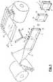
- Fig. 1schematically shows the main operations of a method for manufacturing flexible containers 1 of the type comprising a lower base 3 of essentially rectangular shape and four side faces 4, 5, 6a, 6b, using in the example only one main web 2 and an auxiliary web 21.
- Fig. 1it comprises the operation of supplying the web 2 from a web storage reel and of folding it upon itself around longitudinal fold lines forming a W shaped pleated area that determines an inverted "V" shaped bottom 3', a central fold 7 being distinguished, which remains arranged between two opposite walls 4', 5' of the web 2.
- this formation in Wis obtained by folding an initial single web 2
- the formation in Wcan be obtained from bonding together along longitudinal seams various starting webs. That is, in the context of the invention, the web, which is folded to obtain the form in W, may be formed by a single film or by several films bonded together.
- the methodcomprises the added steps of inserting folded sheets 66 into the web 2 between its opposite walls 4', 5' and obtaining the bond of these folded sheets 66 to the web 2 to determine pairs of dividing walls 6a', 6b' on the web 2, prior to performing transverse cuts on the web 2 to individualise a container 1, the cuts being distanced so that each container 1 includes, at least, two of said dividing walls 6a', 6b', which will form the two side walls 6a, 6b in each container 1.
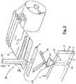
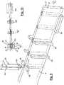
- Figs. 2 to 4shows a module 33, which provides the preparation of these folded sheets 66, their introduction into the web 2 and their preliminary bonding on the web 2.
- this module 33comprises means for folding and introducing means 28 that act in a coordinated manner to shape sheets 6 by folding them around preferential fold lines, and to move the already folded sheets 66 to arrange them inside the web 2.
- the folding means and introducing means 28comprise a pusher 22 movable in a direction essentially normal to the extension of the web 2 between two positions: a waiting position A (shown in Fig. 2 ) and an operative position B (shown in Figs. 4 and 10 ).
- the folding means and introducing means 28further comprise an introducing template 22', fixed in the example, generally funnel-shaped and adapted to be traversed by the pusher 22 in its run towards the web 2.
- the module 33also comprises means for supplying sheets 6 of adequate extension, in this case to form two sides of a finished container, manipulated to mark on them preferred fold lines, and to arrange them between the pusher 22 and the introducing template 22' when the pusher takes on the waiting position A.
- a series of ridges 31are machined or formed on the pusher 22 acting on the sheet 6 when the pusher is driven in the direction of the web 2 in such a way that they fold the sheet 6 along the cited preferential folding lines while they displace the sheet towards the web 2.
- These ridges 31act in combination with the passage section offered by the introducing template 22', whose profile determines the gauge of the pre-folded sheet 66 as it passes through said introducing template 22', all as shown in Fig. 2 .
- the module 33comprises means for drawing a continuous auxiliary web 21 from a corresponding storage reel; for transversely cutting the auxiliary web 21 to obtain the sheets 6; and to mark the sheets 6 in the preferred fold lines
- the inventionalso contemplates that the module 33 will be supplied sheets 6, dispensed from a sheet 6 storage reel. In this case, it is contemplated either that the sheets 6 stored are already marked or that the module 33 is provided with the necessary means to mark the sheets 6 before supplying them for introduction on the web 2.
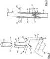
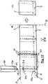
- the module 33is complemented by stop means 24, visible in Figs. 3 and 4 , for receiving the slidable support of the bottom 3' of the web 2 and ready to act as end of stroke for the folded sheet 66, with interposition of the bottom 3' of the web 2 during the insertion operation of the folded sheet 66 on the web 2.
- stop means 24contribute to the folded sheet 66 being perfectly positioned on the centre fold 7 of the web 2, which is of interest to perfect the manufacture of the packages 1.
- Figs. 3 and 4show how the module 33 is further provided with pre-welding means 23, prepared for provisionally bonding and in small areas the sheets 66 to each of the opposite walls 4', 5' of the web 2, once said sheets are perfectly positioned on the central fold 7 of the web 2.
- Fig. 4to facilitate the understanding of this operation, the pusher 22 has been shown out of the folded sheet 66 when in fact the folded sheet 66 envelops the outside of said pusher 22 during its movement in the direction of web 2, as is properly illustrated in Fig. 4 .
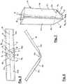
- Figs. 5 to 7show in detail a method of operation of particular interest for obtaining the folded sheet 66 from a sheet 6.
- Fig. 5it starts with an oblong sheet 6 of sufficient extension to form two side walls in the containers to be made.
- This sheet 6in its central area, has a series of fold lines 9 forming a rhombic figure engraved on the sheet 6, so that the two opposite vertices 9a, 9b end in respective edges 10, 11 of the sheet 6; and a straight fold line 12 with a central sector 12a extending between the other two vertices 9c, 9d of the rhombic figure 9 and two end sectors 12b, 12c, each extending from the central sector 12a to a corresponding end of the sheet 6.
- this central sector 12ais completely continuous, without interruption, contributes significantly to minimise undesirable defects in the making of the packages 1.
- Figs. 6 and 7are a sequence of the folding of the sheet 6. Specifically, the sheet 6 is folded in one direction around the end sectors 12c, 12b of the straight fold line 12 and in an opposite direction around the central sector 12a of said straight fold line allowing the sheet 6 to also fold around the sides 99a; 99b; 99c; 99d of the rhombic figure 9 to obtain the folded sheet 66 with the flattened form as illustrated in Fig. 7 . From this folded form the central sector 12a stands out, extending without interruption along the entire width of the folded sheet 66 and, consequently, allowing the correct positioning of the folded sheet 66 on the central fold 7 of the web 2.
- a sort of triangular peak 13is distinguished, folding down precisely around the central sector 12a of the straight fold line 12 and two side wings 14a, 14b which each determine a dividing wall 6a', 6b' (see Fig. 1 ) on the web 2.
- Fig. 8shows bonding portions 20a, 20b definable on the folded sheet 66 that will be attached to the opposite walls 4', 5' and to the bottom 3' of the web 2 when the folded sheet is arranged between the opposite walls 4', 5' thereof and the central sector 12a meets the central fold 7 of the web 2.
- each side wing 14a, 14bto each of the two opposite walls 4', 5' of the web 2, using the pre-welding means 23 prior to drawing the web 2 and proceeding to a downstream work station to bond the web 2 and the folded sheet 66 along the bonding portions 20a, 20b to form the double dividing wall 6a', 6b' on the web 2.
- the pre-welding means 23may consist of welding bars which provide heat to the material, of which the web 2 and the folded sheet 66 are made, for their bonding by heat welding. It is noted that the pusher 22 provides the necessary support so that the web 2 and the folded sheet 66 portion attached do not sink inward when the welding bars exert pressure from the exterior face of the opposite walls 4' and 5' of the web 2 during the operation of preliminary bonding between the web 2 and the folded sheet 66.
- the methodDownstream of this preliminary bonding operation, the method, which is illustrated by way of example, comprises the operations of performing transverse seals in the assembly formed by the web 2 and the sheets 66 in coincidence with the bonding portions 20a and 20b, for example by the set of welding bars 25; and making seams on the bottom 3' of the web 2 between the transverse seals and on each of the longitudinal folds of transition between said bottom 3' and each of the opposite walls 4' and 5', for example, by the set of welding bars 26.
- the welding bars 25 and 26may be of the type which provide heat for bonding by thermal welding the inner faces of the web 2, which are mutually attached, which occurs in the area of the transition folds between the bottom 3 and the opposite walls 4' and 5' of the web 2, in which there is no interference with the folded sheets 66, and also the contact areas between the folded sheet 66 and the web 2 in the bonding portions 20a and 20b.
- the stop means 24are heated, to assist that the thermal swing between the welding bars 25 and/or 26 and these internal points of the package be lower and require less time to perform a proper bond by thermal welding.
- the transverse cuts 16are performed (see Fig. 11 ) to individualise made containers.
- the cuts 16are made to coincide with each folded sheet 66 and particularly between each pair of dividing walls 6a', 6b' formed by the bond of each folded sheet 66 with the web 2.
- each container 1includes a folded sheet 66 in the middle, which can act as an intermediate partition, which provides the container the space to store, in this case, two separate products and/or products of a different nature.
- the methodcomprises first performing bonding seams on the bottom 3' of the web 2 between each two folded sheets 66 and each of the longitudinal folds of transition between said bottom 3' and each one of the opposite walls 4' and 5', by welding bars 26; subsequently making transverse seals on the assembly formed by the web 2 and the sheets 66 in coincidence with the bonding portions 20a and 20b, by the set of welding bars 25.
- packages 1Once individualised the packages 1, their filling and closing can be performed on the same production line using means identical to those used in a conventional module for filling and closing "doy-pack" type packages.
- the use of package transfer means of containers and a horizontal packaging machine as described in the patent document WO2014207278is contemplated.
- packages 1are made; and are filled and closed, for example, for delivery to a packing station.
- the methodcontemplates that the sheets 66 have, in each bonding portion 20a, 20b, or adjacent thereto, pairs of slits or perforations 27 which are overlaid when the folded sheet 66 is inserted into the web 2, so that the transverse seal with the welding bars 25 make contact through said slits or perforations and the subsequent bonding together of the opposite walls 4', 5' of the web 2, i.e., the side walls 4, 5 of the container 1 once the transverse cut 16 is performed.
- the bonding of the side walls 4 and 5gives the container 1 a flattened shape at its upper mouth, suitable to be held by its edges by means of respective clamps of the type that are used in its transportation and for the operations of opening, filling and closing.
- FIG. 16schematically shows a detail of the container obtainable according to the invention and illustrated in Figs. 14 and 15 from its upper opening, when said opening is forced into an open position.
- This container 1is provided with a fitting for reversible closure, for instance in the form of a zip type closure 35, shown schematically in Figs. 14 and 15 .
- the two halves of the side wings 14a and 14b of the corresponding side walls 6a, 6bare juxtaposed and folded down on one side, bonded in areas 36 to a side wall 4 or 5 of the container 1, in order to ensure the water/air tightness thereof when the side walls 4 and 5 are juxtaposed and bonded together and no product residue that fills the container 1 remains in the spout formed by the outer face of said side walls 6a and 6b, folded towards the inside of the container 1 at its upper end.
- the operations that are performed downstream of the preliminary bonding of the folded sheet 66 to the web 2are compatible, that is, they can be performed using the same means that machines that manufacture "doy-pack" type containers have for this purpose. These machines are also generally provided with means for supplying a starting web and for folding it upon itself in order to obtain a W shape.
Landscapes
- Engineering & Computer Science (AREA)
- Mechanical Engineering (AREA)
- Making Paper Articles (AREA)
- Auxiliary Devices For And Details Of Packaging Control (AREA)
Description
- The invention relates to a method for manufacturing flexible containers comprising a lower base of essentially rectangular configuration from which four side faces of the package, bonded together at their corners, rise. The invention also relates to a module for implementing the method and a machine incorporating said module.
- Conventionally, various containers sealed along a pair of sides have been proposed. This is the case for the "doy-pack" or "stand-up pouches" type containers.
- The patent document
WO 2014/04577 - Other type of containers are already known, which are made from flexible material adopting, when full, a form in which a flat, essentially rectangular base is distinguished, from which four side faces of the package, bonded at their corners, rise, two of which being juxtaposed on the top of the container closing its upper part. Such packages are sometimes identified in the trade under the name of "quad-seal" or "flat-bottom stand-up".
- Generally, to obtain said containers industrially, the use of various sheets of material forming the container, which will be suitably manipulated and bonded together for the formation of the container, is necessary. Such is the case, for example, of the ways of obtaining containers described in patent documents
US 2012231941 andWO 201540631 - An alternative to this procedure is described in
EP 1541332 , in which the same sheet forming a first larger side face of the container also forms the lower base thereof. However, this approach requires having to manipulate, in the middle of the container's formation, a critical area thereof. In particular, it is necessary to have to flatten the base of the container, once placed false sheets, which will form two smaller side faces of the container, in order to be able to bond to the base and to these false sheets another sheet that will form the second larger side wall of the container. - One of the objects of the invention is a method of production that allows obtaining containers with a smaller number of sheets.
- Moreover, the complexity of the machines used, to date, for the preparation of these packages is significantly higher than the machine which makes other also well-known containers, with only two side faces and consequently of various benefits, such as the "doy-pack" or "stand-up pouch" type containers, since the machines used are able to continually make containers from a single continuous film of flexible material that is drawn from a film storage reel, or of various films of flexible material drawn from respective film storage reels and which are bonded together along each longitudinal seam to form a single film, which, conveniently folded over itself and by bonding operations of certain parts of it, allows the formation of successive pockets open at their upper parts that are individualised by transverse cutting the film thereby obtaining open containers. Conventionally, these machines integrate modules for the filling and closure of the containers. Examples of machines for the manufacture of this type of "doy-pack" containers and various versions thereof are disclosed in the patents
US 5845463 ;US 4216639 andGB 2351035 - The increased complexity of machines capable of forming containers of "quad-seal" type makes the resulting container expensive, and that the use of said containers is only economically viable when the product the containers contain offers a generous profit margin to the packager.
- Therefore, largely due to the high cost and complexity of machines able to make "quad-seal" type containers, this part of the packaging process is often outsourced, so that there are first companies for the manufacture of containers and second companies, which, from pre-made containers, perform their filling and closing. This means that the packager has little control over the formation or manufacture of the containers and immediate changes in type of package are impossible, unless the packager has in stock pre-made containers of different types. As is known, stock incurs costs in storage and supply of the products in stock.
- It is also, therefore, an object of the present invention, a particularly suitable method and device to integrate the manufacturing phase of "quad-seal" type packaging with the subsequent packaging phase, for example in the same production line or in the same machine.
- It is also an object of the invention to provide a versatile method that allows making changes in the type of containers in a simple manner.
- Also another object of the invention is an alternative machine to known machines for making packages such as the "quad-seal" type, and of a module, which can manufacture "quad-seal" type containers in combination with technical solutions already known in the sector, in order to make possible adapting machines or known production processes for implementing the method according to the invention.
- The proposed method is suitable for the manufacture of flexible containers of the type comprising a lower base essentially in parallelogram configuration, such as, for example, square or rectangular, and four side faces, the method comprising the usual step in the manufacture of "doy-pack" type packages, comprising supplying a continuous web folded upon itself around longitudinal fold lines forming a W-shaped pleated area, which determines an inverted "V" shaped bottom, a central fold being distinguished, which is arranged between two opposite walls of the web; and the added steps of inserting folded sheets into the web between its opposite walls so that at least a bonding portion of each folded sheet is attached to the opposite walls and to the inverted "V" shaped bottom of the web, and bonding these folded sheets to the web at said bonding portion or portions to determine dividing walls on the web prior to performing transverse cuts on the web to individualise a container, the cuts being distanced so that each container includes, at least, two of said dividing walls that will form respective side walls on each container.
- Advantageously, the method according to the invention shares operations that are already common for the manufacture of another type of containers in the industry, even if dealing with different containers as are the "doy-pack" type containers.
- This allows that a single machine may be prepared to manufacture containers of two different types, that is the "doy-pack" type container or the "quad-seal" type container. Logically, a machine with this capability offers very interesting advantages to packagers, who will be able to obtain line production of "quad-seal" type containers, whereas now they have to work with pre-made packaging.
- In a variant of the method, the extension of the folded sheets is suitable for making each one two side faces of two containers to be manufactured consecutively, each folded sheet comprising two bonding portions, whose bonds with the opposite walls and with the bottom determine a double dividing wall on the web, and the method comprises performing transverse cuts on the web between the bonding portions of the same folded sheet, so that on each side of the transverse cuts a dividing wall will form one side wall of two consecutive containers.
- According to one embodiment, the method comprises the operations of providing sheets of suitable extension to make each one two side faces of two containers to be manufactured consecutively, each sheet having a central area of a series of fold lines as a rhombic figure, engraved on the sheet in such a way that two opposite vertices end up on respective edges of the sheet; and of a straight fold line with a central sector extending between the other two vertices of the rhombic figure and two end sectors extending each one from the central sector to a corresponding end of the sheet; folding the sheet in a direction around the end sectors of the straight fold line and folding the sheet in an opposite direction around the central section of said straight fold line allowing that the sheet also folds itself around the sides of the rhombic figure to obtain a folded sheet, which determines a flattened formation, wherein a sort of triangular peak, able to fold down or fold out around the central sector of the straight fold line, is distinguished, and two side wings, which each determine a dividing wall on the web; arranging the thus folded sheet between the opposite walls of the web in such a way that the central sector of the straight fold line meets the central fold of the inverted "V" shaped bottom formed on the web, the edges of the folded sheet and its straight imaginary extensions through the interior part of the peak determining respective bonding portions of the folded sheet, which remain attached to the opposite walls and the bottom of the web; and bonding the web and the folded sheet on said bonding portions to form the double dividing wall on the web.
- The invention provides that, prior to bonding the web and the folded sheet on said bonding portions to form the double dividing wall on the web, a preliminary operation of bonding the sheet to the web is performed, consisting of bonding small areas of each side wing to each one of the two opposite walls of the web.
- As for the sheets, these can be cut from a continuous auxiliary web drawn from another web storage reel, and the marking of fold lines according to the rhombic figure and to the straight fold line can be made on them, prior to or after being cut from the auxiliary web.
- In a variant, the method comprises performing longitudinal bonding seams on the web, coinciding with the folding lines, which limit the "V" shaped bottom with each of the opposite walls of the web once the folded sheets are inserted into the web.
- In a variant, the folded sheets or the sheets from which the folded form is obtained, have at each bonding portion, or adjacent thereto, pairs of slits or perforations, which overlie when the folded sheet is inserted into the web, the method comprising the operation of bonding together the opposite walls of the web or the side walls of a container through said slits or perforations.
- Note that the operations, which are performed after introducing the folded sheets between the opposite walls of the web in the manufacture of "quad-seal" type packages may be consistent with those performed in the manufacture of "doy-pack" type packages. This allows, as discussed below, that, at least, the operations of filling and closing the packages can be performed in a package filling and closing module located downstream from the transverse cuts operation of the web and that these means do not have to be altered depending on whether the manufactured containers are of one type or another. Moreover, even the means used to perform transverse seals on the web and to form seams on the base of the containers may be consistent to both packages. Therefore, there is the possibility of making the "quad-seal" type containers and filling and closing them in the same machine, which is also able to make "doy-pack" type containers, using the same means for sealing, cutting, filling and closing of the containers.
- That is why, according to another aspect of the invention, a method is disclosed for manufacturing flexible containers of the type comprising a lower base and at least two opposite side faces, comprising the operation of supplying a continuous web folded upon itself around longitudinal fold lines forming a W-shaped pleated area, which determines an inverted "V" shaped bottom, a central fold being distinguished, which is arranged between two opposite walls of the web, intended to form respective first and second opposite side faces of a container, the method being characterised in that it comprises selecting the type of container to be manufactured from at least two types
- a first type, in which the side faces of the container are bonded together by determining two side seams in the finished container, for which the method comprises the step of performing transverse seals on the web to bond the opposite walls of the web together prior to cutting the web transversely to individualise a container; or
- a second type, in which, between the side faces of the container, on each side of the container, a third and a fourth side face are interposed, providing the container with the ability to take, on standing, an essentially quadrangular or square shape, for which the method comprises the step of inserting and bonding folded sheets on the web between its opposite walls to determine dividing walls on the web prior to performing transverse cuts on the web to individualise a container, the cuts being distanced so that each container includes at least two of such dividing walls that will form respective side walls on each container.
- According to another aspect of the invention, a module for implementation of the method is presented, said module comprising means prepared for supplying previously manipulated sheets for their marking with preferential folding lines; folding means and introducing means, which act in a coordinated manner to shape the sheet by folding it around the preferential folding lines and to accompany the folded sheet to arrange it within the web and so that, at least, one bonding portion on the folded sheet is attached to the opposite faces and the inverted "V" shaped bottom of the web; and means of obtaining the bonding of these sheets to the web on said bonding portions to determine dividing walls on the web.
- The folding means and introducing means comprise a pusher, movable toward the web in a direction essentially normal to the extension thereof; and an introducing template, generally funnel-shaped and intended to be traversed by the assembly formed by the pusher and the folded sheet that accompanies said pusher in its trajectory towards the web.
- In a preferred embodiment, the folding means and introducing means comprise a series of ridges formed on the pusher acting on the sheet during its pushing in combination with the passage section offered by the introducing template, whose profile determines the gauge of the folded sheet on its passage through the introducing template.
- Preferably, the module comprises stop means for receiving the slidable support of the bottom of the web and prepared to act as end of stroke of the folded sheet with interposition of the bottom of said web.
- It is contemplated that the stop means are heated.
- In a variant, the module comprises means for pre-welding, prepared for provisionally bonding and in small areas, the sheets to each of the opposite walls of the web.
- A machine for manufacturing flexible containers of the type comprising a lower base in essentially parallelogram configuration and four side faces, which may comprise means for supplying a continuous web folded upon itself around longitudinal fold lines forming a W-shaped pleated area, which determines an inverted "V" shaped bottom, a central fold being distinguished, which is arranged between two opposite walls of the web; and a module according to the invention.
- Among the obtainable containers with the method, according to the invention, is of interest a flexible container comprising a lower base in essentially parallelogram configuration, from which, four side faces rise, the lower base and two of its noncontiguous side faces being integrally formed by the same sheet; and the two remaining side faces by respective auxiliary sheets; wherein said remaining side faces are in a top part of the container folded towards the interior thereof, the container being able to take on in said top part a flat shape by juxtaposing the side faces; and, in which to prevent the unfolding of said side faces the container is further provided with features of the claim 15.
Fig. 1 is a schematic view of the method according to one variant of the invention;Fig. 2 is a view of a module for introducing a folded sheet between the opposite walls of the web, from which two side faces and the base of a container will be formed;FIG. 3 is a schematic view of the operation of introducing the folded sheet between the opposite walls of the web;Fig. 4 is a sectional view along a normal cutting plane of the web showing the moment that the folded sheet is arranged between the opposite walls of the web so that the folded sheet meets the centre fold of the inverted "V" shaped bottom;Figs. 5, 6 and 7 are a sequence of obtaining the folded sheet from a sheet marked with the preferred fold lines;Fig. 8a shows the folded sheet, with two bonding portions for bonding the opposite walls of the web to form a double dividing wall having been indicated;Fig. 8b shows the folded sheet ofFig. 8a , as a bottom view, with its peak portion completely open to illustrate the bonding portions with the bottom of the web in this part of the folded sheet;Figs. 9 and 10 show respective schematic views in perspective and plan view, respectively, of the operations performed after the folded sheets are inserted between the walls of the web;Fig. 11 is another schematic view and according to an alternative to the method ofFig. 10 of the operations performed after the folded sheets are inserted between the walls of the web;Figs. 12 and 13 show an empty, finished container and when it takes on a filled form, respectively, obtainable with the method of the invention;Figs. 14 and 15 show another empty, finished container and when it takes on a filled form, respectively, obtainable with the method of the invention;Fig. 16a shows schematically and in section the package ofFigs. 14 and 15 ; andFig. 16b shows in greater detail but schematically the same container in an open form, along the cutting plane AA ofFig. 16a .Fig. 1 schematically shows the main operations of a method for manufacturingflexible containers 1 of the type comprising alower base 3 of essentially rectangular shape and four side faces 4, 5, 6a, 6b, using in the example only onemain web 2 and anauxiliary web 21.- In the method of
Fig. 1 , it comprises the operation of supplying theweb 2 from a web storage reel and of folding it upon itself around longitudinal fold lines forming a W shaped pleated area that determines an inverted "V" shaped bottom 3', acentral fold 7 being distinguished, which remains arranged between two opposite walls 4', 5' of theweb 2. - While in this example this formation in W is obtained by folding an initial
single web 2, it is understood that the formation in W can be obtained from bonding together along longitudinal seams various starting webs. That is, in the context of the invention, the web, which is folded to obtain the form in W, may be formed by a single film or by several films bonded together. - As illustrated in
Fig. 1 , having been obtained the formation in W, the method comprises the added steps of inserting foldedsheets 66 into theweb 2 between its opposite walls 4', 5' and obtaining the bond of these foldedsheets 66 to theweb 2 to determine pairs of dividing walls 6a', 6b' on theweb 2, prior to performing transverse cuts on theweb 2 to individualise acontainer 1, the cuts being distanced so that eachcontainer 1 includes, at least, two of said dividing walls 6a', 6b', which will form the twoside walls 6a, 6b in eachcontainer 1. Figs. 2 to 4 shows amodule 33, which provides the preparation of these foldedsheets 66, their introduction into theweb 2 and their preliminary bonding on theweb 2.- Specifically, this
module 33 comprises means for folding and introducingmeans 28 that act in a coordinated manner to shapesheets 6 by folding them around preferential fold lines, and to move the already foldedsheets 66 to arrange them inside theweb 2. - In the example of
Fig. 2 , the folding means and introducingmeans 28 comprise apusher 22 movable in a direction essentially normal to the extension of theweb 2 between two positions: a waiting position A (shown inFig. 2 ) and an operative position B (shown inFigs. 4 and10 ). - The folding means and introducing
means 28 further comprise an introducing template 22', fixed in the example, generally funnel-shaped and adapted to be traversed by thepusher 22 in its run towards theweb 2. - The
module 33 also comprises means for supplyingsheets 6 of adequate extension, in this case to form two sides of a finished container, manipulated to mark on them preferred fold lines, and to arrange them between thepusher 22 and the introducing template 22' when the pusher takes on the waiting position A. - A series of
ridges 31 are machined or formed on thepusher 22 acting on thesheet 6 when the pusher is driven in the direction of theweb 2 in such a way that they fold thesheet 6 along the cited preferential folding lines while they displace the sheet towards theweb 2. Theseridges 31 act in combination with the passage section offered by the introducing template 22', whose profile determines the gauge of thepre-folded sheet 66 as it passes through said introducing template 22', all as shown inFig. 2 . - Although in the example, the
module 33 comprises means for drawing a continuousauxiliary web 21 from a corresponding storage reel; for transversely cutting theauxiliary web 21 to obtain thesheets 6; and to mark thesheets 6 in the preferred fold lines, the invention also contemplates that themodule 33 will be suppliedsheets 6, dispensed from asheet 6 storage reel. In this case, it is contemplated either that thesheets 6 stored are already marked or that themodule 33 is provided with the necessary means to mark thesheets 6 before supplying them for introduction on theweb 2. - In either case, the
module 33 is complemented by stop means 24, visible inFigs. 3 and 4 , for receiving the slidable support of the bottom 3' of theweb 2 and ready to act as end of stroke for the foldedsheet 66, with interposition of the bottom 3' of theweb 2 during the insertion operation of the foldedsheet 66 on theweb 2. - These stop means 24 contribute to the folded
sheet 66 being perfectly positioned on thecentre fold 7 of theweb 2, which is of interest to perfect the manufacture of thepackages 1. - This operation is illustrated in greater detail in
Figs. 3 and 4 , which show how themodule 33 is further provided with pre-welding means 23, prepared for provisionally bonding and in small areas thesheets 66 to each of the opposite walls 4', 5' of theweb 2, once said sheets are perfectly positioned on thecentral fold 7 of theweb 2. InFig. 4 , to facilitate the understanding of this operation, thepusher 22 has been shown out of the foldedsheet 66 when in fact the foldedsheet 66 envelops the outside of saidpusher 22 during its movement in the direction ofweb 2, as is properly illustrated inFig. 4 . Figs. 5 to 7 show in detail a method of operation of particular interest for obtaining the foldedsheet 66 from asheet 6.- According to this method of operation, as shown in
Fig. 5 , it starts with anoblong sheet 6 of sufficient extension to form two side walls in the containers to be made. Thissheet 6, in its central area, has a series offold lines 9 forming a rhombic figure engraved on thesheet 6, so that the two opposite vertices 9a, 9b end inrespective edges sheet 6; and astraight fold line 12 with acentral sector 12a extending between the other two vertices 9c, 9d of the rhombicfigure 9 and twoend sectors central sector 12a to a corresponding end of thesheet 6. As explained below, the fact that thiscentral sector 12a is completely continuous, without interruption, contributes significantly to minimise undesirable defects in the making of thepackages 1. Figs. 6 and 7 are a sequence of the folding of thesheet 6. Specifically, thesheet 6 is folded in one direction around theend sectors straight fold line 12 and in an opposite direction around thecentral sector 12a of said straight fold line allowing thesheet 6 to also fold around thesides 99a; 99b; 99c; 99d of the rhombicfigure 9 to obtain the foldedsheet 66 with the flattened form as illustrated inFig. 7 . From this folded form thecentral sector 12a stands out, extending without interruption along the entire width of the foldedsheet 66 and, consequently, allowing the correct positioning of the foldedsheet 66 on thecentral fold 7 of theweb 2.- In the flattened formation of said
Fig. 7 a sort oftriangular peak 13 is distinguished, folding down precisely around thecentral sector 12a of thestraight fold line 12 and twoside wings 14a, 14b which each determine a dividing wall 6a', 6b' (seeFig. 1 ) on theweb 2. - It is of interest to note that the inner surface of the
peak 13, shown unfolded inFig. 8a , intended to be juxtaposed to thebottom 3 of theweb 2, is in fact a surface without interruption, determined by the rhombicfigure 9 on the startingsheet 6. - These
side wings 14a, 14b remain perfectly parallel and vertical, that is, normal to thecentral fold 7 and consequently the future base of the made container, through seamless support offered by thecentral sector 12a, favouring the correct making of said container. Fig. 8 showsbonding portions sheet 66 that will be attached to the opposite walls 4', 5' and to the bottom 3' of theweb 2 when the folded sheet is arranged between the opposite walls 4', 5' thereof and thecentral sector 12a meets thecentral fold 7 of theweb 2. With the foldedsheet 66 conveniently placed in this position, without removing thepusher 22, as illustrated inFigs. 4 and10 , a preliminary bonding operation of thesheet 66 to theweb 2 consisting of bondingsmall areas 34 is performed, (seeFigs. 9 and11 ) of eachside wing 14a, 14b to each of the two opposite walls 4', 5' of theweb 2, using the pre-welding means 23 prior to drawing theweb 2 and proceeding to a downstream work station to bond theweb 2 and the foldedsheet 66 along thebonding portions web 2.- In a way known per se, the pre-welding means 23 may consist of welding bars which provide heat to the material, of which the
web 2 and the foldedsheet 66 are made, for their bonding by heat welding. It is noted that thepusher 22 provides the necessary support so that theweb 2 and the foldedsheet 66 portion attached do not sink inward when the welding bars exert pressure from the exterior face of the opposite walls 4' and 5' of theweb 2 during the operation of preliminary bonding between theweb 2 and the foldedsheet 66. - Downstream of this preliminary bonding operation, the method, which is illustrated by way of example, comprises the operations of performing transverse seals in the assembly formed by the
web 2 and thesheets 66 in coincidence with thebonding portions web 2 between the transverse seals and on each of the longitudinal folds of transition between said bottom 3' and each of the opposite walls 4' and 5', for example, by the set of welding bars 26. The welding bars 25 and 26 may be of the type which provide heat for bonding by thermal welding the inner faces of theweb 2, which are mutually attached, which occurs in the area of the transition folds between the bottom 3 and the opposite walls 4' and 5' of theweb 2, in which there is no interference with the foldedsheets 66, and also the contact areas between the foldedsheet 66 and theweb 2 in thebonding portions - In order that the temperature be suitable in the areas more separated from the welding bars 25 and 26, that is, in the innermost points of the package formed by the
web 2 and the foldedsheet 66, for example in the area of thebonding portions web 2 in the vicinity of thecentral sector 12a, it is contemplated that the stop means 24 are heated, to assist that the thermal swing between the welding bars 25 and/or 26 and these internal points of the package be lower and require less time to perform a proper bond by thermal welding. - Subsequently, the
transverse cuts 16 are performed (seeFig. 11 ) to individualise made containers. In the example, thecuts 16 are made to coincide with each foldedsheet 66 and particularly between each pair of dividing walls 6a', 6b' formed by the bond of each foldedsheet 66 with theweb 2. - In other provided variants, it is possible to distance the
transverse cuts 16 so that the cut is performed every two or more foldedsheets 66, so that eachcontainer 1 includes a foldedsheet 66 in the middle, which can act as an intermediate partition, which provides the container the space to store, in this case, two separate products and/or products of a different nature. - In a variant of the method illustrated in
Fig. 11 , downstream of the preliminary bonding operation, the method comprises first performing bonding seams on the bottom 3' of theweb 2 between each two foldedsheets 66 and each of the longitudinal folds of transition between said bottom 3' and each one of the opposite walls 4' and 5', by weldingbars 26; subsequently making transverse seals on the assembly formed by theweb 2 and thesheets 66 in coincidence with thebonding portions - The effects produced on a
finished container 1 by the welding bars 25 and 26 are schematically represented in thepackage 1 ofFigs. 13 and15 , with the references 25' and 26', respectively. - Once individualised the
packages 1, their filling and closing can be performed on the same production line using means identical to those used in a conventional module for filling and closing "doy-pack" type packages. For example, the use of package transfer means of containers and a horizontal packaging machine as described in the patent documentWO2014207278 is contemplated. Thus, in one single production line, packages 1 are made; and are filled and closed, for example, for delivery to a packing station. - In the example of
Figs. 13 and14 , for directly bonding theside walls sheets 66 have, in eachbonding portion perforations 27 which are overlaid when the foldedsheet 66 is inserted into theweb 2, so that the transverse seal with the welding bars 25 make contact through said slits or perforations and the subsequent bonding together of the opposite walls 4', 5' of theweb 2, i.e., theside walls container 1 once thetransverse cut 16 is performed. The bonding of theside walls Fig. 16 schematically shows a detail of the container obtainable according to the invention and illustrated inFigs. 14 and 15 from its upper opening, when said opening is forced into an open position. Thiscontainer 1 is provided with a fitting for reversible closure, for instance in the form of azip type closure 35, shown schematically inFigs. 14 and 15 .- In this case, it may be of interest that the two halves of the
side wings 14a and 14b of thecorresponding side walls 6a, 6b are juxtaposed and folded down on one side, bonded inareas 36 to aside wall container 1, in order to ensure the water/air tightness thereof when theside walls container 1 remains in the spout formed by the outer face of saidside walls 6a and 6b, folded towards the inside of thecontainer 1 at its upper end. - Advantageously, the operations that are performed downstream of the preliminary bonding of the folded
sheet 66 to theweb 2 are compatible, that is, they can be performed using the same means that machines that manufacture "doy-pack" type containers have for this purpose. These machines are also generally provided with means for supplying a starting web and for folding it upon itself in order to obtain a W shape. Consequently, by equipping a machine of this type with amodule 33 it is possible to manufacture "doy-pack" type containers or "quad-seal" type containers simply enabling or disabling themodule 33, i.e., choosing if it is desired to introduce or not, between the opposite walls 4', 5' of theweb 2, the foldedsheets 66, whose bonding with the web form first dividing walls 6a', 6b' on thecontinuous web 2, which, subsequently, will become side faces 6a, 6b in made containers when proceeding to transversely cut theweb 2 in coincidence with the foldedsheets 66 as explained above.
Claims (15)
- A method for manufacturing flexible containers (1) of the type comprising a lower base (3) of essentially parallelogram configuration and four side faces (4, 5, 6a, 6b), the method comprising the operations of- supplying a continuous web (2) folded upon itself around longitudinal fold lines forming a W-shaped pleated area determining an inverted "V" shaped bottom (3'), a central fold (7) being distinguished, which remains arranged between two opposite walls (4', 5') of the web (2)- inserting folded sheets (66) into the web (2) between its opposite walls (4 ', 5') so that, at least, one bonding portion (20a, 20b) in each folded sheet (66) is attached to the opposite walls (4', 5') and to the inverted "V" shaped bottom (3') of the web (2), and- bonding said folded sheets (66) to the web (2) in said bonding portion or portions (20a, 20b) to determine dividing walls (6a', 6b') on the web (2) prior to performing transverse cuts (16) on the web (2) to individualise a container (1), the cuts (16) being distanced so that each container (1) includes, at least, two of said dividing walls (6a', 6b'), which will form the two respective side walls (6a, 6b) in each container (1).
- The method, according to claim 1,characterised in that the extension of the folded sheets (66) is suitable for making each one two side faces (6a, 6b) of two containers to be manufactured consecutively, each folded sheet (66) comprising two bonding portions (20a and 20b) whose bonds with the opposite walls (4', 5') and with the bottom (3') determine a double dividing wall (6a' and 6b') on the web (2), andin that the method comprises performing transverse cuts (16) on the web (2) between the bonding portions (20a and 20b) of the same folded sheet (66), so that on each side of the transverse cut (16) a dividing wall (6a', 6b') will form one side wall (6a, 6b) of two consecutive containers.
- The method, according to the preceding claim,characterised in that it comprises the operations of- supplying sheets (6) of suitable extension for making each one two side faces (6a, 6b) of two containers to be manufactured consecutively, each sheet (6) having, in a central area, a series of fold lines forming a rhombic figure (9), engraved on the sheet (6), so that the two opposite vertices (9a, 9b) end in respective edges (10, 11) of the sheet (6); and a straight fold line (12) with a central sector (12a) extending between the other two vertices (9c, 9d) of the rhombic figure (9) and two end sectors (12b, 12c) each extending from the central sector (12a) to a corresponding end of the sheet (6).- folding the sheet (6) in a direction around the end sectors (12b, 12 c) of the straight fold line (12) and folding, in an opposite direction, the sheet (6) around the central sector (12a) of said straight fold line, allowing that the sheet is also folded around the sides (99a; 99b; 99c; 99d) of the rhombic figure (9) to obtain a folded sheet (66), determining a flattened formation, in which a sort of triangular peak (13) is distinguished able to fold down around the central sector (12a) of the straight fold line (12), and two side wings (14a, 14b), which each will determine a dividing wall (6a', 6b') on the web (2);- arranging the thus folded sheet (66) between the opposite walls (4', 5') of the web (2), so that the central sector (12a) of the straight fold line (12) meets the centre fold (7) of the inverted "V" shaped bottom (3') on the web (2), the edges (10, 11) of the folded sheet (66) and its straight imaginary extensions through the inside part of the spout (13) determining respective bonding portions (20a, 20b) of the folded sheet (66), which remain attached to the opposite walls (4', 5') and the bottom (3') of the web (2); and- bonding the web (2) and the folded sheet (66) in said bonding portions (20a, 20b) to form the double dividing wall (6a', 6b') on the web (2).
- The method, according to the preceding claim,characterised in that, prior to bonding the web (2) and the folded sheet (66) on said bonding portions (20a, 20b) to form the double dividing wall (6a', 6b') on the web (2), a preliminary operation of bonding the sheet (66) to the web (2) is performed, consisting of bonding small areas (34) of each side wing (14a, 14b) to each one of the two opposite walls (4', 5') of the web (2).
- The method, according to any of claims 3 or 4,characterised in that the sheets (6) are cut from a continuous auxiliary web (21) drawn from another storage web reel and, andin that fold lines according to the rhombic figure (9) and to the straight fold line (12) are marked on them prior to or after being cut from the auxiliary web (21).
- The method according to any one of the preceding claims, comprising performing longitudinal bonding seams on the web (2) coinciding with the folding lines, which limit the "V" shaped bottom (3) with each of the opposite walls (4', 5') of the web (2) once the folded sheets (66) are inserted into the web (2).
- The method according to any one of the preceding claims, wherein the folded sheets (66) have, at each bonding portion (20a, 20b) or adjacent thereto, pairs of slits or perforations (27), which overlie when the folded sheet (66) is introduced into the web (2), the method comprising the operation of bonding together the opposite walls (4', 5') of the web (2) or the side walls (4', 5') of a container (1) through said slits or perforations (27).
- A method for the manufacture of flexible containers (1) of the type comprising a lower base (3) and, at least, two opposite side faces (4, 5), comprising the operations of- supplying a continuous web (2) folded upon itself around longitudinal fold lines forming a W-shaped pleated area determining an inverted "V" shaped bottom (3'), a central fold (7) being distinguished, which remains arranged between two opposite walls (4', 5') of the web (2), intended to form respectively first and second opposite side faces (4, 5) of a container, the method beingcharacterised in that it comprises choosing the type of container to be manufactured from at least two types- a first type in which the side faces (4, 5) of the container are bonded together by determining two side seams in the finished container, for which the method comprises the step of performing transverse seals on the web to bond the opposite walls (4' and 5') together of the web prior to cutting the web (2) transversely to individualise a container; or- a second type in which, between the side faces (4, 5) of the container, a third (6a) and a fourth (6b) side face are interposed on each side of the container, providing the container with the ability to take, on standing, an essentially quadrangular or square shape, for which the method comprises the step of inserting folded sheets (66) on the web (2) between its opposite walls (4', 5') so that at least one bonding portion (20a, 20b) on each folded sheet (66) is attached to the opposite walls (4', 5') and the inverted "V" shaped bottom (3') of the web (2); and bonding these folded sheets (66) to the web (2) in said bonding portion or portions (20a, 20b) to determine dividing walls (6a', 6b') on the web (2) prior to transverse cutting (16) on the web (2) to individualise a container (1), the cuts (16) being distanced so that each container (1) includes, at least, two of said dividing walls (6a', 6b'), that will form respective side walls (6a, 6b) in each container (1).
- A module (33) for the manufacture of flexible containers (1), adapted to form dividing walls (6a', 6b') on a continuous web (2) folded upon itself around longitudinal fold lines forming a W-shaped pleated area that determines an inverted "V" shaped bottom (3'), a central fold (7) being distinguished, which remains arranged between two opposite walls (4', 5') of the web (2), the module comprising- means prepared for supplying previously manipulated sheets (6) to mark preferred fold lines on them;- folding means and introducing means (28) acting in a coordinated manner to shape the sheet (6) by folding it around the preferential fold lines and accompanying the folded sheet (66) until arranging it within the web (2) and so that, at least, one bonding portion (20a, 20b) on the folded sheet (66) is attached to the opposite faces (4', 5') and to the inverted "V" shaped bottom (3') of the web (2); and- means for bonding these sheets (66) to the web (2) on said bonding portions (20) for determining dividing walls (6a ', 6b') on the web (2), wherein the folding means and introducing means (29) comprise a pusher (22), movable toward the web (2) in a direction essentially normal to the extension thereof; and an introducing template (22'), generally funnel-shaped and intended to be traversed by the assembly formed by the pusher and the folded sheet (66) that accompanies said pusher (22) in its trajectory towards the web (2).
- The module (33), according to the preceding claim,characterised in that the folding means and introducing means (28) comprise a series of ridges (31) formed on the pusher (22) acting on the sheet (6) during its pushing in combination with the passage section offered by the introducing template (22'), whose profile determines the gauge of the folded sheet on its passage through the introducing template (22').
- The module (33), according to any one of Claims 9 to 10,characterised in that it comprises stop means (24) for receiving the slidable support of the bottom(3') of the web (2) and prepared to act as end of stroke of the folded sheet (66) with interposition of the bottom (3') of said web (2).
- The module (33), according to the preceding claim,characterised in that the stop means (24) are heated.
- The module (33), according to any one of Claims 9 to 12,characterised in that it comprises means for pre-welding (23), prepared for provisionally bonding in small areas the sheets (66) to each of the opposite walls (4', 5') of the web (2).
- A machine for the manufacture of flexible containers (1) of the type comprising a lower base (3) of essentially parallelogram configuration and four side faces (4, 5, 6a, 6b), the machine comprising- means for supplying a continuous web (2) folded upon itself around longitudinal fold lines forming a W-shaped pleated area determining an inverted "V" shaped bottom (3'), a central fold (7) being distinguished, which remains arranged between two opposite walls (4', 5') of the web (2); and- a module according to any one of Claims 9 to 13.
- A flexible container (1) comprising a lower base (3) of essentially parallelogram configuration, from which, four sides faces rise (4, 5, 6a, 6b), the lower base (3) and two of its noncontiguous side faces (4, 5) being integrally formed by the same sheet; and the two remaining side faces (6a, 6b) by respective auxiliary sheets; wherein said remaining side faces are in a top part of the container (1) folded towards the interior thereof, the container being able to take on, in said top part, a flat shape by juxtaposing the side faces (4, 5); and in which, to prevent the unfolding of said remaining side faces in the top part of the container- the side faces (4, 5), in the area near the upper mouth of the container, are directly bonded to each other through pairs of slits or perforations (27)- made in each of the remaining side faces (6a, 6b) and that- are overlaid when the said remaining side faces are folded towards the interior of the container; and/or- each of the remaining side faces (6a, 6b) are folded down on one of the side faces (4 or 5) and bonded to the said one of the side faces.
Priority Applications (1)
| Application Number | Priority Date | Filing Date | Title |
|---|---|---|---|
| PL16759813TPL3326797T3 (en) | 2015-07-24 | 2016-07-15 | Flexible containers comprising a lower base of essentially rectangular configuration, method, module and machine for their manufacture |
Applications Claiming Priority (2)
| Application Number | Priority Date | Filing Date | Title |
|---|---|---|---|
| ES201531100AES2600166B1 (en) | 2015-07-24 | 2015-07-24 | A process for the manufacture of flexible containers comprising a bottom base of essentially rectangular configuration |
| PCT/ES2016/070536WO2017017298A1 (en) | 2015-07-24 | 2016-07-15 | Flexible containers comprising a lower base of essentially rectangular configuration, method, module and machine for their manufacture |
Publications (2)
| Publication Number | Publication Date |
|---|---|
| EP3326797A1 EP3326797A1 (en) | 2018-05-30 |
| EP3326797B1true EP3326797B1 (en) | 2021-05-26 |
Family
ID=56852287
Family Applications (1)
| Application Number | Title | Priority Date | Filing Date |
|---|---|---|---|
| EP16759813.5AActiveEP3326797B1 (en) | 2015-07-24 | 2016-07-15 | Flexible containers comprising a lower base of essentially rectangular configuration, method, module and machine for their manufacture |
Country Status (5)
| Country | Link |
|---|---|
| US (1) | US20180370173A1 (en) |
| EP (1) | EP3326797B1 (en) |
| ES (2) | ES2600166B1 (en) |
| PL (1) | PL3326797T3 (en) |
| WO (1) | WO2017017298A1 (en) |
Families Citing this family (6)
| Publication number | Priority date | Publication date | Assignee | Title |
|---|---|---|---|---|
| FR3053586A1 (en)* | 2016-07-08 | 2018-01-12 | Sartorius Stedim Fmt Sas | 3D POCKET FOR EMPLOYING BIOPHARMACEUTICAL FLUIDS, AND METHOD FOR MAKING SUCH A POCKET |
| IT201800005107A1 (en)* | 2018-05-07 | 2019-11-07 | PRODUCTION OF SEALABLE PACKAGES WITH SIDE BELLOWS | |
| IT201800005111A1 (en)* | 2018-05-07 | 2019-11-07 | PRODUCTION OF SEALABLE PACKAGES WITH SIDE BELLOWS | |
| CN109334105B (en)* | 2018-08-30 | 2024-04-12 | 浙江正威机械有限公司 | Automatic plastic three-dimensional bag making system with patch entrained at square bottom |
| CN109955532B (en)* | 2019-04-18 | 2024-06-14 | 上海洲泰轻工机械制造有限公司 | Processing equipment and processing method for upper and lower film integrated packaging bags |
| CN115195200A (en)* | 2022-07-22 | 2022-10-18 | 中山市新宏业自动化工业有限公司 | Packaging bag manufacturing method and organ material conveying device |
Citations (1)
| Publication number | Priority date | Publication date | Assignee | Title |
|---|---|---|---|---|
| EP1541332A1 (en)* | 2002-07-24 | 2005-06-15 | Totani Corporation | Bag making machine |
Family Cites Families (16)
| Publication number | Priority date | Publication date | Assignee | Title |
|---|---|---|---|---|
| FR2417445A2 (en)* | 1978-02-15 | 1979-09-14 | Vittel Eaux Min | CONTAINER IN SYNTHETIC, THIN AND FLEXIBLE MATERIAL |
| NO152870C (en)* | 1983-09-01 | 1985-12-04 | Norsk Hydro As | LARGE BAG WITH TRACT-SHAPED BOTTOM. |
| US5236531A (en)* | 1988-05-17 | 1993-08-17 | Altech Co., Ltd. | Manufacturing method of square bottom containers |
| GB2317159B (en)* | 1996-02-13 | 1999-10-13 | Hosokawa Yoko Kk | Bag and method for manufacturing same |
| DE19910264A1 (en)* | 1999-03-08 | 2000-09-14 | Reinhold Klaus Masch & Geraete | Method for producing a packaging material from plastic film or the like weldable material |
| US6227439B1 (en)* | 1999-06-01 | 2001-05-08 | Multi-Pak As | Flexible bag in the box container for liquids |
| DK1106339T3 (en)* | 1999-12-02 | 2007-01-29 | Totani Corp | Device for making plastic bags |
| JP3672469B2 (en)* | 1999-12-03 | 2005-07-20 | 株式会社細川洋行 | Gusset bag manufacturing method and apparatus |
| ITPD20020217A1 (en)* | 2002-08-07 | 2004-02-08 | Zetatre Shoppers Srl | PARTIALLY TRANSPARENT BAG STRUCTURE AND EQUIPMENT FOR ITS REALIZATION. |
| EP3292996A1 (en)* | 2008-04-24 | 2018-03-14 | Totani Corporation | Bag making machine |
| JP4499832B1 (en)* | 2010-02-05 | 2010-07-07 | トタニ技研工業株式会社 | Bag making machine |
| WO2012044452A1 (en)* | 2010-09-15 | 2012-04-05 | Vir Narula | Reinforced bag |
| US8579780B2 (en)* | 2011-03-11 | 2013-11-12 | Totani Corporation | Plastic bag making apparatus |
| CN104603016B (en)* | 2012-09-19 | 2016-10-12 | 有限会社早川制袋 | Closing shaped bag with adhesive tape |
| PL3046754T3 (en)* | 2013-09-18 | 2019-10-31 | Mamata Machinery Pvt Ltd | Machine and method for manufacturing plastic pouches |
| US9962898B1 (en)* | 2014-08-25 | 2018-05-08 | James Russell | Method of manufacturing a bottom gusseted pouch |
- 2015
- 2015-07-24ESES201531100Apatent/ES2600166B1/enactiveActive
- 2016
- 2016-07-15ESES16759813Tpatent/ES2879816T3/enactiveActive
- 2016-07-15PLPL16759813Tpatent/PL3326797T3/enunknown
- 2016-07-15WOPCT/ES2016/070536patent/WO2017017298A1/ennot_activeCeased
- 2016-07-15EPEP16759813.5Apatent/EP3326797B1/enactiveActive
- 2016-07-15USUS15/747,345patent/US20180370173A1/ennot_activeAbandoned
Patent Citations (1)
| Publication number | Priority date | Publication date | Assignee | Title |
|---|---|---|---|---|
| EP1541332A1 (en)* | 2002-07-24 | 2005-06-15 | Totani Corporation | Bag making machine |
Also Published As
| Publication number | Publication date |
|---|---|
| ES2600166A1 (en) | 2017-02-07 |
| US20180370173A1 (en) | 2018-12-27 |
| ES2879816T3 (en) | 2021-11-23 |
| PL3326797T3 (en) | 2021-12-13 |
| EP3326797A1 (en) | 2018-05-30 |
| ES2600166B1 (en) | 2017-11-17 |
| WO2017017298A1 (en) | 2017-02-02 |
Similar Documents
| Publication | Publication Date | Title |
|---|---|---|
| EP3326797B1 (en) | Flexible containers comprising a lower base of essentially rectangular configuration, method, module and machine for their manufacture | |
| US3426499A (en) | Method of packaging food articles | |
| CN100352738C (en) | Self-standing packaging bag, packaging body, web roll, and manufacturing method therefor | |
| JP5015943B2 (en) | A bag with a block-shaped bottom and a pillow-shaped top | |
| RU2537830C2 (en) | Method and device for continuous manufacturing package of flexible material and obtained package | |
| US6481889B2 (en) | Sealed enclosure, method for the manufacture thereof, and method of packaging a beverage in said enclosure | |
| US6805261B1 (en) | Flexible tube and method of manufacture | |
| EP3344549B1 (en) | Method of forming a bonded tube for use as a package gusset | |
| US20100022374A1 (en) | Method for producing pouch container with spout and apparatus for producing pouch container with spout | |
| WO2002014154A1 (en) | Zipper bag form, fill and seal machine and method | |
| CN106170442A (en) | Improving or about the improvement packed of packaging | |
| EP1901971B1 (en) | Method of manufacturing a foldable bag and a foldable bag | |
| HK1243040A1 (en) | Bottom-gusseted package and heat-sealing method | |
| EP3790733B1 (en) | Method and machine for making flexible packages with side gussets | |
| US9126383B2 (en) | Bottom-gusseted package and method | |
| US20080085823A1 (en) | Method for Making a Bag | |
| US20080172989A1 (en) | Package | |
| WO2007031330A1 (en) | Method and a machine for the process manufacturing of erect flexible containers and for the subsequent filling and closure thereof | |
| EP2927133B1 (en) | Method for manufacturing flexible packages having a dispensing valve | |
| US20180339481A1 (en) | Bottom gusset package with folded gusset | |
| US6997858B1 (en) | Side gusseted poly bag with a filling valve and its method of manufacture | |
| AU2003226863A1 (en) | Closure assembly in a bag | |
| US20170283121A1 (en) | Easy open bag | |
| IT202100031115A1 (en) | MACHINE FOR THE PRODUCTION OF PACKAGES FOR LIQUID OR PASTY PRODUCTS AND RELATED METHOD FOR PRODUCING THE PACKAGES. | |
| IT201600110444A1 (en) | METHOD OF REALIZATION WITHOUT SFRIDER CONTAINERS FOR VERSABILE PRODUCTS OF SHAPE DIFFERENT FROM THAT PARALLELEPIPED FROM A TAPE OF PACKAGING MATERIAL, AND CONTAINER SO OBTAINED |
Legal Events
| Date | Code | Title | Description |
|---|---|---|---|
| STAA | Information on the status of an ep patent application or granted ep patent | Free format text:STATUS: UNKNOWN | |
| STAA | Information on the status of an ep patent application or granted ep patent | Free format text:STATUS: THE INTERNATIONAL PUBLICATION HAS BEEN MADE | |
| PUAI | Public reference made under article 153(3) epc to a published international application that has entered the european phase | Free format text:ORIGINAL CODE: 0009012 | |
| STAA | Information on the status of an ep patent application or granted ep patent | Free format text:STATUS: REQUEST FOR EXAMINATION WAS MADE | |
| 17P | Request for examination filed | Effective date:20180206 | |
| AK | Designated contracting states | Kind code of ref document:A1 Designated state(s):AL AT BE BG CH CY CZ DE DK EE ES FI FR GB GR HR HU IE IS IT LI LT LU LV MC MK MT NL NO PL PT RO RS SE SI SK SM TR | |
| AX | Request for extension of the european patent | Extension state:BA ME | |
| DAV | Request for validation of the european patent (deleted) | ||
| DAX | Request for extension of the european patent (deleted) | ||
| RIC1 | Information provided on ipc code assigned before grant | Ipc:B31B 160/20 20170101ALN20200221BHEP Ipc:B31B 70/00 20170101AFI20200221BHEP Ipc:B31B 155/00 20170101ALN20200221BHEP | |
| STAA | Information on the status of an ep patent application or granted ep patent | Free format text:STATUS: EXAMINATION IS IN PROGRESS | |
| RIC1 | Information provided on ipc code assigned before grant | Ipc:B31B 155/00 20170101ALN20200324BHEP Ipc:B31B 70/00 20170101AFI20200324BHEP Ipc:B31B 160/20 20170101ALN20200324BHEP | |
| 17Q | First examination report despatched | Effective date:20200409 | |
| GRAP | Despatch of communication of intention to grant a patent | Free format text:ORIGINAL CODE: EPIDOSNIGR1 | |
| STAA | Information on the status of an ep patent application or granted ep patent | Free format text:STATUS: GRANT OF PATENT IS INTENDED | |
| RIC1 | Information provided on ipc code assigned before grant | Ipc:B31B 155/00 20170101ALN20201009BHEP Ipc:B31B 70/00 20170101AFI20201009BHEP Ipc:B31B 160/20 20170101ALN20201009BHEP | |
| INTG | Intention to grant announced | Effective date:20201112 | |
| RAP1 | Party data changed (applicant data changed or rights of an application transferred) | Owner name:PFM IBERICA PACKAGING MACHINERY, S.A. | |
| GRAJ | Information related to disapproval of communication of intention to grant by the applicant or resumption of examination proceedings by the epo deleted | Free format text:ORIGINAL CODE: EPIDOSDIGR1 | |
| STAA | Information on the status of an ep patent application or granted ep patent | Free format text:STATUS: EXAMINATION IS IN PROGRESS | |
| REG | Reference to a national code | Ref country code:DE Ref legal event code:R079 Ref document number:602016058421 Country of ref document:DE Free format text:PREVIOUS MAIN CLASS: B31B0070260000 Ipc:B31B0070000000 | |
| GRAS | Grant fee paid | Free format text:ORIGINAL CODE: EPIDOSNIGR3 | |
| STAA | Information on the status of an ep patent application or granted ep patent | Free format text:STATUS: GRANT OF PATENT IS INTENDED | |
| GRAP | Despatch of communication of intention to grant a patent | Free format text:ORIGINAL CODE: EPIDOSNIGR1 | |
| INTC | Intention to grant announced (deleted) | ||
| RIC1 | Information provided on ipc code assigned before grant | Ipc:B31B 70/00 20170101AFI20210309BHEP Ipc:B31B 155/00 20170101ALN20210309BHEP Ipc:B31B 160/20 20170101ALN20210309BHEP | |
| RIC1 | Information provided on ipc code assigned before grant | Ipc:B31B 70/00 20170101AFI20210316BHEP Ipc:B31B 155/00 20170101ALN20210316BHEP Ipc:B31B 160/20 20170101ALN20210316BHEP | |
| GRAA | (expected) grant | Free format text:ORIGINAL CODE: 0009210 | |
| STAA | Information on the status of an ep patent application or granted ep patent | Free format text:STATUS: THE PATENT HAS BEEN GRANTED | |
| INTG | Intention to grant announced | Effective date:20210329 | |
| AK | Designated contracting states | Kind code of ref document:B1 Designated state(s):AL AT BE BG CH CY CZ DE DK EE ES FI FR GB GR HR HU IE IS IT LI LT LU LV MC MK MT NL NO PL PT RO RS SE SI SK SM TR | |
| REG | Reference to a national code | Ref country code:GB Ref legal event code:FG4D | |
| REG | Reference to a national code | Ref country code:CH Ref legal event code:EP | |
| REG | Reference to a national code | Ref country code:AT Ref legal event code:REF Ref document number:1395789 Country of ref document:AT Kind code of ref document:T Effective date:20210615 | |
| REG | Reference to a national code | Ref country code:DE Ref legal event code:R096 Ref document number:602016058421 Country of ref document:DE | |
| REG | Reference to a national code | Ref country code:IE Ref legal event code:FG4D | |
| REG | Reference to a national code | Ref country code:NL Ref legal event code:FP | |
| REG | Reference to a national code | Ref country code:LT Ref legal event code:MG9D | |
| PG25 | Lapsed in a contracting state [announced via postgrant information from national office to epo] | Ref country code:HR Free format text:LAPSE BECAUSE OF FAILURE TO SUBMIT A TRANSLATION OF THE DESCRIPTION OR TO PAY THE FEE WITHIN THE PRESCRIBED TIME-LIMIT Effective date:20210526 Ref country code:BG Free format text:LAPSE BECAUSE OF FAILURE TO SUBMIT A TRANSLATION OF THE DESCRIPTION OR TO PAY THE FEE WITHIN THE PRESCRIBED TIME-LIMIT Effective date:20210826 Ref country code:FI Free format text:LAPSE BECAUSE OF FAILURE TO SUBMIT A TRANSLATION OF THE DESCRIPTION OR TO PAY THE FEE WITHIN THE PRESCRIBED TIME-LIMIT Effective date:20210526 Ref country code:LT Free format text:LAPSE BECAUSE OF FAILURE TO SUBMIT A TRANSLATION OF THE DESCRIPTION OR TO PAY THE FEE WITHIN THE PRESCRIBED TIME-LIMIT Effective date:20210526 | |
| REG | Reference to a national code | Ref country code:ES Ref legal event code:FG2A Ref document number:2879816 Country of ref document:ES Kind code of ref document:T3 Effective date:20211123 | |
| PG25 | Lapsed in a contracting state [announced via postgrant information from national office to epo] | Ref country code:GR Free format text:LAPSE BECAUSE OF FAILURE TO SUBMIT A TRANSLATION OF THE DESCRIPTION OR TO PAY THE FEE WITHIN THE PRESCRIBED TIME-LIMIT Effective date:20210827 Ref country code:IS Free format text:LAPSE BECAUSE OF FAILURE TO SUBMIT A TRANSLATION OF THE DESCRIPTION OR TO PAY THE FEE WITHIN THE PRESCRIBED TIME-LIMIT Effective date:20210926 Ref country code:LV Free format text:LAPSE BECAUSE OF FAILURE TO SUBMIT A TRANSLATION OF THE DESCRIPTION OR TO PAY THE FEE WITHIN THE PRESCRIBED TIME-LIMIT Effective date:20210526 Ref country code:NO Free format text:LAPSE BECAUSE OF FAILURE TO SUBMIT A TRANSLATION OF THE DESCRIPTION OR TO PAY THE FEE WITHIN THE PRESCRIBED TIME-LIMIT Effective date:20210826 Ref country code:PT Free format text:LAPSE BECAUSE OF FAILURE TO SUBMIT A TRANSLATION OF THE DESCRIPTION OR TO PAY THE FEE WITHIN THE PRESCRIBED TIME-LIMIT Effective date:20210927 Ref country code:SE Free format text:LAPSE BECAUSE OF FAILURE TO SUBMIT A TRANSLATION OF THE DESCRIPTION OR TO PAY THE FEE WITHIN THE PRESCRIBED TIME-LIMIT Effective date:20210526 Ref country code:RS Free format text:LAPSE BECAUSE OF FAILURE TO SUBMIT A TRANSLATION OF THE DESCRIPTION OR TO PAY THE FEE WITHIN THE PRESCRIBED TIME-LIMIT Effective date:20210526 | |
| PG25 | Lapsed in a contracting state [announced via postgrant information from national office to epo] | Ref country code:DK Free format text:LAPSE BECAUSE OF FAILURE TO SUBMIT A TRANSLATION OF THE DESCRIPTION OR TO PAY THE FEE WITHIN THE PRESCRIBED TIME-LIMIT Effective date:20210526 Ref country code:CZ Free format text:LAPSE BECAUSE OF FAILURE TO SUBMIT A TRANSLATION OF THE DESCRIPTION OR TO PAY THE FEE WITHIN THE PRESCRIBED TIME-LIMIT Effective date:20210526 Ref country code:EE Free format text:LAPSE BECAUSE OF FAILURE TO SUBMIT A TRANSLATION OF THE DESCRIPTION OR TO PAY THE FEE WITHIN THE PRESCRIBED TIME-LIMIT Effective date:20210526 Ref country code:SM Free format text:LAPSE BECAUSE OF FAILURE TO SUBMIT A TRANSLATION OF THE DESCRIPTION OR TO PAY THE FEE WITHIN THE PRESCRIBED TIME-LIMIT Effective date:20210526 Ref country code:SK Free format text:LAPSE BECAUSE OF FAILURE TO SUBMIT A TRANSLATION OF THE DESCRIPTION OR TO PAY THE FEE WITHIN THE PRESCRIBED TIME-LIMIT Effective date:20210526 Ref country code:RO Free format text:LAPSE BECAUSE OF FAILURE TO SUBMIT A TRANSLATION OF THE DESCRIPTION OR TO PAY THE FEE WITHIN THE PRESCRIBED TIME-LIMIT Effective date:20210526 | |
| REG | Reference to a national code | Ref country code:DE Ref legal event code:R097 Ref document number:602016058421 Country of ref document:DE | |
| PLBE | No opposition filed within time limit | Free format text:ORIGINAL CODE: 0009261 | |
| STAA | Information on the status of an ep patent application or granted ep patent | Free format text:STATUS: NO OPPOSITION FILED WITHIN TIME LIMIT | |
| PG25 | Lapsed in a contracting state [announced via postgrant information from national office to epo] | Ref country code:MC Free format text:LAPSE BECAUSE OF FAILURE TO SUBMIT A TRANSLATION OF THE DESCRIPTION OR TO PAY THE FEE WITHIN THE PRESCRIBED TIME-LIMIT Effective date:20210526 | |
| 26N | No opposition filed | Effective date:20220301 | |
| PG25 | Lapsed in a contracting state [announced via postgrant information from national office to epo] | Ref country code:IS Free format text:LAPSE BECAUSE OF FAILURE TO SUBMIT A TRANSLATION OF THE DESCRIPTION OR TO PAY THE FEE WITHIN THE PRESCRIBED TIME-LIMIT Effective date:20210926 Ref country code:LU Free format text:LAPSE BECAUSE OF NON-PAYMENT OF DUE FEES Effective date:20210715 Ref country code:AL Free format text:LAPSE BECAUSE OF FAILURE TO SUBMIT A TRANSLATION OF THE DESCRIPTION OR TO PAY THE FEE WITHIN THE PRESCRIBED TIME-LIMIT Effective date:20210526 | |
| PG25 | Lapsed in a contracting state [announced via postgrant information from national office to epo] | Ref country code:IE Free format text:LAPSE BECAUSE OF NON-PAYMENT OF DUE FEES Effective date:20210715 | |
| REG | Reference to a national code | Ref country code:AT Ref legal event code:UEP Ref document number:1395789 Country of ref document:AT Kind code of ref document:T Effective date:20210526 | |
| PG25 | Lapsed in a contracting state [announced via postgrant information from national office to epo] | Ref country code:HU Free format text:LAPSE BECAUSE OF FAILURE TO SUBMIT A TRANSLATION OF THE DESCRIPTION OR TO PAY THE FEE WITHIN THE PRESCRIBED TIME-LIMIT; INVALID AB INITIO Effective date:20160715 | |
| PG25 | Lapsed in a contracting state [announced via postgrant information from national office to epo] | Ref country code:CY Free format text:LAPSE BECAUSE OF FAILURE TO SUBMIT A TRANSLATION OF THE DESCRIPTION OR TO PAY THE FEE WITHIN THE PRESCRIBED TIME-LIMIT Effective date:20210526 | |
| PG25 | Lapsed in a contracting state [announced via postgrant information from national office to epo] | Ref country code:MK Free format text:LAPSE BECAUSE OF FAILURE TO SUBMIT A TRANSLATION OF THE DESCRIPTION OR TO PAY THE FEE WITHIN THE PRESCRIBED TIME-LIMIT Effective date:20210526 | |
| PG25 | Lapsed in a contracting state [announced via postgrant information from national office to epo] | Ref country code:MT Free format text:LAPSE BECAUSE OF FAILURE TO SUBMIT A TRANSLATION OF THE DESCRIPTION OR TO PAY THE FEE WITHIN THE PRESCRIBED TIME-LIMIT Effective date:20210526 | |
| PGFP | Annual fee paid to national office [announced via postgrant information from national office to epo] | Ref country code:DE Payment date:20240730 Year of fee payment:9 | |
| PGFP | Annual fee paid to national office [announced via postgrant information from national office to epo] | Ref country code:GB Payment date:20240725 Year of fee payment:9 | |
| PGFP | Annual fee paid to national office [announced via postgrant information from national office to epo] | Ref country code:BE Payment date:20240731 Year of fee payment:9 | |
| PGFP | Annual fee paid to national office [announced via postgrant information from national office to epo] | Ref country code:FR Payment date:20240724 Year of fee payment:9 | |
| PGFP | Annual fee paid to national office [announced via postgrant information from national office to epo] | Ref country code:CH Payment date:20240801 Year of fee payment:9 | |
| PGFP | Annual fee paid to national office [announced via postgrant information from national office to epo] | Ref country code:AT Payment date:20240725 Year of fee payment:9 | |
| PGFP | Annual fee paid to national office [announced via postgrant information from national office to epo] | Ref country code:PL Payment date:20240917 Year of fee payment:9 | |
| PGFP | Annual fee paid to national office [announced via postgrant information from national office to epo] | Ref country code:IT Payment date:20240723 Year of fee payment:9 | |
| PGFP | Annual fee paid to national office [announced via postgrant information from national office to epo] | Ref country code:TR Payment date:20240725 Year of fee payment:9 | |
| PGFP | Annual fee paid to national office [announced via postgrant information from national office to epo] | Ref country code:NL Payment date:20250724 Year of fee payment:10 | |
| PGFP | Annual fee paid to national office [announced via postgrant information from national office to epo] | Ref country code:ES Payment date:20250821 Year of fee payment:10 |