EP3326016B1 - Cable spool re-orientation device for a wall box - Google Patents
Cable spool re-orientation device for a wall boxDownload PDFInfo
- Publication number
- EP3326016B1 EP3326016B1EP16828554.2AEP16828554AEP3326016B1EP 3326016 B1EP3326016 B1EP 3326016B1EP 16828554 AEP16828554 AEP 16828554AEP 3326016 B1EP3326016 B1EP 3326016B1
- Authority
- EP
- European Patent Office
- Prior art keywords
- spool
- seat portion
- cable
- orientation
- wall
- Prior art date
- Legal status (The legal status is an assumption and is not a legal conclusion. Google has not performed a legal analysis and makes no representation as to the accuracy of the status listed.)
- Active
Links
Images


Classifications
- G—PHYSICS
- G02—OPTICS
- G02B—OPTICAL ELEMENTS, SYSTEMS OR APPARATUS
- G02B6/00—Light guides; Structural details of arrangements comprising light guides and other optical elements, e.g. couplings
- G02B6/44—Mechanical structures for providing tensile strength and external protection for fibres, e.g. optical transmission cables
- G02B6/4439—Auxiliary devices
- G02B6/4457—Bobbins; Reels
- G—PHYSICS
- G02—OPTICS
- G02B—OPTICAL ELEMENTS, SYSTEMS OR APPARATUS
- G02B6/00—Light guides; Structural details of arrangements comprising light guides and other optical elements, e.g. couplings
- G02B6/44—Mechanical structures for providing tensile strength and external protection for fibres, e.g. optical transmission cables
- G02B6/4439—Auxiliary devices
- G02B6/444—Systems or boxes with surplus lengths
- G02B6/4441—Boxes
- G02B6/4446—Cable boxes, e.g. splicing boxes with two or more multi fibre cables
- G02B6/44465—Seals
- G—PHYSICS
- G02—OPTICS
- G02B—OPTICAL ELEMENTS, SYSTEMS OR APPARATUS
- G02B6/00—Light guides; Structural details of arrangements comprising light guides and other optical elements, e.g. couplings
- G02B6/44—Mechanical structures for providing tensile strength and external protection for fibres, e.g. optical transmission cables
- G02B6/4439—Auxiliary devices
- G02B6/444—Systems or boxes with surplus lengths
- G02B6/44528—Patch-cords; Connector arrangements in the system or in the box
- G—PHYSICS
- G02—OPTICS
- G02B—OPTICAL ELEMENTS, SYSTEMS OR APPARATUS
- G02B6/00—Light guides; Structural details of arrangements comprising light guides and other optical elements, e.g. couplings
- G02B6/44—Mechanical structures for providing tensile strength and external protection for fibres, e.g. optical transmission cables
- G02B6/4439—Auxiliary devices
- G02B6/444—Systems or boxes with surplus lengths
- G02B6/4441—Boxes
- G02B6/44515—Fibre drop terminals with surplus length
Definitions
- the present disclosurerelates to alternative designs for a cable spool re-orientation device, wherein the cable spool is provided on a wall access box and is used in initially storing and then deploying the cable.
- fibers from an external optical cableare coupled to respective individual user fibers by, for example, splicing. Collectively, these fibers constitute the optical communication network.
- a fiber optic deviceis widely applied in the optical communication network, being able to splice fibers in various mounting conditions, such as in air, in pipes and conduits, or in underground environmental conditions.
- Conventional fiber optic splicing housingsmay generally include a fiber storing space and a plurality of splicing device receiving spaces positioned on a tray.
- the fiber storing spaceis used to store excess and redundant fiber
- the plurality of splicing device receiving spacesare used to mount fiber splicing devices, such as mechanical splicing devices, fusion splicing devices, etc., for coupling different fibers.
- the fiber storing device of the conventional fiber optic splicing enclosureis not adapted to store an optical cable having a diameter larger than that of the fiber.
- a predetermined length of redundant optical cablemust be reserved outside the splicing enclosure according to an arrangement of the splicing enclosure and a support panel for supporting the splicing enclosure.
- the conventional designmay have several drawbacks. If the reserved redundant optical cable is too short, it may have a disadvantageous effect on the splicing of fibers. If the reserved redundant optical cable is too long, it may be hard to maintain and manage the optical cable and its fiber.
- US 2006/068633discloses a telecommunications wall fixture comprising: (a) a first means for mounting the fixture to a wall, said first means having at least one opening and one or more guide structures; and (b) a second means for accessing the fixture, said second means having at least one cable management structure operatively associated therewith and being slidably and pivotably coupled relative to said first means via at least one of said guide structures.
- an object of the present disclosurerelates to a telecommunications wall box that includes a body configured for mounting to a wall, the body defining a mounting surface generally parallel to the wall when mounted.
- a cable storage spoolis rotatably mounted to the body for storage and deployment of cable.
- a deviceis used for re-orienting the rotation axis of the spool from being generally perpendicular to the mounting surface to being generally parallel or non-perpendicular to the mounting surface, wherein the spool is configured such that the spool can be stored within the body when the spool is oriented to have the rotation axis generally perpendicular to the mounting surface.
- the telecommunication wall fixturecomprises a re-orientation device, the re-orientation device comprising a first end for mounting on the wall fixture, the first end configured to receive at least a portion of a shaft that is used to initially mount the spool to the wall fixture such that spool is oriented for rotation along a plane parallel to a wall mount surface of the wall fixture and a second end configured to removably receive the spool and orient the spool for rotation along a plane generally perpendicular or non-parallel to the wall mount surface.
- the disclosurerelates to a method of changing the orientation of a cable spool according to claim 5.
- FIGs. 1-6show illustrative views of an access box of a cable connection assembly according to an exemplary embodiment of the present disclosure.
- the access boxwill be described in detail with reference to Figs. 1-6 .
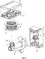
- Fig. 1ais an illustrative perspective view of a wall fixture in the form of a wall access box of a cable connection assembly according to an exemplary embodiment of the present disclosure.
- Fig. 1bis an illustrative exploded view of the access box shown in Fig. 1a.
- Fig. 1cis an illustrative view of the access box shown in Fig. 1a in use.
- Fig. Idillustrates the access box with the spool in the extended position prior to storage.
- Figs. 2a and 2bshow an illustrative perspective view and an illustrative exploded view of a cable connection portion and a spool of the access box of Fig. 1 at different view angles.
- an access box 1comprises a seat portion 11 and a cable connection portion 12 configured to be detachably mounted on the seat portion 11.
- the cable connection portion 12comprises a spool 13 on which a cable 14 (a first cable) is wound and a connector 15 (see Fig. 2a ) for coupling the cable 14 to a second access box (not shown).
- the spool 13 and the connector 15both are provided on a body 17 of the cable connection portion 12.
- the cable connection portion 12may further comprise a cover 16 covering the outer surface of the body 17 and forming the appearance of the access box 1.
- the cable 14may be pre-coupled to the connector 15.
- the seat portion 11 of the access box 1is configured to be mounted on the surface of the wall and protruded from the surface of a wall.
- the seat portion 11defines a wall mount surface 50.
- the cable connection portion 12comprises a body 17 and a cover 16 covering the outer surface of the body 17 and forming the appearance of the access box 1.
- the spool 13is provided on one side of the body 17.
- a free end of the cable 14 wound on the spool 13is coupled with a connector 15, and the connector 15 is mounted on the one side of the body 17 (see Fig. 2a ).
- Two adapters 19are provided on the other side of the body 17 opposite to the side provided with the spool 13, and the other end of the cable 14 is pre-coupled to one of the adapters 19 through a connector 18.
- a termination of a cable (a second cable) from a communication device at a user endcan be coupled to the adapter 19.
- the number of the adapters 19is not limited to the illustrated embodiment, and may be one, two or more. Although one exemplary embodiment of the access box with reference to the above drawings is described, the access box of the present disclosure is not limited to the illustrated embodiment, as long as an access box comprises a seat portion and a cable connection portion detachably mounted on the seat portion, and the cable connection portion comprises a spool on which a cable is wound.
- the mounting sleeve 4is configured to be snap-fit over a support shaft 31 of the seat portion 11 of the access box 1.
- the mounting sleeve 4receives the spool 13 with a snap-fit and allows the spool 13 to rotate for deploying the cable 14.
- the mounting sleeve 4is configured to telescope into the seat portion 11 of the access box such that the spool 13 can be stored within the seat portion 11 of the access box after cable has been unwound therefrom.
- the seat portion 11 of the wall access box 1includes a support shaft 31 with a free end, and the spool 13 is rotatably mounted onto the support shaft 31 via the mounting sleeve 4 such that the spool 13 can be axially displaced relative to the support shaft 31 from an expansion to a retraction state.
- the retraction stateis where the spool 13 is positioned in the seat portion 11.
- the expansion stateis where the spool 13 is positioned outside the seat portion 11.
- an operatorcan unspool the optical cable or fiber stored on the spool 13.
- the spool 13When the spool 13 is in the expansion state, the spool 13 can rotate along a plane generally parallel to the wall mount surface 50 of the seat portion 11.
- the access box 1includes the mounting sleeve 4 having a first end slidably connected to the spool 13 in an axial direction, that is, a direction in which the spool 13 is mounted to the support shaft 31, and an opposite second end slidably connected to the support shaft 31 in the axial direction.
- the mounting sleeve 4By displacing the mounting sleeve 4 in the axial direction along the support shaft 31, the operator may pull the spool 13 to a position outside the seat portion 11 of the access box 1 where a redundant optical cable or fiber can be easily reeled on or unreeled from the spool 13.
- the spool 13may be displaced along the support shaft 31, so as to reach the expansion state.
- the mounting sleeve 4is movably connected to the support shaft 31, being axially movable, and the first end of the mounting sleeve 4 is rotatably connected to the spool 13.
- a shape of the mounting sleeve 4is complimentary or keyed to a shape of the support shaft 31. As such, the mounting sleeve 4 is prevented from rotating relative to the support shaft 31 when the spool 13 is being rotated.
- the mounting sleeve 4has a substantially tube-like or sleeve-like structure, and is slidably mounted onto the support shaft 31. Furthermore, a plurality of protrusion receiving grooves extend in the axial direction, the grooves being formed in an inner surface of the mounting sleeve 4 or an outer surface of the support shaft 31. A plurality of complimentary slide protrusions are formed on the other of the inner surface of the mounting sleeve 4 and the outer surface of the support shaft 31. The slide protrusions are positioned in the protrusion receiving grooves when the mounting sleeve 4 is connected to the support shaft 31.
- the protrusion receiving groovesare formed in the outer surface of the support shaft 31, and the slide protrusions are formed in the inner surface of the mounting sleeve 4 adjacent to the first end.
- the mounting sleeve 4can be displaced along the axial direction, with the slide protrusions being positioned in the respective protrusion receiving grooves of the support shaft 31.
- the mounting sleeve 4is prevented from rotating around the axial direction relative to the support shaft 31 because of a blocking function of the slide protrusions.
- the slide protrusionsmay be formed in the outer surface of the support shaft 31, and the protrusion receiving grooves may be formed in the inner surface of the mounting sleeve 4 adjacent to the first end.
- the protrusion receiving grooves formed in the support shaft 31include at least one first protrusion receiving groove and at least one second protrusion receiving groove
- the slide protrusions formed on the inner surface of the mounting sleeve 4include at least one first slide protrusion 42 and at least one second slide protrusion 43.
- the spool 13has a cylindrical body 21 and flanges 22 formed at opposite ends of the cylindrical body 21.
- a notch 26may be formed on the flange 22 positioned on a first end of the reel 2 for the optical cable or fiber to pass therethrough.
- the first end of the mounting sleeve 4is positioned in a sleeve receiving passageway (not labeled) extending through the cylindrical body 21, with the mounting sleeve being axially movable.
- the cylindrical body 21has a ring-shaped protruding band 24 circumferentially positioned inside the sleeve receiving passageway on the second end of the cylindrical body 21.
- the protruding band 24is rotatably positioned over the outer surface of the mounting sleeve 4, adjacent to the first end of the mounting sleeve 4.
- An engagement portion 25is formed on the first end of the spool 13, extending outward from the flange 22, and engaging the body 17 in a snap-in manner.
- a plurality of second blocking projections 44are positioned on the first end of the mounting sleeve 4, and are configured to lock with a circumferential edge 241 of the protruding band 24 positioned proximate to the second end of the cylindrical body 21.
- the spool 13is consequently blocked from disengaging from the first end of the mounting sleeve 4 when the spool 13 is in the expansion state.
- the second blocking projections 44 and the circumferential edge 241each have a complimentary surface substantially perpendicular to the axial direction.
- a plurality of second limiting projections 242are positioned on the protruding band 24, and a circumferentially extending ring groove 45 is formed in the outer surface of the mounting sleeve 4.
- the second limiting projection 242is received in the ring groove 45 in a snap-fit manner so as to limit further displacement of the mounting sleeve 4 in the retraction direction.
- a collar 23may be positioned in the second end of the cylindrical body 21, extending inward into the sleeve receiving passageway.
- the collar 23is spaced a distance away from an inner wall of the cylindrical body 21 defining the sleeve receiving passageway to form a gap 232.
- the collar 23is positioned between the second end of the mounting sleeve 4 and the free end of the support shaft 31 so that the spool 13 can be rotated relative to the support shaft 31 and the mounting sleeve 4.
- a collar limiting projection 231is formed on the collar 23, and a complementary third limiting projection is positioned on the free end of the support shaft 31.
- the collar limiting projection 231engages with the third limiting projection in a snap-fit manner so as to limit the spool 13 from being removed from the mounting sleeve 4 when the spool 13 is in the retraction state. In this way, the spool 13 can be stably received in the seat portion 11 of the access box 1.
- the access box 1may include a mounting sleeve with a first end which is rotatably and axial-slidably connected to the support shaft, and an opposite second end which is axial-movably connected to the reel and not rotated with respect to the spool.
- the spool 13may be directly slidably connected to the support shaft.
- a plurality of protrusion receiving grooves extending in the axial directionare formed in one of an inner surface of the spool and an outer surface of the support shaft, and a plurality of slide protrusions for being slidably fitted in respective protrusion receiving grooves are formed on the other of the inner surface of the spool and the outer surface of the support shaft.
- the spool 13may be retracted into the seat portion 11 or expanded out therefrom, facilitating the maintenance and management operation on the redundant optical cable and/or fiber.
- the optical cable or fiber 14may be pre-stored in the spool 13.
- the optical cable or fiber 14may be unreeled out of the spool 13 in use and spliced or connected to other devices without calculating the length of the optical cable or fiber to be used, thereby achieving a quick deployment operation.
- the seat portion 11 of the access box 1may be mounted on various mounting walls, for example, plasterboards, with different thicknesses.
- the spool 13may still be rotatable in the seat portion under the retraction state where it is received in the seat portion.
- the spool 13may be rotatable relative to the support shaft 31 under the expansion state where it is expanded out of the seat portion 11 so that the optical cable or fiber 14 can be unreeled from the spool.
- the spool 13is configured to rotate about a plane that is generally parallel to the wall mount surface 50 defined by the seat portion 11 (and also to the mounting wall).
- the optical cable or fiber that is unwound from the spool 13may need to go through an opening in the seat portion 11 and directly into the mounting wall. It would be advantageous to provide a solution wherein the spool 13 may be rotated along a plane that is generally perpendicular or at a non-parallel angle to the mounting wall so as to limit the amount of bending stress put on the optical cable or fiber 14 when it is being unreeled toward the wall (i.e., toward the back side of the seat portion 11).
- a spool re-orientation device 52wherein the cable spool 13 may be efficiently brought to a position where the spool 13 is being rotated along a plane that is generally perpendicular or at a non-parallel angle to the mounting wall, are shown.
- the device 52defines a first mounting end or base 54 that is configured for mounting on the support shaft 31 of the seat portion 11 via the mounting sleeve 4 and a second rotation end 56 that is configured to receive the spool 13.
- the rotation end 56also utilizes a mounting sleeve similar to mounting sleeve 4 for rotatably receiving the spool 13.
- the second rotation end 56is configured to orient the spool 13 at a position that is generally perpendicular to its orientation when the spool 13 is mounted directly to the support shaft 31.
- the spool 13can rotate along a plane that is generally perpendicular to the wall mounting surface 50 of the seat portion 11 such that the optical cable or fiber 14 can be unreeled straight through the seat portion 11 and into the wall.
- the re-orientation device 52may be removed from both the support shaft 31 and the spool 13 and can be stored for later use.
- the spool 13can be placed on the mounting sleeve 4 that is around the support shaft 31 and be brought to the retracted position for storing within the seat portion 11.
- a spool re-orientation device 152may be provided as an integral part of the access box 1.
- the device 152may be configured integrally as part of a support shaft 131.
- the support shaft 131defines a plurality of telescoping sections 58 that are configured to move the spool 13 away from the seat portion 11 of the access box 1.
- the topmost telescoping section 58adefines a portion 59 that pivots relative to the rest of the telescoping sections 58 such that the spool 13, once brought to an extended configuration, can be pivoted to an orientation wherein the spool 13 rotates about a plane generally perpendicular or at a non-parallel angle to the wall mounting surface 50 of the seat portion 11 (and the wall).
- the spool reorientation device 252may be formed as part of the seat portion 11.
- the seat portion 11includes a fixed portion 254 and a slidably movable portion 256.
- the slidably movable portion 256is configured to support the spool 13 as well as the cable connection portion 12 of the access box 1.
- the movable portion 256is configured to slidably move with respect to the fixed portion 254 along a swinging path such that the movable portion 256 can bring the spool 13 from a first orientation where the spool 13 rotates along a plane parallel to the mounting surface 50 of the seat portion 11 to a second orientation where the spool 13 rotates along a plane generally perpendicular or a non-parallel angle to the mounting surface 50 of the seat portion 11.
- the movable portion 256can be slidably swung back to its initial position, and the spool 13 can be moved to its retracted position within the seat portion 11.
- the fixed portion 254 and the slidably movable portion 256 of the devicecan be configured such that the slidably movable portion 256 can stop at selected discrete positions along its path while it is being moved from the parallel-to-the-wall orientation.
- one of the discrete positionsmay be at a 45 degree angle relative to the mounting surface 50 of the seat portion 11 or the wall.
- the spool 13may rotate along planes that are not necessarily perpendicular to the mounting surface 50, such as at 45 degree angle to the mounting surface 50.
- the flanges 22 of the spool 13may be formed as frangible or breakable structures such that they can be removed before seating the spool 13 within the seat portion 11.
- the flanges 22, before, being removed,assist with the reeling and retaining of the optical cable 14 around the spool 13.
- the spool re-orientation device of the present disclosuremay be used with wall fixtures other than wall access boxes and the wall access box 1 described above is simply one example of a wall fixture with which the inventive aspects of the spool re-orientation device may be used.
- a spool re-orientation device 352is illustrated.
- the embodiment of the device 352 illustrated in Figs. 21-24is configured as a removable device such as the device 52 shown in Figs. 7-10 .
- the device 352includes features that allow the device 352 to be mounted either to the seat portion 11 of a wall access box 1 that mounts to a wall surface (see Fig. 24 ) or to a cavity mount body 301 (see Fig. 23 ) that can be mounted within a wall cavity.
- the wall fixtureis provided in the form of the wall cavity mount body 301.
- the device 352defines a base portion 303 that includes a slider 305 for expanding the cross-dimensional size of the base portion 303.
- the base portion 303 of the device 352can fit within the internal dimensions of a cavity mount body 301 as shown in Fig. 23 .
- the base portion 303assumes a shape that can intermate with the internal features of the seat portion 11 of an access box 1 as shown in Fig. 24 .
- the slider 305defines a catch portion 307 that is configured to cooperate with a protrusion 309 defined within the seat portion 11 of the access box 1 when the slider 305 is in an extended position.
- the device 352can be adjusted in size or changed in configuration.
- the slider 305may define tabs or detents 311 that interact with tabs or detents 313 provided along a slider track 315 defined by the base 303 of the device 352 to define a stop position in the extended configuration.
- the detents 311 of the slider 305may also interact with indents 317 provided at an opposite end of the slider track 315 to define a latch in the retracted position.
Landscapes
- Physics & Mathematics (AREA)
- General Physics & Mathematics (AREA)
- Optics & Photonics (AREA)
- Light Guides In General And Applications Therefor (AREA)
Description
- The present disclosure relates to alternative designs for a cable spool re-orientation device, wherein the cable spool is provided on a wall access box and is used in initially storing and then deploying the cable.
- In an optical communication network, fibers from an external optical cable are coupled to respective individual user fibers by, for example, splicing. Collectively, these fibers constitute the optical communication network. To splice different fibers together, a fiber optic device is widely applied in the optical communication network, being able to splice fibers in various mounting conditions, such as in air, in pipes and conduits, or in underground environmental conditions.
- Conventional fiber optic splicing housings may generally include a fiber storing space and a plurality of splicing device receiving spaces positioned on a tray. The fiber storing space is used to store excess and redundant fiber, and the plurality of splicing device receiving spaces are used to mount fiber splicing devices, such as mechanical splicing devices, fusion splicing devices, etc., for coupling different fibers.
- However, the fiber storing device of the conventional fiber optic splicing enclosure is not adapted to store an optical cable having a diameter larger than that of the fiber. Thereby, a predetermined length of redundant optical cable must be reserved outside the splicing enclosure according to an arrangement of the splicing enclosure and a support panel for supporting the splicing enclosure. The conventional design may have several drawbacks. If the reserved redundant optical cable is too short, it may have a disadvantageous effect on the splicing of fibers. If the reserved redundant optical cable is too long, it may be hard to maintain and manage the optical cable and its fiber.
- Attempts to address such disadvantages include the use of an external spool for pre-storing the optical cable. However, such external spools are bulky and must be accommodated by the fiber optic splicing housings that are mounted on the mounting wall.
US 2006/068633 discloses a telecommunications wall fixture comprising: (a) a first means for mounting the fixture to a wall, said first means having at least one opening and one or more guide structures; and (b) a second means for accessing the fixture, said second means having at least one cable management structure operatively associated therewith and being slidably and pivotably coupled relative to said first means via at least one of said guide structures.- The inventive features of the present disclosure have been made to overcome or alleviate at least one aspect of the above mentioned disadvantages. According to the claimed invention, these objectives are achieved by a telecommunications wall fixture according to
claim 1. - Accordingly, an object of the present disclosure relates to a telecommunications wall box that includes a body configured for mounting to a wall, the body defining a mounting surface generally parallel to the wall when mounted. A cable storage spool is rotatably mounted to the body for storage and deployment of cable. A device is used for re-orienting the rotation axis of the spool from being generally perpendicular to the mounting surface to being generally parallel or non-perpendicular to the mounting surface, wherein the spool is configured such that the spool can be stored within the body when the spool is oriented to have the rotation axis generally perpendicular to the mounting surface.
- According to the claimed invention the telecommunication wall fixture comprises a re-orientation device, the re-orientation device comprising a first end for mounting on the wall fixture, the first end configured to receive at least a portion of a shaft that is used to initially mount the spool to the wall fixture such that spool is oriented for rotation along a plane parallel to a wall mount surface of the wall fixture and a second end configured to removably receive the spool and orient the spool for rotation along a plane generally perpendicular or non-parallel to the wall mount surface.
- According to yet another aspect, the disclosure relates to a method of changing the orientation of a cable spool according to claim 5.
- The above and other features of the present disclosure will become more apparent by describing in detail exemplary embodiments thereof with reference to the accompanying drawings, in which:
Fig. 1a is an illustrative perspective view of an access box of a cable connection assembly according to an exemplary embodiment of the present invention;Fig. 1b is an illustrative exploded view of the access box;Fig. 1c is an illustrative view of the access box in use;- Fig. Id illustrates the access box with the spool in the extended position prior to storage;
Figs. 2a and 2b show an illustrative perspective view and an illustrative exploded view of the access boxes ofFigs. 1a-d at different view angles;Fig. 3 is a perspective view of the spool of the cable connection assembly;Fig. 4 is a cross-sectional view of the spool;Fig. 5 is a perspective view of a mounting sleeve of the cable connection assembly;Fig. 6 is a cross-sectional view of the mounting sleeve;Fig. 7 illustrates an exploded view showing a spool re-orientation device being used with the access box ofFigs. 1-6 ;Fig. 8 illustrates a perspective view of the access box ofFig. 7 in an assembled configuration;Fig. 9 is another perspective view of the access box ofFig. 8 ;Fig. 10 shows the spool re-orientation device in isolation;Fig. 11 illustrates another embodiment of a spool re-orientation device having features that are examples of inventive aspects in accordance with the present disclosure, the spool shown in the extended state;Fig. 12 illustrates the access box ofFig. 11 with the spool re-orientation device in the retracted/collapsed position;Fig. 13 illustrates yet another embodiment of a spool re-orientation device having features that are examples of inventive aspects in accordance with the present disclosure, the spool re-orientation device shown in the neutral position;Fig. 14 illustrates a side view of the access box ofFig. 13 ;Fig. 15 is a top view of the access box ofFig. 13 ;Fig. 16 is a front view of the access box ofFig. 13 ;Fig. 17 illustrates the access box ofFig. 13 with the spool re-orientation device in the slidably moved orientation;Fig. 18 illustrates a side view of the access box ofFig. 17 ;Fig. 19 is a top view of the access box ofFig. 17 ;Fig. 20 is a front view of the access box ofFig. 17 ;Fig. 21 illustrates another embodiment of a spool re-orientation device having features that are examples of inventive aspects in accordance with the present disclosure, a base portion of the spool re-orientation device shown in a closed position;Fig. 22 illustrates the spool re-orientation device ofFig. 21 with the base portion thereof in an extended position;Fig. 23 illustrates the spool re-orientation device ofFigs. 21-22 within a wall cavity mount body with the base portion provided in a closed position; andFig. 24 illustrates the spool-reorientation device ofFigs. 21-22 mounted within the seat portion of an access box configured for mounting on a surface, wherein the base portion of the spool re-orientation device is provided in an extended position for mounting within the access box.- Exemplary embodiments of the present disclosure will be described hereinafter in detail with reference to the attached drawings, wherein the like reference numerals refer to the like elements. The present disclosure may, however, be embodied in many different forms and should not be construed as being limited to the embodiment set forth herein; rather, these embodiments are provided so that the present disclosure will be thorough and complete, and will fully convey the concept of the disclosure to those skilled in the art.
Figs. 1-6 show illustrative views of an access box of a cable connection assembly according to an exemplary embodiment of the present disclosure. Hereafter, the access box will be described in detail with reference toFigs. 1-6 .Fig. 1a is an illustrative perspective view of a wall fixture in the form of a wall access box of a cable connection assembly according to an exemplary embodiment of the present disclosure.Fig. 1b is an illustrative exploded view of the access box shown inFig. 1a. Fig. 1c is an illustrative view of the access box shown inFig. 1a in use. Fig. Id illustrates the access box with the spool in the extended position prior to storage.Figs. 2a and 2b show an illustrative perspective view and an illustrative exploded view of a cable connection portion and a spool of the access box ofFig. 1 at different view angles.- As shown in
Figs. 1a-1d , in an exemplary embodiment, anaccess box 1 comprises aseat portion 11 and acable connection portion 12 configured to be detachably mounted on theseat portion 11. Thecable connection portion 12 comprises aspool 13 on which a cable 14 (a first cable) is wound and a connector 15 (seeFig. 2a ) for coupling thecable 14 to a second access box (not shown). Thespool 13 and theconnector 15 both are provided on abody 17 of thecable connection portion 12. Thecable connection portion 12 may further comprise acover 16 covering the outer surface of thebody 17 and forming the appearance of theaccess box 1. Also, as shown inFig. 2a , thecable 14 may be pre-coupled to theconnector 15. Theseat portion 11 of theaccess box 1 is configured to be mounted on the surface of the wall and protruded from the surface of a wall. Theseat portion 11 defines awall mount surface 50. - As shown in
Figs. 2a and 2b , thecable connection portion 12 comprises abody 17 and acover 16 covering the outer surface of thebody 17 and forming the appearance of theaccess box 1. Thespool 13 is provided on one side of thebody 17. A free end of thecable 14 wound on thespool 13 is coupled with aconnector 15, and theconnector 15 is mounted on the one side of the body 17 (seeFig. 2a ). Twoadapters 19 are provided on the other side of thebody 17 opposite to the side provided with thespool 13, and the other end of thecable 14 is pre-coupled to one of theadapters 19 through aconnector 18. A termination of a cable (a second cable) from a communication device at a user end can be coupled to theadapter 19. The number of theadapters 19 is not limited to the illustrated embodiment, and may be one, two or more. Although one exemplary embodiment of the access box with reference to the above drawings is described, the access box of the present disclosure is not limited to the illustrated embodiment, as long as an access box comprises a seat portion and a cable connection portion detachably mounted on the seat portion, and the cable connection portion comprises a spool on which a cable is wound. - Referring now to
Figs. 3-6 , thespool 13 and a mountingsleeve 4, which is configured to removably receive thespool 13, are illustrated in further detail. The mountingsleeve 4, as will be described in further detail below, is configured to be snap-fit over asupport shaft 31 of theseat portion 11 of theaccess box 1. The mountingsleeve 4 receives thespool 13 with a snap-fit and allows thespool 13 to rotate for deploying thecable 14. In the depicted exemplary embodiment, the mountingsleeve 4 is configured to telescope into theseat portion 11 of the access box such that thespool 13 can be stored within theseat portion 11 of the access box after cable has been unwound therefrom. - Still referring to
Figs 3-6 , as noted above, theseat portion 11 of thewall access box 1 includes asupport shaft 31 with a free end, and thespool 13 is rotatably mounted onto thesupport shaft 31 via the mountingsleeve 4 such that thespool 13 can be axially displaced relative to thesupport shaft 31 from an expansion to a retraction state. The retraction state is where thespool 13 is positioned in theseat portion 11. The expansion state is where thespool 13 is positioned outside theseat portion 11. When thespool 13 is in the expansion state, an operator can unspool the optical cable or fiber stored on thespool 13. When thespool 13 is in the expansion state, thespool 13 can rotate along a plane generally parallel to thewall mount surface 50 of theseat portion 11. - As noted above, the
access box 1 includes the mountingsleeve 4 having a first end slidably connected to thespool 13 in an axial direction, that is, a direction in which thespool 13 is mounted to thesupport shaft 31, and an opposite second end slidably connected to thesupport shaft 31 in the axial direction. By displacing the mountingsleeve 4 in the axial direction along thesupport shaft 31, the operator may pull thespool 13 to a position outside theseat portion 11 of theaccess box 1 where a redundant optical cable or fiber can be easily reeled on or unreeled from thespool 13. In an embodiment, thespool 13 may be displaced along thesupport shaft 31, so as to reach the expansion state. The mountingsleeve 4 is movably connected to thesupport shaft 31, being axially movable, and the first end of the mountingsleeve 4 is rotatably connected to thespool 13. A shape of the mountingsleeve 4 is complimentary or keyed to a shape of thesupport shaft 31. As such, the mountingsleeve 4 is prevented from rotating relative to thesupport shaft 31 when thespool 13 is being rotated. - Referring to
Figs. 5-6 , the mountingsleeve 4 has a substantially tube-like or sleeve-like structure, and is slidably mounted onto thesupport shaft 31. Furthermore, a plurality of protrusion receiving grooves extend in the axial direction, the grooves being formed in an inner surface of the mountingsleeve 4 or an outer surface of thesupport shaft 31. A plurality of complimentary slide protrusions are formed on the other of the inner surface of the mountingsleeve 4 and the outer surface of thesupport shaft 31. The slide protrusions are positioned in the protrusion receiving grooves when the mountingsleeve 4 is connected to thesupport shaft 31. - The protrusion receiving grooves are formed in the outer surface of the
support shaft 31, and the slide protrusions are formed in the inner surface of the mountingsleeve 4 adjacent to the first end. In this way, the mountingsleeve 4 can be displaced along the axial direction, with the slide protrusions being positioned in the respective protrusion receiving grooves of thesupport shaft 31. However, the mountingsleeve 4 is prevented from rotating around the axial direction relative to thesupport shaft 31 because of a blocking function of the slide protrusions. One of ordinary skill in the art would appreciate that the slide protrusions may be formed in the outer surface of thesupport shaft 31, and the protrusion receiving grooves may be formed in the inner surface of the mountingsleeve 4 adjacent to the first end. - Still referring to
Figs. 5-6 , the protrusion receiving grooves formed in thesupport shaft 31 include at least one first protrusion receiving groove and at least one second protrusion receiving groove, and the slide protrusions formed on the inner surface of the mountingsleeve 4 include at least onefirst slide protrusion 42 and at least onesecond slide protrusion 43. During converting thespool 13 from the retraction state to the expansion state or from the expansion state to the retraction state, thefirst slide protrusion 42 and thesecond slide protrusion 43 slide in the first protrusion receiving groove and the second protrusion receiving groove, respectively, and prevent the mountingsleeve 4 from being rotated relative to thesupport shaft 31. - In the embodiment of
Figs. 1-6 , thespool 13 has acylindrical body 21 andflanges 22 formed at opposite ends of thecylindrical body 21. Anotch 26 may be formed on theflange 22 positioned on a first end of the reel 2 for the optical cable or fiber to pass therethrough. The first end of the mountingsleeve 4 is positioned in a sleeve receiving passageway (not labeled) extending through thecylindrical body 21, with the mounting sleeve being axially movable. - The
cylindrical body 21 has a ring-shaped protrudingband 24 circumferentially positioned inside the sleeve receiving passageway on the second end of thecylindrical body 21. The protrudingband 24 is rotatably positioned over the outer surface of the mountingsleeve 4, adjacent to the first end of the mountingsleeve 4. Anengagement portion 25 is formed on the first end of thespool 13, extending outward from theflange 22, and engaging thebody 17 in a snap-in manner. - A plurality of
second blocking projections 44 are positioned on the first end of the mountingsleeve 4, and are configured to lock with acircumferential edge 241 of the protrudingband 24 positioned proximate to the second end of thecylindrical body 21. Thespool 13 is consequently blocked from disengaging from the first end of the mountingsleeve 4 when thespool 13 is in the expansion state. Thesecond blocking projections 44 and thecircumferential edge 241 each have a complimentary surface substantially perpendicular to the axial direction. - A plurality of second limiting
projections 242 are positioned on the protrudingband 24, and a circumferentially extendingring groove 45 is formed in the outer surface of the mountingsleeve 4. When thespool 13 is displaced from the retraction state to the expansion state in the expansion direction, the second limitingprojection 242 is received in thering groove 45 in a snap-fit manner so as to limit further displacement of the mountingsleeve 4 in the retraction direction. - A
collar 23 may be positioned in the second end of thecylindrical body 21, extending inward into the sleeve receiving passageway. Thecollar 23 is spaced a distance away from an inner wall of thecylindrical body 21 defining the sleeve receiving passageway to form agap 232. When thespool 13 is in the retraction state, thecollar 23 is positioned between the second end of the mountingsleeve 4 and the free end of thesupport shaft 31 so that thespool 13 can be rotated relative to thesupport shaft 31 and the mountingsleeve 4. - A
collar limiting projection 231 is formed on thecollar 23, and a complementary third limiting projection is positioned on the free end of thesupport shaft 31. Thecollar limiting projection 231 engages with the third limiting projection in a snap-fit manner so as to limit thespool 13 from being removed from the mountingsleeve 4 when thespool 13 is in the retraction state. In this way, thespool 13 can be stably received in theseat portion 11 of theaccess box 1. - Although the above embodiment describes that the mounting
sleeve 4 is not rotatable relative to thesupport shaft 31 and that thespool 13 is rotatable relative to the mountingsleeve 4, the present disclosure is not limited to this version. In another embodiment, theaccess box 1 may include a mounting sleeve with a first end which is rotatably and axial-slidably connected to the support shaft, and an opposite second end which is axial-movably connected to the reel and not rotated with respect to the spool. - In another embodiment, the
spool 13 may be directly slidably connected to the support shaft. For example, a plurality of protrusion receiving grooves extending in the axial direction are formed in one of an inner surface of the spool and an outer surface of the support shaft, and a plurality of slide protrusions for being slidably fitted in respective protrusion receiving grooves are formed on the other of the inner surface of the spool and the outer surface of the support shaft. - In the assembly described above, the
spool 13 may be retracted into theseat portion 11 or expanded out therefrom, facilitating the maintenance and management operation on the redundant optical cable and/or fiber. - Further details regarding the movable mounting of the
spool 13 to thesupport shaft 31 via the mountingsleeve 4 are described inU.S. Patent Application Publication No. 2015/0153513 , incorporated herein by reference in its entirety. - During mounting the assembly, the optical cable or
fiber 14 may be pre-stored in thespool 13. The optical cable orfiber 14 may be unreeled out of thespool 13 in use and spliced or connected to other devices without calculating the length of the optical cable or fiber to be used, thereby achieving a quick deployment operation. Theseat portion 11 of theaccess box 1 may be mounted on various mounting walls, for example, plasterboards, with different thicknesses. Also, thespool 13 may still be rotatable in the seat portion under the retraction state where it is received in the seat portion. - In addition, the
spool 13 may be rotatable relative to thesupport shaft 31 under the expansion state where it is expanded out of theseat portion 11 so that the optical cable orfiber 14 can be unreeled from the spool. - In the depicted embodiment, during unreeling of the optical cable or fiber, the
spool 13 is configured to rotate about a plane that is generally parallel to thewall mount surface 50 defined by the seat portion 11 (and also to the mounting wall). However, in certain applications, the optical cable or fiber that is unwound from thespool 13 may need to go through an opening in theseat portion 11 and directly into the mounting wall. It would be advantageous to provide a solution wherein thespool 13 may be rotated along a plane that is generally perpendicular or at a non-parallel angle to the mounting wall so as to limit the amount of bending stress put on the optical cable orfiber 14 when it is being unreeled toward the wall (i.e., toward the back side of the seat portion 11). - Referring now to
Figs. 7-20 , alternative designs for aspool re-orientation device 52, wherein thecable spool 13 may be efficiently brought to a position where thespool 13 is being rotated along a plane that is generally perpendicular or at a non-parallel angle to the mounting wall, are shown. - An example embodiment of one
such device 52 is shown inFigs. 7-10 . Thedevice 52 defines a first mounting end orbase 54 that is configured for mounting on thesupport shaft 31 of theseat portion 11 via the mountingsleeve 4 and a second rotation end 56 that is configured to receive thespool 13. Therotation end 56 also utilizes a mounting sleeve similar to mountingsleeve 4 for rotatably receiving thespool 13. Thesecond rotation end 56 is configured to orient thespool 13 at a position that is generally perpendicular to its orientation when thespool 13 is mounted directly to thesupport shaft 31. When using thedevice 52, thespool 13 can rotate along a plane that is generally perpendicular to thewall mounting surface 50 of theseat portion 11 such that the optical cable orfiber 14 can be unreeled straight through theseat portion 11 and into the wall. - When the
cable 14 has been deployed to the desired length, there-orientation device 52 may be removed from both thesupport shaft 31 and thespool 13 and can be stored for later use. Thespool 13 can be placed on the mountingsleeve 4 that is around thesupport shaft 31 and be brought to the retracted position for storing within theseat portion 11. - According to another embodiment, a
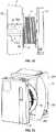
spool re-orientation device 152, rather than being a removable piece, may be provided as an integral part of theaccess box 1. For example, as shown inFigs 11-12 , thedevice 152 may be configured integrally as part of asupport shaft 131. In the embodiment shown, thesupport shaft 131 defines a plurality oftelescoping sections 58 that are configured to move thespool 13 away from theseat portion 11 of theaccess box 1. Thetopmost telescoping section 58a defines aportion 59 that pivots relative to the rest of thetelescoping sections 58 such that thespool 13, once brought to an extended configuration, can be pivoted to an orientation wherein thespool 13 rotates about a plane generally perpendicular or at a non-parallel angle to thewall mounting surface 50 of the seat portion 11 (and the wall). - According to another embodiment of a
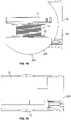
device 252 that is formed generally integrally with theaccess box 1, as shown inFigs. 13-20 , thespool reorientation device 252 may be formed as part of theseat portion 11. As shown, according to the depicted embodiment, theseat portion 11 includes a fixedportion 254 and a slidablymovable portion 256. The slidablymovable portion 256 is configured to support thespool 13 as well as thecable connection portion 12 of theaccess box 1. Themovable portion 256 is configured to slidably move with respect to the fixedportion 254 along a swinging path such that themovable portion 256 can bring thespool 13 from a first orientation where thespool 13 rotates along a plane parallel to the mountingsurface 50 of theseat portion 11 to a second orientation where thespool 13 rotates along a plane generally perpendicular or a non-parallel angle to the mountingsurface 50 of theseat portion 11. As discussed above, once thecable 14 is deployed, themovable portion 256 can be slidably swung back to its initial position, and thespool 13 can be moved to its retracted position within theseat portion 11. - It should be noted that the fixed
portion 254 and the slidablymovable portion 256 of the device can be configured such that the slidablymovable portion 256 can stop at selected discrete positions along its path while it is being moved from the parallel-to-the-wall orientation. For example, one of the discrete positions may be at a 45 degree angle relative to the mountingsurface 50 of theseat portion 11 or the wall. As such, depending upon the cable deployment need or direction, thespool 13 may rotate along planes that are not necessarily perpendicular to the mountingsurface 50, such as at 45 degree angle to the mountingsurface 50. - It should be noted that in certain embodiments (such as the embodiment shown in
Figs. 7-20 ), theflanges 22 of thespool 13 may be formed as frangible or breakable structures such that they can be removed before seating thespool 13 within theseat portion 11. Theflanges 22, before, being removed, assist with the reeling and retaining of theoptical cable 14 around thespool 13. - The spool re-orientation device of the present disclosure may be used with wall fixtures other than wall access boxes and the
wall access box 1 described above is simply one example of a wall fixture with which the inventive aspects of the spool re-orientation device may be used. - Referring now to
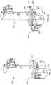
Figs. 21-24 , another embodiment of aspool re-orientation device 352 is illustrated. The embodiment of thedevice 352 illustrated inFigs. 21-24 is configured as a removable device such as thedevice 52 shown inFigs. 7-10 . However, thedevice 352 includes features that allow thedevice 352 to be mounted either to theseat portion 11 of awall access box 1 that mounts to a wall surface (seeFig. 24 ) or to a cavity mount body 301 (seeFig. 23 ) that can be mounted within a wall cavity. Thus, in the embodiment ofFig. 23 , the wall fixture is provided in the form of the wallcavity mount body 301. - Referring specifically now to
Figs. 21-22 , thedevice 352 defines abase portion 303 that includes aslider 305 for expanding the cross-dimensional size of thebase portion 303. When theslider 305 is in a closed or retracted position, thebase portion 303 of thedevice 352 can fit within the internal dimensions of acavity mount body 301 as shown inFig. 23 . When theslider 305 is in an extended position, thebase portion 303 assumes a shape that can intermate with the internal features of theseat portion 11 of anaccess box 1 as shown inFig. 24 . For example, theslider 305 defines acatch portion 307 that is configured to cooperate with aprotrusion 309 defined within theseat portion 11 of theaccess box 1 when theslider 305 is in an extended position. Thus, depending upon the mounting structure on which thespool re-orientation device 352 is going to be used, thedevice 352 can be adjusted in size or changed in configuration. - In the depicted embodiment, the
slider 305 may define tabs ordetents 311 that interact with tabs ordetents 313 provided along aslider track 315 defined by thebase 303 of thedevice 352 to define a stop position in the extended configuration. Thedetents 311 of theslider 305 may also interact withindents 317 provided at an opposite end of theslider track 315 to define a latch in the retracted position. - Although several exemplary embodiments have been shown and described, it would be appreciated by those skilled in the art that various changes or modifications may be made in these embodiments without departing from the principles of the disclosure, the scope of which is defined in the claims.
- As used herein, an element recited in the singular and proceeded with the word "a" or "an" should be understood as not excluding plural of said elements or steps, unless such exclusion is explicitly stated. Furthermore, references to "one embodiment" of the present disclosure are not intended to be interpreted as excluding the existence of additional embodiments that also incorporate the recited features. Moreover, unless explicitly stated to the contrary, embodiments "comprising" or "having" an element or a plurality of elements having a particular property may include additional such elements not having that property.
Claims (6)
- A telecommunications wall fixture (1) comprising:a seat portion (11) configured for mounting to a wall, the seat portion (11) defining a mounting surface (50) generally parallel to the wall when mounted;a cable storage spool (13) rotatably mounted to the seat portion (11) for storage and deployment of cable (14), wherein the cable storage spool (13), in a stored configuration, is stored within the seat portion (11) and the cable storage spool (13) is oriented to have a rotation axis generally perpendicular to the mounting surface (50); anda device (52, 152, 252, 352) for re-orienting the rotation axis of the spool (13) from being generally perpendicular to the mounting surface (50) to being generally non-perpendicular to the mounting surface (50), wherein the re-orientation device (52, 152, 252, 352) further comprises a first end (54) for mounting on the seat portion (11), the first end (54) configured to receive at least a portion of a shaft (31) that is used to initially mount the spool (13) to the seat portion (11) such that spool (13) is oriented for rotation along a plane parallel to the mounting surface (50) and a second end (56) configured to removably receive the spool (13) and orient the spool (13) for rotation along a plane generally non-parallel to the mounting surface (50) for deployment of cable (14).
- A telecommunications wall fixture (1) according to claim 1, wherein the re-orientation device (52, 352) is removable from the seat portion (11).
- A telecommunications wall fixture (1) according to claim 1, wherein the seat portion (11) defines an opening on the mounting surface (50) for guiding of cable (14) toward the wall.
- A telecommunications wall fixture (1) according to claim 1, wherein the device (352) defines a movable portion (305) for modifying the cross-dimensional size of the device (352).
- A method of changing the orientation of a cable spool (13) that is rotatably mounted on a seat portion (11) of a wall fixture (1) from a first orientation where the spool (13) is configured to spin along a plane parallel to a mounting surface (50) defined by the seat portion (11) of the wall fixture (1) to a second orientation where the spool (13) is configured to spin along a plane generally non-parallel to the mounting surface (50), wherein the cable spool (13), in a stored configuration, is stored within the seat portion (11) of the wall fixture (1) and the cable spool (13) is oriented to have a rotation axis generally perpendicular to the mounting surface (50) defined by the seat portion (11), the method comprising:- unlatching the spool (13) from a shaft (31) of the seat portion (11) of the wall fixture (1) when the spool (13) is in the first orientation;- placing a removable re-orientation device (52, 352) in between the spool (13) and the seat portion (11) of the wall fixture (1) after unlatching the spool (13) from the seat portion (11) of the wall fixture (1); and- latching the spool (18) to the re-orientation device (52, 352) that has been placed within the seat portion (11) of the wall fixture (1) such that the spool (13) is positioned in the second orientation, wherein the re-orientation device (52, 152, 252, 352) comprises a first end (54) for mounting on the seat portion (11), the first end (54) configured to receive at least a portion of the shaft (31) that is used to initially mount the spool (13) to the seat portion (11) such that spool (13) is oriented in the first orientation for rotation along the plane parallel to the mounting surface (50) and a second end (56) configured to removably receive the spool (13) and orient the spool (13) in the second orientation for rotation along the plane generally non-parallel to the mounting surface (50).
- A method according to claim 5, wherein the spool (13) is movable toward and away from the seat portion (11) of the wall fixture (1) when in the first orientation.
Applications Claiming Priority (3)
| Application Number | Priority Date | Filing Date | Title |
|---|---|---|---|
| US201562196014P | 2015-07-23 | 2015-07-23 | |
| US201562243880P | 2015-10-20 | 2015-10-20 | |
| PCT/US2016/043382WO2017015486A1 (en) | 2015-07-23 | 2016-07-21 | Cable spool re-orientation device for a wall box |
Publications (3)
| Publication Number | Publication Date |
|---|---|
| EP3326016A1 EP3326016A1 (en) | 2018-05-30 |
| EP3326016A4 EP3326016A4 (en) | 2019-04-17 |
| EP3326016B1true EP3326016B1 (en) | 2022-09-07 |
Family
ID=57834716
Family Applications (1)
| Application Number | Title | Priority Date | Filing Date |
|---|---|---|---|
| EP16828554.2AActiveEP3326016B1 (en) | 2015-07-23 | 2016-07-21 | Cable spool re-orientation device for a wall box |
Country Status (4)
| Country | Link |
|---|---|
| US (3) | US10330880B2 (en) |
| EP (1) | EP3326016B1 (en) |
| AU (1) | AU2016297602B2 (en) |
| WO (1) | WO2017015486A1 (en) |
Families Citing this family (5)
| Publication number | Priority date | Publication date | Assignee | Title |
|---|---|---|---|---|
| EP3326016B1 (en)* | 2015-07-23 | 2022-09-07 | Commscope Technologies LLC | Cable spool re-orientation device for a wall box |
| US10162143B1 (en)* | 2017-09-21 | 2018-12-25 | Ofs Fitel, Llc | Behind-the-wall fiber spool module |
| US10998703B1 (en)* | 2020-02-26 | 2021-05-04 | International Business Machines Corporation | Cable routing and bend radius defining tool |
| CN113109910B (en)* | 2021-04-07 | 2022-12-06 | 国网甘肃省电力公司酒泉供电公司 | Transmission optical cable fiber core combining equipment |
| US20240126040A1 (en)* | 2022-10-13 | 2024-04-18 | Corning Research & Development Corporation | Routing tool for installation of fiber optic cables and method of using same |
Family Cites Families (23)
| Publication number | Priority date | Publication date | Assignee | Title |
|---|---|---|---|---|
| US4381087A (en)* | 1981-03-17 | 1983-04-26 | Williams Loren J | Adjustable wire reel |
| JP2004303629A (en) | 2003-03-31 | 2004-10-28 | Daiwa House Ind Co Ltd | Structure of embedded type outlet |
| JP2005024978A (en) | 2003-07-03 | 2005-01-27 | Mirai Ind Co Ltd | Structure of cable drawing-out section, cable drawing-out section forming device, winding member, mounting frame, and plate |
| US7059895B2 (en)* | 2004-09-24 | 2006-06-13 | Ortronics, Inc. | Work station outlet for behind-the-wall cable management |
| US7079745B1 (en)* | 2005-02-14 | 2006-07-18 | Sbc Knowledge Ventures, L.P. | Spool assembly for absorbing slack of fiber optic jumpers routed through raceways and network equipment |
| US20080011514A1 (en) | 2006-07-14 | 2008-01-17 | Tenvera, Inc. | Optical Fiber Distribution Apparatus and Method |
| US8070112B2 (en) | 2007-01-19 | 2011-12-06 | Adc Telecommunications, Inc. | Lateral storage spool for overhead cable pathway |
| US7715679B2 (en) | 2007-05-07 | 2010-05-11 | Adc Telecommunications, Inc. | Fiber optic enclosure with external cable spool |
| US7748660B2 (en)* | 2007-06-22 | 2010-07-06 | Ofs Fitel, Llc | Fiber optic rapid spooling tool |
| US20100054680A1 (en)* | 2008-08-27 | 2010-03-04 | Lochkovic Gregory A | Optical fiber assemblies for fiber to the subscriber applications |
| US8265447B2 (en) | 2008-09-16 | 2012-09-11 | Adc Telecommunications, Inc. | Modular fiber optic enclosure with external cable spool |
| US8660397B2 (en) | 2010-04-30 | 2014-02-25 | Corning Cable Systems Llc | Multi-layer module |
| CA2877896C (en)* | 2011-06-24 | 2020-07-21 | Adc Telecommunications, Inc. | Fiber termination enclosure with modular plate assemblies |
| US9188760B2 (en)* | 2011-12-22 | 2015-11-17 | Adc Telecommunications, Inc. | Mini rapid delivery spool |
| CN104412475B (en)* | 2012-04-30 | 2019-01-15 | Adc电信公司 | Cable storage spool with center feed |
| US9126802B2 (en)* | 2012-04-30 | 2015-09-08 | Adc Telecommunications, Inc. | Payout spool with automatic cable disconnect/reconnect |
| CN202583564U (en) | 2012-05-03 | 2012-12-05 | 泰科电子(上海)有限公司 | Optical fiber splice box |
| CN202837598U (en) | 2012-08-07 | 2013-03-27 | 泰科电子(上海)有限公司 | Optical fiber connection assembly |
| CN106707434B (en) | 2012-08-07 | 2019-06-11 | 爱德奇电讯国际贸易(上海)有限公司 | Fibre junction component |
| US20150093088A1 (en)* | 2013-09-30 | 2015-04-02 | Optema Technology Limited | Fiber Optic Terminal Assemblies |
| US9459425B2 (en)* | 2013-12-20 | 2016-10-04 | Google Inc. | Spooling cable |
| EP3326016B1 (en)* | 2015-07-23 | 2022-09-07 | Commscope Technologies LLC | Cable spool re-orientation device for a wall box |
| US10359590B2 (en)* | 2016-04-04 | 2019-07-23 | Opterna Technology Limited | Fiber optic cable deployment assemblies, systems, and methods |
- 2016
- 2016-07-21EPEP16828554.2Apatent/EP3326016B1/enactiveActive
- 2016-07-21WOPCT/US2016/043382patent/WO2017015486A1/ennot_activeCeased
- 2016-07-21USUS15/747,064patent/US10330880B2/enactiveActive
- 2016-07-21AUAU2016297602Apatent/AU2016297602B2/ennot_activeCeased
- 2019
- 2019-06-18USUS16/444,376patent/US10712517B2/ennot_activeExpired - Fee Related
- 2020
- 2020-07-10USUS16/925,522patent/US11231557B2/enactiveActive
Also Published As
| Publication number | Publication date |
|---|---|
| EP3326016A1 (en) | 2018-05-30 |
| EP3326016A4 (en) | 2019-04-17 |
| WO2017015486A1 (en) | 2017-01-26 |
| US20200409007A1 (en) | 2020-12-31 |
| AU2016297602A1 (en) | 2018-02-01 |
| US20180372976A1 (en) | 2018-12-27 |
| US20190369348A1 (en) | 2019-12-05 |
| US10712517B2 (en) | 2020-07-14 |
| AU2016297602B2 (en) | 2020-12-17 |
| US11231557B2 (en) | 2022-01-25 |
| US10330880B2 (en) | 2019-06-25 |
Similar Documents
| Publication | Publication Date | Title |
|---|---|---|
| US11231557B2 (en) | Cable spool re-orientation device for a wall box | |
| US10625978B2 (en) | Cable storage spool with center feed | |
| US10183833B2 (en) | Cable spool assembly | |
| US20210072484A1 (en) | Cable storage arrangement | |
| US9594217B2 (en) | Fiber optic splicing assembly | |
| EP2707319B1 (en) | Transformable cable reel | |
| US9500831B2 (en) | Cable payout cassette with single layer cable storage area | |
| US20220212892A1 (en) | Spool with multi-position loop keeper | |
| JP6348608B2 (en) | Optical enclosure with pre-connected cable reel | |
| EP2506053A1 (en) | Optical fibre management cap coupling box | |
| US20250282572A1 (en) | Cable reel assemblies and sub-assemblies | |
| ES2953754T3 (en) | Rolled Product Dispensing Kit |
Legal Events
| Date | Code | Title | Description |
|---|---|---|---|
| STAA | Information on the status of an ep patent application or granted ep patent | Free format text:STATUS: THE INTERNATIONAL PUBLICATION HAS BEEN MADE | |
| PUAI | Public reference made under article 153(3) epc to a published international application that has entered the european phase | Free format text:ORIGINAL CODE: 0009012 | |
| STAA | Information on the status of an ep patent application or granted ep patent | Free format text:STATUS: REQUEST FOR EXAMINATION WAS MADE | |
| 17P | Request for examination filed | Effective date:20180221 | |
| AK | Designated contracting states | Kind code of ref document:A1 Designated state(s):AL AT BE BG CH CY CZ DE DK EE ES FI FR GB GR HR HU IE IS IT LI LT LU LV MC MK MT NL NO PL PT RO RS SE SI SK SM TR | |
| AX | Request for extension of the european patent | Extension state:BA ME | |
| DAV | Request for validation of the european patent (deleted) | ||
| DAX | Request for extension of the european patent (deleted) | ||
| A4 | Supplementary search report drawn up and despatched | Effective date:20190315 | |
| RIC1 | Information provided on ipc code assigned before grant | Ipc:G02B 6/44 20060101AFI20190311BHEP | |
| STAA | Information on the status of an ep patent application or granted ep patent | Free format text:STATUS: EXAMINATION IS IN PROGRESS | |
| 17Q | First examination report despatched | Effective date:20210810 | |
| GRAP | Despatch of communication of intention to grant a patent | Free format text:ORIGINAL CODE: EPIDOSNIGR1 | |
| STAA | Information on the status of an ep patent application or granted ep patent | Free format text:STATUS: GRANT OF PATENT IS INTENDED | |
| INTG | Intention to grant announced | Effective date:20220210 | |
| GRAS | Grant fee paid | Free format text:ORIGINAL CODE: EPIDOSNIGR3 | |
| GRAA | (expected) grant | Free format text:ORIGINAL CODE: 0009210 | |
| STAA | Information on the status of an ep patent application or granted ep patent | Free format text:STATUS: THE PATENT HAS BEEN GRANTED | |
| AK | Designated contracting states | Kind code of ref document:B1 Designated state(s):AL AT BE BG CH CY CZ DE DK EE ES FI FR GB GR HR HU IE IS IT LI LT LU LV MC MK MT NL NO PL PT RO RS SE SI SK SM TR | |
| REG | Reference to a national code | Ref country code:GB Ref legal event code:FG4D | |
| REG | Reference to a national code | Ref country code:CH Ref legal event code:EP Ref country code:AT Ref legal event code:REF Ref document number:1517535 Country of ref document:AT Kind code of ref document:T Effective date:20220915 | |
| REG | Reference to a national code | Ref country code:DE Ref legal event code:R096 Ref document number:602016074881 Country of ref document:DE | |
| REG | Reference to a national code | Ref country code:IE Ref legal event code:FG4D | |
| REG | Reference to a national code | Ref country code:LT Ref legal event code:MG9D | |
| REG | Reference to a national code | Ref country code:NL Ref legal event code:MP Effective date:20220907 | |
| PG25 | Lapsed in a contracting state [announced via postgrant information from national office to epo] | Ref country code:SE Free format text:LAPSE BECAUSE OF FAILURE TO SUBMIT A TRANSLATION OF THE DESCRIPTION OR TO PAY THE FEE WITHIN THE PRESCRIBED TIME-LIMIT Effective date:20220907 Ref country code:RS Free format text:LAPSE BECAUSE OF FAILURE TO SUBMIT A TRANSLATION OF THE DESCRIPTION OR TO PAY THE FEE WITHIN THE PRESCRIBED TIME-LIMIT Effective date:20220907 Ref country code:NO Free format text:LAPSE BECAUSE OF FAILURE TO SUBMIT A TRANSLATION OF THE DESCRIPTION OR TO PAY THE FEE WITHIN THE PRESCRIBED TIME-LIMIT Effective date:20221207 Ref country code:LV Free format text:LAPSE BECAUSE OF FAILURE TO SUBMIT A TRANSLATION OF THE DESCRIPTION OR TO PAY THE FEE WITHIN THE PRESCRIBED TIME-LIMIT Effective date:20220907 Ref country code:LT Free format text:LAPSE BECAUSE OF FAILURE TO SUBMIT A TRANSLATION OF THE DESCRIPTION OR TO PAY THE FEE WITHIN THE PRESCRIBED TIME-LIMIT Effective date:20220907 Ref country code:FI Free format text:LAPSE BECAUSE OF FAILURE TO SUBMIT A TRANSLATION OF THE DESCRIPTION OR TO PAY THE FEE WITHIN THE PRESCRIBED TIME-LIMIT Effective date:20220907 | |
| REG | Reference to a national code | Ref country code:AT Ref legal event code:MK05 Ref document number:1517535 Country of ref document:AT Kind code of ref document:T Effective date:20220907 | |
| PG25 | Lapsed in a contracting state [announced via postgrant information from national office to epo] | Ref country code:HR Free format text:LAPSE BECAUSE OF FAILURE TO SUBMIT A TRANSLATION OF THE DESCRIPTION OR TO PAY THE FEE WITHIN THE PRESCRIBED TIME-LIMIT Effective date:20220907 Ref country code:GR Free format text:LAPSE BECAUSE OF FAILURE TO SUBMIT A TRANSLATION OF THE DESCRIPTION OR TO PAY THE FEE WITHIN THE PRESCRIBED TIME-LIMIT Effective date:20221208 | |
| PG25 | Lapsed in a contracting state [announced via postgrant information from national office to epo] | Ref country code:SM Free format text:LAPSE BECAUSE OF FAILURE TO SUBMIT A TRANSLATION OF THE DESCRIPTION OR TO PAY THE FEE WITHIN THE PRESCRIBED TIME-LIMIT Effective date:20220907 Ref country code:RO Free format text:LAPSE BECAUSE OF FAILURE TO SUBMIT A TRANSLATION OF THE DESCRIPTION OR TO PAY THE FEE WITHIN THE PRESCRIBED TIME-LIMIT Effective date:20220907 Ref country code:PT Free format text:LAPSE BECAUSE OF FAILURE TO SUBMIT A TRANSLATION OF THE DESCRIPTION OR TO PAY THE FEE WITHIN THE PRESCRIBED TIME-LIMIT Effective date:20230109 Ref country code:ES Free format text:LAPSE BECAUSE OF FAILURE TO SUBMIT A TRANSLATION OF THE DESCRIPTION OR TO PAY THE FEE WITHIN THE PRESCRIBED TIME-LIMIT Effective date:20220907 Ref country code:CZ Free format text:LAPSE BECAUSE OF FAILURE TO SUBMIT A TRANSLATION OF THE DESCRIPTION OR TO PAY THE FEE WITHIN THE PRESCRIBED TIME-LIMIT Effective date:20220907 Ref country code:AT Free format text:LAPSE BECAUSE OF FAILURE TO SUBMIT A TRANSLATION OF THE DESCRIPTION OR TO PAY THE FEE WITHIN THE PRESCRIBED TIME-LIMIT Effective date:20220907 | |
| PG25 | Lapsed in a contracting state [announced via postgrant information from national office to epo] | Ref country code:SK Free format text:LAPSE BECAUSE OF FAILURE TO SUBMIT A TRANSLATION OF THE DESCRIPTION OR TO PAY THE FEE WITHIN THE PRESCRIBED TIME-LIMIT Effective date:20220907 Ref country code:PL Free format text:LAPSE BECAUSE OF FAILURE TO SUBMIT A TRANSLATION OF THE DESCRIPTION OR TO PAY THE FEE WITHIN THE PRESCRIBED TIME-LIMIT Effective date:20220907 Ref country code:IS Free format text:LAPSE BECAUSE OF FAILURE TO SUBMIT A TRANSLATION OF THE DESCRIPTION OR TO PAY THE FEE WITHIN THE PRESCRIBED TIME-LIMIT Effective date:20230107 Ref country code:EE Free format text:LAPSE BECAUSE OF FAILURE TO SUBMIT A TRANSLATION OF THE DESCRIPTION OR TO PAY THE FEE WITHIN THE PRESCRIBED TIME-LIMIT Effective date:20220907 | |
| REG | Reference to a national code | Ref country code:DE Ref legal event code:R097 Ref document number:602016074881 Country of ref document:DE | |
| PG25 | Lapsed in a contracting state [announced via postgrant information from national office to epo] | Ref country code:NL Free format text:LAPSE BECAUSE OF FAILURE TO SUBMIT A TRANSLATION OF THE DESCRIPTION OR TO PAY THE FEE WITHIN THE PRESCRIBED TIME-LIMIT Effective date:20220907 Ref country code:AL Free format text:LAPSE BECAUSE OF FAILURE TO SUBMIT A TRANSLATION OF THE DESCRIPTION OR TO PAY THE FEE WITHIN THE PRESCRIBED TIME-LIMIT Effective date:20220907 | |
| PLBE | No opposition filed within time limit | Free format text:ORIGINAL CODE: 0009261 | |
| STAA | Information on the status of an ep patent application or granted ep patent | Free format text:STATUS: NO OPPOSITION FILED WITHIN TIME LIMIT | |
| PG25 | Lapsed in a contracting state [announced via postgrant information from national office to epo] | Ref country code:DK Free format text:LAPSE BECAUSE OF FAILURE TO SUBMIT A TRANSLATION OF THE DESCRIPTION OR TO PAY THE FEE WITHIN THE PRESCRIBED TIME-LIMIT Effective date:20220907 | |
| 26N | No opposition filed | Effective date:20230608 | |
| PG25 | Lapsed in a contracting state [announced via postgrant information from national office to epo] | Ref country code:SI Free format text:LAPSE BECAUSE OF FAILURE TO SUBMIT A TRANSLATION OF THE DESCRIPTION OR TO PAY THE FEE WITHIN THE PRESCRIBED TIME-LIMIT Effective date:20220907 | |
| REG | Reference to a national code | Ref country code:DE Ref legal event code:R119 Ref document number:602016074881 Country of ref document:DE | |
| PG25 | Lapsed in a contracting state [announced via postgrant information from national office to epo] | Ref country code:MC Free format text:LAPSE BECAUSE OF FAILURE TO SUBMIT A TRANSLATION OF THE DESCRIPTION OR TO PAY THE FEE WITHIN THE PRESCRIBED TIME-LIMIT Effective date:20220907 | |
| PG25 | Lapsed in a contracting state [announced via postgrant information from national office to epo] | Ref country code:MC Free format text:LAPSE BECAUSE OF FAILURE TO SUBMIT A TRANSLATION OF THE DESCRIPTION OR TO PAY THE FEE WITHIN THE PRESCRIBED TIME-LIMIT Effective date:20220907 | |
| REG | Reference to a national code | Ref country code:CH Ref legal event code:PL | |
| REG | Reference to a national code | Ref country code:BE Ref legal event code:MM Effective date:20230731 | |
| PG25 | Lapsed in a contracting state [announced via postgrant information from national office to epo] | Ref country code:LU Free format text:LAPSE BECAUSE OF NON-PAYMENT OF DUE FEES Effective date:20230721 | |
| GBPC | Gb: european patent ceased through non-payment of renewal fee | Effective date:20230721 | |
| PG25 | Lapsed in a contracting state [announced via postgrant information from national office to epo] | Ref country code:LU Free format text:LAPSE BECAUSE OF NON-PAYMENT OF DUE FEES Effective date:20230721 | |
| REG | Reference to a national code | Ref country code:IE Ref legal event code:MM4A | |
| PG25 | Lapsed in a contracting state [announced via postgrant information from national office to epo] | Ref country code:DE Free format text:LAPSE BECAUSE OF NON-PAYMENT OF DUE FEES Effective date:20240201 Ref country code:CH Free format text:LAPSE BECAUSE OF NON-PAYMENT OF DUE FEES Effective date:20230731 Ref country code:GB Free format text:LAPSE BECAUSE OF NON-PAYMENT OF DUE FEES Effective date:20230721 | |
| PG25 | Lapsed in a contracting state [announced via postgrant information from national office to epo] | Ref country code:IT Free format text:LAPSE BECAUSE OF FAILURE TO SUBMIT A TRANSLATION OF THE DESCRIPTION OR TO PAY THE FEE WITHIN THE PRESCRIBED TIME-LIMIT Effective date:20220907 Ref country code:FR Free format text:LAPSE BECAUSE OF NON-PAYMENT OF DUE FEES Effective date:20230731 Ref country code:BE Free format text:LAPSE BECAUSE OF NON-PAYMENT OF DUE FEES Effective date:20230731 | |
| PG25 | Lapsed in a contracting state [announced via postgrant information from national office to epo] | Ref country code:IE Free format text:LAPSE BECAUSE OF NON-PAYMENT OF DUE FEES Effective date:20230721 | |
| PG25 | Lapsed in a contracting state [announced via postgrant information from national office to epo] | Ref country code:IE Free format text:LAPSE BECAUSE OF NON-PAYMENT OF DUE FEES Effective date:20230721 | |
| PG25 | Lapsed in a contracting state [announced via postgrant information from national office to epo] | Ref country code:BG Free format text:LAPSE BECAUSE OF FAILURE TO SUBMIT A TRANSLATION OF THE DESCRIPTION OR TO PAY THE FEE WITHIN THE PRESCRIBED TIME-LIMIT Effective date:20220907 | |
| PG25 | Lapsed in a contracting state [announced via postgrant information from national office to epo] | Ref country code:BG Free format text:LAPSE BECAUSE OF FAILURE TO SUBMIT A TRANSLATION OF THE DESCRIPTION OR TO PAY THE FEE WITHIN THE PRESCRIBED TIME-LIMIT Effective date:20220907 | |
| PG25 | Lapsed in a contracting state [announced via postgrant information from national office to epo] | Ref country code:CY Free format text:LAPSE BECAUSE OF FAILURE TO SUBMIT A TRANSLATION OF THE DESCRIPTION OR TO PAY THE FEE WITHIN THE PRESCRIBED TIME-LIMIT; INVALID AB INITIO Effective date:20160721 | |
| PG25 | Lapsed in a contracting state [announced via postgrant information from national office to epo] | Ref country code:HU Free format text:LAPSE BECAUSE OF FAILURE TO SUBMIT A TRANSLATION OF THE DESCRIPTION OR TO PAY THE FEE WITHIN THE PRESCRIBED TIME-LIMIT; INVALID AB INITIO Effective date:20160721 |