EP3324855B1 - Device for securing heart valve leaflets - Google Patents
Device for securing heart valve leafletsDownload PDFInfo
- Publication number
- EP3324855B1 EP3324855B1EP16828665.6AEP16828665AEP3324855B1EP 3324855 B1EP3324855 B1EP 3324855B1EP 16828665 AEP16828665 AEP 16828665AEP 3324855 B1EP3324855 B1EP 3324855B1
- Authority
- EP
- European Patent Office
- Prior art keywords
- distal
- proximal
- plate
- guidewire
- heart
- Prior art date
- Legal status (The legal status is an assumption and is not a legal conclusion. Google has not performed a legal analysis and makes no representation as to the accuracy of the status listed.)
- Active
Links
Images


Classifications
- A—HUMAN NECESSITIES
- A61—MEDICAL OR VETERINARY SCIENCE; HYGIENE
- A61F—FILTERS IMPLANTABLE INTO BLOOD VESSELS; PROSTHESES; DEVICES PROVIDING PATENCY TO, OR PREVENTING COLLAPSING OF, TUBULAR STRUCTURES OF THE BODY, e.g. STENTS; ORTHOPAEDIC, NURSING OR CONTRACEPTIVE DEVICES; FOMENTATION; TREATMENT OR PROTECTION OF EYES OR EARS; BANDAGES, DRESSINGS OR ABSORBENT PADS; FIRST-AID KITS
- A61F2/00—Filters implantable into blood vessels; Prostheses, i.e. artificial substitutes or replacements for parts of the body; Appliances for connecting them with the body; Devices providing patency to, or preventing collapsing of, tubular structures of the body, e.g. stents
- A61F2/02—Prostheses implantable into the body
- A61F2/24—Heart valves ; Vascular valves, e.g. venous valves; Heart implants, e.g. passive devices for improving the function of the native valve or the heart muscle; Transmyocardial revascularisation [TMR] devices; Valves implantable in the body
- A61F2/2427—Devices for manipulating or deploying heart valves during implantation
- A—HUMAN NECESSITIES
- A61—MEDICAL OR VETERINARY SCIENCE; HYGIENE
- A61B—DIAGNOSIS; SURGERY; IDENTIFICATION
- A61B17/00—Surgical instruments, devices or methods
- A61B17/12—Surgical instruments, devices or methods for ligaturing or otherwise compressing tubular parts of the body, e.g. blood vessels or umbilical cord
- A61B17/122—Clamps or clips, e.g. for the umbilical cord
- A—HUMAN NECESSITIES
- A61—MEDICAL OR VETERINARY SCIENCE; HYGIENE
- A61B—DIAGNOSIS; SURGERY; IDENTIFICATION
- A61B17/00—Surgical instruments, devices or methods
- A61B17/064—Surgical staples, i.e. penetrating the tissue
- A61B17/0643—Surgical staples, i.e. penetrating the tissue with separate closing member, e.g. for interlocking with staple
- A—HUMAN NECESSITIES
- A61—MEDICAL OR VETERINARY SCIENCE; HYGIENE
- A61F—FILTERS IMPLANTABLE INTO BLOOD VESSELS; PROSTHESES; DEVICES PROVIDING PATENCY TO, OR PREVENTING COLLAPSING OF, TUBULAR STRUCTURES OF THE BODY, e.g. STENTS; ORTHOPAEDIC, NURSING OR CONTRACEPTIVE DEVICES; FOMENTATION; TREATMENT OR PROTECTION OF EYES OR EARS; BANDAGES, DRESSINGS OR ABSORBENT PADS; FIRST-AID KITS
- A61F2/00—Filters implantable into blood vessels; Prostheses, i.e. artificial substitutes or replacements for parts of the body; Appliances for connecting them with the body; Devices providing patency to, or preventing collapsing of, tubular structures of the body, e.g. stents
- A61F2/02—Prostheses implantable into the body
- A61F2/24—Heart valves ; Vascular valves, e.g. venous valves; Heart implants, e.g. passive devices for improving the function of the native valve or the heart muscle; Transmyocardial revascularisation [TMR] devices; Valves implantable in the body
- A61F2/2442—Annuloplasty rings or inserts for correcting the valve shape; Implants for improving the function of a native heart valve
- A61F2/246—Devices for obstructing a leak through a native valve in a closed condition
- A—HUMAN NECESSITIES
- A61—MEDICAL OR VETERINARY SCIENCE; HYGIENE
- A61B—DIAGNOSIS; SURGERY; IDENTIFICATION
- A61B17/00—Surgical instruments, devices or methods
- A61B17/12—Surgical instruments, devices or methods for ligaturing or otherwise compressing tubular parts of the body, e.g. blood vessels or umbilical cord
- A61B17/128—Surgical instruments, devices or methods for ligaturing or otherwise compressing tubular parts of the body, e.g. blood vessels or umbilical cord for applying or removing clamps or clips
- A61B17/1285—Surgical instruments, devices or methods for ligaturing or otherwise compressing tubular parts of the body, e.g. blood vessels or umbilical cord for applying or removing clamps or clips for minimally invasive surgery
- A—HUMAN NECESSITIES
- A61—MEDICAL OR VETERINARY SCIENCE; HYGIENE
- A61B—DIAGNOSIS; SURGERY; IDENTIFICATION
- A61B17/00—Surgical instruments, devices or methods
- A61B17/00234—Surgical instruments, devices or methods for minimally invasive surgery
- A61B2017/00238—Type of minimally invasive operation
- A61B2017/00243—Type of minimally invasive operation cardiac
- A—HUMAN NECESSITIES
- A61—MEDICAL OR VETERINARY SCIENCE; HYGIENE
- A61B—DIAGNOSIS; SURGERY; IDENTIFICATION
- A61B17/00—Surgical instruments, devices or methods
- A61B2017/00477—Coupling
- A—HUMAN NECESSITIES
- A61—MEDICAL OR VETERINARY SCIENCE; HYGIENE
- A61B—DIAGNOSIS; SURGERY; IDENTIFICATION
- A61B17/00—Surgical instruments, devices or methods
- A61B2017/00535—Surgical instruments, devices or methods pneumatically or hydraulically operated
- A61B2017/00557—Surgical instruments, devices or methods pneumatically or hydraulically operated inflatable
- A—HUMAN NECESSITIES
- A61—MEDICAL OR VETERINARY SCIENCE; HYGIENE
- A61B—DIAGNOSIS; SURGERY; IDENTIFICATION
- A61B17/00—Surgical instruments, devices or methods
- A61B17/02—Surgical instruments, devices or methods for holding wounds open, e.g. retractors; Tractors
- A61B2017/0237—Surgical instruments, devices or methods for holding wounds open, e.g. retractors; Tractors for heart surgery
- A61B2017/0243—Surgical instruments, devices or methods for holding wounds open, e.g. retractors; Tractors for heart surgery for immobilizing local areas of the heart, e.g. while it beats
- A—HUMAN NECESSITIES
- A61—MEDICAL OR VETERINARY SCIENCE; HYGIENE
- A61B—DIAGNOSIS; SURGERY; IDENTIFICATION
- A61B17/00—Surgical instruments, devices or methods
- A61B17/22—Implements for squeezing-off ulcers or the like on inner organs of the body; Implements for scraping-out cavities of body organs, e.g. bones; for invasive removal or destruction of calculus using mechanical vibrations; for removing obstructions in blood vessels, not otherwise provided for
- A61B2017/22038—Implements for squeezing-off ulcers or the like on inner organs of the body; Implements for scraping-out cavities of body organs, e.g. bones; for invasive removal or destruction of calculus using mechanical vibrations; for removing obstructions in blood vessels, not otherwise provided for with a guide wire
- A61B2017/22042—Details of the tip of the guide wire
- A61B2017/22044—Details of the tip of the guide wire with a pointed tip
- A—HUMAN NECESSITIES
- A61—MEDICAL OR VETERINARY SCIENCE; HYGIENE
- A61B—DIAGNOSIS; SURGERY; IDENTIFICATION
- A61B17/00—Surgical instruments, devices or methods
- A61B17/30—Surgical pincettes, i.e. surgical tweezers without pivotal connections
- A61B2017/306—Surgical pincettes, i.e. surgical tweezers without pivotal connections holding by means of suction
- A—HUMAN NECESSITIES
- A61—MEDICAL OR VETERINARY SCIENCE; HYGIENE
- A61F—FILTERS IMPLANTABLE INTO BLOOD VESSELS; PROSTHESES; DEVICES PROVIDING PATENCY TO, OR PREVENTING COLLAPSING OF, TUBULAR STRUCTURES OF THE BODY, e.g. STENTS; ORTHOPAEDIC, NURSING OR CONTRACEPTIVE DEVICES; FOMENTATION; TREATMENT OR PROTECTION OF EYES OR EARS; BANDAGES, DRESSINGS OR ABSORBENT PADS; FIRST-AID KITS
- A61F2/00—Filters implantable into blood vessels; Prostheses, i.e. artificial substitutes or replacements for parts of the body; Appliances for connecting them with the body; Devices providing patency to, or preventing collapsing of, tubular structures of the body, e.g. stents
- A61F2/02—Prostheses implantable into the body
- A61F2/24—Heart valves ; Vascular valves, e.g. venous valves; Heart implants, e.g. passive devices for improving the function of the native valve or the heart muscle; Transmyocardial revascularisation [TMR] devices; Valves implantable in the body
- A61F2/2442—Annuloplasty rings or inserts for correcting the valve shape; Implants for improving the function of a native heart valve
- A61F2/2466—Delivery devices therefor
Definitions
- the present disclosurerelates to devices and methods for treating regurgitation in a heart valve.
- Tricuspid regurgitationis a disorder in which this valve does not close tight enough. This problem causes blood to flow backward into the right upper heart chamber (atrium) when the right lower heart chamber (ventricle) contracts. Tricuspid regurgitation is leakage of blood backwards through the tricuspid valve each time the right ventricle contracts. Tricuspid regurgitation usually results from an enlarged lower heart chamber (called the ventricle) or from any other condition that constrains the blood flow from the right ventricle to the lungs.
- valve repairis the most common surgical treatment for tricuspid valve disease. Tricuspid valve repair can be done alone or in combination with treatments for other heart problems.
- Tricuspid valve repair using an annuloplasty ringis a common surgical approach for tricuspid regurgitation and may be performed for primary tricuspid disease or for combined cases with other valve surgery (mitral, aortic).
- Traditional tricuspid valve repairis an open-heart procedure performed through a 152 - 203mm (6 - 8 inch) incision through the breastbone (sternum).
- WO02/034167discloses a heart valve prosthesis according to the preamble of claim 1. According to the present invention, such a prosthesis is characterised by the characterising features of claim 1.
- This devicerepresents an endovascular method of reducing tricuspid regurgitation in patients with severe tricuspid regurgitation.
- This deviceis intended to be delivered preferably through the right internal jugular vein due to anatomical considerations, but may also be delivered through the left internal jugular vein or via the inferior vena cava.
- FIG. 1Ais a schematic representation of a heart 10 in normal diastole.
- FIG. 1Brepresents the heart 10 in normal systole.
- the heart 10consists of four chambers and the tricuspid valve 12 is interposed between the right atrium 14 and the right ventricle 16.
- the present disclosuremay represent a single point fixation between two leaflet edges of either two or three leaflets, or complete edge to edge fixation of the coaptation edges of two or three leaflets, or some combination of these methods.
- the right internal jugular vein(not shown) is preferable for delivery due to its most direct placement above the tricuspid valve 12.
- the devices and methods herein disclosedmay be delivered through the left internal jugular vein or the inferior vena cava.
- Some aspects of the present disclosureencompass a method of delivering to the ventricular side of the tricuspid valve 12, and steering with a steerable catheter to the desired leaflet coaptation point, an anchor that can include an attached and externalized guidewire or suture that is configured to secure the coaptation edge of two tricuspid leaflets at the ventricular surface.
- the externalized guidewire or suturecan possess sufficient torsional rigidity to allow rotational control of the distal anchor.
- Tensioncan then be applied through the attached guidewire or suture to the distal anchor in the ventricular to atrial direction so that the coaptation edge of the two leaflets of interest may be brought closer together or, in some cases, forced closed.
- a means of then securing the leaflet coaptation edgescan then be employed to cause the two edges to become fixed together. This procedure can then be repeated as needed to reduce the amount of tricuspid regurgitation.
- FIG. 2depicts a non-limiting exemplary embodiment of a device according to the invention.
- the device 20 and variations discussed belowcomprise a heart valve prosthesis.
- the device 20includes two rigid or semi-rigid plates, referred to as the distal plate 22 and the proximal plate 24.
- the distal and proximal plates 22, 24can sandwich the tricuspid leaflet edges and cause the entrapped edges to become fixed together.
- the distal and proximal plates 22, 24have a central portion 128 and a peripheral portion 130.
- the tricuspid leaflet edgesare held between the peripheral portions 130 of the distal and proximal plates 22, 24, while the central portion 128 of the plates 22, 24 are secured together by a connector 126 (shown in FIG. 5B ).
- the connector 126can be disposed across a gap between the distal and proximal plates 22, 24.
- the distal and proximal plates 22, 24can be aligned using alignment features (not shown), and locked together with a locking clip (shown in FIGS. 5A-C ), thereby forming a durable fixation device.
- the distal and proximal plates 22, 24may or may not feature a lengthwise curvature (not shown) as in a leaf spring to cause additional spring force to act to secure the leaflet between the plates.
- FIGS. 3A and 3Bdepict a side view and a top view of a non-limiting exemplary embodiment of a distal plate 22.
- the distal plate 22can be a rectangular plate comprised of metal (e.g., stainless steel, titanium, or titanium-containing alloy) or polymer.
- the distal plate 22may incorporate slots 26 that facilitate alignment and fixation with the proximal plate 24.
- a distal guidewire 30 or suture that is externalized from the patientmay be attached to the distal plate 22 to allow traction to be applied to the distal plate 22.
- the distal guidewire 30can be configured to provide rotational control of the distal plate 22.
- the distal plate 22may or may not include a compliant material layer (not shown) bonded to the surface 32 of the distal plate 22 at the point of contact with the tricuspid leaflets.
- the distal guidewire 30 or suturecan be mounted slightly off center along the long axis of the distal plate 22 on a pivoting anchor 34, which can allow the distal plate 22 to be rotated such that its long axis is parallel to the distal guidewire 30 or suture.
- FIG. 3Cshows a side view of the distal plate 22 rotated such that its long axis is parallel to the distal guidewire 30.
- the distal plate 22may interface with a pledget 38.
- a non-limiting exemplary embodiment of a pledget 38is shown in FIG. 3C and is discussed below.
- the distal plate 22may provide a sturdy mechanical backing for the pledget 38.
- FIG. 3Ddepicts a top view of a non-limiting exemplary embodiment of a pledget 38.
- the pledget 38can be made of woven or non-woven fibrous material such as Dacron or Gore-Tex or a bulk material such as silicone rubber.
- the pledget 38can include a notch 39 cut into the material to allow the distal guidewire 30 to fold flat against the distal plate 22 as shown in FIG. 3C .
- the pledget 38can be configured to enhance securement of the tricuspid valve between the distal and proximal plates 22, 24. In some aspects, the pledget 38 may act as a cushion.
- the pledget 38may receive spikes on the proximal plate 24 that pass through the valve leaflet and penetrate the pledget 38 as the proximal plate 24 is pushed toward the distal plate 22.
- the locking clippasses through a circular cut-out 37 of the pledget 38.
- the locking clipclips completely outside the perimeter of the plates in one embodiment. Some embodiments incorporate a clip that penetrates the pledget 38.
- FIGS. 4A-Cdepict a side view, a bottom view, and an end view of a non-limiting exemplary embodiment of a proximal plate 24.
- the proximal plate 24can be a rectangular plate comprised of metal or polymer.
- the proximal plate 24may incorporate a protruding feature (not shown) that mates and self-aligns with the distal plate 22.
- the proximal plate 24may include slots 36 that align with the slots 26 of the distal plate 22, thereby facilitating the passage of a barbed locking clip to fix the distal and proximal plates 22, 24 together.
- the proximal plate 24can include a feature 40 (e.g., through hole) to allow passage of the distal guidewire 30 or suture from the distal plate 22.
- the proximal plate 24may have an affixed proximal guidewire 42 or suture that is externalized from the patient to allow traction and rotational control to be applied to the proximal plate 24.
- the proximal guidewire 42 or suturecan be mounted centrally on the proximal plate 22 on a pivoting anchor 44.
- the pivoting anchor 44may be configured to allow the proximal plate 24 to be rotated such that its long axis is parallel to the proximal guidewire 42 or suture, as shown in FIG. 4D .
- a friction enhancing featuresuch as a series of teeth, bumps, or surface roughening may or may not be applied to the surface of the distal or proximal plate 22, 24 that contacts the tricuspid leaflets.
- the proximal plate 24can include one or more grooves 43 a,b.
- the grooves 43 a,bcan extend more than halfway across the distal plate 24 and overlap with one another so that when the proximal plate 24 and its guidewire 42 are in the deployed configuration (i.e., long axis of the proximal plate 24 is perpendicular to the proximal guidewire 42), there exists a hole 40 through which the proximal end of the distal guidewire 30 can be threaded.
- the grooves 43 a,bcan allow the distal guidewire 30 to clear the ends of the proximal plate 24.
- the overlapping grooves 43 a,bcan form a through hole that allows the proximal plate 24 to be advanced lengthwise over the distal guidewire 30, through a catheter, to the right atrium where the proximal plate 24 can be rotated 90 degrees relative to the proximal guidewire 42 to bring the proximal plate 24 into the deployed configuration.
- the slot configurationallows the distal guidewire 30 to clear the proximal plate 24 so that it now passes only through the hole 40.
- FIGS. 5A-Cdepict a top view, an end view, and a side view of a non-limiting exemplary embodiment of a connector 126.
- the connector 126is a locking clip 50.
- the locking clip 50can be a rigid part made of metal or polymer.
- the locking clip 50includes an open end 120 and a closed end 122. As described below, the open end 120 can be advanced initially over the proximal plate 24 and subsequently over the distal plate 22.
- the locking clipmay include spaced apart arms 51 that extend from a bridge portion 56.
- the arms 51can include raised features 52 that can be threaded through the concentric slots 26, 36 of the distal and proximal plates 22, 24.
- the arms 51can be pushed over the edges of the distal and proximal plates 22, 24, as described below.
- the connector 126includes an aperture 124 configured to receive a guidewire.
- the locking clip 50can include a central hole 54 to allow passage of the distal and proximal guidewires 30, 42 that connect to the distal and proximal plates 22, 24.
- the raised features 52may incorporate a series of barbs on the ends such that passage of the locking clip 50 through the distal and proximal plates 22, 24 can proceed in one direction only.
- the bridge portion 56prevents the locking clip 50 from passing through the concentric slots 26, 36 of the distal and proximal plates 22, 24.
- the bridge portion 56 of the locking clip 50may also integrate a compliant material where the locking clip 50 contacts the proximal plate 24.
- the compliant materialcan act as a spring to push the proximal plate 24 against the distal plate 22.
- the barbsgrip the ventricular side of the distal plate 22, thereby causing the bridge portion 56 to apply a retaining force against the atrial side of the proximal plate 22, the effect of which is similar to a rivet holding the distal and proximal plates 22, 24 together.
- the locking clip 50can be a U-shaped part featuring barbed ends that fasten externally over the distal and proximal plates 22, 24.
- FIG. 6Adepicts an embodiment of the invention of a device 20A that is similar to the device 20 except as described differently below.
- the features of the device 20Acan be combined or included with the device 20 or any other embodiment discussed herein.
- the device 20Acomprises a heart valve prosthesis.
- the device 20Ahas a locking clip 50A that fastens externally to the periphery of the distal and proximal plates 22A, 24A.
- the distal and proximal plates 22A, 24Aeach have a narrows 53a, 53b.
- the transverse width of the distal and proximal plates 22A, 24Ais reduced at the narrows 53a, 53b, as shown in FIG. 6A .
- the locking clip 50Acan be advanced along the distal guidewire 30A so that the arms 51A of the locking clip 50A extend through the narrows 53a, 53b and across the distal and proximal plates 22A, 24A.
- the distal guidewire 30Apasses through a central hole 54A of the locking clip 50A, and the proximal guidewire 42A does not pass through the locking clip 50A.
- the proximal guidewire 42Ais disposed laterally outward of an end surface 57A of the narrows 53b.
- the end surface 57A of the narrows 53b of the proximal clip 24Acan be disposed between the proximal guidewire 42A and a face 59A of the locking clip 50A.
- the distal and proximal plates 22A, 24Acan include a pledget 38A.
- the illustrated embodimentshows that the pledget 38A can be substantially uniform across the face of the plate and need not have a groove 39 (shown in FIG. 3D ).
- the locking clip 50Acan have a thickness dimension that is oriented normal to the face 59A.
- FIG. 6Ashows the locking clip 50A oriented so that the thickness dimension of the locking clip 50A is aligned parallel with the longitudinal axis of the distal and proximal plates 22A, 24A.
- the thickness of the locking clip 50Acan be reduced. Reducing the thickness of the locking clip 50A can reduce backflow through the anchor point (e.g., the narrows 53a, 53b) when the locking clip 50A is secured to the valve leaflets.
- the locking clip 50Acan have a width dimension that is oriented along a line that extends between the arms 51A of the locking clip 50A.
- the width of the locking clip 50Acan be selected so that the side face 63A is substantially flush with the lateral portions of the distal and proximal plates 22A, 24A when the locking clip 50A is seated within the narrows 53a, 53b.
- the locking clip 50Acan be adapted so that the outer surface of the locking clip 50A is substantially flush with the outer surface of the distal and proximal plates 22A, 24A when the locking clip 50A is seated within the narrows 53a, 53b to secure the distal and proximal plates 22A, 24A together, thereby giving the device 20A a smooth outer surface.
- the edges of the device 20Acan be contoured to be smooth and rounded. In some configurations, the edges of the device are contoured (e.g., rounded) to avoid thrombosis.
- FIGS. 6B-6Dshow a top view, an end view, and a side view of the locking clip 50A depicted in FIG. 6A .
- the locking clip 50Acan be laser cut from flat sheet material for ease of manufacturing.
- the arms 51A of the locking clip 50Acan have a raised feature 52A that engages with the edge of the distal plate 22A.
- the locking clip 50Ahas a raised feature 52A with a cam surface adapted to allow the raised feature 52A to be advanced distally over a ridge 55A within the narrows 53a of the distal plate 22A.
- the cam surface of the raised feature 52Acause the arms 51A of the locking clip 50A to deflect laterally away from the center line of the locking clip 50A as the locking clip 50A is advanced distally over the ridge 55A. Once the cam surface of the raised feature 52A clears the ridge 55A, the arms 51A of the locking clip 50A spring back toward the center line of the locking clip 50A, thereby securing the ridge 55A of the distal plate 22A behind a flat proximally-facing surface of the raised feature 52A and restricting movement of the locking clip 50A in the proximal direction.
- the locking clip 50Acan be sized so that when the raised feature 52A is seated over the ridge 55A of the distal plate 22A, the under surface 61A of the bridge portion 56A compresses the proximal plate 24A toward the distal plate 22A.
- the locking clip 50Acan be sized to compress a tissue (e.g., tricuspid valve leaflet) secured within the gap between the distal and proximal plates 22A, 24A.
- the locking clip 50Acan be adapted to compress a tissue by about: 1%, 5%, 10%, 20%, and values therebetween. A compression of about 10% means that the thickness of the uncompressed tissue is 10% greater than the thickness of the compressed tissue.
- FIG. 6Eshows an isometric view of the other end of the device 20A.
- FIG. 6Fshows a bottom view of the proximal plate 24A.
- the proximal plate 24Acan have a groove 43b' on the leaflet-facing surface of the proximal plate 24A.
- the groove 43b'can accommodate the distal guidewire 30A when the proximal plate 24A is in the low-profile configuration.
- the pledget 38Acan have a groove 39' that aligns with the groove 43b' of the proximal plate 24A.
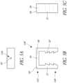
- FIG. 7Adepicts an embodiment of the invention of a device 20B that is similar to the device 20 and to the device 20A except as described differently below.
- the features of the device 20Bcan be combined or included with the device 20, 20A or any other embodiment discussed herein.
- the device 20Bcomprises a heart valve prosthesis.
- the device 20Bhas a locking clip 50B that fastens externally over the distal and proximal plates 22B, 24B.
- the distal and proximal guidewires 30B, 42Bpass through holes in the body of the locking clip 50B.
- the arms 51B of the locking clip 50Bcan extend over the periphery of the distal and proximal plates 22B, 24B.
- the arms 51B of the locking clip 50Bcan seat within the narrows 53a, 53b of the distal and proximal plates 22B, 24B.
- the locking clip 50Bcan be adapted so that the outer surface of the locking clip 50B is substantially flush with the outer surface of the distal and proximal plates 22B, 24B when the locking clip 50B is seated within the narrows 53a, 53b to secure the distal and proximal plates 22B, 24B together, thereby giving the device 20B a smooth outer surface.
- FIGS. 7B-7Dshow a top view, an end view, and a side view of the locking clip 50B depicted in FIG. 7A .
- the locking clip 50Bcan have a first hole 63B and a second hole 65B.
- the distal guidewire 30Bcan pass through the first hole 63B.
- the proximal guidewire 42Bcan pass through the second hole 65B.
- the locking clip 50Bcan be adapted to compress a tissue secured within the gap between the distal and proximal plates 22B, 24B by about: 1%, 5%, 10%, 20%, and values therebetween.
- the distal plate 22can be rotated about its attachment point to the distal guidewire 30 or suture, so that its long axis is parallel to the distal guidewire 30 or suture, and this assembly can be enclosed inside a delivery catheter.
- the proximal plate 24can be rotated about its attachment point to the proximal guidewire 42 or suture, so that its long axis is parallel to the proximal guidewire 42, also referred to as a traction wire 42 or suture, and this assembly is enclosed inside the same or a separate delivery catheter.
- a method of placement of the distal and proximal plates 22, 24 or the plates 22B, 24B within a single delivery catheteris provided below.
- this method of device placementis presented for illustrative purposes only and is not to be taken as limiting. Indeed the other heart valve prosthesis devices disclosed herein can be deployed in similar methods. The steps are not all required, nor must they be performed in the order presented.
- FIG. 8Adepicts an embodiment of a device 20C that is similar to the device 20 except as described differently below.
- the features of the device 20Ccan be combined or included with the device 20 or any other embodiment discussed herein.
- the device 20Ccan comprise a heart valve prosthesis.
- the device 20Ccomprises a connector 126 that is a locking pin 80C.
- the locking pin 80Ccan pass through a central opening in each of the distal and proximal plates 22C, 24C.
- the locking pin 80Ccan be coupled to a central guidewire 82C.
- the central guidewire 82Ccan be hollow, as discussed in more detail below.
- the central guidewire 82Ccan pass through central openings 81a, 81b (shown in FIG.
- the locking pin 80Ccan be configured to secure the distal plate 22C and the proximal plates 24C.
- the locking pin 80Ccan have a deformable feature with a cam surface that deflects toward the central guidewire 82C as the locking pin 80C is pulled through the proximal plate 24C. Once the deformable feature passes through the central opening 81b of the proximal plate 24C, the deformable feature may spring away from the central guidewire 82C, thereby preventing the locking pin 80C from moving distally relative to the proximal plate 22C.
- the locking pin 80Ccan be configured like a rivet.
- the locking pin 80Cis configured so that the locking pin 80C can collapse under compression, causing at least a portion of the locking pin 80C to expand radially outward.
- the radially-expanded portion of the collapsed locking pin 80Ccan be sized to prevent the locking pin 80C from passing back through the central opening 81b in the distal direction.
- the locking pin 80Cengages with one or both of the pates 22C, 24C in a manner similar to a push nut.
- An interference fitcan be provided between one or both of the locking pin 80C and the plates 22C, 24C.
- a reversible locking featuree.g., threaded nut
- the proximal end of the locking pin 80Ccan have an external thread (not shown) that mates with the internal thread of a threaded nut (not shown).
- a pusher cathetercan be used to advance the threaded nut along the central guidewire 82C.
- the threaded nutcan include an interlock feature (e.g., recess) that mates to a corresponding feature (e.g., protrusion) on the pusher catheter, thereby allowing the pusher catheter to advance the thread nut along the central guidewire 82C.
- the interlock featurecan be further adapted to allow the pusher catheter to rotate the threaded nut about the central guidewire 82C. In this way, the pusher catheter can be used to tighten or loosen the threaded nut onto the proximal end of the locking pin 80C.
- the distal and proximal plates 22C, 24Ccan have a recess 83a, 83b.
- the recess 83a, 83bis configured to interlock with the locking pin 80C.
- the recess 83a, 83bis configured to accommodate the guidewire 82C when the plate 22C, 24C is folded parallel to the guidewire 82C to avoid the guidewire 82C being forced to make a kink as the guidewire 82C passes through a central opening 81a, 81b of the plate 22C, 24C.
- FIG. 8Bshows an exploded view of the device 20C, illustrating that the locking pin 80C can have a shaft 84C and a collar 86C.
- the locking pin 80Ccan be sized so that the shaft 84C can pass through a central opening 81a in the distal plate 22C and through a central opening 81b in the proximal plate 24C.
- the collar 86Ccan be adapted so that the collar 86C cannot pass through the central opening 81a of the distal plate 22C.
- the collar 86C and the central opening 81aare both substantially axisymmetric.
- the collar 86C and the central opening 81acan be shaped so that the collar 86C can pass through the central opening 81a in some rotational configurations but cannot pass through the central opening 81a in other rotational configurations.
- the collar 86Ccould have a protrusion (not shown) that can pass through the distal plate 22C only when the protrusion is aligned with a slot (not shown) that extends from the central opening 81a.
- the distal and proximal plates 22C, 24Ccan be adapted to have a delivery configuration and a deployed configuration.
- the distal and proximal plates 22C, 24Ccan be made of a compliant material (e.g., polymer) that can be elastically deformed into a low-profile configuration (e.g., rolled up) and stored within a sheath that holds the plates 22C, 24C in the low-profile configuration for delivery through a catheter.
- the sheathcan be retracted to expose the plates 22C, 24C, thereby allowing the plates 22C, 24C to move to the deployed configuration (e.g., unroll).
- the distal and proximal plates 22C, 24Ccan comprise a shape memory material or super-elastic material (e.g., nitinol).
- the distal and proximal plates 22C, 24Ccan have a contoured shape that provides stabilization of the plate in fluid flow.
- the platecan be shaped so that the surface of the plate that is facing the valve leaflet aligns with a desired orientation (e.g., co-planar with the valve annulus) when blood is flowing past the plate.
- the desired orientation to utilize flow to help stabilize the plates 22C, 22Dis an inverted dome.
- the domed side (e.g., convex side) of the platefaces upstream, and the cupped side (e.g., concave side) faces downstream.
- the locking pin 80Ccan include an interlock feature 88C that mates with a corresponding feature on the distal plate 22C.
- the interlock feature 88Cis a notch that has a proximal-facing concave surface. The curvature of the notch matches a corresponding convex surface diposed on the distal-facing surface of the distal plate 22C.
- the interlock feature 88Ccan hold the distal plate 22C rotationally fixed relative to the locking pin 80C.
- the interlock feature 88Ccan allow adjustment of the position of the distal plate 22C.
- rotation of the locking pin 80Ccan cause the distal plate 22C to rotate with the locking pin 80C.
- the locking pin 80Ccan be rotated by rotating the central guidewire 82C.
- FIG. 8Cshows a bottom view of the distal plate 22C depicted in FIG. 8B .
- the distal-facing surface of the distal plate 22Chas a raised feature 90C that fits into the interlock 88C that is on the collar 86C of the pin 80C.
- rotation of the locking pin 80C about the longitudinal axis of the central guidewire 82Ccauses the distal plate 22C to rotate with the locking pin 80C about the longitudinal axis of the central guidewire 82C. In this way, the position of the distal plate 22C can be adjusted by manipulating the central guidewire 82C.
- FIG. 8Dshows a bottom view of the distal plate 22C alone, i.e., without the locking pin 80C.
- FIG. 9Adepicts an embodiment of a device 20D that is similar in some respects to the device 20C.
- the features of the device 20Ccan be combined or included with the device 20D.
- the device 20Dcan comprise a heart valve prosthesis.
- the device 20Dhas a locking pin 80D that passes through a central opening in each of the distal and proximal plates 22D, 24D.
- the distal plate 22Dincludes an eyelet 92D disposed on either end of the distal plate 22D.
- the eyelet 92Dis adapted to receive a barb 94D that is disposed on the proximal plate 24D.
- the barb 94Dcan be configured to pierce through a valve leaflet that is secured between the distal and proximal plates 22D, 24D.
- the barb 94Dcan have wing portions 96D that spring outward as the barb 94D is pushed through the eyelet 92D.
- the wing portions 96Dare configured to prevent the barb 94D from moving proximally back through the eyelet 92D after the wing portion 96D has passed distally through the eyelet 92D. In this way, the barb 94D and eyelet 92D can lock together the distal and proximal plates 22D, 24D. While not shown in FIG.
- the locking pin 80Dcan have a distal collar 86D that is similar to the distal collar 86D shown in FIG. 8C .
- the distal collar 86Dcan be configured to rotate the distal plate 22D and can be configured to pull the distal plate 22D toward the proximal plate 24D when tension is applied to the central guidewire 82D.
- the proximal plate 24Dcan be configured to have a flat configuration, as shown in FIG. 9B .
- the proximal plate 24Dis made of a shape memory material (e.g., nitinol sheet).
- the proximal plate 24Dcan fold flat for delivery. In some configurations, the proximal plate 24D bends from a flat configuration (shown in FIG. 9B ) to the bent configuration (shown in FIG. 9A ) upon the proximal plate 22D contacting a body fluid, or being released from a restrictive sheath, or increasing in temperature.
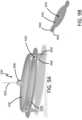
- FIG. 10Adepicts an embodiment of a device 20E that is similar to the devices 20, 20C, and 20D except as described differently below.
- the features of the device 20Ecan be combined or included with the devices 20, 20C, and 20D or any other embodiment discussed herein.
- the device 20Ecan comprise a heart valve prosthesis.
- the device 20Ehas a locking pin 80E that passes through a central opening in each of the distal and proximal plates 22E, 24E.
- the distal and proximal plates 22E, 24Ehave wings 100a, 100b that extend laterally away from a central ring 101a, 101b.
- the central rings 101a, 101bare examples of tubular bodies that are disposed generally in a central portion of the distal and proximal plates 22E, 24-E respectively.
- the wings 100a, 100bcan be configured to fold into a cylinder for deliver within a sheath of a delivery catheter.
- the wings 100a, 100bcan spring open so that the lateral portions of the wings 100a, 100b are further from the central guidewire 82E.
- FIG. 10Athe wings 100a, 100b are shown in the open or deployed configuration.
- the distal and proximal plates 22E, 24Ecan include an elastic or shape memory material that facilitates the distal and proximal plates 22E, 24E springing into the open configuration upon release of the distal and proximal plates 22E, 24E from a restricted state such as containment within a delivery sheath.
- the distal and proximal plates 22E, 24Eare fabricated from cut and formed nitinol tube.
- the distal and proximal plates 22E, 24Eare shaped to allow for easy retrieval of the plate back into the delivery sheath if the procedure is aborted.
- the proximal plate 24Ecan be recovered into the delivery sheath from the deployed configuration by advancing the delivery sheath distally over the proximal plate 24E to fold the wings 100b toward the central guidewire 82E.
- the distal plate 24Ecan be recovered into the delivery catheter by a lasso-like snare or by applying tension to a delivery suture that is temporary wrapped around the lateral portions of the wings 100a, thereby drawing the wings 100a toward the central guidewire 82E.
- the wings 100a, 100bhave a spring-like quality that allows the wings 100a, 100b to fold toward the longitudinal axis of the central guidewire 82E while the plates 22E, 24E are being withdrawn in the proximal direction.
- the distal and proximal plates 22E, 24Ecan include a grip feature 102E that helps secure the tissue (e.g., valve leaflet) between the distal and proximal plates 22E, 24E.
- the grip feature 102Eis a directional barb that points toward the central guidewire 82E and toward the opposing plate. The illustrated grip feature 102E facilitates "one-way" gripping of the leaflets, allowing the leaflets to only work themselves closer together with movement while preventing the leaflets from moving farther apart.
- FIG. 10Bis an exploded view of the device 20E depicted in FIG. 10A .
- the locking pin 80Ecan have an interlock 88E that mates with a corresponding feature on the distal plate 22E, as described above.
- the corresponding featureis a distal notch 89E disposed on the central ring 101a of the distal plate 22E.
- the distal notch 89Eis partially obscured by the wing 100a of the distal plate 22E.
- the distal notch 89Eis similar to the proximal notch 91E (shown in FIG. 10A ) that is disposed on the central ring 101b of the proximal plate 24E.
- tension applied to the central guidewire 82Ecan draw the locking pin 80E through the central rings 101a, 101b of the distal and proximal plates 22E, 24E.
- the interlock 88E on the collar 86E of the locking pin 80Ecan mate with the distal notch 89E to help rotate and position the distal plate 22E.
- the collar 86Ecan be sized so that the collar 86E cannot pass through the central ring 101a of the distal plate 22E in the proximal direction. Accordingly, tension applied to the central guidewire 82E will pull the distal plate 22E in the proximal direction.
- a pusher tube(not shown) can be advanced distally over the central guidewire 82E and can be used to push the proximal plate 24E toward the distal plate 22E.
- the pusher tubecan include an interlock that mates with the proximal notch 91E to allow the pusher tube to rotate and position the proximal plate 24E.
- the distal and proximal plates 22E, 24Eare compressed together by pulling the distal plate 22E toward the proximal plate 24E while simultaneously pushing the proximal plate 24E toward the distal plate 22E.
- the proximal notch 91Ecan receive an interference-fit locking nut 93 (shown in FIG.
- the locking nut 93is one example of a locking device. More generally in various embodiments a locking device can be provided that can provide a releasable coupling between teh compoentns of the device 20F can be employed.
- FIGS. 11A-Cshow illustrative attachment features that can allow a guidewire to be detached from the distal or proximal plates 22, 24.
- the distal end of the attachment feature 104can have an anchor feature 106 that mates with a receiving feature 105 (shown in FIG. 11C ) disposed on a portion of the distal plate 22-22F, on a portion of the proximal plate 24-24F, or on a portion of the locking pin 80C-F.
- the anchor feature 106can be a flexible wire that fits into a slot 107 on the distal or proximal plate 22, 24.
- the flexible wirecan be biased radially outward with sufficient force such that when the flexible wire is inserted into the slotted receiving region the flexible wire cannot be pulled out of the slot without applying a sufficiently high threshold level of force.
- the threshold level of force needed to pull the anchor feature 106 from the receiving regioncan be selected so that it is greater than the expected force that will be applied during delivery of the distal or proximal plate.
- the attachment feature 104can have an inflatable member 108 disposed within a cavity 110 at the distal end of the attachment feature 104.
- the inflatable member 108can be in fluid communication with an inflation lumen 112 that is disposed within the guidewire.
- FIG. 11Ashows the inflatable member 108 in the deflated state, in which the inflatable member is contained within the cavity 110.
- the inflatable member 108can be inflated by delivering an inflation fluid into the inflatable member 108 through the inflation lumen 112.
- FIG. 11Bwhen the inflatable member 108 is inflated, a portion of the inflatable member will extend beyond the cavity 110 and pry the anchor feature 106 from the distal or proximal plate 22, 24 (not shown), thereby disconnecting the guidewire from the distal or proximal plate 22, 24.
- FIGS. 12A-Cshow another embodiment of the attachment feature 104A.
- the attachment feature 104Acan include an inner elongate member 109 disposed within an outer member 111.
- the inner and outer elongate members 109, 111can be coaxial guidewires.
- the proximal ends of the inner and outer elongate members 109, 111can include a pin or other feature that locks the inner and outer elongate members 109, 111, thereby preventing the inner and outer elongate member 109, 111 from moving relative to one another.
- the attachment feature 104Acan include a locking element 113 that secures the inner and outer elongate members 109, 111 to the distal or proximal plate 22, 24.
- the locking elementis a ball 115 that passes through a hole of the outer elongate member 111 and sits within a recess 117 in the proximal plate 22.
- the end portion of the inner member 109is tiered. In the locked position, the end portion of the inner elongate member 109 holds the ball a first distance D1 from the proximal plate 22.
- the inner and outer elongate members 109, 111are first unlocked (e.g., removing a locking pin that passes through the proximal ends of the inner and outer elongate members 109, 111) to allow the inner and outer elongate members 109, 111 to move relative to one another.
- the inner elongate member 109is retracted proximally relative to the outer elongate member 111, as shown in FIG. 12B . This allows the ball 115 to drop out of the recess 1 17 so that the ball 115 is now a distance D2 away from the proximal plate 22.
- the outer elongate member 111can now be withdrawn from the proximal plate 22, as shown in FIG. 12C .
- the attachment feature 104Acan allow the inner and outer elongate members 109, 111 to be detached from the proximal plate 22.
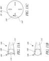
- FIGS. 13A-Cdepict another embodiment of the present disclosure that includes the use of a collapsible and expandable feature 60 such as a balloon or wire frame that can be passed to the ventricular side of the right ventricle in the collapsed state.
- FIG. 13Adepicts the expandable feature 60, in its unexpanded state, being advanced through superior vena cava, past the tricuspid valve 12, and into the right ventricle 16 of a heart 10 in normal diastole.
- FIG. 13Bdepicts the expandable feature 60 in its unexpanded state within the right ventricle of a heart in systole.
- FIG. 13Cdepicts the expandable feature 60 and expanded once in the right ventricle 16.
- this expandable feature 60can be such that the expandable feature 60 can snag or catch the leaflet edges when the tricuspid valve 12 is open but not pass between them.
- the tension of withdrawing the expanded expandable feature 60 from the right ventricle 12 into the right atrium 14therefore catches the leaflets of the tricuspid valve 12, forcing the leaflets closer together or into the closed position, thereby stabilizing them for fixation. In this way, the valve leaflets can be temporarily secured together.
- This devicewould allow the operator to pull back on the balloon in systole, and tent or force the leaflets into the closed position. The purpose of this is to evaluate any reduction in tricuspid regurgitation by fixing any coaptation line, or for temporarily holding two leaflets together while a permanent fixation device is affixed, as described below.
- the present disclosureincludes the use of a guidance rail to attain proper positioning within the tricuspid valve.
- a catheter or wireis threaded through the right atrium, through the tricuspid valve, through the right ventricle, into the right ventricular outflow tract, and into the main pulmonary artery.
- This catheter or wiremay be guided into position utilizing flow-directed guidance, echocardiography, ultrasonography, fluoroscopy, a steerable catheter, or some combination thereof.
- a fixation device for the tricuspid valvecan then be threaded over this guidance rail and to the level of the tricuspid valve.
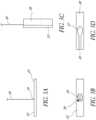
- FIG. 14depicts another embodiment of the present disclosure that includes the use of a guidance rail.
- the guidance rail 60can be advanced through the right atrium 14, past the tricuspid valve 12, and embedded into the right ventricle 16.
- a catheter or wire with a penetrating threaded tip 62can be advanced via a delivery catheter into the right ventricle.
- the threaded tip 62may be configured to bore into the interventricular septum or some other portion of the right ventricle such that the catheter or wire can be made taut under tension.
- Positioning and guidancecan be provided utilizing echocardiography, ultrasonography, fluoroscopy, or some combination. The delivery catheter can then be removed.
- a fixation device for the tricuspid valve 12can then be threaded over the guidance rail 60 and to the level of the tricuspid valve 12.
- the guidance rail 60can be removed either in its entirety, or leaving the penetrating threaded tip 62 in situ and removing only the catheter or wire portion.
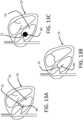
- FIG. 15depicts another embodiment of the present disclosure that includes the use of a guidance rail.
- a removable guidance rail 60'may be advanced through the right atrium 14, past the tricuspid valve 12, and secured against a wall of the right ventricle 16.
- the removable guidance rail 60'may be secured using suction.
- a catheter or wire with a deployable, high compliance, and large area suction tip 64can be advanced into the right ventricle 16 via a delivery catheter.
- the suction tip 64can be positioned against a ventricular wall surface and suction can be applied, holding the suction tip 64 firmly against some portion of the right ventricle 16 such that the catheter or wire can be made taut under tension.
- Positioning and guidancecan be provided utilizing echocardiography, ultrasonography, fluoroscopy, or some combination.
- the delivery cathetercan then be removed.
- a fixation device for the tricuspid valve 12can then be threaded over this guidance rail 60' and delivered to the level of the tricuspid valve 12.
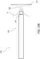
- FIG. 16depicts an embodiment of the present disclosure that includes a threaded tip 62.
- a delivery catheter 70may be used to guide and deliver the threaded tip 62 into the right ventricle.
- the threaded tip 62can have a penetrating tip. Torque can be transmitted through the delivery catheter 70 or through a wire 72 connected to the threaded tip 62.
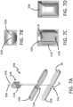
- FIGS. 17A and 17Bdepict another embodiment of the present disclosure that includes a suction tip 64.
- the suction tip 64can be a high area, high compliance skirt.
- the suction tip 64can be stowed within the delivery catheter 70.
- FIG. 17Adepicts the suction tip 64 partially unfurled from its stowed configuration.
- FIG. 17Bdepicts the suction tip 64 in its fully deployed configuration. When unfurled, the suction tip can form a skirt that can be applied to a ventricular surface. Suction can be applied to secure the suction tip 64 to the ventricular wall.
- the suction tip 64may be coupled to a guidewire 73.
- the guidewire 73may contain a lumen that allows suction to be applied to the distal face 74 of the suction tip 64. Suction can be provided by external aspiration.
- FIG 18depicts an embodiment of a device 20F that is similar to the devices 20 and 20C-20E except as described differently below.
- the features of the device 20Fcan be combined or included with the devices 20 and 20C-20E or any other embodiment discussed herein.
- the device 20Fcan comprise a heart valve prosthesis.
- the device 20Fhas a locking pin 80F and configured to be deployed over a guidance rail 60F.
- the central guidewire 82Fcan be hollow and can concentrically surround the guidance rail 60F that is connected to the threaded tip 62F.
- the locking pin 80Fcan be connected to the central guidewire 82F using a detachable attachment feature 104 described above.
- the distal face of the locking pin 80Fcan have an opening 87F (shown in FIG.
- the device 20Fcan be preassembled by passing the proximal end of the rail 60F through the opening 87F and into the rail lumen of the hollow central guidewire 82F.
- the rail 60Fcan be sufficiently sized to pass out the proximal end of the hollow central guidewire 82F.
- the hollow central guidewire 82Fmay also include an inflation lumen for detaching the detachable attachment feature 104, as described above.
- the guidance rail 60Fcan first be advanced and anchored in the right ventricle.
- the locking pin 80F and hollow central guidewire 82F that were pre-assembled onto the guidance rail 60Fcan then be advanced along the anchored rail 60F.
- the distal plate 22Fcan then be advanced over the hollow central guidewire 82F and positioned using the collar 86F on the locking pin 80F.
- the proximal plate 24Fcan then be advanced over the central guidewire 82F.
- a pusher tube inserted over the central guidewire 82Fcan be used to advance and position the proximal plate 24F, as described above.
- the distal and proximal plates 22F, 24Fcan then be secured together by the locking pin 80F.
- the central guidewire 82Fcan then be detached from the distal and proximal plates 22F, 24F by inflating the member 1 06 of the detachable attachment feature 104.
- FIG. 19depicts a top view of a tricuspid valve 12, illustrating that the present disclosure envisions variable placement of the device 20 or any of the other devices 20A-20F, as denoted by the dashed lines indicating potential locations L of the device 20. Positioning of the device 20-20F is variable depending on the location of tricuspid regurgitation. For the majority of cases, an attempt may be made to "bicuspidize" the tricuspid valve by deploying one or more devices 20-20F along any single coaptation line, such that two leaflets are now attached and function as a single large leaflet. In some methods, echocardiography and fluoroscopy are used in conjunction with a steerable tip delivery catheter to achieve device positioning that best limits regurgitation. A device can then be deployed at that location and valve regurgitation can be re-evaluated. If needed, additional devices may be deployed to further reduce valve regurgitation.
- FIGS 19A-19Gillustrate a variety of delivery systems and methods that can be combined with the devices 20-20F.
- the delivery systemscan be employed in methods to place the devices 20-20F as discussed above.
- Figure 19Ashows placing a guidewire 200 along the venous vasculature V into the heart H.
- the guidewire 200can be a flow directed guidewire or can be delivered using other techniques.
- Figure 19Bshows that a delivery system 204 is advanced over the guidewire 200 until a distal portion 208 of the delivery system 204 is disposed adjacent to the heart H. The proximal portion of the delivery system 204 is not shown but would be outside the patient at a peripheral access site.
- the delivery system 204includes a catheter that is configured to deliver some or all of the components of any of the devices 20-20F therein in an unassembled state. In other approaches, separate catheters can be used to deliver individual components of the device 20-20F.
- Figure 19Cshows that further advancement of the delivery system 204 places the distal end 208 in the heart H, in particular at or across the tricuspid valve TV. Thereafter, the components of the device 20-20F can be deployed individually.
- Figure 19C-1shows details of the internal arrangement within the distal end 208 of the delivery system 204.
- the device 20Bis disposed in the distal end 208 in an unassembled state.
- the distal plate 22Bwhich is one form of a distal member or a first member, is disposed in a first segment 220 of the distal portion 208.
- the first segment 220can be a distal-most segment that extends from a distal tip 221 of the distal portion 208 proximally to a location proximal of the distal plate 22B.
- the proximal plate 24Bwhich is one form of a proximal member or a second member, is disposed in a second segment 222 of the distal portion 208.
- the second segment 222is disposed immediately proximal of the first segment 220.
- the proximal plate 24Bis disposed between the distal plate 22B and a proximal end of the delivery system 204.
- the distal plate 22B and the proximal plate 24Bare aligned end-to-end in the distal end 208 of the delivery catheter 204. Ends of the plates 22B, 24B that oppose each other are spaced apart along the length of the distal portion 208.
- the locking clip 50Bis an example of a connector that connects the plates 22B, 24B by being advanced from a proximal side of the proximal plate 24B over the proximal plate 24B, then over a proximal side of the distal plate 22B until it engages the distal plate 22B as discussed above.
- the locking clip 50Bis disposed in a third segment 224 of the distal portion 208 that is disposed immediately proximal of the second segment 222.
- a pusher member 230which can be a pusher catheter, can be disposed in a lumen of the delivery catheter 204.
- the pusher member 230can act on any one or more of the distal plate 22B, 24B, or clip 50B to move these components out of the delivery catheter 204 into the heart.
- Figure 19C-2shows another embodiment of a delivery system 234 that can be similar to the system 204 except as described differently below.
- the delivery system 234has first, second and third segments 220, 222, 224.
- the locking pin 80Cwhich is another form of a connector as disclosed herein, can be disposed in the first segment 220.
- the locking pin 80Cis an example of a connector as disclosed herein that is advanced into the heart first and thereafter is a base onto which distal and proximal plates 22C, 24C are mounted.
- the distal plate 22Cis disposed in the second segment 222 and the proximal plate 24C is disposed in the third segment 224.
- a fourth segmentcan include a space configured to house a locking nut or other locking device that can be used to secure the distal and proximal plates 22C, 24C.
- Figures 19D-19Gillustrate the use of the delivery system 234 to build the device 20C within the heart.
- the locking pin 80Cwhich is a form of a connector, is advanced out of the distal tip 221 of the distal portion 208.
- Figure 19Dshow that the locking pin 80C can be advanced across leaflets of the valve TV. Such movement can be by floating the pin 80C or by pushing it using the pusher member 230. Such movement can result from holding the pin 80C stationary in the right ventricle and withdrawing the distal tip 221.
- Figure 19Eshows that thereafter the distal plate 22C can be advanced over the proximal end of the locking pin 80C. The advancement of the distal plate 22C can be achieved by then pusher member 230 which can thereafter be withdrawn back into the distal portion 208.
- the proximal plate 24Ccan be advanced out of the distal portion 208, for example using the pusher member 230. As the proximal plate 24C is advanced over the pin 80C the leaflets of the tricuspid valve TV are brought together and trapped. The proximal plate 24C can be secured to the pin 80C by an interference fit between the proximal plate 24C and the pin 80C. In addition, or in the alternative, a locking nut as discussed above in connection with Figure 18 can be advanced over the proximal portion of the locking pin 80C to removeably or releasably secure the proximal plate 24C to the locking pin 80C.
- Figure 19Gshows the leaflet of the tricuspid valve TV secured in a space between a proximal surface of the distal plate 22C and a distal surface of the proximal plate 24C.
- the leaflet thickness of the tricuspid valve TVis much greater in Figure 19G illustrating that the space between the plates 22C, 24C can be such that the leaflets fit in the space but are securely trapped, such as by at least some compression of the leaflets.
- Another aspect of the present disclosuremay include the use of a grasper that relies on suction to securely hold each leaflet in position for repair.
- This graspercan include a series of orifices that are connected to an externally actuated source of vacuum, such that a leaflet positioned in proximity to the orifices will be sucked against the orifices, reducing leaflet movement.
- Another aspect of the present disclosuremay achieve fixation of the leaflet edges by securing the individual leaflet coaptation edges first, then fixing the edges of two adjacent edges together.
- Thiscan be performed by any securing method such as by applying a suture or staple with or without a pledget to each leaflet coaptation edge, then securing the two sutures or staples together.
- This methodmay require the operator to secure only one leaflet edge at a time, rather than two edges simultaneously.
- the present methodsmay include affixing a winged feature to each leaflet edge individually, then securing the features together and thereby securing the leaflet edges together.
- the present disclosurealso includes the technique of externalizing sutures that may be applied to the leaflet edges itself, or to a winged feature which is affixed to the leaflet edges, externalizing these sutures, and tying and passing the suture knot intravascularly to the tricuspid valve.
- Another embodiment of this deviceachieves fixation by securing two adjacent leaflet edges by tension, clamp, or suction, and applying a fixation device such as a suture or staple, with or without a pledget, to the two adjacent leaflet edges, thereby securing them together.
- a fixation devicesuch as a suture or staple, with or without a pledget
Landscapes
- Health & Medical Sciences (AREA)
- Cardiology (AREA)
- Life Sciences & Earth Sciences (AREA)
- Engineering & Computer Science (AREA)
- General Health & Medical Sciences (AREA)
- Biomedical Technology (AREA)
- Heart & Thoracic Surgery (AREA)
- Veterinary Medicine (AREA)
- Public Health (AREA)
- Animal Behavior & Ethology (AREA)
- Vascular Medicine (AREA)
- Oral & Maxillofacial Surgery (AREA)
- Transplantation (AREA)
- Surgery (AREA)
- Nuclear Medicine, Radiotherapy & Molecular Imaging (AREA)
- Medical Informatics (AREA)
- Molecular Biology (AREA)
- Reproductive Health (AREA)
- Prostheses (AREA)
Description
- The present disclosure relates to devices and methods for treating regurgitation in a heart valve.
- The tricuspid valve separates the right lower heart chamber (the right ventricle) from the right upper heart chamber (right atrium). Tricuspid regurgitation is a disorder in which this valve does not close tight enough. This problem causes blood to flow backward into the right upper heart chamber (atrium) when the right lower heart chamber (ventricle) contracts. Tricuspid regurgitation is leakage of blood backwards through the tricuspid valve each time the right ventricle contracts. Tricuspid regurgitation usually results from an enlarged lower heart chamber (called the ventricle) or from any other condition that constrains the blood flow from the right ventricle to the lungs. Sometimes long-standing disorders, such as emphysema or pulmonary stenosis can cause problems that affect the tricuspid valve which is "upstream" from the lungs. To compensate, the right ventricle enlarges so that it can pump harder, which sometimes causes the tricuspid opening to become stretched out and floppy. When valve disease is severe, it may be necessary to repair or replace the diseased valve. Valve repair is the most common surgical treatment for tricuspid valve disease. Tricuspid valve repair can be done alone or in combination with treatments for other heart problems.
- Tricuspid valve repair using an annuloplasty ring is a common surgical approach for tricuspid regurgitation and may be performed for primary tricuspid disease or for combined cases with other valve surgery (mitral, aortic). Traditional tricuspid valve repair is an open-heart procedure performed through a 152 - 203mm (6 - 8 inch) incision through the breastbone (sternum).
- For these reasons, there exists a need for minimally invasive methods of tricuspid valve repair. The present disclosure is directed to valve fixation devices that can be delivered endovascularly.
WO02/034167
According to the present invention, such a prosthesis is characterised by the characterising features of claim 1. - A more complete appreciation of the subject matter of this application and the various advantages thereof can be realized by reference to the following detailed description, in which reference is made to the accompanying drawings, wherein embodiments of the invention are depicted in
figures 2 ,5A-7D , and in which: FIG. 1A depicts a cross-sectional view of a heart in normal diastole.FIG. 1B depicts a cross-sectional view of a heart in normal systole.FIG. 2 depicts a side view of an embodiment of a fixation device.FIG. 3A shows a side view of an embodiment of a distal plate.FIG. 3B shows a top view of an embodiment of a distal plate in a low-profile configuration.FIG. 3C is a side view of the embodiment depicted inFIG. 3A , with an addition of a pledget intended to contact the tricuspid valve.FIG. 3D is a top view of an embodiment of a pledget.FIG. 4A is a side view of a proximal plate.FIG. 4B is a bottom view of a proximal plate.FIG. 4C is an end view of a proximal plate.FIG. 4D is a side view of the embodiment of the proximal plate depicted inFIG. 4A , with the proximal plate being actuated to a low profile configuration.FIG. 5A is a top view of an embodiment of a locking clip.FIG. 5B is an end view of an embodiment of a locking clip.FIG. 5C is a side view of an embodiment of a locking clip.FIG. 6A is an isometric view of an embodiment of a fixation device.FIG. 6B is a top view of an embodiment of a locking clip.FIG. 6C is an end view of an embodiment of a locking clip.FIG. 6D is a side view of an embodiment of a locking clip.FIG. 6E is an isometric view of the fixation device ofFIG 6A .FIG. 6F is a partial bottom view of the proximal plate of the fixation device ofFIG. 6A .FIG. 7A is an isometric view of an embodiment of a fixation device.FIG. 7B is a top view of an embodiment of a locking clip.FIG. 7C is an end view of an embodiment of a locking clip.FIG. 7D is a side view of an embodiment of a locking clip.FIG. 8A is an isometric view of an embodiment of a fixation device included for background interest only.FIG. 8B is an exploded view of the fixation device ofFIG. 8A .FIG. 8C is a bottom view of a portion of the fixation device ofFIG. 8A .FIG. 8D is a bottom view of the distal plate ofFIG. 8A .FIG. 9A is an isometric view of an embodiment of a fixation device included for background interest only.FIG. 9B is an isometric view of the proximal plate ofFIG. 9A in a low-profile configuration.FIG. 10A is an isometric view of an embodiment of a fixation device included for background interest only.FIG. 10B is an exploded view of the fixation device ofFIG. 10A .FIG. 11A is a side view of a guidewire detachment feature in the uninflated state.FIG. 11B is a side view of the guidewire detachment feature of 11A in the inflated state.FIG. 11C is a top view of a portion of a plate or pin that has an attachment feature.FIG. 12A is a side view of a guidewire detachment feature in the secured state.FIG. 12B is a side view of the guidewire detachment feature of 12A in the released state.FIG. 12C is a side view of the guidewire detachment feature of 12A in the detached state.FIG. 13A is a cross-sectional view of a heart with an embodiment of an expandable fixation device. The expandable fixation device is in its unexpanded state and the heart is in diastole.FIG. 13B depicts the embodiment ofFIG. 6A with the heart in systole.FIG. 13C is the embodiment ofFIG. 6A with the expandable fixation device in its expanded configuration.FIG. 14 is an embodiment of a fixation device having a guidance rail embedded into the ventricular wall.FIG. 15 is an embodiment of a fixation device having a suction tip.FIG. 16 is an embodiment of a threaded tip for embedding into the ventricular wall.FIG. 17A is an isometric view of an embodiment of a suction tip in its partially deployed configuration.FIG. 17B is an isometric view of the embodiment ofFIG. 10A in its fully deployed configuration.FIG. 18 is an isometric view of an embodiment of a fixation device deployed over a guidance rail included for background interest only.FIG. 19 is a top view of a tricuspid valve illustrating a non-limiting selection of locations for placement of the device across the valve leaflets.FIG. 19A is a cross-sectional view of a heart showing placing a guidewire along the venous vasculature into the heart.FIG. 19B is a cross-sectional view of a heart showing advancing a delivery system along a guidewire into the heart.FIG. 19C is a cross-sectional view of a heart showing a delivery system in the vicinity of a heart valve.FIG. 19C-1 is a cross-sectional view of a delivery system showing the internal arrangement of the device components within the distal end of the delivery system.FIG. 19C-2 is a cross-sectional view of a delivery system showing the internal arrangement of the device components within the distal end of the delivery system included for background interest only.FIG. 19D shows a pin being deployed from a delivery device included for background interest only.FIG. 19E shows a distal plate being deployed from a delivery device included for background interest only.FIG. 19F shows a proximal plate being deployed from a delivery device included for background interest only.FIG. 19G shows a device deployed on a heart valve included for background interest only.- More detailed descriptions of various embodiments of catheter based transapical delivery systems, components and methods useful to treat patients are set forth below.
- This device represents an endovascular method of reducing tricuspid regurgitation in patients with severe tricuspid regurgitation. This device is intended to be delivered preferably through the right internal jugular vein due to anatomical considerations, but may also be delivered through the left internal jugular vein or via the inferior vena cava.
- The working principle of this device is the reduction of tricuspid regurgitation through the fixation of tricuspid valve leaflet edges.
FIG. 1A is a schematic representation of aheart 10 in normal diastole.FIG. 1B represents theheart 10 in normal systole. Theheart 10 consists of four chambers and thetricuspid valve 12 is interposed between theright atrium 14 and theright ventricle 16. - The present disclosure may represent a single point fixation between two leaflet edges of either two or three leaflets, or complete edge to edge fixation of the coaptation edges of two or three leaflets, or some combination of these methods. The right internal jugular vein (not shown) is preferable for delivery due to its most direct placement above the
tricuspid valve 12. However, the devices and methods herein disclosed may be delivered through the left internal jugular vein or the inferior vena cava. - Some aspects of the present disclosure encompass a method of delivering to the ventricular side of the
tricuspid valve 12, and steering with a steerable catheter to the desired leaflet coaptation point, an anchor that can include an attached and externalized guidewire or suture that is configured to secure the coaptation edge of two tricuspid leaflets at the ventricular surface. The externalized guidewire or suture can possess sufficient torsional rigidity to allow rotational control of the distal anchor. Tension can then be applied through the attached guidewire or suture to the distal anchor in the ventricular to atrial direction so that the coaptation edge of the two leaflets of interest may be brought closer together or, in some cases, forced closed. A means of then securing the leaflet coaptation edges can then be employed to cause the two edges to become fixed together. This procedure can then be repeated as needed to reduce the amount of tricuspid regurgitation. FIG. 2 depicts a non-limiting exemplary embodiment of a device according to the invention. In various embodiments herein, thedevice 20 and variations discussed below comprise a heart valve prosthesis. Thedevice 20 includes two rigid or semi-rigid plates, referred to as thedistal plate 22 and theproximal plate 24. In some aspects, the distal andproximal plates proximal plates central portion 128 and aperipheral portion 130. In some configurations, the tricuspid leaflet edges are held between theperipheral portions 130 of the distal andproximal plates central portion 128 of theplates FIG. 5B ). Theconnector 126 can be disposed across a gap between the distal andproximal plates proximal plates FIGS. 5A-C ), thereby forming a durable fixation device. The distal andproximal plates FIGS. 3A and 3B depict a side view and a top view of a non-limiting exemplary embodiment of adistal plate 22. Thedistal plate 22 can be a rectangular plate comprised of metal (e.g., stainless steel, titanium, or titanium-containing alloy) or polymer. Thedistal plate 22 may incorporateslots 26 that facilitate alignment and fixation with theproximal plate 24. Adistal guidewire 30 or suture that is externalized from the patient may be attached to thedistal plate 22 to allow traction to be applied to thedistal plate 22. Thedistal guidewire 30 can be configured to provide rotational control of thedistal plate 22. Thedistal plate 22 may or may not include a compliant material layer (not shown) bonded to thesurface 32 of thedistal plate 22 at the point of contact with the tricuspid leaflets. Thedistal guidewire 30 or suture can be mounted slightly off center along the long axis of thedistal plate 22 on a pivotinganchor 34, which can allow thedistal plate 22 to be rotated such that its long axis is parallel to thedistal guidewire 30 or suture.FIG. 3C shows a side view of thedistal plate 22 rotated such that its long axis is parallel to thedistal guidewire 30. In some aspects, thedistal plate 22 may interface with apledget 38. A non-limiting exemplary embodiment of apledget 38 is shown inFIG. 3C and is discussed below. Thedistal plate 22 may provide a sturdy mechanical backing for thepledget 38.FIG. 3D depicts a top view of a non-limiting exemplary embodiment of apledget 38. Thepledget 38 can be made of woven or non-woven fibrous material such as Dacron or Gore-Tex or a bulk material such as silicone rubber. Thepledget 38 can include anotch 39 cut into the material to allow thedistal guidewire 30 to fold flat against thedistal plate 22 as shown inFIG. 3C . Thepledget 38 can be configured to enhance securement of the tricuspid valve between the distal andproximal plates pledget 38 may act as a cushion. Thepledget 38 may receive spikes on theproximal plate 24 that pass through the valve leaflet and penetrate thepledget 38 as theproximal plate 24 is pushed toward thedistal plate 22. In some configurations, the locking clip passes through a circular cut-out 37 of thepledget 38. The locking clip clips completely outside the perimeter of the plates in one embodiment. Some embodiments incorporate a clip that penetrates thepledget 38.FIGS. 4A-C depict a side view, a bottom view, and an end view of a non-limiting exemplary embodiment of aproximal plate 24. Theproximal plate 24 can be a rectangular plate comprised of metal or polymer. Theproximal plate 24 may incorporate a protruding feature (not shown) that mates and self-aligns with thedistal plate 22. Theproximal plate 24 may includeslots 36 that align with theslots 26 of thedistal plate 22, thereby facilitating the passage of a barbed locking clip to fix the distal andproximal plates proximal plate 24 can include a feature 40 (e.g., through hole) to allow passage of thedistal guidewire 30 or suture from thedistal plate 22. Theproximal plate 24 may have an affixedproximal guidewire 42 or suture that is externalized from the patient to allow traction and rotational control to be applied to theproximal plate 24. Theproximal guidewire 42 or suture can be mounted centrally on theproximal plate 22 on a pivotinganchor 44. The pivotinganchor 44 may be configured to allow theproximal plate 24 to be rotated such that its long axis is parallel to theproximal guidewire 42 or suture, as shown inFIG. 4D . A friction enhancing feature such as a series of teeth, bumps, or surface roughening may or may not be applied to the surface of the distal orproximal plate proximal plate 24 can include one ormore grooves 43 a,b. Thegrooves 43 a,b can extend more than halfway across thedistal plate 24 and overlap with one another so that when theproximal plate 24 and itsguidewire 42 are in the deployed configuration (i.e., long axis of theproximal plate 24 is perpendicular to the proximal guidewire 42), there exists ahole 40 through which the proximal end of thedistal guidewire 30 can be threaded. When theproximal plate 24 is in the folded configuration (i.e., long axis of theproximal plate 24 is parallel to its guidewire 42), thegrooves 43 a,b can allow thedistal guidewire 30 to clear the ends of theproximal plate 24. When theproximal plate 24 is viewed end-on, the overlappinggrooves 43 a,b can form a through hole that allows theproximal plate 24 to be advanced lengthwise over thedistal guidewire 30, through a catheter, to the right atrium where theproximal plate 24 can be rotated 90 degrees relative to theproximal guidewire 42 to bring theproximal plate 24 into the deployed configuration. The slot configuration allows thedistal guidewire 30 to clear theproximal plate 24 so that it now passes only through thehole 40.FIGS. 5A-C depict a top view, an end view, and a side view of a non-limiting exemplary embodiment of aconnector 126. Theconnector 126 is a lockingclip 50. The lockingclip 50 can be a rigid part made of metal or polymer. The lockingclip 50 includes anopen end 120 and aclosed end 122. As described below, theopen end 120 can be advanced initially over theproximal plate 24 and subsequently over thedistal plate 22. The locking clip may include spaced apartarms 51 that extend from abridge portion 56. Thearms 51 can include raisedfeatures 52 that can be threaded through theconcentric slots proximal plates arms 51 can be pushed over the edges of the distal andproximal plates connector 126 includes anaperture 124 configured to receive a guidewire. The lockingclip 50 can include acentral hole 54 to allow passage of the distal andproximal guidewires proximal plates clip 50 through the distal andproximal plates bridge portion 56 prevents the lockingclip 50 from passing through theconcentric slots proximal plates bridge portion 56 of the lockingclip 50 may also integrate a compliant material where the lockingclip 50 contacts theproximal plate 24. The compliant material can act as a spring to push theproximal plate 24 against thedistal plate 22. In some aspects of the present disclosure, when the barbed ends of the raised features 52 are threaded through theconcentric slots distal plate 22, thereby causing thebridge portion 56 to apply a retaining force against the atrial side of theproximal plate 22, the effect of which is similar to a rivet holding the distal andproximal plates clip 50 can be a U-shaped part featuring barbed ends that fasten externally over the distal andproximal plates FIG. 6A depicts an embodiment of the invention of adevice 20A that is similar to thedevice 20 except as described differently below. The features of thedevice 20A can be combined or included with thedevice 20 or any other embodiment discussed herein. Thedevice 20A comprises a heart valve prosthesis. Thedevice 20A has alocking clip 50A that fastens externally to the periphery of the distal andproximal plates proximal plates narrows proximal plates narrows FIG. 6A . Thelocking clip 50A can be advanced along thedistal guidewire 30A so that thearms 51A of thelocking clip 50A extend through thenarrows proximal plates distal guidewire 30A passes through acentral hole 54A of thelocking clip 50A, and theproximal guidewire 42A does not pass through thelocking clip 50A. In some embodiments, theproximal guidewire 42A is disposed laterally outward of anend surface 57A of thenarrows 53b. In other words, theend surface 57A of thenarrows 53b of theproximal clip 24A can be disposed between theproximal guidewire 42A and aface 59A of thelocking clip 50A. As discussed, the distal andproximal plates pledget 38A. The illustrated embodiment shows that thepledget 38A can be substantially uniform across the face of the plate and need not have a groove 39 (shown inFIG. 3D ).- The
locking clip 50A can have a thickness dimension that is oriented normal to theface 59A. In other words,FIG. 6A shows thelocking clip 50A oriented so that the thickness dimension of thelocking clip 50A is aligned parallel with the longitudinal axis of the distal andproximal plates proximal guidewire 42A outside of thelocking clip 50A, the thickness of thelocking clip 50A can be reduced. Reducing the thickness of thelocking clip 50A can reduce backflow through the anchor point (e.g., thenarrows locking clip 50A is secured to the valve leaflets. Thelocking clip 50A can have a width dimension that is oriented along a line that extends between thearms 51A of thelocking clip 50A. The width of thelocking clip 50A can be selected so that the side face 63A is substantially flush with the lateral portions of the distal andproximal plates locking clip 50A is seated within thenarrows locking clip 50A can be adapted so that the outer surface of thelocking clip 50A is substantially flush with the outer surface of the distal andproximal plates locking clip 50A is seated within thenarrows proximal plates device 20A a smooth outer surface. The edges of thedevice 20A can be contoured to be smooth and rounded. In some configurations, the edges of the device are contoured (e.g., rounded) to avoid thrombosis. FIGS. 6B-6D show a top view, an end view, and a side view of thelocking clip 50A depicted inFIG. 6A . Thelocking clip 50A can be laser cut from flat sheet material for ease of manufacturing. As described above, thearms 51A of thelocking clip 50A can have a raisedfeature 52A that engages with the edge of thedistal plate 22A. In the illustrated embodiment, thelocking clip 50A has a raisedfeature 52A with a cam surface adapted to allow the raisedfeature 52A to be advanced distally over aridge 55A within thenarrows 53a of thedistal plate 22A. The cam surface of the raisedfeature 52A cause thearms 51A of thelocking clip 50A to deflect laterally away from the center line of thelocking clip 50A as thelocking clip 50A is advanced distally over theridge 55A. Once the cam surface of the raisedfeature 52A clears theridge 55A, thearms 51A of thelocking clip 50A spring back toward the center line of thelocking clip 50A, thereby securing theridge 55A of thedistal plate 22A behind a flat proximally-facing surface of the raisedfeature 52A and restricting movement of thelocking clip 50A in the proximal direction. Thelocking clip 50A can be sized so that when the raisedfeature 52A is seated over theridge 55A of thedistal plate 22A, the undersurface 61A of thebridge portion 56A compresses theproximal plate 24A toward thedistal plate 22A. Thelocking clip 50A can be sized to compress a tissue (e.g., tricuspid valve leaflet) secured within the gap between the distal andproximal plates locking clip 50A can be adapted to compress a tissue by about: 1%, 5%, 10%, 20%, and values therebetween. A compression of about 10% means that the thickness of the uncompressed tissue is 10% greater than the thickness of the compressed tissue.FIG. 6E shows an isometric view of the other end of thedevice 20A.FIG. 6F shows a bottom view of theproximal plate 24A. As discussed above, theproximal plate 24A can have agroove 43b' on the leaflet-facing surface of theproximal plate 24A. Thegroove 43b' can accommodate thedistal guidewire 30A when theproximal plate 24A is in the low-profile configuration. As shown inFIG. 6F , thepledget 38A can have a groove 39' that aligns with thegroove 43b' of theproximal plate 24A.FIG. 7A depicts an embodiment of the invention of adevice 20B that is similar to thedevice 20 and to thedevice 20A except as described differently below. The features of thedevice 20B can be combined or included with thedevice device 20B comprises a heart valve prosthesis. Thedevice 20B has alocking clip 50B that fastens externally over the distal andproximal plates proximal guidewires locking clip 50B. As described above, thearms 51B of thelocking clip 50B can extend over the periphery of the distal andproximal plates arms 51B of thelocking clip 50B can seat within thenarrows proximal plates locking clip 50B can be adapted so that the outer surface of thelocking clip 50B is substantially flush with the outer surface of the distal andproximal plates locking clip 50B is seated within thenarrows proximal plates device 20B a smooth outer surface.FIGS. 7B-7D show a top view, an end view, and a side view of thelocking clip 50B depicted inFIG. 7A . As shown inFIG. 7B , thelocking clip 50B can have afirst hole 63B and asecond hole 65B. Thedistal guidewire 30B can pass through thefirst hole 63B. Theproximal guidewire 42B can pass through thesecond hole 65B. As described above, thelocking clip 50B can be adapted to compress a tissue secured within the gap between the distal andproximal plates - In pre-delivery configuration, the
distal plate 22 can be rotated about its attachment point to thedistal guidewire 30 or suture, so that its long axis is parallel to thedistal guidewire 30 or suture, and this assembly can be enclosed inside a delivery catheter. Likewise, theproximal plate 24 can be rotated about its attachment point to theproximal guidewire 42 or suture, so that its long axis is parallel to theproximal guidewire 42, also referred to as atraction wire 42 or suture, and this assembly is enclosed inside the same or a separate delivery catheter. - A method of placement of the distal and
proximal plates plates - 1. Place right internal jugular vein access sheath
- 2. Through this sheath, advance and steer the distal delivery catheter tip to just distal to the tricuspid valve.
- 3. Advance the distal plate, such as the
plate 22B or any of the other distal plates beyond adelivery catheter 208 as shown inFigure 19C-1 using the attachedtraction wire 30A. - 4. Under fluoroscopic/echocardiographic guidance, position the
distal plate 22B or any of the other distal plates parallel to the tricuspid valve plane coaptation line (perpendicular to itstension wire 30B). - 5. Withdraw and park the tip of the
delivery catheter 208 into the right atrium. - 6. Adjust manual tension on the
distal wire 30B, allowing thedistal plate 22B to tent the tricuspid valve closed, and evaluate tricuspid regurgitation. - 7. Advance the
proximal plate 24B or any of the other proximal plates disclosed herein beyonddelivery catheter 208 using the attachedtension wire 42B - 8. Apply manual tension on the
proximal plate wire 42B so thatproximal plate 24B is pulled back firmly against itsdelivery catheter 208, and positioned parallel to the plane of the tricuspid valve and coaptation line (perpendicular to itstension wire 42B). - 9. Holding the
proximal plate 24B against thedelivery catheter 208, advance thedelivery catheter 208 with proximal plate over thedistal plate wire 30B. In the case of the embodiment ofFIGS. 2-5C , if alignment features are present one can cause the raised proximal plate alignment features to mate with the distal plate slots. - 10. Simultaneously pull on the distal
plate tension wire 30B and push on thedelivery catheter 208 to force the twoplates - 11. Withdraw the delivery catheter, leaving the two tension wires in place. In one embodiment where the proximal plate has teeth that penetrate through the tricuspid valve and into a pledget backing material that is secured to the distal plate, the force of the pledget material on the proximal plate teeth can hold the leaflets together. In one embodiment, the distal plate, proximal plate, and locking clip are all enclosed in a single delivery catheter, once the proximal and distal plates are forced together, the locking clip can be advanced through the catheter to lock the proximal and distal plates together.
- 12. Advance the
locking clip 50B over bothtension wires distal plate 22B. - 13. Simultaneously pull on the distal
plate tension wire 30B and push on thepusher catheter 230 with lockingclip 50B to secure thelocking clip 50B, through theproximal plate 24B, to thedistal plate 22B such that the raised features 52B of lockingclip 50B which can be barbs are securely engage thedistal plate 22B. - 14. Withdraw locking
clip pushing catheter 230, leaving the proximal anddistal tension wires - 15. Thread both
tension wires wires locking clip 50B. - 16. Cut both
tension wires locking clip 50B, and withdraw the wire cutter and tension wire remnants. Alternatively to the wire cutter, devices for detaching thewires FIGS. 11A-12C - 17. Re-evaluate tricuspid regurgitation; if additional repairs are required, repeat steps 2-16 to perform any additional repairs.
- 18. If a suitable repair has been performed, remove the right internal jugular vein sheath, performing a vascular repair with a percutaneous closure device if required.
FIG. 8A depicts an embodiment of adevice 20C that is similar to thedevice 20 except as described differently below. The features of thedevice 20C can be combined or included with thedevice 20 or any other embodiment discussed herein. Thedevice 20C can comprise a heart valve prosthesis. Thedevice 20C comprises aconnector 126 that is alocking pin 80C. Thelocking pin 80C can pass through a central opening in each of the distal andproximal plates locking pin 80C can be coupled to acentral guidewire 82C. In some configurations, thecentral guidewire 82C can be hollow, as discussed in more detail below. Thecentral guidewire 82C can pass throughcentral openings FIG. 8B ) of the distal andproximal plates pin 80C can be configured to secure thedistal plate 22C and theproximal plates 24C. For example, the lockingpin 80C can have a deformable feature with a cam surface that deflects toward thecentral guidewire 82C as thelocking pin 80C is pulled through theproximal plate 24C. Once the deformable feature passes through thecentral opening 81b of theproximal plate 24C, the deformable feature may spring away from thecentral guidewire 82C, thereby preventing thelocking pin 80C from moving distally relative to theproximal plate 22C. In some embodiments, the lockingpin 80C can be configured like a rivet. In some configurations, the lockingpin 80C is configured so that thelocking pin 80C can collapse under compression, causing at least a portion of thelocking pin 80C to expand radially outward. The radially-expanded portion of thecollapsed locking pin 80C can be sized to prevent thelocking pin 80C from passing back through thecentral opening 81b in the distal direction. In some configurations, the lockingpin 80C engages with one or both of thepates locking pin 80C and theplates - As discussed below, in some embodiments a reversible locking feature (e.g., threaded nut) can be used to secure the
locking pin 80C to the distal andproximal plates locking pin 80C can have an external thread (not shown) that mates with the internal thread of a threaded nut (not shown). A pusher catheter can be used to advance the threaded nut along thecentral guidewire 82C. The threaded nut can include an interlock feature (e.g., recess) that mates to a corresponding feature (e.g., protrusion) on the pusher catheter, thereby allowing the pusher catheter to advance the thread nut along thecentral guidewire 82C. The interlock feature can be further adapted to allow the pusher catheter to rotate the threaded nut about thecentral guidewire 82C. In this way, the pusher catheter can be used to tighten or loosen the threaded nut onto the proximal end of thelocking pin 80C. - The distal and
proximal plates recess recess locking pin 80C. In some embodiments, therecess guidewire 82C when theplate guidewire 82C to avoid theguidewire 82C being forced to make a kink as theguidewire 82C passes through acentral opening plate FIG. 8B shows an exploded view of thedevice 20C, illustrating that thelocking pin 80C can have ashaft 84C and acollar 86C. Thelocking pin 80C can be sized so that theshaft 84C can pass through acentral opening 81a in thedistal plate 22C and through acentral opening 81b in theproximal plate 24C. Thecollar 86C can be adapted so that thecollar 86C cannot pass through thecentral opening 81a of thedistal plate 22C. In the illustrated embodiment, thecollar 86C and thecentral opening 81a are both substantially axisymmetric. In some configurations, thecollar 86C and thecentral opening 81a can be shaped so that thecollar 86C can pass through thecentral opening 81a in some rotational configurations but cannot pass through thecentral opening 81a in other rotational configurations. For example, thecollar 86C could have a protrusion (not shown) that can pass through thedistal plate 22C only when the protrusion is aligned with a slot (not shown) that extends from thecentral opening 81a.- The distal and
proximal plates proximal plates plates plates plates plates proximal plates proximal plates plates - With continued reference to
FIG. 8B , the lockingpin 80C can include aninterlock feature 88C that mates with a corresponding feature on thedistal plate 22C. In the illustrated embodiment, theinterlock feature 88C is a notch that has a proximal-facing concave surface. The curvature of the notch matches a corresponding convex surface diposed on the distal-facing surface of thedistal plate 22C. Theinterlock feature 88C can hold thedistal plate 22C rotationally fixed relative to thelocking pin 80C. Theinterlock feature 88C can allow adjustment of the position of thedistal plate 22C. For example, after theinterlock 88C of thelocking pin 80C mates with a corresponding feature on thedistal plate 22C, rotation of thelocking pin 80C can cause thedistal plate 22C to rotate with thelocking pin 80C. In some embodiments, the lockingpin 80C can be rotated by rotating thecentral guidewire 82C. FIG. 8C shows a bottom view of thedistal plate 22C depicted inFIG. 8B . In the illustrated embodiment, the distal-facing surface of thedistal plate 22C has a raisedfeature 90C that fits into theinterlock 88C that is on thecollar 86C of thepin 80C. When the raisedfeature 90C of thedistal plate 22C is seated in theinterlock 88C, rotation of thelocking pin 80C about the longitudinal axis of thecentral guidewire 82C causes thedistal plate 22C to rotate with thelocking pin 80C about the longitudinal axis of thecentral guidewire 82C. In this way, the position of thedistal plate 22C can be adjusted by manipulating thecentral guidewire 82C.FIG. 8D shows a bottom view of thedistal plate 22C alone, i.e., without the lockingpin 80C.FIG. 9A depicts an embodiment of adevice 20D that is similar in some respects to thedevice 20C. The features of thedevice 20C can be combined or included with thedevice 20D. Thedevice 20D can comprise a heart valve prosthesis. Thedevice 20D has alocking pin 80D that passes through a central opening in each of the distal andproximal plates distal plate 22D includes aneyelet 92D disposed on either end of thedistal plate 22D. Theeyelet 92D is adapted to receive abarb 94D that is disposed on theproximal plate 24D. Thebarb 94D can be configured to pierce through a valve leaflet that is secured between the distal andproximal plates barb 94D can havewing portions 96D that spring outward as thebarb 94D is pushed through theeyelet 92D. In some embodiments, thewing portions 96D are configured to prevent thebarb 94D from moving proximally back through theeyelet 92D after thewing portion 96D has passed distally through theeyelet 92D. In this way, thebarb 94D andeyelet 92D can lock together the distal andproximal plates FIG. 9A , thelocking pin 80D can have a distal collar 86D that is similar to the distal collar 86D shown inFIG. 8C . As discussed above, the distal collar 86D can be configured to rotate thedistal plate 22D and can be configured to pull thedistal plate 22D toward theproximal plate 24D when tension is applied to thecentral guidewire 82D.- The
proximal plate 24D can be configured to have a flat configuration, as shown inFIG. 9B . In some embodiments, theproximal plate 24D is made of a shape memory material (e.g., nitinol sheet). In some embodiments, theproximal plate 24D can fold flat for delivery. In some configurations, theproximal plate 24D bends from a flat configuration (shown inFIG. 9B ) to the bent configuration (shown inFIG. 9A ) upon theproximal plate 22D contacting a body fluid, or being released from a restrictive sheath, or increasing in temperature. FIG. 10A depicts an embodiment of adevice 20E that is similar to thedevices device 20E can be combined or included with thedevices device 20E can comprise a heart valve prosthesis. Thedevice 20E has alocking pin 80E that passes through a central opening in each of the distal andproximal plates proximal plates wings central ring central rings proximal plates 22E, 24-E respectively. Thewings proximal plates wings wings central guidewire 82E. InFIG. 10A , thewings proximal plates proximal plates proximal plates proximal plates proximal plates proximal plate 24E can be recovered into the delivery sheath from the deployed configuration by advancing the delivery sheath distally over theproximal plate 24E to fold thewings 100b toward thecentral guidewire 82E. Thedistal plate 24E can be recovered into the delivery catheter by a lasso-like snare or by applying tension to a delivery suture that is temporary wrapped around the lateral portions of thewings 100a, thereby drawing thewings 100a toward thecentral guidewire 82E. In some configurations, thewings wings central guidewire 82E while theplates - The distal and
proximal plates grip feature 102E that helps secure the tissue (e.g., valve leaflet) between the distal andproximal plates grip feature 102E is a directional barb that points toward thecentral guidewire 82E and toward the opposing plate. The illustratedgrip feature 102E facilitates "one-way" gripping of the leaflets, allowing the leaflets to only work themselves closer together with movement while preventing the leaflets from moving farther apart. FIG. 10B is an exploded view of thedevice 20E depicted inFIG. 10A . Thelocking pin 80E can have aninterlock 88E that mates with a corresponding feature on thedistal plate 22E, as described above. In the illustrated embodiment, the corresponding feature is adistal notch 89E disposed on thecentral ring 101a of thedistal plate 22E. InFIG. 10B , thedistal notch 89E is partially obscured by thewing 100a of thedistal plate 22E. However, thedistal notch 89E is similar to theproximal notch 91E (shown inFIG. 10A ) that is disposed on thecentral ring 101b of theproximal plate 24E. As described for some of the embodiments previously described, tension applied to thecentral guidewire 82E can draw thelocking pin 80E through thecentral rings proximal plates interlock 88E on thecollar 86E of thelocking pin 80E can mate with thedistal notch 89E to help rotate and position thedistal plate 22E. Thecollar 86E can be sized so that thecollar 86E cannot pass through thecentral ring 101a of thedistal plate 22E in the proximal direction. Accordingly, tension applied to thecentral guidewire 82E will pull thedistal plate 22E in the proximal direction. A pusher tube (not shown) can be advanced distally over thecentral guidewire 82E and can be used to push theproximal plate 24E toward thedistal plate 22E. The pusher tube can include an interlock that mates with theproximal notch 91E to allow the pusher tube to rotate and position theproximal plate 24E. In some configurations, the distal andproximal plates distal plate 22E toward theproximal plate 24E while simultaneously pushing theproximal plate 24E toward thedistal plate 22E. In some embodiments, theproximal notch 91E can receive an interference-fit locking nut 93 (shown inFIG. 19 ) that secures theproximal plate 24E to thelocking pin 80E, as described in more detail below. The lockingnut 93 is one example of a locking device. More generally in various embodiments a locking device can be provided that can provide a releasable coupling between teh compoentns of thedevice 20F can be employed.FIGS. 11A-C show illustrative attachment features that can allow a guidewire to be detached from the distal orproximal plates attachment feature 104 can have ananchor feature 106 that mates with a receiving feature 105 (shown inFIG. 11C ) disposed on a portion of the distal plate 22-22F, on a portion of the proximal plate 24-24F, or on a portion of thelocking pin 80C-F. In some configurations, theanchor feature 106 can be a flexible wire that fits into aslot 107 on the distal orproximal plate - The
attachment feature 104 can have aninflatable member 108 disposed within acavity 110 at the distal end of theattachment feature 104. Theinflatable member 108 can be in fluid communication with aninflation lumen 112 that is disposed within the guidewire.FIG. 11A shows theinflatable member 108 in the deflated state, in which the inflatable member is contained within thecavity 110. Theinflatable member 108 can be inflated by delivering an inflation fluid into theinflatable member 108 through theinflation lumen 112. As shown inFIG. 11B , when theinflatable member 108 is inflated, a portion of the inflatable member will extend beyond thecavity 110 and pry the anchor feature 106 from the distal orproximal plate 22, 24 (not shown), thereby disconnecting the guidewire from the distal orproximal plate FIGS. 12A-C show another embodiment of theattachment feature 104A. Theattachment feature 104A can include an innerelongate member 109 disposed within anouter member 111. For example, the inner and outerelongate members elongate members elongate members elongate member attachment feature 104A can include alocking element 113 that secures the inner and outerelongate members proximal plate ball 115 that passes through a hole of the outerelongate member 111 and sits within arecess 117 in theproximal plate 22. As shown inFIG. 12A , the end portion of theinner member 109 is tiered. In the locked position, the end portion of the innerelongate member 109 holds the ball a first distance D1 from theproximal plate 22.- To detach the
attachment feature 104A from theproximal plate 22, the inner and outerelongate members elongate members 109, 111) to allow the inner and outerelongate members elongate member 109 is retracted proximally relative to the outerelongate member 111, as shown inFIG. 12B . This allows theball 115 to drop out of the recess 1 17 so that theball 115 is now a distance D2 away from theproximal plate 22. With the ball 115 a distance D2 away from theproximal plate 22, the outerelongate member 111 can now be withdrawn from theproximal plate 22, as shown inFIG. 12C . In this way, theattachment feature 104A can allow the inner and outerelongate members proximal plate 22. FIGS. 13A-C depict another embodiment of the present disclosure that includes the use of a collapsible andexpandable feature 60 such as a balloon or wire frame that can be passed to the ventricular side of the right ventricle in the collapsed state.FIG. 13A depicts theexpandable feature 60, in its unexpanded state, being advanced through superior vena cava, past thetricuspid valve 12, and into theright ventricle 16 of aheart 10 in normal diastole.FIG. 13B depicts theexpandable feature 60 in its unexpanded state within the right ventricle of a heart in systole.FIG. 13C depicts theexpandable feature 60 and expanded once in theright ventricle 16. The dimensions of thisexpandable feature 60 can be such that theexpandable feature 60 can snag or catch the leaflet edges when thetricuspid valve 12 is open but not pass between them. The tension of withdrawing the expandedexpandable feature 60 from theright ventricle 12 into theright atrium 14 therefore catches the leaflets of thetricuspid valve 12, forcing the leaflets closer together or into the closed position, thereby stabilizing them for fixation. In this way, the valve leaflets can be temporarily secured together. This device would allow the operator to pull back on the balloon in systole, and tent or force the leaflets into the closed position. The purpose of this is to evaluate any reduction in tricuspid regurgitation by fixing any coaptation line, or for temporarily holding two leaflets together while a permanent fixation device is affixed, as described below.- The present disclosure includes the use of a guidance rail to attain proper positioning within the tricuspid valve. In some aspects, a catheter or wire is threaded through the right atrium, through the tricuspid valve, through the right ventricle, into the right ventricular outflow tract, and into the main pulmonary artery. This catheter or wire may be guided into position utilizing flow-directed guidance, echocardiography, ultrasonography, fluoroscopy, a steerable catheter, or some combination thereof. A fixation device for the tricuspid valve can then be threaded over this guidance rail and to the level of the tricuspid valve.
FIG. 14 depicts another embodiment of the present disclosure that includes the use of a guidance rail. Theguidance rail 60 can be advanced through theright atrium 14, past thetricuspid valve 12, and embedded into theright ventricle 16. In some aspects, a catheter or wire with a penetrating threadedtip 62 can be advanced via a delivery catheter into the right ventricle. The threadedtip 62 may be configured to bore into the interventricular septum or some other portion of the right ventricle such that the catheter or wire can be made taut under tension. Positioning and guidance can be provided utilizing echocardiography, ultrasonography, fluoroscopy, or some combination. The delivery catheter can then be removed. A fixation device for thetricuspid valve 12 can then be threaded over theguidance rail 60 and to the level of thetricuspid valve 12. At the conclusion of the procedure, theguidance rail 60 can be removed either in its entirety, or leaving the penetrating threadedtip 62 in situ and removing only the catheter or wire portion.FIG. 15 depicts another embodiment of the present disclosure that includes the use of a guidance rail. A removable guidance rail 60' may be advanced through theright atrium 14, past thetricuspid valve 12, and secured against a wall of theright ventricle 16. The removable guidance rail 60' may be secured using suction. A catheter or wire with a deployable, high compliance, and largearea suction tip 64 can be advanced into theright ventricle 16 via a delivery catheter. Thesuction tip 64 can be positioned against a ventricular wall surface and suction can be applied, holding thesuction tip 64 firmly against some portion of theright ventricle 16 such that the catheter or wire can be made taut under tension. Positioning and guidance can be provided utilizing echocardiography, ultrasonography, fluoroscopy, or some combination. The delivery catheter can then be removed. A fixation device for thetricuspid valve 12 can then be threaded over this guidance rail 60' and delivered to the level of thetricuspid valve 12.FIG. 16 depicts an embodiment of the present disclosure that includes a threadedtip 62. Adelivery catheter 70 may be used to guide and deliver the threadedtip 62 into the right ventricle. The threadedtip 62 can have a penetrating tip. Torque can be transmitted through thedelivery catheter 70 or through awire 72 connected to the threadedtip 62.FIGS. 17A and 17B depict another embodiment of the present disclosure that includes asuction tip 64. Thesuction tip 64 can be a high area, high compliance skirt. Thesuction tip 64 can be stowed within thedelivery catheter 70.FIG. 17A depicts thesuction tip 64 partially unfurled from its stowed configuration.FIG. 17B depicts thesuction tip 64 in its fully deployed configuration. When unfurled, the suction tip can form a skirt that can be applied to a ventricular surface. Suction can be applied to secure thesuction tip 64 to the ventricular wall. Thesuction tip 64 may be coupled to aguidewire 73. Theguidewire 73 may contain a lumen that allows suction to be applied to thedistal face 74 of thesuction tip 64. Suction can be provided by external aspiration.FIG 18 depicts an embodiment of adevice 20F that is similar to thedevices device 20F can be combined or included with thedevices device 20F can comprise a heart valve prosthesis. Thedevice 20F has alocking pin 80F and configured to be deployed over aguidance rail 60F. Thecentral guidewire 82F can be hollow and can concentrically surround theguidance rail 60F that is connected to the threadedtip 62F. Thelocking pin 80F can be connected to thecentral guidewire 82F using adetachable attachment feature 104 described above. The distal face of thelocking pin 80F can have an opening 87F (shown inFIG. 8C ) that provides access to a rail lumen (not shown) of the hollowcentral guidewire 82F. Thedevice 20F can be preassembled by passing the proximal end of therail 60F through the opening 87F and into the rail lumen of the hollowcentral guidewire 82F. Therail 60F can be sufficiently sized to pass out the proximal end of the hollowcentral guidewire 82F. The hollowcentral guidewire 82F may also include an inflation lumen for detaching thedetachable attachment feature 104, as described above.- To deploy the
device 20F, theguidance rail 60F can first be advanced and anchored in the right ventricle. Thelocking pin 80F and hollowcentral guidewire 82F that were pre-assembled onto theguidance rail 60F can then be advanced along the anchoredrail 60F. Thedistal plate 22F can then be advanced over the hollowcentral guidewire 82F and positioned using thecollar 86F on thelocking pin 80F. Theproximal plate 24F can then be advanced over thecentral guidewire 82F. A pusher tube inserted over thecentral guidewire 82F can be used to advance and position theproximal plate 24F, as described above. The distal andproximal plates pin 80F. Thecentral guidewire 82F can then be detached from the distal andproximal plates detachable attachment feature 104. FIG. 19 depicts a top view of atricuspid valve 12, illustrating that the present disclosure envisions variable placement of thedevice 20 or any of theother devices 20A-20F, as denoted by the dashed lines indicating potential locations L of thedevice 20. Positioning of the device 20-20F is variable depending on the location of tricuspid regurgitation. For the majority of cases, an attempt may be made to "bicuspidize" the tricuspid valve by deploying one or more devices 20-20F along any single coaptation line, such that two leaflets are now attached and function as a single large leaflet. In some methods, echocardiography and fluoroscopy are used in conjunction with a steerable tip delivery catheter to achieve device positioning that best limits regurgitation. A device can then be deployed at that location and valve regurgitation can be re-evaluated. If needed, additional devices may be deployed to further reduce valve regurgitation.Figures 19A-19G illustrate a variety of delivery systems and methods that can be combined with the devices 20-20F. The delivery systems can be employed in methods to place the devices 20-20F as discussed above.Figure 19A shows placing aguidewire 200 along the venous vasculature V into the heart H. Theguidewire 200 can be a flow directed guidewire or can be delivered using other techniques.Figure 19B shows that adelivery system 204 is advanced over theguidewire 200 until adistal portion 208 of thedelivery system 204 is disposed adjacent to the heart H. The proximal portion of thedelivery system 204 is not shown but would be outside the patient at a peripheral access site. As discussed further below, thedelivery system 204 includes a catheter that is configured to deliver some or all of the components of any of the devices 20-20F therein in an unassembled state. In other approaches, separate catheters can be used to deliver individual components of the device 20-20F.Figure 19C shows that further advancement of thedelivery system 204 places thedistal end 208 in the heart H, in particular at or across the tricuspid valve TV. Thereafter, the components of the device 20-20F can be deployed individually.Figure 19C-1 shows details of the internal arrangement within thedistal end 208 of thedelivery system 204. For example, thedevice 20B is disposed in thedistal end 208 in an unassembled state. Thedistal plate 22B, which is one form of a distal member or a first member, is disposed in afirst segment 220 of thedistal portion 208. Thefirst segment 220 can be a distal-most segment that extends from adistal tip 221 of thedistal portion 208 proximally to a location proximal of thedistal plate 22B. Theproximal plate 24B, which is one form of a proximal member or a second member, is disposed in asecond segment 222 of thedistal portion 208. Thesecond segment 222 is disposed immediately proximal of thefirst segment 220. In this way, theproximal plate 24B is disposed between thedistal plate 22B and a proximal end of thedelivery system 204. Thedistal plate 22B and theproximal plate 24B are aligned end-to-end in thedistal end 208 of thedelivery catheter 204. Ends of theplates distal portion 208. Thelocking clip 50B is an example of a connector that connects theplates proximal plate 24B over theproximal plate 24B, then over a proximal side of thedistal plate 22B until it engages thedistal plate 22B as discussed above. Thelocking clip 50B is disposed in athird segment 224 of thedistal portion 208 that is disposed immediately proximal of thesecond segment 222.- A
pusher member 230, which can be a pusher catheter, can be disposed in a lumen of thedelivery catheter 204. Thepusher member 230 can act on any one or more of thedistal plate delivery catheter 204 into the heart. Figure 19C-2 shows another embodiment of adelivery system 234 that can be similar to thesystem 204 except as described differently below. Thedelivery system 234 has first, second andthird segments locking pin 80C, which is another form of a connector as disclosed herein, can be disposed in thefirst segment 220. Thelocking pin 80C is an example of a connector as disclosed herein that is advanced into the heart first and thereafter is a base onto which distal andproximal plates system 234, thedistal plate 22C is disposed in thesecond segment 222 and theproximal plate 24C is disposed in thethird segment 224. A fourth segment can include a space configured to house a locking nut or other locking device that can be used to secure the distal andproximal plates Figures 19D-19G illustrate the use of thedelivery system 234 to build thedevice 20C within the heart. Thelocking pin 80C, which is a form of a connector, is advanced out of thedistal tip 221 of thedistal portion 208.Figure 19D show that thelocking pin 80C can be advanced across leaflets of the valve TV. Such movement can be by floating thepin 80C or by pushing it using thepusher member 230. Such movement can result from holding thepin 80C stationary in the right ventricle and withdrawing thedistal tip 221.Figure 19E shows that thereafter thedistal plate 22C can be advanced over the proximal end of thelocking pin 80C. The advancement of thedistal plate 22C can be achieved by thenpusher member 230 which can thereafter be withdrawn back into thedistal portion 208.- After the
distal plate 22C is seated on thelocking pin 80C, theproximal plate 24C can be advanced out of thedistal portion 208, for example using thepusher member 230. As theproximal plate 24C is advanced over thepin 80C the leaflets of the tricuspid valve TV are brought together and trapped. Theproximal plate 24C can be secured to thepin 80C by an interference fit between theproximal plate 24C and thepin 80C. In addition, or in the alternative, a locking nut as discussed above in connection withFigure 18 can be advanced over the proximal portion of thelocking pin 80C to removeably or releasably secure theproximal plate 24C to thelocking pin 80C.Figure 19G shows the leaflet of the tricuspid valve TV secured in a space between a proximal surface of thedistal plate 22C and a distal surface of theproximal plate 24C. The leaflet thickness of the tricuspid valve TV is much greater inFigure 19G illustrating that the space between theplates - Another aspect of the present disclosure may include the use of a grasper that relies on suction to securely hold each leaflet in position for repair. This grasper can include a series of orifices that are connected to an externally actuated source of vacuum, such that a leaflet positioned in proximity to the orifices will be sucked against the orifices, reducing leaflet movement.
- Another aspect of the present disclosure may achieve fixation of the leaflet edges by securing the individual leaflet coaptation edges first, then fixing the edges of two adjacent edges together. This can be performed by any securing method such as by applying a suture or staple with or without a pledget to each leaflet coaptation edge, then securing the two sutures or staples together. This method may require the operator to secure only one leaflet edge at a time, rather than two edges simultaneously. The present methods may include affixing a winged feature to each leaflet edge individually, then securing the features together and thereby securing the leaflet edges together. The present disclosure also includes the technique of externalizing sutures that may be applied to the leaflet edges itself, or to a winged feature which is affixed to the leaflet edges, externalizing these sutures, and tying and passing the suture knot intravascularly to the tricuspid valve.
- Another embodiment of this device achieves fixation by securing two adjacent leaflet edges by tension, clamp, or suction, and applying a fixation device such as a suture or staple, with or without a pledget, to the two adjacent leaflet edges, thereby securing them together.
- The present invention is not intended to be limited to the specific structures disclosed herein, but rather by the full scope of the attached claims.
Claims (7)
- A heart valve prosthesis (20, 20A-B), comprising:a first member (22, 22A-B) configured to be advanced into a first heart chamber and comprising a first central portion (128) to be disposed adjacent to the line of coaptation of two adjacent heart leaflets and peripheral portions (130) to be placed into direct contact with the two adjacent heart leaflets;a second member (24, 24A-B) configured to be advanced into a second heart chamber, the two adjacent heart leaflets being disposed between the first heart chamber and the second heart chamber, the second member comprising a central portion (128) to be disposed adjacent to the line of coaptation of the two adjacent heart leaflets and peripheral portions (130) configured to be placed into direct contact with the two adjacent heart leaflets, the second member being separate from the first member and the first and second central portions (130) being moveable relative to each other; anda connector (126, 50, 50A-B) configured to be disposed across a gap between the first member (22, 22A-B) and the second member (24, 24A-B) to secure the first central portion to the second central portion;characterised in that the connector (126) comprises a locking clip (50, 50A-B) comprising an open end (120) and a closed end (122), the open end configured to be advanced initially over the central portion of the second member (24, 24A-B) and subsequently over the central portion of the first member (24, 24A-B) to secure the first central portion(130) to the second central portion (130),andin that the locking clip (50, 50A-B) comprises a first aperture (54, 54A, 63B) configured to receive a first guidewire (30, 30A-B) when the first guidewire is coupled with the first member.
- The heart valve prosthesis of Claim 1, wherein the locking clip (50B) comprises a tracking feature (65B) configured to contact a second guidewire (42B) when the second guidewire is coupled with the second member.
- The heart valve prosthesis of Claim 2, wherein the tracking feature comprises a second aperture (65B) in the closed end of the locking clip (50B).
- The heart valve prosthesis of any preceding Claim, wherein at least one of the central portion (130) of the first member and the central portion (130) of the second member comprises a recess in which the connector can be disposed to provide a continuous periphery along at least one peripheral edge of the prosthesis.
- The heart valve prosthesis of any preceding Claim, wherein the second member (24) is configured with a channel disposed along a longitudinal axis thereof configured to receive a portion of a guidewire when the second member is in a low profile configuration.
- The heart valve prosthesis of Claim 5, wherein the channel extends along the peripheral portions on both sides of the central portion of the second member (24).
- The heart valve prosthesis of Claim 1, wherein the connector comprises first and second edges and the first aperture disposed therebetween, the second edge configured to be disposed between the first aperture and a second guidewire when the second guidewire extends from the second member.
Applications Claiming Priority (2)
| Application Number | Priority Date | Filing Date | Title |
|---|---|---|---|
| US201562196276P | 2015-07-23 | 2015-07-23 | |
| PCT/US2016/043750WO2017015632A1 (en) | 2015-07-23 | 2016-07-22 | Device for securing heart valve leaflets |
Publications (3)
| Publication Number | Publication Date |
|---|---|
| EP3324855A1 EP3324855A1 (en) | 2018-05-30 |
| EP3324855A4 EP3324855A4 (en) | 2019-05-01 |
| EP3324855B1true EP3324855B1 (en) | 2024-03-20 |
Family
ID=57835231
Family Applications (1)
| Application Number | Title | Priority Date | Filing Date |
|---|---|---|---|
| EP16828665.6AActiveEP3324855B1 (en) | 2015-07-23 | 2016-07-22 | Device for securing heart valve leaflets |
Country Status (4)
| Country | Link |
|---|---|
| US (2) | US11241308B2 (en) |
| EP (1) | EP3324855B1 (en) |
| JP (1) | JP7068161B2 (en) |
| WO (1) | WO2017015632A1 (en) |
Families Citing this family (53)
| Publication number | Priority date | Publication date | Assignee | Title |
|---|---|---|---|---|
| US8652202B2 (en) | 2008-08-22 | 2014-02-18 | Edwards Lifesciences Corporation | Prosthetic heart valve and delivery apparatus |
| US10517719B2 (en) | 2008-12-22 | 2019-12-31 | Valtech Cardio, Ltd. | Implantation of repair devices in the heart |
| US8449599B2 (en) | 2009-12-04 | 2013-05-28 | Edwards Lifesciences Corporation | Prosthetic valve for replacing mitral valve |
| US9439763B2 (en) | 2013-02-04 | 2016-09-13 | Edwards Lifesciences Corporation | Prosthetic valve for replacing mitral valve |
| WO2014138482A1 (en) | 2013-03-07 | 2014-09-12 | Cedars-Sinai Medical Center | Method and apparatus for percutaneous delivery and deployment of a cardiovascular prosthesis |
| US10080657B2 (en) | 2013-03-07 | 2018-09-25 | Cedars-Sinai Medical Center | Catheter based apical approach heart prostheses delivery system |
| US9622863B2 (en) | 2013-11-22 | 2017-04-18 | Edwards Lifesciences Corporation | Aortic insufficiency repair device and method |
| WO2016040526A1 (en) | 2014-09-10 | 2016-03-17 | Cedars-Sinai Medical Center | Method and apparatus for percutaneous delivery and deployment of a cardiac valve prosthesis |
| US10758265B2 (en) | 2014-11-14 | 2020-09-01 | Cedars-Sinai Medical Center | Cardiovascular access and device delivery system |
| WO2016090308A1 (en) | 2014-12-04 | 2016-06-09 | Edwards Lifesciences Corporation | Percutaneous clip for repairing a heart valve |
| EP3294219B1 (en) | 2015-05-14 | 2020-05-13 | Edwards Lifesciences Corporation | Heart valve sealing devices and delivery devices therefor |
| EP3324855B1 (en) | 2015-07-23 | 2024-03-20 | Cedars-Sinai Medical Center | Device for securing heart valve leaflets |
| US11219746B2 (en) | 2016-03-21 | 2022-01-11 | Edwards Lifesciences Corporation | Multi-direction steerable handles for steering catheters |
| US10799676B2 (en) | 2016-03-21 | 2020-10-13 | Edwards Lifesciences Corporation | Multi-direction steerable handles for steering catheters |
| US10799677B2 (en) | 2016-03-21 | 2020-10-13 | Edwards Lifesciences Corporation | Multi-direction steerable handles for steering catheters |
| US10799675B2 (en) | 2016-03-21 | 2020-10-13 | Edwards Lifesciences Corporation | Cam controlled multi-direction steerable handles |
| US10835714B2 (en) | 2016-03-21 | 2020-11-17 | Edwards Lifesciences Corporation | Multi-direction steerable handles for steering catheters |
| US10973638B2 (en) | 2016-07-07 | 2021-04-13 | Edwards Lifesciences Corporation | Device and method for treating vascular insufficiency |
| US10653862B2 (en) | 2016-11-07 | 2020-05-19 | Edwards Lifesciences Corporation | Apparatus for the introduction and manipulation of multiple telescoping catheters |
| US10398553B2 (en)* | 2016-11-11 | 2019-09-03 | Evalve, Inc. | Opposing disk device for grasping cardiac valve tissue |
| US10905554B2 (en) | 2017-01-05 | 2021-02-02 | Edwards Lifesciences Corporation | Heart valve coaptation device |
| WO2018140535A1 (en) | 2017-01-25 | 2018-08-02 | Cedars-Sinai Medical Center | Device for securing heart valve leaflets |
| US11224511B2 (en) | 2017-04-18 | 2022-01-18 | Edwards Lifesciences Corporation | Heart valve sealing devices and delivery devices therefor |
| EP4613214A2 (en) | 2017-04-18 | 2025-09-10 | Edwards Lifesciences Corporation | Heart valve sealing devices and delivery devices therefor |
| US10799312B2 (en) | 2017-04-28 | 2020-10-13 | Edwards Lifesciences Corporation | Medical device stabilizing apparatus and method of use |
| US10959846B2 (en) | 2017-05-10 | 2021-03-30 | Edwards Lifesciences Corporation | Mitral valve spacer device |
| US11051940B2 (en) | 2017-09-07 | 2021-07-06 | Edwards Lifesciences Corporation | Prosthetic spacer device for heart valve |
| US11065117B2 (en) | 2017-09-08 | 2021-07-20 | Edwards Lifesciences Corporation | Axisymmetric adjustable device for treating mitral regurgitation |
| US11040174B2 (en) | 2017-09-19 | 2021-06-22 | Edwards Lifesciences Corporation | Multi-direction steerable handles for steering catheters |
| US10806579B2 (en) | 2017-10-20 | 2020-10-20 | Boston Scientific Scimed, Inc. | Heart valve repair implant for treating tricuspid regurgitation |
| CN107822743A (en) | 2017-10-20 | 2018-03-23 | 北京迈迪顶峰医疗科技有限公司 | A kind of system that leaflet reparation is carried out for Minimally Invasive Surgery |
| FI3964175T3 (en) | 2018-01-09 | 2024-12-03 | Edwards Lifesciences Corp | Native valve repair devices |
| US10159570B1 (en) | 2018-01-09 | 2018-12-25 | Edwards Lifesciences Corporation | Native valve repair devices and procedures |
| US10238493B1 (en) | 2018-01-09 | 2019-03-26 | Edwards Lifesciences Corporation | Native valve repair devices and procedures |
| US10245144B1 (en) | 2018-01-09 | 2019-04-02 | Edwards Lifesciences Corporation | Native valve repair devices and procedures |
| US10076415B1 (en) | 2018-01-09 | 2018-09-18 | Edwards Lifesciences Corporation | Native valve repair devices and procedures |
| US10123873B1 (en) | 2018-01-09 | 2018-11-13 | Edwards Lifesciences Corporation | Native valve repair devices and procedures |
| US10136993B1 (en) | 2018-01-09 | 2018-11-27 | Edwards Lifesciences Corporation | Native valve repair devices and procedures |
| US10973639B2 (en) | 2018-01-09 | 2021-04-13 | Edwards Lifesciences Corporation | Native valve repair devices and procedures |
| US10111751B1 (en) | 2018-01-09 | 2018-10-30 | Edwards Lifesciences Corporation | Native valve repair devices and procedures |
| US10105222B1 (en) | 2018-01-09 | 2018-10-23 | Edwards Lifesciences Corporation | Native valve repair devices and procedures |
| US10231837B1 (en) | 2018-01-09 | 2019-03-19 | Edwards Lifesciences Corporation | Native valve repair devices and procedures |
| US11291544B2 (en) | 2018-02-02 | 2022-04-05 | Cedars-Sinai Medical Center | Delivery platforms, devices, and methods for tricuspid valve repair |
| US11389297B2 (en) | 2018-04-12 | 2022-07-19 | Edwards Lifesciences Corporation | Mitral valve spacer device |
| US11207181B2 (en) | 2018-04-18 | 2021-12-28 | Edwards Lifesciences Corporation | Heart valve sealing devices and delivery devices therefor |
| US10945844B2 (en) | 2018-10-10 | 2021-03-16 | Edwards Lifesciences Corporation | Heart valve sealing devices and delivery devices therefor |
| CN113226223A (en) | 2018-11-20 | 2021-08-06 | 爱德华兹生命科学公司 | Deployment tools and methods for delivering devices to native heart valves |
| CA3118988A1 (en) | 2018-11-21 | 2020-05-28 | Edwards Lifesciences Corporation | Heart valve sealing devices, delivery devices therefor, and retrieval devices |
| CR20210312A (en) | 2018-11-29 | 2021-09-14 | Edwards Lifesciences Corp | Catheterization method and apparatus |
| ES2969252T3 (en) | 2019-02-14 | 2024-05-17 | Edwards Lifesciences Corp | Heart valve sealing devices and delivery devices therefor |
| JP2024522730A (en)* | 2021-06-15 | 2024-06-21 | セダーズ-シナイ メディカル センター | Heart valve repair prostheses, delivery devices and methods |
| WO2024241145A1 (en)* | 2023-05-19 | 2024-11-28 | Vcd Medical S.R.L. | Improved percutaneous device for clamping a blood vessel |
| USD1071198S1 (en) | 2023-06-28 | 2025-04-15 | Edwards Lifesciences Corporation | Cradle |
Family Cites Families (140)
| Publication number | Priority date | Publication date | Assignee | Title |
|---|---|---|---|---|
| US4777951A (en) | 1986-09-19 | 1988-10-18 | Mansfield Scientific, Inc. | Procedure and catheter instrument for treating patients for aortic stenosis |
| ATE107150T1 (en)* | 1990-04-02 | 1994-07-15 | Kanji Inoue | DEVICE FOR CLOSING A SHUTTLE OPENING BY A NON-OPERATIONAL METHOD. |
| US6029671A (en) | 1991-07-16 | 2000-02-29 | Heartport, Inc. | System and methods for performing endovascular procedures |
| US5201880A (en) | 1992-01-27 | 1993-04-13 | Pioneering Technologies, Inc. | Mitral and tricuspid annuloplasty rings |
| JPH0613038B2 (en)* | 1992-02-10 | 1994-02-23 | 島 由美子 | Skull bone valve fixation device |
| US5368601A (en) | 1992-04-30 | 1994-11-29 | Lasersurge, Inc. | Trocar wound closure device |
| US6325067B1 (en) | 1992-12-03 | 2001-12-04 | Wesley D. Sterman | Methods and systems for performing thoracoscopic coronary bypass and other procedures |
| US5527322A (en) | 1993-11-08 | 1996-06-18 | Perclose, Inc. | Device and method for suturing of internal puncture sites |
| WO1995032671A1 (en) | 1994-06-01 | 1995-12-07 | Perclose, Inc. | Method and device for providing vascular hemostasis |
| US5573540A (en) | 1994-07-18 | 1996-11-12 | Yoon; Inbae | Apparatus and method for suturing an opening in anatomical tissue |
| US5609598A (en) | 1994-12-30 | 1997-03-11 | Vnus Medical Technologies, Inc. | Method and apparatus for minimally invasive treatment of chronic venous insufficiency |
| US5575799A (en) | 1995-03-30 | 1996-11-19 | United States Surgical Corporation | Articulating surgical apparatus |
| US6117144A (en) | 1995-08-24 | 2000-09-12 | Sutura, Inc. | Suturing device and method for sealing an opening in a blood vessel or other biological structure |
| JP3293118B2 (en) | 1995-10-18 | 2002-06-17 | ニプロ株式会社 | Catheter assembly for endocardial suture surgery |
| US5853422A (en) | 1996-03-22 | 1998-12-29 | Scimed Life Systems, Inc. | Apparatus and method for closing a septal defect |
| US6090096A (en) | 1997-04-23 | 2000-07-18 | Heartport, Inc. | Antegrade cardioplegia catheter and method |
| EP2133030A1 (en) | 1997-06-27 | 2009-12-16 | The Trustees of Columbia University of the City of New York | Method and apparatus for circulatory valve repair |
| FR2768324B1 (en) | 1997-09-12 | 1999-12-10 | Jacques Seguin | SURGICAL INSTRUMENT FOR PERCUTANEOUSLY FIXING TWO AREAS OF SOFT TISSUE, NORMALLY MUTUALLY REMOTE, TO ONE ANOTHER |
| JP2003522550A (en) | 1998-02-10 | 2003-07-29 | アーテミス・メディカル・インコーポレイテッド | Occlusion, fixation, tensioning, and diverting devices and methods of use |
| US7569062B1 (en) | 1998-07-15 | 2009-08-04 | St. Jude Medical, Inc. | Mitral and tricuspid valve repair |
| US6165183A (en) | 1998-07-15 | 2000-12-26 | St. Jude Medical, Inc. | Mitral and tricuspid valve repair |
| US6051014A (en) | 1998-10-13 | 2000-04-18 | Embol-X, Inc. | Percutaneous filtration catheter for valve repair surgery and methods of use |
| US6136010A (en) | 1999-03-04 | 2000-10-24 | Perclose, Inc. | Articulating suturing device and method |
| US10327743B2 (en) | 1999-04-09 | 2019-06-25 | Evalve, Inc. | Device and methods for endoscopic annuloplasty |
| US7226467B2 (en) | 1999-04-09 | 2007-06-05 | Evalve, Inc. | Fixation device delivery catheter, systems and methods of use |
| US6752813B2 (en) | 1999-04-09 | 2004-06-22 | Evalve, Inc. | Methods and devices for capturing and fixing leaflets in valve repair |
| US8216256B2 (en) | 1999-04-09 | 2012-07-10 | Evalve, Inc. | Detachment mechanism for implantable fixation devices |
| US20040044350A1 (en) | 1999-04-09 | 2004-03-04 | Evalve, Inc. | Steerable access sheath and methods of use |
| US7811296B2 (en)* | 1999-04-09 | 2010-10-12 | Evalve, Inc. | Fixation devices for variation in engagement of tissue |
| AU770243B2 (en) | 1999-04-09 | 2004-02-19 | Evalve, Inc. | Methods and apparatus for cardiac valve repair |
| US6328757B1 (en) | 1999-04-23 | 2001-12-11 | Robert G. Matheny | Device and method for performing surgery without impeding organ function |
| US6197043B1 (en) | 1999-08-18 | 2001-03-06 | James A. Davidson | Isoelastic suture material and device |
| US6312447B1 (en) | 1999-10-13 | 2001-11-06 | The General Hospital Corporation | Devices and methods for percutaneous mitral valve repair |
| EP1674040A3 (en) | 1999-10-21 | 2007-09-19 | Edwards Lifesciences Corporation | Minimally invasive mitral valve repair |
| US6814752B1 (en) | 2000-03-03 | 2004-11-09 | Endovascular Technologies, Inc. | Modular grafting system and method |
| US6537198B1 (en) | 2000-03-21 | 2003-03-25 | Myocor, Inc. | Splint assembly for improving cardiac function in hearts, and method for implanting the splint assembly |
| US7691144B2 (en)* | 2003-10-01 | 2010-04-06 | Mvrx, Inc. | Devices, systems, and methods for reshaping a heart valve annulus |
| US6616684B1 (en) | 2000-10-06 | 2003-09-09 | Myocor, Inc. | Endovascular splinting devices and methods |
| US6508828B1 (en) | 2000-11-03 | 2003-01-21 | Radi Medical Systems Ab | Sealing device and wound closure device |
| US7338514B2 (en)* | 2001-06-01 | 2008-03-04 | St. Jude Medical, Cardiology Division, Inc. | Closure devices, related delivery methods and tools, and related methods of use |
| US6575971B2 (en) | 2001-11-15 | 2003-06-10 | Quantum Cor, Inc. | Cardiac valve leaflet stapler device and methods thereof |
| US6978176B2 (en) | 2001-12-08 | 2005-12-20 | Lattouf Omar M | Treatment for patient with congestive heart failure |
| US20030120340A1 (en)* | 2001-12-26 | 2003-06-26 | Jan Liska | Mitral and tricuspid valve repair |
| US7048754B2 (en) | 2002-03-01 | 2006-05-23 | Evalve, Inc. | Suture fasteners and methods of use |
| US7048737B2 (en)* | 2002-06-11 | 2006-05-23 | Bioplate, Inc. | Cranial bone flap fixation system and method |
| AU2003265354A1 (en) | 2002-08-01 | 2004-02-23 | The General Hospital Corporation | Cardiac devices and methods for minimally invasive repair of ischemic mitral regurgitation |
| US8172856B2 (en) | 2002-08-02 | 2012-05-08 | Cedars-Sinai Medical Center | Methods and apparatus for atrioventricular valve repair |
| US6945978B1 (en) | 2002-11-15 | 2005-09-20 | Advanced Cardiovascular Systems, Inc. | Heart valve catheter |
| US7404824B1 (en) | 2002-11-15 | 2008-07-29 | Advanced Cardiovascular Systems, Inc. | Valve aptation assist device |
| US7485143B2 (en) | 2002-11-15 | 2009-02-03 | Abbott Cardiovascular Systems Inc. | Apparatuses and methods for heart valve repair |
| US20050107871A1 (en) | 2003-03-30 | 2005-05-19 | Fidel Realyvasquez | Apparatus and methods for valve repair |
| US20040267306A1 (en)* | 2003-04-11 | 2004-12-30 | Velocimed, L.L.C. | Closure devices, related delivery methods, and related methods of use |
| US7537592B2 (en) | 2003-06-20 | 2009-05-26 | Plc Medical Systems, Inc. | Endovascular tissue removal device |
| WO2005055811A2 (en) | 2003-12-02 | 2005-06-23 | Fidel Realyvasquez | Methods and apparatus for mitral valve repair |
| JP2007513717A (en)* | 2003-12-12 | 2007-05-31 | ユーエスジーアイ メディカル インコーポレイテッド | Devices and methods for forming and fixing gastrointestinal tissue folds |
| EP1713401A2 (en) | 2004-01-30 | 2006-10-25 | NMT Medical, Inc. | Devices, systems, and methods for closure of cardiac openings |
| EP1748732A1 (en)* | 2004-05-07 | 2007-02-07 | NMT Medical, Inc. | Catching mechanisms for tubular septal occluder |
| JP4774048B2 (en) | 2004-05-14 | 2011-09-14 | エヴァルヴ インコーポレイテッド | Locking mechanism of fixing device engaged with tissue and tissue engaging method |
| US8409219B2 (en) | 2004-06-18 | 2013-04-02 | Medtronic, Inc. | Method and system for placement of electrical lead inside heart |
| US7276078B2 (en) | 2004-06-30 | 2007-10-02 | Edwards Lifesciences Pvt | Paravalvular leak detection, sealing, and prevention |
| US7704277B2 (en) | 2004-09-14 | 2010-04-27 | Edwards Lifesciences Ag | Device and method for treatment of heart valve regurgitation |
| US8052592B2 (en) | 2005-09-27 | 2011-11-08 | Evalve, Inc. | Methods and devices for tissue grasping and assessment |
| WO2006037073A2 (en) | 2004-09-27 | 2006-04-06 | Evalve, Inc. | Methods and devices for tissue grasping and assessment |
| AU2004324043A1 (en) | 2004-10-02 | 2006-04-20 | Christoph Hans Huber | Methods and devices for repair or replacement of heart valves or adjacent tissue without the need for full cardiopulmonary support |
| US20060178700A1 (en) | 2004-12-15 | 2006-08-10 | Martin Quinn | Medical device suitable for use in treatment of a valve |
| US20070032850A1 (en) | 2004-12-16 | 2007-02-08 | Carlos Ruiz | Separable sheath and method for insertion of a medical device into a bodily vessel using a separable sheath |
| CA2597066C (en) | 2005-02-07 | 2014-04-15 | Evalve, Inc. | Methods, systems and devices for cardiac valve repair |
| WO2011034628A1 (en) | 2005-02-07 | 2011-03-24 | Evalve, Inc. | Methods, systems and devices for cardiac valve repair |
| US20100298929A1 (en) | 2005-02-07 | 2010-11-25 | Thornton Troy L | Methods, systems and devices for cardiac valve repair |
| US7320665B2 (en) | 2005-03-02 | 2008-01-22 | Venkataramana Vijay | Cardiac Ventricular Geometry Restoration Device and Treatment for Heart Failure |
| SE531468C2 (en) | 2005-04-21 | 2009-04-14 | Edwards Lifesciences Ag | An apparatus for controlling blood flow |
| WO2006127509A2 (en) | 2005-05-20 | 2006-11-30 | Mayo Foundation For Medical Education And Research | Devices and methods for reducing cardiac valve regurgitation |
| WO2007011994A2 (en)* | 2005-07-15 | 2007-01-25 | Stout Medical Group, L.P. | Device and method for fibrous tissue repair |
| US9259317B2 (en) | 2008-06-13 | 2016-02-16 | Cardiosolutions, Inc. | System and method for implanting a heart implant |
| US8216302B2 (en) | 2005-10-26 | 2012-07-10 | Cardiosolutions, Inc. | Implant delivery and deployment system and method |
| US8092525B2 (en) | 2005-10-26 | 2012-01-10 | Cardiosolutions, Inc. | Heart valve implant |
| US7632308B2 (en) | 2005-11-23 | 2009-12-15 | Didier Loulmet | Methods, devices, and kits for treating mitral valve prolapse |
| WO2007078772A1 (en) | 2005-12-15 | 2007-07-12 | The Cleveland Clinic Foundation | Apparatus and method for treating a regurgitant valve |
| JP2009535161A (en) | 2006-04-29 | 2009-10-01 | ボード・オブ・リージエンツ,ザ・ユニバーシテイ・オブ・テキサス・システム | Device for use in transmural and intraluminal surgery |
| US8932348B2 (en) | 2006-05-18 | 2015-01-13 | Edwards Lifesciences Corporation | Device and method for improving heart valve function |
| IE20070428A1 (en) | 2006-06-15 | 2007-12-21 | Mednua Ltd | A medical device suitable for use in treatment of a valve |
| EP2397108B1 (en) | 2006-09-08 | 2013-08-07 | Edwards Lifesciences Corporation | Apparatus for treating a defective heart valve |
| US20120191181A1 (en) | 2007-04-27 | 2012-07-26 | Kassab Ghassan S | Systems and methods for localization of a puncture site relative to a mammalian tissue of interest |
| US8292907B2 (en) | 2007-08-31 | 2012-10-23 | Cook Medical Technologies Llc | Balloon assisted occlusion device |
| US9131928B2 (en) | 2007-12-20 | 2015-09-15 | Mor Research Applications Ltd. | Elongated body for deployment in a heart |
| US8920463B2 (en)* | 2008-02-15 | 2014-12-30 | Rex Medical, L.P. | Vascular hole closure device |
| US20110224655A1 (en) | 2008-09-11 | 2011-09-15 | Asirvatham Samuel J | Central core multifunctional cardiac devices |
| WO2010040009A1 (en) | 2008-10-01 | 2010-04-08 | Cardiaq Valve Technologies, Inc. | Delivery system for vascular implant |
| US8021420B2 (en) | 2009-03-12 | 2011-09-20 | Medtronic Vascular, Inc. | Prosthetic valve delivery system |
| EP2477555B1 (en)* | 2009-09-15 | 2013-12-25 | Evalve, Inc. | Device for cardiac valve repair |
| US20110082495A1 (en)* | 2009-10-02 | 2011-04-07 | Ruiz Carlos E | Apparatus And Methods For Excluding The Left Atrial Appendage |
| US8690939B2 (en) | 2009-10-29 | 2014-04-08 | Valtech Cardio, Ltd. | Method for guide-wire based advancement of a rotation assembly |
| US8449599B2 (en) | 2009-12-04 | 2013-05-28 | Edwards Lifesciences Corporation | Prosthetic valve for replacing mitral valve |
| US10433956B2 (en) | 2010-02-24 | 2019-10-08 | Medtronic Ventor Technologies Ltd. | Mitral prosthesis and methods for implantation |
| HUE059497T2 (en) | 2010-03-05 | 2022-11-28 | Edwards Lifesciences Corp | Support structures for heart valve prosthesis |
| WO2011116379A2 (en) | 2010-03-19 | 2011-09-22 | Mcclelan William T | Knotless locking tissue fastening system and method |
| SE535140C2 (en) | 2010-03-25 | 2012-04-24 | Jan Otto Solem | An implantable device, kit and system for improving cardiac function, including means for generating longitudinal movement of the mitral valve |
| US9795482B2 (en) | 2010-04-27 | 2017-10-24 | Medtronic, Inc. | Prosthetic heart valve devices and methods of valve repair |
| US8579964B2 (en) | 2010-05-05 | 2013-11-12 | Neovasc Inc. | Transcatheter mitral valve prosthesis |
| US8932325B2 (en)* | 2010-05-19 | 2015-01-13 | Cook Medical Technologies Llc | Devices and methods useful for sealing bodily openings |
| SA111320500B1 (en) | 2010-06-04 | 2015-06-17 | داو جلوبال تكنولوجيز ال ال سي | Suspensions for enhanced oil recovery |
| US20130030522A1 (en)* | 2010-06-16 | 2013-01-31 | Rowe Stanton J | Devices and methods for heart treatments |
| US20110313437A1 (en)* | 2010-06-16 | 2011-12-22 | Top-Bound Enterprise Co., Ltd. | Vascular clamp structure |
| EP2584977A4 (en) | 2010-06-26 | 2017-08-09 | Vasostitch, Inc. | Method and apparatus for transapical access and closure |
| US8408214B2 (en) | 2010-07-08 | 2013-04-02 | Benjamin Spenser | Method for implanting prosthetic valve |
| US20130226288A1 (en) | 2010-08-25 | 2013-08-29 | Cardiapex Ltd. | Minimally invasive surgical techniques |
| US10076327B2 (en) | 2010-09-14 | 2018-09-18 | Evalve, Inc. | Flexible actuator mandrel for tissue apposition systems |
| US20120078360A1 (en) | 2010-09-23 | 2012-03-29 | Nasser Rafiee | Prosthetic devices, systems and methods for replacing heart valves |
| EP3113692B1 (en)* | 2011-01-11 | 2025-09-10 | Amsel Medical Corporation | Apparatus for occluding a blood vessel and/or other tubular structures |
| US20130197559A1 (en) | 2011-08-24 | 2013-08-01 | Cardiapex Ltd. | Minimally invasive surgical techniques |
| US9011468B2 (en)* | 2011-09-13 | 2015-04-21 | Abbott Cardiovascular Systems Inc. | Independent gripper |
| EP2806804B1 (en) | 2012-01-25 | 2018-08-29 | St. Jude Medical, LLC | Apparatus for heart valve repair |
| CA3095260C (en) | 2012-01-31 | 2023-09-19 | Mitral Valve Technologies Sarl | Mitral valve docking devices, systems and methods |
| US20150134057A1 (en) | 2012-02-13 | 2015-05-14 | Mitraspan, Inc. | Method and apparatus for repairing a mitral valve |
| EP2819589A4 (en) | 2012-02-29 | 2015-12-23 | Gandyr Nadlan Ltd | Minimally invasive surgical techniques |
| US9023098B2 (en) | 2012-03-28 | 2015-05-05 | Medtronic, Inc. | Dual valve prosthesis for transcatheter valve implantation |
| US9445897B2 (en) | 2012-05-01 | 2016-09-20 | Direct Flow Medical, Inc. | Prosthetic implant delivery device with introducer catheter |
| US9474605B2 (en) | 2012-05-16 | 2016-10-25 | Edwards Lifesciences Corporation | Devices and methods for reducing cardiac valve regurgitation |
| US10105219B2 (en) | 2012-08-02 | 2018-10-23 | St. Jude Medical, Cardiology Division, Inc. | Mitral valve leaflet clip |
| US9662205B2 (en)* | 2012-08-02 | 2017-05-30 | St. Jude Medical, Cardiology Division, Inc. | Apparatus and method for heart valve repair |
| US9023099B2 (en) | 2012-10-31 | 2015-05-05 | Medtronic Vascular Galway Limited | Prosthetic mitral valve and delivery method |
| US9439763B2 (en) | 2013-02-04 | 2016-09-13 | Edwards Lifesciences Corporation | Prosthetic valve for replacing mitral valve |
| WO2014138482A1 (en) | 2013-03-07 | 2014-09-12 | Cedars-Sinai Medical Center | Method and apparatus for percutaneous delivery and deployment of a cardiovascular prosthesis |
| US10080657B2 (en) | 2013-03-07 | 2018-09-25 | Cedars-Sinai Medical Center | Catheter based apical approach heart prostheses delivery system |
| US10271949B2 (en) | 2013-03-12 | 2019-04-30 | St. Jude Medical, Cardiology Division, Inc. | Paravalvular leak occlusion device for self-expanding heart valves |
| WO2015120122A2 (en) | 2014-02-05 | 2015-08-13 | Robert Vidlund | Apparatus and methods for transfemoral delivery of prosthetic mitral valve |
| WO2016040526A1 (en) | 2014-09-10 | 2016-03-17 | Cedars-Sinai Medical Center | Method and apparatus for percutaneous delivery and deployment of a cardiac valve prosthesis |
| US10758265B2 (en) | 2014-11-14 | 2020-09-01 | Cedars-Sinai Medical Center | Cardiovascular access and device delivery system |
| EP3324855B1 (en) | 2015-07-23 | 2024-03-20 | Cedars-Sinai Medical Center | Device for securing heart valve leaflets |
| US10238495B2 (en) | 2015-10-09 | 2019-03-26 | Evalve, Inc. | Delivery catheter handle and methods of use |
| EP3370649B1 (en) | 2015-11-02 | 2023-03-15 | Edwards Lifesciences Corporation | Devices for reducing cardiac valve regurgitation |
| EP3423005A4 (en) | 2016-03-01 | 2019-11-13 | Paul A. Spence | System, devices and methods for anchoring and/or sealing a heart valve prosthesis |
| US10478304B2 (en) | 2016-07-20 | 2019-11-19 | Abbott Cardiovascular Systems Inc. | Independent system for tricuspid valve repair |
| CN106175986B (en) | 2016-07-26 | 2017-12-01 | 复旦大学附属中山医院 | A kind of valve clamping machine |
| US10398553B2 (en) | 2016-11-11 | 2019-09-03 | Evalve, Inc. | Opposing disk device for grasping cardiac valve tissue |
| WO2018140535A1 (en) | 2017-01-25 | 2018-08-02 | Cedars-Sinai Medical Center | Device for securing heart valve leaflets |
| US10716668B2 (en) | 2017-04-05 | 2020-07-21 | Medtronic, Inc. | Delivery system with anchoring nosecone and method of delivery |
| US11291544B2 (en) | 2018-02-02 | 2022-04-05 | Cedars-Sinai Medical Center | Delivery platforms, devices, and methods for tricuspid valve repair |
| CN113873957B (en) | 2019-03-25 | 2025-06-24 | 拉米纳公司 | Devices and systems for treating the left atrial appendage |
| JP2024522730A (en) | 2021-06-15 | 2024-06-21 | セダーズ-シナイ メディカル センター | Heart valve repair prostheses, delivery devices and methods |
- 2016
- 2016-07-22EPEP16828665.6Apatent/EP3324855B1/enactiveActive
- 2016-07-22USUS15/746,788patent/US11241308B2/enactiveActive
- 2016-07-22WOPCT/US2016/043750patent/WO2017015632A1/ennot_activeCeased
- 2016-07-22JPJP2018503154Apatent/JP7068161B2/enactiveActive
- 2022
- 2022-02-02USUS17/649,716patent/US12370043B2/enactiveActive
Also Published As
| Publication number | Publication date |
|---|---|
| US20220226113A1 (en) | 2022-07-21 |
| WO2017015632A1 (en) | 2017-01-26 |
| EP3324855A1 (en) | 2018-05-30 |
| EP3324855A4 (en) | 2019-05-01 |
| JP2018522661A (en) | 2018-08-16 |
| US12370043B2 (en) | 2025-07-29 |
| US20190298516A1 (en) | 2019-10-03 |
| JP7068161B2 (en) | 2022-05-16 |
| US11241308B2 (en) | 2022-02-08 |
Similar Documents
| Publication | Publication Date | Title |
|---|---|---|
| US12370043B2 (en) | Device for securing heart valve leaflets | |
| US11969346B2 (en) | Heart valve coaptation device | |
| US11925553B2 (en) | Valve docking devices, systems and methods | |
| CN110913801B (en) | Coaptation assistance element for treating an adverse coaptation of a heart valve of a heart and system for delivering the same | |
| CN109833120B (en) | Method and apparatus for treating valve regurgitation | |
| US8986370B2 (en) | Implantable scaffolding containing an orifice for use with a prosthetic or bio-prosthetic valve | |
| US9814576B2 (en) | Methods, devices, and systems for percutaneously anchoring annuloplasty rings | |
| US9622858B2 (en) | Device and method for temporary or permanent suspension of an implantable scaffolding containing an orifice for placement of a prosthetic or bio-prosthetic valve | |
| CN106061437B (en) | System and method for transcatheter treatment of valve regurgitation | |
| EP2928538B1 (en) | Devices for percutaneously anchoring annuloplasty rings | |
| JP6423787B2 (en) | Devices, systems, and methods for transcatheter treatment of valvular reflux | |
| CN110891524A (en) | Method and system for assisting or repairing a prosthetic heart valve | |
| HK40009694A (en) | Method and device for treatment of valve regurgitation | |
| HK40069277A (en) | Heart valve coaptation device | |
| HK40019927A (en) | Methods and systems for assisting or repairing prosthetic cardiac valves |
Legal Events
| Date | Code | Title | Description |
|---|---|---|---|
| STAA | Information on the status of an ep patent application or granted ep patent | Free format text:STATUS: THE INTERNATIONAL PUBLICATION HAS BEEN MADE | |
| PUAI | Public reference made under article 153(3) epc to a published international application that has entered the european phase | Free format text:ORIGINAL CODE: 0009012 | |
| STAA | Information on the status of an ep patent application or granted ep patent | Free format text:STATUS: REQUEST FOR EXAMINATION WAS MADE | |
| 17P | Request for examination filed | Effective date:20180116 | |
| AK | Designated contracting states | Kind code of ref document:A1 Designated state(s):AL AT BE BG CH CY CZ DE DK EE ES FI FR GB GR HR HU IE IS IT LI LT LU LV MC MK MT NL NO PL PT RO RS SE SI SK SM TR | |
| AX | Request for extension of the european patent | Extension state:BA ME | |
| DAV | Request for validation of the european patent (deleted) | ||
| DAX | Request for extension of the european patent (deleted) | ||
| A4 | Supplementary search report drawn up and despatched | Effective date:20190328 | |
| RIC1 | Information provided on ipc code assigned before grant | Ipc:A61M 25/09 20060101ALN20190322BHEP Ipc:A61B 17/12 20060101ALI20190322BHEP Ipc:A61B 17/122 20060101ALI20190322BHEP Ipc:A61B 17/02 20060101ALN20190322BHEP Ipc:A61B 17/08 20060101ALI20190322BHEP Ipc:A61B 17/068 20060101ALI20190322BHEP Ipc:A61B 17/22 20060101ALN20190322BHEP Ipc:A61B 17/30 20060101ALN20190322BHEP Ipc:A61B 17/064 20060101ALI20190322BHEP Ipc:A61B 17/00 20060101AFI20190322BHEP Ipc:A61B 17/128 20060101ALN20190322BHEP | |
| RIN1 | Information on inventor provided before grant (corrected) | Inventor name:SIEGEL, ROBERT, JAMES Inventor name:HAFELFINGER, WERNER Inventor name:ZIEGER, NICLAS HENNING Inventor name:ONG, LAWRENCE, E. | |
| STAA | Information on the status of an ep patent application or granted ep patent | Free format text:STATUS: EXAMINATION IS IN PROGRESS | |
| 17Q | First examination report despatched | Effective date:20200826 | |
| RIC1 | Information provided on ipc code assigned before grant | Ipc:A61M 25/09 20060101ALN20230920BHEP Ipc:A61B 17/30 20060101ALN20230920BHEP Ipc:A61B 17/22 20060101ALN20230920BHEP Ipc:A61B 17/02 20060101ALN20230920BHEP Ipc:A61B 17/128 20060101ALN20230920BHEP Ipc:A61F 2/24 20060101ALI20230920BHEP Ipc:A61B 17/122 20060101ALI20230920BHEP Ipc:A61B 17/064 20060101ALI20230920BHEP Ipc:A61B 17/12 20060101ALI20230920BHEP Ipc:A61B 17/08 20060101ALI20230920BHEP Ipc:A61B 17/068 20060101ALI20230920BHEP Ipc:A61B 17/00 20060101AFI20230920BHEP | |
| GRAP | Despatch of communication of intention to grant a patent | Free format text:ORIGINAL CODE: EPIDOSNIGR1 | |
| STAA | Information on the status of an ep patent application or granted ep patent | Free format text:STATUS: GRANT OF PATENT IS INTENDED | |
| RIC1 | Information provided on ipc code assigned before grant | Ipc:A61M 25/09 20060101ALN20231011BHEP Ipc:A61B 17/30 20060101ALN20231011BHEP Ipc:A61B 17/22 20060101ALN20231011BHEP Ipc:A61B 17/02 20060101ALN20231011BHEP Ipc:A61B 17/128 20060101ALN20231011BHEP Ipc:A61F 2/24 20060101ALI20231011BHEP Ipc:A61B 17/122 20060101ALI20231011BHEP Ipc:A61B 17/064 20060101ALI20231011BHEP Ipc:A61B 17/12 20060101ALI20231011BHEP Ipc:A61B 17/08 20060101ALI20231011BHEP Ipc:A61B 17/068 20060101ALI20231011BHEP Ipc:A61B 17/00 20060101AFI20231011BHEP | |
| INTG | Intention to grant announced | Effective date:20231027 | |
| GRAS | Grant fee paid | Free format text:ORIGINAL CODE: EPIDOSNIGR3 | |
| GRAA | (expected) grant | Free format text:ORIGINAL CODE: 0009210 | |
| STAA | Information on the status of an ep patent application or granted ep patent | Free format text:STATUS: THE PATENT HAS BEEN GRANTED | |
| AK | Designated contracting states | Kind code of ref document:B1 Designated state(s):AL AT BE BG CH CY CZ DE DK EE ES FI FR GB GR HR HU IE IS IT LI LT LU LV MC MK MT NL NO PL PT RO RS SE SI SK SM TR | |
| REG | Reference to a national code | Ref country code:GB Ref legal event code:FG4D | |
| REG | Reference to a national code | Ref country code:CH Ref legal event code:EP | |
| REG | Reference to a national code | Ref country code:DE Ref legal event code:R096 Ref document number:602016086451 Country of ref document:DE | |
| REG | Reference to a national code | Ref country code:IE Ref legal event code:FG4D | |
| PGFP | Annual fee paid to national office [announced via postgrant information from national office to epo] | Ref country code:GB Payment date:20240501 Year of fee payment:9 | |
| PG25 | Lapsed in a contracting state [announced via postgrant information from national office to epo] | Ref country code:LT Free format text:LAPSE BECAUSE OF FAILURE TO SUBMIT A TRANSLATION OF THE DESCRIPTION OR TO PAY THE FEE WITHIN THE PRESCRIBED TIME-LIMIT Effective date:20240320 | |
| REG | Reference to a national code | Ref country code:LT Ref legal event code:MG9D | |
| PG25 | Lapsed in a contracting state [announced via postgrant information from national office to epo] | Ref country code:GR Free format text:LAPSE BECAUSE OF FAILURE TO SUBMIT A TRANSLATION OF THE DESCRIPTION OR TO PAY THE FEE WITHIN THE PRESCRIBED TIME-LIMIT Effective date:20240621 | |
| PG25 | Lapsed in a contracting state [announced via postgrant information from national office to epo] | Ref country code:RS Free format text:LAPSE BECAUSE OF FAILURE TO SUBMIT A TRANSLATION OF THE DESCRIPTION OR TO PAY THE FEE WITHIN THE PRESCRIBED TIME-LIMIT Effective date:20240620 Ref country code:HR Free format text:LAPSE BECAUSE OF FAILURE TO SUBMIT A TRANSLATION OF THE DESCRIPTION OR TO PAY THE FEE WITHIN THE PRESCRIBED TIME-LIMIT Effective date:20240320 | |
| REG | Reference to a national code | Ref country code:NL Ref legal event code:MP Effective date:20240320 | |
| PG25 | Lapsed in a contracting state [announced via postgrant information from national office to epo] | Ref country code:RS Free format text:LAPSE BECAUSE OF FAILURE TO SUBMIT A TRANSLATION OF THE DESCRIPTION OR TO PAY THE FEE WITHIN THE PRESCRIBED TIME-LIMIT Effective date:20240620 Ref country code:NO Free format text:LAPSE BECAUSE OF FAILURE TO SUBMIT A TRANSLATION OF THE DESCRIPTION OR TO PAY THE FEE WITHIN THE PRESCRIBED TIME-LIMIT Effective date:20240620 Ref country code:LT Free format text:LAPSE BECAUSE OF FAILURE TO SUBMIT A TRANSLATION OF THE DESCRIPTION OR TO PAY THE FEE WITHIN THE PRESCRIBED TIME-LIMIT Effective date:20240320 Ref country code:HR Free format text:LAPSE BECAUSE OF FAILURE TO SUBMIT A TRANSLATION OF THE DESCRIPTION OR TO PAY THE FEE WITHIN THE PRESCRIBED TIME-LIMIT Effective date:20240320 Ref country code:GR Free format text:LAPSE BECAUSE OF FAILURE TO SUBMIT A TRANSLATION OF THE DESCRIPTION OR TO PAY THE FEE WITHIN THE PRESCRIBED TIME-LIMIT Effective date:20240621 Ref country code:FI Free format text:LAPSE BECAUSE OF FAILURE TO SUBMIT A TRANSLATION OF THE DESCRIPTION OR TO PAY THE FEE WITHIN THE PRESCRIBED TIME-LIMIT Effective date:20240320 Ref country code:BG Free format text:LAPSE BECAUSE OF FAILURE TO SUBMIT A TRANSLATION OF THE DESCRIPTION OR TO PAY THE FEE WITHIN THE PRESCRIBED TIME-LIMIT Effective date:20240320 | |
| PGFP | Annual fee paid to national office [announced via postgrant information from national office to epo] | Ref country code:FR Payment date:20240628 Year of fee payment:9 | |
| REG | Reference to a national code | Ref country code:AT Ref legal event code:MK05 Ref document number:1667107 Country of ref document:AT Kind code of ref document:T Effective date:20240320 | |
| PG25 | Lapsed in a contracting state [announced via postgrant information from national office to epo] | Ref country code:SE Free format text:LAPSE BECAUSE OF FAILURE TO SUBMIT A TRANSLATION OF THE DESCRIPTION OR TO PAY THE FEE WITHIN THE PRESCRIBED TIME-LIMIT Effective date:20240320 Ref country code:LV Free format text:LAPSE BECAUSE OF FAILURE TO SUBMIT A TRANSLATION OF THE DESCRIPTION OR TO PAY THE FEE WITHIN THE PRESCRIBED TIME-LIMIT Effective date:20240320 | |
| PG25 | Lapsed in a contracting state [announced via postgrant information from national office to epo] | Ref country code:NL Free format text:LAPSE BECAUSE OF FAILURE TO SUBMIT A TRANSLATION OF THE DESCRIPTION OR TO PAY THE FEE WITHIN THE PRESCRIBED TIME-LIMIT Effective date:20240320 | |
| PG25 | Lapsed in a contracting state [announced via postgrant information from national office to epo] | Ref country code:NL Free format text:LAPSE BECAUSE OF FAILURE TO SUBMIT A TRANSLATION OF THE DESCRIPTION OR TO PAY THE FEE WITHIN THE PRESCRIBED TIME-LIMIT Effective date:20240320 | |
| PG25 | Lapsed in a contracting state [announced via postgrant information from national office to epo] | Ref country code:IS Free format text:LAPSE BECAUSE OF FAILURE TO SUBMIT A TRANSLATION OF THE DESCRIPTION OR TO PAY THE FEE WITHIN THE PRESCRIBED TIME-LIMIT Effective date:20240720 | |
| PGFP | Annual fee paid to national office [announced via postgrant information from national office to epo] | Ref country code:DE Payment date:20240709 Year of fee payment:9 | |
| PG25 | Lapsed in a contracting state [announced via postgrant information from national office to epo] | Ref country code:SM Free format text:LAPSE BECAUSE OF FAILURE TO SUBMIT A TRANSLATION OF THE DESCRIPTION OR TO PAY THE FEE WITHIN THE PRESCRIBED TIME-LIMIT Effective date:20240320 Ref country code:PT Free format text:LAPSE BECAUSE OF FAILURE TO SUBMIT A TRANSLATION OF THE DESCRIPTION OR TO PAY THE FEE WITHIN THE PRESCRIBED TIME-LIMIT Effective date:20240722 | |
| PG25 | Lapsed in a contracting state [announced via postgrant information from national office to epo] | Ref country code:ES Free format text:LAPSE BECAUSE OF FAILURE TO SUBMIT A TRANSLATION OF THE DESCRIPTION OR TO PAY THE FEE WITHIN THE PRESCRIBED TIME-LIMIT Effective date:20240320 | |
| PGFP | Annual fee paid to national office [announced via postgrant information from national office to epo] | Ref country code:CH Payment date:20240801 Year of fee payment:9 | |
| PG25 | Lapsed in a contracting state [announced via postgrant information from national office to epo] | Ref country code:EE Free format text:LAPSE BECAUSE OF FAILURE TO SUBMIT A TRANSLATION OF THE DESCRIPTION OR TO PAY THE FEE WITHIN THE PRESCRIBED TIME-LIMIT Effective date:20240320 Ref country code:CZ Free format text:LAPSE BECAUSE OF FAILURE TO SUBMIT A TRANSLATION OF THE DESCRIPTION OR TO PAY THE FEE WITHIN THE PRESCRIBED TIME-LIMIT Effective date:20240320 | |
| PG25 | Lapsed in a contracting state [announced via postgrant information from national office to epo] | Ref country code:AT Free format text:LAPSE BECAUSE OF FAILURE TO SUBMIT A TRANSLATION OF THE DESCRIPTION OR TO PAY THE FEE WITHIN THE PRESCRIBED TIME-LIMIT Effective date:20240320 | |
| PG25 | Lapsed in a contracting state [announced via postgrant information from national office to epo] | Ref country code:PL Free format text:LAPSE BECAUSE OF FAILURE TO SUBMIT A TRANSLATION OF THE DESCRIPTION OR TO PAY THE FEE WITHIN THE PRESCRIBED TIME-LIMIT Effective date:20240320 | |
| PG25 | Lapsed in a contracting state [announced via postgrant information from national office to epo] | Ref country code:SK Free format text:LAPSE BECAUSE OF FAILURE TO SUBMIT A TRANSLATION OF THE DESCRIPTION OR TO PAY THE FEE WITHIN THE PRESCRIBED TIME-LIMIT Effective date:20240320 | |
| PG25 | Lapsed in a contracting state [announced via postgrant information from national office to epo] | Ref country code:SM Free format text:LAPSE BECAUSE OF FAILURE TO SUBMIT A TRANSLATION OF THE DESCRIPTION OR TO PAY THE FEE WITHIN THE PRESCRIBED TIME-LIMIT Effective date:20240320 Ref country code:SK Free format text:LAPSE BECAUSE OF FAILURE TO SUBMIT A TRANSLATION OF THE DESCRIPTION OR TO PAY THE FEE WITHIN THE PRESCRIBED TIME-LIMIT Effective date:20240320 Ref country code:RO Free format text:LAPSE BECAUSE OF FAILURE TO SUBMIT A TRANSLATION OF THE DESCRIPTION OR TO PAY THE FEE WITHIN THE PRESCRIBED TIME-LIMIT Effective date:20240320 Ref country code:PT Free format text:LAPSE BECAUSE OF FAILURE TO SUBMIT A TRANSLATION OF THE DESCRIPTION OR TO PAY THE FEE WITHIN THE PRESCRIBED TIME-LIMIT Effective date:20240722 Ref country code:PL Free format text:LAPSE BECAUSE OF FAILURE TO SUBMIT A TRANSLATION OF THE DESCRIPTION OR TO PAY THE FEE WITHIN THE PRESCRIBED TIME-LIMIT Effective date:20240320 Ref country code:IS Free format text:LAPSE BECAUSE OF FAILURE TO SUBMIT A TRANSLATION OF THE DESCRIPTION OR TO PAY THE FEE WITHIN THE PRESCRIBED TIME-LIMIT Effective date:20240720 Ref country code:ES Free format text:LAPSE BECAUSE OF FAILURE TO SUBMIT A TRANSLATION OF THE DESCRIPTION OR TO PAY THE FEE WITHIN THE PRESCRIBED TIME-LIMIT Effective date:20240320 Ref country code:EE Free format text:LAPSE BECAUSE OF FAILURE TO SUBMIT A TRANSLATION OF THE DESCRIPTION OR TO PAY THE FEE WITHIN THE PRESCRIBED TIME-LIMIT Effective date:20240320 Ref country code:CZ Free format text:LAPSE BECAUSE OF FAILURE TO SUBMIT A TRANSLATION OF THE DESCRIPTION OR TO PAY THE FEE WITHIN THE PRESCRIBED TIME-LIMIT Effective date:20240320 Ref country code:AT Free format text:LAPSE BECAUSE OF FAILURE TO SUBMIT A TRANSLATION OF THE DESCRIPTION OR TO PAY THE FEE WITHIN THE PRESCRIBED TIME-LIMIT Effective date:20240320 | |
| PG25 | Lapsed in a contracting state [announced via postgrant information from national office to epo] | Ref country code:IT Free format text:LAPSE BECAUSE OF FAILURE TO SUBMIT A TRANSLATION OF THE DESCRIPTION OR TO PAY THE FEE WITHIN THE PRESCRIBED TIME-LIMIT Effective date:20240320 | |
| REG | Reference to a national code | Ref country code:DE Ref legal event code:R097 Ref document number:602016086451 Country of ref document:DE | |
| PG25 | Lapsed in a contracting state [announced via postgrant information from national office to epo] | Ref country code:IT Free format text:LAPSE BECAUSE OF FAILURE TO SUBMIT A TRANSLATION OF THE DESCRIPTION OR TO PAY THE FEE WITHIN THE PRESCRIBED TIME-LIMIT Effective date:20240320 | |
| PG25 | Lapsed in a contracting state [announced via postgrant information from national office to epo] | Ref country code:DK Free format text:LAPSE BECAUSE OF FAILURE TO SUBMIT A TRANSLATION OF THE DESCRIPTION OR TO PAY THE FEE WITHIN THE PRESCRIBED TIME-LIMIT Effective date:20240320 | |
| PLBE | No opposition filed within time limit | Free format text:ORIGINAL CODE: 0009261 | |
| STAA | Information on the status of an ep patent application or granted ep patent | Free format text:STATUS: NO OPPOSITION FILED WITHIN TIME LIMIT | |
| PG25 | Lapsed in a contracting state [announced via postgrant information from national office to epo] | Ref country code:DK Free format text:LAPSE BECAUSE OF FAILURE TO SUBMIT A TRANSLATION OF THE DESCRIPTION OR TO PAY THE FEE WITHIN THE PRESCRIBED TIME-LIMIT Effective date:20240320 | |
| PG25 | Lapsed in a contracting state [announced via postgrant information from national office to epo] | Ref country code:MC Free format text:LAPSE BECAUSE OF FAILURE TO SUBMIT A TRANSLATION OF THE DESCRIPTION OR TO PAY THE FEE WITHIN THE PRESCRIBED TIME-LIMIT Effective date:20240320 | |
| 26N | No opposition filed | Effective date:20241223 | |
| PG25 | Lapsed in a contracting state [announced via postgrant information from national office to epo] | Ref country code:LU Free format text:LAPSE BECAUSE OF NON-PAYMENT OF DUE FEES Effective date:20240722 | |
| PG25 | Lapsed in a contracting state [announced via postgrant information from national office to epo] | Ref country code:LU Free format text:LAPSE BECAUSE OF NON-PAYMENT OF DUE FEES Effective date:20240722 | |
| PG25 | Lapsed in a contracting state [announced via postgrant information from national office to epo] | Ref country code:SI Free format text:LAPSE BECAUSE OF FAILURE TO SUBMIT A TRANSLATION OF THE DESCRIPTION OR TO PAY THE FEE WITHIN THE PRESCRIBED TIME-LIMIT Effective date:20240320 Ref country code:BE Free format text:LAPSE BECAUSE OF NON-PAYMENT OF DUE FEES Effective date:20240731 | |
| REG | Reference to a national code | Ref country code:BE Ref legal event code:MM Effective date:20240731 | |
| PG25 | Lapsed in a contracting state [announced via postgrant information from national office to epo] | Ref country code:IE Free format text:LAPSE BECAUSE OF NON-PAYMENT OF DUE FEES Effective date:20240722 |