EP3324832B1 - Systems for lesion formation and assessment - Google Patents
Systems for lesion formation and assessmentDownload PDFInfo
- Publication number
- EP3324832B1 EP3324832B1EP16828397.6AEP16828397AEP3324832B1EP 3324832 B1EP3324832 B1EP 3324832B1EP 16828397 AEP16828397 AEP 16828397AEP 3324832 B1EP3324832 B1EP 3324832B1
- Authority
- EP
- European Patent Office
- Prior art keywords
- light
- catheter
- tissue
- energy
- openings
- Prior art date
- Legal status (The legal status is an assumption and is not a legal conclusion. Google has not performed a legal analysis and makes no representation as to the accuracy of the status listed.)
- Revoked
Links
Images


Classifications
- A—HUMAN NECESSITIES
- A61—MEDICAL OR VETERINARY SCIENCE; HYGIENE
- A61B—DIAGNOSIS; SURGERY; IDENTIFICATION
- A61B18/00—Surgical instruments, devices or methods for transferring non-mechanical forms of energy to or from the body
- A—HUMAN NECESSITIES
- A61—MEDICAL OR VETERINARY SCIENCE; HYGIENE
- A61B—DIAGNOSIS; SURGERY; IDENTIFICATION
- A61B17/00—Surgical instruments, devices or methods
- A61B17/00234—Surgical instruments, devices or methods for minimally invasive surgery
- A—HUMAN NECESSITIES
- A61—MEDICAL OR VETERINARY SCIENCE; HYGIENE
- A61B—DIAGNOSIS; SURGERY; IDENTIFICATION
- A61B18/00—Surgical instruments, devices or methods for transferring non-mechanical forms of energy to or from the body
- A61B18/02—Surgical instruments, devices or methods for transferring non-mechanical forms of energy to or from the body by cooling, e.g. cryogenic techniques
- A—HUMAN NECESSITIES
- A61—MEDICAL OR VETERINARY SCIENCE; HYGIENE
- A61B—DIAGNOSIS; SURGERY; IDENTIFICATION
- A61B18/00—Surgical instruments, devices or methods for transferring non-mechanical forms of energy to or from the body
- A61B18/04—Surgical instruments, devices or methods for transferring non-mechanical forms of energy to or from the body by heating
- A61B18/06—Surgical instruments, devices or methods for transferring non-mechanical forms of energy to or from the body by heating caused by chemical reaction, e.g. moxaburners
- A—HUMAN NECESSITIES
- A61—MEDICAL OR VETERINARY SCIENCE; HYGIENE
- A61B—DIAGNOSIS; SURGERY; IDENTIFICATION
- A61B18/00—Surgical instruments, devices or methods for transferring non-mechanical forms of energy to or from the body
- A61B18/04—Surgical instruments, devices or methods for transferring non-mechanical forms of energy to or from the body by heating
- A61B18/12—Surgical instruments, devices or methods for transferring non-mechanical forms of energy to or from the body by heating by passing a current through the tissue to be heated, e.g. high-frequency current
- A61B18/14—Probes or electrodes therefor
- A61B18/1492—Probes or electrodes therefor having a flexible, catheter-like structure, e.g. for heart ablation
- A—HUMAN NECESSITIES
- A61—MEDICAL OR VETERINARY SCIENCE; HYGIENE
- A61B—DIAGNOSIS; SURGERY; IDENTIFICATION
- A61B5/00—Measuring for diagnostic purposes; Identification of persons
- A61B5/0059—Measuring for diagnostic purposes; Identification of persons using light, e.g. diagnosis by transillumination, diascopy, fluorescence
- A61B5/0071—Measuring for diagnostic purposes; Identification of persons using light, e.g. diagnosis by transillumination, diascopy, fluorescence by measuring fluorescence emission
- A—HUMAN NECESSITIES
- A61—MEDICAL OR VETERINARY SCIENCE; HYGIENE
- A61B—DIAGNOSIS; SURGERY; IDENTIFICATION
- A61B5/00—Measuring for diagnostic purposes; Identification of persons
- A61B5/0059—Measuring for diagnostic purposes; Identification of persons using light, e.g. diagnosis by transillumination, diascopy, fluorescence
- A61B5/0082—Measuring for diagnostic purposes; Identification of persons using light, e.g. diagnosis by transillumination, diascopy, fluorescence adapted for particular medical purposes
- A61B5/0084—Measuring for diagnostic purposes; Identification of persons using light, e.g. diagnosis by transillumination, diascopy, fluorescence adapted for particular medical purposes for introduction into the body, e.g. by catheters
- A—HUMAN NECESSITIES
- A61—MEDICAL OR VETERINARY SCIENCE; HYGIENE
- A61B—DIAGNOSIS; SURGERY; IDENTIFICATION
- A61B5/00—Measuring for diagnostic purposes; Identification of persons
- A61B5/48—Other medical applications
- A61B5/4836—Diagnosis combined with treatment in closed-loop systems or methods
- A—HUMAN NECESSITIES
- A61—MEDICAL OR VETERINARY SCIENCE; HYGIENE
- A61B—DIAGNOSIS; SURGERY; IDENTIFICATION
- A61B5/00—Measuring for diagnostic purposes; Identification of persons
- A61B5/68—Arrangements of detecting, measuring or recording means, e.g. sensors, in relation to patient
- A61B5/6846—Arrangements of detecting, measuring or recording means, e.g. sensors, in relation to patient specially adapted to be brought in contact with an internal body part, i.e. invasive
- A61B5/6847—Arrangements of detecting, measuring or recording means, e.g. sensors, in relation to patient specially adapted to be brought in contact with an internal body part, i.e. invasive mounted on an invasive device
- A61B5/6852—Catheters
- A—HUMAN NECESSITIES
- A61—MEDICAL OR VETERINARY SCIENCE; HYGIENE
- A61B—DIAGNOSIS; SURGERY; IDENTIFICATION
- A61B5/00—Measuring for diagnostic purposes; Identification of persons
- A61B5/68—Arrangements of detecting, measuring or recording means, e.g. sensors, in relation to patient
- A61B5/6846—Arrangements of detecting, measuring or recording means, e.g. sensors, in relation to patient specially adapted to be brought in contact with an internal body part, i.e. invasive
- A61B5/6867—Arrangements of detecting, measuring or recording means, e.g. sensors, in relation to patient specially adapted to be brought in contact with an internal body part, i.e. invasive specially adapted to be attached or implanted in a specific body part
- A61B5/6869—Heart
- A—HUMAN NECESSITIES
- A61—MEDICAL OR VETERINARY SCIENCE; HYGIENE
- A61B—DIAGNOSIS; SURGERY; IDENTIFICATION
- A61B90/00—Instruments, implements or accessories specially adapted for surgery or diagnosis and not covered by any of the groups A61B1/00 - A61B50/00, e.g. for luxation treatment or for protecting wound edges
- A61B90/30—Devices for illuminating a surgical field, the devices having an interrelation with other surgical devices or with a surgical procedure
- A—HUMAN NECESSITIES
- A61—MEDICAL OR VETERINARY SCIENCE; HYGIENE
- A61B—DIAGNOSIS; SURGERY; IDENTIFICATION
- A61B90/00—Instruments, implements or accessories specially adapted for surgery or diagnosis and not covered by any of the groups A61B1/00 - A61B50/00, e.g. for luxation treatment or for protecting wound edges
- A61B90/36—Image-producing devices or illumination devices not otherwise provided for
- A61B90/361—Image-producing devices, e.g. surgical cameras
- A—HUMAN NECESSITIES
- A61—MEDICAL OR VETERINARY SCIENCE; HYGIENE
- A61B—DIAGNOSIS; SURGERY; IDENTIFICATION
- A61B90/00—Instruments, implements or accessories specially adapted for surgery or diagnosis and not covered by any of the groups A61B1/00 - A61B50/00, e.g. for luxation treatment or for protecting wound edges
- A61B90/36—Image-producing devices or illumination devices not otherwise provided for
- A61B90/37—Surgical systems with images on a monitor during operation
- A—HUMAN NECESSITIES
- A61—MEDICAL OR VETERINARY SCIENCE; HYGIENE
- A61B—DIAGNOSIS; SURGERY; IDENTIFICATION
- A61B18/00—Surgical instruments, devices or methods for transferring non-mechanical forms of energy to or from the body
- A61B18/04—Surgical instruments, devices or methods for transferring non-mechanical forms of energy to or from the body by heating
- A61B18/12—Surgical instruments, devices or methods for transferring non-mechanical forms of energy to or from the body by heating by passing a current through the tissue to be heated, e.g. high-frequency current
- A61B18/1206—Generators therefor
- A—HUMAN NECESSITIES
- A61—MEDICAL OR VETERINARY SCIENCE; HYGIENE
- A61B—DIAGNOSIS; SURGERY; IDENTIFICATION
- A61B18/00—Surgical instruments, devices or methods for transferring non-mechanical forms of energy to or from the body
- A61B18/18—Surgical instruments, devices or methods for transferring non-mechanical forms of energy to or from the body by applying electromagnetic radiation, e.g. microwaves
- A61B18/1815—Surgical instruments, devices or methods for transferring non-mechanical forms of energy to or from the body by applying electromagnetic radiation, e.g. microwaves using microwaves
- A—HUMAN NECESSITIES
- A61—MEDICAL OR VETERINARY SCIENCE; HYGIENE
- A61B—DIAGNOSIS; SURGERY; IDENTIFICATION
- A61B18/00—Surgical instruments, devices or methods for transferring non-mechanical forms of energy to or from the body
- A61B18/18—Surgical instruments, devices or methods for transferring non-mechanical forms of energy to or from the body by applying electromagnetic radiation, e.g. microwaves
- A61B18/20—Surgical instruments, devices or methods for transferring non-mechanical forms of energy to or from the body by applying electromagnetic radiation, e.g. microwaves using laser
- A61B18/22—Surgical instruments, devices or methods for transferring non-mechanical forms of energy to or from the body by applying electromagnetic radiation, e.g. microwaves using laser the beam being directed along or through a flexible conduit, e.g. an optical fibre; Couplings or hand-pieces therefor
- A61B18/24—Surgical instruments, devices or methods for transferring non-mechanical forms of energy to or from the body by applying electromagnetic radiation, e.g. microwaves using laser the beam being directed along or through a flexible conduit, e.g. an optical fibre; Couplings or hand-pieces therefor with a catheter
- A—HUMAN NECESSITIES
- A61—MEDICAL OR VETERINARY SCIENCE; HYGIENE
- A61B—DIAGNOSIS; SURGERY; IDENTIFICATION
- A61B17/00—Surgical instruments, devices or methods
- A61B2017/00017—Electrical control of surgical instruments
- A61B2017/00022—Sensing or detecting at the treatment site
- A61B2017/00057—Light
- A61B2017/00061—Light spectrum
- A—HUMAN NECESSITIES
- A61—MEDICAL OR VETERINARY SCIENCE; HYGIENE
- A61B—DIAGNOSIS; SURGERY; IDENTIFICATION
- A61B18/00—Surgical instruments, devices or methods for transferring non-mechanical forms of energy to or from the body
- A61B2018/00315—Surgical instruments, devices or methods for transferring non-mechanical forms of energy to or from the body for treatment of particular body parts
- A61B2018/00345—Vascular system
- A61B2018/00351—Heart
- A61B2018/00357—Endocardium
- A—HUMAN NECESSITIES
- A61—MEDICAL OR VETERINARY SCIENCE; HYGIENE
- A61B—DIAGNOSIS; SURGERY; IDENTIFICATION
- A61B18/00—Surgical instruments, devices or methods for transferring non-mechanical forms of energy to or from the body
- A61B2018/00315—Surgical instruments, devices or methods for transferring non-mechanical forms of energy to or from the body for treatment of particular body parts
- A61B2018/00345—Vascular system
- A61B2018/00351—Heart
- A61B2018/00363—Epicardium
- A—HUMAN NECESSITIES
- A61—MEDICAL OR VETERINARY SCIENCE; HYGIENE
- A61B—DIAGNOSIS; SURGERY; IDENTIFICATION
- A61B18/00—Surgical instruments, devices or methods for transferring non-mechanical forms of energy to or from the body
- A61B2018/00315—Surgical instruments, devices or methods for transferring non-mechanical forms of energy to or from the body for treatment of particular body parts
- A61B2018/00345—Vascular system
- A61B2018/00351—Heart
- A61B2018/00375—Ostium, e.g. ostium of pulmonary vein or artery
- A—HUMAN NECESSITIES
- A61—MEDICAL OR VETERINARY SCIENCE; HYGIENE
- A61B—DIAGNOSIS; SURGERY; IDENTIFICATION
- A61B18/00—Surgical instruments, devices or methods for transferring non-mechanical forms of energy to or from the body
- A61B2018/00571—Surgical instruments, devices or methods for transferring non-mechanical forms of energy to or from the body for achieving a particular surgical effect
- A61B2018/00577—Ablation
- A—HUMAN NECESSITIES
- A61—MEDICAL OR VETERINARY SCIENCE; HYGIENE
- A61B—DIAGNOSIS; SURGERY; IDENTIFICATION
- A61B18/00—Surgical instruments, devices or methods for transferring non-mechanical forms of energy to or from the body
- A61B2018/00636—Sensing and controlling the application of energy
- A61B2018/0066—Sensing and controlling the application of energy without feedback, i.e. open loop control
- A—HUMAN NECESSITIES
- A61—MEDICAL OR VETERINARY SCIENCE; HYGIENE
- A61B—DIAGNOSIS; SURGERY; IDENTIFICATION
- A61B18/00—Surgical instruments, devices or methods for transferring non-mechanical forms of energy to or from the body
- A61B2018/00636—Sensing and controlling the application of energy
- A61B2018/00904—Automatic detection of target tissue
- A—HUMAN NECESSITIES
- A61—MEDICAL OR VETERINARY SCIENCE; HYGIENE
- A61B—DIAGNOSIS; SURGERY; IDENTIFICATION
- A61B18/00—Surgical instruments, devices or methods for transferring non-mechanical forms of energy to or from the body
- A61B2018/0091—Handpieces of the surgical instrument or device
- A—HUMAN NECESSITIES
- A61—MEDICAL OR VETERINARY SCIENCE; HYGIENE
- A61B—DIAGNOSIS; SURGERY; IDENTIFICATION
- A61B18/00—Surgical instruments, devices or methods for transferring non-mechanical forms of energy to or from the body
- A61B2018/00982—Surgical instruments, devices or methods for transferring non-mechanical forms of energy to or from the body combined with or comprising means for visual or photographic inspections inside the body, e.g. endoscopes
- A—HUMAN NECESSITIES
- A61—MEDICAL OR VETERINARY SCIENCE; HYGIENE
- A61B—DIAGNOSIS; SURGERY; IDENTIFICATION
- A61B18/00—Surgical instruments, devices or methods for transferring non-mechanical forms of energy to or from the body
- A61B2018/00994—Surgical instruments, devices or methods for transferring non-mechanical forms of energy to or from the body combining two or more different kinds of non-mechanical energy or combining one or more non-mechanical energies with ultrasound
- A—HUMAN NECESSITIES
- A61—MEDICAL OR VETERINARY SCIENCE; HYGIENE
- A61B—DIAGNOSIS; SURGERY; IDENTIFICATION
- A61B18/00—Surgical instruments, devices or methods for transferring non-mechanical forms of energy to or from the body
- A61B18/02—Surgical instruments, devices or methods for transferring non-mechanical forms of energy to or from the body by cooling, e.g. cryogenic techniques
- A61B2018/0212—Surgical instruments, devices or methods for transferring non-mechanical forms of energy to or from the body by cooling, e.g. cryogenic techniques using an instrument inserted into a body lumen, e.g. catheter
- A—HUMAN NECESSITIES
- A61—MEDICAL OR VETERINARY SCIENCE; HYGIENE
- A61B—DIAGNOSIS; SURGERY; IDENTIFICATION
- A61B18/00—Surgical instruments, devices or methods for transferring non-mechanical forms of energy to or from the body
- A61B18/18—Surgical instruments, devices or methods for transferring non-mechanical forms of energy to or from the body by applying electromagnetic radiation, e.g. microwaves
- A61B18/1815—Surgical instruments, devices or methods for transferring non-mechanical forms of energy to or from the body by applying electromagnetic radiation, e.g. microwaves using microwaves
- A61B2018/1861—Surgical instruments, devices or methods for transferring non-mechanical forms of energy to or from the body by applying electromagnetic radiation, e.g. microwaves using microwaves with an instrument inserted into a body lumen or cavity, e.g. a catheter
- A—HUMAN NECESSITIES
- A61—MEDICAL OR VETERINARY SCIENCE; HYGIENE
- A61B—DIAGNOSIS; SURGERY; IDENTIFICATION
- A61B34/00—Computer-aided surgery; Manipulators or robots specially adapted for use in surgery
- A61B34/20—Surgical navigation systems; Devices for tracking or guiding surgical instruments, e.g. for frameless stereotaxis
- A61B2034/2046—Tracking techniques
- A61B2034/2051—Electromagnetic tracking systems
- A—HUMAN NECESSITIES
- A61—MEDICAL OR VETERINARY SCIENCE; HYGIENE
- A61B—DIAGNOSIS; SURGERY; IDENTIFICATION
- A61B90/00—Instruments, implements or accessories specially adapted for surgery or diagnosis and not covered by any of the groups A61B1/00 - A61B50/00, e.g. for luxation treatment or for protecting wound edges
- A61B90/30—Devices for illuminating a surgical field, the devices having an interrelation with other surgical devices or with a surgical procedure
- A61B2090/306—Devices for illuminating a surgical field, the devices having an interrelation with other surgical devices or with a surgical procedure using optical fibres
- A—HUMAN NECESSITIES
- A61—MEDICAL OR VETERINARY SCIENCE; HYGIENE
- A61B—DIAGNOSIS; SURGERY; IDENTIFICATION
- A61B90/00—Instruments, implements or accessories specially adapted for surgery or diagnosis and not covered by any of the groups A61B1/00 - A61B50/00, e.g. for luxation treatment or for protecting wound edges
- A61B90/36—Image-producing devices or illumination devices not otherwise provided for
- A61B90/361—Image-producing devices, e.g. surgical cameras
- A61B2090/3614—Image-producing devices, e.g. surgical cameras using optical fibre
- A—HUMAN NECESSITIES
- A61—MEDICAL OR VETERINARY SCIENCE; HYGIENE
- A61B—DIAGNOSIS; SURGERY; IDENTIFICATION
- A61B90/00—Instruments, implements or accessories specially adapted for surgery or diagnosis and not covered by any of the groups A61B1/00 - A61B50/00, e.g. for luxation treatment or for protecting wound edges
- A61B90/36—Image-producing devices or illumination devices not otherwise provided for
- A61B90/37—Surgical systems with images on a monitor during operation
- A61B2090/376—Surgical systems with images on a monitor during operation using X-rays, e.g. fluoroscopy
- A—HUMAN NECESSITIES
- A61—MEDICAL OR VETERINARY SCIENCE; HYGIENE
- A61B—DIAGNOSIS; SURGERY; IDENTIFICATION
- A61B2218/00—Details of surgical instruments, devices or methods for transferring non-mechanical forms of energy to or from the body
- A61B2218/001—Details of surgical instruments, devices or methods for transferring non-mechanical forms of energy to or from the body having means for irrigation and/or aspiration of substances to and/or from the surgical site
- A61B2218/002—Irrigation
- A—HUMAN NECESSITIES
- A61—MEDICAL OR VETERINARY SCIENCE; HYGIENE
- A61N—ELECTROTHERAPY; MAGNETOTHERAPY; RADIATION THERAPY; ULTRASOUND THERAPY
- A61N7/00—Ultrasound therapy
Definitions
- the present disclosuregenerally relates to catheters, and more particularly ablation and visualization catheters.
- Atrial fibrillationis the most common sustained arrhythmia in the world, which currently affects millions of people. In the United States, AF is projected to affect 10 million people by the year 2050. AF is associated with increased mortality, morbidity, and an impaired quality of life, and is an independent risk factor for stroke. The substantial lifetime risk of developing AF underscores the public heath burden of the disease, which in the U.S. alone amounts to an annual treatment cost exceeding $7 billion.
- Atrial fibrillationmay also be triggered by focal activity within the superior vena cava or other atrial structures, i.e. other cardiac tissue within the heart's conduction system.
- These focal triggerscan also cause atrial tachycardia that is driven by reentrant electrical activity (or rotors), which may then fragment into a multitude of electrical wavelets that are characteristic of atrial fibrillation.
- prolonged AFcan cause functional alterations in cardiac cell membranes and these changes further perpetuate atrial fibrillation.
- Radiofrequency ablation (RFA), laser ablation and cryo ablationare the most common technologies of catheter-based mapping and ablation systems used by physicians to treat atrial fibrillation.
- Physiciansuse a catheter to direct energy to either destroy focal triggers or to form electrical isolation lines isolating the triggers from the heart's remaining conduction system.
- PVIpulmonary vein isolation
- the success rate of the AF ablation procedurehas remained relatively stagnant with estimates of recurrence to be as high as 30% to 50% one-year post procedure.
- the most common reason for recurrence after catheter ablationis one or more gaps in the PVI lines. The gaps are usually the result of ineffective or incomplete lesions that may temporarily block electrical signals during the procedure but heal over time and facilitate the recurrence of atrial fibrillation.
- a catheter with an omnidirectional optical tipwhich enables light measurements of tissue and wherein the catheter tip is designed to isolate illumination and collection paths such that light exits the catheter tip and travels through the tissue of interest before returning to the catheter tip and ensures diffusion of the illumination light within the medium of interest.
- a catheter for optical spectroscopy for measuring tissue contact areais known with separate waveguides and a distal tip with a plurality of apertures.
- US 2006/0089636 A1discloses methods and devices for transurethral needle ablation using ultrasound visualization.
- US 2007/0270717 A1describes the use of transparent balloons together with fibers having a particular numerical aperture and a multi-faceted reflector to receive light from a large area.
- a catheter for visualizing ablated tissuecomprising: a catheter body; a distal tip positioned at a distal end of the catheter body, the distal tip defining a illumination cavity, the distal tip having one or more openings for exchange of light energy between the illumination cavity and tissue; a light directing member disposed within the illumination cavity, the light directing member being configured to direct the light energy to and from the tissue through the one or more openings in the distal tip.
- the distal tip of the cathetermay be configured to deliver ablation energy to the tissue, the ablation energy being selected from a group consisting of radio frequency (RF) energy, microwave energy, electrical energy, electromagnetic energy, cryoenergy, laser energy, ultrasound energy, acoustic energy, chemical energy, thermal energy and combinations thereof.
- RFradio frequency
- the light directing member and the one or more openingsare configured to enable illumination of tissue in a radial direction and an axial direction with respect to a longitudinal axis of the catheter.
- the one or more openingsare disposed along side walls of the distal tip and the light directing member is shaped to split light energy and specifically direct the light energy at an angle relative to the longitudinal axis of the catheter through the one or more openings.
- the light directing membercomprises one or more through-holes and the distal tip comprises one or more openings disposed on a front wall of the distal tip to enable passage of light in longitudinal direction through the light directing member and the one or more openings of the front wall.
- the cathetermay further comprise an ultrasound transducer.
- a system for visualizing ablated tissuecomprising a catheter comprising a catheter body; a distal tip positioned at a distal end of the catheter body, the distal tip defining a illumination cavity, the distal tip having one or more openings for exchange of light energy between the illumination cavity and tissue; a light directing member disposed within the illumination cavity, the light directing member being configured to direct the light energy to and from the tissue through the one or more openings in the distal tip; a light source; a light measuring instrument; and one or more optical fibers in communication with the light source and the light measuring instrument and extending through the catheter body into the illumination cavity of the distal tip, wherein the one or more optical fibers are configured to pass light energy from the light source to the light directing member for illuminating tissue outside the distal tip and the one or more optical fibers are configured to relay light energy reflected from the tissue to the light measuring instrument.
- a method for visualizing ablated tissuecomprising: advancing a catheter to a cardiac tissue in need of ablation, the catheter comprising a catheter body; a distal tip positioned at a distal end of the catheter body, the distal tip defining a illumination cavity, the distal tip having one or more openings for exchange of light between the illumination cavity and tissue; a light directing member disposed within the illumination cavity, the light directing member being configured to direct the light to and from the tissue through the one or more openings in the distal tip; causing the light directing member to direct light through the one or more openings in the distal tip of the catheter to excite nicotinamide adenine dinucleotide hydrogen (NADH) in an area of the cardiac tissue including ablated cardiac tissue and non-ablated cardiac tissue; collecting light reflected from the cardiac tissue through the one or more openings and directing the collected light to a light measuring instrument; imaging the area of the cardiac tissue to detect NADH fluorescence of the area of
- the methodmay further include ablating tissue with the distal tip prior to imaging the tissue, and ablating additional non-ablated cardiac tissue identified by distinguishing between the ablated cardiac tissue and the non-ablated cardiac tissue based on the amount of fluorescence.
- the present disclosuregenerally relates to systems and methods for applying radio frequency, laser or cryo ablation energy to the body to form therapeutic lesions.
- the systems and methods of the present disclosuremay be employed for imaging tissue using nicotinamide adenine dinucleotide hydrogen (NADH) fluorescence (fNADH).
- NADHnicotinamide adenine dinucleotide hydrogen
- fNADHfluorescence
- the present systems and methodsmay be used during the treatment of Atrial Fibrillation (AF).
- AFAtrial Fibrillation
- the systemmay include a catheter with an optical system for exchanging light between tissue and the catheter.
- the instant systemsallow for direct visualization of the tissue's NADH fluorescence, or lack thereof, induced by ultraviolet (UV) excitation.
- the fluorescence signature returned from the tissuecan be used to determine the presence or absence of ablation lesions in illuminated tissue as well as information about a lesion as it is forming during ablation.
- This optical tissue interrogationcan be performed on various tissue types, including, without limitation, various cardiac tissues, endocardial tissue, epicardial tissue, myocardium tissue, valves, vascular structures, and fibrous and anatomical structures.
- the systems and methods of the present disclosuremay be used to analyze tissue composition including, but not limited to the presence of collagen and elastin. However, the presently disclosed methods and systems may also be applicable for analyzing lesions in other tissue types.
- the lesions to be analyzedmay be created by application of ablation energy during the ablation procedure. In some embodiments, existing lesions, created by ablation or by other means, may also be analyzed using methods and systems disclosed herein.
- the system for providing ablation therapy 100may include an ablation therapy system 110, a visualization system 120, and a catheter 140.
- the system 100may also include an irrigation system 170.
- the systemmay also include a display 180, which can be a separate display or a part of the visualization system 120, as described below.
- the ablation therapy system 110is designed to supply ablation energy to the catheter 140.
- the ablation therapy system 110may include one or more energy sources that can generate radiofrequency (RF) energy, microwave energy, electrical energy, electromagnetic energy, cryoenergy, laser energy, ultrasound energy, acoustic energy, chemical energy, thermal energy or any other type of energy that can be used to ablate tissue.
- RFradiofrequency
- the systemincludes an RF generator, an irrigation pump 170, an irrigated-tip ablation catheter 140, and the visualization system 120.
- the visualization system 120may include a light source 122, a light measuring instrument 124, and a computer system 126.
- the light source 122may have an output wavelength within the target fluorophore (NADH, in some embodiments) absorption range in order to induce fluorescence in healthy myocardial cells.
- the light source 122is a solid-state laser that can generate UV light to excite NADH fluorescence.
- the wavelengthmay be about 355nm or 355 nm +/- 30 nm.
- the light source 122can be a UV laser. Laser-generated UV light may provide much more power for illumination and may be more efficiently coupled into a fiber-based illumination system, as is used in some embodiments of the catheter.
- the instant systemcan use a laser with adjustable power up to 150 mW.
- the wavelength range on the light source 122may be bounded by the anatomy of interest, a user specifically choosing a wavelength that causes maximum NADH fluorescence without exciting excessive fluorescence of collagen, which exhibits an absorption peak at only slightly shorter wavelengths.
- the light source 122has a wavelength from 300nm to 400nm.
- the light source 122has a wavelength from 330nm to 370nm.
- the light source 122has a wavelength from 330nm to 355nm.
- a narrow-band 355 nm sourcemay be used.
- the output power of the light source 122may be high enough to produce a recoverable tissue fluorescence signature, yet not so high as to induce cellular damage.
- the light source 122may be coupled to an optical fiber to deliver light to the catheter 140, as will be described below.
- the systems of the present disclosuremay utilize a spectrometer as the light measuring instrument 124.
- the light measuring instrument 124may comprise a camera connected to the computer system 126 for analysis and viewing of tissue fluorescence.
- the cameramay have high quantum efficiency for wavelengths corresponding to NADH fluorescence.
- One such camerais an Andor iXon DV860.
- the spectrometer 124may be coupled to an imaging bundle that can be extended into the catheter 140 for visualization of tissue.
- the imaging bundle for spectroscopy and the optical fiber for illuminationmay be combined.
- An optical bandpass filter of between 435nm and 485nm, in some embodiments, of 460nm,may be inserted between the imaging bundle and the camera to block light outside of the NADH fluorescence emission band.
- other optical bandpass filtersmay be inserted between the imaging bundle and the camera to block light outside of the NADH fluorescence emission band selected according to the peak fluorescence of the tissue being imaged.
- the light measuring instrument 124may be a CCD (charge-coupled device) camera.
- the spectrometer 124may be selected so it is capable of collecting as many photons as possible and that contributes minimal noise to the image.
- CCD camerasshould have a quantum efficiency at about 460 nm of at least between 50-70%, indicating that 30-50% of photons will be disregarded.
- the camerahas quantum efficiency at 460 nm of about 90%.
- the cameramay have a sample rate of 80 KHz.
- the spectrometer 124may have a readout noise of 8 e- (electrons) or less.
- the spectrometer 124has a minimum readout noise of 3e-.
- Other light measuring instrumentsmay be used in the systems and methods of the present disclosure.
- the optical fiber 150can deliver the gathered light to a long pass filter that blocks the reflected excitation wavelength of 355nm, but passes the fluoresced light that is emitted from the tissue at wavelengths above the cutoff of the filter.
- the filtered light from the tissuecan then be captured and analyzed by a high-sensitivity spectrometer 124.
- the computer system 126acquires the information from the spectrometer 124 and displays it to the physician.
- the computer 126can also provide several additional functions including control over the light source 122, control over the spectrometer 124, and execution of application specific software.
- the digital image that is produced by analyzing the light datamay be used to do the 2D and 3D reconstruction of the lesion, showing size, shape and any other characteristics necessary for analysis.
- the image bundlemay be connected to the spectrometer 124, which may generate a digital image of the lesion being examined from NADH fluorescence (fNADH), which can be displayed on the display 180.
- fNADHNADH fluorescence
- these imagescan be displayed to the user in real time.
- the imagescan be analyzed by using software to obtain real-time details (e.g. intensity or radiated energy in a specific site of the image) to help the user to determine whether further intervention is necessary or desirable.
- the NADH fluorescencemay be conveyed directly to the computer system 126.
- the optical data acquired by the light measuring instrumentcan be analyzed to provide information about lesions during and after ablation including, but not limited to lesion depth and lesion size.
- data from the light measuring instrumentcan be analyzed to determine if the catheter 140 is in contact with the myocardial surface and how much pressure is applied to the myocardial surface by the tip of the catheter.
- data from the spectrometer 124is analyzed to determine the presence of collagen or elastin in the tissue.
- data from the light measuring instrumentis analyzed and presented visually to the user via a graphical user interface in a way that provides the user with real-time feedback regarding lesion progression, lesion quality, myocardial contact, tissue collagen content, and tissue elastin content.
- the system 100 of the present disclosuremay further include an ultrasound system 190.
- the catheter 140may be equipped with ultrasound transducers in communication with the ultrasound system.
- the ultrasoundmay show tissue depths, which in combination with the metabolic activity or the depth of lesion may be used to determine if definitively say if a lesion is in fact transmural or not.
- the catheter 140may be equipped with location or navigation sensors in communication with a location or navigation system 200, as is described below.
- the catheter 140includes a catheter body 142 having a proximal end 144 and a distal end 146.
- the catheter body 142may be made of a biocompatible material, and may be sufficiently flexible to enable steering and advancement of the catheter 140 to a site of ablation.
- the catheter body 142may have zones of variable stiffness. For example, the stiffness of the catheter 140 may increase from the proximal end 144 toward the distal end 146. In some embodiments, the stiffness of the catheter body 142 is selected to enable delivery of the catheter 140 to a desired cardiac location.
- the catheter 140can be a steerable, irrigated radiofrequency (RF) ablation catheter that can be delivered through a sheath to the endocardial space, and in the case of the heart's left side, via a standard transseptal procedure using common access tools.
- the catheter 140may include a handle 147 at the proximal end 144.
- the handle 147may be in communication with one or more lumens of the catheter to allow passage of instruments or materials through the catheter 140.
- the handle 147may include connections for the standard RF generator and irrigation system for therapy.
- the catheter 140may also include one more adaptors configured to accommodate the optical fiber 150 for illumination and spectroscopy.
- the catheter 140may include a distal tip 148, having a side wall 156 and a front wall 158.
- the front wall 158may be, for example, flat, conical or dome shaped.
- the distal tip 148may be configured to act as an electrode for diagnostic purposes, such as electrogram sensing, for therapeutic purposes, such as for emitting ablation energy, or both.
- the distal tip 148 of the catheter 140could serve as an ablation electrode or ablation element.
- the wiring to couple the distal tip 148 to the RF energy sourcecan be passed through a lumen of the catheter.
- the distal tip 148may include a port in communication with the one or more lumens of the catheter.
- the distal tip 148can be made of any biocompatible material. In some embodiments, if the distal tip 148 is configured to act as an electrode, the distal tip 148 can be made of metal, including, but not limited to, platinum, platinum-iridium, stainless steel, titanium or similar materials.
- an optical fiber or an imaging bundle 150is passed from the visualization system 120, through the catheter body 142, and into an illumination cavity or compartment 152, defined by the distal tip 148.
- the distal tip 148is provided with one or more openings 154 for exchange of light energy between the illumination cavity 152 and tissue. In some embodiments, even with multiple openings 154, the function of the distal tip 148 as an ablation electrode is not compromised.
- This lightis delivered by the fiber 150 to the distal tip 148, where it illuminates the tissue in the proximity of the distal tip 148. This illumination light is either reflected or causes the tissue to fluoresce.
- the light reflected by and fluoresced from the tissuemay be gathered by the optical fiber 150 within the distal tip 148 and carried back to the visualization system 120.
- the same optical fiber or bundle of fibers 150may be used to direct light to the light directing member 160 to illuminate tissue outside the catheter 140 in one or more directions and to collect light from the tissue.
- the one or more openings 154may be provided in the side wall 156 of the distal tip 148, the front wall 158, or both. In some embodiments, the one or more openings 154 may be disposed circumferentially along the distal tip 148 around the entire circumference of the distal tip 148. In some embodiments, the one or more openings 154 may be disposed equidistantly from one another. The number of the openings may be determined by the desired angle of viewing coverage. For example, with 3 openings equally spaced, illumination and returned light occur at 120-degree increments (360 degrees divided by 3). In some embodiments, the one or more openings 154 may be provided in multiple rows along the side walls 156 of the distal tip 148.
- the distal tip 148may include 3 or 4 openings in the side wall 156. In some embodiments, a single opening may be provided in the center of the front wall 158. In some embodiments, multiple openings 154 may be provided in the front wall 158. In some embodiments, the distal tip 148 is provided with 3 side openings and 1 front opening. The one or more openings 154 may also serve as an irrigation port in connection with the irrigation system. In some embodiments light is only directed through some of the side openings 154. For example, in some embodiments there may exist 6 openings in the side wall 156, but light may be directed through only 3 of the openings, while the other openings may be used for irrigation.
- a light directing member 160is provided in the illumination cavity 152.
- the light directing member 160directs the illumination light to the tissue and direct the light returned through the one or more openings 154 within the distal tip 148 to the optical fiber 150.
- the light directing member 160may also be made from any biocompatible material with a surface that reflects light or can be modified to reflect light, such as for example, stainless steel, platinum, platinum alloys, quartz, sapphire, fused silica, metallized plastic, or other similar materials.
- the light directing member 160may comprise a highly polished mirror.
- the light directing member 160may be conical (i.e. smooth). According to the invention, the light directing member 160 is faceted with any number of sides. The light directing member 160 may be shaped to bend the light at any desired angle. In some embodiments, the light directing member 160 may be shaped to reflect the light only through the one or more openings. In some embodiments, the material for the light directing member 160 is chosen from materials that do not fluoresce when exposed to illumination between 310 nm to 370 nm.
- the light directing member 160may include one or more holes 162 through the centerline of the mirror, which allow illumination and reflected light to pass in both directions axially, directly in line with the catheter 140.
- Such an axial pathmay be useful when the distal-most surface of the distal tip 148 is in contact with the anatomy.
- the alternate radial pathsmay be useful when the anatomy will not allow the distal-most surface of the distal tip 148 to be in contact with the target site as is sometimes the case in the left atrium of the patient during pulmonary vein isolation procedures, common in treating atrial fibrillation.
- lensingmay not be required and the optical system is compatible with the irrigation system 170 as the light passes through the cooling fluid, which is often saline.
- the irrigation system 170may also serve to flush the blood from the holes 162, thus keeping the optical components clean.
- the light directing member 160has a front face 164 with multiple, angled facets 166.
- the light directing member 160may include 3 or 4 equidistant facets, although more or less facets may be used.
- the number of facets 166may correspond to the number of the openings 154 in the side wall 156. In some embodiments, there may be fewer facets 166 than the openings 154 in the side wall 156.
- the facets 166may be positioned at 45 degrees relative to central axis of the light directing member 160 (135 degrees relative to the axis of the catheter). In some embodiments, the facets 166 may be positioned at greater or lesser angles than 45 degrees in order to direct light more distally or more proximally.
- the light directed onto the light directing member 160 from the optical fiber 150is reflected by the light directing member 160. Some of the reflected light may exit the distal tip 148 through the one or more openings 154 in the side wall 156 of the distal tip 148.
- the light directing membermay separate or split the light beam shined on the light directing member into multiple beams and specifically directing the split beams to exit through the corresponding openings 154. In this manner, the intensity of light from the light source may be substantially conserved and the intensity of illuminating the tissue may be increased.
- the light directing memberis configured to collect light beams reflected from the tissue and to direct them the optical fiber, which can them relay them to the light measuring instrument.
- the beams received from tissuemay be combined before being sent to the optical fiber.
- all light delivered into the illumination cavitymay be directed by the light directing member to exit the illumination cavity 152 through the openings 154.
- lightcan also pass through the holes 162 in the light directing member 160 and through the openings 154 in the front wall 158 of the distal tip 148.
- the intensity of light to tissuemay be adjusted and maximized.
- the angle of the facets 166, the size, number, and location of the openings 154, and the size, number, and location of holes in the light directing member 160can be adjusted and optimized to provide the desired balance of light returned from tissue illuminated at the distal tip 148 of the catheter via the openings in light directing member 160 and the light returned from tissue illuminated via the openings 154.
- the openings 154may be directly in line with the facets 166 of the light directing member 160. In some embodiments, the correspondence between the openings 154 and the facets 166 may be different than 1:1. In some embodiments, the catheter 140 may include 3 openings or 4 openings corresponding to 3 facets or 4 facets 166, respectively, of the light directing member 160. It should be noted that, in some embodiments, some of the openings 154 may not be used for exchange of light due to the shape and orientation of the openings 154 and the light directing member 160, but are only used for irrigation purposes. As shown in FIG. 5B , the openings 154a may be aligned with the facets 166 for exchange of light, while openings 154b are not aligned with the facets 166, and thus are used primarily for irrigation, even if additional light is exchanged.
- a fiber aligner 168may be provided in the distal tip 148 to align the optical fiber 150 with the light directing member 160.
- the fiber aligner 168may include a fiber lumen 170 through which the optical fiber 150 may be advanced to align the optical fiber 150 with the light directing member 160.
- the central axis of the optical fiber 150may be aligned with the center axis of the light directing member 160 to uniformly illuminate the facets 166 of the light directing member 160 and to allow illumination in the central hole for illumination and return in the longitudinal direction.
- the fiber lumen 170may extend along the center axis of the fiber aligner 168 to center the optical fiber 150 relative to the light directing member 160.
- the position of the fiber in the fiber aligner 168may be optimized to distribute light as desired between the central hole in the light directing member 160 and the openings 154 to maximize tissue fluorescence for the ablation application of interest.
- the fiber aligner 168may be inserted into the distal tip 148.
- the optical fiber 150When the optical fiber 150 is advanced through the fiber lumen 170 of the fiber aligner 168, the optical fiber 150 will assume a desired orientation and position relative to the light directing member 160.
- the fiber aligner 168may include one or more cut outs 172 and one or more ports 174. In this manner, when the fiber aligner 168 is inserted into the distal end 144 of the catheter 140, the cut outs 172 and the ports 174 allow passage of instruments and materials (such as, for example, irrigation fluid and electrode wiring for ablation into the distal tip 148).
- the light directing member 160may be provided with a key member 174 to help align the facets 166 of the light directing member 160 with the one or more openings 154.
- the angle of the facets on the light directing member 160may align with the openings 154 on the distal tip 148. If they are misaligned, the light path may become inefficient.
- the light directing member 160 and the distal tip 148have symmetrical key features so that the alignment of the facets 166 and the openings are deterministic. Once in place, a variety of technologies can be used to secure the light directing member 160 to the distal tip 148.
- the light directing member 160may comprise a single faceted mirror that is capable of illuminating and receiving light in only one direction at a time.
- such light directing member 160may be rotatable relative to the catheter 140 to align the opening 154 in the side wall 156 with the target site.
- a rotating mirrorincluding, without limitation, a hydraulic turbine mechanism, having a torqueing mechanism in the handle 147 of the catheter 140 coupled to the light directing mirror.
- a stationary mirrormay be provided with a conical as opposed to a faceted geometry.
- FIG. 8C and FIG. 8Dillustrate another embodiment of the light directing member 160 with 6 facets.
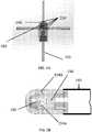
- FIG. 9illustrates a catheter 140 of the present disclosure oriented pointing at the viewer.
- a vial of solution that fluoresces at the same wavelengths as NADHis held next to the catheter 140, light pathways that emanate radially from the distal tip 148 are interacting with the vial of solution. The pathways emanating from the opposite side of the distal tip 148 are not visible due to lack of fluorescence.
- the system 100may also include an irrigation system 170.
- the irrigation system 170pumps saline into the catheter to cool the tip electrode during ablation therapy. This may help to prevent steam pops and char (i.e. clot that adheres to the tip that may eventually dislodge and cause a thrombolytic event) formation.
- the fluid flowmay clear the opening in the distal tip 148 of any blood that otherwise would otherwise absorb the illumination light.
- the irrigation system 170may be connected to the one or more openings in the distal tip 148 and can be used, for example, for flushing the openings with fluid to clear the tip of blood, cooling the tissue-electrode interface, prevention of thrombus formation, among many other possible uses.
- the irrigation fluidis maintained at a positive pressure relative to pressure outside of the catheter for continuous flushing of the one or more openings 154.
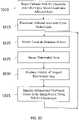
- the catheter 140is inserted into the area of heart tissue affected by the atrial fibrillation, such as the pulmonary vein / left atrial junction or another area of the heart (step 1010).
- Bloodmay be removed from the visual field, for example, by irrigation.
- the affected areamay be illuminated by ultra-violet light reflected from the light directing member 160 (step 1015).
- Tissue in the illuminated areamay be ablated (step 1020), either before, after, or during illumination. Either point-to-point RF ablation or cryoablation or laser or other known ablation procedures may be employed using the systems of the present disclosure.
- the illuminated areamay be imaged with the light directing member receiving the light from the tissue and directing such light to the optical fiber, which can then pass the light to the spectrometer (step 1025).
- NADHnicotinamide adenine dinucleotide
- the methods of the present disclosurerely on imaging of the fluorescence emission of NADH, which is a reduced form of nicotinamide adenine dinucleotide (NAD+).
- NADHnicotinamide adenine dinucleotide
- NADHnicotinamide adenine dinucleotide
- NADHnicotinamide adenine dinucleotide
- NADH fluorescencehas been studied for its use in monitoring cell metabolic activities and cell death.
- NADH fluorescence intensityAs an intrinsic biomarker of cell death (either apoptosis or necrosis) monitoring.
- NADHis autofluorescent in response to UV excitation whereas NAD+ is not.
- NADHhas a UV excitation peak of about 340-360 nm and an emission peak of about 460 nm.
- the methods of the present disclosuremay employ excitation wavelengths between about 330 to about 370 nm. With the proper instrumentation, it is thus possible to image the emission wavelengths as a real-time measure of hypoxia as well as necrotic tissue within a region of interest.
- a relative metriccan be realized with a grayscale rendering proportionate to NADH fluorescence.
- NADH levelsUnder hypoxic conditions, the oxygen levels decline. The subsequent fNADH emission signal may increase in intensity indicating an excess of mitochondrial NADH. If hypoxia is left unchecked, full attenuation of the signal will ultimately occur as the affected cells along with their mitochondria die. High contrast in NADH levels may be used to identify the perimeter of terminally damaged ablated tissue.
- NADHmay be excited by the UV light from the light source, such as a UV laser.
- NADH in the tissue specimenabsorbs the excitation wavelengths of light and emits longer wavelengths of light.
- the emission lightmay be collected and passed back to the spectrometer, and a display of the imaged illuminated area may be produced on a display (step 1030), which is used to identify the ablated and unablated tissue in the imaged area based on the amount of NADH florescence (step 1035).
- the sites of complete ablationmay appear as completely dark area due to lack of fluorescence. Accordingly, the areas of ablation may appear markedly darker when compared to the surrounding unablated myocardium, which has a lighter appearance.
- This featuremay enhance the ability to detect the ablated areas by providing marked contrast to the healthy tissue and even more contrast at the border zone between ablated and healthy tissue.
- This border areais the edematous and ischemic tissue in which NADH fluorescence becomes bright white upon imaging.
- the border zonecreates a halo appearance around the ablated central tissue.
- FIG. 10illustrates the steps being performed sequentially, many of the steps may be performed simultaneously or nearly simultaneously, or in a different order than shown in FIG. 10 .
- the ablation, imaging and displaycan occur at the same time, and the identification of the ablated and unablated tissue can occur while ablating the tissue.
- the system of the present disclosurecomprises a catheter, a light source, and a light measuring instrument.
- the systemfurther comprises an optical detection system having an optical detection fiber, the optical detection system being independent or immune from electrical or RF energy noise.
- the optical detection fiberdoes not conduct electrically and an RF energy does not produce electromagnetic energy in a range of interest to the system.
- the systemis adapted to optically interrogate a catheter environment in a biologic system.
- the systemis adapted to optically interrogate in real-time, via an NADH fluorescence, the catheter environment to determine or assess one or more of a complete or a partial immersion of an electrode in a blood pool.
- the optical systemcan detect, by inference, that the catheter tip is completely or partially immersed in the blood pool. The reason for this is because unlike the tissue or vasculature that return a positive optical signature, the blood completely absorbs the illumination light at this wavelength and thus returns a null optical signature. This feature of complete absorption provides optical isolation and therefore noise insulation.
- the instrumentcan use this situation for optical calibration and the elimination of stray optical signatures coming from the catheter itself.
- the systemmay be used for a qualitative and or a quantitative contact assessment between a catheter tip and a tissue, a qualitative and or a quantitative assessment of a catheter contact stability, an ablation lesion formation in real time, an ablation lesion progression monitoring, a determination of when to terminate a lesion, an identification of edematous zones which usually occur on a periphery of an ablation site and which can be associated with an incomplete ablation lesion, an ablation lesion depth, a cross-sectional area of the lesion, a temperature of the lesion, a recognition of steam formation or another physiologic parameter change to predict the onset of a steam pop, a formation of a char at a tip electrode during or after the ablation lesion formation, a detection of ischemia, a detection of a level of the ischemia, an ablation lesion assessment post lesion formation, an identification of edematous zones for re
- the systemis adapted to optically interrogate a tissue parameter of an NADH fluorescence (fNADH).
- fNADHNADH fluorescence
- the systemis adapted to optically interrogate a tissue, wherein the system analyzes parameters including a metabolic state of the tissue as well as a tissue composition of the tissue.
- the systemis adapted to illuminate a tissue with a wavelength wherein illuminating leads to several optical responses.
- the optical responsescomprises a myocardium containing NADH fluorescing if it is in a healthy metabolic state.
- other tissuessuch as collagen or elastin, fluoresce at different wavelengths, and the system uses a measurement of this information to determine a composition (i.e. collagen or elastin) of the tissue in contact with the catheter.
- the compositioncomprises myocardium, muscle, and myocardial structures such as valves, vascular structures, and fibrous or anatomical components.
- the compositioncomprises collagen, elastin, and other fibrous or support structures.
- a catheter of the present disclosurecomprises a catheter body, a tip electrode, and one or more sensing electrodes.
- the catheterfurther comprises one or more zones of different flexibility, the zones of flexibility being in combination with a deflection mechanism adapted to allow a distal portion of the catheter to be bent for ease of navigation for a physician.
- the zones of flexibilityare located at the distal portion of the catheter, while a main body of the catheter is kept relatively stiff for pushability.
- the main body of the catheter bodyis flexible so that the physician can use a robotic system for catheter navigation.
- the catheteris flexible and capable of being manipulated within a catheter sheath manually or robotically.
- the catheterfurther comprises a deflection mechanism adapted to deflect the catheter tip for navigation.
- the deflection mechanismcomprises one or more pull wires that are manipulated by a catheter handle and which deflect the distal portion of the catheter in one or more directions or curve lengths.
- the catheterfurther comprises a temperature sensor, the temperature sensor being integral to the distal tip of the electrode.
- the catheterfurther comprises one or more ultrasound transducers, the ultrasound transducers being located in the distal section of the catheter, and preferably in the tip of the distal electrode. The ultrasonic transducers are adapted to assess a tissue thickness either below or adjacent to the catheter tip.
- the cathetercomprises multiple transducers adapted to provide depth information covering a situation where the catheter tip is relatively perpendicular to a myocardium or relatively parallel to a myocardium.
- the catheterfurther comprises an irrigation means for the purposes of flushing catheter openings with an irrigation fluid to clear the tip of blood, cooling a tissue-electrode interface, preventing a thrombus formation, and dispersing an RF energy to a greater zone of tissue, thus forming larger lesions than non-irrigated catheters.
- the irrigating fluidis maintained within the catheter tip at a positive pressure relative to outside of the tip, and is adapted for continuous flushing of the openings.
- the catheterfurther comprises an electric, magnetic or electromagnetic location or navigation sensor for locating and navigating the catheter.
- the sensoris adapted to locate the tip of the catheter in a navigation system of any one of several catheter or system manufacturers.
- the sensorcan send or receive energy from a source location and compute location through triangulation or other means.
- the cathetercomprises more than one sensor or transducer adapted to render a position of the catheter body and a curvature of the catheter body on a navigation system display.
- a catheter adapted to ablate tissuecomprises a catheter body, and a tip electrode adapted to ablate a tissue.
- the catheterfurther comprises at least one optical waveguide adapted to deliver light energy to the tissue, and one or more optical waveguides adapted to receive light energy from the tissue.
- the catheterfurther comprises a single optical waveguide adapted to deliver light energy to the tissue and receive light energy from the tissue.
- the catheteris adapted for an ablation energy, the ablation energy being one or more of RF energy, cryo energy, laser, chemical, electroporation, high intensity focused ultrasound or ultrasound, and microwave.
- the tip of the cathetercomprises a first electrode adapted for sensing electrical activity of the tissue, a second electrode adapted for transmitting or conducting ablation energy or chemical, a light directing member to direct a light in one or more directions simultaneously, one or more openings for the transmission and receiving of light energy, one or more openings for an irrigation fluid to flow from the tip, and one or more openings adapted for transmitting and receiving light as well as concomitantly flowing irrigation fluid from the tip.
- the tip of the cathetercomprises an electrically conductive material, adapted to allow the first electrode to sense the electrical activity of the tissue in contact with the catheter.
- the tipfurther comprises an electrode adapted for transmitting or conducting ablation energy or a chemical energy.
- the tipis adapted to conduct RF energy to the adjacent tissue.
- the tipcomprises an optically transparent material allowing conduction of laser ablation energy to the adjacent tissue.
- the tipcomprises a plurality of holes adapted to transmit a chemical used to alter cells of the tissue or of a tissue in close proximity to the tip.
- the openings for transmitting and receiving lightare in the distal tip.
- the tipcomprises additional holes adapted to cool the tip with a fluid during an application of ablation energy.
- the tipfurther comprises at least one opening adapted to allow a directed light energy to illuminate the tissue, and to allow the light energy to return from the tissue to the catheter.
- the tipcomprises at least one opening in the distal tip for illuminating a tissue along a longitudinal axis of the catheter.
- the light energyis directed in a manner that is dependent upon a light directing member having a central lumen allowing a portion of the light to be directed in a longitudinal direction.
- the tipfurther comprises at least one opening in the distal tip for illuminating the tissue in a radial axis with respect to the catheter.
- the tipis adapted to direct the light by splitting the primary light source into specific multiple beams using the light directing member.
- the primary light sourceis a laser, the laser adapted to send a light beam down an optical fiber to the light directing member, wherein the light beam is sent in one or more directions, including straight ahead relative to the tip, to make sure a structure adjacent to the catheter is illuminated.
- a structure that is illuminatedwill transmit optical energy back to the catheter tip and to the light directing member, which in turn reflects the returned light back up the fiber to a spectrometer.
- the tipis configured to direct the light energy independent of any polishing of the interior of the illumination cavity. In some embodiments, the directing of light energy does not depend on the use of an interior wall of the illumination cavity.
- a catheter adapted to support fNADHcomprising one or more ultrasound transducers.
- the catheteris adapted to measure a wall thickness of an area of interest.
- the catheteris adapted to assess a metabolic state of the tissue throughout the wall thickness.
- the catheterfurther comprises ultrasonic transducers adapted to measure cardiac wall thickness and adapted to assess a metabolic state of the myocardium during an application of an RF energy.
- the catheteris adapted to identify any metabolically active tissue for the purposes of identifying electrical gaps in lesions.
- the cathetercomprises a light-directing component adapted to send light in one or more radial directions and axially simultaneously.
- the catheterfurther comprises a separate or a modular component of the tip electrode, wherein an light directing member is integrated into the tip of the electrode during.
- the light directing memberhas a centrally located lumen for light to pass in the axial direction.
- the light directing memberis keyed to facilitate alignment of a facet of the light directing member to openings of the catheter tip permitting a transfer of light energy.
- the light directing memberis integrated into the catheter tip via a snap-fitting, welding, soldering, or gluing into a keyed position in the catheter tip.
- the light directing memberis keyed to facilitate a correct alignment of one or more reflecting facets and one or more light ports in the tip of the catheter.
- the light directing memberis a separate component that is oriented into the catheter tip, adapted to provide a light path through the tip, inline with a longitudinal axis of the catheter.
- the light directing memberprotrudes through the tip and can be welded on the distal side of the tip so that the welding does not interfere or damage a reflective surface of the light directing member.
- the light directing membercomprises polished stainless steel.
- the light directing membercomprises platinum or platinum alloys, a material identical to the tip, any material with a reflective surface capable of reflecting or splitting light, or a material that does not fluoresce when illuminated from about 310nm to about 370nm.
- the light directing memberis larger than any aperture of the tip electrode to ensure the light directing member cannot escape through said aperture.
- the light directing membermay be optimized to provide the optimum number of facets and the optimum optical path for efficiency. These attributes can be traded off against the desired radial coverage.
- the radial coveragecan be designed so that at least one opening in the side wall of the distal tip is pointed at the myocardium when the tip is parallel to the heart tissue.
- the opening in the front wall of the distal tipmay ensure that light is both transmitted and received when the catheter tip is more or less orthogonal to the myocardial surface.
- the light directing memberis provided with 3 to 4 facets.
- a catheter of the present disclosurecomprises of a catheter body with the following components: a catheter with a distal tip positioned at a distal end of the catheter body, the distal tip defining a light chamber, the distal tip having one or more openings for exchange of light energy between the light chamber and tissue, and a the same catheter with a light directing member disposed within the light chamber, the light directing member being configured to direct the light energy to and from the tissue through the one or more openings in the distal tip.
- the cathetercomprises of one or more optical waveguides extending into the light chamber to deliver light to and from the light chamber.
- the catheterhas a light directing member and the one or more openings are configured to enable illumination of tissue in the radial and the axial directions.
- the catheterhas a distal tip that has a dome shaped front wall and straight side walls.
- the catheterhas one or more openings that are disposed along sidewalls of the distal tip.
- the catheterhas one or more openings that are disposed circumferentially along the distal tip.
- the catheterhas one or more openings that are provided in multiple rows along side walls of the distal tip.
- the catheterhas a distal tip that is comprised of a tissue ablation electrode.
- the catheterhas a light directing member that is configured to direct light radially through the one or more openings. In some embodiments, the catheter has a light directing member that is comprised of multiple facets. In some embodiments, the catheter has a light directing member that is comprised of multiple facets, wherein the facets are equally spaced. In some embodiments, the catheter has a light directing member that is comprised of multiple facets, wherein the number of the facets corresponds to the number of the openings along side walls of the distal tip. In some embodiments, the catheter has a light directing member that is shaped to reflect the light energy at an angle relative to the longitudinal axis of the catheter.
- the catheterhas a light directing member that is comprised of a single-faceted mirror. In some embodiments, the catheter has a light directing member that is rotatable with respect to the light chamber. In some embodiments, the catheter has a light directing member that is comprised of one or more through-holes and the distal tip is comprised of one or more openings disposed on a front wall of the distal tip to enable passage of light in longitudinal direction through the light directing member and the one or more openings of the front wall.
Landscapes
- Health & Medical Sciences (AREA)
- Life Sciences & Earth Sciences (AREA)
- Surgery (AREA)
- Engineering & Computer Science (AREA)
- Nuclear Medicine, Radiotherapy & Molecular Imaging (AREA)
- Animal Behavior & Ethology (AREA)
- General Health & Medical Sciences (AREA)
- Veterinary Medicine (AREA)
- Public Health (AREA)
- Biomedical Technology (AREA)
- Molecular Biology (AREA)
- Medical Informatics (AREA)
- Heart & Thoracic Surgery (AREA)
- Physics & Mathematics (AREA)
- Pathology (AREA)
- Otolaryngology (AREA)
- Oral & Maxillofacial Surgery (AREA)
- Plasma & Fusion (AREA)
- Biophysics (AREA)
- Radiology & Medical Imaging (AREA)
- Cardiology (AREA)
- Gynecology & Obstetrics (AREA)
- Chemical & Material Sciences (AREA)
- Chemical Kinetics & Catalysis (AREA)
- General Chemical & Material Sciences (AREA)
- Electromagnetism (AREA)
- Optics & Photonics (AREA)
- Laser Surgery Devices (AREA)
- Surgical Instruments (AREA)
- Endoscopes (AREA)
- Robotics (AREA)
Description
- The present disclosure generally relates to catheters, and more particularly ablation and visualization catheters.
- Atrial fibrillation (AF) is the most common sustained arrhythmia in the world, which currently affects millions of people. In the United States, AF is projected to affect 10 million people by the year 2050. AF is associated with increased mortality, morbidity, and an impaired quality of life, and is an independent risk factor for stroke. The substantial lifetime risk of developing AF underscores the public heath burden of the disease, which in the U.S. alone amounts to an annual treatment cost exceeding $7 billion.
- Most episodes in patients with AF are known to be triggered by focal electrical activity originating from within muscle sleeves that extend into the Pulmonary Veins (PV). Atrial fibrillation may also be triggered by focal activity within the superior vena cava or other atrial structures, i.e. other cardiac tissue within the heart's conduction system. These focal triggers can also cause atrial tachycardia that is driven by reentrant electrical activity (or rotors), which may then fragment into a multitude of electrical wavelets that are characteristic of atrial fibrillation. Furthermore, prolonged AF can cause functional alterations in cardiac cell membranes and these changes further perpetuate atrial fibrillation.
- Radiofrequency ablation (RFA), laser ablation and cryo ablation are the most common technologies of catheter-based mapping and ablation systems used by physicians to treat atrial fibrillation. Physicians use a catheter to direct energy to either destroy focal triggers or to form electrical isolation lines isolating the triggers from the heart's remaining conduction system. The latter technique is commonly used in what is called pulmonary vein isolation (PVI). However, the success rate of the AF ablation procedure has remained relatively stagnant with estimates of recurrence to be as high as 30% to 50% one-year post procedure. The most common reason for recurrence after catheter ablation is one or more gaps in the PVI lines. The gaps are usually the result of ineffective or incomplete lesions that may temporarily block electrical signals during the procedure but heal over time and facilitate the recurrence of atrial fibrillation.
- Therefore, there is a need for system and method for forming and verifying proper lesions to improve outcomes and reduce costs.
- From
US 2009/0131931A1 a catheter with an omnidirectional optical tip is known, which enables light measurements of tissue and wherein the catheter tip is designed to isolate illumination and collection paths such that light exits the catheter tip and travels through the tissue of interest before returning to the catheter tip and ensures diffusion of the illumination light within the medium of interest. Furthermore, fromEP 2 889 013 A1 a catheter for optical spectroscopy for measuring tissue contact area is known with separate waveguides and a distal tip with a plurality of apertures.US 2006/0089636 A1 discloses methods and devices for transurethral needle ablation using ultrasound visualization.US 2007/0270717 A1 describes the use of transparent balloons together with fibers having a particular numerical aperture and a multi-faceted reflector to receive light from a large area. - The invention is as defined by independent claim 1. Dependent claims disclose exemplary embodiments.
- According to some aspects of the present disclosure, there is provided a catheter for visualizing ablated tissue comprising: a catheter body; a distal tip positioned at a distal end of the catheter body, the distal tip defining a illumination cavity, the distal tip having one or more openings for exchange of light energy between the illumination cavity and tissue; a light directing member disposed within the illumination cavity, the light directing member being configured to direct the light energy to and from the tissue through the one or more openings in the distal tip.
- In some embodiments, the distal tip of the catheter may be configured to deliver ablation energy to the tissue, the ablation energy being selected from a group consisting of radio frequency (RF) energy, microwave energy, electrical energy, electromagnetic energy, cryoenergy, laser energy, ultrasound energy, acoustic energy, chemical energy, thermal energy and combinations thereof.
- In some embodiments, the light directing member and the one or more openings are configured to enable illumination of tissue in a radial direction and an axial direction with respect to a longitudinal axis of the catheter. In some embodiments, the one or more openings are disposed along side walls of the distal tip and the light directing member is shaped to split light energy and specifically direct the light energy at an angle relative to the longitudinal axis of the catheter through the one or more openings. In some embodiments, the light directing member comprises one or more through-holes and the distal tip comprises one or more openings disposed on a front wall of the distal tip to enable passage of light in longitudinal direction through the light directing member and the one or more openings of the front wall. In some embodiments, the catheter may further comprise an ultrasound transducer.
- According to some aspects of the present disclosure, there is provided a system for visualizing ablated tissue comprising a catheter comprising a catheter body; a distal tip positioned at a distal end of the catheter body, the distal tip defining a illumination cavity, the distal tip having one or more openings for exchange of light energy between the illumination cavity and tissue; a light directing member disposed within the illumination cavity, the light directing member being configured to direct the light energy to and from the tissue through the one or more openings in the distal tip; a light source; a light measuring instrument; and one or more optical fibers in communication with the light source and the light measuring instrument and extending through the catheter body into the illumination cavity of the distal tip, wherein the one or more optical fibers are configured to pass light energy from the light source to the light directing member for illuminating tissue outside the distal tip and the one or more optical fibers are configured to relay light energy reflected from the tissue to the light measuring instrument.
- Not according to the invention, there is provided a method for visualizing ablated tissue comprising: advancing a catheter to a cardiac tissue in need of ablation, the catheter comprising a catheter body; a distal tip positioned at a distal end of the catheter body, the distal tip defining a illumination cavity, the distal tip having one or more openings for exchange of light between the illumination cavity and tissue; a light directing member disposed within the illumination cavity, the light directing member being configured to direct the light to and from the tissue through the one or more openings in the distal tip; causing the light directing member to direct light through the one or more openings in the distal tip of the catheter to excite nicotinamide adenine dinucleotide hydrogen (NADH) in an area of the cardiac tissue including ablated cardiac tissue and non-ablated cardiac tissue; collecting light reflected from the cardiac tissue through the one or more openings and directing the collected light to a light measuring instrument; imaging the area of the cardiac tissue to detect NADH fluorescence of the area of the cardiac tissue; and producing a display of the imaged, illuminated cardiac tissue, the display illustrating the ablated cardiac tissue as having less fluorescence than non-ablated cardiac tissue.
- In some embodiments not according to the invention, the method may further include ablating tissue with the distal tip prior to imaging the tissue, and ablating additional non-ablated cardiac tissue identified by distinguishing between the ablated cardiac tissue and the non-ablated cardiac tissue based on the amount of fluorescence.
- The presently disclosed embodiments will be further explained with reference to the attached drawings, wherein like structures are referred to by like numerals throughout the several views. The drawings shown are not necessarily to scale, with emphasis instead generally being placed upon illustrating the principles of the presently disclosed embodiments.
FIG. 1 is an embodiment of an ablation visualization system of the present disclosure.FIG. 2 is a diagram of a visualization system for use in connection with an ablation visualization system of the present disclosure.FIG. 3 illustrates an embodiment of a distal tip of a catheter of the present disclosure.FIG. 4A and FIG. 4B illustrate an embodiment of a light directing member of a catheter of the present disclosure.FIG. 5A and FIG. 5B illustrate an embodiment of a distal tip of a catheter of the present disclosure.FIG. 6A, FIG. 6B, FIG. 6C and FIG. 6D illustrate an optical fiber aligner of a catheter of the present disclosure.FIG. 7A and FIG. 7B illustrate an embodiment of a light directing member of the present disclosure.FIGs. 8A-8D illustrate various embodiments of a catheter of the present disclosure.FIG. 9 illustrates an embodiment of a catheter of the present disclosure illuminating a fluorescent solution.FIG. 10 is a flow chart of a method of using a system of the present disclosure.- While the above-identified drawings set forth presently disclosed embodiments, other embodiments are also contemplated, as noted in the discussion. This disclosure presents illustrative embodiments by way of representation and not limitation.
- The present disclosure generally relates to systems and methods for applying radio frequency, laser or cryo ablation energy to the body to form therapeutic lesions. In some embodiments, the systems and methods of the present disclosure may be employed for imaging tissue using nicotinamide adenine dinucleotide hydrogen (NADH) fluorescence (fNADH). By way of a non-limiting example, the present systems and methods may be used during the treatment of Atrial Fibrillation (AF).
- In general, the system may include a catheter with an optical system for exchanging light between tissue and the catheter. In some embodiments, the instant systems allow for direct visualization of the tissue's NADH fluorescence, or lack thereof, induced by ultraviolet (UV) excitation. The fluorescence signature returned from the tissue can be used to determine the presence or absence of ablation lesions in illuminated tissue as well as information about a lesion as it is forming during ablation. This optical tissue interrogation can be performed on various tissue types, including, without limitation, various cardiac tissues, endocardial tissue, epicardial tissue, myocardium tissue, valves, vascular structures, and fibrous and anatomical structures. The systems and methods of the present disclosure may be used to analyze tissue composition including, but not limited to the presence of collagen and elastin. However, the presently disclosed methods and systems may also be applicable for analyzing lesions in other tissue types. The lesions to be analyzed may be created by application of ablation energy during the ablation procedure. In some embodiments, existing lesions, created by ablation or by other means, may also be analyzed using methods and systems disclosed herein.
- In reference to
FIG. 1 , the system for providingablation therapy 100 may include anablation therapy system 110, avisualization system 120, and acatheter 140. In some embodiments, thesystem 100 may also include anirrigation system 170. The system may also include adisplay 180, which can be a separate display or a part of thevisualization system 120, as described below. - In some embodiments, the
ablation therapy system 110 is designed to supply ablation energy to thecatheter 140. Theablation therapy system 110 may include one or more energy sources that can generate radiofrequency (RF) energy, microwave energy, electrical energy, electromagnetic energy, cryoenergy, laser energy, ultrasound energy, acoustic energy, chemical energy, thermal energy or any other type of energy that can be used to ablate tissue. In some embodiments, the system includes an RF generator, anirrigation pump 170, an irrigated-tip ablation catheter 140, and thevisualization system 120. - In reference to
FIG. 2 , thevisualization system 120 may include alight source 122, alight measuring instrument 124, and acomputer system 126. - In some embodiments, the
light source 122 may have an output wavelength within the target fluorophore (NADH, in some embodiments) absorption range in order to induce fluorescence in healthy myocardial cells. In some embodiments, thelight source 122 is a solid-state laser that can generate UV light to excite NADH fluorescence. In some embodiments, the wavelength may be about 355nm or 355 nm +/- 30 nm. In some embodiments, thelight source 122 can be a UV laser. Laser-generated UV light may provide much more power for illumination and may be more efficiently coupled into a fiber-based illumination system, as is used in some embodiments of the catheter. In some embodiments, the instant system can use a laser with adjustable power up to 150 mW. - The wavelength range on the
light source 122 may be bounded by the anatomy of interest, a user specifically choosing a wavelength that causes maximum NADH fluorescence without exciting excessive fluorescence of collagen, which exhibits an absorption peak at only slightly shorter wavelengths. In some embodiments, thelight source 122 has a wavelength from 300nm to 400nm. In some embodiments, thelight source 122 has a wavelength from 330nm to 370nm. In some embodiments, thelight source 122 has a wavelength from 330nm to 355nm. In some embodiments, a narrow-band 355 nm source may be used. The output power of thelight source 122 may be high enough to produce a recoverable tissue fluorescence signature, yet not so high as to induce cellular damage. Thelight source 122 may be coupled to an optical fiber to deliver light to thecatheter 140, as will be described below. - In some embodiments, the systems of the present disclosure may utilize a spectrometer as the
light measuring instrument 124. In some embodiments, thelight measuring instrument 124 may comprise a camera connected to thecomputer system 126 for analysis and viewing of tissue fluorescence. In some embodiments, the camera may have high quantum efficiency for wavelengths corresponding to NADH fluorescence. One such camera is an Andor iXon DV860. Thespectrometer 124 may be coupled to an imaging bundle that can be extended into thecatheter 140 for visualization of tissue. In some embodiments, the imaging bundle for spectroscopy and the optical fiber for illumination may be combined. An optical bandpass filter of between 435nm and 485nm, in some embodiments, of 460nm, may be inserted between the imaging bundle and the camera to block light outside of the NADH fluorescence emission band. In some embodiments, other optical bandpass filters may be inserted between the imaging bundle and the camera to block light outside of the NADH fluorescence emission band selected according to the peak fluorescence of the tissue being imaged. - In some embodiments, the
light measuring instrument 124 may be a CCD (charge-coupled device) camera. In some embodiments, thespectrometer 124 may be selected so it is capable of collecting as many photons as possible and that contributes minimal noise to the image. Usually for fluorescence imaging of live cells, CCD cameras should have a quantum efficiency at about 460 nm of at least between 50-70%, indicating that 30-50% of photons will be disregarded. In some embodiments, the camera has quantum efficiency at 460 nm of about 90%. The camera may have a sample rate of 80 KHz. In some embodiments, thespectrometer 124 may have a readout noise of 8 e- (electrons) or less. In some embodiments, thespectrometer 124 has a minimum readout noise of 3e-. Other light measuring instruments may be used in the systems and methods of the present disclosure. - The
optical fiber 150 can deliver the gathered light to a long pass filter that blocks the reflected excitation wavelength of 355nm, but passes the fluoresced light that is emitted from the tissue at wavelengths above the cutoff of the filter. The filtered light from the tissue can then be captured and analyzed by a high-sensitivity spectrometer 124. Thecomputer system 126 acquires the information from thespectrometer 124 and displays it to the physician. Thecomputer 126 can also provide several additional functions including control over thelight source 122, control over thespectrometer 124, and execution of application specific software. - In some embodiments, the digital image that is produced by analyzing the light data may be used to do the 2D and 3D reconstruction of the lesion, showing size, shape and any other characteristics necessary for analysis. In some embodiments, the image bundle may be connected to the
spectrometer 124, which may generate a digital image of the lesion being examined from NADH fluorescence (fNADH), which can be displayed on thedisplay 180. In some embodiment, these images can be displayed to the user in real time. The images can be analyzed by using software to obtain real-time details (e.g. intensity or radiated energy in a specific site of the image) to help the user to determine whether further intervention is necessary or desirable. In some embodiments, the NADH fluorescence may be conveyed directly to thecomputer system 126. - In some embodiments, the optical data acquired by the light measuring instrument can be analyzed to provide information about lesions during and after ablation including, but not limited to lesion depth and lesion size. In some embodiments, data from the light measuring instrument can be analyzed to determine if the
catheter 140 is in contact with the myocardial surface and how much pressure is applied to the myocardial surface by the tip of the catheter. In some embodiments, data from thespectrometer 124 is analyzed to determine the presence of collagen or elastin in the tissue. In some embodiments, data from the light measuring instrument is analyzed and presented visually to the user via a graphical user interface in a way that provides the user with real-time feedback regarding lesion progression, lesion quality, myocardial contact, tissue collagen content, and tissue elastin content. - In some embodiments, the
system 100 of the present disclosure may further include anultrasound system 190. Thecatheter 140 may be equipped with ultrasound transducers in communication with the ultrasound system. In some embodiments, the ultrasound may show tissue depths, which in combination with the metabolic activity or the depth of lesion may be used to determine if definitively say if a lesion is in fact transmural or not. In some embodiments, thecatheter 140 may be equipped with location or navigation sensors in communication with a location ornavigation system 200, as is described below. - Referring back to
FIG. 1 , thecatheter 140 includes acatheter body 142 having aproximal end 144 and adistal end 146. Thecatheter body 142 may be made of a biocompatible material, and may be sufficiently flexible to enable steering and advancement of thecatheter 140 to a site of ablation. In some embodiments, thecatheter body 142 may have zones of variable stiffness. For example, the stiffness of thecatheter 140 may increase from theproximal end 144 toward thedistal end 146. In some embodiments, the stiffness of thecatheter body 142 is selected to enable delivery of thecatheter 140 to a desired cardiac location. In some embodiments, thecatheter 140 can be a steerable, irrigated radiofrequency (RF) ablation catheter that can be delivered through a sheath to the endocardial space, and in the case of the heart's left side, via a standard transseptal procedure using common access tools. Thecatheter 140 may include ahandle 147 at theproximal end 144. Thehandle 147 may be in communication with one or more lumens of the catheter to allow passage of instruments or materials through thecatheter 140. In some embodiments, thehandle 147 may include connections for the standard RF generator and irrigation system for therapy. In some embodiments, thecatheter 140 may also include one more adaptors configured to accommodate theoptical fiber 150 for illumination and spectroscopy. - In reference to
FIG. 3 , at thedistal end 146, thecatheter 140 may include adistal tip 148, having aside wall 156 and afront wall 158. Thefront wall 158 may be, for example, flat, conical or dome shaped. In some embodiments, thedistal tip 148 may be configured to act as an electrode for diagnostic purposes, such as electrogram sensing, for therapeutic purposes, such as for emitting ablation energy, or both. In some embodiments where ablation energy is required, thedistal tip 148 of thecatheter 140 could serve as an ablation electrode or ablation element. - In the embodiments where RF energy is implemented, the wiring to couple the
distal tip 148 to the RF energy source (external to the catheter) can be passed through a lumen of the catheter. Thedistal tip 148 may include a port in communication with the one or more lumens of the catheter. Thedistal tip 148 can be made of any biocompatible material. In some embodiments, if thedistal tip 148 is configured to act as an electrode, thedistal tip 148 can be made of metal, including, but not limited to, platinum, platinum-iridium, stainless steel, titanium or similar materials. - In reference to
FIG. 3 , an optical fiber or animaging bundle 150 is passed from thevisualization system 120, through thecatheter body 142, and into an illumination cavity orcompartment 152, defined by thedistal tip 148. Thedistal tip 148 is provided with one ormore openings 154 for exchange of light energy between theillumination cavity 152 and tissue. In some embodiments, even withmultiple openings 154, the function of thedistal tip 148 as an ablation electrode is not compromised. This light is delivered by thefiber 150 to thedistal tip 148, where it illuminates the tissue in the proximity of thedistal tip 148. This illumination light is either reflected or causes the tissue to fluoresce. The light reflected by and fluoresced from the tissue may be gathered by theoptical fiber 150 within thedistal tip 148 and carried back to thevisualization system 120. In some embodiments, the same optical fiber or bundle offibers 150 may be used to direct light to thelight directing member 160 to illuminate tissue outside thecatheter 140 in one or more directions and to collect light from the tissue. - In some embodiments, the one or
more openings 154 may be provided in theside wall 156 of thedistal tip 148, thefront wall 158, or both. In some embodiments, the one ormore openings 154 may be disposed circumferentially along thedistal tip 148 around the entire circumference of thedistal tip 148. In some embodiments, the one ormore openings 154 may be disposed equidistantly from one another. The number of the openings may be determined by the desired angle of viewing coverage. For example, with 3 openings equally spaced, illumination and returned light occur at 120-degree increments (360 degrees divided by 3). In some embodiments, the one ormore openings 154 may be provided in multiple rows along theside walls 156 of thedistal tip 148. In some embodiments, thedistal tip 148 may include 3 or 4 openings in theside wall 156. In some embodiments, a single opening may be provided in the center of thefront wall 158. In some embodiments,multiple openings 154 may be provided in thefront wall 158. In some embodiments, thedistal tip 148 is provided with 3 side openings and 1 front opening. The one ormore openings 154 may also serve as an irrigation port in connection with the irrigation system. In some embodiments light is only directed through some of theside openings 154. For example, in some embodiments there may exist 6 openings in theside wall 156, but light may be directed through only 3 of the openings, while the other openings may be used for irrigation. - To enable the light energy exchange between the
illumination cavity 152 and tissue over multiple paths (axially and radially with respect to the longitudinal central axis of the catheter), alight directing member 160 is provided in theillumination cavity 152. Thelight directing member 160 directs the illumination light to the tissue and direct the light returned through the one ormore openings 154 within thedistal tip 148 to theoptical fiber 150. Thelight directing member 160 may also be made from any biocompatible material with a surface that reflects light or can be modified to reflect light, such as for example, stainless steel, platinum, platinum alloys, quartz, sapphire, fused silica, metallized plastic, or other similar materials. In some embodiments, thelight directing member 160 may comprise a highly polished mirror. Not according to the invention, thelight directing member 160 may be conical (i.e. smooth). According to the invention, thelight directing member 160 is faceted with any number of sides. Thelight directing member 160 may be shaped to bend the light at any desired angle. In some embodiments, thelight directing member 160 may be shaped to reflect the light only through the one or more openings. In some embodiments, the material for thelight directing member 160 is chosen from materials that do not fluoresce when exposed to illumination between 310 nm to 370 nm. - In some embodiments, as shown in
FIG. 3 , thelight directing member 160 may include one ormore holes 162 through the centerline of the mirror, which allow illumination and reflected light to pass in both directions axially, directly in line with thecatheter 140. Such an axial path may be useful when the distal-most surface of thedistal tip 148 is in contact with the anatomy. The alternate radial paths may be useful when the anatomy will not allow the distal-most surface of thedistal tip 148 to be in contact with the target site as is sometimes the case in the left atrium of the patient during pulmonary vein isolation procedures, common in treating atrial fibrillation. In some embodiments, in all pathways, lensing may not be required and the optical system is compatible with theirrigation system 170 as the light passes through the cooling fluid, which is often saline. Theirrigation system 170 may also serve to flush the blood from theholes 162, thus keeping the optical components clean. - In reference to
FIG. 4A , thelight directing member 160 has afront face 164 with multiple,angled facets 166. In some embodiments, thelight directing member 160 may include 3 or 4 equidistant facets, although more or less facets may be used. In some embodiments, the number offacets 166 may correspond to the number of theopenings 154 in theside wall 156. In some embodiments, there may befewer facets 166 than theopenings 154 in theside wall 156. In some embodiments, as shown inFIG. 4B , thefacets 166 may be positioned at 45 degrees relative to central axis of the light directing member 160 (135 degrees relative to the axis of the catheter). In some embodiments, thefacets 166 may be positioned at greater or lesser angles than 45 degrees in order to direct light more distally or more proximally. - In reference to
FIG. 5A , the light directed onto thelight directing member 160 from theoptical fiber 150 is reflected by thelight directing member 160. Some of the reflected light may exit thedistal tip 148 through the one ormore openings 154 in theside wall 156 of thedistal tip 148. The light directing member may separate or split the light beam shined on the light directing member into multiple beams and specifically directing the split beams to exit through the correspondingopenings 154. In this manner, the intensity of light from the light source may be substantially conserved and the intensity of illuminating the tissue may be increased. Otherwise, if the light is diffused through the illumination cavity, without the light directing member focusing the light into theopenings 154, the intensity of the light illuminating the tissue may be insufficient for tissue imaging. In addition, in some embodiments, the light directing member is configured to collect light beams reflected from the tissue and to direct them the optical fiber, which can them relay them to the light measuring instrument. In some embodiments, the beams received from tissue may be combined before being sent to the optical fiber. In some embodiments, all light delivered into the illumination cavity may be directed by the light directing member to exit theillumination cavity 152 through theopenings 154. In addition, light can also pass through theholes 162 in thelight directing member 160 and through theopenings 154 in thefront wall 158 of thedistal tip 148. By aligning thelight directing member 160, theoptical fiber 150 and theopenings 154, the intensity of light to tissue may be adjusted and maximized. The angle of thefacets 166, the size, number, and location of theopenings 154, and the size, number, and location of holes in thelight directing member 160 can be adjusted and optimized to provide the desired balance of light returned from tissue illuminated at thedistal tip 148 of the catheter via the openings in light directingmember 160 and the light returned from tissue illuminated via theopenings 154. - As shown in
FIG. 5B , in some embodiments, theopenings 154 may be directly in line with thefacets 166 of thelight directing member 160. In some embodiments, the correspondence between theopenings 154 and thefacets 166 may be different than 1:1. In some embodiments, thecatheter 140 may include 3 openings or 4 openings corresponding to 3 facets or 4facets 166, respectively, of thelight directing member 160. It should be noted that, in some embodiments, some of theopenings 154 may not be used for exchange of light due to the shape and orientation of theopenings 154 and thelight directing member 160, but are only used for irrigation purposes. As shown inFIG. 5B , theopenings 154a may be aligned with thefacets 166 for exchange of light, whileopenings 154b are not aligned with thefacets 166, and thus are used primarily for irrigation, even if additional light is exchanged. - In reference to
FIG. 6A and FIG. 6B , in some embodiments, afiber aligner 168 may be provided in thedistal tip 148 to align theoptical fiber 150 with thelight directing member 160. Thefiber aligner 168 may include afiber lumen 170 through which theoptical fiber 150 may be advanced to align theoptical fiber 150 with thelight directing member 160. In some embodiments, the central axis of theoptical fiber 150 may be aligned with the center axis of thelight directing member 160 to uniformly illuminate thefacets 166 of thelight directing member 160 and to allow illumination in the central hole for illumination and return in the longitudinal direction. For example, thefiber lumen 170 may extend along the center axis of thefiber aligner 168 to center theoptical fiber 150 relative to thelight directing member 160. The position of the fiber in thefiber aligner 168 may be optimized to distribute light as desired between the central hole in thelight directing member 160 and theopenings 154 to maximize tissue fluorescence for the ablation application of interest. - As shown in
FIG. 6C and FIG. 6D , thefiber aligner 168 may be inserted into thedistal tip 148. When theoptical fiber 150 is advanced through thefiber lumen 170 of thefiber aligner 168, theoptical fiber 150 will assume a desired orientation and position relative to thelight directing member 160. - Referring back to
FIG. 6B , in some embodiments, thefiber aligner 168 may include one ormore cut outs 172 and one ormore ports 174. In this manner, when thefiber aligner 168 is inserted into thedistal end 144 of thecatheter 140, thecut outs 172 and theports 174 allow passage of instruments and materials (such as, for example, irrigation fluid and electrode wiring for ablation into the distal tip 148). - In reference to
FIG. 7A and FIG. 7B , thelight directing member 160 may be provided with akey member 174 to help align thefacets 166 of thelight directing member 160 with the one ormore openings 154. The angle of the facets on thelight directing member 160 may align with theopenings 154 on thedistal tip 148. If they are misaligned, the light path may become inefficient. To ensure this alignment, in some embodiments, thelight directing member 160 and thedistal tip 148 have symmetrical key features so that the alignment of thefacets 166 and the openings are deterministic. Once in place, a variety of technologies can be used to secure thelight directing member 160 to thedistal tip 148. - In reference to
FIG. 8A and FIG. 8B , in some embodiments, thelight directing member 160 may comprise a single faceted mirror that is capable of illuminating and receiving light in only one direction at a time. In some embodiments, suchlight directing member 160 may be rotatable relative to thecatheter 140 to align theopening 154 in theside wall 156 with the target site. There are many ways of implementing a rotating mirror including, without limitation, a hydraulic turbine mechanism, having a torqueing mechanism in thehandle 147 of thecatheter 140 coupled to the light directing mirror. In reference toFIG. 8B , in some embodiments, a stationary mirror may be provided with a conical as opposed to a faceted geometry.FIG. 8C and FIG. 8D illustrate another embodiment of thelight directing member 160 with 6 facets. FIG. 9 illustrates acatheter 140 of the present disclosure oriented pointing at the viewer. When a vial of solution that fluoresces at the same wavelengths as NADH is held next to thecatheter 140, light pathways that emanate radially from thedistal tip 148 are interacting with the vial of solution. The pathways emanating from the opposite side of thedistal tip 148 are not visible due to lack of fluorescence.- As noted above, the
system 100 may also include anirrigation system 170. In some embodiments, theirrigation system 170 pumps saline into the catheter to cool the tip electrode during ablation therapy. This may help to prevent steam pops and char (i.e. clot that adheres to the tip that may eventually dislodge and cause a thrombolytic event) formation. For the proposed optical system, the fluid flow may clear the opening in thedistal tip 148 of any blood that otherwise would otherwise absorb the illumination light. - The
irrigation system 170 may be connected to the one or more openings in thedistal tip 148 and can be used, for example, for flushing the openings with fluid to clear the tip of blood, cooling the tissue-electrode interface, prevention of thrombus formation, among many other possible uses. In some embodiments, the irrigation fluid is maintained at a positive pressure relative to pressure outside of the catheter for continuous flushing of the one ormore openings 154. - In reference to
FIG. 10 , operation of thesystems 100 of the present disclosure is illustrated. Initially, thecatheter 140 is inserted into the area of heart tissue affected by the atrial fibrillation, such as the pulmonary vein / left atrial junction or another area of the heart (step 1010). Blood may be removed from the visual field, for example, by irrigation. The affected area may be illuminated by ultra-violet light reflected from the light directing member 160 (step 1015). Tissue in the illuminated area may be ablated (step 1020), either before, after, or during illumination. Either point-to-point RF ablation or cryoablation or laser or other known ablation procedures may be employed using the systems of the present disclosure. - Still referring to
FIG. 10 , the illuminated area may be imaged with the light directing member receiving the light from the tissue and directing such light to the optical fiber, which can then pass the light to the spectrometer (step 1025). In some embodiments, the methods of the present disclosure rely on imaging of the fluorescence emission of NADH, which is a reduced form of nicotinamide adenine dinucleotide (NAD+). NAD+ is a coenzyme that plays important roles in the aerobic metabolic redox reactions of all living cells. It acts as an oxidizing agent by accepting electrons from the citric acid cycle (tricarboxylic acid cycle), which occurs in the mitochondrion. By this process, NAD+ is thus reduced to NADH. NADH and NAD+ are most abundant in the respiratory unit of the cell, the mitochondria, but are also present in the cytoplasm. NADH is an electron and proton donor in mitochondria to regulate the metabolism of the cell and to participate in many biological processes including DNA repair and transcription. - By measuring the UV-induced fluorescence of tissue, it is possible to learn about the biochemical state of the tissue. NADH fluorescence has been studied for its use in monitoring cell metabolic activities and cell death. Several studies in vitro and in vivo investigated the potential of using NADH fluorescence intensity as an intrinsic biomarker of cell death (either apoptosis or necrosis) monitoring. Once NADH is released from the mitochondria of damaged cells or converted to its oxidized form (NAD+), its fluorescence markedly declines, thus making it very useful in the differentiation of a healthy tissue from a damaged tissue. NADH can accumulate in the cell during ischemic states when oxygen is not available, increasing the fluorescent intensity. However, NADH presence disappears all together in the case of a dead cell. The following table summarizes the different states of relative intensity due to NADH fluorescence:
Cellular State NADH Presence Relative Changes of Auto-fluorescense intensity Metabolically Active Normal Baseline Metabolically Active but Impaired (Ischemia) Increased due to Hypoxia Increased Metabolically Inactive (Necrotic) None Full Attenuation - Still referring to
FIG. 10 , while both NAD+ and NADH absorb UV light quite readily, NADH is autofluorescent in response to UV excitation whereas NAD+ is not. NADH has a UV excitation peak of about 340-360 nm and an emission peak of about 460 nm. In some embodiments, the methods of the present disclosure may employ excitation wavelengths between about 330 to about 370 nm. With the proper instrumentation, it is thus possible to image the emission wavelengths as a real-time measure of hypoxia as well as necrotic tissue within a region of interest. Furthermore, in some embodiments, a relative metric can be realized with a grayscale rendering proportionate to NADH fluorescence. - Under hypoxic conditions, the oxygen levels decline. The subsequent fNADH emission signal may increase in intensity indicating an excess of mitochondrial NADH. If hypoxia is left unchecked, full attenuation of the signal will ultimately occur as the affected cells along with their mitochondria die. High contrast in NADH levels may be used to identify the perimeter of terminally damaged ablated tissue.
- To initiate fluorescence imaging, NADH may be excited by the UV light from the light source, such as a UV laser. NADH in the tissue specimen absorbs the excitation wavelengths of light and emits longer wavelengths of light. The emission light may be collected and passed back to the spectrometer, and a display of the imaged illuminated area may be produced on a display (step 1030), which is used to identify the ablated and unablated tissue in the imaged area based on the amount of NADH florescence (step 1035). For example, the sites of complete ablation may appear as completely dark area due to lack of fluorescence. Accordingly, the areas of ablation may appear markedly darker when compared to the surrounding unablated myocardium, which has a lighter appearance. This feature may enhance the ability to detect the ablated areas by providing marked contrast to the healthy tissue and even more contrast at the border zone between ablated and healthy tissue. This border area is the edematous and ischemic tissue in which NADH fluorescence becomes bright white upon imaging. The border zone creates a halo appearance around the ablated central tissue.
- The process may then be repeated by returning to the ablation step, if necessary, to ablate additional tissue. It should be recognized that although
FIG. 10 illustrates the steps being performed sequentially, many of the steps may be performed simultaneously or nearly simultaneously, or in a different order than shown inFIG. 10 . For example, the ablation, imaging and display can occur at the same time, and the identification of the ablated and unablated tissue can occur while ablating the tissue. - In some embodiments, the system of the present disclosure comprises a catheter, a light source, and a light measuring instrument. In some embodiments, the system further comprises an optical detection system having an optical detection fiber, the optical detection system being independent or immune from electrical or RF energy noise. In some embodiments, the optical detection fiber does not conduct electrically and an RF energy does not produce electromagnetic energy in a range of interest to the system.
- In some embodiments, the system is adapted to optically interrogate a catheter environment in a biologic system. In some embodiments, the system is adapted to optically interrogate in real-time, via an NADH fluorescence, the catheter environment to determine or assess one or more of a complete or a partial immersion of an electrode in a blood pool. For example, the optical system can detect, by inference, that the catheter tip is completely or partially immersed in the blood pool. The reason for this is because unlike the tissue or vasculature that return a positive optical signature, the blood completely absorbs the illumination light at this wavelength and thus returns a null optical signature. This feature of complete absorption provides optical isolation and therefore noise insulation. The instrument can use this situation for optical calibration and the elimination of stray optical signatures coming from the catheter itself. In addition, the system may be used for a qualitative and or a quantitative contact assessment between a catheter tip and a tissue, a qualitative and or a quantitative assessment of a catheter contact stability, an ablation lesion formation in real time, an ablation lesion progression monitoring, a determination of when to terminate a lesion, an identification of edematous zones which usually occur on a periphery of an ablation site and which can be associated with an incomplete ablation lesion, an ablation lesion depth, a cross-sectional area of the lesion, a temperature of the lesion, a recognition of steam formation or another physiologic parameter change to predict the onset of a steam pop, a formation of a char at a tip electrode during or after the ablation lesion formation, a detection of ischemia, a detection of a level of the ischemia, an ablation lesion assessment post lesion formation, an identification of edematous zones for re-ablation since edematous zones include myocardium that is electrically stunned, and a mapping of a location of previously ablated tissue by distinguishing metabolically active tissue from metabolically inactive tissue
- In some embodiments, the system is adapted to optically interrogate a tissue parameter of an NADH fluorescence (fNADH).
- In some embodiments, the system is adapted to optically interrogate a tissue, wherein the system analyzes parameters including a metabolic state of the tissue as well as a tissue composition of the tissue.
- In some embodiments, the system is adapted to illuminate a tissue with a wavelength wherein illuminating leads to several optical responses. In some embodiments the optical responses comprises a myocardium containing NADH fluorescing if it is in a healthy metabolic state. In some embodiments, other tissues, such as collagen or elastin, fluoresce at different wavelengths, and the system uses a measurement of this information to determine a composition (i.e. collagen or elastin) of the tissue in contact with the catheter. In some embodiments the composition comprises myocardium, muscle, and myocardial structures such as valves, vascular structures, and fibrous or anatomical components. In some embodiments the composition comprises collagen, elastin, and other fibrous or support structures.
- In some embodiments, a catheter of the present disclosure comprises a catheter body, a tip electrode, and one or more sensing electrodes. In some embodiments the catheter further comprises one or more zones of different flexibility, the zones of flexibility being in combination with a deflection mechanism adapted to allow a distal portion of the catheter to be bent for ease of navigation for a physician. In some embodiments, the zones of flexibility are located at the distal portion of the catheter, while a main body of the catheter is kept relatively stiff for pushability. In some embodiments, the main body of the catheter body is flexible so that the physician can use a robotic system for catheter navigation. In some embodiments the catheter is flexible and capable of being manipulated within a catheter sheath manually or robotically.
- In some embodiments, the catheter further comprises a deflection mechanism adapted to deflect the catheter tip for navigation. In some embodiments the deflection mechanism comprises one or more pull wires that are manipulated by a catheter handle and which deflect the distal portion of the catheter in one or more directions or curve lengths. In some embodiments, the catheter further comprises a temperature sensor, the temperature sensor being integral to the distal tip of the electrode. In some embodiments the catheter further comprises one or more ultrasound transducers, the ultrasound transducers being located in the distal section of the catheter, and preferably in the tip of the distal electrode. The ultrasonic transducers are adapted to assess a tissue thickness either below or adjacent to the catheter tip. In some embodiments, the catheter comprises multiple transducers adapted to provide depth information covering a situation where the catheter tip is relatively perpendicular to a myocardium or relatively parallel to a myocardium.
- In some embodiments the catheter further comprises an irrigation means for the purposes of flushing catheter openings with an irrigation fluid to clear the tip of blood, cooling a tissue-electrode interface, preventing a thrombus formation, and dispersing an RF energy to a greater zone of tissue, thus forming larger lesions than non-irrigated catheters. In some embodiments, the irrigating fluid is maintained within the catheter tip at a positive pressure relative to outside of the tip, and is adapted for continuous flushing of the openings.
- In some embodiments, the catheter further comprises an electric, magnetic or electromagnetic location or navigation sensor for locating and navigating the catheter. In some embodiments, the sensor is adapted to locate the tip of the catheter in a navigation system of any one of several catheter or system manufacturers. The sensor can send or receive energy from a source location and compute location through triangulation or other means. In some embodiments the catheter comprises more than one sensor or transducer adapted to render a position of the catheter body and a curvature of the catheter body on a navigation system display.
- In some embodiments, a catheter adapted to ablate tissue comprises a catheter body, and a tip electrode adapted to ablate a tissue. In some embodiments the catheter further comprises at least one optical waveguide adapted to deliver light energy to the tissue, and one or more optical waveguides adapted to receive light energy from the tissue. In some embodiments, the catheter further comprises a single optical waveguide adapted to deliver light energy to the tissue and receive light energy from the tissue.
- In some embodiments, the catheter is adapted for an ablation energy, the ablation energy being one or more of RF energy, cryo energy, laser, chemical, electroporation, high intensity focused ultrasound or ultrasound, and microwave.
- In some embodiments, the tip of the catheter comprises a first electrode adapted for sensing electrical activity of the tissue, a second electrode adapted for transmitting or conducting ablation energy or chemical, a light directing member to direct a light in one or more directions simultaneously, one or more openings for the transmission and receiving of light energy, one or more openings for an irrigation fluid to flow from the tip, and one or more openings adapted for transmitting and receiving light as well as concomitantly flowing irrigation fluid from the tip. In some embodiments the tip of the catheter comprises an electrically conductive material, adapted to allow the first electrode to sense the electrical activity of the tissue in contact with the catheter. In some embodiments, the tip further comprises an electrode adapted for transmitting or conducting ablation energy or a chemical energy. In some embodiments, the tip is adapted to conduct RF energy to the adjacent tissue. In some embodiments, the tip comprises an optically transparent material allowing conduction of laser ablation energy to the adjacent tissue. In some embodiments, the tip comprises a plurality of holes adapted to transmit a chemical used to alter cells of the tissue or of a tissue in close proximity to the tip. In some embodiments, the openings for transmitting and receiving light are in the distal tip. In some embodiments, the tip comprises additional holes adapted to cool the tip with a fluid during an application of ablation energy.
- In some embodiments, the tip further comprises at least one opening adapted to allow a directed light energy to illuminate the tissue, and to allow the light energy to return from the tissue to the catheter. In some embodiments, the tip comprises at least one opening in the distal tip for illuminating a tissue along a longitudinal axis of the catheter. In some embodiments, the light energy is directed in a manner that is dependent upon a light directing member having a central lumen allowing a portion of the light to be directed in a longitudinal direction. In some embodiments, the tip further comprises at least one opening in the distal tip for illuminating the tissue in a radial axis with respect to the catheter. In some embodiments, the tip is adapted to direct the light by splitting the primary light source into specific multiple beams using the light directing member.
- In some embodiments, the primary light source is a laser, the laser adapted to send a light beam down an optical fiber to the light directing member, wherein the light beam is sent in one or more directions, including straight ahead relative to the tip, to make sure a structure adjacent to the catheter is illuminated. In some embodiments, a structure that is illuminated will transmit optical energy back to the catheter tip and to the light directing member, which in turn reflects the returned light back up the fiber to a spectrometer.
- In some embodiments, the tip is configured to direct the light energy independent of any polishing of the interior of the illumination cavity. In some embodiments, the directing of light energy does not depend on the use of an interior wall of the illumination cavity.
- In some embodiments, a catheter adapted to support fNADH comprising one or more ultrasound transducers. In some embodiments, the catheter is adapted to measure a wall thickness of an area of interest. In some embodiments, the catheter is adapted to assess a metabolic state of the tissue throughout the wall thickness. In some embodiments, the catheter further comprises ultrasonic transducers adapted to measure cardiac wall thickness and adapted to assess a metabolic state of the myocardium during an application of an RF energy. In some embodiments, the catheter is adapted to identify any metabolically active tissue for the purposes of identifying electrical gaps in lesions.
- In some embodiments, the catheter comprises a light-directing component adapted to send light in one or more radial directions and axially simultaneously. In some embodiments, the catheter further comprises a separate or a modular component of the tip electrode, wherein an light directing member is integrated into the tip of the electrode during. In some embodiments, the light directing member has a centrally located lumen for light to pass in the axial direction. In some embodiments, the light directing member is keyed to facilitate alignment of a facet of the light directing member to openings of the catheter tip permitting a transfer of light energy. In some embodiments, the light directing member is integrated into the catheter tip via a snap-fitting, welding, soldering, or gluing into a keyed position in the catheter tip.
- In some embodiments, the light directing member is keyed to facilitate a correct alignment of one or more reflecting facets and one or more light ports in the tip of the catheter. In some embodiments, the light directing member is a separate component that is oriented into the catheter tip, adapted to provide a light path through the tip, inline with a longitudinal axis of the catheter. In some embodiments, the light directing member protrudes through the tip and can be welded on the distal side of the tip so that the welding does not interfere or damage a reflective surface of the light directing member. In some embodiments, the light directing member comprises polished stainless steel. In some embodiments, the light directing member comprises platinum or platinum alloys, a material identical to the tip, any material with a reflective surface capable of reflecting or splitting light, or a material that does not fluoresce when illuminated from about 310nm to about 370nm. In some embodiments, the light directing member is larger than any aperture of the tip electrode to ensure the light directing member cannot escape through said aperture.
- In some embodiments, the light directing member may be optimized to provide the optimum number of facets and the optimum optical path for efficiency. These attributes can be traded off against the desired radial coverage. For example, in connection with tissue contact with the distal tip parallel to the myocardial surface, the radial coverage can be designed so that at least one opening in the side wall of the distal tip is pointed at the myocardium when the tip is parallel to the heart tissue. Likewise, the opening in the front wall of the distal tip may ensure that light is both transmitted and received when the catheter tip is more or less orthogonal to the myocardial surface. In some embodiments, the light directing member is provided with 3 to 4 facets.
- In some embodiments, a catheter of the present disclosure comprises of a catheter body with the following components: a catheter with a distal tip positioned at a distal end of the catheter body, the distal tip defining a light chamber, the distal tip having one or more openings for exchange of light energy between the light chamber and tissue, and a the same catheter with a light directing member disposed within the light chamber, the light directing member being configured to direct the light energy to and from the tissue through the one or more openings in the distal tip. In some embodiments, the catheter comprises of one or more optical waveguides extending into the light chamber to deliver light to and from the light chamber. In some embodiments, the catheter has a light directing member and the one or more openings are configured to enable illumination of tissue in the radial and the axial directions. In some embodiments, the catheter has a distal tip that has a dome shaped front wall and straight side walls. In some embodiments, the catheter has one or more openings that are disposed along sidewalls of the distal tip. In some embodiments, the catheter has one or more openings that are disposed circumferentially along the distal tip. In some embodiments, the catheter has one or more openings that are provided in multiple rows along side walls of the distal tip. In some embodiments, the catheter has a distal tip that is comprised of a tissue ablation electrode. In some embodiments, the catheter has a light directing member that is configured to direct light radially through the one or more openings. In some embodiments, the catheter has a light directing member that is comprised of multiple facets. In some embodiments, the catheter has a light directing member that is comprised of multiple facets, wherein the facets are equally spaced. In some embodiments, the catheter has a light directing member that is comprised of multiple facets, wherein the number of the facets corresponds to the number of the openings along side walls of the distal tip. In some embodiments, the catheter has a light directing member that is shaped to reflect the light energy at an angle relative to the longitudinal axis of the catheter.
- In some embodiments, the catheter has a light directing member that is comprised of a single-faceted mirror. In some embodiments, the catheter has a light directing member that is rotatable with respect to the light chamber. In some embodiments, the catheter has a light directing member that is comprised of one or more through-holes and the distal tip is comprised of one or more openings disposed on a front wall of the distal tip to enable passage of light in longitudinal direction through the light directing member and the one or more openings of the front wall.
- The foregoing disclosure has been set forth merely to illustrate various non-limiting embodiments of the present disclosure and is not intended to be limiting.
Claims (12)
- A system (100) for visualizing ablated tissue comprising:
a catheter (140) comprising:a catheter body (142);a distal tip (148) positioned at a distal end (146) of the catheter body (142), the distal tip (148) defining an illumination cavity (152), the distal tip (148) having one or more openings (154) for exchange of light energy between the illumination cavity (152) and tissue;one or more optical fibers (150) configured to communicate with a light source (122) and a light measuring instrument (124) and to extend through the catheter body (142) into the illumination cavity (152) of the distal tip (148); anda light directing member (160) in the form of a body having a front face (164) with a plurality of angled facets (166) and disposed within the illumination cavity (152) such that light from the one or more optical fibers (150) is directed onto the plurality of facets (166), the light directing member (160) being configured to direct the light energy, using the plurality of facets (166), to and from the tissue through the one or more openings (154) in the distal tip (148),wherein the one or more optical fibers (150) are configured to pass light energy from the light source (122) to the light directing member (160) for illuminating tissue outside the distal tip (148) and the one or more optical fibers (150) are configured to relay light energy reflected from the tissue to the light measuring instrument (124). - The system (100) of claim 1 further comprising:the catheter (140) further including one or more ultrasound transducers and one or more electromagnetic location sensors;an ablation therapy system (110) in communication with the distal tip (148) to deliver the ablation energy to the tissue;an irrigation system (170) for irrigation the one or more openings (154);an ultrasound system (190) in communication with the one or more ultrasound transducers for ultrasound evaluation of the tissue; anda navigation system (200) in communication with the one or more electromagnetic location sensors for locating and navigating the catheter (140).
- The system (100) of claim 1 or 2, wherein the distal tip (148) further comprises a fiber aligner (168) configured to align the one or more optical fibers (150) with a central axis of the light directing member (160).
- The system (100) of any of the preceding claims, wherein the light directing member (160) and the one or more openings (154) are configured to enable illumination of tissue in a radial direction and an axial direction with respect to a longitudinal axis of the catheter (140).
- The system (100) of any of the preceding claims, wherein the one or more openings (154) are disposed alongside walls (156, 158) of the distal tip (148) and the light directing member (160) is shaped to direct the light energy at an angle relative to the longitudinal axis of the catheter (140) through the one or more openings (154).
- The system (100) of any of the preceding claims, wherein the light directing member (160) comprises one or more through-holes (162) and the distal tip (148) comprises one or more openings (154) disposed on a front wall (158) of the distal tip (148) to enable passage of light in longitudinal direction through the light directing member (160) and the one or more openings (154) of the front wall (158).
- The system (100) of any of the preceding claims, wherein the light directing member (160) is aligned with the one more openings (154) to reflect light only through the one or more openings (154).
- The system (100) of any of the preceding claims, wherein the one or more openings (154) are disposed circumferentially along the distal tip (148) and are spaced apart from one another by equal distance and the light directing member (160) comprises multiple, equally spaced facets (166) in alignment with the one or more openings (154).
- The system (100) of any of the preceding claims, wherein the distal tip (148) is configured to deliver ablation energy to the tissue, the ablation energy being selected from a group consisting of radiofrequency (RF) energy, microwave energy, electrical energy, electromagnetic energy, cryoenergy, laser energy, ultrasound energy, acoustic energy, chemical energy, thermal energy and combinations thereof.
- The system (100) of claim 1, further comprising an ultrasound transducer.
- The system (100) of claim 1, further comprising a location or navigation sensor.
- The system (100) of any of the preceding claims, wherein the one or more optical fibers (150) include a fiber bundle or a single fiber.
Applications Claiming Priority (3)
| Application Number | Priority Date | Filing Date | Title |
|---|---|---|---|
| US201562194276P | 2015-07-19 | 2015-07-19 | |
| US14/919,004US10779904B2 (en) | 2015-07-19 | 2015-10-21 | Systems and methods for lesion formation and assessment |
| PCT/US2016/042891WO2017015257A1 (en) | 2015-07-19 | 2016-07-19 | Systems and methods for lesion formation and assessment |
Publications (3)
| Publication Number | Publication Date |
|---|---|
| EP3324832A1 EP3324832A1 (en) | 2018-05-30 |
| EP3324832A4 EP3324832A4 (en) | 2019-03-20 |
| EP3324832B1true EP3324832B1 (en) | 2023-01-04 |
Family
ID=57774829
Family Applications (1)
| Application Number | Title | Priority Date | Filing Date |
|---|---|---|---|
| EP16828397.6ARevokedEP3324832B1 (en) | 2015-07-19 | 2016-07-19 | Systems for lesion formation and assessment |
Country Status (8)
| Country | Link |
|---|---|
| US (2) | US10779904B2 (en) |
| EP (1) | EP3324832B1 (en) |
| JP (2) | JP6818007B2 (en) |
| KR (1) | KR20180041130A (en) |
| CN (2) | CN108135475B (en) |
| AU (1) | AU2016297534B2 (en) |
| CA (1) | CA2993167A1 (en) |
| WO (1) | WO2017015257A1 (en) |
Families Citing this family (34)
| Publication number | Priority date | Publication date | Assignee | Title |
|---|---|---|---|---|
| AU2012312066C1 (en) | 2011-09-22 | 2016-06-16 | 460Medical, Inc. | Systems and methods for visualizing ablated tissue |
| US9014789B2 (en) | 2011-09-22 | 2015-04-21 | The George Washington University | Systems and methods for visualizing ablated tissue |
| JP6737705B2 (en) | 2013-11-14 | 2020-08-12 | ザ・ジョージ・ワシントン・ユニバーシティThe George Washingtonuniversity | Method of operating system for determining depth of injury site and system for generating images of heart tissue |
| JP2017500550A (en) | 2013-11-20 | 2017-01-05 | ザ・ジョージ・ワシントン・ユニバーシティThe George Washingtonuniversity | System and method for hyperspectral analysis of cardiac tissue |
| EP3215001A4 (en) | 2014-11-03 | 2018-04-04 | Luxcath, LLC | Systems and methods for assessment of contact quality |
| KR102499045B1 (en) | 2014-11-03 | 2023-02-10 | 더 조지 워싱턴 유니버시티 | Systems and methods for lesion assessment |
| US11033319B2 (en) | 2014-12-01 | 2021-06-15 | Vesica E.K. Therapeutics Ltd. | Device and method for ablative treatment of targeted areas within a body lumen |
| US10779904B2 (en) | 2015-07-19 | 2020-09-22 | 460Medical, Inc. | Systems and methods for lesion formation and assessment |
| US10321878B2 (en)* | 2016-12-22 | 2019-06-18 | Biosense Webster (Israel) Ltd. | Pulmonary vein display in two dimensions |
| EP4218637B8 (en)* | 2017-02-04 | 2024-10-02 | Vessi Medical Ltd. | Cryotherapy device flow control |
| WO2018154362A1 (en)* | 2017-02-24 | 2018-08-30 | Synaptive Medical (Barbados) Inc. | Suction tool with integrated optical probe and use thereof |
| EP4218643B1 (en)* | 2018-06-08 | 2025-07-16 | St. Jude Medical International Holding S.à r.l. | One fiber force and shape sensing |
| US20190380589A1 (en)* | 2018-06-18 | 2019-12-19 | Medlumics S.L. | Catheter with merged optical tissue evaluation and laser ablation |
| DE102019102839A1 (en) | 2019-02-05 | 2020-08-06 | Olympus Winter & Ibe Gmbh | Irrigation fluid for resection |
| DE102019102841A1 (en) | 2019-02-05 | 2020-08-06 | Olympus Winter & Ibe Gmbh | Detachable insulating insert for use in a resectoscope |
| US11653927B2 (en)* | 2019-02-18 | 2023-05-23 | Uptake Medical Technology Inc. | Vapor ablation treatment of obstructive lung disease |
| JP7212756B2 (en)* | 2019-02-28 | 2023-01-25 | オリンパス株式会社 | Medical system, energy control method, and processor |
| DE102019106430A1 (en) | 2019-03-13 | 2020-09-17 | Olympus Winter & Ibe Gmbh | Electrode instrument and resectoscope with gripping function |
| AU2019458295B2 (en) | 2019-07-24 | 2025-02-27 | Medlogical Innovations Pty Ltd | System with cooling fluid for interstitial laser therapy |
| US11484361B2 (en)* | 2019-08-27 | 2022-11-01 | Nikolai Tankovich | Tip for multiple beam tissue therapy |
| KR102286039B1 (en)* | 2019-10-24 | 2021-08-05 | 주식회사 스타메드 | Medical device for puncturing |
| CN114727839A (en)* | 2019-11-18 | 2022-07-08 | 瑟卡科学有限公司 | Device port for epicardial ablation with inflatable balloon |
| EP4087511A4 (en)* | 2020-01-08 | 2024-02-14 | 460Medical, Inc. | Systems and methods for optical interrogation of ablation lesions |
| CN119214783A (en) | 2020-01-13 | 2024-12-31 | 梅德路米克斯有限公司 | Optically guided ablation systems using pulsed fields or other energy sources |
| US11331142B2 (en)* | 2020-01-13 | 2022-05-17 | Medlumics S.L. | Methods, devices, and support structures for assembling optical fibers in catheter tips |
| JP7664931B2 (en) | 2020-01-13 | 2025-04-18 | メドルミクス,エセ.エレ. | System for optical analysis and prediction of lesions using an ablation catheter - Patents.com |
| US20210369118A1 (en)* | 2020-05-27 | 2021-12-02 | The George Washington University | Lesion visualization using dual wavelength approach |
| US20220031377A1 (en)* | 2020-07-28 | 2022-02-03 | 460Medical, Inc. | Systems and Methods for Lesion Formation and Assessment |
| WO2022070275A1 (en)* | 2020-09-29 | 2022-04-07 | オリンパス株式会社 | Support device, endoscopic system, support method, and program |
| GB2601336A (en)* | 2020-11-26 | 2022-06-01 | Creo Medical Ltd | Endoscopic, electrosurgical instrument, electrosurgical apparatus comprising such electrosurgical instrument, and endoscopic electrosurgical kit |
| US20220192743A1 (en)* | 2020-12-18 | 2022-06-23 | Case Western Reserve University | Integrated imaging ablation catheter |
| CA3150572A1 (en)* | 2021-03-04 | 2022-09-04 | Medlumics S.L. | Methods, devices, and support structures for assembling optical fibers in catheter tips |
| US20230404373A1 (en)* | 2022-06-16 | 2023-12-21 | 460Medical, Inc. | Magnetic catheter |
| CN115500936B (en)* | 2022-10-24 | 2025-08-19 | 南京诺源医疗器械有限公司 | Microwave ablation system and method |
Citations (18)
| Publication number | Priority date | Publication date | Assignee | Title |
|---|---|---|---|---|
| US6485413B1 (en) | 1991-04-29 | 2002-11-26 | The General Hospital Corporation | Methods and apparatus for forward-directed optical scanning instruments |
| US20030125719A1 (en) | 2001-12-31 | 2003-07-03 | Furnish Simon M. | Multi-fiber catheter probe arrangement for tissue analysis or treatment |
| US20060089636A1 (en) | 2004-10-27 | 2006-04-27 | Christopherson Mark A | Ultrasound visualization for transurethral needle ablation |
| US20060122587A1 (en) | 2004-11-17 | 2006-06-08 | Shiva Sharareh | Apparatus for real time evaluation of tissue ablation |
| US20070179487A1 (en) | 2006-02-01 | 2007-08-02 | The General Hospital Corporation | Apparatus for applying a plurality of electro-magnetic radiations to a sample |
| US20070270717A1 (en) | 2005-09-30 | 2007-11-22 | Cornova, Inc. | Multi-faceted optical reflector |
| US20080021275A1 (en) | 2006-01-19 | 2008-01-24 | The General Hospital Corporation | Methods and systems for optical imaging or epithelial luminal organs by beam scanning thereof |
| US7417740B2 (en) | 2004-11-12 | 2008-08-26 | Medeikon Corporation | Single trace multi-channel low coherence interferometric sensor |
| US20090131931A1 (en) | 2007-11-16 | 2009-05-21 | Lee James K | Catheter with omni-directional optical tip having isolated optical paths |
| US20100081873A1 (en) | 2008-09-30 | 2010-04-01 | AiHeart Medical Technologies, Inc. | Systems and methods for optical viewing and therapeutic intervention in blood vessels |
| JP2012052882A (en) | 2010-08-31 | 2012-03-15 | Fujifilm Corp | Optical tomography device and optical tomographic image acquisition method |
| US20130023865A1 (en) | 2004-05-05 | 2013-01-24 | Vessix Vascular, Inc. | Imaging and Eccentric Atherosclerotic Material Laser Remodeling and/or Ablation Catheter |
| US20130102862A1 (en) | 2011-09-22 | 2013-04-25 | The George Washington University | Systems and Methods for Visualizing Ablated Tissue |
| US20140088418A1 (en) | 2011-03-29 | 2014-03-27 | Koninklijke Philips N.V. | Functional-imaging-based ablation monitoring |
| WO2014205256A2 (en) | 2013-06-19 | 2014-12-24 | The General Hospital Corporation | Apparatus, devices and methods for obtaining omnidirectional viewing by a catheter |
| US20140378846A1 (en) | 2013-06-19 | 2014-12-25 | Canon U.S.A., Inc. | Omni-directional viewing apparatus |
| EP2889013A1 (en) | 2013-12-31 | 2015-07-01 | Biosense Webster (Israel), Ltd. | Catheter utilizing optical spectroscopy for measuring tissue contact area |
| WO2016073492A1 (en) | 2014-11-03 | 2016-05-12 | Luxcath, Llc. | Systems and methods for assessment of contact quality |
Family Cites Families (367)
| Publication number | Priority date | Publication date | Assignee | Title |
|---|---|---|---|---|
| US3387305A (en) | 1966-02-09 | 1968-06-11 | Rocky Mountain Sports | Knee protector |
| US3831467A (en) | 1973-03-16 | 1974-08-27 | R Moore | Knee brace |
| US4024873A (en) | 1976-05-24 | 1977-05-24 | Becton, Dickinson And Company | Balloon catheter assembly |
| US4619247A (en) | 1983-03-31 | 1986-10-28 | Sumitomo Electric Industries, Ltd. | Catheter |
| JPS60182928A (en) | 1984-03-01 | 1985-09-18 | オリンパス光学工業株式会社 | Endoscope having solid image pick-up element mounted therein |
| JPS63262613A (en) | 1987-04-20 | 1988-10-28 | Olympus Optical Co Ltd | Stereoscopic vision endoscope device |
| DE68925586T2 (en) | 1988-12-21 | 1996-10-24 | Massachusetts Inst Technology | METHOD FOR LASER-INDUCED FLUORESCENCE OF TISSUE |
| US5421337A (en) | 1989-04-14 | 1995-06-06 | Massachusetts Institute Of Technology | Spectral diagnosis of diseased tissue |
| US5584799A (en) | 1989-09-11 | 1996-12-17 | Gray; James C. | Splint/therapeutic device |
| US5074306A (en) | 1990-02-22 | 1991-12-24 | The General Hospital Corporation | Measurement of burn depth in skin |
| JP3164609B2 (en) | 1990-10-31 | 2001-05-08 | オリンパス光学工業株式会社 | Endoscope device |
| CA2042075C (en) | 1991-05-08 | 2001-01-23 | Branko Palcic | Endoscopic imaging system |
| US5540681A (en) | 1992-04-10 | 1996-07-30 | Medtronic Cardiorhythm | Method and system for radiofrequency ablation of tissue |
| US5350375A (en) | 1993-03-15 | 1994-09-27 | Yale University | Methods for laser induced fluorescence intensity feedback control during laser angioplasty |
| WO1995003843A1 (en) | 1993-07-30 | 1995-02-09 | The Regents Of The University Of California | Endocardial infusion catheter |
| US5749830A (en) | 1993-12-03 | 1998-05-12 | Olympus Optical Co., Ltd. | Fluorescent endoscope apparatus |
| US5590660A (en) | 1994-03-28 | 1997-01-07 | Xillix Technologies Corp. | Apparatus and method for imaging diseased tissue using integrated autofluorescence |
| AU2373695A (en) | 1994-05-03 | 1995-11-29 | Board Of Regents, The University Of Texas System | Apparatus and method for noninvasive doppler ultrasound-guided real-time control of tissue damage in thermal therapy |
| US20080154257A1 (en) | 2006-12-22 | 2008-06-26 | Shiva Sharareh | Real-time optoacoustic monitoring with electophysiologic catheters |
| US5810802A (en) | 1994-08-08 | 1998-09-22 | E.P. Technologies, Inc. | Systems and methods for controlling tissue ablation using multiple temperature sensing elements |
| US8025661B2 (en) | 1994-09-09 | 2011-09-27 | Cardiofocus, Inc. | Coaxial catheter instruments for ablation with radiant energy |
| US6572609B1 (en) | 1999-07-14 | 2003-06-03 | Cardiofocus, Inc. | Phototherapeutic waveguide apparatus |
| US6423055B1 (en) | 1999-07-14 | 2002-07-23 | Cardiofocus, Inc. | Phototherapeutic wave guide apparatus |
| US5954665A (en) | 1995-06-07 | 1999-09-21 | Biosense, Inc. | Cardiac ablation catheter using correlation measure |
| US5713364A (en) | 1995-08-01 | 1998-02-03 | Medispectra, Inc. | Spectral volume microprobe analysis of materials |
| US6309352B1 (en) | 1996-01-31 | 2001-10-30 | Board Of Regents, The University Of Texas System | Real time optoacoustic monitoring of changes in tissue properties |
| US5885258A (en) | 1996-02-23 | 1999-03-23 | Memory Medical Systems, Inc. | Medical instrument with slotted memory metal tube |
| WO1997037622A1 (en) | 1996-04-08 | 1997-10-16 | The University Of Southern California | Method and apparatus for using laser-induced fluorescence during photoretractive keratectomy |
| US5904651A (en) | 1996-10-28 | 1999-05-18 | Ep Technologies, Inc. | Systems and methods for visualizing tissue during diagnostic or therapeutic procedures |
| JP3003597B2 (en) | 1996-11-18 | 2000-01-31 | 日本電気株式会社 | Solid-state imaging device |
| US5833688A (en) | 1997-02-24 | 1998-11-10 | Boston Scientific Corporation | Sensing temperature with plurality of catheter sensors |
| US6208886B1 (en) | 1997-04-04 | 2001-03-27 | The Research Foundation Of City College Of New York | Non-linear optical tomography of turbid media |
| US6124597A (en) | 1997-07-07 | 2000-09-26 | Cedars-Sinai Medical Center | Method and devices for laser induced fluorescence attenuation spectroscopy |
| WO1999013934A1 (en) | 1997-09-12 | 1999-03-25 | Nippon Zeon Co., Ltd. | Balloon catheter |
| US6238389B1 (en) | 1997-09-30 | 2001-05-29 | Boston Scientific Corporation | Deflectable interstitial ablation device |
| US6289236B1 (en) | 1997-10-10 | 2001-09-11 | The General Hospital Corporation | Methods and apparatus for distinguishing inflamed and tumorous bladder tissue |
| US6937885B1 (en) | 1997-10-30 | 2005-08-30 | Hypermed, Inc. | Multispectral/hyperspectral medical instrument |
| EP1051104B1 (en) | 1998-01-26 | 2008-04-09 | Massachusetts Institute Of Technology | Fluorescence imaging endoscope |
| US6174291B1 (en) | 1998-03-09 | 2001-01-16 | Spectrascience, Inc. | Optical biopsy system and methods for tissue diagnosis |
| US6251107B1 (en) | 1998-06-25 | 2001-06-26 | Cardima, Inc. | Ep catheter |
| US6112123A (en) | 1998-07-28 | 2000-08-29 | Endonetics, Inc. | Device and method for ablation of tissue |
| US8024027B2 (en) | 1998-09-03 | 2011-09-20 | Hyperspectral Imaging, Inc. | Infrared endoscopic balloon probes |
| IL141864A0 (en) | 1998-09-11 | 2002-03-10 | Spectrx Inc | Multi-modal optical tissue diagnostic system |
| US6178346B1 (en) | 1998-10-23 | 2001-01-23 | David C. Amundson | Infrared endoscopic imaging in a liquid with suspended particles: method and apparatus |
| US6701176B1 (en) | 1998-11-04 | 2004-03-02 | Johns Hopkins University School Of Medicine | Magnetic-resonance-guided imaging, electrophysiology, and ablation |
| US6210406B1 (en) | 1998-12-03 | 2001-04-03 | Cordis Webster, Inc. | Split tip electrode catheter and signal processing RF ablation system |
| US6423057B1 (en) | 1999-01-25 | 2002-07-23 | The Arizona Board Of Regents On Behalf Of The University Of Arizona | Method and apparatus for monitoring and controlling tissue temperature and lesion formation in radio-frequency ablation procedures |
| EP1196081B1 (en) | 1999-07-02 | 2013-08-21 | HyperMed Imaging, Inc. | Integrated imaging apparatus |
| JP2001017379A (en) | 1999-07-09 | 2001-01-23 | Fuji Photo Film Co Ltd | Fluorescent diagnostic device |
| US6219566B1 (en) | 1999-07-13 | 2001-04-17 | Photonics Research Ontario | Method of measuring concentration of luminescent materials in turbid media |
| US8900219B2 (en) | 1999-07-14 | 2014-12-02 | Cardiofocus, Inc. | System and method for visualizing tissue during ablation procedures |
| US9033961B2 (en) | 1999-07-14 | 2015-05-19 | Cardiofocus, Inc. | Cardiac ablation catheters for forming overlapping lesions |
| US8540704B2 (en) | 1999-07-14 | 2013-09-24 | Cardiofocus, Inc. | Guided cardiac ablation catheters |
| EP1207788A4 (en) | 1999-07-19 | 2009-12-09 | St Jude Medical Atrial Fibrill | Apparatus and method for ablating tissue |
| US6343228B1 (en) | 1999-10-19 | 2002-01-29 | The Hong Kong University Of Science And Technology | Method and apparatus for fluorescence imaging of tissue |
| US6542767B1 (en) | 1999-11-09 | 2003-04-01 | Biotex, Inc. | Method and system for controlling heat delivery to a target |
| US8221402B2 (en) | 2000-01-19 | 2012-07-17 | Medtronic, Inc. | Method for guiding a medical device |
| US6663622B1 (en) | 2000-02-11 | 2003-12-16 | Iotek, Inc. | Surgical devices and methods for use in tissue ablation procedures |
| GR1004180B (en) | 2000-03-28 | 2003-03-11 | ����������� ����� ��������� (����) | Method and system for characterization and mapping of tissue lesions |
| AU2001249874A1 (en) | 2000-04-27 | 2001-11-12 | Medtronic, Inc. | System and method for assessing transmurality of ablation lesions |
| US20020107514A1 (en) | 2000-04-27 | 2002-08-08 | Hooven Michael D. | Transmural ablation device with parallel jaws |
| US7252664B2 (en) | 2000-05-12 | 2007-08-07 | Cardima, Inc. | System and method for multi-channel RF energy delivery with coagulum reduction |
| CA2408176A1 (en) | 2000-05-12 | 2001-11-22 | Cardima, Inc. | Multi-channel rf energy delivery with coagulum reduction |
| US6975898B2 (en) | 2000-06-19 | 2005-12-13 | University Of Washington | Medical imaging, diagnosis, and therapy using a scanning single optical fiber system |
| IL138683A0 (en) | 2000-09-25 | 2001-10-31 | Vital Medical Ltd | Apparatus and method for monitoring tissue vitality parameters |
| US6450971B1 (en) | 2000-10-05 | 2002-09-17 | Scimed Life Systems, Inc. | Temperature measuring balloon |
| US6663561B2 (en) | 2000-10-05 | 2003-12-16 | Pentax Corporation | Video endoscope system |
| US7047068B2 (en) | 2000-12-11 | 2006-05-16 | C.R. Bard, Inc. | Microelectrode catheter for mapping and ablation |
| JP2002253500A (en) | 2001-03-05 | 2002-09-10 | Olympus Optical Co Ltd | Light source device for endoscope |
| US6743225B2 (en) | 2001-03-27 | 2004-06-01 | Uab Research Foundation | Electrophysiologic measure of endpoints for ablation lesions created in fibrillating substrates |
| US6648883B2 (en) | 2001-04-26 | 2003-11-18 | Medtronic, Inc. | Ablation system and method of use |
| US6989010B2 (en) | 2001-04-26 | 2006-01-24 | Medtronic, Inc. | Ablation system and method of use |
| US6663627B2 (en) | 2001-04-26 | 2003-12-16 | Medtronic, Inc. | Ablation system and method of use |
| US7959626B2 (en) | 2001-04-26 | 2011-06-14 | Medtronic, Inc. | Transmural ablation systems and methods |
| US7250048B2 (en) | 2001-04-26 | 2007-07-31 | Medtronic, Inc. | Ablation system and method of use |
| US7255695B2 (en) | 2001-04-27 | 2007-08-14 | C.R. Bard, Inc. | Systems and methods for three-dimensional mapping of electrical activity |
| EP1418972A1 (en) | 2001-05-01 | 2004-05-19 | C.R. Bard, Inc. | Method and apparatus for altering conduction properties along pathways in the heart and in vessels in conductive communication with the heart |
| US7727229B2 (en) | 2001-05-01 | 2010-06-01 | C.R. Bard, Inc. | Method and apparatus for altering conduction properties in the heart and in adjacent vessels |
| US20030208252A1 (en) | 2001-05-14 | 2003-11-06 | O' Boyle Gary S. | Mri ablation catheter |
| US7992573B2 (en) | 2001-06-19 | 2011-08-09 | The Trustees Of The University Of Pennsylvania | Optically guided system for precise placement of a medical catheter in a patient |
| US7596404B2 (en) | 2001-06-28 | 2009-09-29 | Chemimage Corporation | Method of chemical imaging to determine tissue margins during surgery |
| US8078268B2 (en) | 2001-06-28 | 2011-12-13 | Chemimage Corporation | System and method of chemical imaging using pulsed laser excitation and time-gated detection to determine tissue margins during surgery |
| US6761716B2 (en) | 2001-09-18 | 2004-07-13 | Cardiac Pacemakers, Inc. | System and method for assessing electrode-tissue contact and lesion quality during RF ablation by measurement of conduction time |
| AU2002325761A1 (en) | 2001-09-28 | 2003-04-14 | Institut De Cardiologie De Montreal | Method for identification and visualization of atrial tissue |
| JP2005512686A (en) | 2001-11-09 | 2005-05-12 | カーディオ−オプティクス, インコーポレイテッド | Coronary sinus access catheter with anterior imaging means |
| US20030120144A1 (en) | 2001-11-16 | 2003-06-26 | Grabek James R. | Intrapericardial temperature measurement device and method |
| US12121289B2 (en) | 2008-05-09 | 2024-10-22 | Atricure, Inc. | Conduction block systems and methods |
| US7749157B2 (en) | 2001-12-04 | 2010-07-06 | Estech, Inc. (Endoscopic Technologies, Inc.) | Methods and devices for minimally invasive cardiac surgery for atrial fibrillation |
| US20040092806A1 (en) | 2001-12-11 | 2004-05-13 | Sagon Stephen W | Microelectrode catheter for mapping and ablation |
| US6825928B2 (en) | 2001-12-19 | 2004-11-30 | Wisconsin Alumni Research Foundation | Depth-resolved fluorescence instrument |
| US20040215310A1 (en) | 2002-01-17 | 2004-10-28 | Omar Amirana | Stent and delivery method for applying RF energy to a pulmonary vein and the atrial wall around its ostium to eliminate atrial fibrillation while preventing stenosis of the pulmonary vein thereafter |
| US7967816B2 (en) | 2002-01-25 | 2011-06-28 | Medtronic, Inc. | Fluid-assisted electrosurgical instrument with shapeable electrode |
| US7192427B2 (en) | 2002-02-19 | 2007-03-20 | Afx, Inc. | Apparatus and method for assessing transmurality of a tissue ablation |
| US20050075629A1 (en) | 2002-02-19 | 2005-04-07 | Afx, Inc. | Apparatus and method for assessing tissue ablation transmurality |
| US7846157B2 (en) | 2002-03-15 | 2010-12-07 | C.R. Bard, Inc. | Method and apparatus for control of ablation energy and electrogram acquisition through multiple common electrodes in an electrophysiology catheter |
| US6746401B2 (en) | 2002-05-06 | 2004-06-08 | Scimed Life Systems, Inc. | Tissue ablation visualization |
| ES2289307T3 (en) | 2002-05-06 | 2008-02-01 | Covidien Ag | BLOOD DETECTOR TO CONTROL AN ELECTROCHIRURGICAL UNIT. |
| EP1513440A2 (en) | 2002-05-30 | 2005-03-16 | The Board of Trustees of The Leland Stanford Junior University | Apparatus and method for coronary sinus access |
| US8956280B2 (en) | 2002-05-30 | 2015-02-17 | Intuitive Surgical Operations, Inc. | Apparatus and methods for placing leads using direct visualization |
| AU2003238656A1 (en) | 2002-06-25 | 2004-01-06 | Glucon Inc. | Method and apparatus for performing myocardial revascularization |
| US20050119548A1 (en) | 2002-07-05 | 2005-06-02 | Vanderbilt University | Method and apparatus for optical spectroscopic detection of cell and tissue death |
| AU2003279097A1 (en) | 2002-09-30 | 2004-04-19 | Vanderbilt University | Optical apparatus for guided liver tumor treatment and methods |
| US7001383B2 (en) | 2002-10-21 | 2006-02-21 | Biosense, Inc. | Real-time monitoring and mapping of ablation lesion formation in the heart |
| US7306593B2 (en) | 2002-10-21 | 2007-12-11 | Biosense, Inc. | Prediction and assessment of ablation of cardiac tissue |
| US7837676B2 (en) | 2003-02-20 | 2010-11-23 | Recor Medical, Inc. | Cardiac ablation devices |
| ATE476908T1 (en) | 2003-04-18 | 2010-08-15 | Medispectra Inc | SYSTEM AND DIAGNOSTIC METHOD FOR OPTICAL DETECTION OF SUSPICIOUS AREAS IN A TISSUE SAMPLE |
| US20060241493A1 (en)* | 2003-04-28 | 2006-10-26 | Feldman Marc D | Catheter imaging probe and method |
| US6980843B2 (en) | 2003-05-21 | 2005-12-27 | Stereotaxis, Inc. | Electrophysiology catheter |
| US7539530B2 (en) | 2003-08-22 | 2009-05-26 | Infraredx, Inc. | Method and system for spectral examination of vascular walls through blood during cardiac motion |
| US7534204B2 (en) | 2003-09-03 | 2009-05-19 | Guided Delivery Systems, Inc. | Cardiac visualization devices and methods |
| US20060009755A1 (en) | 2003-09-04 | 2006-01-12 | Sra Jasbir S | Method and system for ablation of atrial fibrillation and other cardiac arrhythmias |
| WO2005027730A2 (en) | 2003-09-19 | 2005-03-31 | The General Hospital Corporation | Fluorescence polarization imaging devices and methods |
| US7395118B2 (en) | 2003-09-25 | 2008-07-01 | Advanced Neuromodulation Systems, Inc. | System and method for implantable stimulation lead employing optical fibers |
| US8172747B2 (en) | 2003-09-25 | 2012-05-08 | Hansen Medical, Inc. | Balloon visualization for traversing a tissue wall |
| JP2007508911A (en) | 2003-10-20 | 2007-04-12 | ザ ジョンズ ホプキンス ユニバーシティ | Catheter and method for ablating atrial tissue |
| US7232437B2 (en) | 2003-10-30 | 2007-06-19 | Medical Cv, Inc. | Assessment of lesion transmurality |
| WO2005044124A1 (en) | 2003-10-30 | 2005-05-19 | Medical Cv, Inc. | Apparatus and method for laser treatment |
| US20050137459A1 (en) | 2003-12-17 | 2005-06-23 | Scimed Life Systems, Inc. | Medical device with OLED illumination light source |
| US7587236B2 (en) | 2004-01-08 | 2009-09-08 | Lawrence Livermore National Security, Llc | Optical spectroscopy for the detection of ischemic tissue injury |
| US20050215899A1 (en) | 2004-01-15 | 2005-09-29 | Trahey Gregg E | Methods, systems, and computer program products for acoustic radiation force impulse (ARFI) imaging of ablated tissue |
| US20050228452A1 (en) | 2004-02-11 | 2005-10-13 | Mourlas Nicholas J | Steerable catheters and methods for using them |
| US20050197623A1 (en) | 2004-02-17 | 2005-09-08 | Leeflang Stephen A. | Variable steerable catheters and methods for using them |
| JP2007537011A (en) | 2004-05-14 | 2007-12-20 | メドトロニック・インコーポレーテッド | Method and apparatus for treating atrial fibrillation by reducing mass |
| US7640046B2 (en) | 2004-06-18 | 2009-12-29 | Cardiac Pacemakers, Inc. | Methods and apparatuses for localizing myocardial infarction during catheterization |
| US7527625B2 (en) | 2004-08-04 | 2009-05-05 | Olympus Corporation | Transparent electrode for the radiofrequency ablation of tissue |
| US20060089637A1 (en) | 2004-10-14 | 2006-04-27 | Werneth Randell L | Ablation catheter |
| US10413188B2 (en) | 2004-11-17 | 2019-09-17 | Lawrence Livermore National Security, Llc | Assessment of tissue or lesion depth using temporally resolved light scattering spectroscopy |
| US20060229515A1 (en) | 2004-11-17 | 2006-10-12 | The Regents Of The University Of California | Fiber optic evaluation of tissue modification |
| US8548570B2 (en) | 2004-11-29 | 2013-10-01 | Hypermed Imaging, Inc. | Hyperspectral imaging of angiogenesis |
| JP4656924B2 (en) | 2004-12-03 | 2011-03-23 | 株式会社トプコン | Spectral fundus image data measurement device |
| US7367944B2 (en) | 2004-12-13 | 2008-05-06 | Tel Hashomer Medical Research Infrastructure And Services Ltd. | Method and system for monitoring ablation of tissues |
| US8858495B2 (en) | 2004-12-28 | 2014-10-14 | St. Jude Medical, Atrial Fibrillation Division, Inc. | Five degree of freedom ultrasound catheter and catheter control handle |
| US7727231B2 (en) | 2005-01-08 | 2010-06-01 | Boston Scientific Scimed, Inc. | Apparatus and methods for forming lesions in tissue and applying stimulation energy to tissue in which lesions are formed |
| US7862561B2 (en) | 2005-01-08 | 2011-01-04 | Boston Scientific Scimed, Inc. | Clamp based lesion formation apparatus with variable spacing structures |
| US7776033B2 (en) | 2005-01-08 | 2010-08-17 | Boston Scientific Scimed, Inc. | Wettable structures including conductive fibers and apparatus including the same |
| US7729750B2 (en) | 2005-01-20 | 2010-06-01 | The Regents Of The University Of California | Method and apparatus for high resolution spatially modulated fluorescence imaging and tomography |
| US20080009747A1 (en) | 2005-02-02 | 2008-01-10 | Voyage Medical, Inc. | Transmural subsurface interrogation and ablation |
| US8137333B2 (en) | 2005-10-25 | 2012-03-20 | Voyage Medical, Inc. | Delivery of biological compounds to ischemic and/or infarcted tissue |
| US20080015569A1 (en) | 2005-02-02 | 2008-01-17 | Voyage Medical, Inc. | Methods and apparatus for treatment of atrial fibrillation |
| US10064540B2 (en) | 2005-02-02 | 2018-09-04 | Intuitive Surgical Operations, Inc. | Visualization apparatus for transseptal access |
| US8078266B2 (en) | 2005-10-25 | 2011-12-13 | Voyage Medical, Inc. | Flow reduction hood systems |
| US7930016B1 (en) | 2005-02-02 | 2011-04-19 | Voyage Medical, Inc. | Tissue closure system |
| US8050746B2 (en) | 2005-02-02 | 2011-11-01 | Voyage Medical, Inc. | Tissue visualization device and method variations |
| US7860556B2 (en) | 2005-02-02 | 2010-12-28 | Voyage Medical, Inc. | Tissue imaging and extraction systems |
| US7860555B2 (en) | 2005-02-02 | 2010-12-28 | Voyage Medical, Inc. | Tissue visualization and manipulation system |
| US7918787B2 (en) | 2005-02-02 | 2011-04-05 | Voyage Medical, Inc. | Tissue visualization and manipulation systems |
| CA2947613C (en) | 2005-04-04 | 2019-11-05 | Hypermed Imaging, Inc. | Hyperspectral imaging in diabetes and peripheral vascular disease |
| US20070016130A1 (en) | 2005-05-06 | 2007-01-18 | Leeflang Stephen A | Complex Shaped Steerable Catheters and Methods for Making and Using Them |
| DE102005021205B4 (en) | 2005-05-07 | 2007-08-16 | Mfd Diagnostics Gmbh | Method and device for the local detection of the vitality of living cells in cell cultures or in tissue |
| US20070038126A1 (en) | 2005-06-23 | 2007-02-15 | Pyle Jason L | System and method for monitoring of end organ oxygenation by measurement of in vivo cellular energy status |
| US8556851B2 (en) | 2005-07-05 | 2013-10-15 | Angioslide Ltd. | Balloon catheter |
| DE102005032755B4 (en) | 2005-07-13 | 2014-09-04 | Siemens Aktiengesellschaft | System for performing and monitoring minimally invasive procedures |
| EP2363073B1 (en) | 2005-08-01 | 2015-10-07 | St. Jude Medical Luxembourg Holding S.à.r.l. | Medical apparatus system having optical fiber load sensing capability |
| US7877128B2 (en) | 2005-08-02 | 2011-01-25 | Biosense Webster, Inc. | Simulation of invasive procedures |
| US8583220B2 (en) | 2005-08-02 | 2013-11-12 | Biosense Webster, Inc. | Standardization of catheter-based treatment for atrial fibrillation |
| US7681579B2 (en) | 2005-08-02 | 2010-03-23 | Biosense Webster, Inc. | Guided procedures for treating atrial fibrillation |
| US7740584B2 (en) | 2005-08-16 | 2010-06-22 | The General Electric Company | Method and system for mapping physiology information onto ultrasound-based anatomic structure |
| JP4681981B2 (en) | 2005-08-18 | 2011-05-11 | Hoya株式会社 | Electronic endoscope device |
| US7824397B2 (en) | 2005-08-19 | 2010-11-02 | Boston Scientific Scimed, Inc. | Occlusion apparatus |
| WO2007023407A1 (en) | 2005-08-25 | 2007-03-01 | Koninklijke Philips Electronics, N.V. | System and method for electrophysiology regaining support to continue line and ring ablations |
| JP5129749B2 (en)* | 2005-09-30 | 2013-01-30 | コルノヴァ インク | System for probe inspection and treatment of body cavities |
| US8929973B1 (en) | 2005-10-24 | 2015-01-06 | Lockheed Martin Corporation | Apparatus and method for characterizing optical sources used with human and animal tissues |
| US8221310B2 (en) | 2005-10-25 | 2012-07-17 | Voyage Medical, Inc. | Tissue visualization device and method variations |
| US8603084B2 (en) | 2005-12-06 | 2013-12-10 | St. Jude Medical, Atrial Fibrillation Division, Inc. | System and method for assessing the formation of a lesion in tissue |
| US8998890B2 (en) | 2005-12-06 | 2015-04-07 | St. Jude Medical, Atrial Fibrillation Division, Inc. | Assessment of electrode coupling for tissue ablation |
| US8406866B2 (en) | 2005-12-06 | 2013-03-26 | St. Jude Medical, Atrial Fibrillation Division, Inc. | System and method for assessing coupling between an electrode and tissue |
| US9254163B2 (en) | 2005-12-06 | 2016-02-09 | St. Jude Medical, Atrial Fibrillation Division, Inc. | Assessment of electrode coupling for tissue ablation |
| US8317783B2 (en) | 2005-12-06 | 2012-11-27 | St. Jude Medical, Atrial Fibrillation Division, Inc. | Assessment of electrode coupling for tissue ablation |
| US9492226B2 (en) | 2005-12-06 | 2016-11-15 | St. Jude Medical, Atrial Fibrillation Division, Inc. | Graphical user interface for real-time RF lesion depth display |
| BRPI0621017A2 (en) | 2005-12-06 | 2011-11-29 | St Jude Medical Atrial Fibrill Div | tissue ablation electrode junction evaluation |
| US8403925B2 (en) | 2006-12-06 | 2013-03-26 | St. Jude Medical, Atrial Fibrillation Division, Inc. | System and method for assessing lesions in tissue |
| CN101404968B (en) | 2006-01-13 | 2012-04-18 | 康沃特克科技公司 | Devices, systems and methods for compression treatment of body parts |
| US20070185479A1 (en) | 2006-02-06 | 2007-08-09 | Liming Lau | Methods and devices for performing ablation and assessing efficacy thereof |
| US7918850B2 (en) | 2006-02-17 | 2011-04-05 | Biosense Wabster, Inc. | Lesion assessment by pacing |
| WO2007109554A2 (en) | 2006-03-17 | 2007-09-27 | Voyage Medical, Inc. | Tissue visualization and manipulation systems |
| US20070225697A1 (en) | 2006-03-23 | 2007-09-27 | Ketan Shroff | Apparatus and methods for cardiac ablation |
| US20080058786A1 (en) | 2006-04-12 | 2008-03-06 | Searete Llc, A Limited Liability Corporation Of The State Of Delaware | Autofluorescent imaging and target ablation |
| US9220917B2 (en) | 2006-04-12 | 2015-12-29 | The Invention Science Fund I, Llc | Systems for autofluorescent imaging and target ablation |
| US8129105B2 (en) | 2006-04-13 | 2012-03-06 | Ralph Zuckerman | Method and apparatus for the non-invasive measurement of tissue function and metabolism by determination of steady-state fluorescence anisotropy |
| US8628520B2 (en) | 2006-05-02 | 2014-01-14 | Biosense Webster, Inc. | Catheter with omni-directional optical lesion evaluation |
| WO2007134039A2 (en) | 2006-05-08 | 2007-11-22 | Medeikon Corporation | Interferometric characterization of ablated tissue |
| EP2540246B8 (en) | 2006-05-12 | 2020-10-07 | Vytronus, Inc. | Device for ablating body tissue |
| US20100198065A1 (en) | 2009-01-30 | 2010-08-05 | VyntronUS, Inc. | System and method for ultrasonically sensing and ablating tissue |
| JP2007313169A (en) | 2006-05-29 | 2007-12-06 | Olympus Corp | Lesion extractor and lesion extraction method |
| CN101453942B (en) | 2006-05-30 | 2012-01-11 | 皇家飞利浦电子股份有限公司 | Apparatus for depth-resolved measurements of properties of tissue |
| EP2034890A4 (en) | 2006-06-01 | 2011-02-16 | Gen Hospital Corp | IN VIVO OPTICAL IMAGING METHOD COMPRISING THE ANALYSIS OF DYNAMIC IMAGES |
| US9220402B2 (en) | 2006-06-07 | 2015-12-29 | Intuitive Surgical Operations, Inc. | Visualization and treatment via percutaneous methods and devices |
| US8048063B2 (en) | 2006-06-09 | 2011-11-01 | Endosense Sa | Catheter having tri-axial force sensor |
| US8567265B2 (en) | 2006-06-09 | 2013-10-29 | Endosense, SA | Triaxial fiber optic force sensing catheter |
| US7662152B2 (en) | 2006-06-13 | 2010-02-16 | Biosense Webster, Inc. | Catheter with multi port tip for optical lesion evaluation |
| WO2007147058A2 (en) | 2006-06-14 | 2007-12-21 | Cornova, Inc. | Method and apparatus for identifying and treating myocardial infarction |
| EP2038002A4 (en) | 2006-06-28 | 2010-12-29 | Bard Inc C R | METHODS AND APPARATUS FOR ASSESSING AND ENHANCING ELECTRODE CONTACT WITH CARDIAC TISSUE |
| US20080033241A1 (en) | 2006-08-01 | 2008-02-07 | Ruey-Feng Peh | Left atrial appendage closure |
| US20080097476A1 (en) | 2006-09-01 | 2008-04-24 | Voyage Medical, Inc. | Precision control systems for tissue visualization and manipulation assemblies |
| US10004388B2 (en) | 2006-09-01 | 2018-06-26 | Intuitive Surgical Operations, Inc. | Coronary sinus cannulation |
| WO2008028149A2 (en) | 2006-09-01 | 2008-03-06 | Voyage Medical, Inc. | Electrophysiology mapping and visualization system |
| WO2008028298A1 (en) | 2006-09-06 | 2008-03-13 | University Health Network | Fluorescence quantification and image acquisition in highly turbid media |
| US8147484B2 (en) | 2006-10-23 | 2012-04-03 | Biosense Webster, Inc. | Apparatus and method for monitoring early formation of steam pop during ablation |
| US10335131B2 (en) | 2006-10-23 | 2019-07-02 | Intuitive Surgical Operations, Inc. | Methods for preventing tissue migration |
| DE102006050885B4 (en) | 2006-10-27 | 2016-11-03 | Siemens Healthcare Gmbh | Device for generating tissue section images |
| WO2008054423A1 (en) | 2006-10-31 | 2008-05-08 | University Of Washington | Magnetically controllable elongate device, systems and methods |
| US8986298B2 (en) | 2006-11-17 | 2015-03-24 | Biosense Webster, Inc. | Catheter with omni-directional optical tip having isolated optical paths |
| US20090326385A1 (en) | 2006-12-06 | 2009-12-31 | Koninklijke Philips Electronics N.V. | Obtaining optical tissue properties |
| US20080183036A1 (en) | 2006-12-18 | 2008-07-31 | Voyage Medical, Inc. | Systems and methods for unobstructed visualization and ablation |
| US9226648B2 (en) | 2006-12-21 | 2016-01-05 | Intuitive Surgical Operations, Inc. | Off-axis visualization systems |
| US8131350B2 (en) | 2006-12-21 | 2012-03-06 | Voyage Medical, Inc. | Stabilization of visualization catheters |
| US7766907B2 (en) | 2006-12-28 | 2010-08-03 | St. Jude Medical, Atrial Fibrillation Division, Inc. | Ablation catheter with sensor array and discrimination circuit to minimize variation in power density |
| US7591816B2 (en) | 2006-12-28 | 2009-09-22 | St. Jude Medical, Atrial Fibrillation Division, Inc. | Irrigated ablation catheter having a pressure sensor to detect tissue contact |
| US8460285B2 (en) | 2006-12-29 | 2013-06-11 | St. Jude Medical, Atrial Fibrillation Division, Inc. | Ablation catheter electrode having multiple thermal sensors and method of use |
| US8144966B2 (en) | 2007-03-02 | 2012-03-27 | Wisconsin Alumni Research Foundation | Use of endogenous fluorescence to identify invading metastatic breast tumor cells |
| US20080221448A1 (en) | 2007-03-07 | 2008-09-11 | Khuri-Yakub Butrus T | Image-guided delivery of therapeutic tools duing minimally invasive surgeries and interventions |
| US20080228079A1 (en) | 2007-03-16 | 2008-09-18 | Donaldson Brenda L | Clinical utilization of contrast agents to define specific areas within the myocardial wall to provide guidance and localization for ablation, cyroablation, or other techniques in patients with post myocardial infarction |
| JP2008229024A (en) | 2007-03-20 | 2008-10-02 | Olympus Corp | Fluorescence observation device |
| EP2136702B1 (en) | 2007-03-26 | 2015-07-01 | Boston Scientific Limited | High resolution electrophysiology catheter |
| EP2148608A4 (en) | 2007-04-27 | 2010-04-28 | Voyage Medical Inc | Complex shape steerable tissue visualization and manipulation catheter |
| US8657805B2 (en) | 2007-05-08 | 2014-02-25 | Intuitive Surgical Operations, Inc. | Complex shape steerable tissue visualization and manipulation catheter |
| WO2008141238A1 (en) | 2007-05-11 | 2008-11-20 | Voyage Medical, Inc. | Visual electrode ablation systems |
| US10220187B2 (en) | 2010-06-16 | 2019-03-05 | St. Jude Medical, Llc | Ablation catheter having flexible tip with multiple flexible electrode segments |
| WO2008154578A1 (en) | 2007-06-11 | 2008-12-18 | Board Of Regents, The University Of Texas System | Characterization of a near-infrared laparoscopic hyperspectral imaging system |
| US7976537B2 (en) | 2007-06-28 | 2011-07-12 | Biosense Webster, Inc. | Optical pyrometric catheter for tissue temperature monitoring during cardiac ablation |
| US8123745B2 (en) | 2007-06-29 | 2012-02-28 | Biosense Webster, Inc. | Ablation catheter with optically transparent, electrically conductive tip |
| US20090030276A1 (en) | 2007-07-27 | 2009-01-29 | Voyage Medical, Inc. | Tissue visualization catheter with imaging systems integration |
| US8131379B2 (en) | 2007-08-27 | 2012-03-06 | St. Jude Medical Atrial Fibrillation Division, Inc. | Cardiac tissue elasticity sensing |
| US8235985B2 (en) | 2007-08-31 | 2012-08-07 | Voyage Medical, Inc. | Visualization and ablation system variations |
| US20090062790A1 (en) | 2007-08-31 | 2009-03-05 | Voyage Medical, Inc. | Direct visualization bipolar ablation systems |
| DE102007043731A1 (en) | 2007-09-13 | 2009-04-02 | Siemens Ag | Medical image recording device, in particular for the production of image recordings in the context of a treatment of cardiac arrhythmias, and associated method |
| DE102007043732A1 (en) | 2007-09-13 | 2009-04-02 | Siemens Ag | A myocardial tissue ablation device for the treatment of cardiac arrhythmias by ablation of myocardial tissue in a patient, and associated catheter and associated method |
| US20090082660A1 (en) | 2007-09-20 | 2009-03-26 | Norbert Rahn | Clinical workflow for treatment of atrial fibrulation by ablation using 3d visualization of pulmonary vein antrum in 2d fluoroscopic images |
| NL2002010C2 (en) | 2007-09-28 | 2009-10-06 | Gen Electric | Imaging and navigation system for atrial fibrillation treatment, displays graphical representation of catheter position acquired using tracking system and real time three-dimensional image obtained from imaging devices, on display |
| US8535308B2 (en) | 2007-10-08 | 2013-09-17 | Biosense Webster (Israel), Ltd. | High-sensitivity pressure-sensing probe |
| JP5372356B2 (en) | 2007-10-18 | 2013-12-18 | オリンパスメディカルシステムズ株式会社 | Endoscope apparatus and method for operating endoscope apparatus |
| US8195271B2 (en) | 2007-11-06 | 2012-06-05 | Siemens Aktiengesellschaft | Method and system for performing ablation to treat ventricular tachycardia |
| US20090125022A1 (en) | 2007-11-12 | 2009-05-14 | Voyage Medical, Inc. | Tissue visualization and ablation systems |
| US8702690B2 (en) | 2007-11-16 | 2014-04-22 | St. Jude Medical, Atrial Fibrillation Division, Inc. | Device and method for real-time lesion estimation during ablation |
| US8906011B2 (en) | 2007-11-16 | 2014-12-09 | Kardium Inc. | Medical device for use in bodily lumens, for example an atrium |
| US8849380B2 (en) | 2007-11-26 | 2014-09-30 | Canfield Scientific Inc. | Multi-spectral tissue imaging |
| US20090143640A1 (en) | 2007-11-26 | 2009-06-04 | Voyage Medical, Inc. | Combination imaging and treatment assemblies |
| US8353907B2 (en) | 2007-12-21 | 2013-01-15 | Atricure, Inc. | Ablation device with internally cooled electrodes |
| US8998892B2 (en) | 2007-12-21 | 2015-04-07 | Atricure, Inc. | Ablation device with cooled electrodes and methods of use |
| US9204927B2 (en) | 2009-05-13 | 2015-12-08 | St. Jude Medical, Atrial Fibrillation Division, Inc. | System and method for presenting information representative of lesion formation in tissue during an ablation procedure |
| US7996078B2 (en) | 2007-12-31 | 2011-08-09 | St. Jude Medical, Atrial Fibrillation Division, Inc. | Systems and methods of photodynamic-based cardiac ablation via the esophagus |
| US8858609B2 (en) | 2008-02-07 | 2014-10-14 | Intuitive Surgical Operations, Inc. | Stent delivery under direct visualization |
| US20090306643A1 (en) | 2008-02-25 | 2009-12-10 | Carlo Pappone | Method and apparatus for delivery and detection of transmural cardiac ablation lesions |
| US10219742B2 (en) | 2008-04-14 | 2019-03-05 | Novadaq Technologies ULC | Locating and analyzing perforator flaps for plastic and reconstructive surgery |
| US8298227B2 (en) | 2008-05-14 | 2012-10-30 | Endosense Sa | Temperature compensated strain sensing catheter |
| CA3194784A1 (en) | 2008-05-20 | 2009-11-26 | University Health Network | Device and method for fluorescence-based imaging and monitoring |
| US10568535B2 (en) | 2008-05-22 | 2020-02-25 | The Trustees Of Dartmouth College | Surgical navigation with stereovision and associated methods |
| US8357149B2 (en) | 2008-06-05 | 2013-01-22 | Biosense Webster, Inc. | Filter for simultaneous pacing and ablation |
| WO2010011820A2 (en) | 2008-07-23 | 2010-01-28 | St. Jude Medical, Inc. | Ablation and monitoring system including a fiber optic imaging catheter and an optical coherence tomography system |
| JP2010029382A (en) | 2008-07-28 | 2010-02-12 | Olympus Medical Systems Corp | Endoscope insertion aid and endoscope apparatus |
| EP2165643B1 (en) | 2008-09-17 | 2012-04-18 | FUJIFILM Corporation | Image obtaining method and image obtaining apparatus |
| US9545216B2 (en) | 2011-08-05 | 2017-01-17 | Mc10, Inc. | Catheter balloon methods and apparatus employing sensing elements |
| US8333012B2 (en) | 2008-10-10 | 2012-12-18 | Voyage Medical, Inc. | Method of forming electrode placement and connection systems |
| US8808281B2 (en) | 2008-10-21 | 2014-08-19 | Microcube, Llc | Microwave treatment devices and methods |
| US9220924B2 (en) | 2008-10-30 | 2015-12-29 | Vytronus, Inc. | System and method for energy delivery to tissue while monitoring position, lesion depth, and wall motion |
| US9192789B2 (en) | 2008-10-30 | 2015-11-24 | Vytronus, Inc. | System and method for anatomical mapping of tissue and planning ablation paths therein |
| US8414508B2 (en) | 2008-10-30 | 2013-04-09 | Vytronus, Inc. | System and method for delivery of energy to tissue while compensating for collateral tissue |
| US9033885B2 (en) | 2008-10-30 | 2015-05-19 | Vytronus, Inc. | System and method for energy delivery to tissue while monitoring position, lesion depth, and wall motion |
| US9468364B2 (en) | 2008-11-14 | 2016-10-18 | Intuitive Surgical Operations, Inc. | Intravascular catheter with hood and image processing systems |
| AU2009313687B2 (en) | 2008-11-17 | 2015-11-26 | Vytronus, Inc. | Systems and methods for ablating body tissue |
| US20100152728A1 (en) | 2008-12-11 | 2010-06-17 | Park Christopher J | Method and apparatus for determining the efficacy of a lesion |
| US20100160768A1 (en) | 2008-12-24 | 2010-06-24 | Marrouche Nassir F | Therapeutic outcome assessment for atrial fibrillation |
| JP2010150177A (en) | 2008-12-25 | 2010-07-08 | Maruzen Pharmaceut Co Ltd | Fibroblast growth factor-7 (fgf-7) production promoter, insulin-like growth factor-1 (igf-1) production promoter, and hepatocyte growth factor (hgf) production promoter |
| US8864757B2 (en) | 2008-12-31 | 2014-10-21 | St. Jude Medical, Atrial Fibrillation Division, Inc. | System and method for measuring force and torque applied to a catheter electrode tip |
| US8948851B2 (en) | 2009-01-20 | 2015-02-03 | The Trustees Of Dartmouth College | Method and apparatus for depth-resolved fluorescence, chromophore, and oximetry imaging for lesion identification during surgery |
| US20100204561A1 (en) | 2009-02-11 | 2010-08-12 | Voyage Medical, Inc. | Imaging catheters having irrigation |
| GB0903534D0 (en) | 2009-03-03 | 2009-04-08 | Leicester Gordon C | Safety harness |
| CA2759507A1 (en) | 2009-04-28 | 2010-11-11 | Empowering Engineering Technologies Corp. | Adjustable prosthesis |
| CA2703347C (en) | 2009-05-08 | 2016-10-04 | Endosense Sa | Method and apparatus for controlling lesion size in catheter-based ablation treatment |
| US8774906B2 (en) | 2009-05-15 | 2014-07-08 | Koninklijke Philips N.V. | Apparatus, method and computer program for determining a property of a heart |
| WO2010144402A2 (en) | 2009-06-08 | 2010-12-16 | Surgivision, Inc. | Mri-guided surgical systems with preset scan planes |
| US8597222B2 (en) | 2009-06-12 | 2013-12-03 | Under Armour, Inc. | Garment with adjustable compression |
| EP2442773B2 (en) | 2009-06-16 | 2016-08-24 | Otto Bock HealthCare GmbH | Compression bandage |
| US20100331838A1 (en) | 2009-06-25 | 2010-12-30 | Estech, Inc. (Endoscopic Technologies, Inc.) | Transmurality clamp systems and methods |
| DE102009034249A1 (en) | 2009-07-22 | 2011-03-24 | Siemens Aktiengesellschaft | A method and apparatus for controlling ablation energy to perform an electrophysiology catheter application |
| CN102686181B (en) | 2009-08-27 | 2016-08-10 | 新泽西理工学院 | Integrated fiber Raman spectrum and radio-frequency (RF) ablation |
| US9326814B2 (en) | 2009-09-15 | 2016-05-03 | The Arizona Board Of Regents On Behalf Of The University Of Arizona | System and method for predicting lesion size shortly after onset of RF energy delivery |
| US8443501B2 (en) | 2009-09-18 | 2013-05-21 | Joseph A. Mahon | Adjustable prosthetic interfaces and related systems and methods |
| US20110082450A1 (en) | 2009-10-02 | 2011-04-07 | Cardiofocus, Inc. | Cardiac ablation system with inflatable member having multiple inflation settings |
| WO2011041638A2 (en) | 2009-10-02 | 2011-04-07 | Cardiofocus, Inc. | Cardiac ablation system with automatic safety shut-off feature |
| US8702688B2 (en) | 2009-10-06 | 2014-04-22 | Cardiofocus, Inc. | Cardiac ablation image analysis system and process |
| US20110257563A1 (en) | 2009-10-26 | 2011-10-20 | Vytronus, Inc. | Methods and systems for ablating tissue |
| US8568401B2 (en) | 2009-10-27 | 2013-10-29 | Covidien Lp | System for monitoring ablation size |
| US8382750B2 (en) | 2009-10-28 | 2013-02-26 | Vivant Medical, Inc. | System and method for monitoring ablation size |
| ES2874194T3 (en) | 2009-12-16 | 2021-11-04 | Boston Scient Scimed Inc | Arrangements for making an endoluminal anatomical structure |
| US9134243B2 (en) | 2009-12-18 | 2015-09-15 | University Health Network | System and method for sub-surface fluorescence imaging |
| US8926604B2 (en) | 2009-12-23 | 2015-01-06 | Biosense Webster (Israel) Ltd. | Estimation and mapping of ablation volume |
| EP4160192B1 (en) | 2010-01-25 | 2024-05-29 | University Health Network | Device, system and method for quantifying fluorescence and optical properties |
| JP5719159B2 (en) | 2010-03-15 | 2015-05-13 | ソニー株式会社 | Evaluation device |
| US9654745B2 (en) | 2010-03-17 | 2017-05-16 | Haishan Zeng | Rapid multi-spectral imaging methods and apparatus and applications for cancer detection and localization |
| JP5432793B2 (en) | 2010-03-29 | 2014-03-05 | オリンパス株式会社 | Fluorescence endoscope device |
| AU2011241103A1 (en) | 2010-04-13 | 2012-11-08 | Sentreheart, Inc. | Methods and devices for treating atrial fibrillation |
| US9918787B2 (en) | 2010-05-05 | 2018-03-20 | St. Jude Medical, Atrial Fibrillation Division, Inc. | Monitoring, managing and/or protecting system and method for non-targeted tissue |
| US20140171806A1 (en) | 2012-12-17 | 2014-06-19 | Biosense Webster (Israel), Ltd. | Optical lesion assessment |
| DE102010032755B4 (en) | 2010-07-29 | 2019-05-23 | Siemens Healthcare Gmbh | Method of visualizing an atrium of the heart of a patient |
| WO2012025856A1 (en) | 2010-08-23 | 2012-03-01 | Koninklijke Philips Electronics N.V. | Mapping system and method for medical procedures |
| US9763642B2 (en) | 2010-10-14 | 2017-09-19 | Koninklijke Philips N.V. | Property determination apparatus for determining a property of an object |
| US9254090B2 (en) | 2010-10-22 | 2016-02-09 | Intuitive Surgical Operations, Inc. | Tissue contrast imaging systems |
| US20120123276A1 (en) | 2010-11-16 | 2012-05-17 | Assaf Govari | Catheter with optical contact sensing |
| WO2012066430A1 (en) | 2010-11-18 | 2012-05-24 | Koninklijke Philips Electronics N.V. | Medical device with ultrasound transducers embedded in flexible foil |
| US8998893B2 (en) | 2010-12-07 | 2015-04-07 | Boaz Avitall | Catheter systems for cardiac arrhythmia ablation |
| US11246653B2 (en) | 2010-12-07 | 2022-02-15 | Boaz Avitall | Catheter systems for cardiac arrhythmia ablation |
| JP2012147937A (en) | 2011-01-19 | 2012-08-09 | Sony Corp | Laser therapy apparatus, laser therapy system and assessment method |
| JP5485191B2 (en) | 2011-01-19 | 2014-05-07 | 富士フイルム株式会社 | Endoscope device |
| JP5485190B2 (en) | 2011-01-19 | 2014-05-07 | 富士フイルム株式会社 | Endoscope device |
| US9265557B2 (en) | 2011-01-31 | 2016-02-23 | Medtronic Ablation Frontiers Llc | Multi frequency and multi polarity complex impedance measurements to assess ablation lesions |
| WO2012109557A2 (en) | 2011-02-10 | 2012-08-16 | Dc Devices, Inc. | Apparatus and methods to create and maintain an intra-atrial pressure relief opening |
| US9233241B2 (en) | 2011-02-28 | 2016-01-12 | Ethicon Endo-Surgery, Inc. | Electrical ablation devices and methods |
| US8986292B2 (en) | 2011-04-13 | 2015-03-24 | St. Jude Medical, Inc. | Optical feedback RF ablator and ablator tip |
| US9387031B2 (en) | 2011-07-29 | 2016-07-12 | Medtronic Ablation Frontiers Llc | Mesh-overlayed ablation and mapping device |
| US8900228B2 (en) | 2011-09-01 | 2014-12-02 | Biosense Webster (Israel) Ltd. | Catheter adapted for direct tissue contact and pressure sensing |
| AU2012312066C1 (en) | 2011-09-22 | 2016-06-16 | 460Medical, Inc. | Systems and methods for visualizing ablated tissue |
| DE102011083522B4 (en) | 2011-09-27 | 2015-06-18 | Friedrich-Alexander-Universität Erlangen-Nürnberg | Method and device for visualizing the quality of an ablation procedure |
| US10791950B2 (en) | 2011-09-30 | 2020-10-06 | Biosense Webster (Israel) Ltd. | In-vivo calibration of contact force-sensing catheters using auto zero zones |
| JP5830348B2 (en) | 2011-10-26 | 2015-12-09 | オリンパス株式会社 | Imaging device |
| CN103917155B (en) | 2011-11-07 | 2017-02-15 | 皇家飞利浦有限公司 | Detection apparatus for determining state of tissue |
| US10456196B2 (en) | 2011-12-15 | 2019-10-29 | Biosense Webster (Israel) Ltd. | Monitoring and tracking bipolar ablation |
| JP2015506209A (en) | 2011-12-28 | 2015-03-02 | ボストン サイエンティフィック サイムド,インコーポレイテッドBoston Scientific Scimed,Inc. | Ablation probe and ablation and ultrasound imaging system |
| US9687289B2 (en) | 2012-01-04 | 2017-06-27 | Biosense Webster (Israel) Ltd. | Contact assessment based on phase measurement |
| JP2015506234A (en) | 2012-01-10 | 2015-03-02 | ボストン サイエンティフィック サイムド,インコーポレイテッドBoston Scientific Scimed,Inc. | Electrophysiology system |
| WO2013116316A1 (en) | 2012-01-30 | 2013-08-08 | Scanadu Incorporated | Hyperspectral imaging systems, units, and methods |
| JP6038957B2 (en)* | 2012-02-14 | 2016-12-07 | セント・ジュード・メディカル・エイトリアル・フィブリレーション・ディヴィジョン・インコーポレーテッド | A system for evaluating the effects of ablation treatment of cardiac tissue using photoacoustic method |
| EP2817061B1 (en) | 2012-02-24 | 2018-02-07 | Isolase, Ltd. | Improvements in ablation techniques for the treatment of atrial fibrillation |
| US20130281920A1 (en) | 2012-04-20 | 2013-10-24 | Elwha LLC, a limited liability company of the State of Delaware | Endometrial Ablation |
| US20130282005A1 (en) | 2012-04-24 | 2013-10-24 | Siemens Corporation | Catheter navigation system |
| US20130296840A1 (en) | 2012-05-01 | 2013-11-07 | Medtronic Ablation Frontiers Llc | Systems and methods for detecting tissue contact during ablation |
| US8900225B2 (en) | 2012-05-07 | 2014-12-02 | Biosense Webster (Israel) Ltd. | Automatic ablation tracking |
| CN107374723B (en) | 2012-05-11 | 2020-08-28 | 美敦力Af卢森堡有限责任公司 | Catheter apparatus |
| WO2013177061A1 (en) | 2012-05-21 | 2013-11-28 | The Regents Of The University Of Colorado, A Body Corporate | Three-dimensional mapping and therapy of prostate cancer |
| EP2861145B1 (en) | 2012-06-14 | 2019-07-24 | Autonomix Medical, Inc. | Devices and systems for diagnosis and treatment of overactive bladder |
| WO2014028770A1 (en) | 2012-08-15 | 2014-02-20 | Burdette Everette C | Mri compatible ablation catheter system incorporating directional high-intensity ultrasound for treatment |
| US20140073907A1 (en) | 2012-09-12 | 2014-03-13 | Convergent Life Sciences, Inc. | System and method for image guided medical procedures |
| US20140058244A1 (en) | 2012-08-21 | 2014-02-27 | Regents Of The University Of Minnesota | Photoacoustic monitoring |
| US20140058246A1 (en) | 2012-08-27 | 2014-02-27 | Birinder Robert Boveja | System and methods for real-time cardiac mapping |
| US8923959B2 (en) | 2012-08-27 | 2014-12-30 | Birinder Robert Boveja | Methods and system for real-time cardiac mapping |
| US10098692B2 (en) | 2012-11-30 | 2018-10-16 | Intuitive Surgical Operations, Inc. | Apparatus and method for delivery and monitoring of ablation therapy |
| US20140163360A1 (en) | 2012-12-07 | 2014-06-12 | Boston Scientific Scimed, Inc. | Irrigated catheter |
| US20140171936A1 (en) | 2012-12-17 | 2014-06-19 | Biosense Webster (Israel) Ltd. | Irrigated catheter tip with temperature sensor and optic fiber arrays |
| US9615878B2 (en) | 2012-12-21 | 2017-04-11 | Volcano Corporation | Device, system, and method for imaging and tissue characterization of ablated tissue |
| US20140243843A1 (en) | 2012-12-28 | 2014-08-28 | Cook Medical Technologies Llc | Rapid expansion balloon catheter |
| RU2015127205A (en) | 2013-01-08 | 2017-02-15 | Зэ Брайгхэм Энд Вименс Хоспитал, Инк. | METHOBOLISM VISUALIZATION METHODS FOR THE ASSESSMENT OF OOCYTES AND EMBRYONS |
| US20140276771A1 (en) | 2013-03-15 | 2014-09-18 | Volcano Corporation | Systems and methods for controlled tissue ablation |
| US20140276687A1 (en) | 2013-03-15 | 2014-09-18 | Volcano Corporation | Assessment of varicose vein ablation via imaging or functional measurement analysis |
| US10194830B2 (en) | 2013-03-15 | 2019-02-05 | University Of Utah Research Foundation | High temporal resolution monitoring of contact between catheter tip and target tissue during a real-time-MRI-guided ablation |
| US10098694B2 (en) | 2013-04-08 | 2018-10-16 | Apama Medical, Inc. | Tissue ablation and monitoring thereof |
| KR20150140760A (en) | 2013-04-08 | 2015-12-16 | 아파마 메디칼, 인크. | Cardiac ablation catheters and methods of use thereof |
| US9907471B2 (en) | 2013-10-08 | 2018-03-06 | The Board Of Trustees Of The Leland Stanford Junior University | Visualization of heart wall tissue |
| CN203525125U (en) | 2013-10-30 | 2014-04-09 | 山西医科大学 | Visual special device for bladder water sac expansion |
| CN106028914B (en) | 2013-11-14 | 2020-09-15 | 乔治华盛顿大学 | System and method for determining lesion depth using fluorescence imaging |
| JP6737705B2 (en) | 2013-11-14 | 2020-08-12 | ザ・ジョージ・ワシントン・ユニバーシティThe George Washingtonuniversity | Method of operating system for determining depth of injury site and system for generating images of heart tissue |
| JP2017500550A (en) | 2013-11-20 | 2017-01-05 | ザ・ジョージ・ワシントン・ユニバーシティThe George Washingtonuniversity | System and method for hyperspectral analysis of cardiac tissue |
| KR102499045B1 (en) | 2014-11-03 | 2023-02-10 | 더 조지 워싱턴 유니버시티 | Systems and methods for lesion assessment |
| EP3223735A4 (en) | 2014-11-25 | 2018-07-11 | Luxcath, LLC | Visualization catheters |
| EP3053625B8 (en) | 2015-02-06 | 2022-10-26 | NanoFlex Robotics AG | System for interventional navigation with a medical device and medical device therefor |
| US20170020394A1 (en) | 2015-07-07 | 2017-01-26 | Stereotaxis, Inc. | Mechanically and/or magnetically navigable catheter with fiber optic position or shape sensors |
| US10779904B2 (en) | 2015-07-19 | 2020-09-22 | 460Medical, Inc. | Systems and methods for lesion formation and assessment |
| WO2017083785A1 (en) | 2015-11-13 | 2017-05-18 | Boston Scientific Scimed, Inc. | Direct visualization devices, systems, and methods for transseptal crossing |
| CN111801062B (en) | 2018-02-21 | 2024-12-31 | 美敦力公司 | Focal pulsed field ablation device and method |
| US11344356B2 (en) | 2018-02-28 | 2022-05-31 | Medtronic Cryocath Lp | Apparatus and method for targeted bronchial denervation by cryo-ablation |
| US20190350647A1 (en) | 2018-05-21 | 2019-11-21 | Medtronic, Inc. | Handheld pulsed field ablation generator |
| US12070560B2 (en) | 2019-04-18 | 2024-08-27 | UNandUP, LLC | Magnetically controlled linkage based devices |
| WO2020250753A1 (en) | 2019-06-12 | 2020-12-17 | 株式会社カネカ | Optical therapy/diagnosis device, and method of operation therefor |
| EP4087511A4 (en) | 2020-01-08 | 2024-02-14 | 460Medical, Inc. | Systems and methods for optical interrogation of ablation lesions |
| US20210369118A1 (en) | 2020-05-27 | 2021-12-02 | The George Washington University | Lesion visualization using dual wavelength approach |
| US20220031377A1 (en) | 2020-07-28 | 2022-02-03 | 460Medical, Inc. | Systems and Methods for Lesion Formation and Assessment |
| US20220133172A1 (en) | 2020-11-05 | 2022-05-05 | 460Medical, Inc. | Systems and methods for optimizing tissue ablation |
| US20230404373A1 (en) | 2022-06-16 | 2023-12-21 | 460Medical, Inc. | Magnetic catheter |
- 2015
- 2015-10-21USUS14/919,004patent/US10779904B2/enactiveActive
- 2016
- 2016-07-19EPEP16828397.6Apatent/EP3324832B1/ennot_activeRevoked
- 2016-07-19CNCN201680050369.0Apatent/CN108135475B/enactiveActive
- 2016-07-19CACA2993167Apatent/CA2993167A1/enactivePending
- 2016-07-19AUAU2016297534Apatent/AU2016297534B2/enactiveActive
- 2016-07-19CNCN202110618987.3Apatent/CN113384340A/enactivePending
- 2016-07-19KRKR1020187004502Apatent/KR20180041130A/ennot_activeCeased
- 2016-07-19WOPCT/US2016/042891patent/WO2017015257A1/ennot_activeCeased
- 2016-07-19JPJP2018502383Apatent/JP6818007B2/enactiveActive
- 2020
- 2020-07-30USUS16/943,542patent/US12295795B2/enactiveActive
- 2020-12-24JPJP2020215456Apatent/JP7116151B2/enactiveActive
Patent Citations (20)
| Publication number | Priority date | Publication date | Assignee | Title |
|---|---|---|---|---|
| US6485413B1 (en) | 1991-04-29 | 2002-11-26 | The General Hospital Corporation | Methods and apparatus for forward-directed optical scanning instruments |
| US20030125719A1 (en) | 2001-12-31 | 2003-07-03 | Furnish Simon M. | Multi-fiber catheter probe arrangement for tissue analysis or treatment |
| US20130023865A1 (en) | 2004-05-05 | 2013-01-24 | Vessix Vascular, Inc. | Imaging and Eccentric Atherosclerotic Material Laser Remodeling and/or Ablation Catheter |
| US20060089636A1 (en) | 2004-10-27 | 2006-04-27 | Christopherson Mark A | Ultrasound visualization for transurethral needle ablation |
| US7417740B2 (en) | 2004-11-12 | 2008-08-26 | Medeikon Corporation | Single trace multi-channel low coherence interferometric sensor |
| US20060122587A1 (en) | 2004-11-17 | 2006-06-08 | Shiva Sharareh | Apparatus for real time evaluation of tissue ablation |
| US20070270717A1 (en) | 2005-09-30 | 2007-11-22 | Cornova, Inc. | Multi-faceted optical reflector |
| US20080021275A1 (en) | 2006-01-19 | 2008-01-24 | The General Hospital Corporation | Methods and systems for optical imaging or epithelial luminal organs by beam scanning thereof |
| US9087368B2 (en) | 2006-01-19 | 2015-07-21 | The General Hospital Corporation | Methods and systems for optical imaging or epithelial luminal organs by beam scanning thereof |
| US20070179487A1 (en) | 2006-02-01 | 2007-08-02 | The General Hospital Corporation | Apparatus for applying a plurality of electro-magnetic radiations to a sample |
| US9186066B2 (en) | 2006-02-01 | 2015-11-17 | The General Hospital Corporation | Apparatus for applying a plurality of electro-magnetic radiations to a sample |
| US20090131931A1 (en) | 2007-11-16 | 2009-05-21 | Lee James K | Catheter with omni-directional optical tip having isolated optical paths |
| US20100081873A1 (en) | 2008-09-30 | 2010-04-01 | AiHeart Medical Technologies, Inc. | Systems and methods for optical viewing and therapeutic intervention in blood vessels |
| JP2012052882A (en) | 2010-08-31 | 2012-03-15 | Fujifilm Corp | Optical tomography device and optical tomographic image acquisition method |
| US20140088418A1 (en) | 2011-03-29 | 2014-03-27 | Koninklijke Philips N.V. | Functional-imaging-based ablation monitoring |
| US20130102862A1 (en) | 2011-09-22 | 2013-04-25 | The George Washington University | Systems and Methods for Visualizing Ablated Tissue |
| WO2014205256A2 (en) | 2013-06-19 | 2014-12-24 | The General Hospital Corporation | Apparatus, devices and methods for obtaining omnidirectional viewing by a catheter |
| US20140378846A1 (en) | 2013-06-19 | 2014-12-25 | Canon U.S.A., Inc. | Omni-directional viewing apparatus |
| EP2889013A1 (en) | 2013-12-31 | 2015-07-01 | Biosense Webster (Israel), Ltd. | Catheter utilizing optical spectroscopy for measuring tissue contact area |
| WO2016073492A1 (en) | 2014-11-03 | 2016-05-12 | Luxcath, Llc. | Systems and methods for assessment of contact quality |
Also Published As
| Publication number | Publication date |
|---|---|
| US20210045834A1 (en) | 2021-02-18 |
| CN113384340A (en) | 2021-09-14 |
| CN108135475A (en) | 2018-06-08 |
| EP3324832A1 (en) | 2018-05-30 |
| JP6818007B2 (en) | 2021-01-20 |
| US10779904B2 (en) | 2020-09-22 |
| CA2993167A1 (en) | 2017-01-26 |
| CN108135475B (en) | 2021-06-25 |
| EP3324832A4 (en) | 2019-03-20 |
| JP2021072880A (en) | 2021-05-13 |
| WO2017015257A1 (en) | 2017-01-26 |
| AU2016297534B2 (en) | 2021-04-29 |
| AU2016297534A1 (en) | 2018-03-15 |
| JP7116151B2 (en) | 2022-08-09 |
| US12295795B2 (en) | 2025-05-13 |
| JP2018520795A (en) | 2018-08-02 |
| US20170014202A1 (en) | 2017-01-19 |
| KR20180041130A (en) | 2018-04-23 |
Similar Documents
| Publication | Publication Date | Title |
|---|---|---|
| US12295795B2 (en) | Systems and methods for lesion formation and assessment | |
| US11559352B2 (en) | Systems and methods for lesion assessment | |
| US11596472B2 (en) | Systems and methods for assessment of contact quality | |
| US20220031377A1 (en) | Systems and Methods for Lesion Formation and Assessment | |
| US20230404373A1 (en) | Magnetic catheter | |
| US20220133172A1 (en) | Systems and methods for optimizing tissue ablation |
Legal Events
| Date | Code | Title | Description |
|---|---|---|---|
| STAA | Information on the status of an ep patent application or granted ep patent | Free format text:STATUS: THE INTERNATIONAL PUBLICATION HAS BEEN MADE | |
| PUAI | Public reference made under article 153(3) epc to a published international application that has entered the european phase | Free format text:ORIGINAL CODE: 0009012 | |
| STAA | Information on the status of an ep patent application or granted ep patent | Free format text:STATUS: REQUEST FOR EXAMINATION WAS MADE | |
| 17P | Request for examination filed | Effective date:20180219 | |
| AK | Designated contracting states | Kind code of ref document:A1 Designated state(s):AL AT BE BG CH CY CZ DE DK EE ES FI FR GB GR HR HU IE IS IT LI LT LU LV MC MK MT NL NO PL PT RO RS SE SI SK SM TR | |
| AX | Request for extension of the european patent | Extension state:BA ME | |
| DAV | Request for validation of the european patent (deleted) | ||
| DAX | Request for extension of the european patent (deleted) | ||
| A4 | Supplementary search report drawn up and despatched | Effective date:20190220 | |
| RIC1 | Information provided on ipc code assigned before grant | Ipc:A61B 5/00 20060101AFI20190214BHEP Ipc:A61B 34/20 20160101ALI20190214BHEP Ipc:A61B 18/02 20060101ALI20190214BHEP Ipc:A61B 18/24 20060101ALI20190214BHEP Ipc:A61N 7/00 20060101ALI20190214BHEP Ipc:A61B 18/14 20060101ALI20190214BHEP Ipc:A61B 90/30 20160101ALI20190214BHEP | |
| RAP1 | Party data changed (applicant data changed or rights of an application transferred) | Owner name:460MEDICAL, INC. | |
| GRAP | Despatch of communication of intention to grant a patent | Free format text:ORIGINAL CODE: EPIDOSNIGR1 | |
| STAA | Information on the status of an ep patent application or granted ep patent | Free format text:STATUS: GRANT OF PATENT IS INTENDED | |
| INTG | Intention to grant announced | Effective date:20220715 | |
| GRAS | Grant fee paid | Free format text:ORIGINAL CODE: EPIDOSNIGR3 | |
| GRAA | (expected) grant | Free format text:ORIGINAL CODE: 0009210 | |
| STAA | Information on the status of an ep patent application or granted ep patent | Free format text:STATUS: THE PATENT HAS BEEN GRANTED | |
| AK | Designated contracting states | Kind code of ref document:B1 Designated state(s):AL AT BE BG CH CY CZ DE DK EE ES FI FR GB GR HR HU IE IS IT LI LT LU LV MC MK MT NL NO PL PT RO RS SE SI SK SM TR | |
| REG | Reference to a national code | Ref country code:GB Ref legal event code:FG4D | |
| REG | Reference to a national code | Ref country code:DE Ref legal event code:R096 Ref document number:602016077305 Country of ref document:DE | |
| REG | Reference to a national code | Ref country code:CH Ref legal event code:EP | |
| REG | Reference to a national code | Ref country code:AT Ref legal event code:REF Ref document number:1541362 Country of ref document:AT Kind code of ref document:T Effective date:20230115 | |
| REG | Reference to a national code | Ref country code:IE Ref legal event code:FG4D | |
| REG | Reference to a national code | Ref country code:LT Ref legal event code:MG9D | |
| REG | Reference to a national code | Ref country code:NL Ref legal event code:MP Effective date:20230104 | |
| REG | Reference to a national code | Ref country code:AT Ref legal event code:MK05 Ref document number:1541362 Country of ref document:AT Kind code of ref document:T Effective date:20230104 | |
| PG25 | Lapsed in a contracting state [announced via postgrant information from national office to epo] | Ref country code:NL Free format text:LAPSE BECAUSE OF FAILURE TO SUBMIT A TRANSLATION OF THE DESCRIPTION OR TO PAY THE FEE WITHIN THE PRESCRIBED TIME-LIMIT Effective date:20230104 | |
| PG25 | Lapsed in a contracting state [announced via postgrant information from national office to epo] | Ref country code:RS Free format text:LAPSE BECAUSE OF FAILURE TO SUBMIT A TRANSLATION OF THE DESCRIPTION OR TO PAY THE FEE WITHIN THE PRESCRIBED TIME-LIMIT Effective date:20230104 Ref country code:PT Free format text:LAPSE BECAUSE OF FAILURE TO SUBMIT A TRANSLATION OF THE DESCRIPTION OR TO PAY THE FEE WITHIN THE PRESCRIBED TIME-LIMIT Effective date:20230504 Ref country code:NO Free format text:LAPSE BECAUSE OF FAILURE TO SUBMIT A TRANSLATION OF THE DESCRIPTION OR TO PAY THE FEE WITHIN THE PRESCRIBED TIME-LIMIT Effective date:20230404 Ref country code:LV Free format text:LAPSE BECAUSE OF FAILURE TO SUBMIT A TRANSLATION OF THE DESCRIPTION OR TO PAY THE FEE WITHIN THE PRESCRIBED TIME-LIMIT Effective date:20230104 Ref country code:LT Free format text:LAPSE BECAUSE OF FAILURE TO SUBMIT A TRANSLATION OF THE DESCRIPTION OR TO PAY THE FEE WITHIN THE PRESCRIBED TIME-LIMIT Effective date:20230104 Ref country code:HR Free format text:LAPSE BECAUSE OF FAILURE TO SUBMIT A TRANSLATION OF THE DESCRIPTION OR TO PAY THE FEE WITHIN THE PRESCRIBED TIME-LIMIT Effective date:20230104 Ref country code:ES Free format text:LAPSE BECAUSE OF FAILURE TO SUBMIT A TRANSLATION OF THE DESCRIPTION OR TO PAY THE FEE WITHIN THE PRESCRIBED TIME-LIMIT Effective date:20230104 Ref country code:AT Free format text:LAPSE BECAUSE OF FAILURE TO SUBMIT A TRANSLATION OF THE DESCRIPTION OR TO PAY THE FEE WITHIN THE PRESCRIBED TIME-LIMIT Effective date:20230104 | |
| PG25 | Lapsed in a contracting state [announced via postgrant information from national office to epo] | Ref country code:SE Free format text:LAPSE BECAUSE OF FAILURE TO SUBMIT A TRANSLATION OF THE DESCRIPTION OR TO PAY THE FEE WITHIN THE PRESCRIBED TIME-LIMIT Effective date:20230104 Ref country code:PL Free format text:LAPSE BECAUSE OF FAILURE TO SUBMIT A TRANSLATION OF THE DESCRIPTION OR TO PAY THE FEE WITHIN THE PRESCRIBED TIME-LIMIT Effective date:20230104 Ref country code:IS Free format text:LAPSE BECAUSE OF FAILURE TO SUBMIT A TRANSLATION OF THE DESCRIPTION OR TO PAY THE FEE WITHIN THE PRESCRIBED TIME-LIMIT Effective date:20230504 Ref country code:GR Free format text:LAPSE BECAUSE OF FAILURE TO SUBMIT A TRANSLATION OF THE DESCRIPTION OR TO PAY THE FEE WITHIN THE PRESCRIBED TIME-LIMIT Effective date:20230405 Ref country code:FI Free format text:LAPSE BECAUSE OF FAILURE TO SUBMIT A TRANSLATION OF THE DESCRIPTION OR TO PAY THE FEE WITHIN THE PRESCRIBED TIME-LIMIT Effective date:20230104 | |
| REG | Reference to a national code | Ref country code:DE Ref legal event code:R026 Ref document number:602016077305 Country of ref document:DE | |
| PLBI | Opposition filed | Free format text:ORIGINAL CODE: 0009260 | |
| PLAX | Notice of opposition and request to file observation + time limit sent | Free format text:ORIGINAL CODE: EPIDOSNOBS2 | |
| PG25 | Lapsed in a contracting state [announced via postgrant information from national office to epo] | Ref country code:SM Free format text:LAPSE BECAUSE OF FAILURE TO SUBMIT A TRANSLATION OF THE DESCRIPTION OR TO PAY THE FEE WITHIN THE PRESCRIBED TIME-LIMIT Effective date:20230104 Ref country code:RO Free format text:LAPSE BECAUSE OF FAILURE TO SUBMIT A TRANSLATION OF THE DESCRIPTION OR TO PAY THE FEE WITHIN THE PRESCRIBED TIME-LIMIT Effective date:20230104 Ref country code:EE Free format text:LAPSE BECAUSE OF FAILURE TO SUBMIT A TRANSLATION OF THE DESCRIPTION OR TO PAY THE FEE WITHIN THE PRESCRIBED TIME-LIMIT Effective date:20230104 Ref country code:DK Free format text:LAPSE BECAUSE OF FAILURE TO SUBMIT A TRANSLATION OF THE DESCRIPTION OR TO PAY THE FEE WITHIN THE PRESCRIBED TIME-LIMIT Effective date:20230104 Ref country code:CZ Free format text:LAPSE BECAUSE OF FAILURE TO SUBMIT A TRANSLATION OF THE DESCRIPTION OR TO PAY THE FEE WITHIN THE PRESCRIBED TIME-LIMIT Effective date:20230104 | |
| 26 | Opposition filed | Opponent name:BIOREM AG Effective date:20231004 | |
| PG25 | Lapsed in a contracting state [announced via postgrant information from national office to epo] | Ref country code:SK Free format text:LAPSE BECAUSE OF FAILURE TO SUBMIT A TRANSLATION OF THE DESCRIPTION OR TO PAY THE FEE WITHIN THE PRESCRIBED TIME-LIMIT Effective date:20230104 | |
| PGFP | Annual fee paid to national office [announced via postgrant information from national office to epo] | Ref country code:DE Payment date:20230726 Year of fee payment:8 | |
| PG25 | Lapsed in a contracting state [announced via postgrant information from national office to epo] | Ref country code:SI Free format text:LAPSE BECAUSE OF FAILURE TO SUBMIT A TRANSLATION OF THE DESCRIPTION OR TO PAY THE FEE WITHIN THE PRESCRIBED TIME-LIMIT Effective date:20230104 | |
| PG25 | Lapsed in a contracting state [announced via postgrant information from national office to epo] | Ref country code:MC Free format text:LAPSE BECAUSE OF FAILURE TO SUBMIT A TRANSLATION OF THE DESCRIPTION OR TO PAY THE FEE WITHIN THE PRESCRIBED TIME-LIMIT Effective date:20230104 | |
| PG25 | Lapsed in a contracting state [announced via postgrant information from national office to epo] | Ref country code:MC Free format text:LAPSE BECAUSE OF FAILURE TO SUBMIT A TRANSLATION OF THE DESCRIPTION OR TO PAY THE FEE WITHIN THE PRESCRIBED TIME-LIMIT Effective date:20230104 | |
| REG | Reference to a national code | Ref country code:CH Ref legal event code:PL | |
| PG25 | Lapsed in a contracting state [announced via postgrant information from national office to epo] | Ref country code:LU Free format text:LAPSE BECAUSE OF NON-PAYMENT OF DUE FEES Effective date:20230719 | |
| PG25 | Lapsed in a contracting state [announced via postgrant information from national office to epo] | Ref country code:LU Free format text:LAPSE BECAUSE OF NON-PAYMENT OF DUE FEES Effective date:20230719 | |
| REG | Reference to a national code | Ref country code:IE Ref legal event code:MM4A | |
| PG25 | Lapsed in a contracting state [announced via postgrant information from national office to epo] | Ref country code:CH Free format text:LAPSE BECAUSE OF NON-PAYMENT OF DUE FEES Effective date:20230731 | |
| PG25 | Lapsed in a contracting state [announced via postgrant information from national office to epo] | Ref country code:IT Free format text:LAPSE BECAUSE OF FAILURE TO SUBMIT A TRANSLATION OF THE DESCRIPTION OR TO PAY THE FEE WITHIN THE PRESCRIBED TIME-LIMIT Effective date:20230104 | |
| RDAF | Communication despatched that patent is revoked | Free format text:ORIGINAL CODE: EPIDOSNREV1 | |
| REG | Reference to a national code | Ref country code:DE Ref legal event code:R103 Ref document number:602016077305 Country of ref document:DE Ref country code:DE Ref legal event code:R064 Ref document number:602016077305 Country of ref document:DE | |
| PG25 | Lapsed in a contracting state [announced via postgrant information from national office to epo] | Ref country code:IE Free format text:LAPSE BECAUSE OF NON-PAYMENT OF DUE FEES Effective date:20230719 | |
| PG25 | Lapsed in a contracting state [announced via postgrant information from national office to epo] | Ref country code:IE Free format text:LAPSE BECAUSE OF NON-PAYMENT OF DUE FEES Effective date:20230719 | |
| RDAG | Patent revoked | Free format text:ORIGINAL CODE: 0009271 | |
| STAA | Information on the status of an ep patent application or granted ep patent | Free format text:STATUS: PATENT REVOKED | |
| REG | Reference to a national code | Ref country code:CH Ref legal event code:PL | |
| PGFP | Annual fee paid to national office [announced via postgrant information from national office to epo] | Ref country code:GB Payment date:20240724 Year of fee payment:9 | |
| PGFP | Annual fee paid to national office [announced via postgrant information from national office to epo] | Ref country code:BE Payment date:20240725 Year of fee payment:9 | |
| PGFP | Annual fee paid to national office [announced via postgrant information from national office to epo] | Ref country code:FR Payment date:20240725 Year of fee payment:9 | |
| 27W | Patent revoked | Effective date:20240619 | |
| GBPR | Gb: patent revoked under art. 102 of the ep convention designating the uk as contracting state | Effective date:20240619 | |
| PG25 | Lapsed in a contracting state [announced via postgrant information from national office to epo] | Ref country code:BG Free format text:LAPSE BECAUSE OF FAILURE TO SUBMIT A TRANSLATION OF THE DESCRIPTION OR TO PAY THE FEE WITHIN THE PRESCRIBED TIME-LIMIT Effective date:20230104 | |
| PG25 | Lapsed in a contracting state [announced via postgrant information from national office to epo] | Ref country code:BG Free format text:LAPSE BECAUSE OF FAILURE TO SUBMIT A TRANSLATION OF THE DESCRIPTION OR TO PAY THE FEE WITHIN THE PRESCRIBED TIME-LIMIT Effective date:20230104 | |
| PG25 | Lapsed in a contracting state [announced via postgrant information from national office to epo] | Ref country code:CY Free format text:LAPSE BECAUSE OF FAILURE TO SUBMIT A TRANSLATION OF THE DESCRIPTION OR TO PAY THE FEE WITHIN THE PRESCRIBED TIME-LIMIT; INVALID AB INITIO Effective date:20160719 | |
| PG25 | Lapsed in a contracting state [announced via postgrant information from national office to epo] | Ref country code:HU Free format text:LAPSE BECAUSE OF FAILURE TO SUBMIT A TRANSLATION OF THE DESCRIPTION OR TO PAY THE FEE WITHIN THE PRESCRIBED TIME-LIMIT; INVALID AB INITIO Effective date:20160719 |