EP3322998B1 - Method to estimate and compensate for nlos bias in time difference of arrival estimate - Google Patents
Method to estimate and compensate for nlos bias in time difference of arrival estimateDownload PDFInfo
- Publication number
- EP3322998B1 EP3322998B1EP16847185.2AEP16847185AEP3322998B1EP 3322998 B1EP3322998 B1EP 3322998B1EP 16847185 AEP16847185 AEP 16847185AEP 3322998 B1EP3322998 B1EP 3322998B1
- Authority
- EP
- European Patent Office
- Prior art keywords
- anchor
- packet
- mobile device
- bias
- sight
- Prior art date
- Legal status (The legal status is an assumption and is not a legal conclusion. Google has not performed a legal analysis and makes no representation as to the accuracy of the status listed.)
- Active
Links
- 238000000034methodMethods0.000titleclaimsdescription45
- 230000005540biological transmissionEffects0.000claimsdescription16
- 230000001360synchronised effectEffects0.000claimsdescription4
- 230000004044responseEffects0.000description49
- 238000005259measurementMethods0.000description11
- 230000004807localizationEffects0.000description9
- 230000008569processEffects0.000description5
- 238000010586diagramMethods0.000description4
- 230000008859changeEffects0.000description3
- 238000005516engineering processMethods0.000description2
- 230000000977initiatory effectEffects0.000description2
- 230000008054signal transmissionEffects0.000description2
- 230000006978adaptationEffects0.000description1
- 238000006243chemical reactionMethods0.000description1
- 238000004891communicationMethods0.000description1
- 238000012937correctionMethods0.000description1
- 230000000694effectsEffects0.000description1
- 230000002349favourable effectEffects0.000description1
- 238000001914filtrationMethods0.000description1
- 238000009434installationMethods0.000description1
- 238000012986modificationMethods0.000description1
- 230000004048modificationEffects0.000description1
- 230000002085persistent effectEffects0.000description1
- 238000012545processingMethods0.000description1
- 230000009467reductionEffects0.000description1
Images


Classifications
- H—ELECTRICITY
- H04—ELECTRIC COMMUNICATION TECHNIQUE
- H04W—WIRELESS COMMUNICATION NETWORKS
- H04W24/00—Supervisory, monitoring or testing arrangements
- H04W24/02—Arrangements for optimising operational condition
- G—PHYSICS
- G01—MEASURING; TESTING
- G01S—RADIO DIRECTION-FINDING; RADIO NAVIGATION; DETERMINING DISTANCE OR VELOCITY BY USE OF RADIO WAVES; LOCATING OR PRESENCE-DETECTING BY USE OF THE REFLECTION OR RERADIATION OF RADIO WAVES; ANALOGOUS ARRANGEMENTS USING OTHER WAVES
- G01S1/00—Beacons or beacon systems transmitting signals having a characteristic or characteristics capable of being detected by non-directional receivers and defining directions, positions, or position lines fixed relatively to the beacon transmitters; Receivers co-operating therewith
- G01S1/02—Beacons or beacon systems transmitting signals having a characteristic or characteristics capable of being detected by non-directional receivers and defining directions, positions, or position lines fixed relatively to the beacon transmitters; Receivers co-operating therewith using radio waves
- G01S1/08—Systems for determining direction or position line
- G01S1/20—Systems for determining direction or position line using a comparison of transit time of synchronised signals transmitted from non-directional antennas or antenna systems spaced apart, i.e. path-difference systems
- G—PHYSICS
- G01—MEASURING; TESTING
- G01S—RADIO DIRECTION-FINDING; RADIO NAVIGATION; DETERMINING DISTANCE OR VELOCITY BY USE OF RADIO WAVES; LOCATING OR PRESENCE-DETECTING BY USE OF THE REFLECTION OR RERADIATION OF RADIO WAVES; ANALOGOUS ARRANGEMENTS USING OTHER WAVES
- G01S5/00—Position-fixing by co-ordinating two or more direction or position line determinations; Position-fixing by co-ordinating two or more distance determinations
- G01S5/0009—Transmission of position information to remote stations
- G01S5/0081—Transmission between base stations
- G—PHYSICS
- G01—MEASURING; TESTING
- G01S—RADIO DIRECTION-FINDING; RADIO NAVIGATION; DETERMINING DISTANCE OR VELOCITY BY USE OF RADIO WAVES; LOCATING OR PRESENCE-DETECTING BY USE OF THE REFLECTION OR RERADIATION OF RADIO WAVES; ANALOGOUS ARRANGEMENTS USING OTHER WAVES
- G01S5/00—Position-fixing by co-ordinating two or more direction or position line determinations; Position-fixing by co-ordinating two or more distance determinations
- G01S5/02—Position-fixing by co-ordinating two or more direction or position line determinations; Position-fixing by co-ordinating two or more distance determinations using radio waves
- G01S5/0205—Details
- G01S5/0226—Transmitters
- G—PHYSICS
- G01—MEASURING; TESTING
- G01S—RADIO DIRECTION-FINDING; RADIO NAVIGATION; DETERMINING DISTANCE OR VELOCITY BY USE OF RADIO WAVES; LOCATING OR PRESENCE-DETECTING BY USE OF THE REFLECTION OR RERADIATION OF RADIO WAVES; ANALOGOUS ARRANGEMENTS USING OTHER WAVES
- G01S5/00—Position-fixing by co-ordinating two or more direction or position line determinations; Position-fixing by co-ordinating two or more distance determinations
- G01S5/02—Position-fixing by co-ordinating two or more direction or position line determinations; Position-fixing by co-ordinating two or more distance determinations using radio waves
- G01S5/0273—Position-fixing by co-ordinating two or more direction or position line determinations; Position-fixing by co-ordinating two or more distance determinations using radio waves using multipath or indirect path propagation signals in position determination
- G—PHYSICS
- G01—MEASURING; TESTING
- G01S—RADIO DIRECTION-FINDING; RADIO NAVIGATION; DETERMINING DISTANCE OR VELOCITY BY USE OF RADIO WAVES; LOCATING OR PRESENCE-DETECTING BY USE OF THE REFLECTION OR RERADIATION OF RADIO WAVES; ANALOGOUS ARRANGEMENTS USING OTHER WAVES
- G01S5/00—Position-fixing by co-ordinating two or more direction or position line determinations; Position-fixing by co-ordinating two or more distance determinations
- G01S5/02—Position-fixing by co-ordinating two or more direction or position line determinations; Position-fixing by co-ordinating two or more distance determinations using radio waves
- G01S5/06—Position of source determined by co-ordinating a plurality of position lines defined by path-difference measurements
- H—ELECTRICITY
- H04—ELECTRIC COMMUNICATION TECHNIQUE
- H04W—WIRELESS COMMUNICATION NETWORKS
- H04W24/00—Supervisory, monitoring or testing arrangements
- H04W24/10—Scheduling measurement reports ; Arrangements for measurement reports
- H—ELECTRICITY
- H04—ELECTRIC COMMUNICATION TECHNIQUE
- H04W—WIRELESS COMMUNICATION NETWORKS
- H04W64/00—Locating users or terminals or network equipment for network management purposes, e.g. mobility management
Definitions
- the present disclosurerelates generally to the localization systems and more particularly to methods and systems to locating objects wirelessly using time-of-flight information where there may be no line of sight between objects.
- Time-of-Flightalso known as Time-of-Arrival (ToA)
- ToFTime-of-Flight
- cis approximately 3x10 8 m/s.
- ToFToF based location estimation technologies. If the ToF is known between a device to be localized (DTBL), referred as mobile device hereinafter, and multiple devices with known locations (referred as anchors, or reference nodes hereinafter), the distances between a mobile device and anchors can be computed and subsequently the mobile location is estimated using multi-lateration, or other techniques.
- DTBLdevice to be localized
- anchorsdevices with known locations
- the localization based on ToAhas been widely used in many wireless localization systems.
- TW-TOATwo-Way TOA
- TW-TOAbandwidth and energy inefficient because of the large number of transmissions needed for each localization operation.
- a system using TW-TOA for localization operationsoften has a significant capacity limit, i.e., the total number of nodes, or updates are very limited.
- TDOATime-Difference-of-Arrival
- DL-TDOAdownlink TDOA
- UL-TDOAuplink TDOA
- BS-TDOABeacon synchronized TDOA
- FIGS. 2(a) and 2(b)A DL-TDOA system is illustrated in FIGS. 2(a) and 2(b) .
- an anchor 2210can transmit a first request (REQ) packet 2208.
- One or more anchors 2202can respond to the REQ packet 2208 by each transmitting response (RSP) packets 2209.
- RSP packet 2209may only be transmitted by an anchor 2202 after it receives a REQ packet 2208.
- a mobile device 2103can receive both the REQ and the RSP packets 2208, 2209, and can thereby determine time differences of arrival and thereby estimate its own position.
- the UL-TDOA systemcan include at least one mobile device 3101 and a plurality of anchors 3101.
- a mobile device, M 3103can transmit a REQ packet 3208.
- One of the anchors in range, for example anchor a0 3101can responds to REQ packet 3208 by transmitting a RSP packet 3209.
- Other anchors in range, for example anchors a1 - a3 3101can each receive both REQ 3208 and RSP 3209 packets to determine the time differences of arrival.
- the location of the mobile device M 3103can thus be estimated, as described in greater detail in U.S. Patent Application Publication No. No. 2015/0185309 , 'Method and System for Estimating the Location of a Transmitting Device In a Wireless Network.'
- the BS-TDOA systemcan include at least one mobile device M 4103 and a plurality of anchors 4101, 4104. At the start of the process, one of the anchors, for example a0 4104, can transmit a REQ packet 4208.
- the mobile devicefor example M 4103 can, after receiving REQ packet 4208, transmit a response packet RSP 4209. RSP packet 4209 can be received by all anchors 4101. Anchors 4101 can determine the time differences between when each RSP packet 209 is received.
- the location of the mobile device 4103can then be estimated using the arrival time difference, as described in greater detail in U.S. Patent No. 8,259,699 , 'Method and system for target positioning and tracking in cooperative relay networks' .
- RSPresponse
- the accuracy of the location estimatewill be affected by the presence of the non-line of sight (NLOS) measurements.
- NLOSnon-line of sight
- the NLOS measurementscan introduce a time delay bias between anchor and mobile that is a factor that needs to be mitigated.
- mobile nodesare often moving within an area covered by a system. As mobile devices are moving through a system, it is often not possible to avoid the occurrence of NLOS measurements, though the bias is not always consistent as the mobile device moves into a more favorable location, the bias will disappear.
- the NLOS bias between anchor nodescan additionally have the same effect on accuracy in location determinations. The bias between anchors, however, is persistent as anchors are fixed and thus do not change locations.
- the time of flight between anchorsis used to estimate the position of mobile devices. Accurate measurements of time of flight is necessary is for obtaining accurate position estimates for the mobile devices.
- the bias caused by NLOS packet transmissionscan severely degrade the accuracy of the position estimate of the mobile device.
- the bias between anchorscan be especially harmful as the bias is always present for all the mobile devices.
- the biascan negatively impact position estimates of all individual mobile devices using the anchors not within the line of sight of each other.
- LOSLine-of-Sight
- US 2015/156746 A1describes a system for estimating the location of a mobile device.
- the systemcan include a mobile device having a processor and a receiver, and a network of transceiver devices.
- the transceiver devicescan be paired into multiple transceiver pairs of transceiver devices within communication range.
- the mobile device and transceiverscan transmit a range request (REQ) packet by one transceiver in a pair; receive the REQ packet by another transceiver in the pair; transmit a range response (RSP) packet by the another transceiver; receive REQ packets by the mobile device; and receive RSP packets by the mobile device.
- the systemis configured to estimate the differences of distances from the mobile node to the first and the second transceiver node in pairs; and to determine a location of the mobile device based on the estimated distance differences of devices.
- WYLIE M P ET AL"The non-line of sight problem in mobile location estimation", UNIVERSAL PERSONAL COMMUNICATIONS, 1996. RECORD., 1996 5TH IEEE INTERN ATIONAL CONFERENCE ON CAMBRIDGE, MA, USA 29 SEPT.-2 OCT. 1, NEW YORK, NY, USA,IEEE, US, vol. 2, 29 September 1996 , considers the problem of tracking mobile stations using the ranging measurements from multiple base stations (BSs), without apriori knowledge of which BSs (if any) have a direct line of sight (LOS) range measurement.
- BSsbase stations
- LOSdirect line of sight
- US 2015/185309 A1describes a system for locating a mobile device.
- the systemincludes a mobile device having a processor and a receiver, and at least three transceiver devices forming a network of transceiver devices.
- the mobile device and transceiverscan transmit a request (REQ) packet by the mobile device; receive the REQ packet by the at least three transceiver devices; transmit, by a first one of the at least three transceiver devices receiving the REQ packet, a response (RSP) packet; and receive by at least some of the at least three transceiver devices the REQ and the RSP packet.
- the at least three transceiver devices that receive both the REQ and the RSP packetthe system determines a difference in arrival time between receiving the REQ packet and the RSP packet.
- the systemcan determine the location of the mobile device based on determined differences in arrival time.
- US 2010/177681 A1describes a method and system to locate a position of a transceiver in a cooperative relay network of nodes.
- a primary nodebroadcasts a range request (RREQ) message.
- a target nodein response to receiving the RREQ message, broadcasts a range reply (RREP) message, wherein the RREP message includes a time difference between receiving the RREQ message and broadcasting the RREP message.
- a secondary nodein response to receiving the RREQ message and the RREP message, broadcasts a range data (RDAT) message, wherein the RDAT message includes a time difference between receiving the RREQ message and the RREP message.
- a position solvercan determine a location of the target node based on the time differences in the RREP message and the RDAT message.
- the estimated non-line of sight biascan be filtered.
- the locations of the first anchor and the second anchorcan be known.
- the estimated non-line of sight biascan be embedded in a third packet and transmitted by the first anchor.
- t ABcan be the time of travel of the first packet from the first anchor to the second anchor
- ⁇ t Acan be the round trip fly-time between the first anchor and the second anchor
- R ABcan be the direct path between the first and second anchors.
- ⁇ R M ABis the original distance difference measured at the mobile device.
- the round trip fly-time between the first and second anchorcan be embedded in a third packet and transmitted by the first anchor.
- the locations of one or both of the first and second anchorscan be unknown.
- the non-line of sight bias between the first and second anchorscan be estimated and updated a plurality of times.
- the non-line of sight bias between the first and second anchorscan be estimated during the initial setup of the network.
- the methodcan include estimating the position of the mobile device using the corrected time differences of arrival. Estimating the position of the mobile device can be done in an external computing device.
- the methodcan include estimating the position of the mobile device using the corrected time differences of arrival. Estimating the position of the mobile device can be done in an external computing device.
- This present disclosuredescribes systems and methods to automatically estimate the fly-time bias for anchor pairs and compensate for it during the position estimate process.
- the systemcan deploy a TDOA network with anchors installed in arbitrary locations and without having to worry about introducing bias from non-line-of-sight packet transmissions.
- two anchors within range of each othercan be used as a TDOA pair.
- the present disclosurecan significantly simplify the network planning process as it allows the network to be planned manually and at the same time reduces the total number of anchor devices, increases the location coverage, and offers more accurate position services.
- FIG. 1illustrates a prior art Time-of-Flight (TOF) based locationing system 1100 which consists of a number of anchor devices 1101 and mobile devices 1103.
- TOFTime-of-Flight
- anchor nodesare grouped in pairs (e.g., anchor pairs 1102).
- Each pair 1102consists of two anchors 1101 that are within each other's range.
- anchors A and Bform a pair 1102.
- anchors A, B, C, and Dcan additionally be paired into the following pairs ⁇ B,D ⁇ , ⁇ C,D ⁇ , ⁇ C,A ⁇ , ⁇ B,C ⁇ and ⁇ A,D ⁇ if those nodes are within each other's range.
- all, or some of the anchor pairscan transmit using RF signals 1112.
- the RF signals 1112are received by the mobile devices 1103.
- the reception time of the signals 1112are estimated and used to determine the distance difference from the mobile to anchors respectively. With the distance differences, and the anchor locations known, the position of the mobile device 1133 can be estimated.
- the present applicationassumes that signals transmitted by radio devices are in the form of packets.
- the anchors, radio nodes, and mobile devicescan be Ultra-Wideband (UWB) radio devices.
- UWBUltra-Wideband
- other signal formatscan be used as long as timing information can be extracted.
- the mobile devices, anchors, and other nodescan be formed together as a single network.
- each anchor 2201, 2202 in an anchor pair ⁇ A, B ⁇can transmit one packet.
- FIG. 2(a)illustrates two anchors 2201, 2202 and one mobile device 2103 in the DL-TDOA operation.
- the first anchor 2201can transmit an REQ packet 2208.
- the second anchor 2202can receive the REQ packet 2208 and then can transmit an RSP packet 2209 immediately, or after a brief delay.
- the time-of-flight of the signalsare illustrated in FIGS. 2(a) and 2(b) .
- the REQ packet 2208travels by distance R AM 2213 to reach a mobile device 2103.
- the REQ packet 2208additionally travels by distance R AB 2212 to reach anchor B 2202.
- anchor B 2202Upon receiving REQ packet 2208, anchor B 2202 transmits a packet RSP 2209.
- the transmitted signal RSP 2209travels by distance R BM 2223 to reach the mobile device 2103.
- the path from anchor A 2201 to mobile M 2103is defined as the 'direct path', and the path from anchor A 2201 to mobile M 2103 via a second anchor 2202 (e.g., anchor B) as the 'indirect path'.
- ⁇ ttime difference of arrival
- FIG. 2(b)shows the timing diagram of the packets.
- t AMis the fly-time of signal from anchor A 2201 to mobile device M 2103 directly (A ⁇ M)
- t AB , t BMare the fly-times of the signals via the indirect path (A ⁇ B ⁇ M). Again for simplicity, the turnaround time is assumed to be zero.
- Equation (1)can be used to accurately estimate the distance difference ⁇ R M AB .
- a biascan be present in the location estimate when the anchors 201, 202 are not in line-of-sight (LOS) from each other.
- the signalmay reach anchor B 202 via a non-line-of-sight (NLOS) path.
- NLOSnon-line-of-sight
- the NLOS pathconsists of two segments R AC 311 and R BC 312 between anchors and a reflector 333 due to the presence of a physical obstacle 300.
- Obstacle 300can be, for example, any of a wall, a display, goods, etc.
- the total travel distance of the signalis greater than the direct LOS path, i.e., R AC +R BC > R AB .
- this bias ⁇ R ABwill be included in the overall time difference measurement ⁇ t, and as a result, the position estimate can be significantly degraded. Estimating the bias ⁇ R AB and compensating for it can therefore improve the position estimate accuracy.
- FIG. 3(b)shows the timing diagram of the packet transmission and reception at the anchors 201, 202 and the mobile device 103.
- FIG. 3(b)additionally illustrates how to estimate the bias ⁇ R AB .
- the sequence of packet transmissionsis unchanged, i.e., the first anchor A 201 transmits a REQ packet 208, the second anchor 202 receives the first REQ packet 208.
- the second anchorthen transmits a RSP packet 209.
- the mobile device 103receives the REQ packet 208, from anchor A 201, and the RSP packet 209, from anchor B 202.
- the mobile device 103can then measure the difference between the direct path, and the indirect path via the second anchor 202.
- the first anchor 201measures the time elapsed between the transmission of the REQ packet to the reception of the RSP packet.
- anchor A 201can broadcast this information.
- the estimated biascan be embedded into the following REQ packet sent by the anchor A 201. Assuming that anchors 201, 202 are stationary and their locations do not change over time, the bias between an anchor pair does not change.
- the anchors 201, 202can improve the accuracy of the bias estimate by applying filtering to the estimated bias.
- the bias between anchor pairs ⁇ A, B ⁇can be measured continuously, or during the initial network setup.
- Each anchor 201, 202can store the bias estimates of its neighboring anchors.
- the estimated biaswhen available, can be included in the REQ or RSP packets 208, 209.
- Equation (4)expresses the relationship that the distance difference can be estimated using the measured time difference of arrival at a mobile device, and the measured flight time between anchors. It is not necessary to know the anchor locations to solve for the distance difference.
- FIGS. 4(a)-4(c)illustrate flow diagrams describing the DL-TDOA scheme from the first anchor (initiating anchor), the second anchor (responding anchor) and the mobile device.
- the flow for each of the nodes, e.g. anchor A, anchor B, and the mobile device,can be summarized as follows:
- a mobile device 103'can transmit a REQ packet 208' to all anchors within range of the mobile device 103'.
- One or more of the anchors, e.g. 201', 202', upon receiving the REQ packet 208',can transmit RSP packets 209'.
- Anchors 201', 202'receive the RSP packets 209'.
- FIG. 5illustrates the signal path and packet transmission between the two anchors A and B and a mobile device 103' during the UL-TDOA operation.
- mobile device 103initially transmits a REQ packet 208'; then anchor A 201 receives the REQ packet 208'.
- anchor A 208'receives the REQ packet 208', anchor A 208' can then transmit a RSP packet 209'.
- anchor B 202can receive both the REQ and RSP packets 208, 209.
- a physical obstacle 300' between at least anchors A and B 201, 202that creates an NLOS bias between the anchors.
- the NLOS biashas similar impact on the overall estimate of distance difference as described above.
- the NLOS biascan be corrected similarly, provided the bias is measured.
- the anchors 201', 202'can perform the bias measurements prior to the UL-TDOA operation, for example during the initialization of the system. Alternatively, the anchors 201', 202'can perform the bias measurements by transmitting an additional packet from anchor B 202' back to anchor A 201' at any time.
- the above described bias compensationcan be applied to BS-TDOA scheme.
- the anchors 201", 202', the mobile device 103", and the physical obstacle 300"are substantially similar to the anchors 201, 202, mobile device 103, and the physical obstacle 300 described above. A detailed description of the structure and function thereof is thus omitted here for the sake of brevity.
- a first anchor, or beaconA 201" can transmit a REQ packet 208".
- the mobile device 103"can receive the REQ packet 208" and in response can transmit a RSP packet 209".
- anchor B 202can receive both the REQ packet 208" from anchor A 201", and the RSP packet 209" from the mobile device 103".
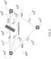
- FIG. 6illustrates one example that includes only one additional anchor B 202".
- a bias ⁇ R ABis present in the total distance traveled by the signal. This bias is present in the measurement of time of flight.
- the distance, or time, bias between two anchors in systems where no line of sight exists between nodescan be estimated offline prior to the BS-TDOA transmissions, or during the BS-TDOA operation by letting the second anchor B 202" transmitting an additional packet. Anchor A 201" can then receive this additional packet, that itself transmitted, and then estimates the round trip delay bias.
- the systems and methods described hereincan effectively compensate the bias in the time of flight estimation in NLOS channels between anchors. With the calculated bias, the estimated time of flight can be significantly reduced and subsequently, the position estimate based on the time-of-flight or time-difference-of-arrival is more accurate.
- anchors in a real time location systemcan be used in buildings or locations where non-line-of-sight conditions exist while maintaining high accuracy of position estimates of mobile devices based on TDOA schemes.
Landscapes
- Engineering & Computer Science (AREA)
- Physics & Mathematics (AREA)
- General Physics & Mathematics (AREA)
- Radar, Positioning & Navigation (AREA)
- Remote Sensing (AREA)
- Computer Networks & Wireless Communication (AREA)
- Signal Processing (AREA)
- Mobile Radio Communication Systems (AREA)
- Position Fixing By Use Of Radio Waves (AREA)
Description
- The present disclosure relates generally to the localization systems and more particularly to methods and systems to locating objects wirelessly using time-of-flight information where there may be no line of sight between objects.
- Time-of-Flight (ToF), also known as Time-of-Arrival (ToA), is often used to measure the distance between two wireless devices. The distance R can be easily calculated as fly timet multiplied by the traveling speed of the signal, i.e.,R=c∗t. For a radio frequency signal,c is approximately 3x10⁸m/s.
- This direct conversion between time and distance is the foundation of many ToF based location estimation technologies. If the ToF is known between a device to be localized (DTBL), referred as mobile device hereinafter, and multiple devices with known locations (referred as anchors, or reference nodes hereinafter), the distances between a mobile device and anchors can be computed and subsequently the mobile location is estimated using multi-lateration, or other techniques. The localization based on ToA has been widely used in many wireless localization systems.
- Given that a mobile node, or device, is generally not time-synchronized to anchors in a given network, a technique called Two-Way TOA (TW-TOA) is commonly used to estimate the location of the mobile device. TW-TOA techniques may require signals to be transmitted and received by both the anchor and the mobile device. By doing so, the round trip fly time is measured and the distance is calculated using the round trip delay as R=c∗T/2, where T is the round trip fly-time. Such an implementation using TW-TOA is bandwidth and energy inefficient because of the large number of transmissions needed for each localization operation. A system using TW-TOA for localization operations often has a significant capacity limit, i.e., the total number of nodes, or updates are very limited.
- A more efficient technique for localization than TW-TOA is based on measuring the Time-Difference-of-Arrival (TDOA). TDOA estimates the differences in the distance from the mobile device to a plurality of different anchors. The differences in distance are calculated by measuring the difference of time when signals arrive at each receiver anchor, which subsequently determines the flight time difference. There are a number of methods to realize TDOA-based locationing, such as downlink TDOA (DL-TDOA), such as the TDOA system described in
U.S. Patent Application Publication No. 2015/0156746 , 'Method and System for Estimating the Location of a Receiving Device', uplink TDOA (UL-TDOA), such as the UL-TDOA system described inUS Patent Application Publication No. 2015/0185309 , 'Method and System for Estimating the Location of a Transmitting Device In a Wireless Network', and Beacon synchronized TDOA (BS-TDOA). The present disclosure describes techniques to improve the performance of the TDOA systems and can be applicable to all TDOA schemes. - A DL-TDOA system is illustrated in
FIGS. 2(a) and 2(b) . At the start of a positioning ranging process, ananchor 2210 can transmit a first request (REQ)packet 2208. One ormore anchors 2202 can respond to theREQ packet 2208 by each transmitting response (RSP)packets 2209. ARSP packet 2209 may only be transmitted by ananchor 2202 after it receives aREQ packet 2208. Amobile device 2103 can receive both the REQ and theRSP packets - A UL-TDOA system is illustrated in
FIG. 7 . The UL-TDOA system can include at least onemobile device 3101 and a plurality ofanchors 3101. At the start of a localization process, a mobile device,M 3103, can transmit aREQ packet 3208. One of the anchors in range, for example anchora0 3101 can responds toREQ packet 3208 by transmitting aRSP packet 3209. Other anchors in range, for example anchors a1 -a3 3101, can each receive bothREQ 3208 andRSP 3209 packets to determine the time differences of arrival. The location of themobile device M 3103 can thus be estimated, as described in greater detail inU.S. Patent Application Publication No. No. 2015/0185309 , 'Method and System for Estimating the Location of a Transmitting Device In a Wireless Network.' - Another scheme using a hybrid TW-ToA and TDOA, referred to herein as Beacon Synchronized TDOA (BS-TDOA) scheme is illustrated in
FIG. 8 . The BS-TDOA system can include at least onemobile device M 4103 and a plurality ofanchors example a0 4104, can transmit aREQ packet 4208. The mobile device, forexample M 4103 can, after receivingREQ packet 4208, transmit a response packet RSP 4209.RSP packet 4209 can be received by allanchors 4101.Anchors 4101 can determine the time differences between when eachRSP packet 209 is received. The location of themobile device 4103 can then be estimated using the arrival time difference, as described in greater detail inU.S. Patent No. 8,259,699 , 'Method and system for target positioning and tracking in cooperative relay networks' . - In all three TDOA schemes described above, two types of packets are transmitted, a request (REQ) packet, and one or more response (RSP) packets. A RSP packet is only transmitted by a device only after it receives a REQ packet. The difference lies in the devices used to transmit these packets and to measure the time difference of the arrivals.
- In DL-TDOA, an REQ is sent by an anchor, and an RSP is sent by another anchor. The time differences of arrival are measured by a mobile.
- In UL-TDOA, an REQ is sent by a mobile, and one, or more RSP packets are sent by anchors. The time differences of arrival are measured by anchors.
- In BS-TDOA, an REQ is sent by an anchor, and an RSP is sent by a mobile. The time differences of arrival are measured by anchors.
- For current ToA and TDOA localization schemes, the accuracy of the location estimate will be affected by the presence of the non-line of sight (NLOS) measurements. In aforementioned cases, the NLOS measurements can introduce a time delay bias between anchor and mobile that is a factor that needs to be mitigated. Additionally, mobile nodes are often moving within an area covered by a system. As mobile devices are moving through a system, it is often not possible to avoid the occurrence of NLOS measurements, though the bias is not always consistent as the mobile device moves into a more favorable location, the bias will disappear. For TDOA systems, the NLOS bias between anchor nodes can additionally have the same effect on accuracy in location determinations. The bias between anchors, however, is persistent as anchors are fixed and thus do not change locations.
- In all three cases described above, the time of flight between anchors is used to estimate the position of mobile devices. Accurate measurements of time of flight is necessary is for obtaining accurate position estimates for the mobile devices.
- The bias caused by NLOS packet transmissions can severely degrade the accuracy of the position estimate of the mobile device. The bias between anchors can be especially harmful as the bias is always present for all the mobile devices. The bias can negatively impact position estimates of all individual mobile devices using the anchors not within the line of sight of each other.
- To avoid the problems associated with non-line-of-sight bias, it is common practice to carefully choose only the anchor pairs that are within Line-of-Sight (LOS) to each other as TDOA pairs. This, however, can sometimes be difficult to realize, especially in complicated indoor environments. Even in systems where it is possible to carefully chose anchor pairs within LOS, it may require increasing the total number of anchors needed for the coverage, or may significantly reduce the overall network efficiency. LOS systems may also require time-consuming, manual pairing, which can indirectly increase the installation complexity and cost.
- Accordingly, a need exists for systems and methods that allow for a reduction in non-line-of-sight signal transmission bias to enhance position estimates for mobile devices.
US 2015/156746 A1 describes a system for estimating the location of a mobile device. The system can include a mobile device having a processor and a receiver, and a network of transceiver devices. The transceiver devices can be paired into multiple transceiver pairs of transceiver devices within communication range. The mobile device and transceivers can transmit a range request (REQ) packet by one transceiver in a pair; receive the REQ packet by another transceiver in the pair; transmit a range response (RSP) packet by the another transceiver; receive REQ packets by the mobile device; and receive RSP packets by the mobile device. The system is configured to estimate the differences of distances from the mobile node to the first and the second transceiver node in pairs; and to determine a location of the mobile device based on the estimated distance differences of devices.- WYLIE M P ET AL: "The non-line of sight problem in mobile location estimation", UNIVERSAL PERSONAL COMMUNICATIONS, 1996. RECORD., 1996 5TH IEEE INTERN ATIONAL CONFERENCE ON CAMBRIDGE, MA, USA 29 SEPT.-2 OCT. 1, NEW YORK, NY, USA,IEEE, US, vol. 2, 29 September 1996, considers the problem of tracking mobile stations using the ranging measurements from multiple base stations (BSs), without apriori knowledge of which BSs (if any) have a direct line of sight (LOS) range measurement.
US 2015/185309 A1 describes a system for locating a mobile device. In one embodiment, the system includes a mobile device having a processor and a receiver, and at least three transceiver devices forming a network of transceiver devices. The mobile device and transceivers can transmit a request (REQ) packet by the mobile device; receive the REQ packet by the at least three transceiver devices; transmit, by a first one of the at least three transceiver devices receiving the REQ packet, a response (RSP) packet; and receive by at least some of the at least three transceiver devices the REQ and the RSP packet. The at least three transceiver devices that receive both the REQ and the RSP packet, the system determines a difference in arrival time between receiving the REQ packet and the RSP packet. The system can determine the location of the mobile device based on determined differences in arrival time.US 2010/177681 A1 describes a method and system to locate a position of a transceiver in a cooperative relay network of nodes. A primary node broadcasts a range request (RREQ) message. A target node, in response to receiving the RREQ message, broadcasts a range reply (RREP) message, wherein the RREP message includes a time difference between receiving the RREQ message and broadcasting the RREP message. A secondary node, in response to receiving the RREQ message and the RREP message, broadcasts a range data (RDAT) message, wherein the RDAT message includes a time difference between receiving the RREQ message and the RREP message. Then, a position solver can determine a location of the target node based on the time differences in the RREP message and the RDAT message.- According to an aspect of the invention, there is provided a method according to
claim 1. - In some embodiments, the estimated non-line of sight bias can be filtered. The locations of the first anchor and the second anchor can be known. The estimated non-line of sight bias can be embedded in a third packet and transmitted by the first anchor.
- In some embodiments the non-line of sight bias between the first and second anchors can be compensated, according to: ΔRAB = tAB∗c- RAB = ΔtA/2∗c - RAB. Here, tAB can be the time of travel of the first packet from the first anchor to the second anchor, ΔtA can be the round trip fly-time between the first anchor and the second anchor, and RAB can be the direct path between the first and second anchors. The estimated non-line of sight bias between anchors can be used directly in estimating a corrected distance difference, according to: ΔRCAB = ΔRMAB - ΔRAB. Where ΔRMAB is the original distance difference measured at the mobile device.
- In other embodiments, the round trip fly-time between the first and second anchor can be embedded in a third packet and transmitted by the first anchor. The locations of one or both of the first and second anchors can be unknown. The non-line of sight bias between the first and second anchors can be estimated and updated a plurality of times. The non-line of sight bias between the first and second anchors can be estimated during the initial setup of the network.
- According to another aspect of the invnetion, there is provided a method according to claim 11.
- In some embodiments the method can include estimating the position of the mobile device using the corrected time differences of arrival. Estimating the position of the mobile device can be done in an external computing device.
- According to a further aspect of the invention, there is provided a method according to
claim 14. - In some embodiments the method can include estimating the position of the mobile device using the corrected time differences of arrival. Estimating the position of the mobile device can be done in an external computing device.
- The following detailed description is provided with the accompanying drawings, in which:
Figure 1 is a prior art schematic of localization network based on a downlink TDOA scheme;Figure 2(a) shows a prior art of a schematic of transmission and reception of wireless signals;Figure 2(b) shows a prior art timing diagram of the transmission and reception of the wireless signals;Figure 3(a) illustrates signal transmissions with NLOS path between anchors in a DL-TDOA scheme;Figure 3(b) illustrates the timing with NLOS path between anchors in a DL-TDOA transmission;Figures 4(a) - (c) are the flow charts illustrating anchors and mobile device for a TDOA location operation;Figure 5 is a schematic of a bias compensation for network based on uplink TDOA scheme;Figure 6 is a schematic of a bias compensation for network based on beacon synchronized TDOA scheme;Figure 7 is a schematic of a prior art UL-TDOA scheme;Figure 8 is a schematic of a prior art BS-TDOA system.- This present disclosure describes systems and methods to automatically estimate the fly-time bias for anchor pairs and compensate for it during the position estimate process. As a result, the system can deploy a TDOA network with anchors installed in arbitrary locations and without having to worry about introducing bias from non-line-of-sight packet transmissions. According to the present disclosure and two anchors within range of each other can be used as a TDOA pair. The present disclosure can significantly simplify the network planning process as it allows the network to be planned manually and at the same time reduces the total number of anchor devices, increases the location coverage, and offers more accurate position services.
FIG. 1 illustrates a prior art Time-of-Flight (TOF) based locationing system 1100 which consists of a number ofanchor devices 1101 andmobile devices 1103. In a DL-TDOA configuration, as described inU.S. Patent Application Publication No. 2015/0156746 , anchor nodes are grouped in pairs (e.g., anchor pairs 1102). Eachpair 1102 consists of twoanchors 1101 that are within each other's range. For example, anchors A and B form apair 1102. Further, anchors A, B, C, and D can additionally be paired into the following pairs {B,D}, {C,D}, {C,A}, {B,C} and {A,D} if those nodes are within each other's range. For TDOA location operation, all, or some of the anchor pairs can transmit using RF signals 1112. Alternatively, the present disclosure contemplates that additional signal types can be used. The RF signals 1112 are received by themobile devices 1103. The reception time of thesignals 1112 are estimated and used to determine the distance difference from the mobile to anchors respectively. With the distance differences, and the anchor locations known, the position of themobile device 1133 can be estimated.- The present application assumes that signals transmitted by radio devices are in the form of packets. Moreover, the anchors, radio nodes, and mobile devices can be Ultra-Wideband (UWB) radio devices. Alternatively, it is understood that other signal formats can be used as long as timing information can be extracted. The mobile devices, anchors, and other nodes can be formed together as a single network.
- During a downlink TDOA (DL-TDOA) operation, each
anchor 2201, 2202 in an anchor pair {A, B} can transmit one packet.FIG. 2(a) illustrates twoanchors 2201, 2202 and onemobile device 2103 in the DL-TDOA operation. The first anchor 2201 can transmit anREQ packet 2208. Thesecond anchor 2202 can receive theREQ packet 2208 and then can transmit anRSP packet 2209 immediately, or after a brief delay. A mobile node, or mobile device, 2103 can receive both theREQ packet 2208 and theRSP packet 2209. The mobile node can then measure the time delay between the reception of REQ (tMREQ) and RSP (tMRSP), Δt = tMRSP - tMREQ. - The time-of-flight of the signals are illustrated in
FIGS. 2(a) and 2(b) . TheREQ packet 2208 travels bydistance R AM 2213 to reach amobile device 2103. TheREQ packet 2208 additionally travels bydistance R AB 2212 to reachanchor B 2202. Upon receivingREQ packet 2208,anchor B 2202 transmits apacket RSP 2209. The transmittedsignal RSP 2209 travels bydistance R BM 2223 to reach themobile device 2103. The path from anchor A 2201 tomobile M 2103 is defined as the 'direct path', and the path from anchor A 2201 tomobile M 2103 via a second anchor 2202 (e.g., anchor B) as the 'indirect path'. The distance difference between the direct path and indirect path is ΔR=(RAB+RBM)-RAM. The distance difference from themobile device 2103 to different anchors, e.g., ΔRMAB = RBM-RAM, can be used to estimate the position of the mobile device. The distance difference is estimated as follows:
REQ 2208 to the reception ofRSP 2209 measured by the mobiledevice node M 2103; RAB, and Δt can be computed based on the known locations of anchor A and B. In case the turnaround time at thesecond anchor device 2202 is non-zero, it is subtracted from the measured time difference as well. FIG. 2(b) shows the timing diagram of the packets. Where tAM is the fly-time of signal from anchor A 2201 tomobile device M 2103 directly (A → M), and where tAB, tBM are the fly-times of the signals via the indirect path (A → B → M). Again for simplicity, the turnaround time is assumed to be zero.- Equation (1) can be used to accurately estimate the distance difference ΔRMAB. However, as shown in
FIG. 3(a) a bias can be present in the location estimate when theanchors LOS path R AB 112 betweenanchor A 201 andanchor B 202 is not available, the signal may reachanchor B 202 via a non-line-of-sight (NLOS) path. As shown inFIG. 3 , the NLOS path consists of twosegments R AC 311 andR BC 312 between anchors and areflector 333 due to the presence of aphysical obstacle 300.Obstacle 300 can be, for example, any of a wall, a display, goods, etc. The total travel distance of the signal is greater than the direct LOS path, i.e., RAC+RBC > RAB. As a result, the overall travel from the indirect path has a positive bias ΔRAB = RAC+RBC - RAB. This is reflected as a positive bias in the measured time difference of arrival (TDOA). - In the above discussed NLOS situation, if equation (1) is used directly, this bias ΔRAB will be included in the overall time difference measurement Δt, and as a result, the position estimate can be significantly degraded. Estimating the bias ΔRAB and compensating for it can therefore improve the position estimate accuracy.
FIG. 3(b) shows the timing diagram of the packet transmission and reception at theanchors mobile device 103.FIG. 3(b) additionally illustrates how to estimate the bias ΔRAB. For example, the sequence of packet transmissions is unchanged, i.e., thefirst anchor A 201 transmits aREQ packet 208, thesecond anchor 202 receives thefirst REQ packet 208. The second anchor then transmits aRSP packet 209. Themobile device 103 receives theREQ packet 208, fromanchor A 201, and theRSP packet 209, fromanchor B 202. Themobile device 103 can then measure the difference between the direct path, and the indirect path via thesecond anchor 202.- To estimate the bias, the
first anchor 201 measures the time elapsed between the transmission of the REQ packet to the reception of the RSP packet. Thefirst anchor 201 can estimate the round trip fly-time of the signal via the NLOS path, as ΔtA = 2∗ tAB. The fly-time fromanchor A 201 to anchorB 202 is tAB =ΔtA/2. The distance bias is then computed as
- Once the estimated bias ΔRAB is calculated,
anchor A 201 can broadcast this information. The estimated bias can be embedded into the following REQ packet sent by theanchor A 201. Assuming that anchors 201, 202 are stationary and their locations do not change over time, the bias between an anchor pair does not change. Theanchors anchor RSP packets - The mobile node, after receiving the bias ΔRAB, corrects the original TDOA measurement with the bias, as follows

- As we can see, ΔRCAB = ΔRMAB - ΔRAB = Δt∗c - (RAB +ΔRAB). Equation (3) can be rewritten as

- Equation (4) expresses the relationship that the distance difference can be estimated using the measured time difference of arrival at a mobile device, and the measured flight time between anchors. It is not necessary to know the anchor locations to solve for the distance difference.
FIGS. 4(a)-4(c) illustrate flow diagrams describing the DL-TDOA scheme from the first anchor (initiating anchor), the second anchor (responding anchor) and the mobile device. The flow for each of the nodes, e.g. anchor A, anchor B, and the mobile device, can be summarized as follows:- Initiating anchor (anchor A)
- ∘ transmits
REQ packet 402, - ∘ receives
RSP packet 404, - ∘ estimates the round trip delay ΔtA and computes the
distance bias ΔR AB 406, - ∘ processing the
bias estimate 408, and - ∘ broadcasts the bias (e.g., in the following REQ packet) 410.
- ∘ transmits
- Responding anchor (anchor B)
- ∘ receives
REQ packet 412 and - ∘ transmits
RSP packet 414.
- ∘ receives
- Mobile node (mobile device)
- ∘ receives REQ and
RSP packets 416, - ∘ receives anchor bias ΔR or fly-
time Δt A 418, - ∘ measures fly-time difference Δt between the direct path and
indirect path 420, - ∘ correct the estimated fly-time difference with the
anchor bias ΔR 422, and - ∘ estimates position using corrected distance differences for multiple anchor pairs 424.
- ∘ receives REQ and
- The above described methods are applicable for other TDOA schemes. Except as described below, or as will be readily appreciated by one having ordinary skill in the art, the anchors 201', 202', the mobile device 103', and the physical obstacle 300' are substantially similar to the
anchors mobile device 103, and thephysical obstacle 300 described above. A detailed description of the structure and function thereof is thus omitted here for the sake of brevity. For example, in the case of UL-TDOA, a mobile device 103' can transmit a REQ packet 208' to all anchors within range of the mobile device 103'. One or more of the anchors, e.g. 201', 202', upon receiving the REQ packet 208', can transmit RSP packets 209'. Anchors 201', 202' receive the RSP packets 209'.FIG. 5 illustrates the signal path and packet transmission between the two anchors A and B and a mobile device 103' during the UL-TDOA operation. As shown,mobile device 103 initially transmits a REQ packet 208'; then anchor A 201 receives the REQ packet 208'. Once anchor A 208' receives the REQ packet 208', anchor A 208' can then transmit a RSP packet 209'. Subsequently,anchor B 202 can receive both the REQ andRSP packets FIG. 5 , a physical obstacle 300' between at least anchors A andB 
- The NLOS bias has similar impact on the overall estimate of distance difference as described above. The NLOS bias can be corrected similarly, provided the bias is measured. The anchors 201', 202' can perform the bias measurements prior to the UL-TDOA operation, for example during the initialization of the system. Alternatively, the anchors 201', 202'can perform the bias measurements by transmitting an additional packet from anchor B 202' back to anchor A 201' at any time.
- If the true fly-time between anchors is known, the NLOS bias can be compensated for. To compensate for the NLOS bias, equation (5) can be rewritten as


- In a further alternative system, the above described bias compensation can be applied to BS-TDOA scheme. Except as described below, or as will be readily appreciated by one having ordinary skill in the art, the
anchors 201", 202', themobile device 103", and thephysical obstacle 300" are substantially similar to theanchors mobile device 103, and thephysical obstacle 300 described above. A detailed description of the structure and function thereof is thus omitted here for the sake of brevity. In a BS-TDOA scheme, as shown inFIG. 6 , a first anchor, or beacon, A 201" can transmit aREQ packet 208". Themobile device 103" can receive theREQ packet 208" and in response can transmit aRSP packet 209". Other anchors within range,e.g. anchor B 202", can receive both theREQ packet 208" fromanchor A 201", and theRSP packet 209" from themobile device 103".FIG. 6 illustrates one example that includes only oneadditional anchor B 202". The locations of bothanchors 201", 202" is known, thereforeanchor B 202" can estimate the distance difference between the direct path (A->B) and the indirect path (A→M→B) based on the time difference of arrival measured at anchor B 202'' as Δt,

- If the path between the
anchor A 201" and theanchor B 202" is non-line-of-sight, (NLOS), a bias Δ RAB is present in the total distance traveled by the signal. This bias is present in the measurement of time of flight. - The correction of the NLOS bias can be applied as


- Again, the distance, or time, bias between two anchors in systems where no line of sight exists between nodes can be estimated offline prior to the BS-TDOA transmissions, or during the BS-TDOA operation by letting the
second anchor B 202" transmitting an additional packet.Anchor A 201" can then receive this additional packet, that itself transmitted, and then estimates the round trip delay bias. - The systems and methods described herein can effectively compensate the bias in the time of flight estimation in NLOS channels between anchors. With the calculated bias, the estimated time of flight can be significantly reduced and subsequently, the position estimate based on the time-of-flight or time-difference-of-arrival is more accurate. Using this technology, anchors in a real time location system can be used in buildings or locations where non-line-of-sight conditions exist while maintaining high accuracy of position estimates of mobile devices based on TDOA schemes.
- Although systems and methods have been described by way of examples of preferred embodiments, it is to be understood that various adaptations and modifications may be made within the scope of the claims.


Claims (14)
- A method for compensating for non-line-of-sight "NLOS" bias in time difference of arrival "TDOA" estimate between a first anchor (201) and a second anchor (202) in a network having an obstacle (300) in the line-of-sight therebetween, the method comprising:transmitting (402), by the first anchor, a first packet "REQ packet" (208) from the first anchor;receiving (412) the first packet by the second anchor via a non-line-of-sight path between the first anchor and the second anchor;transmitting (414) a second packet "RSP packet" (209) by the second anchor, responsive to receiving the first packet;receiving (404) the second packet by the first anchor via the non-line-of-sight path between the first anchor and the second anchor;receiving (416, 418) the first packet and the second packet by a mobile device (103);estimating (406), by the first anchor, a round trip fly-time of the first packet and the second packet between the first anchor and the second anchor;estimating (408), by the first anchor, the non-line-of-sight bias in time of flight of one of the first packet or the second packet between the first anchor and the second anchor, based on the estimated round trip fly-time;transmitting (410), by the first anchor, the estimated non-line-of-sight bias to the mobile device;estimating (420), by the mobile device, the time difference of arrival at the mobile device between a direct path and an indirect path, wherein the direct path is the path followed by the first packet sent directly by the first anchor to the mobile device, and wherein the indirect path is the path between the mobile device and the first anchor via the second anchor;using (422), by the mobile device, the estimated non-line-of-sight bias to correct the time difference of arrival estimated at the mobile device to calculate a corrected time difference of arrival; andestimating (424), by at least one of the mobile device or an external computing device, a position of the mobile device based on the corrected time difference of arrival.
- The method of claim 1, wherein the estimated non-line-of-sight bias is filtered.
- The method of claim 1, wherein the locations of the first anchor and the second anchor are known.
- The method of claim 1, wherein the estimated non-line-of-sight bias is embedded in a third packet and transmitted by the first anchor.
- The method of claim 1, wherein the non-line-of-sight bias between the first and second anchors is compensated, according to:
 wherein tAB is the time of travel of the first packet from the first anchor to the second anchor,wherein ΔtA is the round trip fly-time between the first anchor and the second anchor, andwherein RAB is the direct path between the first and second anchors.
 - The method of claim 5, wherein the estimated non-line-of-sight bias between anchors is used directly in estimating a corrected distance difference, according to:

- The method of claim 1, wherein the round trip fly-time between the first and second anchor is embedded in a third packet and transmitted by the first anchor.
- The method of claim 1, wherein the locations of one or both of the first and second anchors are unknown.
- The method of claim 1, wherein the non-line-of-sight bias between the first and second anchors is estimated and updated a plurality of times.
- The method of claim 1, wherein the non-line-of-sight bias between the first and second anchors is estimated during the initial setup of the network.
- A method to compensate for non-line-of-sight "NLOS" bias in a time difference of arrival estimate introduced by an obstacle in a line-of-sight between a first anchor and a second anchor, using an uplink time difference of arrival "UL-TDOA" scheme, the method comprising:transmitting, by a mobile device, a first packet "REQ packet" (208') from the mobile device (103');receiving the first packet by at least one first anchor (201');transmitting a second packet "RSP packet" (209') by the at least one first anchor responsive to receiving the first packet;receiving the first packet and the second packet by at least one second anchor (202') in range of the mobile device and the at least one first anchor;estimating, by the at least one second anchor, a non-line-of-sight bias in time of flight related to transmission of packets between the at least one first anchor and the at least one second anchor where no line of sight exists between the first anchor and the second anchor;estimating, by the at least one second anchor, the time differences of arrival at the at least one second anchor between a direct path and an indirect path, wherein the direct path is the path followed by the first packet received directly by the at least one second anchor from the mobile device, and wherein the indirect path is the path between the mobile device and the at least one second anchor via the at least one first anchor; andusing, by the at least one second anchor, the estimated non-line-of-sight bias to correct the time differences of arrival at the at least one second anchor.
- The method of claim 11 further comprising, estimating the position of the mobile device using the corrected time differences of arrival.
- The method of claim 12, wherein estimating the position of the mobile device is done in an external computing device.
- A method to compensate for the non-line-of-sight "NLOS" bias in a beacon synchronized time difference of arrival "BS-TDOA" estimate introduced by an obstacle in a line-of-sight between a first anchor and a second anchor, the method comprising:transmitting, by a first anchor, a first packet "REQ packet" (208") from the first anchor (201");receiving the first packet by a mobile node (103");transmitting a second packet "RSP packet" (209") by the mobile node, responsive to receiving the first packet;receiving the first packet and the second packet by at least one second anchor (202") that is within range of the first anchor and the mobile node;measuring, by the at least one second anchor, the time differences of arrival between a direct packet transmission path and an indirect packet transmission path by the at least one second anchor, wherein the direct packet transmission path is the path followed by the first packet sent directly by the first anchor to the at least one second anchor, and wherein the indirect packet transmission path is the path between the first anchor and the at least one second anchor via the mobile node;estimating, by the at least one second anchor, a non-line-of-sight bias in time of flight of any packet between the first anchor and the at least one second anchor; andcorrecting, by the at least one second anchor, the time differences of arrival with the estimated NLOS bias of fly-time between the first anchor and at least one second anchor.


Applications Claiming Priority (2)
| Application Number | Priority Date | Filing Date | Title |
|---|---|---|---|
| US201562218070P | 2015-09-14 | 2015-09-14 | |
| PCT/US2016/051633WO2017048779A1 (en) | 2015-09-14 | 2016-09-14 | Method to estimate and compensate for nlos bias in time difference of arrival estimate |
Publications (3)
| Publication Number | Publication Date |
|---|---|
| EP3322998A1 EP3322998A1 (en) | 2018-05-23 |
| EP3322998A4 EP3322998A4 (en) | 2018-12-12 |
| EP3322998B1true EP3322998B1 (en) | 2020-02-26 |
Family
ID=58237289
Family Applications (1)
| Application Number | Title | Priority Date | Filing Date |
|---|---|---|---|
| EP16847185.2AActiveEP3322998B1 (en) | 2015-09-14 | 2016-09-14 | Method to estimate and compensate for nlos bias in time difference of arrival estimate |
Country Status (4)
| Country | Link |
|---|---|
| US (2) | US10200886B2 (en) |
| EP (1) | EP3322998B1 (en) |
| CN (1) | CN107923964B (en) |
| WO (1) | WO2017048779A1 (en) |
Families Citing this family (45)
| Publication number | Priority date | Publication date | Assignee | Title |
|---|---|---|---|---|
| US9037094B2 (en) | 2011-10-17 | 2015-05-19 | Golba Llc | Method and system for high-throughput and low-power communication links in a distributed transceiver network |
| US9197982B2 (en) | 2012-08-08 | 2015-11-24 | Golba Llc | Method and system for distributed transceivers for distributed access points connectivity |
| US10455350B2 (en) | 2016-07-10 | 2019-10-22 | ZaiNar, Inc. | Method and system for radiolocation asset tracking via a mesh network |
| CN107105405B (en)* | 2017-03-31 | 2018-08-24 | 四川中电昆辰科技有限公司 | The method for correcting position error |
| US10321332B2 (en) | 2017-05-30 | 2019-06-11 | Movandi Corporation | Non-line-of-sight (NLOS) coverage for millimeter wave communication |
| US10484078B2 (en) | 2017-07-11 | 2019-11-19 | Movandi Corporation | Reconfigurable and modular active repeater device |
| TWI645726B (en) | 2017-11-22 | 2018-12-21 | 中磊電子股份有限公司 | Transceiving apparatus and controlling method thereof for spectrum access |
| US10348371B2 (en) | 2017-12-07 | 2019-07-09 | Movandi Corporation | Optimized multi-beam antenna array network with an extended radio frequency range |
| US10090887B1 (en) | 2017-12-08 | 2018-10-02 | Movandi Corporation | Controlled power transmission in radio frequency (RF) device network |
| US10862559B2 (en) | 2017-12-08 | 2020-12-08 | Movandi Corporation | Signal cancellation in radio frequency (RF) device network |
| CN108107421A (en)* | 2017-12-26 | 2018-06-01 | 北京锐安科技有限公司 | A kind of interior distance measuring method and device |
| US11762056B2 (en) | 2018-01-12 | 2023-09-19 | Red Point Positioning Corporation | Method and apparatus for determining location of an object |
| CN108398706B (en)* | 2018-01-23 | 2019-11-08 | 上海工程技术大学 | A cruise dispatch management system and method thereof |
| CN108267764B (en)* | 2018-01-23 | 2019-11-12 | 上海工程技术大学 | A positioning system and method for a cruise ship at sea |
| CN108333558B (en)* | 2018-02-07 | 2021-11-16 | 南京邮电大学 | Method for rapidly measuring Tof and Tdoa in indoor positioning system |
| CN108235427B (en)* | 2018-02-07 | 2020-12-15 | 南京邮电大学 | A method to measure Tof and Tdoa |
| US11088457B2 (en) | 2018-02-26 | 2021-08-10 | Silicon Valley Bank | Waveguide antenna element based beam forming phased array antenna system for millimeter wave communication |
| US10637159B2 (en) | 2018-02-26 | 2020-04-28 | Movandi Corporation | Waveguide antenna element-based beam forming phased array antenna system for millimeter wave communication |
| CN110622024A (en)* | 2018-03-02 | 2019-12-27 | 深圳市汇顶科技股份有限公司 | Indoor positioning method, device and equipment |
| US11483691B2 (en)* | 2018-03-13 | 2022-10-25 | Cypress Semiconductor Corporation | Time of arrival estimation for Bluetooth systems and devices |
| CN110730413A (en)* | 2018-06-29 | 2020-01-24 | 阿里巴巴集团控股有限公司 | Terminal positioning method and device |
| CN113167855B (en)* | 2018-12-19 | 2024-06-18 | 瑞典爱立信有限公司 | Differential matching and positioning |
| US10802104B2 (en)* | 2018-12-26 | 2020-10-13 | Locix, Inc. | Systems and methods for using ranging and triangulation to determine locations of wireless sensor nodes based on radio frequency communications between the nodes and various RF-enabled devices |
| CN111417188B (en)* | 2019-01-04 | 2023-02-21 | 中兴通讯股份有限公司 | Terminal positioning method and device and storage medium |
| CN109799479B (en)* | 2019-03-06 | 2020-12-08 | 珠海格力电器股份有限公司 | Clock positioning method, device, storage medium and communication system |
| CN110167135B (en)* | 2019-04-23 | 2021-07-06 | 重庆邮电大学 | A clock-free TDOA wireless positioning method and system |
| CN110221244B (en)* | 2019-05-24 | 2022-04-19 | 宁波大学 | Robust positioning method based on arrival time difference under non-line-of-sight condition |
| CN110221245B (en)* | 2019-05-28 | 2022-04-19 | 宁波大学 | Robust TDOA localization method for joint estimation of target position and non-line-of-sight error |
| CN110926461B (en)* | 2019-10-29 | 2022-04-12 | 北京全路通信信号研究设计院集团有限公司 | Indoor positioning method and system based on ultra wide band and navigation method and system |
| CN110888111B (en)* | 2019-11-08 | 2021-08-03 | 宁波大学 | Robust non-line-of-sight target self-localization method based on TOA in asynchronous network |
| GB2588966A (en)* | 2019-11-16 | 2021-05-19 | Unipart Group Ltd | Time difference of arrival calculation |
| US12245184B2 (en) | 2019-12-12 | 2025-03-04 | Nokia Technologies Oy | User equipment (UE)-based positioning non-line of sight (NLOS) error mitigation |
| WO2021194904A1 (en) | 2020-03-22 | 2021-09-30 | Frederick Mobile Instrumentation, Llc | Dock area control system |
| EP3975631B1 (en)* | 2020-09-25 | 2024-10-23 | Nxp B.V. | Method and system for determining the position of at least one node in a communication network |
| CN112714491B (en)* | 2020-12-17 | 2022-04-05 | 北京邮电大学 | A positioning method and device |
| US11982698B2 (en)* | 2020-12-21 | 2024-05-14 | Bae Systems Information And Electronic Systems Integration Inc. | Joint denoising and delay estimation for the extraction of pulse-width of signals in RF interference |
| CN113141651B (en)* | 2021-06-23 | 2021-09-07 | 杭州优智联科技有限公司 | Method, device, equipment and medium for acquiring first-arrival path position in UWB system |
| US12300049B2 (en) | 2021-08-31 | 2025-05-13 | Red Point Positioning Corporation | Wireless, tag-based management of equipment- operator interactions |
| US11638187B2 (en) | 2021-09-27 | 2023-04-25 | Red Point Positioning Corporation | Area handover management in real-time locating system (RTLS) networks |
| US20230422193A1 (en)* | 2022-06-28 | 2023-12-28 | Red Point Positioning Corporation | Method and system to synchronize radio device clusters in a wireless network |
| CN119768701A (en)* | 2022-08-30 | 2025-04-04 | 三星电子株式会社 | Method and apparatus for collaborative positioning using UWB communications |
| US11877233B1 (en) | 2023-03-23 | 2024-01-16 | Link Labs, Inc. | Real-time location system for selectively coordinating operative wireless communications protocols when ranging between supporting nodes |
| US12078713B1 (en) | 2023-03-23 | 2024-09-03 | Link Labs, Inc. | Real-time location system using sequenced wireless communications protocols for scheduling timings of node synchronization and time difference of arrival ranging between nodes |
| US11852713B1 (en) | 2023-03-23 | 2023-12-26 | Link Labs, Inc. | Real-time location system using dual wireless communications protocols in a time difference of arrival framework for ranging between nodes |
| WO2025074743A1 (en)* | 2023-10-04 | 2025-04-10 | ソニーセミコンダクタソリューションズ株式会社 | Positioning system, distance measuring device, and positioning device |
Family Cites Families (18)
| Publication number | Priority date | Publication date | Assignee | Title |
|---|---|---|---|---|
| US5031193A (en)* | 1989-11-13 | 1991-07-09 | Motorola, Inc. | Method and apparatus for diversity reception of time-dispersed signals |
| US5630208A (en)* | 1994-07-19 | 1997-05-13 | Trimble Navigation Limited | Adaptive multipath equalization |
| CN1202688C (en)* | 2001-10-18 | 2005-05-18 | 华为技术有限公司 | Method for estimating position of mobile station by utilizing time for receiving signal and time difference and its equipment |
| US8018383B1 (en)* | 2010-06-08 | 2011-09-13 | Q-Track Corporation | Method and apparatus for determining location using signals-of-opportunity |
| US20140313857A1 (en)* | 2005-05-02 | 2014-10-23 | Bruce Kelley Horton | Acoustic propagation method |
| US7574221B2 (en)* | 2006-08-03 | 2009-08-11 | Ntt Docomo, Inc. | Method for estimating jointly time-of-arrival of signals and terminal location |
| JP4495249B2 (en)* | 2006-08-03 | 2010-06-30 | 株式会社エヌ・ティ・ティ・ドコモ | Weighted least squares positioning method using multipath channel statistics for non-line-of-sight mitigation |
| US8219111B2 (en)* | 2007-09-12 | 2012-07-10 | Ntt Docomo | Method for an improved linear least squares estimation of a mobile terminal's location under LOS and NLOS conditions and using map information |
| US8249622B2 (en)* | 2008-11-26 | 2012-08-21 | Andrew, Llc | System and method for multiple range estimation location |
| US8259699B2 (en) | 2009-01-09 | 2012-09-04 | Mitsubishi Electric Research Laboratories, Inc. | Method and system for target positioning and tracking in cooperative relay networks |
| CN102547570B (en)* | 2012-02-20 | 2016-01-13 | 北京邮电大学 | A kind of pseudorange difference location method and device |
| CN202870292U (en)* | 2012-07-09 | 2013-04-10 | 中国矿业大学(北京) | Distance-constraint-based electromagnetic and ultrasound wave combined positioning system for down holes |
| IL227285A0 (en)* | 2013-07-01 | 2013-12-31 | Rami Goldreich | Mitigation of multipath distortions for tdoa-based geolocation |
| CN103686995B (en)* | 2013-11-26 | 2017-02-22 | 北京邮电大学 | Non-line-of-sight environment positioning method and device |
| US20150156746A1 (en)* | 2013-12-03 | 2015-06-04 | Red Point Positioning Corporation | Method and system to estimate the location of a receiving device |
| US10444321B2 (en) | 2013-12-31 | 2019-10-15 | Red Point Positioning Corporation | Method and system to estimate the location of a mobile device using time difference of arrival in an asynchronous wireless network |
| CN104198992B (en)* | 2014-09-11 | 2016-10-05 | 东南大学 | Acoustic Object Passive Location based on multidiameter delay structure compresses perception |
| CN104502893B (en)* | 2014-12-10 | 2017-05-10 | 北京智谷睿拓技术服务有限公司 | positioning method, positioning device and user equipment |
- 2016
- 2016-09-14EPEP16847185.2Apatent/EP3322998B1/enactiveActive
- 2016-09-14WOPCT/US2016/051633patent/WO2017048779A1/ennot_activeCeased
- 2016-09-14USUS15/264,924patent/US10200886B2/enactiveActive
- 2016-09-14CNCN201680051149.XApatent/CN107923964B/enactiveActive
- 2019
- 2019-02-04USUS16/266,517patent/US20190174332A1/ennot_activeAbandoned
Non-Patent Citations (1)
| Title |
|---|
| None* |
Also Published As
| Publication number | Publication date |
|---|---|
| CN107923964A (en) | 2018-04-17 |
| EP3322998A4 (en) | 2018-12-12 |
| US20170078897A1 (en) | 2017-03-16 |
| US10200886B2 (en) | 2019-02-05 |
| EP3322998A1 (en) | 2018-05-23 |
| WO2017048779A1 (en) | 2017-03-23 |
| US20190174332A1 (en) | 2019-06-06 |
| CN107923964B (en) | 2022-02-25 |
Similar Documents
| Publication | Publication Date | Title |
|---|---|---|
| EP3322998B1 (en) | Method to estimate and compensate for nlos bias in time difference of arrival estimate | |
| US12057918B2 (en) | Non-line-of-sight path detection for user equipment positioning in wireless networks | |
| US10624055B2 (en) | Method for determining location of wireless devices | |
| US11051267B2 (en) | Channel latency determining method, positioning method, and related device | |
| US9277369B2 (en) | Method for determining location of wireless devices | |
| US8588087B2 (en) | Method for positioning mobile devices and apparatus for positioning mobile devices | |
| US8259699B2 (en) | Method and system for target positioning and tracking in cooperative relay networks | |
| US9288625B2 (en) | Method for determining location of wireless devices based on information within messages received from other network devices | |
| US20010044311A1 (en) | Identifying starting time for making time of arrival measurements | |
| EP2360967A1 (en) | A method for communicating in a wireless communication network | |
| US9877149B2 (en) | Assisted passive geo-location of a wireless local area network device | |
| WO2008039144A1 (en) | Method and arrangement for base station location, base station synchronization and mobile station location | |
| KR102287266B1 (en) | Wireless localization ranging method between devieces using cooperation terminal and system thereof | |
| EP4286881A1 (en) | Positioning method and system for compensation of internal propagation delays | |
| GB2359699A (en) | locating a mobile station in a cellular telephone network | |
| US11493594B2 (en) | Method and apparatus for TDOA wireless positioning using destructive interference of multiple anchor nodes | |
| EP3293544B1 (en) | Precise positioning using time of arrival with pseudo-synchronized anchor nodes | |
| EP3993521A1 (en) | An apparatus and method for time synchronization | |
| US12302194B2 (en) | Methods and systems for positioning of wireless devices | |
| EP4209798A1 (en) | Secure location of wireless devices using leo satellite assistance | |
| US20240306121A1 (en) | Architecture, protocol, and signaling flow for sidelink positioning and ranging | |
| WO2025068285A1 (en) | Positioning a ue using a plurality of aerial communication systems | |
| WO2024127355A1 (en) | Methods and apparatus for providing assistance to carrier-phase-based positioning in wireless networks | |
| WO2024184707A1 (en) | Localization of backscatterer using other backscatterer | |
| WO2025146247A1 (en) | Multi-technology positioning measurements |
Legal Events
| Date | Code | Title | Description |
|---|---|---|---|
| STAA | Information on the status of an ep patent application or granted ep patent | Free format text:STATUS: THE INTERNATIONAL PUBLICATION HAS BEEN MADE | |
| PUAI | Public reference made under article 153(3) epc to a published international application that has entered the european phase | Free format text:ORIGINAL CODE: 0009012 | |
| STAA | Information on the status of an ep patent application or granted ep patent | Free format text:STATUS: REQUEST FOR EXAMINATION WAS MADE | |
| 17P | Request for examination filed | Effective date:20180103 | |
| AK | Designated contracting states | Kind code of ref document:A1 Designated state(s):AL AT BE BG CH CY CZ DE DK EE ES FI FR GB GR HR HU IE IS IT LI LT LU LV MC MK MT NL NO PL PT RO RS SE SI SK SM TR | |
| AX | Request for extension of the european patent | Extension state:BA ME | |
| RIN1 | Information on inventor provided before grant (corrected) | Inventor name:PEKHTERYEV, GEORGIY Inventor name:YE, ZHENZHEN Inventor name:ZHAO, YU Inventor name:DUAN, CHUNJIE | |
| A4 | Supplementary search report drawn up and despatched | Effective date:20181114 | |
| RIC1 | Information provided on ipc code assigned before grant | Ipc:H04W 64/00 20090101AFI20181108BHEP Ipc:G01S 5/06 20060101ALI20181108BHEP Ipc:H04W 24/10 20090101ALN20181108BHEP | |
| DAV | Request for validation of the european patent (deleted) | ||
| DAX | Request for extension of the european patent (deleted) | ||
| REG | Reference to a national code | Ref country code:DE Ref legal event code:R079 Ref document number:602016030806 Country of ref document:DE Free format text:PREVIOUS MAIN CLASS: G01S0005220000 Ipc:H04W0064000000 | |
| RIC1 | Information provided on ipc code assigned before grant | Ipc:H04W 64/00 20090101AFI20190902BHEP Ipc:H04W 24/10 20090101ALN20190902BHEP Ipc:G01S 5/06 20060101ALI20190902BHEP | |
| GRAP | Despatch of communication of intention to grant a patent | Free format text:ORIGINAL CODE: EPIDOSNIGR1 | |
| STAA | Information on the status of an ep patent application or granted ep patent | Free format text:STATUS: GRANT OF PATENT IS INTENDED | |
| RIC1 | Information provided on ipc code assigned before grant | Ipc:H04W 24/10 20090101ALN20191001BHEP Ipc:G01S 5/06 20060101ALI20191001BHEP Ipc:H04W 64/00 20090101AFI20191001BHEP | |
| INTG | Intention to grant announced | Effective date:20191021 | |
| RAP1 | Party data changed (applicant data changed or rights of an application transferred) | Owner name:RED POINT POSITIONING CORPORATION | |
| GRAS | Grant fee paid | Free format text:ORIGINAL CODE: EPIDOSNIGR3 | |
| GRAA | (expected) grant | Free format text:ORIGINAL CODE: 0009210 | |
| STAA | Information on the status of an ep patent application or granted ep patent | Free format text:STATUS: THE PATENT HAS BEEN GRANTED | |
| AK | Designated contracting states | Kind code of ref document:B1 Designated state(s):AL AT BE BG CH CY CZ DE DK EE ES FI FR GB GR HR HU IE IS IT LI LT LU LV MC MK MT NL NO PL PT RO RS SE SI SK SM TR | |
| REG | Reference to a national code | Ref country code:GB Ref legal event code:FG4D | |
| REG | Reference to a national code | Ref country code:CH Ref legal event code:EP | |
| REG | Reference to a national code | Ref country code:AT Ref legal event code:REF Ref document number:1239245 Country of ref document:AT Kind code of ref document:T Effective date:20200315 | |
| REG | Reference to a national code | Ref country code:IE Ref legal event code:FG4D | |
| REG | Reference to a national code | Ref country code:DE Ref legal event code:R096 Ref document number:602016030806 Country of ref document:DE | |
| PG25 | Lapsed in a contracting state [announced via postgrant information from national office to epo] | Ref country code:FI Free format text:LAPSE BECAUSE OF FAILURE TO SUBMIT A TRANSLATION OF THE DESCRIPTION OR TO PAY THE FEE WITHIN THE PRESCRIBED TIME-LIMIT Effective date:20200226 Ref country code:RS Free format text:LAPSE BECAUSE OF FAILURE TO SUBMIT A TRANSLATION OF THE DESCRIPTION OR TO PAY THE FEE WITHIN THE PRESCRIBED TIME-LIMIT Effective date:20200226 Ref country code:NO Free format text:LAPSE BECAUSE OF FAILURE TO SUBMIT A TRANSLATION OF THE DESCRIPTION OR TO PAY THE FEE WITHIN THE PRESCRIBED TIME-LIMIT Effective date:20200526 | |
| REG | Reference to a national code | Ref country code:NL Ref legal event code:MP Effective date:20200226 | |
| REG | Reference to a national code | Ref country code:LT Ref legal event code:MG4D | |
| PG25 | Lapsed in a contracting state [announced via postgrant information from national office to epo] | Ref country code:BG Free format text:LAPSE BECAUSE OF FAILURE TO SUBMIT A TRANSLATION OF THE DESCRIPTION OR TO PAY THE FEE WITHIN THE PRESCRIBED TIME-LIMIT Effective date:20200526 Ref country code:IS Free format text:LAPSE BECAUSE OF FAILURE TO SUBMIT A TRANSLATION OF THE DESCRIPTION OR TO PAY THE FEE WITHIN THE PRESCRIBED TIME-LIMIT Effective date:20200626 Ref country code:LV Free format text:LAPSE BECAUSE OF FAILURE TO SUBMIT A TRANSLATION OF THE DESCRIPTION OR TO PAY THE FEE WITHIN THE PRESCRIBED TIME-LIMIT Effective date:20200226 Ref country code:SE Free format text:LAPSE BECAUSE OF FAILURE TO SUBMIT A TRANSLATION OF THE DESCRIPTION OR TO PAY THE FEE WITHIN THE PRESCRIBED TIME-LIMIT Effective date:20200226 Ref country code:HR Free format text:LAPSE BECAUSE OF FAILURE TO SUBMIT A TRANSLATION OF THE DESCRIPTION OR TO PAY THE FEE WITHIN THE PRESCRIBED TIME-LIMIT Effective date:20200226 Ref country code:GR Free format text:LAPSE BECAUSE OF FAILURE TO SUBMIT A TRANSLATION OF THE DESCRIPTION OR TO PAY THE FEE WITHIN THE PRESCRIBED TIME-LIMIT Effective date:20200527 | |
| PG25 | Lapsed in a contracting state [announced via postgrant information from national office to epo] | Ref country code:NL Free format text:LAPSE BECAUSE OF FAILURE TO SUBMIT A TRANSLATION OF THE DESCRIPTION OR TO PAY THE FEE WITHIN THE PRESCRIBED TIME-LIMIT Effective date:20200226 | |
| PG25 | Lapsed in a contracting state [announced via postgrant information from national office to epo] | Ref country code:EE Free format text:LAPSE BECAUSE OF FAILURE TO SUBMIT A TRANSLATION OF THE DESCRIPTION OR TO PAY THE FEE WITHIN THE PRESCRIBED TIME-LIMIT Effective date:20200226 Ref country code:SM Free format text:LAPSE BECAUSE OF FAILURE TO SUBMIT A TRANSLATION OF THE DESCRIPTION OR TO PAY THE FEE WITHIN THE PRESCRIBED TIME-LIMIT Effective date:20200226 Ref country code:DK Free format text:LAPSE BECAUSE OF FAILURE TO SUBMIT A TRANSLATION OF THE DESCRIPTION OR TO PAY THE FEE WITHIN THE PRESCRIBED TIME-LIMIT Effective date:20200226 Ref country code:SK Free format text:LAPSE BECAUSE OF FAILURE TO SUBMIT A TRANSLATION OF THE DESCRIPTION OR TO PAY THE FEE WITHIN THE PRESCRIBED TIME-LIMIT Effective date:20200226 Ref country code:RO Free format text:LAPSE BECAUSE OF FAILURE TO SUBMIT A TRANSLATION OF THE DESCRIPTION OR TO PAY THE FEE WITHIN THE PRESCRIBED TIME-LIMIT Effective date:20200226 Ref country code:LT Free format text:LAPSE BECAUSE OF FAILURE TO SUBMIT A TRANSLATION OF THE DESCRIPTION OR TO PAY THE FEE WITHIN THE PRESCRIBED TIME-LIMIT Effective date:20200226 Ref country code:CZ Free format text:LAPSE BECAUSE OF FAILURE TO SUBMIT A TRANSLATION OF THE DESCRIPTION OR TO PAY THE FEE WITHIN THE PRESCRIBED TIME-LIMIT Effective date:20200226 Ref country code:PT Free format text:LAPSE BECAUSE OF FAILURE TO SUBMIT A TRANSLATION OF THE DESCRIPTION OR TO PAY THE FEE WITHIN THE PRESCRIBED TIME-LIMIT Effective date:20200719 Ref country code:ES Free format text:LAPSE BECAUSE OF FAILURE TO SUBMIT A TRANSLATION OF THE DESCRIPTION OR TO PAY THE FEE WITHIN THE PRESCRIBED TIME-LIMIT Effective date:20200226 | |
| REG | Reference to a national code | Ref country code:AT Ref legal event code:MK05 Ref document number:1239245 Country of ref document:AT Kind code of ref document:T Effective date:20200226 | |
| REG | Reference to a national code | Ref country code:DE Ref legal event code:R097 Ref document number:602016030806 Country of ref document:DE | |
| PLBE | No opposition filed within time limit | Free format text:ORIGINAL CODE: 0009261 | |
| STAA | Information on the status of an ep patent application or granted ep patent | Free format text:STATUS: NO OPPOSITION FILED WITHIN TIME LIMIT | |
| PG25 | Lapsed in a contracting state [announced via postgrant information from national office to epo] | Ref country code:IT Free format text:LAPSE BECAUSE OF FAILURE TO SUBMIT A TRANSLATION OF THE DESCRIPTION OR TO PAY THE FEE WITHIN THE PRESCRIBED TIME-LIMIT Effective date:20200226 Ref country code:AT Free format text:LAPSE BECAUSE OF FAILURE TO SUBMIT A TRANSLATION OF THE DESCRIPTION OR TO PAY THE FEE WITHIN THE PRESCRIBED TIME-LIMIT Effective date:20200226 | |
| 26N | No opposition filed | Effective date:20201127 | |
| PG25 | Lapsed in a contracting state [announced via postgrant information from national office to epo] | Ref country code:SI Free format text:LAPSE BECAUSE OF FAILURE TO SUBMIT A TRANSLATION OF THE DESCRIPTION OR TO PAY THE FEE WITHIN THE PRESCRIBED TIME-LIMIT Effective date:20200226 Ref country code:PL Free format text:LAPSE BECAUSE OF FAILURE TO SUBMIT A TRANSLATION OF THE DESCRIPTION OR TO PAY THE FEE WITHIN THE PRESCRIBED TIME-LIMIT Effective date:20200226 | |
| REG | Reference to a national code | Ref country code:CH Ref legal event code:PL | |
| REG | Reference to a national code | Ref country code:BE Ref legal event code:MM Effective date:20200930 | |
| PG25 | Lapsed in a contracting state [announced via postgrant information from national office to epo] | Ref country code:LU Free format text:LAPSE BECAUSE OF NON-PAYMENT OF DUE FEES Effective date:20200914 | |
| PG25 | Lapsed in a contracting state [announced via postgrant information from national office to epo] | Ref country code:BE Free format text:LAPSE BECAUSE OF NON-PAYMENT OF DUE FEES Effective date:20200930 Ref country code:CH Free format text:LAPSE BECAUSE OF NON-PAYMENT OF DUE FEES Effective date:20200930 Ref country code:IE Free format text:LAPSE BECAUSE OF NON-PAYMENT OF DUE FEES Effective date:20200914 Ref country code:LI Free format text:LAPSE BECAUSE OF NON-PAYMENT OF DUE FEES Effective date:20200930 | |
| PG25 | Lapsed in a contracting state [announced via postgrant information from national office to epo] | Ref country code:TR Free format text:LAPSE BECAUSE OF FAILURE TO SUBMIT A TRANSLATION OF THE DESCRIPTION OR TO PAY THE FEE WITHIN THE PRESCRIBED TIME-LIMIT Effective date:20200226 Ref country code:MT Free format text:LAPSE BECAUSE OF FAILURE TO SUBMIT A TRANSLATION OF THE DESCRIPTION OR TO PAY THE FEE WITHIN THE PRESCRIBED TIME-LIMIT Effective date:20200226 Ref country code:CY Free format text:LAPSE BECAUSE OF FAILURE TO SUBMIT A TRANSLATION OF THE DESCRIPTION OR TO PAY THE FEE WITHIN THE PRESCRIBED TIME-LIMIT Effective date:20200226 | |
| PG25 | Lapsed in a contracting state [announced via postgrant information from national office to epo] | Ref country code:MK Free format text:LAPSE BECAUSE OF FAILURE TO SUBMIT A TRANSLATION OF THE DESCRIPTION OR TO PAY THE FEE WITHIN THE PRESCRIBED TIME-LIMIT Effective date:20200226 Ref country code:MC Free format text:LAPSE BECAUSE OF FAILURE TO SUBMIT A TRANSLATION OF THE DESCRIPTION OR TO PAY THE FEE WITHIN THE PRESCRIBED TIME-LIMIT Effective date:20200226 Ref country code:AL Free format text:LAPSE BECAUSE OF FAILURE TO SUBMIT A TRANSLATION OF THE DESCRIPTION OR TO PAY THE FEE WITHIN THE PRESCRIBED TIME-LIMIT Effective date:20200226 | |
| PGFP | Annual fee paid to national office [announced via postgrant information from national office to epo] | Ref country code:GB Payment date:20220908 Year of fee payment:7 | |
| PGFP | Annual fee paid to national office [announced via postgrant information from national office to epo] | Ref country code:FR Payment date:20220908 Year of fee payment:7 | |
| GBPC | Gb: european patent ceased through non-payment of renewal fee | Effective date:20230914 | |
| PG25 | Lapsed in a contracting state [announced via postgrant information from national office to epo] | Ref country code:GB Free format text:LAPSE BECAUSE OF NON-PAYMENT OF DUE FEES Effective date:20230914 | |
| PG25 | Lapsed in a contracting state [announced via postgrant information from national office to epo] | Ref country code:GB Free format text:LAPSE BECAUSE OF NON-PAYMENT OF DUE FEES Effective date:20230914 Ref country code:FR Free format text:LAPSE BECAUSE OF NON-PAYMENT OF DUE FEES Effective date:20230930 | |
| PGFP | Annual fee paid to national office [announced via postgrant information from national office to epo] | Ref country code:DE Payment date:20240904 Year of fee payment:9 |