EP3321783B1 - Adjustable mouse - Google Patents
Adjustable mouseDownload PDFInfo
- Publication number
- EP3321783B1 EP3321783B1EP17201388.0AEP17201388AEP3321783B1EP 3321783 B1EP3321783 B1EP 3321783B1EP 17201388 AEP17201388 AEP 17201388AEP 3321783 B1EP3321783 B1EP 3321783B1
- Authority
- EP
- European Patent Office
- Prior art keywords
- base
- rest portion
- thumb
- adjustment assembly
- mouse
- Prior art date
- Legal status (The legal status is an assumption and is not a legal conclusion. Google has not performed a legal analysis and makes no representation as to the accuracy of the status listed.)
- Active
Links
Images


Classifications
- G—PHYSICS
- G06—COMPUTING OR CALCULATING; COUNTING
- G06F—ELECTRIC DIGITAL DATA PROCESSING
- G06F3/00—Input arrangements for transferring data to be processed into a form capable of being handled by the computer; Output arrangements for transferring data from processing unit to output unit, e.g. interface arrangements
- G06F3/01—Input arrangements or combined input and output arrangements for interaction between user and computer
- G06F3/03—Arrangements for converting the position or the displacement of a member into a coded form
- G06F3/033—Pointing devices displaced or positioned by the user, e.g. mice, trackballs, pens or joysticks; Accessories therefor
- G06F3/0354—Pointing devices displaced or positioned by the user, e.g. mice, trackballs, pens or joysticks; Accessories therefor with detection of 2D relative movements between the device, or an operating part thereof, and a plane or surface, e.g. 2D mice, trackballs, pens or pucks
- G06F3/03543—Mice or pucks
- G—PHYSICS
- G06—COMPUTING OR CALCULATING; COUNTING
- G06F—ELECTRIC DIGITAL DATA PROCESSING
- G06F2203/00—Indexing scheme relating to G06F3/00 - G06F3/048
- G06F2203/033—Indexing scheme relating to G06F3/033
- G06F2203/0333—Ergonomic shaped mouse for one hand
- G—PHYSICS
- G06—COMPUTING OR CALCULATING; COUNTING
- G06F—ELECTRIC DIGITAL DATA PROCESSING
- G06F2203/00—Indexing scheme relating to G06F3/00 - G06F3/048
- G06F2203/033—Indexing scheme relating to G06F3/033
- G06F2203/0334—Ergonomic shaped mouse for vertical grip, whereby the hand controlling the mouse is resting or gripping it with an attitude almost vertical with respect of the working surface
Definitions
- This disclosurerelates generally to pointing devices, and more specifically to an adjustable mouse that detects two-dimensional motion relative to a surface and enables fine control of a graphical user interface ("GUI").
- GUIgraphical user interface
- a typical mouseincludes two or more buttons and a scroll wheel, which can also act as an additional button to move a pointer in two dimensions on a GUI. It is desirable that the mouse fits comfortably within the user's hand while manipulating the mouse.
- Such ergonomically designed devicescan be found in U.S. Patent Nos. 5,576,733 , 6,072,471 , D461,188 , and D632,691 . However, none of the devices disclosed in these patents can be adjusted to vary the size of the mouse so that the mouse fits more comfortably within different users' hands.
- Embodiments of the inventionsignificantly overcome such deficiencies and provide mechanisms and techniques that provide an adjustable mouse according to claim 1 and comprising a base and a thumb adjustment assembly coupled to the base.
- the thumb adjustment assemblyis configured to move a thumb rest portion between a retracted position and an extended position.
- the thumb adjustment assemblyincludes a telescopic shaft that extends from a body of the thumb rest portion and is secured to the thumb rest portion by a ball joint.
- the telescopic shaftis coupled to the base by a pivot post that extends from the base and is configured to pivot with respect to the base and and to move the thumb rest portion toward and away from the base.
- Dependent claimsdefine preferred embodiments.
- an adjustable mousecomprising a base and a thumb adjustment assembly coupled to the base.
- the thumb adjustment assemblyis configured to move a thumb rest portion between a retracted position and an extended position.
- the thumb adjustment assemblyincludes a first telescopic shaft secured to the thumb rest portion by a universal ball joint, with the first telescopic shaft being supported by the base to move the thumb rest portion toward and away from the base.
- the first telescopic shaftextends from a body of the thumb rest portion.
- the first telescopic shaftis coupled to the base by a pivot post that extends from the base, with the telescopic shaft being configured to pivot with respect to the base and to move the thumb rest portion toward and away from the base.
- the adjustable mousefurther may comprise a palm rest portion hingedly attached to the base by a hinge adjacent an outer edge of the base, with the hinge having sufficient friction to position the palm rest portion at a desired angle in a stable position with respect to the base.
- Embodiments of the adjustable mousefurther may include configuring the palm rest portion with internal curved rails to direct the angle adjustment of the palm rest portion with respect to the base portion.
- Embodiments of the adjustable mousefurther may include a height adjustment assembly coupled to the base.
- the height adjustment assemblyis configured to move a palm rest portion and finger buttons between a neutral position and a raised, tilt position.
- the adjustable mousemay further comprise a base adjustment assembly coupled to the base.
- the base adjustment assemblyis configured to move finger buttons between a neutral position for input control and an extended position for input control.
- aspects of the present disclosureare directed to a mouse that is configured to adjust a palm rest portion, a thumb rest portion, and locations of buttons of the mouse to better accommodate a user's hand.
- the mouse of embodiments of the present disclosureis capable of being adjusted to suit a size of a particular user's hand.
- the mouseis capable of adjusting an angle of a body defining the palm rest portion of the mouse.
- the mouseis adjustable at a base and a bottom of the palm rest portion of the mouse to keep a pivot point low and on an outside of the mouse.
- the palm rest portion and associated input controlspivot on an arc thereby making the mouse more ergonomically efficient for the user.
- the adjustable mouseenables varying angle adjustments that a user can adjust to relieve stress on nerves and muscles that become too used or active when using a fixed angled mouse that was not correctly designed for their hand.
- the adjustable mouseis configured to relieve stress in a position initially found comfortable with the mouse, but is found to be uncomfortable after prolonged use made stress in other areas of the hand with previous adjustments.
- the thumb adjustment assemblyincludes a thumb rest portion and a threaded shaft that extends from the thumb rest portion.
- a gear assemblyis associated with the base, and threadably connected to the threaded shaft to retract and extend the threaded shaft with respect to the base.
- the thumb adjustment assemblyincludes a metal shaft that extends from the thumb rest portion, and a magnetic assembly associated with the base, with the magnetic assembly being configured to releasably secure the metal shaft in a desired position with respect to the base.
- the thumb adjustment assemblyincludes a first telescopic shaft secured to the thumb rest portion by a universal ball joint, with the first telescopic shaft being supported by the base to move the thumb rest portion toward and away from the base.
- a second telescopic shaftmay be provided to move the thumb rest portion frontwards and backwards with respect to the base.
- the thumb adjustment assemblyincludes a ball and socket connector with a long thumb rest portion for different sized thumbs.
- an alternative thumb rest portioncan be a smaller sized thumb rest portion that also has a sliding extension portion to make the thumb rest portion bigger (in addition to a double ball joint) and/or to readjust the positioning of the thumb rest portion.
- the thumb rest portionmay embody two separate pieces which are attached by a hinge or a lever that allows a front piece to move with respect to a back piece, with the back piece being able to tilt up and down, and have the ability to tilt in other varying position.
- the back pieceis allowed to tilt up and down in any of a variety of positions by a ball joint, which can be substituted by a pivoting axis or a lever.
- the back piece of the thumb rest portionmay be secured to an input control portion by a ball joint or the back piece may be secured to the base.
- the front piece of the thumb rest portionmay attach to the back piece by a hinge that allows the front piece to change a curvature of the thumb rest portion itself by bending the front piece back and forth.
- the back pieceis attached to the base by the ball joint with a mechanism that allows telescoping in and out.
- the thumb rest portionincludes a small piece on the thumb rest portion that allows the thumb to hold the mouse better by positioning the thumb rest portion on the grip piece.
- the small pieceis may be detached and a grip piece varying in size and thickness may be placed in its location for better comfort and mobility.
- the grip piececan be placed in various locations on the thumb rest portion for better comfort and mobility instead of one location. The small piece allows for better control of the mouse as you are moving it by allowing the thumb to stretch in and out.
- Another related example useful for understanding the claimed inventionis directed to a mouse having input control buttons that extend forward from the palm rest portion on an arc so that a user's fingers have a pitch (do not have to be straight) and length extension.
- mousemay include a flared surface at an outside bottom of the palm rest portion, an input control portion to keep the outside of the hand off of the surface of movement, a lip at a top of the mouse for carrying, a locking feature to lock a tilt angle of adjustment and to lock an extension of the input control buttons along the arc.
- FIGS. 1-6a related examples useful for understanding the claimed invention are shown of an adjustable mouse, that is generally indicated at 10.
- the mouse 10is configured for a user's right hand. It should be understood that the mouse 10 may be configured for a user's left hand and still fall within the scope of the present disclosure.
- the mouse 10is configured to control the motion of a pointer in two dimensions in a GUI, with the mouse converting the movements of the user's hand into equivalent electronic signals to move the pointer in the traditional manner.
- buttonsare provided on the mouse, which may be "clicked" to perform certain actions by the user.
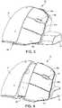
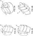
- FIGS. 1 and 2illustrate the mouse 10 having a base 12, an internal frame structure (not shown) secured to the base, and a palm rest portion 14 that is form fitting to the user's hand.
- the mouse 10further includes a thumb adjustment assembly generally indicated at 16 that is configured to move a two-piece thumb rest portion 18 between a retracted position illustrated in FIG. 1 and an extended position illustrated in FIG. 2 .
- the two-piece thumb rest portion 18is connected to the internal frame structure of the base 12 by a ball and socket connector 20, which is configured to extend and retract the thumb rest portion.
- FIGS. 3 and 4illustrate the mouse 10 having a base adjustment assembly, generally indicated at 22, provided adjacent the palm rest portion 14 to adjust a position of finger buttons, illustrated at 24a, 24b and 24c.
- the base adjustment assembly 22may also be referred to as a finger adjustment assembly.
- the base adjustment assembly 22 of mouse 10is designed to extend the finger buttons 24a, 24b and 24c away from the palm rest portion 14 to accommodate operators having larger hands.
- FIG. 3illustrates the base adjustment assembly 22 of the mouse 10 in a neutral position for input control for person's having smaller hands.
- FIG. 4illustrates the base adjustment assembly 22 of the mouse 10 in an extended position for input control for person's having larger hands and/or fingers.
- the finger buttons 24a, 24b and 24care designed to be manipulated by the user's fore, index and ring fingers, respectively, with a wheel 26 provided between the finger buttons 24a, 24b manipulated by the fore and index fingers. It should be understood that although three finger buttons 24a, 24b and 24c are provided for mouse 10, a mouse having less (e.g., two) or more (e.g., four) finger buttons, or without a wheel, may be provided. As shown, the base adjustment assembly 22 extends the finger buttons 24a, 24b and 24c along an arc to conform to the operator's hand.
- FIGS. 5 and 6illustrate the mouse 10 having a height adjustment assembly, generally indicated at 28, to raise the height of the palm rest portion 14 and the finger buttons 24a, 24b and 24c with respect to the base 12 and to tilt the position of these components.
- FIG. 5illustrates the height adjustment assembly 28 of the mouse 10 in a neutral position in which the palm rest portion 14 and the finger buttons 24a, 24b and 24c are disposed adjacent the base 12 of the mouse.
- FIG. 6illustrates the height adjustment assembly 28 of the mouse 10 in a raised, tilt position in which the palm rest portion 14 and the finger buttons 24a, 24b and 24c are raised and tilted with respect to the base 12.
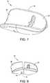
- FIGS. 7-12illustrate the two-piece thumb rest portion 18 of the thumb adjustment assembly 16 having a two separate pieces 30, 32 which are attached by a hinge 34 that allows the front piece 30 to move with respect to the back piece 32, with the back piece being able to tilt up and down to achieve any of a variety of positions.
- the back piece 32is allowed to tilt up and down by the ball and socket connector 20, which can be substituted by a pivoting axis or a lever.
- the back piece 32 of the thumb rest portion 18may be secured to an input control portion by the ball and socket connector 20 or the back piece may be secured to the base 12.
- the front piece 30 of the thumb rest portion 18may attach to the back piece 32 by the hinge 34, which allows the front piece to change a curvature of the thumb rest portion itself by bending the front piece back and forth.
- the back piece 32is attached to the base 12 by the ball and socket connector 20 with a mechanism that allows telescoping in and out.
- the thumb adjustment assembly 16is configured to lock in a desired extended position to lock the thumb rest portion 18 in place.
- the thumb rest portion 18can be locked in place by a dedicated locking mechanism or by friction associated with the mechanism that allows the thumb rest portion to extend in and out.
- the thumb adjustment assembly 16can be further configured to lock the front piece 30 and the back piece 32 in a desired position with respect to each other.
- a small piece of the thumb rest portionallows the thumb to hold the mouse better by positioning the thumb rest portion on the grip piece.
- the small piecemay be detached and a grip piece varying in size and thickness may be placed in its location for better comfort and mobility.
- the grip piececan be placed in various locations on the thumb rest for better comfort and mobility. The small piece allows for better control of the mouse as the mouse is moved by allowing the thumb to stretch in and out.
- FIGS. 9 and 10illustrate the back piece 32 connected to the ball and socket connector 20.
- the ball and socket connector 20includes a head portion 36 that is received within a receptacle 38 formed in the back piece 32 of the thumb adjustment assembly 16.
- the ball and socket connector 20further includes a receptacle 40 that is configured to receive a head portion 42 attached to a stem 44.
- the stem 44is attached a telescoping mechanism associated with the frame structure of the base 12 of the mouse 10 to move the stem, the ball and socket connector 20, and the back piece 32 from the retracted position to extended position.
- the back piece 32is configured to lock in a desired extended position.
- the ball and socket connector 20is configured to inherently lock the back piece 32 of the thumb rest portion 18 when extended to the extended position to lock the thumb rest portion in place.
- the front piece 30may be configured to lock in a similar manner as well. Any number of mechanisms may be included to lock the thumb adjustment assembly 16.
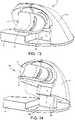
- FIGS. 11 and 12illustrate the construction of the thumb adjustment assembly 16 and the base adjustment assembly 22.
- FIG. 11illustrates the thumb adjustment assembly 16 and the base adjustment assembly 22 in extended positions, with FIG. 12 showing the thumb adjustment assembly 16 disassembled from the base 12 of the mouse 10.
- the base adjustment assembly 22extends the finger buttons 24a, 24b and 24c away from the palm rest portion 14 in a generally arcuate direction with respect to the base 12.
- the base adjustment assembly 22is configured to lock the finger buttons 24a, 24b and 24c in a desired extended position.
- the component parts constituting the base adjustment assembly 22may include interference fit connectors that inherently lock the assembly in a desired position.
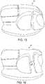
- FIGS. 13 and 14illustrate the construction of the height adjustment assembly 28.
- FIG. 13shows the palm rest portion 14 and the finger buttons 24a, 24b and 24c in a neutral or lowered position.
- FIG. 14shows the palm rest portion 14 and the finger buttons 24a, 24b and 24c in a raised, tilted position.
- the base 12includes a support member 46 on which the palm rest portion 14 and the finger buttons 24a, 24b and 24c are connected.
- the height adjustment assembly 28is configured to lock the palm rest portion 14 and the finger buttons 24a, 24b and 24c in a raised and tilted position with respect to the support member 46.
- the component parts constituting the height adjustment assembly 28, including the support member 46may include interference fit connectors that inherently lock the assembly in a desired position with respect to the support member 46.
- FIGS. 15 and 16illustrate related examples useful for understanding the claimed invention of a mouse, generally indicated at 50, having a thumb adjustment assembly. As shown, the mouse 50 includes a split thumb rest portion adjustment feature.
- the mouse 70is configured for a user's right hand; however, it should be understood that the mouse may be configured for a user's left hand instead.
- the mouse 70is configured to control the motion of a pointer in two dimensions in a GUI, with the mouse converting the movements of the user's hand into equivalent electronic signals to move the pointer in the traditional manner.
- the mouse 70has a base 72 with an integrated palm rest portion that is form fitting to the user's hand.
- the mouse 70further includes a thumb adjustment assembly generally indicated at 74 that is configured to move a thumb rest portion 76 between a retracted position illustrated in FIG.
- the thumb rest portion 76can embody the two-part thumb rest portion described above, and can include a thumb ridge to manipulate the movement of the thumb rest portion.
- the thumb rest portion 76includes a threaded shaft 78 that extends from a body of the thumb rest portion.
- the threaded shaft 78extends through an opening 80 formed in a base cover portion 82 of the base 72, and is threadably connected to a first gear 84.
- a second gear 86which is accessible through another opening 88 formed in the base cover portion 82, meshes with the first gear 84 to drive the movement of the first gear when manipulated by a user's thumb, for example.
- the gear assemblyincludes a gear housing 90 that secures the first and second gear 84, 86 to an inner surface of the base cover portion 82 and the remainder of the base cover.
- FIG. 29Arepresents the thumb rest portion 76 in the retracted position.
- the rotation of the second gear 86 by the user's thumbcauses the rotation of the first gear 84, which in turn rotates the threaded shaft 78 of the thumb rest portion 76 outboard with respect to the base 72.
- This movementcauses the thumb rest portion 76 to achieve the extended portion represented in FIG. 29B .
- the movementis easily achieved by the user by rotating the second gear 86 in a manner similar to the rotation of the scroll wheel described above.
- the mouse 100has a base 102 with an integrated palm rest portion that is form fitting to the user's hand.
- the mouse 100further includes a thumb adjustment assembly generally indicated at 104 that is configured to move a thumb rest portion 106 between a retracted position illustrated in FIG. 31A and an extended position illustrated in FIG. 31B by a magnetic assembly described in greater detail below.
- the thumb rest portion 106includes a metal shaft 108 that extends from a body of the thumb rest portion.
- the metal shaft 108extends through an opening 110 formed in a base cover portion 112 of the base 102, and is received by a magnetic assembly having a magnet housing 114 and two magnets, each indicated at 116, supported by the magnet housing.
- the magnet housing 114 and the magnets 116are held in place on the metal shaft by an e-ring 118 designed to clip onto an end of the metal shaft 108.
- FIG. 31Arepresents the thumb rest portion 106 in the retracted position.
- the movement of the user applied to the thumb rest portion 106can achieve the extended portion represented in FIG. 31B .
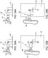
- FIGS. 33A, 33B, 34A and 34Billustrate a related example of a thumb adjustment assembly, useful for understanding the claimed invention, generally indicated at 130.
- the thumb adjustment assembly 130includes a thumb rest portion 132 that is secured to a first telescopic shaft 134 by a universal ball joint 136.
- the first telescopic shaft 134is supported by a base 138, and can be used to position the thumb rest portion 132 in a retracted position FIGS. 33A and 33B ) or in an extended position ( FIGS. 34A and 34B ) away from the base.
- the first telescopic shaft 134can move the thumb rest portion 132 approximately six millimeters (mm).
- the thumb adjustment assembly 130further can include a second telescopic shaft 140 supported by the base 138 to move the thumb rest portion 132 frontwards and backwards.
- FIG. 33Billustrates the thumb rest portion 132 in a rearward position.
- FIG. 34Billustrates the thumb rest portion 132 in a forward position.
- the second telescopic shaft 140can move the thumb rest portion approximately seven mm.
- the first telescopic shaft 134 and the second telescopic shaft 140can be manipulated to change an angle of the thumb rest portion 132 with respect to the base 138 to accommodate the user's hand.
- FIGS. 35A, 35B, 36A and 36Billustrate an embodiment of the thumb adjustment assembly, generally indicated at 1300, which is constructed similarly to the thumb adjustment assembly 130 shown in FIGS. 33A, 33B, 34A and 34B .
- the thumb adjustment assembly 1300includes a thumb rest portion 1320 that is secured to a telescopic shaft 1340 by a universal ball joint 1360.
- the telescopic shaft 1340is supported by a base 1380, and can be used to position the thumb rest portion 1320 in a retracted position FIGS. 35A and 35B ) or in an extended position ( FIGS. 36A and 36B ) away from the base.
- the telescopic shaft 1340can move the thumb rest portion 1320 approximately six millimeters (mm).
- the telescopic shaft 1340is pivotally connected to the base 1380 by a pivot post 1400.
- the pivot post 1400extends vertically from the base.
- FIG. 35Billustrates the thumb rest portion 1320 in a position in which the telescopic shaft 1340 extends from the pivot post 1400 in a direction generally normal or perpendicular to the direction of the base 1380.
- FIG. 36Billustrates the thumb rest portion 1320 in a forward press position in which the telescopic shaft 1340 extends from the pivot post 1400 in a forward pivoted direction.
- the telescopic shaft 1340can be manipulated to change an angle of the thumb rest portion 1320 with respect to the base 1380 to accommodate the user's hand.
- thumb adjustment assembly 1300is efficient and easier to manufacture (less complex than other embodiments), durable in use, and embodies a manageable amount of components, e.g., the thumb rest portion 1320, shaft 1340, ball joint 1360 and pivot post 1400. Additional objects and advantages of this embodiment of the thumb adjustment assembly include that he thumb adjustment assembly 1300 provides a simple but effective hold and positioning of the thumb rest position by friction fit of the components, is user friendly, is intuitive to use and can be used and adjusted on the fly.
- a single ball jointcan be used for simplicity to allow a user to move the thumb rest portion in an ergonomically comfortable position.
- a single ball jointcan achieve the desired result of a double ball joint with respect to extending the thumb rest portion.
- the added benefit of the double ball jointis allowing the thumb rest portion to be fixed in a position while allowing the thumb rest portion to move up or down. This is possible because of the rod connecting the first and the second ball joint creates another arm that an angle of the respective portions.
- a double ball jointcan further be used to enable the thumb rest portion to be moved clockwise, counterclockwise, and tilt in multiple directions.
- the thumb adjustment assemblymay be used to move the thumb rest portion toward or away from the adjustable mouse body thereby accommodating the particular characteristics of the user's hand.
- the embodiments disclosed hereinare designed to allow a user's hand to expand by allowing the thumb to be moved farther away from the remainder of the hand. This relieves cramping and/or pain associated with mice that are too small for the users' hands.
- the thumb adjustment assemblyenables the user to position the thumb rest portion at a desired position away from the base of the adjustable mouse.
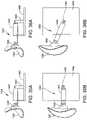
- an adjustable mouseis generally indicated at 150.
- the adjustable mouse 150includes a base portion 152 and a palm rest portion 154 hingedly attached to the base portion by a hinge 156 at an outer edge of the base portion.
- the hinge 150has sufficient friction to position the palm rest portion 154 at a desired angle with respect to the base portion 152 in a stable position.
- the hinge 156is a piano-type hinge, which can also be referred to as a long hinge. The user can select a desired angle by pivoting the palm rest portion 154 with respect to the base portion 152, allowing the friction of the hinge 156 to maintain the palm rest portion in the desired position.
- the construction of the palm rest portionmay embody any of the designs of the palm rest portions disclosed herein.
- FIGS. 38A, 38B and 38Cillustrate an adjustable mouse, generally indicated at 160, which is similarly constructed as adjustable mouse 150.
- the adjustable mouse 160includes a base portion 162 and a palm rest portion 164 hingedly attached to the base portion by a hinge 166 positioned inwardly from an outer edge 168 of the base portion.
- the palm rest portion 164includes internal curved rails 170 to guide the hinge 166 and to direct the angle adjustment of the palm rest portion with respect to the base portion 162.
- the hinge 166has sufficient friction to position the palm rest portion at a desired angle in a stable position. The user can select a desired angle by pivoting the palm rest portion 164 with respect to the base portion 162, allowing the friction of the hinge 166 to maintain the palm rest portion in the desired position.
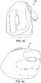
- an adjustable mouse in some embodimentsis generally indicated at 180.
- the adjustable mouse 180includes a base portion 182 and a palm rest portion 184 having a thumb rest portion 186 and finger portions, each indicated at 188.
- the palm rest portion 184is hingedly connected to the base portion 182 by a hinge 190 at an outer edge of the base portion.
- the palm rest portion 184can be angled or tilted with respect to the base portion 182 by one of three wedges 192, 194, 196 illustrated in FIG. 39 .
- the wedges 192, 194, 196can be used to vary an angle or tilt of the palm rest portion with respect to the base portion of the adjustable mouse, e.g., a 10-degree, 20-degree or 30-degree angle with respect to a vertical axis.
- an adjustable mouse in some embodimentsis generally indicated at 200, which is similar to the adjustable mouse 60 shown in FIGS. 17-26 .
- the adjustable mouse 200includes a palm rest portion 202 and a thumb rest portion 204.
- the palm rest portion 202includes a two-part palm engagement portion 206 and three finger portions 208, 210, 212.
- the finger portions 208, 210, 212are configured to expand to enable a user's cramped hand to expand vertically and to extend the finger tips horizontally to relieve discomfort.
- the expansion of the finger portions 208, 210, 212can be achieved by any suitable structure, such as rods attached to individual buttons to the base of the adjustable mouse 200.
- the rodscan be connected to a ball joint or similar mechanism that enables easy manipulation of the fingers 208, 210, 212 of the adjustable mouse.
- the expansion of the finger portions 208, 210, 212further can be achieved by the mechanisms used to extend the thumb adjustment assembly and the base adjustment assembly shown in FIGS. 11 and 12 .
- the ball jointscan be friction-based or a magnet can be placed underneath or inside an input control area to magnetize and maintain the buttons in place.
- a lock and pin mechanismcan be used to lock each button in place, or a rail system can be used to set a plane of travel.
- the tilting angle adjustment mechanisms of the palm rest portion with respect to the base portionare used to reposition the palm rest portion of the adjustable mouse towards either a vertical oriented placement or towards a more horizontal oriented placement.
- the hingeis maintained in place by friction associated with the hinge; however the hinge can be locked in place by using a lock and pin arrangement, a brake pad, a lever, a button, or the like.
- a screw or knobcan be used to move gears that would allow the angle of the palm rest portion to be tilted with respect to the base portion. The screw or knob can be used to tighten or loosen the palm rest portion with respect to the base portion.
- the tilting angle adjustment mechanisms disclosed hereinallow a user to find a comfortable position for his or her hand in relation to the surface of a desk.
- the usercan reposition to tilt angle to a new angle even when the user is used to a certain position.
- This functionality of the adjustable mousehelps reduce stress and tension on one area of the hand, and reduces the probability of causing a problem from over using a certain portion or applying constant pressure on a user's hand.
- FIGS. 41-47illustrate a mouse, generally indicated at 210, of some embodiments of the present disclosure. As shown, the mouse includes a thumb adjustment assembly and a base adjustment assembly.
- the extension of the component parts of the adjustable mousecan be achieved by having the finger and palm rest connected in one or more locations. This can be achieved by using a rod either connected to either the input controls and/or the palm extension fixed in position by a hollow cavity surrounding one or more rods that will direct the one or more rods in a set plane of motion.
- the one or more rodsdo not necessarily need to be cylindrical in shape, but must be held in a hollow cavity to allow a set plane of motion to be achieved.
- a rail system, gears, motor, divots, or even magnetscan be used to move the input controls and the palm extension while locking them into place.
- the palm extensioncan also be configured to move upwards instead of extending towards the back.
- Some embodimentscan include a microprocessor having sensors that are positioned inside the mouse that read the different adjustments and show them on a screen or saved to a personalized account.
- the microprocessorenables users to reposition the device to a preferred setting when the adjustable mouse is used by someone else. If saved to an account or in a general setting file, the microprocessor can also maintain DPI measurements, driver settings, and other information related to the use of the adjustable mouse.
- Other sensorscan be provided inside the mouse to measure user activity, gauge light, and the like. Buttons positioned near a bottom of the mouse can be used to change commands of the buttons, such as disabling the right mouse click or altering a command of the right mouse button. A separate button can be added instead of using the same button as a DPI adjuster button.
Landscapes
- Engineering & Computer Science (AREA)
- General Engineering & Computer Science (AREA)
- Theoretical Computer Science (AREA)
- Human Computer Interaction (AREA)
- Physics & Mathematics (AREA)
- General Physics & Mathematics (AREA)
- Position Input By Displaying (AREA)
- Steroid Compounds (AREA)
- Control Of Throttle Valves Provided In The Intake System Or In The Exhaust System (AREA)
Description
- This disclosure relates generally to pointing devices, and more specifically to an adjustable mouse that detects two-dimensional motion relative to a surface and enables fine control of a graphical user interface ("GUI").
- A typical mouse includes two or more buttons and a scroll wheel, which can also act as an additional button to move a pointer in two dimensions on a GUI. It is desirable that the mouse fits comfortably within the user's hand while manipulating the mouse. Such ergonomically designed devices can be found in
U.S. Patent Nos. 5,576,733 ,6,072,471 ,D461,188 , andD632,691 . However, none of the devices disclosed in these patents can be adjusted to vary the size of the mouse so that the mouse fits more comfortably within different users' hands. - Another prior art mouse is shown in the
PCT application WO 2016/086854 , describing an adjustable mouse. - Conventional mechanisms such as those explained above suffer from a variety of deficiencies. Embodiments of the invention significantly overcome such deficiencies and provide mechanisms and techniques that provide an adjustable mouse according to claim 1 and comprising a base and a thumb adjustment assembly coupled to the base. The thumb adjustment assembly is configured to move a thumb rest portion between a retracted position and an extended position. The thumb adjustment assembly includes a telescopic shaft that extends from a body of the thumb rest portion and is secured to the thumb rest portion by a ball joint. The telescopic shaft is coupled to the base by a pivot post that extends from the base and is configured to pivot with respect to the base and and to move the thumb rest portion toward and away from the base. Dependent claims define preferred embodiments.
- Note that each of the different features, techniques, configurations, etc. discussed in this disclosure can be executed independently or in combination. Accordingly, the present invention can be embodied and viewed in many different ways. Also, note that this summary section herein does not specify every embodiment and/or incrementally novel aspect of the present disclosure or claimed invention. Instead, this summary only provides a preliminary discussion of different embodiments and corresponding points of novelty over conventional techniques. For additional details, elements, and/or possible perspectives (permutations) of the invention, the reader is directed to the Detailed Description section and corresponding figures of the present disclosure as further discussed below.
- According to aspects of this disclosure, an adjustable mouse comprising a base and a thumb adjustment assembly coupled to the base is provided. The thumb adjustment assembly is configured to move a thumb rest portion between a retracted position and an extended position.
- The thumb adjustment assembly includes a first telescopic shaft secured to the thumb rest portion by a universal ball joint, with the first telescopic shaft being supported by the base to move the thumb rest portion toward and away from the base. The first telescopic shaft extends from a body of the thumb rest portion. The first telescopic shaft is coupled to the base by a pivot post that extends from the base, with the telescopic shaft being configured to pivot with respect to the base and to move the thumb rest portion toward and away from the base.
- The adjustable mouse further may comprise a palm rest portion hingedly attached to the base by a hinge adjacent an outer edge of the base, with the hinge having sufficient friction to position the palm rest portion at a desired angle in a stable position with respect to the base.
- Embodiments of the adjustable mouse further may include configuring the palm rest portion with internal curved rails to direct the angle adjustment of the palm rest portion with respect to the base portion.
- Embodiments of the adjustable mouse further may include a height adjustment assembly coupled to the base. The height adjustment assembly is configured to move a palm rest portion and finger buttons between a neutral position and a raised, tilt position.
- The adjustable mouse may further comprise a base adjustment assembly coupled to the base. The base adjustment assembly is configured to move finger buttons between a neutral position for input control and an extended position for input control.
- The foregoing will be apparent from the following more particular description of preferred embodiments of the invention, as illustrated in the accompanying drawings in which like reference characters refer to the same parts throughout the different views. The drawings are not necessarily to scale, emphasis instead being placed upon illustrating the principles of the invention.
FIG. 1 is a perspective view of an adjustable mouse of an embodiment of the present disclosure, with a thumb adjustment assembly in a retracted position;FIG. 2 is a perspective view of the mouse, with the thumb adjustment assembly in an extended position;FIG. 3 is a perspective view of the mouse, with a base adjustment assembly in a neutral position for input control;FIG. 4 is a perspective view of the mouse, with the base adjustment assembly in an extended position for input control;FIG. 5 is a perspective view of the mouse, with a height adjustment assembly in a neutral position;FIG. 6 is a perspective view of the mouse, with the height adjustment assembly in a raised, tilt position;FIG. 7 is a perspective view of a two-piece portion of the thumb adjustment assembly of a related example useful for understanding the claimed invention;FIG. 8 is a perspective view of the two-piece portion of the thumb adjustment assembly shown inFIG. 7 pivoting about a hinge;FIG. 9 is a perspective view of a ball and socket connector secured to the two-piece portion of the thumb adjustment mechanism of a related example useful for understanding the claimed invention;FIG. 10 is an exploded perspective view of the two-piece portion and the ball and socket connector of a related example useful for understanding the claimed invention;FIG. 11 is a top plan view of the mouse showing aspects of the two-piece portion and the ball and socket connector of the thumb adjustment assembly of a related example useful for understanding the claimed invention;FIG. 12 is an exploded top plan view of the mouse showing aspects of the two-piece portion and the ball and socket connector of the thumb adjustment assembly of a related example useful for understanding the claimed invention;FIG. 13 is a perspective view of the mouse showing the height adjustment assembly in the neutral position;FIG. 14 is a perspective view of the mouse showing the height adjustment assembly in the raised, tilt position;FIGS. 15 and 16 are perspective views of a model of an adjustable mouse of a related example useful for understanding the claimed invention;FIGS. 17-26 are perspective views of an adjustable mouse of related examples useful for understanding the claimed invention;FIGS. 27A and 27B are related examples useful for understanding the claimed invention, showing top plan views of an adjustable mouse , with a thumb adjustment assembly in a retracted position (FIG. 27A ) and an extended position (FIG. 27B );FIG. 28 is an exploded perspective view of the thumb adjustment assembly shown inFIGS. 27A and 27B ;FIGS. 29A and 29B are perspective views with portions removed showing the thumb adjustment assembly in the retracted position (FIG. 29A ) and the extended position (FIG. 29B );FIG. 30 is a perspective view of an adjustable mouse of a related example useful for understanding the claimed invention;FIGS. 31A and 31B are perspective views with portions removed of the mouse shown inFIG. 30 showing a thumb adjustment assembly of a related example useful for understanding the claimed invention in a retracted position (FIG. 31A ) and an extended position (FIG. 31B );FIG. 32 is an exploded perspective view of the thumb adjustment assembly of a related example useful for understanding the claimed invention;FIGS. 33A and 33B are side and top schematic views of a thumb adjustment assembly of a related example useful for understanding the claimed invention and showing the thumb adjustment assembly in a retracted position;FIGS. 34A and 34B are side and top schematic views of the thumb adjustment assembly shown inFIGS 33A and 33B showing the thumb adjustment assembly in an extended position;FIGS. 35A and 35B are side and top schematic views of a thumb adjustment assembly of an embodiment of the invention showing the thumb adjustment assembly in a retracted position;FIGS. 36A and 36B are side and top schematic views of the thumb adjustment assembly shown inFIGS 35A and 35B showing the thumb adjustment assembly in an extended position;FIGS. 37A, 37B and 37C are schematic views of an adjustable mouse of an embodiment showing an angle adjustment assembly to adjust a palm rest of the adjustable mouse;FIGS. 38A, 38B and 38C are schematic views of an adjustable mouse of an embodiment showing an angle adjustment assembly to adjust a palm rest of the mouse;FIG. 39 is a perspective view of an adjustable mouse of an embodiment of the present disclosure showing wedge portions used to adjust an angle of a palm rest portion of the adjustable mouse;FIGS. 40A, 40B and 40C are perspective views of an adjustable mouse of an embodiment of the present disclosure showing finger extensions in a retracted position (FIG. 40A ), a partially extended position (FIG. 40B ) and a fully extended position (FIG. 40C ); andFIGS. 41-47 are perspective views of an adjustable mouse of an embodiment of the disclosure.- Aspects of the present disclosure are directed to a mouse that is configured to adjust a palm rest portion, a thumb rest portion, and locations of buttons of the mouse to better accommodate a user's hand. Thus, the mouse of embodiments of the present disclosure is capable of being adjusted to suit a size of a particular user's hand. In one embodiment, the mouse is capable of adjusting an angle of a body defining the palm rest portion of the mouse. Specifically, the mouse is adjustable at a base and a bottom of the palm rest portion of the mouse to keep a pivot point low and on an outside of the mouse. The palm rest portion and associated input controls pivot on an arc thereby making the mouse more ergonomically efficient for the user. For example, the adjustable mouse enables varying angle adjustments that a user can adjust to relieve stress on nerves and muscles that become too used or active when using a fixed angled mouse that was not correctly designed for their hand. The adjustable mouse is configured to relieve stress in a position initially found comfortable with the mouse, but is found to be uncomfortable after prolonged use made stress in other areas of the hand with previous adjustments.
- Another aspect of the disclosure is directed to a mouse having a thumb adjustment assembly, which provides several axis of freedom of a user's thumb. In one related example useful for understanding the claimed invention, the thumb adjustment assembly includes a thumb rest portion and a threaded shaft that extends from the thumb rest portion. A gear assembly is associated with the base, and threadably connected to the threaded shaft to retract and extend the threaded shaft with respect to the base. In another related example useful for understanding the claimed invention, the thumb adjustment assembly includes a metal shaft that extends from the thumb rest portion, and a magnetic assembly associated with the base, with the magnetic assembly being configured to releasably secure the metal shaft in a desired position with respect to the base.
- In one embodiment, the thumb adjustment assembly includes a first telescopic shaft secured to the thumb rest portion by a universal ball joint, with the first telescopic shaft being supported by the base to move the thumb rest portion toward and away from the base.
- A second telescopic shaft may be provided to move the thumb rest portion frontwards and backwards with respect to the base. In a further embodiment, the thumb adjustment assembly includes a ball and socket connector with a long thumb rest portion for different sized thumbs. In a certain embodiment, an alternative thumb rest portion can be a smaller sized thumb rest portion that also has a sliding extension portion to make the thumb rest portion bigger (in addition to a double ball joint) and/or to readjust the positioning of the thumb rest portion. In particular, the thumb rest portion may embody two separate pieces which are attached by a hinge or a lever that allows a front piece to move with respect to a back piece, with the back piece being able to tilt up and down, and have the ability to tilt in other varying position.
- The back piece is allowed to tilt up and down in any of a variety of positions by a ball joint, which can be substituted by a pivoting axis or a lever. The back piece of the thumb rest portion may be secured to an input control portion by a ball joint or the back piece may be secured to the base. The front piece of the thumb rest portion may attach to the back piece by a hinge that allows the front piece to change a curvature of the thumb rest portion itself by bending the front piece back and forth. In one embodiment, the back piece is attached to the base by the ball joint with a mechanism that allows telescoping in and out. In one embodiment, the thumb rest portion includes a small piece on the thumb rest portion that allows the thumb to hold the mouse better by positioning the thumb rest portion on the grip piece. The small piece is may be detached and a grip piece varying in size and thickness may be placed in its location for better comfort and mobility. In one embodiment, the grip piece can be placed in various locations on the thumb rest portion for better comfort and mobility instead of one location. The small piece allows for better control of the mouse as you are moving it by allowing the thumb to stretch in and out.
- Another related example useful for understanding the claimed invention is directed to a mouse having input control buttons that extend forward from the palm rest portion on an arc so that a user's fingers have a pitch (do not have to be straight) and length extension.
- Other features of the mouse may include a flared surface at an outside bottom of the palm rest portion, an input control portion to keep the outside of the hand off of the surface of movement, a lip at a top of the mouse for carrying, a locking feature to lock a tilt angle of adjustment and to lock an extension of the input control buttons along the arc.
- Referring now to the drawings, and more particularly to
FIGS. 1-6 , a related examples useful for understanding the claimed invention are shown of an adjustable mouse, that is generally indicated at 10. As shown, themouse 10 is configured for a user's right hand. It should be understood that themouse 10 may be configured for a user's left hand and still fall within the scope of the present disclosure. As mentioned above, themouse 10 is configured to control the motion of a pointer in two dimensions in a GUI, with the mouse converting the movements of the user's hand into equivalent electronic signals to move the pointer in the traditional manner. As will be discussed in greater detail below, buttons are provided on the mouse, which may be "clicked" to perform certain actions by the user. FIGS. 1 and 2 illustrate themouse 10 having a base 12, an internal frame structure (not shown) secured to the base, and apalm rest portion 14 that is form fitting to the user's hand. As shown, themouse 10 further includes a thumb adjustment assembly generally indicated at 16 that is configured to move a two-piecethumb rest portion 18 between a retracted position illustrated inFIG. 1 and an extended position illustrated inFIG. 2 . As will be described in greater detail below with reference toFIGS. 7-12 illustrating related examples useful for understanding the claimed invention, the two-piecethumb rest portion 18 is connected to the internal frame structure of the base 12 by a ball andsocket connector 20, which is configured to extend and retract the thumb rest portion.FIGS. 3 and 4 illustrate themouse 10 having a base adjustment assembly, generally indicated at 22, provided adjacent thepalm rest portion 14 to adjust a position of finger buttons, illustrated at 24a, 24b and 24c. Thebase adjustment assembly 22 may also be referred to as a finger adjustment assembly. Thebase adjustment assembly 22 ofmouse 10 is designed to extend thefinger buttons palm rest portion 14 to accommodate operators having larger hands.FIG. 3 illustrates thebase adjustment assembly 22 of themouse 10 in a neutral position for input control for person's having smaller hands.FIG. 4 illustrates thebase adjustment assembly 22 of themouse 10 in an extended position for input control for person's having larger hands and/or fingers. Thefinger buttons wheel 26 provided between thefinger buttons finger buttons mouse 10, a mouse having less (e.g., two) or more (e.g., four) finger buttons, or without a wheel, may be provided. As shown, thebase adjustment assembly 22 extends thefinger buttons FIGS. 5 and 6 illustrate themouse 10 having a height adjustment assembly, generally indicated at 28, to raise the height of thepalm rest portion 14 and thefinger buttons base 12 and to tilt the position of these components.FIG. 5 illustrates theheight adjustment assembly 28 of themouse 10 in a neutral position in which thepalm rest portion 14 and thefinger buttons base 12 of the mouse.FIG. 6 illustrates theheight adjustment assembly 28 of themouse 10 in a raised, tilt position in which thepalm rest portion 14 and thefinger buttons base 12.- Turning now to
FIGS. 7-12 , illustrating related examples useful for understanding the claimed invention, the construction of one embodiment of thethumb adjustment assembly 16 will be described in greater detail.FIGS. 7 and 8 illustrate the two-piecethumb rest portion 18 of thethumb adjustment assembly 16 having a twoseparate pieces hinge 34 that allows thefront piece 30 to move with respect to theback piece 32, with the back piece being able to tilt up and down to achieve any of a variety of positions. Theback piece 32 is allowed to tilt up and down by the ball andsocket connector 20, which can be substituted by a pivoting axis or a lever. Theback piece 32 of thethumb rest portion 18 may be secured to an input control portion by the ball andsocket connector 20 or the back piece may be secured to thebase 12. - As shown in
FIG. 8 , thefront piece 30 of thethumb rest portion 18 may attach to theback piece 32 by thehinge 34, which allows the front piece to change a curvature of the thumb rest portion itself by bending the front piece back and forth. Theback piece 32 is attached to thebase 12 by the ball andsocket connector 20 with a mechanism that allows telescoping in and out. In one embodiment, thethumb adjustment assembly 16 is configured to lock in a desired extended position to lock thethumb rest portion 18 in place. In a certain embodiment, thethumb rest portion 18 can be locked in place by a dedicated locking mechanism or by friction associated with the mechanism that allows the thumb rest portion to extend in and out. Thethumb adjustment assembly 16 can be further configured to lock thefront piece 30 and theback piece 32 in a desired position with respect to each other. - In another embodiment, a small piece of the thumb rest portion allows the thumb to hold the mouse better by positioning the thumb rest portion on the grip piece. The small piece may be detached and a grip piece varying in size and thickness may be placed in its location for better comfort and mobility. For example, the grip piece can be placed in various locations on the thumb rest for better comfort and mobility. The small piece allows for better control of the mouse as the mouse is moved by allowing the thumb to stretch in and out.
FIGS. 9 and 10 illustrate theback piece 32 connected to the ball andsocket connector 20. As shown, the ball andsocket connector 20 includes ahead portion 36 that is received within areceptacle 38 formed in theback piece 32 of thethumb adjustment assembly 16. The ball andsocket connector 20 further includes areceptacle 40 that is configured to receive ahead portion 42 attached to astem 44. In one embodiment, thestem 44 is attached a telescoping mechanism associated with the frame structure of thebase 12 of themouse 10 to move the stem, the ball andsocket connector 20, and theback piece 32 from the retracted position to extended position. As mentioned above, theback piece 32 is configured to lock in a desired extended position. For example, the ball andsocket connector 20 is configured to inherently lock theback piece 32 of thethumb rest portion 18 when extended to the extended position to lock the thumb rest portion in place. Thefront piece 30 may be configured to lock in a similar manner as well. Any number of mechanisms may be included to lock thethumb adjustment assembly 16.FIGS. 11 and 12 illustrate the construction of thethumb adjustment assembly 16 and thebase adjustment assembly 22.FIG. 11 illustrates thethumb adjustment assembly 16 and thebase adjustment assembly 22 in extended positions, withFIG. 12 showing thethumb adjustment assembly 16 disassembled from thebase 12 of themouse 10. As shown, thebase adjustment assembly 22 extends thefinger buttons palm rest portion 14 in a generally arcuate direction with respect to thebase 12. In one embodiment, thebase adjustment assembly 22 is configured to lock thefinger buttons base adjustment assembly 22 may include interference fit connectors that inherently lock the assembly in a desired position.FIGS. 13 and 14 illustrate the construction of theheight adjustment assembly 28.FIG. 13 shows thepalm rest portion 14 and thefinger buttons FIG. 14 shows thepalm rest portion 14 and thefinger buttons base 12 includes asupport member 46 on which thepalm rest portion 14 and thefinger buttons height adjustment assembly 28 is configured to lock thepalm rest portion 14 and thefinger buttons support member 46. For example, the component parts constituting theheight adjustment assembly 28, including thesupport member 46, may include interference fit connectors that inherently lock the assembly in a desired position with respect to thesupport member 46.FIGS. 15 and 16 illustrate related examples useful for understanding the claimed invention of a mouse, generally indicated at 50, having a thumb adjustment assembly. As shown, themouse 50 includes a split thumb rest portion adjustment feature.FIGS. 17-26 illustrate a mouse, generally indicated at 60, of another related example useful for understanding the claimed invention. As shown, themouse 60 includes a feature to adjust a position of input control fingers along an arc. Also, the input control fingers may be configured to be spread apart with respect to one another.- Referring to
FIGS. 27A and 27B , related examples useful for understanding the claimed invention of an adjustable mouse is generally indicated at 70. As shown, themouse 70 is configured for a user's right hand; however, it should be understood that the mouse may be configured for a user's left hand instead. As with the other embodiments, themouse 70 is configured to control the motion of a pointer in two dimensions in a GUI, with the mouse converting the movements of the user's hand into equivalent electronic signals to move the pointer in the traditional manner. Themouse 70 has a base 72 with an integrated palm rest portion that is form fitting to the user's hand. Themouse 70 further includes a thumb adjustment assembly generally indicated at 74 that is configured to move athumb rest portion 76 between a retracted position illustrated inFIG. 27A and an extended position illustrated inFIG. 27B by a gear assembly described in greater detail below. In certain embodiments, thethumb rest portion 76 can embody the two-part thumb rest portion described above, and can include a thumb ridge to manipulate the movement of the thumb rest portion. - Referring additionally to
FIGS. 28, 29A and 29B , related examples useful for understanding the claimed invention, the construction of thethumb adjustment assembly 74 will be described in greater detail. As shown, thethumb rest portion 76 includes a threadedshaft 78 that extends from a body of the thumb rest portion. The threadedshaft 78 extends through anopening 80 formed in abase cover portion 82 of thebase 72, and is threadably connected to afirst gear 84. Asecond gear 86, which is accessible through anotheropening 88 formed in thebase cover portion 82, meshes with thefirst gear 84 to drive the movement of the first gear when manipulated by a user's thumb, for example. The gear assembly includes agear housing 90 that secures the first andsecond gear base cover portion 82 and the remainder of the base cover. - During operation,
FIG. 29A represents thethumb rest portion 76 in the retracted position. The rotation of thesecond gear 86 by the user's thumb causes the rotation of thefirst gear 84, which in turn rotates the threadedshaft 78 of thethumb rest portion 76 outboard with respect to thebase 72. This movement causes thethumb rest portion 76 to achieve the extended portion represented inFIG. 29B . The movement is easily achieved by the user by rotating thesecond gear 86 in a manner similar to the rotation of the scroll wheel described above. - Referring to
FIG. 30 , another related example useful for understanding the claimed invention of an adjustable mouse is generally indicated at 100. As shown, themouse 100 has a base 102 with an integrated palm rest portion that is form fitting to the user's hand. Themouse 100 further includes a thumb adjustment assembly generally indicated at 104 that is configured to move athumb rest portion 106 between a retracted position illustrated inFIG. 31A and an extended position illustrated inFIG. 31B by a magnetic assembly described in greater detail below. - Referring additionally to
FIG. 32 , a related example useful for understanding the claimed invention of the construction of thethumb adjustment assembly 104 will be described in greater detail. As shown, thethumb rest portion 106 includes ametal shaft 108 that extends from a body of the thumb rest portion. Themetal shaft 108 extends through anopening 110 formed in abase cover portion 112 of thebase 102, and is received by a magnetic assembly having amagnet housing 114 and two magnets, each indicated at 116, supported by the magnet housing. Themagnet housing 114 and themagnets 116 are held in place on the metal shaft by an e-ring 118 designed to clip onto an end of themetal shaft 108. - During operation, once the
magnets 116 are slid axially into themagnet housing 114, the magnets and themetal shaft 108 attach to each other to produce a large static friction force. The user can manipulate thethumb rest portion 106 by axially moving the thumb rest portion with a larger force than the friction force applied by themagnets 116 to themetal shaft 108 of the thumb rest portion. Once the user selects a desired extension of thethumb rest portion 106, the friction force maintains the thumb rest portion at the desired extension. As mentioned,FIG. 31A represents thethumb rest portion 106 in the retracted position. The movement of the user applied to thethumb rest portion 106 can achieve the extended portion represented inFIG. 31B . FIGS. 33A, 33B, 34A and 34B illustrate a related example of a thumb adjustment assembly, useful for understanding the claimed invention, generally indicated at 130. As shown, thethumb adjustment assembly 130 includes athumb rest portion 132 that is secured to a firsttelescopic shaft 134 by a universal ball joint 136. The firsttelescopic shaft 134 is supported by abase 138, and can be used to position thethumb rest portion 132 in a retracted positionFIGS. 33A and 33B ) or in an extended position (FIGS. 34A and 34B ) away from the base. In one embodiment, the firsttelescopic shaft 134 can move thethumb rest portion 132 approximately six millimeters (mm). Thethumb adjustment assembly 130 further can include a secondtelescopic shaft 140 supported by the base 138 to move thethumb rest portion 132 frontwards and backwards.FIG. 33B illustrates thethumb rest portion 132 in a rearward position.FIG. 34B illustrates thethumb rest portion 132 in a forward position. In one embodiment, the secondtelescopic shaft 140 can move the thumb rest portion approximately seven mm. In certain embodiments, the firsttelescopic shaft 134 and the secondtelescopic shaft 140 can be manipulated to change an angle of thethumb rest portion 132 with respect to the base 138 to accommodate the user's hand.FIGS. 35A, 35B, 36A and 36B illustrate an embodiment of the thumb adjustment assembly, generally indicated at 1300, which is constructed similarly to thethumb adjustment assembly 130 shown inFIGS. 33A, 33B, 34A and 34B . As shown, thethumb adjustment assembly 1300 includes athumb rest portion 1320 that is secured to atelescopic shaft 1340 by a universal ball joint 1360. Thetelescopic shaft 1340 is supported by abase 1380, and can be used to position thethumb rest portion 1320 in a retracted positionFIGS. 35A and 35B ) or in an extended position (FIGS. 36A and 36B ) away from the base. In one embodiment, thetelescopic shaft 1340 can move thethumb rest portion 1320 approximately six millimeters (mm). In the shown embodiment, thetelescopic shaft 1340 is pivotally connected to thebase 1380 by apivot post 1400. As shown, thepivot post 1400 extends vertically from the base.FIG. 35B illustrates thethumb rest portion 1320 in a position in which thetelescopic shaft 1340 extends from thepivot post 1400 in a direction generally normal or perpendicular to the direction of thebase 1380.FIG. 36B illustrates thethumb rest portion 1320 in a forward press position in which thetelescopic shaft 1340 extends from thepivot post 1400 in a forward pivoted direction. In certain embodiments, thetelescopic shaft 1340 can be manipulated to change an angle of thethumb rest portion 1320 with respect to thebase 1380 to accommodate the user's hand.- Some objects and advantages of this embodiment of the thumb adjustment assembly include that the
thumb adjustment assembly 1300 is efficient and easier to manufacture (less complex than other embodiments), durable in use, and embodies a manageable amount of components, e.g., thethumb rest portion 1320,shaft 1340, ball joint 1360 andpivot post 1400. Additional objects and advantages of this embodiment of the thumb adjustment assembly include that hethumb adjustment assembly 1300 provides a simple but effective hold and positioning of the thumb rest position by friction fit of the components, is user friendly, is intuitive to use and can be used and adjusted on the fly. - With the multiple embodiments of the thumb adjustment assembly disclosed herein a single ball joint can be used for simplicity to allow a user to move the thumb rest portion in an ergonomically comfortable position. A single ball joint can achieve the desired result of a double ball joint with respect to extending the thumb rest portion. The added benefit of the double ball joint is allowing the thumb rest portion to be fixed in a position while allowing the thumb rest portion to move up or down. This is possible because of the rod connecting the first and the second ball joint creates another arm that an angle of the respective portions. A double ball joint can further be used to enable the thumb rest portion to be moved clockwise, counterclockwise, and tilt in multiple directions. The thumb adjustment assembly may be used to move the thumb rest portion toward or away from the adjustable mouse body thereby accommodating the particular characteristics of the user's hand. The embodiments disclosed herein are designed to allow a user's hand to expand by allowing the thumb to be moved farther away from the remainder of the hand. This relieves cramping and/or pain associated with mice that are too small for the users' hands. The thumb adjustment assembly enables the user to position the thumb rest portion at a desired position away from the base of the adjustable mouse.
- Referring to
FIGS. 37A, 37B and 37C , an adjustable mouse is generally indicated at 150. As shown, theadjustable mouse 150 includes abase portion 152 and apalm rest portion 154 hingedly attached to the base portion by ahinge 156 at an outer edge of the base portion. In one embodiment, thehinge 150 has sufficient friction to position thepalm rest portion 154 at a desired angle with respect to thebase portion 152 in a stable position. In a certain embodiment, thehinge 156 is a piano-type hinge, which can also be referred to as a long hinge. The user can select a desired angle by pivoting thepalm rest portion 154 with respect to thebase portion 152, allowing the friction of thehinge 156 to maintain the palm rest portion in the desired position. The construction of the palm rest portion may embody any of the designs of the palm rest portions disclosed herein. FIGS. 38A, 38B and 38C illustrate an adjustable mouse, generally indicated at 160, which is similarly constructed asadjustable mouse 150. As shown, theadjustable mouse 160 includes abase portion 162 and apalm rest portion 164 hingedly attached to the base portion by ahinge 166 positioned inwardly from anouter edge 168 of the base portion. Thepalm rest portion 164 includes internalcurved rails 170 to guide thehinge 166 and to direct the angle adjustment of the palm rest portion with respect to thebase portion 162. Thehinge 166 has sufficient friction to position the palm rest portion at a desired angle in a stable position. The user can select a desired angle by pivoting thepalm rest portion 164 with respect to thebase portion 162, allowing the friction of thehinge 166 to maintain the palm rest portion in the desired position.- Referring to
FIG. 39 , an adjustable mouse in some embodiments is generally indicated at 180. As shown, theadjustable mouse 180 includes abase portion 182 and apalm rest portion 184 having athumb rest portion 186 and finger portions, each indicated at 188. Thepalm rest portion 184 is hingedly connected to thebase portion 182 by ahinge 190 at an outer edge of the base portion. Thepalm rest portion 184 can be angled or tilted with respect to thebase portion 182 by one of threewedges FIG. 39 . In one embodiment, thewedges - Referring to
FIGS. 40A, 40B and 40C , an adjustable mouse in some embodiments is generally indicated at 200, which is similar to theadjustable mouse 60 shown inFIGS. 17-26 . As shown, theadjustable mouse 200 includes apalm rest portion 202 and athumb rest portion 204. Thepalm rest portion 202 includes a two-partpalm engagement portion 206 and threefinger portions finger portions finger portions adjustable mouse 200. The rods can be connected to a ball joint or similar mechanism that enables easy manipulation of thefingers finger portions FIGS. 11 and 12 . In one embodiment, to secure the buttons in place, the ball joints can be friction-based or a magnet can be placed underneath or inside an input control area to magnetize and maintain the buttons in place. Alternatively, a lock and pin mechanism can be used to lock each button in place, or a rail system can be used to set a plane of travel. - In certain embodiments of the adjustable mouse disclosed herein, the tilting angle adjustment mechanisms of the palm rest portion with respect to the base portion are used to reposition the palm rest portion of the adjustable mouse towards either a vertical oriented placement or towards a more horizontal oriented placement. With some embodiments, the hinge is maintained in place by friction associated with the hinge; however the hinge can be locked in place by using a lock and pin arrangement, a brake pad, a lever, a button, or the like. In other embodiments, a screw or knob can be used to move gears that would allow the angle of the palm rest portion to be tilted with respect to the base portion. The screw or knob can be used to tighten or loosen the palm rest portion with respect to the base portion.
- The tilting angle adjustment mechanisms disclosed herein allow a user to find a comfortable position for his or her hand in relation to the surface of a desk. The user can reposition to tilt angle to a new angle even when the user is used to a certain position. This functionality of the adjustable mouse helps reduce stress and tension on one area of the hand, and reduces the probability of causing a problem from over using a certain portion or applying constant pressure on a user's hand.
FIGS. 41-47 illustrate a mouse, generally indicated at 210, of some embodiments of the present disclosure. As shown, the mouse includes a thumb adjustment assembly and a base adjustment assembly.- As discussed herein, the extension of the component parts of the adjustable mouse can be achieved by having the finger and palm rest connected in one or more locations. This can be achieved by using a rod either connected to either the input controls and/or the palm extension fixed in position by a hollow cavity surrounding one or more rods that will direct the one or more rods in a set plane of motion. The one or more rods do not necessarily need to be cylindrical in shape, but must be held in a hollow cavity to allow a set plane of motion to be achieved. A rail system, gears, motor, divots, or even magnets can be used to move the input controls and the palm extension while locking them into place. The palm extension can also be configured to move upwards instead of extending towards the back. By enabling the input controls and the palm extension to extend and retract enables the user to size the adjustable mouse to the user's hand.
- Some embodiments can include a microprocessor having sensors that are positioned inside the mouse that read the different adjustments and show them on a screen or saved to a personalized account. The microprocessor enables users to reposition the device to a preferred setting when the adjustable mouse is used by someone else. If saved to an account or in a general setting file, the microprocessor can also maintain DPI measurements, driver settings, and other information related to the use of the adjustable mouse. Other sensors can be provided inside the mouse to measure user activity, gauge light, and the like. Buttons positioned near a bottom of the mouse can be used to change commands of the buttons, such as disabling the right mouse click or altering a command of the right mouse button. A separate button can be added instead of using the same button as a DPI adjuster button.
- Unless otherwise stated, use of the word "substantially" may be construed to include a precise relationship, condition, arrangement, orientation, and/or other characteristic, and deviations thereof as understood by one of ordinary skill in the art, to the extent that such deviations do not materially affect the disclosed methods and systems.
- Throughout the entirety of the present disclosure, use of the articles "a" or "an" to modify a noun may be understood to be used for convenience and to include one, or more than one of the modified noun, unless otherwise specifically stated.
- Elements, components, modules, and/or parts thereof that are described and/or otherwise portrayed through the figures to communicate with, be associated with, and/or be based on, something else, may be understood to so communicate, be associated with, and or be based on in a direct and/or indirect manner, unless otherwise stipulated herein.
- Although the methods and systems have been described relative to a specific embodiment thereof, they are not so limited. Obviously many modifications and variations may become apparent in light of the above teachings. Many additional changes in the details, materials, and arrangement of parts, herein described and illustrated, may be made by those skilled in the art.
- Having described preferred embodiments of the invention it will now become apparent to those of ordinary skill in the art that other embodiments incorporating these concepts may be used.
Claims (10)
- An adjustable mouse comprising:a base (1380); anda thumb adjustment assembly (1300) coupled to the base (1380), the thumb adjustment assembly (1300) being configured to move a thumb rest portion (1320) between a retracted position and an extended position, the thumb adjustment assembly (1300) including a telescopic shaft (1340) that extends from a body of the thumb rest portion (1320), the telescopic shaft (1340) being secured to the thumb rest portion (1320) by a ball joint (1360), andcharacterized in that the telescopic shaft (1340) is coupled to the base (1380) by a pivot post (1400) that extends from the base (1380), and the telescopic shaft (1340) being configured to pivot with respect to the base (1380) and to move the thumb rest portion (1320) toward and away from the base (1380).
- The adjustable mouse of claim 1, further comprising a palm rest portion (14; 154; 164; 184; 202) hingedly attached to the base (1380) by a hinge (156; 166; 190) adjacent an outer edge of the base, the hinge having sufficient friction to position the palm rest portion (14; 154; 164; 184; 202) at a desired angle in a stable position with respect to the base.
- The adjustable mouse of claim 2, wherein the hinge is a piano-type hinge (156).
- The adjustable mouse of claim 2, wherein the palm rest portion includes internal curved rails (170) to guide the hinge (166) and to direct the angle adjustment of the palm rest portion (14; 154; 164; 184; 202) with respect to the base portion.
- The adjustable mouse of claim 2, wherein the base includes a base adjustment assembly (22) positioned adjacent the palm rest portion (14; 154; 164; 184; 202) to adjust a position of finger buttons (24a-c).
- The adjustable mouse of claim 5, wherein the base adjustment assembly (22) is configured to extend the finger buttons (24a-c) away from and toward the palm rest portion (14; 154; 164; 184; 202).
- The adjustable mouse of claim 6, wherein the finger buttons (24a-c) are designed to be manipulated by the user's fore, index and ring fingers, respectively, by a wheel (26) positioned between the finger buttons (24a-c) manipulated by the fore and index fingers.
- The adjustable mouse of claim 2, wherein the base includes a height adjustment assembly (28) to raise a height and to tilt a position of the palm rest portion (14; 154; 164; 184; 202) and finger buttons (24a-c) with respect to the base.
- The adjustable mouse of claim 8, wherein the height adjustment assembly (28) includes a support member (46) configured to lock the palm rest portion and the finger buttons (24a-c) in a raised and tilted position with respect to the support member (46).
- The adjustable mouse of claim 9, wherein the height adjustment assembly (28) includes interference fit connectors to lock the assembly in a desired position with respect to the support member.
Applications Claiming Priority (2)
| Application Number | Priority Date | Filing Date | Title |
|---|---|---|---|
| US201462086471P | 2014-12-02 | 2014-12-02 | |
| CN201611011789.6ACN107066120B (en) | 2014-12-02 | 2016-11-14 | Adjustable mouse |
Publications (2)
| Publication Number | Publication Date |
|---|---|
| EP3321783A1 EP3321783A1 (en) | 2018-05-16 |
| EP3321783B1true EP3321783B1 (en) | 2022-05-04 |
Family
ID=56091030
Family Applications (2)
| Application Number | Title | Priority Date | Filing Date |
|---|---|---|---|
| EP15865153.9AActiveEP3227763B1 (en) | 2014-12-02 | 2015-12-01 | Adjustable mouse |
| EP17201388.0AActiveEP3321783B1 (en) | 2014-12-02 | 2017-11-13 | Adjustable mouse |
Family Applications Before (1)
| Application Number | Title | Priority Date | Filing Date |
|---|---|---|---|
| EP15865153.9AActiveEP3227763B1 (en) | 2014-12-02 | 2015-12-01 | Adjustable mouse |
Country Status (9)
| Country | Link |
|---|---|
| US (1) | US10401979B2 (en) |
| EP (2) | EP3227763B1 (en) |
| JP (1) | JP7092489B2 (en) |
| CN (3) | CN107111385B (en) |
| DK (1) | DK3321783T3 (en) |
| ES (2) | ES2949442T3 (en) |
| PL (1) | PL3227763T3 (en) |
| TW (1) | TWI647596B (en) |
| WO (1) | WO2016086854A1 (en) |
Families Citing this family (36)
| Publication number | Priority date | Publication date | Assignee | Title |
|---|---|---|---|---|
| WO2016086854A1 (en)* | 2014-12-02 | 2016-06-09 | Contour Design, Inc. | Adjustable mouse |
| USD813240S1 (en)* | 2017-01-13 | 2018-03-20 | Clover Network, Inc. | Dock |
| US10258873B2 (en)* | 2017-02-14 | 2019-04-16 | Dexin Electronic Ltd. | Computer mouse with swingable palm rest cover |
| USD834576S1 (en) | 2017-04-20 | 2018-11-27 | Contour Design, Inc. | Adjustable computer mouse |
| CN110832445B (en)* | 2017-06-29 | 2024-01-23 | 雷蛇(亚太)私人有限公司 | Mouse button with replaceable rod mechanism |
| PL3673350T3 (en)* | 2017-08-21 | 2024-07-08 | Contour Innovations Llc | Adjustable mouse |
| TWI615742B (en)* | 2017-09-01 | 2018-02-21 | 致伸科技股份有限公司 | Mouse with inertial wheel module |
| TW201923520A (en)* | 2017-11-17 | 2019-06-16 | 致伸科技股份有限公司 | Mouse with armrest height adjustment function |
| CN108415589B (en)* | 2018-01-30 | 2021-05-04 | 苏州达方电子有限公司 | computer mouse |
| US10572033B2 (en)* | 2018-03-21 | 2020-02-25 | Pixart Imaging Inc. | Mouse device and interactive system having angle snap |
| WO2020033468A1 (en)* | 2018-08-07 | 2020-02-13 | The Research Foundation For The State University Of New York | Feedback input apparatus and method for use thereof |
| USD882575S1 (en)* | 2018-08-23 | 2020-04-28 | Logitech Europe S.A. | Input device |
| TWI760654B (en)* | 2018-11-12 | 2022-04-11 | 宏達國際電子股份有限公司 | Virtual reality controller |
| JP7381870B2 (en)* | 2019-12-23 | 2023-11-16 | 株式会社バッファロー | mouse device |
| US11409377B2 (en)* | 2020-04-29 | 2022-08-09 | Microsoft Technology Licensing, Llc | Foldable mouse |
| CA3184656A1 (en)* | 2021-12-28 | 2023-06-28 | Ara Ohanian | Adjustable supporting assembly for user of ergonomic mouse, and ergonomic adjustable computer mouse |
| TWI790963B (en)* | 2022-04-27 | 2023-01-21 | 和碩聯合科技股份有限公司 | Input device |
| USD1025987S1 (en)* | 2022-05-10 | 2024-05-07 | Microsoft Corporation | Mouse with thumb support |
| TWI822135B (en) | 2022-06-22 | 2023-11-11 | 群光電子股份有限公司 | Vertical mouse |
| US11907441B1 (en) | 2022-07-28 | 2024-02-20 | Dell Products L.P. | Information handling system mouse recyclable chassis |
| US11907442B1 (en) | 2022-07-28 | 2024-02-20 | Dell Products L.P. | Information handling system mouse with motion detection wake |
| US11907443B1 (en) | 2022-07-28 | 2024-02-20 | Dell Products L.P. | Information handling system mouse with an acoustic isolation enclosure |
| US11907444B1 (en) | 2022-07-28 | 2024-02-20 | Dell Products L.P. | Information handling system mouse with a sliding button that includes orthogonal activation |
| US11972066B2 (en) | 2022-07-28 | 2024-04-30 | Dell Products L.P. | Information handling system mouse with variable speed scroll wheel having magnetic tactile response |
| US12039113B2 (en) | 2022-07-28 | 2024-07-16 | Dell Products L.P. | Information handling system mouse with selectable input button response |
| US20240370107A1 (en)* | 2023-05-03 | 2024-11-07 | Lindsey C. Grochowski | Accessory for a computer mouse |
| US12236017B2 (en) | 2023-06-27 | 2025-02-25 | Dell Products L.P. | Low acoustic keyboard cushioned stabilized key |
| US11983332B1 (en) | 2023-06-27 | 2024-05-14 | Dell Products L.P. | Low acoustic keyboard key |
| US12282610B2 (en) | 2023-06-27 | 2025-04-22 | Dell Products L.P. | Low acoustic keyboard with audio dampener and liquid drain |
| US11914796B1 (en) | 2023-06-27 | 2024-02-27 | Dell Products L.P. | Low acoustic keyboard stabilized key |
| US12416982B2 (en) | 2023-06-27 | 2025-09-16 | Dell Products L.P. | Low acoustic magnetic mouse scroll wheel |
| US11983336B1 (en) | 2023-06-27 | 2024-05-14 | Dell Products L.P. | Magnetic toggle ejector |
| US12032750B1 (en) | 2023-06-27 | 2024-07-09 | Dell Products L.P. | Low acoustic magnetic keyboard key |
| US12416981B2 (en)* | 2023-07-17 | 2025-09-16 | Han Kiel Lee | Computer mouse |
| CN220736155U (en)* | 2023-08-24 | 2024-04-09 | 潘俊霖 | A game controller |
| TWI857817B (en)* | 2023-10-24 | 2024-10-01 | 達方電子股份有限公司 | Mouse casing and mouse |
Family Cites Families (76)
| Publication number | Priority date | Publication date | Assignee | Title |
|---|---|---|---|---|
| US188898A (en)* | 1877-03-27 | Improvement in bessemer-converter bottoms | ||
| US5067834A (en)* | 1989-07-07 | 1991-11-26 | Szmanda Jeffrey P | Input keyboard apparatus for information processing device and other keyboard devices |
| US5260696A (en)* | 1991-02-19 | 1993-11-09 | Maynard Jr Stuart T | Multiple signaling mouse with faceted surfaces |
| JPH0543219U (en)* | 1991-09-06 | 1993-06-11 | 日本電気オフイスシステム株式会社 | Keyboard support |
| US5576733A (en) | 1994-05-25 | 1996-11-19 | Lo; Jack | Ergonomic computer mouse |
| US5826842A (en)* | 1995-01-13 | 1998-10-27 | Or Computer Keyboards Ltd. | Ergonomic computer mouse workstation |
| US5894302A (en)* | 1995-08-28 | 1999-04-13 | Contour Design, Inc. | Ergonomic housing for a computer mouse |
| US6396478B1 (en)* | 1996-01-03 | 2002-05-28 | Softview Computer Products Corp. | Ergonomic mouse extension |
| US6157370A (en)* | 1996-01-03 | 2000-12-05 | Softview Computer Products Corp. | Ergonomic mouse extension |
| US6362811B1 (en)* | 1996-02-20 | 2002-03-26 | George Neil Edwards | Ergonomic computer mouse |
| USD383453S (en) | 1996-02-23 | 1997-09-09 | Contour Design, Inc. | Ergonomic housing for a computer mouse |
| US7113171B2 (en)* | 1997-06-10 | 2006-09-26 | Mark Vayda | Universal input device |
| US5870081A (en)* | 1996-10-03 | 1999-02-09 | Primax Electronics Ltd. | Mouse housing structure |
| US6489947B2 (en)* | 1997-08-15 | 2002-12-03 | Ergodevices Corp. | Ergonomic dual-section computer-pointing device |
| US5990870A (en)* | 1997-09-09 | 1999-11-23 | Chen; Mei-Yun | Finger rest structure of computer mouse |
| US6072471A (en) | 1997-09-17 | 2000-06-06 | Lo; Jack | Ambidextrous upright computer mouse |
| US6256011B1 (en)* | 1997-12-03 | 2001-07-03 | Immersion Corporation | Multi-function control device with force feedback |
| US6031523A (en)* | 1998-02-06 | 2000-02-29 | International Business Machines Corporation | Meta-rest improved PC mouse |
| US6545665B2 (en)* | 1998-10-06 | 2003-04-08 | Bruce Rodgers | Adjustable computer pointing device |
| USD448380S1 (en) | 2000-02-09 | 2001-09-25 | Logitech Europe S.A. | Ergonomic trackball |
| US7098893B2 (en)* | 2000-03-17 | 2006-08-29 | Gary Rogers | Thumb and finger guide attachable to a computer mouse and a computer mouse incorporating same |
| USD447748S1 (en) | 2000-04-28 | 2001-09-11 | Logitech Europe S.A. | Trackball |
| WO2001088898A1 (en)* | 2000-05-12 | 2001-11-22 | Raghuram Reddy Talasani | Ergonomic computer mouse with adjustable geometry and satellite arrangement of buttons |
| US6625423B1 (en) | 2000-09-29 | 2003-09-23 | Steven Wang | Control device for forwarding incoming call from mobile phone to phone set coupled to public telecom network |
| JP2002306277A (en)* | 2001-04-18 | 2002-10-22 | Koichi Iwata | Armrest and its assembling and installation method |
| US6847352B2 (en)* | 2001-09-06 | 2005-01-25 | Juan J Lantigua | Stress relieving mouse |
| US6727889B2 (en)* | 2001-09-14 | 2004-04-27 | Stephen W. Shaw | Computer mouse input device with multi-axis palm control |
| US20030090464A1 (en) | 2001-11-09 | 2003-05-15 | Chao-Chi Lai | Computer mouse with a hand-protecting cover |
| USD461188S1 (en) | 2002-01-11 | 2002-08-06 | Jack Lo | Computer mouse |
| US20030214484A1 (en)* | 2002-05-20 | 2003-11-20 | Haywood Chad Christian | Convertible mouse |
| KR100467020B1 (en)* | 2002-07-26 | 2005-01-24 | 삼성전자주식회사 | Semiconductor Device With Self-Aligned Junction Contact Hole And Method Of Fabricating The Same |
| US20040024623A1 (en)* | 2002-07-31 | 2004-02-05 | Ciscon Lawrence A. | Method and system for leveraging functional knowledge in an engineering project |
| TWI262428B (en)* | 2003-02-27 | 2006-09-21 | Darfon Electronics Corp | Pointing stick with flexible shape |
| US7145548B2 (en)* | 2003-06-03 | 2006-12-05 | Torbay Holdings | Biomechanically low load computer mouse |
| US7109972B2 (en)* | 2003-08-08 | 2006-09-19 | Liang Fu | Adjustable pointing and control device with automatic handedness switch |
| KR100530042B1 (en)* | 2003-12-22 | 2005-11-22 | 김정기 | Width-adjustable computer mouse |
| US7333091B2 (en)* | 2005-02-02 | 2008-02-19 | Lite-On Technology Corporation | Ergonomic mouse |
| CN2828923Y (en)* | 2005-08-22 | 2006-10-18 | 达方电子股份有限公司 | Adjustable mouse |
| CN1940831B (en)* | 2005-09-26 | 2010-05-12 | 李伟高 | Telescopic mouse |
| USD556711S1 (en) | 2005-12-09 | 2007-12-04 | Sysgration Ltd. | Headrest LCD monitor with DVD player |
| US8547334B2 (en)* | 2006-11-29 | 2013-10-01 | Tan Min-Liang | Customizable computer input device |
| US20090046064A1 (en) | 2007-08-17 | 2009-02-19 | Microsoft Corporation | Pointing device for control of a graphical display or application |
| JP2011503744A (en)* | 2007-11-15 | 2011-01-27 | エルゴワークス インターナショナル, エルエルシー. | Mouse with power source |
| US20090295726A1 (en)* | 2008-05-28 | 2009-12-03 | Kozo Kimura | Angle adjustable computer mouse that can be used with either hand |
| US20090303183A1 (en)* | 2008-06-10 | 2009-12-10 | Areson Technology Corp. | Palm support structure of mouse |
| CN201378302Y (en)* | 2008-12-01 | 2010-01-06 | 方祺 | Adjustable mouse |
| USD627355S1 (en) | 2009-02-16 | 2010-11-16 | Razer (Asia-Pacific) Pte Ltd | Computer input device |
| WO2010107800A1 (en)* | 2009-03-16 | 2010-09-23 | Ergowerx International, Llc | Mouse |
| USD632691S1 (en) | 2010-05-11 | 2011-02-15 | Jack Lo | Computer mouse |
| US9092073B1 (en) | 2010-05-11 | 2015-07-28 | Contour Design, Inc. | Adjustable pointing device |
| CN202008637U (en)* | 2011-03-18 | 2011-10-12 | 陈亦君 | Mouse with adjustable length |
| TWI478012B (en)* | 2011-08-12 | 2015-03-21 | Dexin Corp | Input device capable of adjusting holding angle and angle adjusting device thereof |
| CN103123540A (en)* | 2011-11-18 | 2013-05-29 | 深圳市多彩实业有限公司 | Extensible mouse |
| CN202404542U (en)* | 2011-12-22 | 2012-08-29 | 深圳市多彩实业有限公司 | Side height-adjustable mouse |
| SE537583C2 (en)* | 2012-01-05 | 2015-06-30 | Gunnar Drougge Ab | Computer mouse with adjustable lid |
| USD681039S1 (en) | 2012-09-07 | 2013-04-30 | PsyGrafx Incorporated | Trackball |
| CN203038218U (en)* | 2012-11-27 | 2013-07-03 | 宝德科技股份有限公司 | Mouse (Saggar) |
| US10379635B2 (en) | 2013-02-05 | 2019-08-13 | Contour Design, Inc. | Pointing device |
| CN203102185U (en)* | 2013-03-01 | 2013-07-31 | 魏昌华 | Adjustable mouse |
| US9411439B2 (en)* | 2013-03-15 | 2016-08-09 | Logitech Europe S.A. | Input device with a customizable contour |
| KR101964229B1 (en)* | 2013-07-26 | 2019-04-01 | 한화테크윈 주식회사 | Surveillance server, method of data processing thereof, and surveillance system |
| CN104423633A (en)* | 2013-08-19 | 2015-03-18 | 西安蒙德信息技术有限公司 | Novel mouse with adjustable height |
| CN203465682U (en)* | 2013-08-19 | 2014-03-05 | 西安蒙德信息技术有限公司 | Novel mouse with adjustable height |
| US9201518B2 (en)* | 2013-10-18 | 2015-12-01 | Dexin Corporation | Computer mouse having detachable modules |
| WO2015077226A1 (en)* | 2013-11-19 | 2015-05-28 | Mad Catz Interactive, Inc. | Mouse user interface with configurable components |
| US20150301559A1 (en)* | 2014-04-21 | 2015-10-22 | Edward Wu | Apparatus for mounting a mobile device to a display |
| WO2016086854A1 (en) | 2014-12-02 | 2016-06-09 | Contour Design, Inc. | Adjustable mouse |
| USD753116S1 (en) | 2015-04-18 | 2016-04-05 | Jack Lo | Computer mouse |
| USD768633S1 (en) | 2015-06-03 | 2016-10-11 | Logitech Europe S.A. | Input device |
| WO2017027097A1 (en) | 2015-08-11 | 2017-02-16 | Corsair Memory, Inc. | Mouse with translating module |
| USD793393S1 (en) | 2015-09-01 | 2017-08-01 | Microsoft Corporation | Electronic mouse |
| USD834577S1 (en) | 2016-06-23 | 2018-11-27 | Swiftpoint Limited | Computer mouse |
| USD834022S1 (en) | 2017-04-03 | 2018-11-20 | Logitech Europe S.A. | Input device with track ball |
| US10088918B1 (en) | 2017-05-07 | 2018-10-02 | Jack Lo | Ergonomic computer mouse |
| USD819034S1 (en) | 2017-05-13 | 2018-05-29 | Jack Lo | Computer mouse |
| USD813869S1 (en) | 2017-12-14 | 2018-03-27 | Vtin Technology Co., Limited | Mouse |
- 2015
- 2015-12-01WOPCT/CN2015/096183patent/WO2016086854A1/enactiveApplication Filing
- 2015-12-01PLPL15865153.9Tpatent/PL3227763T3/enunknown
- 2015-12-01CNCN201580063653.7Apatent/CN107111385B/enactiveActive
- 2015-12-01CNCN202011102554.4Apatent/CN112181179B/enactiveActive
- 2015-12-01ESES15865153Tpatent/ES2949442T3/enactiveActive
- 2015-12-01EPEP15865153.9Apatent/EP3227763B1/enactiveActive
- 2016
- 2016-11-14CNCN201611011789.6Apatent/CN107066120B/enactiveActive
- 2016-11-30TWTW105139566Apatent/TWI647596B/enactive
- 2017
- 2017-03-22USUS15/466,339patent/US10401979B2/enactiveActive
- 2017-11-13JPJP2017218174Apatent/JP7092489B2/enactiveActive
- 2017-11-13ESES17201388Tpatent/ES2919352T3/enactiveActive
- 2017-11-13DKDK17201388.0Tpatent/DK3321783T3/enactive
- 2017-11-13EPEP17201388.0Apatent/EP3321783B1/enactiveActive
Also Published As
| Publication number | Publication date |
|---|---|
| JP2018081689A (en) | 2018-05-24 |
| US20170192536A1 (en) | 2017-07-06 |
| US10401979B2 (en) | 2019-09-03 |
| TW201730721A (en) | 2017-09-01 |
| ES2919352T3 (en) | 2022-07-26 |
| CN112181179A (en) | 2021-01-05 |
| EP3227763C0 (en) | 2023-06-07 |
| ES2949442T3 (en) | 2023-09-28 |
| EP3227763B1 (en) | 2023-06-07 |
| CN107111385B (en) | 2020-11-06 |
| WO2016086854A1 (en) | 2016-06-09 |
| TWI647596B (en) | 2019-01-11 |
| JP7092489B2 (en) | 2022-06-28 |
| EP3227763A1 (en) | 2017-10-11 |
| CN107111385A (en) | 2017-08-29 |
| EP3321783A1 (en) | 2018-05-16 |
| CN107066120B (en) | 2020-03-27 |
| EP3227763A4 (en) | 2018-12-12 |
| CN107066120A (en) | 2017-08-18 |
| DK3321783T3 (en) | 2022-07-11 |
| CN112181179B (en) | 2024-09-20 |
| PL3227763T3 (en) | 2023-11-20 |
Similar Documents
| Publication | Publication Date | Title |
|---|---|---|
| EP3321783B1 (en) | Adjustable mouse | |
| EP3673350B1 (en) | Adjustable mouse | |
| US8049724B2 (en) | AEE (articulated, elevated, ergonomic) computer mouse | |
| US20120081285A1 (en) | Mouse | |
| CA2534662C (en) | Ergonomic mouse | |
| JP2005524897A (en) | Ergonomic computer pointing device | |
| US9625935B2 (en) | Powered wheelchair joystick handles | |
| EP2678752B1 (en) | Control device | |
| EP3325312A1 (en) | Movable armrest assembly | |
| HK40046308A (en) | Adjustable mouse | |
| CN207074423U (en) | Ergonomic mouse | |
| US20090295726A1 (en) | Angle adjustable computer mouse that can be used with either hand | |
| JP4042711B2 (en) | mouse | |
| CN113168821A (en) | Game controller with adjustable handle angle and orientation | |
| HK40033417A (en) | Adjustable mouse | |
| HK40033417B (en) | Adjustable mouse | |
| US20080094359A1 (en) | Computer Mouse | |
| WO2008098463A1 (en) | A mouse with ear structure | |
| JP2010271908A (en) | Mouse |
Legal Events
| Date | Code | Title | Description |
|---|---|---|---|
| PUAI | Public reference made under article 153(3) epc to a published international application that has entered the european phase | Free format text:ORIGINAL CODE: 0009012 | |
| STAA | Information on the status of an ep patent application or granted ep patent | Free format text:STATUS: THE APPLICATION HAS BEEN PUBLISHED | |
| AK | Designated contracting states | Kind code of ref document:A1 Designated state(s):AL AT BE BG CH CY CZ DE DK EE ES FI FR GB GR HR HU IE IS IT LI LT LU LV MC MK MT NL NO PL PT RO RS SE SI SK SM TR | |
| AX | Request for extension of the european patent | Extension state:BA ME | |
| STAA | Information on the status of an ep patent application or granted ep patent | Free format text:STATUS: REQUEST FOR EXAMINATION WAS MADE | |
| 17P | Request for examination filed | Effective date:20181116 | |
| RBV | Designated contracting states (corrected) | Designated state(s):AL AT BE BG CH CY CZ DE DK EE ES FI FR GB GR HR HU IE IS IT LI LT LU LV MC MK MT NL NO PL PT RO RS SE SI SK SM TR | |
| RIN1 | Information on inventor provided before grant (corrected) | Inventor name:HUANG, ZHIJIAN Inventor name:TOWLE, JONATHAN N. Inventor name:WAKEFIELD, SCOTT H. Inventor name:LU, HANNING Inventor name:SAUNDERS, JAMES Inventor name:MORGAN, ANDREW DAVID Inventor name:BLECK, JAMES H. Inventor name:WANG, STEVEN Inventor name:CHURA, WILLIAM D. Inventor name:ZHAO, CHANGJUN Inventor name:EAGAN, THOMAS | |
| R17P | Request for examination filed (corrected) | Effective date:20181116 | |
| RIN1 | Information on inventor provided before grant (corrected) | Inventor name:ZHAO, CHANGJUN Inventor name:WANG, STEVEN Inventor name:SAUNDERS, JAMES Inventor name:HUANG, ZHIJIAN Inventor name:LU, HANNING Inventor name:CHURA, WILLIAM D. Inventor name:BLECK, JAMES H. Inventor name:TOWLE, JONATHAN N. Inventor name:EAGAN, THOMAS Inventor name:MORGAN, ANDREW DAVID Inventor name:WAKEFIELD, SCOTT H. | |
| RAP3 | Party data changed (applicant data changed or rights of an application transferred) | Owner name:CONTOUR INNOVATIONS LLC | |
| GRAP | Despatch of communication of intention to grant a patent | Free format text:ORIGINAL CODE: EPIDOSNIGR1 | |
| STAA | Information on the status of an ep patent application or granted ep patent | Free format text:STATUS: GRANT OF PATENT IS INTENDED | |
| INTG | Intention to grant announced | Effective date:20211118 | |
| GRAS | Grant fee paid | Free format text:ORIGINAL CODE: EPIDOSNIGR3 | |
| GRAA | (expected) grant | Free format text:ORIGINAL CODE: 0009210 | |
| STAA | Information on the status of an ep patent application or granted ep patent | Free format text:STATUS: THE PATENT HAS BEEN GRANTED | |
| AK | Designated contracting states | Kind code of ref document:B1 Designated state(s):AL AT BE BG CH CY CZ DE DK EE ES FI FR GB GR HR HU IE IS IT LI LT LU LV MC MK MT NL NO PL PT RO RS SE SI SK SM TR | |
| REG | Reference to a national code | Ref country code:GB Ref legal event code:FG4D | |
| REG | Reference to a national code | Ref country code:CH Ref legal event code:EP | |
| REG | Reference to a national code | Ref country code:AT Ref legal event code:REF Ref document number:1489773 Country of ref document:AT Kind code of ref document:T Effective date:20220515 | |
| REG | Reference to a national code | Ref country code:DE Ref legal event code:R096 Ref document number:602017056828 Country of ref document:DE | |
| REG | Reference to a national code | Ref country code:IE Ref legal event code:FG4D | |
| REG | Reference to a national code | Ref country code:FI Ref legal event code:FGE | |
| REG | Reference to a national code | Ref country code:NL Ref legal event code:FP | |
| REG | Reference to a national code | Ref country code:DK Ref legal event code:T3 Effective date:20220706 | |
| REG | Reference to a national code | Ref country code:SE Ref legal event code:TRGR | |
| REG | Reference to a national code | Ref country code:ES Ref legal event code:FG2A Ref document number:2919352 Country of ref document:ES Kind code of ref document:T3 Effective date:20220726 | |
| REG | Reference to a national code | Ref country code:NO Ref legal event code:T2 Effective date:20220504 | |
| REG | Reference to a national code | Ref country code:LT Ref legal event code:MG9D | |
| PG25 | Lapsed in a contracting state [announced via postgrant information from national office to epo] | Ref country code:PT Free format text:LAPSE BECAUSE OF FAILURE TO SUBMIT A TRANSLATION OF THE DESCRIPTION OR TO PAY THE FEE WITHIN THE PRESCRIBED TIME-LIMIT Effective date:20220905 Ref country code:LT Free format text:LAPSE BECAUSE OF FAILURE TO SUBMIT A TRANSLATION OF THE DESCRIPTION OR TO PAY THE FEE WITHIN THE PRESCRIBED TIME-LIMIT Effective date:20220504 Ref country code:HR Free format text:LAPSE BECAUSE OF FAILURE TO SUBMIT A TRANSLATION OF THE DESCRIPTION OR TO PAY THE FEE WITHIN THE PRESCRIBED TIME-LIMIT Effective date:20220504 Ref country code:GR Free format text:LAPSE BECAUSE OF FAILURE TO SUBMIT A TRANSLATION OF THE DESCRIPTION OR TO PAY THE FEE WITHIN THE PRESCRIBED TIME-LIMIT Effective date:20220805 Ref country code:BG Free format text:LAPSE BECAUSE OF FAILURE TO SUBMIT A TRANSLATION OF THE DESCRIPTION OR TO PAY THE FEE WITHIN THE PRESCRIBED TIME-LIMIT Effective date:20220804 | |
| PG25 | Lapsed in a contracting state [announced via postgrant information from national office to epo] | Ref country code:RS Free format text:LAPSE BECAUSE OF FAILURE TO SUBMIT A TRANSLATION OF THE DESCRIPTION OR TO PAY THE FEE WITHIN THE PRESCRIBED TIME-LIMIT Effective date:20220504 Ref country code:PL Free format text:LAPSE BECAUSE OF FAILURE TO SUBMIT A TRANSLATION OF THE DESCRIPTION OR TO PAY THE FEE WITHIN THE PRESCRIBED TIME-LIMIT Effective date:20220504 Ref country code:LV Free format text:LAPSE BECAUSE OF FAILURE TO SUBMIT A TRANSLATION OF THE DESCRIPTION OR TO PAY THE FEE WITHIN THE PRESCRIBED TIME-LIMIT Effective date:20220504 Ref country code:IS Free format text:LAPSE BECAUSE OF FAILURE TO SUBMIT A TRANSLATION OF THE DESCRIPTION OR TO PAY THE FEE WITHIN THE PRESCRIBED TIME-LIMIT Effective date:20220904 | |
| PG25 | Lapsed in a contracting state [announced via postgrant information from national office to epo] | Ref country code:SM Free format text:LAPSE BECAUSE OF FAILURE TO SUBMIT A TRANSLATION OF THE DESCRIPTION OR TO PAY THE FEE WITHIN THE PRESCRIBED TIME-LIMIT Effective date:20220504 Ref country code:SK Free format text:LAPSE BECAUSE OF FAILURE TO SUBMIT A TRANSLATION OF THE DESCRIPTION OR TO PAY THE FEE WITHIN THE PRESCRIBED TIME-LIMIT Effective date:20220504 Ref country code:RO Free format text:LAPSE BECAUSE OF FAILURE TO SUBMIT A TRANSLATION OF THE DESCRIPTION OR TO PAY THE FEE WITHIN THE PRESCRIBED TIME-LIMIT Effective date:20220504 Ref country code:EE Free format text:LAPSE BECAUSE OF FAILURE TO SUBMIT A TRANSLATION OF THE DESCRIPTION OR TO PAY THE FEE WITHIN THE PRESCRIBED TIME-LIMIT Effective date:20220504 Ref country code:CZ Free format text:LAPSE BECAUSE OF FAILURE TO SUBMIT A TRANSLATION OF THE DESCRIPTION OR TO PAY THE FEE WITHIN THE PRESCRIBED TIME-LIMIT Effective date:20220504 | |
| REG | Reference to a national code | Ref country code:DE Ref legal event code:R097 Ref document number:602017056828 Country of ref document:DE | |
| PLBE | No opposition filed within time limit | Free format text:ORIGINAL CODE: 0009261 | |
| STAA | Information on the status of an ep patent application or granted ep patent | Free format text:STATUS: NO OPPOSITION FILED WITHIN TIME LIMIT | |
| PG25 | Lapsed in a contracting state [announced via postgrant information from national office to epo] | Ref country code:AL Free format text:LAPSE BECAUSE OF FAILURE TO SUBMIT A TRANSLATION OF THE DESCRIPTION OR TO PAY THE FEE WITHIN THE PRESCRIBED TIME-LIMIT Effective date:20220504 | |
| 26N | No opposition filed | Effective date:20230207 | |
| PG25 | Lapsed in a contracting state [announced via postgrant information from national office to epo] | Ref country code:SI Free format text:LAPSE BECAUSE OF FAILURE TO SUBMIT A TRANSLATION OF THE DESCRIPTION OR TO PAY THE FEE WITHIN THE PRESCRIBED TIME-LIMIT Effective date:20220504 | |
| P01 | Opt-out of the competence of the unified patent court (upc) registered | Effective date:20230515 | |
| PG25 | Lapsed in a contracting state [announced via postgrant information from national office to epo] | Ref country code:MC Free format text:LAPSE BECAUSE OF FAILURE TO SUBMIT A TRANSLATION OF THE DESCRIPTION OR TO PAY THE FEE WITHIN THE PRESCRIBED TIME-LIMIT Effective date:20220504 | |
| PG25 | Lapsed in a contracting state [announced via postgrant information from national office to epo] | Ref country code:LU Free format text:LAPSE BECAUSE OF NON-PAYMENT OF DUE FEES Effective date:20221113 | |
| PG25 | Lapsed in a contracting state [announced via postgrant information from national office to epo] | Ref country code:HU Free format text:LAPSE BECAUSE OF FAILURE TO SUBMIT A TRANSLATION OF THE DESCRIPTION OR TO PAY THE FEE WITHIN THE PRESCRIBED TIME-LIMIT; INVALID AB INITIO Effective date:20171113 | |
| PG25 | Lapsed in a contracting state [announced via postgrant information from national office to epo] | Ref country code:CY Free format text:LAPSE BECAUSE OF FAILURE TO SUBMIT A TRANSLATION OF THE DESCRIPTION OR TO PAY THE FEE WITHIN THE PRESCRIBED TIME-LIMIT Effective date:20220504 | |
| REG | Reference to a national code | Ref country code:AT Ref legal event code:UEP Ref document number:1489773 Country of ref document:AT Kind code of ref document:T Effective date:20220504 | |
| PG25 | Lapsed in a contracting state [announced via postgrant information from national office to epo] | Ref country code:MK Free format text:LAPSE BECAUSE OF FAILURE TO SUBMIT A TRANSLATION OF THE DESCRIPTION OR TO PAY THE FEE WITHIN THE PRESCRIBED TIME-LIMIT Effective date:20220504 | |
| PG25 | Lapsed in a contracting state [announced via postgrant information from national office to epo] | Ref country code:TR Free format text:LAPSE BECAUSE OF FAILURE TO SUBMIT A TRANSLATION OF THE DESCRIPTION OR TO PAY THE FEE WITHIN THE PRESCRIBED TIME-LIMIT Effective date:20220504 | |
| PG25 | Lapsed in a contracting state [announced via postgrant information from national office to epo] | Ref country code:MT Free format text:LAPSE BECAUSE OF FAILURE TO SUBMIT A TRANSLATION OF THE DESCRIPTION OR TO PAY THE FEE WITHIN THE PRESCRIBED TIME-LIMIT Effective date:20220504 | |
| PG25 | Lapsed in a contracting state [announced via postgrant information from national office to epo] | Ref country code:BG Free format text:LAPSE BECAUSE OF FAILURE TO SUBMIT A TRANSLATION OF THE DESCRIPTION OR TO PAY THE FEE WITHIN THE PRESCRIBED TIME-LIMIT Effective date:20220504 | |
| PG25 | Lapsed in a contracting state [announced via postgrant information from national office to epo] | Ref country code:BG Free format text:LAPSE BECAUSE OF FAILURE TO SUBMIT A TRANSLATION OF THE DESCRIPTION OR TO PAY THE FEE WITHIN THE PRESCRIBED TIME-LIMIT Effective date:20220504 | |
| PGFP | Annual fee paid to national office [announced via postgrant information from national office to epo] | Ref country code:NL Payment date:20241120 Year of fee payment:8 | |
| PGFP | Annual fee paid to national office [announced via postgrant information from national office to epo] | Ref country code:DE Payment date:20241121 Year of fee payment:8 | |
| PGFP | Annual fee paid to national office [announced via postgrant information from national office to epo] | Ref country code:NO Payment date:20241125 Year of fee payment:8 | |
| PGFP | Annual fee paid to national office [announced via postgrant information from national office to epo] | Ref country code:DK Payment date:20241125 Year of fee payment:8 | |
| PGFP | Annual fee paid to national office [announced via postgrant information from national office to epo] | Ref country code:FI Payment date:20241122 Year of fee payment:8 Ref country code:BE Payment date:20241120 Year of fee payment:8 | |
| PGFP | Annual fee paid to national office [announced via postgrant information from national office to epo] | Ref country code:GB Payment date:20241120 Year of fee payment:8 | |
| PGFP | Annual fee paid to national office [announced via postgrant information from national office to epo] | Ref country code:FR Payment date:20241128 Year of fee payment:8 | |
| PGFP | Annual fee paid to national office [announced via postgrant information from national office to epo] | Ref country code:AT Payment date:20241121 Year of fee payment:8 | |
| PGFP | Annual fee paid to national office [announced via postgrant information from national office to epo] | Ref country code:IE Payment date:20241125 Year of fee payment:8 | |
| PGFP | Annual fee paid to national office [announced via postgrant information from national office to epo] | Ref country code:IT Payment date:20241126 Year of fee payment:8 Ref country code:ES Payment date:20241230 Year of fee payment:8 | |
| PGFP | Annual fee paid to national office [announced via postgrant information from national office to epo] | Ref country code:SE Payment date:20241120 Year of fee payment:8 | |
| PGFP | Annual fee paid to national office [announced via postgrant information from national office to epo] | Ref country code:CH Payment date:20241201 Year of fee payment:8 |