EP3320838A1 - Asic with switching noise reduction - Google Patents
Asic with switching noise reductionDownload PDFInfo
- Publication number
- EP3320838A1 EP3320838A1EP17201290.8AEP17201290AEP3320838A1EP 3320838 A1EP3320838 A1EP 3320838A1EP 17201290 AEP17201290 AEP 17201290AEP 3320838 A1EP3320838 A1EP 3320838A1
- Authority
- EP
- European Patent Office
- Prior art keywords
- switch
- connection
- bioelectric signals
- differential amplifier
- input
- Prior art date
- Legal status (The legal status is an assumption and is not a legal conclusion. Google has not performed a legal analysis and makes no representation as to the accuracy of the status listed.)
- Granted
Links
- 238000000034methodMethods0.000claimsabstractdescription18
- 238000002679ablationMethods0.000description5
- 238000012545processingMethods0.000description5
- 229910003460diamondInorganic materials0.000description4
- 239000010432diamondSubstances0.000description4
- 230000006870functionEffects0.000description4
- 230000002159abnormal effectEffects0.000description2
- 230000004913activationEffects0.000description2
- 206010003119arrhythmiaDiseases0.000description2
- 238000003384imaging methodMethods0.000description2
- 238000005259measurementMethods0.000description2
- 238000012544monitoring processMethods0.000description2
- 210000001519tissueAnatomy0.000description2
- 230000002792vascularEffects0.000description2
- 206010001497AgitationDiseases0.000description1
- 101100495835Oryza sativa subsp. japonica Cht1 geneProteins0.000description1
- 230000003321amplificationEffects0.000description1
- 238000013459approachMethods0.000description1
- 230000006793arrhythmiaEffects0.000description1
- 210000005242cardiac chamberAnatomy0.000description1
- 230000000747cardiac effectEffects0.000description1
- 239000013065commercial productSubstances0.000description1
- 238000004590computer programMethods0.000description1
- 238000011156evaluationMethods0.000description1
- 210000005003heart tissueAnatomy0.000description1
- 238000010438heat treatmentMethods0.000description1
- 238000002847impedance measurementMethods0.000description1
- 238000002347injectionMethods0.000description1
- 239000007924injectionSubstances0.000description1
- 230000003902lesionEffects0.000description1
- 239000000463materialSubstances0.000description1
- 238000012986modificationMethods0.000description1
- 230000004048modificationEffects0.000description1
- 210000004165myocardiumAnatomy0.000description1
- 238000003199nucleic acid amplification methodMethods0.000description1
- 230000037361pathwayEffects0.000description1
- 230000008569processEffects0.000description1
- 230000000638stimulationEffects0.000description1
- 238000002604ultrasonographyMethods0.000description1
Images


Classifications
- A—HUMAN NECESSITIES
- A61—MEDICAL OR VETERINARY SCIENCE; HYGIENE
- A61B—DIAGNOSIS; SURGERY; IDENTIFICATION
- A61B5/00—Measuring for diagnostic purposes; Identification of persons
- A61B5/24—Detecting, measuring or recording bioelectric or biomagnetic signals of the body or parts thereof
- A61B5/30—Input circuits therefor
- A—HUMAN NECESSITIES
- A61—MEDICAL OR VETERINARY SCIENCE; HYGIENE
- A61B—DIAGNOSIS; SURGERY; IDENTIFICATION
- A61B18/00—Surgical instruments, devices or methods for transferring non-mechanical forms of energy to or from the body
- A61B18/04—Surgical instruments, devices or methods for transferring non-mechanical forms of energy to or from the body by heating
- A61B18/12—Surgical instruments, devices or methods for transferring non-mechanical forms of energy to or from the body by heating by passing a current through the tissue to be heated, e.g. high-frequency current
- A61B18/14—Probes or electrodes therefor
- A61B18/1492—Probes or electrodes therefor having a flexible, catheter-like structure, e.g. for heart ablation
- A—HUMAN NECESSITIES
- A61—MEDICAL OR VETERINARY SCIENCE; HYGIENE
- A61B—DIAGNOSIS; SURGERY; IDENTIFICATION
- A61B5/00—Measuring for diagnostic purposes; Identification of persons
- A—HUMAN NECESSITIES
- A61—MEDICAL OR VETERINARY SCIENCE; HYGIENE
- A61B—DIAGNOSIS; SURGERY; IDENTIFICATION
- A61B5/00—Measuring for diagnostic purposes; Identification of persons
- A61B5/24—Detecting, measuring or recording bioelectric or biomagnetic signals of the body or parts thereof
- A61B5/25—Bioelectric electrodes therefor
- A61B5/279—Bioelectric electrodes therefor specially adapted for particular uses
- A61B5/28—Bioelectric electrodes therefor specially adapted for particular uses for electrocardiography [ECG]
- A61B5/282—Holders for multiple electrodes
- A—HUMAN NECESSITIES
- A61—MEDICAL OR VETERINARY SCIENCE; HYGIENE
- A61B—DIAGNOSIS; SURGERY; IDENTIFICATION
- A61B5/00—Measuring for diagnostic purposes; Identification of persons
- A61B5/24—Detecting, measuring or recording bioelectric or biomagnetic signals of the body or parts thereof
- A61B5/25—Bioelectric electrodes therefor
- A61B5/279—Bioelectric electrodes therefor specially adapted for particular uses
- A61B5/28—Bioelectric electrodes therefor specially adapted for particular uses for electrocardiography [ECG]
- A61B5/283—Invasive
- A61B5/287—Holders for multiple electrodes, e.g. electrode catheters for electrophysiological study [EPS]
- A—HUMAN NECESSITIES
- A61—MEDICAL OR VETERINARY SCIENCE; HYGIENE
- A61B—DIAGNOSIS; SURGERY; IDENTIFICATION
- A61B5/00—Measuring for diagnostic purposes; Identification of persons
- A61B5/24—Detecting, measuring or recording bioelectric or biomagnetic signals of the body or parts thereof
- A61B5/30—Input circuits therefor
- A61B5/304—Switching circuits
- A—HUMAN NECESSITIES
- A61—MEDICAL OR VETERINARY SCIENCE; HYGIENE
- A61B—DIAGNOSIS; SURGERY; IDENTIFICATION
- A61B5/00—Measuring for diagnostic purposes; Identification of persons
- A61B5/24—Detecting, measuring or recording bioelectric or biomagnetic signals of the body or parts thereof
- A61B5/316—Modalities, i.e. specific diagnostic methods
- A—HUMAN NECESSITIES
- A61—MEDICAL OR VETERINARY SCIENCE; HYGIENE
- A61B—DIAGNOSIS; SURGERY; IDENTIFICATION
- A61B5/00—Measuring for diagnostic purposes; Identification of persons
- A61B5/68—Arrangements of detecting, measuring or recording means, e.g. sensors, in relation to patient
- A61B5/6846—Arrangements of detecting, measuring or recording means, e.g. sensors, in relation to patient specially adapted to be brought in contact with an internal body part, i.e. invasive
- A61B5/6847—Arrangements of detecting, measuring or recording means, e.g. sensors, in relation to patient specially adapted to be brought in contact with an internal body part, i.e. invasive mounted on an invasive device
- A61B5/6852—Catheters
- A61B5/6858—Catheters with a distal basket, e.g. expandable basket
- A—HUMAN NECESSITIES
- A61—MEDICAL OR VETERINARY SCIENCE; HYGIENE
- A61B—DIAGNOSIS; SURGERY; IDENTIFICATION
- A61B5/00—Measuring for diagnostic purposes; Identification of persons
- A61B5/68—Arrangements of detecting, measuring or recording means, e.g. sensors, in relation to patient
- A61B5/6846—Arrangements of detecting, measuring or recording means, e.g. sensors, in relation to patient specially adapted to be brought in contact with an internal body part, i.e. invasive
- A61B5/6847—Arrangements of detecting, measuring or recording means, e.g. sensors, in relation to patient specially adapted to be brought in contact with an internal body part, i.e. invasive mounted on an invasive device
- A61B5/6852—Catheters
- A61B5/6859—Catheters with multiple distal splines
- A—HUMAN NECESSITIES
- A61—MEDICAL OR VETERINARY SCIENCE; HYGIENE
- A61B—DIAGNOSIS; SURGERY; IDENTIFICATION
- A61B5/00—Measuring for diagnostic purposes; Identification of persons
- A61B5/72—Signal processing specially adapted for physiological signals or for diagnostic purposes
- A61B5/7203—Signal processing specially adapted for physiological signals or for diagnostic purposes for noise prevention, reduction or removal
- A—HUMAN NECESSITIES
- A61—MEDICAL OR VETERINARY SCIENCE; HYGIENE
- A61B—DIAGNOSIS; SURGERY; IDENTIFICATION
- A61B5/00—Measuring for diagnostic purposes; Identification of persons
- A61B5/72—Signal processing specially adapted for physiological signals or for diagnostic purposes
- A61B5/7225—Details of analogue processing, e.g. isolation amplifier, gain or sensitivity adjustment, filtering, baseline or drift compensation
- H—ELECTRICITY
- H03—ELECTRONIC CIRCUITRY
- H03F—AMPLIFIERS
- H03F3/00—Amplifiers with only discharge tubes or only semiconductor devices as amplifying elements
- H03F3/45—Differential amplifiers
- H03F3/45071—Differential amplifiers with semiconductor devices only
- H03F3/45076—Differential amplifiers with semiconductor devices only characterised by the way of implementation of the active amplifying circuit in the differential amplifier
- H03F3/45475—Differential amplifiers with semiconductor devices only characterised by the way of implementation of the active amplifying circuit in the differential amplifier using IC blocks as the active amplifying circuit
- A—HUMAN NECESSITIES
- A61—MEDICAL OR VETERINARY SCIENCE; HYGIENE
- A61B—DIAGNOSIS; SURGERY; IDENTIFICATION
- A61B18/00—Surgical instruments, devices or methods for transferring non-mechanical forms of energy to or from the body
- A61B2018/00053—Mechanical features of the instrument of device
- A61B2018/00214—Expandable means emitting energy, e.g. by elements carried thereon
- A61B2018/00267—Expandable means emitting energy, e.g. by elements carried thereon having a basket shaped structure
- A—HUMAN NECESSITIES
- A61—MEDICAL OR VETERINARY SCIENCE; HYGIENE
- A61B—DIAGNOSIS; SURGERY; IDENTIFICATION
- A61B18/00—Surgical instruments, devices or methods for transferring non-mechanical forms of energy to or from the body
- A61B2018/00315—Surgical instruments, devices or methods for transferring non-mechanical forms of energy to or from the body for treatment of particular body parts
- A61B2018/00345—Vascular system
- A61B2018/00351—Heart
- A—HUMAN NECESSITIES
- A61—MEDICAL OR VETERINARY SCIENCE; HYGIENE
- A61B—DIAGNOSIS; SURGERY; IDENTIFICATION
- A61B18/00—Surgical instruments, devices or methods for transferring non-mechanical forms of energy to or from the body
- A61B2018/00571—Surgical instruments, devices or methods for transferring non-mechanical forms of energy to or from the body for achieving a particular surgical effect
- A61B2018/00577—Ablation
- A—HUMAN NECESSITIES
- A61—MEDICAL OR VETERINARY SCIENCE; HYGIENE
- A61B—DIAGNOSIS; SURGERY; IDENTIFICATION
- A61B18/00—Surgical instruments, devices or methods for transferring non-mechanical forms of energy to or from the body
- A61B2018/00636—Sensing and controlling the application of energy
- A61B2018/00773—Sensed parameters
- A61B2018/00839—Bioelectrical parameters, e.g. ECG, EEG
- A—HUMAN NECESSITIES
- A61—MEDICAL OR VETERINARY SCIENCE; HYGIENE
- A61B—DIAGNOSIS; SURGERY; IDENTIFICATION
- A61B2560/00—Constructional details of operational features of apparatus; Accessories for medical measuring apparatus
- A61B2560/04—Constructional details of apparatus
- A61B2560/0443—Modular apparatus
- A61B2560/045—Modular apparatus with a separable interface unit, e.g. for communication
- A—HUMAN NECESSITIES
- A61—MEDICAL OR VETERINARY SCIENCE; HYGIENE
- A61B—DIAGNOSIS; SURGERY; IDENTIFICATION
- A61B5/00—Measuring for diagnostic purposes; Identification of persons
- A61B5/24—Detecting, measuring or recording bioelectric or biomagnetic signals of the body or parts thereof
- A61B5/25—Bioelectric electrodes therefor
- A61B5/279—Bioelectric electrodes therefor specially adapted for particular uses
- A61B5/28—Bioelectric electrodes therefor specially adapted for particular uses for electrocardiography [ECG]
- A61B5/283—Invasive
- H—ELECTRICITY
- H03—ELECTRONIC CIRCUITRY
- H03M—CODING; DECODING; CODE CONVERSION IN GENERAL
- H03M1/00—Analogue/digital conversion; Digital/analogue conversion
- H03M1/12—Analogue/digital converters
- H03M1/1205—Multiplexed conversion systems
- H03M1/122—Shared using a single converter or a part thereof for multiple channels, e.g. a residue amplifier for multiple stages
- H03M1/1225—Shared using a single converter or a part thereof for multiple channels, e.g. a residue amplifier for multiple stages using time-division multiplexing
- H—ELECTRICITY
- H03—ELECTRONIC CIRCUITRY
- H03M—CODING; DECODING; CODE CONVERSION IN GENERAL
- H03M1/00—Analogue/digital conversion; Digital/analogue conversion
- H03M1/66—Digital/analogue converters
- H03M1/662—Multiplexed conversion systems
Definitions
- This inventionrelates to measurement of bioelectric currents. More particularly, this invention relates to systems for recording bioelectric signals from the heart using multiple channels.
- a typical ECG systemsuch as the CARTO® 3 System, available from Biosense Webster, Inc., 3333 Diamond Canyon Road, Diamond Bar, CA 91765, receives multiple analog ECG signals simultaneously. Rather than digitizing each of the signals with a separate analog-to-digital -converter (A/D), the signals may be transferred via a multiplexer to a single digital-analog-converter. The output of the single digital-analog-converter is then de-multiplexed to recover the separate digitized signals.
- A/Danalog-to-digital -converter
- U.S. Patent No. 5,231,990 to Gauglitzdescribes an application specific integrated circuit (ASIC) for physiological monitoring that has multiple inputs and outputs in which multiple ASICs can be coupled together to expand the number of channels being monitored.
- ASIChas multiple inputs that may be coupled to the patient and analog expansion inputs to accept signals from other ASICs.
- the ASICincludes an analog multiplexer and sample/hold circuit to interface with an external analog to digital converter.
- U.S. Patent Application Publication No. 2015/0164354describes an electrode configuration that proposes to reduce artifact induced in a single metallic electrode.
- the electrodeis composed of two or more smaller electrodes that can be disconnected during a stimulation phase, and reconnected during a measurement phase.
- the electrodemay be segmented, individual current sources being provided for each segment, forcing the current in the segments to match, and thereby reducing artifact.
- an ASICmultiplexes analog ECG signals from multiple channels for application in a physiologic monitoring system.
- an electronic DPDT (double pole double throw) switchis incorporated into the multiplexer. The multiplexer switches between the ECG signals. At each switching event the DPDT switch first connects to a reference signal, and then to the incoming ECG signal.
- a methodwhich is carried out by receiving a plurality of analog bioelectric signals in respective channels and multiplexing the bioelectric signals in respective selection events.
- the selection eventscomprise making a first connection with a reference voltage, thereafter breaking the first connection and making a second connection with one of the bioelectric signals.
- the methodis further carried out by outputting the multiplexed bioelectric signals to an analog-to-digital converter.
- making a first connection and making a second connectionare accomplished by placing a double pole double throw switch in a first position and a second position, respectively.
- a further aspect of the methodincludes connecting a Wilson central terminal to a first input of a differential amplifier, connecting one of the bioelectric signals to a second input of the differential amplifier, and linking first and second outputs of the differential amplifier to the double pole double throw switch.
- Yet another aspect of the methodincludes interposing a buffer between the differential amplifier and the double pole double throw switch.
- an apparatusincluding a catheter having an elongated distal portion and a plurality of electrodes on the distal portion for reading bioelectric signals.
- the apparatusincludes a multiplexor having inputs connected to respective ones of the electrodes.
- a switchhas a first input terminal connected to a reference signal, a second input terminal linked to the output of the multiplexor.
- Control circuitry linked to the switch and the multiplexoris operative to make a first connection between the output terminal of the switch and the reference signal via the first input terminal of the switch, and thereafter to break the first connection and to make a second connection between the output terminal of the switch and the output of the multiplexor via the second input terminal of the switch.
- the bioelectric signalsare analog signals
- an analog-to-digital converteris connected to the output terminal of the switch and linked to a processor.
- the switchis a double pole double throw switch.
- control circuitryincludes a differential amplifier having first and second inputs connected to the first and second input terminals of the switch, respectively.
- the first input of the differential amplifieris connected to a Wilson central terminal, and the second input of the differential amplifier is linked to one of the bioelectric signals.
- the Wilson central terminalis connected to a dynamic offset voltage.
- linkis intended to mean either an indirect or direct connection. Thus, if a first device couples to a second device, that connection may be through a direct connection, or through an indirect connection via other devices and connections.
- Fig. 1is a pictorial illustration of an exemplary system 10 for performing procedures on a heart 12 of a living subject, which is constructed and operative in accordance with a disclosed embodiment of the invention.
- the systemcomprises a catheter 14, which is percutaneously inserted by an operator 16 through the patient's vascular system into a chamber or vascular structure of the heart 12.
- the operator 16who is typically a physician, brings the catheter's distal tip 18 into contact with the heart wall, for example, at an ablation target site.
- Electrical activation mapsmay be prepared, according to the methods disclosed in U.S. Patent Nos. 6,226,542 , and 6,301,496 , and in commonly assigned U.S. Patent No. 6,892,091 , whose disclosures are herein incorporated by reference. It should be understood that the principles of the invention are not limited to systems such as the system 10, but may be applied to other systems in which bioelectric signals are received via multiple channels.
- the system 10may comprise a general purpose or embedded computer processor, which is programmed with suitable software for carrying out the functions described hereinbelow.
- portions of the system 10 shown in other drawing figures hereinare shown as comprising a number of separate functional blocks, these blocks are not necessarily separate physical entities, but rather may represent, for example, different computing tasks or data objects stored in a memory that is accessible to the processor. These tasks may be carried out in software running on a single processor, or on multiple processors.
- the softwaremay be provided to the processor or processors on tangible non-transitory media, such as CD-ROM or non-volatile memory.
- the system 10may comprise a digital signal processor or hard-wired logic.
- CARTO® 3 Systemavailable from Biosense Webster, Inc., 3333 Diamond Canyon Road, Diamond Bar, CA 91765. This system may be modified by those skilled in the art to embody the principles of the invention described herein.
- Areas determined to be abnormalcan be ablated by application of thermal energy, e.g., by passage of radiofrequency electrical current through wires in the catheter to one or more electrodes at the distal tip 18, which apply the radiofrequency energy to the myocardium.
- the energyis absorbed in the tissue, heating it to a point (typically about 50°C) at which it permanently loses its electrical excitability.
- this procedurecreates non-conducting lesions in the cardiac tissue, which disrupt the abnormal electrical pathway causing the arrhythmia.
- the principles of the inventioncan be applied to different heart chambers to diagnose and treat many different cardiac arrhythmias.
- the catheter 14typically comprises a handle 20, having suitable controls on the handle to enable the operator 16 to steer, position and orient the distal end of the catheter as desired for the ablation.
- the distal portion of the catheter 14contains position sensors (not shown) that provide signals to a processor 22, located in a console 24.
- the processor 22may fulfill several processing functions as described below.
- the catheter 14is a multi-electrode catheter, which can be a basket catheter as shown in the right portion of the balloon or a spline catheter as shown in the left portion.
- multiple electrodes 32which are used as sensing electrodes and have known locations on the basket or spline, and known relationships to one another.
- the catheteris located in the heart, for example by constructing a current position map, the location of each of the electrodes 32 in the heart is known.
- One method for generation of a current position mapis described in commonly assigned U.S. Patent No. 8,478,383 to Bar-Tal et al. , which is herein incorporated by reference.
- Electrodes 32located at or near the distal tip 18 of the catheter 14 via cable 34 to the console 24.
- Pacing signals and other control signalsmay be conveyed from the console 24 through the cable 34 and the electrodes 32 to the heart 12.
- Wire connections 35link the console 24 with body surface electrodes 30 and other components of a positioning sub-system for measuring location and orientation coordinates of the catheter 14.
- the processor 22, or another processormay be an element of the positioning subsystem.
- the electrodes 32 and the body surface electrodes 30may be used to measure tissue impedance at the ablation site as taught in U.S. Patent No. 7,536,218, issued to Govari et al. , which is herein incorporated by reference.
- a temperature sensor(not shown), typically a thermocouple or thermistor, may be mounted near the distal tip 18 of the catheter 14.
- the console 24typically contains one or more ablation power generators 25.
- the catheter 14may be adapted to conduct ablative energy to the heart using any known ablation technique, e.g., radiofrequency energy, ultrasound energy, and laser-produced light energy. Such methods are disclosed in commonly assigned U.S. Patent Nos. 6,814,733 , 6,997,924 , and 7,156,816 , which are herein incorporated by reference.
- the positioning subsystemcomprises a magnetic position tracking arrangement that determines the position and orientation of the catheter 14 by generating magnetic fields in a predefined working volume and sensing these fields at the catheter, using field generating coils 28.
- the positioning subsystem U.S. Patent No. 7,756,576which is hereby incorporated by reference, and in the above-noted U.S. Patent No. 7,536,218 .
- the catheter 14is coupled to the console 24, which enables the operator 16 to observe and regulate the functions of the catheter 14.
- Console 24includes a processor, preferably a computer with appropriate signal processing circuits.
- the processoris coupled to drive a monitor 29.
- the signal processing circuitstypically receive, amplify, filter and digitize signals from the catheter 14, including signals generated by the above-noted sensors and a plurality of location sensing electrodes (not shown) located distally in the catheter 14.
- the digitized signalsare received and used by the console 24 and the positioning system to compute the position and orientation of the catheter 14 and to analyze the electrical signals from the electrodes as described in further detail below.
- the system 10includes other elements, which are not shown in the figures for the sake of simplicity.
- the system 10may include an ECG monitor, coupled to receive signals from one or more body surface electrodes, so as to provide an ECG synchronization signal to the console 24.
- the system 10typically also includes a reference position sensor, either on an externally-applied reference patch attached to the exterior of the subject's body, or on an internally-placed catheter, which is inserted into the heart 12 maintained in a fixed position relative to the heart 12.
- the system 10may receive image data from an external imaging modality, such as an MRI unit or the like and includes image processors that can be incorporated in or invoked by the processor 22 for generating and displaying images.
- a chamber of the heartis catheterized conventionally with a multi-electrode catheter.
- Either a multi-spline catheter of a basket catheteris suitable.
- each electrodehas a known position on the basket or the splines as the case may be.
- a current position mapmay be constructed using location sensors in the catheter, for example magnetic location sensors or using impedance measurements as noted above.
- the location of each of the electrodes in the heartis known from the current position map, or can be determined using imaging techniques.
- a typical multi-spline catheter used with the system 10has, on its distal end, 60 electrodes, which acquire 60 sets of ECG signals from 60 points in the heart.
- the electrodesare distributed over the splines, assumed herein to be eight splines.
- the signalsmay be presented as 60 voltage vs time graphs.
- Other suitable cathetersmay have relatively more or fewer electrodes.
- FIG. 2is a schematic of a multiplexed arrangement for processing multi-channel ECG signals in accordance with an embodiment of the invention.
- a terminal 37comprising analog ECG signals in multiple channels 39, typically from respective electrodes of a multichannel catheter, such as shown in Fig. 1 , is input to a multiplexer 41 (MUX), which selects each of the channels 39 in turn.
- MUXmultiplexer 41
- DPDTdouble pole double throw
- Output 47is sent to an analog-to-digital converter 49.
- FIG. 3is an electrical schematic of one of the channels 39 ( Fig. 2 ) in accordance with an embodiment of the invention.
- An ECG input 51 and a reference input 53are submitted to a differential amplifier 57, thence through a low pass filter 59 and buffer 61.
- the reference input 53can be the average of all the electrodes.
- the buffer outputis presented to a DPDT switch 63. In a closed position the DPDT switch 63 conveys the outputs of the buffer 61 to an analog-to-digital converter. In an open position the output of the buffer is held at a reference voltage.
- Fig. 4is an electrical schematic of a portion of an ASIC showing multiple channels in accordance with an embodiment of the invention.
- Sixteen channels labeled IN0 - IN15are arranged in two banks 65, 67 that connect via selectors 73, 75 to switching circuits 69, 71.
- the circuits 69, 71are similar to the circuit described with respect to Fig.3 , in which DPDT switches 72, 74 have the function of DPDT switch 63 ( Fig. 3 ).
- Each channelis selected for 5.88 ⁇ s, switched on for 1.47 ⁇ s (1/4 duty cycle) and off for 4.41 ⁇ s. typically 20,000 samples per channel are acquired.
- the analog-to-digital converterneeds to sample at 640,000 samples/sec. (Note that the analog-to-digital converter services both of the circuits 69, 74).
- the settling timemust be less than 1.47 ⁇ s.
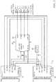
- Fig. 5is an electrical schematic of an ASIC 77 in accordance with an embodiment of the invention.
- Two modules 79, 81each receive 16 channels from a cardiac catheter (not shown) as input, denoted Ch0..Ch15, and CH16..Ch32, respectively.
- a five volt reference 83is connected to each of the modules 79, 81.
- a selected channel from the modules 79, 81is output on lines 85, 87 to analog-to-digital converter 89.
- the modules 79, 81include logical circuitry to switch the outputs on lines 85, 87. Both the reference 83 and the signal from the selected channel on lines 85, 87 are switched into the analog-to-digital converter 89.
- DPDT switchesincluded in the ASIC 77 first connect to a reference signal, and then to the incoming ECG signal to prevent charge injection and allow for fast settling time.
Landscapes
- Health & Medical Sciences (AREA)
- Life Sciences & Earth Sciences (AREA)
- Engineering & Computer Science (AREA)
- Surgery (AREA)
- Veterinary Medicine (AREA)
- Public Health (AREA)
- General Health & Medical Sciences (AREA)
- Animal Behavior & Ethology (AREA)
- Physics & Mathematics (AREA)
- Molecular Biology (AREA)
- Biomedical Technology (AREA)
- Heart & Thoracic Surgery (AREA)
- Medical Informatics (AREA)
- Biophysics (AREA)
- Pathology (AREA)
- Signal Processing (AREA)
- Cardiology (AREA)
- Physiology (AREA)
- Artificial Intelligence (AREA)
- Computer Vision & Pattern Recognition (AREA)
- Psychiatry (AREA)
- Otolaryngology (AREA)
- Plasma & Fusion (AREA)
- Nuclear Medicine, Radiotherapy & Molecular Imaging (AREA)
- Power Engineering (AREA)
- Measurement And Recording Of Electrical Phenomena And Electrical Characteristics Of The Living Body (AREA)
- Analogue/Digital Conversion (AREA)
Abstract
Description
- A portion of the disclosure of this patent document contains material that is subject to copyright protection. The copyright owner has no objection to the facsimile reproduction by anyone of the patent document or the patent disclosure, as it appears in the Patent and Trademark Office patent file or records, but otherwise reserves all copyright rights whatsoever.
- This invention relates to measurement of bioelectric currents. More particularly, this invention relates to systems for recording bioelectric signals from the heart using multiple channels.
- The meanings of certain acronyms and abbreviations used herein are given in Table 1.
Table 1 - Acronyms and Abbreviations ECG Electrocardiogram ASIC Application Specific Integrated Circuit DPDT Double Pole Double Throw MUX Multiplexer - A typical ECG system, such as the CARTO® 3 System, available from Biosense Webster, Inc., 3333 Diamond Canyon Road, Diamond Bar, CA 91765, receives multiple analog ECG signals simultaneously. Rather than digitizing each of the signals with a separate analog-to-digital -converter (A/D), the signals may be transferred via a multiplexer to a single digital-analog-converter. The output of the single digital-analog-converter is then de-multiplexed to recover the separate digitized signals.
- Multiplexers are known for dealing with separate signals. For example,
U.S. Patent No. 5,337,230 to Baumgartner et al. proposes a mixed analog and digital integrated circuit with features, which constitute a front end for physiological signal instrumentation. In one embodiment five 16-bit shift registers each provide 16 bits clocked out during each sample to a digital multiplexer. - In another example,
U.S. Patent No. 5,231,990 to Gauglitz describes an application specific integrated circuit (ASIC) for physiological monitoring that has multiple inputs and outputs in which multiple ASICs can be coupled together to expand the number of channels being monitored. Each ASIC has multiple inputs that may be coupled to the patient and analog expansion inputs to accept signals from other ASICs. The ASIC includes an analog multiplexer and sample/hold circuit to interface with an external analog to digital converter. - However, multiplexing the incoming ECG signals introduces switching noise into the signal output from the multiplexer. Some existing systems have attempted to mitigate this problem by making the analog channel differential and by using common-mode feedback at every stage of amplification. In another approach
U.S. Patent Application Publication No. 2015/0164354 describes an electrode configuration that proposes to reduce artifact induced in a single metallic electrode. The electrode is composed of two or more smaller electrodes that can be disconnected during a stimulation phase, and reconnected during a measurement phase. The electrode may be segmented, individual current sources being provided for each segment, forcing the current in the segments to match, and thereby reducing artifact. - According to disclosed embodiments of the invention, an ASIC multiplexes analog ECG signals from multiple channels for application in a physiologic monitoring system. In order to reduce the switching noise associated with the multiplexed signals, an electronic DPDT (double pole double throw) switch is incorporated into the multiplexer. The multiplexer switches between the ECG signals. At each switching event the DPDT switch first connects to a reference signal, and then to the incoming ECG signal.
- There is provided according to embodiments of the invention a method, which is carried out by receiving a plurality of analog bioelectric signals in respective channels and multiplexing the bioelectric signals in respective selection events. The selection events comprise making a first connection with a reference voltage, thereafter breaking the first connection and making a second connection with one of the bioelectric signals. The method is further carried out by outputting the multiplexed bioelectric signals to an analog-to-digital converter.
- According to one aspect of the method, making a first connection and making a second connection are accomplished by placing a double pole double throw switch in a first position and a second position, respectively.
- A further aspect of the method includes connecting a Wilson central terminal to a first input of a differential amplifier, connecting one of the bioelectric signals to a second input of the differential amplifier, and linking first and second outputs of the differential amplifier to the double pole double throw switch.
- Yet another aspect of the method includes interposing a buffer between the differential amplifier and the double pole double throw switch.
- There is further provided according to embodiments of the invention an apparatus including a catheter having an elongated distal portion and a plurality of electrodes on the distal portion for reading bioelectric signals. The apparatus includes a multiplexor having inputs connected to respective ones of the electrodes. A switch has a first input terminal connected to a reference signal, a second input terminal linked to the output of the multiplexor. Control circuitry linked to the switch and the multiplexor is operative to make a first connection between the output terminal of the switch and the reference signal via the first input terminal of the switch, and thereafter to break the first connection and to make a second connection between the output terminal of the switch and the output of the multiplexor via the second input terminal of the switch.
- In another aspect of the apparatus, the bioelectric signals are analog signals, and an analog-to-digital converter is connected to the output terminal of the switch and linked to a processor.
- According to an additional aspect of the apparatus, the switch is a double pole double throw switch.
- According to another aspect of the apparatus, the control circuitry includes a differential amplifier having first and second inputs connected to the first and second input terminals of the switch, respectively. The first input of the differential amplifier is connected to a Wilson central terminal, and the second input of the differential amplifier is linked to one of the bioelectric signals.
- According to one aspect of the apparatus, the Wilson central terminal is connected to a dynamic offset voltage.
- For a better understanding of the present invention, reference is made to the detailed description of the invention, by way of example, which is to be read in conjunction with the following drawings, wherein like elements are given like reference numerals, and wherein:
Fig. 1 is a pictorial illustration of an exemplary system for performing procedures on a heart of a living subject, which is constructed and operative in accordance with a disclosed embodiment of the invention;Fig. 2 is a schematic of a multiplexed arrangement for processing multi-channel ECG signals in accordance with an embodiment of the invention;Fig. 3 is an electrical schematic of one of the channels shown inFig. 2 in accordance with an embodiment of the invention;Fig. 4 is an electrical schematic of a portion of an electrical circuit showing multiple channels in accordance with an embodiment of the invention; andFig. 5 is an electrical schematic of an electrical circuit in accordance with an embodiment of the invention.- In the following description, numerous specific details are set forth in order to provide a thorough understanding of the various principles of the present invention. It will be apparent to one skilled in the art, however, that not all these details are necessarily needed for practicing the present invention. In this instance, well-known circuits, control logic, and the details of computer program instructions for conventional algorithms and processes have not been shown in detail in order not to obscure the general concepts unnecessarily.
- Documents incorporated by reference herein are to be considered an integral part of the application except that, to the extent that any terms are defined in these incorporated documents in a manner that conflicts with definitions made explicitly or implicitly in the present specification, only the definitions in the present specification should be considered.
- The terms "link", "links", "couple" and "couples" are intended to mean either an indirect or direct connection. Thus, if a first device couples to a second device, that connection may be through a direct connection, or through an indirect connection via other devices and connections.
- Turning now to the drawings, reference is initially made to
Fig. 1 , which is a pictorial illustration of anexemplary system 10 for performing procedures on aheart 12 of a living subject, which is constructed and operative in accordance with a disclosed embodiment of the invention. The system comprises acatheter 14, which is percutaneously inserted by anoperator 16 through the patient's vascular system into a chamber or vascular structure of theheart 12. Theoperator 16, who is typically a physician, brings the catheter'sdistal tip 18 into contact with the heart wall, for example, at an ablation target site. Electrical activation maps may be prepared, according to the methods disclosed inU.S. Patent Nos. 6,226,542 , and6,301,496 , and in commonly assignedU.S. Patent No. 6,892,091 , whose disclosures are herein incorporated by reference. It should be understood that the principles of the invention are not limited to systems such as thesystem 10, but may be applied to other systems in which bioelectric signals are received via multiple channels. - The
system 10 may comprise a general purpose or embedded computer processor, which is programmed with suitable software for carrying out the functions described hereinbelow. Thus, although portions of thesystem 10 shown in other drawing figures herein are shown as comprising a number of separate functional blocks, these blocks are not necessarily separate physical entities, but rather may represent, for example, different computing tasks or data objects stored in a memory that is accessible to the processor. These tasks may be carried out in software running on a single processor, or on multiple processors. The software may be provided to the processor or processors on tangible non-transitory media, such as CD-ROM or non-volatile memory. Alternatively or additionally, thesystem 10 may comprise a digital signal processor or hard-wired logic. One commercial product embodying elements of thesystem 10 is available as theCARTO® 3 System, available from Biosense Webster, Inc., 3333 Diamond Canyon Road, Diamond Bar, CA 91765. This system may be modified by those skilled in the art to embody the principles of the invention described herein. - Areas determined to be abnormal, for example by evaluation of the electrical activation maps, can be ablated by application of thermal energy, e.g., by passage of radiofrequency electrical current through wires in the catheter to one or more electrodes at the
distal tip 18, which apply the radiofrequency energy to the myocardium. The energy is absorbed in the tissue, heating it to a point (typically about 50°C) at which it permanently loses its electrical excitability. When successful, this procedure creates non-conducting lesions in the cardiac tissue, which disrupt the abnormal electrical pathway causing the arrhythmia. The principles of the invention can be applied to different heart chambers to diagnose and treat many different cardiac arrhythmias. - The
catheter 14 typically comprises ahandle 20, having suitable controls on the handle to enable theoperator 16 to steer, position and orient the distal end of the catheter as desired for the ablation. To aid theoperator 16, the distal portion of thecatheter 14 contains position sensors (not shown) that provide signals to aprocessor 22, located in aconsole 24. Theprocessor 22 may fulfill several processing functions as described below. - The
catheter 14 is a multi-electrode catheter, which can be a basket catheter as shown in the right portion of the balloon or a spline catheter as shown in the left portion. In any case there aremultiple electrodes 32, which are used as sensing electrodes and have known locations on the basket or spline, and known relationships to one another. Thus, once the catheter is located in the heart, for example by constructing a current position map, the location of each of theelectrodes 32 in the heart is known. One method for generation of a current position map is described in commonly assignedU.S. Patent No. 8,478,383 to Bar-Tal et al. , which is herein incorporated by reference. - Electrical signals can be conveyed to and from the
heart 12 from theelectrodes 32 located at or near thedistal tip 18 of thecatheter 14 via cable 34 to theconsole 24. Pacing signals and other control signals may be conveyed from theconsole 24 through the cable 34 and theelectrodes 32 to theheart 12. Wire connections 35 link theconsole 24 withbody surface electrodes 30 and other components of a positioning sub-system for measuring location and orientation coordinates of thecatheter 14. Theprocessor 22, or another processor (not shown) may be an element of the positioning subsystem. Theelectrodes 32 and thebody surface electrodes 30 may be used to measure tissue impedance at the ablation site as taught inU.S. Patent No. 7,536,218, issued to Govari et al. , which is herein incorporated by reference. A temperature sensor (not shown), typically a thermocouple or thermistor, may be mounted near thedistal tip 18 of thecatheter 14.- The
console 24 typically contains one or moreablation power generators 25. Thecatheter 14 may be adapted to conduct ablative energy to the heart using any known ablation technique, e.g., radiofrequency energy, ultrasound energy, and laser-produced light energy. Such methods are disclosed in commonly assignedU.S. Patent Nos. 6,814,733 ,6,997,924 , and7,156,816 , which are herein incorporated by reference. - In one embodiment, the positioning subsystem comprises a magnetic position tracking arrangement that determines the position and orientation of the
catheter 14 by generating magnetic fields in a predefined working volume and sensing these fields at the catheter, using field generating coils 28. The positioning subsystemU.S. Patent No. 7,756,576 , which is hereby incorporated by reference, and in the above-notedU.S. Patent No. 7,536,218 . - As noted above, the
catheter 14 is coupled to theconsole 24, which enables theoperator 16 to observe and regulate the functions of thecatheter 14.Console 24 includes a processor, preferably a computer with appropriate signal processing circuits. The processor is coupled to drive amonitor 29. The signal processing circuits typically receive, amplify, filter and digitize signals from thecatheter 14, including signals generated by the above-noted sensors and a plurality of location sensing electrodes (not shown) located distally in thecatheter 14. The digitized signals are received and used by theconsole 24 and the positioning system to compute the position and orientation of thecatheter 14 and to analyze the electrical signals from the electrodes as described in further detail below. - Typically, the
system 10 includes other elements, which are not shown in the figures for the sake of simplicity. For example, thesystem 10 may include an ECG monitor, coupled to receive signals from one or more body surface electrodes, so as to provide an ECG synchronization signal to theconsole 24. As mentioned above, thesystem 10 typically also includes a reference position sensor, either on an externally-applied reference patch attached to the exterior of the subject's body, or on an internally-placed catheter, which is inserted into theheart 12 maintained in a fixed position relative to theheart 12. Thesystem 10 may receive image data from an external imaging modality, such as an MRI unit or the like and includes image processors that can be incorporated in or invoked by theprocessor 22 for generating and displaying images. - In a typical application of the system 10 a chamber of the heart is catheterized conventionally with a multi-electrode catheter. Either a multi-spline catheter of a basket catheter is suitable. In such catheters each electrode has a known position on the basket or the splines as the case may be. Once the catheter is in place, if desired a current position map may be constructed using location sensors in the catheter, for example magnetic location sensors or using impedance measurements as noted above. The location of each of the electrodes in the heart is known from the current position map, or can be determined using imaging techniques. A typical multi-spline catheter used with the
system 10 has, on its distal end, 60 electrodes, which acquire 60 sets of ECG signals from 60 points in the heart. The electrodes are distributed over the splines, assumed herein to be eight splines. The signals may be presented as 60 voltage vs time graphs. Other suitable catheters may have relatively more or fewer electrodes. - Reference is now made to
Fig. 2 , which is a schematic of a multiplexed arrangement for processing multi-channel ECG signals in accordance with an embodiment of the invention. A terminal 37, comprising analog ECG signals in multiple channels 39, typically from respective electrodes of a multichannel catheter, such as shown inFig. 1 , is input to a multiplexer 41 (MUX), which selects each of the channels 39 in turn. Included in themultiplexer 41 is a double pole double throw (DPDT)switch 43, which first connects to areference signal 45 and then to the selected channel 39.Output 47 is sent to an analog-to-digital converter 49. - Reference is now made to
Fig. 3 , which is an electrical schematic of one of the channels 39 (Fig. 2 ) in accordance with an embodiment of the invention. AnECG input 51 and areference input 53, typically taken from a Wilson central terminal and modified by dynamic offset 55 are submitted to adifferential amplifier 57, thence through alow pass filter 59 andbuffer 61. Alternatively, thereference input 53 can be the average of all the electrodes. The buffer output is presented to aDPDT switch 63. In a closed position theDPDT switch 63 conveys the outputs of thebuffer 61 to an analog-to-digital converter. In an open position the output of the buffer is held at a reference voltage. - Reference is now made to
Fig. 4 , which is an electrical schematic of a portion of an ASIC showing multiple channels in accordance with an embodiment of the invention. Sixteen channels labeled IN0 - IN15 are arranged in twobanks selectors circuits circuits Fig.3 , in which DPDT switches 72, 74 have the function of DPDT switch 63 (Fig. 3 ). Each channel is selected for 5.88 µs, switched on for 1.47 µs (1/4 duty cycle) and off for 4.41 µs. typically 20,000 samples per channel are acquired. Thus, the analog-to-digital converter needs to sample at 640,000 samples/sec. (Note that the analog-to-digital converter services both of thecircuits 69, 74). The settling time must be less than 1.47 µs. - Reference is now made to
Fig. 5 , which is an electrical schematic of anASIC 77 in accordance with an embodiment of the invention. Twomodules volt reference 83 is connected to each of themodules modules lines 85, 87 to analog-to-digital converter 89. Themodules lines 85, 87. Both thereference 83 and the signal from the selected channel onlines 85, 87 are switched into the analog-to-digital converter 89. As explained above in the discussion ofFig. 3 andFig. 4 , at each switching event DPDT switches (not shown) included in theASIC 77 first connect to a reference signal, and then to the incoming ECG signal to prevent charge injection and allow for fast settling time. - It will be appreciated by persons skilled in the art that the present invention is not limited to what has been particularly shown and described hereinabove. Rather, the scope of the present invention includes both combinations and sub-combinations of the various features described hereinabove, as well as variations and modifications thereof that are not in the prior art, which would occur to persons skilled in the art upon reading the foregoing description.
Claims (9)
- A method, comprising the steps of:receiving a plurality of analog bioelectric signals in respective channels;multiplexing the bioelectric signals, in respective selection events, wherein the selection events comprise making a first connection with a reference voltage and thereafter breaking the first connection and making a second connection with one of the bioelectric signals; andoutputting the multiplexed bioelectric signals to an analog-to-digital converter.
- The method according to claim 1, wherein making a first connection and making a second connection are accomplished by placing a double pole double throw switch in a first position and a second position, respectively.
- The method according to claim 2, further comprising connecting a Wilson central terminal to a first input of a differential amplifier and connecting one of the bioelectric signals to a second input of the differential amplifier, and linking first and second outputs of the differential amplifier to the double pole double throw switch.
- The method according to claim 3, further comprising interposing a buffer between the differential amplifier and the double pole double throw switch.
- An apparatus comprising
a catheter having an elongated distal portion;
a plurality of electrodes on the distal portion for reading bioelectric signals:a multiplexor having inputs connected to respective ones of the electrodes and having an output;a switch having a first input terminal connected to a reference signal, a second input terminal linked to the output of the multiplexor, and an output terminal; andcontrol circuitry linked to the switch and the multiplexor and operative to make a first connection between the output terminal of the switch and the reference signal via the first input terminal of the switch; and thereafter to break the first connection and to make a second connection between the output terminal of the switch and the output of the multiplexor via the second input terminal of the switch. - The apparatus according to claim 5, wherein the bioelectric signals are analog signals, further comprising an analog-to-digital converter connected to the output terminal of the switch and linked to a processor.
- The apparatus according to claim 5, wherein the switch is a double pole double throw switch.
- The apparatus according to claim 5, wherein the control circuitry comprises a differential amplifier having first and second inputs and having first and second outputs connected to the first and second input terminals of the switch, respectively, wherein the first input of the differential amplifier is connected to a Wilson central terminal, and the second input of the differential amplifier is linked to one of the bioelectric signals.
- The apparatus according to claim 8, wherein the Wilson central terminal is connected to a dynamic offset voltage.
Priority Applications (1)
| Application Number | Priority Date | Filing Date | Title |
|---|---|---|---|
| EP19201252.4AEP3607880B1 (en) | 2016-11-14 | 2017-11-13 | Method for reducing switching noise in analog bioelectric signal processing |
Applications Claiming Priority (1)
| Application Number | Priority Date | Filing Date | Title |
|---|---|---|---|
| US15/350,236US10314507B2 (en) | 2016-11-14 | 2016-11-14 | ASIC with switching noise reduction |
Related Child Applications (2)
| Application Number | Title | Priority Date | Filing Date |
|---|---|---|---|
| EP19201252.4ADivision-IntoEP3607880B1 (en) | 2016-11-14 | 2017-11-13 | Method for reducing switching noise in analog bioelectric signal processing |
| EP19201252.4ADivisionEP3607880B1 (en) | 2016-11-14 | 2017-11-13 | Method for reducing switching noise in analog bioelectric signal processing |
Publications (2)
| Publication Number | Publication Date |
|---|---|
| EP3320838A1true EP3320838A1 (en) | 2018-05-16 |
| EP3320838B1 EP3320838B1 (en) | 2020-03-25 |
Family
ID=60387834
Family Applications (2)
| Application Number | Title | Priority Date | Filing Date |
|---|---|---|---|
| EP19201252.4AActiveEP3607880B1 (en) | 2016-11-14 | 2017-11-13 | Method for reducing switching noise in analog bioelectric signal processing |
| EP17201290.8AActiveEP3320838B1 (en) | 2016-11-14 | 2017-11-13 | Asic with switching noise reduction |
Family Applications Before (1)
| Application Number | Title | Priority Date | Filing Date |
|---|---|---|---|
| EP19201252.4AActiveEP3607880B1 (en) | 2016-11-14 | 2017-11-13 | Method for reducing switching noise in analog bioelectric signal processing |
Country Status (7)
| Country | Link |
|---|---|
| US (2) | US10314507B2 (en) |
| EP (2) | EP3607880B1 (en) |
| JP (1) | JP7058979B2 (en) |
| CN (1) | CN108065931B (en) |
| AU (1) | AU2017245378A1 (en) |
| CA (1) | CA2984950A1 (en) |
| IL (1) | IL255110B (en) |
Cited By (1)
| Publication number | Priority date | Publication date | Assignee | Title |
|---|---|---|---|---|
| EP3753479A1 (en)* | 2019-06-19 | 2020-12-23 | Biosense Webster (Israel) Ltd | Extension of electrocardiography (ecg) acquisition capabilities of catheter-based cardiac system |
Families Citing this family (26)
| Publication number | Priority date | Publication date | Assignee | Title |
|---|---|---|---|---|
| US10905329B2 (en) | 2016-06-09 | 2021-02-02 | Biosense Webster (Israel) Ltd. | Multi-function conducting elements for a catheter |
| US12029545B2 (en) | 2017-05-30 | 2024-07-09 | Biosense Webster (Israel) Ltd. | Catheter splines as location sensors |
| US20190314083A1 (en) | 2018-04-11 | 2019-10-17 | Biosense Webster (Israel) Ltd. | Flexible Multi-Arm Catheter with Diametrically Opposed Sensing Electrodes |
| US10686715B2 (en)* | 2018-05-09 | 2020-06-16 | Biosig Technologies, Inc. | Apparatus and methods for removing a large-signal voltage offset from a biomedical signal |
| US11218142B2 (en)* | 2018-06-25 | 2022-01-04 | Biosense Webster (Israel) Ltd. | Signal quality in a multiplexing system by actively disconnecting unused connections |
| US11045628B2 (en) | 2018-12-11 | 2021-06-29 | Biosense Webster (Israel) Ltd. | Balloon catheter with high articulation |
| US11207016B2 (en) | 2018-12-28 | 2021-12-28 | Biosense Webster (Israel) Ltd. | Mapping ECG signals using a multipole electrode assembly |
| US11850051B2 (en) | 2019-04-30 | 2023-12-26 | Biosense Webster (Israel) Ltd. | Mapping grid with high density electrode array |
| US11712172B2 (en) | 2019-07-18 | 2023-08-01 | Biosense Webster (Israel) Ltd. | Visual guidance for positioning a distal end of a medical probe |
| US11950930B2 (en) | 2019-12-12 | 2024-04-09 | Biosense Webster (Israel) Ltd. | Multi-dimensional acquisition of bipolar signals from a catheter |
| US11517218B2 (en) | 2019-12-20 | 2022-12-06 | Biosense Webster (Israel) Ltd. | Selective graphical presentation of electrophysiological parameters |
| US12232874B2 (en) | 2020-05-29 | 2025-02-25 | Biosense Webster (Israel) Ltd. | Electrode apparatus for diagnosis of arrhythmias |
| US11987017B2 (en) | 2020-06-08 | 2024-05-21 | Biosense Webster (Israel) Ltd. | Features to assist in assembly and testing of devices |
| US11406308B2 (en)* | 2020-07-14 | 2022-08-09 | Biosense Webster (Israel) Ltd. | Visualization and recordation system interface with virtual ground for biomedical system and methods |
| US12048479B2 (en) | 2020-09-10 | 2024-07-30 | Biosense Webster (Israel) Ltd. | Surface mounted electrode catheter |
| US11950841B2 (en) | 2020-09-22 | 2024-04-09 | Biosense Webster (Israel) Ltd. | Basket catheter having insulated ablation electrodes and diagnostic electrodes |
| US11950840B2 (en) | 2020-09-22 | 2024-04-09 | Biosense Webster (Israel) Ltd. | Basket catheter having insulated ablation electrodes |
| US12082875B2 (en) | 2020-09-24 | 2024-09-10 | Biosense Webster (Israel) Ltd | Balloon catheter having a coil for sensing tissue temperature and position of the balloon |
| US11974803B2 (en) | 2020-10-12 | 2024-05-07 | Biosense Webster (Israel) Ltd. | Basket catheter with balloon |
| US12201786B2 (en) | 2020-12-17 | 2025-01-21 | Biosense Webster (Israel) Ltd. | Measurement of distal end dimension of catheters using magnetic fields |
| US11918383B2 (en) | 2020-12-21 | 2024-03-05 | Biosense Webster (Israel) Ltd. | Visualizing performance of catheter electrodes |
| US12064170B2 (en) | 2021-05-13 | 2024-08-20 | Biosense Webster (Israel) Ltd. | Distal assembly for catheter with lumens running along spines |
| US12364426B2 (en) | 2021-08-12 | 2025-07-22 | Biosense Webster (Israel) Ltd. | Electro-anatomical mapping and annotation presented in electrophysiological procedures |
| US12004804B2 (en) | 2021-09-09 | 2024-06-11 | Biosense Webster (Israel) Ltd. | Basket catheter with mushroom shape distal tip |
| US12011280B2 (en) | 2021-10-04 | 2024-06-18 | Biosense Webster (Israel) Ltd. | Electrophysiological mapping in the presence of injury current |
| US12419683B2 (en) | 2021-12-22 | 2025-09-23 | Biosense Webster (Israel) Ltd. | Irreversible electroporation with shorted electrodes |
Citations (16)
| Publication number | Priority date | Publication date | Assignee | Title |
|---|---|---|---|---|
| US4751931A (en)* | 1986-09-22 | 1988-06-21 | Allegheny-Singer Research Institute | Method and apparatus for determining his-purkinje activity |
| US5231990A (en) | 1992-07-09 | 1993-08-03 | Spacelabs, Medical, Inc. | Application specific integrated circuit for physiological monitoring |
| US5337230A (en) | 1992-04-30 | 1994-08-09 | Hewlett-Packard Company | Signal processing circuits with digital programmability |
| JP2000059217A (en)* | 1998-08-12 | 2000-02-25 | Nec Corp | Analog-to-digital converter |
| US6226542B1 (en) | 1998-07-24 | 2001-05-01 | Biosense, Inc. | Three-dimensional reconstruction of intrabody organs |
| US6301496B1 (en) | 1998-07-24 | 2001-10-09 | Biosense, Inc. | Vector mapping of three-dimensionally reconstructed intrabody organs and method of display |
| US6814733B2 (en) | 2002-01-31 | 2004-11-09 | Biosense, Inc. | Radio frequency pulmonary vein isolation |
| US6892091B1 (en) | 2000-02-18 | 2005-05-10 | Biosense, Inc. | Catheter, method and apparatus for generating an electrical map of a chamber of the heart |
| US6997924B2 (en) | 2002-09-17 | 2006-02-14 | Biosense Inc. | Laser pulmonary vein isolation |
| US7156816B2 (en) | 2002-11-26 | 2007-01-02 | Biosense, Inc. | Ultrasound pulmonary vein isolation |
| US20080243013A1 (en)* | 2007-03-26 | 2008-10-02 | Denso Corporation | Biosignal measuring equipment |
| US7536218B2 (en) | 2005-07-15 | 2009-05-19 | Biosense Webster, Inc. | Hybrid magnetic-based and impedance-based position sensing |
| US7756576B2 (en) | 2005-08-26 | 2010-07-13 | Biosense Webster, Inc. | Position sensing and detection of skin impedance |
| US8478383B2 (en) | 2010-12-14 | 2013-07-02 | Biosense Webster (Israel), Ltd. | Probe tracking using multiple tracking methods |
| US20150164354A1 (en) | 2011-05-13 | 2015-06-18 | John Louis Parker | Method and apparatus for measurement of neural response |
| US20160008062A1 (en)* | 2006-06-28 | 2016-01-14 | Kardium Inc. | Apparatus and method for intra-cardiac mapping and ablation |
Family Cites Families (30)
| Publication number | Priority date | Publication date | Assignee | Title |
|---|---|---|---|---|
| US4467813A (en)* | 1982-05-04 | 1984-08-28 | Cardiac Resuscitator Corporation | Biological signal source amplifier |
| US5042499A (en) | 1988-09-30 | 1991-08-27 | Frank Thomas H | Noninvasive electrocardiographic method of real time signal processing for obtaining and displaying instantaneous fetal heart rate and fetal heart rate beat-to-beat variability |
| US5579764A (en)* | 1993-01-08 | 1996-12-03 | Goldreyer; Bruce N. | Method and apparatus for spatially specific electrophysiological sensing in a catheter with an enlarged ablating electrode |
| US5555888A (en) | 1995-02-27 | 1996-09-17 | Brewer; James E. | Method for automatic, adaptive, active facilitation to access myocardial electrical instability |
| GB9626512D0 (en) | 1996-12-20 | 1997-02-05 | Gyrus Medical Ltd | An improved electrosurgical generator and system |
| US5792203A (en)* | 1997-08-18 | 1998-08-11 | Sulzer Intermedics Inc. | Universal programmable cardiac stimulation device |
| US6295473B1 (en)* | 1999-04-16 | 2001-09-25 | Medtronic, Inc. | Digital delay line receiver for use with an implantable medical device |
| US6300837B1 (en)* | 2000-03-28 | 2001-10-09 | Philips Electronics North America Corporation | Dynamic bias boosting circuit for a power amplifier |
| US6584345B2 (en)* | 2001-03-13 | 2003-06-24 | Biosense, Inc. | Apparatus and method for measuring a plurality of electrical signals from the body of a patient |
| US6635047B2 (en) | 2001-08-06 | 2003-10-21 | Scimed Life Systems, Inc. | Integrated polymer and braid for intravascular catheters |
| US7640053B2 (en)* | 2002-06-26 | 2009-12-29 | Endosense S.A. | Catheterization method and system for controlling tip displacement |
| US20050075672A1 (en)* | 2003-10-06 | 2005-04-07 | Rottenberg William B. | Cardiac Stimulation Apparatus With Multiple Input Sense Amplifiers |
| US8185191B1 (en) | 2003-12-29 | 2012-05-22 | Michael Evan Shapiro | Pulse monitoring and warning system for infants |
| US8697205B2 (en) | 2005-05-17 | 2014-04-15 | St. Jude Medical Ab | Elastomeric tube and method of making same |
| SE529087C8 (en)* | 2006-02-15 | 2007-05-08 | Wireless generation of standard type ECG leads | |
| JP4779793B2 (en)* | 2006-05-01 | 2011-09-28 | 株式会社デンソー | AD converter and electronic control device |
| US8200317B2 (en)* | 2006-06-30 | 2012-06-12 | Intel Corporation | Method and apparatus for amplifying multiple signals using a single multiplexed amplifier channel with software controlled AC response |
| CN100571612C (en)* | 2007-07-13 | 2009-12-23 | 深圳迪美泰数字医学技术有限公司 | The pure digital medical amplifier that is used for clinical or non-clinical bio signal record |
| KR101127341B1 (en)* | 2010-07-16 | 2012-03-29 | 엘에스산전 주식회사 | Apparatus for protecting overvoltage of analog input module |
| WO2012167096A2 (en) | 2011-06-03 | 2012-12-06 | The Board Of Trustees Of The University Of Illinois | Conformable actively multiplexed high-density surface electrode array for brain interfacing |
| CN102488509B (en)* | 2011-11-14 | 2015-02-25 | 深圳市理邦精密仪器股份有限公司 | Device and method for acquiring biological electric signals |
| US8676012B2 (en) | 2012-01-20 | 2014-03-18 | Corning Cable Systems Llc | Fiber optic cable for very-short-distance networks |
| US8577450B1 (en)* | 2012-07-23 | 2013-11-05 | Biosense Webster (Israel) Ltd. | Graphic interface for multi-spine probe |
| US20160038657A1 (en) | 2013-03-15 | 2016-02-11 | Raymond Lareau | Medical devices having surface modifiers |
| EP2986204B1 (en)* | 2013-04-16 | 2018-08-22 | Alivecor, Inc. | Two electrode apparatus and methods for twelve lead ecg |
| US9615760B2 (en) | 2013-06-17 | 2017-04-11 | Biosense Webster (Israel), Ltd. | Multiple bipolar sampling |
| CN103356183B (en)* | 2013-07-05 | 2016-02-17 | 中国科学院深圳先进技术研究院 | ECG acquisition platform |
| CN104799846A (en)* | 2015-05-12 | 2015-07-29 | 孙英贤 | Conversion device and conversion method for wirelessly transmitting electrocardiograph monitoring signal |
| CN105615869A (en)* | 2015-12-31 | 2016-06-01 | 武汉明德生物科技股份有限公司 | 12-lead electrocardiograph signal acquisition device |
| CN105769179B (en)* | 2016-04-29 | 2018-04-20 | 上海夏先机电科技发展有限公司 | A kind of portable 12 lead electrocardiosignal synchronous acquisition device |
- 2016
- 2016-11-14USUS15/350,236patent/US10314507B2/enactiveActive
- 2017
- 2017-10-12AUAU2017245378Apatent/AU2017245378A1/ennot_activeAbandoned
- 2017-10-18ILIL255110Apatent/IL255110B/enactiveIP Right Grant
- 2017-11-08CACA2984950Apatent/CA2984950A1/ennot_activeAbandoned
- 2017-11-13EPEP19201252.4Apatent/EP3607880B1/enactiveActive
- 2017-11-13EPEP17201290.8Apatent/EP3320838B1/enactiveActive
- 2017-11-13JPJP2017217966Apatent/JP7058979B2/enactiveActive
- 2017-11-14CNCN201711121229.0Apatent/CN108065931B/enactiveActive
- 2019
- 2019-04-24USUS16/393,790patent/US10863914B2/enactiveActive
Patent Citations (16)
| Publication number | Priority date | Publication date | Assignee | Title |
|---|---|---|---|---|
| US4751931A (en)* | 1986-09-22 | 1988-06-21 | Allegheny-Singer Research Institute | Method and apparatus for determining his-purkinje activity |
| US5337230A (en) | 1992-04-30 | 1994-08-09 | Hewlett-Packard Company | Signal processing circuits with digital programmability |
| US5231990A (en) | 1992-07-09 | 1993-08-03 | Spacelabs, Medical, Inc. | Application specific integrated circuit for physiological monitoring |
| US6226542B1 (en) | 1998-07-24 | 2001-05-01 | Biosense, Inc. | Three-dimensional reconstruction of intrabody organs |
| US6301496B1 (en) | 1998-07-24 | 2001-10-09 | Biosense, Inc. | Vector mapping of three-dimensionally reconstructed intrabody organs and method of display |
| JP2000059217A (en)* | 1998-08-12 | 2000-02-25 | Nec Corp | Analog-to-digital converter |
| US6892091B1 (en) | 2000-02-18 | 2005-05-10 | Biosense, Inc. | Catheter, method and apparatus for generating an electrical map of a chamber of the heart |
| US6814733B2 (en) | 2002-01-31 | 2004-11-09 | Biosense, Inc. | Radio frequency pulmonary vein isolation |
| US6997924B2 (en) | 2002-09-17 | 2006-02-14 | Biosense Inc. | Laser pulmonary vein isolation |
| US7156816B2 (en) | 2002-11-26 | 2007-01-02 | Biosense, Inc. | Ultrasound pulmonary vein isolation |
| US7536218B2 (en) | 2005-07-15 | 2009-05-19 | Biosense Webster, Inc. | Hybrid magnetic-based and impedance-based position sensing |
| US7756576B2 (en) | 2005-08-26 | 2010-07-13 | Biosense Webster, Inc. | Position sensing and detection of skin impedance |
| US20160008062A1 (en)* | 2006-06-28 | 2016-01-14 | Kardium Inc. | Apparatus and method for intra-cardiac mapping and ablation |
| US20080243013A1 (en)* | 2007-03-26 | 2008-10-02 | Denso Corporation | Biosignal measuring equipment |
| US8478383B2 (en) | 2010-12-14 | 2013-07-02 | Biosense Webster (Israel), Ltd. | Probe tracking using multiple tracking methods |
| US20150164354A1 (en) | 2011-05-13 | 2015-06-18 | John Louis Parker | Method and apparatus for measurement of neural response |
Cited By (1)
| Publication number | Priority date | Publication date | Assignee | Title |
|---|---|---|---|---|
| EP3753479A1 (en)* | 2019-06-19 | 2020-12-23 | Biosense Webster (Israel) Ltd | Extension of electrocardiography (ecg) acquisition capabilities of catheter-based cardiac system |
Also Published As
| Publication number | Publication date |
|---|---|
| EP3320838B1 (en) | 2020-03-25 |
| US20180132749A1 (en) | 2018-05-17 |
| AU2017245378A1 (en) | 2018-05-31 |
| JP7058979B2 (en) | 2022-04-25 |
| US10863914B2 (en) | 2020-12-15 |
| EP3607880B1 (en) | 2022-01-26 |
| CA2984950A1 (en) | 2018-05-14 |
| IL255110B (en) | 2020-10-29 |
| IL255110A0 (en) | 2017-12-31 |
| EP3607880A1 (en) | 2020-02-12 |
| CN108065931A (en) | 2018-05-25 |
| US20190246935A1 (en) | 2019-08-15 |
| US10314507B2 (en) | 2019-06-11 |
| CN108065931B (en) | 2022-07-05 |
| JP2018079322A (en) | 2018-05-24 |
Similar Documents
| Publication | Publication Date | Title |
|---|---|---|
| US10863914B2 (en) | ASIC with switching noise reduction | |
| US12285259B2 (en) | Identification and visualization of cardiac activation sequence in multi-channel recordings | |
| US10045707B2 (en) | Basket catheter with far-field electrode | |
| EP3453323A1 (en) | Automatic display of earliest lat point | |
| US10974031B2 (en) | Balloon catheter with internal distal end | |
| US11207125B2 (en) | Effective parasitic capacitance minimization for micro ablation electrode | |
| JP2021094390A (en) | Tissue proximity indication based on subset of electrodes | |
| US20210401348A1 (en) | Signal color morphology | |
| CN109419502A (en) | For sensing the medical patch of ECG signal and impedance instruction electric signal simultaneously | |
| JP7691046B2 (en) | Signal quality in multiplexed systems by actively disconnecting unused connections |
Legal Events
| Date | Code | Title | Description |
|---|---|---|---|
| PUAI | Public reference made under article 153(3) epc to a published international application that has entered the european phase | Free format text:ORIGINAL CODE: 0009012 | |
| STAA | Information on the status of an ep patent application or granted ep patent | Free format text:STATUS: THE APPLICATION HAS BEEN PUBLISHED | |
| AK | Designated contracting states | Kind code of ref document:A1 Designated state(s):AL AT BE BG CH CY CZ DE DK EE ES FI FR GB GR HR HU IE IS IT LI LT LU LV MC MK MT NL NO PL PT RO RS SE SI SK SM TR | |
| AX | Request for extension of the european patent | Extension state:BA ME | |
| STAA | Information on the status of an ep patent application or granted ep patent | Free format text:STATUS: REQUEST FOR EXAMINATION WAS MADE | |
| 17P | Request for examination filed | Effective date:20181106 | |
| RBV | Designated contracting states (corrected) | Designated state(s):AL AT BE BG CH CY CZ DE DK EE ES FI FR GB GR HR HU IE IS IT LI LT LU LV MC MK MT NL NO PL PT RO RS SE SI SK SM TR | |
| GRAP | Despatch of communication of intention to grant a patent | Free format text:ORIGINAL CODE: EPIDOSNIGR1 | |
| STAA | Information on the status of an ep patent application or granted ep patent | Free format text:STATUS: GRANT OF PATENT IS INTENDED | |
| RIC1 | Information provided on ipc code assigned before grant | Ipc:A61B 18/14 20060101ALI20190531BHEP Ipc:A61B 5/0428 20060101AFI20190531BHEP Ipc:A61B 5/00 20060101ALI20190531BHEP Ipc:A61B 5/042 20060101ALI20190531BHEP Ipc:A61B 18/00 20060101ALN20190531BHEP Ipc:A61B 5/0408 20060101ALI20190531BHEP | |
| INTG | Intention to grant announced | Effective date:20190703 | |
| GRAJ | Information related to disapproval of communication of intention to grant by the applicant or resumption of examination proceedings by the epo deleted | Free format text:ORIGINAL CODE: EPIDOSDIGR1 | |
| STAA | Information on the status of an ep patent application or granted ep patent | Free format text:STATUS: REQUEST FOR EXAMINATION WAS MADE | |
| GRAP | Despatch of communication of intention to grant a patent | Free format text:ORIGINAL CODE: EPIDOSNIGR1 | |
| STAA | Information on the status of an ep patent application or granted ep patent | Free format text:STATUS: GRANT OF PATENT IS INTENDED | |
| INTC | Intention to grant announced (deleted) | ||
| RIC1 | Information provided on ipc code assigned before grant | Ipc:A61B 18/00 20060101ALN20191118BHEP Ipc:A61B 5/0408 20060101ALI20191118BHEP Ipc:A61B 5/042 20060101ALI20191118BHEP Ipc:A61B 5/0428 20060101AFI20191118BHEP Ipc:A61B 18/14 20060101ALI20191118BHEP Ipc:A61B 5/00 20060101ALI20191118BHEP | |
| INTG | Intention to grant announced | Effective date:20191206 | |
| GRAS | Grant fee paid | Free format text:ORIGINAL CODE: EPIDOSNIGR3 | |
| GRAA | (expected) grant | Free format text:ORIGINAL CODE: 0009210 | |
| STAA | Information on the status of an ep patent application or granted ep patent | Free format text:STATUS: THE PATENT HAS BEEN GRANTED | |
| AK | Designated contracting states | Kind code of ref document:B1 Designated state(s):AL AT BE BG CH CY CZ DE DK EE ES FI FR GB GR HR HU IE IS IT LI LT LU LV MC MK MT NL NO PL PT RO RS SE SI SK SM TR | |
| REG | Reference to a national code | Ref country code:GB Ref legal event code:FG4D | |
| REG | Reference to a national code | Ref country code:DE Ref legal event code:R096 Ref document number:602017013554 Country of ref document:DE | |
| REG | Reference to a national code | Ref country code:AT Ref legal event code:REF Ref document number:1247589 Country of ref document:AT Kind code of ref document:T Effective date:20200415 Ref country code:IE Ref legal event code:FG4D | |
| REG | Reference to a national code | Ref country code:NL Ref legal event code:FP | |
| PG25 | Lapsed in a contracting state [announced via postgrant information from national office to epo] | Ref country code:FI Free format text:LAPSE BECAUSE OF FAILURE TO SUBMIT A TRANSLATION OF THE DESCRIPTION OR TO PAY THE FEE WITHIN THE PRESCRIBED TIME-LIMIT Effective date:20200325 Ref country code:NO Free format text:LAPSE BECAUSE OF FAILURE TO SUBMIT A TRANSLATION OF THE DESCRIPTION OR TO PAY THE FEE WITHIN THE PRESCRIBED TIME-LIMIT Effective date:20200625 Ref country code:RS Free format text:LAPSE BECAUSE OF FAILURE TO SUBMIT A TRANSLATION OF THE DESCRIPTION OR TO PAY THE FEE WITHIN THE PRESCRIBED TIME-LIMIT Effective date:20200325 | |
| PG25 | Lapsed in a contracting state [announced via postgrant information from national office to epo] | Ref country code:SE Free format text:LAPSE BECAUSE OF FAILURE TO SUBMIT A TRANSLATION OF THE DESCRIPTION OR TO PAY THE FEE WITHIN THE PRESCRIBED TIME-LIMIT Effective date:20200325 Ref country code:LV Free format text:LAPSE BECAUSE OF FAILURE TO SUBMIT A TRANSLATION OF THE DESCRIPTION OR TO PAY THE FEE WITHIN THE PRESCRIBED TIME-LIMIT Effective date:20200325 Ref country code:HR Free format text:LAPSE BECAUSE OF FAILURE TO SUBMIT A TRANSLATION OF THE DESCRIPTION OR TO PAY THE FEE WITHIN THE PRESCRIBED TIME-LIMIT Effective date:20200325 Ref country code:GR Free format text:LAPSE BECAUSE OF FAILURE TO SUBMIT A TRANSLATION OF THE DESCRIPTION OR TO PAY THE FEE WITHIN THE PRESCRIBED TIME-LIMIT Effective date:20200626 Ref country code:BG Free format text:LAPSE BECAUSE OF FAILURE TO SUBMIT A TRANSLATION OF THE DESCRIPTION OR TO PAY THE FEE WITHIN THE PRESCRIBED TIME-LIMIT Effective date:20200625 | |
| REG | Reference to a national code | Ref country code:LT Ref legal event code:MG4D | |
| PG25 | Lapsed in a contracting state [announced via postgrant information from national office to epo] | Ref country code:SM Free format text:LAPSE BECAUSE OF FAILURE TO SUBMIT A TRANSLATION OF THE DESCRIPTION OR TO PAY THE FEE WITHIN THE PRESCRIBED TIME-LIMIT Effective date:20200325 Ref country code:LT Free format text:LAPSE BECAUSE OF FAILURE TO SUBMIT A TRANSLATION OF THE DESCRIPTION OR TO PAY THE FEE WITHIN THE PRESCRIBED TIME-LIMIT Effective date:20200325 Ref country code:EE Free format text:LAPSE BECAUSE OF FAILURE TO SUBMIT A TRANSLATION OF THE DESCRIPTION OR TO PAY THE FEE WITHIN THE PRESCRIBED TIME-LIMIT Effective date:20200325 Ref country code:RO Free format text:LAPSE BECAUSE OF FAILURE TO SUBMIT A TRANSLATION OF THE DESCRIPTION OR TO PAY THE FEE WITHIN THE PRESCRIBED TIME-LIMIT Effective date:20200325 Ref country code:PT Free format text:LAPSE BECAUSE OF FAILURE TO SUBMIT A TRANSLATION OF THE DESCRIPTION OR TO PAY THE FEE WITHIN THE PRESCRIBED TIME-LIMIT Effective date:20200818 Ref country code:CZ Free format text:LAPSE BECAUSE OF FAILURE TO SUBMIT A TRANSLATION OF THE DESCRIPTION OR TO PAY THE FEE WITHIN THE PRESCRIBED TIME-LIMIT Effective date:20200325 Ref country code:IS Free format text:LAPSE BECAUSE OF FAILURE TO SUBMIT A TRANSLATION OF THE DESCRIPTION OR TO PAY THE FEE WITHIN THE PRESCRIBED TIME-LIMIT Effective date:20200725 Ref country code:SK Free format text:LAPSE BECAUSE OF FAILURE TO SUBMIT A TRANSLATION OF THE DESCRIPTION OR TO PAY THE FEE WITHIN THE PRESCRIBED TIME-LIMIT Effective date:20200325 | |
| REG | Reference to a national code | Ref country code:AT Ref legal event code:MK05 Ref document number:1247589 Country of ref document:AT Kind code of ref document:T Effective date:20200325 | |
| REG | Reference to a national code | Ref country code:DE Ref legal event code:R079 Ref document number:602017013554 Country of ref document:DE Free format text:PREVIOUS MAIN CLASS: A61B0005042800 Ipc:A61B0005308000 | |
| REG | Reference to a national code | Ref country code:DE Ref legal event code:R097 Ref document number:602017013554 Country of ref document:DE | |
| PG25 | Lapsed in a contracting state [announced via postgrant information from national office to epo] | Ref country code:ES Free format text:LAPSE BECAUSE OF FAILURE TO SUBMIT A TRANSLATION OF THE DESCRIPTION OR TO PAY THE FEE WITHIN THE PRESCRIBED TIME-LIMIT Effective date:20200325 Ref country code:AT Free format text:LAPSE BECAUSE OF FAILURE TO SUBMIT A TRANSLATION OF THE DESCRIPTION OR TO PAY THE FEE WITHIN THE PRESCRIBED TIME-LIMIT Effective date:20200325 Ref country code:DK Free format text:LAPSE BECAUSE OF FAILURE TO SUBMIT A TRANSLATION OF THE DESCRIPTION OR TO PAY THE FEE WITHIN THE PRESCRIBED TIME-LIMIT Effective date:20200325 | |
| PLBE | No opposition filed within time limit | Free format text:ORIGINAL CODE: 0009261 | |
| STAA | Information on the status of an ep patent application or granted ep patent | Free format text:STATUS: NO OPPOSITION FILED WITHIN TIME LIMIT | |
| PG25 | Lapsed in a contracting state [announced via postgrant information from national office to epo] | Ref country code:PL Free format text:LAPSE BECAUSE OF FAILURE TO SUBMIT A TRANSLATION OF THE DESCRIPTION OR TO PAY THE FEE WITHIN THE PRESCRIBED TIME-LIMIT Effective date:20200325 | |
| 26N | No opposition filed | Effective date:20210112 | |
| PG25 | Lapsed in a contracting state [announced via postgrant information from national office to epo] | Ref country code:SI Free format text:LAPSE BECAUSE OF FAILURE TO SUBMIT A TRANSLATION OF THE DESCRIPTION OR TO PAY THE FEE WITHIN THE PRESCRIBED TIME-LIMIT Effective date:20200325 | |
| PG25 | Lapsed in a contracting state [announced via postgrant information from national office to epo] | Ref country code:MC Free format text:LAPSE BECAUSE OF FAILURE TO SUBMIT A TRANSLATION OF THE DESCRIPTION OR TO PAY THE FEE WITHIN THE PRESCRIBED TIME-LIMIT Effective date:20200325 | |
| REG | Reference to a national code | Ref country code:CH Ref legal event code:PL | |
| PG25 | Lapsed in a contracting state [announced via postgrant information from national office to epo] | Ref country code:LU Free format text:LAPSE BECAUSE OF NON-PAYMENT OF DUE FEES Effective date:20201113 | |
| REG | Reference to a national code | Ref country code:BE Ref legal event code:MM Effective date:20201130 | |
| PG25 | Lapsed in a contracting state [announced via postgrant information from national office to epo] | Ref country code:LI Free format text:LAPSE BECAUSE OF NON-PAYMENT OF DUE FEES Effective date:20201130 Ref country code:CH Free format text:LAPSE BECAUSE OF NON-PAYMENT OF DUE FEES Effective date:20201130 | |
| PG25 | Lapsed in a contracting state [announced via postgrant information from national office to epo] | Ref country code:IE Free format text:LAPSE BECAUSE OF NON-PAYMENT OF DUE FEES Effective date:20201113 | |
| PG25 | Lapsed in a contracting state [announced via postgrant information from national office to epo] | Ref country code:TR Free format text:LAPSE BECAUSE OF FAILURE TO SUBMIT A TRANSLATION OF THE DESCRIPTION OR TO PAY THE FEE WITHIN THE PRESCRIBED TIME-LIMIT Effective date:20200325 Ref country code:MT Free format text:LAPSE BECAUSE OF FAILURE TO SUBMIT A TRANSLATION OF THE DESCRIPTION OR TO PAY THE FEE WITHIN THE PRESCRIBED TIME-LIMIT Effective date:20200325 Ref country code:CY Free format text:LAPSE BECAUSE OF FAILURE TO SUBMIT A TRANSLATION OF THE DESCRIPTION OR TO PAY THE FEE WITHIN THE PRESCRIBED TIME-LIMIT Effective date:20200325 | |
| PG25 | Lapsed in a contracting state [announced via postgrant information from national office to epo] | Ref country code:MK Free format text:LAPSE BECAUSE OF FAILURE TO SUBMIT A TRANSLATION OF THE DESCRIPTION OR TO PAY THE FEE WITHIN THE PRESCRIBED TIME-LIMIT Effective date:20200325 Ref country code:AL Free format text:LAPSE BECAUSE OF FAILURE TO SUBMIT A TRANSLATION OF THE DESCRIPTION OR TO PAY THE FEE WITHIN THE PRESCRIBED TIME-LIMIT Effective date:20200325 | |
| PG25 | Lapsed in a contracting state [announced via postgrant information from national office to epo] | Ref country code:BE Free format text:LAPSE BECAUSE OF NON-PAYMENT OF DUE FEES Effective date:20201130 | |
| PGFP | Annual fee paid to national office [announced via postgrant information from national office to epo] | Ref country code:NL Payment date:20221019 Year of fee payment:6 | |
| REG | Reference to a national code | Ref country code:NL Ref legal event code:MM Effective date:20231201 | |
| PG25 | Lapsed in a contracting state [announced via postgrant information from national office to epo] | Ref country code:NL Free format text:LAPSE BECAUSE OF NON-PAYMENT OF DUE FEES Effective date:20231201 | |
| PG25 | Lapsed in a contracting state [announced via postgrant information from national office to epo] | Ref country code:NL Free format text:LAPSE BECAUSE OF NON-PAYMENT OF DUE FEES Effective date:20231201 | |
| PGFP | Annual fee paid to national office [announced via postgrant information from national office to epo] | Ref country code:DE Payment date:20241001 Year of fee payment:8 | |
| PGFP | Annual fee paid to national office [announced via postgrant information from national office to epo] | Ref country code:GB Payment date:20241001 Year of fee payment:8 | |
| PGFP | Annual fee paid to national office [announced via postgrant information from national office to epo] | Ref country code:FR Payment date:20241001 Year of fee payment:8 | |
| PGFP | Annual fee paid to national office [announced via postgrant information from national office to epo] | Ref country code:IT Payment date:20241010 Year of fee payment:8 |