EP3318915B1 - Method for determining an optical performance of a head mounted display device - Google Patents
Method for determining an optical performance of a head mounted display deviceDownload PDFInfo
- Publication number
- EP3318915B1 EP3318915B1EP16306447.0AEP16306447AEP3318915B1EP 3318915 B1EP3318915 B1EP 3318915B1EP 16306447 AEP16306447 AEP 16306447AEP 3318915 B1EP3318915 B1EP 3318915B1
- Authority
- EP
- European Patent Office
- Prior art keywords
- optical
- head mounted
- pupil
- display device
- mounted display
- Prior art date
- Legal status (The legal status is an assumption and is not a legal conclusion. Google has not performed a legal analysis and makes no representation as to the accuracy of the status listed.)
- Active
Links
Images


Classifications
- G—PHYSICS
- G01—MEASURING; TESTING
- G01J—MEASUREMENT OF INTENSITY, VELOCITY, SPECTRAL CONTENT, POLARISATION, PHASE OR PULSE CHARACTERISTICS OF INFRARED, VISIBLE OR ULTRAVIOLET LIGHT; COLORIMETRY; RADIATION PYROMETRY
- G01J3/00—Spectrometry; Spectrophotometry; Monochromators; Measuring colours
- G01J3/46—Measurement of colour; Colour measuring devices, e.g. colorimeters
- G01J3/50—Measurement of colour; Colour measuring devices, e.g. colorimeters using electric radiation detectors
- G01J3/506—Measurement of colour; Colour measuring devices, e.g. colorimeters using electric radiation detectors measuring the colour produced by screens, monitors, displays or CRTs
- G—PHYSICS
- G02—OPTICS
- G02B—OPTICAL ELEMENTS, SYSTEMS OR APPARATUS
- G02B26/00—Optical devices or arrangements for the control of light using movable or deformable optical elements
- G02B26/007—Optical devices or arrangements for the control of light using movable or deformable optical elements the movable or deformable optical element controlling the colour, i.e. a spectral characteristic, of the light
- G02B26/008—Optical devices or arrangements for the control of light using movable or deformable optical elements the movable or deformable optical element controlling the colour, i.e. a spectral characteristic, of the light in the form of devices for effecting sequential colour changes, e.g. colour wheels
- G—PHYSICS
- G02—OPTICS
- G02B—OPTICAL ELEMENTS, SYSTEMS OR APPARATUS
- G02B27/00—Optical systems or apparatus not provided for by any of the groups G02B1/00 - G02B26/00, G02B30/00
- G02B27/01—Head-up displays
- G02B27/017—Head mounted
- G02B27/0172—Head mounted characterised by optical features
- G—PHYSICS
- G01—MEASURING; TESTING
- G01M—TESTING STATIC OR DYNAMIC BALANCE OF MACHINES OR STRUCTURES; TESTING OF STRUCTURES OR APPARATUS, NOT OTHERWISE PROVIDED FOR
- G01M11/00—Testing of optical apparatus; Testing structures by optical methods not otherwise provided for
- G01M11/02—Testing optical properties
- G01M11/0242—Testing optical properties by measuring geometrical properties or aberrations
- G01M11/0257—Testing optical properties by measuring geometrical properties or aberrations by analyzing the image formed by the object to be tested
- G—PHYSICS
- G02—OPTICS
- G02B—OPTICAL ELEMENTS, SYSTEMS OR APPARATUS
- G02B27/00—Optical systems or apparatus not provided for by any of the groups G02B1/00 - G02B26/00, G02B30/00
- G02B27/01—Head-up displays
- G02B27/017—Head mounted
- G—PHYSICS
- G02—OPTICS
- G02B—OPTICAL ELEMENTS, SYSTEMS OR APPARATUS
- G02B27/00—Optical systems or apparatus not provided for by any of the groups G02B1/00 - G02B26/00, G02B30/00
- G02B27/01—Head-up displays
- G02B27/017—Head mounted
- G02B27/0176—Head mounted characterised by mechanical features
- G—PHYSICS
- G02—OPTICS
- G02B—OPTICAL ELEMENTS, SYSTEMS OR APPARATUS
- G02B27/00—Optical systems or apparatus not provided for by any of the groups G02B1/00 - G02B26/00, G02B30/00
- G02B27/62—Optical apparatus specially adapted for adjusting optical elements during the assembly of optical systems
- G—PHYSICS
- G02—OPTICS
- G02B—OPTICAL ELEMENTS, SYSTEMS OR APPARATUS
- G02B3/00—Simple or compound lenses
- G02B3/12—Fluid-filled or evacuated lenses
- G—PHYSICS
- G06—COMPUTING OR CALCULATING; COUNTING
- G06T—IMAGE DATA PROCESSING OR GENERATION, IN GENERAL
- G06T7/00—Image analysis
- G06T7/90—Determination of colour characteristics
- G—PHYSICS
- G02—OPTICS
- G02B—OPTICAL ELEMENTS, SYSTEMS OR APPARATUS
- G02B27/00—Optical systems or apparatus not provided for by any of the groups G02B1/00 - G02B26/00, G02B30/00
- G02B27/01—Head-up displays
- G02B27/0101—Head-up displays characterised by optical features
- G02B2027/011—Head-up displays characterised by optical features comprising device for correcting geometrical aberrations, distortion
- G—PHYSICS
- G02—OPTICS
- G02B—OPTICAL ELEMENTS, SYSTEMS OR APPARATUS
- G02B27/00—Optical systems or apparatus not provided for by any of the groups G02B1/00 - G02B26/00, G02B30/00
- G02B27/01—Head-up displays
- G02B27/0101—Head-up displays characterised by optical features
- G02B2027/0112—Head-up displays characterised by optical features comprising device for genereting colour display
- G—PHYSICS
- G02—OPTICS
- G02B—OPTICAL ELEMENTS, SYSTEMS OR APPARATUS
- G02B27/00—Optical systems or apparatus not provided for by any of the groups G02B1/00 - G02B26/00, G02B30/00
- G02B27/01—Head-up displays
- G02B27/0149—Head-up displays characterised by mechanical features
- G02B2027/0154—Head-up displays characterised by mechanical features with movable elements
- G02B2027/0159—Head-up displays characterised by mechanical features with movable elements with mechanical means other than scaning means for positioning the whole image
- G—PHYSICS
- G02—OPTICS
- G02B—OPTICAL ELEMENTS, SYSTEMS OR APPARATUS
- G02B27/00—Optical systems or apparatus not provided for by any of the groups G02B1/00 - G02B26/00, G02B30/00
- G02B27/01—Head-up displays
- G02B27/017—Head mounted
- G02B2027/0178—Eyeglass type
Definitions
- the inventionrelates to a method for determining an optical performance parameter of a head mounted display device adapted for a wearer and a method of assembling a head mounted display device adapted for a wearer.
- the inventionfurther relates to imaging photo-colorimeter having a pupil shift element.
- Head mounted display devicesare becoming more and more popular. Such type of device usually comprise a display element adapted to display images to the wearer of the head mounted device. Examples of such head mounter display devices are disclosed in WO 2007/125257 A1 , JP 2006 203440 A , WO 2007/048929 A1 and Gabbard Joseph L et al.
- Imagining photo-colorimetersalso called videocolorimeters are frequently used to determine the color response of display devices such as computer or television screens.
- head mounted display devicesare very position sensitive.
- the optical performances of head mounted devicesare very sensitive to the position relative to the eye of the wearer.
- the configuration of most of the head mounted display devicesmakes the positioning of the measuring device such as imagining photo-calorimeters complex.
- One object of the present inventionis to provide such a method.
- the inventionproposes a method for determining an optical performance parameter of a head mounted display device as defined in claim 1.
- the method of the inventionallows increasing the quality of the measurements of the optical performance parameters of the head mounted device.
- the inventorshave observed that positioning the optical measurement device and the head mounted display device so that the position of the entrance pupil of the optical measurement device corresponds to the position of the pupil of the wearer when wearing the head mounted display device significantly increases the accuracy of the measurements obtained by the measuring device.
- the inventionrelates to a method for determining an optical performance parameter of a head mounted display device adapted for a wearer.
- the method of the inventioncomprises at least:
- a head mounted device adapted for a weareris provided during the head mounted display device providing step S1.
- FIG. 2An example of head mounted display device is illustrated on figure 2 .
- a head mounted devicemay comprise a virtual image display device, preferably allowing the wearer to see both the virtual image and the real world through it.
- Such see-trough display systemcomprises a display source 11, a collimating device 13, and an optical insert 16 constituted by a light-guide optical element 16 (LOE).
- LOElight-guide optical element 16
- the display source 11can be emissive or not emissive.
- the light-guide optical element 16typically includes at least two major surfaces 20 and 22 and edges, at least one partially reflecting surface 24 and an optical element 26 for coupling light thereinto.
- the output waves 18 from the collimating device 13enter the light-guide optical element 16 through its lower surface 20.
- the incoming waves(towards the light-guide optical element 16) are reflected from the surface 26 and trapped in the light-guide optical element 16.
- the electro-optical systemmay comprise a plane light-guide optical element 16 with at least two planar major surfaces 20 and 22.
- the electro-optical systemmay comprise a curved light-guide optical element 16.
- the light-guidemay be encapsulated in an optical lens, for example inserted laterally in a slot of the optical lens or by stacking in close contact the light-guide with at least one substrate of the optical lens and made integral with an adhesive.
- the light-guidemay also be placed in front of an optical lens.
- the head mounted devicemay be a see-through head mounted display device.
- the head mounted devicemay be mounted in a spectacle frame.
- An optical measurement deviceis provided during the optical measurement device providing step S2.
- the optical measurement devicecomprises at least an entrance pupil Pe and a sensor 28 receiving light through the entrance pupil.
- the optical measurement devicemay be an imaging photo-colorimeter.
- Imaging photo-colorimeterusually comprise an objective adapted to focus over a given range of distances, a sensor and a wheel filter 29 to link acquisitions by the device to colorful sensations perceived by the human eye.
- this type of measuring deviceis used for characterizing the quality of screen display such a computer or TV screens.
- the imaging photo-colorimeteris placed in front of the screen.
- the relative position of the imaging photo-colorimeter and the screenhas very little importance as long as the screen is in focus, unlike when determining the optical performance of a head mounted device.
- the optical measurement device and the head mounted display deviceare positioned so that the position of the entrance pupil of the optical measurement device corresponds to the position of the pupil of the wearer when wearing the head mounted display device.
- positioning the entrance pupil of the optical measurement device so as to correspond to the position of the pupil of the wearer when wearing the head mounted display deviceincreases the accuracy of the determination of the optical parameters.
- the relative position of the entrance pupil of the optical measurement device and the head mounted display devicemay comprise adapting the position in translation and in rotation.
- the positioning stepmay comprise the optical lens orientation, for example the pantoscopic or wrap angles relative to the pupil of the eye so as to correspond to a given gazing direction, such as straight ahead.
- the spectacle framecomprise part of the electronic element required to display an image. Therefore, it may not be possible to remove the spectacle frame, in particular the temple of the spectacle frame.
- the method of the inventionmay comprise prior to the positioning step, a pupil shift element providing step S3.
- a pupil shift elementconfigured to shift the entrance pupil of the optical measurement device.
- the pupil shift elementis configured so as to shift the entrance pupil of the optical measurement device to the position of the pupil of the wearer when wearing the head mounted display device.
- the shift elementmay further be configured to allow orienting the entrance pupil of the optical measurement device relative to the display device.
- the entrance pupil of the measuring device and/or of the pupil shift elementhas/have a diameter greater than or equal to 2 mm and smaller than or equal to 10 mm.
- the optical parameter determined using the method of the inventionmore accurately corresponds to the optical parameter perceived by the wearer.
- the measuring devicemay have a range of accommodation at least equal to that of a standard wearer, for example between 25cm and infinity allowing to have the measuring device focus of the images displayed by the head mounted display device that is usually displayed at a position between a few meters and infinity.
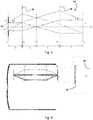
- Figure 3represents an example of an objective of a measuring device that may be used to shift the pupil entrance of the measuring device.
- the objective 30comprises an objective entrance pupil not represented in plan ⁇ 1 , an objective exit pupil 34 in plan ⁇ 5 , a first positive lens 36 having a first focal distance in plan ⁇ 2 and a second positive lens 38 in plan ⁇ 4 , having a second focal distance.
- the objective entrance pupil, the first and second positive lenses and the exit pupilare placed along a common optical axis, with a distance between the entrance pupil and the first positive lens equal to the focal distance of the first positive lens, a distance between the first positive lens and the second positive lens equal to the addition of the focal distances of the first and second optical lenses, and the distance between the exit pupil and the second positive lens equal to the focal distance of the second positive lens.
- the afocal objective 30allows moving the entrance pupil upstream of its structure.
- the afocal objective entrance pupil of the optical measurement device in plan ⁇ 5is moved upstream to plan ⁇ 1 .
- An advantage of this type of moduleis particularly the small diameter of the optical lenses allowing a tubular shape particularly appropriate for measuring head mounted display device mounted in a spectacle frame.
- Figure 4illustrates an example of measuring device provided with a shift element whose exit pupil is shifted about 20cm upstream Pe.
- the blockhas a diameter of about 30mm, which allows our characterizations on most type of head mounted display devices.
- the shift elementmay be afocal or pseudo afocal, and optionally contain one or more mirrors.
- the set of optical lensescan have one or more aspherical surfaces so as to maximize the optical performance of the overall element.
- the shift elementis preferably at least 15cm long so as to be longer than most spectacle frame temple.
- At least one optical performance parameter of the head mounted see-through display deviceis determined based on the data measured by the optical measurement device during the optical performance determining step S6.
- the head mounted display deviceis configured so that the display images are seen by the wearer through an optical lens having a dioptric function.
- an optical lens having a dioptric functionis to be understood as having a deviation effect on the light beams coming from the display.
- the optical lens having a dioptric functionmay not be removed from the head mounted device when implementing the method of the invention.
- the dioptric functionmay make it very difficult or even impossible to measure accurately the optical performance parameter. In particular it may make it difficult for the measuring device to correctly focus on the displayed image, in particular if the dioptric function comprises astigmatism.
- the method of the inventionfurther comprises prior to the positioning step a compensation optical element providing step S4.
- an optical element having a dioptric function adapted to compensate the dioptric function of the optical lens having a dioptric functionis provided between the optical lens having a dioptric function and the entrance pupil of the optical measurement device.
- the effect of the dioptric function of the optical lens of the head mounted display devicemay be compensated and from the point of view of the optical measurement device the displayed image is seen as if the optical lens has no dioptric function.
- the optical element adapted to compensate the dioptric functionmay comprise a set of optical lenses provided between the display device and the pupil of the optical measurement device.
- the optical element adapted to compensate the dioptric functionmay comprises an optical lens provided on the pupil of the optical measurement device.
- An active optical lensmay further be used to compensate the dioptric function, for example a liquid-crystal electronically driven lenses, or fluid-filled or Alvarez lenses.
- the method of the inventionmay further comprise prior to the positioning step an immersion step S4.
- the optical element having a dioptric functionis immerged in a medium having a refractive index deferring by less than 0.05, for example less than 0.01, from the refractive index of the optical lens having a dioptric function.
- a transparent wafer having two opposed parallel surfacesis positioned on one or both surfaces of the optical lens having a dioptric function.
- parallelmeans having parallel tangent at each point of the surface.
- the gap between the surface of the optical lens and the transparent waferbeing filled with a transparent liquid having a refractive index deferring by less than 0.05, for example by less than 0.01, from the refractive index of the optical lens having a dioptric function.
- the transparent waferis placed as close as possible from the front or rear surface of the optical lens having a dioptric function, for example in contact with at least a point of the front or rear surface of the optical lens having a dioptric function.
- Figure 5illustrates an example of an embodiment of the invention where an immersion device is used to compensate the dioptric function.
- bi-plane transparent mineral plat 50preferably with antireflection coating in the visible spectrum, is mounted parallel to the surfaces of the optical insert 16 adapted for displaying the virtual image.
- the mineral plat 50allows compress a seal against the optical lens 52 having a dioptric function.
- the sealed tank between the mineral plat 50 and the optical lens 52is filled with liquid having a refractive index deferring by less than 0.05, for example by less than 0.01, from the refractive index of the optical lens having a dioptric function.
- Having the mineral plat 50 parallel to the surfaces of the optical insert 16 surfaceprevents the appearance of prism during the measurement.
- the parallelismmay be ensured by placing the mineral plat 50 directly on the display device or via intermediate pieces.
- the devicewould need to be adapted so that both surfaces of the mineral plate have exactly the same non-planar shape.
- the requirementis that firstly the space between the front face of the wafer, that is the rear surface 20 of the light-guide optical element 16 if not considering the adhesive thickness and the liquid has a constant thickness, and secondly the optical plate has a constant thickness.
- This disclosuremay further refer to a method of assembling a head mounted display device adapted for a wearer.
- Such methodmay comprise a relative position adapting step during which the relative position of the display device and the rest of the head mounted device is adapted while measuring an optical performance parameter of the head mounted display device using a method according to the invention, so as to optimize an optical performance parameter of the wearer.
- optical performance parameterthat may be measured one can consider:
- This disclosuremay further relate to a method of assembling a head mounted display device adapted for a wearer and configured so that the display images are seen by the wearer though an optical lens having a dioptric function.
- Such methodmay comprise a relative position adapting step during which the relative position of the display device and the rest of the head mounted device, for example the optical lens having a dioptric function, is adapted while having a compensation optical element provided between the optical lens of the head mounted display device and the entrance pupil of an optical measurement device, so as to compensate the dioptric function of the optical lens having a dioptric function.
- the mounted sensing deviceis not limited to a head mounted device.
Landscapes
- Physics & Mathematics (AREA)
- General Physics & Mathematics (AREA)
- Optics & Photonics (AREA)
- Spectroscopy & Molecular Physics (AREA)
- Engineering & Computer Science (AREA)
- Computer Vision & Pattern Recognition (AREA)
- Theoretical Computer Science (AREA)
- Geometry (AREA)
- Chemical & Material Sciences (AREA)
- Analytical Chemistry (AREA)
- Astronomy & Astrophysics (AREA)
- Eyeglasses (AREA)
Description
- The invention relates to a method for determining an optical performance parameter of a head mounted display device adapted for a wearer and a method of assembling a head mounted display device adapted for a wearer.
- The invention further relates to imaging photo-colorimeter having a pupil shift element.
- Head mounted display devices are becoming more and more popular. Such type of device usually comprise a display element adapted to display images to the wearer of the head mounted device. Examples of such head mounter display devices are disclosed in
WO 2007/125257 A1 ,JP 2006 203440 A WO 2007/048929 A1 and Gabbard Joseph L et al. - There is a need to provide a method for determining the optical performances of such display devices.
- Imagining photo-colorimeters also called videocolorimeters are frequently used to determine the color response of display devices such as computer or television screens.
- However, unlike most display devices, such as computer or television screens, head mounted display devices are very position sensitive. In particular the optical performances of head mounted devices are very sensitive to the position relative to the eye of the wearer. Furthermore, the configuration of most of the head mounted display devices makes the positioning of the measuring device such as imagining photo-calorimeters complex.
- Therefore, there is need for a method for determining optical parameters of a head mounted display device.
- One object of the present invention is to provide such a method.
- To this end, the invention proposes a method for determining an optical performance parameter of a head mounted display device as defined in claim 1.
- Advantageously, the method of the invention allows increasing the quality of the measurements of the optical performance parameters of the head mounted device.
- Indeed, the inventors have observed that positioning the optical measurement device and the head mounted display device so that the position of the entrance pupil of the optical measurement device corresponds to the position of the pupil of the wearer when wearing the head mounted display device significantly increases the accuracy of the measurements obtained by the measuring device.
- According to further embodiments which can be considered alone or in combination:
- the method further comprises prior to the positioning step, a pupil moving element providing step during which a pupil moving element configured to move the entrance pupil of the optical measurement device is provided and during the positioning step the pupil shift element is configured so as to shift the entrance pupil of the optical measurement device to the position of the pupil of the wearer when wearing the head mounted display device; and/or
- the pupil moving element is a pupil shift element configured to shift the entrance pupil of the optical measurement device; and/or
- the entrance pupil of the measuring device and/or of the pupil shift element has/have a diameter greater than or equal to 2 mm and smaller than or equal to 10 mm; and/or
- the pupil shift element comprises an objective configured to have a focus range between 25 cm and infinity; and/or
- the objective comprises an objective entrance pupil, an objective exit pupil, a first positive lens having a first focal distance and a second positive lens having a second focal distance, the objective entrance pupil, the first and second positive lenses and the exit pupil being placed along a common optical axis, with a distance between the entrance pupil and the first positive lens equal to the focal distance of the first positive lens, a distance between the first positive lens and the second positive lens equal to the addition of the focal distances of the first and second optical lenses, and the distance between the exit pupil and the second positive lens equal to the focal distance of the second positive lens; and/or
- the optical magnification of the objective is equal to -1; and/or
- the optical measurement device is an imaging photo-colorimeter; and/or
- the head mounted display device is mounted in a spectacle frame; and/or
- the head mounted display device is a see-through head mounted display device; and/or
- the head mounted display device is configured so that the display images are seen by the wearer through an optical lens having a dioptric function, and the method further comprises prior to the positioning step an immersion step during which the optical element having a dioptric function is immerged in a medium having a refractive index deferring by less than 0.05, for example less than 0.01, from the refractive index of the optical lens having a dioptric function; and/or
- during the immersion step a transparent wafer having two opposed parallel surfaces is positioned on one or both surfaces of the optical lens having a dioptric function, the gap between the surface of the optical lens and the transparent wafer being filled with a transparent liquid having a refractive index deferring by less than 0.05, for example by less than 0.01, from the refractive index of the optical lens having a dioptric function; and/or
- the space between the front face of the wafer and the liquid has a constant thickness, and the optical plate has a constant thickness; and/or
- the transparent wafer is placed as close as possible from the front or rear surface of the optical lens having a dioptric function, for example in contact with at least a point of the front or rear surface of the optical lens having a dioptric function.
- Embodiments of the invention will now be described, by way of example only, and with reference to the following drawings in which:
Figure 1 is a flowchart of a method according to the invention,Figure 2 is a schematic representation of a head mounted display device,Figure 3 is a schematic representation of a shift element of the invention,figure 4 illustrates a measuring step of a method of the invention, andfigure 5 illustrates an immersion step of a method of the invention.- Elements in the figures are illustrated for simplicity and clarity and have not necessarily been drawn to scale. For example, the dimensions of some of the elements in the figure may be exaggerated relative to other elements to help improve the understanding of the embodiments of the present invention.
- The invention relates to a method for determining an optical performance parameter of a head mounted display device adapted for a wearer.
- As illustrated on
figure 1 , the method of the invention comprises at least: - head mounted display device providing step S1,
- an optical measurement device providing step S2,
- a positioning step S5, and
- an optical performance parameter determining step S6.
- A head mounted device adapted for a wearer is provided during the head mounted display device providing step S1.
- An example of head mounted display device is illustrated on
figure 2 . - A head mounted device may comprise a virtual image display device, preferably allowing the wearer to see both the virtual image and the real world through it.
- An example of see-through display system is illustrated in
figure 2 . Such see-trough display system comprises adisplay source 11, acollimating device 13, and anoptical insert 16 constituted by a light-guide optical element 16 (LOE). - The
display source 11 can be emissive or not emissive. - The light-guide
optical element 16 typically includes at least twomajor surfaces surface 24 and anoptical element 26 for coupling light thereinto. Theoutput waves 18 from thecollimating device 13 enter the light-guideoptical element 16 through itslower surface 20. The incoming waves (towards the light-guide optical element 16) are reflected from thesurface 26 and trapped in the light-guideoptical element 16. - In an embodiment, the electro-optical system may comprise a plane light-guide
optical element 16 with at least two planarmajor surfaces - In an alternative embodiment, the electro-optical system may comprise a curved light-guide
optical element 16. - The light-guide may be encapsulated in an optical lens, for example inserted laterally in a slot of the optical lens or by stacking in close contact the light-guide with at least one substrate of the optical lens and made integral with an adhesive.
- The light-guide may also be placed in front of an optical lens. The head mounted device may be a see-through head mounted display device.
- Although not represented on
figure 2 , the head mounted device may be mounted in a spectacle frame. - An optical measurement device is provided during the optical measurement device providing step S2. The optical measurement device comprises at least an entrance pupil Pe and a
sensor 28 receiving light through the entrance pupil. - The optical measurement device may be an imaging photo-colorimeter.
- Such optical measurement device allows recovering at any pixel in an acquired image a photocolorimetric parameter corresponding to a color sensation. Imaging photo-colorimeter usually comprise an objective adapted to focus over a given range of distances, a sensor and a
wheel filter 29 to link acquisitions by the device to colorful sensations perceived by the human eye. - Usually, this type of measuring device, is used for characterizing the quality of screen display such a computer or TV screens. In such cases, the imaging photo-colorimeter is placed in front of the screen. However, the relative position of the imaging photo-colorimeter and the screen has very little importance as long as the screen is in focus, unlike when determining the optical performance of a head mounted device.
- Indeed, in the case of a head mounted display determining the optical performance of the display device without knowledge of the position of the wearer's pupil when wearing the display device provides poor accuracy determination.
- Therefore, during the positioning step S5, the optical measurement device and the head mounted display device are positioned so that the position of the entrance pupil of the optical measurement device corresponds to the position of the pupil of the wearer when wearing the head mounted display device.
- Advantageously, positioning the entrance pupil of the optical measurement device so as to correspond to the position of the pupil of the wearer when wearing the head mounted display device increases the accuracy of the determination of the optical parameters.
- During the positioning step the relative position of the entrance pupil of the optical measurement device and the head mounted display device may comprise adapting the position in translation and in rotation.
- If the head mounted device comprises an optical lens, the positioning step may comprise the optical lens orientation, for example the pantoscopic or wrap angles relative to the pupil of the eye so as to correspond to a given gazing direction, such as straight ahead.
- When determining the optical performance of a head mounted device space may be an issue. In particular when positioning the optical measurement device so as to have the entrance pupil correspond to the position of the pupil of the wearer part of the measuring device may interfere with part of the head mounted device, for example part of the spectacle frame.
- Indeed, for some configuration of the head mounted display devices the spectacle frame comprise part of the electronic element required to display an image. Therefore, it may not be possible to remove the spectacle frame, in particular the temple of the spectacle frame.
- To overcome such arrangement issue, the method of the invention may comprise prior to the positioning step, a pupil shift element providing step S3.
- During the pupil shift element providing step a pupil shift element configured to shift the entrance pupil of the optical measurement device is provided.
- During the positioning step the pupil shift element is configured so as to shift the entrance pupil of the optical measurement device to the position of the pupil of the wearer when wearing the head mounted display device.
- The shift element may further be configured to allow orienting the entrance pupil of the optical measurement device relative to the display device.
- According to an embodiment of the invention, the entrance pupil of the measuring device and/or of the pupil shift element has/have a diameter greater than or equal to 2 mm and smaller than or equal to 10 mm. Advantageously, such diameter being close to the one of the pupil of the wearer, the optical parameter determined using the method of the invention more accurately corresponds to the optical parameter perceived by the wearer.
- Furthermore, the measuring device may have a range of accommodation at least equal to that of a standard wearer, for example between 25cm and infinity allowing to have the measuring device focus of the images displayed by the head mounted display device that is usually displayed at a position between a few meters and infinity.
Figure 3 represents an example of an objective of a measuring device that may be used to shift the pupil entrance of the measuring device.- The objective 30 comprises an objective entrance pupil not represented in plan π1, an
objective exit pupil 34 in plan π5, a firstpositive lens 36 having a first focal distance in plan π2 and a secondpositive lens 38 in plan π4, having a second focal distance. - The objective entrance pupil, the first and second positive lenses and the exit pupil are placed along a common optical axis, with a distance between the entrance pupil and the first positive lens equal to the focal distance of the first positive lens, a distance between the first positive lens and the second positive lens equal to the addition of the focal distances of the first and second optical lenses, and the distance between the exit pupil and the second positive lens equal to the focal distance of the second positive lens.
- The afocal objective 30 allows moving the entrance pupil upstream of its structure. The afocal objective entrance pupil of the optical measurement device in plan π5 is moved upstream to plan π1.
- An advantage of this type of module is particularly the small diameter of the optical lenses allowing a tubular shape particularly appropriate for measuring head mounted display device mounted in a spectacle frame.
- A further advantage of the objective illustrated on
figure 3 is to allow applying an angular magnification term γ = - f2 / f1 in the field of the scene with f1 and f2 the focal distances of the optical lenses. So if the acquisition system has an angle of view of β, the same system with the objective illustrated onfigure 3 has an angle of view α of β / | γ |. Figure 4 illustrates an example of measuring device provided with a shift element whose exit pupil is shifted about 20cm upstream Pe.- In this case γ = -1. The block has a diameter of about 30mm, which allows our characterizations on most type of head mounted display devices.
- The shift element may be afocal or pseudo afocal, and optionally contain one or more mirrors. The set of optical lenses can have one or more aspherical surfaces so as to maximize the optical performance of the overall element. The shift element is preferably at least 15cm long so as to be longer than most spectacle frame temple.
- At least one optical performance parameter of the head mounted see-through display device is determined based on the data measured by the optical measurement device during the optical performance determining step S6.
- According to the invention, the head mounted display device is configured so that the display images are seen by the wearer through an optical lens having a dioptric function.
- In the sense of the invention an optical lens having a dioptric function is to be understood as having a deviation effect on the light beams coming from the display.
- In some specific configurations the optical lens having a dioptric function may not be removed from the head mounted device when implementing the method of the invention. The dioptric function may make it very difficult or even impossible to measure accurately the optical performance parameter. In particular it may make it difficult for the measuring device to correctly focus on the displayed image, in particular if the dioptric function comprises astigmatism.
- Therefore, as illustrated on
figure 1 , the method of the invention further comprises prior to the positioning step a compensation optical element providing step S4. - During the compensation optical element providing step S4 an optical element having a dioptric function adapted to compensate the dioptric function of the optical lens having a dioptric function is provided between the optical lens having a dioptric function and the entrance pupil of the optical measurement device.
- Advantageously the effect of the dioptric function of the optical lens of the head mounted display device may be compensated and from the point of view of the optical measurement device the displayed image is seen as if the optical lens has no dioptric function.
- The optical element adapted to compensate the dioptric function may comprise a set of optical lenses provided between the display device and the pupil of the optical measurement device.
- The optical element adapted to compensate the dioptric function may comprises an optical lens provided on the pupil of the optical measurement device.
- An active optical lens may further be used to compensate the dioptric function, for example a liquid-crystal electronically driven lenses, or fluid-filled or Alvarez lenses.
- The method of the invention may further comprise prior to the positioning step an immersion step S4.
- During the immersion step, the optical element having a dioptric function is immerged in a medium having a refractive index deferring by less than 0.05, for example less than 0.01, from the refractive index of the optical lens having a dioptric function.
- For example, during the immersion step a transparent wafer having two opposed parallel surfaces is positioned on one or both surfaces of the optical lens having a dioptric function.
- In the sense of the invention parallel means having parallel tangent at each point of the surface.
- The gap between the surface of the optical lens and the transparent wafer being filled with a transparent liquid having a refractive index deferring by less than 0.05, for example by less than 0.01, from the refractive index of the optical lens having a dioptric function.
- Preferably, the transparent wafer is placed as close as possible from the front or rear surface of the optical lens having a dioptric function, for example in contact with at least a point of the front or rear surface of the optical lens having a dioptric function.
Figure 5 illustrates an example of an embodiment of the invention where an immersion device is used to compensate the dioptric function.- As shown bi-plane
transparent mineral plat 50, preferably with antireflection coating in the visible spectrum, is mounted parallel to the surfaces of theoptical insert 16 adapted for displaying the virtual image. - The
mineral plat 50 allows compress a seal against theoptical lens 52 having a dioptric function. - The sealed tank between the
mineral plat 50 and theoptical lens 52 is filled with liquid having a refractive index deferring by less than 0.05, for example by less than 0.01, from the refractive index of the optical lens having a dioptric function. - Advantageously this will remove the optical interface between the optical lens having the dioptric function and the air and temporarily compensate for the dioptric function.
- Having the
mineral plat 50 parallel to the surfaces of theoptical insert 16 surface prevents the appearance of prism during the measurement. The parallelism may be ensured by placing themineral plat 50 directly on the display device or via intermediate pieces. - If the surface of the optical insert has a none flat shape, the device would need to be adapted so that both surfaces of the mineral plate have exactly the same non-planar shape. The requirement is that firstly the space between the front face of the wafer, that is the
rear surface 20 of the light-guideoptical element 16 if not considering the adhesive thickness and the liquid has a constant thickness, and secondly the optical plate has a constant thickness. - This disclosure may further refer to a method of assembling a head mounted display device adapted for a wearer. Such method may comprise a relative position adapting step during which the relative position of the display device and the rest of the head mounted device is adapted while measuring an optical performance parameter of the head mounted display device using a method according to the invention, so as to optimize an optical performance parameter of the wearer.
- Among the optical performance parameter that may be measured one can consider:
- the uniformity of color in the image field: one can for example verify the chromaticity coordinates of a given color remain constant throughout the field, and/or
- the lack of image duplication, particularly when using a waveguide type Lumus when the output image is not perfectly collimated, and/or
- the distortion of the image, which can be observed via the deformation of a grid.
- This disclosure may further relate to a method of assembling a head mounted display device adapted for a wearer and configured so that the display images are seen by the wearer though an optical lens having a dioptric function.
- Such method may comprise a relative position adapting step during which the relative position of the display device and the rest of the head mounted device, for example the optical lens having a dioptric function, is adapted while having a compensation optical element provided between the optical lens of the head mounted display device and the entrance pupil of an optical measurement device, so as to compensate the dioptric function of the optical lens having a dioptric function.
- The invention has been described above with the aid of embodiments without limitation of the general inventive concept; in particular the mounted sensing device is not limited to a head mounted device.
- Many further modifications and variations will suggest themselves to those skilled in the art upon making reference to the foregoing illustrative embodiments, which are given by way of example only and which are not intended to limit the scope of the invention, that being determined solely by the appended claims.
- In the claims, the word "comprising" does not exclude other elements or steps, and the indefinite article "a" or "an" does not exclude a plurality. The mere fact that different features are recited in mutually different dependent claims does not indicate that a combination of these features cannot be advantageously used. Any reference signs in the claims should not be construed as limiting the scope of the invention.
Claims (12)
- Method for determining an optical performance parameter of a head mounted display device adapted for a wearer, the head mounted display device being configured so that display images are seen by the wearer through an optical lens having a dioptric function, the method comprising at least:- a head mounted display device providing step S1, during which a head mounted display device adapted for a wearer is provided,- an optical measurement device providing step S2, during which an optical measurement device is provided, the optical measurement device comprises at least an entrance pupil (Pe) and a sensor (28) receiving light through the entrance pupil,- a compensation optical element providing step during which an optical element having a dioptric function adapted to compensate the dioptric function of the optical lens having a dioptric function is provided between the optical lens having a dioptric function and the entrance pupil of the optical measurement device,- a positioning step S5, during which the optical measurement device and the head mounted display device are positioned so that the position of the entrance pupil of the optical measurement device corresponds to the position of the pupil of the wearer when wearing the head mounted display device,- an optical performance parameter determining step S6 during which at least one optical performance parameter of the head mounted see-through display device is determined based on the data measured by the optical measurement device.
- The method according to claim 1, further comprising prior to the positioning step, a pupil shift element providing step during which a pupil shift element configured to shift the entrance pupil of the optical measurement device is provided and during the positioning step the pupil shift element is configured so as to shift the entrance pupil of the optical measurement device to the position of the pupil of the wearer when wearing the head mounted display device.
- The method according to any of claims 1 or 2, wherein the entrance pupil (Pe) of the measuring device and/or of the pupil shift element has/have a diameter greater than or equal to 2 mm and smaller than or equal to 10 mm.
- The method according to claim 1 or 3, wherein the pupil shift element comprises an objective (30) configured to have a focus range between 25 cm and infinity.
- The method according to claim 4, wherein the objective (30) comprises an objective entrance pupil, an objective exit pupil, a first positive lens (36) having a first focal distance and a second positive lens (38) having a second focal distance, the objective entrance pupil, the first and second positive lenses and the exit pupil being placed along a common optical axis, with a distance between the entrance pupil and the first positive lens equal to the focal distance of the first positive lens, a distance between the first positive lens and the second positive lens equal to the addition of the focal distances of the first and second optical lenses, and the distance between the exit pupil and the second positive lens equal to the focal distance of the second positive lens.
- The method according to claim 4 or 5, wherein the optical magnification of the objective is equal to -1.
- The method according to any of the preceding claims, wherein the optical measurement device is an imaging photo-colorimeter.
- The method according to any of the preceding claims, wherein head mounted display device is mounted in a spectacle frame.
- The method according to any of the preceding claims, wherein head mounted display device is a see-through head mounted display device.
- The method according to any of the preceding claims, wherein the compensation optical element providing step comprises an immersion step S4 during which the optical element having a dioptric function is immerged in a medium having a refractive index deferring by less than 0.05, for example less than 0.01, from the refractive index of the optical lens having a dioptric function.
- The method according to claim 10, wherein during the immersion step S4 a transparent wafer having two opposed parallel surfaces is positioned on one or both surfaces of the optical lens having a dioptric function, the gap between the surface of the optical lens and the transparent wafer being filled with a transparent liquid having a refractive index deferring by less than 0.05, for example by less than 0.01, from the refractive index of the optical lens having a dioptric function.
- The method according to claim 11, wherein the transparent wafer is placed as close as possible from the front or rear surface of the optical lens having a dioptric function, for example in contact with at least a point of the front or rear surface of the optical lens having a dioptric function.
Priority Applications (3)
| Application Number | Priority Date | Filing Date | Title |
|---|---|---|---|
| EP16306447.0AEP3318915B1 (en) | 2016-11-04 | 2016-11-04 | Method for determining an optical performance of a head mounted display device |
| CN201711037868.9ACN108020921B (en) | 2016-11-04 | 2017-10-30 | Method for determining optical performance of head-mounted display device |
| US15/797,818US10466107B2 (en) | 2016-11-04 | 2017-10-30 | Method for determining an optical performance of a head mounted display device |
Applications Claiming Priority (1)
| Application Number | Priority Date | Filing Date | Title |
|---|---|---|---|
| EP16306447.0AEP3318915B1 (en) | 2016-11-04 | 2016-11-04 | Method for determining an optical performance of a head mounted display device |
Publications (2)
| Publication Number | Publication Date |
|---|---|
| EP3318915A1 EP3318915A1 (en) | 2018-05-09 |
| EP3318915B1true EP3318915B1 (en) | 2020-04-22 |
Family
ID=57286427
Family Applications (1)
| Application Number | Title | Priority Date | Filing Date |
|---|---|---|---|
| EP16306447.0AActiveEP3318915B1 (en) | 2016-11-04 | 2016-11-04 | Method for determining an optical performance of a head mounted display device |
Country Status (3)
| Country | Link |
|---|---|
| US (1) | US10466107B2 (en) |
| EP (1) | EP3318915B1 (en) |
| CN (1) | CN108020921B (en) |
Families Citing this family (8)
| Publication number | Priority date | Publication date | Assignee | Title |
|---|---|---|---|---|
| GB201517607D0 (en)* | 2015-10-06 | 2015-11-18 | Silver Joshua D | Novel optical waveguide display |
| US10402950B1 (en) | 2016-11-15 | 2019-09-03 | Facebook Technologies, Llc | Optical measurement system |
| WO2020069420A2 (en) | 2018-09-28 | 2020-04-02 | Ocelot Laboratories Llc | Camera system |
| US11187914B2 (en) | 2018-09-28 | 2021-11-30 | Apple Inc. | Mirror-based scene cameras |
| EP3686767B1 (en)* | 2019-01-25 | 2024-05-22 | Essilor International | Method, device and system for identifying a device |
| WO2023123443A1 (en)* | 2021-12-31 | 2023-07-06 | 歌尔光学科技有限公司 | Detection lens for head-mounted display device, and detection method |
| CN115876446A (en)* | 2023-02-10 | 2023-03-31 | 武汉加特林光学仪器有限公司 | Detection device and method suitable for near-to-eye display products with different diopters |
| EP4575447A1 (en) | 2023-12-19 | 2025-06-25 | Essilor International | Compensation mechanism for measuring an image quality parameter for an eyepiece |
Family Cites Families (8)
| Publication number | Priority date | Publication date | Assignee | Title |
|---|---|---|---|---|
| US5731902A (en)* | 1996-08-19 | 1998-03-24 | Delco Electronics Corporation | Head-up display combiner binocular test fixture |
| JP2006203440A (en)* | 2005-01-19 | 2006-08-03 | Konica Minolta Photo Imaging Inc | External field light transmission type head mount display |
| FR2892588B3 (en)* | 2005-10-25 | 2008-01-25 | Tietronix Optics Soc Par Actio | GENERIC ANTI-GLARE SURVEILLANCE CAMERA |
| FR2900475B1 (en)* | 2006-04-26 | 2008-10-31 | Essilor Int | DISPLAY COMPRISING A PAIR OF BINOCULAR GLASSES AND WITH A DEVICE FOR ADJUSTING THE IMAGE |
| US8802000B2 (en)* | 2008-08-01 | 2014-08-12 | Bio-Rad Laboratories, Inc. | Microplates with ultra-thin walls by two-stage forming |
| US20150277841A1 (en)* | 2014-03-27 | 2015-10-01 | Microsoft Corporation | Multi mode display system |
| WO2016191950A1 (en)* | 2015-05-29 | 2016-12-08 | 深圳市柔宇科技有限公司 | Display adjustment method and head-mounted display device |
| CN205581421U (en)* | 2016-05-07 | 2016-09-14 | 杭州映墨科技有限公司 | Wear -type virtual reality optical system of diopter is adjusted with fei nieer lens |
- 2016
- 2016-11-04EPEP16306447.0Apatent/EP3318915B1/enactiveActive
- 2017
- 2017-10-30CNCN201711037868.9Apatent/CN108020921B/enactiveActive
- 2017-10-30USUS15/797,818patent/US10466107B2/enactiveActive
Non-Patent Citations (1)
| Title |
|---|
| None* |
Also Published As
| Publication number | Publication date |
|---|---|
| CN108020921B (en) | 2021-01-26 |
| CN108020921A (en) | 2018-05-11 |
| EP3318915A1 (en) | 2018-05-09 |
| US20180128685A1 (en) | 2018-05-10 |
| US10466107B2 (en) | 2019-11-05 |
Similar Documents
| Publication | Publication Date | Title |
|---|---|---|
| EP3318915B1 (en) | Method for determining an optical performance of a head mounted display device | |
| US11500217B2 (en) | Pancake lens assembly and optical system thereof | |
| US10935804B1 (en) | Optical structure comprising a plurality of stacked optical elements that receive light having a first polarization and output light having a second polarization to a focal point | |
| US11022835B2 (en) | Optical system using segmented phase profile liquid crystal lenses | |
| EP3963387B1 (en) | Achromatic optical lens assembly having pancharatnam berry phase lens | |
| CN108713159B (en) | Curvature of field correction display | |
| US10609364B2 (en) | Pupil swim corrected lens for head mounted display | |
| JP2021532393A (en) | Reflective circular polarizing element for head-mounted display | |
| WO2020013829A1 (en) | Adaptive lenses for near-eye displays | |
| CN103439793B (en) | A kind of head-wearing display device HMD | |
| CN104950443A (en) | Light guide unit, image display device, and display apparatus | |
| EP3617772B1 (en) | Display system and image displaying method | |
| US20180046059A1 (en) | Display spectacles and driving method thereof | |
| US11567326B1 (en) | Accommodation bifocal optical assembly and optical system including same | |
| EP4460721A1 (en) | Display systems with collection optics for disparity sensing detectors | |
| CN202057928U (en) | Novel three-dimensional display panel component | |
| US12335453B2 (en) | Detection, analysis and correction of disparities in a display system utilizing disparity sensing port | |
| US20230084541A1 (en) | Compact imaging optics using spatially located, free form optical components for distortion compensation and image clarity enhancement | |
| US20150338657A1 (en) | Display device | |
| TWI461794B (en) | Display module and display device applied with the same | |
| US20230244185A1 (en) | Phase plate and fabrication method for color-separated laser backlight in display systems | |
| US11513373B2 (en) | Anisotropic diffraction grating and waveguide | |
| US20240302697A1 (en) | Achromatic wave plates based on compound twisted and untwisted nematic liquid crystal polymer | |
| US20250208466A1 (en) | Light collimating film for liquid crystal display backlight | |
| US10712577B1 (en) | Electronically tunable polarizing beam splitter |
Legal Events
| Date | Code | Title | Description |
|---|---|---|---|
| PUAI | Public reference made under article 153(3) epc to a published international application that has entered the european phase | Free format text:ORIGINAL CODE: 0009012 | |
| STAA | Information on the status of an ep patent application or granted ep patent | Free format text:STATUS: THE APPLICATION HAS BEEN PUBLISHED | |
| AK | Designated contracting states | Kind code of ref document:A1 Designated state(s):AL AT BE BG CH CY CZ DE DK EE ES FI FR GB GR HR HU IE IS IT LI LT LU LV MC MK MT NL NO PL PT RO RS SE SI SK SM TR | |
| AX | Request for extension of the european patent | Extension state:BA ME | |
| STAA | Information on the status of an ep patent application or granted ep patent | Free format text:STATUS: REQUEST FOR EXAMINATION WAS MADE | |
| 17P | Request for examination filed | Effective date:20181109 | |
| RBV | Designated contracting states (corrected) | Designated state(s):AL AT BE BG CH CY CZ DE DK EE ES FI FR GB GR HR HU IE IS IT LI LT LU LV MC MK MT NL NO PL PT RO RS SE SI SK SM TR | |
| STAA | Information on the status of an ep patent application or granted ep patent | Free format text:STATUS: EXAMINATION IS IN PROGRESS | |
| 17Q | First examination report despatched | Effective date:20190319 | |
| GRAP | Despatch of communication of intention to grant a patent | Free format text:ORIGINAL CODE: EPIDOSNIGR1 | |
| STAA | Information on the status of an ep patent application or granted ep patent | Free format text:STATUS: GRANT OF PATENT IS INTENDED | |
| INTG | Intention to grant announced | Effective date:20191115 | |
| GRAS | Grant fee paid | Free format text:ORIGINAL CODE: EPIDOSNIGR3 | |
| GRAA | (expected) grant | Free format text:ORIGINAL CODE: 0009210 | |
| STAA | Information on the status of an ep patent application or granted ep patent | Free format text:STATUS: THE PATENT HAS BEEN GRANTED | |
| AK | Designated contracting states | Kind code of ref document:B1 Designated state(s):AL AT BE BG CH CY CZ DE DK EE ES FI FR GB GR HR HU IE IS IT LI LT LU LV MC MK MT NL NO PL PT RO RS SE SI SK SM TR | |
| REG | Reference to a national code | Ref country code:CH Ref legal event code:EP | |
| REG | Reference to a national code | Ref country code:IE Ref legal event code:FG4D | |
| REG | Reference to a national code | Ref country code:DE Ref legal event code:R096 Ref document number:602016034446 Country of ref document:DE | |
| REG | Reference to a national code | Ref country code:AT Ref legal event code:REF Ref document number:1260893 Country of ref document:AT Kind code of ref document:T Effective date:20200515 | |
| REG | Reference to a national code | Ref country code:LT Ref legal event code:MG4D | |
| REG | Reference to a national code | Ref country code:NL Ref legal event code:MP Effective date:20200422 | |
| PG25 | Lapsed in a contracting state [announced via postgrant information from national office to epo] | Ref country code:NL Free format text:LAPSE BECAUSE OF FAILURE TO SUBMIT A TRANSLATION OF THE DESCRIPTION OR TO PAY THE FEE WITHIN THE PRESCRIBED TIME-LIMIT Effective date:20200422 Ref country code:PT Free format text:LAPSE BECAUSE OF FAILURE TO SUBMIT A TRANSLATION OF THE DESCRIPTION OR TO PAY THE FEE WITHIN THE PRESCRIBED TIME-LIMIT Effective date:20200824 Ref country code:SE Free format text:LAPSE BECAUSE OF FAILURE TO SUBMIT A TRANSLATION OF THE DESCRIPTION OR TO PAY THE FEE WITHIN THE PRESCRIBED TIME-LIMIT Effective date:20200422 Ref country code:GR Free format text:LAPSE BECAUSE OF FAILURE TO SUBMIT A TRANSLATION OF THE DESCRIPTION OR TO PAY THE FEE WITHIN THE PRESCRIBED TIME-LIMIT Effective date:20200723 Ref country code:LT Free format text:LAPSE BECAUSE OF FAILURE TO SUBMIT A TRANSLATION OF THE DESCRIPTION OR TO PAY THE FEE WITHIN THE PRESCRIBED TIME-LIMIT Effective date:20200422 Ref country code:IS Free format text:LAPSE BECAUSE OF FAILURE TO SUBMIT A TRANSLATION OF THE DESCRIPTION OR TO PAY THE FEE WITHIN THE PRESCRIBED TIME-LIMIT Effective date:20200822 Ref country code:NO Free format text:LAPSE BECAUSE OF FAILURE TO SUBMIT A TRANSLATION OF THE DESCRIPTION OR TO PAY THE FEE WITHIN THE PRESCRIBED TIME-LIMIT Effective date:20200722 Ref country code:FI Free format text:LAPSE BECAUSE OF FAILURE TO SUBMIT A TRANSLATION OF THE DESCRIPTION OR TO PAY THE FEE WITHIN THE PRESCRIBED TIME-LIMIT Effective date:20200422 | |
| REG | Reference to a national code | Ref country code:AT Ref legal event code:MK05 Ref document number:1260893 Country of ref document:AT Kind code of ref document:T Effective date:20200422 | |
| PG25 | Lapsed in a contracting state [announced via postgrant information from national office to epo] | Ref country code:LV Free format text:LAPSE BECAUSE OF FAILURE TO SUBMIT A TRANSLATION OF THE DESCRIPTION OR TO PAY THE FEE WITHIN THE PRESCRIBED TIME-LIMIT Effective date:20200422 Ref country code:HR Free format text:LAPSE BECAUSE OF FAILURE TO SUBMIT A TRANSLATION OF THE DESCRIPTION OR TO PAY THE FEE WITHIN THE PRESCRIBED TIME-LIMIT Effective date:20200422 Ref country code:RS Free format text:LAPSE BECAUSE OF FAILURE TO SUBMIT A TRANSLATION OF THE DESCRIPTION OR TO PAY THE FEE WITHIN THE PRESCRIBED TIME-LIMIT Effective date:20200422 Ref country code:BG Free format text:LAPSE BECAUSE OF FAILURE TO SUBMIT A TRANSLATION OF THE DESCRIPTION OR TO PAY THE FEE WITHIN THE PRESCRIBED TIME-LIMIT Effective date:20200722 | |
| PG25 | Lapsed in a contracting state [announced via postgrant information from national office to epo] | Ref country code:AL Free format text:LAPSE BECAUSE OF FAILURE TO SUBMIT A TRANSLATION OF THE DESCRIPTION OR TO PAY THE FEE WITHIN THE PRESCRIBED TIME-LIMIT Effective date:20200422 | |
| REG | Reference to a national code | Ref country code:DE Ref legal event code:R097 Ref document number:602016034446 Country of ref document:DE | |
| PG25 | Lapsed in a contracting state [announced via postgrant information from national office to epo] | Ref country code:CZ Free format text:LAPSE BECAUSE OF FAILURE TO SUBMIT A TRANSLATION OF THE DESCRIPTION OR TO PAY THE FEE WITHIN THE PRESCRIBED TIME-LIMIT Effective date:20200422 Ref country code:RO Free format text:LAPSE BECAUSE OF FAILURE TO SUBMIT A TRANSLATION OF THE DESCRIPTION OR TO PAY THE FEE WITHIN THE PRESCRIBED TIME-LIMIT Effective date:20200422 Ref country code:ES Free format text:LAPSE BECAUSE OF FAILURE TO SUBMIT A TRANSLATION OF THE DESCRIPTION OR TO PAY THE FEE WITHIN THE PRESCRIBED TIME-LIMIT Effective date:20200422 Ref country code:AT Free format text:LAPSE BECAUSE OF FAILURE TO SUBMIT A TRANSLATION OF THE DESCRIPTION OR TO PAY THE FEE WITHIN THE PRESCRIBED TIME-LIMIT Effective date:20200422 Ref country code:DK Free format text:LAPSE BECAUSE OF FAILURE TO SUBMIT A TRANSLATION OF THE DESCRIPTION OR TO PAY THE FEE WITHIN THE PRESCRIBED TIME-LIMIT Effective date:20200422 Ref country code:EE Free format text:LAPSE BECAUSE OF FAILURE TO SUBMIT A TRANSLATION OF THE DESCRIPTION OR TO PAY THE FEE WITHIN THE PRESCRIBED TIME-LIMIT Effective date:20200422 Ref country code:SM Free format text:LAPSE BECAUSE OF FAILURE TO SUBMIT A TRANSLATION OF THE DESCRIPTION OR TO PAY THE FEE WITHIN THE PRESCRIBED TIME-LIMIT Effective date:20200422 Ref country code:IT Free format text:LAPSE BECAUSE OF FAILURE TO SUBMIT A TRANSLATION OF THE DESCRIPTION OR TO PAY THE FEE WITHIN THE PRESCRIBED TIME-LIMIT Effective date:20200422 | |
| PG25 | Lapsed in a contracting state [announced via postgrant information from national office to epo] | Ref country code:SK Free format text:LAPSE BECAUSE OF FAILURE TO SUBMIT A TRANSLATION OF THE DESCRIPTION OR TO PAY THE FEE WITHIN THE PRESCRIBED TIME-LIMIT Effective date:20200422 Ref country code:PL Free format text:LAPSE BECAUSE OF FAILURE TO SUBMIT A TRANSLATION OF THE DESCRIPTION OR TO PAY THE FEE WITHIN THE PRESCRIBED TIME-LIMIT Effective date:20200422 | |
| PLBE | No opposition filed within time limit | Free format text:ORIGINAL CODE: 0009261 | |
| STAA | Information on the status of an ep patent application or granted ep patent | Free format text:STATUS: NO OPPOSITION FILED WITHIN TIME LIMIT | |
| 26N | No opposition filed | Effective date:20210125 | |
| PG25 | Lapsed in a contracting state [announced via postgrant information from national office to epo] | Ref country code:SI Free format text:LAPSE BECAUSE OF FAILURE TO SUBMIT A TRANSLATION OF THE DESCRIPTION OR TO PAY THE FEE WITHIN THE PRESCRIBED TIME-LIMIT Effective date:20200422 | |
| PG25 | Lapsed in a contracting state [announced via postgrant information from national office to epo] | Ref country code:MC Free format text:LAPSE BECAUSE OF FAILURE TO SUBMIT A TRANSLATION OF THE DESCRIPTION OR TO PAY THE FEE WITHIN THE PRESCRIBED TIME-LIMIT Effective date:20200422 | |
| REG | Reference to a national code | Ref country code:CH Ref legal event code:PL | |
| PG25 | Lapsed in a contracting state [announced via postgrant information from national office to epo] | Ref country code:LU Free format text:LAPSE BECAUSE OF NON-PAYMENT OF DUE FEES Effective date:20201104 | |
| REG | Reference to a national code | Ref country code:BE Ref legal event code:MM Effective date:20201130 | |
| PG25 | Lapsed in a contracting state [announced via postgrant information from national office to epo] | Ref country code:CH Free format text:LAPSE BECAUSE OF NON-PAYMENT OF DUE FEES Effective date:20201130 Ref country code:LI Free format text:LAPSE BECAUSE OF NON-PAYMENT OF DUE FEES Effective date:20201130 | |
| PG25 | Lapsed in a contracting state [announced via postgrant information from national office to epo] | Ref country code:IE Free format text:LAPSE BECAUSE OF NON-PAYMENT OF DUE FEES Effective date:20201104 | |
| PG25 | Lapsed in a contracting state [announced via postgrant information from national office to epo] | Ref country code:TR Free format text:LAPSE BECAUSE OF FAILURE TO SUBMIT A TRANSLATION OF THE DESCRIPTION OR TO PAY THE FEE WITHIN THE PRESCRIBED TIME-LIMIT Effective date:20200422 Ref country code:MT Free format text:LAPSE BECAUSE OF FAILURE TO SUBMIT A TRANSLATION OF THE DESCRIPTION OR TO PAY THE FEE WITHIN THE PRESCRIBED TIME-LIMIT Effective date:20200422 Ref country code:CY Free format text:LAPSE BECAUSE OF FAILURE TO SUBMIT A TRANSLATION OF THE DESCRIPTION OR TO PAY THE FEE WITHIN THE PRESCRIBED TIME-LIMIT Effective date:20200422 | |
| PG25 | Lapsed in a contracting state [announced via postgrant information from national office to epo] | Ref country code:MK Free format text:LAPSE BECAUSE OF FAILURE TO SUBMIT A TRANSLATION OF THE DESCRIPTION OR TO PAY THE FEE WITHIN THE PRESCRIBED TIME-LIMIT Effective date:20200422 | |
| PG25 | Lapsed in a contracting state [announced via postgrant information from national office to epo] | Ref country code:BE Free format text:LAPSE BECAUSE OF NON-PAYMENT OF DUE FEES Effective date:20201130 | |
| P01 | Opt-out of the competence of the unified patent court (upc) registered | Effective date:20230525 | |
| PGFP | Annual fee paid to national office [announced via postgrant information from national office to epo] | Ref country code:DE Payment date:20241127 Year of fee payment:9 | |
| PGFP | Annual fee paid to national office [announced via postgrant information from national office to epo] | Ref country code:GB Payment date:20241127 Year of fee payment:9 | |
| PGFP | Annual fee paid to national office [announced via postgrant information from national office to epo] | Ref country code:FR Payment date:20241126 Year of fee payment:9 |