EP3318208B1 - Distal radius fracture fixation plate with integrated and adjustable volar ulnar facet support - Google Patents
Distal radius fracture fixation plate with integrated and adjustable volar ulnar facet supportDownload PDFInfo
- Publication number
- EP3318208B1 EP3318208B1EP17153977.8AEP17153977AEP3318208B1EP 3318208 B1EP3318208 B1EP 3318208B1EP 17153977 AEP17153977 AEP 17153977AEP 3318208 B1EP3318208 B1EP 3318208B1
- Authority
- EP
- European Patent Office
- Prior art keywords
- holes
- bone
- head
- tabs
- tab
- Prior art date
- Legal status (The legal status is an assumption and is not a legal conclusion. Google has not performed a legal analysis and makes no representation as to the accuracy of the status listed.)
- Active
Links
Images


Classifications
- A—HUMAN NECESSITIES
- A61—MEDICAL OR VETERINARY SCIENCE; HYGIENE
- A61B—DIAGNOSIS; SURGERY; IDENTIFICATION
- A61B17/00—Surgical instruments, devices or methods
- A61B17/56—Surgical instruments or methods for treatment of bones or joints; Devices specially adapted therefor
- A61B17/58—Surgical instruments or methods for treatment of bones or joints; Devices specially adapted therefor for osteosynthesis, e.g. bone plates, screws or setting implements
- A61B17/68—Internal fixation devices, including fasteners and spinal fixators, even if a part thereof projects from the skin
- A61B17/80—Cortical plates, i.e. bone plates; Instruments for holding or positioning cortical plates, or for compressing bones attached to cortical plates
- A61B17/8061—Cortical plates, i.e. bone plates; Instruments for holding or positioning cortical plates, or for compressing bones attached to cortical plates specially adapted for particular bones
- A—HUMAN NECESSITIES
- A61—MEDICAL OR VETERINARY SCIENCE; HYGIENE
- A61B—DIAGNOSIS; SURGERY; IDENTIFICATION
- A61B17/00—Surgical instruments, devices or methods
- A61B17/56—Surgical instruments or methods for treatment of bones or joints; Devices specially adapted therefor
- A61B2017/564—Methods for bone or joint treatment
Definitions
- This inventionrelates broadly to surgical implants. More particularly, this invention relates to a bone fracture fixation system for distal radius fractures.
- Fracture to the metaphyseal portion of a long bonecan be difficult to treat. Improper treatment can result in deformity and long-term discomfort.
- a Colles' fractureis a fracture resulting from compressive forces being placed on the distal radius, and which causes backward or dorsal displacement of the distal fragment and radial deviation of the hand at the wrist.
- a Colles' fracturewill result in multiple bone fragments which are movable and out of alignment relative to each other. If not properly treated, such fractures may result in permanent wrist deformity and limited articulation of the wrist. It is therefore important to align the fracture and fixate the bones relative to each other so that proper healing may occur.
- Alignment and fixation of a metaphyseal fractureare typically performed by one of several methods: casting, external fixation, pinning, and plating.
- Castingis non-invasive, but may not be able to maintain alignment of the fracture where many bone fragments exist. Therefore, as an alternative, external fixators may be used.
- External fixatorsutilize a method known as ligamentotaxis, which provides distraction forces across the joint and permits the fracture to be aligned based upon the tension placed on the surrounding ligaments.
- ligamentotaxiswhich provides distraction forces across the joint and permits the fracture to be aligned based upon the tension placed on the surrounding ligaments.
- external fixatorscan maintain the position of the wrist bones, it may nevertheless be difficult in certain fractures to first provide the bones in proper alignment.
- external fixatorsare often not suitable for fractures resulting in multiple bone fragments.
- K-wiresKirschner wires
- Platingutilizes a stabilizing metal plate typically placed against the side of a bone, and screws extending from the plate into holes drilled in the bone fragments to provide stabilized fixation of the fragments.
- many currently available plate systemsfail to provide desirable alignment and stabilization.
- the distal radiusexhibits a concave shape extending from the shaft, which reaches an inflection point at a so-called watershed line followed by a convex like form at its most prominent feature, the volar rim.
- the complex shape of the distal radiusincluding the prominent volar rim of the lunate fossa, relatively flat volar rim of the scaphoid fossa, and the sometimes prominent base of the styloid process should be accommodated.
- the ligaments extending from the volar side of the distal radius to the intercarpal bonesmust not be irritated or distressed.
- a fixation deviceshould provide desirable alignment and stabilization of the bone structure proximate the articular surface of the distal radius.
- a volar platefor the distal radius that accommodates the anatomy.
- the plateincludes a head for placement at the metaphysis and a shaft for extension along the diaphysis.
- the head and shafteach include holes for receiving fasteners to couple the plate to the bone.
- the holes in the headare threaded fixed angle holes oriented to extend the shaft of the fasteners in a spatial distribution through the bone about the articular surface to provide significant support and early mobility.
- the top portions of the plateare such that they provide a buttress support for the fragment while providing a smooth contour to minimize soft tissue interaction and not creating a prominent sharp edge nearest the inflexion point or 'watershed line' of the volar rim.
- GB2477086describes a distal radius fixation system comprising a bone plate designed with three rows of screw holes which are in alignment. The radial side of the plate is curved backwards in comparison to the ulnar side with the distal most row of screw holes contoured backwards to capture the volar lip.
- volar ulnar facet fracturesoccur in the distal portion of the concave form of the distal radius and require additional fixation.
- the fracturesmay involve displaced avulsions, shear fractures and small fragments that are in the vicinity of the prominent portion of the volar rim.
- These fracturesare difficult to treat with existing hardware since most available hardware could interfere with surrounding soft tissue and/or increase the likelihood impinging on the articular surfaces of the distal radius.
- the present inventionrelates to a bone plate as defined in claim 1.
- a volar distal radius plateis provided having a shaft for placement on the diaphysis of the distal radius bone, and a head angled relative to the shaft and shaped for low profile placement on the metaphysis of the distal radius bone.
- the platehas a lower bone contacting surface and an opposite upper surface.
- the head of the plateis shaped to primarily seat below the boney crest inflexion point of the ⁇ watershed line' at the distal radius.
- the head and shafteach include holes for receiving fasteners to couple the plate to the bone.
- the holes in the headare threaded, fixed angle holes, arranged in two rows. The holes are oriented to extend screws in a spatial distribution through the bone and about the articular surface of the wrist socket to provide significant support.
- the threaded fixed angle holesare provided within the head to be located below the boney crest or watershed line of the distal radius.
- the radial side of the plateseats completely below the watershed line.
- the ulnar (or medial) side of the plateis provided with two smoothly contoured and chamfered distally extending tabs for extension over and beyond the watershed line when the plate is positioned on the bone.
- the tabsprovide a buttress support over the volar ulnar facet.
- the tabseach have a smoothly contoured upper surface that is adapted to be atraumatic to the soft tissue and thereby minimize soft tissue irritation.
- the tabscan be readily re-orientated to approximate the volar rim and provide close support.
- the tabsare provided with respective lower recesses, preferably as an undercut at the junction of the tabs and the remainder of the head plate; i.e., in a preferred embodiment, from the lower surface of the plate, the undercut and distal edge of the lateral side of the plate are in alignment.
- the recessesallow each tab to be contoured independently to fit the patient anatomy.
- Each tabis provided with a single hole specifically sized to closely receive a K-wire in a fixed angle orientation. This permits a K-wire to apply a bending load to a tab in situ to bend the tab about its lower recess into a new orientation to best match the patient anatomy and provide support. Therefore, the plate does not require a dedicated bender.
- the hole in each tabis spaced relative to the distal peripheral edge of the tab to accommodate passage of a suture needle completely therethrough.
- the plate 10for stabilization of a fracture of a distal radius bone 100 is shown.
- the plate 10includes a shaft 12 for placement on the diaphysis 102 of the distal radius bone 100, and a head 14 at a transverse orientation relative to the shaft for placement on the metaphysis 104.
- the plateincludes a bone contacting lower surface 16 and an opposite upper surface 18. The head is in angled upward relative to the shaft when the lower surface 16 of the shaft is positioned substantially horizontal and face down in contact with the diaphysis of the radius bone.
- the shaft 12 and head 14each include holes for receiving fasteners to couple the plate 10 to the bone 100.
- the shaft 12preferably includes a combination of compression holes 20, 22 and non-compression fixed angle, threaded holes 24.
- the compression holespreferably comprise both circular holes 20 and elongate slots 22.
- the holes 20, 22, 24comprise the system of holes described in co-owned and co-pending US Serial No. 13/313,350 , ( US 2013150901 Publication Number) filed December 7, 2011 .
- Holes of another design for suitable fastenersmay also be used; however, it is preferable that any provided holes and arrangement thereof include both circular holes and slots, and that such circular holes include a combination of compression holes for compression fasteners and fixed angled holes such as can accommodate a fastener with a threaded head in a fixed orientation.
- the platemay also include one of more K-wire holes 26 to closely receive respective K-wires for temporary fixation of the shaft 12 of the plate relative to the bone 100.
- the holes 28 in the head of the plate 14are threaded, fixed angle holes, with the threads of each hole defining a respective fixed axis for a fastener inserted therethrough.
- the threaded holes 28are preferably of a same configuration and size as the threaded holes 24, and thus capable of receiving and fixing a common fastener therewith.
- One exemplar fastener 150is shown in phantom in Fig. 2 .
- the holes 28are preferably arranged in two rows; a relatively proximal row 30 and a relatively distal row 32, the rows 30, 32 being acutely angled relative to each other.
- the proximal row 30 of holesincludes four threaded holes 28, and the distal row 32 includes three threaded holes 28 preferably arranged in an offset from the proximal row 30 such that the shafts of fasteners inserted in the proximal row 30 can extend distally between the shafts of the fasteners inserted in the distal row 32 in an interleaved manner. More preferably, when the plate is positioned on the bone at the intended location, the fasteners 150 extend into the bone in a spatial distribution about the articular surface 106 ( Fig. 4 ) of the wrist socket to provide subchondral support.
- All the threaded fixed angle holes 28 within the head 14 of the plateare provided to be located in the subchondral bone below the inflexion point of the watershed line (seen also in Fig. 6 ) on the volar side of the distal radius. Preferred locations of the threaded holes 28 relative to the volar distal radius and preferred axial orientations of such threaded holes are described in detail in US Pat. No. 7,294,130 .
- K-wire holesare also preferably provided relative to the threaded holes in the head of the plate.
- Two K-wire holes 34, 36are provided between respective sets of adjacent holes in the proximal row 30 of threaded holes.
- the K-wire holes 34, 36are sized to closely receive a K-wire such that an appropriately sized K-wire inserted therethrough is retained at a fixed angle relative to the plate 10 by the sidewalls of the respective K-wire hole.
- Such holescan be used for temporary fixation of the plate to the bone. Further, the K-wire, whether or not providing such temporary fixation, can be examined under fluoroscopy to analyze its trajectory relative to the bone anatomy and thereby provide information with respect to the apparent trajectory of fasteners through the adjacent threaded holes.
- an additional K-wire hole 38is preferably provided between two of the holes in the distal row 32.
- other small holes, such as 38can be provided to the head of the plate.
- Such other small holesmay be additional K-wire holes of the types described for the purpose of guiding a K-wire or the plate relative to the K-wire, or may be of the same or different structure so as to be otherwise adapted as anchor holes for suture to secure bone fragments and soft tissue relative to the plate.
- the radial side 40 of the plate 10is tapered to a distal edge 54 and sized and shaped to seat completely below the ⁇ watershed' inflexion line 108 of the boney crest.
- the ulnar (i.e., medial) side 42 of the distal edge of the plateis provided with two distally extending tabs 44, 46 separated from each other by a space 48. While the tabs 44, 46 extend from the ulnar (i.e., medial) side 42 of the distal edge, the tabs do not extend the lateral dimension of the head of the plate; the entire extension is preferably distal and displaced to the ulnar side.
- the tabs 44, 46extend approximately 5 mm beyond the distal end 54 of the plate such that the tabs 44, 46 extend beyond the ⁇ watershed' inflexion line of the distal radius bone when the plate is properly positioned on the bone in order to provide a support to the volar fragment, and particularly the ulnar facet 110 thereof ( Figs. 4 and 5 ). This allows the tabs 44, 46 to claw or buttress the volar fragment.
- the tabs 44, 46may be considered to be located as an ulnar side tab 44 and an intermediate tab 46, with 'intermediate' defining a location between the ulnar and radial sides of the distal radius when the plate is positioned on the volar side of the distal radius (and not a relative location between other tabs).
- the ulnar side tab 44is located distally in front of the medialmost (ulnar side) threaded hole 28a of the distal row 32 of threaded holes 28, and the intermediate tab 46 is located distally in front of the central threaded hole 28b of the distal row 32 of threaded holes 28 ( Fig.1 ).
- the tabs 44, 46each have a smoothly contoured and chamfered upper surface which tapers toward the medial side of the relatively ulnar side tab 44 and toward the lateral side of the intermediate tab 46. This provides the upper surface of the tabs 44, 46 with an atraumatic soft tissue contacting surface that minimizes soft tissue irritation.
- the lower surfaces 62 of the tabsare angled relative to the lower surface 60 at the remainder of the lower surface of the head 14. That is, while the remainder of the lower surface 60 of the head 14 is configured to seat in the concavity on the bone below the ⁇ watershed' inflexion line of the distal radius, the tabs 44, 46 are configured to extend over the watershed line and generally parallel to the volar rim 110.
- Angle Ais preferably between 26° and 30°.
- the tabs 44, 46can be readily re-orientated in situ to better approximate the volar rim 110 and provide close support to a fragment of the volar rim.
- Each tab 44, 46is provided with a single K-wire hole 56, 58 each defined by a cylindrical sidewall and specifically sized to closely receive a 1.6 mm K-wire in a fixed angle orientation.
- a fixed angle orientationis one in which the K-wire is retained coaxial with or within 5°, and more preferably within 3°, of the axis of the K-wire hole. With too much play between the K-wire and plate, the K-wire cannot positively engage the hole to provide accurate bending of the tabs in accord with the desired operation of the system.
- the holehas an approximate diameter of 1.6 mm to provide the necessary clearance for passage of the K-wire.
- the axes of the holes 56, 58 in the tabs 44, 46are oblique relative to the lower surface 16 at the tabs, as shown by angle ⁇ ( Fig. 2 ) and also seen in Fig. 3 .
- the tabs 44, 46are provided with respective lower recesses 50, 52 preferably formed as an undercut at the junction of the tabs and the remainder of the head of the plate; i.e., in a preferred embodiment, from the lower surface 16 of the plate, the recesses 50, 52 and distal edge 54 of the radial side 40 of the plate are in alignment.
- the recesses 50, 52reduce the cross-sectional area moment of inertia at the junction between the tabs 44, 46 and the remainder of the head 14 without requiring that the width of the tabs be reduced. That is, it is preferable that the junctions between the tabs and the remainder of the head are not reduced in the width (in a medial-lateral direction) relative to the respective tabs.
- the K-wire 200is able to apply a bending load to the tab 46 in situ to bend the tab about its lower recess 52, e.g., in the direction of arrow 202, into a new orientation to best match the patient anatomy and provide support for the ulnar facet of the volar rim 110. Therefore, the plate does not require a dedicated bender. Moreover, the K-wire 200 is an extremely unobtrusive tool for use during the surgical procedure, providing excellent visibility to the remainder of the plate 10 and surgical wound during the bending operation to allow the surgeon to visually confirm plate-to-anatomy conformation.
- the tabs 44, 46can be bent independently, quickly, and accurately to fit the anatomy.
- a K-wire 200be inserted blunt side 204 down toward the bone to prevent the sharpened tips 206 at the opposite end from catching the bone and inhibiting bending or inadvertently displacing loose bone fragments.
- the K-wire holes 56, 58can be used for stable, temporary fixation of a volar rim fragment relative to the plate 10 and the remainder of the distal radius 100 with a K-wire.
- one or more K-wiresare preferably inserted via a drill, with the sharpened side 206 of the K-wire inserted down into the bone.
- the tabs 44, 46 and K-wire hole 56, 58 in each tabis spaced relative to the distal peripheral edge 70 of the respective tab to accommodate passage of a 3/8 inch circle suture needle 210 completely therethrough.
- the holes 56, 58are each displaced preferably approximately 2.5 mm from the edge 70 of the respective tabs 44, 46.
- the tabseach have a maximum thickness of 2.0 mm.
- a 3/8 inch circle ETHICON P3 suture needlecan be passed completely through the hole 58 in tab 46. This allows the tab 46 to receive suture 212 to capture the smallest bone fragment and further repair the joint capsule at the fracture site.
- the plateprovides stability to volar distal radius fractures, particularly where support of the volar rim is desirable.
- the tabs extending from the ulnar side of the platedo not require any attachment to the plate at the time of the surgical procedure; they are integrated into the plate preventing the potential for otherwise loose components to drop into the surgical wound, reduce implantation time, and eliminate potential difficulties. Further, the tabs are easily bent to confirm to the underlying boney anatomy to best buttress the volar rim and/or place suture holes in a location suitable for soft tissue repair. Also, such tabs are designed to be non-irritating to surrounding soft tissue.
Landscapes
- Health & Medical Sciences (AREA)
- Orthopedic Medicine & Surgery (AREA)
- Surgery (AREA)
- Life Sciences & Earth Sciences (AREA)
- Heart & Thoracic Surgery (AREA)
- Nuclear Medicine, Radiotherapy & Molecular Imaging (AREA)
- Engineering & Computer Science (AREA)
- Biomedical Technology (AREA)
- Neurology (AREA)
- Medical Informatics (AREA)
- Molecular Biology (AREA)
- Animal Behavior & Ethology (AREA)
- General Health & Medical Sciences (AREA)
- Public Health (AREA)
- Veterinary Medicine (AREA)
- Surgical Instruments (AREA)
Description
- This invention relates broadly to surgical implants. More particularly, this invention relates to a bone fracture fixation system for distal radius fractures.
- Fracture to the metaphyseal portion of a long bone can be difficult to treat. Improper treatment can result in deformity and long-term discomfort.
- By way of example, a Colles' fracture is a fracture resulting from compressive forces being placed on the distal radius, and which causes backward or dorsal displacement of the distal fragment and radial deviation of the hand at the wrist. Often, a Colles' fracture will result in multiple bone fragments which are movable and out of alignment relative to each other. If not properly treated, such fractures may result in permanent wrist deformity and limited articulation of the wrist. It is therefore important to align the fracture and fixate the bones relative to each other so that proper healing may occur.
- Alignment and fixation of a metaphyseal fracture (occurring at the extremity of a shaft of a long bone) are typically performed by one of several methods: casting, external fixation, pinning, and plating. Casting is non-invasive, but may not be able to maintain alignment of the fracture where many bone fragments exist. Therefore, as an alternative, external fixators may be used. External fixators utilize a method known as ligamentotaxis, which provides distraction forces across the joint and permits the fracture to be aligned based upon the tension placed on the surrounding ligaments. However, while external fixators can maintain the position of the wrist bones, it may nevertheless be difficult in certain fractures to first provide the bones in proper alignment. In addition, external fixators are often not suitable for fractures resulting in multiple bone fragments. Pinning with K-wires (Kirschner wires) is an invasive procedure whereby pins are positioned into the various fragments. This is a difficult and time consuming procedure that provides limited fixation if the bone is comminuted or osteoporotic. Plating utilizes a stabilizing metal plate typically placed against the side of a bone, and screws extending from the plate into holes drilled in the bone fragments to provide stabilized fixation of the fragments. However, many currently available plate systems fail to provide desirable alignment and stabilization.
- The distal radius exhibits a concave shape extending from the shaft, which reaches an inflection point at a so-called watershed line followed by a convex like form at its most prominent feature, the volar rim. With a distal radius fracture, the complex shape of the distal radius, including the prominent volar rim of the lunate fossa, relatively flat volar rim of the scaphoid fossa, and the sometimes prominent base of the styloid process should be accommodated. Furthermore, the ligaments extending from the volar side of the distal radius to the intercarpal bones must not be irritated or distressed. Moreover, a fixation device should provide desirable alignment and stabilization of the bone structure proximate the articular surface of the distal radius.
- Co-owned
US Pat. No. 7,250,053 to Orbay discloses a volar plate for the distal radius that accommodates the anatomy. The plate includes a head for placement at the metaphysis and a shaft for extension along the diaphysis. The head and shaft each include holes for receiving fasteners to couple the plate to the bone. The holes in the head are threaded fixed angle holes oriented to extend the shaft of the fasteners in a spatial distribution through the bone about the articular surface to provide significant support and early mobility. In addition, the top portions of the plate are such that they provide a buttress support for the fragment while providing a smooth contour to minimize soft tissue interaction and not creating a prominent sharp edge nearest the inflexion point or 'watershed line' of the volar rim. This is achieved by a contoured shape that blends back into the anatomy without extending into the articular surface. The lower surface of the ulnar side of the head of this plate is contoured to accommodate the concave shape of the distal radius below the watershed line. It is specifically indicated that the watershed line is not to be violated by the plate.GB2477086 - However, volar ulnar facet fractures occur in the distal portion of the concave form of the distal radius and require additional fixation. The fractures may involve displaced avulsions, shear fractures and small fragments that are in the vicinity of the prominent portion of the volar rim. These fractures are difficult to treat with existing hardware since most available hardware could interfere with surrounding soft tissue and/or increase the likelihood impinging on the articular surfaces of the distal radius.
US Pub. No. 2009/0275987 to Graham proposes various plates and adjunct extenders that can be physically attached to the plates with screws to provide supplementary anatomical support. The extenders are not ideally shaped to limit interference with soft tissue. In addition, this type of support requires the attachment of very small plates to the primary plate and can be difficult to work with, particularly in the operating room and during a surgical procedure. There is no easy and reliable way to fit the extenders to the anatomy during the procedure.- The present invention relates to a bone plate as defined in claim 1. A volar distal radius plate is provided having a shaft for placement on the diaphysis of the distal radius bone, and a head angled relative to the shaft and shaped for low profile placement on the metaphysis of the distal radius bone. The plate has a lower bone contacting surface and an opposite upper surface.
- The head of the plate is shaped to primarily seat below the boney crest inflexion point of the `watershed line' at the distal radius. The head and shaft each include holes for receiving fasteners to couple the plate to the bone. The holes in the head are threaded, fixed angle holes, arranged in two rows. The holes are oriented to extend screws in a spatial distribution through the bone and about the articular surface of the wrist socket to provide significant support. The threaded fixed angle holes are provided within the head to be located below the boney crest or watershed line of the distal radius.
- The radial side of the plate seats completely below the watershed line. The ulnar (or medial) side of the plate is provided with two smoothly contoured and chamfered distally extending tabs for extension over and beyond the watershed line when the plate is positioned on the bone. The tabs provide a buttress support over the volar ulnar facet. The tabs each have a smoothly contoured upper surface that is adapted to be atraumatic to the soft tissue and thereby minimize soft tissue irritation. In addition, the tabs can be readily re-orientated to approximate the volar rim and provide close support. In order to re-orient the tabs, the tabs are provided with respective lower recesses, preferably as an undercut at the junction of the tabs and the remainder of the head plate; i.e., in a preferred embodiment, from the lower surface of the plate, the undercut and distal edge of the lateral side of the plate are in alignment. The recesses allow each tab to be contoured independently to fit the patient anatomy. Each tab is provided with a single hole specifically sized to closely receive a K-wire in a fixed angle orientation. This permits a K-wire to apply a bending load to a tab in situ to bend the tab about its lower recess into a new orientation to best match the patient anatomy and provide support. Therefore, the plate does not require a dedicated bender. In addition, the hole in each tab is spaced relative to the distal peripheral edge of the tab to accommodate passage of a suture needle completely therethrough.
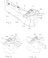
Fig. 1 is a top view of a distal radius plate according to the invention.Fig. 2 is a longitudinal section view along line 2-2 inFig. 1 .Fig. 3 is a bottom view of the plate ofFig. 1 .Fig. 4 is a perspective view of the plate ofFig. 1 shown on a portion of a distal radius bone.Fig. 5 is a top view and aFig. 6 is a longitudinal section view along line 6-6 inFig. 5 , both illustrating insertion of a K-wire into a hole in an extension tab of the distal radius plate prior to bending of the tab.Fig. 7 is a top view and aFig. 8 is a longitudinal section view along line 8-8 inFig. 7 , both illustrating use of a K-wire for bending of the extension tab of the distal radius plate with the K-wire inserted into the hole in the extension tab.Figs. 9 and 10 are perspective views illustrating the advancement of a suture needle and suture through the hole in an extension tab to secure soft tissue at the joint capsule.- Turning now to
Figs. 1 through 4 , abone plate 10 for stabilization of a fracture of adistal radius bone 100 is shown. Theplate 10 includes ashaft 12 for placement on thediaphysis 102 of thedistal radius bone 100, and ahead 14 at a transverse orientation relative to the shaft for placement on themetaphysis 104. The plate includes a bone contactinglower surface 16 and an oppositeupper surface 18. The head is in angled upward relative to the shaft when thelower surface 16 of the shaft is positioned substantially horizontal and face down in contact with the diaphysis of the radius bone. - The
shaft 12 andhead 14 each include holes for receiving fasteners to couple theplate 10 to thebone 100. Theshaft 12 preferably includes a combination of compression holes 20, 22 and non-compression fixed angle, threaded holes 24. The compression holes preferably comprise bothcircular holes 20 andelongate slots 22. Preferably, theholes US Serial No. 13/313,350 , (US 2013150901 Publication Number) filed December 7, 2011 . Holes of another design for suitable fasteners may also be used; however, it is preferable that any provided holes and arrangement thereof include both circular holes and slots, and that such circular holes include a combination of compression holes for compression fasteners and fixed angled holes such as can accommodate a fastener with a threaded head in a fixed orientation. The plate may also include one of more K-wire holes 26 to closely receive respective K-wires for temporary fixation of theshaft 12 of the plate relative to thebone 100. - The
holes 28 in the head of theplate 14 are threaded, fixed angle holes, with the threads of each hole defining a respective fixed axis for a fastener inserted therethrough. In a preferred embodiment, the threadedholes 28 are preferably of a same configuration and size as the threadedholes 24, and thus capable of receiving and fixing a common fastener therewith. Oneexemplar fastener 150 is shown in phantom inFig. 2 . Theholes 28 are preferably arranged in two rows; a relativelyproximal row 30 and a relativelydistal row 32, therows proximal row 30 of holes includes four threadedholes 28, and thedistal row 32 includes three threadedholes 28 preferably arranged in an offset from theproximal row 30 such that the shafts of fasteners inserted in theproximal row 30 can extend distally between the shafts of the fasteners inserted in thedistal row 32 in an interleaved manner. More preferably, when the plate is positioned on the bone at the intended location, thefasteners 150 extend into the bone in a spatial distribution about the articular surface 106 (Fig. 4 ) of the wrist socket to provide subchondral support. All the threaded fixed angle holes 28 within thehead 14 of the plate are provided to be located in the subchondral bone below the inflexion point of the watershed line (seen also inFig. 6 ) on the volar side of the distal radius. Preferred locations of the threadedholes 28 relative to the volar distal radius and preferred axial orientations of such threaded holes are described in detail inUS Pat. No. 7,294,130 . - K-wire holes are also preferably provided relative to the threaded holes in the head of the plate. Two K-
wire holes proximal row 30 of threaded holes. The K-wire holes plate 10 by the sidewalls of the respective K-wire hole. Such holes can be used for temporary fixation of the plate to the bone. Further, the K-wire, whether or not providing such temporary fixation, can be examined under fluoroscopy to analyze its trajectory relative to the bone anatomy and thereby provide information with respect to the apparent trajectory of fasteners through the adjacent threaded holes. In this manner, the K-wires inserted through the K-wire holes provided feedback as to the appropriate placement of the plate prior to drilling larger holes in the bone for the relatively larger fasteners. An additional K-wire hole 38 is preferably provided between two of the holes in thedistal row 32. In addition, other small holes, such as 38 can be provided to the head of the plate. Such other small holes may be additional K-wire holes of the types described for the purpose of guiding a K-wire or the plate relative to the K-wire, or may be of the same or different structure so as
to be otherwise adapted as anchor holes for suture to secure bone fragments and soft tissue relative to the plate. - Referring to
Figs. 1 and 3 , theradial side 40 of theplate 10 is tapered to adistal edge 54 and sized and shaped to seat completely below the `watershed'inflexion line 108 of the boney crest. In distinction, the ulnar (i.e., medial)side 42 of the distal edge of the plate is provided with two distally extendingtabs space 48. While thetabs side 42 of the distal edge, the tabs do not extend the lateral dimension of the head of the plate; the entire extension is preferably distal and displaced to the ulnar side. Thetabs distal end 54 of the plate such that thetabs ulnar facet 110 thereof (Figs. 4 and5 ). This allows thetabs tabs ulnar side tab 44 and anintermediate tab 46, with 'intermediate' defining a location between the ulnar and radial sides of the distal radius when the plate is positioned on the volar side of the distal radius (and not a relative location between other tabs). Theulnar side tab 44 is located distally in front of the medialmost (ulnar side) threaded hole 28a of thedistal row 32 of threadedholes 28, and theintermediate tab 46 is located distally in front of the central threaded hole 28b of thedistal row 32 of threaded holes 28 (Fig.1 ). Thetabs ulnar side tab 44 and toward the lateral side of theintermediate tab 46. This provides the upper surface of thetabs Fig. 2 , thelower surfaces 62 of the tabs are angled relative to the lower surface 60 at the remainder of the lower surface of thehead 14. That is, while the remainder of the lower surface 60 of thehead 14 is configured to seat in the concavity on the bone below the `watershed' inflexion line of the distal radius, thetabs volar rim 110. Thus, thelower surfaces 62 of thetabs - Referring to
Figs. 2 and 3 , in accord with the invention, thetabs volar rim 110 and provide close support to a fragment of the volar rim. Eachtab wire hole wire hole 58, the hole has an approximate diameter of 1.6 mm to provide the necessary clearance for passage of the K-wire. The axes of theholes tabs lower surface 16 at the tabs, as shown by angle β (Fig. 2 ) and also seen inFig. 3 . Thetabs lower recesses lower surface 16 of the plate, therecesses distal edge 54 of theradial side 40 of the plate are in alignment. Therecesses tabs head 14 without requiring that the width of the tabs be reduced. That is, it is preferable that the junctions between the tabs and the remainder of the head are not reduced in the width (in a medial-lateral direction) relative to the respective tabs. As a result of the reduced cross-sectional area moment of inertia at the junctions, when a force is applied to a tab, all plastic deformation will be located at the reduced cross-sectional area--leaving the tab and the K-wire hole without deformation-and thetabs distal edge 54. Therecesses tab Figs. 5-8 , with the K-wire 200 inserted into the K-wire hole 58 oftab 46, the K-wire 200 is able to apply a bending load to thetab 46 in situ to bend the tab about itslower recess 52, e.g., in the direction ofarrow 202, into a new orientation to best match the patient anatomy and provide support for the ulnar facet of thevolar rim 110. Therefore, the plate does not require a dedicated bender. Moreover, the K-wire 200 is an extremely unobtrusive tool for use during the surgical procedure, providing excellent visibility to the remainder of theplate 10 and surgical wound during the bending operation to allow the surgeon to visually confirm plate-to-anatomy conformation. Using the K-wire 200, thetabs Fig. 6 , it is preferable that, for purposes of tab bending, a K-wire 200 be insertedblunt side 204 down toward the bone to prevent the sharpenedtips 206 at the opposite end from catching the bone and inhibiting bending or inadvertently displacing loose bone fragments. - In addition, the K-
wire holes plate 10 and the remainder of thedistal radius 100 with a K-wire. In such use, one or more K-wires are preferably inserted via a drill, with the sharpenedside 206 of the K-wire inserted down into the bone. - Turning now to
Figs. 9 and 10 , thetabs wire hole peripheral edge 70 of the respective tab to accommodate passage of a 3/8 inchcircle suture needle 210 completely therethrough. For this purpose and other reasons, theholes edge 70 of therespective tabs hole 58 intab 46. This allows thetab 46 to receivesuture 212 to capture the smallest bone fragment and further repair the joint capsule at the fracture site. - The plate provides stability to volar distal radius fractures, particularly where support of the volar rim is desirable. The tabs extending from the ulnar side of the plate do not require any attachment to the plate at the time of the surgical procedure; they are integrated into the plate preventing the potential for otherwise loose components to drop into the surgical wound, reduce implantation time, and eliminate potential difficulties. Further, the tabs are easily bent to confirm to the underlying boney anatomy to best buttress the volar rim and/or place suture holes in a location suitable for soft tissue repair. Also, such tabs are designed to be non-irritating to surrounding soft tissue.
Claims (8)
- A bone plate (10) for a volar side of a distal radius bone (100), the bone having a diaphyseal portion (102) and a metaphyseal portion (104), an end of the metaphyseal portion having a concave articular surface and a rim (110) extending at least partially about the articular surface, the bone plate comprising:a bone contacting lower surface (16);an upper surface (18) opposite of the lower surface (16);a shaft (12) configured to be secured to the diaphyseal portion of the bone;a head (14) extending from the shaft at a transverse orientation relative to the shaft, the head angled upwards relative to the shaft and having a distal edge (54), a first ulnar side (42) and a second radial side (40) with respect to the position of the bone plate in use on the volar side of the bone (100), the head comprising one or more fastener holes (28) for receiving one or more fasteners (150) to secure the head to the metaphyseal portion of the bone, the one or more fastener holes (28) including a proximal row of holes (30) and a distal row of holes (32), the fastener holes (28) in the distal row (32) are offset from the fastener holes in the proximal row (30), and the proximal row (30) of holes includes four threaded holes (28) and the distal row (32) of holes includes at least two threaded holes (28);a first tab (44) extending from the distal edge (54) of the head (14) on the first ulnar side (42); anda second tab (46) extending from the distal edge (54) of the head (14) between the first tab (44) and the second side (40), the first and second tabs (44,46) separated from each other by a space (48), each of the first and second tabs being independently re-orientable about an axis in alignment with the distal edge (54),wherein the head (14) is configured to seat proximally below the rim (110) of the metaphyseal portion, and the first and second tabs (44,46) are configured to extend over the rim (110) of the metaphyseal portion (104).
- The bone plate of claim 1, wherein the lower surface (16) comprises a recess (50,52) formed at a junction between each of the first and second tabs (44,46) and the head (14) at the distal edge (54), and wherein the recess (50,52) reduces a cross-sectional area moment of inertia at the junction.
- The bone plate of claim 2, wherein the recess (50,52) extends along an entire junction between the respective tab (44,46) and the head (14).
- The bone plate of any one of claims 2 or 3, wherein a width of the junction of each of the first and second tabs (44,46) is approximately equal to a width of a body of the respective tab (44,46).
- The bone plate of any one of claims 1-4, wherein the shaft (12) comprises one or more fastener holes (24) for receiving one or more fasteners to secure the shaft (12) to the diaphyseal portion (102) of the bone (100).
- The bone plate of any one of claims 1-5, wherein the shaft (12) comprises one or more K-wire holes (26) for receiving a K-wire.
- The bone plate of any one of claims 1-6, wherein the head (14) comprises one or more K-wire holes (34,36,38) for receiving a K-wire.
- The bone plate of any one of claims 1-7, wherein each of the first and second tabs (44,46) comprise a non-threaded hole (56,58) configured to receive a K-wire for applying a bending load to the first or second tab (44,46) in situ to bend the tab into a new orientation.
Applications Claiming Priority (3)
| Application Number | Priority Date | Filing Date | Title |
|---|---|---|---|
| US13/364,513US8790378B2 (en) | 2012-02-02 | 2012-02-02 | Distal radius fracture fixation plate with integrated and adjustable volar ulnar facet support |
| EP12816809.3AEP2809251B1 (en) | 2012-02-02 | 2012-12-13 | Distal radius fracture fixation plate with integrated and adjustable volar ulnar facet support |
| PCT/US2012/069342WO2013115911A1 (en) | 2012-02-02 | 2012-12-13 | Distal radius fracture fixation plate with integrated and adjustable volar ulnar facet support |
Related Parent Applications (1)
| Application Number | Title | Priority Date | Filing Date |
|---|---|---|---|
| EP12816809.3ADivisionEP2809251B1 (en) | 2012-02-02 | 2012-12-13 | Distal radius fracture fixation plate with integrated and adjustable volar ulnar facet support |
Publications (3)
| Publication Number | Publication Date |
|---|---|
| EP3318208A2 EP3318208A2 (en) | 2018-05-09 |
| EP3318208A3 EP3318208A3 (en) | 2018-08-22 |
| EP3318208B1true EP3318208B1 (en) | 2023-10-04 |
Family
ID=47599154
Family Applications (2)
| Application Number | Title | Priority Date | Filing Date |
|---|---|---|---|
| EP12816809.3AActiveEP2809251B1 (en) | 2012-02-02 | 2012-12-13 | Distal radius fracture fixation plate with integrated and adjustable volar ulnar facet support |
| EP17153977.8AActiveEP3318208B1 (en) | 2012-02-02 | 2012-12-13 | Distal radius fracture fixation plate with integrated and adjustable volar ulnar facet support |
Family Applications Before (1)
| Application Number | Title | Priority Date | Filing Date |
|---|---|---|---|
| EP12816809.3AActiveEP2809251B1 (en) | 2012-02-02 | 2012-12-13 | Distal radius fracture fixation plate with integrated and adjustable volar ulnar facet support |
Country Status (4)
| Country | Link |
|---|---|
| US (3) | US8790378B2 (en) |
| EP (2) | EP2809251B1 (en) |
| ES (1) | ES2616137T3 (en) |
| WO (1) | WO2013115911A1 (en) |
Families Citing this family (25)
| Publication number | Priority date | Publication date | Assignee | Title |
|---|---|---|---|---|
| US10390867B2 (en) | 2009-09-18 | 2019-08-27 | Biomet C.V. | Bone plate system and method |
| US9907582B1 (en) | 2011-04-25 | 2018-03-06 | Nuvasive, Inc. | Minimally invasive spinal fixation system and related methods |
| WO2013036362A1 (en) | 2011-09-06 | 2013-03-14 | Synthes Usa, Llc | Pancarpal arthrodesis bone plate |
| WO2013036582A1 (en)* | 2011-09-06 | 2013-03-14 | Skeletal Dynamics, L.L.C. | Fracture fixation plate, system and methods of use |
| US9220549B2 (en)* | 2011-09-27 | 2015-12-29 | Steven Glickel | Distal radius volar locking plate with extension for ulnar volar fragment |
| US8790378B2 (en) | 2012-02-02 | 2014-07-29 | Biomet C.V. | Distal radius fracture fixation plate with integrated and adjustable volar ulnar facet support |
| US20140277178A1 (en)* | 2013-03-13 | 2014-09-18 | Wright Medical Technology, Inc. | Posterior Ankle Fusion Plate |
| EP3065656B1 (en) | 2013-11-05 | 2020-12-23 | Arthrex, Inc. | Tplo plate with suture holes for rotational stability |
| US9895180B2 (en)* | 2014-05-15 | 2018-02-20 | Osteomed Llc | Ankle tibia plates |
| US9743965B2 (en)* | 2014-06-20 | 2017-08-29 | DePuy Synthes Products, Inc. | Medial column fusion plates |
| AU2015308881B2 (en)* | 2014-08-28 | 2019-03-14 | Zimmer Gmbh | Bone plate system and method |
| US9730686B2 (en)* | 2014-09-03 | 2017-08-15 | Biomet C.V. | System and method of soft tissue anchoring to metaphyseal bone plate |
| CN104224299A (en)* | 2014-09-23 | 2014-12-24 | 江苏百易得医疗科技有限公司 | Bone-bonding adjustable-type bone-connecting plate |
| USD779065S1 (en) | 2014-10-08 | 2017-02-14 | Nuvasive, Inc. | Anterior cervical bone plate |
| CN104814785B (en)* | 2015-05-13 | 2017-06-20 | 刘观燚 | Coronoid process of ulna mixed lateral column steel plate |
| US10939943B2 (en) | 2016-01-04 | 2021-03-09 | OsteoCertus, LLC | Orthopedic bone plate system |
| US10478237B2 (en) | 2016-01-04 | 2019-11-19 | OsteoCertus, LLC | Orthopedic bone plate system |
| US10258402B2 (en) | 2016-01-04 | 2019-04-16 | OsteoCertus, LLC | Orthopedic bone plate system |
| US10940023B2 (en) | 2016-12-15 | 2021-03-09 | Stryker European Holdings I, Llc | Bone plate trial |
| US10905477B2 (en)* | 2017-03-13 | 2021-02-02 | Globus Medical, Inc. | Bone stabilization systems |
| JP2021506559A (en) | 2017-12-20 | 2021-02-22 | グレンハースト ラブス エルエルシー | Multi-faceted fixation plate for fracture repair |
| EP3530224A1 (en)* | 2018-02-23 | 2019-08-28 | Medartis Holding AG | Wrist arthrodesis plate |
| US11944361B2 (en) | 2019-08-09 | 2024-04-02 | DePuy Synthes Products, Inc. | Bone plate with structures for attachment of sutures |
| US12402923B2 (en) | 2022-10-04 | 2025-09-02 | DePuy Synthes Products, Inc. | Offset hole for TPLO compression |
| CN116650088B (en)* | 2023-07-26 | 2024-02-27 | 北京纳通医学研究院有限公司 | Distal radius plate and distal radius plate system |
Citations (1)
| Publication number | Priority date | Publication date | Assignee | Title |
|---|---|---|---|---|
| US7250053B2 (en)* | 2003-03-27 | 2007-07-31 | Depuy Products, Inc. | Low profile distal radius fracture fixation plate |
Family Cites Families (61)
| Publication number | Priority date | Publication date | Assignee | Title |
|---|---|---|---|---|
| FR742618A (en) | 1933-03-10 | |||
| US3741205A (en) | 1971-06-14 | 1973-06-26 | K Markolf | Bone fixation plate |
| US3842825A (en) | 1973-11-12 | 1974-10-22 | R Wagner | Hip fixation device |
| CH613858A5 (en) | 1977-04-22 | 1979-10-31 | Straumann Inst Ag | |
| CH645264A5 (en) | 1980-05-28 | 1984-09-28 | Straumann Inst Ag | FITTING WITH A PLATE AND SCREWS THAT FIX IT TO A BONE. |
| US4573458A (en) | 1982-08-17 | 1986-03-04 | Zimmer, Inc. | Bone fixation plate |
| GB8515870D0 (en) | 1985-06-22 | 1985-07-24 | Showell A W Sugicraft Ltd | Bone fixation plates |
| US4776330A (en) | 1986-06-23 | 1988-10-11 | Pfizer Hospital Products Group, Inc. | Modular femoral fixation system |
| DE8628766U1 (en) | 1986-10-25 | 1986-12-11 | Mecron Medizinische Produkte Gmbh, 1000 Berlin | Bone plate |
| MX170527B (en) | 1987-11-03 | 1993-08-30 | Synthes Ag | IMPLEMENTATION FOR OSTEOSYNTHESIS |
| US4955886A (en) | 1988-04-01 | 1990-09-11 | The Trustees Of Columbia University In The City Of New York | Dual-taper, asymmetric hole placement in reconstruction and fracture plates |
| US4973332A (en) | 1988-09-12 | 1990-11-27 | Hospital For Joint Diseases | Attachment for femur sliding screw plate |
| SE8903403D0 (en) | 1989-10-16 | 1989-10-16 | Sven Olerud | DEVICE FOR FIXING INSTRUMENTS FOR BACKGROUND OPERATIONS |
| JPH066810Y2 (en) | 1989-11-29 | 1994-02-23 | 旭光学工業株式会社 | Vertebral body fixation plate |
| DE69320593T2 (en) | 1992-11-25 | 1999-03-04 | Codman & Shurtleff, Inc., Randolph, Mass. | Bone plate system |
| DE59509247D1 (en) | 1995-09-06 | 2001-06-13 | Synthes Ag | BONE PLATE |
| US5647712A (en) | 1996-05-09 | 1997-07-15 | Fleetguard, Inc. | One directional socket-driven component |
| US6123709A (en) | 1997-07-25 | 2000-09-26 | Jones; Andrew R. | Bone buttress plate and method of using same |
| US5954722A (en) | 1997-07-29 | 1999-09-21 | Depuy Acromed, Inc. | Polyaxial locking plate |
| US6004353A (en) | 1997-07-30 | 1999-12-21 | Medidea, Llc | Modular acetabular reconstruction plate |
| US6454769B2 (en) | 1997-08-04 | 2002-09-24 | Spinal Concepts, Inc. | System and method for stabilizing the human spine with a bone plate |
| BR9815996A (en) | 1998-08-25 | 2001-05-02 | Medartis Ag | Osteosynthetic fixation device |
| CN1172634C (en) | 1999-09-13 | 2004-10-27 | 库尔斯恩蒂斯股份公司 | Bone plating system |
| DE19951760B4 (en) | 1999-10-27 | 2005-06-09 | Sepitec Foundation | Implant for osteosynthesis |
| US6866665B2 (en) | 2003-03-27 | 2005-03-15 | Hand Innovations, Llc | Bone fracture fixation system with subchondral and articular surface support |
| US6712820B2 (en)* | 2000-02-01 | 2004-03-30 | Hand Innovations, Inc. | Fixation plate system for dorsal wrist fracture fixation |
| US6358250B1 (en) | 2000-02-01 | 2002-03-19 | Hand Innovations, Inc. | Volar fixation system |
| US6565570B2 (en) | 2001-03-14 | 2003-05-20 | Electro-Biology, Inc. | Bone plate and retractor assembly |
| US20050234458A1 (en) | 2004-04-19 | 2005-10-20 | Huebner Randall J | Expanded stabilization of bones |
| FR2827500B1 (en)* | 2001-07-17 | 2004-04-02 | Tornier Sa | PLATE OF OSTEOSYNTHESIS OF THE UPPER END OF THE HUMERUS |
| US6652530B2 (en) | 2001-09-19 | 2003-11-25 | The University Of Hong Kong | Fixation device |
| AU2003294414B2 (en) | 2002-11-19 | 2009-03-12 | Acumed Llc | Deformable bone plates |
| US7294130B2 (en) | 2003-03-27 | 2007-11-13 | Depuy Products, Inc. | Distal radius fracture fixation plate having K-wire hole structured to fix a K-wire in one dimension relative to the plate |
| US7951176B2 (en) | 2003-05-30 | 2011-05-31 | Synthes Usa, Llc | Bone plate |
| US20050085818A1 (en) | 2003-10-17 | 2005-04-21 | Huebner Randall J. | Systems for distal radius fixation |
| US7604657B2 (en) | 2005-09-19 | 2009-10-20 | Depuy Products, Inc. | Bone fixation plate with complex suture anchor locations |
| DE202005014850U1 (en) | 2005-09-20 | 2007-02-01 | Karl Leibinger Medizintechnik Gmbh & Co. Kg | System for fixation of bone segments or fragments |
| US8029551B2 (en)* | 2006-01-10 | 2011-10-04 | Running Donald E | Fracture fixation plate with cover sheath |
| US8574235B2 (en) | 2006-02-03 | 2013-11-05 | Biomet Sports Medicine, Llc | Method for trochanteric reattachment |
| US8562647B2 (en) | 2006-09-29 | 2013-10-22 | Biomet Sports Medicine, Llc | Method and apparatus for securing soft tissue to bone |
| US8021402B2 (en) | 2006-03-07 | 2011-09-20 | Orthohelix Surgical Designs, Inc. | Distal radius plate |
| US7935126B2 (en)* | 2006-03-20 | 2011-05-03 | Depuy Products, Inc. | Bone plate shaping system |
| US20070270849A1 (en) | 2006-04-21 | 2007-11-22 | Orbay Jorge L | Fixation Plate With Multifunctional Holes |
| US8398687B2 (en) | 2006-12-06 | 2013-03-19 | Amei Technologies, Inc. | Volar plate fixation device |
| US7818542B2 (en) | 2007-07-10 | 2010-10-19 | Globalfoundries Inc. | Method and apparatus for length decoding variable length instructions |
| US20090018587A1 (en) | 2007-07-11 | 2009-01-15 | Apex Biomedical Company, Llc | Fracture plate and method for fixation of same to a bone shaft |
| EP2397094B1 (en)* | 2007-11-02 | 2013-06-26 | Biomet C.V. | Elbow fracture fixation system |
| US8317842B2 (en) | 2007-11-30 | 2012-11-27 | Biomet C.V. | Distal tibia plating system |
| AU2008354730A1 (en) | 2008-04-17 | 2009-10-22 | Toby Orthopaedics, Inc. | Soft tissue attachment system and clip |
| US8652179B2 (en) | 2008-05-02 | 2014-02-18 | The Cleveland Clinic Foundation | Bone plate extender and extension system for bone restoration and methods of use thereof |
| US20100057086A1 (en) | 2008-08-29 | 2010-03-04 | Zimmer, Inc. | Anodized locking plate components |
| US20100262185A1 (en) | 2009-04-10 | 2010-10-14 | Suspension Orthopaedic Solutions, Llc | Method and apparatus for aperture fixation by securing flexible material with a knotless fixation device |
| GB0914673D0 (en) | 2009-08-24 | 2009-09-30 | Kumar Deepak | Fracture buttress fixation system |
| JP5756118B2 (en) | 2009-11-17 | 2015-07-29 | シンセス ゲゼルシャフト ミット ベシュレンクテル ハフツングSynthes Gmbh | Fixed support pin with variable angle |
| EP2729200B1 (en) | 2011-07-06 | 2016-10-19 | F.Hoffmann-La Roche Ag | Automatic injection device comprising two occlusion sensors |
| US9220549B2 (en)* | 2011-09-27 | 2015-12-29 | Steven Glickel | Distal radius volar locking plate with extension for ulnar volar fragment |
| US8632574B2 (en) | 2011-12-07 | 2014-01-21 | Biomet C.V. | Reduced component bone plating system |
| US9259217B2 (en) | 2012-01-03 | 2016-02-16 | Biomet Manufacturing, Llc | Suture Button |
| US8790378B2 (en) | 2012-02-02 | 2014-07-29 | Biomet C.V. | Distal radius fracture fixation plate with integrated and adjustable volar ulnar facet support |
| EP2730244B1 (en) | 2012-11-07 | 2017-04-26 | Arthrex, Inc. | Bone plate with suture holes for soft tissue reattachment on the diaphyseal region of the plate |
| US9730686B2 (en) | 2014-09-03 | 2017-08-15 | Biomet C.V. | System and method of soft tissue anchoring to metaphyseal bone plate |
- 2012
- 2012-02-02USUS13/364,513patent/US8790378B2/enactiveActive
- 2012-12-13WOPCT/US2012/069342patent/WO2013115911A1/enactiveApplication Filing
- 2012-12-13EPEP12816809.3Apatent/EP2809251B1/enactiveActive
- 2012-12-13ESES12816809.3Tpatent/ES2616137T3/enactiveActive
- 2012-12-13EPEP17153977.8Apatent/EP3318208B1/enactiveActive
- 2014
- 2014-05-30USUS14/291,113patent/US9510881B2/enactiveActive
- 2016
- 2016-11-21USUS15/357,521patent/US10278750B2/enactiveActive
Patent Citations (1)
| Publication number | Priority date | Publication date | Assignee | Title |
|---|---|---|---|---|
| US7250053B2 (en)* | 2003-03-27 | 2007-07-31 | Depuy Products, Inc. | Low profile distal radius fracture fixation plate |
Also Published As
| Publication number | Publication date |
|---|---|
| US20130204307A1 (en) | 2013-08-08 |
| EP2809251B1 (en) | 2017-02-01 |
| WO2013115911A1 (en) | 2013-08-08 |
| ES2616137T3 (en) | 2017-06-09 |
| US20170065316A1 (en) | 2017-03-09 |
| US9510881B2 (en) | 2016-12-06 |
| US8790378B2 (en) | 2014-07-29 |
| US20140330321A1 (en) | 2014-11-06 |
| EP3318208A2 (en) | 2018-05-09 |
| EP3318208A3 (en) | 2018-08-22 |
| EP2809251A1 (en) | 2014-12-10 |
| US10278750B2 (en) | 2019-05-07 |
Similar Documents
| Publication | Publication Date | Title |
|---|---|---|
| US10278750B2 (en) | Method of stabilizing a fracture at a metaphysis defining a concave articular surface | |
| US10130401B2 (en) | Growth control device | |
| US7686808B2 (en) | Fracture fixation device and implantation jig therefor | |
| US8911443B2 (en) | Plate holder for manipulating bone plate | |
| EP2389884B1 (en) | Implant for bone fixation | |
| US20180250044A1 (en) | Systems and methods for using polyaxial plates | |
| US20120010667A1 (en) | Fracture-specific distal radius plates | |
| US20060161156A1 (en) | Fracture fixation device | |
| US20060149257A1 (en) | Fracture fixation device | |
| JP2014046200A (en) | Contoured bone plate for fracture fixation having hook members and holder/impactor for same | |
| AU2015313920B2 (en) | System and method of soft tissue anchoring to metaphyseal bone plate | |
| US8668693B2 (en) | Fixation device for proximal elbow fractures and method of using same | |
| US20120016366A1 (en) | Proximal Radius Locking Plate | |
| IL193043A (en) | Fracture fixation device and implantation jig therefor |
Legal Events
| Date | Code | Title | Description |
|---|---|---|---|
| PUAI | Public reference made under article 153(3) epc to a published international application that has entered the european phase | Free format text:ORIGINAL CODE: 0009012 | |
| STAA | Information on the status of an ep patent application or granted ep patent | Free format text:STATUS: THE APPLICATION HAS BEEN PUBLISHED | |
| AC | Divisional application: reference to earlier application | Ref document number:2809251 Country of ref document:EP Kind code of ref document:P | |
| AK | Designated contracting states | Kind code of ref document:A2 Designated state(s):AL AT BE BG CH CY CZ DE DK EE ES FI FR GB GR HR HU IE IS IT LI LT LU LV MC MK MT NL NO PL PT RO RS SE SI SK SM TR | |
| PUAL | Search report despatched | Free format text:ORIGINAL CODE: 0009013 | |
| AK | Designated contracting states | Kind code of ref document:A3 Designated state(s):AL AT BE BG CH CY CZ DE DK EE ES FI FR GB GR HR HU IE IS IT LI LT LU LV MC MK MT NL NO PL PT RO RS SE SI SK SM TR | |
| RIC1 | Information provided on ipc code assigned before grant | Ipc:A61B 17/80 20060101AFI20180716BHEP | |
| STAA | Information on the status of an ep patent application or granted ep patent | Free format text:STATUS: REQUEST FOR EXAMINATION WAS MADE | |
| 17P | Request for examination filed | Effective date:20190222 | |
| RBV | Designated contracting states (corrected) | Designated state(s):AL AT BE BG CH CY CZ DE DK EE ES FI FR GB GR HR HU IE IS IT LI LT LU LV MC MK MT NL NO PL PT RO RS SE SI SK SM TR | |
| STAA | Information on the status of an ep patent application or granted ep patent | Free format text:STATUS: EXAMINATION IS IN PROGRESS | |
| 17Q | First examination report despatched | Effective date:20220208 | |
| GRAP | Despatch of communication of intention to grant a patent | Free format text:ORIGINAL CODE: EPIDOSNIGR1 | |
| STAA | Information on the status of an ep patent application or granted ep patent | Free format text:STATUS: GRANT OF PATENT IS INTENDED | |
| INTG | Intention to grant announced | Effective date:20230414 | |
| GRAS | Grant fee paid | Free format text:ORIGINAL CODE: EPIDOSNIGR3 | |
| GRAA | (expected) grant | Free format text:ORIGINAL CODE: 0009210 | |
| STAA | Information on the status of an ep patent application or granted ep patent | Free format text:STATUS: THE PATENT HAS BEEN GRANTED | |
| AC | Divisional application: reference to earlier application | Ref document number:2809251 Country of ref document:EP Kind code of ref document:P | |
| AK | Designated contracting states | Kind code of ref document:B1 Designated state(s):AL AT BE BG CH CY CZ DE DK EE ES FI FR GB GR HR HU IE IS IT LI LT LU LV MC MK MT NL NO PL PT RO RS SE SI SK SM TR | |
| REG | Reference to a national code | Ref country code:GB Ref legal event code:FG4D | |
| REG | Reference to a national code | Ref country code:CH Ref legal event code:EP | |
| REG | Reference to a national code | Ref country code:DE Ref legal event code:R096 Ref document number:602012080160 Country of ref document:DE | |
| REG | Reference to a national code | Ref country code:IE Ref legal event code:FG4D | |
| REG | Reference to a national code | Ref country code:LT Ref legal event code:MG9D | |
| REG | Reference to a national code | Ref country code:NL Ref legal event code:MP Effective date:20231004 | |
| REG | Reference to a national code | Ref country code:AT Ref legal event code:MK05 Ref document number:1616908 Country of ref document:AT Kind code of ref document:T Effective date:20231004 | |
| PG25 | Lapsed in a contracting state [announced via postgrant information from national office to epo] | Ref country code:NL Free format text:LAPSE BECAUSE OF FAILURE TO SUBMIT A TRANSLATION OF THE DESCRIPTION OR TO PAY THE FEE WITHIN THE PRESCRIBED TIME-LIMIT Effective date:20231004 | |
| PG25 | Lapsed in a contracting state [announced via postgrant information from national office to epo] | Ref country code:GR Free format text:LAPSE BECAUSE OF FAILURE TO SUBMIT A TRANSLATION OF THE DESCRIPTION OR TO PAY THE FEE WITHIN THE PRESCRIBED TIME-LIMIT Effective date:20240105 | |
| PG25 | Lapsed in a contracting state [announced via postgrant information from national office to epo] | Ref country code:IS Free format text:LAPSE BECAUSE OF FAILURE TO SUBMIT A TRANSLATION OF THE DESCRIPTION OR TO PAY THE FEE WITHIN THE PRESCRIBED TIME-LIMIT Effective date:20240204 | |
| PG25 | Lapsed in a contracting state [announced via postgrant information from national office to epo] | Ref country code:LT Free format text:LAPSE BECAUSE OF FAILURE TO SUBMIT A TRANSLATION OF THE DESCRIPTION OR TO PAY THE FEE WITHIN THE PRESCRIBED TIME-LIMIT Effective date:20231004 | |
| PG25 | Lapsed in a contracting state [announced via postgrant information from national office to epo] | Ref country code:AT Free format text:LAPSE BECAUSE OF FAILURE TO SUBMIT A TRANSLATION OF THE DESCRIPTION OR TO PAY THE FEE WITHIN THE PRESCRIBED TIME-LIMIT Effective date:20231004 | |
| PG25 | Lapsed in a contracting state [announced via postgrant information from national office to epo] | Ref country code:ES Free format text:LAPSE BECAUSE OF FAILURE TO SUBMIT A TRANSLATION OF THE DESCRIPTION OR TO PAY THE FEE WITHIN THE PRESCRIBED TIME-LIMIT Effective date:20231004 | |
| PG25 | Lapsed in a contracting state [announced via postgrant information from national office to epo] | Ref country code:LT Free format text:LAPSE BECAUSE OF FAILURE TO SUBMIT A TRANSLATION OF THE DESCRIPTION OR TO PAY THE FEE WITHIN THE PRESCRIBED TIME-LIMIT Effective date:20231004 Ref country code:IS Free format text:LAPSE BECAUSE OF FAILURE TO SUBMIT A TRANSLATION OF THE DESCRIPTION OR TO PAY THE FEE WITHIN THE PRESCRIBED TIME-LIMIT Effective date:20240204 Ref country code:GR Free format text:LAPSE BECAUSE OF FAILURE TO SUBMIT A TRANSLATION OF THE DESCRIPTION OR TO PAY THE FEE WITHIN THE PRESCRIBED TIME-LIMIT Effective date:20240105 Ref country code:ES Free format text:LAPSE BECAUSE OF FAILURE TO SUBMIT A TRANSLATION OF THE DESCRIPTION OR TO PAY THE FEE WITHIN THE PRESCRIBED TIME-LIMIT Effective date:20231004 Ref country code:BG Free format text:LAPSE BECAUSE OF FAILURE TO SUBMIT A TRANSLATION OF THE DESCRIPTION OR TO PAY THE FEE WITHIN THE PRESCRIBED TIME-LIMIT Effective date:20240104 Ref country code:AT Free format text:LAPSE BECAUSE OF FAILURE TO SUBMIT A TRANSLATION OF THE DESCRIPTION OR TO PAY THE FEE WITHIN THE PRESCRIBED TIME-LIMIT Effective date:20231004 Ref country code:PT Free format text:LAPSE BECAUSE OF FAILURE TO SUBMIT A TRANSLATION OF THE DESCRIPTION OR TO PAY THE FEE WITHIN THE PRESCRIBED TIME-LIMIT Effective date:20240205 | |
| P01 | Opt-out of the competence of the unified patent court (upc) registered | Effective date:20240326 | |
| PG25 | Lapsed in a contracting state [announced via postgrant information from national office to epo] | Ref country code:SE Free format text:LAPSE BECAUSE OF FAILURE TO SUBMIT A TRANSLATION OF THE DESCRIPTION OR TO PAY THE FEE WITHIN THE PRESCRIBED TIME-LIMIT Effective date:20231004 Ref country code:RS Free format text:LAPSE BECAUSE OF FAILURE TO SUBMIT A TRANSLATION OF THE DESCRIPTION OR TO PAY THE FEE WITHIN THE PRESCRIBED TIME-LIMIT Effective date:20231004 Ref country code:PL Free format text:LAPSE BECAUSE OF FAILURE TO SUBMIT A TRANSLATION OF THE DESCRIPTION OR TO PAY THE FEE WITHIN THE PRESCRIBED TIME-LIMIT Effective date:20231004 Ref country code:NO Free format text:LAPSE BECAUSE OF FAILURE TO SUBMIT A TRANSLATION OF THE DESCRIPTION OR TO PAY THE FEE WITHIN THE PRESCRIBED TIME-LIMIT Effective date:20240104 Ref country code:LV Free format text:LAPSE BECAUSE OF FAILURE TO SUBMIT A TRANSLATION OF THE DESCRIPTION OR TO PAY THE FEE WITHIN THE PRESCRIBED TIME-LIMIT Effective date:20231004 Ref country code:HR Free format text:LAPSE BECAUSE OF FAILURE TO SUBMIT A TRANSLATION OF THE DESCRIPTION OR TO PAY THE FEE WITHIN THE PRESCRIBED TIME-LIMIT Effective date:20231004 | |
| REG | Reference to a national code | Ref country code:DE Ref legal event code:R097 Ref document number:602012080160 Country of ref document:DE | |
| PG25 | Lapsed in a contracting state [announced via postgrant information from national office to epo] | Ref country code:DK Free format text:LAPSE BECAUSE OF FAILURE TO SUBMIT A TRANSLATION OF THE DESCRIPTION OR TO PAY THE FEE WITHIN THE PRESCRIBED TIME-LIMIT Effective date:20231004 | |
| PG25 | Lapsed in a contracting state [announced via postgrant information from national office to epo] | Ref country code:CZ Free format text:LAPSE BECAUSE OF FAILURE TO SUBMIT A TRANSLATION OF THE DESCRIPTION OR TO PAY THE FEE WITHIN THE PRESCRIBED TIME-LIMIT Effective date:20231004 | |
| PG25 | Lapsed in a contracting state [announced via postgrant information from national office to epo] | Ref country code:SK Free format text:LAPSE BECAUSE OF FAILURE TO SUBMIT A TRANSLATION OF THE DESCRIPTION OR TO PAY THE FEE WITHIN THE PRESCRIBED TIME-LIMIT Effective date:20231004 | |
| PG25 | Lapsed in a contracting state [announced via postgrant information from national office to epo] | Ref country code:SM Free format text:LAPSE BECAUSE OF FAILURE TO SUBMIT A TRANSLATION OF THE DESCRIPTION OR TO PAY THE FEE WITHIN THE PRESCRIBED TIME-LIMIT Effective date:20231004 Ref country code:SK Free format text:LAPSE BECAUSE OF FAILURE TO SUBMIT A TRANSLATION OF THE DESCRIPTION OR TO PAY THE FEE WITHIN THE PRESCRIBED TIME-LIMIT Effective date:20231004 Ref country code:RO Free format text:LAPSE BECAUSE OF FAILURE TO SUBMIT A TRANSLATION OF THE DESCRIPTION OR TO PAY THE FEE WITHIN THE PRESCRIBED TIME-LIMIT Effective date:20231004 Ref country code:IT Free format text:LAPSE BECAUSE OF FAILURE TO SUBMIT A TRANSLATION OF THE DESCRIPTION OR TO PAY THE FEE WITHIN THE PRESCRIBED TIME-LIMIT Effective date:20231004 Ref country code:EE Free format text:LAPSE BECAUSE OF FAILURE TO SUBMIT A TRANSLATION OF THE DESCRIPTION OR TO PAY THE FEE WITHIN THE PRESCRIBED TIME-LIMIT Effective date:20231004 Ref country code:DK Free format text:LAPSE BECAUSE OF FAILURE TO SUBMIT A TRANSLATION OF THE DESCRIPTION OR TO PAY THE FEE WITHIN THE PRESCRIBED TIME-LIMIT Effective date:20231004 Ref country code:CZ Free format text:LAPSE BECAUSE OF FAILURE TO SUBMIT A TRANSLATION OF THE DESCRIPTION OR TO PAY THE FEE WITHIN THE PRESCRIBED TIME-LIMIT Effective date:20231004 | |
| PLBE | No opposition filed within time limit | Free format text:ORIGINAL CODE: 0009261 | |
| STAA | Information on the status of an ep patent application or granted ep patent | Free format text:STATUS: NO OPPOSITION FILED WITHIN TIME LIMIT | |
| PG25 | Lapsed in a contracting state [announced via postgrant information from national office to epo] | Ref country code:LU Free format text:LAPSE BECAUSE OF NON-PAYMENT OF DUE FEES Effective date:20231213 | |
| REG | Reference to a national code | Ref country code:DE Ref legal event code:R081 Ref document number:602012080160 Country of ref document:DE Owner name:ZIMMER GMBH, CH Free format text:FORMER OWNER: BIOMET C.V., GIBRALTAR, GI | |
| PG25 | Lapsed in a contracting state [announced via postgrant information from national office to epo] | Ref country code:MC Free format text:LAPSE BECAUSE OF FAILURE TO SUBMIT A TRANSLATION OF THE DESCRIPTION OR TO PAY THE FEE WITHIN THE PRESCRIBED TIME-LIMIT Effective date:20231004 | |
| REG | Reference to a national code | Ref country code:BE Ref legal event code:MM Effective date:20231231 | |
| PG25 | Lapsed in a contracting state [announced via postgrant information from national office to epo] | Ref country code:MC Free format text:LAPSE BECAUSE OF FAILURE TO SUBMIT A TRANSLATION OF THE DESCRIPTION OR TO PAY THE FEE WITHIN THE PRESCRIBED TIME-LIMIT Effective date:20231004 Ref country code:LU Free format text:LAPSE BECAUSE OF NON-PAYMENT OF DUE FEES Effective date:20231213 | |
| 26N | No opposition filed | Effective date:20240705 | |
| REG | Reference to a national code | Ref country code:GB Ref legal event code:732E Free format text:REGISTERED BETWEEN 20240815 AND 20240821 | |
| REG | Reference to a national code | Ref country code:IE Ref legal event code:MM4A | |
| PG25 | Lapsed in a contracting state [announced via postgrant information from national office to epo] | Ref country code:IE Free format text:LAPSE BECAUSE OF NON-PAYMENT OF DUE FEES Effective date:20231213 | |
| PG25 | Lapsed in a contracting state [announced via postgrant information from national office to epo] | Ref country code:BE Free format text:LAPSE BECAUSE OF NON-PAYMENT OF DUE FEES Effective date:20231231 | |
| PG25 | Lapsed in a contracting state [announced via postgrant information from national office to epo] | Ref country code:SI Free format text:LAPSE BECAUSE OF FAILURE TO SUBMIT A TRANSLATION OF THE DESCRIPTION OR TO PAY THE FEE WITHIN THE PRESCRIBED TIME-LIMIT Effective date:20231004 | |
| PG25 | Lapsed in a contracting state [announced via postgrant information from national office to epo] | Ref country code:SI Free format text:LAPSE BECAUSE OF FAILURE TO SUBMIT A TRANSLATION OF THE DESCRIPTION OR TO PAY THE FEE WITHIN THE PRESCRIBED TIME-LIMIT Effective date:20231004 Ref country code:IE Free format text:LAPSE BECAUSE OF NON-PAYMENT OF DUE FEES Effective date:20231213 Ref country code:BE Free format text:LAPSE BECAUSE OF NON-PAYMENT OF DUE FEES Effective date:20231231 | |
| PGFP | Annual fee paid to national office [announced via postgrant information from national office to epo] | Ref country code:DE Payment date:20241111 Year of fee payment:13 | |
| PGFP | Annual fee paid to national office [announced via postgrant information from national office to epo] | Ref country code:GB Payment date:20241115 Year of fee payment:13 | |
| PGFP | Annual fee paid to national office [announced via postgrant information from national office to epo] | Ref country code:FR Payment date:20241115 Year of fee payment:13 | |
| PGFP | Annual fee paid to national office [announced via postgrant information from national office to epo] | Ref country code:CH Payment date:20250101 Year of fee payment:13 | |
| PG25 | Lapsed in a contracting state [announced via postgrant information from national office to epo] | Ref country code:FI Free format text:LAPSE BECAUSE OF FAILURE TO SUBMIT A TRANSLATION OF THE DESCRIPTION OR TO PAY THE FEE WITHIN THE PRESCRIBED TIME-LIMIT Effective date:20231004 | |
| PG25 | Lapsed in a contracting state [announced via postgrant information from national office to epo] | Ref country code:CY Free format text:LAPSE BECAUSE OF FAILURE TO SUBMIT A TRANSLATION OF THE DESCRIPTION OR TO PAY THE FEE WITHIN THE PRESCRIBED TIME-LIMIT; INVALID AB INITIO Effective date:20121213 | |
| PG25 | Lapsed in a contracting state [announced via postgrant information from national office to epo] | Ref country code:HU Free format text:LAPSE BECAUSE OF FAILURE TO SUBMIT A TRANSLATION OF THE DESCRIPTION OR TO PAY THE FEE WITHIN THE PRESCRIBED TIME-LIMIT; INVALID AB INITIO Effective date:20121213 |