EP3316719B1 - Footwear sole structure with nonlinear bending stiffness - Google Patents
Footwear sole structure with nonlinear bending stiffnessDownload PDFInfo
- Publication number
- EP3316719B1 EP3316719B1EP16770431.1AEP16770431AEP3316719B1EP 3316719 B1EP3316719 B1EP 3316719B1EP 16770431 AEP16770431 AEP 16770431AEP 3316719 B1EP3316719 B1EP 3316719B1
- Authority
- EP
- European Patent Office
- Prior art keywords
- plate
- sole structure
- stiffness
- slot
- outsole
- Prior art date
- Legal status (The legal status is an assumption and is not a legal conclusion. Google has not performed a legal analysis and makes no representation as to the accuracy of the status listed.)
- Active
Links
- 238000005452bendingMethods0.000titleclaimsdescription44
- 210000004744fore-footAnatomy0.000claimsdescription54
- 210000000452mid-footAnatomy0.000claimsdescription17
- 230000033001locomotionEffects0.000claimsdescription16
- 230000008859changeEffects0.000claimsdescription10
- 238000006073displacement reactionMethods0.000claimsdescription2
- 230000002708enhancing effectEffects0.000description118
- 210000002683footAnatomy0.000description31
- 239000000463materialSubstances0.000description26
- 210000000474heelAnatomy0.000description23
- 239000010410layerSubstances0.000description8
- 230000008901benefitEffects0.000description6
- 230000000875corresponding effectEffects0.000description6
- 229920000049Carbon (fiber)Polymers0.000description5
- 239000004677NylonSubstances0.000description5
- 239000004433Thermoplastic polyurethaneSubstances0.000description5
- 239000004917carbon fiberSubstances0.000description5
- VNWKTOKETHGBQD-UHFFFAOYSA-NmethaneChemical compoundCVNWKTOKETHGBQD-UHFFFAOYSA-N0.000description5
- 230000007935neutral effectEffects0.000description5
- 229920001778nylonPolymers0.000description5
- 229920002803thermoplastic polyurethanePolymers0.000description5
- 230000001965increasing effectEffects0.000description4
- 238000000926separation methodMethods0.000description4
- 230000000386athletic effectEffects0.000description3
- 230000006835compressionEffects0.000description3
- 238000007906compressionMethods0.000description3
- 230000001419dependent effectEffects0.000description3
- 230000000694effectsEffects0.000description3
- 238000006243chemical reactionMethods0.000description2
- 238000007620mathematical functionMethods0.000description2
- 239000002184metalSubstances0.000description2
- 238000000034methodMethods0.000description2
- 238000012986modificationMethods0.000description2
- 230000004048modificationEffects0.000description2
- 239000011800void materialSubstances0.000description2
- 244000025254Cannabis sativaSpecies0.000description1
- 229930040373ParaformaldehydeNatural products0.000description1
- -1PolyoxymethylenePolymers0.000description1
- 239000000853adhesiveSubstances0.000description1
- 230000001070adhesive effectEffects0.000description1
- 238000013459approachMethods0.000description1
- 239000010426asphaltSubstances0.000description1
- 230000000712assemblyEffects0.000description1
- 238000000429assemblyMethods0.000description1
- 210000000988bone and boneAnatomy0.000description1
- 210000000459calcaneusAnatomy0.000description1
- 230000001276controlling effectEffects0.000description1
- 238000007796conventional methodMethods0.000description1
- 230000002596correlated effectEffects0.000description1
- 238000002347injectionMethods0.000description1
- 239000007924injectionSubstances0.000description1
- 238000003780insertionMethods0.000description1
- 230000037431insertionEffects0.000description1
- 230000002045lasting effectEffects0.000description1
- 210000001872metatarsal boneAnatomy0.000description1
- 230000037081physical activityEffects0.000description1
- 229920000642polymerPolymers0.000description1
- 229920006324polyoxymethylenePolymers0.000description1
- 230000000750progressive effectEffects0.000description1
- 230000002787reinforcementEffects0.000description1
- 230000004044responseEffects0.000description1
- 239000002356single layerSubstances0.000description1
- 239000007787solidSubstances0.000description1
- 210000003371toeAnatomy0.000description1
- 238000012549trainingMethods0.000description1
- 230000007704transitionEffects0.000description1
- 239000002023woodSubstances0.000description1
Images


Classifications
- A—HUMAN NECESSITIES
- A43—FOOTWEAR
- A43B—CHARACTERISTIC FEATURES OF FOOTWEAR; PARTS OF FOOTWEAR
- A43B13/00—Soles; Sole-and-heel integral units
- A43B13/14—Soles; Sole-and-heel integral units characterised by the constructive form
- A43B13/141—Soles; Sole-and-heel integral units characterised by the constructive form with a part of the sole being flexible, e.g. permitting articulation or torsion
- A—HUMAN NECESSITIES
- A43—FOOTWEAR
- A43B—CHARACTERISTIC FEATURES OF FOOTWEAR; PARTS OF FOOTWEAR
- A43B13/00—Soles; Sole-and-heel integral units
- A43B13/02—Soles; Sole-and-heel integral units characterised by the material
- A43B13/04—Plastics, rubber or vulcanised fibre
- A—HUMAN NECESSITIES
- A43—FOOTWEAR
- A43B—CHARACTERISTIC FEATURES OF FOOTWEAR; PARTS OF FOOTWEAR
- A43B13/00—Soles; Sole-and-heel integral units
- A43B13/02—Soles; Sole-and-heel integral units characterised by the material
- A43B13/12—Soles with several layers of different materials
- A—HUMAN NECESSITIES
- A43—FOOTWEAR
- A43B—CHARACTERISTIC FEATURES OF FOOTWEAR; PARTS OF FOOTWEAR
- A43B13/00—Soles; Sole-and-heel integral units
- A43B13/02—Soles; Sole-and-heel integral units characterised by the material
- A43B13/12—Soles with several layers of different materials
- A43B13/125—Soles with several layers of different materials characterised by the midsole or middle layer
- A43B13/127—Soles with several layers of different materials characterised by the midsole or middle layer the midsole being multilayer
- A—HUMAN NECESSITIES
- A43—FOOTWEAR
- A43B—CHARACTERISTIC FEATURES OF FOOTWEAR; PARTS OF FOOTWEAR
- A43B13/00—Soles; Sole-and-heel integral units
- A43B13/14—Soles; Sole-and-heel integral units characterised by the constructive form
- A43B13/18—Resilient soles
- A43B13/181—Resiliency achieved by the structure of the sole
- A43B13/186—Differential cushioning region, e.g. cushioning located under the ball of the foot
- A—HUMAN NECESSITIES
- A43—FOOTWEAR
- A43B—CHARACTERISTIC FEATURES OF FOOTWEAR; PARTS OF FOOTWEAR
- A43B13/00—Soles; Sole-and-heel integral units
- A43B13/14—Soles; Sole-and-heel integral units characterised by the constructive form
- A43B13/18—Resilient soles
- A43B13/187—Resiliency achieved by the features of the material, e.g. foam, non liquid materials
- A43B13/188—Differential cushioning regions
- A—HUMAN NECESSITIES
- A43—FOOTWEAR
- A43B—CHARACTERISTIC FEATURES OF FOOTWEAR; PARTS OF FOOTWEAR
- A43B13/00—Soles; Sole-and-heel integral units
- A43B13/14—Soles; Sole-and-heel integral units characterised by the constructive form
- A43B13/22—Soles made slip-preventing or wear-resisting, e.g. by impregnation or spreading a wear-resisting layer
- A43B13/223—Profiled soles
- A—HUMAN NECESSITIES
- A43—FOOTWEAR
- A43B—CHARACTERISTIC FEATURES OF FOOTWEAR; PARTS OF FOOTWEAR
- A43B17/00—Insoles for insertion, e.g. footbeds or inlays, for attachment to the shoe after the upper has been joined
- A43B17/02—Insoles for insertion, e.g. footbeds or inlays, for attachment to the shoe after the upper has been joined wedge-like or resilient
- A—HUMAN NECESSITIES
- A43—FOOTWEAR
- A43B—CHARACTERISTIC FEATURES OF FOOTWEAR; PARTS OF FOOTWEAR
- A43B23/00—Uppers; Boot legs; Stiffeners; Other single parts of footwear
- A43B23/02—Uppers; Boot legs
- A43B23/0245—Uppers; Boot legs characterised by the constructive form
- A43B23/026—Laminated layers
- A—HUMAN NECESSITIES
- A43—FOOTWEAR
- A43B—CHARACTERISTIC FEATURES OF FOOTWEAR; PARTS OF FOOTWEAR
- A43B23/00—Uppers; Boot legs; Stiffeners; Other single parts of footwear
- A43B23/02—Uppers; Boot legs
- A43B23/0245—Uppers; Boot legs characterised by the constructive form
- A43B23/028—Resilient uppers, e.g. shock absorbing
- A—HUMAN NECESSITIES
- A43—FOOTWEAR
- A43C—FASTENINGS OR ATTACHMENTS OF FOOTWEAR; LACES IN GENERAL
- A43C15/00—Non-skid devices or attachments
- A43C15/16—Studs or cleats for football or like boots
- A—HUMAN NECESSITIES
- A43—FOOTWEAR
- A43B—CHARACTERISTIC FEATURES OF FOOTWEAR; PARTS OF FOOTWEAR
- A43B5/00—Footwear for sporting purposes
- A43B5/02—Football boots or shoes, i.e. for soccer, football or rugby
Definitions
- the present teachingsgenerally relate to an article of footwear and a sole structure for an article of footwear.
- Footweartypically includes a sole assembly configured to be located under a wearer's foot to space the foot away from the ground.
- Sole assemblies in athletic footwearare configured to provide desired cushioning, motion control, and resiliency.
- FR 892 219 Adescribes a wooden sole constituted by assembling thin strips of wood, some superimposed on the others, in a manner similar to sheets of a book and connected together by a flexible thread or by metal fasteners forming seams or fasteners on a periphery and connecting the sole to the upper, in the manner generally used by the shoe industry.
- the present disclosuregenerally provides a sole structure for footwear having a forefoot region, a heel region, and a midfoot region between the forefoot region and the heel region.
- the heel regionmay also be referred to as a rearfoot region.
- the forefoot region, the heel region, and the midfoot regionare also referred to as the forefoot portion, the heel portion, and the midfoot portion, respectively.
- the footwear according to the present disclosuremay be athletic footwear, such as football, soccer, or cross- training shoes, or the footwear may be for other activities, such as but not limited to other athletic activities.
- Embodiments of the footweargenerally include an upper, and a sole structure coupled to the upper.
- a sole structure for an article of footwearcomprises a first plate and a second plate.
- the first plateoverlies at least a portion of a forefoot region of the second plate.
- the first plate and the second plateare fixed to one another rearward of the forefoot region.
- the first plateis configured to slide longitudinally relative to the forefoot region of the second plate in a first portion of a flexion range during dorsiflexion of the sole structure, and to interfere with the second plate during a second portion of the flexion range that includes flex angles greater than in the first portion of the flexion range.
- the first portion of the flexion rangeincludes flex angles of the sole structure less than a first predetermined flex angle.
- the second portion of the flexion rangeincludes flex angles of the sole structure greater than or equal to the first predetermined flex angle.
- the sole structurehas a change in bending stiffness at the first predetermined flex angle, thereby providing a nonlinear bending stiffness. Bending stiffness may also be referred to herein as bend stiffness.
- bend stiffnessgenerally means a resistance to flexion of the sole structure exhibited by a material, structure, assembly of two or more components or a combination thereof, according to the disclosed embodiments.
- the first predetermined flex angleis an angle selected from the range of angles extending from 35 degrees to 65 degrees.
- a connector featurefixes the first plate to the second plate and prevents relative movement between the first plate and the second plate at the connector feature.
- the connector featureis disposed in a midfoot region or a heel region of the second plate.
- the connector featureincludes a protrusion in one of the first plate and the second plate, and the protrusion extends into another one of the first plate and the second plate.
- a first one of the first plate and the second platehas an abutment spaced longitudinally apart from the connector feature.
- a second one of the first plate and the second platehas a confronting surface. The abutment and the confronting surface are spaced apart from one another by a gap when the sole structure is in an unflexed, relaxed state, and are in contact with one another during the second portion of the flexion range.
- the second one of the first plate and the second platehas a slot
- the confronting surfaceis a wall of the first one of the first plate and the second plate bounding the slot.
- the abutmentextends into the slot. Dorsiflexion of the sole structure in the first portion of the flexion ranges changes a position of the abutment in the slot.
- the second platehas a foot-facing surface with a recess in the foot-facing surface.
- the first plateis disposed in the recess.
- the confronting surfaceis an anterior end of the first plate.
- the abutmentis a wall of the second plate at an anterior end of the recess.
- the gapis in the recess between the anterior end of the first plate and the wall.
- the wallmay be perpendicular to the foot-facing surface, but is not limited to such an orientation. Additionally, an upper surface of the first plate and the foot-facing surface of the second plate may be coplanar.
- the second plateis an outsole.
- the sole structureincludes an outsole and the second plate is between first plate and outsole.
- the first plateextends at least from the forefoot region of the second plate to a midfoot region of the second plate. In another example embodiment, the first plate extends at least from the forefoot region of the second plate to a heel region of the second plate.
- a sole structure for an article of footwearcomprises a first plate and a second plate.
- the first plateoverlies at least a portion of a forefoot region of the second plate.
- a connector featureconnects the first plate to the second plate and prevents relative movement between the first plate and the second plate at the connector feature.
- a first one of the first plate and the second platehas an abutment spaced longitudinally apart from the connector feature.
- a second one of the first plate and the second platehas a confronting surface. The abutment and the confronting surface are spaced apart from one another by a gap when the sole structure is in an unflexed, relaxed state.
- Dorsiflexion of the sole structurecauses longitudinal displacement of the first plate relative to the second plate at the gap until the first plate operatively engages with the second plate by the confronting surface contacting the abutment, such that the first plate flexes free of compressive loading by the second plate when a forefoot portion of the sole structure is dorsiflexed in a first portion of a flexion range, and is operatively engaged with and under compressive loading by the second plate when the forefoot portion of the sole structure is dorsiflexed in a second portion of the flexion range that includes flex angles greater than in the first portion of the flexion range.
- the first portion of the flexion rangeincludes flex angles of the sole structure less than a first predetermined flex angle.
- the second portion of the flexion rangeincludes flex angles of the sole structure greater than or equal to the first predetermined flex angle.
- the sole structurehas a change in bending stiffness at the first predetermined flex angle.
- the connector featureis in a midfoot region or in a heel region of the second plate
- the first platehas a slot in a forefoot region of the first plate
- the second platehas an arm in the forefoot region of the second plate that extends into the slot, a position of the arm in the slot changes in the first portion of the flexion range, and the arm interferes with the second plate at the end of the slot in the second portion of the flexion range.
- the second platehas a foot-facing surface with a recess in the foot-facing surface
- the first plateis disposed in the recess
- an anterior end of the first platecontacts a wall of the second plate at an anterior end of the recess in the second portion of the flexion range.
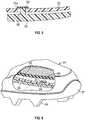
- the footwear 10is a cleated shoe and includes an upper 20 and a supporting sole structure 40 (which may be referred to herein as either "sole structure”, “sole assembly”, or “sole”) coupled to a lower area of the upper 20.
- the uppermay be coupled with the sole structure using any of one or more conventional techniques, such that the sole structure supports a wearer's foot during use.
- footwear 10may be considered to be divided into the three general regions; the forefoot region 10A, the midfoot region 10B, and the heel region 10C.
- the forefoot region 10Agenerally includes portions of footwear 10 positionally corresponding with forward portions of a user's foot during use, including the toes and the joints connecting the metatarsal bones with the phalangeal bones (interchangeably referred to as the "metatarsal-phalangeal joint", the “metatarsal-phalangeal joints", “MPJ”, or “MPJ” joints herein).
- the midfoot region 10Bextends between the forefoot region 10A and the heel region 10C, and generally includes portions of footwear 10 positionally corresponding with middle portions of a user's foot during use, including the foot's arch area.
- the heel region 10Cis disposed rearwardly from the midfoot region 10B, and generally includes portions of footwear 10 corresponding with rear portions of a user's foot, including the heel and calcaneus bone.
- longitudinalrefers to a direction extending along a length of the sole structure, e.g., from a forefoot portion to a heel portion of the sole structure.
- transverserefers to a direction extending along a width of the sole structure, e.g., from a lateral side to a medial side of the sole structure.
- forwardis used to refer to the general direction from the heel portion toward the forefoot portion, and the term “rearward” is used to refer to the opposite direction, i.e., the direction from the forefoot portion toward the heel portion.
- annularis used to refer to a front or forward component or portion of a component.
- Footwear 10also includes a lateral side 12 and a medial side 14, which correspond with opposite sides of the footwear 10 and extend through each of regions 10A-10C.
- the lateral side 12corresponds with an outside area of the foot, that is, the portion of a foot that faces away from the other foot.
- the medial side 14corresponds with an inside area of the foot, that is, the portion of a foot that faces toward the other foot.
- Regions 10A-10C and sides 12 and 14are not intended to demarcate precise areas of the footwear 10, but rather are intended to represent general areas of the footwear 10 to aid in the following discussion.
- the regions 10A-10C and sides 12 and 14may also be applied to portions of the footwear, including but not limited to the upper 20, the sole structure 40, and individual elements thereof.
- the upper 20can be configured in a similar manner, with regard to dimensions, shape, and materials, for example, as any conventional upper suitable to support, receive and retain a foot of a wearer; e.g., an athlete.
- the upper 20forms a void (also referred to as a foot-receiving cavity) configured to accommodate insertion of a user's foot, and to effectively secure the foot within the footwear 10 relative to an upper surface of the sole, or to otherwise unite the foot and the footwear 10.
- the upper 20includes an opening that provides a foot with access to the void, so that the foot may be inserted into and withdrawn from the upper 20 through the opening.
- the upper 20typically further includes one or more components suitable to further secure a user's foot proximate the sole structure, such as but not limited to a lace 26, a plurality of lace-receiving elements 28, and a tongue 30, as will be recognized by those skilled in the art.
- the upper 20can be formed of one or more layers, including for example one or more of a weather-resistant, a wear-resistant outer layer, a cushioning layer, and a lining layer.
- a weather-resistant, a wear-resistant outer layer, a cushioning layer, and a lining layermay be utilized. Accordingly, the features of upper 20 may vary considerably.
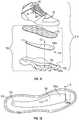
- a removable cushion member 53shown in FIG. 2 , may optionally be inserted into the upper 20 to provide additional wearer comfort, and in some embodiments, the cushion member 53 may comprise the insole. In other embodiments, an insole may be securely coupled to a portion of a foot-facing surface of the midsole.
- the sole structure 40 of the footwear 10extends between the foot and the ground to, for example, attenuate ground reaction forces to cushion the foot, provide traction, enhance stability, and influence the motions of the foot.
- the sole structure 40is coupled to the upper 20, the sole structure and upper can flex in cooperation with each other.
- the sole structure 40may be a unitary structure with a single layer that includes a ground-contacting element of the footwear, or the sole structure 40 may include multiple layers.
- a non-limiting exemplary multiple layer sole structuremay include three layers, referred to as an insole, a midsole, and an outsole for descriptive convenience herein.
- the insole 53may comprise a thin, comfort-enhancing member located adjacent to the foot.
- the midsoleforms the middle layer of the sole structure between the insole and the outsole, and serves a variety of purposes that may include controlling foot motions and shielding the foot from excessive ground reaction forces.
- the midsolecomprises a stiffness enhancing assembly 60, as shown in FIGS. 2 .
- the outsole 51comprises a ground-contacting element of the footwear, and is usually fashioned from a durable, wear resistant material. Examples of such materials can include, but are not limited to, nylon, thermoplastic polyurethane, carbon fiber, and others, as would be recognized by an ordinarily skilled artisan.
- Ground contacting elements of the outsole 51may include texturing or other traction features or elements, such as cleats 54, configured to improve traction with one or more types of ground surfaces (e.g., natural grass, artificial turf, asphalt pavement, dirt, etc.).
- the outsole 51may also be referred to as a plate.
- the exemplary embodiments hereindescribe and depict the stiffness enhancing assembly 60 and its stiffness enhancing features as a midsole, or a portion of a midsole, the embodiments include likewise configured stiffness enhancing assembly embodiments disposed either of an outsole or an insole, or as a portion of an outsole or of an insole.
- the embodimentsencompass embodiments wherein the stiffness enhancing assembly comprises a combination of an insole and a midsole, a combination of a midsole and an outsole, or as a combination of an insole, a midsole, and an outsole.
- one or more embodiments of the stiffness enhancing assemblyinclude one or more ground contacting elements disposed at, attached to, or projecting from its lower, ground-facing side.
- the stiffness enhancing assemblymay be part of either of a midsole, or an insole, or an outsole of the sole structure, or can comprise a combination of any two or more of the midsole, the insole, and the outsole.
- Various ones of the plates 62, 64, 102, 106 described hereinmay be an insole plate, also referred to as an insole, an inner board plate, inner board, insole board, or lasting board.
- the platescould be a midsole plate or a unisole plate, or may be one of, or a unitary combination of any two or more of, an outsole, a midsole, and/or an insole (also referred to as an inner board plate).
- an insole plate, or other layersmay overlay the plates between the plates and the foot.
- the stiffness enhancing assembly 60is at least partially secured to the outsole 51 and is positioned between the outsole 51 and the upper 20, or in the case where there is an insole and/or midsole between the outsole and the midsole or insole.
- the stiffness enhancing assembly 60provides a nonlinear bending stiffness along the flexion range, such that the outsole 51 and unrestricted stiffness enhancing assembly 60 have a first bending stiffness within the first portion of the flexion range of the sole structure, and outsole 51 and restricted stiffness enhancing assembly 60 have a seconding bend stiffness within the second portion of the flexion range of the sole structure.
- the second bending stiffnessis greater than the first bending stiffness.
- the second portion of the flexion rangeincludes flex angles greater than flex angles in the first portion of the flexion range.
- FIGS. 3-10provide an exemplary embodiment of the stiffness enhancing assembly 60 according to the present disclosure.
- the stiffness enhancing assembly 60includes a pair of stiffness enhancing members 62 and 64 that include at least a forefoot region 10A and that, in some embodiments, can extend between the forefoot region 10A and the heel region 10C of the sole structure 40, or between the forefoot region 10A and the midfoot region 10B of the sole structure 40.
- the stiffness enhancing members 62 and 64are plates (alternatively referred to herein as "plate member” or “plate members”).
- a platecan be but is not necessarily flat and need not be a single component but instead can be multiple interconnected components.
- a sole platemay be pre-formed with some amount of curvature and variations in thickness when molded or otherwise formed in order to provide a shaped footbed and/or increased thickness for reinforcement in desired areas.
- the sole platecould have a curved or contoured geometry that may be similar to the lower contours of the foot 52, and may have curves and contours similar to those in the outsole 51.
- the plate 62is referred to as a first plate, a first plate member, or a first one of the plates
- the plate 64is referred to as a second plate, a second plate member, or a second one of the plates.
- the plates 62 and 64may be dimensioned similar to the outsole 51, or the plates 62 and 64 may be dimensioned as a scaled version of the outsole 51.
- the plates 62 and 64are at least partially secured to the outsole 51, or to one another, via a connection feature 66, for example, so that the plates 62 and 64 are positioned between the outsole 51 and upper 20 (or between outsole and midsole or insole as noted above) to prevent longitudinal movement of one plate relative to the other plate at the connection feature 66.
- the connection via connection feature 66 between the plates and/or between the plates and another portion of the sole structure, such as the outsole 51can comprise any of a number of techniques or structures capable of securing the plates to each other, and/or securing the plates to each other and to the outsole 51, including for example, fasteners, adhesives, thermal bonding, and/or RF welds.
- the plates 62 and 64are secured together in the heel region 10C to prevent longitudinal movement of one plate (e.g., plate 62) relative to the other plate (e.g., plate 64) in the heel region.
- the plates 62 and 64can be secured together in the midfoot region 10B to prevent longitudinal movement of one plate (e.g., plate 62) relative to the other plate (e.g., plate 64) in the midfoot region.
- the plates 62 and 64can be secured together in the forefoot region 10A to prevent free-flow longitudinal movement of one plate (e.g., plate 62) relative to the other plate (e.g., plate 64) in the forefoot region.
- the stiffness enhancing members 62 and 64are secured to the outsole 51, or to one another, via a connection feature 66 in the heel region 10C, the stiffness enhancing member 62 has a slot 70 in the forefoot region 10A, and the stiffness enhancing member 64 has an abutment, which is at least partially vertical in the embodiment shown, such as the arm 68 extending from the forefoot region 10A.
- the stiffness enhancing members 62 and 64are positioned in a substantially parallel relationship to one another, with a ground-facing surface of stiffness enhancing member 62 confronting a foot-facing surface of stiffness enhancing member 64. Stated differently, the stiffness enhancing member 62 overlays the stiffness enhancing member 64.
- the arm 68 extending from one stiffness enhancing member (e.g., member 64)fits within the slot 70 in the other stiffness enhancing member (e.g., member 62), and optionally, a cap 69 maintains the arm 68 within the slot 70.
- the cap 69may be any structure capable of maintaining the arm 68 within the slot 70 while allowing relative movement of the arm 68 within the slot 70.
- the cap 69may be a press fit or threaded member that is larger in size than the arm 68, a fastener, or a widening of the arm 68, as shown in FIG. 5 .
- the stiffness enhancing memberse.g., plates 62 and 64, can be fashioned from a durable, wear resistant material that is sufficiently rigid to provide the bending stiffness described herein during the flexion range of the sole structure 40.
- durable, wear resistant materialsinclude nylon, thermoplastic polyurethane, carbon fiber, etc.
- the stiffness enhancing memberscan both be fashioned from the same durable, wear resistant material so that the stiffness properties of each stiffness enhancing member 62 and 64 is substantially the same.
- each of the stiffness enhancing memberscan be fashioned from a different durable, wear resistant material, to provide different stiffness properties. In either embodiment, the stiffness enhancing members 62, 64 together provide the nonlinear stiffness described herein.
- Either or both of the plates 62 and 64may be entirely of a single, uniform material, or may each have different portions comprising different materials that may be, for example, co-injection molded or over-molded.
- a first material of the forefoot regioncan be selected to achieve the desired bending stiffness in the forefoot region, while a second material of the midfoot region and the heel region can be a different material that has little effect on the bending stiffness of the forefoot region.
- the forefoot region of the outsole 51 and the stiffness enhancing assembly 60are flexible, being capable of bending in dorsiflexion throughout a range of flex angles.
- This flexion rangeis conceptually divided into two portions, with a change in bending stiffness occurring at a predetermined flex angle at the start of the second predetermined flexion range.
- a first portion of the flexion range(also referred to as a first range of flexion) includes flex angles during dorsiflexion of the sole structure from zero (i.e., an unflexed, relaxed state of the sole structure 40 and stiffness enhancing assembly 60, as seen in FIG.
- the forefoot region of the sole structure 40 including the stiffness enhancing assembly 60may be generally flat as shown in FIG. 7 , or alternatively, the forefoot region of the sole structure 40 including the stiffness enhancing assembly 60 may have a preformed curvature.
- a second portion of the flexion range(also referred to as a second range of flexion) includes flex angles of the sole structure 40 greater than or equal to the first predetermined flex angle A1, and begins as soon as the sole structure 40 is dorsiflexed to the first predetermined flex angle, and extends throughout greater flex angles with any further dorsiflexion of the sole structure 40 including the stiffness enhancing assembly 60 through progressively increasing angles of flexure greater than first predetermined flex angle A1.
- the arm 68is within the slot 70 such as at the forward end of the slot 70 as shown in FIG. 7a . Progressive dorsiflexion causes the position or the arm 68 within the slot 70 to change, moving toward the wall 70a, as indicated in FIGS.
- first contact between the arm 68 and wall 70a in slot 70conceptually demarcates the first predetermined flex angle.
- the first predetermined flex angle A1is defined as the angle formed at the intersection between a first axis generally extending along a longitudinal midline at a ground-facing surface of a posterior portion of the outsole 51 and a second axis generally extending along a longitudinal midline at the ground-facing surface of an anterior portion of the outsole 51.
- the intersection of the first and second axeswill typically be approximately centered both longitudinally and transversely relative to the stiffness enhancing assembly and under the MPJ joints.
- the numerical value of the first predetermined flex angle A1is dependent upon a number of factors, notably but non-exclusively, the dimension of the slot 70, and the particular structure of the stiffness enhancing assembly according to alternative embodiments, as will be discussed further below.
- the first predetermined flex angle A1is in the range of between about 30 degrees and about 60 degrees, with a typical value of about 55 degrees. In another exemplary embodiment, the first predetermined flex angle A1 is in the range of between about 15 degrees and about 30 degrees, with a typical value of about 25 degrees. In another example, the first predetermined flex angle A1 is in the range of between about 20 degrees and about 40 degrees, with a typical value of about 30 degrees.
- the first predetermined flex anglecan be any one of 35°, 36°, 37°, 38°, 39°, 40°, 41°, 42°, 43°, 44°, 45°, 46°, 47°, 48°, 49°, 50°, 51°, 52°, 53°, 54°, 55°, 56°, 57°, 58°, 59°, 60°, 61°, 62°, 63°, 64°, or 65°.
- the specific flex angle or range of angles at which a change in the rate of increase in bending stiffness occursis dependent upon the specific activity for which the article of footwear is designed.
- the stiffness enhancing assembly 60will bend in dorsiflexion in response to forces applied by corresponding bending of a user's foot at the MPJ during physical activity. Throughout the first portion of the flexion range FR1, the bending stiffness (defined as the change in moment as a function of the change in flex angle) will remain approximately the same as bending progresses through increasing angles of flexion.
- a graph of torque (or moment) on the stiffness enhancing assembly 60 versus angle of flexion (the slope of which is the bending stiffness) in the first portion of the flexion range FR1will typically demonstrate a smoothly but relatively gradually inclining curve (referred to herein as a "linear" region with constant bending stiffness).
- structures of the stiffness enhancing assembly 60engage, as described herein, such that additional material and mechanical properties exert a notable increase in resistance to further dorsiflexion.
- a corresponding graph of torque versus angle of flexion(the slope of which is the bending stiffness) that also includes the second portion of the flexion range FR2 would show - beginning at an angle of flexion approximately corresponding to angle A1 - a departure from the gradually and smoothly inclining curve characteristic of the first portion of the flexion range FR1.
- This departureis referred to herein as a "nonlinear" increase in bending stiffness, and would manifest as either or both of a stepwise increase in bending stiffness and/or a change in the rate of increase in the bending stiffness.
- the change in ratecan be either abrupt, or it can manifest over a short range of increase in the bend angle (i.e., also referred to as the flex angle or angle of flexion) of the stiffness enhancing assembly 60.
- a mathematical function describing a bending stiffness in the second portion of the flexion range FR2will differ from a mathematical function describing bending stiffness in the first portion of the flexion range.
- stiffness enhancing member 62slides relative to stiffness enhancing member 64 in the forefoot region.
- the slot 70 in stiffness enhancing member 62slides relative to arm 68 extending from stiffness enhancing member 64 (as seen in FIGS. 8, 8a , 9 and 9a ), from an anterior position toward a posterior position within the slot, such that relative longitudinal movement of the stiffness enhancing members is unrestricted.
- the arm 68is at roughly a midpoint within the slot 70.
- the arm 68is at the posterior end of the slot 70 such that the arm 68 is about to engage the wall 70a in slot 70.
- the point at which the arm 68 engages the wall 70a in slot 70is the beginning of the second portion of the flexion range of the sole structure.
- the outsole 51 and the stiffness enhancing members 62 and 64 restricted by the arm 68 engaging wall 70a in slot 70collectively provide the second bending stiffness of the sole structure 40.
- the stiffness enhancing members 62 and 64can be secured to the outsole 51 at a connection feature 66 in the forefoot region 10A at a point anterior to where the user's metatarsal-phalangeal joints would be supported on the sole structure.
- the stiffness enhancing member 62has a slot 70 in the heel region 10C, that receives the arm 68 extending from the stiffness enhancing member 64 in the heel region 10C.
- the arm 68 extending from stiffness enhancing member 64slides within slot 70 in stiffness enhancing member 62, such that the outsole 51 and unrestricted stiffness enhancing members collectively provide the first bending stiffness of the sole structure 40.
- the arm 68 extending from stiffness enhancing member 64engages a posterior wall of the slot 70 in stiffness enhancing member 62, restricting further relative motion of stiffness enhancing member 62 relative to stiffness enhancing member 64.
- the outsole 51 and restricted stiffness enhancing members 62 and 64collectively exert the second bend stiffness on the sole structure 40.
- the first bending stiffnessis at least partially correlated with the individual stiffnesses of the outsole 51 and stiffness enhancing members 62 and 64, plus other factors such as friction between the stiffness enhancing members 62 and 64, etc.
- the arm 68engages the wall of slot 70 and restricts further relative motion between the stiffness enhancing members 62 and 64.
- the stiffness enhancing member 62is subjected to compressive forces of the stiffness enhancing member 64 acting on the stiffness enhancing member 62 between the fixed connection feature 66 and the arm 68, and the stiffness enhancing member is subjected to additional tensile forces.
- the second bend stiffnessadditionally comprises stiffness enhancing member's 62 resistance to compression, and stiffness enhancing member's 64 resistance to elongation. These additional factors notably increase the second bending stiffness relative to the first bending stiffness.
- stiffness enhancing member's 62 resistance to compressionand stiffness enhancing member's 64 resistance to elongation.
- the operative engagement of the plates 62, 64places additional tension on the sole structure 40 below the neutral axis, such as at a bottom surface of the plate 64, effectively shifting the neutral axis of the sole structure 40 upward (away from the bottom surface).
- the operative engagement of the plates 62, 62places additional compressive forces on the sole structure above the neutral plane, and additional tensile forces below the neutral plane, nearer the ground-facing surface.
- structural factors that likewise affect changes in bending stiffness during dorsiflexioninclude but are not limited to the thicknesses, the longitudinal lengths, and the medial-lateral widths of different portions of the plates 62, 64.
- a transition from the first bend stiffness to the second bend stiffnessdemarcates a boundary between the first portion of the flexion range and the second portion of the flexion range.
- the materials and structures of the embodimentproceed through a range of increasing flexion, they may tend to increasingly resist further flexion. Therefore, a person having an ordinary level of skill in the relevant art will recognize in view of this specification and accompanying claims, that a stiffness of the sole structure throughout the first flexion range may not remain constant. Nonetheless, such resistance will generally increase linearly or progressively.
- the embodiments disclosed hereinprovide for a stepwise, nonlinear increase in resistance to flexion at the boundary between the first portion of the flexion range and the second portion of the flexion range.
- Providing a small separation distancewill result in a second bending stiffness occurring at a smaller flex angle (i.e., a smaller first predetermined flex angle A1), while providing a longer separation distance will result in a second bending stiffness occurring at a larger flex angle (i.e., a larger first predetermined flex angle A1).
- a person having an ordinary level of skill in the relevant artis enabled, in view of this specification and accompanying claims, to adjust such separation to achieve any of a wide range of relationships between a first portion of a flexion range and a second portion of a flexion.
- the slotmay be positioned in the stiffness enhancing member 64, and the arm 68 may extend from the stiffness enhancing member 62.
- the arm 68is configured to withstand forces (e.g., impact force, sheer force, etc.) applied when it engages the wall of the slot 70.
- the arm 68may be fashioned from the same durable, wear resistant material as the stiffness enhancing members, such as nylon or thermoplastic polyurethane, carbon fiber, etc.
- the arm 68may be fashioned from a different durable, wear-resistant material, such as Polyoxymethylene, a solid metal, a rigid polymer, or another suitable material as would be recognized by an ordinarily skilled artisan in view of this disclosure.
- FIGS. 11-16show another exemplary embodiment of an article of footwear 210 with a sole structure according to the present disclosure.
- the sole structure 100includes an outsole 102 and a stiffness enhancing assembly 104, both of which may be referred to as plates or plate members. More specifically, the stiffness enhancing member 104 may be referred to as a first plate or a first plate member, and the outsole 102 may be referred to as a second plate or a second plate member.
- the sole structure 100is similar to the sole structure 40, in that it may generally include multiple layers, i.e., an insole, a midsole, and an outsole. Generally, the insole is a thin, comfort-enhancing member located adjacent to the foot.
- the outsoleforms the ground-contacting element of footwear and is usually fashioned from a durable, wear resistant material, such as nylon or thermoplastic polyurethane, carbon fiber, etc., and the midsole forms the middle layer of the sole structure and serves a variety of purposes.
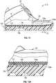
- the stiffness enhancing assembly 104 in this exemplary embodimentincludes a stiffness enhancing member 106, generally configured as a flattened, elongate plate (also referred to herein as a "plate” or “plate member”) disposed within a recess 108 in a foot-facing surface of the underlying portions of the sole structure, e.g., another plate such as the outsole 102. More specifically, the stiffness enhancing member 106 is referred to as a first plate, a first plate member, or a first one of the plates, and the outsole 102 is referred to as a second plate, a second plate member, or a second one of the plates.
- an upper surface of the stiffness enhancing member 106 and an upper surface of the outsole 102are approximately coplanar with each other, and collectively form a foot-facing surface of the sole structure.
- the stiffness enhancing member 106 and the recess 108may extend from the forefoot 10A of the outsole 102 to the heel region 10C of the outsole, as shown in FIG. 12 .
- the stiffness enhancing member 106 and the recess 108may extend from the forefoot 10A of the outsole 102 to the midfoot region 10B of the outsole 102 or, in another embodiment, only in the forefoot region 10A.
- the stiffness enhancing member 106overlays the outsole 102 and is secured to the outsole 102 at one or more connection features 110 and 112. Locating connection feature 112 more closely to an anterior portion 106a of the stiffness enhancing member 106 generally increases stiffness within at least the first portion of the flexion range, in contrast to when the connection feature 112 is located more distant from the anterior portion 106a, such as generally proximate a central portion 106b as shown in FIG. 12 , and/or proximate a more posterior portion 106c as shown by connection feature 110, of the stiffness enhancing member 106, by constraining bending to a shorter portion of the stiffness enhancing member 106.
- a slot in the stiffness enhancing member 106allows the stiffness enhancing member 106 to slide relative to the outsole 102 at connection feature 112, but connection feature 110 fixes the stiffness enhancing member 106 to the outsole 102 to prevent relative movement.
- the recess 108(labelled in FIG. A) is slightly larger than the stiffness enhancing member 106, so that the anterior portion 106a of the stiffness enhancing member 106 is spaced apart from an alternative vertical abutment, wall 108a in recess 108, by a distance "D" (or “gap").
- the distance “D”is in the range of, for example, between about 1 millimeter and about 5 millimeters.
- the stiffness enhancing member 106can be fashioned from a durable, wear resistant material that is sufficiently rigid such that the sole structure provides a suitable bending stiffness during the flexion range of the sole structure, as described herein. Examples, of such durable, wear resistant materials include nylon, thermoplastic polyurethane, carbon fiber, etc.
- the stiffness enhancing member 106can be fashioned from the same durable, wear resistant material as either the outsole 102, or the a midsole when the stiffness enhancing member is disposed within a recess in a midsole, etc., so that the stiffness of the outsole (or of the midsole) and the stiffness enhancing member 106 is substantially the same.
- the stiffness enhancing membercan be fashioned from a different durable, wear resistant material than the outsole 102, to provide a different level of stiffness than either of the outsole or the midsole.
- the sole structure 100provides a nonlinear stiffness such that the outsole 102 and the unrestricted stiffness enhancing member 106 collectively provide the first bending stiffness within the first portion of its flexion range.
- the outsole 102 and the restricted stiffness enhancing member 106collectively provide the second bend stiffness within the second portion of the flexion range of the sole structure.
- the second bending stiffnessis preferably greater than the first bend stiffness.
- the stiffness enhancing member 106is a plate positioned within the recess 108 in the outsole 102.
- the stiffness enhancing member 106In an unflexed, relaxed state, shown in FIGS. 13 and 13a , there is a space "D" between the anterior portion 106a of the stiffness enhancing member 106 and the anterior wall 108a of recess 108.
- the anterior portion 106a of the stiffness enhancing member 106slides relative to the outsole 102 within the recess 108 in the outsole, along a longitudinal axis of the footwear, such that the unrestricted stiffness enhancing member 106 and the outsole collectively provide the first bending stiffness of the sole structure 100.
- the anterior portion 106a of the stiffness enhancing member 106is at roughly a midpoint of the space "D", and in FIGS.
- the anterior portion of the stiffness enhancing member 106is at the anterior end of the recess 108 such that the anterior portion of the stiffness enhancing member 106 is about to engage the anterior wall 108a in recess 108.
- the flex angle at which the anterior portion of the stiffness enhancing member 106 engages the anterior wall 108a in recess 108is seen in FIGS. 16 and 16a , and is the beginning of the second portion of the flexion range of the sole structure.
- the anterior end of the stiffness enhancing member 106remains engaged with the anterior wall 108a of the recess 108, restricting further relative motion of the stiffness enhancing member 106 relative to the sole structure 100, including for example, outsole 102.
- the outsole 102provides a compressive force on stiffness enhancing member 106, and the stiffness enhancing member 106, restricted by the anterior portion 106a of the stiffness enhancing member 106 engaging the anterior wall 108a in recess 108, collectively provide the second bending stiffness of the sole structure 100.
Landscapes
- Chemical & Material Sciences (AREA)
- Engineering & Computer Science (AREA)
- Materials Engineering (AREA)
- Health & Medical Sciences (AREA)
- General Health & Medical Sciences (AREA)
- Physical Education & Sports Medicine (AREA)
- Footwear And Its Accessory, Manufacturing Method And Apparatuses (AREA)
Description
- This application claims the benefit of priority to United States Provisional Application No.
62/220633 filed September 18, 2015 62/220758 filed September 18, 2015 62/220638 filed September 18, 2015 62/220678 filed September 18, 2015 - The present teachings generally relate to an article of footwear and a sole structure for an article of footwear.
- Footwear typically includes a sole assembly configured to be located under a wearer's foot to space the foot away from the ground. Sole assemblies in athletic footwear are configured to provide desired cushioning, motion control, and resiliency.
FR 892 219 A FIG. 1 is a lateral side perspective view of an article of footwear according to an exemplary embodiment of the present disclosure.FIG. 2 is an exploded view of the footwear ofFIG. 1 .FIG. 3 is a lateral side perspective view of an exemplary embodiment of a stiffness enhancing assembly of the present disclosure.FIG. 4 is a fragmentary cross-sectional view of the stiffness enhancing assembly taken along line 4-4 ofFIG. 2 .FIG. 5 is a fragmentary cross-sectional view of the stiffness enhancing assembly taken along line 5-5 ofFIG. 2 .FIG. 6 is an enlarged fragmentary perspective view of a forefoot region of the footwear ofFIG. 1 .FIG. 7 is a lateral side elevation view of the footwear ofFIG. 1 , with the sole structure in an unflexed, relaxed position, including a partial sectional view of the stiffness enhancing assembly according to an exemplary embodiment.FIG. 7a is an enlarged fragmentary side elevation view of the forefoot region of the footwear ofFIG. 7 .FIG. 8 is a lateral side elevation view of the footwear ofFIG. 7 with the sole structure in a partially flexed condition.FIG. 8a is an enlarged fragmentary side elevation view of the forefoot region of the footwear ofFIG. 8 .FIG. 9 is a lateral side elevation view of the footwear ofFIG. 8 with the sole structure further flexed nearly to an end of a first portion of its flexion range.FIG. 9a is an enlarged fragmentary side elevation view of the forefoot region of the footwear ofFIG. 9 .FIG. 10 is a lateral side elevation view of the footwear ofFIG. 9 with the sole structure flexed to the end of the first portion of its flexion range.FIG. 10a is an enlarged fragmentary side elevation view of the forefoot region of the footwear ofFIG. 10 .FIG. 11 is a lateral side exploded perspective view of an article of footwear according to another exemplary embodiment of the present disclosure.FIG. 12 is a plan view of a stiffness enhancing assembly of according to another exemplary embodiment of the present disclosure.FIG. 13 is a lateral side elevation view of the footwear ofFIG. 11 with the sole structure in an unflexed, relaxed position, including a partial sectional view of the stiffness enhancing assembly according to another exemplary embodiment.FIG. 13a is an enlarged fragmentary side elevation view of the forefoot region of the footwear ofFIG. 13 .FIG. 14 is a lateral side elevation view of the footwear ofFIG. 13 with the sole structure in a partially flexed condition.FIG. 14a is an enlarged fragmentary side elevation view of the forefoot region of the footwear ofFIG. 14 .FIG. 15 is a lateral side elevation view of the footwear ofFIG. 14 with the sole structure further flexed nearly to an end of a first portion of its flexion range.FIG. 15a is an enlarged fragmentary side elevation view of the forefoot region of the footwear ofFIG. 15 .FIG. 16 is a lateral side elevation view of the footwear ofFIG. 15 with the sole structure flexed to a first predetermined flex angle.FIG. 16a is an enlarged fragmentary side elevation view of the forefoot region of the footwear ofFIG. 16 .- The invention is defined by a sole structure according to independent claim 1, while preferred embodiments form the subject of the dependent claims.
- The present disclosure generally provides a sole structure for footwear having a forefoot region, a heel region, and a midfoot region between the forefoot region and the heel region. The heel region may also be referred to as a rearfoot region. The forefoot region, the heel region, and the midfoot region are also referred to as the forefoot portion, the heel portion, and the midfoot portion, respectively. The footwear according to the present disclosure may be athletic footwear, such as football, soccer, or cross- training shoes, or the footwear may be for other activities, such as but not limited to other athletic activities. Embodiments of the footwear generally include an upper, and a sole structure coupled to the upper.
- More specifically, a sole structure for an article of footwear comprises a first plate and a second plate. The first plate overlies at least a portion of a forefoot region of the second plate. The first plate and the second plate are fixed to one another rearward of the forefoot region. The first plate is configured to slide longitudinally relative to the forefoot region of the second plate in a first portion of a flexion range during dorsiflexion of the sole structure, and to interfere with the second plate during a second portion of the flexion range that includes flex angles greater than in the first portion of the flexion range. The first portion of the flexion range includes flex angles of the sole structure less than a first predetermined flex angle. The second portion of the flexion range includes flex angles of the sole structure greater than or equal to the first predetermined flex angle. The sole structure has a change in bending stiffness at the first predetermined flex angle, thereby providing a nonlinear bending stiffness. Bending stiffness may also be referred to herein as bend stiffness. As used in this description and the accompanying claims, the phrase "bending stiffness" generally means a resistance to flexion of the sole structure exhibited by a material, structure, assembly of two or more components or a combination thereof, according to the disclosed embodiments. In a nonlimiting example, the first predetermined flex angle is an angle selected from the range of angles extending from 35 degrees to 65 degrees.
- In an embodiment, a connector feature fixes the first plate to the second plate and prevents relative movement between the first plate and the second plate at the connector feature. The connector feature is disposed in a midfoot region or a heel region of the second plate. The connector feature includes a protrusion in one of the first plate and the second plate, and the protrusion extends into another one of the first plate and the second plate.
- In an embodiment, a first one of the first plate and the second plate has an abutment spaced longitudinally apart from the connector feature. A second one of the first plate and the second plate has a confronting surface. The abutment and the confronting surface are spaced apart from one another by a gap when the sole structure is in an unflexed, relaxed state, and are in contact with one another during the second portion of the flexion range.
- In an embodiment, the second one of the first plate and the second plate has a slot, and the confronting surface is a wall of the first one of the first plate and the second plate bounding the slot. The abutment extends into the slot. Dorsiflexion of the sole structure in the first portion of the flexion ranges changes a position of the abutment in the slot.
- In an embodiment, the second plate has a foot-facing surface with a recess in the foot-facing surface. The first plate is disposed in the recess. The confronting surface is an anterior end of the first plate. The abutment is a wall of the second plate at an anterior end of the recess. The gap is in the recess between the anterior end of the first plate and the wall. The wall may be perpendicular to the foot-facing surface, but is not limited to such an orientation. Additionally, an upper surface of the first plate and the foot-facing surface of the second plate may be coplanar.
- In an example embodiment, the second plate is an outsole. In another example embodiment, the sole structure includes an outsole and the second plate is between first plate and outsole. In an example embodiment, the first plate extends at least from the forefoot region of the second plate to a midfoot region of the second plate. In another example embodiment, the first plate extends at least from the forefoot region of the second plate to a heel region of the second plate.
- In an embodiment, a sole structure for an article of footwear comprises a first plate and a second plate. The first plate overlies at least a portion of a forefoot region of the second plate. A connector feature connects the first plate to the second plate and prevents relative movement between the first plate and the second plate at the connector feature. A first one of the first plate and the second plate has an abutment spaced longitudinally apart from the connector feature. A second one of the first plate and the second plate has a confronting surface. The abutment and the confronting surface are spaced apart from one another by a gap when the sole structure is in an unflexed, relaxed state. Dorsiflexion of the sole structure causes longitudinal displacement of the first plate relative to the second plate at the gap until the first plate operatively engages with the second plate by the confronting surface contacting the abutment, such that the first plate flexes free of compressive loading by the second plate when a forefoot portion of the sole structure is dorsiflexed in a first portion of a flexion range, and is operatively engaged with and under compressive loading by the second plate when the forefoot portion of the sole structure is dorsiflexed in a second portion of the flexion range that includes flex angles greater than in the first portion of the flexion range. The first portion of the flexion range includes flex angles of the sole structure less than a first predetermined flex angle. The second portion of the flexion range includes flex angles of the sole structure greater than or equal to the first predetermined flex angle. The sole structure has a change in bending stiffness at the first predetermined flex angle.
- In an embodiment, the connector feature is in a midfoot region or in a heel region of the second plate, the first plate has a slot in a forefoot region of the first plate, the second plate has an arm in the forefoot region of the second plate that extends into the slot, a position of the arm in the slot changes in the first portion of the flexion range, and the arm interferes with the second plate at the end of the slot in the second portion of the flexion range. In an embodiment, the second plate has a foot-facing surface with a recess in the foot-facing surface, the first plate is disposed in the recess, and an anterior end of the first plate contacts a wall of the second plate at an anterior end of the recess in the second portion of the flexion range.
- The above features and advantages and other features and advantages of the present teachings are readily apparent from the following detailed description of the modes for carrying out the present teachings when taken in connection with the accompanying drawings.
- "A," "an," "the," "at least one," and "one or more" are used interchangeably to indicate that at least one of the items is present. A plurality of such items may be present unless the context clearly indicates otherwise. All numerical values of parameters (e.g., of quantities or conditions) in this specification, unless otherwise indicated expressly or clearly in view of the context, including the appended claims, are to be understood as being modified in all instances by the term "about" whether or not "about" actually appears before the numerical value. "About" indicates that the stated numerical value allows some slight imprecision (with some approach to exactness in the value; approximately or reasonably close to the value; nearly). If the imprecision provided by "about" is not otherwise understood in the art with this ordinary meaning, then "about" as used herein indicates at least variations that may arise from ordinary methods of measuring and using such parameters. In addition, a disclosure of a range is to be understood as specifically disclosing all values and further divided ranges within the range.
- The terms "comprising," "including," and "having" are inclusive and therefore specify the presence of stated features, steps, operations, elements, or components, but do not preclude the presence or addition of one or more other features, steps, operations, elements, or components. As used in this specification, the term "or" includes any one and all combinations of the associated listed items. The term "any of' is understood to include any possible combination of referenced items, including "any one of' the referenced items. The term "any of' is understood to include any possible combination of referenced claims of the appended claims, including "any one of' the referenced claims.
- Those having ordinary skill in the art will recognize that terms such as "above," "below," "upward," "downward," "top," "bottom," etc., are used descriptively relative to the figures, and do not represent limitations on the scope of the invention, as defined by the claims.
- Referring to the drawings, wherein like reference numbers refer to like components throughout the views, an exemplary embodiment of an article of
footwear 10 according to the present disclosure is shown inFIGS. 1 and 2 . In this exemplary embodiment, thefootwear 10 is a cleated shoe and includes an upper 20 and a supporting sole structure 40 (which may be referred to herein as either "sole structure", "sole assembly", or "sole") coupled to a lower area of the upper 20. The upper may be coupled with the sole structure using any of one or more conventional techniques, such that the sole structure supports a wearer's foot during use. For descriptive convenience,footwear 10 may be considered to be divided into the three general regions; theforefoot region 10A, themidfoot region 10B, and theheel region 10C. Theforefoot region 10A generally includes portions offootwear 10 positionally corresponding with forward portions of a user's foot during use, including the toes and the joints connecting the metatarsal bones with the phalangeal bones (interchangeably referred to as the "metatarsal-phalangeal joint", the "metatarsal-phalangeal joints", "MPJ", or "MPJ" joints herein). Themidfoot region 10B extends between theforefoot region 10A and theheel region 10C, and generally includes portions offootwear 10 positionally corresponding with middle portions of a user's foot during use, including the foot's arch area. Theheel region 10C is disposed rearwardly from themidfoot region 10B, and generally includes portions offootwear 10 corresponding with rear portions of a user's foot, including the heel and calcaneus bone. - The term "longitudinal," as used herein, refers to a direction extending along a length of the sole structure, e.g., from a forefoot portion to a heel portion of the sole structure. The term "transverse," as used herein, refers to a direction extending along a width of the sole structure, e.g., from a lateral side to a medial side of the sole structure. The term "forward" is used to refer to the general direction from the heel portion toward the forefoot portion, and the term "rearward" is used to refer to the opposite direction, i.e., the direction from the forefoot portion toward the heel portion. The term "anterior" is used to refer to a front or forward component or portion of a component.
Footwear 10 also includes alateral side 12 and amedial side 14, which correspond with opposite sides of thefootwear 10 and extend through each ofregions 10A-10C. Thelateral side 12 corresponds with an outside area of the foot, that is, the portion of a foot that faces away from the other foot. Themedial side 14 corresponds with an inside area of the foot, that is, the portion of a foot that faces toward the other foot.Regions 10A-10C andsides footwear 10, but rather are intended to represent general areas of thefootwear 10 to aid in the following discussion. In addition tofootwear 10, theregions 10A-10C andsides sole structure 40, and individual elements thereof.- The upper 20 can be configured in a similar manner, with regard to dimensions, shape, and materials, for example, as any conventional upper suitable to support, receive and retain a foot of a wearer; e.g., an athlete. The upper 20 forms a void (also referred to as a foot-receiving cavity) configured to accommodate insertion of a user's foot, and to effectively secure the foot within the
footwear 10 relative to an upper surface of the sole, or to otherwise unite the foot and thefootwear 10. In the embodiment shown, the upper 20 includes an opening that provides a foot with access to the void, so that the foot may be inserted into and withdrawn from the upper 20 through the opening. The upper 20 typically further includes one or more components suitable to further secure a user's foot proximate the sole structure, such as but not limited to alace 26, a plurality of lace-receivingelements 28, and atongue 30, as will be recognized by those skilled in the art. - The upper 20 can be formed of one or more layers, including for example one or more of a weather-resistant, a wear-resistant outer layer, a cushioning layer, and a lining layer. Although the above described configuration for the upper 20 provides an example of an upper that may be used in connection with embodiments of the
sole structure 40 andstiffness enhancing assembly 60, a variety of other conventional or nonconventional configurations for the upper may also be utilized. Accordingly, the features of upper 20 may vary considerably. Further, aremovable cushion member 53, shown inFIG. 2 , may optionally be inserted into the upper 20 to provide additional wearer comfort, and in some embodiments, thecushion member 53 may comprise the insole. In other embodiments, an insole may be securely coupled to a portion of a foot-facing surface of the midsole. - The
sole structure 40 of thefootwear 10 extends between the foot and the ground to, for example, attenuate ground reaction forces to cushion the foot, provide traction, enhance stability, and influence the motions of the foot. When thesole structure 40 is coupled to the upper 20, the sole structure and upper can flex in cooperation with each other. - Referring to
FIG. 2 , thesole structure 40 may be a unitary structure with a single layer that includes a ground-contacting element of the footwear, or thesole structure 40 may include multiple layers. For example, a non-limiting exemplary multiple layer sole structure may include three layers, referred to as an insole, a midsole, and an outsole for descriptive convenience herein. Theinsole 53 may comprise a thin, comfort-enhancing member located adjacent to the foot. The midsole forms the middle layer of the sole structure between the insole and the outsole, and serves a variety of purposes that may include controlling foot motions and shielding the foot from excessive ground reaction forces. In one or more of the disclosed embodiments, the midsole comprises astiffness enhancing assembly 60, as shown inFIGS. 2 . Theoutsole 51 comprises a ground-contacting element of the footwear, and is usually fashioned from a durable, wear resistant material. Examples of such materials can include, but are not limited to, nylon, thermoplastic polyurethane, carbon fiber, and others, as would be recognized by an ordinarily skilled artisan. Ground contacting elements of theoutsole 51 may include texturing or other traction features or elements, such ascleats 54, configured to improve traction with one or more types of ground surfaces (e.g., natural grass, artificial turf, asphalt pavement, dirt, etc.). Theoutsole 51 may also be referred to as a plate. Although the exemplary embodiments herein describe and depict thestiffness enhancing assembly 60 and its stiffness enhancing features as a midsole, or a portion of a midsole, the embodiments include likewise configured stiffness enhancing assembly embodiments disposed either of an outsole or an insole, or as a portion of an outsole or of an insole. Likewise, the embodiments encompass embodiments wherein the stiffness enhancing assembly comprises a combination of an insole and a midsole, a combination of a midsole and an outsole, or as a combination of an insole, a midsole, and an outsole. When configured as an outsole or outsole portion, one or more embodiments of the stiffness enhancing assembly include one or more ground contacting elements disposed at, attached to, or projecting from its lower, ground-facing side. The stiffness enhancing assembly may be part of either of a midsole, or an insole, or an outsole of the sole structure, or can comprise a combination of any two or more of the midsole, the insole, and the outsole. Various ones of theplates - In the embodiment of
FIGS. 3-10 , thestiffness enhancing assembly 60 is at least partially secured to theoutsole 51 and is positioned between theoutsole 51 and the upper 20, or in the case where there is an insole and/or midsole between the outsole and the midsole or insole. Thestiffness enhancing assembly 60 provides a nonlinear bending stiffness along the flexion range, such that theoutsole 51 and unrestrictedstiffness enhancing assembly 60 have a first bending stiffness within the first portion of the flexion range of the sole structure, andoutsole 51 and restrictedstiffness enhancing assembly 60 have a seconding bend stiffness within the second portion of the flexion range of the sole structure. The second bending stiffness is greater than the first bending stiffness. The second portion of the flexion range includes flex angles greater than flex angles in the first portion of the flexion range. FIGS. 3-10 provide an exemplary embodiment of thestiffness enhancing assembly 60 according to the present disclosure. In this exemplary embodiment, thestiffness enhancing assembly 60 includes a pair ofstiffness enhancing members forefoot region 10A and that, in some embodiments, can extend between theforefoot region 10A and theheel region 10C of thesole structure 40, or between theforefoot region 10A and themidfoot region 10B of thesole structure 40. In the embodiment shown inFIGS. 3-10 , thestiffness enhancing members outsole 51. More specifically, theplate 62 is referred to as a first plate, a first plate member, or a first one of the plates, and theplate 64 is referred to as a second plate, a second plate member, or a second one of the plates. Theplates outsole 51, or theplates outsole 51.- The
plates outsole 51, or to one another, via aconnection feature 66, for example, so that theplates outsole 51 and upper 20 (or between outsole and midsole or insole as noted above) to prevent longitudinal movement of one plate relative to the other plate at theconnection feature 66. The connection viaconnection feature 66 between the plates and/or between the plates and another portion of the sole structure, such as theoutsole 51, can comprise any of a number of techniques or structures capable of securing the plates to each other, and/or securing the plates to each other and to theoutsole 51, including for example, fasteners, adhesives, thermal bonding, and/or RF welds. In one embodiment, theplates heel region 10C to prevent longitudinal movement of one plate (e.g., plate 62) relative to the other plate (e.g., plate 64) in the heel region. In another embodiment, theplates midfoot region 10B to prevent longitudinal movement of one plate (e.g., plate 62) relative to the other plate (e.g., plate 64) in the midfoot region. In another embodiment, theplates forefoot region 10A to prevent free-flow longitudinal movement of one plate (e.g., plate 62) relative to the other plate (e.g., plate 64) in the forefoot region. In the exemplary embodiment shown inFIG. 3 , thestiffness enhancing members outsole 51, or to one another, via aconnection feature 66 in theheel region 10C, thestiffness enhancing member 62 has aslot 70 in theforefoot region 10A, and thestiffness enhancing member 64 has an abutment, which is at least partially vertical in the embodiment shown, such as thearm 68 extending from theforefoot region 10A. - The
stiffness enhancing members stiffness enhancing member 62 confronting a foot-facing surface ofstiffness enhancing member 64. Stated differently, thestiffness enhancing member 62 overlays thestiffness enhancing member 64. Thearm 68 extending from one stiffness enhancing member (e.g., member 64) fits within theslot 70 in the other stiffness enhancing member (e.g., member 62), and optionally, acap 69 maintains thearm 68 within theslot 70. Thecap 69 may be any structure capable of maintaining thearm 68 within theslot 70 while allowing relative movement of thearm 68 within theslot 70. For example, thecap 69 may be a press fit or threaded member that is larger in size than thearm 68, a fastener, or a widening of thearm 68, as shown inFIG. 5 . - The stiffness enhancing members, e.g.,
plates sole structure 40. Examples, of such durable, wear resistant materials include nylon, thermoplastic polyurethane, carbon fiber, etc. The stiffness enhancing members can both be fashioned from the same durable, wear resistant material so that the stiffness properties of eachstiffness enhancing member stiffness enhancing members plates - For the purpose of the present disclosure, the forefoot region of the
outsole 51 and thestiffness enhancing assembly 60 are flexible, being capable of bending in dorsiflexion throughout a range of flex angles. This flexion range is conceptually divided into two portions, with a change in bending stiffness occurring at a predetermined flex angle at the start of the second predetermined flexion range. A first portion of the flexion range (also referred to as a first range of flexion) includes flex angles during dorsiflexion of the sole structure from zero (i.e., an unflexed, relaxed state of thesole structure 40 andstiffness enhancing assembly 60, as seen inFIG. 7 for example), to any flex angle less than the first predetermined flex angle (defined as angle A1 when theplate 62 operatively engages with the plate 64 (i.e., when thearm 68 engageswall 70a in slot 70), seen inFIGS. 10 and 10a . It is noted that when in the unflexed position, the forefoot region of thesole structure 40 including thestiffness enhancing assembly 60 may be generally flat as shown inFIG. 7 , or alternatively, the forefoot region of thesole structure 40 including thestiffness enhancing assembly 60 may have a preformed curvature. A second portion of the flexion range (also referred to as a second range of flexion) includes flex angles of thesole structure 40 greater than or equal to the first predetermined flex angle A1, and begins as soon as thesole structure 40 is dorsiflexed to the first predetermined flex angle, and extends throughout greater flex angles with any further dorsiflexion of thesole structure 40 including thestiffness enhancing assembly 60 through progressively increasing angles of flexure greater than first predetermined flex angle A1. In the first portion of the flexion range, thearm 68 is within theslot 70 such as at the forward end of theslot 70 as shown inFIG. 7a . Progressive dorsiflexion causes the position or thearm 68 within theslot 70 to change, moving toward thewall 70a, as indicated inFIGS. 8a ,9a , and10a , until thearm 68 contacts thewall 70a at the first predetermined flex angle A1. Therefore, as used within this description, first contact between thearm 68 andwall 70a inslot 70 conceptually demarcates the first predetermined flex angle. - The first predetermined flex angle A1 is defined as the angle formed at the intersection between a first axis generally extending along a longitudinal midline at a ground-facing surface of a posterior portion of the
outsole 51 and a second axis generally extending along a longitudinal midline at the ground-facing surface of an anterior portion of theoutsole 51. The intersection of the first and second axes will typically be approximately centered both longitudinally and transversely relative to the stiffness enhancing assembly and under the MPJ joints. The numerical value of the first predetermined flex angle A1 is dependent upon a number of factors, notably but non-exclusively, the dimension of theslot 70, and the particular structure of the stiffness enhancing assembly according to alternative embodiments, as will be discussed further below. - In one exemplary embodiment, the first predetermined flex angle A1 is in the range of between about 30 degrees and about 60 degrees, with a typical value of about 55 degrees. In another exemplary embodiment, the first predetermined flex angle A1 is in the range of between about 15 degrees and about 30 degrees, with a typical value of about 25 degrees. In another example, the first predetermined flex angle A1 is in the range of between about 20 degrees and about 40 degrees, with a typical value of about 30 degrees. In particular, the first predetermined flex angle can be any one of 35°, 36°, 37°, 38°, 39°, 40°, 41°, 42°, 43°, 44°, 45°, 46°, 47°, 48°, 49°, 50°, 51°, 52°, 53°, 54°, 55°, 56°, 57°, 58°, 59°, 60°, 61°, 62°, 63°, 64°, or 65°. Generally, the specific flex angle or range of angles at which a change in the rate of increase in bending stiffness occurs is dependent upon the specific activity for which the article of footwear is designed.
- As an ordinarily skilled artisan will recognize in view of the present disclosure, the
stiffness enhancing assembly 60 will bend in dorsiflexion in response to forces applied by corresponding bending of a user's foot at the MPJ during physical activity. Throughout the first portion of the flexion range FR1, the bending stiffness (defined as the change in moment as a function of the change in flex angle) will remain approximately the same as bending progresses through increasing angles of flexion. Because bending within the first portion of the flexion range FR1 is primarily governed by inherent material properties of the materials of thestiffness enhancing assembly 60, a graph of torque (or moment) on thestiffness enhancing assembly 60 versus angle of flexion (the slope of which is the bending stiffness) in the first portion of the flexion range FR1 will typically demonstrate a smoothly but relatively gradually inclining curve (referred to herein as a "linear" region with constant bending stiffness). At the boundary between the first and second portions of the range of flexion, however, structures of thestiffness enhancing assembly 60 engage, as described herein, such that additional material and mechanical properties exert a notable increase in resistance to further dorsiflexion. Therefore, a corresponding graph of torque versus angle of flexion (the slope of which is the bending stiffness) that also includes the second portion of the flexion range FR2 would show - beginning at an angle of flexion approximately corresponding to angle A1 - a departure from the gradually and smoothly inclining curve characteristic of the first portion of the flexion range FR1. This departure is referred to herein as a "nonlinear" increase in bending stiffness, and would manifest as either or both of a stepwise increase in bending stiffness and/or a change in the rate of increase in the bending stiffness. The change in rate can be either abrupt, or it can manifest over a short range of increase in the bend angle (i.e., also referred to as the flex angle or angle of flexion) of thestiffness enhancing assembly 60. In either case, a mathematical function describing a bending stiffness in the second portion of the flexion range FR2 will differ from a mathematical function describing bending stiffness in the first portion of the flexion range. - In the configuration of
FIGS. 3-10a , and starting from an unflexed, relaxed position, seen inFIGS. 7 and 7a , when thesole structure 40 is flexed within the first portion of its flexion range,stiffness enhancing member 62 slides relative tostiffness enhancing member 64 in the forefoot region. Correspondingly, theslot 70 instiffness enhancing member 62 slides relative toarm 68 extending from stiffness enhancing member 64 (as seen inFIGS. 8, 8a ,9 and 9a ), from an anterior position toward a posterior position within the slot, such that relative longitudinal movement of the stiffness enhancing members is unrestricted. InFIGS. 8 and 8a , thearm 68 is at roughly a midpoint within theslot 70. InFIGS. 9 and 9a thearm 68 is at the posterior end of theslot 70 such that thearm 68 is about to engage thewall 70a inslot 70. The point at which thearm 68 engages thewall 70a inslot 70, seen inFIGS. 10 and 10a , is the beginning of the second portion of the flexion range of the sole structure. Throughout the second portion of the flexion range of the sole structure, theoutsole 51 and thestiffness enhancing members arm 68engaging wall 70a inslot 70 collectively provide the second bending stiffness of thesole structure 40. - In another exemplary embodiment, the
stiffness enhancing members outsole 51 at aconnection feature 66 in theforefoot region 10A at a point anterior to where the user's metatarsal-phalangeal joints would be supported on the sole structure. Thestiffness enhancing member 62 has aslot 70 in theheel region 10C, that receives thearm 68 extending from thestiffness enhancing member 64 in theheel region 10C. In this exemplary embodiment, when thesole structure 40 is flexed within the first portion of its flexion range, thearm 68 extending fromstiffness enhancing member 64 slides withinslot 70 instiffness enhancing member 62, such that theoutsole 51 and unrestricted stiffness enhancing members collectively provide the first bending stiffness of thesole structure 40. When thesole structure 40 is further flexed to the end of the first portion of its flexion range, thearm 68 extending fromstiffness enhancing member 64 engages a posterior wall of theslot 70 instiffness enhancing member 62, restricting further relative motion ofstiffness enhancing member 62 relative tostiffness enhancing member 64. Throughout the second portion of the flexion range of the sole structure, theoutsole 51 and restrictedstiffness enhancing members sole structure 40. - Throughout the first portion of the flexion range, the first bending stiffness is at least partially correlated with the individual stiffnesses of the
outsole 51 andstiffness enhancing members stiffness enhancing members arm 68 engages the wall ofslot 70 and restricts further relative motion between thestiffness enhancing members stiffness enhancing member 62 is subjected to compressive forces of thestiffness enhancing member 64 acting on thestiffness enhancing member 62 between the fixedconnection feature 66 and thearm 68, and the stiffness enhancing member is subjected to additional tensile forces. Accordingly, the second bend stiffness additionally comprises stiffness enhancing member's 62 resistance to compression, and stiffness enhancing member's 64 resistance to elongation. These additional factors notably increase the second bending stiffness relative to the first bending stiffness. As will be understood by those skilled in the art, during bending of thesole structure 40 as the foot is dorsiflexed, there is a neutral axis of the sole structure above which the sole structure is in compression, and below which the sole structure is in tension. The operative engagement of theplates 62, 64 (i.e., when thearm 68 contacts the wall of theplate 62 at the end of the slot 70) places additional tension on thesole structure 40 below the neutral axis, such as at a bottom surface of theplate 64, effectively shifting the neutral axis of thesole structure 40 upward (away from the bottom surface). The operative engagement of theplates plates - As described herein, a transition from the first bend stiffness to the second bend stiffness demarcates a boundary between the first portion of the flexion range and the second portion of the flexion range. As the materials and structures of the embodiment proceed through a range of increasing flexion, they may tend to increasingly resist further flexion. Therefore, a person having an ordinary level of skill in the relevant art will recognize in view of this specification and accompanying claims, that a stiffness of the sole structure throughout the first flexion range may not remain constant. Nonetheless, such resistance will generally increase linearly or progressively. By contrast, the embodiments disclosed herein provide for a stepwise, nonlinear increase in resistance to flexion at the boundary between the first portion of the flexion range and the second portion of the flexion range.
- An amount of separation between a posterior wall of
slot 70 and a posterior surface ofarm 68, while the sole structure is in a relaxed, unflexed condition, affects an amount of flexion that a sole structure will achieve throughout the first portion of the flexion range before transitioning to the second portion of the flexion range. Providing a small separation distance will result in a second bending stiffness occurring at a smaller flex angle (i.e., a smaller first predetermined flex angle A1), while providing a longer separation distance will result in a second bending stiffness occurring at a larger flex angle (i.e., a larger first predetermined flex angle A1). A person having an ordinary level of skill in the relevant art is enabled, in view of this specification and accompanying claims, to adjust such separation to achieve any of a wide range of relationships between a first portion of a flexion range and a second portion of a flexion. - While the above describes the slot in
stiffness enhancing member 62 and thearm 68 extending fromstiffness enhancing member 64, one skilled in the art would readily recognize that the slot may be positioned in thestiffness enhancing member 64, and thearm 68 may extend from thestiffness enhancing member 62. In either configuration, thearm 68 is configured to withstand forces (e.g., impact force, sheer force, etc.) applied when it engages the wall of theslot 70. For example, thearm 68 may be fashioned from the same durable, wear resistant material as the stiffness enhancing members, such as nylon or thermoplastic polyurethane, carbon fiber, etc. Alternatively, thearm 68 may be fashioned from a different durable, wear-resistant material, such as Polyoxymethylene, a solid metal, a rigid polymer, or another suitable material as would be recognized by an ordinarily skilled artisan in view of this disclosure. FIGS. 11-16 show another exemplary embodiment of an article offootwear 210 with a sole structure according to the present disclosure. In this exemplary embodiment, thesole structure 100 includes anoutsole 102 and astiffness enhancing assembly 104, both of which may be referred to as plates or plate members. More specifically, thestiffness enhancing member 104 may be referred to as a first plate or a first plate member, and theoutsole 102 may be referred to as a second plate or a second plate member. As described in more detail above, thesole structure 100 is similar to thesole structure 40, in that it may generally include multiple layers, i.e., an insole, a midsole, and an outsole. Generally, the insole is a thin, comfort-enhancing member located adjacent to the foot. The outsole forms the ground-contacting element of footwear and is usually fashioned from a durable, wear resistant material, such as nylon or thermoplastic polyurethane, carbon fiber, etc., and the midsole forms the middle layer of the sole structure and serves a variety of purposes.- The
stiffness enhancing assembly 104 in this exemplary embodiment includes astiffness enhancing member 106, generally configured as a flattened, elongate plate (also referred to herein as a "plate" or "plate member") disposed within arecess 108 in a foot-facing surface of the underlying portions of the sole structure, e.g., another plate such as theoutsole 102. More specifically, thestiffness enhancing member 106 is referred to as a first plate, a first plate member, or a first one of the plates, and theoutsole 102 is referred to as a second plate, a second plate member, or a second one of the plates. In an exemplary embodiment, an upper surface of thestiffness enhancing member 106 and an upper surface of theoutsole 102 are approximately coplanar with each other, and collectively form a foot-facing surface of the sole structure. Thestiffness enhancing member 106 and therecess 108 may extend from theforefoot 10A of theoutsole 102 to theheel region 10C of the outsole, as shown inFIG. 12 . In another embodiment, thestiffness enhancing member 106 and therecess 108 may extend from theforefoot 10A of theoutsole 102 to themidfoot region 10B of theoutsole 102 or, in another embodiment, only in theforefoot region 10A. - The
stiffness enhancing member 106 overlays theoutsole 102 and is secured to theoutsole 102 at one or more connection features 110 and 112. Locating connection feature 112 more closely to ananterior portion 106a of thestiffness enhancing member 106 generally increases stiffness within at least the first portion of the flexion range, in contrast to when theconnection feature 112 is located more distant from theanterior portion 106a, such as generally proximate a central portion 106b as shown inFIG. 12 , and/or proximate a more posterior portion 106c as shown byconnection feature 110, of thestiffness enhancing member 106, by constraining bending to a shorter portion of thestiffness enhancing member 106. As is evident in the figures, a slot in thestiffness enhancing member 106 allows thestiffness enhancing member 106 to slide relative to theoutsole 102 atconnection feature 112, but connection feature 110 fixes thestiffness enhancing member 106 to theoutsole 102 to prevent relative movement. - As can be seen in
FIG. 12 , the recess 108 (labelled in FIG. A) is slightly larger than thestiffness enhancing member 106, so that theanterior portion 106a of thestiffness enhancing member 106 is spaced apart from an alternative vertical abutment,wall 108a inrecess 108, by a distance "D" (or "gap"). The distance "D" is in the range of, for example, between about 1 millimeter and about 5 millimeters. - The
stiffness enhancing member 106 can be fashioned from a durable, wear resistant material that is sufficiently rigid such that the sole structure provides a suitable bending stiffness during the flexion range of the sole structure, as described herein. Examples, of such durable, wear resistant materials include nylon, thermoplastic polyurethane, carbon fiber, etc. Thestiffness enhancing member 106 can be fashioned from the same durable, wear resistant material as either theoutsole 102, or the a midsole when the stiffness enhancing member is disposed within a recess in a midsole, etc., so that the stiffness of the outsole (or of the midsole) and thestiffness enhancing member 106 is substantially the same. Alternatively, the stiffness enhancing member can be fashioned from a different durable, wear resistant material than theoutsole 102, to provide a different level of stiffness than either of the outsole or the midsole. - In this exemplary embodiment, the
sole structure 100 provides a nonlinear stiffness such that theoutsole 102 and the unrestrictedstiffness enhancing member 106 collectively provide the first bending stiffness within the first portion of its flexion range. When thesole structure 100 is further flexed to the end of the first portion of its flexion range, theoutsole 102 and the restrictedstiffness enhancing member 106 collectively provide the second bend stiffness within the second portion of the flexion range of the sole structure. The second bending stiffness is preferably greater than the first bend stiffness. - More specifically, in the exemplary embodiment of
FIGS. 11-16 , thestiffness enhancing member 106 is a plate positioned within therecess 108 in theoutsole 102. In an unflexed, relaxed state, shown inFIGS. 13 and 13a , there is a space "D" between theanterior portion 106a of thestiffness enhancing member 106 and theanterior wall 108a ofrecess 108. During the first portion of the flexion range of the sole structure 100 (seen inFIGS. 14, 14a ,15 and 15a ), theanterior portion 106a of thestiffness enhancing member 106 slides relative to theoutsole 102 within therecess 108 in the outsole, along a longitudinal axis of the footwear, such that the unrestrictedstiffness enhancing member 106 and the outsole collectively provide the first bending stiffness of thesole structure 100. InFIGS. 14 and 14a , theanterior portion 106a of thestiffness enhancing member 106 is at roughly a midpoint of the space "D", and inFIGS. 15 and 15a the anterior portion of thestiffness enhancing member 106 is at the anterior end of therecess 108 such that the anterior portion of thestiffness enhancing member 106 is about to engage theanterior wall 108a inrecess 108. The flex angle at which the anterior portion of thestiffness enhancing member 106 engages theanterior wall 108a inrecess 108 is seen inFIGS. 16 and 16a , and is the beginning of the second portion of the flexion range of the sole structure. When thesole structure 100 is flexed into the second portion of its flexion range (seen inFIG. 16 ), the anterior end of thestiffness enhancing member 106 remains engaged with theanterior wall 108a of therecess 108, restricting further relative motion of thestiffness enhancing member 106 relative to thesole structure 100, including for example,outsole 102. Throughout the second portion of the flexion range of the sole structure, theoutsole 102 provides a compressive force onstiffness enhancing member 106, and thestiffness enhancing member 106, restricted by theanterior portion 106a of thestiffness enhancing member 106 engaging theanterior wall 108a inrecess 108, collectively provide the second bending stiffness of thesole structure 100. - It will be understood that various modifications can be made to the embodiments of the present disclosure without departing from the scope thereof. Therefore, the above description should not be construed as limiting the disclosure, but merely as embodiments thereof. Those skilled in the art will envision other modifications within the scope of the invention as defined by the claims appended hereto. For example, the types of materials used to provide the enhanced stiffness may include those described herein and others that provide the described stiffness enhancing function without departing from the scope of the present disclosure. While several modes for carrying out the many aspects of the present teachings have been described in detail, those familiar with the art to which these teachings relate will recognize various alternative aspects for practicing the present teachings that are within the scope of the appended claims. It is intended that all matter contained in the above description or shown in the accompanying drawings shall be interpreted as illustrative only and not as limiting.
Claims (13)
- A sole structure (40, 100) for an article of footwear (10) comprising:a first plate (62, 104, 106) and a second plate (64); wherein the first plate (62, 104, 106) overlies at least a portion of a forefoot region (10A) of the second plate (64);a connector feature connecting the first plate (62, 104, 106) to the second plate (64) and preventing relative movement between the first plate (62, 104, 106) and the second plate (64) at the connector feature;wherein:a first one of the first plate (62, 104, 106) and the second plate (64) have an abutment spaced longitudinally apart from the connector feature;a second one of the first plate (62, 104, 106) and the second plate (64) has a confronting surface;the abutment and the confronting surface are spaced apart from one another by a gap when the sole structure (40, 100) is in an unflexed, relaxed state;dorsiflexion of the sole structure (40, 100) causes longitudinal displacement of the first plate (62, 104, 106) relative to the second plate (64) at the gap until the first plate (62, 104, 106) operatively engages with the second plate (64) by the confronting surface contacting the abutment, such that the first plate (62, 104, 106) flexes free of compressive loading by the second plate (64) when a forefoot portion of the sole structure (40, 100) is dorsiflexed in a first portion of a flexion range (FR1), and is operatively engaged with and under compressive loading by the second plate (64) when the forefoot portion of the sole structure (40, 100) is dorsiflexed in a second portion of the flexion range (FR2) that includes flex angles greater than in the first portion of the flexion range (FR1).
- The sole structure (40, 100) of claim 1, wherein:the first portion of the flexion range (FR1) includes flex angles of the sole structure (40, 100) less than a first predetermined flex angle (A1);the second portion of the flexion range (FR2) includes flex angles of the sole structure (40, 100) greater than or equal to the first predetermined flex angle (A1); andthe sole structure (40, 100) has a change in bending stiffness at the first predetermined flex angle (A1).
- The sole structure (40, 100) of claim 2, wherein the first predetermined flex angle (A1) is an angle selected from the range of angles extending from 35 degrees to 65 degrees.
- The sole structure (40, 100) of any of claims 1-3, wherein:the connector feature is in a midfoot region (10B) or in a heel region (10C) of the second plate (64);the first plate (62, 104, 106) has a slot (70) in a forefoot region (10A) of the first plate (62, 104, 106);the second plate (64) has an arm (68) in the forefoot region (10A) of the second plate (64) that extends into the slot (70); anda position of the arm (68) in the slot (70) changes in the first portion of the flexion range (FR1); andthe arm (68) interferes with the second plate (64) at the end of the slot (70) in the second portion of the flexion range (FR2).
- The sole structure (40, 100) of any of claims 1-4, wherein:the second plate (64) has a foot-facing surface with a recess (108) in the foot-facing surface;the first plate (62, 104, 106) is disposed in the recess (108);an anterior end of the first plate (62, 104, 106) contacts a wall (108a) of the second plate (64) at an anterior end of the recess (108) in the second portion of the flexion range (FR2).
- The sole structure (40, 100) of claim 1, wherein the connector feature is disposed in a midfoot region (10B) or a heel region (10C) of the second plate (64),
wherein the connector feature includes a protrusion in one of the first plate (62, 104, 106) and the second plate (64), and the protrusion extends into another one of the first plate (62, 104, 106) and the second plate (64). - The sole structure (40, 100) of claim 1, wherein:the second one of the first plate (62, 104, 106) and the second plate (64) has a slot (70);the confronting surface is a wall (70a) of the first one of the first plate (62, 104, 106) and the second plate (64) bounding the slot (70);the abutment extends into the slot (70); anddorsiflexion of the sole structure (40, 100) in the first portion of the flexion ranges (FR1) changes a position of the abutment in the slot (70).
- The sole structure (40, 100) of claim 7, wherein:the second plate (64) has a foot-facing surface with a recess (108) in the foot-facing surface;the first plate (62, 104, 106) is disposed in the recess (108);the confronting surface is an anterior end of the first plate (62, 104, 106);the abutment is a wall (108a) of the second plate (64) at an anterior end of the recess (108); andthe gap is in the recess (108) between the anterior end of the first plate (62, 104, 106) and the wall (108a).
- The sole structure (40, 100) of claim 8, wherein the wall is perpendicular to the foot-facing surface.
- The sole structure (40, 100) of any of claims 8-9, wherein an upper surface of the first plate (62, 104, 106) and the foot-facing surface of the second plate (64) are coplanar.
- The sole structure (40, 100) of any of claims 8-10, wherein the second plate (64) is an outsole (51, 102).
- The sole structure (40, 100) of any of claims 1-10, further comprising an outsole (51, 102), and wherein the second plate (64) is between first plate (62, 104, 106) and outsole (51, 102).
- The sole structure (40, 100) of any of claims 1-12, wherein the first plate (62, 104, 106) extends at least from the forefoot region (10A) of the second plate (64) to a midfoot region (10B) of the second plate (64); or
wherein the first plate (62, 104, 106) extends at least from the forefoot region (10A) of the second plate (64) to a heel region (10C) of the second plate (64).
Applications Claiming Priority (5)
| Application Number | Priority Date | Filing Date | Title |
|---|---|---|---|
| US201562220633P | 2015-09-18 | 2015-09-18 | |
| US201562220678P | 2015-09-18 | 2015-09-18 | |
| US201562220758P | 2015-09-18 | 2015-09-18 | |
| US201562220638P | 2015-09-18 | 2015-09-18 | |
| PCT/US2016/051912WO2017048937A1 (en) | 2015-09-18 | 2016-09-15 | Footwear sole structure with nonlinear bending stiffness |
Publications (2)
| Publication Number | Publication Date |
|---|---|
| EP3316719A1 EP3316719A1 (en) | 2018-05-09 |
| EP3316719B1true EP3316719B1 (en) | 2020-05-06 |
Family
ID=56985708
Family Applications (6)
| Application Number | Title | Priority Date | Filing Date |
|---|---|---|---|
| EP16770431.1AActiveEP3316719B1 (en) | 2015-09-18 | 2016-09-15 | Footwear sole structure with nonlinear bending stiffness |
| EP21213931.5AActiveEP4035554B1 (en) | 2015-09-18 | 2016-09-15 | Footwear sole assembly with insert plate and nonlinear bending stiffness |
| EP20165066.0AActiveEP3708020B1 (en) | 2015-09-18 | 2016-09-15 | Footwear sole assembly with insert plate and nonlinear bending stiffness |
| EP16774746.8AActiveEP3316722B1 (en) | 2015-09-18 | 2016-09-15 | Footwear sole structure with nonlinear bending stiffness |
| EP16770432.9AActiveEP3316720B1 (en) | 2015-09-18 | 2016-09-15 | Footwear sole structure with compression grooves and nonlinear bending stiffness |
| EP16770639.9AActiveEP3316721B1 (en) | 2015-09-18 | 2016-09-15 | Footwear sole assembly with insert plate and nonlinear bending stiffness |
Family Applications After (5)
| Application Number | Title | Priority Date | Filing Date |
|---|---|---|---|
| EP21213931.5AActiveEP4035554B1 (en) | 2015-09-18 | 2016-09-15 | Footwear sole assembly with insert plate and nonlinear bending stiffness |
| EP20165066.0AActiveEP3708020B1 (en) | 2015-09-18 | 2016-09-15 | Footwear sole assembly with insert plate and nonlinear bending stiffness |
| EP16774746.8AActiveEP3316722B1 (en) | 2015-09-18 | 2016-09-15 | Footwear sole structure with nonlinear bending stiffness |
| EP16770432.9AActiveEP3316720B1 (en) | 2015-09-18 | 2016-09-15 | Footwear sole structure with compression grooves and nonlinear bending stiffness |
| EP16770639.9AActiveEP3316721B1 (en) | 2015-09-18 | 2016-09-15 | Footwear sole assembly with insert plate and nonlinear bending stiffness |
Country Status (5)
| Country | Link |
|---|---|
| US (7) | US10524536B2 (en) |
| EP (6) | EP3316719B1 (en) |
| CN (4) | CN108024595B (en) |
| DE (2) | DE202016009159U1 (en) |
| WO (4) | WO2017048937A1 (en) |
Cited By (3)
| Publication number | Priority date | Publication date | Assignee | Title |
|---|---|---|---|---|
| USD969469S1 (en) | 2020-12-22 | 2022-11-15 | Puma SE | Shoe |
| US11622602B2 (en) | 2020-08-18 | 2023-04-11 | Puma SE | Article of footwear having a sole plate |
| USD1011718S1 (en) | 2020-12-22 | 2024-01-23 | Puma SE | Shoe |
Families Citing this family (39)
| Publication number | Priority date | Publication date | Assignee | Title |
|---|---|---|---|---|
| CN103476285B (en) | 2011-02-17 | 2017-06-09 | 耐克创新有限合伙公司 | Shoes with sensor system |
| US11445784B2 (en)* | 2012-04-12 | 2022-09-20 | Worcester Polytechnic Institute | Adjustable response elastic kinetic energy converter and storage field system for a footwear appliance |
| US10926133B2 (en) | 2013-02-01 | 2021-02-23 | Nike, Inc. | System and method for analyzing athletic activity |
| EP3316719B1 (en) | 2015-09-18 | 2020-05-06 | Nike Innovate C.V. | Footwear sole structure with nonlinear bending stiffness |
| US10182612B2 (en) | 2015-11-05 | 2019-01-22 | Nike, Inc. | Sole structure for an article of footwear having a nonlinear bending stiffness with compression grooves and descending ribs |
| WO2017139189A1 (en) | 2016-02-09 | 2017-08-17 | Nike Innovate C.V. | Sole structure for an article of footwear with side wall notch and nonlinear bending stiffness |
| US10398198B2 (en) | 2016-03-22 | 2019-09-03 | Nike, Inc. | Sole structure having a divided cleat |
| US10485294B2 (en) | 2016-05-31 | 2019-11-26 | Nike, Inc. | Sole structure for article of footwear having a nonlinear bending stiffness |
| WO2017210008A1 (en) | 2016-05-31 | 2017-12-07 | Nike Innovate C.V. | Sole structure for an article of footwear with longitudinal tension member and non-linear bending stiffness |
| US10517350B2 (en) | 2016-06-14 | 2019-12-31 | Nike, Inc. | Sole structure for an article of footwear having longitudinal extending bridge portions with an interwoven stiffness controlling device |
| US10653205B2 (en) | 2016-07-28 | 2020-05-19 | Nike, Inc. | Sole structure for an article of footwear having a nonlinear bending stiffness |
| US11337487B2 (en) | 2016-08-11 | 2022-05-24 | Nike, Inc. | Sole structure for an article of footwear having a nonlinear bending stiffness |
| US10660400B2 (en) | 2016-08-25 | 2020-05-26 | Nike, Inc. | Sole structure for an article of footwear having grooves and a flex control insert with ribs |
| CN110099582A (en)* | 2016-12-23 | 2019-08-06 | 中塚龙也 | Shoes |
| US10231514B2 (en)* | 2017-02-02 | 2019-03-19 | Adidas Ag | Sole board |
| EP3582646B1 (en)* | 2017-02-14 | 2025-09-03 | Aetrex, Inc. | Method of producing a foot orthotic through 3d printing using foot pressure measurements and material hardness and/or structure to unload foot pressure |
| WO2018195387A1 (en)* | 2017-04-21 | 2018-10-25 | Nike Innovate C.V. | Sole structure with proprioceptive elements and method of manufacturing a sole structure |
| FR3088176B1 (en)* | 2018-11-12 | 2021-02-12 | Jean Luc Guer | SOLE OF A SHOE PRESENTING A PRIVILEGED ZONE OF FLEXION AND SHOE PRESENTING SUCH OUTSOLE |
| US11122857B2 (en)* | 2019-06-12 | 2021-09-21 | Wolverine Outdoors, Inc. | Footwear cushioning sole assembly |
| JP7383733B2 (en) | 2019-06-14 | 2023-11-20 | ザ ノース フェイス アパレル コーポレイション | Articles of footwear with plates and methods for customizing such articles of footwear |
| JP7291019B2 (en)* | 2019-07-10 | 2023-06-14 | 株式会社シマノ | soles and shoes with soles |
| US11944158B2 (en) | 2019-09-03 | 2024-04-02 | Adidas Ag | Sole element |
| CN112438463B (en)* | 2019-09-03 | 2022-05-10 | 阿迪达斯股份公司 | sole element |
| DE102019214944A1 (en)* | 2019-09-27 | 2021-04-01 | Adidas Ag | Sole element |
| CH717157A1 (en)* | 2020-02-20 | 2021-08-31 | On Clouds Gmbh | Sole for a running shoe. |
| US12225968B2 (en) | 2021-01-20 | 2025-02-18 | Puma SE | Article of footwear having a sole plate |
| US11986045B2 (en) | 2021-02-26 | 2024-05-21 | Deckers Outdoor Corporation | Sole including closed loop support member |
| USD988694S1 (en)* | 2021-04-12 | 2023-06-13 | Nike, Inc. | Shoe |
| USD988695S1 (en)* | 2021-04-12 | 2023-06-13 | Nike, Inc. | Shoe |
| USD1010297S1 (en) | 2021-06-30 | 2024-01-09 | Puma SE | Shoe |
| US11633007B2 (en) | 2021-07-25 | 2023-04-25 | Deckers Outdoor Corporation | Sole including a support member |
| USD973337S1 (en)* | 2022-03-31 | 2022-12-27 | Nike, Inc. | Shoe |
| USD973332S1 (en)* | 2022-03-31 | 2022-12-27 | Nike, Inc. | Shoe |
| USD973336S1 (en)* | 2022-03-31 | 2022-12-27 | Nike, Inc. | Shoe |
| US20240172838A1 (en)* | 2022-11-27 | 2024-05-30 | Arris Composites Inc. | Composite Shoe Plate having a Progressive Longitudinal Bending Stiffness Characteristic |
| US20240315391A1 (en)* | 2023-03-23 | 2024-09-26 | Sanliuyidu (China) Co., Ltd. | Shoe midsole and shoe |
| DE102023134492A1 (en) | 2023-12-08 | 2025-06-12 | Adidas Ag | Soles for sports shoes |
| US20250302143A1 (en)* | 2024-03-28 | 2025-10-02 | Acushnet Company | Golf shoe with support structure |
| US20250302151A1 (en)* | 2024-03-28 | 2025-10-02 | Acushnet Company | Golf shoe with support structure |
Family Cites Families (254)
| Publication number | Priority date | Publication date | Assignee | Title |
|---|---|---|---|---|
| DE315919C (en) | ||||
| US634588A (en) | 1895-11-04 | 1899-10-10 | Edward Roche | Boot or shoe. |
| US767120A (en) | 1903-10-03 | 1904-08-09 | Philip W Pratt | Rubber tread. |
| US984806A (en) | 1908-07-02 | 1911-02-21 | Rolon E Foster | Rubber sole. |
| US981154A (en)* | 1909-09-07 | 1911-01-10 | De Roy Austin | Insole for shoes. |
| US1607896A (en) | 1923-04-27 | 1926-11-23 | John A Kelly | Flexible-sole shoe |
| US1964406A (en) | 1931-01-10 | 1934-06-26 | Andrews Pellkofer Sandal Compa | Sandal |
| US2114526A (en)* | 1935-03-26 | 1938-04-19 | Feder Leo | Foot support and exerciser |
| US2072785A (en) | 1936-03-02 | 1937-03-02 | Herman A Wulff | Footwear |
| US2211057A (en) | 1937-02-13 | 1940-08-13 | United Shoe Machinery Corp | Shoe |
| US2124819A (en) | 1937-08-23 | 1938-07-26 | Henry G Halloran | Shoe bottom filler |
| US2201300A (en)* | 1938-05-26 | 1940-05-21 | United Shoe Machinery Corp | Flexible shoe and method of making same |
| US2227426A (en)* | 1940-04-08 | 1941-01-07 | Jr Robert A Davis | Arch brace |
| US2318926A (en)* | 1940-11-04 | 1943-05-11 | Claude H Daniels | Flexible insole and treatment thereof |
| FR892219A (en) | 1942-04-15 | 1944-03-31 | Soft wooden sole, intended for all kinds of shoes, with leather or fabric upper | |
| US2342466A (en) | 1942-06-01 | 1944-02-22 | Walker T Dickerson Company | Shank stiffener for shoes |
| US2342188A (en) | 1942-06-02 | 1944-02-22 | Ghez Henry | Sectional sole and connecting means therefor |
| US2379139A (en) | 1943-06-26 | 1945-06-26 | Goodrich Co B F | Sole structure for footwear |
| US2364134A (en) | 1943-10-02 | 1944-12-05 | Bigelow Sanford Carpet Co Inc | Shoe sole |
| FR903062A (en)* | 1944-03-28 | 1945-09-24 | Flexible sole for shoes | |
| US2413545A (en) | 1945-06-06 | 1946-12-31 | Cordi Leander Lee | Novelty squawk-type shoe |
| US2470200A (en) | 1946-04-04 | 1949-05-17 | Associated Dev & Res Corp | Shoe sole |
| US2478664A (en) | 1946-12-27 | 1949-08-09 | Fred E Morrow | Sandal |
| US2537123A (en) | 1949-09-24 | 1951-01-09 | Sr Leslie Horace Dowling | Antislip tread |
| US2640283A (en) | 1952-05-10 | 1953-06-02 | Mccord Joses | Bowler's shoe |
| US2809450A (en) | 1954-11-24 | 1957-10-15 | United Shoe Machinery Corp | Flexible insoles provided with removable forepart stiffening means |
| US3039207A (en) | 1955-09-16 | 1962-06-19 | Lincors Harry | Shoe flexing device |
| US2922235A (en) | 1958-06-18 | 1960-01-26 | Meltzer Jack | Shoe having spring-activated sectional sole structure |
| US3087262A (en) | 1961-04-24 | 1963-04-30 | Forward Slant Sole Company | Resilient shoe sole |
| US3782011A (en) | 1972-10-05 | 1974-01-01 | R Fisher | Safety sole for sport shoe |
| US3834046A (en)* | 1973-04-09 | 1974-09-10 | D Fowler | Shoe sole structure |
| DE2506530B1 (en) | 1975-02-15 | 1976-05-06 | E B Sport International Gmbh V | Shell sole |
| US4026045A (en) | 1975-12-03 | 1977-05-31 | Chimera R. & D., Inc. | Boot sole structures |
| CA1151866A (en) | 1977-04-13 | 1983-08-16 | Josef Linecker | Cross-country ski shoe and binding |
| US4229889A (en)* | 1978-06-06 | 1980-10-28 | Charles Petrosky | Pressurized porous material cushion shoe base |
| US4255877A (en)* | 1978-09-25 | 1981-03-17 | Brs, Inc. | Athletic shoe having external heel counter |
| DE2951572A1 (en) | 1979-12-21 | 1981-07-02 | Sachs Systemtechnik Gmbh, 8720 Schweinfurt | SHOE WITH ELASTIC OUTSOLE |
| US4550510A (en)* | 1981-04-03 | 1985-11-05 | Pensa, Inc. | Basketball shoe sole |
| DE3136081A1 (en) | 1981-09-11 | 1983-03-24 | Golden Team Sportartikel GmbH, 6940 Weinheim | SHOE |
| AR228821A1 (en)* | 1982-02-22 | 1983-04-15 | Dassler Puma Sportschuh | SPORTS SHOES |
| IT8219405U1 (en)* | 1982-03-15 | 1983-09-15 | Severini Florindo | FLEXIBLE WOODEN FOOTWEAR INSOLE MADE OF WOODEN SLATS OR STRIPS ATTACHED TO A SPECIAL SUPPORT AND SPACED IN SUCH A WAY AS TO ALLOW THE INSOLE TO BE FLEXIBLE AND ADAPT TO THE BOTTOM OF THE SHOE. |
| JPS6036081Y2 (en) | 1982-06-26 | 1985-10-26 | 美津濃株式会社 | shoe insole |
| JPS59103605U (en) | 1982-12-28 | 1984-07-12 | 美津濃株式会社 | athletic shoe soles |
| US4498251A (en)* | 1983-02-07 | 1985-02-12 | Mercury International Trading Corp. | Shoe design |
| US4658514A (en) | 1983-02-07 | 1987-04-21 | Mercury International Trading Corp. | Shoe design |
| JPS6034401A (en)* | 1983-04-22 | 1985-02-22 | ナイキ,インコーポレーテツド | Athletic shoes reinforced by anti-slip material |
| US4573457A (en) | 1983-12-29 | 1986-03-04 | Parks Thomas J | Toe lifting shoe |
| GB2156652B (en)* | 1984-04-06 | 1987-04-23 | Rodney Lester Freed | Ballet shoe |
| US4615126A (en)* | 1984-07-16 | 1986-10-07 | Mathews Dennis P | Footwear for physical exercise |
| US4633877A (en) | 1984-08-07 | 1987-01-06 | Duramet Systems, Inc. | Dynamic foot support and kit therefor |
| US4638577A (en) | 1985-05-20 | 1987-01-27 | Riggs Donnie E | Shoe with angular slotted midsole |
| US4667423A (en)* | 1985-05-28 | 1987-05-26 | Autry Industries, Inc. | Resilient composite midsole and method of making |
| US4839972A (en) | 1986-02-28 | 1989-06-20 | Pack Roger N | Footwear with pivotal toe |
| US5572805A (en) | 1986-06-04 | 1996-11-12 | Comfort Products, Inc. | Multi-density shoe sole |
| US4920665A (en) | 1987-04-13 | 1990-05-01 | Pack Roger N | Pivoting ski boot |
| US4779361A (en)* | 1987-07-23 | 1988-10-25 | Sam Kinsaul | Flex limiting shoe sole |
| US4852274A (en)* | 1987-11-16 | 1989-08-01 | Wilson James T | Therapeutic shoe |
| US4924606A (en)* | 1988-11-01 | 1990-05-15 | Toddler U, Inc. | Split-sole shoe with a combined toe cap and front outer sole |
| US4941273A (en) | 1988-11-29 | 1990-07-17 | Converse Inc. | Shoe with an artificial tendon system |
| US4930231A (en)* | 1989-02-07 | 1990-06-05 | Liu Su H | Shoe sole structure |
| US5528842A (en)* | 1989-02-08 | 1996-06-25 | The Rockport Company, Inc. | Insert for a shoe sole |
| US4936028A (en) | 1989-02-15 | 1990-06-26 | Posacki Roman J | Removable soles for shoes |
| US5077915A (en) | 1989-04-28 | 1992-01-07 | Converse, Inc. | Stress fracture reduction midsole |
| US5216824A (en)* | 1990-05-07 | 1993-06-08 | Wolverine World Wide, Inc. | Shoe construction |
| US5224277A (en) | 1990-05-22 | 1993-07-06 | Kim Sang Do | Footwear sole providing ventilation, shock absorption and fashion |
| WO1991019429A1 (en)* | 1990-06-18 | 1991-12-26 | Ellis Frampton E Iii | Shoe sole structures |
| US5163237A (en)* | 1990-10-15 | 1992-11-17 | Rosen Henri E | Foot support system for shoes |
| ES2106853T3 (en) | 1990-12-20 | 1997-11-16 | Jack Goldberg | IMPROVEMENTS IN FOOTWEAR. |
| US5243776A (en) | 1992-03-05 | 1993-09-14 | Zelinko Anthony P | Golf shoe construction |
| JP2549602B2 (en)* | 1992-05-07 | 1996-10-30 | 株式会社卑弥呼 | Insole or sole of shoe |
| US5367791A (en) | 1993-02-04 | 1994-11-29 | Asahi, Inc. | Shoe sole |
| US5461800A (en) | 1994-07-25 | 1995-10-31 | Adidas Ag | Midsole for shoe |
| JPH08154702A (en) | 1994-12-03 | 1996-06-18 | Kazuo Osawa | Boots for ski |
| US5517769A (en) | 1995-06-07 | 1996-05-21 | Zhao; Yi | Spring-loaded snap-type shoe |
| US5729912A (en) | 1995-06-07 | 1998-03-24 | Nike, Inc. | Article of footwear having adjustable width, footform and cushioning |
| US5619809A (en)* | 1995-09-20 | 1997-04-15 | Sessa; Raymond | Shoe sole with air circulation system |
| US5768803A (en) | 1996-05-15 | 1998-06-23 | Levy; Dodd M. | Adjustable insole for support of painful foot areas |
| JP3034798B2 (en) | 1996-05-23 | 2000-04-17 | 株式会社ミヤタ | Training shoes |
| EP0912120B1 (en) | 1996-07-18 | 2001-10-17 | Rottefella A/S | Sole for a cross-country, trail or telemark ski-boot |
| FR2752369B1 (en)* | 1996-08-13 | 1998-10-23 | Mod 8 | DEVICE FOR ADJUSTING THE DIMENSIONS OF A SHOE, PARTICULARLY FOR A CHILD AND EQUIPPED SHOE |
| US6314664B1 (en)* | 1997-04-18 | 2001-11-13 | Mizuno Corporation | Athletic shoe midsole design and construction |
| US6125556A (en) | 1997-06-20 | 2000-10-03 | Peckler; Stephen N. | Golf shoe with high liquid pressure spike ejection |
| US6253466B1 (en)* | 1997-12-05 | 2001-07-03 | New Balance Athletic Shoe, Inc. | Shoe sloe cushion |
| US6082023A (en)* | 1998-02-03 | 2000-07-04 | Dalton; Edward F. | Shoe sole |
| US6032387A (en) | 1998-03-26 | 2000-03-07 | Johnson; Gregory G. | Automated tightening and loosening shoe |
| FR2777429B1 (en)* | 1998-04-21 | 2000-05-26 | Salomon Sa | SOLE SHOE WITH DEFORMABLE STRUCTURE |
| US6519876B1 (en) | 1998-05-06 | 2003-02-18 | Kenton Geer Design Associates, Inc. | Footwear structure and method of forming the same |
| IT246439Y1 (en)* | 1998-10-28 | 2002-04-08 | Michele Religioso | CUTTING PERSONALIZED INSOLE. |
| US6231946B1 (en) | 1999-01-15 | 2001-05-15 | Gordon L. Brown, Jr. | Structural reinforcement for use in a shoe sole |
| US6092307A (en) | 1999-01-25 | 2000-07-25 | Spalding Sports Worldwide, Inc. | Self-locating sole |
| US6119370A (en)* | 1999-02-11 | 2000-09-19 | Baron; Kyle L. | Sole liner for shoe |
| US6092309A (en) | 1999-03-22 | 2000-07-25 | Energaire Corporation | Heel and sole structure with inwardly projecting bulges |
| DE19919409C1 (en) | 1999-04-28 | 2000-11-02 | Adidas Int Bv | Sports shoe |
| DE19955550A1 (en)* | 1999-06-08 | 2000-12-14 | Friedrich Knapp | Shoe and spring damping device for a shoe |
| FR2797214B1 (en)* | 1999-08-03 | 2002-11-29 | Salomon Sa | FLEXIBLE STRUCTURE - RIGID |
| US20010032400A1 (en) | 1999-10-08 | 2001-10-25 | Jeffrey S. Brooks | Footwear outsole having arcuate inner-structure |
| CN2404378Y (en)* | 1999-11-25 | 2000-11-08 | 钟毓原 | Shoes with bamboo and wood piece resilience sole |
| US7225564B1 (en)* | 1999-12-10 | 2007-06-05 | Srl, Inc. | Shoe outsole |
| JP3542755B2 (en) | 2000-02-25 | 2004-07-14 | 美津濃株式会社 | Sole structure |
| CN2416766Y (en)* | 2000-04-05 | 2001-01-31 | 黄浪涛 | Bendable plant fiber composite medium sole material |
| FR2819385B1 (en) | 2001-01-12 | 2004-01-09 | Salomon Sa | MIDSOLE AND SHOE EQUIPPED WITH SUCH SOLE |
| FR2823955B1 (en) | 2001-04-27 | 2004-01-16 | Jean Jacques Durand | SOLE WITH AN EXPANDABLE STRUCTURE, ARTICLE OF FOOTWEAR PROVIDED WITH SUCH A SOLE AND ITS ASSEMBLY METHOD |
| US7100307B2 (en)* | 2001-08-15 | 2006-09-05 | Barefoot Science Technologies Inc. | Footwear to enhance natural gait |
| US20030056396A1 (en) | 2001-09-21 | 2003-03-27 | Murray Joseph C. | Tunable shoe sole energy absorber |
| US7266908B2 (en) | 2002-01-25 | 2007-09-11 | Columbia Insurance Company | Footbed plug |
| US6968637B1 (en) | 2002-03-06 | 2005-11-29 | Nike, Inc. | Sole-mounted footwear stability system |
| DE10212862C1 (en)* | 2002-03-22 | 2003-10-30 | Adidas Int Marketing Bv | Sole and shoe |
| US7685747B1 (en)* | 2002-04-29 | 2010-03-30 | Hatchbacks, Inc. | Footwear architecture(s) and associated closure systems |
| JP3746465B2 (en)* | 2002-05-21 | 2006-02-15 | ゼット株式会社 | Spike mounting structure for athletic shoes |
| US6785985B2 (en) | 2002-07-02 | 2004-09-07 | Reebok International Ltd. | Shoe having an inflatable bladder |
| FR2844156B1 (en)* | 2002-09-09 | 2005-03-11 | Zebra Compagny | SOLE WITH INTEGRATED DYNAMIC ORGAN |
| FR2844970B1 (en)* | 2002-09-27 | 2005-03-25 | Bernard Favraud | WEAR SOLE FOR FOOTWEAR AND FOOTWEAR ARTICLE RESULTING THEREON |
| JP4481927B2 (en)* | 2002-10-10 | 2010-06-16 | Sriスポーツ株式会社 | Tennis shoes |
| TW542319U (en) | 2002-11-07 | 2003-07-11 | Deng-Ren Yang | Pulling force type buffering shock absorbing structure |
| US6857202B2 (en)* | 2003-05-05 | 2005-02-22 | Phoenix Footwear Group, Inc. | Footwear construction |
| US20050039350A1 (en)* | 2003-05-06 | 2005-02-24 | Linear International Footwear Inc. | Composite plate |
| CN2633059Y (en)* | 2003-07-22 | 2004-08-18 | 黄宗仁 | Inner botton plate structure improvement for safety shoes |
| MXPA03007050A (en)* | 2003-06-02 | 2004-12-06 | Gacel S A | Shock-absorbing device for footwear. |
| JP2005013718A (en)* | 2003-06-05 | 2005-01-20 | Mizuno Corp | Sole sole structure |
| US7013581B2 (en)* | 2003-06-11 | 2006-03-21 | Nike, Inc. | Article of footwear having a suspended footbed |
| US6973746B2 (en) | 2003-07-25 | 2005-12-13 | Nike, Inc. | Soccer shoe having independently supported lateral and medial sides |
| FR2858525B1 (en) | 2003-08-05 | 2006-01-27 | Jean Luc Rhenter | PLANT SOIL WITH SELECTIVE DAMPING |
| DE10343261B4 (en) | 2003-09-17 | 2016-01-14 | Framas Kunststofftechnik Gmbh | Shock absorbing spacer assembly |
| US7140125B2 (en) | 2003-10-20 | 2006-11-28 | Angela Singleton | High-heeled fashion shoe with comfort and performance enhancement features |
| US7386945B2 (en) | 2003-10-30 | 2008-06-17 | Reebok International Ltd. | Sole for increased circulation |
| US7100308B2 (en)* | 2003-11-21 | 2006-09-05 | Nike, Inc. | Footwear with a heel plate assembly |
| FR2864882B1 (en)* | 2004-01-13 | 2006-05-26 | Christophe Rovida | SHOE WITH INTERCHANGEABLE SOLE |
| US7124519B2 (en) | 2004-01-14 | 2006-10-24 | Columbia Insurance Company | Shoe sole having improved flexibility and method for making the same |
| US20050193589A1 (en) | 2004-01-23 | 2005-09-08 | Kevin Bann | Sole for a shoe, boot or sandal |
| US7836608B2 (en) | 2004-12-06 | 2010-11-23 | Nike, Inc. | Article of footwear formed of multiple links |
| US7178271B2 (en)* | 2004-12-14 | 2007-02-20 | Columbia Insurance Company | Sole with improved construction |
| JP4087882B2 (en) | 2004-12-27 | 2008-05-21 | 美津濃株式会社 | Sole sole structure |
| US7475497B2 (en)* | 2005-01-18 | 2009-01-13 | Nike, Inc. | Article of footwear with a perforated midsole |
| US20080066348A1 (en) | 2005-02-07 | 2008-03-20 | Select Sole, Llc | Footwear with retractable members |
| BRPI0507774A (en) | 2005-02-15 | 2007-07-10 | Fila Luxembourg Sarl | Footwear with adjustable sole. |
| ITTV20050044A1 (en) | 2005-03-25 | 2006-09-26 | Bruno Zanatta | SHOE STRUCTURE WITH ADJUSTABLE FIT |
| US7380353B2 (en)* | 2005-07-22 | 2008-06-03 | Ariat International, Inc. | Footwear sole with forefoot stabilizer, ribbed shank, and layered heel cushioning |
| US7467484B2 (en) | 2005-08-12 | 2008-12-23 | Nike, Inc. | Article of footwear with midsole having multiple layers |
| US20070043582A1 (en)* | 2005-08-22 | 2007-02-22 | Fila Luxembourg S.A.R.L. | Method and system for providing customized footwear to a retail consumer |
| WO2007046277A1 (en) | 2005-10-20 | 2007-04-26 | Asics Corporation | Sole with reinforcement structure |
| US8225534B2 (en)* | 2005-11-15 | 2012-07-24 | Nike, Inc. | Article of footwear with a flexible arch support |
| US8549774B2 (en)* | 2005-11-15 | 2013-10-08 | Nike, Inc. | Flexible shank for an article of footwear |
| FR2894440B1 (en) | 2005-12-14 | 2008-02-15 | Axmed Soc Par Actions Simplifi | THERAPEUTIC SHOE |
| US7752772B2 (en)* | 2006-01-24 | 2010-07-13 | Nike, Inc. | Article of footwear having a fluid-filled chamber with flexion zones |
| US7600332B2 (en) | 2006-02-13 | 2009-10-13 | Nike, Inc. | Article of footwear with a removable foot-supporting insert |
| US7650707B2 (en)* | 2006-02-24 | 2010-01-26 | Nike, Inc. | Flexible and/or laterally stable foot-support structures and products containing such support structures |
| US20080052960A1 (en) | 2006-05-18 | 2008-03-06 | Manon Belley | Footwear construction |
| US7540100B2 (en)* | 2006-05-18 | 2009-06-02 | The Timberland Company | Footwear article with adjustable stiffness |
| US7832117B2 (en) | 2006-07-17 | 2010-11-16 | Nike, Inc. | Article of footwear including full length composite plate |
| US20080022562A1 (en) | 2006-07-31 | 2008-01-31 | John Robert Manis | Shoe static outsole structrue connected to rotary midsole structrue |
| US20080086908A1 (en) | 2006-10-16 | 2008-04-17 | Nike, Inc. | Article of Footwear with Deforming Insert |
| FR2908607B1 (en)* | 2006-11-17 | 2009-02-06 | Millet Soc Par Actions Simplif | SHOE STRUCTURE, CARRIED OUT IN SOFT SYNTHETIC MATERIAL AND INTENDED BETWEEN AN OUTER SOLE AND THE SHOE ROD |
| DE202007000831U1 (en) | 2007-01-19 | 2007-05-24 | Optativus Gmbh | Winter sports shoe has length-adjustable traction bar between front and rear sole plates and a crumple zone in metatarsal area of shoe upper to allow flexibility for walking when relaxed |
| US7814686B2 (en)* | 2007-03-06 | 2010-10-19 | Nike, Inc. | Lightweight and flexible article of footwear |
| US7946058B2 (en)* | 2007-03-21 | 2011-05-24 | Nike, Inc. | Article of footwear having a sole structure with an articulated midsole and outsole |
| CA2688794C (en)* | 2007-05-18 | 2013-06-25 | The North Face Apparel Corp. | Supporting plate apparatus for shoes |
| US20080307671A1 (en) | 2007-06-15 | 2008-12-18 | Wow Cushion Products Ltd. | Movement enhancing footwear |
| ITVE20070020U1 (en)* | 2007-06-27 | 2008-12-28 | Roces Srl | SPORTS SHOE STRUCTURE |
| US8117770B2 (en) | 2007-06-29 | 2012-02-21 | Wong Darrell L | Footwear device |
| US8056261B2 (en)* | 2007-07-20 | 2011-11-15 | Wolverine World Wide, Inc. | Footwear sole construction |
| US7918041B2 (en) | 2007-09-04 | 2011-04-05 | Nike, Inc. | Footwear cooling system |
| US8037621B2 (en) | 2007-09-13 | 2011-10-18 | Nike, Inc. | Article of footwear including a woven strap system |
| WO2009039555A1 (en)* | 2007-09-28 | 2009-04-02 | Blundstone Australia Pty Ltd | An article of footwear |
| US7941945B2 (en) | 2007-10-17 | 2011-05-17 | Nike, Inc. | Article of footwear with heel traction elements |
| US7946060B2 (en)* | 2008-01-31 | 2011-05-24 | Auri Design Group, Llc | Shoe chassis |
| KR100835733B1 (en)* | 2008-03-25 | 2008-06-09 | 류정현 | Shoe sole with tunnel cushion |
| US20090293305A1 (en)* | 2008-05-30 | 2009-12-03 | St Ip, Llc | Full length airbag |
| US8056267B2 (en)* | 2008-05-30 | 2011-11-15 | Nike, Inc. | Article of footwear with cleated sole assembly |
| US9003679B2 (en)* | 2008-08-06 | 2015-04-14 | Nike, Inc. | Customization of inner sole board |
| KR101247215B1 (en)* | 2008-08-27 | 2013-03-25 | 가부시키가이샤 히미코 | Shoe midsole and footwear |
| US8186081B2 (en)* | 2008-11-17 | 2012-05-29 | Adidas International Marketing B.V. | Torsion control devices and related articles of footwear |
| FR2940019B1 (en) | 2008-12-22 | 2011-03-25 | Salomon Sas | IMPROVED SHOE SHOE |
| DE102008064493A1 (en)* | 2008-12-23 | 2010-06-24 | Adidas International Marketing B.V. | sole |
| CA2651050A1 (en)* | 2009-01-23 | 2010-07-23 | Texel, Une Division De Ads Inc. | Multilayer composite textile material resistant to perforation, method for the fabrication thereof and use thereof for the fabrication of safety shoes |
| US8082682B2 (en)* | 2009-01-29 | 2011-12-27 | Margaret Karl | Insole for a ballet slipper |
| US20100212187A1 (en) | 2009-02-20 | 2010-08-26 | Implus Footcare, Llc | Shoe insole element |
| DE202009006111U1 (en)* | 2009-04-24 | 2010-09-02 | Puma Aktiengesellschaft Rudolf Dassler Sport | Shoe, in particular sports shoe |
| US8104197B2 (en)* | 2009-04-27 | 2012-01-31 | Nike, Inc. | Article of footwear with vertical grooves |
| KR100923736B1 (en)* | 2009-05-13 | 2009-10-27 | 홍순구 | Functional shoes |
| US8872362B2 (en)* | 2009-07-06 | 2014-10-28 | Cedar Technologies International Ltd. | Sole for a footwear |
| KR100945834B1 (en)* | 2009-07-17 | 2010-03-05 | 류정현 | Shock Absorbing Sole |
| US9433256B2 (en)* | 2009-07-21 | 2016-09-06 | Reebok International Limited | Article of footwear and methods of making same |
| US20110047816A1 (en) | 2009-09-03 | 2011-03-03 | Nike, Inc. | Article Of Footwear With Performance Characteristic Tuning System |
| US20110072685A1 (en)* | 2009-09-25 | 2011-03-31 | Bdg, Incorporated | Integral insole with multiple areas of different resiliency and method of making the insole |
| US20110072684A1 (en)* | 2009-09-25 | 2011-03-31 | Aci International | Support structures in footwear |
| US8991072B2 (en)* | 2010-02-22 | 2015-03-31 | Nike, Inc. | Fluid-filled chamber incorporating a flexible plate |
| US8505220B2 (en) | 2010-03-04 | 2013-08-13 | Nike, Inc. | Flex groove sole assembly with biasing structure |
| IL205479A (en)* | 2010-05-02 | 2012-10-31 | Gal Sivan Shalom | Foldable footwear |
| US8782928B2 (en) | 2010-05-25 | 2014-07-22 | Nike, Inc. | Footwear with power kick plate |
| US9210967B2 (en)* | 2010-08-13 | 2015-12-15 | Nike, Inc. | Sole structure with traction elements |
| US8646191B2 (en) | 2010-08-13 | 2014-02-11 | Nike, Inc. | Sole assembly for article of footwear exhibiting posture-dependent characteristics |
| US8584377B2 (en)* | 2010-09-14 | 2013-11-19 | Nike, Inc. | Article of footwear with elongated shock absorbing heel system |
| US8707587B2 (en) | 2010-12-29 | 2014-04-29 | Reebok International Limited | Sole and article of footwear |
| US8732982B2 (en) | 2011-01-18 | 2014-05-27 | Saucony IP Holdings, LLC | Footwear |
| US8713819B2 (en)* | 2011-01-19 | 2014-05-06 | Nike, Inc. | Composite sole structure |
| CN201976857U (en)* | 2011-01-31 | 2011-09-21 | 乔丹体育股份有限公司 | Freely-bent sport shoe |
| US8914998B2 (en)* | 2011-02-23 | 2014-12-23 | Nike, Inc. | Sole assembly for article of footwear with interlocking members |
| FR2974482A1 (en) | 2011-04-28 | 2012-11-02 | Raphael Young Sa | Shoes e.g. court shoes, have plate made of incompressible material and comprising U or V-shaped notch placed vertically and filled with soft compressible material, and sole comprising transverse incisions |
| US20130019499A1 (en) | 2011-07-20 | 2013-01-24 | Hsu Tsung-Yung | Two-part shoe insert |
| US9149087B2 (en)* | 2011-08-05 | 2015-10-06 | Newton Running Company, Inc. | Shoe soles for shock absorption and energy return |
| CN202262493U (en)* | 2011-10-21 | 2012-06-06 | 茂泰(福建)鞋材有限公司 | Shock absorption sprain-resistant sole |
| US8365444B2 (en)* | 2011-11-07 | 2013-02-05 | Keen, Inc. | Articulating footwear sole |
| CN202340990U (en)* | 2011-11-26 | 2012-07-25 | 侯景国 | Elastic health-care shoe |
| US9179733B2 (en) | 2011-12-23 | 2015-11-10 | Nike, Inc. | Article of footwear having an elevated plate sole structure |
| US9155356B2 (en)* | 2012-02-27 | 2015-10-13 | Puma SE | Shoe sole, shoe with such a shoe sole and method for the production of such a shoe sole |
| US8919015B2 (en) | 2012-03-08 | 2014-12-30 | Nike, Inc. | Article of footwear having a sole structure with a flexible groove |
| US9668541B2 (en) | 2012-03-08 | 2017-06-06 | Cedar Technologies International Ltd. | Article of footwear, sole and pump arrangement for use in same, and method of making same |
| KR20140134261A (en) | 2012-03-09 | 2014-11-21 | 푸마 에스이 | Shoe, especially sports shoe |
| DE102012104264A1 (en) | 2012-05-16 | 2013-11-21 | Stefan Lederer | Shoe sole integrated with stiffening plate, for shoe e.g. sandals, used as running shoes, has integrally formed tabs whose ends are separated from each other by elongated hole extended transversely with respect to the stiffening plate |
| US9044064B2 (en) | 2012-06-08 | 2015-06-02 | Nike, Inc. | Article of footwear having a sole structure with heel-arch stability |
| US9066559B2 (en)* | 2012-06-27 | 2015-06-30 | Barry A. Butler | Bi-layer orthotic and tri-layer energy return system |
| US8656613B2 (en)* | 2012-07-13 | 2014-02-25 | Skechers U.S.A., Inc. Ii | Article of footwear having articulated sole member |
| FR2993758B1 (en)* | 2012-07-27 | 2015-03-27 | Salomon Sas | IMPROVED SHOE SHOE |
| DE102012213809B4 (en)* | 2012-08-03 | 2016-01-21 | Flexheel Gmbh | sole part |
| US9456658B2 (en) | 2012-09-20 | 2016-10-04 | Nike, Inc. | Sole structures and articles of footwear having plate moderated fluid-filled bladders and/or foam type impact force attenuation members |
| US9375048B2 (en) | 2012-12-28 | 2016-06-28 | Nike, Inc. | Article of footwear having adjustable sole structure |
| US20140250723A1 (en) | 2013-03-07 | 2014-09-11 | Nike, Inc. | Flexible sole supports for articles of footwear |
| US20140250720A1 (en)* | 2013-03-08 | 2014-09-11 | Nike, Inc. | Multicolor Sole System |
| US9801426B2 (en)* | 2013-03-15 | 2017-10-31 | Nike Inc. | Flexible sole and upper for an article of footwear |
| US10178891B2 (en) | 2013-03-22 | 2019-01-15 | Reebok International Limited | Sole and article of footwear having a pod assembly |
| CN203220001U (en)* | 2013-04-23 | 2013-10-02 | 高粽 | Anti-degumming shoe sole with scalloped structure |
| US9364043B2 (en)* | 2013-06-13 | 2016-06-14 | Nike, Inc. | Article of footwear with sole member |
| US9491983B2 (en) | 2013-08-19 | 2016-11-15 | Nike, Inc. | Article of footwear with adjustable sole |
| US9833039B2 (en) | 2013-09-27 | 2017-12-05 | Nike, Inc. | Uppers and sole structures for articles of footwear |
| US9615626B2 (en)* | 2013-12-20 | 2017-04-11 | Nike, Inc. | Sole structure with segmented portions |
| CN203676281U (en)* | 2014-01-12 | 2014-07-02 | 温州职业技术学院 | Groove-type mid-sole |
| US9516917B2 (en) | 2014-01-16 | 2016-12-13 | Nike, Inc. | Sole system having protruding members |
| US9516918B2 (en)* | 2014-01-16 | 2016-12-13 | Nike, Inc. | Sole system having movable protruding members |
| US10463106B2 (en)* | 2014-02-13 | 2019-11-05 | Nike, Inc. | Sole assembly with textile shell and method of manufacturing same |
| DE102014206419B4 (en) | 2014-04-03 | 2020-02-20 | Adidas Ag | Support element for shoes and sole and shoe with such a support element |
| US20150351492A1 (en) | 2014-06-05 | 2015-12-10 | Under Armour, Inc. | Article of Footwear |
| WO2016032894A1 (en)* | 2014-08-29 | 2016-03-03 | Nike Innovate C.V. | Sole assembly for an article of footwear with bowed spring plate |
| CN204426881U (en)* | 2015-02-09 | 2015-07-01 | 福建泉州利讯儿童用品有限公司 | Damping half sole easy forming press energy sole |
| CN204519509U (en)* | 2015-03-20 | 2015-08-05 | 浙江台州喜得宝鞋业有限公司 | The sole of children's shoes |
| US10383395B2 (en) | 2015-05-03 | 2019-08-20 | Jeffrey Mark Rasmussen | Force mitigating athletic shoe |
| CN104872924A (en)* | 2015-05-27 | 2015-09-02 | 佛山市南方鞋材有限公司 | Bending-proof shoe outsole |
| US20180199666A1 (en)* | 2015-06-26 | 2018-07-19 | Asics Corporation | Shoe having shoe sole with divided forefoot portion |
| US9615625B1 (en)* | 2015-09-17 | 2017-04-11 | Wolverine Outdoors, Inc. | Sole assembly for article of footwear |
| EP3316719B1 (en) | 2015-09-18 | 2020-05-06 | Nike Innovate C.V. | Footwear sole structure with nonlinear bending stiffness |
| US10182612B2 (en) | 2015-11-05 | 2019-01-22 | Nike, Inc. | Sole structure for an article of footwear having a nonlinear bending stiffness with compression grooves and descending ribs |
| US10856610B2 (en) | 2016-01-15 | 2020-12-08 | Hoe-Phuan Ng | Manual and dynamic shoe comfortness adjustment methods |
| US10624418B2 (en) | 2016-01-25 | 2020-04-21 | Cole Haan Llc | Shoe having features for increased flexibility |
| US10398198B2 (en)* | 2016-03-22 | 2019-09-03 | Nike, Inc. | Sole structure having a divided cleat |
| US20170340058A1 (en) | 2016-05-26 | 2017-11-30 | Nike, Inc. | Sole structure for article of footwear with sensory feedback system |
| US10485294B2 (en) | 2016-05-31 | 2019-11-26 | Nike, Inc. | Sole structure for article of footwear having a nonlinear bending stiffness |
| WO2017210008A1 (en) | 2016-05-31 | 2017-12-07 | Nike Innovate C.V. | Sole structure for an article of footwear with longitudinal tension member and non-linear bending stiffness |
| US10517350B2 (en) | 2016-06-14 | 2019-12-31 | Nike, Inc. | Sole structure for an article of footwear having longitudinal extending bridge portions with an interwoven stiffness controlling device |
| US20170367439A1 (en) | 2016-06-22 | 2017-12-28 | Under Armour, Inc. | Sole Structure with Adjustable Flexibility |
| US10653205B2 (en) | 2016-07-28 | 2020-05-19 | Nike, Inc. | Sole structure for an article of footwear having a nonlinear bending stiffness |
| US11337487B2 (en) | 2016-08-11 | 2022-05-24 | Nike, Inc. | Sole structure for an article of footwear having a nonlinear bending stiffness |
| US10660400B2 (en)* | 2016-08-25 | 2020-05-26 | Nike, Inc. | Sole structure for an article of footwear having grooves and a flex control insert with ribs |
| US11026475B2 (en) | 2016-09-08 | 2021-06-08 | Nike, Inc. | Flexible fluid-filled chamber with tensile member |
| CN110621184B (en) | 2017-05-10 | 2021-05-04 | 耐克创新有限合伙公司 | an article of footwear |
| US10834996B2 (en) | 2017-05-31 | 2020-11-17 | Nike, Inc. | Sole structure with transversely movable coupler for selectable bending stiffness |
- 2016
- 2016-09-15EPEP16770431.1Apatent/EP3316719B1/enactiveActive
- 2016-09-15USUS15/266,647patent/US10524536B2/enactiveActive
- 2016-09-15USUS15/266,657patent/US10448701B2/enactiveActive
- 2016-09-15EPEP21213931.5Apatent/EP4035554B1/enactiveActive
- 2016-09-15EPEP20165066.0Apatent/EP3708020B1/enactiveActive
- 2016-09-15WOPCT/US2016/051912patent/WO2017048937A1/ennot_activeCeased
- 2016-09-15DEDE202016009159.0Upatent/DE202016009159U1/enactiveActive
- 2016-09-15WOPCT/US2016/051914patent/WO2017048939A1/ennot_activeCeased
- 2016-09-15CNCN201680054254.9Apatent/CN108024595B/enactiveActive
- 2016-09-15USUS15/266,664patent/US10986893B2/enactiveActive
- 2016-09-15CNCN201680054270.8Apatent/CN108024596B/enactiveActive
- 2016-09-15WOPCT/US2016/051913patent/WO2017048938A1/ennot_activeCeased
- 2016-09-15USUS15/266,638patent/US10226097B2/enactiveActive
- 2016-09-15DEDE202016009014.4Upatent/DE202016009014U1/enactiveActive
- 2016-09-15WOPCT/US2016/051908patent/WO2017048934A1/ennot_activeCeased
- 2016-09-15EPEP16774746.8Apatent/EP3316722B1/enactiveActive
- 2016-09-15CNCN201680054253.4Apatent/CN108024594B/enactiveActive
- 2016-09-15CNCN201680054224.8Apatent/CN108024593B/enactiveActive
- 2016-09-15EPEP16770432.9Apatent/EP3316720B1/enactiveActive
- 2016-09-15EPEP16770639.9Apatent/EP3316721B1/enactiveActive
- 2019
- 2019-09-18USUS16/574,681patent/US11266202B2/enactiveActive
- 2019-12-03USUS16/701,512patent/US11297895B2/enactiveActive
- 2021
- 2021-03-22USUS17/208,912patent/US11576463B2/enactiveActive
Non-Patent Citations (1)
| Title |
|---|
| None* |
Cited By (5)
| Publication number | Priority date | Publication date | Assignee | Title |
|---|---|---|---|---|
| US11622602B2 (en) | 2020-08-18 | 2023-04-11 | Puma SE | Article of footwear having a sole plate |
| US11825904B2 (en) | 2020-08-18 | 2023-11-28 | Puma SE | Article of footwear having a sole plate |
| USD969469S1 (en) | 2020-12-22 | 2022-11-15 | Puma SE | Shoe |
| USD1011718S1 (en) | 2020-12-22 | 2024-01-23 | Puma SE | Shoe |
| USD1081090S1 (en) | 2020-12-22 | 2025-07-01 | Puma SE | Shoe |
Also Published As
Similar Documents
| Publication | Publication Date | Title |
|---|---|---|
| EP3316719B1 (en) | Footwear sole structure with nonlinear bending stiffness | |
| US10485294B2 (en) | Sole structure for article of footwear having a nonlinear bending stiffness | |
| EP3334305B1 (en) | Sole structure including sipes | |
| US10660400B2 (en) | Sole structure for an article of footwear having grooves and a flex control insert with ribs | |
| US10653205B2 (en) | Sole structure for an article of footwear having a nonlinear bending stiffness | |
| US10485295B2 (en) | Sole structure for an article of footwear with longitudinal tension member and non-linear bending stiffness | |
| US11337487B2 (en) | Sole structure for an article of footwear having a nonlinear bending stiffness | |
| US10398198B2 (en) | Sole structure having a divided cleat | |
| US11375770B2 (en) | Sole structure for an article of footwear with side wall notch and nonlinear bending stiffness |
Legal Events
| Date | Code | Title | Description |
|---|---|---|---|
| STAA | Information on the status of an ep patent application or granted ep patent | Free format text:STATUS: THE INTERNATIONAL PUBLICATION HAS BEEN MADE | |
| PUAI | Public reference made under article 153(3) epc to a published international application that has entered the european phase | Free format text:ORIGINAL CODE: 0009012 | |
| STAA | Information on the status of an ep patent application or granted ep patent | Free format text:STATUS: REQUEST FOR EXAMINATION WAS MADE | |
| 17P | Request for examination filed | Effective date:20180201 | |
| AK | Designated contracting states | Kind code of ref document:A1 Designated state(s):AL AT BE BG CH CY CZ DE DK EE ES FI FR GB GR HR HU IE IS IT LI LT LU LV MC MK MT NL NO PL PT RO RS SE SI SK SM TR | |
| AX | Request for extension of the european patent | Extension state:BA ME | |
| DAV | Request for validation of the european patent (deleted) | ||
| DAX | Request for extension of the european patent (deleted) | ||
| STAA | Information on the status of an ep patent application or granted ep patent | Free format text:STATUS: EXAMINATION IS IN PROGRESS | |
| 17Q | First examination report despatched | Effective date:20190607 | |
| GRAP | Despatch of communication of intention to grant a patent | Free format text:ORIGINAL CODE: EPIDOSNIGR1 | |
| STAA | Information on the status of an ep patent application or granted ep patent | Free format text:STATUS: GRANT OF PATENT IS INTENDED | |
| INTG | Intention to grant announced | Effective date:20191122 | |
| GRAS | Grant fee paid | Free format text:ORIGINAL CODE: EPIDOSNIGR3 | |
| GRAA | (expected) grant | Free format text:ORIGINAL CODE: 0009210 | |
| STAA | Information on the status of an ep patent application or granted ep patent | Free format text:STATUS: THE PATENT HAS BEEN GRANTED | |
| AK | Designated contracting states | Kind code of ref document:B1 Designated state(s):AL AT BE BG CH CY CZ DE DK EE ES FI FR GB GR HR HU IE IS IT LI LT LU LV MC MK MT NL NO PL PT RO RS SE SI SK SM TR | |
| REG | Reference to a national code | Ref country code:GB Ref legal event code:FG4D | |
| REG | Reference to a national code | Ref country code:CH Ref legal event code:EP Ref country code:AT Ref legal event code:REF Ref document number:1265392 Country of ref document:AT Kind code of ref document:T Effective date:20200515 | |
| REG | Reference to a national code | Ref country code:IE Ref legal event code:FG4D | |
| REG | Reference to a national code | Ref country code:DE Ref legal event code:R096 Ref document number:602016035902 Country of ref document:DE | |
| REG | Reference to a national code | Ref country code:LT Ref legal event code:MG4D | |
| REG | Reference to a national code | Ref country code:NL Ref legal event code:MP Effective date:20200506 | |
| PG25 | Lapsed in a contracting state [announced via postgrant information from national office to epo] | Ref country code:SE Free format text:LAPSE BECAUSE OF FAILURE TO SUBMIT A TRANSLATION OF THE DESCRIPTION OR TO PAY THE FEE WITHIN THE PRESCRIBED TIME-LIMIT Effective date:20200506 Ref country code:PT Free format text:LAPSE BECAUSE OF FAILURE TO SUBMIT A TRANSLATION OF THE DESCRIPTION OR TO PAY THE FEE WITHIN THE PRESCRIBED TIME-LIMIT Effective date:20200907 Ref country code:GR Free format text:LAPSE BECAUSE OF FAILURE TO SUBMIT A TRANSLATION OF THE DESCRIPTION OR TO PAY THE FEE WITHIN THE PRESCRIBED TIME-LIMIT Effective date:20200807 Ref country code:NO Free format text:LAPSE BECAUSE OF FAILURE TO SUBMIT A TRANSLATION OF THE DESCRIPTION OR TO PAY THE FEE WITHIN THE PRESCRIBED TIME-LIMIT Effective date:20200806 Ref country code:FI Free format text:LAPSE BECAUSE OF FAILURE TO SUBMIT A TRANSLATION OF THE DESCRIPTION OR TO PAY THE FEE WITHIN THE PRESCRIBED TIME-LIMIT Effective date:20200506 Ref country code:IS Free format text:LAPSE BECAUSE OF FAILURE TO SUBMIT A TRANSLATION OF THE DESCRIPTION OR TO PAY THE FEE WITHIN THE PRESCRIBED TIME-LIMIT Effective date:20200906 Ref country code:LT Free format text:LAPSE BECAUSE OF FAILURE TO SUBMIT A TRANSLATION OF THE DESCRIPTION OR TO PAY THE FEE WITHIN THE PRESCRIBED TIME-LIMIT Effective date:20200506 | |
| PG25 | Lapsed in a contracting state [announced via postgrant information from national office to epo] | Ref country code:BG Free format text:LAPSE BECAUSE OF FAILURE TO SUBMIT A TRANSLATION OF THE DESCRIPTION OR TO PAY THE FEE WITHIN THE PRESCRIBED TIME-LIMIT Effective date:20200806 Ref country code:RS Free format text:LAPSE BECAUSE OF FAILURE TO SUBMIT A TRANSLATION OF THE DESCRIPTION OR TO PAY THE FEE WITHIN THE PRESCRIBED TIME-LIMIT Effective date:20200506 Ref country code:LV Free format text:LAPSE BECAUSE OF FAILURE TO SUBMIT A TRANSLATION OF THE DESCRIPTION OR TO PAY THE FEE WITHIN THE PRESCRIBED TIME-LIMIT Effective date:20200506 Ref country code:HR Free format text:LAPSE BECAUSE OF FAILURE TO SUBMIT A TRANSLATION OF THE DESCRIPTION OR TO PAY THE FEE WITHIN THE PRESCRIBED TIME-LIMIT Effective date:20200506 | |
| REG | Reference to a national code | Ref country code:AT Ref legal event code:MK05 Ref document number:1265392 Country of ref document:AT Kind code of ref document:T Effective date:20200506 | |
| PG25 | Lapsed in a contracting state [announced via postgrant information from national office to epo] | Ref country code:AL Free format text:LAPSE BECAUSE OF FAILURE TO SUBMIT A TRANSLATION OF THE DESCRIPTION OR TO PAY THE FEE WITHIN THE PRESCRIBED TIME-LIMIT Effective date:20200506 Ref country code:NL Free format text:LAPSE BECAUSE OF FAILURE TO SUBMIT A TRANSLATION OF THE DESCRIPTION OR TO PAY THE FEE WITHIN THE PRESCRIBED TIME-LIMIT Effective date:20200506 | |
| PG25 | Lapsed in a contracting state [announced via postgrant information from national office to epo] | Ref country code:CZ Free format text:LAPSE BECAUSE OF FAILURE TO SUBMIT A TRANSLATION OF THE DESCRIPTION OR TO PAY THE FEE WITHIN THE PRESCRIBED TIME-LIMIT Effective date:20200506 Ref country code:DK Free format text:LAPSE BECAUSE OF FAILURE TO SUBMIT A TRANSLATION OF THE DESCRIPTION OR TO PAY THE FEE WITHIN THE PRESCRIBED TIME-LIMIT Effective date:20200506 Ref country code:RO Free format text:LAPSE BECAUSE OF FAILURE TO SUBMIT A TRANSLATION OF THE DESCRIPTION OR TO PAY THE FEE WITHIN THE PRESCRIBED TIME-LIMIT Effective date:20200506 Ref country code:EE Free format text:LAPSE BECAUSE OF FAILURE TO SUBMIT A TRANSLATION OF THE DESCRIPTION OR TO PAY THE FEE WITHIN THE PRESCRIBED TIME-LIMIT Effective date:20200506 Ref country code:IT Free format text:LAPSE BECAUSE OF FAILURE TO SUBMIT A TRANSLATION OF THE DESCRIPTION OR TO PAY THE FEE WITHIN THE PRESCRIBED TIME-LIMIT Effective date:20200506 Ref country code:SM Free format text:LAPSE BECAUSE OF FAILURE TO SUBMIT A TRANSLATION OF THE DESCRIPTION OR TO PAY THE FEE WITHIN THE PRESCRIBED TIME-LIMIT Effective date:20200506 Ref country code:AT Free format text:LAPSE BECAUSE OF FAILURE TO SUBMIT A TRANSLATION OF THE DESCRIPTION OR TO PAY THE FEE WITHIN THE PRESCRIBED TIME-LIMIT Effective date:20200506 Ref country code:ES Free format text:LAPSE BECAUSE OF FAILURE TO SUBMIT A TRANSLATION OF THE DESCRIPTION OR TO PAY THE FEE WITHIN THE PRESCRIBED TIME-LIMIT Effective date:20200506 | |
| REG | Reference to a national code | Ref country code:DE Ref legal event code:R097 Ref document number:602016035902 Country of ref document:DE | |
| PG25 | Lapsed in a contracting state [announced via postgrant information from national office to epo] | Ref country code:PL Free format text:LAPSE BECAUSE OF FAILURE TO SUBMIT A TRANSLATION OF THE DESCRIPTION OR TO PAY THE FEE WITHIN THE PRESCRIBED TIME-LIMIT Effective date:20200506 Ref country code:SK Free format text:LAPSE BECAUSE OF FAILURE TO SUBMIT A TRANSLATION OF THE DESCRIPTION OR TO PAY THE FEE WITHIN THE PRESCRIBED TIME-LIMIT Effective date:20200506 | |
| PLBE | No opposition filed within time limit | Free format text:ORIGINAL CODE: 0009261 | |
| STAA | Information on the status of an ep patent application or granted ep patent | Free format text:STATUS: NO OPPOSITION FILED WITHIN TIME LIMIT | |
| 26N | No opposition filed | Effective date:20210209 | |
| REG | Reference to a national code | Ref country code:CH Ref legal event code:PL | |
| PG25 | Lapsed in a contracting state [announced via postgrant information from national office to epo] | Ref country code:SI Free format text:LAPSE BECAUSE OF FAILURE TO SUBMIT A TRANSLATION OF THE DESCRIPTION OR TO PAY THE FEE WITHIN THE PRESCRIBED TIME-LIMIT Effective date:20200506 | |
| REG | Reference to a national code | Ref country code:BE Ref legal event code:MM Effective date:20200930 | |
| PG25 | Lapsed in a contracting state [announced via postgrant information from national office to epo] | Ref country code:LU Free format text:LAPSE BECAUSE OF NON-PAYMENT OF DUE FEES Effective date:20200915 | |
| PG25 | Lapsed in a contracting state [announced via postgrant information from national office to epo] | Ref country code:BE Free format text:LAPSE BECAUSE OF NON-PAYMENT OF DUE FEES Effective date:20200930 Ref country code:CH Free format text:LAPSE BECAUSE OF NON-PAYMENT OF DUE FEES Effective date:20200930 Ref country code:IE Free format text:LAPSE BECAUSE OF NON-PAYMENT OF DUE FEES Effective date:20200915 Ref country code:LI Free format text:LAPSE BECAUSE OF NON-PAYMENT OF DUE FEES Effective date:20200930 | |
| PG25 | Lapsed in a contracting state [announced via postgrant information from national office to epo] | Ref country code:TR Free format text:LAPSE BECAUSE OF FAILURE TO SUBMIT A TRANSLATION OF THE DESCRIPTION OR TO PAY THE FEE WITHIN THE PRESCRIBED TIME-LIMIT Effective date:20200506 Ref country code:MT Free format text:LAPSE BECAUSE OF FAILURE TO SUBMIT A TRANSLATION OF THE DESCRIPTION OR TO PAY THE FEE WITHIN THE PRESCRIBED TIME-LIMIT Effective date:20200506 Ref country code:CY Free format text:LAPSE BECAUSE OF FAILURE TO SUBMIT A TRANSLATION OF THE DESCRIPTION OR TO PAY THE FEE WITHIN THE PRESCRIBED TIME-LIMIT Effective date:20200506 | |
| PG25 | Lapsed in a contracting state [announced via postgrant information from national office to epo] | Ref country code:MK Free format text:LAPSE BECAUSE OF FAILURE TO SUBMIT A TRANSLATION OF THE DESCRIPTION OR TO PAY THE FEE WITHIN THE PRESCRIBED TIME-LIMIT Effective date:20200506 Ref country code:MC Free format text:LAPSE BECAUSE OF FAILURE TO SUBMIT A TRANSLATION OF THE DESCRIPTION OR TO PAY THE FEE WITHIN THE PRESCRIBED TIME-LIMIT Effective date:20200506 | |
| P01 | Opt-out of the competence of the unified patent court (upc) registered | Effective date:20230515 | |
| PGFP | Annual fee paid to national office [announced via postgrant information from national office to epo] | Ref country code:DE Payment date:20240702 Year of fee payment:9 | |
| PGFP | Annual fee paid to national office [announced via postgrant information from national office to epo] | Ref country code:GB Payment date:20240701 Year of fee payment:9 | |
| PGFP | Annual fee paid to national office [announced via postgrant information from national office to epo] | Ref country code:FR Payment date:20240702 Year of fee payment:9 |