EP3313255B1 - Evacuation station - Google Patents
Evacuation stationDownload PDFInfo
- Publication number
- EP3313255B1 EP3313255B1EP15896588.9AEP15896588AEP3313255B1EP 3313255 B1EP3313255 B1EP 3313255B1EP 15896588 AEP15896588 AEP 15896588AEP 3313255 B1EP3313255 B1EP 3313255B1
- Authority
- EP
- European Patent Office
- Prior art keywords
- debris
- mobile robot
- flap
- air pressure
- evacuation
- Prior art date
- Legal status (The legal status is an assumption and is not a legal conclusion. Google has not performed a legal analysis and makes no representation as to the accuracy of the status listed.)
- Active
Links
- 230000007246mechanismEffects0.000claimsdescription34
- 230000004044responseEffects0.000claimsdescription19
- 230000002040relaxant effectEffects0.000claimsdescription7
- 239000000463materialSubstances0.000description32
- 238000004140cleaningMethods0.000description21
- 230000003287optical effectEffects0.000description12
- 238000004891communicationMethods0.000description9
- 230000006641stabilisationEffects0.000description9
- 238000011105stabilizationMethods0.000description9
- 230000007423decreaseEffects0.000description8
- 238000004590computer programMethods0.000description7
- 238000000034methodMethods0.000description7
- 238000012545processingMethods0.000description7
- 239000000853adhesiveSubstances0.000description6
- 230000001070adhesive effectEffects0.000description6
- 230000008569processEffects0.000description6
- 229920001971elastomerPolymers0.000description5
- 229920002943EPDM rubberPolymers0.000description4
- 239000006260foamSubstances0.000description4
- 230000006870functionEffects0.000description4
- 238000009413insulationMethods0.000description4
- 230000004913activationEffects0.000description3
- 239000000806elastomerSubstances0.000description3
- 238000003032molecular dockingMethods0.000description3
- 238000012546transferMethods0.000description3
- 230000007704transitionEffects0.000description3
- 229920002614Polyether block amidePolymers0.000description2
- 229920005549butyl rubberPolymers0.000description2
- 238000005336crackingMethods0.000description2
- 230000005484gravityEffects0.000description2
- 239000004816latexSubstances0.000description2
- 229920000126latexPolymers0.000description2
- 239000012528membraneSubstances0.000description2
- 230000005055memory storageEffects0.000description2
- 238000012544monitoring processMethods0.000description2
- 239000002245particleSubstances0.000description2
- 239000004033plasticSubstances0.000description2
- 229920002379silicone rubberPolymers0.000description2
- 239000004945silicone rubberSubstances0.000description2
- 230000002411adverseEffects0.000description1
- 239000000969carrierSubstances0.000description1
- 238000010276constructionMethods0.000description1
- 239000004744fabricSubstances0.000description1
- 230000003993interactionEffects0.000description1
- 230000013011matingEffects0.000description1
- 239000000203mixtureSubstances0.000description1
- 150000003071polychlorinated biphenylsChemical class0.000description1
- 239000011148porous materialSubstances0.000description1
- 239000012858resilient materialSubstances0.000description1
- 230000002441reversible effectEffects0.000description1
- 238000007789sealingMethods0.000description1
- 239000004065semiconductorSubstances0.000description1
- 238000000926separation methodMethods0.000description1
- 239000007787solidSubstances0.000description1
- XLYOFNOQVPJJNP-UHFFFAOYSA-NwaterSubstancesOXLYOFNOQVPJJNP-UHFFFAOYSA-N0.000description1
Images


Classifications
- A—HUMAN NECESSITIES
- A47—FURNITURE; DOMESTIC ARTICLES OR APPLIANCES; COFFEE MILLS; SPICE MILLS; SUCTION CLEANERS IN GENERAL
- A47L—DOMESTIC WASHING OR CLEANING; SUCTION CLEANERS IN GENERAL
- A47L11/00—Machines for cleaning floors, carpets, furniture, walls, or wall coverings
- A47L11/40—Parts or details of machines not provided for in groups A47L11/02 - A47L11/38, or not restricted to one of these groups, e.g. handles, arrangements of switches, skirts, buffers, levers
- A47L11/4013—Contaminants collecting devices, i.e. hoppers, tanks or the like
- A47L11/4025—Means for emptying
- A—HUMAN NECESSITIES
- A47—FURNITURE; DOMESTIC ARTICLES OR APPLIANCES; COFFEE MILLS; SPICE MILLS; SUCTION CLEANERS IN GENERAL
- A47L—DOMESTIC WASHING OR CLEANING; SUCTION CLEANERS IN GENERAL
- A47L9/00—Details or accessories of suction cleaners, e.g. mechanical means for controlling the suction or for effecting pulsating action; Storing devices specially adapted to suction cleaners or parts thereof; Carrying-vehicles specially adapted for suction cleaners
- A47L9/10—Filters; Dust separators; Dust removal; Automatic exchange of filters
- A47L9/14—Bags or the like; Rigid filtering receptacles; Attachment of, or closures for, bags or receptacles
- A47L9/149—Emptying means; Reusable bags
- A—HUMAN NECESSITIES
- A47—FURNITURE; DOMESTIC ARTICLES OR APPLIANCES; COFFEE MILLS; SPICE MILLS; SUCTION CLEANERS IN GENERAL
- A47L—DOMESTIC WASHING OR CLEANING; SUCTION CLEANERS IN GENERAL
- A47L11/00—Machines for cleaning floors, carpets, furniture, walls, or wall coverings
- A47L11/40—Parts or details of machines not provided for in groups A47L11/02 - A47L11/38, or not restricted to one of these groups, e.g. handles, arrangements of switches, skirts, buffers, levers
- A47L11/4011—Regulation of the cleaning machine by electric means; Control systems and remote control systems therefor
- A—HUMAN NECESSITIES
- A47—FURNITURE; DOMESTIC ARTICLES OR APPLIANCES; COFFEE MILLS; SPICE MILLS; SUCTION CLEANERS IN GENERAL
- A47L—DOMESTIC WASHING OR CLEANING; SUCTION CLEANERS IN GENERAL
- A47L9/00—Details or accessories of suction cleaners, e.g. mechanical means for controlling the suction or for effecting pulsating action; Storing devices specially adapted to suction cleaners or parts thereof; Carrying-vehicles specially adapted for suction cleaners
- A47L9/10—Filters; Dust separators; Dust removal; Automatic exchange of filters
- A47L9/19—Means for monitoring filtering operation
- A—HUMAN NECESSITIES
- A47—FURNITURE; DOMESTIC ARTICLES OR APPLIANCES; COFFEE MILLS; SPICE MILLS; SUCTION CLEANERS IN GENERAL
- A47L—DOMESTIC WASHING OR CLEANING; SUCTION CLEANERS IN GENERAL
- A47L9/00—Details or accessories of suction cleaners, e.g. mechanical means for controlling the suction or for effecting pulsating action; Storing devices specially adapted to suction cleaners or parts thereof; Carrying-vehicles specially adapted for suction cleaners
- A47L9/28—Installation of the electric equipment, e.g. adaptation or attachment to the suction cleaner; Controlling suction cleaners by electric means
- A47L9/2805—Parameters or conditions being sensed
- A47L9/2821—Pressure, vacuum level or airflow
- A—HUMAN NECESSITIES
- A47—FURNITURE; DOMESTIC ARTICLES OR APPLIANCES; COFFEE MILLS; SPICE MILLS; SUCTION CLEANERS IN GENERAL
- A47L—DOMESTIC WASHING OR CLEANING; SUCTION CLEANERS IN GENERAL
- A47L9/00—Details or accessories of suction cleaners, e.g. mechanical means for controlling the suction or for effecting pulsating action; Storing devices specially adapted to suction cleaners or parts thereof; Carrying-vehicles specially adapted for suction cleaners
- A47L9/28—Installation of the electric equipment, e.g. adaptation or attachment to the suction cleaner; Controlling suction cleaners by electric means
- A47L9/2836—Installation of the electric equipment, e.g. adaptation or attachment to the suction cleaner; Controlling suction cleaners by electric means characterised by the parts which are controlled
- A47L9/2842—Suction motors or blowers
- A—HUMAN NECESSITIES
- A47—FURNITURE; DOMESTIC ARTICLES OR APPLIANCES; COFFEE MILLS; SPICE MILLS; SUCTION CLEANERS IN GENERAL
- A47L—DOMESTIC WASHING OR CLEANING; SUCTION CLEANERS IN GENERAL
- A47L2201/00—Robotic cleaning machines, i.e. with automatic control of the travelling movement or the cleaning operation
- A47L2201/02—Docking stations; Docking operations
- A47L2201/022—Recharging of batteries
- A—HUMAN NECESSITIES
- A47—FURNITURE; DOMESTIC ARTICLES OR APPLIANCES; COFFEE MILLS; SPICE MILLS; SUCTION CLEANERS IN GENERAL
- A47L—DOMESTIC WASHING OR CLEANING; SUCTION CLEANERS IN GENERAL
- A47L2201/00—Robotic cleaning machines, i.e. with automatic control of the travelling movement or the cleaning operation
- A47L2201/02—Docking stations; Docking operations
- A47L2201/024—Emptying dust or waste liquid containers
- A—HUMAN NECESSITIES
- A47—FURNITURE; DOMESTIC ARTICLES OR APPLIANCES; COFFEE MILLS; SPICE MILLS; SUCTION CLEANERS IN GENERAL
- A47L—DOMESTIC WASHING OR CLEANING; SUCTION CLEANERS IN GENERAL
- A47L2201/00—Robotic cleaning machines, i.e. with automatic control of the travelling movement or the cleaning operation
- A47L2201/04—Automatic control of the travelling movement; Automatic obstacle detection
- A—HUMAN NECESSITIES
- A47—FURNITURE; DOMESTIC ARTICLES OR APPLIANCES; COFFEE MILLS; SPICE MILLS; SUCTION CLEANERS IN GENERAL
- A47L—DOMESTIC WASHING OR CLEANING; SUCTION CLEANERS IN GENERAL
- A47L9/00—Details or accessories of suction cleaners, e.g. mechanical means for controlling the suction or for effecting pulsating action; Storing devices specially adapted to suction cleaners or parts thereof; Carrying-vehicles specially adapted for suction cleaners
- A47L9/0081—Means for exhaust-air diffusion; Means for sound or vibration damping
- A—HUMAN NECESSITIES
- A47—FURNITURE; DOMESTIC ARTICLES OR APPLIANCES; COFFEE MILLS; SPICE MILLS; SUCTION CLEANERS IN GENERAL
- A47L—DOMESTIC WASHING OR CLEANING; SUCTION CLEANERS IN GENERAL
- A47L9/00—Details or accessories of suction cleaners, e.g. mechanical means for controlling the suction or for effecting pulsating action; Storing devices specially adapted to suction cleaners or parts thereof; Carrying-vehicles specially adapted for suction cleaners
- A47L9/28—Installation of the electric equipment, e.g. adaptation or attachment to the suction cleaner; Controlling suction cleaners by electric means
- A47L9/2889—Safety or protection devices or systems, e.g. for prevention of motor over-heating or for protection of the user
Definitions
- This specificationrelates generally to evacuating debris collected by a mobile robot.
- Cleaning robotsinclude mobile robots that perform desired cleaning tasks, such as vacuuming, in unstructured environments. Many kinds of cleaning robots are autonomous to some degree and in different ways. For example, an autonomous cleaning robot may be designed to automatically dock with an evacuation station for the purpose of emptying its cleaning bin of vacuumed debris.
- WO 2015/082019 A1discloses a self-propelled and self-steering floor cleaning device which comprises at least one cleaning aggregate and a dirt collecting container which has a container interior, a bottom, a dirt inlet opening, and a dirt outlet opening, wherein dirt particles can be transferred by means of the at least one clearing aggregate into the container interior and the dirt outlet opening is formed on the bottom.
- the floor cleaning devicehas a valve device arranged on the dirt outlet opening comprising at least one valve body which, in a closed position, forms the bottom at least in sections and closes the dirt outlet opening, and which can transfer into an open position, in which the dirt outlet opening is at least partially released, and that the valve device can be activated by air pressure for transferring the at least one valve body from the closed position into the open position.
- a mobile robotincludes a body configured to traverse a surface and to receive debris from the surface, and a debris bin within the body.
- the debris binincludes a chamber to hold the debris received by the mobile robot, an exhaust port through which the debris exits the debris bin; and a door unit over the exhaust port.
- the door unitincludes a flap configured to move, in response to air pressure at the exhaust port, between a closed position to cover the exhaust port and an open position to open a path between the chamber and the exhaust port.
- the door unitincluding the flap in the open position and in the closed position, is within an exterior surface of the mobile robot.
- the door unitcan include a semi-spherical support structure within the debris bin.
- the flapcan be mounted on, and concavely curved relative to, the semi-spherical support structure.
- the exhaust port and the door unitcan be adjacent to a corner of the debris bin and can be positioned so that the flap faces outwardly towards the debris bin relative to the corner.
- the flapcan be connected to the semi-spherical support structure by one or more hinges.
- the door unitcan further include a stretchable material adhered, by an adhesive, to both the flap and the semi-spherical support structure.
- the stretchable materialcan cover the one or more hinges and an intersection of the flap and the semi-spherical support structure.
- the adhesivecan be absent at a location of the one or more hinges and at the intersection of the flap and the semi-spherical support structure.
- the flapcan be connected to the semi-spherical support structure by a biasing mechanism.
- the biasing mechanismcan include a torsion spring.
- the torsion springcan be connected to both the flap and the semi-spherical support structure.
- the torsion springcan have a nonlinear response to the air pressure at the exhaust port.
- the torsion springcan require a first air pressure to move and thereby place the flap in an open position and a second air pressure to maintain the flap in the open position.
- the first air pressurecan be greater than the second air pressure.
- the biasing mechanismcan include a relaxing spring that can require a first air pressure to move and thereby place the flap in an open position and a second air pressure to maintain the flap in the open position.
- the first air pressurecan be greater than the second air pressure.
- the mobile robotcan be a vacuum cleaner including a suction mechanism.
- the surfacecan be a floor.
- the mobile robotcan further include a controller to control operation of the mobile robot to traverse the floor.
- the controllercan control the suction mechanism for suctioning debris from the floor into the debris bin during traversal of the floor.
- an evacuation stationincludes a control system including one or more processing devices programmed to control evacuation of a debris bin of a mobile robot.
- the evacuation stationincludes a base to receive the mobile robot.
- the baseincludes an intake port to align to an exhaust port of the debris bin.
- the evacuation stationfurther includes a canister to hold a bag to store debris from the debris bin and one or more conduits extending from the intake port to the bag through which debris is transported between the intake port and the bag.
- the evacuation stationalso includes a motor that is responsive to commands from the control system to remove air from the canister and thereby generate negative air pressure in the canister to evacuate the debris bin by suctioning the debris from the debris bin, and a pressure sensor to monitor the air pressure.
- the control systemis programmed to control an amount of time to evacuate the debris bin based on the air pressure monitored by the pressure sensor.
- control systemcan be programmed to detect a steady state air pressure following a start of evacuation.
- the control systemcan be programmed to continue to apply the negative pressure for a predefined period of time during which the steady state air pressure is maintained and to send a command to stop operation of the motor.
- the basecan include electrical contacts that can mate to corresponding electrical contacts on the mobile robot to enable communication between the control system and the mobile robot.
- the control systemcan be programmed to receive a command from the mobile robot to initiate evacuation of the debris bin.
- the pressure sensorcan include a Micro-Electro-Mechanical System (MEMS) pressure sensor.
- MEMSMicro-Electro-Mechanical System
- the intake portcan include a rim that defines a perimeter of the intake port.
- the rimcan have a height that is less than a clearance of an underside of the mobile robot, thereby allowing the mobile robot to pass over the rim.
- the intake portcan include a seal inside of the rim.
- the sealcan include a deformable material that is movable relative to the rim in response to the air pressure.
- the sealin response to the air pressure, the seal can be movable to contact, and conform to, a shape of the exhaust port of the debris bin.
- the sealcan include one or more slits therein.
- the sealcan have a height that is less than a height of the rim and, absent the air pressure, is below an upper surface of the rim.
- the one or more conduitscan include a removable conduit extending at least partly along a bottom of the base between the intake port and the canister.
- the removable conduitcan have a cross-sectional shape that transitions from at least partly rectangular adjacent to the intake port to at least partly curved adjacent to the canister.
- the cross-sectional shape of the removable conduitcan be at least partly circular adjacent to the canister.
- the evacuation stationcan further include foam insulation within the canister.
- the motorcan be arranged to draw air from the canister along split paths adjacent to the foam insulation leading to an exit port on the canister.
- the basecan include a ramp that increases in height relative to a surface on which the evacuation station rests.
- the rampcan include one or more robot stabilization protrusions between a surface of the ramp and an underside of the mobile robot.
- the canistercan include a top that is movable between an open position and a closed position.
- the topcan include a plunger that is actuated as the top is closed.
- the one or more conduitscan include a first pipe and a second pipe within the canister.
- the first pipecan be stationary, and the second pipe can be movable into contact with the bag in response to movement of the plunger, thereby creating a path for debris to pass between the debris bin and the bag.
- the second pipewhen in contact with the bag, can make a substantially airtight seal to a latex membrane of the bag.
- the first pipe and the second pipecan be interfaced via flexible grommets.
- a cam mechanismcan control movement of the second pipe based on movement of the plunger.
- the second pipecan be movable out of contact with the bag in response to moving the top into the open position.
- control systemcan be programmed to control the amount of time to evacuate the debris bin based on the air pressure exceeding a threshold pressure of the canister.
- the threshold pressurecan indicate that the bag has become full of the debris.
- the flapalso referred to as the door
- the flapby remaining enclosed within the exterior surface of the robot, will not contact objects in the environment when the flap (door) is in the open position.
- the flapif the flap is opened when the robot navigates along a floor surface, the flap does not contact the floor surface.
- the flapcan be made of a flexible or compliant material or can be made of a rigid material such as a plastic.
- the deformable materialcan last through several evacuation operations before being replaced. By being below the rim, the deformable material does not contact the mobile robot while the mobile robot is docking at the evacuation station and thus does not experience friction and contact forces that can damage the deformable material. Because the material is deformable, the material can improve air flow by creating an air-tight seal between the exhaust port of the debris bin and the intake port of the evacuation station. The seal can prevent air from leaking between the exhaust port and the intake port and can thus improve the efficiency of the negative air pressure used during the evacuation operation.
- the removable conduitallows the user to easily clean debris stuck or entrained within the removable conduit.
- the cross-sectional shapes of the removable conduitallow the removable conduit to transport air (and, hence, the debris) without causing significant turbulence.
- the cross-sectional shapes of the removable conduitby transitioning from a rectangular shape to a curved shape, further allow the base of the evacuation station to be angled to include a ramp having increasing height, which improves efficiency of evacuating debris from the debris bin.
- the movable conduitallows the user to place a bag into the evacuation station without requiring the user to directly manipulate the bag to allow flow of air and debris to pass through the movable pipe into the bag. Rather, the user can simply place the bag in a canister of the evacuation station and close the top. The bag thus requires less user manipulation to operate with the evacuation station.
- the controllercan adaptively control the time in which it performs the evacuation operation (e.g., operates a motor of the evacuation station).
- the time of the evacuation operationcan thus be minimized to improve power efficiency of the evacuation station and to reduce the time that the evacuation operation generates noise in the environment (caused by, for example, the motor of the evacuation station).
- the robots, or operational aspects thereof, described hereincan be implemented as/controlled by a computer program product that includes instructions that are stored on one or more non-transitory machine-readable storage media, and that are executable on one or more processing devices to control (e.g., to coordinate) the operations described herein.
- the robots, or operational aspects thereof, described hereincan be implemented as part of a system or method that can include one or more processing devices and memory to store executable instructions to implement various operations.
- a mobile robot 100configured to execute a cleaning operation to ingest debris as the mobile robot navigates about a surface 105 of an environment 110.
- the ingested debrisis stored in a debris bin 115 on the mobile robot 100.
- the debris bin 115becomes full after the mobile robot 100 has ingested a certain amount of debris.
- an evacuation stationcan additionally serve as, for example, a charging station and a docking station.
- the evacuation stationincludes a base station configured to remove debris from the debris bin, and to perform other functions vis-à-vis the mobile robot, such as charging.
- the evacuation stationincludes a control system, which can include one or more processing devices that are programmed to control operation of the evacuation station.
- the evacuation station 120is controlled to generate negative air pressure to suction ingested debris out of the debris bin 115 and into the evacuation station 120.
- the debrisis directed into a removable bag (not shown in Fig. 1 ) housed in a canister 125 in the evacuation station 120.
- the evacuation station 120includes conduits (not shown in Fig. 1 ) that allow debris to pass from the debris bin 115 and into the bag.
- the conduitscan include a removable conduit that can be removed and cleaned, and a movable conduit that is controllable to move into, and out of, contact with the bag.
- the mobile robot 100can undock from the evacuation station 120, and execute a new cleaning (or other) operation.
- the evacuation station 120also includes one or more ports, to which the mobile robot 100 interfaces for charging.
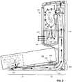
- Fig. 2shows a cut-away side view of a mobile robot and an evacuation station of the type shown in Fig. 1 .
- a mobile robot 200is docked at an evacuation station 205, thereby enabling the evacuation station 205 and the mobile robot 200 to communicate with one another (e.g., electronically and optically), as described herein.
- the evacuation station 205also depicted in Fig. 3 , includes a base 206 to receive the mobile robot 200 to enable the mobile robot 200 to dock at the evacuation station 205.
- the mobile robot 200may detect that its debris bin 210 is full, prompting the mobile robot 200 to dock at the evacuation station 205 so that the evacuation station 205 can evacuate the debris bin 210.
- the mobile robot 200may detect that it needs charging, also prompting the mobile robot 200 to return to the evacuation station 205 for charging.
- Both the mobile robot 200 and the evacuation station 205include electrical contacts.
- the electrical contacts 245are located along a rearward portion 246 of the base opposite to an intake port 227 located along a forward portion 247.
- the electrical contacts 240 on the mobile robot 200are located on a forward portion of the mobile robot 200.
- Electrical contacts 240 on the mobile robot 200mate to corresponding electrical contacts 245 on the base 206 when the mobile robot 200 is properly docked at the evacuation station 205.
- the mating between the electrical contacts 240 and the electrical contacts 245enables communication between the control system 208 on the evacuation station and a corresponding control system of the mobile robot 200.
- the evacuation station 205can initiate an evacuation operation and, in some cases, a charging operation, based on those communications.
- the communication between the mobile robot 200 and the evacuation station 205is provided over an infrared (IR) communication link.
- IRinfrared
- the electrical contacts 245 on the mobile robot 200are located on a back side of the mobile robot 200 rather than an underside of the mobile robot 200 and the corresponding electrical contacts 245 on the evacuation station 205 are positioned accordingly.
- the evacuation station 205can issue a command to the mobile robot 200 to initiate evacuation of the debris bin 210.
- the evacuation station 205sends a command to the mobile robot 200 and will only evacuate if the mobile robot 200 completes a proper handshake (e.g., electrical contact between the electric contacts 240 and the electrical contacts 245).
- the control system 208can send a communication to the mobile robot 200, and receive a response to this communication from the mobile robot 200 and, in response, initiate an evacuation operation of the debris bin 210.
- the control system 208can execute a charging operation to restore, wholly or partially, the power source of the mobile robot 200.
- the mobile robot 200can issue a command to the evacuation station 205 to initiate evacuation of the debris bin 210.
- the mobile robot 200can transmit the command to the evacuation station 205 through electrical signals, optical signals, or other appropriate signals.
- the mobile robot 200 and the evacuation station 205are aligned so that the evacuation station 205 can begin the evacuation operation.
- the intake port 227 of the evacuation station 205aligns with an exhaust port 225 of the debris bin 210. Alignment between the intake port 227 and the exhaust port 225 provides for continuity of a flow path 222, along which debris 215 travels between the debris bin 210 and a bag 235 in the evacuation station 205. As described herein, the debris 215 is suctioned by the evacuation station 205 from the debris bin 210 into the bag 235, where it is stored.
- the evacuation stationincludes a motor 218 connected to the canister 220.
- the motor 218is configured to draw air out of the canister 220, and through bag 235, which is air permeable. As a result, the motor 218 can create a negative air pressure within the canister 220.
- the motor 218responds to commands from the control system 208 to draw air out of the canister 220.
- the motor 218expels the air drawn out of the canister 220 through an exit port 223 on the canister 220.
- the removal of airgenerates negative air pressure in the canister 220, which evacuates the debris bin 210 by generating an air flow along the flow path 222 that suctions the debris 215.
- the debris 215moves along flow path 222 from the debris bin 210, through a door unit (not shown) on the debris bin 210, through the exhaust port 225 on the debris bin 210, through intake port 227 on the base 206, through multiple conduits 230a, 230b, 230c in the evacuation station 205, and into the bag 235.
- the bag 235can be an air permeable filter bag that can receive the debris 215 travelling along the flow path 222 - which can include flows of, for example, air and debris 215 - and separate the debris 215 from air.
- the bag 235can be disposable and formed of paper, fabric, or other appropriately porous material that allows air to pass through but traps the debris 215 within the bag 235.
- the evacuation station 205also includes a pressure sensor 228, which monitors the air pressure within the canister 220.
- the pressure sensor 228can include a Micro-Electro-Mechanical System (MEMS) pressure sensor or any other appropriate type of pressure sensor.
- MEMS pressure sensoris used in this implementation because of its ability to continue to accurately operate in the presence of vibrations due to, for example, mechanical motion of the motor 218 or motion from the environment transferred to the evacuation station 205.
- the pressure sensor 228can detect changes in air pressure in the canister 220 caused by the activation of the motor 218 to remove air from the canister 220. The length of time for which evacuation is performed may be based on the pressure measured by the pressure sensor 228, as described with respect to Fig. 4 .
- Fig. 4depicts an example graph 400 of air pressure 405 generated over a period of time 410 in response to the removal of air from canister 220.
- the air pressure 405, before activation by motor 218,can be atmospheric air pressure.
- the initial activation of the motor 218can cause an initial dip 415 in the air pressure 405.
- This initial dip 415can occur due to a cracking pressure needed to initially open a flap or door of the door unit on the debris bin. More particularly, the initial dip 415 can be associated with the flap including a biasing mechanism that requires a first air pressure to move initially from a closed position to an open position that is higher than a second air pressure to maintain the flap in the open position.
- fluctuations 420may occur in the air pressure 405 due to the movement of the debris 215 through the flow path 222. That is, the debris 215 can cause partial occlusions of the flow path 222 that can cause the air pressure 405 to experience the fluctuations 420.
- the partial occlusionscan cause the fluctuations 420 to include decreases in the air pressure 405.
- the air pressure 405can clear the partial occlusions and decrease resistance to the air flow. The fluctuations 420 may thus include increase in the air pressure 405 after the partial occlusions are cleared.
- steady state 425may include a constant pressure or fluctuations relative to a constant pressure that do not exceed a certain percentage, e.g., 1%, 2%, 3%, 4%, 5%, 6%, 7%, 8%, 9%, etc., over the course of a period of time.
- the control system 208can determine that the air pressure 405 has reached the steady state 425 by monitoring the air pressure 405 for a predefined period of time 430 following a start of evacuation.
- the air pressure 405can be detected by the pressure sensor 228 which, in turn, can generate and transmit air pressure signals to the control system 208 for the processing.
- the control system 208may use these pressure signals to determine when to terminate debris bin evacuation.
- itcan be advantageous to reduce the amount of evacuation time, since evacuation can be a relatively noisy process, and since evacuation time cuts-into cleaning time.
- the majority of debris 215is suctioned from the debris bin 210 within a fraction of the overall programmed evacuation time, making at least some of that time unnecessary.
- the programmed evacuation timeis 30 seconds, whereas the majority of debris is actually evacuated from the debris bin 210 within 5 seconds.
- the control system 208continues to control the motor 218 to cause the motor 218 to continue to apply the negative air pressure.
- This negative air pressureis applied for the predefined period of time 430, during which the air pressure 405 is maintained within a predefined range 435 (e.g., a range defined by a two-sided hysteresis).
- a predefined range 435e.g., a range defined by a two-sided hysteresis.
- the control system 208sends commands to stop operation of the motor 218, thereby terminating evacuation.
- the motor 218stops removing air from the canister 220, causing the air pressure 405 to return to atmospheric pressure.
- the predefined period of time 430can be, for example, 3 seconds, 4 seconds, 5 seconds, 6 seconds, 7 seconds, 8 seconds, 9 seconds, 10 seconds, 11 seconds, 12 seconds, 13 seconds, 14 seconds, 15 seconds, etc.
- the predefined range 435can be, for example, plus or minus 5 Pa, 10 Pa, 15 Pa, 20 Pa, etc.
- the predefined period of time 430 and the predefined rangecan be stored on a memory storage element operable with the control system 208.
- the steady state air pressure 405can decrease below a threshold pressure 440, which indicates that the bag 235 has become substantially full of debris.
- a threshold pressure 440indicates that the bag 235 has become substantially full of debris.
- a combination of a threshold pressure 440 and the trend of the steady state air pressure 405is used in some implementations.
- the steady state air pressure 405decreases as the bag 235 fills and it becomes more difficult to pull air through the bag 235.
- the threshold pressure 440can be pre-determined (e.g., stored in a memory storage element accessible by the control system 208) or it can be adjusted by the control system 208 based on a baseline reading of the steady state air pressure 405 when a new bag 235 is installed.
- the control system 208can determine, for example, when the steady state air pressure 405 is below the threshold pressure 440, the trend in the steady state air pressure 405 over multiple evacuations is sufficiently sloped, or any combination thereof, and can then transmit instructions for an operation in response to the air pressure 405 exceeding the threshold pressure 440.
- the control system 208can transmit commands to the motor 218 to end evacuation of the debris 215, thus causing the air pressure 405 to return to atmospheric pressure.
- the threshold pressure 440can between, for example, 600Pa to 950 Pa, but this will depend on conditions in the system and environment.
- the threshold pressure 440can indicate percent volume of the bag 235 occupied by the debris 215 between, for example 50% and 100%.
- the control system 208can also output instructions to a computer system, such as a server, which maintains a user account and which can notify the user that the bag is full and needs to be changed.
- the servercan output the information to an application ("app") on the user's mobile device, which the user can access to monitor their home system.
- a second threshold pressuree.g., a notification pressure
- a notification pressurecan be used to notify the user that the bag 235 is nearing the full state and a limited number of additional evacuations will be possible prior to replacement of the bag 235.
- the systemcan notify the user and allow the user to replace the bag 235 prior to the bag 235 being too full to allow evacuation of the robot bin.
- the control system 208can adaptively control an amount of evacuation time 445 that the control system 208 operates the motor 218 and, therefore, the amount of time that evacuation of the debris bin 210 occurs. For example, the point in time when the air pressure 405 exceeds the threshold pressure 440 and/or the point in time when the air pressure 405 is maintained within the predefined range 435 for the period of time 430 can dictate when evacuation ends. In some implementations, the control system 208 can control the evacuation time 445 to be between 15 seconds and 45 seconds.
- the air pressure 405, and thus the evacuation time 445can depend on a number of factors such as, but not limited to, an amount of debris stored in the debris bin 210 and flow characteristics caused by, e.g., the size, viscosity, water content, weight, etc. of the debris 215.
- Fig. 5shows a flow chart of an example process 500 in which a control system (e.g., the control system 208) operates a motor (e.g., the motor 218) of an evacuation station (e.g., the evacuation station 205) based on electrical contact signals and air pressure (e.g., the air pressure 405) in a canister (e.g., the canister 220) of the evacuation station.
- a control systeme.g., the control system 208 operates a motor (e.g., the motor 218) of an evacuation station (e.g., the evacuation station 205) based on electrical contact signals and air pressure (e.g., the air pressure 405) in a canister (e.g., the canister 220) of the evacuation station.
- a control systeme.g., the control system 208 operates a motor (e.g., the motor 218) of an evacuation station (e.g., the evacuation station 205) based on electrical contact signals and air pressure (e.g., the air pressure
- the control systemreceives (505) electrical contact signals.
- the electrical contact signalsindicate that a mobile robot is docked at the evacuation station.
- the electrical contact signalscan indicate that electrical contacts of a mobile robot are in electrical and physical contact with electrical contacts of the evacuation station.
- the control systemAfter receiving the electrical contact signals, the control system sends (507) optical start signals to initiate evacuation via, for example, an optical communication link.
- the mobile robottransmits the optical start signals using the optical communication link. Because the electrical contacts of the mobile robot are in contact with the electrical contacts of the evacuation station, the mobile robot is properly aligned with the evacuation station for the evacuation station to initiate the evacuation process by transmitting the optical start signals directly to the mobile robot. The mobile robot acknowledges the start optical signal with an acknowledgement optical signal to the evacuation station before the control system begins evacuation.
- the control systemthen transmits (510) commands to begin evacuation.
- the control systemcan transmit (510) the commands to begin evacuation after receiving the optical acknowledgement signal from the mobile robot to begin the evacuation.
- the evacuation stationdetects the received (505) electrical contact signals and transmits (510) commands to begin the evacuation after detecting the received (505) electrical contact signals.
- the evacuation stationthus does not receive optical start signals from the mobile robot to begin evacuation.
- the control systemdoes not receive (505) electrical contact signals when the electrical contacts mate.
- the controller of the mobile robotcan receive the electrical contact signals and then transmit the optical start signals to the control system in response to the electrical contact signals.
- the commands transmitted (510) by the control systemcan instruct the motor to activate as described herein. Specifically, the motor suctions air out of the canister of the evacuation station to generate a negative air pressure within the canister. The resulting negative air pressure extends along the flow path and into the robot's debris bin, causing suction of the debris from the robot's debris bin, through the flow path, and into an air permeable bag held in the canister.
- the control systemcontinues transmitting (515) the commands, thereby continuing operation of the motor and evacuation of debris.
- the control systemcan modify the power delivered to the motor to increase or decrease the amount of negative air pressure generated within the canister.
- the control systemcontinues to receive (520) air pressure signals from the pressure sensor in the canister while evacuation continues.
- the measured air pressure signalsvary due to variations in amounts of debris within the bag, blockage of the flow path, or the like.
- the control systemdetermines (525) whether the air pressure within the canister has reached steady state. To determine (525) whether the air pressure has reached steady state, the control system determines that it has received air pressure signals indicating a pressure within a defined range for at least predefined amount of time. If the control system determines that the air pressure has been in the steady state for the predefined amount of time, the control system can transmit (527) commands to end evacuation. If the control system determines (539) that the air pressure has not reached steady state air pressure, the control system can continue transmitting (515) commands for evacuation, receive (520) air pressure signals, and determine (525) whether to transmit (527) instructions to end evacuation. In other examples, the control system can have a pre-set evacuation time (length of evacuation). In such situations, the control system does not determine the completion of evacuation based on the pressure sensor signals.
- the systemdetermines (529) whether the steady state air pressure is (a) indicative of a non-full bag condition (b) in a range for notification of a bag that is reaching a full state, or (c) indicative of a bag full condition based on a comparison of the steady state air pressure to a threshold. If the control system determines that the air pressure exceeds both the notification and bag full threshold pressures, the control system awaits (530) the next evacuation process. If the control system determines (529) that the air pressure is below the notification threshold but above the bag full threshold pressure, the control system transmits (532) a notification to the user indicating that the bag is close to being full. If the control system determines (529) that the air pressure is below the bag full threshold pressure, the control system transmits (532) a notification to the user indicating that the bag is full and prohibits (534) further evacuation of the bin until the bag is replaced.
- motor 218generates negative air pressure in the canister 220 to create air flow along the flow path 222 to carry the debris 215 from the debris bin 210 to the bag 235 held in the canister 220.
- the control system 208uses air pressure monitored by the pressure sensor 228 to determine the evacuation time 445 that the control system 208 activates the motor 218 to evacuate the bag 235.
- sealing the air pressure of the canister 220 and the multiple conduits 230a, 230b, 230c from the environmentcan be advantageous so that the motor 218 operates more efficiently and so that the air pressure detected by the pressure sensor 228 can predictably inform the control system 208 of status of the evacuation operation.
- the intake port 227 of the evacuation station 205includes a rim 600 defining a perimeter of the intake port 227 and a seal 605 inside of the rim 600.
- the seal 605is disposed within the intake port 227, and is below the rim 600 (e.g., between 0.5 - 1.5 mm below the rim).
- the seal 605is not fixed relative to the intake port 227 or the rim 600, and is movable relative thereto, e.g., in response to negative air pressure experienced through the flow path.
- the rim 600can be located at a forward portion 247 of the evacuation station 205 so that, when the mobile robot 200 docks at the evacuation station 205, the intake port 227 aligns with the exhaust port 225 of the debris bin 210.
- the seal 605is protected from contact and frictional forces due to the mobile robot 200 docking at the evacuation station 205.
- the geometry of the rim 600 and the seal 605can reduce wear of the rim 600 and the seal 605 when the mobile robot 200 moves over the rim 600 to dock at the evacuation station 205.
- a height 700 of the rim 600is greater than a height 705 of the seal 605 such that, when the mobile robot 200 passes over the rim 600, the underside of the mobile robot 200 does not contact the seal 605.
- the height 705 of the seal 605is thus below an upper surface 707 of the rim 600.
- the height 700can also be less than a clearance 800 of an underside 805 of the mobile robot 200, as shown in Fig. 8 .
- the mobile robot 200can pass over the rim 600 when the mobile robot 200 docks at the evacuation station 205.
- the seal 605may be made of a deformable material that can be movable relative to the rim 600 in response to forces caused by, for example, the negative air pressure generated by the motor 218.
- the materialcan be, for example, a thin elastomer.
- the elastomer ethylene propylene diene monomer (EPDM) rubber, silicone rubber, polyether block amides, Chloropene rubber, Butyl rubber, among other elastomeric materialsIn the presence of the negative air pressure in the flow path during an evacuation operation, the seal 605 can respond to the negative air pressure generated during the evacuation operation by moving upward, toward the mobile robot 200, and deforming to form an air-tight seal with the mobile robot 200.
- the seal 605conforms to a shape of the mobile robot 200 in an area surrounding the exhaust port 225 of the debris bin 210.
- the seal 605has a width that is relative to the separation between the evacuation station 205 and the mobile robot 200 when the mobile robot 200 is located on the evacuation station 205 such that the seal 605 can extend upwardly to contact the underside 805 of the mobile robot 200 (e.g., 0.5 cm to 1.5 cm)
- the seal 605includes one or more slits 610 that allow the seal 605 to deform upward at corners of the seal 605 without generating excessive hoop stress in the seal 605 due to the upward deformation.
- the slit 610can thus increase a lifespan of the seal 605 and increase the number of or duration of evacuation operations executed by the evacuation station 205.
- the seal 605 and the rim 600cooperate to provide an air-tight seal between the debris bin 210 and the evacuation station 205 that is durable.
- the seal 605can be replaceable. A user can remove the seal 605 from the rim 600 and replace the seal 605.
- each of the conduits 230a, 230b, 230cin addition to providing a continuous flow path 222 for transporting debris, can include features that improve ease of operation, manipulation, and cleaning of the evacuation station 205.
- the conduit 230aextends partly along a bottom 900 of the base 206.
- the conduit 230aextends partly upward (e.g., along the z-axis) along the evacuation station 205, connecting the debris bin 210 to the conduit 230b.
- the conduit 230bextends upward from the conduit 230a, connecting the conduit 230a to the conduit 230c.
- Flexible grommets 905connect the conduit 230b to the conduit 230c.
- the conduit 230cextends upward from the conduit 230b and connects the conduit 230c to the bag 235.
- the conduit 230acan be sized, and dimensioned, such that a ramp 907, shown in Fig. 3 and described herein, can have a lower height along the forward portion 247.
- the conduit 230acan have a cross-sectional shape that transitions from at least partly rectangular to at least partly curved.
- a portion 1000a of the conduit 230a adjacent to the intake port 227can have a cross-sectional shape 1005a that is rectangular
- a portion 1000c of the conduit 230a adjacent to the canister 220can have a cross-sectional shape 1005c that is either circular or at least partly curved.
- the cross-sectional shape 1005cis partly circular.
- a portion 1000b of the conduit 230acan have a transitional cross-sectional shape 1005b that gradually transitions from the cross-sectional shape 1005a to the cross-sectional shape 1005c to reduce sharp geometries within the conduit 230a.
- the transitional cross-sectional shape 1005bcan be partly curved, partly rectangular, partly circular, or combinations thereof.
- the cross-sectional shape 1005acan have a smaller height than the cross-sectional shape 1005b and the cross-sectional shape 1005c so that the ramp 907 can have increasing height going from the forward portion 247 toward the rearward portion 246.
- the conduit 230acan include cross-sectional areas that remain constant between the intake port 227 and the conduit 230b to facilitate non-turbulent air flow through the flow path 222.
- the cross-sectional area of the cross-sectional shapes 1005a, 1005b, 1005ccan be substantially constant throughout the length of the conduit 230a to reduce influence of geometry on flow characteristics through the conduit 230a.
- the conduit 230acan be a transparent, removable conduit and/or a replaceable conduit in order to facilitate cleaning the debris 215 from the evacuation station 205.
- a usercan remove the conduit 230a and clean an interior of the conduit 230a to remove, for example, debris clogs trapped within the conduit 230a.
- the conduit 230acan be fastened to the base 206 using removable fasteners, such as, for example, screws, reversible snap fits, tongue and groove joints, and other fasteners. The user can remove the fasteners and then remove the conduit 230a from the base 206 to clean the interior of the conduit 230a.
- the conduits 230b, 230cincludes pipes that move relative to one another.
- the conduit 230bis a stationary pipe
- the conduit 230cis a movable pipe.
- a flexible grommet 905provides a flexible interface between the conduit 230b and the conduit 230c.
- the evacuation station 205can include one or more flexible grommets 905.
- the conduit 230cpivots at the interface between the conduit 230c and the conduit 230b because of the flexibility of the grommet 905.
- the conduit 230ccan be moved into position to interface with the bag 235 to establish the continuous flow path 222 between the debris bin 210 and the bag 235.
- the evacuation station 205can include a cam mechanism 1100 (shown in Figs. 12 and 13 ) and a plunger 1105 located within the canister 220.
- the cam mechanism 1100can include levers, cams, shuttles, and other components to transfer kinematic motion from the plunger 1105 to the conduit 230c.
- the plunger 1105can be an elongate component that moves axially (e.g., along the z-axis 1506Z of Fig. 3 ).
- the cam mechanism 1100controls movement of the conduit 230c based on movement of the plunger 1105 of the evacuation station 205.
- a top 1110 of the canister 220can be movable between an open position ( Fig. 12 ), and a closed position ( Fig. 13 ). Movement of the top 1110 from the open position to the closed position actuates the plunger 1105 which in turn causes the cam mechanism 1100 to move the conduit 230c relative to the conduit 230b. Moving the top 1110 from the open position ( Fig. 12 ) to the closed position ( Fig. 13 ) causes the conduit 230c to move from the receded position (circled in Fig.
- the conduit 230ccan be movable out of contact with the bag 235 in response to moving the top 1110 into the open position ( Fig. 12 ).
- the conduit 230ccan be movable into contact with the bag 235 in response to movement of the plunger 1105.
- the conduit 230ccan make a substantially airtight seal to a latex membrane 1305 of the bag 235.
- the conduit 230ccan create a path (e.g., the continuous flow path 222 through the conduits 230a, 230b, 230c) for the debris 215 and the air to pass between the debris bin 210 and the bag 235.
- the canistercan include alignment features, such as slots, that align the bag 235 with the bag interface end 1210 of the conduit 230c.
- the mechanisms of the top 1110 and the conduit 230cmay provide the user a convenient way to load the bag 235 in the evacuation station 205, and to remove the bag from the evacuation station.
- the userBefore the bag 235 is placed into the canister 220, the user can open the top 1110 ( Fig. 12 ), causing the conduit 230c to move into the receded position ( Fig. 12 ).
- the usercan then place the bag 235 into the canister 220 such that the bag 235 is aligned with the conduit 230c.
- the usercan close the top 1110 ( Fig. 13 ), causing the conduit 230c to move into the extended position ( Fig. 13 ).
- the bag interface end 1210 of the conduit 230ccan connect with the bag 235, thus interfacing the bag 235 with the conduit 230c.
- the usercan incorporate the bag 235 into the flow path 222 without significantly manually manipulating the bag 235 and the bag interface end 1210 of the conduit 230c.
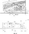
- the exhaust chamber 236includes a motor housing 1400 that houses the motor 218 (not shown in Fig. 14 ).
- the air exiting through the exit port 223carries energy associated with noise of the motor 218.
- the exhaust chamber 236can include features to reduce or decrease the amount of noise caused by the motor 218.
- the airtakes two split flow paths 1405a and 1405b out through the exit port 223.
- the split flow paths 1405a, 1405bexit through a portion 1407 of the motor housing 1400.
- the portion 1407faces away from the exit port 223 to extend the distance that air travels between the motor 218 and the exit port 223.
- the canister 220further includes foam insulation 1410 adjacent the split flow paths 1405a, 1405b that absorb sound as the air travels along the split flow paths 1405a, 1405b.
- the split flow path 1405a, 1405b and the foam insulation 1410can together reduce the noise caused by the motor 218.
- the evacuation station 205can include additional features that affect evacuation operation of the evacuation station 205.
- the ramp 907as shown in Fig. 3 and Fig. 15 , assists with guiding debris 215 towards the intake port 227.
- the ramp 907forms an angle 1502 with a surface 1505 on which the evacuation station 205 rests.
- the ramp 907increases in height relative to the surface 1505.
- the angle 1502allows gravity to cause debris 215 residing in the debris bin 210 to gather at toward the back of the debris bin 210 closer to the exhaust port 225 of the debris bin 210 when the mobile robot 200 docks at the evacuation station 205.
- gravityalso assists in moving the debris 215 toward the exhaust port 225 into the flow path 222.
- the angle of the ramp 907can expedite the evacuation operation.
- the evacuation station 205can include features to assist in proper alignment and positioning of the mobile robot 200 relative to the evacuation station 205.
- the ramp 907can include wheel ramps 1510 (shown in Fig. 3 ) that are sized and shaped appropriately to receive wheels of the mobile robot 200.
- the wheel ramps 1510can include traction features 1520 (shown in Fig. 3 ) that can increase traction between the mobile robot 200 and the ramp 907 so that the mobile robot 200 can navigate up the ramp 907 and dock at the evacuation station 205.
- the evacuation station 205can include, as shown in Fig. 15 , a robot stabilization protrusion 1525 on the mobile robot 200 that contacts a robot stabilization protrusion 1530 on the ramp 907.
- the robot stabilization protrusions 1525, 1530thus can maintain contact between the electrical contacts 240 of the mobile robot 200 with the electrical contacts 245 of the evacuation station 205.
- the robot stabilization protrusion 1530 on the ramp 907is located between a surface 1532 on the ramp 907 and the underside 805 of the mobile robot 200.
- the ramp 907can include two or more robot stabilization protrusions 1530 and/or two or more robot stabilization protrusions 1525.
- the negative air pressureresults in a force applied to a rear portion 1531 of the mobile robot 200.
- the forcecan cause motion of portions of the mobile robot 200 along the z-axis 1506Z.
- a frontward portion(not shown in Fig. 15 ) may lift off of the ramp 907, thus potentially resulting in misalignment between the electrical contacts 240 and the electrical contacts 245.
- Contact between the robot stabilization protrusion 1525 and the robot stabilization protrusion 1530can reduce motion of the mobile robot 200 caused by the force resulting from negative air pressure that can cause the mobile robot 200 to lift off of the ramp 907.
- the electrical contacts 240can remain in contact with the electrical contacts 245 so that the evacuation operation continues uninterrupted.
- the evacuation stations(e.g., the evacuation station 205) described herein can be used with a number of types of mobile robots that include bins to store debris.
- the evacuation stationscan evacuate the debris from the bins.
- a mobile robot 1600can be a robotic vacuum cleaner that ingests debris from a floor surface.
- the mobile robot 1600includes a body 1602 that navigates about a floor surface 1603 using drive wheels 1604.
- a caster wheel 1605 and the drive wheels 1604support the body 1602 over the floor surface 1603.
- the drive wheels 1604 and the caster wheel 1605can support the body 1602, and hence a debris bin 1612 (e.g., the debris bin 210), such that the debris bin 1612 is supported a clearance distance 1611 between 3 and 15 mm above the surface 1603.
- the mobile robot 1600ingests debris 1610 (e.g., the debris 215) using a suction mechanism 1606 to generate an airflow 1608 that causes the debris 1610 on the floor surface 1603 to be propelled into the debris bin 1612.
- the suction mechanism 1606can thus suction debris 1610 from the floor surface 1603 into the debris bin 1612 during traversal of the floor surface 1603.
- the body 1602supports a front roller 1614a and a rear roller 1614b that cooperate to retrieve debris 1610 from the surface 1603. More particularly, the rear roller 1614b rotates in a counterclockwise sense CC, and the front roller 1614a rotates in a clockwise sense C.
- the debris bin 1612includes a chamber 1613 to hold the debris 1610 received by the mobile robot 1600.
- a control system 1615(implemented, e.g., by one or more processing devices) can control operation of the mobile robot 1600 as the mobile robot 1600 traverses the floor surface 1603. For example, during a cleaning operation, the control system 1615 can cause motors (not shown) to rotate the drive wheels 1604 to cause the mobile robot 1600 to move across the floor surface 1603. The control system 1615, during the cleaning operation, can further activate motors to cause rotation of the front roller 1614a and the rear roller 1614b and to activate the suction mechanism 1606 to retrieve the debris 1610 from the floor surface 1603.
- the debris bin 1612provides an interface between the chamber 1613 and an evacuation station (e.g., the evacuation station 205) such that the evacuation station can evacuate the debris 1610 stored in the chamber 1613 and the debris bin 1612.
- the debris bin 1612includes an exhaust port 1616 (e.g., the exhaust port 225) through which debris 1610 can exit the chamber 1613 of the debris bin 1612 into the evacuation station.
- a bin door 1701is open so that an evacuation door unit 1700 is visible. During the cleaning operation and the evacuation operation, the bin door 1701 is typically closed. The user can open the bin door 1701 by rotating the bin door 1701 about hinges 1706 to manually empty debris 1610 from the debris bin 1612.
- the evacuation door unit 1700 of the debris bin 1612can include a flap (also referred to as a door) 1705 that opens and closes to control flow of the debris 1610 between the chamber 1613 and external devices.
- the door unit 1700includes a support structure 1702 disposed within the debris bin 1612.
- the support structure 1702can be semi-spherical.
- the door unit 1700is located over the exhaust port 1616.
- the flap 1705is configured to move between a closed position shown in Fig. 17 and an open position shown in Fig. 18 .
- the flap 1705is mounted on the support structure 1702. The flap 1705 moves from the closed position to the open position in response to a difference in air pressure at the exhaust port and within the debris bin 1612.
- the evacuation stationcan generate a negative air pressure, thus causing the air in the debris bin 1612 to generate an air pressure that moves the flap 1705 from the closed position ( Fig. 17 ) to the open position ( Fig. 18 ).
- the flap 1705blocks airflow between the debris bin 1612 and the environment.
- the flap 1705provides a path 1800 between the debris bin 1612 and the exhaust port 1616.
- the door unit 1700can include a biasing mechanism that biases the flap 1705 into the closed position ( Fig. 17 ).
- a torsion spring 1900biases the flap 1705 into the closed position ( Fig. 17 ).
- the flap 1705rotates about a hinge 1902 having a rotational axis 1905, and the torsion spring 1900 applies force that generates a torque about the axis 1905 that biases the flap 1705 into the closed position ( Fig. 17 ).
- the hinge 1902connects the flap 1705 to the support structure 1702 of the door unit 1700.
- a leaf spring 1910biases the flap 1705 into the closed position.
- the flap 1705rotates about a flexible coupler 1912 that has an approximate rotational axis, and the leaf spring 1910 applies force that generates a torque about the rotational axis that biases the flap into the closed position.
- the flexible coupler 1912acts like a hinge which does not have any relative rotation of parts at a mechanical interface, like a mechanical hinge.
- Fig. 19C and 19Ddepicts a cross-sectional view of the door unit 1700 and a relaxing spring 1920 of the door unit 1700 that biases the flap 1705 into the closed position.
- the spring force that holds the flap 1705 shutrelaxes as the flap 1705 opens.
- the magnitude of the pressure wave that the debris bin sees during evacuationis determined by the cracking pressure on the flap 1705.
- the amount of material evacuatedis affected by how wide the flap 1705 opens. With flow, after the flap 1705 opens, the pressure drops.
- the relaxing spring 1920is believed to provide a spring with a high crack force but a low dwell force.
- the flap 1705is designed to be closed by a sliding interaction between the spring 1920 and a lever arm 1925 as the flap 1705 opens, the contact point slides up and shortens the lever arm 1925 between the spring 1920 and a flap pivot 1930 and thus reduces the moment on the flap 1705. As a result, a smaller force on the flap 1705 (e.g., from pressure) is required to maintain the flap 1705 open. In some examples, the sliding could be aided by a roller on the flap 1705 along the lever arm 1925 to reduce sliding friction.
- the air pressure generated against the flap 1705causes the flap 1705 to overcome the biasing force exerted by the biasing mechanism (e.g., the torsion spring 1900, the leaf spring 1910, the relaxing spring 1920), thus causing the flap 1705 to move from the closed position ( Fig. 17 ) to the open position ( Fig. 18 ).
- the biasing mechanisme.g., the torsion spring 1900, the leaf spring 1910, the relaxing spring 1920
- the flap 1705 of the door unit 1700closes the exhaust port 1616 such that the debris 1610 cannot escape through the exhaust port 1616.
- the debris 1610 ingested into the debris bin 1612remains in the chamber 1613.
- air pressurecauses the flap 1705 of the door unit 1700 to open, thereby exposing the exhaust port 1616 such that the debris 1610 in the chamber 1613 can exit through the exhaust port 1616 into the evacuation station.
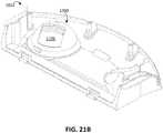
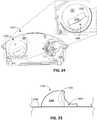
- Figs. 20 to 22depict the flap 1705 in the closed position.
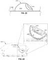
- Figs. 23 , 24, and 25show the same perspectives of the door unit 1700, as Figs. 20, 21A , and 22 , respectively, but the flap 1705 is in the open position.
- a biasing mechanism 2030e.g., a biasing mechanism that includes the torsion spring 1900 of Fig. 19A , the leaf spring 1910 of Fig. 19B , or the relaxing spring 1920 of Figs. 19C and 19D ), biases the flap 1705 into the closed position ( Figs. 20 to 22 ).
- the negative air pressurecauses the flap 1705 to move into the open position ( Figs. 23 to 25 ).
- the flap 1705 in the open position ( Figs. 23 to 25 )forms the path 1800, which allows air and thus the debris 1610 to flow through the exhaust port 1616 into the evacuation station.
- the flap 1705 in the closed position in Fig. 22 and in the open position in Fig. 25remain within an exterior surface 2200 (e.g., a bottom surface) of the debris bin 1610, Thus, the flap 1705 cannot inadvertently contact objects outside of the debris bin 1610, such as the floor surface 1603 about which the mobile robot 1600 moves.
- the flap 1705at a full extension toward the exterior surface 2200 when the flap 1705 is in the open position ( Fig. 25 ), the flap 1705 is above the exterior surface 2200 by a distance between 0 and 10 mm.
- the biasing mechanism 2030(e.g., which can include the torsion spring 1900, the leaf spring 1910, or the relaxing spring 1920) can have a nonlinear response to the air pressure at the exhaust port 1616. For example, as the flap 1705 moves from the closed position to the open position, the torque generated by the biasing mechanism 2030 can decrease because a lever arm about the axis 1905 for the biasing force of the biasing mechanism 2030 decreases.
- the biasing mechanism 2030can require a first air pressure to move initially from the closed position ( Figs. 20 to 22 ) to the open position ( Figs. 23 to 25 ) that is higher than a second air pressure to maintain the door in the open position ( Figs. 23 to 25 ).
- the first air pressurecan be 0% to 100% greater than the second air pressure, depending on conditions in the environment and the composition of the debris.
- the door unit 1700can be positioned to increase the speed at which debris 1610 can be evacuated from the debris bin 1612.
- Fig. 20which shows the flap 1705 in the closed position (e.g., as shown in Fig. 17 )
- the door unit 1700is located on a half 2000 of a full length 2002 of the debris bin 1612.
- the door unit 1700is located opposite to the suctioning mechanism 1606 that occupies a half 2005 of the full length 2002.
- the door unit 1700is located adjacent a corner 2010 of the debris bin 1612 such that the door unit 1700 is within a distance of 0% to 25% of the full length 2002 of the debris bin 1612 to the corner 2010.
- the door unit 1700can be partially located within a rearward portion 2007 of the debris bin 1612.
- the flap 1705faces outwardly towards the debris bin 1612 from the corner 2010 such that debris 1610 from a large portion of the debris bin 1612 is directed toward the path 1800 provided by the flap 1705 in the open position ( Figs. 23 to 25 ).
- the negative air pressurecan cause debris 1610 from difficult-to-reach locations throughout the debris bin 1612-including, for example, corners and areas in the rearward portion 2007-to flow into the path 1800 to be evacuated into the evacuation station.
- the full length 2002 of the debris bin 1612is between 20 and 50 centimeters.
- the debris bincan have a width 2015 between 10 and 20 centimeters.
- the door unit 1700is located between 0 to 8 centimeters from the corner 2010 (e.g., a horizontal distance between 0 and 8 centimeters, a vertical distance between 0 and 8 centimeters).
- the door unit 1700can have a diameter between 2 centimeters and 6 centimeters.
- the flap 1705can be made of a solid plastic or other rigid material and can be concavely curved relative to, the support structure 1702.
- air pressure within the debris bin 1612 on the flap 1705 during the evacuation operationcan result in greater forces on the flap 1705 to cause the flap 1705 to more easily move from the open position ( Figs. 20 to 22 ) to the closed position ( Figs. 23 to 25 ).
- a stretchable material 2100can cover part of the flap 1705 such that debris 1610 entering through the path 1800 when the flap 1705 is open ( Figs. 23 to 25 ) does become lodged between the flap 1705 and the support structure 1702.
- the stretchable material 2100can be formed of a resilient material, such as an elastomer.
- the stretchable material 2100can be formed of ethylene propylene diene monomer (EPDM) rubber, silicone rubber, polyether block amides, Chloropene rubber, Butyl rubber, among other elastomeric materials.
- EPDMethylene propylene diene monomer
- silicone rubbersilicone rubber
- polyether block amidessuch as silicone rubber
- Chloropene rubberChloropene rubber
- Butyl rubberamong other elastomeric materials.
- the stretchable material 2100can cover an intersection 2105 (shown in Fig. 21A ) of the flap 1705 and the support structure 1702.
- Debris 1610 and other foreign material along the intersection 2105can prevent the flap 1705 from closing and forming a seal with the support structure 1702.
- the stretchable material 2100prevents debris 1610 from gathering at the intersection 2105 so that the debris 1610 does not interfere with proper functionality of the flap 1705 of the door unit 1700.
- the hinge and stretchable materialcould be replaced with a flexible coupler (e.g., as described with respect to Fig. 19B ) made of similar stretchable materials to perform the same function.
- the flap 1705is attached to the support structure 1702 by the flexible coupler.
- An adhesivecan be used to adhere the stretchable material 2100 to the flap 1705 and to the support structure 1702.
- the stretchable material 2100can be adhered to the flap 1705 along a fixed portion 2110 and can be adhered to the support structure 1702 along a fixed portion 2120.
- the adhesivecan be absent at a location 2130 of or above the hinge (e.g., the hinge 1902) about which the flap 1705.
- the adhesivecan further be absent at the intersection 2105 of the flap 1705 and the support structure 1702.
- the stretchable material 2100can flex and deform along the location 2130 while the fixed portions 2110, 2120 of the stretchable material 2100 remain fixed to the flap 1705 and the support structure 1702, respectively, and do not flex.
- the absence of adhesive along the location 2130provides a flexible portion for the stretchable material 2100 so that the stretchable material 2100 does not break or fracture due to excessive stress caused by the movement of the flap 1705 from the closed position ( Figs. 20 to 22 ) to the open position ( Figs. 23 to 25 ).
- the flap 1705biased into the closed position ( Figs. 20 to 22 ) due to the biasing mechanism 2030 prevents the debris 1610 from exiting the debris bin 1612 through the exhaust port 1616.
- the mobile robot 200docks at the evacuation station so that the evacuation station can generate negative air pressure to evacuate the debris 1610.
- the debris 1610can flow through the exhaust port 1616 with air flow generated during the evacuation operation.
- the flap 1705forced into the open position ( Figs. 23 to 25 ) due to the negative air pressure generated during the evacuation operation, provides the path 1800 so that the debris 1610 can travel along a flow path (e.g., flow path 222) to a bag (e.g., bag 235) of the evacuation station.
- a flow pathe.g., flow path 222
- a bage.g., bag 235
- the stretchable material 2100further prevents the debris 1610 from gathering around the biasing mechanism 2030 and at the intersection 2105.
- the biasing mechanism 2030can easily bias the flap 1705 into the closed position ( Figs. 20 to 22 ), and the mobile robot 200 can continue the cleaning operation and continue ingesting debris 1610 and storing debris 1610 in the debris bin 1612.
- the robots described hereincan be controlled, at least in part, using one or more computer program products, e.g., one or more computer programs tangibly embodied in one or more information carriers, such as one or more non-transitory machine-readable media, for execution by, or to control the operation of, one or more data processing apparatus, e.g., a programmable processor, a computer, multiple computers, and/or programmable logic components.
- one or more computer program productse.g., one or more computer programs tangibly embodied in one or more information carriers, such as one or more non-transitory machine-readable media, for execution by, or to control the operation of, one or more data processing apparatus, e.g., a programmable processor, a computer, multiple computers, and/or programmable logic components.
- a computer programcan be written in any form of programming language, including compiled or interpreted languages, and it can be deployed in any form, including as a stand-alone program or as a module, component, subroutine, or other unit suitable for use in a computing environment.
- Operations associated with controlling the robots described hereincan be performed by one or more programmable processors executing one or more computer programs to perform the functions described herein. Control over all or part of the robots and evacuation stations described herein can be implemented using special purpose logic circuitry, e.g., an FPGA (field programmable gate array) and/or an ASIC (application-specific integrated circuit).
- special purpose logic circuitrye.g., an FPGA (field programmable gate array) and/or an ASIC (application-specific integrated circuit).
- processors suitable for the execution of a computer programinclude, by way of example, both general and special purpose microprocessors, and any one or more processors of any kind of digital computer.
- a processorwill receive instructions and data from a read-only storage area or a random access storage area or both.
- Elements of a computerinclude one or more processors for executing instructions and one or more storage area devices for storing instructions and data.
- a computerwill also include, or be operatively coupled to receive data from, or transfer data to, or both, one or more machine-readable storage media, such as mass PCBs for storing data, e.g., magnetic, magneto-optical disks, or optical disks.
- Machine-readable storage media suitable for embodying computer program instructions and datainclude all forms of non-volatile storage area, including by way of example, semiconductor storage area devices, e.g., EPROM, EEPROM, and flash storage area devices; magnetic disks, e.g., internal hard disks or removable disks; magneto-optical disks; and CD-ROM and DVD-ROM disks.
- semiconductor storage area devicese.g., EPROM, EEPROM, and flash storage area devices
- magnetic diskse.g., internal hard disks or removable disks
- magneto-optical diskse.g., CD-ROM and DVD-ROM disks.
Landscapes
- Engineering & Computer Science (AREA)
- Mechanical Engineering (AREA)
- Electric Vacuum Cleaner (AREA)
- Manipulator (AREA)
- Filters For Electric Vacuum Cleaners (AREA)
- Electric Suction Cleaners (AREA)
- Cleaning In General (AREA)
Description
- This specification relates generally to evacuating debris collected by a mobile robot.
- Cleaning robots include mobile robots that perform desired cleaning tasks, such as vacuuming, in unstructured environments. Many kinds of cleaning robots are autonomous to some degree and in different ways. For example, an autonomous cleaning robot may be designed to automatically dock with an evacuation station for the purpose of emptying its cleaning bin of vacuumed debris.
WO 2015/082019 A1 discloses a self-propelled and self-steering floor cleaning device which comprises at least one cleaning aggregate and a dirt collecting container which has a container interior, a bottom, a dirt inlet opening, and a dirt outlet opening, wherein dirt particles can be transferred by means of the at least one clearing aggregate into the container interior and the dirt outlet opening is formed on the bottom. In order to provide a floor cleaning device of this type, which enables a simple removal of dirt particles from the dirt collecting container while achieving a simple construction, it is proposed according to the invention that the floor cleaning device has a valve device arranged on the dirt outlet opening comprising at least one valve body which, in a closed position, forms the bottom at least in sections and closes the dirt outlet opening, and which can transfer into an open position, in which the dirt outlet opening is at least partially released, and that the valve device can be activated by air pressure for transferring the at least one valve body from the closed position into the open position. - In some examples, a mobile robot includes a body configured to traverse a surface and to receive debris from the surface, and a debris bin within the body. The debris bin includes a chamber to hold the debris received by the mobile robot, an exhaust port through which the debris exits the debris bin; and a door unit over the exhaust port. The door unit includes a flap configured to move, in response to air pressure at the exhaust port, between a closed position to cover the exhaust port and an open position to open a path between the chamber and the exhaust port.
- The door unit, including the flap in the open position and in the closed position, is within an exterior surface of the mobile robot.
- In some examples, the door unit can include a semi-spherical support structure within the debris bin. The flap can be mounted on, and concavely curved relative to, the semi-spherical support structure.
- The exhaust port and the door unit can be adjacent to a corner of the debris bin and can be positioned so that the flap faces outwardly towards the debris bin relative to the corner.
- The flap can be connected to the semi-spherical support structure by one or more hinges. The door unit can further include a stretchable material adhered, by an adhesive, to both the flap and the semi-spherical support structure. The stretchable material can cover the one or more hinges and an intersection of the flap and the semi-spherical support structure. The adhesive can be absent at a location of the one or more hinges and at the intersection of the flap and the semi-spherical support structure.
- The flap can be connected to the semi-spherical support structure by a biasing mechanism. In some examples, the biasing mechanism can include a torsion spring. The torsion spring can be connected to both the flap and the semi-spherical support structure. The torsion spring can have a nonlinear response to the air pressure at the exhaust port. The torsion spring can require a first air pressure to move and thereby place the flap in an open position and a second air pressure to maintain the flap in the open position. The first air pressure can be greater than the second air pressure.
- In some examples, the biasing mechanism can include a relaxing spring that can require a first air pressure to move and thereby place the flap in an open position and a second air pressure to maintain the flap in the open position. The first air pressure can be greater than the second air pressure.
- In some examples, the mobile robot can be a vacuum cleaner including a suction mechanism. The surface can be a floor. The mobile robot can further include a controller to control operation of the mobile robot to traverse the floor. The controller can control the suction mechanism for suctioning debris from the floor into the debris bin during traversal of the floor.
- In some examples, an evacuation station includes a control system including one or more processing devices programmed to control evacuation of a debris bin of a mobile robot. The evacuation station includes a base to receive the mobile robot. The base includes an intake port to align to an exhaust port of the debris bin. The evacuation station further includes a canister to hold a bag to store debris from the debris bin and one or more conduits extending from the intake port to the bag through which debris is transported between the intake port and the bag. The evacuation station also includes a motor that is responsive to commands from the control system to remove air from the canister and thereby generate negative air pressure in the canister to evacuate the debris bin by suctioning the debris from the debris bin, and a pressure sensor to monitor the air pressure. The control system is programmed to control an amount of time to evacuate the debris bin based on the air pressure monitored by the pressure sensor.
- In some examples, to control the amount of time to evacuate the debris bin based on the air pressure, the control system can be programmed to detect a steady state air pressure following a start of evacuation. The control system can be programmed to continue to apply the negative pressure for a predefined period of time during which the steady state air pressure is maintained and to send a command to stop operation of the motor.
- The base can include electrical contacts that can mate to corresponding electrical contacts on the mobile robot to enable communication between the control system and the mobile robot. The control system can be programmed to receive a command from the mobile robot to initiate evacuation of the debris bin.
- In some examples, the pressure sensor can include a Micro-Electro-Mechanical System (MEMS) pressure sensor.
- In some examples, the intake port can include a rim that defines a perimeter of the intake port. The rim can have a height that is less than a clearance of an underside of the mobile robot, thereby allowing the mobile robot to pass over the rim. The intake port can include a seal inside of the rim. The seal can include a deformable material that is movable relative to the rim in response to the air pressure. In some examples, in response to the air pressure, the seal can be movable to contact, and conform to, a shape of the exhaust port of the debris bin. The seal can include one or more slits therein. In some examples, the seal can have a height that is less than a height of the rim and, absent the air pressure, is below an upper surface of the rim.
- In some examples, the one or more conduits can include a removable conduit extending at least partly along a bottom of the base between the intake port and the canister. The removable conduit can have a cross-sectional shape that transitions from at least partly rectangular adjacent to the intake port to at least partly curved adjacent to the canister. The cross-sectional shape of the removable conduit can be at least partly circular adjacent to the canister.
- In some examples, the evacuation station can further include foam insulation within the canister. The motor can be arranged to draw air from the canister along split paths adjacent to the foam insulation leading to an exit port on the canister.
- In some examples, the base can include a ramp that increases in height relative to a surface on which the evacuation station rests. The ramp can include one or more robot stabilization protrusions between a surface of the ramp and an underside of the mobile robot.
- In some examples, the canister can include a top that is movable between an open position and a closed position. The top can include a plunger that is actuated as the top is closed. The one or more conduits can include a first pipe and a second pipe within the canister. The first pipe can be stationary, and the second pipe can be movable into contact with the bag in response to movement of the plunger, thereby creating a path for debris to pass between the debris bin and the bag. The second pipe, when in contact with the bag, can make a substantially airtight seal to a latex membrane of the bag. The first pipe and the second pipe can be interfaced via flexible grommets. A cam mechanism can control movement of the second pipe based on movement of the plunger. The second pipe can be movable out of contact with the bag in response to moving the top into the open position.
- In some examples, the control system can be programmed to control the amount of time to evacuate the debris bin based on the air pressure exceeding a threshold pressure of the canister. The threshold pressure can indicate that the bag has become full of the debris.
- Advantages of the foregoing may include, but are not limited to, the following. The flap (also referred to as the door), by remaining enclosed within the exterior surface of the robot, will not contact objects in the environment when the flap (door) is in the open position. As a result, in some examples, if the flap is opened when the robot navigates along a floor surface, the flap does not contact the floor surface. The flap can be made of a flexible or compliant material or can be made of a rigid material such as a plastic.
- The deformable material can last through several evacuation operations before being replaced. By being below the rim, the deformable material does not contact the mobile robot while the mobile robot is docking at the evacuation station and thus does not experience friction and contact forces that can damage the deformable material. Because the material is deformable, the material can improve air flow by creating an air-tight seal between the exhaust port of the debris bin and the intake port of the evacuation station. The seal can prevent air from leaking between the exhaust port and the intake port and can thus improve the efficiency of the negative air pressure used during the evacuation operation.
- The removable conduit allows the user to easily clean debris stuck or entrained within the removable conduit. The cross-sectional shapes of the removable conduit allow the removable conduit to transport air (and, hence, the debris) without causing significant turbulence. The cross-sectional shapes of the removable conduit, by transitioning from a rectangular shape to a curved shape, further allow the base of the evacuation station to be angled to include a ramp having increasing height, which improves efficiency of evacuating debris from the debris bin.
- The movable conduit allows the user to place a bag into the evacuation station without requiring the user to directly manipulate the bag to allow flow of air and debris to pass through the movable pipe into the bag. Rather, the user can simply place the bag in a canister of the evacuation station and close the top. The bag thus requires less user manipulation to operate with the evacuation station.
- The controller can adaptively control the time in which it performs the evacuation operation (e.g., operates a motor of the evacuation station). The time of the evacuation operation can thus be minimized to improve power efficiency of the evacuation station and to reduce the time that the evacuation operation generates noise in the environment (caused by, for example, the motor of the evacuation station).
- Any two or more of the features described in this specification, including in this summary section, can be combined to form implementations not specifically described herein.
- The robots, or operational aspects thereof, described herein can be implemented as/controlled by a computer program product that includes instructions that are stored on one or more non-transitory machine-readable storage media, and that are executable on one or more processing devices to control (e.g., to coordinate) the operations described herein. The robots, or operational aspects thereof, described herein can be implemented as part of a system or method that can include one or more processing devices and memory to store executable instructions to implement various operations.
- The details of one or more implementations are set forth in the accompanying drawings and the description below. Other features and advantages will be apparent from the description and drawings, and from the claims.
Fig. 1 is a perspective view of a mobile robot navigating in an environment with an evacuation station.Fig. 2 is cross-sectional side view of an evacuation station and a mobile robot docked at the evacuation station.Fig. 3 is a top perspective view of the evacuation station ofFig. 2 .Fig. 4 is a graph of air pressure monitored over a period of time in a canister of the evacuation station ofFig. 2 .Fig. 5 is a flow chart of a process to operate an evacuation station.Fig. 6 is a top view of a seal of the evacuation station ofFig. 2 .Fig. 7 is a cross-sectional side view of the seal ofFig. 6 .Fig. 8 is a cross-sectional side view of the seal ofFig. 7 with the mobile robot docked at the evacuation station ofFig. 2 .Fig. 9 is a cross-sectional side view of the evacuation station ofFig. 2 .Fig. 10 is a bottom view of a base of the evacuation station ofFig. 2 .Fig. 11 is a top perspective view of a canister of the evacuation station ofFig. 2 .Fig. 12 is a cross-sectional side view of the canister ofFig. 11 with a top of the canister in an open position.Fig. 13 is a cross-sectional side view of the canister ofFig. 11 with the top ofFig. 12 in a closed position.Fig. 14 is a cross-sectional top view of an exhaust chamber of the evacuation station ofFig. 2 .Fig. 15 is a cross-sectional side view of a ramp of the evacuation chamber ofFig. 2 .Fig. 16 is a schematic side view of an example mobile robot.Fig. 17 is a front view of a debris bin for the mobile robot ofFig. 16 with a bin door in an open position.Fig. 18 is a front view of the debris bin ofFig. 17 with the bin door in a closed position.Fig. 19A is a bottom perspective view of a door unit for a debris bin.Fig. 19B is a bottom perspective view of another door unit for a debris bin.Figs. 19C and 19D are views of yet another door unit for a debris bin.Fig. 20 is a bottom view of the debris bin ofFig. 17 .Fig. 21A is a top cross-sectional view of the debris bin ofFig. 17 .Fig. 21B is a top perspective cross-sectional view of the debris bin ofFig. 17 .Fig. 22 is a schematic side view of a door unit of the debris bin ofFig. 17 .Fig. 23 is a bottom view of the debris bin ofFig. 18 .Fig. 24 is a top cross-sectional view of the debris bin ofFig. 18 .Fig. 25 is a schematic side view of a door unit of the debris bin ofFig. 18 .- Like reference numerals in different figures indicate like elements.
- Described herein are example robots configured to traverse (or to navigate) surfaces, such as floors, carpets, or other materials, and to perform various cleaning operations including, but not limited to, vacuuming. Also described herein are examples of evacuation stations, at which the mobile robots can dock to evacuate debris stored in debris bins on the mobile robots. Referring to the example of
Fig. 1 , amobile robot 100 is configured to execute a cleaning operation to ingest debris as the mobile robot navigates about a surface 105 of an environment 110. The ingested debris is stored in adebris bin 115 on themobile robot 100. Thedebris bin 115 becomes full after themobile robot 100 has ingested a certain amount of debris. - After the debris bin has become full, the mobile robot can navigate to and dock at an
evacuation station 120. Generally, an evacuation station can additionally serve as, for example, a charging station and a docking station. The evacuation station includes a base station configured to remove debris from the debris bin, and to perform other functions vis-à-vis the mobile robot, such as charging. The evacuation station includes a control system, which can include one or more processing devices that are programmed to control operation of the evacuation station. In this example, theevacuation station 120 is controlled to generate negative air pressure to suction ingested debris out of thedebris bin 115 and into theevacuation station 120. As part of the evacuation operation, the debris is directed into a removable bag (not shown inFig. 1 ) housed in a canister 125 in theevacuation station 120. Between thedebris bin 115 and the bag, theevacuation station 120 includes conduits (not shown inFig. 1 ) that allow debris to pass from thedebris bin 115 and into the bag. As described herein, the conduits can include a removable conduit that can be removed and cleaned, and a movable conduit that is controllable to move into, and out of, contact with the bag. Following evacuation, themobile robot 100 can undock from theevacuation station 120, and execute a new cleaning (or other) operation. Theevacuation station 120 also includes one or more ports, to which themobile robot 100 interfaces for charging. Fig. 2 shows a cut-away side view of a mobile robot and an evacuation station of the type shown inFig. 1 . InFig. 2 , amobile robot 200 is docked at anevacuation station 205, thereby enabling theevacuation station 205 and themobile robot 200 to communicate with one another (e.g., electronically and optically), as described herein. Theevacuation station 205, also depicted inFig. 3 , includes a base 206 to receive themobile robot 200 to enable themobile robot 200 to dock at theevacuation station 205. Themobile robot 200 may detect that itsdebris bin 210 is full, prompting themobile robot 200 to dock at theevacuation station 205 so that theevacuation station 205 can evacuate thedebris bin 210. Themobile robot 200 may detect that it needs charging, also prompting themobile robot 200 to return to theevacuation station 205 for charging.- Both the
mobile robot 200 and theevacuation station 205 include electrical contacts. On theevacuation station 205, theelectrical contacts 245 are located along arearward portion 246 of the base opposite to anintake port 227 located along aforward portion 247. Theelectrical contacts 240 on themobile robot 200 are located on a forward portion of themobile robot 200.Electrical contacts 240 on themobile robot 200 mate to correspondingelectrical contacts 245 on the base 206 when themobile robot 200 is properly docked at theevacuation station 205. The mating between theelectrical contacts 240 and theelectrical contacts 245 enables communication between thecontrol system 208 on the evacuation station and a corresponding control system of themobile robot 200. Theevacuation station 205 can initiate an evacuation operation and, in some cases, a charging operation, based on those communications. In other examples, the communication between themobile robot 200 and theevacuation station 205 is provided over an infrared (IR) communication link. In some examples, theelectrical contacts 245 on themobile robot 200 are located on a back side of themobile robot 200 rather than an underside of themobile robot 200 and the correspondingelectrical contacts 245 on theevacuation station 205 are positioned accordingly. - For example, when the
electrical contacts evacuation station 205 can issue a command to themobile robot 200 to initiate evacuation of thedebris bin 210. In some examples, theevacuation station 205 sends a command to themobile robot 200 and will only evacuate if themobile robot 200 completes a proper handshake (e.g., electrical contact between theelectric contacts 240 and the electrical contacts 245). For example, thecontrol system 208 can send a communication to themobile robot 200, and receive a response to this communication from themobile robot 200 and, in response, initiate an evacuation operation of thedebris bin 210. Additionally or alternatively, when theelectrical contacts control system 208 can execute a charging operation to restore, wholly or partially, the power source of themobile robot 200. In other examples, when theelectrical contacts mobile robot 200 can issue a command to theevacuation station 205 to initiate evacuation of thedebris bin 210. Themobile robot 200 can transmit the command to theevacuation station 205 through electrical signals, optical signals, or other appropriate signals. - Also, when the
electrical contacts mobile robot 200 and theevacuation station 205 are aligned so that theevacuation station 205 can begin the evacuation operation. For example, theintake port 227 of theevacuation station 205 aligns with anexhaust port 225 of thedebris bin 210. Alignment between theintake port 227 and theexhaust port 225 provides for continuity of aflow path 222, along whichdebris 215 travels between thedebris bin 210 and abag 235 in theevacuation station 205. As described herein, thedebris 215 is suctioned by theevacuation station 205 from thedebris bin 210 into thebag 235, where it is stored. - In this regard, the evacuation station includes a
motor 218 connected to thecanister 220. Themotor 218 is configured to draw air out of thecanister 220, and throughbag 235, which is air permeable. As a result, themotor 218 can create a negative air pressure within thecanister 220. Themotor 218 responds to commands from thecontrol system 208 to draw air out of thecanister 220. Themotor 218 expels the air drawn out of thecanister 220 through anexit port 223 on thecanister 220. As noted, the removal of air generates negative air pressure in thecanister 220, which evacuates thedebris bin 210 by generating an air flow along theflow path 222 that suctions thedebris 215. In this example, thedebris 215 moves alongflow path 222 from thedebris bin 210, through a door unit (not shown) on thedebris bin 210, through theexhaust port 225 on thedebris bin 210, throughintake port 227 on thebase 206, throughmultiple conduits evacuation station 205, and into thebag 235. - Air is expelled by the
motor 218 through anexhaust chamber 236 housing themotor 218 and through theexit port 223 into the environment. Thebag 235 can be an air permeable filter bag that can receive thedebris 215 travelling along the flow path 222 - which can include flows of, for example, air and debris 215 - and separate thedebris 215 from air. Thebag 235 can be disposable and formed of paper, fabric, or other appropriately porous material that allows air to pass through but traps thedebris 215 within thebag 235. Thus, as themotor 218 removes air from thecanister 220, the air passes through thebag 235 and exits through theexit port 223. - The
evacuation station 205 also includes apressure sensor 228, which monitors the air pressure within thecanister 220. Thepressure sensor 228 can include a Micro-Electro-Mechanical System (MEMS) pressure sensor or any other appropriate type of pressure sensor. A MEMS pressure sensor is used in this implementation because of its ability to continue to accurately operate in the presence of vibrations due to, for example, mechanical motion of themotor 218 or motion from the environment transferred to theevacuation station 205. Thepressure sensor 228 can detect changes in air pressure in thecanister 220 caused by the activation of themotor 218 to remove air from thecanister 220. The length of time for which evacuation is performed may be based on the pressure measured by thepressure sensor 228, as described with respect toFig. 4 . Fig. 4 depicts anexample graph 400 ofair pressure 405 generated over a period of time 410 in response to the removal of air fromcanister 220. Theair pressure 405, before activation bymotor 218, can be atmospheric air pressure. The initial activation of themotor 218 can cause aninitial dip 415 in theair pressure 405. Thisinitial dip 415 can occur due to a cracking pressure needed to initially open a flap or door of the door unit on the debris bin. More particularly, theinitial dip 415 can be associated with the flap including a biasing mechanism that requires a first air pressure to move initially from a closed position to an open position that is higher than a second air pressure to maintain the flap in the open position.- As the
motor 218 continues removing air and drawingdebris 215 into thebag 235,fluctuations 420 may occur in theair pressure 405 due to the movement of thedebris 215 through theflow path 222. That is, thedebris 215 can cause partial occlusions of theflow path 222 that can cause theair pressure 405 to experience thefluctuations 420. The partial occlusions can cause thefluctuations 420 to include decreases in theair pressure 405. In some cases, during the evacuation operation, theair pressure 405 can clear the partial occlusions and decrease resistance to the air flow. Thefluctuations 420 may thus include increase in theair pressure 405 after the partial occlusions are cleared. In addition, movement of thedebris 215 within thebag 235 can cause changes in flow characteristics of the air, also resulting in thefluctuations 420. As thedebris 215 continues filling thebag 235, theair pressure 405 increases due to thedebris 215 impeding air flow through thecanister 220. - When the
debris 215 is mostly or completely evacuated from thedebris bin 210, thebag 235 does not continue to fill with debris, thus resulting in asteady state 425 for theair pressure 405. In this context,steady state 425 may include a constant pressure or fluctuations relative to a constant pressure that do not exceed a certain percentage, e.g., 1%, 2%, 3%, 4%, 5%, 6%, 7%, 8%, 9%, etc., over the course of a period of time. Thecontrol system 208 can determine that theair pressure 405 has reached thesteady state 425 by monitoring theair pressure 405 for a predefined period oftime 430 following a start of evacuation. Theair pressure 405 can be detected by thepressure sensor 228 which, in turn, can generate and transmit air pressure signals to thecontrol system 208 for the processing. Thecontrol system 208 may use these pressure signals to determine when to terminate debris bin evacuation. In this regard, it can be advantageous to reduce the amount of evacuation time, since evacuation can be a relatively noisy process, and since evacuation time cuts-into cleaning time. Furthermore, in some cases, the majority ofdebris 215 is suctioned from thedebris bin 210 within a fraction of the overall programmed evacuation time, making at least some of that time unnecessary. In some instances, the programmed evacuation time is 30 seconds, whereas the majority of debris is actually evacuated from thedebris bin 210 within 5 seconds. - As shown in
Fig. 4 , upon entry into thesteady state condition 425, thecontrol system 208 continues to control themotor 218 to cause themotor 218 to continue to apply the negative air pressure. This negative air pressure is applied for the predefined period oftime 430, during which theair pressure 405 is maintained within a predefined range 435 (e.g., a range defined by a two-sided hysteresis). After that predefined period oftime 430, if theair pressure 405 remains stable (e.g., within the predefined range 435), thecontrol system 208 sends commands to stop operation of themotor 218, thereby terminating evacuation. Themotor 218 then stops removing air from thecanister 220, causing theair pressure 405 to return to atmospheric pressure. The predefined period oftime 430 can be, for example, 3 seconds, 4 seconds, 5 seconds, 6 seconds, 7 seconds, 8 seconds, 9 seconds, 10 seconds, 11 seconds, 12 seconds, 13 seconds, 14 seconds, 15 seconds, etc. The predefined range 435 can be, for example, plus or minus 5 Pa, 10 Pa, 15 Pa, 20 Pa, etc. The predefined period oftime 430 and the predefined range can be stored on a memory storage element operable with thecontrol system 208. - In some implementations, the steady
state air pressure 405 can decrease below athreshold pressure 440, which indicates that thebag 235 has become substantially full of debris. In some implementations, as atmospheric conditions, debris, and other conditions will vary, the trend in the steadystate air pressure 405 over multiple evacuations would be used to indicate that thebag 235 has become substantially full of debris. A combination of athreshold pressure 440 and the trend of the steadystate air pressure 405 is used in some implementations. The steadystate air pressure 405 decreases as thebag 235 fills and it becomes more difficult to pull air through thebag 235. Thethreshold pressure 440 can be pre-determined (e.g., stored in a memory storage element accessible by the control system 208) or it can be adjusted by thecontrol system 208 based on a baseline reading of the steadystate air pressure 405 when anew bag 235 is installed. Thecontrol system 208 can determine, for example, when the steadystate air pressure 405 is below thethreshold pressure 440, the trend in the steadystate air pressure 405 over multiple evacuations is sufficiently sloped, or any combination thereof, and can then transmit instructions for an operation in response to theair pressure 405 exceeding thethreshold pressure 440. For example, thecontrol system 208 can transmit commands to themotor 218 to end evacuation of thedebris 215, thus causing theair pressure 405 to return to atmospheric pressure. Thethreshold pressure 440 can between, for example, 600Pa to 950 Pa, but this will depend on conditions in the system and environment. Thethreshold pressure 440 can indicate percent volume of thebag 235 occupied by thedebris 215 between, for example 50% and 100%. Upon detecting that thebag 235 is full, thecontrol system 208 can also output instructions to a computer system, such as a server, which maintains a user account and which can notify the user that the bag is full and needs to be changed. For example, the server can output the information to an application ("app") on the user's mobile device, which the user can access to monitor their home system. In some examples, a second threshold pressure (e.g., a notification pressure) can be used to notify the user that thebag 235 is nearing the full state and a limited number of additional evacuations will be possible prior to replacement of thebag 235. Thus, the system can notify the user and allow the user to replace thebag 235 prior to thebag 235 being too full to allow evacuation of the robot bin. - By monitoring the
air pressure 405 in thecanister 220 using thepressure sensor 228, thecontrol system 208 can adaptively control an amount ofevacuation time 445 that thecontrol system 208 operates themotor 218 and, therefore, the amount of time that evacuation of thedebris bin 210 occurs. For example, the point in time when theair pressure 405 exceeds thethreshold pressure 440 and/or the point in time when theair pressure 405 is maintained within the predefined range 435 for the period oftime 430 can dictate when evacuation ends. In some implementations, thecontrol system 208 can control theevacuation time 445 to be between 15 seconds and 45 seconds. Theair pressure 405, and thus theevacuation time 445, can depend on a number of factors such as, but not limited to, an amount of debris stored in thedebris bin 210 and flow characteristics caused by, e.g., the size, viscosity, water content, weight, etc. of thedebris 215. Fig. 5 shows a flow chart of anexample process 500 in which a control system (e.g., the control system 208) operates a motor (e.g., the motor 218) of an evacuation station (e.g., the evacuation station 205) based on electrical contact signals and air pressure (e.g., the air pressure 405) in a canister (e.g., the canister 220) of the evacuation station.- At the start of the
process 500, the control system receives (505) electrical contact signals. The electrical contact signals indicate that a mobile robot is docked at the evacuation station. In some examples, the electrical contact signals can indicate that electrical contacts of a mobile robot are in electrical and physical contact with electrical contacts of the evacuation station. - After receiving the electrical contact signals, the control system sends (507) optical start signals to initiate evacuation via, for example, an optical communication link. In some cases, the mobile robot transmits the optical start signals using the optical communication link. Because the electrical contacts of the mobile robot are in contact with the electrical contacts of the evacuation station, the mobile robot is properly aligned with the evacuation station for the evacuation station to initiate the evacuation process by transmitting the optical start signals directly to the mobile robot. The mobile robot acknowledges the start optical signal with an acknowledgement optical signal to the evacuation station before the control system begins evacuation.
- The control system then transmits (510) commands to begin evacuation. The control system can transmit (510) the commands to begin evacuation after receiving the optical acknowledgement signal from the mobile robot to begin the evacuation. In some examples, the evacuation station detects the received (505) electrical contact signals and transmits (510) commands to begin the evacuation after detecting the received (505) electrical contact signals. The evacuation station thus does not receive optical start signals from the mobile robot to begin evacuation. In some implementations, the control system does not receive (505) electrical contact signals when the electrical contacts mate. The controller of the mobile robot can receive the electrical contact signals and then transmit the optical start signals to the control system in response to the electrical contact signals.
- The commands transmitted (510) by the control system can instruct the motor to activate as described herein. Specifically, the motor suctions air out of the canister of the evacuation station to generate a negative air pressure within the canister. The resulting negative air pressure extends along the flow path and into the robot's debris bin, causing suction of the debris from the robot's debris bin, through the flow path, and into an air permeable bag held in the canister.
- The control system continues transmitting (515) the commands, thereby continuing operation of the motor and evacuation of debris. During operation of the motor, the control system can modify the power delivered to the motor to increase or decrease the amount of negative air pressure generated within the canister.
- The control system continues to receive (520) air pressure signals from the pressure sensor in the canister while evacuation continues. The measured air pressure signals vary due to variations in amounts of debris within the bag, blockage of the flow path, or the like.
- Based on the air pressure signals, the control system determines (525) whether the air pressure within the canister has reached steady state. To determine (525) whether the air pressure has reached steady state, the control system determines that it has received air pressure signals indicating a pressure within a defined range for at least predefined amount of time. If the control system determines that the air pressure has been in the steady state for the predefined amount of time, the control system can transmit (527) commands to end evacuation. If the control system determines (539) that the air pressure has not reached steady state air pressure, the control system can continue transmitting (515) commands for evacuation, receive (520) air pressure signals, and determine (525) whether to transmit (527) instructions to end evacuation. In other examples, the control system can have a pre-set evacuation time (length of evacuation). In such situations, the control system does not determine the completion of evacuation based on the pressure sensor signals.
- The system also determines (529) whether the steady state air pressure is (a) indicative of a non-full bag condition (b) in a range for notification of a bag that is reaching a full state, or (c) indicative of a bag full condition based on a comparison of the steady state air pressure to a threshold. If the control system determines that the air pressure exceeds both the notification and bag full threshold pressures, the control system awaits (530) the next evacuation process. If the control system determines (529) that the air pressure is below the notification threshold but above the bag full threshold pressure, the control system transmits (532) a notification to the user indicating that the bag is close to being full. If the control system determines (529) that the air pressure is below the bag full threshold pressure, the control system transmits (532) a notification to the user indicating that the bag is full and prohibits (534) further evacuation of the bin until the bag is replaced.
- As described herein,
motor 218 generates negative air pressure in thecanister 220 to create air flow along theflow path 222 to carry thedebris 215 from thedebris bin 210 to thebag 235 held in thecanister 220. And, as described herein with respect to, for example,Figs. 4 and5 , thecontrol system 208 uses air pressure monitored by thepressure sensor 228 to determine theevacuation time 445 that thecontrol system 208 activates themotor 218 to evacuate thebag 235. Thus, sealing the air pressure of thecanister 220 and themultiple conduits motor 218 operates more efficiently and so that the air pressure detected by thepressure sensor 228 can predictably inform thecontrol system 208 of status of the evacuation operation. - In some examples as shown in
Figs. 3 ,6 and 7 , theintake port 227 of theevacuation station 205 includes arim 600 defining a perimeter of theintake port 227 and aseal 605 inside of therim 600. Theseal 605 is disposed within theintake port 227, and is below the rim 600 (e.g., between 0.5 - 1.5 mm below the rim). However, theseal 605 is not fixed relative to theintake port 227 or therim 600, and is movable relative thereto, e.g., in response to negative air pressure experienced through the flow path. Therim 600 can be located at aforward portion 247 of theevacuation station 205 so that, when themobile robot 200 docks at theevacuation station 205, theintake port 227 aligns with theexhaust port 225 of thedebris bin 210. - In the absence of the negative air pressure such as when the
mobile robot 200 is not docked at theevacuation station 205, as shown inFig. 7 , theseal 605 is protected from contact and frictional forces due to themobile robot 200 docking at theevacuation station 205. The geometry of therim 600 and theseal 605 can reduce wear of therim 600 and theseal 605 when themobile robot 200 moves over therim 600 to dock at theevacuation station 205. Aheight 700 of therim 600 is greater than aheight 705 of theseal 605 such that, when themobile robot 200 passes over therim 600, the underside of themobile robot 200 does not contact theseal 605. In the absence of the negative air pressure, theheight 705 of theseal 605 is thus below anupper surface 707 of therim 600. Theheight 700 can also be less than aclearance 800 of anunderside 805 of themobile robot 200, as shown inFig. 8 . As a result, themobile robot 200 can pass over therim 600 when themobile robot 200 docks at theevacuation station 205. - The
seal 605 may be made of a deformable material that can be movable relative to therim 600 in response to forces caused by, for example, the negative air pressure generated by themotor 218. The material can be, for example, a thin elastomer. In some implementations, the elastomer ethylene propylene diene monomer (EPDM) rubber, silicone rubber, polyether block amides, Chloropene rubber, Butyl rubber, among other elastomeric materials. In the presence of the negative air pressure in the flow path during an evacuation operation, theseal 605 can respond to the negative air pressure generated during the evacuation operation by moving upward, toward themobile robot 200, and deforming to form an air-tight seal with themobile robot 200. In an example, theseal 605 conforms to a shape of themobile robot 200 in an area surrounding theexhaust port 225 of thedebris bin 210. Theseal 605 has a width that is relative to the separation between theevacuation station 205 and themobile robot 200 when themobile robot 200 is located on theevacuation station 205 such that theseal 605 can extend upwardly to contact theunderside 805 of the mobile robot 200 (e.g., 0.5 cm to 1.5 cm) - As shown in
Fig. 6 , in some examples, theseal 605 includes one ormore slits 610 that allow theseal 605 to deform upward at corners of theseal 605 without generating excessive hoop stress in theseal 605 due to the upward deformation. Theslit 610 can thus increase a lifespan of theseal 605 and increase the number of or duration of evacuation operations executed by theevacuation station 205. - The
seal 605 and therim 600 cooperate to provide an air-tight seal between thedebris bin 210 and theevacuation station 205 that is durable. In some implementations, theseal 605 can be replaceable. A user can remove theseal 605 from therim 600 and replace theseal 605. - In some implementations, each of the
conduits continuous flow path 222 for transporting debris, can include features that improve ease of operation, manipulation, and cleaning of theevacuation station 205. As shown inFigs. 2 and9 , for example, theconduit 230a extends partly along abottom 900 of thebase 206. In some cases, theconduit 230a extends partly upward (e.g., along the z-axis) along theevacuation station 205, connecting thedebris bin 210 to theconduit 230b. Theconduit 230b extends upward from theconduit 230a, connecting theconduit 230a to theconduit 230c.Flexible grommets 905 connect theconduit 230b to theconduit 230c. Theconduit 230c extends upward from theconduit 230b and connects theconduit 230c to thebag 235. - The
conduit 230a can be sized, and dimensioned, such that aramp 907, shown inFig. 3 and described herein, can have a lower height along theforward portion 247. In an example, theconduit 230a can have a cross-sectional shape that transitions from at least partly rectangular to at least partly curved. As shown inFig. 10 , aportion 1000a of theconduit 230a adjacent to theintake port 227 can have across-sectional shape 1005a that is rectangular, and aportion 1000c of theconduit 230a adjacent to thecanister 220 can have across-sectional shape 1005c that is either circular or at least partly curved. In some implementations, thecross-sectional shape 1005c is partly circular. Aportion 1000b of theconduit 230a can have a transitionalcross-sectional shape 1005b that gradually transitions from thecross-sectional shape 1005a to thecross-sectional shape 1005c to reduce sharp geometries within theconduit 230a. The transitionalcross-sectional shape 1005b can be partly curved, partly rectangular, partly circular, or combinations thereof. Thecross-sectional shape 1005a can have a smaller height than thecross-sectional shape 1005b and thecross-sectional shape 1005c so that theramp 907 can have increasing height going from theforward portion 247 toward therearward portion 246. - The
conduit 230a can include cross-sectional areas that remain constant between theintake port 227 and theconduit 230b to facilitate non-turbulent air flow through theflow path 222. The cross-sectional area of thecross-sectional shapes conduit 230a to reduce influence of geometry on flow characteristics through theconduit 230a. - The
conduit 230a can be a transparent, removable conduit and/or a replaceable conduit in order to facilitate cleaning thedebris 215 from theevacuation station 205. A user can remove theconduit 230a and clean an interior of theconduit 230a to remove, for example, debris clogs trapped within theconduit 230a. Theconduit 230a can be fastened to the base 206 using removable fasteners, such as, for example, screws, reversible snap fits, tongue and groove joints, and other fasteners. The user can remove the fasteners and then remove theconduit 230a from the base 206 to clean the interior of theconduit 230a. - The
conduits conduit 230b is a stationary pipe, and theconduit 230c is a movable pipe. Referring toFig. 9 , aflexible grommet 905 provides a flexible interface between theconduit 230b and theconduit 230c. In some implementations, theevacuation station 205 can include one or moreflexible grommets 905. Theconduit 230c pivots at the interface between theconduit 230c and theconduit 230b because of the flexibility of thegrommet 905. - The
conduit 230c can be moved into position to interface with thebag 235 to establish thecontinuous flow path 222 between thedebris bin 210 and thebag 235. In some implementations, as shown inFigs. 11 to 13 , to move theconduit 230c relative to theconduit 230b, theevacuation station 205 can include a cam mechanism 1100 (shown inFigs. 12 and 13 ) and aplunger 1105 located within thecanister 220. Thecam mechanism 1100 can include levers, cams, shuttles, and other components to transfer kinematic motion from theplunger 1105 to theconduit 230c. Theplunger 1105 can be an elongate component that moves axially (e.g., along the z-axis 1506Z ofFig. 3 ). - The
cam mechanism 1100 controls movement of theconduit 230c based on movement of theplunger 1105 of theevacuation station 205. In this regard, a top 1110 of thecanister 220 can be movable between an open position (Fig. 12 ), and a closed position (Fig. 13 ). Movement of the top 1110 from the open position to the closed position actuates theplunger 1105 which in turn causes thecam mechanism 1100 to move theconduit 230c relative to theconduit 230b. Moving the top 1110 from the open position (Fig. 12 ) to the closed position (Fig. 13 ) causes theconduit 230c to move from the receded position (circled inFig. 12 ) in which theconduit 230c does not interface with thebag 235 to the extended position (circled inFig.13 ) in which theconduit 230c does interface with thebag 235. Thus, theconduit 230c can be movable out of contact with thebag 235 in response to moving the top 1110 into the open position (Fig. 12 ). In addition, theconduit 230c can be movable into contact with thebag 235 in response to movement of theplunger 1105. When theconduit 230c is contact with thebag 235, theconduit 230c can make a substantially airtight seal to alatex membrane 1305 of thebag 235. As a result, theconduit 230c can create a path (e.g., thecontinuous flow path 222 through theconduits debris 215 and the air to pass between thedebris bin 210 and thebag 235. In some cases, the canister can include alignment features, such as slots, that align thebag 235 with thebag interface end 1210 of theconduit 230c. - The mechanisms of the top 1110 and the
conduit 230c may provide the user a convenient way to load thebag 235 in theevacuation station 205, and to remove the bag from the evacuation station. Before thebag 235 is placed into thecanister 220, the user can open the top 1110 (Fig. 12 ), causing theconduit 230c to move into the receded position (Fig. 12 ). The user can then place thebag 235 into thecanister 220 such that thebag 235 is aligned with theconduit 230c. The user can close the top 1110 (Fig. 13 ), causing theconduit 230c to move into the extended position (Fig. 13 ). Thebag interface end 1210 of theconduit 230c can connect with thebag 235, thus interfacing thebag 235 with theconduit 230c. Thus, the user can incorporate thebag 235 into theflow path 222 without significantly manually manipulating thebag 235 and thebag interface end 1210 of theconduit 230c. - As described herein, while the
debris 215 is trapped within thebag 235, air continues flowing through thebag 235 into theexhaust chamber 236. As shown inFig. 14 , theexhaust chamber 236 includes amotor housing 1400 that houses the motor 218 (not shown inFig. 14 ). Thus, the air exiting through theexit port 223 carries energy associated with noise of themotor 218. - The
exhaust chamber 236 can include features to reduce or decrease the amount of noise caused by themotor 218. As shown inFig. 14 , in theexhaust chamber 236 of thecanister 220, the air takes twosplit flow paths 1405a and 1405b out through theexit port 223. Thesplit flow paths 1405a, 1405b exit through aportion 1407 of themotor housing 1400. Theportion 1407 faces away from theexit port 223 to extend the distance that air travels between themotor 218 and theexit port 223. In some cases, thecanister 220 further includesfoam insulation 1410 adjacent thesplit flow paths 1405a, 1405b that absorb sound as the air travels along thesplit flow paths 1405a, 1405b. Thesplit flow path 1405a, 1405b and thefoam insulation 1410 can together reduce the noise caused by themotor 218. - The
evacuation station 205 can include additional features that affect evacuation operation of theevacuation station 205. In an example, theramp 907, as shown inFig. 3 andFig. 15 , assists with guidingdebris 215 towards theintake port 227. Theramp 907 forms anangle 1502 with asurface 1505 on which theevacuation station 205 rests. Thus, theramp 907 increases in height relative to thesurface 1505. Theangle 1502 allows gravity to causedebris 215 residing in thedebris bin 210 to gather at toward the back of thedebris bin 210 closer to theexhaust port 225 of thedebris bin 210 when themobile robot 200 docks at theevacuation station 205. During evacuation, as the negative air pressure loosens and suctions thedebris 215, gravity also assists in moving thedebris 215 toward theexhaust port 225 into theflow path 222. Thus, the angle of theramp 907 can expedite the evacuation operation. - In some examples, the
evacuation station 205 can include features to assist in proper alignment and positioning of themobile robot 200 relative to theevacuation station 205. For horizontal alignment (e.g., alignment along a y-axis 1506Y shown inFig. 3 ) of themobile robot 200 with theevacuation station 205, theramp 907 can include wheel ramps 1510 (shown inFig. 3 ) that are sized and shaped appropriately to receive wheels of themobile robot 200. When themobile robot 200 navigates up theramp 907, the wheels of themobile robot 200 align with thewheel ramps 1510. The wheel ramps 1510 can include traction features 1520 (shown inFig. 3 ) that can increase traction between themobile robot 200 and theramp 907 so that themobile robot 200 can navigate up theramp 907 and dock at theevacuation station 205. - For vertical alignment (e.g., alignment along a z-
axis 1506Z shown inFig. 3 ), theevacuation station 205 can include, as shown inFig. 15 , arobot stabilization protrusion 1525 on themobile robot 200 that contacts arobot stabilization protrusion 1530 on theramp 907. When themobile robot 200 docks at theevacuation station 205, therobot stabilization protrusions electrical contacts 240 of themobile robot 200 with theelectrical contacts 245 of theevacuation station 205. Therobot stabilization protrusion 1530 on theramp 907 is located between asurface 1532 on theramp 907 and theunderside 805 of themobile robot 200. In some implementations, theramp 907 can include two or morerobot stabilization protrusions 1530 and/or two or morerobot stabilization protrusions 1525. - During the evacuation operation, the negative air pressure results in a force applied to a
rear portion 1531 of themobile robot 200. The force can cause motion of portions of themobile robot 200 along the z-axis 1506Z. For example, a frontward portion (not shown inFig. 15 ) may lift off of theramp 907, thus potentially resulting in misalignment between theelectrical contacts 240 and theelectrical contacts 245. Contact between therobot stabilization protrusion 1525 and therobot stabilization protrusion 1530 can reduce motion of themobile robot 200 caused by the force resulting from negative air pressure that can cause themobile robot 200 to lift off of theramp 907. As a result, theelectrical contacts 240 can remain in contact with theelectrical contacts 245 so that the evacuation operation continues uninterrupted. - The evacuation stations (e.g., the evacuation station 205) described herein can be used with a number of types of mobile robots that include bins to store debris. The evacuation stations can evacuate the debris from the bins.
- In an example, as shown in
Fig. 16 , amobile robot 1600 can be a robotic vacuum cleaner that ingests debris from a floor surface. Themobile robot 1600 includes abody 1602 that navigates about afloor surface 1603 usingdrive wheels 1604. Acaster wheel 1605 and thedrive wheels 1604 support thebody 1602 over thefloor surface 1603. Thedrive wheels 1604 and thecaster wheel 1605 can support thebody 1602, and hence a debris bin 1612 (e.g., the debris bin 210), such that thedebris bin 1612 is supported aclearance distance 1611 between 3 and 15 mm above thesurface 1603. - The
mobile robot 1600 ingests debris 1610 (e.g., the debris 215) using asuction mechanism 1606 to generate anairflow 1608 that causes thedebris 1610 on thefloor surface 1603 to be propelled into thedebris bin 1612. Thesuction mechanism 1606 can thus suctiondebris 1610 from thefloor surface 1603 into thedebris bin 1612 during traversal of thefloor surface 1603. Thebody 1602 supports afront roller 1614a and arear roller 1614b that cooperate to retrievedebris 1610 from thesurface 1603. More particularly, therear roller 1614b rotates in a counterclockwise sense CC, and thefront roller 1614a rotates in a clockwise sense C. As thefront roller 1614a and therear roller 1614b rotate, themobile robot 1600 ingests the debris and theairflow 1608 causes thedebris 1610 to flow into thedebris bin 1612. Thedebris bin 1612 includes a chamber 1613 to hold thedebris 1610 received by themobile robot 1600. - A control system 1615 (implemented, e.g., by one or more processing devices) can control operation of the
mobile robot 1600 as themobile robot 1600 traverses thefloor surface 1603. For example, during a cleaning operation, thecontrol system 1615 can cause motors (not shown) to rotate thedrive wheels 1604 to cause themobile robot 1600 to move across thefloor surface 1603. Thecontrol system 1615, during the cleaning operation, can further activate motors to cause rotation of thefront roller 1614a and therear roller 1614b and to activate thesuction mechanism 1606 to retrieve thedebris 1610 from thefloor surface 1603. - The
debris bin 1612 provides an interface between the chamber 1613 and an evacuation station (e.g., the evacuation station 205) such that the evacuation station can evacuate thedebris 1610 stored in the chamber 1613 and thedebris bin 1612. Thedebris bin 1612 includes an exhaust port 1616 (e.g., the exhaust port 225) through whichdebris 1610 can exit the chamber 1613 of thedebris bin 1612 into the evacuation station. - In
Figs. 17 to 18 , abin door 1701 is open so that anevacuation door unit 1700 is visible. During the cleaning operation and the evacuation operation, thebin door 1701 is typically closed. The user can open thebin door 1701 by rotating thebin door 1701 abouthinges 1706 to manuallyempty debris 1610 from thedebris bin 1612. - As shown in
Figs. 17 and 18 , theevacuation door unit 1700 of thedebris bin 1612 can include a flap (also referred to as a door) 1705 that opens and closes to control flow of thedebris 1610 between the chamber 1613 and external devices. Thedoor unit 1700 includes asupport structure 1702 disposed within thedebris bin 1612. Thesupport structure 1702 can be semi-spherical. Thedoor unit 1700 is located over theexhaust port 1616. Theflap 1705 is configured to move between a closed position shown inFig. 17 and an open position shown inFig. 18 . Theflap 1705 is mounted on thesupport structure 1702. Theflap 1705 moves from the closed position to the open position in response to a difference in air pressure at the exhaust port and within thedebris bin 1612. As described herein, the evacuation station can generate a negative air pressure, thus causing the air in thedebris bin 1612 to generate an air pressure that moves theflap 1705 from the closed position (Fig. 17 ) to the open position (Fig. 18 ). In the closed position (Fig. 17 ), theflap 1705 blocks airflow between thedebris bin 1612 and the environment. In the open position (Fig. 18 ), theflap 1705 provides apath 1800 between thedebris bin 1612 and theexhaust port 1616. - The
door unit 1700 can include a biasing mechanism that biases theflap 1705 into the closed position (Fig. 17 ). In an example, as shown inFig. 19A , which depicts an underside of thedoor unit 1700, atorsion spring 1900 biases theflap 1705 into the closed position (Fig. 17 ). Theflap 1705 rotates about ahinge 1902 having arotational axis 1905, and thetorsion spring 1900 applies force that generates a torque about theaxis 1905 that biases theflap 1705 into the closed position (Fig. 17 ). Thehinge 1902 connects theflap 1705 to thesupport structure 1702 of thedoor unit 1700. - In another example, as shown in
Fig. 19B , which depicts the underside of thedoor unit 1700, andFig. 21B , which depicts a top perspective view of thedoor unit 1700 within thedebris bin 1612, aleaf spring 1910 biases theflap 1705 into the closed position. Theflap 1705 rotates about aflexible coupler 1912 that has an approximate rotational axis, and theleaf spring 1910 applies force that generates a torque about the rotational axis that biases the flap into the closed position. Theflexible coupler 1912 acts like a hinge which does not have any relative rotation of parts at a mechanical interface, like a mechanical hinge. - In another example, as shown in
Fig. 19C and 19D which depicts a cross-sectional view of thedoor unit 1700 and arelaxing spring 1920 of thedoor unit 1700 that biases theflap 1705 into the closed position. In this example, the spring force that holds theflap 1705 shut relaxes as theflap 1705 opens. Because the spring force relaxes as theflap 1705 opens, the magnitude of the pressure wave that the debris bin sees during evacuation is determined by the cracking pressure on theflap 1705. The amount of material evacuated is affected by how wide theflap 1705 opens. With flow, after theflap 1705 opens, the pressure drops. Therelaxing spring 1920 is believed to provide a spring with a high crack force but a low dwell force. Theflap 1705 is designed to be closed by a sliding interaction between thespring 1920 and alever arm 1925 as theflap 1705 opens, the contact point slides up and shortens thelever arm 1925 between thespring 1920 and aflap pivot 1930 and thus reduces the moment on theflap 1705. As a result, a smaller force on the flap 1705 (e.g., from pressure) is required to maintain theflap 1705 open. In some examples, the sliding could be aided by a roller on theflap 1705 along thelever arm 1925 to reduce sliding friction. - During the evacuation operation, the air pressure generated against the
flap 1705 causes theflap 1705 to overcome the biasing force exerted by the biasing mechanism (e.g., thetorsion spring 1900, theleaf spring 1910, the relaxing spring 1920), thus causing theflap 1705 to move from the closed position (Fig. 17 ) to the open position (Fig. 18 ). - During the cleaning operation, the
flap 1705 of thedoor unit 1700 closes theexhaust port 1616 such that thedebris 1610 cannot escape through theexhaust port 1616. As a result, thedebris 1610 ingested into thedebris bin 1612 remains in the chamber 1613. During an evacuation operation as described herein, air pressure causes theflap 1705 of thedoor unit 1700 to open, thereby exposing theexhaust port 1616 such that thedebris 1610 in the chamber 1613 can exit through theexhaust port 1616 into the evacuation station. Figs. 20 to 22 depict theflap 1705 in the closed position.Figs. 23 ,24, and 25 show the same perspectives of thedoor unit 1700, asFigs. 20, 21A , and22 , respectively, but theflap 1705 is in the open position. A biasing mechanism 2030 (e.g., a biasing mechanism that includes thetorsion spring 1900 ofFig. 19A , theleaf spring 1910 ofFig. 19B , or therelaxing spring 1920 ofFigs. 19C and 19D ), biases theflap 1705 into the closed position (Figs. 20 to 22 ). As described herein, the negative air pressure causes theflap 1705 to move into the open position (Figs. 23 to 25 ). Theflap 1705 in the open position (Figs. 23 to 25 ) forms thepath 1800, which allows air and thus thedebris 1610 to flow through theexhaust port 1616 into the evacuation station.- The
flap 1705 in the closed position inFig. 22 and in the open position inFig. 25 remain within an exterior surface 2200 (e.g., a bottom surface) of thedebris bin 1610, Thus, theflap 1705 cannot inadvertently contact objects outside of thedebris bin 1610, such as thefloor surface 1603 about which themobile robot 1600 moves. In some cases, theflap 1705, at a full extension toward theexterior surface 2200 when theflap 1705 is in the open position (Fig. 25 ), theflap 1705 is above theexterior surface 2200 by a distance between 0 and 10 mm. The biasing mechanism 2030 (e.g., which can include thetorsion spring 1900, theleaf spring 1910, or the relaxing spring 1920) can have a nonlinear response to the air pressure at theexhaust port 1616. For example, as theflap 1705 moves from the closed position to the open position, the torque generated by thebiasing mechanism 2030 can decrease because a lever arm about theaxis 1905 for the biasing force of thebiasing mechanism 2030 decreases. Thus, thebiasing mechanism 2030 can require a first air pressure to move initially from the closed position (Figs. 20 to 22 ) to the open position (Figs. 23 to 25 ) that is higher than a second air pressure to maintain the door in the open position (Figs. 23 to 25 ). The first air pressure can be 0% to 100% greater than the second air pressure, depending on conditions in the environment and the composition of the debris. - The
door unit 1700 can be positioned to increase the speed at whichdebris 1610 can be evacuated from thedebris bin 1612. ReferringFig. 20 , which shows theflap 1705 in the closed position (e.g., as shown inFig. 17 ), thedoor unit 1700 is located on ahalf 2000 of afull length 2002 of thedebris bin 1612. Thedoor unit 1700 is located opposite to thesuctioning mechanism 1606 that occupies ahalf 2005 of thefull length 2002. Thedoor unit 1700 is located adjacent acorner 2010 of thedebris bin 1612 such that thedoor unit 1700 is within a distance of 0% to 25% of thefull length 2002 of thedebris bin 1612 to thecorner 2010. Thedoor unit 1700 can be partially located within arearward portion 2007 of thedebris bin 1612. Theflap 1705 faces outwardly towards thedebris bin 1612 from thecorner 2010 such thatdebris 1610 from a large portion of thedebris bin 1612 is directed toward thepath 1800 provided by theflap 1705 in the open position (Figs. 23 to 25 ). As a result, when theflap 1705 is in the open position (Figs. 23 to 25 ) and the evacuation station has initiated the evacuation operation, the negative air pressure can causedebris 1610 from difficult-to-reach locations throughout the debris bin 1612-including, for example, corners and areas in the rearward portion 2007-to flow into thepath 1800 to be evacuated into the evacuation station. - In an example, the
full length 2002 of thedebris bin 1612 is between 20 and 50 centimeters. The debris bin can have awidth 2015 between 10 and 20 centimeters. Thedoor unit 1700 is located between 0 to 8 centimeters from the corner 2010 (e.g., a horizontal distance between 0 and 8 centimeters, a vertical distance between 0 and 8 centimeters). Thedoor unit 1700 can have a diameter between 2 centimeters and 6 centimeters. - As shown in
Figs. 21A ,21B , and22 , theflap 1705 can be made of a solid plastic or other rigid material and can be concavely curved relative to, thesupport structure 1702. Thus, air pressure within thedebris bin 1612 on theflap 1705 during the evacuation operation can result in greater forces on theflap 1705 to cause theflap 1705 to more easily move from the open position (Figs. 20 to 22 ) to the closed position (Figs. 23 to 25 ). - A
stretchable material 2100 can cover part of theflap 1705 such thatdebris 1610 entering through thepath 1800 when theflap 1705 is open (Figs. 23 to 25 ) does become lodged between theflap 1705 and thesupport structure 1702. Thestretchable material 2100 can be formed of a resilient material, such as an elastomer. In some implementations, thestretchable material 2100 can be formed of ethylene propylene diene monomer (EPDM) rubber, silicone rubber, polyether block amides, Chloropene rubber, Butyl rubber, among other elastomeric materials. As shown inFig. 21A , thestretchable material 2100 can cover an intersection 2105 (shown inFig. 21A ) of theflap 1705 and thesupport structure 1702.Debris 1610 and other foreign material along theintersection 2105 can prevent theflap 1705 from closing and forming a seal with thesupport structure 1702. Thus, thestretchable material 2100 preventsdebris 1610 from gathering at theintersection 2105 so that thedebris 1610 does not interfere with proper functionality of theflap 1705 of thedoor unit 1700. In some implementations, the hinge and stretchable material could be replaced with a flexible coupler (e.g., as described with respect toFig. 19B ) made of similar stretchable materials to perform the same function. In such implementations, theflap 1705 is attached to thesupport structure 1702 by the flexible coupler. - An adhesive can be used to adhere the
stretchable material 2100 to theflap 1705 and to thesupport structure 1702. Thestretchable material 2100 can be adhered to theflap 1705 along a fixedportion 2110 and can be adhered to thesupport structure 1702 along a fixed portion 2120. The adhesive can be absent at alocation 2130 of or above the hinge (e.g., the hinge 1902) about which theflap 1705. The adhesive can further be absent at theintersection 2105 of theflap 1705 and thesupport structure 1702. Thus, thestretchable material 2100 can flex and deform along thelocation 2130 while the fixedportions 2110, 2120 of thestretchable material 2100 remain fixed to theflap 1705 and thesupport structure 1702, respectively, and do not flex. The absence of adhesive along thelocation 2130 provides a flexible portion for thestretchable material 2100 so that thestretchable material 2100 does not break or fracture due to excessive stress caused by the movement of theflap 1705 from the closed position (Figs. 20 to 22 ) to the open position (Figs. 23 to 25 ). - During the cleaning operation, the
flap 1705 biased into the closed position (Figs. 20 to 22 ) due to thebiasing mechanism 2030 prevents thedebris 1610 from exiting thedebris bin 1612 through theexhaust port 1616. During an evacuation operation, themobile robot 200 docks at the evacuation station so that the evacuation station can generate negative air pressure to evacuate thedebris 1610. Thedebris 1610 can flow through theexhaust port 1616 with air flow generated during the evacuation operation. Theflap 1705, forced into the open position (Figs. 23 to 25 ) due to the negative air pressure generated during the evacuation operation, provides thepath 1800 so that thedebris 1610 can travel along a flow path (e.g., flow path 222) to a bag (e.g., bag 235) of the evacuation station. As the debris flow through theexhaust port 1616, thestretchable material 2100 further prevents thedebris 1610 from gathering around thebiasing mechanism 2030 and at theintersection 2105. Thus, after the evacuation operation, thebiasing mechanism 2030 can easily bias theflap 1705 into the closed position (Figs. 20 to 22 ), and themobile robot 200 can continue the cleaning operation and continue ingestingdebris 1610 and storingdebris 1610 in thedebris bin 1612. - The robots described herein can be controlled, at least in part, using one or more computer program products, e.g., one or more computer programs tangibly embodied in one or more information carriers, such as one or more non-transitory machine-readable media, for execution by, or to control the operation of, one or more data processing apparatus, e.g., a programmable processor, a computer, multiple computers, and/or programmable logic components.
- A computer program can be written in any form of programming language, including compiled or interpreted languages, and it can be deployed in any form, including as a stand-alone program or as a module, component, subroutine, or other unit suitable for use in a computing environment.
- Operations associated with controlling the robots described herein can be performed by one or more programmable processors executing one or more computer programs to perform the functions described herein. Control over all or part of the robots and evacuation stations described herein can be implemented using special purpose logic circuitry, e.g., an FPGA (field programmable gate array) and/or an ASIC (application-specific integrated circuit).
- Processors suitable for the execution of a computer program include, by way of example, both general and special purpose microprocessors, and any one or more processors of any kind of digital computer. Generally, a processor will receive instructions and data from a read-only storage area or a random access storage area or both. Elements of a computer include one or more processors for executing instructions and one or more storage area devices for storing instructions and data. Generally, a computer will also include, or be operatively coupled to receive data from, or transfer data to, or both, one or more machine-readable storage media, such as mass PCBs for storing data, e.g., magnetic, magneto-optical disks, or optical disks. Machine-readable storage media suitable for embodying computer program instructions and data include all forms of non-volatile storage area, including by way of example, semiconductor storage area devices, e.g., EPROM, EEPROM, and flash storage area devices; magnetic disks, e.g., internal hard disks or removable disks; magneto-optical disks; and CD-ROM and DVD-ROM disks.
- Elements of different implementations described herein may be combined to form other embodiments not specifically set forth above. Elements may be left out of the structures described herein without adversely affecting their operation. Furthermore, various separate elements may be combined into one or more individual elements to perform the functions described herein.
Claims (12)
- A mobile robot (100; 200; 1600) comprising:a body (1602) configured to traverse a surface (105; 1603) and to receive debris (215; 1610) from the surface; anda debris bin (115; 210; 1612) within the body, the debris bin comprising:a chamber (1613) to hold the debris received by the mobile robot;an exhaust port (1616) through which the debris exits the debris bin, the exhaust port being at a bottom of the debris bin;a door unit (1700) comprising a flap (1705) configured to move, in response to air pressure at the exhaust port, between a closed position to cover the exhaust port and an open position to open a path (1800) between the chamber and the exhaust port;characterized in that the door unit, including the flap in the open position and in the closed position, is above a bottom surface (2200) of the body.
- The mobile robot of claim 1, wherein the door unit comprises a semi-spherical support structure (1702) within the debris bin, and the flap is mounted on, and concavely curved relative to, the semi-spherical support structure.
- The mobile robot of claim 1, wherein the exhaust port and the door unit are adjacent to a corner (2010) of the debris bin and are positioned so that the flap faces outwardly towards the debris bin relative to the corner.
- The mobile robot of claim 2, wherein the flap is connected to the semi-spherical support structure by one or more hinges (1706).
- The mobile robot of claim 2, wherein the flap is connected to the semi-spherical support structure by a biasing mechanism, the biasing mechanism comprising a torsion spring, the torsion spring (1900) being connected to both the flap and the semi-spherical support structure, the torsion spring having a nonlinear response to the air pressure at the exhaust port.
- The mobile robot of claim 5, wherein the torsion spring requires a first air pressure to move and thereby place the flap in an open position and a second air pressure to maintain the flap in the open position, the first air pressure being greater than the second air pressure.
- The mobile robot of claim 2, wherein the flap is connected to the semi-spherical support structure by a biasing mechanism, the biasing mechanism comprising a relaxing spring (1920) that requires a first air pressure to move and thereby place the flap in an open position and a second air pressure to maintain the flap in the open position, the first air pressure being greater than the second air pressure.
- The mobile robot of claim 1, wherein the mobile robot is a vacuum cleaner comprising a suction mechanism (1606), and the surface is a floor; and
wherein the mobile robot further comprises controller to control operation of the mobile robot to traverse the floor and the suction mechanism for suctioning debris from the floor into the debris bin during traversal of the floor. - The mobile robot of claim 8, wherein the door unit is positioned on a first lateral half of the debris bin, and the suction mechanism is positioned on a second lateral half of the debris bin.
- The mobile robot of claim 8, further comprising a front roller (1614a) and a rear roller (1614b) supported by the body, the rollers configured to cooperate to direct debris from the surface towards the debris bin.
- The mobile robot of claim 1, wherein the door unit and a corner of the debris bin are separated by 0% to 25% of an overall length of the debris bin.
- The mobile robot of claim 1, wherein:the door unit comprises a support structure protruding from a bottom surface of the debris bin into an interior of the debris bin, andthe flap is connected to a top portion of the support structure and extends downward toward a bottom portion of the support structure.
Priority Applications (1)
| Application Number | Priority Date | Filing Date | Title |
|---|---|---|---|
| EP20180061.2AEP3777629B1 (en) | 2015-06-25 | 2015-11-20 | Evacuation station |
Applications Claiming Priority (2)
| Application Number | Priority Date | Filing Date | Title |
|---|---|---|---|
| US14/750,563US9462920B1 (en) | 2015-06-25 | 2015-06-25 | Evacuation station |
| PCT/US2015/061842WO2016209309A1 (en) | 2015-06-25 | 2015-11-20 | Evacuation station |
Related Child Applications (1)
| Application Number | Title | Priority Date | Filing Date |
|---|---|---|---|
| EP20180061.2ADivisionEP3777629B1 (en) | 2015-06-25 | 2015-11-20 | Evacuation station |
Publications (3)
| Publication Number | Publication Date |
|---|---|
| EP3313255A1 EP3313255A1 (en) | 2018-05-02 |
| EP3313255A4 EP3313255A4 (en) | 2019-02-20 |
| EP3313255B1true EP3313255B1 (en) | 2020-06-17 |
Family
ID=57046548
Family Applications (2)
| Application Number | Title | Priority Date | Filing Date |
|---|---|---|---|
| EP20180061.2AActiveEP3777629B1 (en) | 2015-06-25 | 2015-11-20 | Evacuation station |
| EP15896588.9AActiveEP3313255B1 (en) | 2015-06-25 | 2015-11-20 | Evacuation station |
Family Applications Before (1)
| Application Number | Title | Priority Date | Filing Date |
|---|---|---|---|
| EP20180061.2AActiveEP3777629B1 (en) | 2015-06-25 | 2015-11-20 | Evacuation station |
Country Status (7)
| Country | Link |
|---|---|
| US (6) | US9462920B1 (en) |
| EP (2) | EP3777629B1 (en) |
| JP (4) | JP6786521B2 (en) |
| CN (4) | CN109431376B (en) |
| AU (2) | AU2015400076B2 (en) |
| ES (1) | ES2818116T3 (en) |
| WO (1) | WO2016209309A1 (en) |
Cited By (1)
| Publication number | Priority date | Publication date | Assignee | Title |
|---|---|---|---|---|
| EP4364626A4 (en)* | 2021-06-28 | 2025-07-02 | Beijing Roborock Technology Co Ltd | DUST BOX, AUTOMATIC CLEANING DEVICE AND DUST COLLECTION DOCK |
Families Citing this family (122)
| Publication number | Priority date | Publication date | Assignee | Title |
|---|---|---|---|---|
| US9462920B1 (en) | 2015-06-25 | 2016-10-11 | Irobot Corporation | Evacuation station |
| US11163311B2 (en) | 2015-12-24 | 2021-11-02 | Partnering 3.0 | Robotic equipment including a mobile robot, method for recharging a battery of such mobile robot, and mobile robot docking station |
| FR3046245B1 (en)* | 2015-12-24 | 2018-02-16 | Partnering 3.0 | AIR QUALITY MONITORING SYSTEM AND RECEPTION STATION FOR MOBILE ROBOT EQUIPPED WITH AIR QUALITY SENSORS |
| TWI712388B (en) | 2016-07-14 | 2020-12-11 | 南韓商Lg電子股份有限公司 | Robot cleaner and maintenance device for the same |
| US10456002B2 (en) | 2016-12-22 | 2019-10-29 | Irobot Corporation | Cleaning bin for cleaning robot |
| US10464746B2 (en) | 2016-12-28 | 2019-11-05 | Omachron Intellectual Property Inc. | Dust and allergen control for surface cleaning apparatus |
| US10244909B2 (en) | 2016-12-28 | 2019-04-02 | Omachron Intellectual Property Inc. | Dust and allergen control for surface cleaning apparatus |
| US10214349B2 (en) | 2016-12-28 | 2019-02-26 | Omachron Intellectual Property Inc. | Dust and allergen control for surface cleaning apparatus |
| US10244910B2 (en)* | 2016-12-28 | 2019-04-02 | Omachron Intellectual Property Inc. | Dust and allergen control for surface cleaning apparatus |
| US10322873B2 (en) | 2016-12-28 | 2019-06-18 | Omachron Intellectual Property Inc. | Dust and allergen control for surface cleaning apparatus |
| US11794141B2 (en)* | 2021-01-25 | 2023-10-24 | Omachron Intellectual Property Inc. | Multiuse home station |
| US20230118892A1 (en)* | 2016-12-28 | 2023-04-20 | Omachron Intellectual Property Inc. | Docking unit and surface cleaning apparatus |
| US20180228335A1 (en)* | 2017-02-10 | 2018-08-16 | Kenneth C. Miller | Robotic vacuum cleaner docking station with debris removal |
| USD867987S1 (en)* | 2017-09-15 | 2019-11-26 | Beijing Rockrobo Technology Co., Ltd. | Base station |
| US11980334B2 (en) | 2017-09-15 | 2024-05-14 | Omachron Intellectual Property Inc. | Surface cleaning apparatus |
| US11122945B2 (en)* | 2017-12-04 | 2021-09-21 | Transform Sr Brands Llc | Two-in-one upright vacuum |
| US10737395B2 (en)* | 2017-12-29 | 2020-08-11 | Irobot Corporation | Mobile robot docking systems and methods |
| US10779695B2 (en) | 2017-12-29 | 2020-09-22 | Irobot Corporation | Debris bins and mobile cleaning robots including same |
| CN112004449B (en)* | 2018-05-01 | 2021-05-25 | 尚科宁家运营有限公司 | Docking station for robot cleaner |
| USD930053S1 (en) | 2018-05-04 | 2021-09-07 | Irobot Corporation | Debris container |
| USD924522S1 (en) | 2018-05-04 | 2021-07-06 | Irobot Corporation | Evacuation station |
| USD908993S1 (en) | 2018-05-04 | 2021-01-26 | Irobot Corporation | Evacuation station |
| USD908992S1 (en)* | 2018-05-04 | 2021-01-26 | Irobot Corporation | Evacuation station |
| USD890231S1 (en) | 2018-05-04 | 2020-07-14 | Irobot Corporation | Debris container |
| USD893562S1 (en) | 2018-05-04 | 2020-08-18 | Irobot Corporation | Debris container |
| USD893561S1 (en) | 2018-05-04 | 2020-08-18 | Irobot Corporation | Debris container |
| US10842334B2 (en)* | 2018-05-04 | 2020-11-24 | Irobot Corporation | Filtering devices for evacuation stations |
| US10918254B2 (en)* | 2018-05-10 | 2021-02-16 | Qualcomm Incorporated | Robotic device performing autonomous self-service |
| KR102071959B1 (en)* | 2018-05-16 | 2020-04-01 | 엘지전자 주식회사 | A Recharger Deck for a Robot Vacuum Cleaner |
| KR102137164B1 (en)* | 2018-06-15 | 2020-07-24 | 엘지전자 주식회사 | Guidance robot |
| CN115089055B (en)* | 2018-07-20 | 2024-02-13 | 尚科宁家运营有限公司 | Docking station and cleaning system for robotic cleaner |
| CN112788973B (en) | 2018-08-30 | 2022-04-05 | 美国iRobot公司 | Control of evacuation stations |
| US11039725B2 (en) | 2018-09-05 | 2021-06-22 | Irobot Corporation | Interface for robot cleaner evacuation |
| CA3116593A1 (en) | 2018-10-22 | 2020-04-30 | Omachron Intellectual Property Inc. | Air treatment apparatus |
| US11609573B2 (en)* | 2018-10-30 | 2023-03-21 | Florida Power & Light Company | Method for the automated docking of robotic platforms |
| KR20200073966A (en) | 2018-12-14 | 2020-06-24 | 삼성전자주식회사 | Cleaning device having vacuum cleaner and docking station |
| KR102620360B1 (en)* | 2018-12-14 | 2024-01-04 | 삼성전자주식회사 | Robot cleaner, station and cleaning system |
| CN109480714B (en) | 2018-12-25 | 2023-10-03 | 北京享捷科技有限公司 | Dust collection and charging device and dust collection and charging method for sweeping robot |
| DE102019105936A1 (en)* | 2019-03-08 | 2020-09-10 | Vorwerk & Co. Interholding Gesellschaft mit beschränkter Haftung | Suction material collecting station, system consisting of a suction material collecting station and a suction cleaning device as well as processes for it |
| CN111743459B (en)* | 2019-03-29 | 2024-07-16 | 北京石头世纪科技股份有限公司 | Intelligent cleaning system, autonomous robot and base station |
| CN109846418A (en)* | 2019-03-30 | 2019-06-07 | 深圳市银星智能科技股份有限公司 | cleaning system |
| CN110027827B (en)* | 2019-04-30 | 2024-07-26 | 深圳银星智能集团股份有限公司 | Treatment station and cleaning system |
| WO2020223619A1 (en)* | 2019-05-01 | 2020-11-05 | Sharkninja Operating Llc | Vacuum cleaner and docking station for use with the same |
| DE102019114344B4 (en)* | 2019-05-28 | 2021-05-20 | Vorwerk & Co. Interholding Gmbh | Method for operating a system with a vacuum cleaner and a base station and a system |
| USD998268S1 (en)* | 2019-06-14 | 2023-09-05 | Sharkninja Operating Llc | Robot vacuum |
| KR102730954B1 (en)* | 2019-06-25 | 2024-11-18 | 삼성전자주식회사 | Robot cleaner, station and cleaning system |
| KR102793630B1 (en)* | 2019-07-02 | 2025-04-11 | 삼성전자주식회사 | Robot cleaner station |
| CN110151074A (en)* | 2019-07-08 | 2019-08-23 | 辽宁甲乙科技股份有限公司 | Fully-automatic intelligent sweeping robot |
| KR102761429B1 (en)* | 2019-08-05 | 2025-02-05 | 삼성전자주식회사 | Station of robot cleaner |
| DE102019122060A1 (en)* | 2019-08-16 | 2021-02-18 | Vorwerk & Co. Interholding Gmbh | Base station for stationary emptying of a dirty area of a mobile cleaning device, cleaning system and process |
| CN110604513B (en)* | 2019-08-21 | 2021-03-16 | 深圳市无限动力发展有限公司 | Cleaning machine and cleaning system |
| CN110623605B (en)* | 2019-08-21 | 2021-11-30 | 深圳市无限动力发展有限公司 | Workstation and cleaning system |
| CN110466918B (en)* | 2019-08-21 | 2022-08-05 | 深圳市无限动力发展有限公司 | Garbage recycling station and cleaning system |
| KR102208334B1 (en)* | 2019-09-05 | 2021-01-28 | 삼성전자주식회사 | Cleaning device having vacuum cleaner and docking station and control method thereof |
| CN112641401A (en)* | 2019-10-10 | 2021-04-13 | 广州科语机器人有限公司 | Dust box for mobile robot and cleaning system comprising same |
| CN110754991B (en)* | 2019-11-05 | 2025-06-10 | 深圳银星智能集团股份有限公司 | A cleaning system |
| CN110811436B (en)* | 2019-11-07 | 2020-12-25 | 珠海格力电器股份有限公司 | Dust collection method and device, electrical equipment and computer readable storage medium |
| CN110974090B (en)* | 2019-12-24 | 2021-11-16 | 深圳市银星智能科技股份有限公司 | Emptying station and cleaning robot system with same |
| WO2021129117A1 (en)* | 2019-12-25 | 2021-07-01 | 美智纵横科技有限责任公司 | Dust collection station and cleaning system |
| CN113017484B (en)* | 2019-12-25 | 2024-11-26 | 美智纵横科技有限责任公司 | A cleaning system |
| CN111035326A (en)* | 2019-12-28 | 2020-04-21 | 尚科宁家(中国)科技有限公司 | Robot evacuation station and robot system of sweeping floor sweep |
| CN111110123A (en)* | 2019-12-28 | 2020-05-08 | 尚科宁家(中国)科技有限公司 | Emptying station for sweeping robot |
| KR102161708B1 (en)* | 2020-01-09 | 2020-10-05 | 삼성전자주식회사 | Station |
| CN113287978A (en)* | 2020-02-24 | 2021-08-24 | 科沃斯机器人股份有限公司 | Dust box device, control method thereof, self-moving robot and base station system |
| CN111345752B (en)* | 2020-03-12 | 2022-05-03 | 深圳市银星智能科技股份有限公司 | Robot maintenance station and robot cleaning system |
| CN111419124A (en)* | 2020-04-13 | 2020-07-17 | 追创科技(苏州)有限公司 | Dust collection conduction structure, mobile cleaning system with same and dust collection charging station |
| KR20210128783A (en)* | 2020-04-17 | 2021-10-27 | 엘지전자 주식회사 | Docking station and dust removal syatem inclduing the same |
| US20210330157A1 (en) | 2020-04-22 | 2021-10-28 | Omachron Intellectual Property Inc. | Robotic vacuum cleaner with dirt enclosing member and method of using the same |
| KR20210130655A (en)* | 2020-04-22 | 2021-11-01 | 엘지전자 주식회사 | Station for Cleaner |
| US11445881B2 (en) | 2020-04-22 | 2022-09-20 | Omachron Intellectual Property Inc. | Robotic vacuum cleaner and docking station for a robotic vacuum cleaner |
| CN111436869B (en)* | 2020-05-19 | 2025-03-07 | 苏州科沃斯软件科技有限公司 | A dust collection device and a robot cleaning base station |
| CN214048676U (en)* | 2020-05-29 | 2021-08-27 | 深圳市银星智能科技股份有限公司 | Cleaning base station and cleaning robot system |
| CN212546813U (en)* | 2020-06-04 | 2021-02-19 | 江苏美的清洁电器股份有限公司 | Sweeper system, sweeper, dust collecting station and charging pile |
| US20230329496A1 (en)* | 2020-06-05 | 2023-10-19 | Positec Power Tools (Suzhou) Co., Ltd. | Self-moving robot system |
| JP2021194152A (en)* | 2020-06-11 | 2021-12-27 | パナソニックIpマネジメント株式会社 | Cleaner system, autonomous travel type cleaner, holding device, and control device |
| CN111671362B (en)* | 2020-06-18 | 2021-11-30 | 深圳市银星智能科技股份有限公司 | Cleaning robot and cleaning robot system |
| CN213046752U (en)* | 2020-06-23 | 2021-04-27 | 无锡睿米信息技术有限公司 | Emptying station |
| KR20220000297A (en)* | 2020-06-25 | 2022-01-03 | 삼성전자주식회사 | Docking station, mobile robot and mobile robot management system for controlling the docking station and the mobile robot |
| US11717124B2 (en) | 2020-07-20 | 2023-08-08 | Omachron Intellectual Property Inc. | Evacuation station for a mobile floor cleaning robot |
| US11529034B2 (en) | 2020-07-20 | 2022-12-20 | Omachron lntellectual Property Inca | Evacuation station for a mobile floor cleaning robot |
| CN111873835A (en)* | 2020-07-30 | 2020-11-03 | 孝感峰创智能科技有限公司 | Dampproofing formula morning and evening tides formula lane robot is with filling electric pile |
| EP4195990A4 (en)* | 2020-08-14 | 2024-05-15 | iRobot Corporation | Evacuation dock with fluid management |
| CN216569815U (en)* | 2020-09-02 | 2022-05-24 | 尚科宁家运营有限公司 | Docking station for robot cleaner, robot cleaner and system |
| USD1006358S1 (en) | 2020-09-03 | 2023-11-28 | Sharkninja Operating Llc | Robot vacuum cleaner |
| USD992848S1 (en) | 2020-09-03 | 2023-07-18 | Sharkninja Operating Llc | Robot vacuum docking station and mat set |
| CN112006613B (en)* | 2020-09-07 | 2022-06-21 | 追觅创新科技(苏州)有限公司 | Dust box cleaning control method, device and storage medium of sweeping robot |
| AU2021338322A1 (en)* | 2020-09-07 | 2023-04-13 | Dreame Innovation Technology (Suzhou) Co., Ltd. | Intelligent cleaning system |
| CN112022007B (en)* | 2020-09-07 | 2022-10-21 | 追觅创新科技(苏州)有限公司 | Cleaning control method and device for dust box of sweeping robot and storage medium |
| WO2022095940A1 (en)* | 2020-11-06 | 2022-05-12 | 追觅创新科技(苏州)有限公司 | Maintenance station, automatic cleaning system, central workstation and intelligent cleaning system |
| CN112353324B (en)* | 2020-11-06 | 2022-06-28 | 追觅创新科技(苏州)有限公司 | Maintenance station for robot vacuums |
| US11737625B2 (en)* | 2020-12-04 | 2023-08-29 | Omachron Intellectual Property Inc. | Evacuation station for a mobile floor cleaning robot |
| USD974292S1 (en)* | 2020-12-11 | 2023-01-03 | Samsung Electronics Co., Ltd. | Charging holder for vacuum cleaner |
| US20240000278A1 (en)* | 2020-12-16 | 2024-01-04 | Lg Electronics Inc | Cleaner system |
| WO2022140222A1 (en)* | 2020-12-22 | 2022-06-30 | Jones Terry G | Docking trash can for automated robotic vacuum system and method |
| CN114869161A (en)* | 2021-02-05 | 2022-08-09 | 深圳银星智能集团股份有限公司 | Maintenance of base stations and cleaning of robotic systems |
| KR20220115253A (en)* | 2021-02-10 | 2022-08-17 | 삼성전자주식회사 | Cleaning device having vacuum cleaner and docking station |
| KR20220119980A (en) | 2021-02-22 | 2022-08-30 | 엘지전자 주식회사 | Station for cleaner |
| US20220287527A1 (en)* | 2021-03-15 | 2022-09-15 | Irobot Corporation | Evacuation Station |
| CN113133716B (en)* | 2021-04-09 | 2022-10-21 | 美智纵横科技有限责任公司 | Base station of cleaning device and cleaning system with base station |
| USD981061S1 (en)* | 2021-04-12 | 2023-03-14 | Zhichang Technology (Suzhou) Co., Ltd. | Cleaning robot workstation |
| CN114593079B (en)* | 2021-04-25 | 2025-03-14 | 北京石头世纪科技股份有限公司 | Fan components, dust collection piles and cleaning systems |
| BE1029365B1 (en)* | 2021-05-03 | 2022-12-06 | Miele & Cie | Procedure for emptying cleaning robots and cleaning system |
| WO2022271354A1 (en)* | 2021-06-22 | 2022-12-29 | Irobot Corporation | Pad cleaning system for robotic vacuum cleaners |
| CN117100161A (en)* | 2021-06-29 | 2023-11-24 | 北京石头世纪科技股份有限公司 | Automatic cleaning system and control method, device and storage medium thereof |
| EP4368085A4 (en)* | 2021-07-09 | 2025-07-09 | Lg Electronics Inc | VACUUM CLEANING STATION |
| EP4380420B1 (en)* | 2021-08-02 | 2025-05-07 | iRobot Corporation | Emptying station for cleaning robot |
| KR102689979B1 (en) | 2021-09-14 | 2024-08-05 | 엘지전자 주식회사 | Cleaner station |
| KR20230057497A (en) | 2021-10-21 | 2023-05-02 | 엘지전자 주식회사 | Cleaner station |
| EP4420581A4 (en) | 2021-10-21 | 2025-10-15 | Lg Electronics Inc | CLEANING STATION |
| BE1029953B1 (en)* | 2021-11-23 | 2023-06-19 | Miele & Cie | Cleaning station for vacuum robot and cleaning system |
| ES2941934B2 (en)* | 2021-11-26 | 2023-10-09 | Cecotec Res And Development S L | EMPTYING STATION WITH REMOVABLE FILTER MEDIA CLEANING SYSTEM AND ASSOCIATED METHOD |
| US11965298B2 (en) | 2021-12-01 | 2024-04-23 | Saudi Arabian Oil Company | System, apparatus, and method for detecting and removing accumulated sand in an enclosure |
| CA212102S (en)* | 2021-12-07 | 2023-02-07 | Beijing Roborock Technology Co Ltd | Docking station for cleaning robot |
| CA212815S (en)* | 2022-01-11 | 2023-03-27 | Beijing Roborock Technology Co Ltd | Dust box for cleaning robot |
| CN116602581A (en)* | 2022-02-09 | 2023-08-18 | 云米互联科技(广东)有限公司 | Dust collection method and dust collection base station |
| US20230255420A1 (en) | 2022-02-16 | 2023-08-17 | Irobot Corporation | Maintenance alerts for autonomous cleaning robots |
| USD976826S1 (en)* | 2022-03-24 | 2023-01-31 | Guangyu Hua | Charger for robotic vacuum cleaner |
| USD980162S1 (en)* | 2022-03-24 | 2023-03-07 | Guangyu Hua | Charger for robotic vacuum cleaner |
| CA215288S (en)* | 2022-06-13 | 2023-06-23 | Beijing Roborock Technology Co Ltd | Auxiliary obstacle-surmounting ramp for cleaning robot |
| WO2024049173A1 (en)* | 2022-08-30 | 2024-03-07 | 삼성전자 주식회사 | Station device and method for operating station device |
| EP4586870A1 (en) | 2022-09-15 | 2025-07-23 | SharkNinja Operating LLC | Vacuum cleaner and docking station configured to cooperate with the same |
| USD1096034S1 (en)* | 2023-12-29 | 2025-09-30 | Yunjing Intelligence Innovation (Shenzhen) Co., Ltd. | Base station for cleaning robot |
Family Cites Families (112)
| Publication number | Priority date | Publication date | Assignee | Title |
|---|---|---|---|---|
| US74044A (en) | 1868-02-04 | John burnham | ||
| US1417468A (en) | 1921-06-11 | 1922-05-23 | Globe Optical Company | Lens-cutting machine |
| US2770825A (en) | 1951-09-10 | 1956-11-20 | Bissell Carpet Sweeper Co | Carpet sweeper and brush cleaning combs therefor |
| US2892511A (en) | 1955-11-16 | 1959-06-30 | Singer Mfg Co | Circular canister type vacuum cleaners |
| US2868321A (en) | 1957-10-18 | 1959-01-13 | Kingston Products Corp | Canister-type vacuum cleaner |
| US3863285A (en) | 1973-07-05 | 1975-02-04 | Hiroshi Hukuba | Carpet sweeper |
| US4118208A (en) | 1977-04-25 | 1978-10-03 | George Lewis Klinedinst | Discharge means for canister vacuum cleaner |
| JPS63153115A (en) | 1986-12-17 | 1988-06-25 | Toray Ind Inc | Polyethylene terephthalate oriented body |
| US5092915A (en)* | 1988-06-17 | 1992-03-03 | The Scott Fetzer Company | Disposable dust bag for vacuum cleaners and the like |
| JPH0275058U (en)* | 1988-11-24 | 1990-06-08 | ||
| US5345649A (en) | 1993-04-21 | 1994-09-13 | Whitlow William T | Fan brake for textile cleaning machine |
| KR960008835B1 (en)* | 1994-05-09 | 1996-07-05 | 엘지전자 주식회사 | Rotary Commercial Intake of Vacuum Cleaner |
| BE1008470A3 (en)* | 1994-07-04 | 1996-05-07 | Colens Andre | Device and automatic system and equipment dedusting sol y adapted. |
| JPH08335112A (en) | 1995-06-08 | 1996-12-17 | Minolta Co Ltd | Mobile working robot system |
| GB9603745D0 (en)* | 1996-02-22 | 1996-04-24 | Vax Ltd | Apparatus for cleaning floors, carpets and the like |
| US5740581A (en) | 1996-06-21 | 1998-04-21 | Vacs America, Inc. | Freestanding central vacuum system |
| US6076226A (en)* | 1997-01-27 | 2000-06-20 | Robert J. Schaap | Controlled self operated vacuum cleaning system |
| DE19708955A1 (en) | 1997-03-05 | 1998-09-10 | Bosch Siemens Hausgeraete | Multifunctional suction cleaning device |
| US5995884A (en) | 1997-03-07 | 1999-11-30 | Allen; Timothy P. | Computer peripheral floor cleaning system and navigation method |
| DE69821659T2 (en)* | 1997-11-27 | 2004-12-16 | Solar And Robotics S.A. | cleaning robot |
| US6033451A (en)* | 1998-06-30 | 2000-03-07 | Oreck Holdings, Llc | Vacuum cleaner bag docking assembly |
| JP4253903B2 (en) | 1999-03-19 | 2009-04-15 | 富士電機システムズ株式会社 | Induction motor drive and its parameter evaluation method |
| US6272712B1 (en) | 1999-04-02 | 2001-08-14 | Lam Research Corporation | Brush box containment apparatus |
| JP2001161619A (en) | 1999-12-07 | 2001-06-19 | Mitsubishi Electric Corp | Sweeping brush and electric dust suction device provided with the same |
| US7155308B2 (en) | 2000-01-24 | 2006-12-26 | Irobot Corporation | Robot obstacle detection system |
| US6594844B2 (en) | 2000-01-24 | 2003-07-22 | Irobot Corporation | Robot obstacle detection system |
| US6956348B2 (en) | 2004-01-28 | 2005-10-18 | Irobot Corporation | Debris sensor for cleaning apparatus |
| JP2001321308A (en) | 2000-05-17 | 2001-11-20 | Hitachi Ltd | Vacuum cleaner with charging stand and its charging stand |
| AU2001288590B2 (en) | 2000-09-01 | 2006-09-21 | Royal Appliance Mfg. Co. | Bagless canister vacuum cleaner |
| JP2001212052A (en) | 2000-12-27 | 2001-08-07 | Matsushita Electric Ind Co Ltd | Electric vacuum cleaner |
| US6690134B1 (en) | 2001-01-24 | 2004-02-10 | Irobot Corporation | Method and system for robot localization and confinement |
| US6883201B2 (en) | 2002-01-03 | 2005-04-26 | Irobot Corporation | Autonomous floor-cleaning robot |
| DE10113789B4 (en) | 2001-03-21 | 2006-09-14 | BSH Bosch und Siemens Hausgeräte GmbH | Arrangement for the disposal of dirt with a mobile vacuum cleaner |
| ES2310877T3 (en) | 2001-04-12 | 2009-01-16 | Ab Automotive Electronics Ltd. | CAPACITIVE SENSOR. |
| JP3657889B2 (en) | 2001-05-25 | 2005-06-08 | 株式会社東芝 | Rechargeable vacuum cleaner |
| US7429843B2 (en) | 2001-06-12 | 2008-09-30 | Irobot Corporation | Method and system for multi-mode coverage for an autonomous robot |
| ES2660836T3 (en) | 2001-06-12 | 2018-03-26 | Irobot Corporation | Multi-code coverage method and system for an autonomous robot |
| KR100411432B1 (en) | 2001-08-22 | 2003-12-18 | 엘지전자 주식회사 | Union type vacuum cleaner |
| DE10142509B4 (en)* | 2001-08-30 | 2013-10-02 | BSH Bosch und Siemens Hausgeräte GmbH | vacuum cleaner |
| ATE309736T1 (en) | 2001-09-14 | 2005-12-15 | Vorwerk Co Interholding | SELF-MOVABLE SOIL DUST COLLECTION DEVICE, AND COMBINATION OF SUCH A COLLECTION DEVICE AND A BASE STATON |
| US6615446B2 (en) | 2001-11-30 | 2003-09-09 | Mary Ellen Noreen | Canister vacuum cleaner |
| JP3641618B2 (en)* | 2002-05-02 | 2005-04-27 | 山崎産業株式会社 | Cleaning tool |
| US20050150519A1 (en)* | 2002-07-08 | 2005-07-14 | Alfred Kaercher Gmbh & Co. Kg | Method for operating a floor cleaning system, and floor cleaning system for use of the method |
| DE10231386B4 (en) | 2002-07-08 | 2004-05-06 | Alfred Kärcher Gmbh & Co. Kg | Sensor device and self-propelled floor cleaning device with a sensor device |
| DE10231388A1 (en)* | 2002-07-08 | 2004-02-05 | Alfred Kärcher Gmbh & Co. Kg | Tillage system |
| US7024724B2 (en)* | 2002-09-10 | 2006-04-11 | Global Technologies Llc | Vacuum, cleaner bag docking assembly |
| ES2674568T3 (en) | 2002-09-13 | 2018-07-02 | Irobot Corporation | Navigation control system for a robotic device |
| US8386081B2 (en) | 2002-09-13 | 2013-02-26 | Irobot Corporation | Navigational control system for a robotic device |
| US7346428B1 (en) | 2002-11-22 | 2008-03-18 | Bissell Homecare, Inc. | Robotic sweeper cleaner with dusting pad |
| JP2004237075A (en)* | 2003-02-06 | 2004-08-26 | Samsung Kwangju Electronics Co Ltd | A robot cleaner system having an external charging device and a method of connecting an external charging device of the robot cleaner. |
| JP2004267236A (en) | 2003-03-05 | 2004-09-30 | Hitachi Ltd | Self-propelled vacuum cleaner and charging device used for it |
| JP4205466B2 (en) | 2003-03-20 | 2009-01-07 | 日立アプライアンス株式会社 | Electric vacuum cleaner |
| AU2004202836B2 (en) | 2003-07-24 | 2006-03-09 | Samsung Gwangju Electronics Co., Ltd. | Dust Receptacle of Robot Cleaner |
| US7203991B2 (en) | 2003-10-08 | 2007-04-17 | The Hoover Company | Portable cleaning machine |
| JP4181477B2 (en) | 2003-10-22 | 2008-11-12 | シャープ株式会社 | Self-propelled vacuum cleaner |
| US6868731B1 (en)* | 2003-11-20 | 2005-03-22 | Honeywell International, Inc. | Digital output MEMS pressure sensor and method |
| DE10357637A1 (en) | 2003-12-10 | 2005-07-07 | Vorwerk & Co. Interholding Gmbh | Self-propelled or traveling sweeper and combination of a sweeper with a base station |
| US7201786B2 (en) | 2003-12-19 | 2007-04-10 | The Hoover Company | Dust bin and filter for robotic vacuum cleaner |
| US7332890B2 (en) | 2004-01-21 | 2008-02-19 | Irobot Corporation | Autonomous robot auto-docking and energy management systems and methods |
| JP2005204909A (en) | 2004-01-22 | 2005-08-04 | Sharp Corp | Self-propelled vacuum cleaner |
| JP2005211493A (en) | 2004-01-30 | 2005-08-11 | Funai Electric Co Ltd | Self-propelled cleaner |
| US7729801B2 (en) | 2004-02-03 | 2010-06-01 | F Robotics Acquisitions Ltd. | Robot docking station and robot for use therewith |
| JP2005224263A (en) | 2004-02-10 | 2005-08-25 | Funai Electric Co Ltd | Self-traveling cleaner |
| US7603744B2 (en)* | 2004-04-02 | 2009-10-20 | Royal Appliance Mfg. Co. | Robotic appliance with on-board joystick sensor and associated methods of operation |
| USD510066S1 (en) | 2004-05-05 | 2005-09-27 | Irobot Corporation | Base station for robot |
| SG174000A1 (en) | 2004-06-24 | 2011-09-29 | Irobot Corp | Remote control scheduler and method for autonomous robotic device |
| US7706917B1 (en) | 2004-07-07 | 2010-04-27 | Irobot Corporation | Celestial navigation system for an autonomous robot |
| US8972052B2 (en) | 2004-07-07 | 2015-03-03 | Irobot Corporation | Celestial navigation system for an autonomous vehicle |
| US7513007B2 (en) | 2004-10-26 | 2009-04-07 | Gm Global Technology Operations, Inc. | Vehicle storage console |
| ES2238196B1 (en) | 2005-03-07 | 2006-11-16 | Electrodomesticos Taurus, S.L. | BASE STATION WITH VACUUM ROBOT. |
| KR101199358B1 (en)* | 2005-07-18 | 2012-11-09 | 엘지전자 주식회사 | Dust-Emptying Equipment for Robot Cleaner |
| KR100657736B1 (en) | 2005-11-24 | 2006-12-14 | 주식회사 대우일렉트로닉스 | Vacuum cleaner with charging function for robot cleaner |
| KR20070074147A (en) | 2006-01-06 | 2007-07-12 | 삼성전자주식회사 | Cleaner system |
| KR20070074146A (en) | 2006-01-06 | 2007-07-12 | 삼성전자주식회사 | Cleaner system |
| EP1815777A1 (en) | 2006-02-01 | 2007-08-08 | Team International Marketing SA/NV | Suction cleaning unit comprising a floor vacuum cleaner and a hand-held vacuum cleaner |
| KR20070099359A (en)* | 2006-04-04 | 2007-10-09 | 삼성전자주식회사 | Robot cleaner system with robot cleaner and docking station |
| EP2027806A1 (en) | 2006-04-04 | 2009-02-25 | Samsung Electronics Co., Ltd. | Robot cleaner system having robot cleaner and docking station |
| KR20070103248A (en) | 2006-04-18 | 2007-10-23 | 삼성전자주식회사 | Cleaner system |
| KR20070104989A (en) | 2006-04-24 | 2007-10-30 | 삼성전자주식회사 | Robot vacuum cleaner system and its dust removal method |
| WO2007121979A1 (en)* | 2006-04-25 | 2007-11-01 | Eurofilters Holding N.V. | Holding plate for a vacuum cleaner bag |
| US20090044370A1 (en) | 2006-05-19 | 2009-02-19 | Irobot Corporation | Removing debris from cleaning robots |
| KR101243419B1 (en) | 2006-05-23 | 2013-03-13 | 엘지전자 주식회사 | Chargeing apparatus for robot vacuum cleaner |
| TWI330305B (en) | 2006-12-28 | 2010-09-11 | Ind Tech Res Inst | Method for routing a robotic apparatus to a service station and robotic apparatus service system using thereof |
| KR101204440B1 (en) | 2007-02-26 | 2012-11-26 | 삼성전자주식회사 | Robot cleaner system having robot cleaner and docking station |
| KR20080087596A (en)* | 2007-03-27 | 2008-10-01 | 삼성전자주식회사 | robotic vacuum |
| EP1980188B1 (en) | 2007-03-27 | 2012-11-14 | Samsung Electronics Co., Ltd. | Robot cleaner with improved dust collector |
| CN101352326A (en)* | 2007-07-23 | 2009-01-28 | 泰怡凯电器(苏州)有限公司 | Refuse receptacle for automatic cleaner |
| KR101330734B1 (en) | 2007-08-24 | 2013-11-20 | 삼성전자주식회사 | Robot cleaner system having robot cleaner and docking station |
| GB0718677D0 (en) | 2007-09-25 | 2007-10-31 | 3M Innovative Properties Co | Capacitive sensor and proximity detector using it |
| US7794516B2 (en)* | 2008-04-09 | 2010-09-14 | The Scott Fetzer Company | Filter bag mounting assembly |
| KR101010422B1 (en)* | 2008-07-04 | 2011-01-21 | 엘지전자 주식회사 | Cleaning device and cleaning method of automatic cleaner |
| KR20100128839A (en) | 2009-05-29 | 2010-12-08 | 웅진코웨이주식회사 | External charging device of the robot cleaner and robot cleaner system including the same |
| US8706297B2 (en) | 2009-06-18 | 2014-04-22 | Michael Todd Letsky | Method for establishing a desired area of confinement for an autonomous robot and autonomous robot implementing a control system for executing the same |
| US8428776B2 (en) | 2009-06-18 | 2013-04-23 | Michael Todd Letsky | Method for establishing a desired area of confinement for an autonomous robot and autonomous robot implementing a control system for executing the same |
| DE102010000607B4 (en)* | 2010-03-02 | 2022-06-15 | Vorwerk & Co. Interholding Gmbh | Household vacuum cleaner that can be used as a base station for an automatically movable suction and/or sweeping device |
| US8627543B2 (en)* | 2010-03-12 | 2014-01-14 | Euro-Pro Operating Llc | Cleaning appliance having multiple functions |
| KR101483541B1 (en) | 2010-07-15 | 2015-01-19 | 삼성전자주식회사 | Autonomous cleaning device, maintenance station and cleaning system having them |
| KR101496913B1 (en) | 2010-11-03 | 2015-03-02 | 삼성전자 주식회사 | Robot cleaner, automatic exhaust station and robot cleaner system having the same |
| US8741013B2 (en) | 2010-12-30 | 2014-06-03 | Irobot Corporation | Dust bin for a robotic vacuum |
| US20120167917A1 (en)* | 2011-01-03 | 2012-07-05 | Gilbert Jr Duane L | Autonomous coverage robot |
| EP2820995B1 (en) | 2011-01-07 | 2016-07-06 | iRobot Corporation | Evacuation station system |
| WO2012123144A1 (en) | 2011-03-11 | 2012-09-20 | Asml Netherlands B.V. | Electrostatic clamp apparatus and lithographic apparatus |
| AU2012216246B2 (en)* | 2011-08-23 | 2014-03-27 | Bissell Inc. | Auxiliary suction nozzle and port for vacuum cleaner |
| KR101970584B1 (en)* | 2011-09-01 | 2019-08-27 | 삼성전자주식회사 | Cleaning system and maintenance station thereof |
| US9538892B2 (en) | 2012-10-05 | 2017-01-10 | Irobot Corporation | Robot management systems for determining docking station pose including mobile robots and methods using same |
| DE102012109938A1 (en)* | 2012-10-18 | 2014-04-24 | Vorwerk & Co. Interholding Gmbh | Automatic movable floor dust collection apparatus used for household application, has sensor system that monitors movement of rotor shaft and fan wheel during dust exhaustion operation in the dust collection container |
| US9233472B2 (en) | 2013-01-18 | 2016-01-12 | Irobot Corporation | Mobile robot providing environmental mapping for household environmental control |
| CN105848549B (en)* | 2013-12-06 | 2018-03-06 | 阿尔弗雷德·凯驰两合公司 | From traveling and the floor cleaning and cleaning systems of low damage |
| CN203693481U (en)* | 2013-12-27 | 2014-07-09 | 苏州市海神达机械科技有限公司 | Multifunction convenient dust collector |
| US9788698B2 (en) | 2014-12-10 | 2017-10-17 | Irobot Corporation | Debris evacuation for cleaning robots |
| CA2972252C (en) | 2014-12-24 | 2023-02-28 | Irobot Corporation | Evacuation station |
| US9462920B1 (en) | 2015-06-25 | 2016-10-11 | Irobot Corporation | Evacuation station |
- 2015
- 2015-06-25USUS14/750,563patent/US9462920B1/enactiveActive
- 2015-11-20CNCN201811178073.4Apatent/CN109431376B/enactiveActive
- 2015-11-20CNCN201811182096.2Apatent/CN109528088B/enactiveActive
- 2015-11-20JPJP2017558959Apatent/JP6786521B2/enactiveActive
- 2015-11-20CNCN201580079896.XApatent/CN107529930B/enactiveActive
- 2015-11-20WOPCT/US2015/061842patent/WO2016209309A1/ennot_activeCeased
- 2015-11-20ESES15896588Tpatent/ES2818116T3/enactiveActive
- 2015-11-20CNCN202111060994.2Apatent/CN113749582A/enactivePending
- 2015-11-20AUAU2015400076Apatent/AU2015400076B2/enactiveActive
- 2015-11-20EPEP20180061.2Apatent/EP3777629B1/enactiveActive
- 2015-11-20EPEP15896588.9Apatent/EP3313255B1/enactiveActive
- 2016
- 2016-09-08USUS15/259,732patent/US9924846B2/enactiveActive
- 2018
- 2018-02-21USUS15/901,380patent/US10154768B2/enactiveActive
- 2018-11-08USUS16/184,450patent/US11445880B2/enactiveActive
- 2020
- 2020-10-28JPJP2020180448Apatent/JP6953600B2/enactiveActive
- 2020-11-26AUAU2020277235Apatent/AU2020277235B2/enactiveActive
- 2021
- 2021-09-27JPJP2021156633Apatent/JP7087182B2/enactiveActive
- 2022
- 2022-06-08JPJP2022092995Apatent/JP7297981B2/enactiveActive
- 2022-08-25USUS17/822,362patent/US12256876B2/enactiveActive
- 2025
- 2025-03-05USUS19/071,444patent/US20250194887A1/enactivePending
Non-Patent Citations (1)
| Title |
|---|
| None* |
Cited By (1)
| Publication number | Priority date | Publication date | Assignee | Title |
|---|---|---|---|---|
| EP4364626A4 (en)* | 2021-06-28 | 2025-07-02 | Beijing Roborock Technology Co Ltd | DUST BOX, AUTOMATIC CLEANING DEVICE AND DUST COLLECTION DOCK |
Also Published As
| Publication number | Publication date |
|---|---|
| AU2015400076A1 (en) | 2017-11-30 |
| US12256876B2 (en) | 2025-03-25 |
| US10154768B2 (en) | 2018-12-18 |
| JP6786521B2 (en) | 2020-11-18 |
| CN109431376B (en) | 2021-06-11 |
| CN109528088A (en) | 2019-03-29 |
| AU2020277235A1 (en) | 2020-12-24 |
| AU2015400076B2 (en) | 2020-08-27 |
| ES2818116T3 (en) | 2021-04-09 |
| US11445880B2 (en) | 2022-09-20 |
| US20180235424A1 (en) | 2018-08-23 |
| EP3313255A1 (en) | 2018-05-02 |
| JP7087182B2 (en) | 2022-06-20 |
| US20160374528A1 (en) | 2016-12-29 |
| JP7297981B2 (en) | 2023-06-26 |
| CN107529930B (en) | 2021-09-17 |
| JP2021192849A (en) | 2021-12-23 |
| WO2016209309A1 (en) | 2016-12-29 |
| EP3777629A1 (en) | 2021-02-17 |
| EP3777629B1 (en) | 2024-10-23 |
| US20250194887A1 (en) | 2025-06-19 |
| CN113749582A (en) | 2021-12-07 |
| US20220409000A1 (en) | 2022-12-29 |
| JP2022121458A (en) | 2022-08-19 |
| AU2020277235B2 (en) | 2022-06-02 |
| JP6953600B2 (en) | 2021-10-27 |
| CN109528088B (en) | 2021-09-14 |
| US9462920B1 (en) | 2016-10-11 |
| CN109431376A (en) | 2019-03-08 |
| EP3313255A4 (en) | 2019-02-20 |
| US20190133399A1 (en) | 2019-05-09 |
| US9924846B2 (en) | 2018-03-27 |
| JP2021035519A (en) | 2021-03-04 |
| CN107529930A (en) | 2018-01-02 |
| JP2018522613A (en) | 2018-08-16 |
Similar Documents
| Publication | Publication Date | Title |
|---|---|---|
| AU2020277235B2 (en) | Evacuation station | |
| JP7342061B2 (en) | Debris discharge for cleaning robots | |
| JP7408216B2 (en) | Cleaning box and mobile cleaning robot including it | |
| EP3571023B1 (en) | Mobile cleaning robot cleaning head | |
| KR101330734B1 (en) | Robot cleaner system having robot cleaner and docking station | |
| KR20070099763A (en) | Robot cleaner system with robot cleaner and docking station | |
| US20250083895A1 (en) | Robotic cleaner debris removal integrated docking station |
Legal Events
| Date | Code | Title | Description |
|---|---|---|---|
| STAA | Information on the status of an ep patent application or granted ep patent | Free format text:STATUS: THE INTERNATIONAL PUBLICATION HAS BEEN MADE | |
| PUAI | Public reference made under article 153(3) epc to a published international application that has entered the european phase | Free format text:ORIGINAL CODE: 0009012 | |
| STAA | Information on the status of an ep patent application or granted ep patent | Free format text:STATUS: REQUEST FOR EXAMINATION WAS MADE | |
| 17P | Request for examination filed | Effective date:20171110 | |
| AK | Designated contracting states | Kind code of ref document:A1 Designated state(s):AL AT BE BG CH CY CZ DE DK EE ES FI FR GB GR HR HU IE IS IT LI LT LU LV MC MK MT NL NO PL PT RO RS SE SI SK SM TR | |
| AX | Request for extension of the european patent | Extension state:BA ME | |
| DAV | Request for validation of the european patent (deleted) | ||
| DAX | Request for extension of the european patent (deleted) | ||
| A4 | Supplementary search report drawn up and despatched | Effective date:20190122 | |
| RIC1 | Information provided on ipc code assigned before grant | Ipc:A47L 9/28 20060101ALI20190117BHEP Ipc:A47L 9/19 20060101AFI20190117BHEP Ipc:A47L 9/14 20060101ALI20190117BHEP | |
| REG | Reference to a national code | Ref country code:DE Ref legal event code:R079 Ref document number:602015054573 Country of ref document:DE Free format text:PREVIOUS MAIN CLASS: A47L0011330000 Ipc:A47L0009190000 | |
| RIC1 | Information provided on ipc code assigned before grant | Ipc:A47L 9/14 20060101ALI20191119BHEP Ipc:A47L 9/19 20060101AFI20191119BHEP Ipc:A47L 9/28 20060101ALI20191119BHEP | |
| GRAP | Despatch of communication of intention to grant a patent | Free format text:ORIGINAL CODE: EPIDOSNIGR1 | |
| STAA | Information on the status of an ep patent application or granted ep patent | Free format text:STATUS: GRANT OF PATENT IS INTENDED | |
| INTG | Intention to grant announced | Effective date:20200108 | |
| GRAS | Grant fee paid | Free format text:ORIGINAL CODE: EPIDOSNIGR3 | |
| GRAA | (expected) grant | Free format text:ORIGINAL CODE: 0009210 | |
| STAA | Information on the status of an ep patent application or granted ep patent | Free format text:STATUS: THE PATENT HAS BEEN GRANTED | |
| AK | Designated contracting states | Kind code of ref document:B1 Designated state(s):AL AT BE BG CH CY CZ DE DK EE ES FI FR GB GR HR HU IE IS IT LI LT LU LV MC MK MT NL NO PL PT RO RS SE SI SK SM TR | |
| REG | Reference to a national code | Ref country code:GB Ref legal event code:FG4D | |
| REG | Reference to a national code | Ref country code:CH Ref legal event code:EP | |
| REG | Reference to a national code | Ref country code:IE Ref legal event code:FG4D | |
| REG | Reference to a national code | Ref country code:DE Ref legal event code:R096 Ref document number:602015054573 Country of ref document:DE | |
| REG | Reference to a national code | Ref country code:AT Ref legal event code:REF Ref document number:1280327 Country of ref document:AT Kind code of ref document:T Effective date:20200715 | |
| PG25 | Lapsed in a contracting state [announced via postgrant information from national office to epo] | Ref country code:SE Free format text:LAPSE BECAUSE OF FAILURE TO SUBMIT A TRANSLATION OF THE DESCRIPTION OR TO PAY THE FEE WITHIN THE PRESCRIBED TIME-LIMIT Effective date:20200617 Ref country code:GR Free format text:LAPSE BECAUSE OF FAILURE TO SUBMIT A TRANSLATION OF THE DESCRIPTION OR TO PAY THE FEE WITHIN THE PRESCRIBED TIME-LIMIT Effective date:20200918 Ref country code:FI Free format text:LAPSE BECAUSE OF FAILURE TO SUBMIT A TRANSLATION OF THE DESCRIPTION OR TO PAY THE FEE WITHIN THE PRESCRIBED TIME-LIMIT Effective date:20200617 Ref country code:NO Free format text:LAPSE BECAUSE OF FAILURE TO SUBMIT A TRANSLATION OF THE DESCRIPTION OR TO PAY THE FEE WITHIN THE PRESCRIBED TIME-LIMIT Effective date:20200917 Ref country code:LT Free format text:LAPSE BECAUSE OF FAILURE TO SUBMIT A TRANSLATION OF THE DESCRIPTION OR TO PAY THE FEE WITHIN THE PRESCRIBED TIME-LIMIT Effective date:20200617 | |
| REG | Reference to a national code | Ref country code:LT Ref legal event code:MG4D | |
| REG | Reference to a national code | Ref country code:NL Ref legal event code:MP Effective date:20200617 | |
| PG25 | Lapsed in a contracting state [announced via postgrant information from national office to epo] | Ref country code:LV Free format text:LAPSE BECAUSE OF FAILURE TO SUBMIT A TRANSLATION OF THE DESCRIPTION OR TO PAY THE FEE WITHIN THE PRESCRIBED TIME-LIMIT Effective date:20200617 Ref country code:HR Free format text:LAPSE BECAUSE OF FAILURE TO SUBMIT A TRANSLATION OF THE DESCRIPTION OR TO PAY THE FEE WITHIN THE PRESCRIBED TIME-LIMIT Effective date:20200617 Ref country code:BG Free format text:LAPSE BECAUSE OF FAILURE TO SUBMIT A TRANSLATION OF THE DESCRIPTION OR TO PAY THE FEE WITHIN THE PRESCRIBED TIME-LIMIT Effective date:20200917 Ref country code:RS Free format text:LAPSE BECAUSE OF FAILURE TO SUBMIT A TRANSLATION OF THE DESCRIPTION OR TO PAY THE FEE WITHIN THE PRESCRIBED TIME-LIMIT Effective date:20200617 | |
| REG | Reference to a national code | Ref country code:AT Ref legal event code:MK05 Ref document number:1280327 Country of ref document:AT Kind code of ref document:T Effective date:20200617 | |
| PG25 | Lapsed in a contracting state [announced via postgrant information from national office to epo] | Ref country code:NL Free format text:LAPSE BECAUSE OF FAILURE TO SUBMIT A TRANSLATION OF THE DESCRIPTION OR TO PAY THE FEE WITHIN THE PRESCRIBED TIME-LIMIT Effective date:20200617 Ref country code:AL Free format text:LAPSE BECAUSE OF FAILURE TO SUBMIT A TRANSLATION OF THE DESCRIPTION OR TO PAY THE FEE WITHIN THE PRESCRIBED TIME-LIMIT Effective date:20200617 | |
| PG25 | Lapsed in a contracting state [announced via postgrant information from national office to epo] | Ref country code:CZ Free format text:LAPSE BECAUSE OF FAILURE TO SUBMIT A TRANSLATION OF THE DESCRIPTION OR TO PAY THE FEE WITHIN THE PRESCRIBED TIME-LIMIT Effective date:20200617 Ref country code:RO Free format text:LAPSE BECAUSE OF FAILURE TO SUBMIT A TRANSLATION OF THE DESCRIPTION OR TO PAY THE FEE WITHIN THE PRESCRIBED TIME-LIMIT Effective date:20200617 Ref country code:SM Free format text:LAPSE BECAUSE OF FAILURE TO SUBMIT A TRANSLATION OF THE DESCRIPTION OR TO PAY THE FEE WITHIN THE PRESCRIBED TIME-LIMIT Effective date:20200617 Ref country code:IT Free format text:LAPSE BECAUSE OF FAILURE TO SUBMIT A TRANSLATION OF THE DESCRIPTION OR TO PAY THE FEE WITHIN THE PRESCRIBED TIME-LIMIT Effective date:20200617 Ref country code:EE Free format text:LAPSE BECAUSE OF FAILURE TO SUBMIT A TRANSLATION OF THE DESCRIPTION OR TO PAY THE FEE WITHIN THE PRESCRIBED TIME-LIMIT Effective date:20200617 Ref country code:AT Free format text:LAPSE BECAUSE OF FAILURE TO SUBMIT A TRANSLATION OF THE DESCRIPTION OR TO PAY THE FEE WITHIN THE PRESCRIBED TIME-LIMIT Effective date:20200617 Ref country code:PT Free format text:LAPSE BECAUSE OF FAILURE TO SUBMIT A TRANSLATION OF THE DESCRIPTION OR TO PAY THE FEE WITHIN THE PRESCRIBED TIME-LIMIT Effective date:20201019 | |
| PG25 | Lapsed in a contracting state [announced via postgrant information from national office to epo] | Ref country code:SK Free format text:LAPSE BECAUSE OF FAILURE TO SUBMIT A TRANSLATION OF THE DESCRIPTION OR TO PAY THE FEE WITHIN THE PRESCRIBED TIME-LIMIT Effective date:20200617 Ref country code:PL Free format text:LAPSE BECAUSE OF FAILURE TO SUBMIT A TRANSLATION OF THE DESCRIPTION OR TO PAY THE FEE WITHIN THE PRESCRIBED TIME-LIMIT Effective date:20200617 Ref country code:IS Free format text:LAPSE BECAUSE OF FAILURE TO SUBMIT A TRANSLATION OF THE DESCRIPTION OR TO PAY THE FEE WITHIN THE PRESCRIBED TIME-LIMIT Effective date:20201017 | |
| REG | Reference to a national code | Ref country code:DE Ref legal event code:R097 Ref document number:602015054573 Country of ref document:DE | |
| REG | Reference to a national code | Ref country code:ES Ref legal event code:FG2A Ref document number:2818116 Country of ref document:ES Kind code of ref document:T3 Effective date:20210409 | |
| PLBE | No opposition filed within time limit | Free format text:ORIGINAL CODE: 0009261 | |
| STAA | Information on the status of an ep patent application or granted ep patent | Free format text:STATUS: NO OPPOSITION FILED WITHIN TIME LIMIT | |
| PG25 | Lapsed in a contracting state [announced via postgrant information from national office to epo] | Ref country code:DK Free format text:LAPSE BECAUSE OF FAILURE TO SUBMIT A TRANSLATION OF THE DESCRIPTION OR TO PAY THE FEE WITHIN THE PRESCRIBED TIME-LIMIT Effective date:20200617 | |
| 26N | No opposition filed | Effective date:20210318 | |
| PG25 | Lapsed in a contracting state [announced via postgrant information from national office to epo] | Ref country code:SI Free format text:LAPSE BECAUSE OF FAILURE TO SUBMIT A TRANSLATION OF THE DESCRIPTION OR TO PAY THE FEE WITHIN THE PRESCRIBED TIME-LIMIT Effective date:20200617 | |
| PG25 | Lapsed in a contracting state [announced via postgrant information from national office to epo] | Ref country code:MC Free format text:LAPSE BECAUSE OF FAILURE TO SUBMIT A TRANSLATION OF THE DESCRIPTION OR TO PAY THE FEE WITHIN THE PRESCRIBED TIME-LIMIT Effective date:20200617 | |
| REG | Reference to a national code | Ref country code:CH Ref legal event code:PL | |
| PG25 | Lapsed in a contracting state [announced via postgrant information from national office to epo] | Ref country code:LU Free format text:LAPSE BECAUSE OF NON-PAYMENT OF DUE FEES Effective date:20201120 | |
| REG | Reference to a national code | Ref country code:BE Ref legal event code:MM Effective date:20201130 | |
| PG25 | Lapsed in a contracting state [announced via postgrant information from national office to epo] | Ref country code:CH Free format text:LAPSE BECAUSE OF NON-PAYMENT OF DUE FEES Effective date:20201130 Ref country code:LI Free format text:LAPSE BECAUSE OF NON-PAYMENT OF DUE FEES Effective date:20201130 | |
| PG25 | Lapsed in a contracting state [announced via postgrant information from national office to epo] | Ref country code:IE Free format text:LAPSE BECAUSE OF NON-PAYMENT OF DUE FEES Effective date:20201120 | |
| PG25 | Lapsed in a contracting state [announced via postgrant information from national office to epo] | Ref country code:TR Free format text:LAPSE BECAUSE OF FAILURE TO SUBMIT A TRANSLATION OF THE DESCRIPTION OR TO PAY THE FEE WITHIN THE PRESCRIBED TIME-LIMIT Effective date:20200617 Ref country code:MT Free format text:LAPSE BECAUSE OF FAILURE TO SUBMIT A TRANSLATION OF THE DESCRIPTION OR TO PAY THE FEE WITHIN THE PRESCRIBED TIME-LIMIT Effective date:20200617 Ref country code:CY Free format text:LAPSE BECAUSE OF FAILURE TO SUBMIT A TRANSLATION OF THE DESCRIPTION OR TO PAY THE FEE WITHIN THE PRESCRIBED TIME-LIMIT Effective date:20200617 | |
| PG25 | Lapsed in a contracting state [announced via postgrant information from national office to epo] | Ref country code:MK Free format text:LAPSE BECAUSE OF FAILURE TO SUBMIT A TRANSLATION OF THE DESCRIPTION OR TO PAY THE FEE WITHIN THE PRESCRIBED TIME-LIMIT Effective date:20200617 | |
| PG25 | Lapsed in a contracting state [announced via postgrant information from national office to epo] | Ref country code:BE Free format text:LAPSE BECAUSE OF NON-PAYMENT OF DUE FEES Effective date:20201130 | |
| PGFP | Annual fee paid to national office [announced via postgrant information from national office to epo] | Ref country code:DE Payment date:20241111 Year of fee payment:10 | |
| PGFP | Annual fee paid to national office [announced via postgrant information from national office to epo] | Ref country code:GB Payment date:20241115 Year of fee payment:10 | |
| PGFP | Annual fee paid to national office [announced via postgrant information from national office to epo] | Ref country code:FR Payment date:20241115 Year of fee payment:10 | |
| PGFP | Annual fee paid to national office [announced via postgrant information from national office to epo] | Ref country code:ES Payment date:20241209 Year of fee payment:10 |