EP3312551B1 - A depth gauge - Google Patents
A depth gaugeDownload PDFInfo
- Publication number
- EP3312551B1 EP3312551B1EP16020413.7AEP16020413AEP3312551B1EP 3312551 B1EP3312551 B1EP 3312551B1EP 16020413 AEP16020413 AEP 16020413AEP 3312551 B1EP3312551 B1EP 3312551B1
- Authority
- EP
- European Patent Office
- Prior art keywords
- emitter
- detector
- signal
- emitters
- detectors
- Prior art date
- Legal status (The legal status is an assumption and is not a legal conclusion. Google has not performed a legal analysis and makes no representation as to the accuracy of the status listed.)
- Active
Links
Images


Classifications
- G—PHYSICS
- G01—MEASURING; TESTING
- G01B—MEASURING LENGTH, THICKNESS OR SIMILAR LINEAR DIMENSIONS; MEASURING ANGLES; MEASURING AREAS; MEASURING IRREGULARITIES OF SURFACES OR CONTOURS
- G01B11/00—Measuring arrangements characterised by the use of optical techniques
- G01B11/02—Measuring arrangements characterised by the use of optical techniques for measuring length, width or thickness
- G01B11/06—Measuring arrangements characterised by the use of optical techniques for measuring length, width or thickness for measuring thickness ; e.g. of sheet material
- G01B11/0608—Height gauges
- G—PHYSICS
- G01—MEASURING; TESTING
- G01B—MEASURING LENGTH, THICKNESS OR SIMILAR LINEAR DIMENSIONS; MEASURING ANGLES; MEASURING AREAS; MEASURING IRREGULARITIES OF SURFACES OR CONTOURS
- G01B11/00—Measuring arrangements characterised by the use of optical techniques
- G01B11/22—Measuring arrangements characterised by the use of optical techniques for measuring depth
- G—PHYSICS
- G01—MEASURING; TESTING
- G01F—MEASURING VOLUME, VOLUME FLOW, MASS FLOW OR LIQUID LEVEL; METERING BY VOLUME
- G01F23/00—Indicating or measuring liquid level or level of fluent solid material, e.g. indicating in terms of volume or indicating by means of an alarm
- G01F23/22—Indicating or measuring liquid level or level of fluent solid material, e.g. indicating in terms of volume or indicating by means of an alarm by measuring physical variables, other than linear dimensions, pressure or weight, dependent on the level to be measured, e.g. by difference of heat transfer of steam or water
- G01F23/28—Indicating or measuring liquid level or level of fluent solid material, e.g. indicating in terms of volume or indicating by means of an alarm by measuring physical variables, other than linear dimensions, pressure or weight, dependent on the level to be measured, e.g. by difference of heat transfer of steam or water by measuring the variations of parameters of electromagnetic or acoustic waves applied directly to the liquid or fluent solid material
- G01F23/284—Electromagnetic waves
- G01F23/292—Light, e.g. infrared or ultraviolet
- G01F23/2921—Light, e.g. infrared or ultraviolet for discrete levels
- G—PHYSICS
- G01—MEASURING; TESTING
- G01W—METEOROLOGY
- G01W1/00—Meteorology
- G01W1/14—Rainfall or precipitation gauges
Definitions
- the present inventionrelates to a depth gauge comprising an elongate support which is intended to be in an upright orientation when in use, N sets of emitters, where N is an integer greater than 1, each set of emitters being mounted on the elongate support and being spaced apart therealong, and N sets of detectors, each set of detectors being mounted on the elongate support and being spaced apart therealong, the 2N sets being directed in different respective directions and the emitters and the detectors being electrically connected to a processor to enable the latter to send signals to the emitters and receive signals from the detectors.
- the present inventionseeks to provide a gauge for measuring the depth of snow, especially if the snow may become caked against the emitters and the detectors in the event of driving wind conditions in which the snow is driven against the gauge to settle on the gauge before it has reached the ground.
- the present inventionis directed to a depth gauge having the construction set out in the opening paragraph of the present specification, in which each emitter and each detector is directed outwardly from the gauge, so that the strength of a signal received by a detector which signal has been issued by an adjacent emitter will be dependent upon the extent to which that signal has been reflected by material which is adjacent to the emitter and the detector, and in which the emitters and the detectors alternate with one another around the elongate support so as to provide 2N sets of emitter-detector pairs directed in 2N directions respectively.
- the emitters and detectorsmay comprise light emitters and light detectors. Such a construction is especially useful to measure the depth of snow.
- the processormay be constructed to enable it to distinguish between more than two different levels of signal received from each detector. This enables the gauge to distinguish between different types of snow, for example to distinguish between crisp snow, slushy snow, and icy snow.
- the processormay be programmed to address each emitter in succession, from the intended lower end of the elongate support upwardly to the intended upper end thereof.
- the level of the detector at which the measured signal is lower than the signal from the immediately preceding detectormay be indicative of the depth of the snow on the ground.
- the processormay be programmed to store the level of the signal received from a detector, whilst an adjacent emitter is in the off condition or is otherwise in a condition in which it is not transmitting, then to switch the emitter into a condition in which it is transmitting a signal, at which time it compares the level of the signal received from the detector and stores the difference in the level of that signal relative to the level of the signal when the emitter was in the off condition or was otherwise in a condition in which it was not transmitting.
- Thisprovides the advantage that the difference signal is independent of the ambient light, so that it does not have an effect on the results provided by the processor, the latter thereby giving the same indication irrespective of whether the gauge is operating during daytime or night time, for example.
- the processormay be programmed to cause each emitter to transmit a varied signal, for example a pulsed signal, and it may be programmed to measure a correspondingly varied signal from an adjacent detector. This also provides the advantage of obtaining a measurement which is independent of the ambient light, and to give a greater signal to noise performance.
- the emitters and the detectorsmay be in registration with one another. This ensures that a measurement may be obtained from an emitter/detector of one set at a given level which corresponds in level to an emitter/detector of the other set or of any one of the other sets.
- a dividermay be provided between the emitter and the detector of a given emitter-detector pair.
- the dividermay have a degree of opacity relative to the signal issued by the emitter of the emitter-detector pair.
- a dividermay be provided between one emitter-detector pair and an adjacent emitter-detector pair.
- the dividermay have a degree of opacity relative to the signal issued by the emitter of the pair or the adjacent pair. This reduces the likelihood of transmission of a signal directly from an emitter to a detector instead of by way of reflection by surrounding material the depth of which is to be measured.
- Figure 1shows a depth gauge comprising an upright rigid post 1 made of a transparent or translucent material, along which are arranged a multiplicity of emitters uniformly spaced apart from one another, and each comprising a light emitting diode 2.
- a multiplicity of light detectors 3are also arranged along the rigid post 1 uniformly spaced apart from one another and in registration with the diodes 2.
- Each emitter 2 and adjacent detector 3are in close proximity to one another.
- Each emitter and adjacent detectorform an emitter-detector pair. Each such pair is seated on a generally horizontal platform 3a of the post 1, there being also a multiplicity of such support platforms spaced apart along the post 1.
- the lower end of the post oneis provided with a ground spike 5, with a stability disc or flange 6 sandwiched between the spike 5 and the post 1.
- the upper end of the post 1is provided with a processor with a housing 4.
- the processoris electrically connected via multiplex circuitry (not shown) to all the emitters 2 and to all of the detectors 3.
- the upper half of the post 1is provided with lugs 7 from which extend guy wires 8, down to ends further from the post 1 which ends are firmly secured to the ground. This provides the post 1 with further stability.
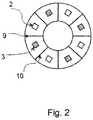
- each platform 3asupports four emitters and four detectors, equi-angularly spaced apart around the platform.
- emittersalternate with detectors.
- Each emitter 2 and each detector 3is directed radially outwardly, in a given horizontal direction, so that each emitter 2 is directed at an angle of substantially 45° to both adjacent detectors 3, and each detector 3 is directed at an angle of substantially 45° to both adjacent emitters 2. Since each emitter 2 has two adjacent detectors 3 on a given level, and each detector 3 has two adjacent emitters 2 on a given level, each emitter 2 and each detector 3 constitutes one part of two emitter-detector pairs.
- dividers 9 and 10between the emitter 2 and the detector 3 of each emitter-detector pair. These dividers may have a degree of opacity to reduce the extent to which light is transmitted directly from an emitter 2 to a detector 3 of a given emitter-detector pair.
- the eight emitter-detector pairs of each of the platforms 3aare directed in the same eight respective directions as the emitter-detector pairs of all the other platforms 3a.
- the gauge illustrated in Figures 1 and 2operates in the following manner.
- the processor with housing 4is duly programmed so that it reads the signal issuing from the detector 3 of each of the lowermost eight emitter-detector pairs. It does this whilst the emitters of each of those pairs is switched off, or is otherwise in a non-transmitting condition. It then switches on the emitters 2 of each emitter-detector pair of the lowermost platform 3a, in turn so that there is no interference in the measurements as between one emitter-detector pair and another. It then stores the difference between the reading it obtains from the detector 3 of each emitter-detector pair when the emitter 2 is in a transmitting condition to the reading it obtains from that detector 3 when the emitter 2 of the pair is not transmitting.
- the programthen analyses these results to indicate at what level of the post 1 the said difference suddenly drops, by virtue of the fact that there is no material to reflect the light from the emitter 2 into the detector 3 of a given emitter-detector pair. It also provides an indication of any difference between the results obtained from the emitter-detector pairs on a given level of platform 3a, indicative for example of whether there is any caking of snow on the post 1, also from the values of the difference signals, as well as an indication of the nature of the material, for example whether it is crisp snow, slushy snow, icy snow, or somewhere between these conditions, or whether it is a fine frost, a coarse frost or block ice with bubbles, for example.
- This procedureis completed with the emitters 2 and/or the detectors 3 switched to operate exclusively at a frequency corresponding to a wavelength of substantially 0.6 micrometers. It is then repeated with the emitters 2 and/or the detectors 3 switched to operate exclusively at a wavelength of substantially 1.1 micrometers. The procedure is then repeated with the emitters 2 and/or the detectors switched to operate exclusively at a wavelength of substantially 1.65 micrometers.
- Figure 3shows a number of curves indicating the reflectance of fine frost, coarse frost and block ice with bubbles respectively as a function of wavelength of the radiation being reflected.
- Figure 4shows a number of curves indicating the reflectance of snow at 0°C with different levels of water content respectively, as a function of wavelength of the radiation being reflected.
- gaugesmay form part of a network to cover a wide area.
- the results from such a networkmay be published over the internet.
- the illustrated gaugemay readily occur to the reader without taking the resulting construction outside the scope of the present invention, which is defined by the appended claims.
- the emitters and detectors in the illustrated gaugeare light emitters and light detectors, they may be constructed to emit and detect a different radiation or a different physical effect.
- the gaugehas been described as a device for measuring the depth of snow, the gauge may be adapted to measure the depth of other materials or fluids, especially if they are light reflective.
- the post 1may be anything from 50 cm in length to 15 m in length, or indeed outside this range, depending upon the depths of snow to be measured in different parts of the world.
- the spike 5may be about 30 cm in length.
- the processor with housing 4may be programmed to detect a malfunctioning of any of the emitters and detectors.
- the microprocessor with housing 4may be programmed so that signals transmitted by each emitter 2 may be varied, for example pulsed, and so that the signals from the corresponding detector 3 that are processed by the microprocessor are those which are correspondingly varied. This avoids the need for measurements to be taken when the emitter is in the off condition, to avoid the effects of ambient light, and to provide a greater signal to noise performance.
Landscapes
- Physics & Mathematics (AREA)
- General Physics & Mathematics (AREA)
- Electromagnetism (AREA)
- Environmental & Geological Engineering (AREA)
- Life Sciences & Earth Sciences (AREA)
- Atmospheric Sciences (AREA)
- Biodiversity & Conservation Biology (AREA)
- Ecology (AREA)
- Environmental Sciences (AREA)
- Engineering & Computer Science (AREA)
- Thermal Sciences (AREA)
- Fluid Mechanics (AREA)
- Hydrology & Water Resources (AREA)
- Length Measuring Devices By Optical Means (AREA)
- Investigating Or Analysing Materials By Optical Means (AREA)
Description
- The present invention relates to a depth gauge comprising an elongate support which is intended to be in an upright orientation when in use, N sets of emitters, where N is an integer greater than 1, each set of emitters being mounted on the elongate support and being spaced apart therealong, and N sets of detectors, each set of detectors being mounted on the elongate support and being spaced apart therealong, the 2N sets being directed in different respective directions and the emitters and the detectors being electrically connected to a processor to enable the latter to send signals to the emitters and receive signals from the detectors.
- One such gauge is described and illustrated in
US 2011/219868 A1 , for measuring the depth of snow. - The present invention seeks to provide a gauge for measuring the depth of snow, especially if the snow may become caked against the emitters and the detectors in the event of driving wind conditions in which the snow is driven against the gauge to settle on the gauge before it has reached the ground.
- Accordingly, the present invention is directed to a depth gauge having the construction set out in the opening paragraph of the present specification, in which each emitter and each detector is directed outwardly from the gauge, so that the strength of a signal received by a detector which signal has been issued by an adjacent emitter will be dependent upon the extent to which that signal has been reflected by material which is adjacent to the emitter and the detector, and in which the emitters and the detectors alternate with one another around the elongate support so as to provide 2N sets of emitter-detector pairs directed in 2N directions respectively.
- With such a construction, when it is used to provide a measure of the depth of snow, and in the event that the depth indicated by one of the sets is different from the depth indicated by the other set or one of the other sets, this is indicative that the set indicating a greater depth has snow caked on it, so that the depth indicated by that set may be ignored. Thus such a construction provides the advantage that it can distinguish between a false depth indication arising from snow which has caked onto the gauge, and a true depth indication from snow which has built up from ground level.
- The emitters and detectors may comprise light emitters and light detectors. Such a construction is especially useful to measure the depth of snow.
- The processor may be constructed to enable it to distinguish between more than two different levels of signal received from each detector. This enables the gauge to distinguish between different types of snow, for example to distinguish between crisp snow, slushy snow, and icy snow.
- The processor may be programmed to address each emitter in succession, from the intended lower end of the elongate support upwardly to the intended upper end thereof. With such a construction, the level of the detector at which the measured signal is lower than the signal from the immediately preceding detector may be indicative of the depth of the snow on the ground.
- The processor may be programmed to store the level of the signal received from a detector, whilst an adjacent emitter is in the off condition or is otherwise in a condition in which it is not transmitting, then to switch the emitter into a condition in which it is transmitting a signal, at which time it compares the level of the signal received from the detector and stores the difference in the level of that signal relative to the level of the signal when the emitter was in the off condition or was otherwise in a condition in which it was not transmitting. This provides the advantage that the difference signal is independent of the ambient light, so that it does not have an effect on the results provided by the processor, the latter thereby giving the same indication irrespective of whether the gauge is operating during daytime or night time, for example.
- Alternatively, the processor may be programmed to cause each emitter to transmit a varied signal, for example a pulsed signal, and it may be programmed to measure a correspondingly varied signal from an adjacent detector. This also provides the advantage of obtaining a measurement which is independent of the ambient light, and to give a greater signal to noise performance.
- The emitters and the detectors may be in registration with one another. This ensures that a measurement may be obtained from an emitter/detector of one set at a given level which corresponds in level to an emitter/detector of the other set or of any one of the other sets.
- A divider may be provided between the emitter and the detector of a given emitter-detector pair. The divider may have a degree of opacity relative to the signal issued by the emitter of the emitter-detector pair.
- A divider may be provided between one emitter-detector pair and an adjacent emitter-detector pair. The divider may have a degree of opacity relative to the signal issued by the emitter of the pair or the adjacent pair. This reduces the likelihood of transmission of a signal directly from an emitter to a detector instead of by way of reflection by surrounding material the depth of which is to be measured.
- An example of a depth gauge made in accordance with the present invention is illustrated in greater detail in the accompanying drawings, in which:-
Figure 1 is a side elevational view of a depth gauge embodying the present invention;Figure 2 is a cross-sectional view of the gauge in the plane indicated by the line II-II shown inFigure 1 ; andFigures 3 and4 show different explanatory graphs.Figure 1 shows a depth gauge comprising an uprightrigid post 1 made of a transparent or translucent material, along which are arranged a multiplicity of emitters uniformly spaced apart from one another, and each comprising alight emitting diode 2. A multiplicity oflight detectors 3 are also arranged along therigid post 1 uniformly spaced apart from one another and in registration with thediodes 2. Eachemitter 2 andadjacent detector 3 are in close proximity to one another. Each emitter and adjacent detector form an emitter-detector pair. Each such pair is seated on a generally horizontal platform 3a of thepost 1, there being also a multiplicity of such support platforms spaced apart along thepost 1.- The lower end of the post one is provided with a
ground spike 5, with a stability disc orflange 6 sandwiched between thespike 5 and thepost 1. - The upper end of the
post 1 is provided with a processor with a housing 4. The processor is electrically connected via multiplex circuitry (not shown) to all theemitters 2 and to all of thedetectors 3. - The upper half of the
post 1 is provided withlugs 7 from which extendguy wires 8, down to ends further from thepost 1 which ends are firmly secured to the ground. This provides thepost 1 with further stability. - As can be seen more readily from
Figure 2 , each platform 3a supports four emitters and four detectors, equi-angularly spaced apart around the platform. Thus, on each platform, progressing therearound, emitters alternate with detectors. Eachemitter 2 and eachdetector 3 is directed radially outwardly, in a given horizontal direction, so that eachemitter 2 is directed at an angle of substantially 45° to bothadjacent detectors 3, and eachdetector 3 is directed at an angle of substantially 45° to bothadjacent emitters 2. Since eachemitter 2 has twoadjacent detectors 3 on a given level, and eachdetector 3 has twoadjacent emitters 2 on a given level, eachemitter 2 and eachdetector 3 constitutes one part of two emitter-detector pairs. There aredividers emitter 2 and thedetector 3 of each emitter-detector pair. These dividers may have a degree of opacity to reduce the extent to which light is transmitted directly from anemitter 2 to adetector 3 of a given emitter-detector pair. - It will be appreciated that the eight emitter-detector pairs of each of the platforms 3a are directed in the same eight respective directions as the emitter-detector pairs of all the other platforms 3a. As a result, there are eight sets of emitter-detector pairs, with respective bisectors constituted by
dividers post 1, with an angle of 45° between adjacent dividers. - When in use, with the
spike 5 inserted into the ground so that theflange 6 is pressed against the surface of the ground and theguy wires 8 are also secured to the ground as indicated inFigure 1 , the gauge illustrated inFigures 1 and2 operates in the following manner. - The processor with housing 4 is duly programmed so that it reads the signal issuing from the
detector 3 of each of the lowermost eight emitter-detector pairs. It does this whilst the emitters of each of those pairs is switched off, or is otherwise in a non-transmitting condition. It then switches on theemitters 2 of each emitter-detector pair of the lowermost platform 3a, in turn so that there is no interference in the measurements as between one emitter-detector pair and another. It then stores the difference between the reading it obtains from thedetector 3 of each emitter-detector pair when theemitter 2 is in a transmitting condition to the reading it obtains from thatdetector 3 when theemitter 2 of the pair is not transmitting. - This is then repeated for the emitter-detector pairs of each platform 3a in succession upwardly from the bottom of the
post 1 towards the top thereof. - The program then analyses these results to indicate at what level of the
post 1 the said difference suddenly drops, by virtue of the fact that there is no material to reflect the light from theemitter 2 into thedetector 3 of a given emitter-detector pair. It also provides an indication of any difference between the results obtained from the emitter-detector pairs on a given level of platform 3a, indicative for example of whether there is any caking of snow on thepost 1, also from the values of the difference signals, as well as an indication of the nature of the material, for example whether it is crisp snow, slushy snow, icy snow, or somewhere between these conditions, or whether it is a fine frost, a coarse frost or block ice with bubbles, for example. - This procedure is completed with the
emitters 2 and/or thedetectors 3 switched to operate exclusively at a frequency corresponding to a wavelength of substantially 0.6 micrometers. It is then repeated with theemitters 2 and/or thedetectors 3 switched to operate exclusively at a wavelength of substantially 1.1 micrometers. The procedure is then repeated with theemitters 2 and/or the detectors switched to operate exclusively at a wavelength of substantially 1.65 micrometers. Figure 3 shows a number of curves indicating the reflectance of fine frost, coarse frost and block ice with bubbles respectively as a function of wavelength of the radiation being reflected.Figure 4 shows a number of curves indicating the reflectance of snow at 0°C with different levels of water content respectively, as a function of wavelength of the radiation being reflected. These graphs are fromClark, R. N., Chapter 1: Spectroscopy of Rocks and Minerals, and Principles of Spectroscopy, in Manual of Remote Sensing,.- In regard to
Figure 3 , that reference states as follows: The near-infrared spectral reflectance of A) a fine grained (∼50 µm) water frost, B) medium grained (∼200 µm) frost, C) coarse grained (400-2000 µm) frost and D) an ice block containing abundant microbubbles. The larger the effective grain size, the greater the mean photon path that photons travel in the ice, and the deeper the absorptions become. Curve D is very low in reflectance because of the large path length in ice. The ice temperatures for these spectra are 112-140 K. - In regard to
Figure 4 , that reference states as follows: A series of reflectance spectra of melting snow. The top curve (a) is at 0° C and has only a small amount of liquid water, whereas the lowest spectrum (j) is of a puddle of about 3 cm of water on top of the snow. Note in the top spectrum, there is no 1.65-µm band because of the temperature. The 1.65-µm feature is temperature dependent and decreases in strength with increasing temperature (see Clark, 1981a and references therein). Note the increasing absorption at about 0.75 µm and in the short side of the 1-µm ice band, as more liquid water forms. The liquid water becomes spectrally detectable at about spectrum e, when the UV absorption increases.
These graphs show how the different measurements at different frequencies or wavelengths can be used to indicate the nature of the material the depth of which is being measured with the gauge illustrated inFigures 1 and2 , including an indication of the change in the nature of the material at different depths. - All these indications are transmitted from the microprocessor with housing 4 remotely to a data capture centre, via wire or wireless communication, where the various values are recorded and observed so that any remedial activity that needs to take place can be appropriately directed, and so that generally a statistical record can be made.
- Many such gauges may form part of a network to cover a wide area. The results from such a network may be published over the internet.
- Numerous variations and modifications to the illustrated gauge may readily occur to the reader without taking the resulting construction outside the scope of the present invention, which is defined by the appended claims. For example, there may be only two sets of emitters and two sets of detectors spaced apart along the
post 1, or there may be three such sets of each, or more than four, for example eight. Stating this more generally, there may be N sets ofemitters 2 and N sets ofdetectors 3, to have 2N sets of emitter-detector pairs directed in 2N directions respectively, where N>1. Although the emitters and detectors in the illustrated gauge are light emitters and light detectors, they may be constructed to emit and detect a different radiation or a different physical effect. Although the gauge has been described as a device for measuring the depth of snow, the gauge may be adapted to measure the depth of other materials or fluids, especially if they are light reflective. Thepost 1 may be anything from 50 cm in length to 15 m in length, or indeed outside this range, depending upon the depths of snow to be measured in different parts of the world. Thespike 5 may be about 30 cm in length. The processor with
housing 4 may be programmed to detect a malfunctioning of any of the emitters and detectors. - The microprocessor with housing 4 may be programmed so that signals transmitted by each
emitter 2 may be varied, for example pulsed, and so that the signals from the correspondingdetector 3 that are processed by the microprocessor are those which are correspondingly varied. This avoids the need for measurements to be taken when the emitter is in the off condition, to avoid the effects of ambient light, and to provide a greater signal to noise performance.
Claims (11)
- A depth gauge comprising an elongate support (1) which is intended to be in an upright orientation when in use, N sets of emitters (2), where N is an integer greater than 1, each set of emitters being mounted on the elongate support (1) and being spaced apart therealong, and N sets of detectors (3), each set of detectors being mounted on the elongate support (1) and being spaced apart therealong, the 2N sets being directed in different respective directions and the emitters (2) and the detectors (3) being electrically connected to a processor to enable the latter to send signals to the emitters (2) and receive signals from the detectors (3),characterised in that each emitter (2) and each detector (3) is directed outwardly from the gauge, so that the strength of a signal received by a detector (3) which signal has been issued by an adjacent emitter (2) will be dependent upon the extent to which that signal has been reflected by material which is adjacent to the emitter (2) and the detector (3), andin that the emitters (2) and the detectors (3) alternate with one another around the elongate support (1) so as to provide 2N sets of emitter -detector pairs directed in 2N directions respectively.
- A depth gauge according to claim 1,characterised in that the emitters (2) and detectors (3) comprise light emitters (2) and light detectors (3).
- A depth gauge according to claim 1 or claim 2,characterised in that the processor is constructed to enable it to distinguish between more than two different levels of signal received from each detector (3).
- A depth gauge according to any preceding claim,characterised in that the processor is programmed to address each emitter (2) in succession, from the intended lower end of the elongate support (1) upwardly to the intended upper end thereof.
- A depth gauge according to any preceding claim,characterised in that the processor is programmed to store the level of the signal received from a detector (3), whilst an adjacent emitter (2) is in the off condition or is otherwise in a condition in which it is not transmitting, then to switch the emitter (2) into a condition in which it is transmitting a signal, at which time it compares the level of the signal received from the detector (3) and stores the difference in the level of that signal relative to the level of the signal when the emitter (2) was in the off condition or was otherwise in a condition in which it was not transmitting.
- A depth gauge according to any one of claims 1 to 4,characterised in that the processor is programmed to cause each emitter (2) to transmit a varied signal, for example a pulsed signal, and is programmed to measure a correspondingly varied signal from an adjacent detector (3) .
- A depth gauge according to any preceding claim,characterised in that the emitters (2) and the detectors (3) are in registration with one another.
- A depth gauge according to any preceding claim,characterised in that a divider (9 or 10) is provided between the emitter (2) and the detector (3) of a given emitter-detector pair.
- A depth gauge according to claim 8,characterised in that the divider (9 or 10) has a degree of opacity relative to the signal issued by the emitter (2) of the emitter-detector pair.
- A depth gauge according to any preceding claim,characterised in that a divider (9 or 10) is provided between one emitter-detector pair and an adjacent emitter-detector pair.
- A depth gauge according to claim 10,characterised in that the divider (9 or 10) referred to in claim 11 has a degree of opacity relative to the signal issued by the emitter (2) of the pair or the adjacent pair.
Priority Applications (1)
| Application Number | Priority Date | Filing Date | Title |
|---|---|---|---|
| EP16020413.7AEP3312551B1 (en) | 2016-10-24 | 2016-10-24 | A depth gauge |
Applications Claiming Priority (1)
| Application Number | Priority Date | Filing Date | Title |
|---|---|---|---|
| EP16020413.7AEP3312551B1 (en) | 2016-10-24 | 2016-10-24 | A depth gauge |
Publications (2)
| Publication Number | Publication Date |
|---|---|
| EP3312551A1 EP3312551A1 (en) | 2018-04-25 |
| EP3312551B1true EP3312551B1 (en) | 2019-05-15 |
Family
ID=57199867
Family Applications (1)
| Application Number | Title | Priority Date | Filing Date |
|---|---|---|---|
| EP16020413.7AActiveEP3312551B1 (en) | 2016-10-24 | 2016-10-24 | A depth gauge |
Country Status (1)
| Country | Link |
|---|---|
| EP (1) | EP3312551B1 (en) |
Families Citing this family (1)
| Publication number | Priority date | Publication date | Assignee | Title |
|---|---|---|---|---|
| CN116697943B (en)* | 2023-08-02 | 2023-09-29 | 成都信息工程大学 | A device and method for measuring snow depth |
Family Cites Families (5)
| Publication number | Priority date | Publication date | Assignee | Title |
|---|---|---|---|---|
| JPH0769437B2 (en)* | 1990-12-27 | 1995-07-31 | 中浅測器株式会社 | Snow cover |
| JP2000258557A (en)* | 1999-03-12 | 2000-09-22 | Matsushita Electric Ind Co Ltd | Snowfall sensor |
| EP1382946A1 (en)* | 2002-07-15 | 2004-01-21 | Product Innovation Limited | Level sensors |
| US20110219868A1 (en)* | 2010-03-15 | 2011-09-15 | Lane John Michael | Apparatus for detecting snow depth |
| ITBG20120005A1 (en)* | 2012-01-30 | 2013-07-31 | Flow Ing Srl | PERIODIC AUTOMATED ELECTRONIC CONTROL METHOD OF THE SNOWY CONDITIONS |
- 2016
- 2016-10-24EPEP16020413.7Apatent/EP3312551B1/enactiveActive
Non-Patent Citations (1)
| Title |
|---|
| None* |
Also Published As
| Publication number | Publication date |
|---|---|
| EP3312551A1 (en) | 2018-04-25 |
Similar Documents
| Publication | Publication Date | Title |
|---|---|---|
| US10215887B2 (en) | Depth gauge | |
| ES2313345T3 (en) | LASER RADAR DEVICE AND METHOD. | |
| US7633398B2 (en) | Apparatus and method for measuring precipitation | |
| US11185243B2 (en) | Sensor device | |
| EP0264331B1 (en) | Battle field iff method and iff system for carrying it out | |
| US4797660A (en) | Photoelectric ice accumulation monitor using dual detectors | |
| US4240208A (en) | Hand-held laser surveying rod | |
| US20120007507A1 (en) | Method and sensor arrangement for detecting the visibility outside of a motor vehicle | |
| EP3312551B1 (en) | A depth gauge | |
| US5942899A (en) | Hyperspectral radiometric mine detector based upon sensing microwave brightness temperature and interference contrast signatures | |
| CN103180720A (en) | Fluorescence sensor | |
| GB2543690A (en) | A depth gauge | |
| JP2016099339A (en) | Optical impedance modulation for fuel quantity measurement | |
| JP6788863B2 (en) | Moisture content sensor and road surface condition detector | |
| CA2946768C (en) | A depth gauge | |
| JP7179885B2 (en) | depth gauge | |
| CN207816818U (en) | The mist sensor and motor vehicle of a kind of motor vehicle for being moved on road surface | |
| JP6881944B2 (en) | Depth measuring instrument | |
| JP2021189055A (en) | ToF type distance sensor and electronic equipment | |
| EP3196676B1 (en) | Device for detecting precipitation conditions | |
| CN111945533A (en) | A non-contact road surface condition detection device | |
| US20180364168A1 (en) | Improvements in and relating to remote sensing | |
| CN101903795B (en) | Radiation sensor for detecting the position and intensity of a radiation source | |
| JP4066814B2 (en) | Satellite-mounted environment observation device | |
| CN212742121U (en) | Non-contact type road surface condition detection device |
Legal Events
| Date | Code | Title | Description |
|---|---|---|---|
| PUAI | Public reference made under article 153(3) epc to a published international application that has entered the european phase | Free format text:ORIGINAL CODE: 0009012 | |
| STAA | Information on the status of an ep patent application or granted ep patent | Free format text:STATUS: THE APPLICATION HAS BEEN PUBLISHED | |
| AK | Designated contracting states | Kind code of ref document:A1 Designated state(s):AL AT BE BG CH CY CZ DE DK EE ES FI FR GB GR HR HU IE IS IT LI LT LU LV MC MK MT NL NO PL PT RO RS SE SI SK SM TR | |
| AX | Request for extension of the european patent | Extension state:BA ME | |
| STAA | Information on the status of an ep patent application or granted ep patent | Free format text:STATUS: REQUEST FOR EXAMINATION WAS MADE | |
| 17P | Request for examination filed | Effective date:20181025 | |
| RBV | Designated contracting states (corrected) | Designated state(s):AL AT BE BG CH CY CZ DE DK EE ES FI FR GB GR HR HU IE IS IT LI LT LU LV MC MK MT NL NO PL PT RO RS SE SI SK SM TR | |
| GRAP | Despatch of communication of intention to grant a patent | Free format text:ORIGINAL CODE: EPIDOSNIGR1 | |
| STAA | Information on the status of an ep patent application or granted ep patent | Free format text:STATUS: GRANT OF PATENT IS INTENDED | |
| INTG | Intention to grant announced | Effective date:20181211 | |
| GRAS | Grant fee paid | Free format text:ORIGINAL CODE: EPIDOSNIGR3 | |
| GRAA | (expected) grant | Free format text:ORIGINAL CODE: 0009210 | |
| STAA | Information on the status of an ep patent application or granted ep patent | Free format text:STATUS: THE PATENT HAS BEEN GRANTED | |
| AK | Designated contracting states | Kind code of ref document:B1 Designated state(s):AL AT BE BG CH CY CZ DE DK EE ES FI FR GB GR HR HU IE IS IT LI LT LU LV MC MK MT NL NO PL PT RO RS SE SI SK SM TR | |
| REG | Reference to a national code | Ref country code:CH Ref legal event code:EP | |
| REG | Reference to a national code | Ref country code:CH Ref legal event code:NV Representative=s name:FELBER UND PARTNER AG, CH | |
| REG | Reference to a national code | Ref country code:DE Ref legal event code:R096 Ref document number:602016013839 Country of ref document:DE | |
| REG | Reference to a national code | Ref country code:IE Ref legal event code:FG4D | |
| REG | Reference to a national code | Ref country code:NL Ref legal event code:MP Effective date:20190515 | |
| REG | Reference to a national code | Ref country code:LT Ref legal event code:MG4D | |
| PG25 | Lapsed in a contracting state [announced via postgrant information from national office to epo] | Ref country code:FI Free format text:LAPSE BECAUSE OF FAILURE TO SUBMIT A TRANSLATION OF THE DESCRIPTION OR TO PAY THE FEE WITHIN THE PRESCRIBED TIME-LIMIT Effective date:20190515 Ref country code:NO Free format text:LAPSE BECAUSE OF FAILURE TO SUBMIT A TRANSLATION OF THE DESCRIPTION OR TO PAY THE FEE WITHIN THE PRESCRIBED TIME-LIMIT Effective date:20190815 Ref country code:ES Free format text:LAPSE BECAUSE OF FAILURE TO SUBMIT A TRANSLATION OF THE DESCRIPTION OR TO PAY THE FEE WITHIN THE PRESCRIBED TIME-LIMIT Effective date:20190515 Ref country code:PT Free format text:LAPSE BECAUSE OF FAILURE TO SUBMIT A TRANSLATION OF THE DESCRIPTION OR TO PAY THE FEE WITHIN THE PRESCRIBED TIME-LIMIT Effective date:20190915 Ref country code:SE Free format text:LAPSE BECAUSE OF FAILURE TO SUBMIT A TRANSLATION OF THE DESCRIPTION OR TO PAY THE FEE WITHIN THE PRESCRIBED TIME-LIMIT Effective date:20190515 Ref country code:AL Free format text:LAPSE BECAUSE OF FAILURE TO SUBMIT A TRANSLATION OF THE DESCRIPTION OR TO PAY THE FEE WITHIN THE PRESCRIBED TIME-LIMIT Effective date:20190515 Ref country code:NL Free format text:LAPSE BECAUSE OF FAILURE TO SUBMIT A TRANSLATION OF THE DESCRIPTION OR TO PAY THE FEE WITHIN THE PRESCRIBED TIME-LIMIT Effective date:20190515 Ref country code:HR Free format text:LAPSE BECAUSE OF FAILURE TO SUBMIT A TRANSLATION OF THE DESCRIPTION OR TO PAY THE FEE WITHIN THE PRESCRIBED TIME-LIMIT Effective date:20190515 Ref country code:LT Free format text:LAPSE BECAUSE OF FAILURE TO SUBMIT A TRANSLATION OF THE DESCRIPTION OR TO PAY THE FEE WITHIN THE PRESCRIBED TIME-LIMIT Effective date:20190515 | |
| PG25 | Lapsed in a contracting state [announced via postgrant information from national office to epo] | Ref country code:RS Free format text:LAPSE BECAUSE OF FAILURE TO SUBMIT A TRANSLATION OF THE DESCRIPTION OR TO PAY THE FEE WITHIN THE PRESCRIBED TIME-LIMIT Effective date:20190515 Ref country code:GR Free format text:LAPSE BECAUSE OF FAILURE TO SUBMIT A TRANSLATION OF THE DESCRIPTION OR TO PAY THE FEE WITHIN THE PRESCRIBED TIME-LIMIT Effective date:20190816 Ref country code:BG Free format text:LAPSE BECAUSE OF FAILURE TO SUBMIT A TRANSLATION OF THE DESCRIPTION OR TO PAY THE FEE WITHIN THE PRESCRIBED TIME-LIMIT Effective date:20190815 Ref country code:LV Free format text:LAPSE BECAUSE OF FAILURE TO SUBMIT A TRANSLATION OF THE DESCRIPTION OR TO PAY THE FEE WITHIN THE PRESCRIBED TIME-LIMIT Effective date:20190515 | |
| PG25 | Lapsed in a contracting state [announced via postgrant information from national office to epo] | Ref country code:SK Free format text:LAPSE BECAUSE OF FAILURE TO SUBMIT A TRANSLATION OF THE DESCRIPTION OR TO PAY THE FEE WITHIN THE PRESCRIBED TIME-LIMIT Effective date:20190515 Ref country code:EE Free format text:LAPSE BECAUSE OF FAILURE TO SUBMIT A TRANSLATION OF THE DESCRIPTION OR TO PAY THE FEE WITHIN THE PRESCRIBED TIME-LIMIT Effective date:20190515 Ref country code:CZ Free format text:LAPSE BECAUSE OF FAILURE TO SUBMIT A TRANSLATION OF THE DESCRIPTION OR TO PAY THE FEE WITHIN THE PRESCRIBED TIME-LIMIT Effective date:20190515 Ref country code:DK Free format text:LAPSE BECAUSE OF FAILURE TO SUBMIT A TRANSLATION OF THE DESCRIPTION OR TO PAY THE FEE WITHIN THE PRESCRIBED TIME-LIMIT Effective date:20190515 | |
| REG | Reference to a national code | Ref country code:DE Ref legal event code:R097 Ref document number:602016013839 Country of ref document:DE | |
| PG25 | Lapsed in a contracting state [announced via postgrant information from national office to epo] | Ref country code:SM Free format text:LAPSE BECAUSE OF FAILURE TO SUBMIT A TRANSLATION OF THE DESCRIPTION OR TO PAY THE FEE WITHIN THE PRESCRIBED TIME-LIMIT Effective date:20190515 | |
| PLBE | No opposition filed within time limit | Free format text:ORIGINAL CODE: 0009261 | |
| STAA | Information on the status of an ep patent application or granted ep patent | Free format text:STATUS: NO OPPOSITION FILED WITHIN TIME LIMIT | |
| PG25 | Lapsed in a contracting state [announced via postgrant information from national office to epo] | Ref country code:TR Free format text:LAPSE BECAUSE OF FAILURE TO SUBMIT A TRANSLATION OF THE DESCRIPTION OR TO PAY THE FEE WITHIN THE PRESCRIBED TIME-LIMIT Effective date:20190515 | |
| 26N | No opposition filed | Effective date:20200218 | |
| PG25 | Lapsed in a contracting state [announced via postgrant information from national office to epo] | Ref country code:PL Free format text:LAPSE BECAUSE OF FAILURE TO SUBMIT A TRANSLATION OF THE DESCRIPTION OR TO PAY THE FEE WITHIN THE PRESCRIBED TIME-LIMIT Effective date:20190515 | |
| PG25 | Lapsed in a contracting state [announced via postgrant information from national office to epo] | Ref country code:SI Free format text:LAPSE BECAUSE OF FAILURE TO SUBMIT A TRANSLATION OF THE DESCRIPTION OR TO PAY THE FEE WITHIN THE PRESCRIBED TIME-LIMIT Effective date:20190515 Ref country code:MC Free format text:LAPSE BECAUSE OF FAILURE TO SUBMIT A TRANSLATION OF THE DESCRIPTION OR TO PAY THE FEE WITHIN THE PRESCRIBED TIME-LIMIT Effective date:20190515 | |
| PG25 | Lapsed in a contracting state [announced via postgrant information from national office to epo] | Ref country code:LU Free format text:LAPSE BECAUSE OF NON-PAYMENT OF DUE FEES Effective date:20191024 | |
| REG | Reference to a national code | Ref country code:BE Ref legal event code:MM Effective date:20191031 | |
| PG25 | Lapsed in a contracting state [announced via postgrant information from national office to epo] | Ref country code:BE Free format text:LAPSE BECAUSE OF NON-PAYMENT OF DUE FEES Effective date:20191031 | |
| PG25 | Lapsed in a contracting state [announced via postgrant information from national office to epo] | Ref country code:IE Free format text:LAPSE BECAUSE OF NON-PAYMENT OF DUE FEES Effective date:20191024 | |
| REG | Reference to a national code | Ref country code:AT Ref legal event code:UEP Ref document number:1133972 Country of ref document:AT Kind code of ref document:T Effective date:20190515 | |
| PG25 | Lapsed in a contracting state [announced via postgrant information from national office to epo] | Ref country code:RO Free format text:LAPSE BECAUSE OF FAILURE TO SUBMIT A TRANSLATION OF THE DESCRIPTION OR TO PAY THE FEE WITHIN THE PRESCRIBED TIME-LIMIT Effective date:20190515 | |
| PG25 | Lapsed in a contracting state [announced via postgrant information from national office to epo] | Ref country code:CY Free format text:LAPSE BECAUSE OF FAILURE TO SUBMIT A TRANSLATION OF THE DESCRIPTION OR TO PAY THE FEE WITHIN THE PRESCRIBED TIME-LIMIT Effective date:20190515 | |
| PG25 | Lapsed in a contracting state [announced via postgrant information from national office to epo] | Ref country code:IS Free format text:LAPSE BECAUSE OF FAILURE TO SUBMIT A TRANSLATION OF THE DESCRIPTION OR TO PAY THE FEE WITHIN THE PRESCRIBED TIME-LIMIT Effective date:20190915 | |
| PG25 | Lapsed in a contracting state [announced via postgrant information from national office to epo] | Ref country code:MT Free format text:LAPSE BECAUSE OF FAILURE TO SUBMIT A TRANSLATION OF THE DESCRIPTION OR TO PAY THE FEE WITHIN THE PRESCRIBED TIME-LIMIT Effective date:20190515 Ref country code:HU Free format text:LAPSE BECAUSE OF FAILURE TO SUBMIT A TRANSLATION OF THE DESCRIPTION OR TO PAY THE FEE WITHIN THE PRESCRIBED TIME-LIMIT; INVALID AB INITIO Effective date:20161024 | |
| PG25 | Lapsed in a contracting state [announced via postgrant information from national office to epo] | Ref country code:MK Free format text:LAPSE BECAUSE OF FAILURE TO SUBMIT A TRANSLATION OF THE DESCRIPTION OR TO PAY THE FEE WITHIN THE PRESCRIBED TIME-LIMIT Effective date:20190515 | |
| PGFP | Annual fee paid to national office [announced via postgrant information from national office to epo] | Ref country code:DE Payment date:20241029 Year of fee payment:9 | |
| PGFP | Annual fee paid to national office [announced via postgrant information from national office to epo] | Ref country code:GB Payment date:20241030 Year of fee payment:9 | |
| PGFP | Annual fee paid to national office [announced via postgrant information from national office to epo] | Ref country code:FR Payment date:20241025 Year of fee payment:9 Ref country code:AT Payment date:20241025 Year of fee payment:9 | |
| PGFP | Annual fee paid to national office [announced via postgrant information from national office to epo] | Ref country code:IT Payment date:20241021 Year of fee payment:9 | |
| PGFP | Annual fee paid to national office [announced via postgrant information from national office to epo] | Ref country code:CH Payment date:20241101 Year of fee payment:9 |