EP3311902B1 - Air filter element and method for producing same - Google Patents
Air filter element and method for producing sameDownload PDFInfo
- Publication number
- EP3311902B1 EP3311902B1EP16195388.0AEP16195388AEP3311902B1EP 3311902 B1EP3311902 B1EP 3311902B1EP 16195388 AEP16195388 AEP 16195388AEP 3311902 B1EP3311902 B1EP 3311902B1
- Authority
- EP
- European Patent Office
- Prior art keywords
- filter medium
- filter element
- contour
- air filter
- filter
- Prior art date
- Legal status (The legal status is an assumption and is not a legal conclusion. Google has not performed a legal analysis and makes no representation as to the accuracy of the status listed.)
- Active
Links
- 238000004519manufacturing processMethods0.000titleclaimsdescription5
- 238000005096rolling processMethods0.000claimsdescription24
- 238000000034methodMethods0.000claimsdescription22
- 239000011796hollow space materialSubstances0.000claimsdescription3
- 238000005304joiningMethods0.000claimsdescription2
- 238000004804windingMethods0.000description16
- 238000007789sealingMethods0.000description10
- 239000000463materialSubstances0.000description7
- 239000000853adhesiveSubstances0.000description5
- 230000001070adhesive effectEffects0.000description5
- 230000000295complement effectEffects0.000description4
- 238000003780insertionMethods0.000description3
- 230000037431insertionEffects0.000description3
- 238000009434installationMethods0.000description3
- 229920001971elastomerPolymers0.000description2
- 239000000806elastomerSubstances0.000description2
- 238000001914filtrationMethods0.000description2
- 239000004033plasticSubstances0.000description2
- 229920003023plasticPolymers0.000description2
- -1polyethylenePolymers0.000description2
- 229920002635polyurethanePolymers0.000description2
- 239000004814polyurethaneSubstances0.000description2
- 239000012945sealing adhesiveSubstances0.000description2
- 235000010627Phaseolus vulgarisNutrition0.000description1
- 244000046052Phaseolus vulgarisSpecies0.000description1
- 239000004698PolyethyleneSubstances0.000description1
- 239000004743PolypropyleneSubstances0.000description1
- 230000000694effectsEffects0.000description1
- 239000012467final productSubstances0.000description1
- 239000012530fluidSubstances0.000description1
- 238000007689inspectionMethods0.000description1
- 210000003734kidneyAnatomy0.000description1
- 230000007257malfunctionEffects0.000description1
- 238000002844meltingMethods0.000description1
- 230000008018meltingEffects0.000description1
- JTJMJGYZQZDUJJ-UHFFFAOYSA-NphencyclidineChemical classC1CCCCN1C1(C=2C=CC=CC=2)CCCCC1JTJMJGYZQZDUJJ-UHFFFAOYSA-N0.000description1
- 229920000573polyethylenePolymers0.000description1
- 229920001155polypropylenePolymers0.000description1
- 238000003825pressingMethods0.000description1
- 230000001681protective effectEffects0.000description1
- 238000011179visual inspectionMethods0.000description1
Images


Classifications
- B—PERFORMING OPERATIONS; TRANSPORTING
- B01—PHYSICAL OR CHEMICAL PROCESSES OR APPARATUS IN GENERAL
- B01D—SEPARATION
- B01D46/00—Filters or filtering processes specially modified for separating dispersed particles from gases or vapours
- B01D46/24—Particle separators, e.g. dust precipitators, using rigid hollow filter bodies
- B—PERFORMING OPERATIONS; TRANSPORTING
- B01—PHYSICAL OR CHEMICAL PROCESSES OR APPARATUS IN GENERAL
- B01D—SEPARATION
- B01D46/00—Filters or filtering processes specially modified for separating dispersed particles from gases or vapours
- B01D46/52—Particle separators, e.g. dust precipitators, using filters embodying folded corrugated or wound sheet material
- B01D46/521—Particle separators, e.g. dust precipitators, using filters embodying folded corrugated or wound sheet material using folded, pleated material
- B01D46/525—Particle separators, e.g. dust precipitators, using filters embodying folded corrugated or wound sheet material using folded, pleated material which comprises flutes
- B01D46/527—Particle separators, e.g. dust precipitators, using filters embodying folded corrugated or wound sheet material using folded, pleated material which comprises flutes in wound arrangement
- B—PERFORMING OPERATIONS; TRANSPORTING
- B01—PHYSICAL OR CHEMICAL PROCESSES OR APPARATUS IN GENERAL
- B01D—SEPARATION
- B01D46/00—Filters or filtering processes specially modified for separating dispersed particles from gases or vapours
- B01D46/0001—Making filtering elements
- B—PERFORMING OPERATIONS; TRANSPORTING
- B01—PHYSICAL OR CHEMICAL PROCESSES OR APPARATUS IN GENERAL
- B01D—SEPARATION
- B01D46/00—Filters or filtering processes specially modified for separating dispersed particles from gases or vapours
- B01D46/0002—Casings; Housings; Frame constructions
- B01D46/0005—Mounting of filtering elements within casings, housings or frames
- B—PERFORMING OPERATIONS; TRANSPORTING
- B01—PHYSICAL OR CHEMICAL PROCESSES OR APPARATUS IN GENERAL
- B01D—SEPARATION
- B01D46/00—Filters or filtering processes specially modified for separating dispersed particles from gases or vapours
- B01D46/52—Particle separators, e.g. dust precipitators, using filters embodying folded corrugated or wound sheet material
- B—PERFORMING OPERATIONS; TRANSPORTING
- B01—PHYSICAL OR CHEMICAL PROCESSES OR APPARATUS IN GENERAL
- B01D—SEPARATION
- B01D2271/00—Sealings for filters specially adapted for separating dispersed particles from gases or vapours
- B01D2271/02—Gaskets, sealings
- B01D2271/027—Radial sealings
- B—PERFORMING OPERATIONS; TRANSPORTING
- B01—PHYSICAL OR CHEMICAL PROCESSES OR APPARATUS IN GENERAL
- B01D—SEPARATION
- B01D2275/00—Filter media structures for filters specially adapted for separating dispersed particles from gases or vapours
- B01D2275/20—Shape of filtering material
- B01D2275/206—Special forms, e.g. adapted to a certain housing
- B—PERFORMING OPERATIONS; TRANSPORTING
- B01—PHYSICAL OR CHEMICAL PROCESSES OR APPARATUS IN GENERAL
- B01D—SEPARATION
- B01D2279/00—Filters adapted for separating dispersed particles from gases or vapours specially modified for specific uses
- B01D2279/60—Filters adapted for separating dispersed particles from gases or vapours specially modified for specific uses for the intake of internal combustion engines or turbines
- F—MECHANICAL ENGINEERING; LIGHTING; HEATING; WEAPONS; BLASTING
- F02—COMBUSTION ENGINES; HOT-GAS OR COMBUSTION-PRODUCT ENGINE PLANTS
- F02M—SUPPLYING COMBUSTION ENGINES IN GENERAL WITH COMBUSTIBLE MIXTURES OR CONSTITUENTS THEREOF
- F02M35/00—Combustion-air cleaners, air intakes, intake silencers, or induction systems specially adapted for, or arranged on, internal-combustion engines
- F02M35/02—Air cleaners
- F02M35/024—Air cleaners using filters, e.g. moistened
- F02M35/02416—Fixing, mounting, supporting or arranging filter elements; Filter element cartridges
- F—MECHANICAL ENGINEERING; LIGHTING; HEATING; WEAPONS; BLASTING
- F02—COMBUSTION ENGINES; HOT-GAS OR COMBUSTION-PRODUCT ENGINE PLANTS
- F02M—SUPPLYING COMBUSTION ENGINES IN GENERAL WITH COMBUSTIBLE MIXTURES OR CONSTITUENTS THEREOF
- F02M35/00—Combustion-air cleaners, air intakes, intake silencers, or induction systems specially adapted for, or arranged on, internal-combustion engines
- F02M35/02—Air cleaners
- F02M35/024—Air cleaners using filters, e.g. moistened
- F02M35/02475—Air cleaners using filters, e.g. moistened characterised by the shape of the filter element
- F02M35/02483—Cylindrical, conical, oval, spherical or the like filter elements; wounded filter elements
Definitions
- the present inventionpertains to air filter elements and to methods for producing air filter elements.
- US patent no. 9,162,172 B2discloses an air cleaner including a housing and an access cover.
- the internal volume of the housingcan be reached through an opening in a side wall of the housing.
- a filter element having fluted filter mediais removable and replaceable from the air cleaner.
- the housingis constructed and arranged to cam the element into sealing engagement with the housing.
- a method of installing the filter element in the air cleanerincludes sliding a portion of the filter element against a slide surface in the housing.
- a method of servicing an air cleanerincludes tilting the filter element against a tilt surface in the housing to release a seal between the filter element and the housing.
- the filter elementcan have a handle to assist in servicing of the air cleaner.
- the housingcan have an inspection window to allow visual inspection of the internal component of the housing and to determine visually whether a filter element is installed therein.
- US patent no. 9,205,361 B2discloses an air filter element for an air filter having a tubular filter medium, the annular cross-section of which encloses an interior of the filter element and which has an inner wall that adjoins the interior of the filter element and that extends in the form of at least one convex arch and at least two concave arches, the concave arch being located between two convex arches such that the interior of the filter element has a constriction in the area of the concave arch, the constriction being adjoined by two wide zones of the interior of the filter element.
- This disclosureis not concerned with fluted filter media, nor with the problems described above in the context of US patent no. 9,162,172 B2 .
- DE 102015016236 A1discloses an air filter comprising fluted media in stacked configuration having an outer guiding rim wherein the circumferences of the guiding rim and the media comprise a convex and a concave portion.
- an air filter elementcomprising: a filter medium pack comprising a filter medium, the filter medium pack having a substantially planar first side and a substantially planar second side, the first side and second side being parallel; and a guiding rim comprising a sealing surface having at least a radially oriented component, arranged on at least one of the first side and the second side; wherein a circumference of the or each guiding rim comprises at least one convex portion and at least one concave portion; and wherein a contour of the filter medium pack corresponds to the convex portion of the guiding rim and at least part of the concave portion.
- the present inventionis based inter alia on the insight of the inventors that by providing the filter element with a guiding rim that has a sufficiently curved circumference, in particular a circumference with at least one convex portion and at least one concave portion, a more reliable seal can be obtained than when the seal is to be formed along substantially straight lines.
- the guiding rimcomprises a radially directed seal (also referred to as radial seal).
- the present inventionis also based on the further insight of the inventors that by providing the filter element with a guiding rim whose circumference has at least one convex portion and at least one concave portion, the overall symmetry of the filter element may be reduced, thus reducing the possibilities for incorrect installation of the filter element in the housing.
- the present inventionis also based on the further insight of the inventors that by having a filter medium pack whose contour corresponds to the circumference of the guiding rim at least in the convex portions, the space defined by the guiding rim(s) is optimally used to provide filtering capacity.
- the term "corresponds to”is used herein to indicate that the shape of the filter medium pack closely follows the shape of the guiding rim; the distance between the contour of the filter medium pack and the guiding rim is relatively small and does not vary considerably along the contour.
- the guiding rimpreferably stays within a distance of 2 cm, more preferably within 1 cm, and most preferably within 0.5 cm, of the contour of the filter medium pack.
- the distance between the guiding rim and the contour of the filter medium packpreferably does not vary more than 2 cm, more preferably not more than 1 cm, most preferably not more than 0.5 cm.
- the periphery of the guiding rimmay correspond to the contour of the filter medium pack over its entire length, i.e. not only over the convex portion.
- the filter medium packcomprises a rolled-up length of filter medium having a tubular shape and a core that is substantially geometrically similar to the contour.
- the filter mediamay be rolled up around a winding core, removed from the winding core, and then provided with a final core. Alternatively, the filter media may be rolled up around a core that remains in place in the final product. It is a further advantage of this embodiment that it provides increased rigidity.
- geometrically similaris used herein to designate an object of the same general shape, but at a different scale.
- substantially geometrically similaris used to indicate that the similarity of the shapes of the core and the guiding rim need not be exact, but is sufficiently strong for the core to determine the shape of the resulting rolled-up pack.
- the filter medium packcomprises z-type filter media.
- the inlet surface and the outlet surface of the filter mediaare the parallel substantially planar sides, where the ends of the "flutes" of the media are aligned.
- the contouris elongate and at least one concave portion is present along a longitudinal side of the contour. More particularly, the contour may be essentially bean-shaped or kidney-shaped. The filter element is then of the bean-shape type or kidney-shape-type.
- the filter medium packcomprises at least two separately rolled-up lengths of filter medium, the at least two separately rolled-up lengths of filter medium being held together by the guiding rim. More particularly, the contour may be essentially 8-shaped. The filter element is then of the 8-shape-type.
- the filter medium packmay advantageously be 8-shaped or the like. It is an advantage of this embodiment that the individual rolls can be cylindrical and can be obtained simply by rolling up a sheet of medium around a cylindrical core or onto itself, while the combination of several rolls still results in the desired contour having a concave part and a convex part.
- Each of the at least two separately rolled-up lengths of filter mediummay comprise a cylindrical core (the winding core onto which it was wound, or a different core inserted after removing the roll from the winding core), or it may be coreless.
- the filter medium packis rolled up so as not to leave a hollow space at its center.
- the filter medium packmay advantageously be filled up entirely with filter medium, thus increasing the filtering capacity for a given housing volume.
- a “full” filter medium packmay be obtained by rolling up the filter medium around a removable winding core, and flattening it after taking it off the roll.
- such a "full” filter medium packmay be obtained by rolling a sheet of filter medium sheet onto itself.
- an air filter systemcomprising a housing and an air filter element with an essentially bean-shaped or kidney-shaped contour as described above, the housing defining a cavity shaped so as to be able to hold the air filter element; wherein the housing comprises an access window for inserting the air filter element into said cavity and removing the air filter element from the cavity; and wherein the access window is shaped and positioned in such a way that the air filter element can be inserted and removed by a movement that comprises a rotation.
- filter elements having "bean shaped" or “kidney shaped” contoursthat the filter system may occupy an available space in a system which would not otherwise be able to hold a traditionally-shaped filter system (in particular, a cavity with a bend or corner).
- the air filter elementsmay be introduced and removed in a non-axial direction.
- the air filter elementsmay be moved towards or away from the housing along a path between obstacles, such as the pre-arranged components of an engine or machine, which would not have been possible with a standard straight shaped filter element.
- the housingmay be adapted to introduce and remove the filter element from the side (i.e., transversally rather than axially in the direction of flow of the air to be filtered), in which case a relatively small side opening may suffice to allow the filter element to slide rotatingly into or out of the housing.
- the rotational movementallows the bean-shaped or kidney-shaped air filter element to turn "around the corner" during installation of removal.
- a cornermay be present because the housing may have to be arranged in a part of a machine or engine system where the presence of other essential components leaves no room for a large, straight filter cavity.
- the bean-shaped or kidney-shaped air filter elementcan bend around an obstacle, and still be inserted or removed relatively easily.
- obstaclessuch as components of a predetermined engine arrangement (e.g., the arrangement of engine components under the hood of an automobile or a truck) may be present in the space defined by the concave portion of the filter medium pack contour during the insertion or removal trajectory of the latter.
- the access windowis shaped and positioned in such a way that, taking into account the shape of the air filter element, the air filter element can only be inserted and removed by a movement that comprises a rotation, e.g. following the curvature of the contour.
- More complex shapes, having two or more concave portions along the contour of the filter medium pack,may be used to allow the filter element to travel past more complex combinations of obstacles.
- a method for producing an air filter elementcomprising: rolling up at least one length of filter medium having a constant width, to produce a filter medium pack with a substantially planar first side and a substantially planar second side, the first side and second side being parallel; and arranging a guiding rim comprising a sealing surface having at least a radial component on at least one of the first side and the second side; wherein a circumference of the or each guiding rim comprises at least a convex portion and at least a concave portion; and wherein a contour of the filter medium pack corresponds to the convex portion of the guiding rim and at least part of the concave portion.
- the rolling upcomprises rolling the length of filter medium around a core having a shape that is substantially geometrically similar to the circumference.
- the contouris elongate and at least one concave portion is present along a longitudinal side of the contour. More particularly, the contour may be essentially bean-shaped or kidney-shaped.
- the rolling upcomprises separately rolling up at least two rolled-up lengths of filter medium around respective cylindrical cores, and joining the two separately rolled-up lengths of filter medium being together by the arranging of the guiding rim.
- the contourmay be essentially 8-shaped.
- the rolling upcomprises rolling the length of filter medium around a core, the method further comprising removing the core from the filter medium pack and deforming the filter medium pack to obtain the contour.
- Figure 1presents a plan view (top left), a cross section (bottom left), and a perspective view (right) of this embodiment.
- the illustrated air filter element 100comprises a filter medium pack 110 comprising a rolled-up length of filter medium.
- the filter medium pack 110has a substantially planar first side 111 and a substantially planar second side 112, which are parallel to each other.
- the air filter element 100is intended to be removably installed in a housing (not shown).
- the housinghas one or more openings or "windows".
- Various housing and window arrangementsare possible, including systems where the opening is accessed by removing the end of the housing where the inlet or the outlet is provided, and systems where a window on the side of the housing can be accessed.
- the "side loaders"may have their window on the narrow side or on the broad side.
- Fluted filter mediaincludes filter material having a plurality of flutes formed therein having alternating ends of adjacent flutes closed to force fluid through filter material.
- Various types of fluted filter mediaare commercially available and known to the skilled person.
- a filter medium pack of the fluted filter media type or z-type mediais known to the skilled person.
- some types of fluted filter mediaare known from US patent no. 3,025,963 to Jordan V. Bauer , US patent no. 5,895,574 to Francis Friedmann et al. , US patent no. 6,416,605 to Patrick Golden , and from US patent application publication no. US 2014/0102057 A1 .
- a filter medium pack 110 of the fluted filter media typemay for instance be obtained by rolling up a base sheet comprising generally parallel hollow tubes (flutes, original tubes) and applying a sealing adhesive between the consecutive layers of rolled-up filter medium, for instance at the side of the open ends.
- the base sheetcan for instance be composed of a flat sheet of media and an undulated sheet of media, which are attached to each other.
- First axial ends of the hollow tubesare abutting a first substantially planar side 111 of the filter medium pack 110 and second axial ends of the hollow tubes are abutting a second substantially planar side 112 of the filter medium pack 110.
- Complementary spaces/tubescan be created in between the hollow tubes when rolling up the base sheets, and are being defined in between the undulated sheet of a certain winding and the flat sheet of its subsequent winding.
- the hollow tubes and the complementary spaces/tubescan be interrupted at appropriate locations such as to force air coming in in a first tube (e.g. an original tube) at its first axial end (at the first planar side 111) to pass through the sidewall of the first tube into one or more adjacent second tubes (e.g. complementary tube(s)), the air thereafter forcing to leave the second tube(s) at the second axial end of the second tube(s) (at the second planar side 112).
- Some of these interruptionsmay be provided initially with the original tubes (e.g. closed at their second axial end), others may be provided for instance by applying the sealing adhesive (e.g. for complementary tubes, preferably near their first axial ends).
- the ends 111, 112then serve as outlet and inlet surfaces of the filter.
- airis supplied to the inlet surface, preferably but not necessarily, via a precleaning filter which may comprise a number of cyclones, and withdrawn from the outlet surface.
- a precleaning filterwhich may comprise a number of cyclones
- filter medium pack 110may be obtained by including a step of rolling up a medium that is provided in the form of a sheet.
- the air filter element 100further comprises a guiding rim 120 arranged on at least one of said first side 111 and said second side 112.
- guiding rims 120are present on both sides 111, 112, as in the illustrated case.
- At least one such guiding rim 120comprises a radially oriented sealing surface or a sealing surface having at least a radially oriented component.
- itmay have an axial component. It may be provided with a gasket, acting as a radial seal or an axial seal with at least a radial component.
- Guiding rims 120provide the sealing surface which allows the filter element 100 to sealingly engage with the inlet and/or outlet orifices of the filter system. In addition, they may contribute to the structural rigidity of the filter element 100, and they can assist the operator in correctly positioning the filter element 100 in the filter system (by virtue of their shape, and optionally by means of added guiding elements such as protrusions, grooves, tabs, and the like).
- the guiding rims 120may comprise a rigid plastic material (which may for instance be a supporting structure) such as but not only polyethylene or polypropylene, with a separate seal or gasket made of for instance a suitable elastomer, or polyurethane arranged on their sealing surface.
- a rigid plastic materialsuch as but not only polyethylene or polypropylene
- a separate seal or gasketmade of for instance a suitable elastomer, or polyurethane arranged on their sealing surface.
- the guiding rims 120may be made of a material that can serve as a seal, in particular a suitable elastomer such as polyurethane.
- Guiding rims 120may be separately manufactured and attached to the filter medium pack 110, or they may be molded in place (i.e. overmolded onto the filter medium pack 110 ) if the melting and curing properties of the chosen material allow this.
- the air filter as seen in the plan viewhas an elongate shape.
- the circumference of each guiding rim 120comprises at least one convex portion and at least one concave portion.
- the left-hand side and the right-hand side of the contourare convex (viewed from the outside of the filter element) while the top side and the bottom side of the contour (the longitudinal sides) comprise a concave central portion.
- the contour of the filter medium pack 110(as seen in cross-section in any plane parallel to the planar sides 111, 112 ) corresponds to (i.e., it closely matches) the entire circumference of the guiding rim 120.
- FIG. 2presents an exploded view of the filter element according to the first embodiment.
- the filter medium pack 110has a tubular shape, i.e. its shape closes onto itself around a hollow center, and comprises a core 130 that is substantially geometrically similar to the outer contour of the filter medium pack 110.
- Figure 2shows the guiding rims 120 on each side of the filter medium 110 and the core 130 to be placed at the center of the filter medium 110.
- the guiding rimsmay be comprised in an element 125 that covers part of the relevant side 111 or 112, for example to avoid telescopic deformation of the rolled up filter medium pack 110; to increase structural rigidity, the element 125 may also help to keep the core 130 in place.
- Figure 3schematically illustrates a first method of producing the filter element 100 according to the first embodiment.
- the methodcomprises rolling up a length of filter medium having a constant width, to produce a filter medium pack 110 with a substantially planar first side 111 and a substantially planar second side 112, the first side 111 and second side 112 being parallel.
- the rolling upcomprises rolling the length of filter medium around a core 130 having a shape that is substantially geometrically similar to the desired circumference.
- the sheetis kept under appropriate tension and pressed onto the core 130 and subsequently onto the increasing pack by suitably arranged reciprocating rollers 151-154.
- Adhesive(not shown) is applied to the sheet to keep the consecutive layers together.
- a guiding rim 120 as described aboveis arranged on at least one of the first side 111 and the second side 112 (not illustrated in Figure 3 ).
- Figure 4schematically illustrates a second method of producing the filter element according to the first embodiment.
- a length of filter medium having a constant widthis rolled up around an oval or obround winding core, to produce a filter medium pack 110 with a substantially planar first side 111 and a substantially planar second side 112, the first side 111 and second side 112 being parallel.
- the tensioning and pressing of the filter medium sheetis less complex than in the case illustrated in Figure 3 .
- adhesiveis applied to the sheet to keep the consecutive layers together.
- the resulting filter medium pack 110has an elongate shape without concave portions, and a hollow center.
- a core 130 that represents the desired contour shape by being substantially geometrically similar to itis inserted into the said hollow center of the filter medium pack 110.
- the filter medium pack 110 with the core 130is placed into an appropriately shaped press-mold 160, which has protrusions corresponding to the desired concave portions of the contour.
- the press-mold 160is closed to force the filter medium pack 110 into the desired shape. As this deformation inevitably causes some sliding of the layers of filter medium in the filter medium pack 110, this step should be completed before the applied adhesive has completely cured.
- a guiding rim 120 as described aboveis arranged on at least one of the first side 111 and the second side 112.
- Figure 5presents a plan view (top left), a cross section (bottom left), and a perspective view (right) of this embodiment.
- the illustrated air filter element 100comprises a filter medium pack 110 comprising two separately rolled-up lengths of filter medium.
- the resulting filter medium pack 110has a substantially planar first side 111 and a substantially planar second side 112, which are parallel to each other.
- the filter mediumis preferably of the "fluted filter media" type.
- the air filter element 100further comprises a guiding rim 120 arranged on at least one of said first side 111 and said second side 112.
- guiding rims 120are present on both sides 111, 112, as in the illustrated case.
- the illustrated filter medium pack 110consists of two separately rolled-up lengths of filter medium
- the guiding rim 120has the additional function of keeping these two rolls together to form one pack.
- the air filter element 100has an elongate shape.
- the circumference of each guiding rim 120comprises at least one convex portion and at least one concave portion.
- the left-hand side and the right-hand side of the contourare convex (viewed from the outside of the filter element) while the top side and the bottom side of the contour (the longitudinal sides) comprise a concave central portion.
- the contour of the filter medium pack 110corresponds to (i.e., it closely matches) the convex portion of the circumference of the guiding rim 120.
- the concave portionsare situated where the two rolls of media meet each other, the contour of the filter medium pack 110 does not strictly follow the circumference of the guiding rim 120 in these portions.
- FIG. 6presents an exploded view of the filter element according to the second embodiment.
- the filter medium pack 110consists of two tubular cylinders, i.e. cylinders with a hollow center, and comprises corresponding cylindrical cores 130.
- Figure 6also shows the guiding rims 120 on each side of the filter medium 110 that keeps the rolls of filter medium 110 together and the cores 130 to be placed at the center of the rolls of filter medium 110.
- a third embodiment of the filter element according to the present inventionwill now be described with reference to Figures 7 and 8 .
- This embodimentwill be described with emphasis on the elements that differ from those of the first embodiment.
- Figure 7presents a plan view (top left), a cross section (bottom left), and a perspective view (right) of this embodiment.
- the illustrated air filter element 100comprises a filter medium pack 110 comprising a rolled-up length of filter medium.
- the filter medium pack 110has a substantially planar first side 111 and a substantially planar second side 112, which are parallel to each other.
- the filter mediumis again preferably of the "fluted filter media" type.
- the air filter element 100further comprises a guiding rim 120 arranged on at least one of said first side 111 and said second side 112.
- guiding rims 120are present on both sides 111, 112, as in the illustrated case.
- the air filter element 100has an elongate shape.
- the circumference of each guiding rim 120comprises at least one convex portion and at least one concave portion.
- the left-hand side and the right-hand side of the contourare convex (viewed from the outside of the filter element) while the top side of the contour is straight and the bottom side of the contour comprises a concave central portion.
- the contour of the filter medium pack 110corresponds to (i.e., it closely matches) the entire circumference of the guiding rim 120.
- FIG 8presents an exploded view of the filter element according to the first embodiment.
- the filter medium pack 110has a tubular shape, i.e. its shape closes onto itself around a hollow center, and comprises a core 130 that is substantially geometrically similar to the outer contour of the filter medium pack 110.
- Figure 8shows the guiding rims 120 on each side of the filter medium 110 and the core 130 to be placed at the center of the filter medium 110.
- a fourth embodiment of the filter element according to the present inventionwill now be described with reference to Figures 9-11 . This embodiment will be described with emphasis on the elements that differ from those of the first embodiment.
- Figure 9presents a plan view (top left), a cross section (bottom left), and a perspective view (right) of this embodiment.
- the illustrated air filter element 100comprises a filter medium pack 110 comprising a rolled-up length of filter medium.
- the filter medium pack 110has a substantially planar first side 111 and a substantially planar second side 112, which are parallel to each other.
- the filter mediumis again preferably of the "fluted filter media" type.
- the air filter element 100further comprises a guiding rim 120 arranged on at least one of said first side 111 and said second side 112.
- guiding rims 120are present on both sides 111, 112, as in the illustrated case.
- the air filter element 100has an elongate shape.
- the circumference of each guiding rim 120comprises at least one convex portion and at least one concave portion.
- the top side, the left-hand side, and the right-hand side of the contourare convex (viewed from the outside of the filter element) while the bottom side of the contour comprises a concave central portion.
- the contour of the filter medium pack 110corresponds to (i.e., it closely matches) the entire circumference of the guiding rim 120.
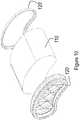
- Figure 10presents an exploded view of the filter element according to the first embodiment.
- the filter medium pack 110is completely filled, i.e. it does not have a hollow center, and there is no core in this case.
- Figure 10also shows the guiding rims 120 on each side of the filter medium 110.
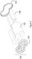
- Figure 11schematically illustrates a method of producing the filter element according to the fourth embodiment.
- a length of filter medium having a constant widthis rolled up around a cylindrical winding core, to produce a filter medium pack 110 with a substantially planar first side 111 and a substantially planar second side 112, the first side 111 and second side 112 being parallel.
- the tensioning of the filter medium sheetis less complex than in the case illustrated in Figure 3 .
- adhesiveis applied to the sheet to keep the consecutive layers together.
- the resulting filter medium pack 110has a cylindrical shape without concave portions, and a hollow center.
- a first step 2010the filter medium pack 110 with the hollow center is placed into an appropriately shaped press-mold 160, which has protrusions and cavities corresponding to the desired shape of the contour.
- a second step 2020the press-mold 160, is closed to force the filter medium pack 110 into the desired shape. As this deformation inevitably causes some sliding of the layers of filter medium in the filter medium pack 110, this step should be completed before the applied adhesive has completely cured.
- a guiding rim 120 as described aboveis arranged on at least one of the first side 111 and the second side 112.
- Figure 12presents two perspective views of an air filter system comprising an air filter element according to an embodiment of the present invention
- Figure 13presents two further perspective views of the air filter element depicted in Figure 12
- the air filter element illustrated in Figures 12 and 13has a coreless kidney-shaped or bean-shaped filter media pack 110.
- a guiding rim 120 with a sealing surfaceis provided at one end.
- a handle 170is provided across a concave portion of the contour.
- a handlemay be obtained very simply by providing a bar or strip of material that bridges a concave portion of the contour, such that it can easily be grasped by a human operator by slipping one's fingers in the cavity behind the handle.
- the handlemay be flexible and attached after production of the filter element. It may for instance be glued on the outer side of the media pack or on an outer protection layer thereof in a/the concave portion.
- a further protection layer or envelope, also called shell, of the filter medium packcan be provided surrounding its radial outer surface.
- the protection layer or envelopecan extend over a limited distance or over the whole length of the media pack, providing a rigid or more rigid housing of the media pack.
- This protection layercan be made of hard material such as plastic, or for instance out of a protective cardboard.
- the handlecan also be formed integrally with the protection envelope.
- the protection envelope or shellcan moreover be integrally formed with the guiding rim or a support structure comprised in the guiding rim.
Landscapes
- Chemical & Material Sciences (AREA)
- Chemical Kinetics & Catalysis (AREA)
- Filtering Of Dispersed Particles In Gases (AREA)
- Filtering Materials (AREA)
Description
- The present invention pertains to air filter elements and to methods for producing air filter elements.
US patent no. 9,162,172 B2 - It has been found that the sealing of filter elements of the type disclosed in
US patent no. 9,162,172 B2 US patent no. 9,162,172 B2 US patent no. 9,205,361 B2 US patent no. 9,162,172 B2 DE 102015016236 A1 discloses an air filter comprising fluted media in stacked configuration having an outer guiding rim wherein the circumferences of the guiding rim and the media comprise a convex and a concave portion.- It is an object of embodiments of the present invention to provide a filter element with improved sealing characteristics. It is a further object of embodiments of the present invention to reduce the risk of incorrect installation of filter elements in filter systems.
- According to an aspect of the present invention, there is provided an air filter element comprising: a filter medium pack comprising a filter medium, the filter medium pack having a substantially planar first side and a substantially planar second side, the first side and second side being parallel; and a guiding rim comprising a sealing surface having at least a radially oriented component, arranged on at least one of the first side and the second side; wherein a circumference of the or each guiding rim comprises at least one convex portion and at least one concave portion; and wherein a contour of the filter medium pack corresponds to the convex portion of the guiding rim and at least part of the concave portion.
- The present invention is basedinter alia on the insight of the inventors that by providing the filter element with a guiding rim that has a sufficiently curved circumference, in particular a circumference with at least one convex portion and at least one concave portion, a more reliable seal can be obtained than when the seal is to be formed along substantially straight lines. The guiding rim comprises a radially directed seal (also referred to as radial seal).
- The present invention is also based on the further insight of the inventors that by providing the filter element with a guiding rim whose circumference has at least one convex portion and at least one concave portion, the overall symmetry of the filter element may be reduced, thus reducing the possibilities for incorrect installation of the filter element in the housing.
- The present invention is also based on the further insight of the inventors that by having a filter medium pack whose contour corresponds to the circumference of the guiding rim at least in the convex portions, the space defined by the guiding rim(s) is optimally used to provide filtering capacity. The term "corresponds to" is used herein to indicate that the shape of the filter medium pack closely follows the shape of the guiding rim; the distance between the contour of the filter medium pack and the guiding rim is relatively small and does not vary considerably along the contour. Along the convex portion of the periphery, the guiding rim preferably stays within a distance of 2 cm, more preferably within 1 cm, and most preferably within 0.5 cm, of the contour of the filter medium pack. Along said convex portion of the periphery, the distance between the guiding rim and the contour of the filter medium pack preferably does not vary more than 2 cm, more preferably not more than 1 cm, most preferably not more than 0.5 cm. Optionally, the periphery of the guiding rim may correspond to the contour of the filter medium pack over its entire length, i.e. not only over the convex portion.
- It is a further advantage of a filter medium pack with a contour that has a concave portion, that the hollow space thus created is a very suitable for the placement of a handle to facilitate installing or removing the filter element.
- In an embodiment of the air filter element according to the present invention, the filter medium pack comprises a rolled-up length of filter medium having a tubular shape and a core that is substantially geometrically similar to the contour.
- It is an advantage of this embodiment that relatively complex contours can be obtained by rolling up filter media around a judiciously designed core. The filter media may be rolled up around a winding core, removed from the winding core, and then provided with a final core. Alternatively, the filter media may be rolled up around a core that remains in place in the final product. It is a further advantage of this embodiment that it provides increased rigidity. The term "geometrically similar" is used herein to designate an object of the same general shape, but at a different scale. The term "substantially geometrically similar" is used to indicate that the similarity of the shapes of the core and the guiding rim need not be exact, but is sufficiently strong for the core to determine the shape of the resulting rolled-up pack.
- The filter medium pack comprises z-type filter media.
- In arrangements of this type, the inlet surface and the outlet surface of the filter media are the parallel substantially planar sides, where the ends of the "flutes" of the media are aligned. In an embodiment of the air filter element according to the present invention, the contour is elongate and at least one concave portion is present along a longitudinal side of the contour. More particularly, the contour may be essentially bean-shaped or kidney-shaped. The filter element is then of the bean-shape type or kidney-shape-type.
- It is an advantage of this embodiment that a degree of asymmetry can be introduced in the design with minimal added complexity.
- In an embodiment of the air filter element according to the present invention, the filter medium pack comprises at least two separately rolled-up lengths of filter medium, the at least two separately rolled-up lengths of filter medium being held together by the guiding rim. More particularly, the contour may be essentially 8-shaped. The filter element is then of the 8-shape-type.
- This embodiment is based inter alia on the insight of the inventors that the filter medium pack may advantageously be 8-shaped or the like. It is an advantage of this embodiment that the individual rolls can be cylindrical and can be obtained simply by rolling up a sheet of medium around a cylindrical core or onto itself, while the combination of several rolls still results in the desired contour having a concave part and a convex part. Each of the at least two separately rolled-up lengths of filter medium may comprise a cylindrical core (the winding core onto which it was wound, or a different core inserted after removing the roll from the winding core), or it may be coreless.
- In an embodiment of the air filter element according to the present invention, the filter medium pack is rolled up so as not to leave a hollow space at its center.
- As filter medium packs consisting of certain types of filter media, such as fluted or z-type filter media, do not require a tubular shape in order to supply or withdraw air from the hollow center (as is the case in the pleated-medium examples disclosed in
US patent no. 9,205,361 B2 - According to an aspect of the present invention, there is provided an air filter system comprising a housing and an air filter element with an essentially bean-shaped or kidney-shaped contour as described above, the housing defining a cavity shaped so as to be able to hold the air filter element; wherein the housing comprises an access window for inserting the air filter element into said cavity and removing the air filter element from the cavity; and wherein the access window is shaped and positioned in such a way that the air filter element can be inserted and removed by a movement that comprises a rotation.
- It is a particular advantage of filter elements having "bean shaped" or "kidney shaped" contours that the filter system may occupy an available space in a system which would not otherwise be able to hold a traditionally-shaped filter system (in particular, a cavity with a bend or corner). Moreover, the air filter elements may be introduced and removed in a non-axial direction. Also, the air filter elements may be moved towards or away from the housing along a path between obstacles, such as the pre-arranged components of an engine or machine, which would not have been possible with a standard straight shaped filter element.
- In such cases, the housing may be adapted to introduce and remove the filter element from the side (i.e., transversally rather than axially in the direction of flow of the air to be filtered), in which case a relatively small side opening may suffice to allow the filter element to slide rotatingly into or out of the housing. The rotational movement allows the bean-shaped or kidney-shaped air filter element to turn "around the corner" during installation of removal. Such a corner may be present because the housing may have to be arranged in a part of a machine or engine system where the presence of other essential components leaves no room for a large, straight filter cavity. The bean-shaped or kidney-shaped air filter element can bend around an obstacle, and still be inserted or removed relatively easily. Accordingly, obstacles such as components of a predetermined engine arrangement (e.g., the arrangement of engine components under the hood of an automobile or a truck) may be present in the space defined by the concave portion of the filter medium pack contour during the insertion or removal trajectory of the latter. In some embodiments, the access window is shaped and positioned in such a way that, taking into account the shape of the air filter element, the air filter element can only be inserted and removed by a movement that comprises a rotation, e.g. following the curvature of the contour. More complex shapes, having two or more concave portions along the contour of the filter medium pack, may be used to allow the filter element to travel past more complex combinations of obstacles.
- According to an aspect of the present invention, there is provided a method for producing an air filter element, the method comprising: rolling up at least one length of filter medium having a constant width, to produce a filter medium pack with a substantially planar first side and a substantially planar second side, the first side and second side being parallel; and arranging a guiding rim comprising a sealing surface having at least a radial component on at least one of the first side and the second side; wherein a circumference of the or each guiding rim comprises at least a convex portion and at least a concave portion; and wherein a contour of the filter medium pack corresponds to the convex portion of the guiding rim and at least part of the concave portion.
- In an embodiment of the method according to the present invention, the rolling up comprises rolling the length of filter medium around a core having a shape that is substantially geometrically similar to the circumference.
- In a particular embodiment, the contour is elongate and at least one concave portion is present along a longitudinal side of the contour. More particularly, the contour may be essentially bean-shaped or kidney-shaped.
- In an embodiment of the method according to the present invention, the rolling up comprises separately rolling up at least two rolled-up lengths of filter medium around respective cylindrical cores, and joining the two separately rolled-up lengths of filter medium being together by the arranging of the guiding rim. More particularly, the contour may be essentially 8-shaped.
- In an embodiment of the method according to the present invention, the rolling up comprises rolling the length of filter medium around a core, the method further comprising removing the core from the filter medium pack and deforming the filter medium pack to obtain the contour.
- The technical effects and advantages of embodiments of the method according to the present invention correspondmutatis mutandis to those of the corresponding embodiments of the filter element according to the present invention.
- These and other features and advantages of embodiments of the present invention will be described in more detail with reference to the attached drawings, in which:
Figure 1 presents a plan view, a cross section, and a perspective view of a filter element according to a first embodiment of the present invention;Figure 2 presents an exploded view of the filter element according to the embodiment ofFigure 1 ;Figure 3 schematically illustrates a first method of producing the filter element according to the embodiment ofFigure 1 ;Figure 4 schematically illustrates a second method of producing the filter element according to the embodiment ofFigure 1 ;Figure 5 presents a plan view, a cross section, and a perspective view of a filter element according to a second embodiment of the present invention;Figure 6 presents an exploded view of the filter element according to the embodiment ofFigure 2 ;Figure 7 presents a plan view, a cross section, and a perspective view of a filter element according to a third embodiment of the present invention;Figure 8 presents an exploded view of the filter element according to the embodiment ofFigure 7 ;Figure 9 presents a plan view, a cross section, and a perspective view of a filter element according to a fourth embodiment of the present invention;Figure 10 presents an exploded view of the filter element according to the embodiment ofFigure 9 ;Figure 11 schematically illustrates a method of producing the filter element according to the embodiment ofFigure 10 ;Figure 12 presents two perspective views of an air filter system comprising an air filter element according to an embodiment of the present invention; andFigure 13 presents two further perspective views of the air filter element depicted inFigure 12 .- A first embodiment of the filter element according to the present invention will now be described with reference to
Figures 1-4 . Figure 1 presents a plan view (top left), a cross section (bottom left), and a perspective view (right) of this embodiment.- The illustrated
air filter element 100 comprises afilter medium pack 110 comprising a rolled-up length of filter medium. Thefilter medium pack 110 has a substantially planarfirst side 111 and a substantially planarsecond side 112, which are parallel to each other. Theair filter element 100 is intended to be removably installed in a housing (not shown). To allow insertion or removal of theair filter element 100, the housing has one or more openings or "windows". Various housing and window arrangements are possible, including systems where the opening is accessed by removing the end of the housing where the inlet or the outlet is provided, and systems where a window on the side of the housing can be accessed. For filter medium pack designs that have an elongate contour, the "side loaders" may have their window on the narrow side or on the broad side. - Fluted filter media includes filter material having a plurality of flutes formed therein having alternating ends of adjacent flutes closed to force fluid through filter material. Various types of fluted filter media are commercially available and known to the skilled person.
- A filter medium pack of the fluted filter media type or z-type media is known to the skilled person. For example, some types of fluted filter media are known from
US patent no. 3,025,963 to Jordan V. Bauer ,US patent no. 5,895,574 to Francis Friedmann et al. ,US patent no. 6,416,605 to Patrick Golden , and from US patent application publication no.US 2014/0102057 A1 . Afilter medium pack 110 of the fluted filter media type may for instance be obtained by rolling up a base sheet comprising generally parallel hollow tubes (flutes, original tubes) and applying a sealing adhesive between the consecutive layers of rolled-up filter medium, for instance at the side of the open ends. The base sheet can for instance be composed of a flat sheet of media and an undulated sheet of media, which are attached to each other. First axial ends of the hollow tubes are abutting a first substantiallyplanar side 111 of thefilter medium pack 110 and second axial ends of the hollow tubes are abutting a second substantiallyplanar side 112 of thefilter medium pack 110. Complementary spaces/tubes can be created in between the hollow tubes when rolling up the base sheets, and are being defined in between the undulated sheet of a certain winding and the flat sheet of its subsequent winding. - The hollow tubes and the complementary spaces/tubes can be interrupted at appropriate locations such as to force air coming in in a first tube (e.g. an original tube) at its first axial end (at the first planar side 111) to pass through the sidewall of the first tube into one or more adjacent second tubes (e.g. complementary tube(s)), the air thereafter forcing to leave the second tube(s) at the second axial end of the second tube(s) (at the second planar side 112). Some of these interruptions may be provided initially with the original tubes (e.g. closed at their second axial end), others may be provided for instance by applying the sealing adhesive (e.g. for complementary tubes, preferably near their first axial ends). The ends111, 112 then serve as outlet and inlet surfaces of the filter. When the
filter element 100 is installed in the housing of the filter system of which it forms a part, air is supplied to the inlet surface, preferably but not necessarily, via a precleaning filter which may comprise a number of cyclones, and withdrawn from the outlet surface. - Likewise, other types of filter
medium pack 110 may be obtained by including a step of rolling up a medium that is provided in the form of a sheet. - The
air filter element 100 further comprises a guidingrim 120 arranged on at least one of saidfirst side 111 and saidsecond side 112. Preferably, guidingrims 120 are present on bothsides such guiding rim 120 comprises a radially oriented sealing surface or a sealing surface having at least a radially oriented component. In addition, it may have an axial component. It may be provided with a gasket, acting as a radial seal or an axial seal with at least a radial component. - Guiding
rims 120 provide the sealing surface which allows thefilter element 100 to sealingly engage with the inlet and/or outlet orifices of the filter system. In addition, they may contribute to the structural rigidity of thefilter element 100, and they can assist the operator in correctly positioning thefilter element 100 in the filter system (by virtue of their shape, and optionally by means of added guiding elements such as protrusions, grooves, tabs, and the like). - The guiding
rims 120 may comprise a rigid plastic material (which may for instance be a supporting structure) such as but not only polyethylene or polypropylene, with a separate seal or gasket made of for instance a suitable elastomer, or polyurethane arranged on their sealing surface. Alternatively, the guidingrims 120 may be made of a material that can serve as a seal, in particular a suitable elastomer such as polyurethane. - Guiding
rims 120 may be separately manufactured and attached to thefilter medium pack 110, or they may be molded in place (i.e. overmolded onto the filter medium pack110) if the melting and curing properties of the chosen material allow this. - In the illustrated case, the air filter as seen in the plan view has an elongate shape. The circumference of each guiding
rim 120 comprises at least one convex portion and at least one concave portion. With reference to the orientation of the plan view for the present purpose, it can clearly be seen in the illustrated case that the left-hand side and the right-hand side of the contour are convex (viewed from the outside of the filter element) while the top side and the bottom side of the contour (the longitudinal sides) comprise a concave central portion. In the illustrated case, the contour of the filter medium pack110 (as seen in cross-section in any plane parallel to theplanar sides 111, 112) corresponds to (i.e., it closely matches) the entire circumference of the guidingrim 120. Figure 2 presents an exploded view of the filter element according to the first embodiment. Thefilter medium pack 110 has a tubular shape, i.e. its shape closes onto itself around a hollow center, and comprises a core130 that is substantially geometrically similar to the outer contour of thefilter medium pack 110.Figure 2 shows the guidingrims 120 on each side of thefilter medium 110 and thecore 130 to be placed at the center of thefilter medium 110. The guiding rims may be comprised in anelement 125 that covers part of therelevant side filter medium pack 110; to increase structural rigidity, theelement 125 may also help to keep the core130 in place.Figure 3 schematically illustrates a first method of producing thefilter element 100 according to the first embodiment. The method comprises rolling up a length of filter medium having a constant width, to produce afilter medium pack 110 with a substantially planarfirst side 111 and a substantially planarsecond side 112, thefirst side 111 andsecond side 112 being parallel. The rolling up comprises rolling the length of filter medium around acore 130 having a shape that is substantially geometrically similar to the desired circumference. In order to achieve a sufficiently tight winding, the sheet is kept under appropriate tension and pressed onto thecore 130 and subsequently onto the increasing pack by suitably arranged reciprocating rollers151-154. Adhesive (not shown) is applied to the sheet to keep the consecutive layers together.- Once a
filter medium pack 110 of the desired shape and size has been obtained, a guidingrim 120 as described above is arranged on at least one of thefirst side 111 and the second side112 (not illustrated inFigure 3 ). Figure 4 schematically illustrates a second method of producing the filter element according to the first embodiment.- In a preliminary step (not illustrated), a length of filter medium having a constant width is rolled up around an oval or obround winding core, to produce a
filter medium pack 110 with a substantially planarfirst side 111 and a substantially planarsecond side 112, thefirst side 111 andsecond side 112 being parallel. As the winding core is oval or obround the tensioning and pressing of the filter medium sheet is less complex than in the case illustrated inFigure 3 . During the winding operation, adhesive is applied to the sheet to keep the consecutive layers together. After removal from the winding core, the resultingfilter medium pack 110 has an elongate shape without concave portions, and a hollow center. - In a
first step 1010, acore 130 that represents the desired contour shape by being substantially geometrically similar to it is inserted into the said hollow center of thefilter medium pack 110. In asecond step 1020 thefilter medium pack 110 with thecore 130 is placed into an appropriately shaped press-mold 160, which has protrusions corresponding to the desired concave portions of the contour. In athird step 1030, the press-mold 160, is closed to force thefilter medium pack 110 into the desired shape. As this deformation inevitably causes some sliding of the layers of filter medium in thefilter medium pack 110, this step should be completed before the applied adhesive has completely cured. - In a subsequent step (not illustrated), a guiding
rim 120 as described above is arranged on at least one of thefirst side 111 and thesecond side 112. - A second embodiment of the filter element according to the present invention will now be described with reference to
Figures 5 and6 . This embodiment will be described with emphasis on the elements that differ from those of the first embodiment. Figure 5 presents a plan view (top left), a cross section (bottom left), and a perspective view (right) of this embodiment.- The illustrated
air filter element 100 comprises afilter medium pack 110 comprising two separately rolled-up lengths of filter medium. The resultingfilter medium pack 110 has a substantially planarfirst side 111 and a substantially planarsecond side 112, which are parallel to each other. As before, the filter medium is preferably of the "fluted filter media" type. - The
air filter element 100 further comprises a guidingrim 120 arranged on at least one of saidfirst side 111 and saidsecond side 112. Preferably, guidingrims 120 are present on bothsides filter medium pack 110 consists of two separately rolled-up lengths of filter medium, the guidingrim 120 has the additional function of keeping these two rolls together to form one pack. - In the illustrated case, the
air filter element 100 has an elongate shape. The circumference of each guidingrim 120 comprises at least one convex portion and at least one concave portion. With reference to the orientation of the plan view for the present purpose, it can clearly be seen in the illustrated case that the left-hand side and the right-hand side of the contour are convex (viewed from the outside of the filter element) while the top side and the bottom side of the contour (the longitudinal sides) comprise a concave central portion. In the illustrated case, the contour of thefilter medium pack 110 corresponds to (i.e., it closely matches) the convex portion of the circumference of the guidingrim 120. However, as the concave portions are situated where the two rolls of media meet each other, the contour of thefilter medium pack 110 does not strictly follow the circumference of the guidingrim 120 in these portions. Figure 6 presents an exploded view of the filter element according to the second embodiment. Thefilter medium pack 110 consists of two tubular cylinders, i.e. cylinders with a hollow center, and comprises correspondingcylindrical cores 130.Figure 6 also shows the guidingrims 120 on each side of thefilter medium 110 that keeps the rolls offilter medium 110 together and thecores 130 to be placed at the center of the rolls offilter medium 110.- A third embodiment of the filter element according to the present invention will now be described with reference to
Figures 7 and8 . This embodiment will be described with emphasis on the elements that differ from those of the first embodiment. Figure 7 presents a plan view (top left), a cross section (bottom left), and a perspective view (right) of this embodiment.- The illustrated
air filter element 100 comprises afilter medium pack 110 comprising a rolled-up length of filter medium. Thefilter medium pack 110 has a substantially planarfirst side 111 and a substantially planarsecond side 112, which are parallel to each other. The filter medium is again preferably of the "fluted filter media" type. - The
air filter element 100 further comprises a guidingrim 120 arranged on at least one of saidfirst side 111 and saidsecond side 112. Preferably, guidingrims 120 are present on bothsides - In the illustrated case, the
air filter element 100 has an elongate shape. The circumference of each guidingrim 120 comprises at least one convex portion and at least one concave portion. With reference to the orientation of the plan view for the present purpose, it can clearly be seen in the illustrated case that the left-hand side and the right-hand side of the contour are convex (viewed from the outside of the filter element) while the top side of the contour is straight and the bottom side of the contour comprises a concave central portion. In the illustrated case, the contour of thefilter medium pack 110 corresponds to (i.e., it closely matches) the entire circumference of the guidingrim 120. Figure 8 presents an exploded view of the filter element according to the first embodiment. Thefilter medium pack 110 has a tubular shape, i.e. its shape closes onto itself around a hollow center, and comprises a core130 that is substantially geometrically similar to the outer contour of thefilter medium pack 110.Figure 8 shows the guidingrims 120 on each side of thefilter medium 110 and thecore 130 to be placed at the center of thefilter medium 110.- A fourth embodiment of the filter element according to the present invention will now be described with reference to
Figures 9-11 . This embodiment will be described with emphasis on the elements that differ from those of the first embodiment. Figure 9 presents a plan view (top left), a cross section (bottom left), and a perspective view (right) of this embodiment.- The illustrated
air filter element 100 comprises afilter medium pack 110 comprising a rolled-up length of filter medium. Thefilter medium pack 110 has a substantially planarfirst side 111 and a substantially planarsecond side 112, which are parallel to each other. The filter medium is again preferably of the "fluted filter media" type. - The
air filter element 100 further comprises a guidingrim 120 arranged on at least one of saidfirst side 111 and saidsecond side 112. Preferably, guidingrims 120 are present on bothsides - In the illustrated case, the
air filter element 100 has an elongate shape. The circumference of each guidingrim 120 comprises at least one convex portion and at least one concave portion. With reference to the orientation of the plan view for the present purpose, it can clearly be seen in the illustrated case that the top side, the left-hand side, and the right-hand side of the contour are convex (viewed from the outside of the filter element) while the bottom side of the contour comprises a concave central portion. In the illustrated case, the contour of thefilter medium pack 110 corresponds to (i.e., it closely matches) the entire circumference of the guidingrim 120. Figure 10 presents an exploded view of the filter element according to the first embodiment. Thefilter medium pack 110 is completely filled, i.e. it does not have a hollow center, and there is no core in this case.Figure 10 also shows the guidingrims 120 on each side of thefilter medium 110.Figure 11 schematically illustrates a method of producing the filter element according to the fourth embodiment.- In a preliminary step (not illustrated), a length of filter medium having a constant width is rolled up around a cylindrical winding core, to produce a
filter medium pack 110 with a substantially planarfirst side 111 and a substantially planarsecond side 112, thefirst side 111 andsecond side 112 being parallel. As the winding core is cylindrical, the tensioning of the filter medium sheet is less complex than in the case illustrated inFigure 3 . During the winding operation, adhesive is applied to the sheet to keep the consecutive layers together. After removal from the winding core, the resultingfilter medium pack 110 has a cylindrical shape without concave portions, and a hollow center. - In a
first step 2010, thefilter medium pack 110 with the hollow center is placed into an appropriately shaped press-mold 160, which has protrusions and cavities corresponding to the desired shape of the contour. In asecond step 2020, the press-mold 160, is closed to force thefilter medium pack 110 into the desired shape. As this deformation inevitably causes some sliding of the layers of filter medium in thefilter medium pack 110, this step should be completed before the applied adhesive has completely cured. - In a subsequent step (not illustrated), a guiding
rim 120 as described above is arranged on at least one of thefirst side 111 and thesecond side 112. Figure 12 presents two perspective views of an air filter system comprising an air filter element according to an embodiment of the present invention, andFigure 13 presents two further perspective views of the air filter element depicted inFigure 12 . Without loss of generality, the air filter element illustrated inFigures 12 and13 has a coreless kidney-shaped or bean-shapedfilter media pack 110. At one end, a guidingrim 120 with a sealing surface is provided. At the other end, ahandle 170 is provided across a concave portion of the contour. A handle may be obtained very simply by providing a bar or strip of material that bridges a concave portion of the contour, such that it can easily be grasped by a human operator by slipping one's fingers in the cavity behind the handle. The handle may be flexible and attached after production of the filter element. It may for instance be glued on the outer side of the media pack or on an outer protection layer thereof in a/the concave portion. Indeed, in certain embodiments of the present disclosure, a further protection layer or envelope, also called shell, of the filter medium pack can be provided surrounding its radial outer surface. The protection layer or envelope can extend over a limited distance or over the whole length of the media pack, providing a rigid or more rigid housing of the media pack. This protection layer can be made of hard material such as plastic, or for instance out of a protective cardboard. Depending on the production process, the handle can also be formed integrally with the protection envelope. The protection envelope or shell can moreover be integrally formed with the guiding rim or a support structure comprised in the guiding rim.- While the invention has been described hereinabove with reference to particular embodiments, this was done to clarify and not to limit the invention, the scope of which is to be determined by reference to the accompanying claims.
Claims (11)
- An air filter element (100) comprising:- a filter medium pack (110) comprising a filter medium, said filter medium pack having a substantially planar first side (111) and a substantially planar second side (112), said first side (111) and second side being parallel (112); and- a guiding rim (120) comprising a radially directed seal, arranged on at least one of said first side (111) and said second side (112);wherein a circumference of the or each guiding rim comprises at least one convex portion and at least one concave portion;
wherein a contour of said filter medium pack (110) corresponds to said convex portion of said guiding rim and at least part of said concave portion;
wherein said filter medium pack (110) comprises z-type filter media; and
wherein said filter medium pack (110) comprises a rolled-up length of filter medium having a tubular shape and a core (130) that is substantially geometrically similar to said contour, or said filter medium pack (110) is rolled up so as not to leave a hollow space at its center. - The air filter element (100) according to any of the preceding claims, wherein said contour is elongate and wherein at least one concave portion is present along a longitudinal side of said contour.
- The air filter element (100) according to claim 2, wherein said contour is essentially bean-shaped or kidney-shaped.
- The air filter element (100) according to claim 1, wherein said filter medium pack (110) comprises at least two separately rolled-up lengths of filter medium, said at least two separately rolled-up lengths of filter medium (110) being held together by said guiding rim (120).
- The air filter element (100) according to claim 4, wherein said contour is essentially 8-shaped.
- An air filter system comprising a housing and an air filter element according to claim 3, said housing defining a cavity shaped so as to be able to hold said air filter element;
wherein said housing comprises an access window for inserting said air filter element into said cavity and removing said air filter element from said cavity; and
wherein said access window is shaped and positioned in such a way that said air filter element can be inserted and removed by a movement that comprises a rotation. - A method for producing an air filter element, the method comprising:- rolling up at least one length of z-type filter medium having a constant width, to produce a filter medium pack (110) with a substantially planar first side (111) and a substantially planar second side (112), said first side (111) and second side (112) being parallel; and- arranging a guiding rim (120) comprising radially directed seal on at least one of said first side (111) and said second side (112);wherein a circumference of the or each guiding rim (120) comprises at least a convex portion and at least a concave portion; and wherein a contour of said filter medium pack (110) corresponds to said convex portion of said guiding rim (120) and at least part of said concave portion.
- The method according to claim 7, wherein said rolling up comprises rolling said length of filter medium around a core having a shape that is substantially geometrically similar to said circumference.
- The method according to claim 8, wherein said contour is elongate and wherein at least one concave portion is present along a longitudinal side of said contour.
- The method according to claim 7, wherein said rolling up comprises separately rolling up at least two rolled-up lengths of filter medium around respective cylindrical cores, and joining said two separately rolled-up lengths of filter medium together by said arranging of said guiding rim.
- The method according to claim 7, wherein said rolling up comprises rolling said length of filter medium around a core, the method further comprising removing said core from said filter medium pack and deforming said filter medium pack to obtain said contour.
Priority Applications (18)
| Application Number | Priority Date | Filing Date | Title |
|---|---|---|---|
| EP16195388.0AEP3311902B1 (en) | 2016-10-24 | 2016-10-24 | Air filter element and method for producing same |
| US16/344,673US11517844B2 (en) | 2016-10-24 | 2017-10-24 | Air filter element and method for producing same |
| MX2019004711AMX2019004711A (en) | 2016-10-24 | 2017-10-24 | Air filter element and method for producing same. |
| CN202210605515.9ACN114984690B (en) | 2016-10-24 | 2017-10-24 | Air filter element and method for manufacturing the same |
| AU2017347988AAU2017347988B2 (en) | 2016-10-24 | 2017-10-24 | Air filter element and method for producing same |
| CN201780065762.1ACN110167655B (en) | 2016-10-24 | 2017-10-24 | Air filter element and method of making the same |
| MA046560AMA46560A (en) | 2016-10-24 | 2017-10-24 | AIR FILTER ELEMENT AND ASSOCIATED MANUFACTURING PROCESS |
| EP17792274.7AEP3528927B1 (en) | 2016-10-24 | 2017-10-24 | Air filter element and method for producing same |
| PCT/US2017/058119WO2018081148A1 (en) | 2016-10-24 | 2017-10-24 | Air filter element and method for producing same |
| EP21175093.0AEP3978096B1 (en) | 2016-10-24 | 2017-10-24 | Air filter element |
| JP2019521401AJP6986558B2 (en) | 2016-10-24 | 2017-10-24 | Air filter element and how to make it |
| RU2019115801ARU2741431C2 (en) | 2016-10-24 | 2017-10-24 | Air filter element and method of production thereof |
| KR1020197014438AKR102474482B1 (en) | 2016-10-24 | 2017-10-24 | Air filter element and its manufacturing method |
| MX2022016246AMX2022016246A (en) | 2016-10-24 | 2019-04-23 | Air filter element and method for producing same. |
| ZA2019/03095AZA201903095B (en) | 2016-10-24 | 2019-05-17 | Air filter element and method for producing same |
| JP2021193536AJP7234336B2 (en) | 2016-10-24 | 2021-11-29 | AIR FILTER ELEMENT AND METHOD OF MANUFACTURE THEREOF |
| US17/981,888US20230145669A1 (en) | 2016-10-24 | 2022-11-07 | Air filter element and method for producing same |
| AU2023200151AAU2023200151B2 (en) | 2016-10-24 | 2023-01-12 | Air filter element |
Applications Claiming Priority (1)
| Application Number | Priority Date | Filing Date | Title |
|---|---|---|---|
| EP16195388.0AEP3311902B1 (en) | 2016-10-24 | 2016-10-24 | Air filter element and method for producing same |
Publications (2)
| Publication Number | Publication Date |
|---|---|
| EP3311902A1 EP3311902A1 (en) | 2018-04-25 |
| EP3311902B1true EP3311902B1 (en) | 2020-06-24 |
Family
ID=57206067
Family Applications (3)
| Application Number | Title | Priority Date | Filing Date |
|---|---|---|---|
| EP16195388.0AActiveEP3311902B1 (en) | 2016-10-24 | 2016-10-24 | Air filter element and method for producing same |
| EP17792274.7AActiveEP3528927B1 (en) | 2016-10-24 | 2017-10-24 | Air filter element and method for producing same |
| EP21175093.0AActiveEP3978096B1 (en) | 2016-10-24 | 2017-10-24 | Air filter element |
Family Applications After (2)
| Application Number | Title | Priority Date | Filing Date |
|---|---|---|---|
| EP17792274.7AActiveEP3528927B1 (en) | 2016-10-24 | 2017-10-24 | Air filter element and method for producing same |
| EP21175093.0AActiveEP3978096B1 (en) | 2016-10-24 | 2017-10-24 | Air filter element |
Country Status (11)
| Country | Link |
|---|---|
| US (2) | US11517844B2 (en) |
| EP (3) | EP3311902B1 (en) |
| JP (2) | JP6986558B2 (en) |
| KR (1) | KR102474482B1 (en) |
| CN (2) | CN114984690B (en) |
| AU (2) | AU2017347988B2 (en) |
| MA (1) | MA46560A (en) |
| MX (2) | MX2019004711A (en) |
| RU (1) | RU2741431C2 (en) |
| WO (1) | WO2018081148A1 (en) |
| ZA (1) | ZA201903095B (en) |
Families Citing this family (15)
| Publication number | Priority date | Publication date | Assignee | Title |
|---|---|---|---|---|
| BR112018012466B1 (en) | 2015-12-18 | 2021-12-28 | Donaldson Company, Inc. | FILTER CARTRIDGES AND AIR PURIFIER ASSEMBLIES |
| DE112018006269T5 (en) | 2017-12-08 | 2020-08-20 | Cummins Filtration Ip, Inc. | Oval seal with stabilizing contour |
| FR3078490B1 (en) | 2018-03-05 | 2022-10-14 | Cummins Filtration Sarl | FILTERING ELEMENT AND HOUSING HAVING NON-CIRCULAR CROSS-SECTIONS |
| USD884866S1 (en) | 2018-05-08 | 2020-05-19 | Cummins Filtration Ip, Inc. | Filter element |
| US10918978B2 (en) | 2018-05-08 | 2021-02-16 | Cummins Filtration Ip, Inc. | Oval filter with exterior elliptical radial seal and internal support structure |
| US11124059B2 (en)* | 2018-10-29 | 2021-09-21 | K&N Engineering, Inc. | Multiple inlet filtration system |
| USD914839S1 (en)* | 2018-12-26 | 2021-03-30 | Strauss Water Ltd | Water filter |
| KR20210123391A (en)* | 2019-02-08 | 2021-10-13 | 도날드슨 컴파니, 인코포레이티드 | Filter Seal Assemblies and Systems |
| EP4017613B1 (en)* | 2019-08-23 | 2024-10-09 | Cummins Filtration IP, Inc. | Filter assemblies and elements utilizing multilayered and wrapped filter media |
| USD969289S1 (en) | 2020-03-05 | 2022-11-08 | Cummins Filtration Inc. | Filter element |
| PL3881922T3 (en)* | 2020-03-19 | 2024-07-22 | Donaldson Company, Inc. | A filter element with a seal receiving element |
| EP4251301A4 (en)* | 2020-11-24 | 2024-08-14 | Cummins Filtration Inc. | CURVED AIR FILTER |
| USD1064221S1 (en)* | 2022-09-29 | 2025-02-25 | Huili Ju | Air filter |
| USD980402S1 (en)* | 2022-11-21 | 2023-03-07 | Ruiyun Li | Air filter |
| DE102023129023A1 (en)* | 2023-10-23 | 2025-04-24 | Mann+Hummel Gmbh | Filter element and filter device |
Family Cites Families (55)
| Publication number | Priority date | Publication date | Assignee | Title |
|---|---|---|---|---|
| US3025963A (en) | 1958-03-13 | 1962-03-20 | Russell H Curtis | Products useful as filtering devices and methods of making them |
| US4211543A (en)* | 1978-04-24 | 1980-07-08 | Donaldson Company, Inc. | Air cleaner with replaceable filter element |
| JPS6174618A (en)* | 1984-09-20 | 1986-04-16 | Matsushita Electric Works Ltd | Filter medium |
| DE3622955A1 (en)* | 1986-07-09 | 1988-01-21 | Sueddeutsche Kuehler Behr | Process for the production of an air filter |
| JPH01101618U (en)* | 1987-12-28 | 1989-07-07 | ||
| US5895574A (en) | 1996-04-26 | 1999-04-20 | Donaldson Company, Inc. | Rolled liquid filter using fluted media |
| US6190432B1 (en)* | 1999-02-26 | 2001-02-20 | Donaldson Company, Inc. | Filter arrangement; sealing system; and methods |
| US6416605B1 (en) | 1999-11-24 | 2002-07-09 | Donaldson Company, Inc. | Method for manufacturing fluted media |
| DE10024473B4 (en) | 2000-05-18 | 2007-04-19 | Vishay Semiconductor Gmbh | Optical receiver |
| WO2003047722A2 (en)* | 2001-12-03 | 2003-06-12 | Donaldson Company, Inc. | Filter element using corrugated media sheet |
| US7396375B2 (en) | 2002-05-09 | 2008-07-08 | Donaldson Company, Inc. | Air filter having fluted filter media |
| DE10309660A1 (en)* | 2003-03-06 | 2004-09-16 | Tepcon Engineering Gesellschaft Mbh | Fluted media air filter separating solids from airflow, includes channels decreasing from maximum opening area at one end, to near-zero at other end |
| DE10354401A1 (en)* | 2003-03-14 | 2004-09-23 | Mann + Hummel Gmbh | Air filter for IC engine comprises cylindrical filter insert, filter medium being held at one end by plate with axial gripping components and at opposite end by hollow cylindrical collar with concentric sealing ring |
| PL2865437T3 (en) | 2003-12-22 | 2021-05-17 | Donaldson Company, Inc. | Filter element comprising a seal arrangement |
| CN103736326B (en)* | 2004-03-24 | 2016-01-06 | 唐纳森公司 | Filter cell, air cleaner assembly and method |
| CA2564883C (en)* | 2004-04-30 | 2013-12-17 | Paul R. Coulonvaux | Filter arrangements; housings; assemblies; and, methods |
| BRPI0511915B1 (en)* | 2004-06-08 | 2016-07-12 | Donaldson Co Inc | air filter cartridge |
| ATE457810T1 (en)* | 2004-07-20 | 2010-03-15 | Donaldson Co Inc | Z-FILTER MEDIA PACKING ASSEMBLY, FILTER CARTRIDGE, AIR PURIFICATION DEVICE ASSEMBLY AND METHOD |
| ITMI20042117A1 (en)* | 2004-11-04 | 2005-02-04 | Tela S R L | COMPOSITE FILTER STRUCTURE |
| WO2006076479A1 (en)* | 2005-01-13 | 2006-07-20 | Donaldson Company, Inc. | Air filter cartridge and air cleaner assembly |
| EP1965888B1 (en)* | 2005-11-09 | 2011-08-03 | Donaldson Company, Inc. | Seal arrangement for filter cartridge |
| US7753982B2 (en)* | 2006-02-17 | 2010-07-13 | Baldwin Filters, Inc. | Filter with drained jacket, seal indicator/lock means, and seal baffle |
| KR20080019911A (en)* | 2006-08-29 | 2008-03-05 | (주)로터스엔지니어링 | Air purifier |
| US8292984B2 (en)* | 2007-07-20 | 2012-10-23 | Donaldson Company, Inc. | Air cleaner arrangments with end support for cartridge; components; and, methods |
| DE202007012690U1 (en)* | 2007-09-11 | 2009-02-05 | Mann+Hummel Gmbh | filtering device |
| WO2009071626A1 (en)* | 2007-12-07 | 2009-06-11 | Mann+Hummel Gmbh | Filter unit for the filtration of gaseous fluids, in particular air filter in internal combustion engines |
| JP4941330B2 (en)* | 2008-01-25 | 2012-05-30 | トヨタ紡織株式会社 | Air cleaner element |
| CN102119269B (en) | 2008-06-11 | 2014-06-25 | 曼·胡默尔有限公司 | Filter device for filtering gaseous fluids |
| US8048187B2 (en)* | 2008-06-30 | 2011-11-01 | Baldwin Filters, Inc. | Filter frame attachment and fluted filter having same |
| CN201253524Y (en) | 2008-07-26 | 2009-06-10 | 蚌埠市昊业滤清器有限公司 | Honeycomb type air cleaner filter-core |
| EP2323749A1 (en)* | 2008-08-06 | 2011-05-25 | Donaldson Company, Inc. | Z-media having flute closures, methods and apparatus |
| US10293296B2 (en)* | 2008-08-15 | 2019-05-21 | MANN+HUMMEL Filtration Technology Group Inc. | Filter |
| US8506668B2 (en)* | 2009-03-30 | 2013-08-13 | Baldwin Filters, Inc. | Fluted filter with axial seal |
| US8187352B2 (en)* | 2009-09-21 | 2012-05-29 | Klaus Schumann | Filter |
| CN102264452B (en)* | 2009-10-02 | 2016-02-24 | 唐纳森公司 | There is the filter element of central plate, dust arrester and method |
| KR200462402Y1 (en)* | 2010-04-08 | 2012-09-10 | (주) 매직코리아 | Fuel filter apparatus |
| DE102011011595A1 (en)* | 2011-02-17 | 2012-08-23 | Mann + Hummel Gmbh | filter element |
| US20120285902A1 (en)* | 2011-05-10 | 2012-11-15 | Cummins Filtration Ip Inc. | Filter with Shaped Flow Path Combinations |
| DE102011111378A1 (en)* | 2011-08-29 | 2013-02-28 | Mann + Hummel Gmbh | Filter element, filter assembly and method of making the filter element |
| IN2014KN01044A (en)* | 2011-10-26 | 2015-10-09 | Donaldson Co Inc | |
| DE102012000470A1 (en)* | 2012-01-13 | 2013-07-18 | Mann + Hummel Gmbh | Air filter element and air filter |
| US9105361B2 (en) | 2012-10-31 | 2015-08-11 | Seagate Technology Llc | Fault tolerant control line configuration |
| FR2997868A1 (en)* | 2012-11-13 | 2014-05-16 | Mecaplast Sa | METHOD FOR MANUFACTURING A FILTER |
| US20140144111A1 (en)* | 2012-11-29 | 2014-05-29 | Donaldson Company Inc. | Filter cartridges; features and methods of assemlby; air cleaner assemblies; and, filter cartridge combinations |
| US10359011B2 (en)* | 2013-05-22 | 2019-07-23 | Donaldson Company, Inc. | Vertical air intake system; air cleaner; and filter element |
| US9421489B2 (en)* | 2013-06-24 | 2016-08-23 | Parker-Hannifin Corporation | Diesel fuel and urea tank air breather filter |
| EP3013456B1 (en)* | 2013-06-28 | 2020-04-08 | Donaldson Company, Inc. | Filter cartridge for an air cleaner assembly |
| CN110975461A (en)* | 2013-11-20 | 2020-04-10 | 曼·胡默尔有限公司 | Filter element with filter capsules |
| US9441583B2 (en)* | 2014-06-03 | 2016-09-13 | Caterpillar Inc. | Air filter assembly for a machine |
| US20160166952A1 (en)* | 2014-12-15 | 2016-06-16 | Porous Media Corporation | Coalescing filter separation system and method |
| CN204522623U (en)* | 2014-12-31 | 2015-08-05 | 四川蜀望生态环保科技有限公司 | A kind of infant industry air filter |
| DE102015016236A1 (en)* | 2015-01-23 | 2016-07-28 | Mann+Hummel Gmbh | Filter element with several superimposed single sheets |
| TWI534006B (en) | 2015-04-09 | 2016-05-21 | Filter element and its forming method | |
| US10195558B2 (en)* | 2015-11-25 | 2019-02-05 | Pecofacet (Us), Inc. | Filter sealing assembly and filtration vessel |
| CN105964059B (en)* | 2016-06-22 | 2018-01-19 | 东华大学 | A kind of polyethylene/polypropylene bicomponent spunbond filtrate of energization and preparation method thereof |
- 2016
- 2016-10-24EPEP16195388.0Apatent/EP3311902B1/enactiveActive
- 2017
- 2017-10-24CNCN202210605515.9Apatent/CN114984690B/enactiveActive
- 2017-10-24KRKR1020197014438Apatent/KR102474482B1/enactiveActive
- 2017-10-24WOPCT/US2017/058119patent/WO2018081148A1/ennot_activeCeased
- 2017-10-24MAMA046560Apatent/MA46560A/enunknown
- 2017-10-24CNCN201780065762.1Apatent/CN110167655B/enactiveActive
- 2017-10-24EPEP17792274.7Apatent/EP3528927B1/enactiveActive
- 2017-10-24JPJP2019521401Apatent/JP6986558B2/enactiveActive
- 2017-10-24RURU2019115801Apatent/RU2741431C2/enactive
- 2017-10-24EPEP21175093.0Apatent/EP3978096B1/enactiveActive
- 2017-10-24MXMX2019004711Apatent/MX2019004711A/enunknown
- 2017-10-24AUAU2017347988Apatent/AU2017347988B2/enactiveActive
- 2017-10-24USUS16/344,673patent/US11517844B2/enactiveActive
- 2019
- 2019-04-23MXMX2022016246Apatent/MX2022016246A/enunknown
- 2019-05-17ZAZA2019/03095Apatent/ZA201903095B/enunknown
- 2021
- 2021-11-29JPJP2021193536Apatent/JP7234336B2/enactiveActive
- 2022
- 2022-11-07USUS17/981,888patent/US20230145669A1/enactivePending
- 2023
- 2023-01-12AUAU2023200151Apatent/AU2023200151B2/enactiveActive
Non-Patent Citations (1)
| Title |
|---|
| None* |
Also Published As
| Publication number | Publication date |
|---|---|
| CN110167655A (en) | 2019-08-23 |
| AU2023200151A1 (en) | 2023-02-09 |
| RU2019115801A (en) | 2020-11-24 |
| KR20190065447A (en) | 2019-06-11 |
| RU2019115801A3 (en) | 2020-11-24 |
| US20200054982A1 (en) | 2020-02-20 |
| JP6986558B2 (en) | 2021-12-22 |
| EP3978096B1 (en) | 2023-06-21 |
| CN110167655B (en) | 2022-07-01 |
| CN114984690A (en) | 2022-09-02 |
| KR102474482B1 (en) | 2022-12-06 |
| EP3978096A1 (en) | 2022-04-06 |
| RU2741431C2 (en) | 2021-01-26 |
| AU2023200151B2 (en) | 2024-05-02 |
| US20230145669A1 (en) | 2023-05-11 |
| EP3528927B1 (en) | 2021-06-02 |
| JP7234336B2 (en) | 2023-03-07 |
| MA46560A (en) | 2019-08-28 |
| WO2018081148A1 (en) | 2018-05-03 |
| JP2022033847A (en) | 2022-03-02 |
| ZA201903095B (en) | 2020-01-29 |
| AU2017347988B2 (en) | 2022-10-13 |
| US11517844B2 (en) | 2022-12-06 |
| JP2019531894A (en) | 2019-11-07 |
| EP3311902A1 (en) | 2018-04-25 |
| MX2022016246A (en) | 2023-02-09 |
| AU2017347988A1 (en) | 2019-05-16 |
| MX2019004711A (en) | 2019-06-06 |
| CN114984690B (en) | 2025-02-28 |
| EP3528927A1 (en) | 2019-08-28 |
Similar Documents
| Publication | Publication Date | Title |
|---|---|---|
| EP3311902B1 (en) | Air filter element and method for producing same | |
| AU2017217863B2 (en) | Filter elements, air cleaner assemblies, and methods of use and assembly | |
| EP2140922B1 (en) | Filter Frame Attachment and fluted Filter having same | |
| US7959703B2 (en) | Fluted filter with integrated frame | |
| JP5624602B2 (en) | Grooved filter with axial seal | |
| US3392843A (en) | Pleated filter cartridge and its method of manufacture | |
| JP2011502782A5 (en) | ||
| US10918979B2 (en) | Glue beaded media for pool and spa filter cartridges | |
| MX2011001744A (en) | Filter. | |
| EP2286890B1 (en) | Collapsible core, filter, and method | |
| JP7592735B2 (en) | Filter Assembly | |
| JP2010510043A6 (en) | Manufacturing method of support and filter element | |
| JP5010986B2 (en) | Rubber crawler manufacturing apparatus and rubber crawler manufacturing method | |
| JP4037518B2 (en) | Bead core for pneumatic tire, and method and apparatus for manufacturing the same | |
| JP2724161B2 (en) | tire | |
| MXPA00007991A (en) | Filtering cartridge, in particular for internal combustion engine | |
| KR20100003948A (en) | Manufacturing method of pneumatic tire | |
| JP2008044168A (en) | Pre-straining method of carcass ply and manufacturing method of pneumatic tire |
Legal Events
| Date | Code | Title | Description |
|---|---|---|---|
| PUAI | Public reference made under article 153(3) epc to a published international application that has entered the european phase | Free format text:ORIGINAL CODE: 0009012 | |
| STAA | Information on the status of an ep patent application or granted ep patent | Free format text:STATUS: THE APPLICATION HAS BEEN PUBLISHED | |
| AK | Designated contracting states | Kind code of ref document:A1 Designated state(s):AL AT BE BG CH CY CZ DE DK EE ES FI FR GB GR HR HU IE IS IT LI LT LU LV MC MK MT NL NO PL PT RO RS SE SI SK SM TR | |
| AX | Request for extension of the european patent | Extension state:BA ME | |
| STAA | Information on the status of an ep patent application or granted ep patent | Free format text:STATUS: REQUEST FOR EXAMINATION WAS MADE | |
| 17P | Request for examination filed | Effective date:20181025 | |
| RBV | Designated contracting states (corrected) | Designated state(s):AL AT BE BG CH CY CZ DE DK EE ES FI FR GB GR HR HU IE IS IT LI LT LU LV MC MK MT NL NO PL PT RO RS SE SI SK SM TR | |
| GRAP | Despatch of communication of intention to grant a patent | Free format text:ORIGINAL CODE: EPIDOSNIGR1 | |
| STAA | Information on the status of an ep patent application or granted ep patent | Free format text:STATUS: GRANT OF PATENT IS INTENDED | |
| INTG | Intention to grant announced | Effective date:20200103 | |
| GRAS | Grant fee paid | Free format text:ORIGINAL CODE: EPIDOSNIGR3 | |
| GRAA | (expected) grant | Free format text:ORIGINAL CODE: 0009210 | |
| STAA | Information on the status of an ep patent application or granted ep patent | Free format text:STATUS: THE PATENT HAS BEEN GRANTED | |
| AK | Designated contracting states | Kind code of ref document:B1 Designated state(s):AL AT BE BG CH CY CZ DE DK EE ES FI FR GB GR HR HU IE IS IT LI LT LU LV MC MK MT NL NO PL PT RO RS SE SI SK SM TR | |
| REG | Reference to a national code | Ref country code:GB Ref legal event code:FG4D | |
| REG | Reference to a national code | Ref country code:CH Ref legal event code:EP | |
| REG | Reference to a national code | Ref country code:DE Ref legal event code:R096 Ref document number:602016038607 Country of ref document:DE | |
| REG | Reference to a national code | Ref country code:AT Ref legal event code:REF Ref document number:1283335 Country of ref document:AT Kind code of ref document:T Effective date:20200715 | |
| REG | Reference to a national code | Ref country code:IE Ref legal event code:FG4D | |
| PG25 | Lapsed in a contracting state [announced via postgrant information from national office to epo] | Ref country code:LT Free format text:LAPSE BECAUSE OF FAILURE TO SUBMIT A TRANSLATION OF THE DESCRIPTION OR TO PAY THE FEE WITHIN THE PRESCRIBED TIME-LIMIT Effective date:20200624 Ref country code:GR Free format text:LAPSE BECAUSE OF FAILURE TO SUBMIT A TRANSLATION OF THE DESCRIPTION OR TO PAY THE FEE WITHIN THE PRESCRIBED TIME-LIMIT Effective date:20200925 Ref country code:FI Free format text:LAPSE BECAUSE OF FAILURE TO SUBMIT A TRANSLATION OF THE DESCRIPTION OR TO PAY THE FEE WITHIN THE PRESCRIBED TIME-LIMIT Effective date:20200624 Ref country code:SE Free format text:LAPSE BECAUSE OF FAILURE TO SUBMIT A TRANSLATION OF THE DESCRIPTION OR TO PAY THE FEE WITHIN THE PRESCRIBED TIME-LIMIT Effective date:20200624 Ref country code:NO Free format text:LAPSE BECAUSE OF FAILURE TO SUBMIT A TRANSLATION OF THE DESCRIPTION OR TO PAY THE FEE WITHIN THE PRESCRIBED TIME-LIMIT Effective date:20200924 | |
| REG | Reference to a national code | Ref country code:LT Ref legal event code:MG4D | |
| PG25 | Lapsed in a contracting state [announced via postgrant information from national office to epo] | Ref country code:LV Free format text:LAPSE BECAUSE OF FAILURE TO SUBMIT A TRANSLATION OF THE DESCRIPTION OR TO PAY THE FEE WITHIN THE PRESCRIBED TIME-LIMIT Effective date:20200624 Ref country code:RS Free format text:LAPSE BECAUSE OF FAILURE TO SUBMIT A TRANSLATION OF THE DESCRIPTION OR TO PAY THE FEE WITHIN THE PRESCRIBED TIME-LIMIT Effective date:20200624 Ref country code:BG Free format text:LAPSE BECAUSE OF FAILURE TO SUBMIT A TRANSLATION OF THE DESCRIPTION OR TO PAY THE FEE WITHIN THE PRESCRIBED TIME-LIMIT Effective date:20200924 Ref country code:HR Free format text:LAPSE BECAUSE OF FAILURE TO SUBMIT A TRANSLATION OF THE DESCRIPTION OR TO PAY THE FEE WITHIN THE PRESCRIBED TIME-LIMIT Effective date:20200624 | |
| REG | Reference to a national code | Ref country code:NL Ref legal event code:MP Effective date:20200624 | |
| REG | Reference to a national code | Ref country code:AT Ref legal event code:MK05 Ref document number:1283335 Country of ref document:AT Kind code of ref document:T Effective date:20200624 | |
| PG25 | Lapsed in a contracting state [announced via postgrant information from national office to epo] | Ref country code:AL Free format text:LAPSE BECAUSE OF FAILURE TO SUBMIT A TRANSLATION OF THE DESCRIPTION OR TO PAY THE FEE WITHIN THE PRESCRIBED TIME-LIMIT Effective date:20200624 Ref country code:NL Free format text:LAPSE BECAUSE OF FAILURE TO SUBMIT A TRANSLATION OF THE DESCRIPTION OR TO PAY THE FEE WITHIN THE PRESCRIBED TIME-LIMIT Effective date:20200624 | |
| PG25 | Lapsed in a contracting state [announced via postgrant information from national office to epo] | Ref country code:CZ Free format text:LAPSE BECAUSE OF FAILURE TO SUBMIT A TRANSLATION OF THE DESCRIPTION OR TO PAY THE FEE WITHIN THE PRESCRIBED TIME-LIMIT Effective date:20200624 Ref country code:PT Free format text:LAPSE BECAUSE OF FAILURE TO SUBMIT A TRANSLATION OF THE DESCRIPTION OR TO PAY THE FEE WITHIN THE PRESCRIBED TIME-LIMIT Effective date:20201026 Ref country code:IT Free format text:LAPSE BECAUSE OF FAILURE TO SUBMIT A TRANSLATION OF THE DESCRIPTION OR TO PAY THE FEE WITHIN THE PRESCRIBED TIME-LIMIT Effective date:20200624 Ref country code:ES Free format text:LAPSE BECAUSE OF FAILURE TO SUBMIT A TRANSLATION OF THE DESCRIPTION OR TO PAY THE FEE WITHIN THE PRESCRIBED TIME-LIMIT Effective date:20200624 Ref country code:RO Free format text:LAPSE BECAUSE OF FAILURE TO SUBMIT A TRANSLATION OF THE DESCRIPTION OR TO PAY THE FEE WITHIN THE PRESCRIBED TIME-LIMIT Effective date:20200624 Ref country code:AT Free format text:LAPSE BECAUSE OF FAILURE TO SUBMIT A TRANSLATION OF THE DESCRIPTION OR TO PAY THE FEE WITHIN THE PRESCRIBED TIME-LIMIT Effective date:20200624 Ref country code:EE Free format text:LAPSE BECAUSE OF FAILURE TO SUBMIT A TRANSLATION OF THE DESCRIPTION OR TO PAY THE FEE WITHIN THE PRESCRIBED TIME-LIMIT Effective date:20200624 Ref country code:SM Free format text:LAPSE BECAUSE OF FAILURE TO SUBMIT A TRANSLATION OF THE DESCRIPTION OR TO PAY THE FEE WITHIN THE PRESCRIBED TIME-LIMIT Effective date:20200624 | |
| PG25 | Lapsed in a contracting state [announced via postgrant information from national office to epo] | Ref country code:SK Free format text:LAPSE BECAUSE OF FAILURE TO SUBMIT A TRANSLATION OF THE DESCRIPTION OR TO PAY THE FEE WITHIN THE PRESCRIBED TIME-LIMIT Effective date:20200624 Ref country code:PL Free format text:LAPSE BECAUSE OF FAILURE TO SUBMIT A TRANSLATION OF THE DESCRIPTION OR TO PAY THE FEE WITHIN THE PRESCRIBED TIME-LIMIT Effective date:20200624 Ref country code:IS Free format text:LAPSE BECAUSE OF FAILURE TO SUBMIT A TRANSLATION OF THE DESCRIPTION OR TO PAY THE FEE WITHIN THE PRESCRIBED TIME-LIMIT Effective date:20201024 | |
| REG | Reference to a national code | Ref country code:DE Ref legal event code:R097 Ref document number:602016038607 Country of ref document:DE | |
| PG25 | Lapsed in a contracting state [announced via postgrant information from national office to epo] | Ref country code:DK Free format text:LAPSE BECAUSE OF FAILURE TO SUBMIT A TRANSLATION OF THE DESCRIPTION OR TO PAY THE FEE WITHIN THE PRESCRIBED TIME-LIMIT Effective date:20200624 | |
| PLBE | No opposition filed within time limit | Free format text:ORIGINAL CODE: 0009261 | |
| STAA | Information on the status of an ep patent application or granted ep patent | Free format text:STATUS: NO OPPOSITION FILED WITHIN TIME LIMIT | |
| REG | Reference to a national code | Ref country code:CH Ref legal event code:PL | |
| 26N | No opposition filed | Effective date:20210325 | |
| PG25 | Lapsed in a contracting state [announced via postgrant information from national office to epo] | Ref country code:LU Free format text:LAPSE BECAUSE OF NON-PAYMENT OF DUE FEES Effective date:20201024 Ref country code:MC Free format text:LAPSE BECAUSE OF FAILURE TO SUBMIT A TRANSLATION OF THE DESCRIPTION OR TO PAY THE FEE WITHIN THE PRESCRIBED TIME-LIMIT Effective date:20200624 | |
| REG | Reference to a national code | Ref country code:BE Ref legal event code:MM Effective date:20201031 | |
| PG25 | Lapsed in a contracting state [announced via postgrant information from national office to epo] | Ref country code:LI Free format text:LAPSE BECAUSE OF NON-PAYMENT OF DUE FEES Effective date:20201031 Ref country code:SI Free format text:LAPSE BECAUSE OF FAILURE TO SUBMIT A TRANSLATION OF THE DESCRIPTION OR TO PAY THE FEE WITHIN THE PRESCRIBED TIME-LIMIT Effective date:20200624 Ref country code:BE Free format text:LAPSE BECAUSE OF NON-PAYMENT OF DUE FEES Effective date:20201031 Ref country code:CH Free format text:LAPSE BECAUSE OF NON-PAYMENT OF DUE FEES Effective date:20201031 | |
| PG25 | Lapsed in a contracting state [announced via postgrant information from national office to epo] | Ref country code:IE Free format text:LAPSE BECAUSE OF NON-PAYMENT OF DUE FEES Effective date:20201024 | |
| PG25 | Lapsed in a contracting state [announced via postgrant information from national office to epo] | Ref country code:TR Free format text:LAPSE BECAUSE OF FAILURE TO SUBMIT A TRANSLATION OF THE DESCRIPTION OR TO PAY THE FEE WITHIN THE PRESCRIBED TIME-LIMIT Effective date:20200624 Ref country code:MT Free format text:LAPSE BECAUSE OF FAILURE TO SUBMIT A TRANSLATION OF THE DESCRIPTION OR TO PAY THE FEE WITHIN THE PRESCRIBED TIME-LIMIT Effective date:20200624 Ref country code:CY Free format text:LAPSE BECAUSE OF FAILURE TO SUBMIT A TRANSLATION OF THE DESCRIPTION OR TO PAY THE FEE WITHIN THE PRESCRIBED TIME-LIMIT Effective date:20200624 | |
| PG25 | Lapsed in a contracting state [announced via postgrant information from national office to epo] | Ref country code:MK Free format text:LAPSE BECAUSE OF FAILURE TO SUBMIT A TRANSLATION OF THE DESCRIPTION OR TO PAY THE FEE WITHIN THE PRESCRIBED TIME-LIMIT Effective date:20200624 | |
| P01 | Opt-out of the competence of the unified patent court (upc) registered | Effective date:20230413 | |
| PGFP | Annual fee paid to national office [announced via postgrant information from national office to epo] | Ref country code:GB Payment date:20240919 Year of fee payment:9 | |
| PGFP | Annual fee paid to national office [announced via postgrant information from national office to epo] | Ref country code:FR Payment date:20240919 Year of fee payment:9 | |
| PGFP | Annual fee paid to national office [announced via postgrant information from national office to epo] | Ref country code:DE Payment date:20240919 Year of fee payment:9 |