EP3311778A1 - Dual valve prosthesis for transcatheter valve implantation - Google Patents
Dual valve prosthesis for transcatheter valve implantationDownload PDFInfo
- Publication number
- EP3311778A1 EP3311778A1EP17205447.0AEP17205447AEP3311778A1EP 3311778 A1EP3311778 A1EP 3311778A1EP 17205447 AEP17205447 AEP 17205447AEP 3311778 A1EP3311778 A1EP 3311778A1
- Authority
- EP
- European Patent Office
- Prior art keywords
- valve
- prosthetic
- annular frame
- stent structure
- dual
- Prior art date
- Legal status (The legal status is an assumption and is not a legal conclusion. Google has not performed a legal analysis and makes no representation as to the accuracy of the status listed.)
- Granted
Links
- 230000009977dual effectEffects0.000titleclaimsabstractdescription66
- 238000002513implantationMethods0.000titleabstractdescription8
- 210000004115mitral valveAnatomy0.000claimsabstractdescription41
- 210000001765aortic valveAnatomy0.000claimsabstractdescription40
- 238000011144upstream manufacturingMethods0.000claimsdescription39
- 210000004763bicuspidAnatomy0.000claimsdescription5
- 210000003709heart valveAnatomy0.000abstractdescription35
- 210000002216heartAnatomy0.000abstractdescription27
- 238000000034methodMethods0.000abstractdescription27
- 239000000463materialSubstances0.000description19
- 210000005240left ventricleAnatomy0.000description12
- 238000002788crimpingMethods0.000description10
- 210000001519tissueAnatomy0.000description9
- 230000017531blood circulationEffects0.000description8
- 230000002861ventricularEffects0.000description8
- 239000007943implantSubstances0.000description7
- 210000003291sinus of valsalvaAnatomy0.000description6
- 239000004744fabricSubstances0.000description5
- 229910001000nickel titaniumInorganic materials0.000description5
- 229920000728polyesterPolymers0.000description5
- 210000000709aortaAnatomy0.000description4
- 238000010009beatingMethods0.000description4
- HLXZNVUGXRDIFK-UHFFFAOYSA-Nnickel titaniumChemical compound[Ti].[Ti].[Ti].[Ti].[Ti].[Ti].[Ti].[Ti].[Ti].[Ti].[Ti].[Ni].[Ni].[Ni].[Ni].[Ni].[Ni].[Ni].[Ni].[Ni].[Ni].[Ni].[Ni].[Ni].[Ni]HLXZNVUGXRDIFK-UHFFFAOYSA-N0.000description4
- 238000011282treatmentMethods0.000description4
- 210000003484anatomyAnatomy0.000description3
- 239000008280bloodSubstances0.000description3
- 210000004369bloodAnatomy0.000description3
- 238000004519manufacturing processMethods0.000description3
- 229920000642polymerPolymers0.000description3
- 229920004934Dacron®Polymers0.000description2
- PXHVJJICTQNCMI-UHFFFAOYSA-NNickelChemical compound[Ni]PXHVJJICTQNCMI-UHFFFAOYSA-N0.000description2
- 238000002399angioplastyMethods0.000description2
- 210000004204blood vesselAnatomy0.000description2
- 238000010276constructionMethods0.000description2
- 229920001577copolymerPolymers0.000description2
- 230000006870functionEffects0.000description2
- 238000001727in vivoMethods0.000description2
- 238000013152interventional procedureMethods0.000description2
- 230000000968intestinal effectEffects0.000description2
- 229910052751metalInorganic materials0.000description2
- 239000002184metalSubstances0.000description2
- 229920001343polytetrafluoroethylenePolymers0.000description2
- 239000004810polytetrafluoroethyleneSubstances0.000description2
- 229920002635polyurethanePolymers0.000description2
- 239000004814polyurethaneSubstances0.000description2
- 239000010935stainless steelSubstances0.000description2
- 229910001220stainless steelInorganic materials0.000description2
- 238000007669thermal treatmentMethods0.000description2
- 210000000591tricuspid valveAnatomy0.000description2
- 229920000785ultra high molecular weight polyethylenePolymers0.000description2
- 238000003466weldingMethods0.000description2
- KKJUPNGICOCCDW-UHFFFAOYSA-N7-N,N-Dimethylamino-1,2,3,4,5-pentathiocyclooctaneChemical compoundCN(C)C1CSSSSSC1KKJUPNGICOCCDW-UHFFFAOYSA-N0.000description1
- 241000283690Bos taurusSpecies0.000description1
- VYZAMTAEIAYCRO-UHFFFAOYSA-NChromiumChemical compound[Cr]VYZAMTAEIAYCRO-UHFFFAOYSA-N0.000description1
- 241000283073Equus caballusSpecies0.000description1
- 229920000544Gore-TexPolymers0.000description1
- 229920006309InvistaPolymers0.000description1
- 241001465754MetazoaSpecies0.000description1
- 239000004677NylonSubstances0.000description1
- 208000012868OvergrowthDiseases0.000description1
- 239000002174Styrene-butadieneSubstances0.000description1
- 239000004699Ultra-high molecular weight polyethyleneSubstances0.000description1
- 230000001154acute effectEffects0.000description1
- 238000004026adhesive bondingMethods0.000description1
- 238000004873anchoringMethods0.000description1
- 210000005249arterial vasculatureAnatomy0.000description1
- 210000001367arteryAnatomy0.000description1
- 230000001746atrial effectEffects0.000description1
- 239000010953base metalSubstances0.000description1
- 210000003445biliary tractAnatomy0.000description1
- MTAZNLWOLGHBHU-UHFFFAOYSA-Nbutadiene-styrene rubberChemical compoundC=CC=C.C=CC1=CC=CC=C1MTAZNLWOLGHBHU-UHFFFAOYSA-N0.000description1
- 230000002490cerebral effectEffects0.000description1
- 238000003486chemical etchingMethods0.000description1
- 229910052804chromiumInorganic materials0.000description1
- 239000011651chromiumSubstances0.000description1
- 239000010941cobaltSubstances0.000description1
- 229910017052cobaltInorganic materials0.000description1
- GUTLYIVDDKVIGB-UHFFFAOYSA-Ncobalt atomChemical compound[Co]GUTLYIVDDKVIGB-UHFFFAOYSA-N0.000description1
- 238000007887coronary angioplastyMethods0.000description1
- 238000005520cutting processMethods0.000description1
- 229910003460diamondInorganic materials0.000description1
- 239000010432diamondSubstances0.000description1
- AAOVKJBEBIDNHE-UHFFFAOYSA-NdiazepamChemical compoundN=1CC(=O)N(C)C2=CC=C(Cl)C=C2C=1C1=CC=CC=C1AAOVKJBEBIDNHE-UHFFFAOYSA-N0.000description1
- 201000010099diseaseDiseases0.000description1
- 208000037265diseases, disorders, signs and symptomsDiseases0.000description1
- 230000002526effect on cardiovascular systemEffects0.000description1
- 238000005530etchingMethods0.000description1
- 239000012530fluidSubstances0.000description1
- 210000001035gastrointestinal tractAnatomy0.000description1
- 208000018578heart valve diseaseDiseases0.000description1
- 230000023597hemostasisEffects0.000description1
- 230000002440hepatic effectEffects0.000description1
- 238000003780insertionMethods0.000description1
- 230000037431insertionEffects0.000description1
- 230000002452interceptive effectEffects0.000description1
- 238000003698laser cuttingMethods0.000description1
- 229910001092metal group alloyInorganic materials0.000description1
- 230000005012migrationEffects0.000description1
- 238000013508migrationMethods0.000description1
- 238000002324minimally invasive surgeryMethods0.000description1
- 239000000203mixtureSubstances0.000description1
- 239000005445natural materialSubstances0.000description1
- 229910052759nickelInorganic materials0.000description1
- 229920001778nylonPolymers0.000description1
- 210000003101oviductAnatomy0.000description1
- 210000003516pericardiumAnatomy0.000description1
- 230000002093peripheral effectEffects0.000description1
- 239000005020polyethylene terephthalateSubstances0.000description1
- 238000002360preparation methodMethods0.000description1
- 230000002685pulmonary effectEffects0.000description1
- 210000003102pulmonary valveAnatomy0.000description1
- 229920000431shape-memory polymerPolymers0.000description1
- 238000005476solderingMethods0.000description1
- 230000002966stenotic effectEffects0.000description1
- 239000011115styrene butadieneSubstances0.000description1
- 229920003048styrene butadiene rubberPolymers0.000description1
- 229910000601superalloyInorganic materials0.000description1
- 229920002994synthetic fiberPolymers0.000description1
- 230000035488systolic blood pressureEffects0.000description1
- 210000004876tela submucosaAnatomy0.000description1
- 210000003437tracheaAnatomy0.000description1
- 210000003708urethraAnatomy0.000description1
- 238000001771vacuum depositionMethods0.000description1
- 230000002792vascularEffects0.000description1
- 210000005166vasculatureAnatomy0.000description1
- 210000003462veinAnatomy0.000description1
- 210000002073venous valveAnatomy0.000description1
- 239000002759woven fabricSubstances0.000description1
Images


Classifications
- A—HUMAN NECESSITIES
- A61—MEDICAL OR VETERINARY SCIENCE; HYGIENE
- A61F—FILTERS IMPLANTABLE INTO BLOOD VESSELS; PROSTHESES; DEVICES PROVIDING PATENCY TO, OR PREVENTING COLLAPSING OF, TUBULAR STRUCTURES OF THE BODY, e.g. STENTS; ORTHOPAEDIC, NURSING OR CONTRACEPTIVE DEVICES; FOMENTATION; TREATMENT OR PROTECTION OF EYES OR EARS; BANDAGES, DRESSINGS OR ABSORBENT PADS; FIRST-AID KITS
- A61F2/00—Filters implantable into blood vessels; Prostheses, i.e. artificial substitutes or replacements for parts of the body; Appliances for connecting them with the body; Devices providing patency to, or preventing collapsing of, tubular structures of the body, e.g. stents
- A61F2/02—Prostheses implantable into the body
- A61F2/24—Heart valves ; Vascular valves, e.g. venous valves; Heart implants, e.g. passive devices for improving the function of the native valve or the heart muscle; Transmyocardial revascularisation [TMR] devices; Valves implantable in the body
- A61F2/2412—Heart valves ; Vascular valves, e.g. venous valves; Heart implants, e.g. passive devices for improving the function of the native valve or the heart muscle; Transmyocardial revascularisation [TMR] devices; Valves implantable in the body with soft flexible valve members, e.g. tissue valves shaped like natural valves
- A61F2/2418—Scaffolds therefor, e.g. support stents
- A—HUMAN NECESSITIES
- A61—MEDICAL OR VETERINARY SCIENCE; HYGIENE
- A61F—FILTERS IMPLANTABLE INTO BLOOD VESSELS; PROSTHESES; DEVICES PROVIDING PATENCY TO, OR PREVENTING COLLAPSING OF, TUBULAR STRUCTURES OF THE BODY, e.g. STENTS; ORTHOPAEDIC, NURSING OR CONTRACEPTIVE DEVICES; FOMENTATION; TREATMENT OR PROTECTION OF EYES OR EARS; BANDAGES, DRESSINGS OR ABSORBENT PADS; FIRST-AID KITS
- A61F2/00—Filters implantable into blood vessels; Prostheses, i.e. artificial substitutes or replacements for parts of the body; Appliances for connecting them with the body; Devices providing patency to, or preventing collapsing of, tubular structures of the body, e.g. stents
- A61F2/02—Prostheses implantable into the body
- A61F2/24—Heart valves ; Vascular valves, e.g. venous valves; Heart implants, e.g. passive devices for improving the function of the native valve or the heart muscle; Transmyocardial revascularisation [TMR] devices; Valves implantable in the body
- A61F2/2427—Devices for manipulating or deploying heart valves during implantation
- A61F2/2436—Deployment by retracting a sheath
- A—HUMAN NECESSITIES
- A61—MEDICAL OR VETERINARY SCIENCE; HYGIENE
- A61F—FILTERS IMPLANTABLE INTO BLOOD VESSELS; PROSTHESES; DEVICES PROVIDING PATENCY TO, OR PREVENTING COLLAPSING OF, TUBULAR STRUCTURES OF THE BODY, e.g. STENTS; ORTHOPAEDIC, NURSING OR CONTRACEPTIVE DEVICES; FOMENTATION; TREATMENT OR PROTECTION OF EYES OR EARS; BANDAGES, DRESSINGS OR ABSORBENT PADS; FIRST-AID KITS
- A61F2230/00—Geometry of prostheses classified in groups A61F2/00 - A61F2/26 or A61F2/82 or A61F9/00 or A61F11/00 or subgroups thereof
- A61F2230/0002—Two-dimensional shapes, e.g. cross-sections
- A61F2230/0028—Shapes in the form of latin or greek characters
- A61F2230/0054—V-shaped
Definitions
- the inventionrelates generally to a prosthetic valve for replacing a native valve or a previously implanted prosthetic valve in a non-surgical interventional procedure. More particularly, the invention relates to a dual valve prosthesis having a prosthetic aortic valve combined with a prosthetic mitral valve for concurrently replacing the corresponding native valves or previously implanted prosthetic valves in a non-surgical interventional procedure.
- endoluminal prosthesesare intended to mean medical devices that are adapted for temporary or permanent implantation within a body lumen, including both naturally occurring and artificially made lumens.
- lumens in which endoluminal prostheses may be implantedinclude, without limitation: arteries, veins, gastrointestinal tract, biliary tract, urethra, trachea, hepatic and cerebral shunts, and fallopian tubes.
- Stent prosthesesare known for implantation within a body lumen for providing artificial radial support to the wall tissue that defines the body lumen.
- a stentmay be implanted in conjunction with the procedure. Under this procedure, the stent may be collapsed to an insertion diameter and inserted into the vasculature at a site remote from the diseased vessel. The stent may then be delivered to the desired treatment site within the affected vessel and deployed, by self-expansion or radial expansion, to its desired diameter for treatment.
- prosthetic valves supported by stent structuresthat can be delivered percutaneously using a catheter-based delivery system have been developed for heart and venous valve replacement.
- These prosthetic valvesmay include either self-expanding or balloon-expandable stent structures with valve leaflets disposed within the interior of the stent structure.
- the prosthetic valvecan be reduced in diameter, by being contained within a sheath component of a delivery catheter or by crimping onto a balloon catheter, and advanced through the venous or arterial vasculature.
- Valvular heart diseaseis any disease process involving one or more of the valves of the heart, i.e., the aortic and mitral valves on the left and the pulmonary and tricuspid valves on the right. Severe valve damage may be treated with a valve replacement, with aortic valves and severely damaged mitral valves being the most often replaced heart valves. Some patients present with more than one heart valve being damaged so that the patient may need a dual valve replacement requiring more than one heart valve to be repaired or replaced.
- such an approachmay be difficult in a dual valve replacement as placement of the prosthetic mitral valve prior to or subsequent of placement of the prosthetic aortic valve may be extremely difficult due to the relative locations of the two native valves, the lack of space in the left ventricle, and/or the concern of having to cross the first deployed prosthetic valve with the second delivery system and prosthetic valve under certain circumstances.
- a prosthetic valvewhen percutaneously delivered to replace a stenotic or insufficient aortic or mitral valve, a fundamental concern is that the prosthesis be deployed as precisely as possible so as to assure proper functioning, to avoid paravalvular leakage and to minimize any negative impact on the adjacent heart valve, each of which becomes more difficult to achieve with a dual valve replacement performed using multiple prosthetic valves and delivery devices. Further, sufficient prosthetic mitral valve fixation against high systolic pressures is also particularly important as migration or movement of the mitral valve prosthetic device can potentially block the left ventricular outflow tract or inhibit native or replacement aortic valve function.
- Embodiments hereofare directed to a dual valve prosthesis having first and second prosthetic valve sections.
- the first prosthetic valve sectionincludes a stent structure with a first prosthetic valve secured therein and the second prosthetic valve section includes an annular frame with a second prosthetic valve secured therein, wherein the annular frame extends from the stent structure such that the first and second prosthetic valves are laterally offset from each other when the dual valve prosthesis is in an expanded configuration.
- the annular frameforms a border that radially extends around the second prosthetic valve to define an apposition surface and has a profile of a flat washer.
- the first and second prosthetic valve sectionsinclude prosthetic aortic and mitral valves, respectively, and the dual heart valve prosthesis is configured to replace both the native aortic and mitral valves of the heart in a single transcatheter heart valve implantation procedure.
- distal and proximalare used in the following description with respect to a position or direction relative to the treating clinician.
- distalor disally are a position distant from or in a direction away from the clinician.
- Proximaland “proximally” are a position near or in a direction toward the clinician.
- self-expandingis used in the following description with reference to the stent structure and annular frame of the dual valve prosthesis and is intended to convey that the stent structure and annular frame are shaped or formed from a material that has a mechanical memory to return to an expanded deployed configuration from a compressed or constricted delivery configuration.
- Non-exhaustive exemplary materials that may be rendered self-expandinginclude stainless steel, a pseudo-elastic metal such as a nickel titanium alloy or nitinol, various polymers, and a so-called super alloy, which may have a base metal of nickel, cobalt, chromium, or other metal.
- Mechanical memorymay be imparted to a wire or tubular structure used to form the stent structure and/or annular frame by thermal treatment to achieve a spring temper in stainless steel, for example, or to set a shape memory in a susceptible metal alloy, such as nitinol.
- a susceptible metal alloysuch as nitinol.
- Various polymers that can be made to have shape memory characteristicsmay also be suitable for use in embodiments hereof to include polymers such as polynorborene, transpolyisoprene, styrene-butadiene, and polyurethane.
- poly L-D lactic copolymer, oligo caprylactone copolymer and poly cyclo-octinecan be used separately or in conjunction with other shape memory polymers.
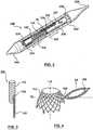
- FIG. 1is a perspective view of a dual valve prosthesis 100 in an expanded, deployed configuration in accordance with an embodiment hereof, with FIG. 2 being a sectional view of a distal portion of a delivery catheter 240 with dual valve prosthesis 100 in a compressed, delivery configuration therein.
- Dual valve prosthesis 100includes a first prosthetic valve section 102 and a second prosthetic valve section 104.
- first prosthetic valve section 102includes a first prosthetic valve 101 for replacing a native aortic valve
- second prosthetic valve section 104includes a second prosthetic valve 107 for replacing a native mitral valve.
- First prosthetic valve section 102includes a self-expanding stent structure 103 for anchoring dual valve prosthesis 100 within a beating heart.
- Stent structure 103 of first prosthetic valve section 102includes a downstream or aortic portion 110 and an upstream or ventricular portion 112, wherein "upstream” and “downstream” are relative to a direction of blood flow when dual valve prosthesis 100 is properly implanted in vivo.
- Each of downstream and upstream portions 110, 112 of stent structure 103is a collapsible, compressible structure made of a material having resiliency or shape memory characteristics in order to return first prosthetic valve section 102 to the deployed configuration shown in FIG. 1 upon release from a delivery device, such as delivery catheter 240.
- downstream and upstream portions 110, 112 of stent structure 103may be initially formed separately and then joined together by any means known to one of ordinary skill in the art such as, for instance, welding, gluing or suturing.
- Stent structure upstream portion 112is a patterned tubular device that defines substantially diamond shaped openings 108, although openings 108 may have any one of a variety of other shapes without departing from the scope hereof.
- Crimping eyelets 124extend from upstream portion 112 at an upstream or inflow end 119 of first prosthetic valve section 102.
- Upstream portion 112has a curved upstream edge defining an arched opening 121 when dual valve prosthesis 100 is in the expanded configuration that allows for the lateral positioning of second prosthetic valve section 104 relative to first prosthetic valve section 102.
- a hinge segment 109 between upstream portion 112 of stent structure 103 and an annular frame 105 of second prosthetic valve section 104extends from an area of an apex of arched opening 121 to laterally extend annular frame 105 therefrom when dual valve prosthesis 100 is in the expanded configuration as discussed in more detail below.
- Stent structure downstream portion 110includes three engagement arms 114 that are generally u-shaped and three prosthetic valve supports 116 to which leaflets of first prosthetic valve 101 are attached. Each engagement arm 114 extends upstream between respective prosthetic valve supports 116 to be positioned between upstream end 119 of first prosthetic valve section 102 and a downstream or outflow end 118 of first prosthetic valve section 102. Upstream ends 122 of engagement arms 114 may be described as being radially spaced or flared from the remainder of stent structure 103 and engagement arms 114 may be described as having a curved profile in the deployed/implanted configuration. When compressed for delivery within a sheath component of delivery catheter 240 as shown in FIG.
- engagement arms 114will somewhat straighten against upstream portion 112 of stent structure 103.
- engagement arms 114will return to their curved configuration with stent structure upstream portion 112 returning to its expanded configuration shown in FIG. 1 .
- engagement arms 114 of downstream portion 110engage the aortic sinuses and upstream portion 112 of stent structure 103 is deployed to seat within the annulus of the native aortic valve and to extend partially into the left ventricle, as discussed in more detail below.
- first prosthetic valve section 102includes prosthetic valve 101 having three valve leaflets to form a tricuspid replacement valve.
- the valve leaflets of prosthetic valve 101are sutured or otherwise securely and sealingly attached to the interior surface of stent structure 103 and/or graft material 111 that encloses or lines stent structure 103 as would be known to one of ordinary skill in the art of prosthetic valve construction.
- Prosthetic valve 101is a one-way valve configured to collapse inwardly, i.e., towards a longitudinal axis LA of first prosthetic valve section 102, during diastole in order to inhibit retrograde blood flow and to open outwardly during systole to allow blood flow through first prosthetic valve section 102.
- prosthetic valve 101may be a bioprosthetic trileaflet heart valve, such as any one of the bioprosthetic trileaflet heart valves being used in implantable heart valve devices currently available that has been adapted for use herein.
- Second prosthetic valve section 104 of dual valve prosthesis 100includes self-expanding annular frame 105 that extends from stent structure 103.
- Annular frame 105forms a circumferential border 113 of a width W that radially extends around the second prosthetic valve 107 to define an apposition surface thereabout.
- width Wmay be in the range of 2.5 mm to 7.5 mm.
- Circumferential border 113has triangular openings defined by the framework thereof, the triangular openings being shown by way of illustration and not limitation.
- circumferential border 113may be covered with a graft material 128, such as any of the materials noted below for graft material 111, to aid in providing a seal against the native anatomy when second prosthetic valve section 104 is deployed within the heart.
- a crimping eyelet 126extends from circumferential border 113 of annular frame 105.
- Annular frame 105has a shape or a profile of a flat washer with a minimal thickness T that provides second prosthetic valve section 104 with a low ventricular profile that does not interfere with the left ventricular outflow tract.
- thickness Tmay be in the range of .025 mm to 0.75 mm.
- Second prosthetic valve 107includes two valve leaflets to form a bicuspid replacement valve.
- the valve leafletsare sutured or otherwise securely and sealingly attached to an inner circumference of annular frame 105 to span a central opening 117 thereof.
- annular frame 105When dual valve prosthesis 100 is in an expanded, deployed configuration, annular frame 105 laterally extends from upstream portion 112 of stent structure 103 such that first and second prosthetic valves 101, 107 are laterally offset from each other.
- annular frame 105is formed with upstream portion 112 of stent structure 103 as a single unit with an integral hinge segment 109 formed to extend therebetween.
- stent structure upstream portion 112 and annular frame 105 with integral hinge segment 109may be formed by etching or otherwise cutting the patterns thereof from a tube, such as a tube 330 of nitinol, as shown in FIG. 3 and then performing a thermal treatment to shape set the structures in the expanded configuration shown in FIG. 4 .
- hinge segment 109When formed in this manner, hinge segment 109 is configured to return annular frame 105 to the shape set expanded configuration of FIG. 4 when dual valve prosthesis 100 is released from a compressed delivery configuration.
- hinge segment 109 and annular frame 105will rotate outwardly and upwardly relative to longitudinal axis LA of stent structure 103 when deployed from delivery catheter 240 within the heart to exert an apposition force AF against any heart structure in which annular frame 105 comes in contact.
- apposition surface provided by circumferential border 113 of annular frame 105exerts an apposition force against a surface of the left ventricle that surrounds the native mitral valve and is intended to seal against perivalvular leakage.
- annular frame 105may be formed separately from upstream portion 112 of stent structure 103 with hinge segment 109 formed to integrally extend from annular frame 105 and then subsequently joined to upstream portion 112 or vice versa.
- second prosthetic valve section 104 in an expanded configurationmay extend along an axis TA that is transverse to longitudinal axis LA of first prosthetic valve section 102, as shown in FIG. 1 , may extend at an obtuse angle to longitudinal axis LA of first prosthetic valve section 102, as shown in FIG. 4 , or may extend at an acute angle to longitudinal axis LA of first prosthetic valve section 102, as shown in FIG. 7 .
- annular frame 105may laterally extend from stent structure 103 at an angle in the range of 45 to 135 degrees with respect to longitudinal axis LA of first prosthetic valve section 102, which is by way of example and not limitation as the actual angle may vary due to anatomical differences in the relative positions of the native valves.
- hinge segment 109 and annular frame 105are configured or formed to rotate outwardly and upwardly relative to longitudinal axis LA of stent structure 103 to exert an apposition force AF against at least the heart structure that surrounds the native heart valve being replaced by second prosthetic valve 107.
- Prosthetic valves 101, 107 secured within the interior of stent structure 103 and annular frame 105, respectively,are configured as one-way valves to allow blood flow in one direction and thereby regulate blood flow there through.
- first prosthetic valve 101includes three valve leaflets to form a tricuspid replacement valve and second prosthetic valve 107 includes two valve leaflets to form a bicuspid replacement valve or other leaflet structure that closes with pressure on the outflow and opens with pressure on the inflow.
- first and second prosthetic valves 101, 107may be tricuspid or bicuspid replacement valves.
- first and second prosthetic valves 101, 107may be a single leaflet replacement valve or a replacement valve with more than three leaflets.
- Natural tissue for forming prosthetic valve leaflets for use in prosthetic valve sections in accordance with embodiments hereofmay be obtained from, for example, heart valves, aortic roots, aortic walls, aortic leaflets, pericardial tissue, such as pericardial patches, bypass grafts, blood vessels, intestinal submucosal tissue, umbilical tissue and the like from humans or animals, such as tissue from bovine, equine or porcine origins.
- Synthetic materials suitable for use as prosthetic valve leaflets in embodiments hereofinclude DACRON® polyester commercially available from Invista North America S.A.R.L. of Wilmington, DE, polyurethane, Gore-Tex or other cloth materials, nylon blends, polymeric materials, and vacuum deposition nitinol fabricated materials.
- One polymeric material from which the replacement valve leaflets can be madeis an ultra-high molecular weight polyethylene material commercially available under the trade designation DYNEEMA from Royal DSM of the Netherlands.
- prosthetic valves 101, 107are sutured or otherwise securely and sealingly attached to an interior surface of stent structure 103 and an inner circumference of annular frame 105 that defines central opening 117, respectively, and/or prosthetic valve 101 may be sutured or otherwise attached to graft material 111 that encloses or lines stent structures 103 as would be known to one of ordinary skill in the art of prosthetic valve construction.
- Graft material 111may be a low-porosity woven fabric, such as polyester, Dacron fabric, or PTFE, which creates a one-way fluid passage when attached to the stent structure 103.
- graft material 111may be a knit or woven polyester, such as a polyester or PTFE knit, which can be utilized when it is desired to provide a medium for tissue ingrowth and the ability for the fabric to stretch to conform to a curved surface.
- Polyester velour fabricsmay alternatively be used, such as when it is desired to provide a medium for tissue ingrowth on one side and a smooth surface on the other side.
- These and other appropriate cardiovascular fabricsare commercially available from Bard Peripheral Vascular, Inc. of Tempe, Ariz., for example.
- graft material 111may also be of a natural material such as pericardium or another membranous tissue such as intestinal submucosa.
- first prosthetic valve section 102is a replacement aortic valve positioned to replace the native aortic valve and second prosthetic valve assembly 104 is a replacement mitral valve positioned to replace the native mitral valve with hinge segment 109 laterally extending therebetween to maintain the relative deployed positions of first and second prosthetic valve sections 102, 104.
- hinge segment 109 and annular frame 105may be deployed to secure the anterior leaflet of the native mitral valve to thereby prevent it from interfering with the operation of the replacement prosthetic aortic and/or mitral valves.
- such methodsmay include advance preparation of the anterior leaflet of the mitral valve in order for subsequent deployment of dual valve prosthesis 100 to function to "catch' or secure the anterior leaflet in the open position and to avoid the mitral chordae.
- FIGS. 5-7illustrate a method of performing a concurrent transcatheter valve replacement of the aortic valve and mitral valve of a beating heart in accordance with an embodiment hereof.
- delivery catheter 240includes a distal tip 244 with a distal sheath section 243 that is attached to an inner shaft component 234, which extends within distal sheath section 243 and a proximal sheath section 242 to a proximal end (not shown) of delivery catheter 240 to be assessable by a clinician.
- Proximal and distal sheath sections 242, 243may be collectively referred to herein as a sheath component that is attached at a proximal end thereof to an outer shaft component 236 that extends to the proximal end of delivery catheter 240 to be assessable by the clinician.
- distal tip 244 with distal sheath section 243are configured to be releasably coupled to a distal end of proximal sheath section 242 at parting line PL.
- Dual valve prosthesis 100is compressed in a delivery configuration within the sheath component with first and second prosthetic valve sections 102, 104 being sequentially loaded therein such that engagement arms 114 of stent structure downstream portion 110 of self-expanding stent structure 103 are held in a compressed state primarily by distal sheath section 243 and stent structure upstream portion 112 and annular frame 105 are held in a compressed state primarily by proximal sheath section 242.
- a cylindrical rebated retainer 246is sized to be slidably received within the sheath component and includes a tubular shaft component 248 that slidably extends between inner and outer shaft components 234, 236 to the proximal end of delivery catheter 240 to be assessable to the clinician.
- Rebated retainer 246includes a cutout 245 configured to accommodate second prosthetic valve section 104 in a collapsed, compressed state and a plurality of eyelet-shaped recesses 247 for receiving crimping eyelets 124, 126 of stent structure 103 and annular frame 105, respectively.
- Delivery catheter 240is shown in FIGS. 5-7 having been introduced into the left ventricle LV via a transapical minimally invasive procedure.
- delivery catheter 240 so positionedmay have been tracked through a trocar or other introducer device (not shown) that has been inserted through purse-string sutures (not shown) previously placed in the left ventricular apex.
- the purse-string sutureswould be tightened around the trocar or other introducer device and a hemostasis valve would also be used to minimize blood leakage from the heart during the percutaneous replacement valve implantation procedure, as would be understood by one of ordinary skill in the art.
- the proximal ends (not shown) of delivery catheter 240 and its componentsextend out of the body to be accessible by a clinician.
- Delivery catheter 240is shown in FIG. 5 positioned through the native aortic valve AV such that distal tip 244 and distal sheath section 243 extend into the aorta A while proximal sheath section 242 is positioned to extend through the native aortic valve AV.
- parting line PL between proximal and distal sheath sections 242, 243is preferably positioned distal of the leaflets of the native aortic valve in line with the aortic sinuses.
- distal tip 244 with distal sheath section 243are distally advanced into the aorta relative to the remainder of delivery catheter 240 to release engagement arms 114 of stent structure 103 such that engagement arms 114 implant within the aortic sinuses.
- delivery catheter 240may be proximally retracted concurrent with the release of engagement arms 114, as shown in FIG. 6 , to assure engagement arms 114 engage the aortic sinuses when deployed.
- proximal retraction of sheath component 240 relative to the remainder of delivery catheter 240sequentially releases upstream portion 112 of stent structure 103 and then annular frame 105 to complete the deployment of dual valve prosthesis 100. More particularly when the proximal retraction of sheath component 240 uncovers a distal end 747 of rebated retainer 246, crimping eyelets 124 on upstream end 119 of first prosthetic valve section 102 are freed from from corresponding recesses 247 in rebated retainer distal end 747 to thereby allow stent structure upstream portion 112 to return to its expanded configuration. In this manner, stent structure upstream portion 112 is implanted within the annulus of the native aortic valve and a portion of the left ventricle that surrounds the native aortic valve.
- sheath component 240uncovers crimping eyelet 126 on annular frame 105 to free eyelet 126 from its corresponding recess 247 in rebated retainer 246 and thereby releases annular frame 105 to return to its expanded configuration.
- the release of annular frame 105 from sheath component 242permits annular frame 105 to rotate outwardly from stent structure 103 at hinge segment 109 until annular frame 105 is in apposition with a surface of the left ventricle that surrounds the native mitral valve.
- annular frame 105 of the second prosthetic heart valve section 104exerts an apposition force that acts against the heart structure that surrounds the native mitral valve when deployed to implant second prosthetic valve section 104 against the native mitral valve and left ventricle.
- deployment of stent structure upstream portion 112 and annular frame 105is controlled by the clinician to occur when the heart is in diastole such that the anterior leaflet of the native mitral valve is captured and held against the ventricle wall by one or more of stent structure upstream portion 112, hinge segment 109 and annular frame 105 with the posterior leaflet of the native mitral valve being captured and held toward or against the ventricle wall by annular frame 105.
- FIG. 7depicts dual valve prosthesis 100 implanted within the heart with first prosthetic valve section 102 implanted to replace the native aortic valve and second prosthetic valve section 104 implanted to replace the native mitral valve.
- prosthetic mitral valve 107is a one-way bicuspid valve that is configured to be positioned in the heart within the left ventricle to permit blood flow through prosthetic mitral valve 107 in the direction of arrows BF during atrial emptying and ventricular filling when the leaflets of prosthetic mitral valve 107 open or part to allow blood to flow into the left ventricle.
- Prosthetic aortic valve 101is a one-way tricuspid valve that is configured to be positioned in the heart between the left ventricle and the aorta within the annulus of the native aortic valve to permit blood flow through inflow end 119 of first prosthetic valve section 102 in the direction of arrows BF during systole when the leaflets of prosthetic aortic valve 101 open or part to allow blood to flow into the aorta.
- each of prosthetic mitral valve 107 and prosthetic aortic valve 101may be a bioprosthetic heart valve such as any one of the bioprosthetic heart valves being used in implantable heart valve devices currently available that has been adapted for use herein.
- stent structure of FIG. 1is merely an exemplary stent structure and various other forms for stent structures that are suitable to anchor a replacement aortic valve within the native aortic valve may be adapted for use in embodiments hereof.
- stent structure 103 of first prosthetic valve section 102may a patterned tubular device with a stepped outer diameter such that an aortic portion of the stent structure has an expanded diameter that is greater than an expanded diameter of a ventricular portion of the stent structure.
- aortic portion of the stent structurewould be sized to be expandable within the aortic sinuses for securing first prosthetic valve section 102 with respect to the native aortic valve without the use of engagement arms 114.
- various methods of fabricationcan be used in accordance with embodiments hereof to manufacture self-expanding stent structure 103 and annular frame 105 as either an integral unitary structure, such as by laser cutting or chemical etching the patterns thereof in a flat sheet or a tube, or a plurality of individual structures that are joined, such as by one of welding, soldering, or the like, without departing from the scope of the present invention.
- stent structure 103 and annular frame 105may be made balloon-expandable or one may be self-expandable with the other balloon-expandable.
Landscapes
- Health & Medical Sciences (AREA)
- Cardiology (AREA)
- Engineering & Computer Science (AREA)
- Biomedical Technology (AREA)
- Heart & Thoracic Surgery (AREA)
- Transplantation (AREA)
- Oral & Maxillofacial Surgery (AREA)
- Vascular Medicine (AREA)
- Life Sciences & Earth Sciences (AREA)
- Animal Behavior & Ethology (AREA)
- General Health & Medical Sciences (AREA)
- Public Health (AREA)
- Veterinary Medicine (AREA)
- Prostheses (AREA)
Abstract
Description
- The invention relates generally to a prosthetic valve for replacing a native valve or a previously implanted prosthetic valve in a non-surgical interventional procedure. More particularly, the invention relates to a dual valve prosthesis having a prosthetic aortic valve combined with a prosthetic mitral valve for concurrently replacing the corresponding native valves or previously implanted prosthetic valves in a non-surgical interventional procedure.
- A wide range of medical treatments are known that utilize "endoluminal prostheses." As used herein, endoluminal prostheses are intended to mean medical devices that are adapted for temporary or permanent implantation within a body lumen, including both naturally occurring and artificially made lumens. Examples of lumens in which endoluminal prostheses may be implanted include, without limitation: arteries, veins, gastrointestinal tract, biliary tract, urethra, trachea, hepatic and cerebral shunts, and fallopian tubes.
- Stent prostheses are known for implantation within a body lumen for providing artificial radial support to the wall tissue that defines the body lumen. To provide radial support to a blood vessel, such as one that has been widened by a percutaneous transluminal coronary angioplasty, commonly referred to as "angioplasty," "PTA" or "PTCA", a stent may be implanted in conjunction with the procedure. Under this procedure, the stent may be collapsed to an insertion diameter and inserted into the vasculature at a site remote from the diseased vessel. The stent may then be delivered to the desired treatment site within the affected vessel and deployed, by self-expansion or radial expansion, to its desired diameter for treatment.
- Recently, flexible prosthetic valves supported by stent structures that can be delivered percutaneously using a catheter-based delivery system have been developed for heart and venous valve replacement. These prosthetic valves may include either self-expanding or balloon-expandable stent structures with valve leaflets disposed within the interior of the stent structure. The prosthetic valve can be reduced in diameter, by being contained within a sheath component of a delivery catheter or by crimping onto a balloon catheter, and advanced through the venous or arterial vasculature. Once the prosthetic valve is positioned at the treatment site, for instance within an incompetent native or previously implanted prosthetic valve, the stent structure may be expanded to hold the prosthetic valve firmly in place. One embodiment of a prosthetic valve having a stent structure is disclosed in
U.S. Pat. No. 5,957,949 to Leonhardt et al. entitled "Percutaneous Placement Valve Stent", which is incorporated by reference herein in its entirety. - Valvular heart disease is any disease process involving one or more of the valves of the heart,i.e., the aortic and mitral valves on the left and the pulmonary and tricuspid valves on the right. Severe valve damage may be treated with a valve replacement, with aortic valves and severely damaged mitral valves being the most often replaced heart valves. Some patients present with more than one heart valve being damaged so that the patient may need a dual valve replacement requiring more than one heart valve to be repaired or replaced. Whereas the use of minimally invasive techniques may be preferred, such an approach may be difficult in a dual valve replacement as placement of the prosthetic mitral valve prior to or subsequent of placement of the prosthetic aortic valve may be extremely difficult due to the relative locations of the two native valves, the lack of space in the left ventricle, and/or the concern of having to cross the first deployed prosthetic valve with the second delivery system and prosthetic valve under certain circumstances. Moreover, when a prosthetic valve is percutaneously delivered to replace a stenotic or insufficient aortic or mitral valve, a fundamental concern is that the prosthesis be deployed as precisely as possible so as to assure proper functioning, to avoid paravalvular leakage and to minimize any negative impact on the adjacent heart valve, each of which becomes more difficult to achieve with a dual valve replacement performed using multiple prosthetic valves and delivery devices. Further, sufficient prosthetic mitral valve fixation against high systolic pressures is also particularly important as migration or movement of the mitral valve prosthetic device can potentially block the left ventricular outflow tract or inhibit native or replacement aortic valve function. As such patients who must have a dual valve replacement most often undergo open heart surgical replacement procedures to implant the prosthetic aortic and mitral valves or one of the valves goes untreated. Accordingly a need exists in the art for apparatus and methods that allow a clinician to perform a dual heart valve replacement in a minimally invasive manner.
- Embodiments hereof are directed to a dual valve prosthesis having first and second prosthetic valve sections. The first prosthetic valve section includes a stent structure with a first prosthetic valve secured therein and the second prosthetic valve section includes an annular frame with a second prosthetic valve secured therein, wherein the annular frame extends from the stent structure such that the first and second prosthetic valves are laterally offset from each other when the dual valve prosthesis is in an expanded configuration. In an embodiment, the annular frame forms a border that radially extends around the second prosthetic valve to define an apposition surface and has a profile of a flat washer. In a method in accordance herewith, the first and second prosthetic valve sections include prosthetic aortic and mitral valves, respectively, and the dual heart valve prosthesis is configured to replace both the native aortic and mitral valves of the heart in a single transcatheter heart valve implantation procedure.
- The foregoing and other features and advantages of the invention will be apparent from the following description of embodiments thereof as illustrated in the accompanying drawings. The accompanying drawings, which are incorporated herein and form a part of the specification, further serve to explain the principles of the invention and to enable a person skilled in the pertinent art to make and use the invention. The drawings are not to scale.
FIG. 1 is a perspective view of a dual valve prosthesis in an expanded configuration in accordance with an embodiment hereof.FIG. 2 is a sectional view of a distal portion of a delivery catheter with the dual valve prosthesis ofFIG. 1 in a compressed delivery configuration therein.FIGS. 3 and 4 illustrate a method of fabricating a stent structure and an annular frame of the dual valve prosthesis ofFIG. 1 in accordance with an embodiment hereof.FIGS. 5-7 illustrate a method of performing a concurrent transcatheter valve replacement of the native aortic and mitral valves of a beating heart in accordance with an embodiment hereof.- The following detailed description is merely exemplary in nature and is not intended to limit the invention or the application and uses of the invention. Although the description of embodiments hereof is in the context of concurrent aortic and mitral heart valve replacement, the invention may be adapted to be used for other concurrent valve replacement where it is deemed useful. Furthermore, there is no intention to be bound by any expressed or implied theory presented in the preceding technical field, background, brief summary or the following detailed description.
- Specific embodiments of the present invention are now described with reference to the figures, wherein like reference numbers indicate identical or functionally similar elements. The terms "distal" and "proximal" are used in the following description with respect to a position or direction relative to the treating clinician. "Distal" or "distally" are a position distant from or in a direction away from the clinician. "Proximal" and "proximally" are a position near or in a direction toward the clinician. Further the term "self-expanding" is used in the following description with reference to the stent structure and annular frame of the dual valve prosthesis and is intended to convey that the stent structure and annular frame are shaped or formed from a material that has a mechanical memory to return to an expanded deployed configuration from a compressed or constricted delivery configuration. Non-exhaustive exemplary materials that may be rendered self-expanding include stainless steel, a pseudo-elastic metal such as a nickel titanium alloy or nitinol, various polymers, and a so-called super alloy, which may have a base metal of nickel, cobalt, chromium, or other metal. Mechanical memory may be imparted to a wire or tubular structure used to form the stent structure and/or annular frame by thermal treatment to achieve a spring temper in stainless steel, for example, or to set a shape memory in a susceptible metal alloy, such as nitinol. Various polymers that can be made to have shape memory characteristics may also be suitable for use in embodiments hereof to include polymers such as polynorborene, transpolyisoprene, styrene-butadiene, and polyurethane. As well poly L-D lactic copolymer, oligo caprylactone copolymer and poly cyclo-octine can be used separately or in conjunction with other shape memory polymers.
- Embodiments hereof are related to a dual valve prosthesis configured for deployment within the mitral and aortic valves of the heart in a single transcatheter heart valve implantation procedure.
FIG. 1 is a perspective view of adual valve prosthesis 100 in an expanded, deployed configuration in accordance with an embodiment hereof, withFIG. 2 being a sectional view of a distal portion of adelivery catheter 240 withdual valve prosthesis 100 in a compressed, delivery configuration therein.Dual valve prosthesis 100 includes a firstprosthetic valve section 102 and a secondprosthetic valve section 104. In an embodiment hereof, firstprosthetic valve section 102 includes a firstprosthetic valve 101 for replacing a native aortic valve and secondprosthetic valve section 104 includes a secondprosthetic valve 107 for replacing a native mitral valve. - First
prosthetic valve section 102 includes a self-expandingstent structure 103 for anchoringdual valve prosthesis 100 within a beating heart.Stent structure 103 of firstprosthetic valve section 102 includes a downstream oraortic portion 110 and an upstream orventricular portion 112, wherein "upstream" and "downstream" are relative to a direction of blood flow whendual valve prosthesis 100 is properly implanted in vivo. Each of downstream andupstream portions stent structure 103 is a collapsible, compressible structure made of a material having resiliency or shape memory characteristics in order to return firstprosthetic valve section 102 to the deployed configuration shown inFIG. 1 upon release from a delivery device, such asdelivery catheter 240. In an embodiment, downstream andupstream portions stent structure 103 may be initially formed separately and then joined together by any means known to one of ordinary skill in the art such as, for instance, welding, gluing or suturing. - Stent structure
upstream portion 112 is a patterned tubular device that defines substantially diamond shapedopenings 108, althoughopenings 108 may have any one of a variety of other shapes without departing from the scope hereof. Crimpingeyelets 124 extend fromupstream portion 112 at an upstream orinflow end 119 of firstprosthetic valve section 102.Upstream portion 112 has a curved upstream edge defining anarched opening 121 whendual valve prosthesis 100 is in the expanded configuration that allows for the lateral positioning of secondprosthetic valve section 104 relative to firstprosthetic valve section 102. More particularly, ahinge segment 109 betweenupstream portion 112 ofstent structure 103 and anannular frame 105 of secondprosthetic valve section 104 extends from an area of an apex ofarched opening 121 to laterally extendannular frame 105 therefrom whendual valve prosthesis 100 is in the expanded configuration as discussed in more detail below. - Stent structure
downstream portion 110 includes threeengagement arms 114 that are generally u-shaped and three prosthetic valve supports 116 to which leaflets of firstprosthetic valve 101 are attached. Eachengagement arm 114 extends upstream between respective prosthetic valve supports 116 to be positioned betweenupstream end 119 of firstprosthetic valve section 102 and a downstream oroutflow end 118 of firstprosthetic valve section 102. Upstream ends 122 ofengagement arms 114 may be described as being radially spaced or flared from the remainder ofstent structure 103 andengagement arms 114 may be described as having a curved profile in the deployed/implanted configuration. When compressed for delivery within a sheath component ofdelivery catheter 240 as shown inFIG. 2 ,engagement arms 114 will somewhat straighten againstupstream portion 112 ofstent structure 103. Whenstent structure 103 is released from the sheath component,engagement arms 114 will return to their curved configuration with stent structureupstream portion 112 returning to its expanded configuration shown inFIG. 1 . In an embodiment when firstprosthetic valve section 102 is deployed to replace a native aortic valve,engagement arms 114 ofdownstream portion 110 engage the aortic sinuses andupstream portion 112 ofstent structure 103 is deployed to seat within the annulus of the native aortic valve and to extend partially into the left ventricle, as discussed in more detail below. - In addition to
stent structure 103, firstprosthetic valve section 102 includesprosthetic valve 101 having three valve leaflets to form a tricuspid replacement valve. The valve leaflets ofprosthetic valve 101 are sutured or otherwise securely and sealingly attached to the interior surface ofstent structure 103 and/orgraft material 111 that encloses orlines stent structure 103 as would be known to one of ordinary skill in the art of prosthetic valve construction.Prosthetic valve 101 is a one-way valve configured to collapse inwardly,i.e., towards a longitudinal axis LA of firstprosthetic valve section 102, during diastole in order to inhibit retrograde blood flow and to open outwardly during systole to allow blood flow through firstprosthetic valve section 102. In embodiments hereof,prosthetic valve 101 may be a bioprosthetic trileaflet heart valve, such as any one of the bioprosthetic trileaflet heart valves being used in implantable heart valve devices currently available that has been adapted for use herein. - Second
prosthetic valve section 104 ofdual valve prosthesis 100 includes self-expandingannular frame 105 that extends fromstent structure 103.Annular frame 105 forms acircumferential border 113 of a width W that radially extends around the secondprosthetic valve 107 to define an apposition surface thereabout. In an embodiment, width W may be in the range of 2.5 mm to 7.5 mm.Circumferential border 113 has triangular openings defined by the framework thereof, the triangular openings being shown by way of illustration and not limitation. One or both sides ofcircumferential border 113 may be covered with agraft material 128, such as any of the materials noted below forgraft material 111, to aid in providing a seal against the native anatomy when secondprosthetic valve section 104 is deployed within the heart. A crimpingeyelet 126 extends fromcircumferential border 113 ofannular frame 105.Annular frame 105 has a shape or a profile of a flat washer with a minimal thickness T that provides secondprosthetic valve section 104 with a low ventricular profile that does not interfere with the left ventricular outflow tract. In an embodiment, thickness T may be in the range of .025 mm to 0.75 mm.Annular frame 105 so described aids in maintaining apposition of secondprosthetic valve section 104 against then native anatomy to provide a seal there against. Secondprosthetic valve 107 includes two valve leaflets to form a bicuspid replacement valve. The valve leaflets are sutured or otherwise securely and sealingly attached to an inner circumference ofannular frame 105 to span acentral opening 117 thereof. - When
dual valve prosthesis 100 is in an expanded, deployed configuration,annular frame 105 laterally extends fromupstream portion 112 ofstent structure 103 such that first and secondprosthetic valves annular frame 105 is formed withupstream portion 112 ofstent structure 103 as a single unit with anintegral hinge segment 109 formed to extend therebetween. In such an embodiment, stent structureupstream portion 112 andannular frame 105 withintegral hinge segment 109 may be formed by etching or otherwise cutting the patterns thereof from a tube, such as atube 330 of nitinol, as shown inFIG. 3 and then performing a thermal treatment to shape set the structures in the expanded configuration shown inFIG. 4 . When formed in this manner,hinge segment 109 is configured to returnannular frame 105 to the shape set expanded configuration ofFIG. 4 whendual valve prosthesis 100 is released from a compressed delivery configuration. In an embodiment,hinge segment 109 andannular frame 105 will rotate outwardly and upwardly relative to longitudinal axis LA ofstent structure 103 when deployed fromdelivery catheter 240 within the heart to exert an apposition force AF against any heart structure in whichannular frame 105 comes in contact. More particularly, whendual valve prosthesis 100 is deployed within the heart such that secondprosthetic valve 107 secured withinannular frame 105 is utilized as a replacement mitral valve, the apposition surface provided bycircumferential border 113 ofannular frame 105 exerts an apposition force against a surface of the left ventricle that surrounds the native mitral valve and is intended to seal against perivalvular leakage. - In another embodiment,
annular frame 105 may be formed separately fromupstream portion 112 ofstent structure 103 withhinge segment 109 formed to integrally extend fromannular frame 105 and then subsequently joined toupstream portion 112 or vice versa. - Depending on the anatomy of the heart in which
dual valve prosthesis 100 is to be implanted and particularly in view of the anatomical position of the native aortic valve relative to the native mitral valve, in embodiments hereof secondprosthetic valve section 104 in an expanded configuration may extend along an axis TA that is transverse to longitudinal axis LA of firstprosthetic valve section 102, as shown inFIG. 1 , may extend at an obtuse angle to longitudinal axis LA of firstprosthetic valve section 102, as shown inFIG. 4 , or may extend at an acute angle to longitudinal axis LA of firstprosthetic valve section 102, as shown inFIG. 7 . Accordingly in the expanded configurationannular frame 105 may laterally extend fromstent structure 103 at an angle in the range of 45 to 135 degrees with respect to longitudinal axis LA of firstprosthetic valve section 102, which is by way of example and not limitation as the actual angle may vary due to anatomical differences in the relative positions of the native valves. In each of the aforementioned expanded configurations when deployed within the heart,hinge segment 109 andannular frame 105 are configured or formed to rotate outwardly and upwardly relative to longitudinal axis LA ofstent structure 103 to exert an apposition force AF against at least the heart structure that surrounds the native heart valve being replaced by secondprosthetic valve 107. Prosthetic valves stent structure 103 andannular frame 105, respectively, are configured as one-way valves to allow blood flow in one direction and thereby regulate blood flow there through. In the embodiment shown and described with reference toFIG. 1 , firstprosthetic valve 101 includes three valve leaflets to form a tricuspid replacement valve and secondprosthetic valve 107 includes two valve leaflets to form a bicuspid replacement valve or other leaflet structure that closes with pressure on the outflow and opens with pressure on the inflow. In other embodiments in accordance herewith, one or both of first and secondprosthetic valves prosthetic valves - The valve leaflets of
prosthetic valves stent structure 103 and an inner circumference ofannular frame 105 that definescentral opening 117, respectively, and/orprosthetic valve 101 may be sutured or otherwise attached to graft material 111 that encloses orlines stent structures 103 as would be known to one of ordinary skill in the art of prosthetic valve construction.Graft material 111 may be a low-porosity woven fabric, such as polyester, Dacron fabric, or PTFE, which creates a one-way fluid passage when attached to thestent structure 103. In an embodiment,graft material 111 may be a knit or woven polyester, such as a polyester or PTFE knit, which can be utilized when it is desired to provide a medium for tissue ingrowth and the ability for the fabric to stretch to conform to a curved surface. Polyester velour fabrics may alternatively be used, such as when it is desired to provide a medium for tissue ingrowth on one side and a smooth surface on the other side. These and other appropriate cardiovascular fabrics are commercially available from Bard Peripheral Vascular, Inc. of Tempe, Ariz., for example. In another embodiment,graft material 111 may also be of a natural material such as pericardium or another membranous tissue such as intestinal submucosa. - The general direction of blood flow through
dual valve prosthesis 100 when deployedin vivo is depicted by arrows BF inFIG. 1 . In an embodiment in whichdual valve prosthesis 100 is deployed within the heart, as described in more detail below, firstprosthetic valve section 102 is a replacement aortic valve positioned to replace the native aortic valve and secondprosthetic valve assembly 104 is a replacement mitral valve positioned to replace the native mitral valve withhinge segment 109 laterally extending therebetween to maintain the relative deployed positions of first and secondprosthetic valve sections dual valve prosthesis 100, one or both ofhinge segment 109 andannular frame 105 may be deployed to secure the anterior leaflet of the native mitral valve to thereby prevent it from interfering with the operation of the replacement prosthetic aortic and/or mitral valves. In an embodiment, such methods may include advance preparation of the anterior leaflet of the mitral valve in order for subsequent deployment ofdual valve prosthesis 100 to function to "catch' or secure the anterior leaflet in the open position and to avoid the mitral chordae. FIGS. 5-7 illustrate a method of performing a concurrent transcatheter valve replacement of the aortic valve and mitral valve of a beating heart in accordance with an embodiment hereof. Initially with reference toFIG. 2 ,delivery catheter 240 includes adistal tip 244 with adistal sheath section 243 that is attached to aninner shaft component 234, which extends withindistal sheath section 243 and aproximal sheath section 242 to a proximal end (not shown) ofdelivery catheter 240 to be assessable by a clinician. Proximal anddistal sheath sections outer shaft component 236 that extends to the proximal end ofdelivery catheter 240 to be assessable by the clinician. In an embodiment hereof,distal tip 244 withdistal sheath section 243 are configured to be releasably coupled to a distal end ofproximal sheath section 242 at parting line PL.Dual valve prosthesis 100 is compressed in a delivery configuration within the sheath component with first and secondprosthetic valve sections engagement arms 114 of stent structuredownstream portion 110 of self-expandingstent structure 103 are held in a compressed state primarily bydistal sheath section 243 and stent structureupstream portion 112 andannular frame 105 are held in a compressed state primarily byproximal sheath section 242.- In the embodiment shown in
FIG. 2 , a cylindrical rebatedretainer 246 is sized to be slidably received within the sheath component and includes atubular shaft component 248 that slidably extends between inner andouter shaft components delivery catheter 240 to be assessable to the clinician.Rebated retainer 246 includes acutout 245 configured to accommodate secondprosthetic valve section 104 in a collapsed, compressed state and a plurality of eyelet-shapedrecesses 247 for receiving crimpingeyelets stent structure 103 andannular frame 105, respectively. Delivery catheter 240 is shown inFIGS. 5-7 having been introduced into the left ventricle LV via a transapical minimally invasive procedure. In an embodiment,delivery catheter 240 so positioned may have been tracked through a trocar or other introducer device (not shown) that has been inserted through purse-string sutures (not shown) previously placed in the left ventricular apex. The purse-string sutures would be tightened around the trocar or other introducer device and a hemostasis valve would also be used to minimize blood leakage from the heart during the percutaneous replacement valve implantation procedure, as would be understood by one of ordinary skill in the art. As previously noted, the proximal ends (not shown) ofdelivery catheter 240 and its components extend out of the body to be accessible by a clinician.Delivery catheter 240 is shown inFIG. 5 positioned through the native aortic valve AV such thatdistal tip 244 anddistal sheath section 243 extend into the aorta A whileproximal sheath section 242 is positioned to extend through the native aortic valve AV. In an embodiment, parting line PL between proximal anddistal sheath sections FIG. 6 ,distal tip 244 withdistal sheath section 243 are distally advanced into the aorta relative to the remainder ofdelivery catheter 240 to releaseengagement arms 114 ofstent structure 103 such thatengagement arms 114 implant within the aortic sinuses. In an embodiment,delivery catheter 240 may be proximally retracted concurrent with the release ofengagement arms 114, as shown inFIG. 6 , to assureengagement arms 114 engage the aortic sinuses when deployed.- With reference to
FIG. 7 , proximal retraction ofsheath component 240 relative to the remainder ofdelivery catheter 240 sequentially releasesupstream portion 112 ofstent structure 103 and thenannular frame 105 to complete the deployment ofdual valve prosthesis 100. More particularly when the proximal retraction ofsheath component 240 uncovers adistal end 747 of rebatedretainer 246, crimpingeyelets 124 onupstream end 119 of firstprosthetic valve section 102 are freed from from correspondingrecesses 247 in rebated retainerdistal end 747 to thereby allow stent structureupstream portion 112 to return to its expanded configuration. In this manner, stent structureupstream portion 112 is implanted within the annulus of the native aortic valve and a portion of the left ventricle that surrounds the native aortic valve. - Continued proximal retraction of
sheath component 240 uncovers crimpingeyelet 126 onannular frame 105 tofree eyelet 126 from itscorresponding recess 247 in rebatedretainer 246 and thereby releasesannular frame 105 to return to its expanded configuration. The release ofannular frame 105 fromsheath component 242 permitsannular frame 105 to rotate outwardly fromstent structure 103 athinge segment 109 untilannular frame 105 is in apposition with a surface of the left ventricle that surrounds the native mitral valve. In this manner, the apposition surface ofannular frame 105 of the second prostheticheart valve section 104 exerts an apposition force that acts against the heart structure that surrounds the native mitral valve when deployed to implant secondprosthetic valve section 104 against the native mitral valve and left ventricle. After implantation ofdual valve prosthesis 100,delivery catheter 240 and its components are removed from the heart with the purse-string sutures noted above being tightened thereafter to close the opening in the left ventricular apex. - In an embodiment, deployment of stent structure
upstream portion 112 andannular frame 105 is controlled by the clinician to occur when the heart is in diastole such that the anterior leaflet of the native mitral valve is captured and held against the ventricle wall by one or more of stent structureupstream portion 112,hinge segment 109 andannular frame 105 with the posterior leaflet of the native mitral valve being captured and held toward or against the ventricle wall byannular frame 105. FIG. 7 depictsdual valve prosthesis 100 implanted within the heart with firstprosthetic valve section 102 implanted to replace the native aortic valve and secondprosthetic valve section 104 implanted to replace the native mitral valve. With a comparison ofFIG. 1 andFIG. 7 , prostheticmitral valve 107 is a one-way bicuspid valve that is configured to be positioned in the heart within the left ventricle to permit blood flow through prostheticmitral valve 107 in the direction of arrows BF during atrial emptying and ventricular filling when the leaflets of prostheticmitral valve 107 open or part to allow blood to flow into the left ventricle. Prostheticaortic valve 101 is a one-way tricuspid valve that is configured to be positioned in the heart between the left ventricle and the aorta within the annulus of the native aortic valve to permit blood flow throughinflow end 119 of firstprosthetic valve section 102 in the direction of arrows BF during systole when the leaflets of prostheticaortic valve 101 open or part to allow blood to flow into the aorta. In embodiments hereof, each of prostheticmitral valve 107 and prostheticaortic valve 101 may be a bioprosthetic heart valve such as any one of the bioprosthetic heart valves being used in implantable heart valve devices currently available that has been adapted for use herein.- It will be appreciated by one of ordinary skill in the art that the stent structure of
FIG. 1 is merely an exemplary stent structure and various other forms for stent structures that are suitable to anchor a replacement aortic valve within the native aortic valve may be adapted for use in embodiments hereof. For instance in one embodiment,stent structure 103 of firstprosthetic valve section 102 may a patterned tubular device with a stepped outer diameter such that an aortic portion of the stent structure has an expanded diameter that is greater than an expanded diameter of a ventricular portion of the stent structure. The aortic portion of the stent structure would be sized to be expandable within the aortic sinuses for securing firstprosthetic valve section 102 with respect to the native aortic valve without the use ofengagement arms 114. Further as would be appreciated by one of ordinary skill in the art, various methods of fabrication can be used in accordance with embodiments hereof to manufacture self-expandingstent structure 103 andannular frame 105 as either an integral unitary structure, such as by laser cutting or chemical etching the patterns thereof in a flat sheet or a tube, or a plurality of individual structures that are joined, such as by one of welding, soldering, or the like, without departing from the scope of the present invention. Further in other embodiments in accordance herewith,stent structure 103 andannular frame 105 may be made balloon-expandable or one may be self-expandable with the other balloon-expandable. - While various embodiments have been described above, it should be understood that they have been presented only as illustrations and examples of the present invention, and not by way of limitation. It will be apparent to persons skilled in the relevant art that various changes in form and detail can be made therein without departing from the spirit and scope of the invention. Thus, the breadth and scope of the present invention should not be limited by any of the above-described exemplary embodiments, but should be defined only in accordance with the appended claims and their equivalents. It will also be understood that each feature of each embodiment discussed herein, and of each reference cited herein, can be used in combination with the features of any other embodiment. All patents and publications discussed herein are incorporated by reference herein in their entirety.
- It follows a list of embodiments:
- 1. A dual valve prosthesis comprising:
- a first prosthetic valve section having a stent structure with a first prosthetic valve secured therein; and
- a second prosthetic valve section having an annular frame with a second prosthetic valve secured therein, wherein when the dual valve prosthesis is in an expanded configuration the annular frame laterally extends from the stent structure such that the first and second prosthetic valves are laterally offset from each other.
- 2. The dual valve prosthesis of embodiment 1, wherein the annular frame forms a border that radially extends around the second prosthetic valve to define an apposition surface.
- 3. The dual valve prosthesis of embodiment 1, wherein the annular frame has a profile of a flat washer.
- 4. The dual valve prosthesis of embodiment 1, wherein a hinge segment laterally extends between the annular frame and the stent structure when the dual valve prosthesis is in the expanded configuration.
- 5. The dual valve prosthesis of embodiment 4, wherein the hinge segment and the annular frame extend from an arched opening defined by an upstream edge of the stent structure.
- 6. The dual valve prosthesis of
embodiment 5, wherein at least an upstream portion of the stent structure, annular frame and hinge segment are an integral self-expanding structure with a shape set to return to the expanded configuration from a compressed delivery configuration. - 7. The dual valve prosthesis of embodiment 6, wherein a downstream portion of the stent structure includes a plurality of engagement arms each having an upstream end that is radially spaced from the upstream portion of the stent structure.
- 8. The dual valve prosthesis of embodiment 1, wherein the first prosthetic valve is a trileaflet prosthetic aortic valve.
- 9. The dual valve prosthesis of embodiment 8, wherein the second prosthetic valve is a bicuspid prosthetic mitral valve.
- 10. The dual valve prosthesis of embodiment 1, wherein in the expanded configuration the annular frame laterally extends from the stent structure at an angle in the range of 45 to 135 degrees with respect to a longitudinal axis of the first prosthetic valve section.
- 11. A method of implanting a dual valve prosthesis within a beating heart comprising:
- introducing a delivery catheter transapically into the left ventricle of the heart, wherein a dual heart valve prosthesis disposed within a distal portion of the delivery catheter includes a first prosthetic heart valve section having a stent structure with a first prosthetic valve secured therein and a second prosthetic heart valve section having an annular frame with a second prosthetic valve secured therein, wherein the annular frame laterally extends from the stent structure when the dual valve prosthesis is implanted in the heart;
- deploying the first prosthetic heart valve section to implant within the native aortic valve such that the first prosthetic valve is a replacement aortic valve; and
- deploying the second prosthetic heart valve section to implant against the native mitral valve such that the second prosthetic valve is a replacement mitral valve, wherein the annular frame of the second prosthetic heart valve section exerts an apposition force that acts against the heart structure that surrounds the native mitral valve when deployed.
- 12. The method of embodiment 11, wherein the stent structure and the annular frame are self-expanding and wherein the delivery catheter includes a sheath component such that during the step of introducing the delivery catheter the stent structure and annular frame are compressed in a delivery configuration within the distal portion of the delivery catheter by the sheath component.
- 13. The method of embodiment 12, wherein a hinge segment extends between the annular frame and the stent structure and wherein the step of deploying the second prosthetic heart valve section includes releasing the hinge segment and annular frame from the sheath component to permit the annular frame to rotate outwardly from the stent structure at the hinge segment.
- 14. The method of embodiment 12, wherein the step of deploying the first prosthetic heart valve section includes positioning the stent structure thereof within the native aortic valve and releasing engagement arms of the stent structure from the sheath component such that the engagement arms implant within the aortic sinuses.
- 15. The method of embodiment 14, wherein the step of deploying the first prosthetic heart valve section includes releasing an upstream portion of the stent structure from the sheath component to implant the upstream portion within the annulus of the native aortic valve.
- 16. The method of embodiment 15, wherein the step of deploying the second prosthetic heart valve section includes releasing the annular frame from the sheath component into apposition with a surface of the left ventricle that surrounds the native mitral valve.
- 17. The method of embodiment 16, wherein releasing the engagement arms and upstream portion of the stent structure of the first prosthetic heart valve section occurs before releasing the annular frame of the second prosthetic heart valve section.
- 18. The method of embodiment 11, wherein the delivery catheter includes a rebated retainer within a sheath component thereof that is used to secure crimping eyelets of the stent structure and the annular frame when the dual valve prosthesis is in a compressed delivery configuration within the sheath component.
- 19. The method of embodiment 18, wherein the crimping eyelets of the stent structure and the annular frame are held within corresponding recesses of the rebated retainer by the sheath component.
- 20. The method of embodiment 19, wherein the crimping eyelets of the stent structure are released from the rebated retainer and sheath component during the step of deploying the first prosthetic heart valve section prior to the crimping eyelets of the annular frame being released therefrom during the step of deploying the second prosthetic heart valve section.
Claims (10)
- A dual valve prosthesis comprising:a first prosthetic valve section (102) having a stent structure (103) with a first prosthetic valve (101) secured therein; anda second prosthetic valve (104) section having an annular frame (105) with a second prosthetic valve (107) secured therein, wherein when the dual valve prosthesis is in an expanded configuration the annular frame (105) laterally extends from the stent structure (103) such that the first and second prosthetic valves (101, 107) are laterally offset from each other.
- The dual valve prosthesis of claim 1, wherein the annular frame (105) forms a border (113) that radially extends around the second prosthetic valve (107) to define an apposition surface.
- The dual valve prosthesis of claim 1, wherein the annular frame (105) has a profile of a flat washer.
- The dual valve prosthesis of claim 1, wherein a hinge segment (109) laterally extends between the annular frame (105) and the stent structure (103) when the dual valve prosthesis is in the expanded configuration.
- The dual valve prosthesis of claim 4, wherein the hinge segment (109) and the annular frame (105) extend from an arched opening (121) defined by an upstream edge of the stent structure (103).
- The dual valve prosthesis of claim 5, wherein at least an upstream portion (112) of the stent structure (103), annular frame (105) and hinge segment (109) are an integral self-expanding structure with a shape set to return to the expanded configuration from a compressed delivery configuration.
- The dual valve prosthesis of claim 6, wherein a downstream portion (110) of the stent structure (103) includes a plurality of engagement arms (114) each having an upstream end (122) that is radially spaced from the upstream portion (112) of the stent structure (103).
- The dual valve prosthesis of claim 1, wherein the first prosthetic valve (101) is a trileaflet prosthetic aortic valve.
- The dual valve prosthesis of claim 8, wherein the second prosthetic valve (107) is a bicuspid prosthetic mitral valve.
- The dual valve prosthesis of claim 1, wherein in the expanded configuration the annular frame (105) laterally extends from the stent structure (103) at an angle in the range of 45 to 135 degrees with respect to a longitudinal axis (LA) of the first prosthetic valve section (102).
Applications Claiming Priority (3)
| Application Number | Priority Date | Filing Date | Title |
|---|---|---|---|
| US13/432,497US8926694B2 (en) | 2012-03-28 | 2012-03-28 | Dual valve prosthesis for transcatheter valve implantation |
| EP13709615.2AEP2830535B1 (en) | 2012-03-28 | 2013-02-20 | Dual valve prosthesis for transcatheter valve implantation |
| PCT/US2013/026877WO2013148017A1 (en) | 2012-03-28 | 2013-02-20 | Dual valve prosthesis for transcatheter valve implantation |
Related Parent Applications (1)
| Application Number | Title | Priority Date | Filing Date |
|---|---|---|---|
| EP13709615.2ADivisionEP2830535B1 (en) | 2012-03-28 | 2013-02-20 | Dual valve prosthesis for transcatheter valve implantation |
Publications (2)
| Publication Number | Publication Date |
|---|---|
| EP3311778A1true EP3311778A1 (en) | 2018-04-25 |
| EP3311778B1 EP3311778B1 (en) | 2021-04-28 |
Family
ID=47884509
Family Applications (2)
| Application Number | Title | Priority Date | Filing Date |
|---|---|---|---|
| EP13709615.2ANot-in-forceEP2830535B1 (en) | 2012-03-28 | 2013-02-20 | Dual valve prosthesis for transcatheter valve implantation |
| EP17205447.0AActiveEP3311778B1 (en) | 2012-03-28 | 2013-02-20 | Dual valve prosthesis for transcatheter valve implantation |
Family Applications Before (1)
| Application Number | Title | Priority Date | Filing Date |
|---|---|---|---|
| EP13709615.2ANot-in-forceEP2830535B1 (en) | 2012-03-28 | 2013-02-20 | Dual valve prosthesis for transcatheter valve implantation |
Country Status (4)
| Country | Link |
|---|---|
| US (1) | US8926694B2 (en) |
| EP (2) | EP2830535B1 (en) |
| ES (1) | ES2661499T3 (en) |
| WO (1) | WO2013148017A1 (en) |
Cited By (19)
| Publication number | Priority date | Publication date | Assignee | Title |
|---|---|---|---|---|
| US10595994B1 (en) | 2018-09-20 | 2020-03-24 | Vdyne, Llc | Side-delivered transcatheter heart valve replacement |
| US11071627B2 (en) | 2018-10-18 | 2021-07-27 | Vdyne, Inc. | Orthogonally delivered transcatheter heart valve frame for valve in valve prosthesis |
| US11076956B2 (en) | 2019-03-14 | 2021-08-03 | Vdyne, Inc. | Proximal, distal, and anterior anchoring tabs for side-delivered transcatheter mitral valve prosthesis |
| US11109969B2 (en) | 2018-10-22 | 2021-09-07 | Vdyne, Inc. | Guidewire delivery of transcatheter heart valve |
| US11166814B2 (en) | 2019-08-20 | 2021-11-09 | Vdyne, Inc. | Delivery and retrieval devices and methods for side-deliverable transcatheter prosthetic valves |
| US11173027B2 (en) | 2019-03-14 | 2021-11-16 | Vdyne, Inc. | Side-deliverable transcatheter prosthetic valves and methods for delivering and anchoring the same |
| US11185409B2 (en) | 2019-01-26 | 2021-11-30 | Vdyne, Inc. | Collapsible inner flow control component for side-delivered transcatheter heart valve prosthesis |
| US11202706B2 (en) | 2019-05-04 | 2021-12-21 | Vdyne, Inc. | Cinch device and method for deployment of a side-delivered prosthetic heart valve in a native annulus |
| US11234813B2 (en) | 2020-01-17 | 2022-02-01 | Vdyne, Inc. | Ventricular stability elements for side-deliverable prosthetic heart valves and methods of delivery |
| US11253359B2 (en) | 2018-12-20 | 2022-02-22 | Vdyne, Inc. | Proximal tab for side-delivered transcatheter heart valves and methods of delivery |
| US11273033B2 (en) | 2018-09-20 | 2022-03-15 | Vdyne, Inc. | Side-delivered transcatheter heart valve replacement |
| US11273032B2 (en) | 2019-01-26 | 2022-03-15 | Vdyne, Inc. | Collapsible inner flow control component for side-deliverable transcatheter heart valve prosthesis |
| US11278437B2 (en) | 2018-12-08 | 2022-03-22 | Vdyne, Inc. | Compression capable annular frames for side delivery of transcatheter heart valve replacement |
| US11298227B2 (en) | 2019-03-05 | 2022-04-12 | Vdyne, Inc. | Tricuspid regurgitation control devices for orthogonal transcatheter heart valve prosthesis |
| US11331186B2 (en) | 2019-08-26 | 2022-05-17 | Vdyne, Inc. | Side-deliverable transcatheter prosthetic valves and methods for delivering and anchoring the same |
| US11344413B2 (en) | 2018-09-20 | 2022-05-31 | Vdyne, Inc. | Transcatheter deliverable prosthetic heart valves and methods of delivery |
| US11786366B2 (en) | 2018-04-04 | 2023-10-17 | Vdyne, Inc. | Devices and methods for anchoring transcatheter heart valve |
| US12186187B2 (en) | 2018-09-20 | 2025-01-07 | Vdyne, Inc. | Transcatheter deliverable prosthetic heart valves and methods of delivery |
| US12343256B2 (en) | 2019-01-10 | 2025-07-01 | Vdyne, Inc. | Anchor hook for side-delivery transcatheter heart valve prosthesis |
Families Citing this family (132)
| Publication number | Priority date | Publication date | Assignee | Title |
|---|---|---|---|---|
| CA2881760C (en) | 2005-11-10 | 2017-06-13 | Arshad Quadri | Balloon-expandable, self-expanding, vascular prosthesis connecting stent |
| US20090276040A1 (en) | 2008-05-01 | 2009-11-05 | Edwards Lifesciences Corporation | Device and method for replacing mitral valve |
| CN102292053A (en) | 2008-09-29 | 2011-12-21 | 卡迪尔克阀门技术公司 | Heart valve |
| CA2961053C (en) | 2009-04-15 | 2019-04-30 | Edwards Lifesciences Cardiaq Llc | Vascular implant and delivery system |
| NZ596179A (en) | 2009-04-29 | 2014-05-30 | Cleveland Clinic Foundation | Apparatus and method for replacing a diseased cardiac valve |
| US8652203B2 (en) | 2010-09-23 | 2014-02-18 | Cardiaq Valve Technologies, Inc. | Replacement heart valves, delivery devices and methods |
| US9730790B2 (en) | 2009-09-29 | 2017-08-15 | Edwards Lifesciences Cardiaq Llc | Replacement valve and method |
| US8449599B2 (en) | 2009-12-04 | 2013-05-28 | Edwards Lifesciences Corporation | Prosthetic valve for replacing mitral valve |
| US8870950B2 (en) | 2009-12-08 | 2014-10-28 | Mitral Tech Ltd. | Rotation-based anchoring of an implant |
| US20110224785A1 (en) | 2010-03-10 | 2011-09-15 | Hacohen Gil | Prosthetic mitral valve with tissue anchors |
| US8579964B2 (en) | 2010-05-05 | 2013-11-12 | Neovasc Inc. | Transcatheter mitral valve prosthesis |
| WO2011163275A2 (en) | 2010-06-21 | 2011-12-29 | Cardiaq Valve Technologies, Inc. | Replacement heart valve |
| US11653910B2 (en) | 2010-07-21 | 2023-05-23 | Cardiovalve Ltd. | Helical anchor implantation |
| US9763657B2 (en) | 2010-07-21 | 2017-09-19 | Mitraltech Ltd. | Techniques for percutaneous mitral valve replacement and sealing |
| US9132009B2 (en) | 2010-07-21 | 2015-09-15 | Mitraltech Ltd. | Guide wires with commissural anchors to advance a prosthetic valve |
| US8992604B2 (en) | 2010-07-21 | 2015-03-31 | Mitraltech Ltd. | Techniques for percutaneous mitral valve replacement and sealing |
| US8845720B2 (en)* | 2010-09-27 | 2014-09-30 | Edwards Lifesciences Corporation | Prosthetic heart valve frame with flexible commissures |
| CA2822381C (en) | 2010-12-23 | 2019-04-02 | Foundry Newco Xii, Inc. | System for mitral valve repair and replacement |
| US9554897B2 (en) | 2011-04-28 | 2017-01-31 | Neovasc Tiara Inc. | Methods and apparatus for engaging a valve prosthesis with tissue |
| US9308087B2 (en) | 2011-04-28 | 2016-04-12 | Neovasc Tiara Inc. | Sequentially deployed transcatheter mitral valve prosthesis |
| JP5872692B2 (en) | 2011-06-21 | 2016-03-01 | トゥエルヴ, インコーポレイテッド | Artificial therapy device |
| WO2013021374A2 (en) | 2011-08-05 | 2013-02-14 | Mitraltech Ltd. | Techniques for percutaneous mitral valve replacement and sealing |
| EP2739214B1 (en) | 2011-08-05 | 2018-10-10 | Cardiovalve Ltd | Percutaneous mitral valve replacement and sealing |
| US20140324164A1 (en) | 2011-08-05 | 2014-10-30 | Mitraltech Ltd. | Techniques for percutaneous mitral valve replacement and sealing |
| US8852272B2 (en) | 2011-08-05 | 2014-10-07 | Mitraltech Ltd. | Techniques for percutaneous mitral valve replacement and sealing |
| US9655722B2 (en) | 2011-10-19 | 2017-05-23 | Twelve, Inc. | Prosthetic heart valve devices, prosthetic mitral valves and associated systems and methods |
| JP6133309B2 (en) | 2011-10-19 | 2017-05-24 | トゥエルヴ, インコーポレイテッド | Prosthetic heart valve device |
| EA201400478A1 (en) | 2011-10-19 | 2014-10-30 | Твелв, Инк. | DEVICES, SYSTEMS AND METHODS OF PROTESIZING THE HEART VALVE |
| US9763780B2 (en) | 2011-10-19 | 2017-09-19 | Twelve, Inc. | Devices, systems and methods for heart valve replacement |
| US9039757B2 (en) | 2011-10-19 | 2015-05-26 | Twelve, Inc. | Prosthetic heart valve devices, prosthetic mitral valves and associated systems and methods |
| US11202704B2 (en) | 2011-10-19 | 2021-12-21 | Twelve, Inc. | Prosthetic heart valve devices, prosthetic mitral valves and associated systems and methods |
| US9579198B2 (en) | 2012-03-01 | 2017-02-28 | Twelve, Inc. | Hydraulic delivery systems for prosthetic heart valve devices and associated methods |
| US9295547B2 (en) | 2012-03-28 | 2016-03-29 | Medtronic Vascular Galway | Prosthesis for transcatheter valve implantation |
| US9066800B2 (en)* | 2012-03-28 | 2015-06-30 | Medtronic, Inc. | Dual valve prosthesis for transcatheter valve implantation |
| US9345573B2 (en) | 2012-05-30 | 2016-05-24 | Neovasc Tiara Inc. | Methods and apparatus for loading a prosthesis onto a delivery system |
| US8628571B1 (en) | 2012-11-13 | 2014-01-14 | Mitraltech Ltd. | Percutaneously-deliverable mechanical valve |
| US20150351906A1 (en) | 2013-01-24 | 2015-12-10 | Mitraltech Ltd. | Ventricularly-anchored prosthetic valves |
| US9439763B2 (en) | 2013-02-04 | 2016-09-13 | Edwards Lifesciences Corporation | Prosthetic valve for replacing mitral valve |
| WO2014138194A1 (en)* | 2013-03-07 | 2014-09-12 | Medtronic Vascular Galway | Prosthesis for transcatheter valve implantation |
| US10583002B2 (en) | 2013-03-11 | 2020-03-10 | Neovasc Tiara Inc. | Prosthetic valve with anti-pivoting mechanism |
| US20140277427A1 (en) | 2013-03-14 | 2014-09-18 | Cardiaq Valve Technologies, Inc. | Prosthesis for atraumatically grasping intralumenal tissue and methods of delivery |
| US9730791B2 (en) | 2013-03-14 | 2017-08-15 | Edwards Lifesciences Cardiaq Llc | Prosthesis for atraumatically grasping intralumenal tissue and methods of delivery |
| US9681951B2 (en) | 2013-03-14 | 2017-06-20 | Edwards Lifesciences Cardiaq Llc | Prosthesis with outer skirt and anchors |
| US9572665B2 (en) | 2013-04-04 | 2017-02-21 | Neovasc Tiara Inc. | Methods and apparatus for delivering a prosthetic valve to a beating heart |
| AU2014268631B2 (en) | 2013-05-20 | 2019-08-01 | Twelve, Inc. | Implantable heart valve devices, mitral valve repair devices and associated systems and methods |
| US8870948B1 (en) | 2013-07-17 | 2014-10-28 | Cephea Valve Technologies, Inc. | System and method for cardiac valve repair and replacement |
| US9895219B2 (en)* | 2013-07-31 | 2018-02-20 | Medtronic Vascular Galway | Mitral valve prosthesis for transcatheter valve implantation |
| EP3107497B1 (en) | 2014-02-21 | 2020-07-22 | Edwards Lifesciences CardiAQ LLC | Delivery device for controlled deployment of a replacement valve |
| USD755384S1 (en) | 2014-03-05 | 2016-05-03 | Edwards Lifesciences Cardiaq Llc | Stent |
| EP4470506A3 (en) | 2014-05-19 | 2025-01-08 | Edwards Lifesciences CardiAQ LLC | Replacement mitral valve with annular flap |
| US9532870B2 (en) | 2014-06-06 | 2017-01-03 | Edwards Lifesciences Corporation | Prosthetic valve for replacing a mitral valve |
| EP3174502B1 (en) | 2014-07-30 | 2022-04-06 | Cardiovalve Ltd | Apparatus for implantation of an articulatable prosthetic valve |
| KR20170066470A (en) | 2014-09-28 | 2017-06-14 | 카디오키네틱스 인크. | Apparatuses for treating cardiac dysfunction |
| US10531951B2 (en) | 2014-11-26 | 2020-01-14 | Edwards Lifesciences Corporation | Transcatheter prosthetic heart valve and delivery system |
| WO2016093877A1 (en) | 2014-12-09 | 2016-06-16 | Cephea Valve Technologies, Inc. | Replacement cardiac valves and methods of use and manufacture |
| CN110141399B (en) | 2015-02-05 | 2021-07-27 | 卡迪尔维尔福股份有限公司 | Prosthetic valve with axial sliding frame |
| US9974651B2 (en) | 2015-02-05 | 2018-05-22 | Mitral Tech Ltd. | Prosthetic valve with axially-sliding frames |
| WO2016153918A1 (en) | 2015-03-20 | 2016-09-29 | Cardiokinetix, Inc. | Systems and methods for delivering an implantable device |
| US10441416B2 (en) | 2015-04-21 | 2019-10-15 | Edwards Lifesciences Corporation | Percutaneous mitral valve replacement device |
| US10376363B2 (en) | 2015-04-30 | 2019-08-13 | Edwards Lifesciences Cardiaq Llc | Replacement mitral valve, delivery system for replacement mitral valve and methods of use |
| EP3294220B1 (en) | 2015-05-14 | 2023-12-06 | Cephea Valve Technologies, Inc. | Cardiac valve delivery devices and systems |
| WO2018136959A1 (en) | 2017-01-23 | 2018-07-26 | Cephea Valve Technologies, Inc. | Replacement mitral valves |
| AU2016262564B2 (en) | 2015-05-14 | 2020-11-05 | Cephea Valve Technologies, Inc. | Replacement mitral valves |
| CA2990872C (en) | 2015-06-22 | 2022-03-22 | Edwards Lifescience Cardiaq Llc | Actively controllable heart valve implant and methods of controlling same |
| US10092400B2 (en) | 2015-06-23 | 2018-10-09 | Edwards Lifesciences Cardiaq Llc | Systems and methods for anchoring and sealing a prosthetic heart valve |
| US10238490B2 (en) | 2015-08-21 | 2019-03-26 | Twelve, Inc. | Implant heart valve devices, mitral valve repair devices and associated systems and methods |
| US10575951B2 (en) | 2015-08-26 | 2020-03-03 | Edwards Lifesciences Cardiaq Llc | Delivery device and methods of use for transapical delivery of replacement mitral valve |
| US10117744B2 (en) | 2015-08-26 | 2018-11-06 | Edwards Lifesciences Cardiaq Llc | Replacement heart valves and methods of delivery |
| US10350066B2 (en) | 2015-08-28 | 2019-07-16 | Edwards Lifesciences Cardiaq Llc | Steerable delivery system for replacement mitral valve and methods of use |
| CN109091272B (en) | 2015-11-06 | 2021-10-22 | 麦克尔有限公司 | mitral valve prosthesis |
| CA3007660A1 (en) | 2015-12-15 | 2017-06-22 | Neovasc Tiara Inc. | Transseptal delivery system |
| US10433952B2 (en) | 2016-01-29 | 2019-10-08 | Neovasc Tiara Inc. | Prosthetic valve for avoiding obstruction of outflow |
| US10531866B2 (en) | 2016-02-16 | 2020-01-14 | Cardiovalve Ltd. | Techniques for providing a replacement valve and transseptal communication |
| US9974649B2 (en)* | 2016-03-24 | 2018-05-22 | Medtronic Vascular, Inc. | Stented prosthetic heart valve having wrap and methods of delivery and deployment |
| USD815744S1 (en) | 2016-04-28 | 2018-04-17 | Edwards Lifesciences Cardiaq Llc | Valve frame for a delivery system |
| WO2017189276A1 (en) | 2016-04-29 | 2017-11-02 | Medtronic Vascular Inc. | Prosthetic heart valve devices with tethered anchors and associated systems and methods |
| WO2017218877A1 (en) | 2016-06-17 | 2017-12-21 | Cephea Valve Technologies, Inc. | Cardiac valve delivery devices and systems |
| US10350062B2 (en) | 2016-07-21 | 2019-07-16 | Edwards Lifesciences Corporation | Replacement heart valve prosthesis |
| US20190231525A1 (en) | 2016-08-01 | 2019-08-01 | Mitraltech Ltd. | Minimally-invasive delivery systems |
| CA3031187A1 (en) | 2016-08-10 | 2018-02-15 | Cardiovalve Ltd. | Prosthetic valve with concentric frames |
| USD800908S1 (en) | 2016-08-10 | 2017-10-24 | Mitraltech Ltd. | Prosthetic valve element |
| US10646340B2 (en) | 2016-08-19 | 2020-05-12 | Edwards Lifesciences Corporation | Steerable delivery system for replacement mitral valve |
| WO2018039631A1 (en) | 2016-08-26 | 2018-03-01 | Edwards Lifesciences Corporation | Multi-portion replacement heat valve prosthesis |
| US11241307B2 (en) | 2016-10-13 | 2022-02-08 | Boston Scientific Scimed, Inc. | Replacement heart valve with diaphragm |
| CN106618798B (en)* | 2016-10-24 | 2019-10-11 | 宁波健世生物科技有限公司 | A kind of heart valve prosthesis and its conveying and method for releasing fixed by interventricular septum |
| WO2018081461A1 (en)* | 2016-10-28 | 2018-05-03 | Foldax, Inc. | Prosthetic heart valves with elastic support structures and related methods |
| US10758348B2 (en) | 2016-11-02 | 2020-09-01 | Edwards Lifesciences Corporation | Supra and sub-annular mitral valve delivery system |
| CA3042588A1 (en) | 2016-11-21 | 2018-05-24 | Neovasc Tiara Inc. | Methods and systems for rapid retraction of a transcatheter heart valve delivery system |
| AU2018203053B2 (en) | 2017-01-23 | 2020-03-05 | Cephea Valve Technologies, Inc. | Replacement mitral valves |
| US10905550B2 (en)* | 2017-02-01 | 2021-02-02 | Medtronic Vascular, Inc. | Heart valve prostheses including torque anchoring mechanisms and delivery devices for the heart valve prostheses |
| US10575950B2 (en) | 2017-04-18 | 2020-03-03 | Twelve, Inc. | Hydraulic systems for delivering prosthetic heart valve devices and associated methods |
| US10433961B2 (en) | 2017-04-18 | 2019-10-08 | Twelve, Inc. | Delivery systems with tethers for prosthetic heart valve devices and associated methods |
| US10702378B2 (en) | 2017-04-18 | 2020-07-07 | Twelve, Inc. | Prosthetic heart valve device and associated systems and methods |
| US10792151B2 (en) | 2017-05-11 | 2020-10-06 | Twelve, Inc. | Delivery systems for delivering prosthetic heart valve devices and associated methods |
| US10646338B2 (en) | 2017-06-02 | 2020-05-12 | Twelve, Inc. | Delivery systems with telescoping capsules for deploying prosthetic heart valve devices and associated methods |
| US10709591B2 (en) | 2017-06-06 | 2020-07-14 | Twelve, Inc. | Crimping device and method for loading stents and prosthetic heart valves |
| US10786352B2 (en) | 2017-07-06 | 2020-09-29 | Twelve, Inc. | Prosthetic heart valve devices and associated systems and methods |
| US10729541B2 (en) | 2017-07-06 | 2020-08-04 | Twelve, Inc. | Prosthetic heart valve devices and associated systems and methods |
| EP4112009A1 (en) | 2017-07-06 | 2023-01-04 | Edwards Lifesciences Corporation | Steerable rail delivery system |
| US11666444B2 (en) | 2017-08-03 | 2023-06-06 | The Regents Of The University Of California | Atrial cage for placement, securing and anchoring of atrioventricular valves |
| US10537426B2 (en) | 2017-08-03 | 2020-01-21 | Cardiovalve Ltd. | Prosthetic heart valve |
| US11246704B2 (en) | 2017-08-03 | 2022-02-15 | Cardiovalve Ltd. | Prosthetic heart valve |
| US12064347B2 (en) | 2017-08-03 | 2024-08-20 | Cardiovalve Ltd. | Prosthetic heart valve |
| US10575948B2 (en) | 2017-08-03 | 2020-03-03 | Cardiovalve Ltd. | Prosthetic heart valve |
| US10888421B2 (en) | 2017-09-19 | 2021-01-12 | Cardiovalve Ltd. | Prosthetic heart valve with pouch |
| US11793633B2 (en) | 2017-08-03 | 2023-10-24 | Cardiovalve Ltd. | Prosthetic heart valve |
| CA3073834A1 (en) | 2017-08-25 | 2019-02-28 | Neovasc Tiara Inc. | Sequentially deployed transcatheter mitral valve prosthesis |
| GB201720803D0 (en) | 2017-12-13 | 2018-01-24 | Mitraltech Ltd | Prosthetic Valve and delivery tool therefor |
| AU2019205321A1 (en)* | 2018-01-07 | 2020-07-23 | Jc Medical, Inc. | Prosthetic heart valve delivery system |
| CN209864177U (en) | 2018-01-07 | 2019-12-31 | 苏州杰成医疗科技有限公司 | heart valve prosthesis |
| GB201800399D0 (en) | 2018-01-10 | 2018-02-21 | Mitraltech Ltd | Temperature-control during crimping of an implant |
| CN117481869A (en) | 2018-01-25 | 2024-02-02 | 爱德华兹生命科学公司 | Delivery system for assisting in recapture and repositioning of replacement valves after deployment |
| US11051934B2 (en) | 2018-02-28 | 2021-07-06 | Edwards Lifesciences Corporation | Prosthetic mitral valve with improved anchors and seal |
| US12383401B2 (en)* | 2018-08-22 | 2025-08-12 | Apparent Llc | Valve implant, delivery system and method |
| US12310850B2 (en) | 2018-09-20 | 2025-05-27 | Vdyne, Inc. | Transcatheter deliverable prosthetic heart valves and methods of delivery |
| CN113271890B (en) | 2018-11-08 | 2024-08-30 | 内奥瓦斯克迪亚拉公司 | Ventricular deployment of transcatheter mitral valve prosthesis |
| US10653522B1 (en) | 2018-12-20 | 2020-05-19 | Vdyne, Inc. | Proximal tab for side-delivered transcatheter heart valve prosthesis |
| CA3132873A1 (en) | 2019-03-08 | 2020-09-17 | Neovasc Tiara Inc. | Retrievable prosthesis delivery system |
| US10758346B1 (en) | 2019-03-14 | 2020-09-01 | Vdyne, Inc. | A2 clip for side-delivered transcatheter mitral valve prosthesis |
| US10631983B1 (en) | 2019-03-14 | 2020-04-28 | Vdyne, Inc. | Distal subannular anchoring tab for side-delivered transcatheter valve prosthesis |
| CA3135753C (en) | 2019-04-01 | 2023-10-24 | Neovasc Tiara Inc. | Controllably deployable prosthetic valve |
| US11491006B2 (en) | 2019-04-10 | 2022-11-08 | Neovasc Tiara Inc. | Prosthetic valve with natural blood flow |
| ES2982566T3 (en) | 2019-04-23 | 2024-10-16 | Edwards Lifesciences Corp | Motorized implant delivery system |
| WO2020236520A1 (en)* | 2019-05-17 | 2020-11-26 | Medtronic, Inc. | Supra annular tapered balloon expandable stent for transcatheter implantation of a cardiac valve prosthesis |
| US11779742B2 (en) | 2019-05-20 | 2023-10-10 | Neovasc Tiara Inc. | Introducer with hemostasis mechanism |
| JP7520897B2 (en) | 2019-06-20 | 2024-07-23 | ニオバスク ティアラ インコーポレイテッド | Thin prosthetic mitral valve |
| US12011349B2 (en)* | 2020-03-04 | 2024-06-18 | Medtronic, Inc. | Balloon expandable stent with lengthened commissure posts for transcatheter implantation of a cardiac valve prosthesis |
| WO2022012011A1 (en)* | 2020-07-15 | 2022-01-20 | 上海臻亿医疗科技有限公司 | Prosthetic heart valve |
| US12357459B2 (en) | 2020-12-03 | 2025-07-15 | Cardiovalve Ltd. | Transluminal delivery system |
| EP4247297A1 (en) | 2020-12-18 | 2023-09-27 | Edwards Lifesciences Corporation | Storage jar assembly for aprosthetic heart valve |
| WO2023062551A1 (en)* | 2021-10-12 | 2023-04-20 | Laguna Tech Usa, Inc. | Prosthesis heart valve device, delivery system, interventional system and relate method |
| EP4601585A1 (en)* | 2022-10-14 | 2025-08-20 | Vdyne, Inc. | Devices and methods for delivering a prosthetic heart valve using supra-annular support |
Citations (5)
| Publication number | Priority date | Publication date | Assignee | Title |
|---|---|---|---|---|
| US5957949A (en) | 1997-05-01 | 1999-09-28 | World Medical Manufacturing Corp. | Percutaneous placement valve stent |
| US20040210306A1 (en)* | 2003-04-17 | 2004-10-21 | Quijano Rodolfo C. | Device for reduction of pressure effects of cardiac tricuspid valve regurgitation |
| WO2008091515A2 (en)* | 2007-01-19 | 2008-07-31 | Medtronic, Inc. | Stented heart valve devices and methods for atrioventricular valve replacement |
| WO2009092782A1 (en)* | 2008-01-25 | 2009-07-30 | Jenavalve Technology Inc. | Medical apparatus for the therapeutic treatment of an insufficient cardiac valve |
| WO2009129481A1 (en)* | 2008-04-18 | 2009-10-22 | Cook Incorporated | Branched vessel prosthesis |
Family Cites Families (10)
| Publication number | Priority date | Publication date | Assignee | Title |
|---|---|---|---|---|
| US20050256566A1 (en)* | 2004-05-03 | 2005-11-17 | Shlomo Gabbay | Apparatus and method for improving ventricular function |
| SE531468C2 (en) | 2005-04-21 | 2009-04-14 | Edwards Lifesciences Ag | An apparatus for controlling blood flow |
| US8876894B2 (en) | 2006-09-19 | 2014-11-04 | Medtronic Ventor Technologies Ltd. | Leaflet-sensitive valve fixation member |
| US20090248143A1 (en)* | 2006-10-24 | 2009-10-01 | Beth Israel Deaconess Medical Center | Percutaneous aortic valve assembly |
| US8430927B2 (en) | 2008-04-08 | 2013-04-30 | Medtronic, Inc. | Multiple orifice implantable heart valve and methods of implantation |
| US8323337B2 (en) | 2008-06-05 | 2012-12-04 | Medtronic, Inc. | Connection systems for two piece prosthetic heart valve assemblies and methods for making and using them |
| EP2600798B1 (en) | 2010-08-03 | 2015-10-28 | Cook Medical Technologies LLC | Two valve caval stent for functional replacement of incompetent tricuspid valve |
| JP6133309B2 (en) | 2011-10-19 | 2017-05-24 | トゥエルヴ, インコーポレイテッド | Prosthetic heart valve device |
| US9295547B2 (en)* | 2012-03-28 | 2016-03-29 | Medtronic Vascular Galway | Prosthesis for transcatheter valve implantation |
| US9023098B2 (en) | 2012-03-28 | 2015-05-05 | Medtronic, Inc. | Dual valve prosthesis for transcatheter valve implantation |
- 2012
- 2012-03-28USUS13/432,497patent/US8926694B2/ennot_activeExpired - Fee Related
- 2013
- 2013-02-20WOPCT/US2013/026877patent/WO2013148017A1/enactiveApplication Filing
- 2013-02-20EPEP13709615.2Apatent/EP2830535B1/ennot_activeNot-in-force
- 2013-02-20EPEP17205447.0Apatent/EP3311778B1/enactiveActive
- 2013-02-20ESES13709615.2Tpatent/ES2661499T3/enactiveActive
Patent Citations (5)
| Publication number | Priority date | Publication date | Assignee | Title |
|---|---|---|---|---|
| US5957949A (en) | 1997-05-01 | 1999-09-28 | World Medical Manufacturing Corp. | Percutaneous placement valve stent |
| US20040210306A1 (en)* | 2003-04-17 | 2004-10-21 | Quijano Rodolfo C. | Device for reduction of pressure effects of cardiac tricuspid valve regurgitation |
| WO2008091515A2 (en)* | 2007-01-19 | 2008-07-31 | Medtronic, Inc. | Stented heart valve devices and methods for atrioventricular valve replacement |
| WO2009092782A1 (en)* | 2008-01-25 | 2009-07-30 | Jenavalve Technology Inc. | Medical apparatus for the therapeutic treatment of an insufficient cardiac valve |
| WO2009129481A1 (en)* | 2008-04-18 | 2009-10-22 | Cook Incorporated | Branched vessel prosthesis |
Cited By (20)
| Publication number | Priority date | Publication date | Assignee | Title |
|---|---|---|---|---|
| US11786366B2 (en) | 2018-04-04 | 2023-10-17 | Vdyne, Inc. | Devices and methods for anchoring transcatheter heart valve |
| US11273033B2 (en) | 2018-09-20 | 2022-03-15 | Vdyne, Inc. | Side-delivered transcatheter heart valve replacement |
| US11344413B2 (en) | 2018-09-20 | 2022-05-31 | Vdyne, Inc. | Transcatheter deliverable prosthetic heart valves and methods of delivery |
| US12186187B2 (en) | 2018-09-20 | 2025-01-07 | Vdyne, Inc. | Transcatheter deliverable prosthetic heart valves and methods of delivery |
| US10595994B1 (en) | 2018-09-20 | 2020-03-24 | Vdyne, Llc | Side-delivered transcatheter heart valve replacement |
| US11071627B2 (en) | 2018-10-18 | 2021-07-27 | Vdyne, Inc. | Orthogonally delivered transcatheter heart valve frame for valve in valve prosthesis |
| US11109969B2 (en) | 2018-10-22 | 2021-09-07 | Vdyne, Inc. | Guidewire delivery of transcatheter heart valve |
| US11278437B2 (en) | 2018-12-08 | 2022-03-22 | Vdyne, Inc. | Compression capable annular frames for side delivery of transcatheter heart valve replacement |
| US11253359B2 (en) | 2018-12-20 | 2022-02-22 | Vdyne, Inc. | Proximal tab for side-delivered transcatheter heart valves and methods of delivery |
| US12343256B2 (en) | 2019-01-10 | 2025-07-01 | Vdyne, Inc. | Anchor hook for side-delivery transcatheter heart valve prosthesis |
| US11185409B2 (en) | 2019-01-26 | 2021-11-30 | Vdyne, Inc. | Collapsible inner flow control component for side-delivered transcatheter heart valve prosthesis |
| US11273032B2 (en) | 2019-01-26 | 2022-03-15 | Vdyne, Inc. | Collapsible inner flow control component for side-deliverable transcatheter heart valve prosthesis |
| US11298227B2 (en) | 2019-03-05 | 2022-04-12 | Vdyne, Inc. | Tricuspid regurgitation control devices for orthogonal transcatheter heart valve prosthesis |
| US11173027B2 (en) | 2019-03-14 | 2021-11-16 | Vdyne, Inc. | Side-deliverable transcatheter prosthetic valves and methods for delivering and anchoring the same |
| US11076956B2 (en) | 2019-03-14 | 2021-08-03 | Vdyne, Inc. | Proximal, distal, and anterior anchoring tabs for side-delivered transcatheter mitral valve prosthesis |
| US11202706B2 (en) | 2019-05-04 | 2021-12-21 | Vdyne, Inc. | Cinch device and method for deployment of a side-delivered prosthetic heart valve in a native annulus |
| US11179239B2 (en) | 2019-08-20 | 2021-11-23 | Vdyne, Inc. | Delivery and retrieval devices and methods for side-deliverable transcatheter prosthetic valves |
| US11166814B2 (en) | 2019-08-20 | 2021-11-09 | Vdyne, Inc. | Delivery and retrieval devices and methods for side-deliverable transcatheter prosthetic valves |
| US11331186B2 (en) | 2019-08-26 | 2022-05-17 | Vdyne, Inc. | Side-deliverable transcatheter prosthetic valves and methods for delivering and anchoring the same |
| US11234813B2 (en) | 2020-01-17 | 2022-02-01 | Vdyne, Inc. | Ventricular stability elements for side-deliverable prosthetic heart valves and methods of delivery |
Also Published As
| Publication number | Publication date |
|---|---|
| EP3311778B1 (en) | 2021-04-28 |
| US8926694B2 (en) | 2015-01-06 |
| US20130261737A1 (en) | 2013-10-03 |
| EP2830535B1 (en) | 2017-12-06 |
| WO2013148017A1 (en) | 2013-10-03 |
| ES2661499T3 (en) | 2018-04-02 |
| EP2830535A1 (en) | 2015-02-04 |
Similar Documents
| Publication | Publication Date | Title |
|---|---|---|
| EP3311778B1 (en) | Dual valve prosthesis for transcatheter valve implantation | |
| EP2964152B1 (en) | Prosthesis for transcatheter valve implantation | |
| US9295547B2 (en) | Prosthesis for transcatheter valve implantation | |
| US11980543B2 (en) | Mitral valve prosthesis for transcatheter valve implantation | |
| CN109688978B (en) | Heart valve prosthesis and separate support flange for attachment to heart valve prosthesis | |
| US11723764B2 (en) | Valve prostheses having an integral centering mechanism and methods of use thereof | |
| US9066800B2 (en) | Dual valve prosthesis for transcatheter valve implantation | |
| EP2830537B1 (en) | Dual valve prosthesis for transcatheter valve implantation | |
| US10219896B2 (en) | Segmented transcatheter valve prosthesis having an unsupported valve segment | |
| WO2014164151A1 (en) | Heart valve prosthesis |
Legal Events
| Date | Code | Title | Description |
|---|---|---|---|
| PUAI | Public reference made under article 153(3) epc to a published international application that has entered the european phase | Free format text:ORIGINAL CODE: 0009012 | |
| STAA | Information on the status of an ep patent application or granted ep patent | Free format text:STATUS: THE APPLICATION HAS BEEN PUBLISHED | |
| AC | Divisional application: reference to earlier application | Ref document number:2830535 Country of ref document:EP Kind code of ref document:P | |
| AK | Designated contracting states | Kind code of ref document:A1 Designated state(s):AL AT BE BG CH CY CZ DE DK EE ES FI FR GB GR HR HU IE IS IT LI LT LU LV MC MK MT NL NO PL PT RO RS SE SI SK SM TR | |
| STAA | Information on the status of an ep patent application or granted ep patent | Free format text:STATUS: REQUEST FOR EXAMINATION WAS MADE | |
| 17P | Request for examination filed | Effective date:20181022 | |
| RBV | Designated contracting states (corrected) | Designated state(s):AL AT BE BG CH CY CZ DE DK EE ES FI FR GB GR HR HU IE IS IT LI LT LU LV MC MK MT NL NO PL PT RO RS SE SI SK SM TR | |
| STAA | Information on the status of an ep patent application or granted ep patent | Free format text:STATUS: EXAMINATION IS IN PROGRESS | |
| 17Q | First examination report despatched | Effective date:20181207 | |
| GRAP | Despatch of communication of intention to grant a patent | Free format text:ORIGINAL CODE: EPIDOSNIGR1 | |
| STAA | Information on the status of an ep patent application or granted ep patent | Free format text:STATUS: GRANT OF PATENT IS INTENDED | |
| INTG | Intention to grant announced | Effective date:20201204 | |
| GRAS | Grant fee paid | Free format text:ORIGINAL CODE: EPIDOSNIGR3 | |
| GRAA | (expected) grant | Free format text:ORIGINAL CODE: 0009210 | |
| STAA | Information on the status of an ep patent application or granted ep patent | Free format text:STATUS: THE PATENT HAS BEEN GRANTED | |
| AC | Divisional application: reference to earlier application | Ref document number:2830535 Country of ref document:EP Kind code of ref document:P | |
| AK | Designated contracting states | Kind code of ref document:B1 Designated state(s):AL AT BE BG CH CY CZ DE DK EE ES FI FR GB GR HR HU IE IS IT LI LT LU LV MC MK MT NL NO PL PT RO RS SE SI SK SM TR | |
| REG | Reference to a national code | Ref country code:GB Ref legal event code:FG4D | |
| REG | Reference to a national code | Ref country code:CH Ref legal event code:EP | |
| REG | Reference to a national code | Ref country code:DE Ref legal event code:R096 Ref document number:602013077252 Country of ref document:DE | |
| REG | Reference to a national code | Ref country code:AT Ref legal event code:REF Ref document number:1386262 Country of ref document:AT Kind code of ref document:T Effective date:20210515 | |
| REG | Reference to a national code | Ref country code:IE Ref legal event code:FG4D | |
| REG | Reference to a national code | Ref country code:LT Ref legal event code:MG9D | |
| REG | Reference to a national code | Ref country code:AT Ref legal event code:MK05 Ref document number:1386262 Country of ref document:AT Kind code of ref document:T Effective date:20210428 | |
| PG25 | Lapsed in a contracting state [announced via postgrant information from national office to epo] | Ref country code:LT Free format text:LAPSE BECAUSE OF FAILURE TO SUBMIT A TRANSLATION OF THE DESCRIPTION OR TO PAY THE FEE WITHIN THE PRESCRIBED TIME-LIMIT Effective date:20210428 Ref country code:FI Free format text:LAPSE BECAUSE OF FAILURE TO SUBMIT A TRANSLATION OF THE DESCRIPTION OR TO PAY THE FEE WITHIN THE PRESCRIBED TIME-LIMIT Effective date:20210428 Ref country code:AT Free format text:LAPSE BECAUSE OF FAILURE TO SUBMIT A TRANSLATION OF THE DESCRIPTION OR TO PAY THE FEE WITHIN THE PRESCRIBED TIME-LIMIT Effective date:20210428 Ref country code:BG Free format text:LAPSE BECAUSE OF FAILURE TO SUBMIT A TRANSLATION OF THE DESCRIPTION OR TO PAY THE FEE WITHIN THE PRESCRIBED TIME-LIMIT Effective date:20210728 Ref country code:HR Free format text:LAPSE BECAUSE OF FAILURE TO SUBMIT A TRANSLATION OF THE DESCRIPTION OR TO PAY THE FEE WITHIN THE PRESCRIBED TIME-LIMIT Effective date:20210428 Ref country code:NL Free format text:LAPSE BECAUSE OF FAILURE TO SUBMIT A TRANSLATION OF THE DESCRIPTION OR TO PAY THE FEE WITHIN THE PRESCRIBED TIME-LIMIT Effective date:20210428 | |
| PG25 | Lapsed in a contracting state [announced via postgrant information from national office to epo] | Ref country code:SE Free format text:LAPSE BECAUSE OF FAILURE TO SUBMIT A TRANSLATION OF THE DESCRIPTION OR TO PAY THE FEE WITHIN THE PRESCRIBED TIME-LIMIT Effective date:20210428 Ref country code:RS Free format text:LAPSE BECAUSE OF FAILURE TO SUBMIT A TRANSLATION OF THE DESCRIPTION OR TO PAY THE FEE WITHIN THE PRESCRIBED TIME-LIMIT Effective date:20210428 Ref country code:PT Free format text:LAPSE BECAUSE OF FAILURE TO SUBMIT A TRANSLATION OF THE DESCRIPTION OR TO PAY THE FEE WITHIN THE PRESCRIBED TIME-LIMIT Effective date:20210830 Ref country code:NO Free format text:LAPSE BECAUSE OF FAILURE TO SUBMIT A TRANSLATION OF THE DESCRIPTION OR TO PAY THE FEE WITHIN THE PRESCRIBED TIME-LIMIT Effective date:20210728 Ref country code:PL Free format text:LAPSE BECAUSE OF FAILURE TO SUBMIT A TRANSLATION OF THE DESCRIPTION OR TO PAY THE FEE WITHIN THE PRESCRIBED TIME-LIMIT Effective date:20210428 Ref country code:IS Free format text:LAPSE BECAUSE OF FAILURE TO SUBMIT A TRANSLATION OF THE DESCRIPTION OR TO PAY THE FEE WITHIN THE PRESCRIBED TIME-LIMIT Effective date:20210828 Ref country code:LV Free format text:LAPSE BECAUSE OF FAILURE TO SUBMIT A TRANSLATION OF THE DESCRIPTION OR TO PAY THE FEE WITHIN THE PRESCRIBED TIME-LIMIT Effective date:20210428 Ref country code:GR Free format text:LAPSE BECAUSE OF FAILURE TO SUBMIT A TRANSLATION OF THE DESCRIPTION OR TO PAY THE FEE WITHIN THE PRESCRIBED TIME-LIMIT Effective date:20210729 | |
| REG | Reference to a national code | Ref country code:NL Ref legal event code:MP Effective date:20210428 | |
| PG25 | Lapsed in a contracting state [announced via postgrant information from national office to epo] | Ref country code:DK Free format text:LAPSE BECAUSE OF FAILURE TO SUBMIT A TRANSLATION OF THE DESCRIPTION OR TO PAY THE FEE WITHIN THE PRESCRIBED TIME-LIMIT Effective date:20210428 Ref country code:EE Free format text:LAPSE BECAUSE OF FAILURE TO SUBMIT A TRANSLATION OF THE DESCRIPTION OR TO PAY THE FEE WITHIN THE PRESCRIBED TIME-LIMIT Effective date:20210428 Ref country code:CZ Free format text:LAPSE BECAUSE OF FAILURE TO SUBMIT A TRANSLATION OF THE DESCRIPTION OR TO PAY THE FEE WITHIN THE PRESCRIBED TIME-LIMIT Effective date:20210428 Ref country code:RO Free format text:LAPSE BECAUSE OF FAILURE TO SUBMIT A TRANSLATION OF THE DESCRIPTION OR TO PAY THE FEE WITHIN THE PRESCRIBED TIME-LIMIT Effective date:20210428 Ref country code:ES Free format text:LAPSE BECAUSE OF FAILURE TO SUBMIT A TRANSLATION OF THE DESCRIPTION OR TO PAY THE FEE WITHIN THE PRESCRIBED TIME-LIMIT Effective date:20210428 Ref country code:SM Free format text:LAPSE BECAUSE OF FAILURE TO SUBMIT A TRANSLATION OF THE DESCRIPTION OR TO PAY THE FEE WITHIN THE PRESCRIBED TIME-LIMIT Effective date:20210428 Ref country code:SK Free format text:LAPSE BECAUSE OF FAILURE TO SUBMIT A TRANSLATION OF THE DESCRIPTION OR TO PAY THE FEE WITHIN THE PRESCRIBED TIME-LIMIT Effective date:20210428 | |
| REG | Reference to a national code | Ref country code:DE Ref legal event code:R097 Ref document number:602013077252 Country of ref document:DE | |
| PLBE | No opposition filed within time limit | Free format text:ORIGINAL CODE: 0009261 | |
| STAA | Information on the status of an ep patent application or granted ep patent | Free format text:STATUS: NO OPPOSITION FILED WITHIN TIME LIMIT | |
| 26N | No opposition filed | Effective date:20220131 | |
| PG25 | Lapsed in a contracting state [announced via postgrant information from national office to epo] | Ref country code:IS Free format text:LAPSE BECAUSE OF FAILURE TO SUBMIT A TRANSLATION OF THE DESCRIPTION OR TO PAY THE FEE WITHIN THE PRESCRIBED TIME-LIMIT Effective date:20210828 Ref country code:AL Free format text:LAPSE BECAUSE OF FAILURE TO SUBMIT A TRANSLATION OF THE DESCRIPTION OR TO PAY THE FEE WITHIN THE PRESCRIBED TIME-LIMIT Effective date:20210428 | |
| PG25 | Lapsed in a contracting state [announced via postgrant information from national office to epo] | Ref country code:IT Free format text:LAPSE BECAUSE OF FAILURE TO SUBMIT A TRANSLATION OF THE DESCRIPTION OR TO PAY THE FEE WITHIN THE PRESCRIBED TIME-LIMIT Effective date:20210428 | |
| REG | Reference to a national code | Ref country code:DE Ref legal event code:R119 Ref document number:602013077252 Country of ref document:DE | |
| PG25 | Lapsed in a contracting state [announced via postgrant information from national office to epo] | Ref country code:MC Free format text:LAPSE BECAUSE OF FAILURE TO SUBMIT A TRANSLATION OF THE DESCRIPTION OR TO PAY THE FEE WITHIN THE PRESCRIBED TIME-LIMIT Effective date:20210428 | |
| REG | Reference to a national code | Ref country code:CH Ref legal event code:PL | |
| REG | Reference to a national code | Ref country code:BE Ref legal event code:MM Effective date:20220228 | |
| GBPC | Gb: european patent ceased through non-payment of renewal fee | Effective date:20220220 | |
| PG25 | Lapsed in a contracting state [announced via postgrant information from national office to epo] | Ref country code:LU Free format text:LAPSE BECAUSE OF NON-PAYMENT OF DUE FEES Effective date:20220220 | |
| PG25 | Lapsed in a contracting state [announced via postgrant information from national office to epo] | Ref country code:FR Free format text:LAPSE BECAUSE OF NON-PAYMENT OF DUE FEES Effective date:20220228 | |
| PG25 | Lapsed in a contracting state [announced via postgrant information from national office to epo] | Ref country code:LI Free format text:LAPSE BECAUSE OF NON-PAYMENT OF DUE FEES Effective date:20220228 Ref country code:IE Free format text:LAPSE BECAUSE OF NON-PAYMENT OF DUE FEES Effective date:20220220 Ref country code:GB Free format text:LAPSE BECAUSE OF NON-PAYMENT OF DUE FEES Effective date:20220220 Ref country code:DE Free format text:LAPSE BECAUSE OF NON-PAYMENT OF DUE FEES Effective date:20220901 Ref country code:CH Free format text:LAPSE BECAUSE OF NON-PAYMENT OF DUE FEES Effective date:20220228 | |
| PG25 | Lapsed in a contracting state [announced via postgrant information from national office to epo] | Ref country code:BE Free format text:LAPSE BECAUSE OF NON-PAYMENT OF DUE FEES Effective date:20220228 | |
| PG25 | Lapsed in a contracting state [announced via postgrant information from national office to epo] | Ref country code:HU Free format text:LAPSE BECAUSE OF FAILURE TO SUBMIT A TRANSLATION OF THE DESCRIPTION OR TO PAY THE FEE WITHIN THE PRESCRIBED TIME-LIMIT; INVALID AB INITIO Effective date:20130220 | |
| PG25 | Lapsed in a contracting state [announced via postgrant information from national office to epo] | Ref country code:MK Free format text:LAPSE BECAUSE OF FAILURE TO SUBMIT A TRANSLATION OF THE DESCRIPTION OR TO PAY THE FEE WITHIN THE PRESCRIBED TIME-LIMIT Effective date:20210428 Ref country code:CY Free format text:LAPSE BECAUSE OF FAILURE TO SUBMIT A TRANSLATION OF THE DESCRIPTION OR TO PAY THE FEE WITHIN THE PRESCRIBED TIME-LIMIT Effective date:20210428 | |
| PG25 | Lapsed in a contracting state [announced via postgrant information from national office to epo] | Ref country code:TR Free format text:LAPSE BECAUSE OF FAILURE TO SUBMIT A TRANSLATION OF THE DESCRIPTION OR TO PAY THE FEE WITHIN THE PRESCRIBED TIME-LIMIT Effective date:20210428 | |
| PG25 | Lapsed in a contracting state [announced via postgrant information from national office to epo] | Ref country code:MT Free format text:LAPSE BECAUSE OF FAILURE TO SUBMIT A TRANSLATION OF THE DESCRIPTION OR TO PAY THE FEE WITHIN THE PRESCRIBED TIME-LIMIT Effective date:20210428 |