EP3310641B1 - A vehicle with a laser scanner - Google Patents
A vehicle with a laser scannerDownload PDFInfo
- Publication number
- EP3310641B1 EP3310641B1EP16812467.5AEP16812467AEP3310641B1EP 3310641 B1EP3310641 B1EP 3310641B1EP 16812467 AEP16812467 AEP 16812467AEP 3310641 B1EP3310641 B1EP 3310641B1
- Authority
- EP
- European Patent Office
- Prior art keywords
- trailer
- vehicle
- laser scanner
- angle
- computer system
- Prior art date
- Legal status (The legal status is an assumption and is not a legal conclusion. Google has not performed a legal analysis and makes no representation as to the accuracy of the status listed.)
- Active
Links
Images


Classifications
- B—PERFORMING OPERATIONS; TRANSPORTING
- B60—VEHICLES IN GENERAL
- B60W—CONJOINT CONTROL OF VEHICLE SUB-UNITS OF DIFFERENT TYPE OR DIFFERENT FUNCTION; CONTROL SYSTEMS SPECIALLY ADAPTED FOR HYBRID VEHICLES; ROAD VEHICLE DRIVE CONTROL SYSTEMS FOR PURPOSES NOT RELATED TO THE CONTROL OF A PARTICULAR SUB-UNIT
- B60W30/00—Purposes of road vehicle drive control systems not related to the control of a particular sub-unit, e.g. of systems using conjoint control of vehicle sub-units
- B60W30/18—Propelling the vehicle
- B60W30/18009—Propelling the vehicle related to particular drive situations
- B60W30/18036—Reversing
- B—PERFORMING OPERATIONS; TRANSPORTING
- B60—VEHICLES IN GENERAL
- B60D—VEHICLE CONNECTIONS
- B60D1/00—Traction couplings; Hitches; Draw-gear; Towing devices
- B60D1/24—Traction couplings; Hitches; Draw-gear; Towing devices characterised by arrangements for particular functions
- B60D1/30—Traction couplings; Hitches; Draw-gear; Towing devices characterised by arrangements for particular functions for sway control, e.g. stabilising or anti-fishtail devices; Sway alarm means
- B—PERFORMING OPERATIONS; TRANSPORTING
- B60—VEHICLES IN GENERAL
- B60D—VEHICLE CONNECTIONS
- B60D1/00—Traction couplings; Hitches; Draw-gear; Towing devices
- B60D1/48—Traction couplings; Hitches; Draw-gear; Towing devices characterised by the mounting
- B60D1/481—Traction couplings; Hitches; Draw-gear; Towing devices characterised by the mounting adapted for being mounted to the front and back of trailers, carts, trolleys, or the like to form a train
- B—PERFORMING OPERATIONS; TRANSPORTING
- B60—VEHICLES IN GENERAL
- B60D—VEHICLE CONNECTIONS
- B60D1/00—Traction couplings; Hitches; Draw-gear; Towing devices
- B60D1/58—Auxiliary devices
- B60D1/62—Auxiliary devices involving supply lines, electric circuits, or the like
- B—PERFORMING OPERATIONS; TRANSPORTING
- B60—VEHICLES IN GENERAL
- B60W—CONJOINT CONTROL OF VEHICLE SUB-UNITS OF DIFFERENT TYPE OR DIFFERENT FUNCTION; CONTROL SYSTEMS SPECIALLY ADAPTED FOR HYBRID VEHICLES; ROAD VEHICLE DRIVE CONTROL SYSTEMS FOR PURPOSES NOT RELATED TO THE CONTROL OF A PARTICULAR SUB-UNIT
- B60W30/00—Purposes of road vehicle drive control systems not related to the control of a particular sub-unit, e.g. of systems using conjoint control of vehicle sub-units
- B60W30/06—Automatic manoeuvring for parking
- G—PHYSICS
- G01—MEASURING; TESTING
- G01B—MEASURING LENGTH, THICKNESS OR SIMILAR LINEAR DIMENSIONS; MEASURING ANGLES; MEASURING AREAS; MEASURING IRREGULARITIES OF SURFACES OR CONTOURS
- G01B11/00—Measuring arrangements characterised by the use of optical techniques
- G01B11/24—Measuring arrangements characterised by the use of optical techniques for measuring contours or curvatures
- G—PHYSICS
- G01—MEASURING; TESTING
- G01B—MEASURING LENGTH, THICKNESS OR SIMILAR LINEAR DIMENSIONS; MEASURING ANGLES; MEASURING AREAS; MEASURING IRREGULARITIES OF SURFACES OR CONTOURS
- G01B11/00—Measuring arrangements characterised by the use of optical techniques
- G01B11/26—Measuring arrangements characterised by the use of optical techniques for measuring angles or tapers; for testing the alignment of axes
- B—PERFORMING OPERATIONS; TRANSPORTING
- B60—VEHICLES IN GENERAL
- B60W—CONJOINT CONTROL OF VEHICLE SUB-UNITS OF DIFFERENT TYPE OR DIFFERENT FUNCTION; CONTROL SYSTEMS SPECIALLY ADAPTED FOR HYBRID VEHICLES; ROAD VEHICLE DRIVE CONTROL SYSTEMS FOR PURPOSES NOT RELATED TO THE CONTROL OF A PARTICULAR SUB-UNIT
- B60W2300/00—Indexing codes relating to the type of vehicle
- B60W2300/14—Tractor-trailers, i.e. combinations of a towing vehicle and one or more towed vehicles, e.g. caravans; Road trains
- B—PERFORMING OPERATIONS; TRANSPORTING
- B60—VEHICLES IN GENERAL
- B60W—CONJOINT CONTROL OF VEHICLE SUB-UNITS OF DIFFERENT TYPE OR DIFFERENT FUNCTION; CONTROL SYSTEMS SPECIALLY ADAPTED FOR HYBRID VEHICLES; ROAD VEHICLE DRIVE CONTROL SYSTEMS FOR PURPOSES NOT RELATED TO THE CONTROL OF A PARTICULAR SUB-UNIT
- B60W2420/00—Indexing codes relating to the type of sensors based on the principle of their operation
- B60W2420/40—Photo, light or radio wave sensitive means, e.g. infrared sensors
- B60W2420/408—Radar; Laser, e.g. lidar
- B—PERFORMING OPERATIONS; TRANSPORTING
- B60—VEHICLES IN GENERAL
- B60W—CONJOINT CONTROL OF VEHICLE SUB-UNITS OF DIFFERENT TYPE OR DIFFERENT FUNCTION; CONTROL SYSTEMS SPECIALLY ADAPTED FOR HYBRID VEHICLES; ROAD VEHICLE DRIVE CONTROL SYSTEMS FOR PURPOSES NOT RELATED TO THE CONTROL OF A PARTICULAR SUB-UNIT
- B60W2520/00—Input parameters relating to overall vehicle dynamics
- B60W2520/22—Articulation angle, e.g. between tractor and trailer
Definitions
- the operatorin a semi-trailer truck configuration with an articulation point between a tractor and a trailer, the operator must carefully monitor the angle between the tractor and the trailer when backing up, in order to successfully achieve the desired position and orientation of the vehicle and avoid jackknifing.
- Similar challengesmay face operators of articulated buses, light-duty trucks with trailers (e.g., boat/vehicle trailers, cargo trailers, etc.), or the like.
- operatorsmust develop the necessary skills for operating such vehicles over long periods of training, and must monitor the angle of the trailer via rear-view mirrors during operation. For operators of any skill level, and especially lower skill levels, a greater level of precision and reduced reliance on visual monitoring is desirable (see for example DE 10 2012 006 738 ).
- a vehiclecomprises one or more laser scanners and an on-board vehicle computer system communicatively coupled to the laser scanners.
- the computer systemis configured to use information (e.g., coordinate points) obtained from the laser scanners to calculate a cab-trailer angle for the vehicle.
- the computer systemmay include a shape detection module configured to detect a trailer based at least in part on the information obtained from the laser scanners.
- the computer systemmay include an angle detection module.
- the angle detection modulemay be configured to calculate an angle of the detected trailer relative to the laser scanner, calculate the orientation of the detected trailer based on that angle and dimensions (e.g., width and length) of the trailer, and calculate the cab-trailer angle based at least in part on the orientation of the trailer.
- the computer systemmay include an autonomous operation module configured to use the cab-trailer angle in an autonomous or computer-guided vehicle maneuver, such as a parking maneuver or backing maneuver.
- the laser scannersmay be mounted on the side or rear of the vehicle.
- a vehiclecomprises a tractor unit, a plurality of laser scanners (e.g., at least two side-mounted scanners) mounted to the tractor unit, and an on-board vehicle computer system communicatively coupled to the laser scanners.
- the computer systemis configured to use coordinate point information obtained from at least one of the laser scanners to calculate a cab-trailer angle for the vehicle in a single-trailer or multi-trailer configuration or a trailer-trailer angle for the vehicle in a multi-trailer configuration.
- the computer systemmay include an autonomous operation module configured to use the cab-trailer angle or the trailer-trailer angle to perform an autonomous or computer-guided vehicle maneuver.
- the computer systemmay include a shape detection module configured to detect one or more trailers based at least in part on the information obtained from the at least one laser scanner.
- the computer systemmay include an angle detection module configured to calculate the cab-trailer angle or the trailer-trailer angle based at least in part on an orientation of the detected trailer.
- a computer-readable storage mediumincludes instructions configured to cause a vehicle computer system to detect a trailer based at least in part on information obtained from a laser scanner mounted on a vehicle, calculate an orientation of the detected trailer, and calculate a trailer angle for the vehicle based at least in part on the orientation of the detected trailer.
- the instructionsmay be further configured to cause the vehicle computer system to cause the vehicle to perform an autonomous vehicle maneuver based at least in part on the trailer angle.
- Examples described hereinprovide enhanced vehicle operation and object detection capabilities with light-based remote-sensing technology.
- LiDARalso known as light radar or light detection and ranging
- Laser scannersare devices that use LiDAR technology for remote sensing.
- the laser scanners described hereinmay employ any suitable known or future-developed LiDAR technology to perform functions described herein.
- various embodiments of the present disclosureinclude logic and operations performed by electronic components.
- These electronic componentswhich may be grouped in a single location or distributed over a wide area, generally include processors, memory, storage devices, display devices, input devices, sensors, etc.
- the logic described hereinmay be implemented in a variety of hardware, software, and combination hardware/software configurations, including but not limited to, analog circuitry, digital circuitry, processing units, and the like.
- a controller area network (CAN) buscan be used to communicate vehicle operating conditions as specified by the Society of Automotive Engineers (SAE) J1939 standard.
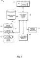
- FIGURE 1illustrates one embodiment of a vehicle computer system 100 according to various aspects of the present disclosure.
- the system 100includes at least one electronic control unit (ECU) 106.
- ECUsare embedded devices that control electronic systems or subsystems in vehicles. Although only one ECU is shown in FIGURE 1 for ease of illustration, vehicle computer systems may include many ECUs, some of which may be dedicated to controlling specific vehicle systems or subsystems.
- ECUscan be implemented in a variety of hardware, software, and combination hardware/software configurations, for carrying out aspects of the present disclosure.
- a typical ECUincludes a processor (e.g., a microcontroller), memory, and one or more communication links.
- the memorymay include an electronically erasable, programmable, read-only memory (“EEPROM”) or other non-volatile memory (e.g., flash memory) and/or random access memory (“RAM”).
- EEPROMelectronically erasable, programmable, read-only memory
- RAMrandom access memory
- the memorymay include program instructions in the form of modules, applications, and/or the like that are executable by the processor.
- the memorymay include program instructions that implement functionality of the system 100.
- the ECU 106communicates with an operator interface 112 comprising an operator display 102.
- the operator display 102may include any type of display (e.g., an LCD display) used in a vehicle to convey information (e.g., trailer angle information, blindspot object detection information, or other vehicle information) to the operator.
- the operator display 102may include special purpose lighted displays, needle gauges, and/or the like. In some configurations, such as a touchscreen configuration, the operator display 102 may have input capabilities in addition to output capabilities.
- the operator interface 112also may include other input devices including buttons, toggles, keyboards, mechanical levers, and any other devices that allow an operator to provide input to the system 100.
- the operator interface 112also may include other output devices such as speakers or haptic feedback devices to provide information to the operator.
- the ECU 106is communicatively coupled to a LiDAR system 110.
- the LiDAR system 110obtains information from one or more laser scanners 140 to facilitate calculation of a trailer angle, as described in further detail below.
- a trailer anglecan be calculated, for example, between a trailer and a tractor unit or between a first trailer and a second trailer in a multi-trailer configuration.
- the LiDAR system 110includes a shape detection module 150 that implements a shape detection algorithm.
- the shape detection module 150allows the LiDAR system 110 to detect a trailer, and may provide the ability to detect other objects, as well.
- the LiDAR systemalso includes an angle estimation module 160 that implements an angle estimation algorithm.
- the shape detection module 150can generate output in the form of coordinate points (e.g., coordinate points associated with a trailer or other object).
- the LiDAR system 110may use the shape detection module 150 to distinguish coordinate points associated with a trailer from coordinate points associated with some other object, such as another vehicle or an obstacle to be avoided.
- the LiDAR system 110can take output from the shape detection module 150 and provide it as input to the angle estimation module 160.
- the angle estimation module 160allows the LiDAR system to calculate cab-trailer angles (e.g., angles between tractor units and trailers of a truck), trailer-trailer angles (e.g., angles between connected trailers in a multi-trailer configuration), or the like. Illustrative techniques for calculating trailer angles are described in further detail below.
- the LiDAR system 110can be used in combination with other modules or subsystems to provide enhanced functionality for the vehicle.
- the LiDAR systemis communicatively coupled to an autonomous operation module 120 via the ECU 106.
- the autonomous operation module 120provides functionality for autonomous or computer-guided truck operations.
- autonomous operationssuch as a fully-automated backing or parking maneuver
- no operator actionmay be required to complete the operation.
- computer-guided operationsthe operator may receive guidance (e.g., via display 102) as to how the operation (such as a backing maneuver) may be completed, such as guidance directed to how to steer the tractor unit of a truck in a particular way to complete the operation.
- the autonomous operation modulereceives input from the LiDAR system 110.
- Input received by the autonomous operation module 120may include, for example, shape detection information, trailer angles, trailer dimensions, or the like.
- the autonomous operation module 120may use trailer dimensions and a calculated trailer angle to make a prediction for the location of the extents and path of a trailer during a maneuver.
- Such predictionscan be used, for example, in safety algorithms or route-planning algorithms to prevent the vehicle or trailer from coming into contact with objects (such as buildings, walls, gates, road signs, or the like) or entering hazardous areas, such as a severely sloped area.
- wheel locations or trailer axle locationsare provided for a specific trailer, such predictions also could be used to track the expected path of specific wheels to avoid driving the wheels into hazardous areas.
- the estimated location of the back of the trailercould be used in an algorithm configured to place the trailer in a desired location (e.g., at a loading dock) while avoiding obstacles (such as other parked trailers), hazardous areas, etc.
- the LiDAR system 110also can be used for other purposes.
- the front surface of a trailercan be recognized to allow a tractor unit to center the fifth wheel on the kingpin to allow autonomous mating to the trailer.
- trailer angle calculationscan be used in a jackknife prevention system to provide a warning or actively intervene (e.g., by braking) if a jackknife is imminent by using the trailer angle to determine if the trailer body will come into contact with the tractor cab.
- the LiDAR systemis communicatively coupled to one or more vehicle control modules 116 via the ECU 106.
- the modules 116may include an ABS/stability control module, a blindspot detection or another object detection module, or other vehicle control modules.
- the LiDAR systemmay provide additional functionality when combined with such modules in the system 100.
- the LiDAR systemmay provide trailer angle information that an ABS/stability control module can use to determine if a trailer is sliding out of parallel with the truck.
- the ABS/stability control modulecan then take action (such as braking or reducing engine power) to mitigate the risk of such an event.
- the ECU 106also may be communicatively coupled to one or more other sensors, modules, or subsystems (not shown) that may provide other control capabilities or information concerning the status of the vehicle.
- a GPS module or other vehicle positioning modulecan be used in combination with the LiDAR system 110 to facilitate route-planning for autonomous or computer-guided vehicle operation.
- the illustrated ECU 106is also communicatively coupled to a vehicle data store 104, which may be used to store laser scanner data or other vehicle data.
- vehicle data store 104is depicted a single data store separate from other components of the system 100 for ease of illustration, vehicle data may be distributed among various data stores within the system, including in memory in the ECUs 106 or in other locations. Any suitable computer-readable storage medium, such as an EEPROM, flash memory, hard disk, or the like may be used.
- Data stored in the vehicle data storemay include, for example, vehicle data that can be sensed and stored during vehicle operation, as well as system settings, which may be default settings or customizable settings that can be set by the vehicle manufacturer, the owner, the operator, or any other suitable entity.
- components described hereinmay be communicatively coupled by any suitable means.
- componentsmay be connected by an internal communications network such as a vehicle bus that uses a controller area network (CAN) protocol, a local interconnect network (LIN) protocol, and/or the like.
- vehicle busmay be implemented using any number of different communication protocols such as, but not limited to, Society of Automotive Engineers ("SAE”) J1587, SAE J1922, SAE J1939, SAE J1708, and combinations thereof.
- SAESociety of Automotive Engineers
- componentsmay be connected by other networking protocols, such as Ethernet, Bluetooth, TCP/IP, and/or the like.
- componentsmay be directly connected to each other without the use of a vehicle bus, such as by direct wired connections between the components.
- Embodiments of the present disclosuremay be implemented using other types of currently existing or yet-to-be-developed in-vehicle communication systems without departing from the scope of the claimed subject matter.
- a suitably equipped vehiclemay communicate with other computer systems, e.g., via a WiFi or cellular network.
- Such systemsmay provide remote data processing and storage services, remote diagnostics services, or other services that can be used in combination with the systems and techniques described herein.
- the system 100may communicate with a remote geolocation or positioning system to facilitate autonomous or computer-guided vehicle operation.
- the system 100may transmit status information (e.g., for the LiDAR system 110) to a remote diagnostics system to allow the remote diagnostics system to determine whether components of the system 100 (e.g., LiDAR system 110) or other vehicle systems are operating correctly.
- the LiDAR system 110is depicted in FIGURE 1 as including a shape detection module and an angle estimation module, this is not required. Shape detection and angle estimation can be performed within the LiDAR system 110 or somewhere else, such as in the autonomous operation module 120. In such a configuration, the LiDAR system 110 may provide coordinate point information to the autonomous operation module 120, a blindspot object detection module (not shown), or some other module to perform any necessary calculations.
- a fully-functional vehicle computer systemmay have additional components (e.g., sensors, control modules, output devices, input devices, and the like) that are not shown in FIGURE 1 for ease of illustration.
- FIGURES 2-7Detailed examples are now described with reference to FIGURES 2-7 . However, it should be understood that alternative systems and methods can be implemented and used in accordance with the present disclosure.
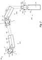
- FIGURES 2 and 3are schematic diagrams of an illustrative autonomous or computer-guided truck maneuver that can be performed by a truck with a LiDAR system in accordance with the present disclosure.
- a tractor unit 210 with a connected trailer 212performs a backing maneuver 200 along a path 204 in which the cab-trailer angle between the tractor unit 210 and the trailer 212 changes during the maneuver.
- the cab-trailer angles B and Care illustrated relative to a center line 216 of the tractor unit 210 and a center line 218 of the trailer 212.
- the tractor unit 210may have one or more LiDAR devices (e.g., 2D or 3D laser scanners) in a LiDAR system that can be used to detect the cab-trailer angle during the backing maneuver 200 or some other maneuver.
- LiDAR devicese.g., 2D or 3D laser scanners
- 2D laser scannersare used, and laser light from the scanners is emitted in a plane to provide two-dimensional positioning information.
- 3D laser scannerscan be used to provide three-dimensional positioning information.
- 3D laser scannersmay be beneficial in scenarios such as detecting flatbed trailers or other lower profile trailers, or for driving over uneven ground.
- 2D and 3D laser scannerscan be used in combination.
- Laser scannerscan be mounted in a variety of locations.
- the tractor unit 210has a side-mounted scanner 140A mounted on each side of the cab (e.g., on left and right rear-view mirrors or some other location).
- the tractor unit 210has a rear-mounted scanner 140B mounted on the rear of the cab (e.g., at a height that provides unobstructed scanning of the front of the trailer 212).
- the tractor unit 210has a side-mounted scanner 140A mounted on each side of the cab and a rear-mounted scanner 140B mounted on the rear of the cab.
- Other locationsare also possible.
- scannersmay be mounted higher or lower on the tractor unit.
- a scannermay be mounted on the rear portion of the roof of the cab for an alternative scanning vantage point.
- a roof-mounted scannermay be positioned, as an example, in the approximate X/Y location represented by rear-mounted scanner 140B, but at a higher position on the rear of the cab.
- the specific locations chosen for scannersmay depend on the specific objects to be detected (e.g., flatbed trailer, box trailer, tank trailer, etc.), the type of scanner used, or other factors. If angles for multiple trailers are to be detected, such as angles E and F in the examples shown in FIGURE 5 , side-mounted scanners 140A may be preferred over a single rear-mounted scanner. However, as shown in FIGURE 6 , it is also possible to mount a rear-mounted scanner 140B on both the tractor unit 210 and the first trailer 212A in a multi-trailer configuration to provide angle detection functionality that can cover both the first trailer 212A and a second trailer 212B.
- the cab-trailer angle Bis detected based on information received from one or both of the side-mounted scanners 140A.
- the cab-trailer anglegradually changes to angle C.
- the cab-trailer anglecontinues to change as the truck proceeds in the backing maneuver to position 202C, where the tractor unit 210 and trailer 212 are in alignment at the desired location (e.g., a loading dock, parking space, or the like).
- cab-trailer anglemay be detected by either or both of the side-mounted scanners 140A individually, or by both side-mounted scanners 140A working in combination, which may provide additional coordinate points and more accurate results.
- changes in the cab-trailer angle during the backing maneuvercan be detected based on information received from the rear-mounted scanner 140B.
- the configuration shown in FIGURE 4which includes both side-mounted scanners 140A and a rear-mounted scanner 140B, may be well suited for detecting trailer angles in both single-trailer and multi-trailer configurations.
- the side-mounted scanners 140Aemit laser light in a range represented by angle A.
- the rear-mounted scanner 140Bemits laser light in a range represented by angle D, which may be the same as or different than the angle A shown in FIGURE 2 , 4, and 5 .
- the angles A and Dmay be wider or narrower depending on the type of scanner used, how the respective scanners are positioned or configured, or other factors.
- the laser scanners 140A, 140Bperform scans and produce output in the form of coordinate values (e.g., x- and y-coordinates for 2D laser scanners, and x-, y-, and z-coordinates for 3D laser scanners).
- the scansmay involve steering a laser beam (e.g., with moveable mirrors) in a predetermined scanning motion (e.g., in the ranges represented by angles A and D).
- the scansare typically performed multiple times per second, and each scan may produce many coordinate points (e.g., hundreds of coordinate points per scan).
- the pointsmay be located at the front and/or sides of the trailer, depending on the location of the scanners being used.
- Other scanner locationse.g., the roof of the cab
- the particular scanning technique that is used, the scan frequency, and the number of coordinate points per scanmay vary depending on factors such as on the particular scanners used, the configuration of the particular scanners used. For example, 2D laser scanners may produce coordinate points along a single scan line. On the other hand, the number of coordinate points may be multiplied for 3D laser scanners that produce coordinate points along multiple scan lines.
- the LiDAR systemuses a shape detection algorithm to distinguish coordinate points associated with the trailer 212 from coordinate points associated with some other object, such as a feature of the tractor unit 210 or another vehicle.
- the shape detection algorithmcan generate output in the form of coordinate points associated with the trailer 212, and the LiDAR system can take this output and provide it as input to an angle estimation algorithm.
- the dimensions of the trailercan be provided as input to the truck's LiDAR system (e.g., when the tractor unit is connected to the trailer, during installation of laser scanners, or at some other time). For example, a truck operator may be prompted to enter the dimensions for a trailer.
- the trailer dimensionscould be provided to or obtained by the LiDAR system automatically (e.g., by looking up dimensions for a trailer identified by type or ID number in a database), which may help to avoid problems caused by manual data entry errors.
- the locations of the laser scannerscan be provided as input to the truck's LiDAR system (e.g., during an initial configuration of the LiDAR system, during installation of laser scanners, or at some other time). Providing the locations of the laser scanners allows the LiDAR system to know where the coordinate origins of the respective laser scanners are, relative to the truck (e.g., relative to a center point or center line the truck). In the examples shown in FIGURES 3 and 4 , the rear-mounted scanner 140B is shown as being positioned along the center line 216 of the tractor unit 210, which may allow for simpler calculations. However, other positions of laser scanners can be easily accommodated (e.g., with offset values that represent a distance between the laser scanner and the center line).
- the angle estimation algorithmperforms the following steps to calculate a cab-trailer angle (e.g., the cab-trailer angles B and C shown in FIGURES 2 and 3 ):
- the trailer orientationmay be represented for the purposes of this calculation by a line, such as the center line 218 shown in FIGURES 2 and 3 .
- Similar calculationscan be performed for vehicles with multiple trailers.
- the respective orientations of trailers 212A and 212Bmay be represented by the center lines 218A and 218B in calculations of the cab-trailer angle E and the trailer-trailer angle F, respectively.
- An angle between the tractor unit 210 and the trailer 212Bcould also be calculated, e.g., by extending the center lines 216 and 218B and calculating the angle between them, or by performing a calculation based on previously calculated angles E and F.
- FIGURE 7is a flow diagram of an illustrative method 700 that may be implemented by the vehicle computer system 100 described above, or by some other vehicle computer system to calculate a trailer angle in accordance with the present disclosure.
- the systemdetects a trailer based on information obtained from one or more laser scanners (e.g., side-mounted laser scanners, a rear-mounted laser scanner, etc.) mounted on a vehicle.
- the systemcalculates the orientation of the detected trailer. For example, an angle detection module calculates the angle of the trailer relative to the respective laser scanner and calculates the orientation of the trailer based on the trailer dimensions (e.g., width and length) and the angle of the trailer relative to the respective laser scanner.
- the systemcalculates a trailer angle (e.g., a cab-trailer angle) for the vehicle based on the orientation of the detected trailer. For example, the system may calculate the cab-trailer angle as the angle between a line representing the calculated trailer orientation and the center line of a tractor unit.
- a trailer anglee.g., a cab-trailer angle
- described processing stagescan be separated into additional stages or combined into fewer stages. Described processing stages also can be omitted or supplemented with other processing stages. Furthermore, processing stages that are described as occurring in a particular order can instead occur in a different order and/or in a parallel fashion, with multiple components or software processes concurrently handling one or more of the illustrated processing stages. Processing stages that are indicated as being performed by a particular device or module may instead be performed by one or more other devices or modules.
- some processingmay be performed locally (e.g., by an on-board vehicle computer system) while other processing may be performed remotely (e.g., by a remote server or other computing device that communicates wirelessly with the on-board vehicle computing system).
- Systems and techniques described hereinmay apply to, for example, a light-duty truck towing a boat trailer to facilitate autonomous or computer-guided operation of such a vehicle, e.g., by calculating an angle between the truck and the boat trailer during general operation or when backing a boat trailer to a boat ramp.
Landscapes
- Engineering & Computer Science (AREA)
- Transportation (AREA)
- Mechanical Engineering (AREA)
- Automation & Control Theory (AREA)
- Physics & Mathematics (AREA)
- General Physics & Mathematics (AREA)
- Traffic Control Systems (AREA)
- Optical Radar Systems And Details Thereof (AREA)
Description
- Vehicles with articulation points pose difficult challenges for operators. As an example, in a semi-trailer truck configuration with an articulation point between a tractor and a trailer, the operator must carefully monitor the angle between the tractor and the trailer when backing up, in order to successfully achieve the desired position and orientation of the vehicle and avoid jackknifing. Similar challenges may face operators of articulated buses, light-duty trucks with trailers (e.g., boat/vehicle trailers, cargo trailers, etc.), or the like. Traditionally, operators must develop the necessary skills for operating such vehicles over long periods of training, and must monitor the angle of the trailer via rear-view mirrors during operation. For operators of any skill level, and especially lower skill levels, a greater level of precision and reduced reliance on visual monitoring is desirable (see for example
DE 10 2012 006 738 ). - With recent advances in technology, autonomous vehicles (such as so-called "driverless cars") are becoming more viable. However, articulation points pose special challenges for autonomous vehicles, as well.
- This summary is provided to introduce a selection of concepts in a simplified form that are further described below in the Detailed Description. This summary is not intended to identify key features of the claimed subject matter, nor is it intended to be used as an aid in determining the scope of the claimed subject matter.
- In one aspect, a vehicle comprises one or more laser scanners and an on-board vehicle computer system communicatively coupled to the laser scanners. The computer system is configured to use information (e.g., coordinate points) obtained from the laser scanners to calculate a cab-trailer angle for the vehicle. The computer system may include a shape detection module configured to detect a trailer based at least in part on the information obtained from the laser scanners. The computer system may include an angle detection module. The angle detection module may be configured to calculate an angle of the detected trailer relative to the laser scanner, calculate the orientation of the detected trailer based on that angle and dimensions (e.g., width and length) of the trailer, and calculate the cab-trailer angle based at least in part on the orientation of the trailer. The computer system may include an autonomous operation module configured to use the cab-trailer angle in an autonomous or computer-guided vehicle maneuver, such as a parking maneuver or backing maneuver. The laser scanners may be mounted on the side or rear of the vehicle.
- In another aspect, a vehicle comprises a tractor unit, a plurality of laser scanners (e.g., at least two side-mounted scanners) mounted to the tractor unit, and an on-board vehicle computer system communicatively coupled to the laser scanners. The computer system is configured to use coordinate point information obtained from at least one of the laser scanners to calculate a cab-trailer angle for the vehicle in a single-trailer or multi-trailer configuration or a trailer-trailer angle for the vehicle in a multi-trailer configuration. The computer system may include an autonomous operation module configured to use the cab-trailer angle or the trailer-trailer angle to perform an autonomous or computer-guided vehicle maneuver. The computer system may include a shape detection module configured to detect one or more trailers based at least in part on the information obtained from the at least one laser scanner. The computer system may include an angle detection module configured to calculate the cab-trailer angle or the trailer-trailer angle based at least in part on an orientation of the detected trailer.
- In another aspect, a computer-readable storage medium includes instructions configured to cause a vehicle computer system to detect a trailer based at least in part on information obtained from a laser scanner mounted on a vehicle, calculate an orientation of the detected trailer, and calculate a trailer angle for the vehicle based at least in part on the orientation of the detected trailer. The instructions may be further configured to cause the vehicle computer system to cause the vehicle to perform an autonomous vehicle maneuver based at least in part on the trailer angle.
- The foregoing aspects and many of the attendant advantages will become more readily appreciated as the same become better understood by reference to the following detailed description, when taken in conjunction with the accompanying drawings, wherein:
FIGURE 1 is a schematic diagram of an illustrative on-board vehicle computer system with a LiDAR system in accordance with the present disclosure;FIGURES 2 and3 are schematic diagrams of an illustrative autonomous or computer-guided truck maneuver that can be performed by a truck with a LiDAR system in accordance with the present disclosure;FIGURES 4-6 are top views of illustrative vehicles with laser scanners in accordance with the present disclosure; andFIGURE 7 is a flow chart of an illustrative method that may be implemented by a computer system such as the on-board vehicle computer system ofFIGURE 1 .- The detailed description set forth below in connection with the appended drawings is an illustrative and non-limiting description of various embodiments of the disclosed subject matter. The following description proceeds with reference to examples of computer systems and methods suitable for use in vehicles, such as Class 8 trucks. Although illustrative embodiments of the present disclosure will be described hereinafter with reference to trucks, it will be appreciated that aspects of the present disclosure have wide application, and therefore, may be suitable for use with many types of vehicles, such as passenger vehicles, buses, commercial vehicles, light and medium duty vehicles, etc.
- Examples described herein provide enhanced vehicle operation and object detection capabilities with light-based remote-sensing technology. As used herein, the term LiDAR (also known as light radar or light detection and ranging) is used to refer generally to light-based remote sensing technology. Laser scanners are devices that use LiDAR technology for remote sensing. The laser scanners described herein may employ any suitable known or future-developed LiDAR technology to perform functions described herein.
- It should be understood that various embodiments of the present disclosure include logic and operations performed by electronic components. These electronic components, which may be grouped in a single location or distributed over a wide area, generally include processors, memory, storage devices, display devices, input devices, sensors, etc. It will be appreciated by one skilled in the art that the logic described herein may be implemented in a variety of hardware, software, and combination hardware/software configurations, including but not limited to, analog circuitry, digital circuitry, processing units, and the like. In circumstances where the components are distributed, the components are accessible to each other via communication links. A controller area network (CAN) bus can be used to communicate vehicle operating conditions as specified by the Society of Automotive Engineers (SAE) J1939 standard.
FIGURE 1 illustrates one embodiment of avehicle computer system 100 according to various aspects of the present disclosure. Thesystem 100 includes at least one electronic control unit (ECU) 106. ECUs are embedded devices that control electronic systems or subsystems in vehicles. Although only one ECU is shown inFIGURE 1 for ease of illustration, vehicle computer systems may include many ECUs, some of which may be dedicated to controlling specific vehicle systems or subsystems. ECUs can be implemented in a variety of hardware, software, and combination hardware/software configurations, for carrying out aspects of the present disclosure. A typical ECU includes a processor (e.g., a microcontroller), memory, and one or more communication links. The memory may include an electronically erasable, programmable, read-only memory ("EEPROM") or other non-volatile memory (e.g., flash memory) and/or random access memory ("RAM"). The memory may include program instructions in the form of modules, applications, and/or the like that are executable by the processor. In particular, the memory may include program instructions that implement functionality of thesystem 100.- The ECU 106 communicates with an
operator interface 112 comprising anoperator display 102. Theoperator display 102 may include any type of display (e.g., an LCD display) used in a vehicle to convey information (e.g., trailer angle information, blindspot object detection information, or other vehicle information) to the operator. Theoperator display 102 may include special purpose lighted displays, needle gauges, and/or the like. In some configurations, such as a touchscreen configuration, theoperator display 102 may have input capabilities in addition to output capabilities. Theoperator interface 112 also may include other input devices including buttons, toggles, keyboards, mechanical levers, and any other devices that allow an operator to provide input to thesystem 100. Theoperator interface 112 also may include other output devices such as speakers or haptic feedback devices to provide information to the operator. - The ECU 106 is communicatively coupled to a
LiDAR system 110. In the example shown inFIGURE 1 , the LiDARsystem 110 obtains information from one ormore laser scanners 140 to facilitate calculation of a trailer angle, as described in further detail below. For a truck, a trailer angle can be calculated, for example, between a trailer and a tractor unit or between a first trailer and a second trailer in a multi-trailer configuration. In the example shown inFIGURE 1 , the LiDARsystem 110 includes ashape detection module 150 that implements a shape detection algorithm. Theshape detection module 150 allows the LiDARsystem 110 to detect a trailer, and may provide the ability to detect other objects, as well. The LiDAR system also includes anangle estimation module 160 that implements an angle estimation algorithm. Theshape detection module 150 can generate output in the form of coordinate points (e.g., coordinate points associated with a trailer or other object). TheLiDAR system 110 may use theshape detection module 150 to distinguish coordinate points associated with a trailer from coordinate points associated with some other object, such as another vehicle or an obstacle to be avoided. TheLiDAR system 110 can take output from theshape detection module 150 and provide it as input to theangle estimation module 160. Theangle estimation module 160 allows the LiDAR system to calculate cab-trailer angles (e.g., angles between tractor units and trailers of a truck), trailer-trailer angles (e.g., angles between connected trailers in a multi-trailer configuration), or the like. Illustrative techniques for calculating trailer angles are described in further detail below. - The
LiDAR system 110 can be used in combination with other modules or subsystems to provide enhanced functionality for the vehicle. In the example shown inFIGURE 1 , the LiDAR system is communicatively coupled to anautonomous operation module 120 via theECU 106. Theautonomous operation module 120 provides functionality for autonomous or computer-guided truck operations. In autonomous operations, such as a fully-automated backing or parking maneuver, no operator action may be required to complete the operation. In computer-guided operations, the operator may receive guidance (e.g., via display 102) as to how the operation (such as a backing maneuver) may be completed, such as guidance directed to how to steer the tractor unit of a truck in a particular way to complete the operation. - In the example shown in
FIGURE 1 , the autonomous operation module receives input from theLiDAR system 110. Input received by theautonomous operation module 120 may include, for example, shape detection information, trailer angles, trailer dimensions, or the like. For example, theautonomous operation module 120 may use trailer dimensions and a calculated trailer angle to make a prediction for the location of the extents and path of a trailer during a maneuver. Such predictions can be used, for example, in safety algorithms or route-planning algorithms to prevent the vehicle or trailer from coming into contact with objects (such as buildings, walls, gates, road signs, or the like) or entering hazardous areas, such as a severely sloped area. If wheel locations or trailer axle locations are provided for a specific trailer, such predictions also could be used to track the expected path of specific wheels to avoid driving the wheels into hazardous areas. For backing maneuvers, the estimated location of the back of the trailer could be used in an algorithm configured to place the trailer in a desired location (e.g., at a loading dock) while avoiding obstacles (such as other parked trailers), hazardous areas, etc. - The
LiDAR system 110 also can be used for other purposes. For example, the front surface of a trailer can be recognized to allow a tractor unit to center the fifth wheel on the kingpin to allow autonomous mating to the trailer. As another example, trailer angle calculations can be used in a jackknife prevention system to provide a warning or actively intervene (e.g., by braking) if a jackknife is imminent by using the trailer angle to determine if the trailer body will come into contact with the tractor cab. - In the example shown in
FIGURE 1 , the LiDAR system is communicatively coupled to one or morevehicle control modules 116 via theECU 106. Themodules 116 may include an ABS/stability control module, a blindspot detection or another object detection module, or other vehicle control modules. The LiDAR system may provide additional functionality when combined with such modules in thesystem 100. For example, the LiDAR system may provide trailer angle information that an ABS/stability control module can use to determine if a trailer is sliding out of parallel with the truck. The ABS/stability control module can then take action (such as braking or reducing engine power) to mitigate the risk of such an event. - The
ECU 106 also may be communicatively coupled to one or more other sensors, modules, or subsystems (not shown) that may provide other control capabilities or information concerning the status of the vehicle. For example, a GPS module or other vehicle positioning module can be used in combination with theLiDAR system 110 to facilitate route-planning for autonomous or computer-guided vehicle operation. - The illustrated
ECU 106 is also communicatively coupled to avehicle data store 104, which may be used to store laser scanner data or other vehicle data. Although thevehicle data store 104 is depicted a single data store separate from other components of thesystem 100 for ease of illustration, vehicle data may be distributed among various data stores within the system, including in memory in theECUs 106 or in other locations. Any suitable computer-readable storage medium, such as an EEPROM, flash memory, hard disk, or the like may be used. Data stored in the vehicle data store may include, for example, vehicle data that can be sensed and stored during vehicle operation, as well as system settings, which may be default settings or customizable settings that can be set by the vehicle manufacturer, the owner, the operator, or any other suitable entity. - Components described herein may be communicatively coupled by any suitable means. In one embodiment, components may be connected by an internal communications network such as a vehicle bus that uses a controller area network (CAN) protocol, a local interconnect network (LIN) protocol, and/or the like. Those of ordinary skill in the art will recognize that the vehicle bus may be implemented using any number of different communication protocols such as, but not limited to, Society of Automotive Engineers ("SAE") J1587, SAE J1922, SAE J1939, SAE J1708, and combinations thereof. In other embodiments, components may be connected by other networking protocols, such as Ethernet, Bluetooth, TCP/IP, and/or the like. In still other embodiments, components may be directly connected to each other without the use of a vehicle bus, such as by direct wired connections between the components. Embodiments of the present disclosure may be implemented using other types of currently existing or yet-to-be-developed in-vehicle communication systems without departing from the scope of the claimed subject matter.
- Although the
system 100 is depicted as an on-board vehicle computer system to illustrate one category of usage scenarios, other configurations are possible. A suitably equipped vehicle may communicate with other computer systems, e.g., via a WiFi or cellular network. Such systems may provide remote data processing and storage services, remote diagnostics services, or other services that can be used in combination with the systems and techniques described herein. For example, thesystem 100 may communicate with a remote geolocation or positioning system to facilitate autonomous or computer-guided vehicle operation. As another example, thesystem 100 may transmit status information (e.g., for the LiDAR system 110) to a remote diagnostics system to allow the remote diagnostics system to determine whether components of the system 100 (e.g., LiDAR system 110) or other vehicle systems are operating correctly. - Many alternatives to the vehicles and systems described herein are possible. Although illustrative details of vehicle computer systems are described with reference to
FIGURE 1 , it should be understood that alternative systems and methods can be implemented and used in accordance with the present disclosure. For example, although theLiDAR system 110 is depicted inFIGURE 1 as including a shape detection module and an angle estimation module, this is not required. Shape detection and angle estimation can be performed within theLiDAR system 110 or somewhere else, such as in theautonomous operation module 120. In such a configuration, theLiDAR system 110 may provide coordinate point information to theautonomous operation module 120, a blindspot object detection module (not shown), or some other module to perform any necessary calculations. - Further, it should be understood that, in practice, a fully-functional vehicle computer system may have additional components (e.g., sensors, control modules, output devices, input devices, and the like) that are not shown in
FIGURE 1 for ease of illustration. - Detailed examples are now described with reference to
FIGURES 2-7 . However, it should be understood that alternative systems and methods can be implemented and used in accordance with the present disclosure. - As mentioned above, a LiDAR system can be used to facilitate autonomous or computer-guided truck operation.
FIGURES 2 and3 are schematic diagrams of an illustrative autonomous or computer-guided truck maneuver that can be performed by a truck with a LiDAR system in accordance with the present disclosure. As shown, atractor unit 210 with aconnected trailer 212 performs abacking maneuver 200 along apath 204 in which the cab-trailer angle between thetractor unit 210 and thetrailer 212 changes during the maneuver. In the examples shown inFIGURES 2 and3 , the cab-trailer angles B and C are illustrated relative to acenter line 216 of thetractor unit 210 and acenter line 218 of thetrailer 212. - The
tractor unit 210 may have one or more LiDAR devices (e.g., 2D or 3D laser scanners) in a LiDAR system that can be used to detect the cab-trailer angle during thebacking maneuver 200 or some other maneuver. In at least one embodiment, 2D laser scanners are used, and laser light from the scanners is emitted in a plane to provide two-dimensional positioning information. Alternatively, 3D laser scanners can be used to provide three-dimensional positioning information. 3D laser scanners may be beneficial in scenarios such as detecting flatbed trailers or other lower profile trailers, or for driving over uneven ground. Or, 2D and 3D laser scanners can be used in combination. - Laser scanners can be mounted in a variety of locations. In the example shown in
FIGURE 2 , thetractor unit 210 has a side-mountedscanner 140A mounted on each side of the cab (e.g., on left and right rear-view mirrors or some other location). In the example shown inFIGURE 3 , thetractor unit 210 has a rear-mountedscanner 140B mounted on the rear of the cab (e.g., at a height that provides unobstructed scanning of the front of the trailer 212). In the example shown inFIGURE 4 , thetractor unit 210 has a side-mountedscanner 140A mounted on each side of the cab and a rear-mountedscanner 140B mounted on the rear of the cab. Other locations are also possible. For example, scanners may be mounted higher or lower on the tractor unit. Referring toFIGURE 3 , a scanner may be mounted on the rear portion of the roof of the cab for an alternative scanning vantage point. A roof-mounted scanner may be positioned, as an example, in the approximate X/Y location represented by rear-mountedscanner 140B, but at a higher position on the rear of the cab. - In practice, the specific locations chosen for scanners may depend on the specific objects to be detected (e.g., flatbed trailer, box trailer, tank trailer, etc.), the type of scanner used, or other factors. If angles for multiple trailers are to be detected, such as angles E and F in the examples shown in
FIGURE 5 , side-mountedscanners 140A may be preferred over a single rear-mounted scanner. However, as shown inFIGURE 6 , it is also possible to mount a rear-mountedscanner 140B on both thetractor unit 210 and thefirst trailer 212A in a multi-trailer configuration to provide angle detection functionality that can cover both thefirst trailer 212A and asecond trailer 212B. - Referring again to the example shown in
FIGURE 2 , atposition 202A of themaneuver 200, the cab-trailer angle B is detected based on information received from one or both of the side-mountedscanners 140A. As the truck proceeds in the backing maneuver to position 202B, the cab-trailer angle gradually changes to angle C. The cab-trailer angle continues to change as the truck proceeds in the backing maneuver to position 202C, where thetractor unit 210 andtrailer 212 are in alignment at the desired location (e.g., a loading dock, parking space, or the like). Depending on the physical characteristics of thetractor unit 210 and thetrailer 212, the orientation or positioning of the side-mountedscanners 140A, or other factors, cab-trailer angle may be detected by either or both of the side-mountedscanners 140A individually, or by both side-mountedscanners 140A working in combination, which may provide additional coordinate points and more accurate results. Referring again to the example shown inFIGURE 3 , changes in the cab-trailer angle during the backing maneuver can be detected based on information received from the rear-mountedscanner 140B. The configuration shown inFIGURE 4 , which includes both side-mountedscanners 140A and a rear-mountedscanner 140B, may be well suited for detecting trailer angles in both single-trailer and multi-trailer configurations. - In the examples shown in
FIGURES 2 ,4, and 5 , the side-mountedscanners 140A emit laser light in a range represented by angle A. In the examples shown inFIGURES 3 ,4 , and6 , the rear-mountedscanner 140B emits laser light in a range represented by angle D, which may be the same as or different than the angle A shown inFIGURE 2 ,4, and 5 . In practice, the angles A and D may be wider or narrower depending on the type of scanner used, how the respective scanners are positioned or configured, or other factors. - In the examples shown in
FIGURES 2-6 , thelaser scanners FIGURES 2-6 , the points may be located at the front and/or sides of the trailer, depending on the location of the scanners being used. Other scanner locations (e.g., the roof of the cab) may be better suited for identifying points located in other areas, such as the top of the trailer. - The particular scanning technique that is used, the scan frequency, and the number of coordinate points per scan may vary depending on factors such as on the particular scanners used, the configuration of the particular scanners used. For example, 2D laser scanners may produce coordinate points along a single scan line. On the other hand, the number of coordinate points may be multiplied for 3D laser scanners that produce coordinate points along multiple scan lines.
- In at least one embodiment, the LiDAR system uses a shape detection algorithm to distinguish coordinate points associated with the
trailer 212 from coordinate points associated with some other object, such as a feature of thetractor unit 210 or another vehicle. The shape detection algorithm can generate output in the form of coordinate points associated with thetrailer 212, and the LiDAR system can take this output and provide it as input to an angle estimation algorithm. - The dimensions of the trailer can be provided as input to the truck's LiDAR system (e.g., when the tractor unit is connected to the trailer, during installation of laser scanners, or at some other time). For example, a truck operator may be prompted to enter the dimensions for a trailer. Alternatively, the trailer dimensions could be provided to or obtained by the LiDAR system automatically (e.g., by looking up dimensions for a trailer identified by type or ID number in a database), which may help to avoid problems caused by manual data entry errors.
- The locations of the laser scanners can be provided as input to the truck's LiDAR system (e.g., during an initial configuration of the LiDAR system, during installation of laser scanners, or at some other time). Providing the locations of the laser scanners allows the LiDAR system to know where the coordinate origins of the respective laser scanners are, relative to the truck (e.g., relative to a center point or center line the truck). In the examples shown in
FIGURES 3 and4 , the rear-mountedscanner 140B is shown as being positioned along thecenter line 216 of thetractor unit 210, which may allow for simpler calculations. However, other positions of laser scanners can be easily accommodated (e.g., with offset values that represent a distance between the laser scanner and the center line). - In at least one embodiment, the angle estimation algorithm performs the following steps to calculate a cab-trailer angle (e.g., the cab-trailer angles B and C shown in
FIGURES 2 and3 ): - 1. Calculate the angle of the trailer relative to the respective laser scanner, e.g., by calculating a best-fit line through the respective coordinate points;
- 2. Calculate the orientation of the
trailer 212 based on the best-fit line and the trailer dimensions (e.g., width and length); and - 3. Calculate the cab-trailer angle as the angle between the calculated trailer orientation and the
center line 216 of thetractor unit 210. - The trailer orientation may be represented for the purposes of this calculation by a line, such as the
center line 218 shown inFIGURES 2 and3 . - Similar calculations can be performed for vehicles with multiple trailers. For example, with reference to
FIGURE 5 , the respective orientations oftrailers center lines tractor unit 210 and thetrailer 212B could also be calculated, e.g., by extending thecenter lines FIGURE 7 is a flow diagram of anillustrative method 700 that may be implemented by thevehicle computer system 100 described above, or by some other vehicle computer system to calculate a trailer angle in accordance with the present disclosure. Atstep 710, the system detects a trailer based on information obtained from one or more laser scanners (e.g., side-mounted laser scanners, a rear-mounted laser scanner, etc.) mounted on a vehicle. Atstep 720, the system calculates the orientation of the detected trailer. For example, an angle detection module calculates the angle of the trailer relative to the respective laser scanner and calculates the orientation of the trailer based on the trailer dimensions (e.g., width and length) and the angle of the trailer relative to the respective laser scanner. Atstep 730, the system calculates a trailer angle (e.g., a cab-trailer angle) for the vehicle based on the orientation of the detected trailer. For example, the system may calculate the cab-trailer angle as the angle between a line representing the calculated trailer orientation and the center line of a tractor unit.- Many alternatives to the described methods and algorithms are possible. For example, described processing stages can be separated into additional stages or combined into fewer stages. Described processing stages also can be omitted or supplemented with other processing stages. Furthermore, processing stages that are described as occurring in a particular order can instead occur in a different order and/or in a parallel fashion, with multiple components or software processes concurrently handling one or more of the illustrated processing stages. Processing stages that are indicated as being performed by a particular device or module may instead be performed by one or more other devices or modules. For example, in a cloud computing or remote computing arrangement, some processing may be performed locally (e.g., by an on-board vehicle computer system) while other processing may be performed remotely (e.g., by a remote server or other computing device that communicates wirelessly with the on-board vehicle computing system).
- Although some of the details described herein are described in the context of particular types of vehicles, such as Class 8 trucks, it should be understood that aspects of the systems and related techniques described herein are applicable to other types of vehicles and vehicle configurations. Systems and techniques described herein may apply to, for example, a light-duty truck towing a boat trailer to facilitate autonomous or computer-guided operation of such a vehicle, e.g., by calculating an angle between the truck and the boat trailer during general operation or when backing a boat trailer to a boat ramp.
Claims (11)
- A vehicle comprising:- a tractor unit (210);- a first trailer (212) connected to the tractor unit (210);- a second trailer (212B) connected to the first trailer (212A);- at least one laser scanner (140) mounted on the tractor unit (210);- an on-board vehicle computer system (100) communicatively coupled to the at least one laser scanner (140) mounted on the tractor unit (210), wherein said vehicle further comprises:- at least one additional laser scanner (140) mounted on the first trailer (212) and- whereinthe on-board vehicle computer system (100) communicatively coupled to the at least one additional laser scanner (140) mounted on the first trailer (212),characterized in thatthe on-board vehicle computer system (100) is configured to use information obtained from the at least one laser scanner (140) mounted on the tractor unit (210) to calculate a cab-trailer angle for the vehicle, and wherein the on-board vehicle computer system (100) is further configured to use information obtained from the at least one additional laser scanner (140) mounted on the first trailer (212) to calculate a trailer-trailer angle between the first trailer (212A) and the second trailer (212B) in a multi trailer configuration.
- The vehicle of Claim 1, wherein the on-board vehicle computer system (100) comprises a shape detection module (150).
- The vehicle of Claim 1 or 2, wherein the at least one laser scanner (140) mounted on the tractor unit (210) comprises a side-mounted scanner (140).
- The vehicle of one of claims 1 to 3, wherein the at least one laser scanner (140) or the at least one additional laser scanner (140) comprises a rear-mounted or roof-mounted scanner (140).
- The vehicle of one of claims 1 to 4, wherein the on-board vehicle computer system (100) comprises an autonomous operation module (120) configured to use the cab-trailer angle to perform an autonomous or computer-guided vehicle maneuver.
- The vehicle of Claim 5, wherein the autonomous or computer-guided vehicle maneuver comprises a parking maneuver.
- The vehicle of Claim 5 or 6, wherein the autonomous or computer-guided vehicle maneuver comprises a backing maneuver.
- The vehicle of one of claims 1 to 7, wherein the at least one laser scanner (140) mounted in the tractor unit (210) comprises at least two side-mounted scanners (140).
- The vehicle of Claim 8, wherein the at least one laser scanner (140) mounted in the tractor unit (210) further comprises a rear-mounted scanner (140).
- The vehicle of one of claims 1 to 9,wherein the at least one laser scanner (140) produce output in the form of coordinate points, wherein the on-board vehicle computer system (100) is configured to estimate the cab-trailer angle based on the coordinate points produced by the at least one laser scanner (140); and/orwherein the at least one additional laser scanner (140) produce output in the form of coordinate points, wherein the on-board vehicle computer system (100) is configured to estimate the trailer-trailer angle based on the coordinate points produced by the at least one additional laser scanner (140).
- The vehicle of claim 10, wherein the on-board vehicle computer system (100) comprises a shape detection module (150) and a angle estimation module (160),wherein the shape detection module (150) is configured to generate coordinate points associated with the first trailer (212) provided as input to the angle estimation module (160); and/orwherein the shape detection module (150) is configured to generate coordinate points associated with the second trailer (212B) provided as input to the angle estimation module (160).
Applications Claiming Priority (2)
| Application Number | Priority Date | Filing Date | Title |
|---|---|---|---|
| US14/745,165US20160368336A1 (en) | 2015-06-19 | 2015-06-19 | Use of laser scanner for autonomous truck operation |
| PCT/US2016/037927WO2016205559A1 (en) | 2015-06-19 | 2016-06-16 | Use of laser scanner for autonomous truck operation |
Publications (3)
| Publication Number | Publication Date |
|---|---|
| EP3310641A1 EP3310641A1 (en) | 2018-04-25 |
| EP3310641A4 EP3310641A4 (en) | 2019-02-27 |
| EP3310641B1true EP3310641B1 (en) | 2021-12-15 |
Family
ID=57546386
Family Applications (1)
| Application Number | Title | Priority Date | Filing Date |
|---|---|---|---|
| EP16812467.5AActiveEP3310641B1 (en) | 2015-06-19 | 2016-06-16 | A vehicle with a laser scanner |
Country Status (5)
| Country | Link |
|---|---|
| US (2) | US20160368336A1 (en) |
| EP (1) | EP3310641B1 (en) |
| AU (1) | AU2016278231B2 (en) |
| CA (1) | CA2989995C (en) |
| WO (1) | WO2016205559A1 (en) |
Families Citing this family (33)
| Publication number | Priority date | Publication date | Assignee | Title |
|---|---|---|---|---|
| CN109891261B (en) | 2016-07-28 | 2023-11-24 | 通用汽车环球科技运作有限责任公司 | Distributed transportation lidar system |
| EP3592627B1 (en)* | 2017-03-06 | 2021-12-15 | Volvo Truck Corporation | Methods for assisting automatic uncoupling/coupling of a trailer |
| US20180372875A1 (en)* | 2017-06-27 | 2018-12-27 | Uber Technologies, Inc. | Sensor configuration for an autonomous semi-truck |
| US20190064828A1 (en)* | 2017-08-29 | 2019-02-28 | Walmart Apollo, Llc | Autonomous yard vehicle system |
| US20190113932A1 (en)* | 2017-10-18 | 2019-04-18 | Trw Automotive U.S. Llc | Apparatus for positioning a trailer |
| US20190129429A1 (en)* | 2017-10-26 | 2019-05-02 | Uber Technologies, Inc. | Systems and Methods for Determining Tractor-Trailer Angles and Distances |
| WO2019118848A1 (en) | 2017-12-15 | 2019-06-20 | Walmart Apollo, Llc | System and method for managing a vehicle storage area |
| CN108278981A (en)* | 2018-02-11 | 2018-07-13 | 北京主线科技有限公司 | Detect the device and its detection method of unmanned trailer axle drift angle |
| WO2019165150A1 (en) | 2018-02-21 | 2019-08-29 | Azevtec, Inc. | Systems and methods for automated operation and handling of autonomous trucks and trailers hauled thereby |
| US11707955B2 (en) | 2018-02-21 | 2023-07-25 | Outrider Technologies, Inc. | Systems and methods for automated operation and handling of autonomous trucks and trailers hauled thereby |
| US12246457B2 (en) | 2018-02-21 | 2025-03-11 | Outrider Technologies, Inc. | System and method for connection of service lines to trailer fronts by automated trucks |
| EP3787912B1 (en)* | 2018-05-01 | 2023-07-12 | Continental Autonomous Mobility US, LLC | Tow vehicle and trailer alignment |
| US10935378B2 (en)* | 2018-05-21 | 2021-03-02 | Tusimple, Inc. | System and method for angle measurement |
| US11643154B2 (en) | 2018-05-30 | 2023-05-09 | Waymo Llc | Systems and methods for automatic air and electrical connections on autonomous cargo vehicles |
| US10807660B2 (en) | 2018-05-30 | 2020-10-20 | Waymo Llc | Systems and methods for automatic air and electrical connections on autonomous cargo vehicles |
| US11066000B2 (en)* | 2018-08-13 | 2021-07-20 | United Parcel Service Of America, Inc. | Systems, methods, and apparatuses for engaging and transporting objects |
| US11858491B2 (en) | 2018-10-30 | 2024-01-02 | Outrider Technologies, Inc. | System and method for controlling braking functions in an autonomous vehicle |
| US11200430B2 (en) | 2018-11-05 | 2021-12-14 | Tusimple, Inc. | Systems and methods for detecting trailer angle |
| US11125881B2 (en) | 2018-12-10 | 2021-09-21 | Waymo Llc | Lidar-based trailer tracking |
| CN116184417A (en) | 2018-12-10 | 2023-05-30 | 北京图森智途科技有限公司 | Trailer pinch angle measuring method and device and vehicle |
| CN111319629B (en) | 2018-12-14 | 2021-07-16 | 北京图森智途科技有限公司 | A method, device and system for forming an autonomous vehicle fleet |
| EP3947112B1 (en)* | 2019-03-25 | 2024-05-08 | Volvo Truck Corporation | A vehicle comprising a trailer angle determining system |
| CN114072314B (en) | 2019-06-26 | 2024-06-11 | 株式会社Ihi | Driving control system |
| US11429106B2 (en) | 2019-09-17 | 2022-08-30 | United Parcel Service Of America, Inc. | Methods and systems for shifting objects |
| US11568563B2 (en) | 2019-12-31 | 2023-01-31 | Trimble Inc. | Pose estimation and applications using computer imaging |
| CN111238366B (en)* | 2020-01-09 | 2021-10-22 | 天远三维(天津)科技有限公司 | Three-dimensional scanning path planning method and device |
| EP4111233A1 (en) | 2020-02-27 | 2023-01-04 | Volvo Truck Corporation | Ad or adas aided maneuvering of a vehicle |
| CN111637852B (en)* | 2020-05-27 | 2023-03-21 | 中国汽车技术研究中心有限公司 | System and method for measuring articulation angle of full-trailer automobile train |
| US11977165B2 (en)* | 2020-08-10 | 2024-05-07 | Waymo Llc | Self-reflection filtering |
| US12049251B2 (en)* | 2021-02-05 | 2024-07-30 | GM Global Technology Operations LLC | Trailer tracking control |
| CA3223658A1 (en)* | 2021-06-23 | 2022-12-29 | Jonathan RECORD | Systems and methods for determining an articulated trailer angle |
| CN113805194B (en)* | 2021-07-30 | 2024-03-29 | 上海西井科技股份有限公司 | Composite navigation system, method, equipment and storage medium of unmanned vehicle functional component |
| US20250060454A1 (en)* | 2023-08-18 | 2025-02-20 | Torc Robotics, Inc. | Systems and methods of monitoring and control for trailer dynamics |
Family Cites Families (31)
| Publication number | Priority date | Publication date | Assignee | Title |
|---|---|---|---|---|
| US6484080B2 (en) | 1995-06-07 | 2002-11-19 | Automotive Technologies International Inc. | Method and apparatus for controlling a vehicular component |
| JPH06278640A (en)* | 1993-03-29 | 1994-10-04 | Nippon Toreele Mobil Kk | Steering device for trailer |
| DE4336288C1 (en) | 1993-10-25 | 1995-03-30 | Daimler Benz Ag | Device for monitoring the rear or front space of a parking motor vehicle |
| JP2722183B2 (en)* | 1995-06-07 | 1998-03-04 | 輸送機工業株式会社 | Semi-trailer connection angle detection device |
| US6550949B1 (en) | 1996-06-13 | 2003-04-22 | Gentex Corporation | Systems and components for enhancing rear vision from a vehicle |
| US7979172B2 (en) | 1997-10-22 | 2011-07-12 | Intelligent Technologies International, Inc. | Autonomous vehicle travel control systems and methods |
| EP0913751B1 (en) | 1997-11-03 | 2003-09-03 | Volkswagen Aktiengesellschaft | Autonomous vehicle and guiding method for an autonomous vehicle |
| JP3721911B2 (en)* | 2000-01-07 | 2005-11-30 | いすゞ自動車株式会社 | Trailer connection angle detector |
| WO2001085491A1 (en) | 2000-05-08 | 2001-11-15 | Automotive Technologies International, Inc. | Vehicular blind spot identification and monitoring system |
| US7852462B2 (en) | 2000-05-08 | 2010-12-14 | Automotive Technologies International, Inc. | Vehicular component control methods based on blind spot monitoring |
| DE10049229A1 (en) | 2000-09-28 | 2002-05-02 | Daimler Chrysler Ag | External area monitoring around a road vehicle to provide a warning to the driver |
| JP2002243423A (en)* | 2000-12-15 | 2002-08-28 | Isuzu Motors Ltd | Trailer connection angle detecting device |
| DE10114932B4 (en) | 2001-03-26 | 2005-09-15 | Daimlerchrysler Ag | Three-dimensional environment detection |
| US9007197B2 (en) | 2002-05-20 | 2015-04-14 | Intelligent Technologies International, Inc. | Vehicular anticipatory sensor system |
| DE10392601D2 (en) | 2002-08-09 | 2005-02-03 | Conti Temic Microelectronic | Transportation with a 3D range camera and method of operation |
| DE102005058628B4 (en)* | 2005-12-07 | 2015-10-22 | Götting KG | Navigation system for a mobile with a towing vehicle and a trailer / semitrailer |
| US8050863B2 (en) | 2006-03-16 | 2011-11-01 | Gray & Company, Inc. | Navigation and control system for autonomous vehicles |
| DE102007061234A1 (en) | 2007-12-19 | 2009-06-25 | Robert Bosch Gmbh | Method and device for adjusting the guidance of a vehicle |
| EP2340980B1 (en) | 2009-12-30 | 2012-05-30 | Magneti Marelli S.p.A. | Parking assistant system |
| US20110210529A1 (en) | 2010-02-26 | 2011-09-01 | Daimler Trucks North America LLC. | Method and apparatus for adjusting the gap of a fifth wheel of a vehicle |
| SE535596C2 (en)* | 2011-02-14 | 2012-10-09 | Scania Cv Ab | Length estimation of vehicles |
| US9374562B2 (en)* | 2011-04-19 | 2016-06-21 | Ford Global Technologies, Llc | System and method for calculating a horizontal camera to target distance |
| DE102012006738A1 (en)* | 2012-03-31 | 2013-10-02 | Hans-Heinrich Götting | Method of controlling group of objects e.g. train with trailer, involves detecting direction, position or location of specific object such as trailer among group of objects such as train or convoy, and comparing to set point |
| US9180882B1 (en) | 2012-06-20 | 2015-11-10 | Google Inc. | Avoiding blind spots of other vehicles |
| US9558409B2 (en)* | 2012-09-26 | 2017-01-31 | Magna Electronics Inc. | Vehicle vision system with trailer angle detection |
| US9367065B2 (en) | 2013-01-25 | 2016-06-14 | Google Inc. | Modifying behavior of autonomous vehicles based on sensor blind spots and limitations |
| GB2515800B (en) | 2013-07-04 | 2017-06-07 | Jaguar Land Rover Ltd | Vehicle control system |
| US9834207B2 (en) | 2014-04-15 | 2017-12-05 | GM Global Technology Operations LLC | Method and system for detecting, tracking and estimating stationary roadside objects |
| DE102014108484B4 (en)* | 2014-06-17 | 2021-07-01 | Robert Bosch Gmbh | METHOD OF ASSISTING A DRIVER WHEN MANEUVERING A DRIVER |
| US9507932B2 (en)* | 2014-09-12 | 2016-11-29 | Alcatel Lucent | Policy enforcement in a topology abstraction system |
| US9315212B1 (en)* | 2014-10-13 | 2016-04-19 | Ford Global Technologies, Llc | Trailer sensor module and associated method of wireless trailer identification and motion estimation |
- 2015
- 2015-06-19USUS14/745,165patent/US20160368336A1/ennot_activeAbandoned
- 2016
- 2016-06-16EPEP16812467.5Apatent/EP3310641B1/enactiveActive
- 2016-06-16AUAU2016278231Apatent/AU2016278231B2/enactiveActive
- 2016-06-16CACA2989995Apatent/CA2989995C/enactiveActive
- 2016-06-16WOPCT/US2016/037927patent/WO2016205559A1/ennot_activeCeased
- 2017
- 2017-09-01USUS15/694,564patent/US10759428B2/enactiveActive
Non-Patent Citations (1)
| Title |
|---|
| None* |
Also Published As
| Publication number | Publication date |
|---|---|
| EP3310641A4 (en) | 2019-02-27 |
| AU2016278231B2 (en) | 2020-07-02 |
| US10759428B2 (en) | 2020-09-01 |
| CA2989995A1 (en) | 2016-12-22 |
| US20170361844A1 (en) | 2017-12-21 |
| US20160368336A1 (en) | 2016-12-22 |
| WO2016205559A1 (en) | 2016-12-22 |
| CA2989995C (en) | 2023-05-02 |
| AU2016278231A1 (en) | 2018-01-18 |
| EP3310641A1 (en) | 2018-04-25 |
Similar Documents
| Publication | Publication Date | Title |
|---|---|---|
| EP3310641B1 (en) | A vehicle with a laser scanner | |
| US12352862B2 (en) | Lidar-based trailer tracking | |
| EP3802283B1 (en) | Autonomous detection of and backing to trailer kingpin | |
| AU2018425454B2 (en) | Systems and methods for autonomously backing a vehicle to a trailer | |
| AU2018425457B2 (en) | Systems and methods for automatically updating a model of vehicle turning dynamics | |
| AU2025203196A1 (en) | Systems and methods for determining a height of an object above a vehicle | |
| AU2018425456B2 (en) | Selection of environment sensors for autonomous vehicle maneuvering | |
| US20250289457A1 (en) | Method for Providing at Least One Trailer Characteristic, Computing Device, Computer-Readable (Storage) Medium, and System | |
| SE541357C2 (en) | Method and control arrangement for modelling spatial movement of a trailer being articulatedly attached to a vehicle | |
| AU2018426291B2 (en) | Systems and methods for autonomously backing a vehicle to a dock | |
| US12377876B2 (en) | Method for planning a driving trajectory defining a travelling path for a vehicle | |
| US12412295B2 (en) | Methods and systems for estimating hitch articulation angle |
Legal Events
| Date | Code | Title | Description |
|---|---|---|---|
| STAA | Information on the status of an ep patent application or granted ep patent | Free format text:STATUS: THE INTERNATIONAL PUBLICATION HAS BEEN MADE | |
| PUAI | Public reference made under article 153(3) epc to a published international application that has entered the european phase | Free format text:ORIGINAL CODE: 0009012 | |
| STAA | Information on the status of an ep patent application or granted ep patent | Free format text:STATUS: REQUEST FOR EXAMINATION WAS MADE | |
| 17P | Request for examination filed | Effective date:20171221 | |
| AK | Designated contracting states | Kind code of ref document:A1 Designated state(s):AL AT BE BG CH CY CZ DE DK EE ES FI FR GB GR HR HU IE IS IT LI LT LU LV MC MK MT NL NO PL PT RO RS SE SI SK SM TR | |
| AX | Request for extension of the european patent | Extension state:BA ME | |
| RIN1 | Information on inventor provided before grant (corrected) | Inventor name:HANKINS, A., BRENT Inventor name:KAHN, WILLIAM, C. | |
| DAV | Request for validation of the european patent (deleted) | ||
| DAX | Request for extension of the european patent (deleted) | ||
| A4 | Supplementary search report drawn up and despatched | Effective date:20190125 | |
| RIC1 | Information provided on ipc code assigned before grant | Ipc:B60D 1/48 20060101ALI20190121BHEP Ipc:B62D 13/00 20060101AFI20190121BHEP Ipc:B62D 53/04 20060101ALI20190121BHEP Ipc:G01B 11/26 20060101ALI20190121BHEP | |
| STAA | Information on the status of an ep patent application or granted ep patent | Free format text:STATUS: EXAMINATION IS IN PROGRESS | |
| 17Q | First examination report despatched | Effective date:20191210 | |
| GRAP | Despatch of communication of intention to grant a patent | Free format text:ORIGINAL CODE: EPIDOSNIGR1 | |
| STAA | Information on the status of an ep patent application or granted ep patent | Free format text:STATUS: GRANT OF PATENT IS INTENDED | |
| INTG | Intention to grant announced | Effective date:20210713 | |
| GRAS | Grant fee paid | Free format text:ORIGINAL CODE: EPIDOSNIGR3 | |
| GRAA | (expected) grant | Free format text:ORIGINAL CODE: 0009210 | |
| STAA | Information on the status of an ep patent application or granted ep patent | Free format text:STATUS: THE PATENT HAS BEEN GRANTED | |
| AK | Designated contracting states | Kind code of ref document:B1 Designated state(s):AL AT BE BG CH CY CZ DE DK EE ES FI FR GB GR HR HU IE IS IT LI LT LU LV MC MK MT NL NO PL PT RO RS SE SI SK SM TR | |
| REG | Reference to a national code | Ref country code:GB Ref legal event code:FG4D Ref country code:CH Ref legal event code:EP | |
| REG | Reference to a national code | Ref country code:IE Ref legal event code:FG4D Ref country code:DE Ref legal event code:R096 Ref document number:602016067447 Country of ref document:DE | |
| REG | Reference to a national code | Ref country code:AT Ref legal event code:REF Ref document number:1455297 Country of ref document:AT Kind code of ref document:T Effective date:20220115 | |
| REG | Reference to a national code | Ref country code:NL Ref legal event code:FP | |
| REG | Reference to a national code | Ref country code:LT Ref legal event code:MG9D | |
| PG25 | Lapsed in a contracting state [announced via postgrant information from national office to epo] | Ref country code:RS Free format text:LAPSE BECAUSE OF FAILURE TO SUBMIT A TRANSLATION OF THE DESCRIPTION OR TO PAY THE FEE WITHIN THE PRESCRIBED TIME-LIMIT Effective date:20211215 Ref country code:LT Free format text:LAPSE BECAUSE OF FAILURE TO SUBMIT A TRANSLATION OF THE DESCRIPTION OR TO PAY THE FEE WITHIN THE PRESCRIBED TIME-LIMIT Effective date:20211215 Ref country code:FI Free format text:LAPSE BECAUSE OF FAILURE TO SUBMIT A TRANSLATION OF THE DESCRIPTION OR TO PAY THE FEE WITHIN THE PRESCRIBED TIME-LIMIT Effective date:20211215 Ref country code:BG Free format text:LAPSE BECAUSE OF FAILURE TO SUBMIT A TRANSLATION OF THE DESCRIPTION OR TO PAY THE FEE WITHIN THE PRESCRIBED TIME-LIMIT Effective date:20220315 | |
| REG | Reference to a national code | Ref country code:AT Ref legal event code:MK05 Ref document number:1455297 Country of ref document:AT Kind code of ref document:T Effective date:20211215 | |
| PG25 | Lapsed in a contracting state [announced via postgrant information from national office to epo] | Ref country code:SE Free format text:LAPSE BECAUSE OF FAILURE TO SUBMIT A TRANSLATION OF THE DESCRIPTION OR TO PAY THE FEE WITHIN THE PRESCRIBED TIME-LIMIT Effective date:20211215 Ref country code:NO Free format text:LAPSE BECAUSE OF FAILURE TO SUBMIT A TRANSLATION OF THE DESCRIPTION OR TO PAY THE FEE WITHIN THE PRESCRIBED TIME-LIMIT Effective date:20220315 Ref country code:LV Free format text:LAPSE BECAUSE OF FAILURE TO SUBMIT A TRANSLATION OF THE DESCRIPTION OR TO PAY THE FEE WITHIN THE PRESCRIBED TIME-LIMIT Effective date:20211215 Ref country code:HR Free format text:LAPSE BECAUSE OF FAILURE TO SUBMIT A TRANSLATION OF THE DESCRIPTION OR TO PAY THE FEE WITHIN THE PRESCRIBED TIME-LIMIT Effective date:20211215 Ref country code:GR Free format text:LAPSE BECAUSE OF FAILURE TO SUBMIT A TRANSLATION OF THE DESCRIPTION OR TO PAY THE FEE WITHIN THE PRESCRIBED TIME-LIMIT Effective date:20220316 | |
| PG25 | Lapsed in a contracting state [announced via postgrant information from national office to epo] | Ref country code:SM Free format text:LAPSE BECAUSE OF FAILURE TO SUBMIT A TRANSLATION OF THE DESCRIPTION OR TO PAY THE FEE WITHIN THE PRESCRIBED TIME-LIMIT Effective date:20211215 Ref country code:SK Free format text:LAPSE BECAUSE OF FAILURE TO SUBMIT A TRANSLATION OF THE DESCRIPTION OR TO PAY THE FEE WITHIN THE PRESCRIBED TIME-LIMIT Effective date:20211215 Ref country code:RO Free format text:LAPSE BECAUSE OF FAILURE TO SUBMIT A TRANSLATION OF THE DESCRIPTION OR TO PAY THE FEE WITHIN THE PRESCRIBED TIME-LIMIT Effective date:20211215 Ref country code:PT Free format text:LAPSE BECAUSE OF FAILURE TO SUBMIT A TRANSLATION OF THE DESCRIPTION OR TO PAY THE FEE WITHIN THE PRESCRIBED TIME-LIMIT Effective date:20220418 Ref country code:ES Free format text:LAPSE BECAUSE OF FAILURE TO SUBMIT A TRANSLATION OF THE DESCRIPTION OR TO PAY THE FEE WITHIN THE PRESCRIBED TIME-LIMIT Effective date:20211215 Ref country code:EE Free format text:LAPSE BECAUSE OF FAILURE TO SUBMIT A TRANSLATION OF THE DESCRIPTION OR TO PAY THE FEE WITHIN THE PRESCRIBED TIME-LIMIT Effective date:20211215 Ref country code:CZ Free format text:LAPSE BECAUSE OF FAILURE TO SUBMIT A TRANSLATION OF THE DESCRIPTION OR TO PAY THE FEE WITHIN THE PRESCRIBED TIME-LIMIT Effective date:20211215 | |
| PG25 | Lapsed in a contracting state [announced via postgrant information from national office to epo] | Ref country code:PL Free format text:LAPSE BECAUSE OF FAILURE TO SUBMIT A TRANSLATION OF THE DESCRIPTION OR TO PAY THE FEE WITHIN THE PRESCRIBED TIME-LIMIT Effective date:20211215 Ref country code:AT Free format text:LAPSE BECAUSE OF FAILURE TO SUBMIT A TRANSLATION OF THE DESCRIPTION OR TO PAY THE FEE WITHIN THE PRESCRIBED TIME-LIMIT Effective date:20211215 | |
| REG | Reference to a national code | Ref country code:DE Ref legal event code:R097 Ref document number:602016067447 Country of ref document:DE | |
| PG25 | Lapsed in a contracting state [announced via postgrant information from national office to epo] | Ref country code:IS Free format text:LAPSE BECAUSE OF FAILURE TO SUBMIT A TRANSLATION OF THE DESCRIPTION OR TO PAY THE FEE WITHIN THE PRESCRIBED TIME-LIMIT Effective date:20220415 | |
| PLBE | No opposition filed within time limit | Free format text:ORIGINAL CODE: 0009261 | |
| STAA | Information on the status of an ep patent application or granted ep patent | Free format text:STATUS: NO OPPOSITION FILED WITHIN TIME LIMIT | |
| PG25 | Lapsed in a contracting state [announced via postgrant information from national office to epo] | Ref country code:DK Free format text:LAPSE BECAUSE OF FAILURE TO SUBMIT A TRANSLATION OF THE DESCRIPTION OR TO PAY THE FEE WITHIN THE PRESCRIBED TIME-LIMIT Effective date:20211215 Ref country code:AL Free format text:LAPSE BECAUSE OF FAILURE TO SUBMIT A TRANSLATION OF THE DESCRIPTION OR TO PAY THE FEE WITHIN THE PRESCRIBED TIME-LIMIT Effective date:20211215 | |
| 26N | No opposition filed | Effective date:20220916 | |
| PG25 | Lapsed in a contracting state [announced via postgrant information from national office to epo] | Ref country code:SI Free format text:LAPSE BECAUSE OF FAILURE TO SUBMIT A TRANSLATION OF THE DESCRIPTION OR TO PAY THE FEE WITHIN THE PRESCRIBED TIME-LIMIT Effective date:20211215 | |
| PG25 | Lapsed in a contracting state [announced via postgrant information from national office to epo] | Ref country code:MC Free format text:LAPSE BECAUSE OF FAILURE TO SUBMIT A TRANSLATION OF THE DESCRIPTION OR TO PAY THE FEE WITHIN THE PRESCRIBED TIME-LIMIT Effective date:20211215 | |
| REG | Reference to a national code | Ref country code:CH Ref legal event code:PL | |
| REG | Reference to a national code | Ref country code:BE Ref legal event code:MM Effective date:20220630 | |
| PG25 | Lapsed in a contracting state [announced via postgrant information from national office to epo] | Ref country code:LU Free format text:LAPSE BECAUSE OF NON-PAYMENT OF DUE FEES Effective date:20220616 Ref country code:LI Free format text:LAPSE BECAUSE OF NON-PAYMENT OF DUE FEES Effective date:20220630 Ref country code:IE Free format text:LAPSE BECAUSE OF NON-PAYMENT OF DUE FEES Effective date:20220616 Ref country code:FR Free format text:LAPSE BECAUSE OF NON-PAYMENT OF DUE FEES Effective date:20220630 Ref country code:CH Free format text:LAPSE BECAUSE OF NON-PAYMENT OF DUE FEES Effective date:20220630 | |
| PG25 | Lapsed in a contracting state [announced via postgrant information from national office to epo] | Ref country code:IT Free format text:LAPSE BECAUSE OF FAILURE TO SUBMIT A TRANSLATION OF THE DESCRIPTION OR TO PAY THE FEE WITHIN THE PRESCRIBED TIME-LIMIT Effective date:20211215 Ref country code:BE Free format text:LAPSE BECAUSE OF NON-PAYMENT OF DUE FEES Effective date:20220630 | |
| PG25 | Lapsed in a contracting state [announced via postgrant information from national office to epo] | Ref country code:HU Free format text:LAPSE BECAUSE OF FAILURE TO SUBMIT A TRANSLATION OF THE DESCRIPTION OR TO PAY THE FEE WITHIN THE PRESCRIBED TIME-LIMIT; INVALID AB INITIO Effective date:20160616 | |
| PG25 | Lapsed in a contracting state [announced via postgrant information from national office to epo] | Ref country code:MK Free format text:LAPSE BECAUSE OF FAILURE TO SUBMIT A TRANSLATION OF THE DESCRIPTION OR TO PAY THE FEE WITHIN THE PRESCRIBED TIME-LIMIT Effective date:20211215 Ref country code:CY Free format text:LAPSE BECAUSE OF FAILURE TO SUBMIT A TRANSLATION OF THE DESCRIPTION OR TO PAY THE FEE WITHIN THE PRESCRIBED TIME-LIMIT Effective date:20211215 | |
| PG25 | Lapsed in a contracting state [announced via postgrant information from national office to epo] | Ref country code:MT Free format text:LAPSE BECAUSE OF FAILURE TO SUBMIT A TRANSLATION OF THE DESCRIPTION OR TO PAY THE FEE WITHIN THE PRESCRIBED TIME-LIMIT Effective date:20211215 | |
| REG | Reference to a national code | Ref country code:DE Ref legal event code:R082 Ref document number:602016067447 Country of ref document:DE Representative=s name:4IP GLEIMPETRI PATENT- UND RECHTSANWALTSPARTNE, DE | |
| PGFP | Annual fee paid to national office [announced via postgrant information from national office to epo] | Ref country code:DE Payment date:20250627 Year of fee payment:10 | |
| PGFP | Annual fee paid to national office [announced via postgrant information from national office to epo] | Ref country code:GB Payment date:20250627 Year of fee payment:10 | |
| PGFP | Annual fee paid to national office [announced via postgrant information from national office to epo] | Ref country code:NL Payment date:20250626 Year of fee payment:10 |