EP3310241B1 - Endoscopic device with drip flange - Google Patents
Endoscopic device with drip flangeDownload PDFInfo
- Publication number
- EP3310241B1 EP3310241B1EP16736303.5AEP16736303AEP3310241B1EP 3310241 B1EP3310241 B1EP 3310241B1EP 16736303 AEP16736303 AEP 16736303AEP 3310241 B1EP3310241 B1EP 3310241B1
- Authority
- EP
- European Patent Office
- Prior art keywords
- drip flange
- endoscopic device
- fluid
- drip
- proximal end
- Prior art date
- Legal status (The legal status is an assumption and is not a legal conclusion. Google has not performed a legal analysis and makes no representation as to the accuracy of the status listed.)
- Not-in-force
Links
- 239000012530fluidSubstances0.000claimsdescription90
- 230000003287optical effectEffects0.000claims1
- 238000012800visualizationMethods0.000claims1
- 238000000034methodMethods0.000description15
- 210000003679cervix uteriAnatomy0.000description6
- 230000008878couplingEffects0.000description5
- 238000010168coupling processMethods0.000description5
- 238000005859coupling reactionMethods0.000description5
- 230000007246mechanismEffects0.000description5
- 230000007704transitionEffects0.000description5
- 230000002745absorbentEffects0.000description4
- 239000002250absorbentSubstances0.000description4
- 238000001356surgical procedureMethods0.000description3
- FAPWRFPIFSIZLT-UHFFFAOYSA-MSodium chlorideChemical compound[Na+].[Cl-]FAPWRFPIFSIZLT-UHFFFAOYSA-M0.000description2
- 238000004891communicationMethods0.000description2
- 230000013011matingEffects0.000description2
- 238000012986modificationMethods0.000description2
- 230000004048modificationEffects0.000description2
- 230000001681protective effectEffects0.000description2
- 239000011780sodium chlorideSubstances0.000description2
- 239000007787solidSubstances0.000description2
- 210000004291uterusAnatomy0.000description2
- 0CC*C(C*)(C1)CC(C)(C)CC1C(*)=*(C)[C@@](C)(CC[C@@](C)N=O)ICChemical compoundCC*C(C*)(C1)CC(C)(C)CC1C(*)=*(C)[C@@](C)(CC[C@@](C)N=O)IC0.000description1
- 230000001419dependent effectEffects0.000description1
- 238000006073displacement reactionMethods0.000description1
- 230000005484gravityEffects0.000description1
- 238000005259measurementMethods0.000description1
- 230000007170pathologyEffects0.000description1
- 230000002572peristaltic effectEffects0.000description1
- 230000035790physiological processes and functionsEffects0.000description1
- 238000009877renderingMethods0.000description1
- 239000002699waste materialSubstances0.000description1
Images


Classifications
- A—HUMAN NECESSITIES
- A61—MEDICAL OR VETERINARY SCIENCE; HYGIENE
- A61B—DIAGNOSIS; SURGERY; IDENTIFICATION
- A61B1/00—Instruments for performing medical examinations of the interior of cavities or tubes of the body by visual or photographical inspection, e.g. endoscopes; Illuminating arrangements therefor
- A61B1/00064—Constructional details of the endoscope body
- A61B1/00071—Insertion part of the endoscope body
- A—HUMAN NECESSITIES
- A61—MEDICAL OR VETERINARY SCIENCE; HYGIENE
- A61B—DIAGNOSIS; SURGERY; IDENTIFICATION
- A61B1/00—Instruments for performing medical examinations of the interior of cavities or tubes of the body by visual or photographical inspection, e.g. endoscopes; Illuminating arrangements therefor
- A61B1/00131—Accessories for endoscopes
- A61B1/00135—Oversleeves mounted on the endoscope prior to insertion
- A—HUMAN NECESSITIES
- A61—MEDICAL OR VETERINARY SCIENCE; HYGIENE
- A61B—DIAGNOSIS; SURGERY; IDENTIFICATION
- A61B1/00—Instruments for performing medical examinations of the interior of cavities or tubes of the body by visual or photographical inspection, e.g. endoscopes; Illuminating arrangements therefor
- A61B1/00131—Accessories for endoscopes
- A61B1/00137—End pieces at either end of the endoscope, e.g. caps, seals or forceps plugs
- A—HUMAN NECESSITIES
- A61—MEDICAL OR VETERINARY SCIENCE; HYGIENE
- A61B—DIAGNOSIS; SURGERY; IDENTIFICATION
- A61B1/00—Instruments for performing medical examinations of the interior of cavities or tubes of the body by visual or photographical inspection, e.g. endoscopes; Illuminating arrangements therefor
- A61B1/012—Instruments for performing medical examinations of the interior of cavities or tubes of the body by visual or photographical inspection, e.g. endoscopes; Illuminating arrangements therefor characterised by internal passages or accessories therefor
- A61B1/015—Control of fluid supply or evacuation
- A—HUMAN NECESSITIES
- A61—MEDICAL OR VETERINARY SCIENCE; HYGIENE
- A61B—DIAGNOSIS; SURGERY; IDENTIFICATION
- A61B1/00—Instruments for performing medical examinations of the interior of cavities or tubes of the body by visual or photographical inspection, e.g. endoscopes; Illuminating arrangements therefor
- A61B1/303—Instruments for performing medical examinations of the interior of cavities or tubes of the body by visual or photographical inspection, e.g. endoscopes; Illuminating arrangements therefor for the vagina, i.e. vaginoscopes
- A—HUMAN NECESSITIES
- A61—MEDICAL OR VETERINARY SCIENCE; HYGIENE
- A61B—DIAGNOSIS; SURGERY; IDENTIFICATION
- A61B1/00—Instruments for performing medical examinations of the interior of cavities or tubes of the body by visual or photographical inspection, e.g. endoscopes; Illuminating arrangements therefor
- A61B1/313—Instruments for performing medical examinations of the interior of cavities or tubes of the body by visual or photographical inspection, e.g. endoscopes; Illuminating arrangements therefor for introducing through surgical openings, e.g. laparoscopes
- A61B1/317—Instruments for performing medical examinations of the interior of cavities or tubes of the body by visual or photographical inspection, e.g. endoscopes; Illuminating arrangements therefor for introducing through surgical openings, e.g. laparoscopes for bones or joints, e.g. osteoscopes, arthroscopes
- A—HUMAN NECESSITIES
- A61—MEDICAL OR VETERINARY SCIENCE; HYGIENE
- A61B—DIAGNOSIS; SURGERY; IDENTIFICATION
- A61B1/00—Instruments for performing medical examinations of the interior of cavities or tubes of the body by visual or photographical inspection, e.g. endoscopes; Illuminating arrangements therefor
- A61B1/00064—Constructional details of the endoscope body
- A61B1/00071—Insertion part of the endoscope body
- A61B1/00073—Insertion part of the endoscope body with externally grooved shaft
Definitions
- Medical endoscopesare inserted into a patient either through an orifice, incision, or other entry point.
- the endoscopeis inserted into a cavity filled with patient or surgical fluids.
- fluid pressuremay cause fluid to leak out of the cavity through openings, including the opening through which the endoscope is used. Leaking fluid may travel down the length of the endoscope and drip onto the physician or the floor, presenting a hazard.
- US 2010/010299describes a surgical system which drains fluid from a patient cavity inside the patient.
- US 2005/0192532discloses a surgical system comprising a drip flange positioned outside the patient, but the drip flange does not drain fluid from the patient.
- Endoscopic deviceshall mean an endoscope alone, a sheath alone, or a combination device comprising an endoscope telescoped within a sheath.
- “Above,” in relation to a fluid bag (e.g., saline bag) and a component,shall mean the fluid bag has a higher elevation than the recited component measured with respect to local gravity.
- Drip flangeshall mean a component disposed on an outside surface of an elongate shaft of an endoscopic device where the drip flange defines an outer dimension greater than an outside diameter of the elongate shaft.
- the drip flangeis configured to force fluid that encounters the drip flange to drip from or stream from the drip flange rather than run past the drip flange and back onto the outside surface of the elongate shaft downstream of the drip flange.
- Removably coupledshall mean a first component coupled to a second component such that first component can be decoupled from the second component without destroying or rendering the first or second components non-functional.
- a drip flangewith respect to a drip flange, shall mean a drip flange that is formed as an integral part of an endoscopic device.
- Drip edgeshall mean a portion of a drip flange that acts as a drip point for fluid.
- Medical endoscopesare often inserted into cavities filled with patient or surgical fluids.
- an endoscopic deviceis inserted into the patient's uterus to view and treat various pathologies.
- a space in which to navigateis created by injecting fluid at a pressure that causes the uterus to expand. This fluid is often circulated to clear debris during the procedure.
- this endoscopic procedurepermits the surgeon to perform the procedure, the procedure creates risk for the patient since fluid may be absorbed into the bloodstream at high pressures and cause life-threatening physiological states.
- physiciansroutinely monitor the difference in the fluid flowing in and out of the patient throughout the procedure. Drapes are used to collect fluid which may be accidentally lost during the procedure to ensure an accurate fluid volume measurement.
- the cervixexpands circumferentially to accommodate the scope, effectively creating a seal.
- the fluidmay leak between the scope and the cervix.
- the scopeIn hysteroscopy, the scope is often positioned with its distal tip elevated, and the surgeon seated and holding the scope. As a result, leaked fluid often drips down the length of the scope and onto the surgeon, floor, or camera. This fluid leakage may lead to an inability to accurately monitor fluid in and out of the patient, and may interfere with the surgeon's vision if the camera becomes flooded. Further, in cases where leakage is difficult to prevent, drapes, absorbent pads, protective covers, and personal protective equipment are used to keep fluid from the floor, equipment, or operating room staff.
- a drip flangecomprising a drip edge is added to an endoscope to arrest or redirect the flow of fluid adhering to the outer surface of the endoscope.
- the drip flangeprevents fluid from reaching tubing, electronics, attached equipment, or other locations where the fluid might negatively impact the patient, user, or procedure.
- the drip flangemay be permanently, removably, or adjustably coupled to the endoscopic device.
- the drip flangemay be formed as an integral part of an endoscopic device.
- the drip flangedefines a conical frustum shape that defines a central axis, a proximal end, and a distal end, wherein an outer diameter of the proximal end is larger than an outer diameter of the endoscopic device.
- the drip flangedefines a disc shape that defines a central axis, a proximal side, and a distal side, wherein an outer diameter of the proximal end of the drip flange mechanism is larger than an outer diameter of the endoscopic device.
- the disc-shaped drip flangemay comprise a flat distal surface on the distal side relative to a plane perpendicular to the central axis.
- disc-shaped drip flangemay comprise a concave or convex distal surface on the distal side relative to a plane perpendicular to the central axis.
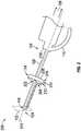
- FIG. 1shows an example endoscopic system 100.
- the system 100comprises an endoscopic device 104 comprising an elongate shaft 128, and a distal tip 116 which is inserted through an aperture 102.
- the endoscopic device 104is connected to a fluid pump 106 and a fluid reservoir 112 (such as a saline bag) by way of a first fluid line 108 that is coupled to a first fluid port 120.
- the fluid pump 106may be fluidly coupled to a separate fluid reservoir 112, and in alternate examples the fluid pump 106 may comprise a fluid reservoir.
- the fluid pump 106may in some embodiments be a peristaltic pump (as shown), a positive displacement pump, or a centrifugal pump, any of which may be employed to generate fluid inflow. In other embodiments, the fluid pump 106 may be omitted and the fluid reservoir 112 may be in direct fluid communication with the first fluid port 120 and/or a second fluid port 122.
- the second fluid port 122may be in communication with a fluid path such as a fluid outflow path.
- the second fluid line 110may be coupled to a suction mechanism such as a suction wall pump 118, which may be a stand-alone feature or which may be part of a unit that may include a plurality of other controls for power, display, and adjustment of rate of fluid flow.
- a suction mechanismsuch as a suction wall pump 118
- fluidmay leak from the aperture 102 along an outside surface of the elongate shaft 128 towards the proximal end 126 of the endoscopic device 104.
- a drip flangemay be employed to direct the fluid flow away from the proximal end 126 of the endoscopic device 104.
- the fluid flowis directed away from the proximal end 126 such that it does not touch the proximal end 126 of the endoscopic device 104.
- the distal end 124 of endoscopic device 104is inserted into an aperture 102 that may be a patient's cervix.
- the patient's cervix 102may expand circumferentially to accommodate the endoscopic device 104, and effectively create a seal.
- the drip flange 114is located on the elongate shaft 128 of the endoscopic device 104, and outside the body of the patient and is not in contact with the patient during the procedure. The drip flange 114 receives and redirects fluid away from the proximal end 126 when the fluid leaks out of the cervix 102 and down the outside surface of the elongate shaft 128.
- the drip flange 114may be permanently coupled to the elongate shaft 128 of the endoscopic device 104 or may be a disposable component.
- the drip flange 114may be coupled to the endoscopic device 104 between the proximal end 126 and the distal end 124 but is not in direct contact with the distal end 126.
- the drip flange114may be (1) formed as an integral part of the endoscopic device 104, (2) removably coupled to the endoscopic device 104, (3) permanently coupled to the endoscopic device 104, and/or (4) adjustable along the elongate sheath 128, or combinations thereof.
- the drip flange 114may be permanently coupled to the endoscopic device 104 in that it cannot be removed without being destroyed or destroying the endoscopic device 104 but where the drip flange 114 is adjustable along a portion of the elongate sheath 128. In another example, the drip flange 114 may be removably coupled to the endoscopic device 104 in and is removed without being destroyed and without destroying the endoscopic device 104.
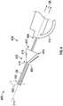
- FIG. 2is an elevated partial perspective view 200 of a tissue removal system not claimed and illustrates a partial view of the endoscopic device 104, and that the distal end 116 is inserted through the aperture 102.
- the endoscopic devicecomprises a central axis 214, the distal end 124, the distal tip 116, and the elongate shaft 128.
- the elongate shaft 128comprises the central axis 214, the distal tip 116, and a proximal end 216 of the elongate draft 128.
- the drip flange 114may be disposed along the elongate shaft 128 at a predetermined distance from the distal tip 116 and is not in contact with nor coupled to the proximal end 216 of the elongate shaft 128.
- the drip flange 114is positioned such that, when the endoscopic device is in use, the drip flange 114 does not form a seal with or restrict fluid from exiting the aperture 102.
- the drip flange 114comprises the central axis 214 shared with the endoscopic device 104, an interior surface that may comprise a coupling mechanism (not shown), a distal side 202, a proximal side 208, and a transition surface 212 comprising a smooth transition area extending radially from the proximal side 208 to the distal side 202.
- the componentmay be defined by a shape of a sphere, conical frustum, disc, pyramid, polygon, or combinations thereof.
- the drip flange 114may be formed as a monolithic piece with a sheath (not separately shown) of the endoscopic device 104. In an alternate embodiment, the drip flange 114 may be adjustably and/or removably coupled to an elongate shaft 128 of a sheath of the endoscopic device 104.
- the drip flange 114may be fabricated as a single piece or as a multiple-component piece comprising drains and/or sponges as discussed in detail herein.
- the surfaces corresponding to each of the proximal 208 and distal 202 sides of the drip flange 114may be flat, converse, or concave, or combinations thereof, where a flat surface is defined as perpendicular with respect to the central axis 214.
- FIG. 2further illustrates that the distal tip 124 is located above the proximal end 126, indicated by the arrows since FIG. 2 is a partial view.
- the fluid flow 204exits the endoscopic device 104 at a drip edge 210 of the drip flange, and does not contact the proximal end 216 of the elongate shaft 128, nor the proximal end 126 of the endoscopic device 104.
- fluidwhen fluid leaks from the aperture 102, it travels along at least a portion of the fluid path 204 along the elongate shaft 128 towards the drip flange 114.
- the distal side 202comprises a concave surface relative to a plane perpendicular to the central axis 214, the fluid collects in the drip flange 114 on the distal side and may drip along drip edge 210 and/or the transition surface 212.
- the fluiddrips from a point on the drip flange 114 and can then be captured to monitor fluid volume or disposed of in a receptacle (not shown).
- a second drip edge 218may exist at the boundary of the proximal side 208 of the drip flange 114.
- the second drip edge 218may be employed in various examples, when the transitional surface 212 is at an angle other than parallel to the central axis 214.
- FIGS. 3A and 3Bare magnified views of a drip flange 114.
- FIGS. 3A and 3Billustrate the drip flange 114 in the shape of a disc.
- the drip flange 114may comprise the drip edge 210, the distal side 202, the transition surface 212, the proximal side 208, the central axis 214, a through-hole or bore 302 defined by an interior surface 304.
- there may be mating features disposed on the interior surface 304 of the bore 302may permanently or removably couple to the elongate shaft of an endoscopic device.
- the position of the drip flangemay be adjustable along a length of the elongate shaft.
- the drip flangemay be formed as an integral part of the endoscopic device.
- the proximal side 208 and the distal side 202may be defined by surfaces that are perpendicular with respect to the central axis.
- the distal side 202 and/or the proximal surfacemay be concave or convex with respect to a reference line 306 perpendicular to the central axis 214.
- the drip flange 114may be coupled to an endoscopic device 104 when the drip flange 114 is telescoped over the endoscopic device, which may be an endoscope, a sheath, and/or an endoscope telescoped through a sheath.
- FIG. 4is a partial perspective view 400 of an endoscopic system not claimed.
- FIG. 4shows a partial view of the endoscopic device 104, and that the distal end 116 is inserted through the aperture 102.
- the endoscopic devicecomprises a central axis 214, the distal end 124, the distal tip 116, and the elongate shaft 128.
- the elongate shaft 128comprises the central axis 214, the distal tip 116, and a proximal end 216 of the elongate draft 128, and a drip flange 402 is coupled to the elongate shaft 128.
- the drip flange 402may be formed as a monolithic piece with the endoscopic device 104, or may be a component 402 that is adjustably and/or removably coupled to a length of an elongate shaft 128 of the endoscopic device 104.
- a drip flange 402 in the shape of a conical frustumis illustrated in FIG. 4 .
- the drip flange 402comprises the central axis 214 shared with the endoscopic device 104, an interior surface that may comprise a coupling mechanism (not shown), a distal end 410, a proximal end 412, and an outside surface 418 comprising a smooth transition area extending radially from the proximal end 412 to the distal end 410 and that may be referred to as the outside surface 418.
- a diameter of the distal end 410 of the drip flange 402is smaller than a diameter of the proximal end 412.
- FIG. 4further illustrates that the distal tip 124 is located above the proximal end 126, indicated by the arrows since FIG. 4 is a partial view.
- the fluid flow 404exits the endoscopic device 104 at the drip edge 414 of the drip flange 402, and does not contact the proximal end 406 of the elongate shaft 128, nor the proximal end 126 of the endoscopic device 104.
- the drip flange 402may be coupled to the elongate shaft 128 between the distal end 116 of the endoscopic device 104 and the proximal end 406 of the elongate shaft 128, and is not in contact with the proximal end 406.
- a diameter of the distal end 410 of the drip flange 402is smaller than a diameter of the proximal end 412.
- the drip flange 402is shaped similar a cone, with the distal end 410 positioned at, for example, a 45 degree angle to the elongate shaft 128 and the central axis 214.
- the drip flange 402may be coupled to endoscopic device 104 either permanently or removably, and may be reusable or disposable. As fluid leaks out of the aperture 102 and travels along the elongate shaft 128 of the endoscopic device 104, the fluid is redirected to travel down the outside surface 418 of the drip flange 402 and to the drip edge 414. It is appreciated that the drip edge 414 extends circumferentially around the drip flange 402.
- the fluidcan then be captured to monitor fluid volume or disposed of in a receptacle (not shown).
- the drip flange 402prevents leaking fluid from reaching the endoscope tubing 110 or attached equipment (not shown) towards the proximal end 126 of the endoscopic device 104.
- a sponge or absorbent featuremay be added to the drip flange 402 at the distal end 410, along the outside surface 418, and/or at the drip edge 414 to capture the leaking fluid.
- FIG. 5is a partial perspective view 500 of an endoscopic system and illustrates a partial view of the endoscopic device 104, and that the distal end 116 is inserted through the aperture 102.
- the endoscopic device 104comprises a central axis 214, the distal end 124, the distal tip 116, and the elongate shaft 128.
- the elongate shaft 128comprises the central axis 214, the distal tip 116, and a proximal end 216 of the elongate draft 128, and a drip flange 502 is coupled to the elongate shaft 128.
- the drip flange 502may be formed as a monolithic piece with the endoscopic device 104, or may be a component 502 that is adjustably and/or removably coupled to the elongate shaft 128 of a sheath of the endoscopic device 104.
- a drip flange 502 in the shape of a conical frustumis illustrated in FIG. 5 .
- the drip flange 502comprises the central axis 214 shared with the endoscopic device 104, an interior surface that may comprise a coupling mechanism (not shown), a distal end 506, a proximal end 510, and an outside surface 508 extending radially from the proximal end 510 to the distal end 506.
- a diameter of the distal end 506 of the drip flange 502is larger than a diameter of the proximal end 510.
- FIG. 5further illustrates that the distal tip 124 is located above the proximal end 126, the direction of which is indicated by the arrows since FIG. 5 is a partial view.
- the fluid flow 504exits the endoscopic device 104 at the drip edge 512 of the drip flange 502, and the fluid does not contact the proximal end 510 of the elongate shaft 128.
- the drip flange 502does not contact the proximal end 126 of the endoscopic device 104. It is appreciated that the drip edge 512 extends circumferentially around the drip flange 502.
- the fluid path 504As illustrated by the fluid path 504, as fluid leaks out of the aperture 102 and travels along the outside surface of the elongate shaft 128, the fluid is redirected to travel down the distal end 506 of the drip flange 502 and to the drip edge 512. In some examples, the fluid can then be captured to monitor fluid volume or disposed of in a receptacle (not shown).
- the drip flange 502prevents fluid from reaching the endoscope tubing 110 or attached equipment (not shown) towards the proximal end 126 of the endoscopic device 104.
- a sponge or other absorbent featuremay be added to the drip flange 502 at the distal end 506 and/or at the drip edge 512 to capture the leaking fluid.
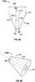
- FIG. 6Ais a cross-sectional view 600A of a conical frustum version of a drip flange.
- the drip flange 402 in FIG. 6Amay be similar to that in FIG. 4 .
- FIG. 6Aillustrates the drip flange 402, the central axis 214, a channel 602 extending from the proximal end 412 to the distal end 410, and an interior surface 604 of the channel 602.
- An interior diameter 606 of the channel 602may be the same as the diameter of the distal end 410, and an outer diameter 608 of the proximal end 412 is larger than the diameter of the distal end 410.
- the interior surface of the channel 602may comprise mating/coupling features (not pictured) configured to mate with an endoscopic device.
- the drip flange 402may be coupled to an endoscopic device when the drip flange 402 is telescoped over the endoscopic device, which may be in the form of an endoscope, a sheath, and/or an endoscope telescoped through a sheath.
- FIG. 6Bis a magnified perspective view 600B of a drip flange in the shape of a conical frustum.
- the drip flange 402 in FIG. 6Bmay be similar to that in FIG. 4 .
- FIG. 6Billustrates the drip flange 402, and illustrates the channel 602 that extends through the solid body of the drip flange 402.
- the drip flange 402may be coupled to an endoscopic device when the drip flange 402 is telescoped over the endoscopic device, which may be in the form of an endoscope, a sheath, and/or an endoscope telescoped through a sheath. It is appreciated that the discussion above with respect to the solid body and the coupling of the drip flange 402 may also be applied to the drip flange 502 discussed above.
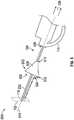
- FIG. 7is a partial perspective view of an endoscopic system 700 in accordance with the invention.
- FIG. 7illustrates a system 700 coupled to a tubing 708 that comprises a distal end 706 that captures, through pressure or otherwise, the fluid leaking (illustrated by fluid flow 710) from the patient and traveling down elongate shaft 128.
- the tubing 708comprises a flexible, rigid, or semi-rigid structure that extends through the drip flange 402 from the distal side 410 through to the proximal end 412.
- the tubing 708can be attached to the elongate shaft 128 and the drip flange 402.
- the fluidcan be directed to a receptacle (not shown) in order to monitor fluid flow or it can be disposed of as waste.
- a sponge or absorbent featuremay be added to the drip flange 402 to capture any leaking fluid that does not travel into the tubing 708.
- FIG. 8illustrates a method 800 of performing a surgical procedure.
- an endoscopic deviceis assembled.
- the endoscopic devicemay be assembled by (1) telescoping an endoscope into a sheath to form the endoscopic device and then telescoping a drip flange over the endoscopic device; (2) telescoping an endoscope into a sheath with a drip flange formed monolithically with the sheath; (3) telescoping the endoscope through the sheath, when the drip flange is one of permanently or removably coupled to the sheath prior to telescoping the endoscope; (4) telescoping the drip flange over the sheath; or (5) telescoping the drip flange over an endoscope.
- a distal tip of an endoscopic deviceis positioned to abut an aperture into an operative cavity, the endoscopic device comprises a central axis, a proximal end, a distal end, a distal tip, and an elongate shaft extending from the distal tip towards the proximal end.
- the distal tip of the endoscopic deviceis inserted through the aperture and fluid flow is initiated and/or established through the endoscopic device at block 808 for a surgical procedure.
- fluid flowing from the apertureis directed from the distal end of the endoscopic device along the elongate shaft and towards the drip flange and the drip edge of the drip flange.
- the distal tipis removed through the aperture and fluid flow is terminated at block 814.
- the drip flangemay be removed from the endoscopic device (uncoupled) at block 816 without compromising the functionality of the endoscopic device, and, may be either disposed of at block 818 or cleaned/sterilized/reused at block 820, at which point the method 800 may return to block 802 where the endoscopic device is re-assembled.
Landscapes
- Health & Medical Sciences (AREA)
- Life Sciences & Earth Sciences (AREA)
- Surgery (AREA)
- Biophysics (AREA)
- Biomedical Technology (AREA)
- Veterinary Medicine (AREA)
- Nuclear Medicine, Radiotherapy & Molecular Imaging (AREA)
- Optics & Photonics (AREA)
- Pathology (AREA)
- Radiology & Medical Imaging (AREA)
- Public Health (AREA)
- Engineering & Computer Science (AREA)
- Physics & Mathematics (AREA)
- Heart & Thoracic Surgery (AREA)
- Medical Informatics (AREA)
- Molecular Biology (AREA)
- Animal Behavior & Ethology (AREA)
- General Health & Medical Sciences (AREA)
- Orthopedic Medicine & Surgery (AREA)
- Physical Education & Sports Medicine (AREA)
- Gynecology & Obstetrics (AREA)
- Reproductive Health (AREA)
- Endoscopes (AREA)
Description
- Medical endoscopes are inserted into a patient either through an orifice, incision, or other entry point. In certain procedures that use an endoscope, for example, hysteroscopy, the endoscope is inserted into a cavity filled with patient or surgical fluids. During the procedure, fluid pressure may cause fluid to leak out of the cavity through openings, including the opening through which the endoscope is used. Leaking fluid may travel down the length of the endoscope and drip onto the physician or the floor, presenting a hazard.
US 2010/010299 describes a surgical system which drains fluid from a patient cavity inside the patient.US 2005/0192532 discloses a surgical system comprising a drip flange positioned outside the patient, but the drip flange does not drain fluid from the patient.- According to the invention there is provided a surgical system as recited in
claim 1 with preferred features set forth in the dependent claims. - For a detailed description of exemplary embodiments, reference will now be made to the accompanying drawings in which:
Figures 1 to 6 show examples useful for an understanding of the invention but not falling within the scope of the claims. FIG. 1 shows an endoscopic systemFIG. 2 is an elevation, partial perspective view of the endoscopic system offigure 1 .FIGS. 3A and 3B are magnified views of a drip flange.FIG. 4 is an elevation, partial perspective view of an endoscopic system.FIG. 5 is an elevation, partial perspective view of an endoscopic system.FIG. 6A is a cross-sectional view along the central axis of a drip flange.FIG. 6B is a perspective view of a drip flange.FIG. 7 is an elevation, partial perspective view of an endoscopic system according to the invention .FIG. 8 illustrates a method of performing a surgical procedure using a surgical system according to the invention.- Certain terms are used throughout the following description and claims to refer to particular system components. As one skilled in the art will appreciate, different companies may refer to a component by different names. This document does not intend to distinguish between components that differ in name but not function. In the following discussion and in the claims, the terms "including" and "comprising" are used in an openended fashion, and thus should be interpreted to mean "including, but not limited to...." Also, the term "couple" or "couples" is intended to mean either an indirect or direct connection. Thus, if a first device couples to a second device, that connection may be through a direct connection or through an indirect electrical connection via other devices and connections.
- "Endoscopic device" shall mean an endoscope alone, a sheath alone, or a combination device comprising an endoscope telescoped within a sheath.
- "Above," in relation to a fluid bag (e.g., saline bag) and a component, shall mean the fluid bag has a higher elevation than the recited component measured with respect to local gravity.
- "Drip flange" shall mean a component disposed on an outside surface of an elongate shaft of an endoscopic device where the drip flange defines an outer dimension greater than an outside diameter of the elongate shaft. For at least some orientations of the endoscopic device, the drip flange is configured to force fluid that encounters the drip flange to drip from or stream from the drip flange rather than run past the drip flange and back onto the outside surface of the elongate shaft downstream of the drip flange.
- "Removably coupled" shall mean a first component coupled to a second component such that first component can be decoupled from the second component without destroying or rendering the first or second components non-functional.
- "Monolithic," with respect to a drip flange, shall mean a drip flange that is formed as an integral part of an endoscopic device.
- "Drip edge" shall mean a portion of a drip flange that acts as a drip point for fluid.
- The following discussion is directed to various embodiments. Although one or more of these embodiments may be preferred, the embodiments disclosed should not be interpreted, or otherwise used, as limiting the scope of the disclosure, including the claims. In addition, one skilled in the art will understand that the following description has broad application, and the discussion of any embodiment is meant only to be exemplary of that embodiment, and not intended to intimate that the scope of the disclosure, including the claims, is limited to that embodiment.
- Medical endoscopes are often inserted into cavities filled with patient or surgical fluids. In an operative hysteroscopy, an endoscopic device is inserted into the patient's uterus to view and treat various pathologies. A space in which to navigate is created by injecting fluid at a pressure that causes the uterus to expand. This fluid is often circulated to clear debris during the procedure. Although this endoscopic procedure permits the surgeon to perform the procedure, the procedure creates risk for the patient since fluid may be absorbed into the bloodstream at high pressures and cause life-threatening physiological states. As a result, physicians routinely monitor the difference in the fluid flowing in and out of the patient throughout the procedure. Drapes are used to collect fluid which may be accidentally lost during the procedure to ensure an accurate fluid volume measurement.
- As an example, when an endoscopic device is inserted through a patient's cervix, the cervix expands circumferentially to accommodate the scope, effectively creating a seal. Depending on the pressure used, the diameter of the scope, and other factors, the fluid may leak between the scope and the cervix. In hysteroscopy, the scope is often positioned with its distal tip elevated, and the surgeon seated and holding the scope. As a result, leaked fluid often drips down the length of the scope and onto the surgeon, floor, or camera. This fluid leakage may lead to an inability to accurately monitor fluid in and out of the patient, and may interfere with the surgeon's vision if the camera becomes flooded. Further, in cases where leakage is difficult to prevent, drapes, absorbent pads, protective covers, and personal protective equipment are used to keep fluid from the floor, equipment, or operating room staff.
- At least in accordance with some embodiments, a drip flange comprising a drip edge is added to an endoscope to arrest or redirect the flow of fluid adhering to the outer surface of the endoscope. The drip flange prevents fluid from reaching tubing, electronics, attached equipment, or other locations where the fluid might negatively impact the patient, user, or procedure. The drip flange may be permanently, removably, or adjustably coupled to the endoscopic device. In some embodiments, the drip flange may be formed as an integral part of an endoscopic device.
- In an embodiment, the drip flange defines a conical frustum shape that defines a central axis, a proximal end, and a distal end, wherein an outer diameter of the proximal end is larger than an outer diameter of the endoscopic device. In an alternate embodiment, the drip flange defines a disc shape that defines a central axis, a proximal side, and a distal side, wherein an outer diameter of the proximal end of the drip flange mechanism is larger than an outer diameter of the endoscopic device. The disc-shaped drip flange may comprise a flat distal surface on the distal side relative to a plane perpendicular to the central axis. In alternate embodiments, disc-shaped drip flange may comprise a concave or convex distal surface on the distal side relative to a plane perpendicular to the central axis.
FIG. 1 shows an exampleendoscopic system 100. Thesystem 100 comprises anendoscopic device 104 comprising anelongate shaft 128, and adistal tip 116 which is inserted through anaperture 102. In the example, theendoscopic device 104 is connected to afluid pump 106 and a fluid reservoir 112 (such as a saline bag) by way of afirst fluid line 108 that is coupled to afirst fluid port 120. In various embodiments, thefluid pump 106 may be fluidly coupled to aseparate fluid reservoir 112, and in alternate examples thefluid pump 106 may comprise a fluid reservoir. Thefluid pump 106 may in some embodiments be a peristaltic pump (as shown), a positive displacement pump, or a centrifugal pump, any of which may be employed to generate fluid inflow. In other embodiments, thefluid pump 106 may be omitted and thefluid reservoir 112 may be in direct fluid communication with the firstfluid port 120 and/or a secondfluid port 122.- The second
fluid port 122 may be in communication with a fluid path such as a fluid outflow path. In the example embodiment, thesecond fluid line 110 may be coupled to a suction mechanism such as asuction wall pump 118, which may be a stand-alone feature or which may be part of a unit that may include a plurality of other controls for power, display, and adjustment of rate of fluid flow. During an operative procedure, fluid may leak from theaperture 102 along an outside surface of theelongate shaft 128 towards theproximal end 126 of theendoscopic device 104. In an effort to direct this fluid flow away from theproximal end 126, a drip flange may be employed to direct the fluid flow away from theproximal end 126 of theendoscopic device 104. In this example, the fluid flow is directed away from theproximal end 126 such that it does not touch theproximal end 126 of theendoscopic device 104. - In a hysteroscopy procedure, the
distal end 124 ofendoscopic device 104 is inserted into anaperture 102 that may be a patient's cervix. The patient'scervix 102 may expand circumferentially to accommodate theendoscopic device 104, and effectively create a seal. Thedrip flange 114 is located on theelongate shaft 128 of theendoscopic device 104, and outside the body of the patient and is not in contact with the patient during the procedure. Thedrip flange 114 receives and redirects fluid away from theproximal end 126 when the fluid leaks out of thecervix 102 and down the outside surface of theelongate shaft 128. - In alternate examples, the
drip flange 114 may be permanently coupled to theelongate shaft 128 of theendoscopic device 104 or may be a disposable component. Thedrip flange 114 may be coupled to theendoscopic device 104 between theproximal end 126 and thedistal end 124 but is not in direct contact with thedistal end 126. In various embodiments, the drip flange114 may be (1) formed as an integral part of theendoscopic device 104, (2) removably coupled to theendoscopic device 104, (3) permanently coupled to theendoscopic device 104, and/or (4) adjustable along theelongate sheath 128, or combinations thereof. In one example, thedrip flange 114 may be permanently coupled to theendoscopic device 104 in that it cannot be removed without being destroyed or destroying theendoscopic device 104 but where thedrip flange 114 is adjustable along a portion of theelongate sheath 128. In another example, thedrip flange 114 may be removably coupled to theendoscopic device 104 in and is removed without being destroyed and without destroying theendoscopic device 104. FIG. 2 is an elevatedpartial perspective view 200 of a tissue removal system not claimed and illustrates a partial view of theendoscopic device 104, and that thedistal end 116 is inserted through theaperture 102. In an embodiment, the endoscopic device comprises acentral axis 214, thedistal end 124, thedistal tip 116, and theelongate shaft 128. Theelongate shaft 128 comprises thecentral axis 214, thedistal tip 116, and aproximal end 216 of theelongate draft 128. Thedrip flange 114 may be disposed along theelongate shaft 128 at a predetermined distance from thedistal tip 116 and is not in contact with nor coupled to theproximal end 216 of theelongate shaft 128. Thedrip flange 114 is positioned such that, when the endoscopic device is in use, thedrip flange 114 does not form a seal with or restrict fluid from exiting theaperture 102.- The
drip flange 114 comprises thecentral axis 214 shared with theendoscopic device 104, an interior surface that may comprise a coupling mechanism (not shown), adistal side 202, aproximal side 208, and atransition surface 212 comprising a smooth transition area extending radially from theproximal side 208 to thedistal side 202. In some embodiments, where a distal end diameter is less than a proximal end diameter, the component may be defined by a shape of a sphere, conical frustum, disc, pyramid, polygon, or combinations thereof. - The
drip flange 114 may be formed as a monolithic piece with a sheath (not separately shown) of theendoscopic device 104. In an alternate embodiment, thedrip flange 114 may be adjustably and/or removably coupled to anelongate shaft 128 of a sheath of theendoscopic device 104. Thedrip flange 114 may be fabricated as a single piece or as a multiple-component piece comprising drains and/or sponges as discussed in detail herein. - In an example
disc drip flange 114 illustrated inFIG. 2 , the surfaces corresponding to each of the proximal 208 and distal 202 sides of thedrip flange 114 may be flat, converse, or concave, or combinations thereof, where a flat surface is defined as perpendicular with respect to thecentral axis 214.FIG. 2 further illustrates that thedistal tip 124 is located above theproximal end 126, indicated by the arrows sinceFIG. 2 is a partial view. There is afluid flow 204 established along an outside surface of theelongate shaft 128 from thedistal end 124 towards thedistal side 202 of thedrip flange 114. Thefluid flow 204 exits theendoscopic device 104 at adrip edge 210 of the drip flange, and does not contact theproximal end 216 of theelongate shaft 128, nor theproximal end 126 of theendoscopic device 104. - In an example, when fluid leaks from the
aperture 102, it travels along at least a portion of thefluid path 204 along theelongate shaft 128 towards thedrip flange 114. In an example, if thedistal side 202 comprises a concave surface relative to a plane perpendicular to thecentral axis 214, the fluid collects in thedrip flange 114 on the distal side and may drip alongdrip edge 210 and/or thetransition surface 212. In an example, the fluid drips from a point on thedrip flange 114 and can then be captured to monitor fluid volume or disposed of in a receptacle (not shown). In an alternate example, asecond drip edge 218 may exist at the boundary of theproximal side 208 of thedrip flange 114. Thesecond drip edge 218 may be employed in various examples, when thetransitional surface 212 is at an angle other than parallel to thecentral axis 214. FIGS. 3A and 3B are magnified views of adrip flange 114.FIGS. 3A and 3B illustrate thedrip flange 114 in the shape of a disc. Thedrip flange 114 may comprise thedrip edge 210, thedistal side 202, thetransition surface 212, theproximal side 208, thecentral axis 214, a through-hole or bore 302 defined by aninterior surface 304. In an embodiment, there may be mating features disposed on theinterior surface 304 of thebore 302 may permanently or removably couple to the elongate shaft of an endoscopic device. In some examples, the position of the drip flange may be adjustable along a length of the elongate shaft. In alternate examples, the drip flange may be formed as an integral part of the endoscopic device.- In an example, at least one of the
proximal side 208 and thedistal side 202 may be defined by surfaces that are perpendicular with respect to the central axis. In alternate examples (not shown), thedistal side 202 and/or the proximal surface may be concave or convex with respect to areference line 306 perpendicular to thecentral axis 214. In various embodiments, thedrip flange 114 may be coupled to anendoscopic device 104 when thedrip flange 114 is telescoped over the endoscopic device, which may be an endoscope, a sheath, and/or an endoscope telescoped through a sheath. FIG. 4 is apartial perspective view 400 of an endoscopic system not claimed. In particular,FIG. 4 shows a partial view of theendoscopic device 104, and that thedistal end 116 is inserted through theaperture 102. In an example, the endoscopic device comprises acentral axis 214, thedistal end 124, thedistal tip 116, and theelongate shaft 128. Theelongate shaft 128 comprises thecentral axis 214, thedistal tip 116, and aproximal end 216 of theelongate draft 128, and adrip flange 402 is coupled to theelongate shaft 128.- The
drip flange 402 may be formed as a monolithic piece with theendoscopic device 104, or may be acomponent 402 that is adjustably and/or removably coupled to a length of anelongate shaft 128 of theendoscopic device 104. Adrip flange 402 in the shape of a conical frustum is illustrated inFIG. 4 . Thedrip flange 402 comprises thecentral axis 214 shared with theendoscopic device 104, an interior surface that may comprise a coupling mechanism (not shown), adistal end 410, aproximal end 412, and anoutside surface 418 comprising a smooth transition area extending radially from theproximal end 412 to thedistal end 410 and that may be referred to as theoutside surface 418. In an embodiment, a diameter of thedistal end 410 of thedrip flange 402 is smaller than a diameter of theproximal end 412. FIG. 4 further illustrates that thedistal tip 124 is located above theproximal end 126, indicated by the arrows sinceFIG. 4 is a partial view. There is afluid flow 404 established along an outside surface of theelongate shaft 128 from thedistal end 124 towards thedistal end 410 of thedrip flange 402 along theoutside surface 418. Thefluid flow 404 exits theendoscopic device 104 at thedrip edge 414 of thedrip flange 402, and does not contact theproximal end 406 of theelongate shaft 128, nor theproximal end 126 of theendoscopic device 104. Thedrip flange 402 may be coupled to theelongate shaft 128 between thedistal end 116 of theendoscopic device 104 and theproximal end 406 of theelongate shaft 128, and is not in contact with theproximal end 406. In an embodiment, a diameter of thedistal end 410 of thedrip flange 402 is smaller than a diameter of theproximal end 412.- In
FIG. 4 , thedrip flange 402 is shaped similar a cone, with thedistal end 410 positioned at, for example, a 45 degree angle to theelongate shaft 128 and thecentral axis 214. Thedrip flange 402 may be coupled toendoscopic device 104 either permanently or removably, and may be reusable or disposable. As fluid leaks out of theaperture 102 and travels along theelongate shaft 128 of theendoscopic device 104, the fluid is redirected to travel down theoutside surface 418 of thedrip flange 402 and to thedrip edge 414. It is appreciated that thedrip edge 414 extends circumferentially around thedrip flange 402. The fluid can then be captured to monitor fluid volume or disposed of in a receptacle (not shown). Thedrip flange 402 prevents leaking fluid from reaching theendoscope tubing 110 or attached equipment (not shown) towards theproximal end 126 of theendoscopic device 104. In an alternative embodiment, a sponge or absorbent feature may be added to thedrip flange 402 at thedistal end 410, along theoutside surface 418, and/or at thedrip edge 414 to capture the leaking fluid. FIG. 5 is apartial perspective view 500 of an endoscopic system and illustrates a partial view of theendoscopic device 104, and that thedistal end 116 is inserted through theaperture 102. In an example, theendoscopic device 104 comprises acentral axis 214, thedistal end 124, thedistal tip 116, and theelongate shaft 128. Theelongate shaft 128 comprises thecentral axis 214, thedistal tip 116, and aproximal end 216 of theelongate draft 128, and adrip flange 502 is coupled to theelongate shaft 128.- The
drip flange 502 may be formed as a monolithic piece with theendoscopic device 104, or may be acomponent 502 that is adjustably and/or removably coupled to theelongate shaft 128 of a sheath of theendoscopic device 104. Adrip flange 502 in the shape of a conical frustum is illustrated inFIG. 5 . Thedrip flange 502 comprises thecentral axis 214 shared with theendoscopic device 104, an interior surface that may comprise a coupling mechanism (not shown), adistal end 506, aproximal end 510, and anoutside surface 508 extending radially from theproximal end 510 to thedistal end 506. In an example, a diameter of thedistal end 506 of thedrip flange 502 is larger than a diameter of theproximal end 510. FIG. 5 further illustrates that thedistal tip 124 is located above theproximal end 126, the direction of which is indicated by the arrows sinceFIG. 5 is a partial view. There is afluid flow 504 established along an outside surface of theelongate shaft 128 from thedistal end 124 along thedistal end 506 of thedrip flange 502. Thefluid flow 504 exits theendoscopic device 104 at thedrip edge 512 of thedrip flange 502, and the fluid does not contact theproximal end 510 of theelongate shaft 128. In an embodiment, thedrip flange 502 does not contact theproximal end 126 of theendoscopic device 104. It is appreciated that thedrip edge 512 extends circumferentially around thedrip flange 502.- As illustrated by the
fluid path 504, as fluid leaks out of theaperture 102 and travels along the outside surface of theelongate shaft 128, the fluid is redirected to travel down thedistal end 506 of thedrip flange 502 and to thedrip edge 512. In some examples, the fluid can then be captured to monitor fluid volume or disposed of in a receptacle (not shown). Thedrip flange 502 prevents fluid from reaching theendoscope tubing 110 or attached equipment (not shown) towards theproximal end 126 of theendoscopic device 104. In an alternative example, a sponge or other absorbent feature may be added to thedrip flange 502 at thedistal end 506 and/or at thedrip edge 512 to capture the leaking fluid. FIG. 6A is across-sectional view 600A of a conical frustum version of a drip flange. Thedrip flange 402 inFIG. 6A may be similar to that inFIG. 4 .FIG. 6A illustrates thedrip flange 402, thecentral axis 214, achannel 602 extending from theproximal end 412 to thedistal end 410, and aninterior surface 604 of thechannel 602. Aninterior diameter 606 of thechannel 602 may be the same as the diameter of thedistal end 410, and anouter diameter 608 of theproximal end 412 is larger than the diameter of thedistal end 410. In some embodiments, the interior surface of thechannel 602 may comprise mating/coupling features (not pictured) configured to mate with an endoscopic device. In various embodiments, thedrip flange 402 may be coupled to an endoscopic device when thedrip flange 402 is telescoped over the endoscopic device, which may be in the form of an endoscope, a sheath, and/or an endoscope telescoped through a sheath.FIG. 6B is a magnifiedperspective view 600B of a drip flange in the shape of a conical frustum. Thedrip flange 402 inFIG. 6B may be similar to that inFIG. 4 .FIG. 6B illustrates thedrip flange 402, and illustrates thechannel 602 that extends through the solid body of thedrip flange 402. In various examples, thedrip flange 402 may be coupled to an endoscopic device when thedrip flange 402 is telescoped over the endoscopic device, which may be in the form of an endoscope, a sheath, and/or an endoscope telescoped through a sheath. It is appreciated that the discussion above with respect to the solid body and the coupling of thedrip flange 402 may also be applied to thedrip flange 502 discussed above.FIG. 7 is a partial perspective view of anendoscopic system 700 in accordance with the invention.FIG. 7 illustrates asystem 700 coupled to atubing 708 that comprises adistal end 706 that captures, through pressure or otherwise, the fluid leaking (illustrated by fluid flow 710) from the patient and traveling downelongate shaft 128. Thetubing 708 comprises a flexible, rigid, or semi-rigid structure that extends through thedrip flange 402 from thedistal side 410 through to theproximal end 412. Thetubing 708 can be attached to theelongate shaft 128 and thedrip flange 402. Once the fluid enters thetubing 708 at thedistal side 410 at 706, the fluid can be directed to a receptacle (not shown) in order to monitor fluid flow or it can be disposed of as waste. In an alternative embodiment, a sponge or absorbent feature may be added to thedrip flange 402 to capture any leaking fluid that does not travel into thetubing 708.FIG. 8 illustrates amethod 800 of performing a surgical procedure. Atblock 802, an endoscopic device is assembled. The endoscopic device may be assembled by (1) telescoping an endoscope into a sheath to form the endoscopic device and then telescoping a drip flange over the endoscopic device; (2) telescoping an endoscope into a sheath with a drip flange formed monolithically with the sheath; (3) telescoping the endoscope through the sheath, when the drip flange is one of permanently or removably coupled to the sheath prior to telescoping the endoscope; (4) telescoping the drip flange over the sheath; or (5) telescoping the drip flange over an endoscope.- At
block 804, a distal tip of an endoscopic device is positioned to abut an aperture into an operative cavity, the endoscopic device comprises a central axis, a proximal end, a distal end, a distal tip, and an elongate shaft extending from the distal tip towards the proximal end. Atblock 806, the distal tip of the endoscopic device is inserted through the aperture and fluid flow is initiated and/or established through the endoscopic device atblock 808 for a surgical procedure. Atblock 810, fluid flowing from the aperture is directed from the distal end of the endoscopic device along the elongate shaft and towards the drip flange and the drip edge of the drip flange. Atblock 812, the distal tip is removed through the aperture and fluid flow is terminated atblock 814. - In some embodiments, the drip flange may be removed from the endoscopic device (uncoupled) at
block 816 without compromising the functionality of the endoscopic device, and, may be either disposed of atblock 818 or cleaned/sterilized/reused atblock 820, at which point themethod 800 may return to block 802 where the endoscopic device is re-assembled. - The above discussion is meant to be illustrative of the principles and various embodiments of the present invention. Numerous variations and modifications will become apparent to those skilled in the art once the above disclosure is fully appreciated. For example, various combinations of perforations types, number, geometry, and size may be employed in different embodiments and may be employed along varying lengths of the endoscopic device. It is intended that the following claims be interpreted to embrace all such variations and modifications.
Claims (6)
- A surgical system (700) comprising:an endoscopic device (104) comprising a central axis, a proximal end (126), a distal end (124), and an elongate shaft (128);a fluid port (122) defined on the proximal end (126) for fluid outflow;an inflow port(120) defined on the proximal end (126) for fluid inflow; anda drip flange (402) defined on the elongate shaft (128) and comprising a distal side (410) and a proximal side (412),characterised in that the surgical system (700) further comprises:
a tubing (708) extending through the drip flange (402) from the distal side (410) through to the proximal side (412), wherein the tubing (708) comprises a distal opening (706) for capturing fluid (710) leaking from the patient and traveling down the elongate shaft (128) - The system of claim 1, wherein the endoscopic device comprises an endoscope telescoped in the sheath.
- The system of claim 2, wherein the drip flange (402) is a monolithic piece with the sheath.
- The system of claim 2 or 3, wherein the drip flange (402) is removably coupled to an outside surface of the sheath.
- The system of any of claims 1 to 4, wherein the drip flange (402) defines a conical frustum shape, wherein the conical frustum comprises a first diameter at a distal end and a second diameter at a proximal end, wherein the first diameter is smaller than the second diameter.
- The system of any of claims 1 to 5, further comprising:a view port defined on the proximal end of the endoscopic device; anda visualization conduit that extends through an optical channel of the endoscopic device (104) and into the view port.
Applications Claiming Priority (2)
| Application Number | Priority Date | Filing Date | Title |
|---|---|---|---|
| US201562180972P | 2015-06-17 | 2015-06-17 | |
| PCT/US2016/037222WO2016205126A1 (en) | 2015-06-17 | 2016-06-13 | Endoscopic device with drip flange and methods of use thereof for an operative procedure |
Publications (2)
| Publication Number | Publication Date |
|---|---|
| EP3310241A1 EP3310241A1 (en) | 2018-04-25 |
| EP3310241B1true EP3310241B1 (en) | 2020-08-05 |
Family
ID=56369188
Family Applications (1)
| Application Number | Title | Priority Date | Filing Date |
|---|---|---|---|
| EP16736303.5ANot-in-forceEP3310241B1 (en) | 2015-06-17 | 2016-06-13 | Endoscopic device with drip flange |
Country Status (3)
| Country | Link |
|---|---|
| US (2) | US10842350B2 (en) |
| EP (1) | EP3310241B1 (en) |
| WO (1) | WO2016205126A1 (en) |
Families Citing this family (2)
| Publication number | Priority date | Publication date | Assignee | Title |
|---|---|---|---|---|
| EP3310241B1 (en) | 2015-06-17 | 2020-08-05 | Covidien LP | Endoscopic device with drip flange |
| US11547782B2 (en)* | 2020-01-31 | 2023-01-10 | Covidien Lp | Fluid collecting sheaths for endoscopic devices and systems |
Citations (1)
| Publication number | Priority date | Publication date | Assignee | Title |
|---|---|---|---|---|
| US20100010299A1 (en)* | 2008-07-14 | 2010-01-14 | Ethicon Endo-Surgery, Inc. | Endoscopic translumenal articulatable steerable overtube |
Family Cites Families (289)
| Publication number | Priority date | Publication date | Assignee | Title |
|---|---|---|---|---|
| US1585934A (en) | 1923-12-29 | 1926-05-25 | Radium Emanation Corp | Diagnostic needle |
| US1831786A (en) | 1926-04-20 | 1931-11-10 | California Packing Corp | Fruit peeling apparatus |
| US1666332A (en) | 1927-05-23 | 1928-04-17 | Edwin W Hirsch | Bladder-pressure-testing apparatus |
| US2224464A (en)* | 1936-09-03 | 1940-12-10 | Firm Georg Wolf G M B H | Thoracoscope |
| US2708437A (en)* | 1952-03-31 | 1955-05-17 | Elizabeth Painter Hutchins | Surgical instrument |
| US3297022A (en) | 1963-09-27 | 1967-01-10 | American Cystoscope Makers Inc | Endoscope |
| GB1288091A (en) | 1969-01-03 | 1972-09-06 | ||
| DE7107645U (en) | 1971-03-02 | 1971-05-27 | Storz K | ENDOSCOPE IN PARTICULAR CYSTOSCOPE |
| US3734099A (en) | 1971-04-07 | 1973-05-22 | H Bender | Powered surgical cutter |
| US3812855A (en) | 1971-12-15 | 1974-05-28 | Surgical Design Corp | System for controlling fluid and suction pressure |
| US3945375A (en) | 1972-04-04 | 1976-03-23 | Surgical Design Corporation | Rotatable surgical instrument |
| US3850162A (en) | 1972-07-03 | 1974-11-26 | J Iglesias | Endoscope with continuous irrigation |
| US3835842A (en) | 1972-07-03 | 1974-09-17 | J Iglesias | Endoscope with continuous irrigation |
| US3996921A (en) | 1975-04-17 | 1976-12-14 | Pharmacia Inc. | Method and apparatus for endoscopy |
| US4011869A (en) | 1975-08-01 | 1977-03-15 | David Kopf Instruments | Tubular cutting instrument |
| US3995619A (en) | 1975-10-14 | 1976-12-07 | Glatzer Stephen G | Combination subcutaneous suture remover, biopsy sampler and syringe |
| US3980252A (en) | 1975-10-31 | 1976-09-14 | John T. Hepburn Limited | Wire rope spooling mechanism |
| US4146405A (en) | 1977-01-19 | 1979-03-27 | Henry Timmer | Unitary dishwasher |
| US4108182A (en) | 1977-02-16 | 1978-08-22 | Concept Inc. | Reciprocation vitreous suction cutter head |
| US4198958A (en) | 1977-06-01 | 1980-04-22 | Olympus Optical Co., Ltd. | Flexible cap and instrument seal for a suction control device in an endoscope |
| US4414962A (en) | 1977-06-15 | 1983-11-15 | Carson Robert W | Operating arthroscope |
| US4203444A (en) | 1977-11-07 | 1980-05-20 | Dyonics, Inc. | Surgical instrument suitable for closed surgery such as of the knee |
| FR2415451A1 (en) | 1978-01-26 | 1979-08-24 | Bernard Parent | PANORAMIC VISION DIAGNOSTIC HYSTEROSCOPE |
| US4246902A (en) | 1978-03-10 | 1981-01-27 | Miguel Martinez | Surgical cutting instrument |
| US4210146A (en) | 1978-06-01 | 1980-07-01 | Anton Banko | Surgical instrument with flexible blade |
| US4316465A (en) | 1979-03-30 | 1982-02-23 | Dotson Robert S Jun | Ophthalmic handpiece with pneumatically operated cutter |
| US4294234A (en) | 1979-06-22 | 1981-10-13 | Olympus Optical Co., Ltd. | Endoscope |
| US4247180A (en) | 1979-08-06 | 1981-01-27 | Polaroid Corporation | Card motion picture apparatus with adjustable barrel cam |
| US4261346A (en) | 1979-11-23 | 1981-04-14 | Richard Wolf Medical Instruments Corporation | Endoscopes |
| DE2949278C2 (en) | 1979-12-07 | 1982-05-27 | Rainer Dipl.-Ing. 8261 Neuötting Kortländer | Device for knife conization of the cervix |
| US4369768A (en) | 1980-07-30 | 1983-01-25 | Marko Vukovic | Arthroscope |
| US4493698A (en) | 1980-11-03 | 1985-01-15 | Cooper Medical Devices | Method of performing opthalmic surgery utilizing a linear intra-ocular suction device |
| US4392485A (en) | 1981-02-17 | 1983-07-12 | Richard Wolf Gmbh | Endoscope |
| GB2093353B (en) | 1981-02-25 | 1984-09-19 | Dyonics Inc | A surgical instrument for arthroscopic arthroplasty |
| US4517977A (en) | 1981-07-24 | 1985-05-21 | Unisearch Limited | Co-axial tube surgical infusion/suction cutter tip |
| US4449538A (en) | 1982-01-25 | 1984-05-22 | John Corbitt | Medical-electronic body fluid accounting system |
| DE3206381C2 (en) | 1982-02-22 | 1986-07-10 | Olympus Winter & Ibe GmbH, 2000 Hamburg | Percutaneous nephroscope |
| EP0095891B2 (en) | 1982-05-28 | 1988-11-02 | Rhp Group Plc | Devices for converting rotary movement into linear movement |
| IL66047A0 (en) | 1982-06-13 | 1982-09-30 | Univ Ben Gurion | Method and device for measuring intrauterine pressure during labour |
| US5421819A (en) | 1992-08-12 | 1995-06-06 | Vidamed, Inc. | Medical probe device |
| US5435805A (en) | 1992-08-12 | 1995-07-25 | Vidamed, Inc. | Medical probe device with optical viewing capability |
| GR70998B (en) | 1982-11-03 | 1983-03-30 | Kollia Nik Georgio | |
| JPS59200644A (en) | 1983-04-27 | 1984-11-14 | オリンパス光学工業株式会社 | Surgical incision instrument |
| US4606330A (en) | 1983-08-09 | 1986-08-19 | Richard Wolf Gmbh | Device for disintegrating stones in bodily cavities or ducts |
| US4601290A (en) | 1983-10-11 | 1986-07-22 | Cabot Medical Corporation | Surgical instrument for cutting body tissue from a body area having a restricted space |
| DE3569876D1 (en) | 1984-02-20 | 1989-06-08 | Olympus Optical Co | Endoscopic ovum picker instruments |
| JPS60243625A (en) | 1984-05-18 | 1985-12-03 | Fuji Photo Optical Co Ltd | Connecting system of endoscope |
| US4630598A (en) | 1984-05-29 | 1986-12-23 | Richard Wolf Gmbh | Uretero-renoscope |
| DE3443337A1 (en) | 1984-11-28 | 1986-05-28 | Richard Wolf Gmbh, 7134 Knittlingen | INSTRUMENT FOR THE EXAMINATION AND TREATMENT OF BODY CHANNELS |
| US4567880A (en) | 1984-12-26 | 1986-02-04 | Goodman Tobias M | Endoscopic device with three-way valve |
| US4971034A (en) | 1985-01-16 | 1990-11-20 | Asahi Kogaku Kogyo Kabushiki Kaisha | Body cavity pressure adjusting device for endoscope and laser medical treatment apparatus including body cavity pressure adjusting device |
| US4649919A (en) | 1985-01-23 | 1987-03-17 | Precision Surgical Instruments, Inc. | Surgical instrument |
| US4756309A (en) | 1985-02-14 | 1988-07-12 | Sachse Hans Ernst | Endoscope for removal of tissue |
| US4644952A (en) | 1985-02-19 | 1987-02-24 | Palm Beach Medical Engineering, Inc. | Surgical operating instrument |
| DE3601453A1 (en) | 1985-02-25 | 1986-09-04 | Hans E. Prof. Dr.Med. Sachse | Endoscope for the removal of tissue |
| US4624243A (en)* | 1985-04-08 | 1986-11-25 | American Hospital Supply Corp. | Endoscope having a reusable eyepiece and a disposable distal section |
| JPS61259637A (en) | 1985-05-15 | 1986-11-17 | オリンパス光学工業株式会社 | Endoscope apparatus |
| JPS62105698A (en) | 1985-11-05 | 1987-05-16 | ソニー株式会社 | Printer |
| DE3615694A1 (en) | 1986-05-09 | 1987-11-12 | Winter & Ibe Olympus | Percutaneous nephroscope with safety wire |
| US4950278A (en) | 1986-08-06 | 1990-08-21 | Sachse Hans E | Endoscope for removal of tissue |
| US4756304A (en)* | 1986-10-08 | 1988-07-12 | Watanabe Robert S | Arthroscopic video camera system |
| US4749376A (en) | 1986-10-24 | 1988-06-07 | Intravascular Surgical Instruments, Inc. | Reciprocating working head catheter |
| US5312430A (en) | 1986-12-09 | 1994-05-17 | Rosenbluth Robert F | Balloon dilation catheter |
| US4867157A (en) | 1987-08-13 | 1989-09-19 | Baxter Travenol Laboratories, Inc. | Surgical cutting instrument |
| US4850354A (en) | 1987-08-13 | 1989-07-25 | Baxter Travenol Laboratories, Inc. | Surgical cutting instrument |
| US4819635A (en) | 1987-09-18 | 1989-04-11 | Henry Shapiro | Tubular microsurgery cutting apparatus |
| US4844064A (en) | 1987-09-30 | 1989-07-04 | Baxter Travenol Laboratories, Inc. | Surgical cutting instrument with end and side openings |
| US4986827A (en) | 1987-11-05 | 1991-01-22 | Nestle S.A. | Surgical cutting instrument with reciprocating inner cutter |
| FR2625428A1 (en) | 1988-01-05 | 1989-07-07 | Sinergy Sa | MULTIFUNCTIONAL OPERATIVE COELIOSCOPY DEVICE FOR PERFORMING DIFFERENT OPERATIVE GESTURES WITH INTRODUCTION OF INSTRUMENTS |
| DE3805368C1 (en) | 1988-02-17 | 1989-08-24 | Peter P. Dipl.-Ing. Wiest | |
| US4955882A (en) | 1988-03-30 | 1990-09-11 | Hakky Said I | Laser resectoscope with mechanical and laser cutting means |
| US5027792A (en) | 1989-03-17 | 1991-07-02 | Percutaneous Technologies, Inc. | Endoscopic revision hip surgery device |
| US5116868A (en) | 1989-05-03 | 1992-05-26 | The Johns Hopkins University | Effective ophthalmic irrigation solution |
| JP2787471B2 (en) | 1989-07-04 | 1998-08-20 | 旭光学工業株式会社 | Endoscope sheath device |
| US5226910A (en) | 1989-07-05 | 1993-07-13 | Kabushiki Kaisha Topcon | Surgical cutter |
| US5106364A (en) | 1989-07-07 | 1992-04-21 | Kabushiki Kaisha Topcon | Surgical cutter |
| US4998527A (en) | 1989-07-27 | 1991-03-12 | Percutaneous Technologies Inc. | Endoscopic abdominal, urological, and gynecological tissue removing device |
| US5226909A (en) | 1989-09-12 | 1993-07-13 | Devices For Vascular Intervention, Inc. | Atherectomy device having helical blade and blade guide |
| US5112299A (en) | 1989-10-25 | 1992-05-12 | Hall Surgical Division Of Zimmer, Inc. | Arthroscopic surgical apparatus and method |
| US5163433A (en) | 1989-11-01 | 1992-11-17 | Olympus Optical Co., Ltd. | Ultrasound type treatment apparatus |
| US5409013A (en) | 1989-11-06 | 1995-04-25 | Mectra Labs, Inc. | Tissue removal assembly |
| US5037386A (en) | 1989-11-17 | 1991-08-06 | Minnesota Mining And Manufacturing Company | Pressure sensing scope cannula |
| US5176677A (en) | 1989-11-17 | 1993-01-05 | Sonokinetics Group | Endoscopic ultrasonic rotary electro-cauterizing aspirator |
| US4940061A (en) | 1989-11-27 | 1990-07-10 | Ingress Technologies, Inc. | Biopsy instrument |
| US5152744A (en) | 1990-02-07 | 1992-10-06 | Smith & Nephew Dyonics | Surgical instrument |
| US5169397A (en) | 1990-02-08 | 1992-12-08 | Olympus Optical Co., Ltd. | Medical instrument |
| US5007917A (en) | 1990-03-08 | 1991-04-16 | Stryker Corporation | Single blade cutter for arthroscopic surgery |
| EP0448857A1 (en) | 1990-03-27 | 1991-10-02 | Jong-Khing Huang | An apparatus of a spinning type of resectoscope for prostatectomy |
| US5275609A (en) | 1990-06-22 | 1994-01-04 | Vance Products Incorporated | Surgical cutting instrument |
| US5269785A (en) | 1990-06-28 | 1993-12-14 | Bonutti Peter M | Apparatus and method for tissue removal |
| US5911699A (en) | 1990-07-17 | 1999-06-15 | Aziz Yehia Anis | Removal of tissue |
| US6007513A (en) | 1990-07-17 | 1999-12-28 | Aziz Yehia Anis | Removal of tissue |
| DE4038398A1 (en) | 1990-12-01 | 1992-06-04 | Schubert Werner | Medical equipment for min. invasive operation e.g. for removal of tumour - introduces knife on long handle through cylinder or tube adjusted into pathological tissue |
| US5158553A (en) | 1990-12-26 | 1992-10-27 | Cardiopulmonics | Rotatably actuated constricting catheter valve |
| EP0566694A1 (en) | 1991-01-09 | 1993-10-27 | EndoMedix Corporation | Method and device for intracorporeal liquidization of tissue and/or intracorporeal fragmentation of calculi during endoscopic surgical procedures |
| US5409453A (en) | 1992-08-12 | 1995-04-25 | Vidamed, Inc. | Steerable medical probe with stylets |
| US5125910A (en) | 1991-02-19 | 1992-06-30 | Dexide, Inc. | Surgical endoscopic suction/irrigation cannula assembly |
| US5586973A (en) | 1991-04-22 | 1996-12-24 | C & D Biomedical S.A. | Method and device for controlled irrigation and suctioning of a liquid clarificant during endoscopic surgery |
| US5490819A (en) | 1991-08-05 | 1996-02-13 | United States Surgical Corporation | Articulating endoscopic surgical apparatus |
| US5391180A (en) | 1991-08-05 | 1995-02-21 | United States Surgical Corporation | Articulating endoscopic surgical apparatus |
| ATE190850T1 (en) | 1991-08-21 | 2000-04-15 | Smith & Nephew Inc | FLUID TREATMENT SYSTEM |
| US5288290A (en) | 1991-09-25 | 1994-02-22 | Alcon Surgical, Inc. | Multi-ported valve assembly |
| US5449356A (en) | 1991-10-18 | 1995-09-12 | Birtcher Medical Systems, Inc. | Multifunctional probe for minimally invasive surgery |
| US5195541A (en) | 1991-10-18 | 1993-03-23 | Obenchain Theodore G | Method of performing laparoscopic lumbar discectomy |
| US5244459A (en) | 1992-01-28 | 1993-09-14 | Hill Raymond R | Suction irrigator endoscope |
| MX9300607A (en) | 1992-02-06 | 1993-10-01 | American Med Syst | APPARATUS AND METHOD FOR INTERSTITIAL TREATMENT. |
| US5242404A (en) | 1992-02-12 | 1993-09-07 | American Cyanamid Company | Aspiration control system |
| US5269798A (en) | 1992-02-19 | 1993-12-14 | Linvatec Corporation | Surgical cutting instrument with movable, inner and outer tubular members |
| US5254117A (en) | 1992-03-17 | 1993-10-19 | Alton Dean Medical | Multi-functional endoscopic probe apparatus |
| US5350390A (en) | 1992-03-25 | 1994-09-27 | Arieh Sher | Device for removal of intraluminal occlusions |
| US5672945A (en) | 1992-04-13 | 1997-09-30 | Smith & Nephew Endoscopy, Inc. | Motor controlled surgical system and method having self clearing motor control |
| US5270622A (en) | 1992-04-13 | 1993-12-14 | Smith & Nephew Dyonics, Inc. | Brushless motor control system |
| US5602449A (en) | 1992-04-13 | 1997-02-11 | Smith & Nephew Endoscopy, Inc. | Motor controlled surgical system and method having positional control |
| US5563481A (en) | 1992-04-13 | 1996-10-08 | Smith & Nephew Endoscopy, Inc. | Brushless motor |
| US5320091A (en) | 1992-04-27 | 1994-06-14 | Circon Corporation | Continuous flow hysteroscope |
| US5556378A (en) | 1992-06-17 | 1996-09-17 | Storz; Karl | Device for irrigation of body cavities |
| CA2101293C (en) | 1992-08-05 | 2004-06-29 | David A. Nicholas | Articulating endoscopic surgical apparatus |
| US5312399A (en) | 1992-09-29 | 1994-05-17 | Hakky Said I | Laser resectoscope with mechanical cutting means and laser coagulating means |
| SE501876C2 (en) | 1992-11-12 | 1995-06-12 | Christer Dahlstrand Ab | Motorised arrangement for endoscopic removal of prostate tissue - includes tubular body, with hand grip, channels for inspection, lighting, and input for flushing fluid for removal of fluid and cut-away tissue |
| US5304118A (en) | 1992-12-16 | 1994-04-19 | Trese Michael T | Method for performing a vitrectomy on an eye |
| US5347992A (en) | 1993-01-22 | 1994-09-20 | Karl Storz Endoscopy America, Inc. | Single axis three way selector valve for endoscopes |
| US5392765A (en) | 1993-02-11 | 1995-02-28 | Circon Corporation | Continuous flow cystoscope |
| US5403276A (en) | 1993-02-16 | 1995-04-04 | Danek Medical, Inc. | Apparatus for minimally invasive tissue removal |
| CA2121861A1 (en) | 1993-04-23 | 1994-10-24 | William D. Fox | Mechanical morcellator |
| AU6667494A (en) | 1993-05-07 | 1994-12-12 | Danek Medical, Inc. | Surgical cutting instrument |
| US5364395A (en) | 1993-05-14 | 1994-11-15 | West Jr Hugh S | Arthroscopic surgical instrument with cauterizing capability |
| ATE141481T1 (en) | 1993-06-16 | 1996-09-15 | White Spot Ag | DEVICE FOR INTRODUCING FIBRIN GLUE INTO A STITCH CHANNEL |
| US5395313A (en) | 1993-08-13 | 1995-03-07 | Naves; Neil H. | Reciprocating arthroscopic shaver |
| US5575756A (en) | 1993-08-16 | 1996-11-19 | Olympus Optical Co., Ltd. | Endoscope apparatus |
| US5336237A (en) | 1993-08-25 | 1994-08-09 | Devices For Vascular Intervention, Inc. | Removal of tissue from within a body cavity |
| US5425376A (en) | 1993-09-08 | 1995-06-20 | Sofamor Danek Properties, Inc. | Method and apparatus for obtaining a biopsy sample |
| US5957832A (en) | 1993-10-08 | 1999-09-28 | Heartport, Inc. | Stereoscopic percutaneous visualization system |
| US5374253A (en) | 1993-10-12 | 1994-12-20 | Burns, Sr.; Charles N. | Medical instrument with automatic shut-off valve |
| US5456689A (en) | 1993-10-13 | 1995-10-10 | Arnold J. Kresch | Method and device for tissue resection |
| WO1995010982A1 (en) | 1993-10-20 | 1995-04-27 | Correa Marco Aurelio Moura De | Surgical instrument to perform subcutaneous endoscopic surgery |
| US5443476A (en) | 1993-11-12 | 1995-08-22 | Shapiro; Henry | Microsurgical scissor apparatus with rotary cutting blade |
| DE4340056A1 (en) | 1993-11-24 | 1995-06-01 | Delma Elektro Med App | Laparoscopic surgical device |
| US5490860A (en) | 1993-12-08 | 1996-02-13 | Sofamor Danek Properties, Inc. | Portable power cutting tool |
| EP0662572B1 (en) | 1994-01-11 | 1998-04-01 | SAMJOO MACHINERY Co., Ltd. | Rotary motion/constant velocity linear reciprocating motion conversion device and hydraulic system using the same |
| US6359200B1 (en) | 1994-01-13 | 2002-03-19 | Dekalb Genetics Corp. | Inbred corn plant 8M116 |
| US5411513A (en) | 1994-02-24 | 1995-05-02 | Danek Medical, Inc. | Transmission mechanism for a surgical cutting instrument |
| US5483951A (en) | 1994-02-25 | 1996-01-16 | Vision-Sciences, Inc. | Working channels for a disposable sheath for an endoscope |
| US5456673A (en) | 1994-03-23 | 1995-10-10 | Stryker Corporation | Locking cannula for endoscopic surgery |
| US5526822A (en) | 1994-03-24 | 1996-06-18 | Biopsys Medical, Inc. | Method and apparatus for automated biopsy and collection of soft tissue |
| US5649547A (en) | 1994-03-24 | 1997-07-22 | Biopsys Medical, Inc. | Methods and devices for automated biopsy and collection of soft tissue |
| US5492537A (en) | 1994-05-03 | 1996-02-20 | Aquintel, Inc. | Surgical fluid monitor |
| US5709670A (en) | 1994-05-03 | 1998-01-20 | Aquintel, Inc. | Surgical fluid and tissue loss monitor |
| US5702420A (en) | 1994-06-14 | 1997-12-30 | Anthony R. Sterling And Tri-Tech, Inc. | Motorized suction punch forceps |
| US5669921A (en) | 1994-07-19 | 1997-09-23 | Linvatec Corporation | Endoscopic shaver blade window positioning system |
| JP2802244B2 (en) | 1994-08-29 | 1998-09-24 | オリンパス光学工業株式会社 | Endoscope sheath |
| US5498258A (en) | 1994-09-13 | 1996-03-12 | Hakky; Said I. | Laser resectoscope with laser induced mechanical cutting means |
| US5569284A (en) | 1994-09-23 | 1996-10-29 | United States Surgical Corporation | Morcellator |
| US6032673A (en) | 1994-10-13 | 2000-03-07 | Femrx, Inc. | Methods and devices for tissue removal |
| AU3955295A (en) | 1994-10-13 | 1996-05-06 | Femrx | Method and device for tissue resection |
| WO1997017027A1 (en) | 1995-11-08 | 1997-05-15 | Femrx, Inc. | Electrosurgical device having rollers for ablating and segmenting of tissues |
| AU701424B2 (en) | 1994-10-24 | 1999-01-28 | Smith & Nephew, Inc. | Hollow surgical cutter with apertured flutes |
| DE4440035C2 (en) | 1994-11-10 | 1998-08-06 | Wolf Gmbh Richard | Morcellating instrument |
| US5603332A (en) | 1995-01-27 | 1997-02-18 | Technological Services, Inc. | Method and apparatus for monitoring the systemic absorption of irrigation fluid during operative hysteroscopy |
| US5601583A (en) | 1995-02-15 | 1997-02-11 | Smith & Nephew Endoscopy Inc. | Surgical instrument |
| US5676497A (en) | 1995-02-27 | 1997-10-14 | Kim; Young S. | Power drill-saw with simultaneous rotation and reciprocation action |
| DE29503478U1 (en) | 1995-03-02 | 1995-04-20 | Richard Wolf Gmbh, 75438 Knittlingen | endoscope |
| WO1996026676A1 (en) | 1995-03-02 | 1996-09-06 | Helfgott & Karas, P.C. | Uterine tissue collector |
| ATE270854T1 (en) | 1995-03-31 | 2004-07-15 | Boston Scient Ltd | BIOPSY SAMPLER |
| US5873886A (en) | 1995-04-04 | 1999-02-23 | United States Surgical Corporation | Surgical cutting apparatus |
| US5569254A (en) | 1995-04-12 | 1996-10-29 | Midas Rex Pneumatic Tools, Inc. | Surgical resection tool having an irrigation, lighting, suction and vision attachment |
| US5591187A (en) | 1995-07-14 | 1997-01-07 | Dekel; Moshe | Laparoscopic tissue retrieval device and method |
| AUPN541595A0 (en) | 1995-09-13 | 1995-10-12 | Queensland University Of Technology | A surgical device |
| US5749885A (en) | 1995-10-02 | 1998-05-12 | Smith & Nephew, Inc. | Surgical instrument with embedded coding element |
| US5772634A (en) | 1995-10-06 | 1998-06-30 | Zimmer, Inc. | Device for limiting distention fluid pressure during hysteroscopy |
| DE19633124B4 (en) | 1995-11-20 | 2009-06-10 | Storz Endoskop Gmbh | Scraping or cutting instrument |
| PT805652E (en) | 1995-11-27 | 2003-02-28 | C C D Lab | DEVICE FOR THE COLLECTION OF UTERINE MUCOSES |
| US5807282A (en) | 1995-12-28 | 1998-09-15 | Mayo Foundation For Medical Education And Research | Endometrial tissue curette and method |
| US5916229A (en) | 1996-02-07 | 1999-06-29 | Evans; Donald | Rotating needle biopsy device and method |
| US5749889A (en) | 1996-02-13 | 1998-05-12 | Imagyn Medical, Inc. | Method and apparatus for performing biopsy |
| US5709698A (en) | 1996-02-26 | 1998-01-20 | Linvatec Corporation | Irrigating/aspirating shaver blade assembly |
| WO1997034534A1 (en) | 1996-03-18 | 1997-09-25 | Femrx, Inc. | Method and device for tissue vaporization and extraction |
| WO1997035522A1 (en) | 1996-03-25 | 1997-10-02 | Safe Conduct Ab | Device for extraction of tissue or the like |
| DE19706751A1 (en) | 1996-03-27 | 1997-10-02 | Valleylab Inc | Electrosurgical device for removing tissue in body areas |
| US5766199A (en) | 1996-04-10 | 1998-06-16 | Linvatec Corporation | Endoscopic shaver blade with resilient cutting edges |
| BE1010290A3 (en) | 1996-05-10 | 1998-05-05 | Saturnus Ag | TISSUE-morcellator. |
| US5741286A (en) | 1996-06-07 | 1998-04-21 | Symbiosis Corporation | Laparoscopic instrument kit including a plurality of rigid tubes |
| US6258111B1 (en) | 1997-10-03 | 2001-07-10 | Scieran Technologies, Inc. | Apparatus and method for performing ophthalmic procedures |
| US5833643A (en) | 1996-06-07 | 1998-11-10 | Scieran Technologies, Inc. | Apparatus for performing ophthalmic procedures |
| US6113594A (en) | 1996-07-02 | 2000-09-05 | Ethicon, Inc. | Systems, methods and apparatus for performing resection/ablation in a conductive medium |
| US5857995A (en) | 1996-08-15 | 1999-01-12 | Surgical Dynamics, Inc. | Multiple bladed surgical cutting device removably connected to a rotary drive element |
| US6017354A (en) | 1996-08-15 | 2000-01-25 | Stryker Corporation | Integrated system for powered surgical tools |
| US5769794A (en) | 1996-09-04 | 1998-06-23 | Smith & Nephew Endoscopy, Inc | Tissue retrieval bag and method for removing cancerous tissue |
| SE509513C2 (en) | 1996-09-16 | 1999-02-08 | Endolink Ab | Tools for use in surgical procedures on the uterus and cervix |
| US5807240A (en) | 1996-09-24 | 1998-09-15 | Circon Corporation | Continuous flow endoscope with enlarged outflow channel |
| US6090094A (en) | 1996-10-04 | 2000-07-18 | Microgroup, Inc. | Ball valves and uses thereof including endoscopic surgical instruments |
| US5814009A (en) | 1996-10-11 | 1998-09-29 | Cabot Technology Corporation | Fluid management system and replaceable tubing assembly therefor |
| US5730752A (en) | 1996-10-29 | 1998-03-24 | Femrx, Inc. | Tubular surgical cutters having aspiration flow control ports |
| US5741287A (en) | 1996-11-01 | 1998-04-21 | Femrx, Inc. | Surgical tubular cutter having a tapering cutting chamber |
| US5899915A (en) | 1996-12-02 | 1999-05-04 | Angiotrax, Inc. | Apparatus and method for intraoperatively performing surgery |
| US5810770A (en) | 1996-12-13 | 1998-09-22 | Stryker Corporation | Fluid management pump system for surgical procedures |
| US5913867A (en) | 1996-12-23 | 1999-06-22 | Smith & Nephew, Inc. | Surgical instrument |
| US5947990A (en) | 1997-02-24 | 1999-09-07 | Smith & Nephew, Inc. | Endoscopic surgical instrument |
| US6156049A (en) | 1997-04-11 | 2000-12-05 | Coherent Inc. | Method and apparatus for transurethral resection of the prostate |
| US6024751A (en) | 1997-04-11 | 2000-02-15 | Coherent Inc. | Method and apparatus for transurethral resection of the prostate |
| US5925055A (en) | 1997-06-23 | 1999-07-20 | Medelex, Inc | Multimodal rotary abrasion and acoustic ablation catheter |
| US6086542A (en) | 1997-07-01 | 2000-07-11 | Linvatec Corporation | Pressure sensing input/output scope sheath |
| US6149633A (en) | 1997-07-15 | 2000-11-21 | Surgin Surgical Instrumentation, Inc. | Flow control system and method for endoscopic surgeries |
| AU731398B2 (en) | 1997-07-18 | 2001-03-29 | Gyrus Medical Limited | An electrosurgical instrument |
| WO1999003409A1 (en) | 1997-07-18 | 1999-01-28 | Gyrus Medical Limited | An electrosurgical instrument |
| US6039748A (en) | 1997-08-05 | 2000-03-21 | Femrx, Inc. | Disposable laparoscopic morcellator |
| NL1006944C2 (en) | 1997-09-04 | 1999-03-11 | Mark Hans Emanuel | Surgical endoscopic cutting device. |
| US6004320A (en) | 1997-09-19 | 1999-12-21 | Oratec Interventions, Inc. | Clip on electrocauterizing sheath for orthopedic shave devices |
| US6102895A (en) | 1997-09-30 | 2000-08-15 | Cortella; Julian M. | Digital fluid delivery and aspiration apparatus with mechanical de-amplifier |
| DE19751632C1 (en) | 1997-11-21 | 1999-09-16 | Aesculap Ag & Co Kg | Hysteroscope for examination of cervical canals |
| WO1999039648A1 (en) | 1998-02-10 | 1999-08-12 | Dubrul William R | Entrapping apparatus and method for use |
| US6331166B1 (en) | 1998-03-03 | 2001-12-18 | Senorx, Inc. | Breast biopsy system and method |
| US6659105B2 (en) | 1998-02-26 | 2003-12-09 | Senorx, Inc. | Tissue specimen isolating and damaging device and method |
| US6344026B1 (en) | 1998-04-08 | 2002-02-05 | Senorx, Inc. | Tissue specimen encapsulation device and method thereof |
| US6159160A (en) | 1998-03-26 | 2000-12-12 | Ethicon, Inc. | System and method for controlled infusion and pressure monitoring |
| US6156043A (en) | 1998-05-26 | 2000-12-05 | Krahn; Henry P. | Soft tissue morsellator |
| US6224603B1 (en) | 1998-06-09 | 2001-05-01 | Nuvasive, Inc. | Transiliac approach to entering a patient's intervertebral space |
| US6132448A (en) | 1998-06-19 | 2000-10-17 | Stryker Corporation | Endoscopic irrigated bur |
| US5911722A (en) | 1998-07-23 | 1999-06-15 | Millenium Devices Llc | Leban/Gordon surgical hand driver |
| US6068641A (en) | 1998-08-25 | 2000-05-30 | Linvatec Corporation | Irrigated burr |
| US6136014A (en) | 1998-09-01 | 2000-10-24 | Vivant Medical, Inc. | Percutaneous tissue removal device |
| US6245084B1 (en) | 1998-10-20 | 2001-06-12 | Promex, Inc. | System for controlling a motor driven surgical cutting instrument |
| US6494892B1 (en) | 1998-10-20 | 2002-12-17 | Suros Surgical Systems, Inc. | Disposable hub for a surgical cutting instrument |
| US6632182B1 (en) | 1998-10-23 | 2003-10-14 | The Trustees Of Columbia University In The City Of New York | Multiple bit, multiple specimen endoscopic biopsy forceps |
| JP3448228B2 (en) | 1998-11-30 | 2003-09-22 | 富士写真光機株式会社 | Endoscope insertion guide tube |
| US6244228B1 (en) | 1998-12-11 | 2001-06-12 | Damon Kuhn | Rotary-to-linear motion converter and use thereof |
| US6119973A (en) | 1999-01-29 | 2000-09-19 | Owens Corning Fiberglas Technology, Inc. | Reciprocating apparatus and cam follower for winding a package |
| WO2000048505A1 (en) | 1999-02-18 | 2000-08-24 | Karl Storz Gmbh & Co. Kg | Endoscope |
| US20020165427A1 (en) | 1999-03-15 | 2002-11-07 | Daniel Yachia | Intravesicular device |
| US6120147A (en) | 1999-03-17 | 2000-09-19 | Dutch Ophthalmic Research Center International Bv | Vitrectomy lens |
| US6159209A (en) | 1999-03-18 | 2000-12-12 | Canox International Ltd. | Automatic resectoscope |
| US6402701B1 (en) | 1999-03-23 | 2002-06-11 | Fna Concepts, Llc | Biopsy needle instrument |
| US6120462A (en) | 1999-03-31 | 2000-09-19 | Ethicon Endo-Surgery, Inc. | Control method for an automated surgical biopsy device |
| US6066153A (en) | 1999-03-31 | 2000-05-23 | Lev; Avigdor | Device and method for resecting body tissues |
| US6358200B1 (en) | 1999-09-01 | 2002-03-19 | Circon Corporation | Continuous flow resectoscope with single tube sheath assembly and rotatable connection |
| JP2001075416A (en) | 1999-09-03 | 2001-03-23 | Konica Corp | Image forming device |
| US6368324B1 (en) | 1999-09-24 | 2002-04-09 | Medtronic Xomed, Inc. | Powered surgical handpiece assemblies and handpiece adapter assemblies |
| SE9904223D0 (en) | 1999-11-19 | 1999-11-19 | Safe Conduct Ab | Working Device |
| JP2001149374A (en) | 1999-11-29 | 2001-06-05 | Asahi Optical Co Ltd | Endoscope tissue collection tool |
| AU2001236731A1 (en) | 2000-02-10 | 2001-08-20 | Harmonia Medical Technologies Inc. | Transurethral volume reduction of the prostate (tuvor) |
| US6626827B1 (en) | 2000-09-01 | 2003-09-30 | C. R. Bard, Inc. | Fluid management assembly for use in endoscopic procedures |
| WO2001095810A2 (en) | 2000-06-14 | 2001-12-20 | Harmonia Medical Technologies, Inc. | Surgical instrument and method of using the same |
| US6712773B1 (en) | 2000-09-11 | 2004-03-30 | Tyco Healthcare Group Lp | Biopsy system |
| WO2002069808A2 (en) | 2000-11-06 | 2002-09-12 | Suros Surgical Systems, Inc. | Biopsy apparatus |
| US20030050603A1 (en) | 2001-09-12 | 2003-03-13 | Todd Erik F. | Cannula that provides bi-directional fluid flow that is regulated by a single valve |
| US7226459B2 (en) | 2001-10-26 | 2007-06-05 | Smith & Nephew, Inc. | Reciprocating rotary arthroscopic surgical instrument |
| US7510563B2 (en) | 2001-10-26 | 2009-03-31 | Smith & Nephew, Inc. | Reciprocating rotary arthroscopic surgical instrument |
| DE10164384A1 (en) | 2001-12-28 | 2003-07-17 | Wolf Gmbh Richard | Hysteroscope with alternating shaft system |
| JP4056760B2 (en) | 2002-02-22 | 2008-03-05 | ペンタックス株式会社 | Endoscope suction switching mechanism |
| US8109885B2 (en) | 2002-03-19 | 2012-02-07 | C. R. Bard, Inc. | Biopsy device for removing tissue specimens using a vacuum |
| DE10310614B4 (en) | 2002-03-25 | 2007-10-11 | Richard Wolf Gmbh | resectoscope |
| US6790173B2 (en) | 2002-06-13 | 2004-09-14 | Usgi Medical, Inc. | Shape lockable apparatus and method for advancing an instrument through unsupported anatomy |
| JP4754474B2 (en) | 2003-02-25 | 2011-08-24 | エシコン・エンド−サージェリィ・インコーポレイテッド | Biopsy device with variable speed cutter |
| US7473220B2 (en)* | 2003-08-04 | 2009-01-06 | Medcanica, Inc. | Surgical port device |
| US7150713B2 (en) | 2003-10-16 | 2006-12-19 | Smith & Nephew, Inc. | Endoscopic device |
| DE10358279A1 (en) | 2003-12-11 | 2005-07-14 | Karl Storz Gmbh & Co. Kg | Medical instrument for cutting biological and especially human tissue |
| US7435214B2 (en)* | 2004-01-29 | 2008-10-14 | Cannuflow, Inc. | Atraumatic arthroscopic instrument sheath |
| US7445596B2 (en)* | 2004-01-29 | 2008-11-04 | Cannuflow, Inc. | Atraumatic arthroscopic instrument sheath |
| US7500947B2 (en)* | 2004-01-29 | 2009-03-10 | Cannonflow, Inc. | Atraumatic arthroscopic instrument sheath |
| US7413542B2 (en) | 2004-01-29 | 2008-08-19 | Cannuflow, Inc. | Atraumatic arthroscopic instrument sheath |
| US20050228417A1 (en) | 2004-03-26 | 2005-10-13 | Teitelbaum George P | Devices and methods for removing a matter from a body cavity of a patient |
| US8062214B2 (en) | 2004-08-27 | 2011-11-22 | Smith & Nephew, Inc. | Tissue resecting system |
| US7806871B2 (en) | 2005-05-09 | 2010-10-05 | Boston Scientific Scimed, Inc. | Method and device for tissue removal and for delivery of a therapeutic agent or bulking agent |
| US20060251581A1 (en) | 2005-05-09 | 2006-11-09 | Mcintyre Jon T | Method for treatment of uterine fibroid tumors |
| US8932208B2 (en) | 2005-05-26 | 2015-01-13 | Maquet Cardiovascular Llc | Apparatus and methods for performing minimally-invasive surgical procedures |
| DE202005008569U1 (en) | 2005-06-01 | 2005-09-08 | Polydiagnost Gmbh | Endoscopic instrument, comprising specifically arranged optical device, lighting device, and rinsing duct |
| US20060293559A1 (en)* | 2005-06-24 | 2006-12-28 | Grice George D Iii | Disposable scope cleaner and method of using same |
| US20070173736A1 (en) | 2005-10-07 | 2007-07-26 | Femspec Llc | Apparatus and methods for endometrial biopsies |
| US8678999B2 (en) | 2006-09-11 | 2014-03-25 | Karl Storz Endovision, Inc. | System and method for a hysteroscope with integrated instruments |
| US7763033B2 (en) | 2006-10-18 | 2010-07-27 | Interlace Medical, Inc. | System and methods for preventing intravasation during intrauterine procedures |
| US20080108871A1 (en)* | 2006-11-06 | 2008-05-08 | Mohr Catherine J | Vacuum stabilized overtube for endoscopic surgery |
| US8025656B2 (en) | 2006-11-07 | 2011-09-27 | Hologic, Inc. | Methods, systems and devices for performing gynecological procedures |
| US9392935B2 (en) | 2006-11-07 | 2016-07-19 | Hologic, Inc. | Methods for performing a medical procedure |
| US20080262308A1 (en) | 2007-02-27 | 2008-10-23 | Percutaneaus Systems, Inc. | Method and system for performing continuous flow endoscopy |
| WO2008124650A1 (en) | 2007-04-06 | 2008-10-16 | Interlace Medical, Inc. | Method, system and device for tissue removal |
| US9259233B2 (en) | 2007-04-06 | 2016-02-16 | Hologic, Inc. | Method and device for distending a gynecological cavity |
| US8951274B2 (en) | 2007-04-06 | 2015-02-10 | Hologic, Inc. | Methods of high rate, low profile tissue removal |
| US9095366B2 (en) | 2007-04-06 | 2015-08-04 | Hologic, Inc. | Tissue cutter with differential hardness |
| US20110166419A1 (en) | 2008-06-27 | 2011-07-07 | Matthias Reif | Endoscope having a shaft tube and optic |
| WO2010036721A2 (en) | 2008-09-24 | 2010-04-01 | Interlace Medical, Inc. | Systems, methods and devices for using a flowable medium for distending a hollow organ |
| US9572921B2 (en) | 2008-12-17 | 2017-02-21 | Smith & Nephew, Inc. | Cartridge assembly |
| EP2498668A4 (en) | 2009-11-13 | 2013-08-07 | Hologic Inc | Access system with removable outflow channel |
| US8465421B2 (en) | 2009-12-14 | 2013-06-18 | C2Cure Inc. | Endoscope with an improved working channel |
| CN101797147B (en)* | 2010-01-21 | 2011-09-14 | 广州宝胆医疗器械科技有限公司 | Soft-hard son-mother hysteroscope and oviductlens systems |
| GB2479176B (en)* | 2010-03-31 | 2015-12-23 | Gyrus Medical Ltd | Surgical instrument |
| EP2596738B1 (en) | 2010-09-10 | 2014-09-03 | Olympus Medical Systems Corp. | Endoscope |
| US9155454B2 (en) | 2010-09-28 | 2015-10-13 | Smith & Nephew, Inc. | Hysteroscopic system |
| US9060760B2 (en) | 2011-08-18 | 2015-06-23 | Hologic, Inc. | Tissue removal system |
| KR101980314B1 (en) | 2012-06-28 | 2019-05-20 | 에스케이하이닉스 주식회사 | Memory device and operation method of the same |
| EP3310241B1 (en) | 2015-06-17 | 2020-08-05 | Covidien LP | Endoscopic device with drip flange |
- 2016
- 2016-06-13EPEP16736303.5Apatent/EP3310241B1/ennot_activeNot-in-force
- 2016-06-13WOPCT/US2016/037222patent/WO2016205126A1/ennot_activeCeased
- 2016-06-13USUS15/574,421patent/US10842350B2/enactiveActive
- 2020
- 2020-11-23USUS17/101,057patent/US11659977B2/enactiveActive
Patent Citations (1)
| Publication number | Priority date | Publication date | Assignee | Title |
|---|---|---|---|---|
| US20100010299A1 (en)* | 2008-07-14 | 2010-01-14 | Ethicon Endo-Surgery, Inc. | Endoscopic translumenal articulatable steerable overtube |
Also Published As
| Publication number | Publication date |
|---|---|
| US10842350B2 (en) | 2020-11-24 |
| US11659977B2 (en) | 2023-05-30 |
| US20210068622A1 (en) | 2021-03-11 |
| WO2016205126A1 (en) | 2016-12-22 |
| EP3310241A1 (en) | 2018-04-25 |
| US20180132702A1 (en) | 2018-05-17 |
Similar Documents
| Publication | Publication Date | Title |
|---|---|---|
| US10631717B2 (en) | Endoscope sheath arm | |
| JP6438015B2 (en) | Deformation type cleaning / suction device | |
| EP2988653B1 (en) | Endoscope lens cleaning device | |
| US11937783B2 (en) | Systems and methods for intraoperative surgical scope cleaning | |
| US11659977B2 (en) | Endoscopic device with drip flange and methods of use thereof for an operative procedure | |
| JP7158950B2 (en) | Endoscope aids, endoscopes, endoscope aids and endoscopes | |
| KR20160082968A (en) | Ophthalmic lubrication system and associated apparatus, systems, and methods | |
| JP3204344U (en) | Suitable for application of methods for keeping the reflective surface of a mirror with a handle for medical or dental testing clean during use by an manipulated air flow, improved to a more easily sterilizable of the handle mirror Configuration | |
| CN108366712B (en) | Endoscopic system including a droplet retention feature | |
| US20200383555A1 (en) | Systems and methods for generating a fluid bearing for an operative procedure | |
| JP2018175755A (en) | Device for removing intracerebral hematoma | |
| WO2019240170A1 (en) | Rigid endoscope cover and endoscope unit | |
| EP2574272A1 (en) | Endoscope forceps plug | |
| CN204562076U (en) | Nasopharyngeal endoscope | |
| US20210379270A1 (en) | Suction de-clogger system and method | |
| US20220361740A1 (en) | Methods and apparatus for a cleaning sheath for an endoscope | |
| CN210784469U (en) | An all-round anal retractor with suction device | |
| WO2017132126A1 (en) | Access device having a fluid pathway and methods of using the same | |
| US11779695B2 (en) | Instrument used in surgery and irrigating of the instrument | |
| KR20140127950A (en) | Endoscope apparatus for operation | |
| JP2020058671A (en) | Device for removal of intracerebral hematoma |
Legal Events
| Date | Code | Title | Description |
|---|---|---|---|
| STAA | Information on the status of an ep patent application or granted ep patent | Free format text:STATUS: THE INTERNATIONAL PUBLICATION HAS BEEN MADE | |
| PUAI | Public reference made under article 153(3) epc to a published international application that has entered the european phase | Free format text:ORIGINAL CODE: 0009012 | |
| STAA | Information on the status of an ep patent application or granted ep patent | Free format text:STATUS: REQUEST FOR EXAMINATION WAS MADE | |
| 17P | Request for examination filed | Effective date:20171215 | |
| AK | Designated contracting states | Kind code of ref document:A1 Designated state(s):AL AT BE BG CH CY CZ DE DK EE ES FI FR GB GR HR HU IE IS IT LI LT LU LV MC MK MT NL NO PL PT RO RS SE SI SK SM TR | |
| AX | Request for extension of the european patent | Extension state:BA ME | |
| STAA | Information on the status of an ep patent application or granted ep patent | Free format text:STATUS: EXAMINATION IS IN PROGRESS | |
| DAV | Request for validation of the european patent (deleted) | ||
| DAX | Request for extension of the european patent (deleted) | ||
| 17Q | First examination report despatched | Effective date:20180920 | |
| GRAP | Despatch of communication of intention to grant a patent | Free format text:ORIGINAL CODE: EPIDOSNIGR1 | |
| STAA | Information on the status of an ep patent application or granted ep patent | Free format text:STATUS: GRANT OF PATENT IS INTENDED | |
| INTG | Intention to grant announced | Effective date:20200310 | |
| GRAS | Grant fee paid | Free format text:ORIGINAL CODE: EPIDOSNIGR3 | |
| GRAA | (expected) grant | Free format text:ORIGINAL CODE: 0009210 | |
| STAA | Information on the status of an ep patent application or granted ep patent | Free format text:STATUS: THE PATENT HAS BEEN GRANTED | |
| AK | Designated contracting states | Kind code of ref document:B1 Designated state(s):AL AT BE BG CH CY CZ DE DK EE ES FI FR GB GR HR HU IE IS IT LI LT LU LV MC MK MT NL NO PL PT RO RS SE SI SK SM TR | |
| REG | Reference to a national code | Ref country code:GB Ref legal event code:FG4D | |
| REG | Reference to a national code | Ref country code:CH Ref legal event code:EP | |
| REG | Reference to a national code | Ref country code:AT Ref legal event code:REF Ref document number:1297544 Country of ref document:AT Kind code of ref document:T Effective date:20200815 | |
| REG | Reference to a national code | Ref country code:DE Ref legal event code:R096 Ref document number:602016041367 Country of ref document:DE | |
| REG | Reference to a national code | Ref country code:IE Ref legal event code:FG4D | |
| REG | Reference to a national code | Ref country code:LT Ref legal event code:MG4D | |
| REG | Reference to a national code | Ref country code:NL Ref legal event code:MP Effective date:20200805 | |
| REG | Reference to a national code | Ref country code:AT Ref legal event code:MK05 Ref document number:1297544 Country of ref document:AT Kind code of ref document:T Effective date:20200805 | |
| PG25 | Lapsed in a contracting state [announced via postgrant information from national office to epo] | Ref country code:LT Free format text:LAPSE BECAUSE OF FAILURE TO SUBMIT A TRANSLATION OF THE DESCRIPTION OR TO PAY THE FEE WITHIN THE PRESCRIBED TIME-LIMIT Effective date:20200805 Ref country code:FI Free format text:LAPSE BECAUSE OF FAILURE TO SUBMIT A TRANSLATION OF THE DESCRIPTION OR TO PAY THE FEE WITHIN THE PRESCRIBED TIME-LIMIT Effective date:20200805 Ref country code:SE Free format text:LAPSE BECAUSE OF FAILURE TO SUBMIT A TRANSLATION OF THE DESCRIPTION OR TO PAY THE FEE WITHIN THE PRESCRIBED TIME-LIMIT Effective date:20200805 Ref country code:HR Free format text:LAPSE BECAUSE OF FAILURE TO SUBMIT A TRANSLATION OF THE DESCRIPTION OR TO PAY THE FEE WITHIN THE PRESCRIBED TIME-LIMIT Effective date:20200805 Ref country code:PT Free format text:LAPSE BECAUSE OF FAILURE TO SUBMIT A TRANSLATION OF THE DESCRIPTION OR TO PAY THE FEE WITHIN THE PRESCRIBED TIME-LIMIT Effective date:20201207 Ref country code:ES Free format text:LAPSE BECAUSE OF FAILURE TO SUBMIT A TRANSLATION OF THE DESCRIPTION OR TO PAY THE FEE WITHIN THE PRESCRIBED TIME-LIMIT Effective date:20200805 Ref country code:GR Free format text:LAPSE BECAUSE OF FAILURE TO SUBMIT A TRANSLATION OF THE DESCRIPTION OR TO PAY THE FEE WITHIN THE PRESCRIBED TIME-LIMIT Effective date:20201106 Ref country code:BG Free format text:LAPSE BECAUSE OF FAILURE TO SUBMIT A TRANSLATION OF THE DESCRIPTION OR TO PAY THE FEE WITHIN THE PRESCRIBED TIME-LIMIT Effective date:20201105 Ref country code:NO Free format text:LAPSE BECAUSE OF FAILURE TO SUBMIT A TRANSLATION OF THE DESCRIPTION OR TO PAY THE FEE WITHIN THE PRESCRIBED TIME-LIMIT Effective date:20201105 Ref country code:AT Free format text:LAPSE BECAUSE OF FAILURE TO SUBMIT A TRANSLATION OF THE DESCRIPTION OR TO PAY THE FEE WITHIN THE PRESCRIBED TIME-LIMIT Effective date:20200805 | |
| PG25 | Lapsed in a contracting state [announced via postgrant information from national office to epo] | Ref country code:PL Free format text:LAPSE BECAUSE OF FAILURE TO SUBMIT A TRANSLATION OF THE DESCRIPTION OR TO PAY THE FEE WITHIN THE PRESCRIBED TIME-LIMIT Effective date:20200805 Ref country code:RS Free format text:LAPSE BECAUSE OF FAILURE TO SUBMIT A TRANSLATION OF THE DESCRIPTION OR TO PAY THE FEE WITHIN THE PRESCRIBED TIME-LIMIT Effective date:20200805 Ref country code:NL Free format text:LAPSE BECAUSE OF FAILURE TO SUBMIT A TRANSLATION OF THE DESCRIPTION OR TO PAY THE FEE WITHIN THE PRESCRIBED TIME-LIMIT Effective date:20200805 Ref country code:LV Free format text:LAPSE BECAUSE OF FAILURE TO SUBMIT A TRANSLATION OF THE DESCRIPTION OR TO PAY THE FEE WITHIN THE PRESCRIBED TIME-LIMIT Effective date:20200805 Ref country code:IS Free format text:LAPSE BECAUSE OF FAILURE TO SUBMIT A TRANSLATION OF THE DESCRIPTION OR TO PAY THE FEE WITHIN THE PRESCRIBED TIME-LIMIT Effective date:20201205 | |
| PG25 | Lapsed in a contracting state [announced via postgrant information from national office to epo] | Ref country code:EE Free format text:LAPSE BECAUSE OF FAILURE TO SUBMIT A TRANSLATION OF THE DESCRIPTION OR TO PAY THE FEE WITHIN THE PRESCRIBED TIME-LIMIT Effective date:20200805 Ref country code:CZ Free format text:LAPSE BECAUSE OF FAILURE TO SUBMIT A TRANSLATION OF THE DESCRIPTION OR TO PAY THE FEE WITHIN THE PRESCRIBED TIME-LIMIT Effective date:20200805 Ref country code:DK Free format text:LAPSE BECAUSE OF FAILURE TO SUBMIT A TRANSLATION OF THE DESCRIPTION OR TO PAY THE FEE WITHIN THE PRESCRIBED TIME-LIMIT Effective date:20200805 Ref country code:RO Free format text:LAPSE BECAUSE OF FAILURE TO SUBMIT A TRANSLATION OF THE DESCRIPTION OR TO PAY THE FEE WITHIN THE PRESCRIBED TIME-LIMIT Effective date:20200805 Ref country code:SM Free format text:LAPSE BECAUSE OF FAILURE TO SUBMIT A TRANSLATION OF THE DESCRIPTION OR TO PAY THE FEE WITHIN THE PRESCRIBED TIME-LIMIT Effective date:20200805 | |
| REG | Reference to a national code | Ref country code:DE Ref legal event code:R097 Ref document number:602016041367 Country of ref document:DE | |
| PG25 | Lapsed in a contracting state [announced via postgrant information from national office to epo] | Ref country code:AL Free format text:LAPSE BECAUSE OF FAILURE TO SUBMIT A TRANSLATION OF THE DESCRIPTION OR TO PAY THE FEE WITHIN THE PRESCRIBED TIME-LIMIT Effective date:20200805 | |
| PLBE | No opposition filed within time limit | Free format text:ORIGINAL CODE: 0009261 | |
| STAA | Information on the status of an ep patent application or granted ep patent | Free format text:STATUS: NO OPPOSITION FILED WITHIN TIME LIMIT | |
| PG25 | Lapsed in a contracting state [announced via postgrant information from national office to epo] | Ref country code:SK Free format text:LAPSE BECAUSE OF FAILURE TO SUBMIT A TRANSLATION OF THE DESCRIPTION OR TO PAY THE FEE WITHIN THE PRESCRIBED TIME-LIMIT Effective date:20200805 | |
| 26N | No opposition filed | Effective date:20210507 | |
| PG25 | Lapsed in a contracting state [announced via postgrant information from national office to epo] | Ref country code:IT Free format text:LAPSE BECAUSE OF FAILURE TO SUBMIT A TRANSLATION OF THE DESCRIPTION OR TO PAY THE FEE WITHIN THE PRESCRIBED TIME-LIMIT Effective date:20200805 | |
| PGFP | Annual fee paid to national office [announced via postgrant information from national office to epo] | Ref country code:DE Payment date:20210519 Year of fee payment:6 Ref country code:FR Payment date:20210519 Year of fee payment:6 | |
| PG25 | Lapsed in a contracting state [announced via postgrant information from national office to epo] | Ref country code:SI Free format text:LAPSE BECAUSE OF FAILURE TO SUBMIT A TRANSLATION OF THE DESCRIPTION OR TO PAY THE FEE WITHIN THE PRESCRIBED TIME-LIMIT Effective date:20200805 | |
| PG25 | Lapsed in a contracting state [announced via postgrant information from national office to epo] | Ref country code:MC Free format text:LAPSE BECAUSE OF FAILURE TO SUBMIT A TRANSLATION OF THE DESCRIPTION OR TO PAY THE FEE WITHIN THE PRESCRIBED TIME-LIMIT Effective date:20200805 | |
| REG | Reference to a national code | Ref country code:CH Ref legal event code:PL | |
| GBPC | Gb: european patent ceased through non-payment of renewal fee | Effective date:20210613 | |
| REG | Reference to a national code | Ref country code:BE Ref legal event code:MM Effective date:20210630 | |
| PG25 | Lapsed in a contracting state [announced via postgrant information from national office to epo] | Ref country code:LU Free format text:LAPSE BECAUSE OF NON-PAYMENT OF DUE FEES Effective date:20210613 | |
| PG25 | Lapsed in a contracting state [announced via postgrant information from national office to epo] | Ref country code:LI Free format text:LAPSE BECAUSE OF NON-PAYMENT OF DUE FEES Effective date:20210630 Ref country code:IE Free format text:LAPSE BECAUSE OF NON-PAYMENT OF DUE FEES Effective date:20210613 Ref country code:GB Free format text:LAPSE BECAUSE OF NON-PAYMENT OF DUE FEES Effective date:20210613 Ref country code:CH Free format text:LAPSE BECAUSE OF NON-PAYMENT OF DUE FEES Effective date:20210630 | |
| PG25 | Lapsed in a contracting state [announced via postgrant information from national office to epo] | Ref country code:BE Free format text:LAPSE BECAUSE OF NON-PAYMENT OF DUE FEES Effective date:20210630 | |
| REG | Reference to a national code | Ref country code:DE Ref legal event code:R119 Ref document number:602016041367 Country of ref document:DE | |
| PG25 | Lapsed in a contracting state [announced via postgrant information from national office to epo] | Ref country code:FR Free format text:LAPSE BECAUSE OF NON-PAYMENT OF DUE FEES Effective date:20220630 | |
| PG25 | Lapsed in a contracting state [announced via postgrant information from national office to epo] | Ref country code:DE Free format text:LAPSE BECAUSE OF NON-PAYMENT OF DUE FEES Effective date:20230103 | |
| PG25 | Lapsed in a contracting state [announced via postgrant information from national office to epo] | Ref country code:CY Free format text:LAPSE BECAUSE OF FAILURE TO SUBMIT A TRANSLATION OF THE DESCRIPTION OR TO PAY THE FEE WITHIN THE PRESCRIBED TIME-LIMIT Effective date:20200805 | |
| PG25 | Lapsed in a contracting state [announced via postgrant information from national office to epo] | Ref country code:HU Free format text:LAPSE BECAUSE OF FAILURE TO SUBMIT A TRANSLATION OF THE DESCRIPTION OR TO PAY THE FEE WITHIN THE PRESCRIBED TIME-LIMIT; INVALID AB INITIO Effective date:20160613 | |
| PG25 | Lapsed in a contracting state [announced via postgrant information from national office to epo] | Ref country code:MK Free format text:LAPSE BECAUSE OF FAILURE TO SUBMIT A TRANSLATION OF THE DESCRIPTION OR TO PAY THE FEE WITHIN THE PRESCRIBED TIME-LIMIT Effective date:20200805 | |
| PG25 | Lapsed in a contracting state [announced via postgrant information from national office to epo] | Ref country code:TR Free format text:LAPSE BECAUSE OF FAILURE TO SUBMIT A TRANSLATION OF THE DESCRIPTION OR TO PAY THE FEE WITHIN THE PRESCRIBED TIME-LIMIT Effective date:20200805 | |
| PG25 | Lapsed in a contracting state [announced via postgrant information from national office to epo] | Ref country code:MT Free format text:LAPSE BECAUSE OF FAILURE TO SUBMIT A TRANSLATION OF THE DESCRIPTION OR TO PAY THE FEE WITHIN THE PRESCRIBED TIME-LIMIT Effective date:20200805 |