EP3308730A1 - Catheter with angled irrigation holes - Google Patents
Catheter with angled irrigation holesDownload PDFInfo
- Publication number
- EP3308730A1 EP3308730A1EP17196531.2AEP17196531AEP3308730A1EP 3308730 A1EP3308730 A1EP 3308730A1EP 17196531 AEP17196531 AEP 17196531AEP 3308730 A1EP3308730 A1EP 3308730A1
- Authority
- EP
- European Patent Office
- Prior art keywords
- fluid
- assembly
- catheter
- axial channel
- trans
- Prior art date
- Legal status (The legal status is an assumption and is not a legal conclusion. Google has not performed a legal analysis and makes no representation as to the accuracy of the status listed.)
- Granted
Links
Images


Classifications
- A—HUMAN NECESSITIES
- A61—MEDICAL OR VETERINARY SCIENCE; HYGIENE
- A61B—DIAGNOSIS; SURGERY; IDENTIFICATION
- A61B18/00—Surgical instruments, devices or methods for transferring non-mechanical forms of energy to or from the body
- A61B18/04—Surgical instruments, devices or methods for transferring non-mechanical forms of energy to or from the body by heating
- A61B18/12—Surgical instruments, devices or methods for transferring non-mechanical forms of energy to or from the body by heating by passing a current through the tissue to be heated, e.g. high-frequency current
- A61B18/14—Probes or electrodes therefor
- A61B18/1492—Probes or electrodes therefor having a flexible, catheter-like structure, e.g. for heart ablation
- A—HUMAN NECESSITIES
- A61—MEDICAL OR VETERINARY SCIENCE; HYGIENE
- A61B—DIAGNOSIS; SURGERY; IDENTIFICATION
- A61B18/00—Surgical instruments, devices or methods for transferring non-mechanical forms of energy to or from the body
- A61B2018/00005—Cooling or heating of the probe or tissue immediately surrounding the probe
- A61B2018/00011—Cooling or heating of the probe or tissue immediately surrounding the probe with fluids
- A—HUMAN NECESSITIES
- A61—MEDICAL OR VETERINARY SCIENCE; HYGIENE
- A61B—DIAGNOSIS; SURGERY; IDENTIFICATION
- A61B18/00—Surgical instruments, devices or methods for transferring non-mechanical forms of energy to or from the body
- A61B2018/00315—Surgical instruments, devices or methods for transferring non-mechanical forms of energy to or from the body for treatment of particular body parts
- A61B2018/00345—Vascular system
- A61B2018/00351—Heart
- A—HUMAN NECESSITIES
- A61—MEDICAL OR VETERINARY SCIENCE; HYGIENE
- A61B—DIAGNOSIS; SURGERY; IDENTIFICATION
- A61B18/00—Surgical instruments, devices or methods for transferring non-mechanical forms of energy to or from the body
- A61B2018/00571—Surgical instruments, devices or methods for transferring non-mechanical forms of energy to or from the body for achieving a particular surgical effect
- A61B2018/00577—Ablation
- A—HUMAN NECESSITIES
- A61—MEDICAL OR VETERINARY SCIENCE; HYGIENE
- A61B—DIAGNOSIS; SURGERY; IDENTIFICATION
- A61B18/00—Surgical instruments, devices or methods for transferring non-mechanical forms of energy to or from the body
- A61B2018/00636—Sensing and controlling the application of energy
- A61B2018/00773—Sensed parameters
- A61B2018/00839—Bioelectrical parameters, e.g. ECG, EEG
- A—HUMAN NECESSITIES
- A61—MEDICAL OR VETERINARY SCIENCE; HYGIENE
- A61B—DIAGNOSIS; SURGERY; IDENTIFICATION
- A61B2218/00—Details of surgical instruments, devices or methods for transferring non-mechanical forms of energy to or from the body
- A61B2218/001—Details of surgical instruments, devices or methods for transferring non-mechanical forms of energy to or from the body having means for irrigation and/or aspiration of substances to and/or from the surgical site
- A61B2218/002—Irrigation
- A—HUMAN NECESSITIES
- A61—MEDICAL OR VETERINARY SCIENCE; HYGIENE
- A61B—DIAGNOSIS; SURGERY; IDENTIFICATION
- A61B2218/00—Details of surgical instruments, devices or methods for transferring non-mechanical forms of energy to or from the body
- A61B2218/001—Details of surgical instruments, devices or methods for transferring non-mechanical forms of energy to or from the body having means for irrigation and/or aspiration of substances to and/or from the surgical site
- A61B2218/007—Aspiration
Definitions
- This inventionrelates to devices that introduce media into the body. More particularly, this invention relates to an ablation catheter having side holes for passage of fluid therethrough.
- energyis imparted to body tissue locally, in a concentrated dose, and it is desirable to cool the treatment area in order to reduce collateral tissue damage.
- a known difficulty in the use of radiofrequency energy for cardiac tissue ablationis controlling local heating of tissue.
- the radiofrequency devicecreates too small a lesion, then the medical procedure could be less effective, or could require too much time.
- tissues are heated excessivelythen there could be local charring effects, coagulum, and or steam pops due to overheating.
- Such overheated areascan develop high impedance, and may form a functional barrier to the passage of heat.
- the use of slower heatingprovides better control of the ablation, but unduly prolongs the procedure.
- Biosense Webster Inc.(Diamond Bar, California) offers the ThermoCool® irrigated-tip catheter as part of its integrated ablation system.
- the metal catheter tipwhich is energized with RF current to ablate the tissue, has a number of peripheral holes, distributed circumferentially around the tip, for irrigation of the treatment site.
- a pump coupled to the catheterdelivers saline solution to the catheter tip, and the solution flows out through the holes during the procedure in order to cool the catheter tip and the tissue.
- U.S. Patent No. 8,517,999 to Pappone et al.describes an irrigated catheter With uniform cooling and/or uniform fluid distribution in longitudinally spaced apart elution holes by varying the diameter of a fluid delivery lumen.
- a number of elution holesare provided in a tip region of a catheter body, and these elution holes are in fluid communication with the lumen through ducts.
- a medical apparatusincluding a probe for insertion into a body of a subject, at least one electrode disposed on the distal section of the probe and coupled to an energy source to apply energy to tissue inside the body.
- a plurality of aperturesare formed in the electrode.
- a fluid-directing assemblyis disposed in the distal section of the probe having an axial channel that is in fluid communication with at least one trans-axial channel disposed at right angles to the axial channel and leading to an exterior of the assembly.
- a blocking terminusis disposed forward of the at least one trans-axial channel that prevents irrigation fluid from flowing axially in a forward direction.
- some of the aperturesare oriented at a backward angle with respect to the axis of symmetry to deliver the fluid that exits the assembly diagonally behind and outward of the distal section.
- the assemblycomprises between two and twelve trans-axial channels.
- the assemblyincludes exactly one trans-axial channel.
- the apertureshave diameters in a range of 0.05 - 0.2 mm.
- the distal section of the probehas a diameter of 2.5 mm.
- some of the aperturesare oriented at a forward angle with respect to the axis of symmetry to deliver the fluid diagonally forward and outward of the distal section.
- the assemblyalso includes at least one notch adapted to support a sensor within the lumen of the electrode.
- a method for cardiac ablationwhich is carried out by introducing a probe into a heart of a subject.
- the probehas at least one hollow electrode disposed on its distal section, the electrode being coupled to an energy source to apply energy to tissue in the heart.
- the electrodea plurality of apertures formed through its wall.
- the methodis further carried out by locating the distal section of the probe in proximity to a target in the heart, and thereafter conducting ablation energy via the electrode into the heart to affect an abnormal electrical conduction therein.
- An aspect of the methodis carried out by passing a sensor via the probe onto a support in the assembly, and sensing bioelectric information from the heart with the sensor.
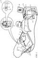
- Fig. 1is a pictorial illustration of a system 10 for evaluating electrical activity and performing ablative procedures on a heart 12 of a living subject, which is constructed and operative in accordance with a disclosed embodiment of the invention.
- the systemcomprises a catheter 14, which is percutaneously inserted by an operator 16 through the patient's vascular system into a chamber or vascular structure of the heart 12.
- the operator 16who is typically a physician, brings the catheter's distal tip 18 into contact with the heart wall, for example, at an ablation target site.
- Electrical activation mapsmay be prepared, according to the methods disclosed in U.S. Patent Nos. 6,226,542 , and 6,301,496 , and in commonly assigned U.S.
- Patent No. 6,892,091whose disclosures are herein incorporated by reference.
- One commercial product embodying elements of the system 10is available as the CARTO® 3 System, available from Biosense Webster, Inc., 3333 Diamond Canyon Road, Diamond Bar, CA 91765. This system may be modified by those skilled in the art to embody the principles of the invention described herein.
- Areas determined to be abnormalcan be ablated by application of thermal energy, e.g., by passage of radiofrequency electrical current through wires in the catheter to one or more electrodes at the distal tip 18, which apply the radiofrequency energy to the myocardium.
- the energyis absorbed in the tissue, heating it to a point (typically about 50°C) at which it permanently loses its electrical excitability.
- this procedurecreates non-conducting lesions in the cardiac tissue, which disrupt the abnormal electrical pathway causing the arrhythmia.
- the principles of the inventioncan be applied to different heart chambers to diagnose and treat many different cardiac arrhythmias.
- the catheter 14typically comprises a handle 20, having suitable controls on the handle to enable the operator 16 to steer, position and orient the distal end of the catheter as desired for the ablation.
- the distal portion of the catheter 14contains position sensors (not shown) that provide signals to a processor 22, located in a console 24.
- the processor 22may fulfill several processing functions as described below.
- Ablation energy and electrical signalscan be conveyed to and from the heart 12 through one or more ablation electrodes 32 located at or near the distal tip 18 via cable 34 to the console 24. Pacing signals and other control signals may be conveyed from the console 24 through the cable 34 and the electrodes 32 to the heart 12. Sensing electrodes 33, also connected to the console 24 are disposed between the ablation electrodes 32 and have connections to the cable 34.
- Wire connections 35link the console 24 with body surface electrodes 30 and other components of a positioning sub-system for measuring location and orientation coordinates of the catheter 14.
- the processor 22 or another processormay be an element of the positioning subsystem.
- the electrodes 32 and the body surface electrodes 30may be used to measure tissue impedance at the ablation site as taught in U.S. Patent No. 7,536,218, issued to Govari et al. , which is herein incorporated by reference.
- a sensor for bioelectric informatione.g., a temperature sensor (not shown), typically a thermocouple or thermistor, may be mounted on or near each of the electrodes 32.
- the console 24typically contains one or more ablation power generators 25.
- the catheter 14may be adapted to conduct ablative energy to the heart using any known ablation technique, e.g., radiofrequency energy, ultrasound energy, and laser-produced light energy. Such methods are disclosed in commonly assigned U.S. Patent Nos. 6,814,733 , 6,997,924 , and 7,156,816 , which are herein incorporated by reference.
- the positioning subsystemcomprises a magnetic position tracking arrangement that determines the position and orientation of the catheter 14 by generating magnetic fields in a predefined working volume and sensing these fields at the catheter, using field generating coils 28.
- the positioning subsystemis described in U.S. Patent No. 7,756,576 , which is hereby incorporated by reference, and in the above-noted U.S. Patent No. 7,536,218 .
- the catheter 14is coupled to the console 24, which enables the operator 16 to observe and regulate the functions of the catheter 14.
- Console 24includes a processor, preferably a computer with appropriate signal processing circuits.
- the processoris coupled to drive a monitor 29.
- the signal processing circuitstypically receive, amplify, filter and digitize signals from the catheter 14, including signals generated by sensors such as electrical, temperature and contact force sensors, and a plurality of location sensing electrodes (not shown) located distally in the catheter 14.
- the digitized signalsare received and used by the console 24 and the positioning system to compute the position and orientation of the catheter 14, and to analyze the electrical signals from the electrodes.
- the processor 22typically comprises an electroanatomic map generator, an image registration program, an image or data analysis program and a graphical user interface configured to present graphical information on the monitor 29.
- the system 10includes other elements, which are not shown in the figures for the sake of simplicity.
- the system 10may include an electrocardiogram (ECG) monitor, coupled to receive signals from one or more body surface electrodes, in order to provide an ECG synchronization signal to the console 24.
- ECGelectrocardiogram
- the system 10typically also includes a reference position sensor, either on an externally applied reference patch attached to the exterior of the subject's body, or on an internally placed catheter, which is inserted into the heart 12 maintained in a fixed position relative to the heart 12. Conventional pumps and lines for circulating liquids through the catheter 14 for cooling the ablation site are provided.
- the system 10may receive image data from an external imaging modality, such as an MRI unit or the like and includes image processors that can be incorporated in or invoked by the processor 22 for generating and displaying images.
- Fig. 2is a side elevation of distal end portion 37 of a catheter 39 adapted for cardiac ablation in accordance with an embodiment of the invention.
- the distal end portion 37is a generally hollow cylinder, having a typical diameter of 2.5 mm.
- Tip 41may be electrically conductive and function as an ablation electrode that is linked to a RF current generator.
- heatis generated through resistive heating of the tissue. The heat conducts to surrounding regions including the ablation electrode.
- irrigation apertures 43 or poresare formed in the distal end portion 37.
- the apertures 43typically have diameters in an approximate range of 0.05 - 0.2 mm.
- Irrigation fluidis supplied through an internal conduit (not shown) that extends through the lumen of the catheter 39.
- the rate of flow of the irrigation fluidis controlled by an irrigation module, and typically varies from 2 - 30 cc per minute but may be higher or lower than this range. A flow rate of 15 cc per minute is suitable for high flow requirements.
- the temperature about the distal end portion 37may be controlled in accordance with the teachings of commonly assigned copending Application Ser. No. 14/860,021 , U.S. Patent Application Publication No. 2015/0272667 and U.S. Patent Application Publication No. 2012/0157890 , which are all herein incorporated by reference.
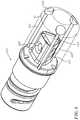
- Fig. 3is a longitudinal partially cut-away view of the distal end portion 37 of a catheter 45, in accordance with an embodiment of the invention.
- the distal end portion 37comprises a hollow electrode 47 having a lumen 49 (best seen in Fig. 4 ).
- the lumen 49is partially occupied by a fluid delivery assembly 51.
- the distal end portion 37has a longitudinal axis of symmetry 53.
- Apertures 57, 59 and other apertures 43are formed in side wall 55 of the electrode 47.
- the aperturesplace the exterior of the electrode 47 in fluid communication with the lumen 49 via channels, e.g., channels 61. Channels 61 are directed outward and backward.
- the term “backward”refers to a direction from distal tip 63 generally toward to a proximal end 65 of the distal end portion 37.
- the term “outward”refers to a direction generally away from the axis of symmetry 53. Longitudinal axes 67, 69 of the apertures 57, 59 intersect the axis of symmetry 53 at angles of incidence ⁇ 1 and ⁇ 2 , respectively.
- the angles of incidence of the outward, backward-directed apertures with the axis of symmetry 53may vary from 5 to 75 degrees, and are optimally around 45 degrees.
- Irrigation fluidis delivered under pressure from an external source through the catheter into assembly 51, The irrigation fluid exits the assembly 51 into the lumen 49 of the electrode 47. The irrigation fluid then exits the lumen 49 via the apertures 57, 59 in directions indicated by arrows in the axes 67, 69. Irrigation fluid so directed cools an area diagonally behind and outward of the distal end portion 37 as further explained below in the discussion of Fig. 7 .
- outward, forward-directed apertures 71, 73direct the irrigation fluid in directions specified by the angulations of their respective channels 75 with respect to the axis of symmetry 53, e.g., angle of incidence ⁇ 3 in the case of aperture 73 to deliver fluid diagonally forward and outward of the distal end portion 37.
- the distal end portion 37comprises conventional sideward directed apertures, e.g., apertures 77, 79, which direct the irrigation fluid outward and sideward from the distal end portion 37.
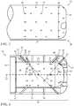
- FIG. 4is a cut-away sectional view of distal end portion 37 of the catheter 45 in accordance with an embodiment of the invention.
- Assembly 51mates with segment 81 of the catheter 45 and with the electrode 47.
- the assembly 51comprises an axial lumen 83 that conducts irrigation fluid distally toward a blocking terminus 85 that prevents the irrigation fluid from continuing in a forward direction.
- the irrigation fluid flowis indicated by an arrow 87.
- a plurality of channels 89branch trans-axially outward at 90° angles to the axial lumen 83, diverting the flow outward as indicated by arrows 91.
- the irrigation fluidenters the lumen 49 transverse to the axis of the catheter 45, generally toward the lateral channels in the electrode 47, such as the channels 61.
- irrigation flow through the channels 61would be disfavored, because the flow would be required to reverse course, and to turn more than 90 degrees to enter the proximally angled channels, such as the channels 61. It is an advantage of the arrangement of Fig. 4 that the irrigation flow is relatively more evenly distributed to all the holes in the electrode 47 than if the flow exited the assembly 51 in a forward direction.
- FIG. 5is an oblique elevation view of the assembly 51 ( Fig. 4 ) showing the channels 89 in accordance with an embodiment of the invention.
- this embodimentthere are three channels 89, which lie in a plane 93, and are distributed about the axis of the catheter at 120° angles.
- Direction of flow from the lumen 83 ( Fig. 4 ) to exit the assembly 51is indicated by broken lines 95.
- Other embodimentsmay have a different number of channels 89, typically varying from two to twelve channels.
- FIG. 6is a diagram illustrating irrigation flow patterns from a catheter in accordance with the prior art.
- a distal end portion 97comprises conventional sideward directed apertures. Plumes 99 of irrigation fluid are primarily directed outward at 90° to the longitudinal axis of the distal end portion 97. A smaller plume 101 is directed forward of the distal end portion 97.
- Fig. 7is a diagram illustrating irrigation flow patterns from a catheter in accordance with an embodiment of the invention.
- Plumes 103are directed diagonally backward from distal end portion 37, a feature, which is lacking in the case of Fig. 6 .
- plumes 105directed sideward
- plumes 107directed diagonally forward (lacking in Fig. 6 )
- plume 109directed forward of the distal end portion 37.
- Fig. 8is an oblique elevation of the distal end of a catheter 111, in accordance with an alternate embodiment of the invention.
- Assembly 113is disposed within electrode 47.
- the assembly 113has a second function - supporting sensors 115 through slots 117.
- the sensors 115can be any sensor suitable for obtaining electrophysiologic data from the body, e.g., temperature sensors for monitoring tissue ablation.
- the slots 117allow passage of the sensors through assembly 113 into the wall cavity of electrode 47. In operation, while the catheter is in the heart, different sensors may be inserted through the catheter through the slots 117 and retracted as dictated by the needs of the medical procedure.
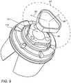
- Fig. 9is an oblique view of an assembly 119, in accordance with an alternate embodiment of the invention.
- Fig. 9is similar to Fig. 5 , except now there is a single transaxial channel 121 that forms a slot, extending about a sector about the circumference of the lumen 83 that can be 360 degrees as shown in Fig. 9 .
- more than one slotmay be distributed about the circumference of the assembly.
- a single gapprovides flow transverse to the axis of symmetry in a full 360 degree spread.
- Fig. 10is a cut-away sectional view of distal end portion 123 of a catheter 125 in accordance with an alternate embodiment of the invention.
- Assembly 127mates with segment 81 of the catheter 125 and with the electrode 47.
- the assembly 127lacks the channels 89 and the blocking terminus 85. Instead the flow exits the distal end of the assembly 127 and continues distally within the lumen 49, striking a baffle 129, which is spaced apart from the assembly 127 by a gap 133.
- the baffle 129deflects the flow of irrigation fluid transverse to the axis of symmetry toward the wall of the electrode 47 in a 360 degree radial spread, indicated by arrows 131. Thereafter, the irrigation fluid enters the channels 61 and the other channels that penetrate the wall of electrode 47 as described in the discussion of Fig. 4 .
Landscapes
- Health & Medical Sciences (AREA)
- Life Sciences & Earth Sciences (AREA)
- Surgery (AREA)
- Engineering & Computer Science (AREA)
- Plasma & Fusion (AREA)
- Medical Informatics (AREA)
- Otolaryngology (AREA)
- Physics & Mathematics (AREA)
- Cardiology (AREA)
- Biomedical Technology (AREA)
- Heart & Thoracic Surgery (AREA)
- Nuclear Medicine, Radiotherapy & Molecular Imaging (AREA)
- Molecular Biology (AREA)
- Animal Behavior & Ethology (AREA)
- General Health & Medical Sciences (AREA)
- Public Health (AREA)
- Veterinary Medicine (AREA)
- Surgical Instruments (AREA)
- Media Introduction/Drainage Providing Device (AREA)
Abstract
Description
- A portion of the disclosure of this patent document contains material that is subject to copyright protection. The copyright owner has no objection to the facsimile reproduction by anyone of the patent document or the patent disclosure, as it appears in the Patent and Trademark Office patent file or records, but otherwise reserves all copyright rights whatsoever.
- This invention relates to devices that introduce media into the body. More particularly, this invention relates to an ablation catheter having side holes for passage of fluid therethrough.
- In some medical procedures, energy is imparted to body tissue locally, in a concentrated dose, and it is desirable to cool the treatment area in order to reduce collateral tissue damage.
- A known difficulty in the use of radiofrequency energy for cardiac tissue ablation is controlling local heating of tissue. There are tradeoffs between the desire to create a sufficiently large lesion to effectively ablate an abnormal tissue focus, or block an aberrant conduction pattern, and the undesirable effects of excessive local heating. If the radiofrequency device creates too small a lesion, then the medical procedure could be less effective, or could require too much time. On the other hand, if tissues are heated excessively then there could be local charring effects, coagulum, and or steam pops due to overheating. Such overheated areas can develop high impedance, and may form a functional barrier to the passage of heat. The use of slower heating provides better control of the ablation, but unduly prolongs the procedure.
- It has been found that cooling the area of the ablation site reduces tissue charring and thrombus formation. For this purpose, Biosense Webster Inc. (Diamond Bar, California) offers the ThermoCool® irrigated-tip catheter as part of its integrated ablation system. The metal catheter tip, which is energized with RF current to ablate the tissue, has a number of peripheral holes, distributed circumferentially around the tip, for irrigation of the treatment site. A pump coupled to the catheter delivers saline solution to the catheter tip, and the solution flows out through the holes during the procedure in order to cool the catheter tip and the tissue.
- For example,
U.S. Patent No. 8,517,999 to Pappone et al. , describes an irrigated catheter With uniform cooling and/or uniform fluid distribution in longitudinally spaced apart elution holes by varying the diameter of a fluid delivery lumen. A number of elution holes are provided in a tip region of a catheter body, and these elution holes are in fluid communication with the lumen through ducts. - During an ablation procedure there is a concern that blood clots may form. Irrigation reduces the probability of clotting. However, with present catheter distal ends, there are one or more "blind regions" surrounding the end, particularly in the region "behind" the end. In these regions there is little or no irrigation.
- There is provided according to embodiments of the invention a medical apparatus, including a probe for insertion into a body of a subject, at least one electrode disposed on the distal section of the probe and coupled to an energy source to apply energy to tissue inside the body. A plurality of apertures are formed in the electrode. A fluid-directing assembly is disposed in the distal section of the probe having an axial channel that is in fluid communication with at least one trans-axial channel disposed at right angles to the axial channel and leading to an exterior of the assembly. A blocking terminus is disposed forward of the at least one trans-axial channel that prevents irrigation fluid from flowing axially in a forward direction.
- According to an aspect of the apparatus, some of the apertures are oriented at a backward angle with respect to the axis of symmetry to deliver the fluid that exits the assembly diagonally behind and outward of the distal section.
- According to another aspect of the apparatus, the assembly comprises between two and twelve trans-axial channels.
- According to still another aspect of the apparatus, the assembly includes exactly one trans-axial channel.
- According to one aspect of the apparatus, the apertures have diameters in a range of 0.05 - 0.2 mm.
- According to a further aspect of the apparatus, the distal section of the probe has a diameter of 2.5 mm.
- According to yet another aspect of the apparatus, some of the apertures are oriented at a forward angle with respect to the axis of symmetry to deliver the fluid diagonally forward and outward of the distal section.
- According to one aspect of the apparatus, the assembly also includes at least one notch adapted to support a sensor within the lumen of the electrode.
- There is further provided according to embodiments of the invention a method for cardiac ablation, which is carried out by introducing a probe into a heart of a subject. The probe has at least one hollow electrode disposed on its distal section, the electrode being coupled to an energy source to apply energy to tissue in the heart. The electrode a plurality of apertures formed through its wall. The method is further carried out by locating the distal section of the probe in proximity to a target in the heart, and thereafter conducting ablation energy via the electrode into the heart to affect an abnormal electrical conduction therein. While conducting ablation energy conveying irrigation fluid into an axial channel of a fluid-directing assembly in the distal section, and directing the irrigation fluid from the axial channel through a plurality of trans-axial channels disposed at right angles to the axial channel and leading to an exterior of the assembly while blocking the irrigation fluid from flowing axially in a forward direction beyond the trans-axial channels.
- An aspect of the method is carried out by passing a sensor via the probe onto a support in the assembly, and sensing bioelectric information from the heart with the sensor.
- For a better understanding of the present invention, reference is made to the detailed description of the invention, by way of example, which is to be read in conjunction with the following drawings, wherein like elements are given like reference numerals, and wherein:
Fig. 1 is a pictorial illustration of a system for performing cardiac ablative procedures in accordance with an embodiment of the invention;Fig. 2 a side elevation of the distal end portion of a catheter in accordance with an embodiment of the invention;Fig. 3 a longitudinal sectional view of the distal end portion shown inFig. 2 in accordance with an embodiment of the invention;Fig. 4 is a cut-away sectional view of a distal segment of an ablation catheter showing a fluid-directing assembly in accordance with an embodiment of the invention;Fig. 5 is an oblique elevation of the fluid-directing assembly shown inFig. 4 in accordance with an embodiment of the invention;Fig. 6 is a diagram illustrating irrigation flow patterns from a catheter in accordance with the prior art;Fig. 7 is a diagram illustrating irrigation flow patterns from a catheter in accordance with an embodiment of the invention;Fig. 8 is an oblique elevation of the distal end of a catheter in accordance with an alternate embodiment of the invention;Fig. 9 is an oblique elevation of the fluid-directing assembly shown inFig. 4 in accordance with an alternate embodiment of the invention; andFig. 10 is a cut-away sectional view of a distal segment of an ablation catheter showing a fluid-directing assembly in accordance with an alternate embodiment of the invention.- In the following description, numerous specific details are set forth in order to provide a thorough understanding of the various principles of the present invention. It will be apparent to one skilled in the art, however, that not all these details are necessarily needed for practicing the present invention. In this instance, well-known circuits, control logic, and the details of computer program instructions for conventional algorithms and processes have not been shown in detail in order not to obscure the general concepts unnecessarily.
- Documents incorporated by reference herein are to be considered an integral part of the application except that, to the extent that any terms are defined in these incorporated documents in a manner that conflicts with definitions made explicitly or implicitly in the present specification, only the definitions in the present specification should be considered.
- Turning now to the drawings, reference is initially made to
Fig. 1 , which is a pictorial illustration of a system 10 for evaluating electrical activity and performing ablative procedures on aheart 12 of a living subject, which is constructed and operative in accordance with a disclosed embodiment of the invention. The system comprises acatheter 14, which is percutaneously inserted by anoperator 16 through the patient's vascular system into a chamber or vascular structure of theheart 12. Theoperator 16, who is typically a physician, brings the catheter'sdistal tip 18 into contact with the heart wall, for example, at an ablation target site. Electrical activation maps may be prepared, according to the methods disclosed inU.S. Patent Nos. 6,226,542 , and6,301,496 , and in commonly assignedU.S. Patent No. 6,892,091 , whose disclosures are herein incorporated by reference. One commercial product embodying elements of the system 10 is available as the CARTO® 3 System, available from Biosense Webster, Inc., 3333 Diamond Canyon Road, Diamond Bar, CA 91765. This system may be modified by those skilled in the art to embody the principles of the invention described herein. - Areas determined to be abnormal, for example by evaluation of the electrical activation maps, can be ablated by application of thermal energy, e.g., by passage of radiofrequency electrical current through wires in the catheter to one or more electrodes at the
distal tip 18, which apply the radiofrequency energy to the myocardium. The energy is absorbed in the tissue, heating it to a point (typically about 50°C) at which it permanently loses its electrical excitability. When successful, this procedure creates non-conducting lesions in the cardiac tissue, which disrupt the abnormal electrical pathway causing the arrhythmia. The principles of the invention can be applied to different heart chambers to diagnose and treat many different cardiac arrhythmias. - The
catheter 14 typically comprises ahandle 20, having suitable controls on the handle to enable theoperator 16 to steer, position and orient the distal end of the catheter as desired for the ablation. To aid theoperator 16, the distal portion of thecatheter 14 contains position sensors (not shown) that provide signals to aprocessor 22, located in aconsole 24. Theprocessor 22 may fulfill several processing functions as described below. - Ablation energy and electrical signals can be conveyed to and from the
heart 12 through one ormore ablation electrodes 32 located at or near thedistal tip 18 viacable 34 to theconsole 24. Pacing signals and other control signals may be conveyed from theconsole 24 through thecable 34 and theelectrodes 32 to theheart 12.Sensing electrodes 33, also connected to theconsole 24 are disposed between theablation electrodes 32 and have connections to thecable 34. Wire connections 35 link theconsole 24 withbody surface electrodes 30 and other components of a positioning sub-system for measuring location and orientation coordinates of thecatheter 14. Theprocessor 22 or another processor (not shown) may be an element of the positioning subsystem. Theelectrodes 32 and thebody surface electrodes 30 may be used to measure tissue impedance at the ablation site as taught inU.S. Patent No. 7,536,218, issued to Govari et al. , which is herein incorporated by reference. A sensor for bioelectric information, e.g., a temperature sensor (not shown), typically a thermocouple or thermistor, may be mounted on or near each of theelectrodes 32.- The
console 24 typically contains one or moreablation power generators 25. Thecatheter 14 may be adapted to conduct ablative energy to the heart using any known ablation technique, e.g., radiofrequency energy, ultrasound energy, and laser-produced light energy. Such methods are disclosed in commonly assignedU.S. Patent Nos. 6,814,733 ,6,997,924 , and7,156,816 , which are herein incorporated by reference. - In one embodiment, the positioning subsystem comprises a magnetic position tracking arrangement that determines the position and orientation of the
catheter 14 by generating magnetic fields in a predefined working volume and sensing these fields at the catheter, using field generating coils 28. The positioning subsystem is described inU.S. Patent No. 7,756,576 , which is hereby incorporated by reference, and in the above-notedU.S. Patent No. 7,536,218 . - As noted above, the
catheter 14 is coupled to theconsole 24, which enables theoperator 16 to observe and regulate the functions of thecatheter 14.Console 24 includes a processor, preferably a computer with appropriate signal processing circuits. The processor is coupled to drive amonitor 29. The signal processing circuits typically receive, amplify, filter and digitize signals from thecatheter 14, including signals generated by sensors such as electrical, temperature and contact force sensors, and a plurality of location sensing electrodes (not shown) located distally in thecatheter 14. The digitized signals are received and used by theconsole 24 and the positioning system to compute the position and orientation of thecatheter 14, and to analyze the electrical signals from the electrodes. - In order to generate electroanatomic maps, the
processor 22 typically comprises an electroanatomic map generator, an image registration program, an image or data analysis program and a graphical user interface configured to present graphical information on themonitor 29. - Typically, the system 10 includes other elements, which are not shown in the figures for the sake of simplicity. For example, the system 10 may include an electrocardiogram (ECG) monitor, coupled to receive signals from one or more body surface electrodes, in order to provide an ECG synchronization signal to the
console 24. As mentioned above, the system 10 typically also includes a reference position sensor, either on an externally applied reference patch attached to the exterior of the subject's body, or on an internally placed catheter, which is inserted into theheart 12 maintained in a fixed position relative to theheart 12. Conventional pumps and lines for circulating liquids through thecatheter 14 for cooling the ablation site are provided. The system 10 may receive image data from an external imaging modality, such as an MRI unit or the like and includes image processors that can be incorporated in or invoked by theprocessor 22 for generating and displaying images. - Reference is now made to
Fig. 2 , which is a side elevation ofdistal end portion 37 of acatheter 39 adapted for cardiac ablation in accordance with an embodiment of the invention. Thedistal end portion 37 is a generally hollow cylinder, having a typical diameter of 2.5 mm.Tip 41 may be electrically conductive and function as an ablation electrode that is linked to a RF current generator. Typically, during ablation, heat is generated through resistive heating of the tissue. The heat conducts to surrounding regions including the ablation electrode. In order to dissipate the heat and dilute the surrounding blood,irrigation apertures 43 or pores are formed in thedistal end portion 37. Theapertures 43 typically have diameters in an approximate range of 0.05 - 0.2 mm. 0.075 mm apertures are used in a current embodiment. Irrigation fluid is supplied through an internal conduit (not shown) that extends through the lumen of thecatheter 39. The rate of flow of the irrigation fluid is controlled by an irrigation module, and typically varies from 2 - 30 cc per minute but may be higher or lower than this range. A flow rate of 15 cc per minute is suitable for high flow requirements. By varying either or both of the rate of flow and the temperature of the irrigation fluid, the temperature about thedistal end portion 37 may be controlled in accordance with the teachings of commonly assigned copending Application Ser. No.14/860,021 U.S. Patent Application Publication No. 2015/0272667 andU.S. Patent Application Publication No. 2012/0157890 , which are all herein incorporated by reference. - Reference is now made to
Fig. 3 , which is a longitudinal partially cut-away view of thedistal end portion 37 of acatheter 45, in accordance with an embodiment of the invention. Thedistal end portion 37 comprises ahollow electrode 47 having a lumen 49 (best seen inFig. 4 ). Thelumen 49 is partially occupied by afluid delivery assembly 51. Thedistal end portion 37 has a longitudinal axis of symmetry 53.Apertures Fig. 2 ) are formed inside wall 55 of theelectrode 47. The apertures place the exterior of theelectrode 47 in fluid communication with thelumen 49 via channels, e.g.,channels 61.Channels 61 are directed outward and backward. For purposes of this disclosure, the term "backward" refers to a direction fromdistal tip 63 generally toward to aproximal end 65 of thedistal end portion 37. The term "outward" refers to a direction generally away from the axis of symmetry 53.Longitudinal axes apertures - Irrigation fluid is delivered under pressure from an external source through the catheter into
assembly 51, The irrigation fluid exits theassembly 51 into thelumen 49 of theelectrode 47. The irrigation fluid then exits thelumen 49 via theapertures axes distal end portion 37 as further explained below in the discussion ofFig. 7 . - Similarly, outward, forward-directed
apertures respective channels 75 with respect to the axis of symmetry 53, e.g., angle of incidence θ3 in the case ofaperture 73 to deliver fluid diagonally forward and outward of thedistal end portion 37. - Additionally, the
distal end portion 37 comprises conventional sideward directed apertures, e.g.,apertures distal end portion 37. - Reference is now made to
Fig. 4 , which is a cut-away sectional view ofdistal end portion 37 of thecatheter 45 in accordance with an embodiment of the invention.Assembly 51 mates withsegment 81 of thecatheter 45 and with theelectrode 47. Theassembly 51 comprises anaxial lumen 83 that conducts irrigation fluid distally toward a blockingterminus 85 that prevents the irrigation fluid from continuing in a forward direction. The irrigation fluid flow is indicated by anarrow 87. At the terminus 85 a plurality ofchannels 89 branch trans-axially outward at 90° angles to theaxial lumen 83, diverting the flow outward as indicated byarrows 91. The irrigation fluid enters thelumen 49 transverse to the axis of thecatheter 45, generally toward the lateral channels in theelectrode 47, such as thechannels 61. - If the irrigation path exited the
lumen 83 in alignment with the axis of symmetry 53 (Fig. 3 ), irrigation flow through thechannels 61 would be disfavored, because the flow would be required to reverse course, and to turn more than 90 degrees to enter the proximally angled channels, such as thechannels 61. It is an advantage of the arrangement ofFig. 4 that the irrigation flow is relatively more evenly distributed to all the holes in theelectrode 47 than if the flow exited theassembly 51 in a forward direction. - Reference is now made to
Fig. 5 , which is an oblique elevation view of the assembly 51 (Fig. 4 ) showing thechannels 89 in accordance with an embodiment of the invention. In this embodiment there are threechannels 89, which lie in aplane 93, and are distributed about the axis of the catheter at 120° angles. Direction of flow from the lumen 83 (Fig. 4 ) to exit theassembly 51 is indicated bybroken lines 95. Other embodiments may have a different number ofchannels 89, typically varying from two to twelve channels. - Reference is now made to
Fig. 6 , which is a diagram illustrating irrigation flow patterns from a catheter in accordance with the prior art. Adistal end portion 97 comprises conventional sideward directed apertures.Plumes 99 of irrigation fluid are primarily directed outward at 90° to the longitudinal axis of thedistal end portion 97. Asmaller plume 101 is directed forward of thedistal end portion 97. - Reference is now made to
Fig. 7 , which is a diagram illustrating irrigation flow patterns from a catheter in accordance with an embodiment of the invention.Plumes 103 are directed diagonally backward fromdistal end portion 37, a feature, which is lacking in the case ofFig. 6 . In addition there areplumes 105 directed sideward,plumes 107 directed diagonally forward (lacking inFig. 6 ), andplume 109 directed forward of thedistal end portion 37. - Reference is now made to
Fig. 8 , which is an oblique elevation of the distal end of acatheter 111, in accordance with an alternate embodiment of the invention.Assembly 113 is disposed withinelectrode 47. In addition to the fluid diversion function described above, theassembly 113 has a second function - supportingsensors 115 throughslots 117. Thesensors 115 can be any sensor suitable for obtaining electrophysiologic data from the body, e.g., temperature sensors for monitoring tissue ablation. Theslots 117 allow passage of the sensors throughassembly 113 into the wall cavity ofelectrode 47. In operation, while the catheter is in the heart, different sensors may be inserted through the catheter through theslots 117 and retracted as dictated by the needs of the medical procedure. - Reference is now made to
Fig. 9 , which is an oblique view of anassembly 119, in accordance with an alternate embodiment of the invention.Fig. 9 is similar toFig. 5 , except now there is a singletransaxial channel 121 that forms a slot, extending about a sector about the circumference of thelumen 83 that can be 360 degrees as shown inFig. 9 . There may be one slot as shown inFig. 9 . Alternatively more than one slot may be distributed about the circumference of the assembly. - In this embodiment a single gap provides flow transverse to the axis of symmetry in a full 360 degree spread. Reference is now made to
Fig. 10 , which is a cut-away sectional view ofdistal end portion 123 of acatheter 125 in accordance with an alternate embodiment of the invention.Assembly 127 mates withsegment 81 of thecatheter 125 and with theelectrode 47. Unlike the embodiment ofFig. 4 , theassembly 127 lacks thechannels 89 and the blockingterminus 85. Instead the flow exits the distal end of theassembly 127 and continues distally within thelumen 49, striking abaffle 129, which is spaced apart from theassembly 127 by agap 133. Thebaffle 129 deflects the flow of irrigation fluid transverse to the axis of symmetry toward the wall of theelectrode 47 in a 360 degree radial spread, indicated byarrows 131. Thereafter, the irrigation fluid enters thechannels 61 and the other channels that penetrate the wall ofelectrode 47 as described in the discussion ofFig. 4 . - It will be appreciated by persons skilled in the art that the present invention is not limited to what has been particularly shown and described hereinabove. Rather, the scope of the present invention includes both combinations and sub-combinations of the various features described hereinabove, as well as variations and modifications thereof that are not in the prior art, which would occur to persons skilled in the art upon reading the foregoing description.
- 1. A method for cardiac ablation, comprising the steps of:
- introducing a probe into a heart of a subject, the probe having a distal section, a longitudinal axis of symmetry, at least one electrode disposed on the distal section of the probe and coupled to an energy source to apply energy to tissue in the heart, the electrode having an outer surface, and a wall having a plurality of apertures formed therethrough;
- locating the distal section of the probe in proximity to a target in the heart;
- thereafter conducting ablation energy via the electrode into the heart to affect an abnormal electrical conduction therein;
- while conducting ablation energy conveying irrigation fluid into an axial channel of a fluid-directing assembly in the distal section; and
- directing the irrigation fluid from the axial channel through a plurality of trans-axial channels disposed at right angles to the axial channel and leading to an exterior of the assembly while blocking the irrigation fluid from flowing axially in a forward direction beyond the trans-axial channels.
- 2. The method according to
aspect 1, wherein a portion of the apertures are oriented at a backward angle with respect to the axis of symmetry; further comprising:- while conducting ablation energy cooling a volume diagonally behind and outward of the distal section by flowing the irrigation fluid through the portion of the apertures.
- 3. The method according to
aspect 1, wherein the apertures have diameters in a range of 0.05 - 0.2 mm. - 4. The method according to
aspect 1, wherein the distal section has a diameter of 2.5 mm. - 5. The method according to
aspect 1, wherein directing the irrigation fluid is performed in a range of 2 - 30 cc per minute. - 6. The method according to
aspect 1, wherein directing the irrigation fluid is performed in a range of 2 - 15 cc per minute. - 7. The method according to
aspect 1, further comprising:- passing a sensor via the probe onto a support in the assembly; and
- sensing bioelectric information from the heart with the sensor.
Claims (9)
- A medical apparatus, comprising:a probe, having a distal section for insertion into a body of a subject and a longitudinal axis of symmetry;at least one electrode disposed on the distal section of the probe and coupled to an energy source to apply energy to tissue inside the body, the electrode having an outer surface, a lumen, and a wall having a plurality of apertures formed therethrough, anda fluid-directing assembly in the distal section having an axial channel that is in fluid communication with at least one trans-axial channel disposed at right angles to the axial channel and leading to an exterior of the assembly, and a blocking terminus disposed forward of the at least one trans-axial channel that prevents an irrigation fluid from flowing axially in a forward direction.
- The apparatus according to claim 1, wherein some of the apertures are oriented at a backward angle with respect to the axis of symmetry to deliver the fluid that exits the assembly diagonally behind and outward of the distal section.
- The apparatus according to claim 1, wherein the assembly comprises between two and twelve trans-axial channels.
- The apparatus according to claim 1, wherein the assembly comprises exactly one trans-axial channel.
- The apparatus according to claim 4, wherein the exactly one trans-axial channel extends 360 degrees about the axis of symmetry.
- The apparatus according to claim 1, wherein the apertures have diameters in a range of 0.05 - 0.2 mm.
- The apparatus according to claim 1, wherein the distal section has a diameter of 2.5 mm.
- The apparatus according to claim 1, wherein some of the apertures are oriented at a forward angle with respect to the axis of symmetry to deliver the fluid diagonally forward and outward of the distal section.
- The apparatus according to claim 1, wherein the assembly further comprises at least one notch adapted to support a sensor within the lumen of the electrode.
Priority Applications (1)
| Application Number | Priority Date | Filing Date | Title |
|---|---|---|---|
| EP22180671.4AEP4082462A1 (en) | 2016-10-17 | 2017-10-16 | Catheter with angled irrigation holes |
Applications Claiming Priority (1)
| Application Number | Priority Date | Filing Date | Title |
|---|---|---|---|
| US15/295,296US11020174B2 (en) | 2016-10-17 | 2016-10-17 | Catheter with angled irrigation holes |
Related Child Applications (1)
| Application Number | Title | Priority Date | Filing Date |
|---|---|---|---|
| EP22180671.4ADivisionEP4082462A1 (en) | 2016-10-17 | 2017-10-16 | Catheter with angled irrigation holes |
Publications (2)
| Publication Number | Publication Date |
|---|---|
| EP3308730A1true EP3308730A1 (en) | 2018-04-18 |
| EP3308730B1 EP3308730B1 (en) | 2022-07-13 |
Family
ID=60117559
Family Applications (2)
| Application Number | Title | Priority Date | Filing Date |
|---|---|---|---|
| EP22180671.4APendingEP4082462A1 (en) | 2016-10-17 | 2017-10-16 | Catheter with angled irrigation holes |
| EP17196531.2AActiveEP3308730B1 (en) | 2016-10-17 | 2017-10-16 | Catheter with angled irrigation holes |
Family Applications Before (1)
| Application Number | Title | Priority Date | Filing Date |
|---|---|---|---|
| EP22180671.4APendingEP4082462A1 (en) | 2016-10-17 | 2017-10-16 | Catheter with angled irrigation holes |
Country Status (7)
| Country | Link |
|---|---|
| US (3) | US11020174B2 (en) |
| EP (2) | EP4082462A1 (en) |
| JP (1) | JP7134615B2 (en) |
| CN (1) | CN107951560B (en) |
| AU (1) | AU2017235895A1 (en) |
| CA (1) | CA2981578A1 (en) |
| IL (1) | IL254682B (en) |
Families Citing this family (6)
| Publication number | Priority date | Publication date | Assignee | Title |
|---|---|---|---|---|
| US11439742B2 (en)* | 2017-02-08 | 2022-09-13 | Veran Medical Technologies, Inc. | Localization needle |
| CN113347932B (en)* | 2018-11-07 | 2025-05-27 | 伯恩森斯韦伯斯特(以色列)有限责任公司 | Cryoballoon with directional gas control |
| US11172984B2 (en) | 2019-05-03 | 2021-11-16 | Biosense Webster (Israel) Ltd. | Device, system and method to ablate cardiac tissue |
| US20220395322A1 (en) | 2021-06-15 | 2022-12-15 | Biosense Webster (Israel) Ltd. | Catheter for high-power focal ablation |
| US20240189545A1 (en)* | 2022-12-13 | 2024-06-13 | Biosense Webster (Israel) Ltd. | Grooved catheter with recessed irrigation holes |
| CN116687553B (en)* | 2023-06-12 | 2023-10-10 | 成都德倍佳医疗科技有限责任公司 | Fluid controllable hemostatic front-end assembly, electrode and system thereof |
Citations (16)
| Publication number | Priority date | Publication date | Assignee | Title |
|---|---|---|---|---|
| US6226542B1 (en) | 1998-07-24 | 2001-05-01 | Biosense, Inc. | Three-dimensional reconstruction of intrabody organs |
| US6301496B1 (en) | 1998-07-24 | 2001-10-09 | Biosense, Inc. | Vector mapping of three-dimensionally reconstructed intrabody organs and method of display |
| US6814733B2 (en) | 2002-01-31 | 2004-11-09 | Biosense, Inc. | Radio frequency pulmonary vein isolation |
| US6892091B1 (en) | 2000-02-18 | 2005-05-10 | Biosense, Inc. | Catheter, method and apparatus for generating an electrical map of a chamber of the heart |
| US6997924B2 (en) | 2002-09-17 | 2006-02-14 | Biosense Inc. | Laser pulmonary vein isolation |
| US7156816B2 (en) | 2002-11-26 | 2007-01-02 | Biosense, Inc. | Ultrasound pulmonary vein isolation |
| US20090125016A1 (en)* | 2007-11-13 | 2009-05-14 | St. Jude Medical, Atrial Fibrillation Division, Inc. | Irrigated ablation electrode having proximal direction flow |
| US7536218B2 (en) | 2005-07-15 | 2009-05-19 | Biosense Webster, Inc. | Hybrid magnetic-based and impedance-based position sensing |
| US7756576B2 (en) | 2005-08-26 | 2010-07-13 | Biosense Webster, Inc. | Position sensing and detection of skin impedance |
| US20110257649A1 (en)* | 2010-04-20 | 2011-10-20 | Vascomed Gmbh | Electrode For An Electrophysiological Ablation Catheter |
| US20120157890A1 (en) | 2010-12-16 | 2012-06-21 | Assaf Govari | System for controlling tissue ablation using temperature sensors |
| US8517999B2 (en) | 2007-04-04 | 2013-08-27 | St. Jude Medical, Atrial Fibrillation Division, Inc. | Irrigated catheter with improved fluid flow |
| US20140276758A1 (en)* | 2013-03-15 | 2014-09-18 | Boston Scientific Scimed, Inc. | Open irrigated ablation catheter |
| EP2913017A1 (en)* | 2014-02-27 | 2015-09-02 | Osypka Ag. | Irrigated ablation catheter |
| US20150272669A1 (en)* | 2014-04-01 | 2015-10-01 | Gregory G. Brucker | Temperature-Responsive Irrigated Ablation Electrode with Reduced Coolant Flow and related methods for making and using |
| US20150272667A1 (en) | 2014-03-27 | 2015-10-01 | Biosense Webster (Israel) Ltd. | Temperature measurement in catheter |
Family Cites Families (16)
| Publication number | Priority date | Publication date | Assignee | Title |
|---|---|---|---|---|
| US5634897A (en) | 1993-10-08 | 1997-06-03 | Lake Region Manufacturing, Inc. | Rheolytic occlusion removal catheter system and method |
| US6969373B2 (en) | 2001-04-13 | 2005-11-29 | Tricardia, Llc | Syringe system |
| US6893091B1 (en) | 2002-05-07 | 2005-05-17 | Martin Fenner | Side-vented enclosure and telescoping rail system |
| US20060129091A1 (en) | 2004-12-10 | 2006-06-15 | Possis Medical, Inc. | Enhanced cross stream mechanical thrombectomy catheter with backloading manifold |
| US7536216B2 (en) | 2004-10-18 | 2009-05-19 | Siemens Medical Solutions Usa, Inc. | Method and system for virtual endoscopy with guidance for biopsy |
| US7857810B2 (en)* | 2006-05-16 | 2010-12-28 | St. Jude Medical, Atrial Fibrillation Division, Inc. | Ablation electrode assembly and methods for improved control of temperature and minimization of coagulation and tissue damage |
| US8690870B2 (en)* | 2006-12-28 | 2014-04-08 | St. Jude Medical, Atrial Fibrillation Division, Inc. | Irrigated ablation catheter system with pulsatile flow to prevent thrombus |
| US8460285B2 (en)* | 2006-12-29 | 2013-06-11 | St. Jude Medical, Atrial Fibrillation Division, Inc. | Ablation catheter electrode having multiple thermal sensors and method of use |
| US8979837B2 (en)* | 2007-04-04 | 2015-03-17 | St. Jude Medical, Atrial Fibrillation Division, Inc. | Flexible tip catheter with extended fluid lumen |
| EP2453821A1 (en) | 2009-07-13 | 2012-05-23 | Boston Scientific Scimed, Inc. | Open-irrigated ablation catheter with turbulent flow |
| EP2604209B1 (en)* | 2011-12-13 | 2017-08-02 | VascoMed GmbH | Irrigation catheter device and ablation system |
| US8956353B2 (en)* | 2011-12-29 | 2015-02-17 | Biosense Webster (Israel) Ltd. | Electrode irrigation using micro-jets |
| US9238122B2 (en) | 2012-01-26 | 2016-01-19 | Covidien Lp | Thrombectomy catheter systems |
| US20140276562A1 (en)* | 2013-03-14 | 2014-09-18 | Biosense Webster (Israel), Ltd. | Catheter with spray irrigation |
| EP2967731B1 (en)* | 2013-03-15 | 2020-10-07 | Boston Scientific Scimed, Inc. | Open irrigated ablation catheter with proximal cooling |
| US10327859B2 (en) | 2015-09-21 | 2019-06-25 | Biosense Webster (Israel) Ltd. | Catheter stability indication |
- 2016
- 2016-10-17USUS15/295,296patent/US11020174B2/enactiveActive
- 2017
- 2017-09-25ILIL254682Apatent/IL254682B/enunknown
- 2017-09-26AUAU2017235895Apatent/AU2017235895A1/ennot_activeAbandoned
- 2017-10-05CACA2981578Apatent/CA2981578A1/ennot_activeAbandoned
- 2017-10-16EPEP22180671.4Apatent/EP4082462A1/enactivePending
- 2017-10-16JPJP2017200129Apatent/JP7134615B2/enactiveActive
- 2017-10-16EPEP17196531.2Apatent/EP3308730B1/enactiveActive
- 2017-10-17CNCN201710977646.9Apatent/CN107951560B/enactiveActive
- 2021
- 2021-05-31USUS17/335,029patent/US12161395B2/enactiveActive
- 2024
- 2024-12-06USUS18/972,304patent/US20250099174A1/enactivePending
Patent Citations (16)
| Publication number | Priority date | Publication date | Assignee | Title |
|---|---|---|---|---|
| US6301496B1 (en) | 1998-07-24 | 2001-10-09 | Biosense, Inc. | Vector mapping of three-dimensionally reconstructed intrabody organs and method of display |
| US6226542B1 (en) | 1998-07-24 | 2001-05-01 | Biosense, Inc. | Three-dimensional reconstruction of intrabody organs |
| US6892091B1 (en) | 2000-02-18 | 2005-05-10 | Biosense, Inc. | Catheter, method and apparatus for generating an electrical map of a chamber of the heart |
| US6814733B2 (en) | 2002-01-31 | 2004-11-09 | Biosense, Inc. | Radio frequency pulmonary vein isolation |
| US6997924B2 (en) | 2002-09-17 | 2006-02-14 | Biosense Inc. | Laser pulmonary vein isolation |
| US7156816B2 (en) | 2002-11-26 | 2007-01-02 | Biosense, Inc. | Ultrasound pulmonary vein isolation |
| US7536218B2 (en) | 2005-07-15 | 2009-05-19 | Biosense Webster, Inc. | Hybrid magnetic-based and impedance-based position sensing |
| US7756576B2 (en) | 2005-08-26 | 2010-07-13 | Biosense Webster, Inc. | Position sensing and detection of skin impedance |
| US8517999B2 (en) | 2007-04-04 | 2013-08-27 | St. Jude Medical, Atrial Fibrillation Division, Inc. | Irrigated catheter with improved fluid flow |
| US20090125016A1 (en)* | 2007-11-13 | 2009-05-14 | St. Jude Medical, Atrial Fibrillation Division, Inc. | Irrigated ablation electrode having proximal direction flow |
| US20110257649A1 (en)* | 2010-04-20 | 2011-10-20 | Vascomed Gmbh | Electrode For An Electrophysiological Ablation Catheter |
| US20120157890A1 (en) | 2010-12-16 | 2012-06-21 | Assaf Govari | System for controlling tissue ablation using temperature sensors |
| US20140276758A1 (en)* | 2013-03-15 | 2014-09-18 | Boston Scientific Scimed, Inc. | Open irrigated ablation catheter |
| EP2913017A1 (en)* | 2014-02-27 | 2015-09-02 | Osypka Ag. | Irrigated ablation catheter |
| US20150272667A1 (en) | 2014-03-27 | 2015-10-01 | Biosense Webster (Israel) Ltd. | Temperature measurement in catheter |
| US20150272669A1 (en)* | 2014-04-01 | 2015-10-01 | Gregory G. Brucker | Temperature-Responsive Irrigated Ablation Electrode with Reduced Coolant Flow and related methods for making and using |
Also Published As
| Publication number | Publication date |
|---|---|
| IL254682A0 (en) | 2017-11-30 |
| US20180104000A1 (en) | 2018-04-19 |
| CN107951560B (en) | 2022-10-04 |
| AU2017235895A1 (en) | 2018-05-10 |
| JP7134615B2 (en) | 2022-09-12 |
| CN107951560A (en) | 2018-04-24 |
| US11020174B2 (en) | 2021-06-01 |
| US20250099174A1 (en) | 2025-03-27 |
| JP2018064939A (en) | 2018-04-26 |
| US12161395B2 (en) | 2024-12-10 |
| CA2981578A1 (en) | 2018-04-17 |
| US20210282848A1 (en) | 2021-09-16 |
| EP4082462A1 (en) | 2022-11-02 |
| EP3308730B1 (en) | 2022-07-13 |
| IL254682B (en) | 2022-03-01 |
Similar Documents
| Publication | Publication Date | Title |
|---|---|---|
| US12161395B2 (en) | Catheter with angled irrigation holes | |
| JP6571217B2 (en) | Medical equipment | |
| AU2019280061B2 (en) | Irrigated electrodes with enhanced heat conduction | |
| EP3037034B1 (en) | Balloon for ablation around pulmonary veins | |
| EP2870939B1 (en) | Catheter with means for detecting loss of contact of ablation electrode | |
| CN109199578A (en) | It is melted using the temperature controlled short duration of multiple electrodes | |
| JP2021186657A (en) | Application of irreversible electroporation (ire) ablation using catheter with electrode array | |
| JP7707494B2 (en) | Electrode short circuit | |
| US20240189545A1 (en) | Grooved catheter with recessed irrigation holes | |
| JP4871559B2 (en) | Cooling RF ablation needle | |
| CN118177955A (en) | Grooved catheter with recessed flush hole | |
| EP1767165A1 (en) | Cooled RF ablation needle |
Legal Events
| Date | Code | Title | Description |
|---|---|---|---|
| PUAI | Public reference made under article 153(3) epc to a published international application that has entered the european phase | Free format text:ORIGINAL CODE: 0009012 | |
| STAA | Information on the status of an ep patent application or granted ep patent | Free format text:STATUS: THE APPLICATION HAS BEEN PUBLISHED | |
| AK | Designated contracting states | Kind code of ref document:A1 Designated state(s):AL AT BE BG CH CY CZ DE DK EE ES FI FR GB GR HR HU IE IS IT LI LT LU LV MC MK MT NL NO PL PT RO RS SE SI SK SM TR | |
| AX | Request for extension of the european patent | Extension state:BA ME | |
| STAA | Information on the status of an ep patent application or granted ep patent | Free format text:STATUS: REQUEST FOR EXAMINATION WAS MADE | |
| 17P | Request for examination filed | Effective date:20181016 | |
| RAX | Requested extension states of the european patent have changed | Extension state:BA Payment date:20181016 Extension state:ME Payment date:20181016 | |
| RBV | Designated contracting states (corrected) | Designated state(s):AL AT BE BG CH CY CZ DE DK EE ES FI FR GB GR HR HU IE IS IT LI LT LU LV MC MK MT NL NO PL PT RO RS SE SI SK SM TR | |
| GRAP | Despatch of communication of intention to grant a patent | Free format text:ORIGINAL CODE: EPIDOSNIGR1 | |
| STAA | Information on the status of an ep patent application or granted ep patent | Free format text:STATUS: GRANT OF PATENT IS INTENDED | |
| INTG | Intention to grant announced | Effective date:20220203 | |
| GRAS | Grant fee paid | Free format text:ORIGINAL CODE: EPIDOSNIGR3 | |
| GRAA | (expected) grant | Free format text:ORIGINAL CODE: 0009210 | |
| STAA | Information on the status of an ep patent application or granted ep patent | Free format text:STATUS: THE PATENT HAS BEEN GRANTED | |
| RAP3 | Party data changed (applicant data changed or rights of an application transferred) | Owner name:BIOSENSE WEBSTER (ISRAEL) LTD. | |
| AK | Designated contracting states | Kind code of ref document:B1 Designated state(s):AL AT BE BG CH CY CZ DE DK EE ES FI FR GB GR HR HU IE IS IT LI LT LU LV MC MK MT NL NO PL PT RO RS SE SI SK SM TR | |
| REG | Reference to a national code | Ref country code:CH Ref legal event code:EP | |
| REG | Reference to a national code | Ref country code:DE Ref legal event code:R096 Ref document number:602017059405 Country of ref document:DE | |
| REG | Reference to a national code | Ref country code:AT Ref legal event code:REF Ref document number:1503874 Country of ref document:AT Kind code of ref document:T Effective date:20220815 | |
| REG | Reference to a national code | Ref country code:IE Ref legal event code:FG4D Ref country code:NL Ref legal event code:FP | |
| PGFP | Annual fee paid to national office [announced via postgrant information from national office to epo] | Ref country code:NL Payment date:20220916 Year of fee payment:6 | |
| REG | Reference to a national code | Ref country code:LT Ref legal event code:MG9D | |
| PG25 | Lapsed in a contracting state [announced via postgrant information from national office to epo] | Ref country code:SE Free format text:LAPSE BECAUSE OF FAILURE TO SUBMIT A TRANSLATION OF THE DESCRIPTION OR TO PAY THE FEE WITHIN THE PRESCRIBED TIME-LIMIT Effective date:20220713 Ref country code:RS Free format text:LAPSE BECAUSE OF FAILURE TO SUBMIT A TRANSLATION OF THE DESCRIPTION OR TO PAY THE FEE WITHIN THE PRESCRIBED TIME-LIMIT Effective date:20220713 Ref country code:PT Free format text:LAPSE BECAUSE OF FAILURE TO SUBMIT A TRANSLATION OF THE DESCRIPTION OR TO PAY THE FEE WITHIN THE PRESCRIBED TIME-LIMIT Effective date:20221114 Ref country code:NO Free format text:LAPSE BECAUSE OF FAILURE TO SUBMIT A TRANSLATION OF THE DESCRIPTION OR TO PAY THE FEE WITHIN THE PRESCRIBED TIME-LIMIT Effective date:20221013 Ref country code:LV Free format text:LAPSE BECAUSE OF FAILURE TO SUBMIT A TRANSLATION OF THE DESCRIPTION OR TO PAY THE FEE WITHIN THE PRESCRIBED TIME-LIMIT Effective date:20220713 Ref country code:LT Free format text:LAPSE BECAUSE OF FAILURE TO SUBMIT A TRANSLATION OF THE DESCRIPTION OR TO PAY THE FEE WITHIN THE PRESCRIBED TIME-LIMIT Effective date:20220713 Ref country code:FI Free format text:LAPSE BECAUSE OF FAILURE TO SUBMIT A TRANSLATION OF THE DESCRIPTION OR TO PAY THE FEE WITHIN THE PRESCRIBED TIME-LIMIT Effective date:20220713 Ref country code:ES Free format text:LAPSE BECAUSE OF FAILURE TO SUBMIT A TRANSLATION OF THE DESCRIPTION OR TO PAY THE FEE WITHIN THE PRESCRIBED TIME-LIMIT Effective date:20220713 | |
| REG | Reference to a national code | Ref country code:AT Ref legal event code:MK05 Ref document number:1503874 Country of ref document:AT Kind code of ref document:T Effective date:20220713 | |
| PG25 | Lapsed in a contracting state [announced via postgrant information from national office to epo] | Ref country code:PL Free format text:LAPSE BECAUSE OF FAILURE TO SUBMIT A TRANSLATION OF THE DESCRIPTION OR TO PAY THE FEE WITHIN THE PRESCRIBED TIME-LIMIT Effective date:20220713 Ref country code:IS Free format text:LAPSE BECAUSE OF FAILURE TO SUBMIT A TRANSLATION OF THE DESCRIPTION OR TO PAY THE FEE WITHIN THE PRESCRIBED TIME-LIMIT Effective date:20221113 Ref country code:HR Free format text:LAPSE BECAUSE OF FAILURE TO SUBMIT A TRANSLATION OF THE DESCRIPTION OR TO PAY THE FEE WITHIN THE PRESCRIBED TIME-LIMIT Effective date:20220713 Ref country code:GR Free format text:LAPSE BECAUSE OF FAILURE TO SUBMIT A TRANSLATION OF THE DESCRIPTION OR TO PAY THE FEE WITHIN THE PRESCRIBED TIME-LIMIT Effective date:20221014 | |
| REG | Reference to a national code | Ref country code:DE Ref legal event code:R097 Ref document number:602017059405 Country of ref document:DE | |
| PG25 | Lapsed in a contracting state [announced via postgrant information from national office to epo] | Ref country code:SM Free format text:LAPSE BECAUSE OF FAILURE TO SUBMIT A TRANSLATION OF THE DESCRIPTION OR TO PAY THE FEE WITHIN THE PRESCRIBED TIME-LIMIT Effective date:20220713 Ref country code:RO Free format text:LAPSE BECAUSE OF FAILURE TO SUBMIT A TRANSLATION OF THE DESCRIPTION OR TO PAY THE FEE WITHIN THE PRESCRIBED TIME-LIMIT Effective date:20220713 Ref country code:DK Free format text:LAPSE BECAUSE OF FAILURE TO SUBMIT A TRANSLATION OF THE DESCRIPTION OR TO PAY THE FEE WITHIN THE PRESCRIBED TIME-LIMIT Effective date:20220713 Ref country code:CZ Free format text:LAPSE BECAUSE OF FAILURE TO SUBMIT A TRANSLATION OF THE DESCRIPTION OR TO PAY THE FEE WITHIN THE PRESCRIBED TIME-LIMIT Effective date:20220713 Ref country code:AT Free format text:LAPSE BECAUSE OF FAILURE TO SUBMIT A TRANSLATION OF THE DESCRIPTION OR TO PAY THE FEE WITHIN THE PRESCRIBED TIME-LIMIT Effective date:20220713 | |
| PLBE | No opposition filed within time limit | Free format text:ORIGINAL CODE: 0009261 | |
| STAA | Information on the status of an ep patent application or granted ep patent | Free format text:STATUS: NO OPPOSITION FILED WITHIN TIME LIMIT | |
| PG25 | Lapsed in a contracting state [announced via postgrant information from national office to epo] | Ref country code:SK Free format text:LAPSE BECAUSE OF FAILURE TO SUBMIT A TRANSLATION OF THE DESCRIPTION OR TO PAY THE FEE WITHIN THE PRESCRIBED TIME-LIMIT Effective date:20220713 Ref country code:MC Free format text:LAPSE BECAUSE OF FAILURE TO SUBMIT A TRANSLATION OF THE DESCRIPTION OR TO PAY THE FEE WITHIN THE PRESCRIBED TIME-LIMIT Effective date:20220713 Ref country code:EE Free format text:LAPSE BECAUSE OF FAILURE TO SUBMIT A TRANSLATION OF THE DESCRIPTION OR TO PAY THE FEE WITHIN THE PRESCRIBED TIME-LIMIT Effective date:20220713 | |
| REG | Reference to a national code | Ref country code:CH Ref legal event code:PL | |
| 26N | No opposition filed | Effective date:20230414 | |
| REG | Reference to a national code | Ref country code:BE Ref legal event code:MM Effective date:20221031 | |
| PG25 | Lapsed in a contracting state [announced via postgrant information from national office to epo] | Ref country code:LU Free format text:LAPSE BECAUSE OF NON-PAYMENT OF DUE FEES Effective date:20221016 Ref country code:AL Free format text:LAPSE BECAUSE OF FAILURE TO SUBMIT A TRANSLATION OF THE DESCRIPTION OR TO PAY THE FEE WITHIN THE PRESCRIBED TIME-LIMIT Effective date:20220713 | |
| PG25 | Lapsed in a contracting state [announced via postgrant information from national office to epo] | Ref country code:LI Free format text:LAPSE BECAUSE OF NON-PAYMENT OF DUE FEES Effective date:20221031 Ref country code:CH Free format text:LAPSE BECAUSE OF NON-PAYMENT OF DUE FEES Effective date:20221031 | |
| PG25 | Lapsed in a contracting state [announced via postgrant information from national office to epo] | Ref country code:SI Free format text:LAPSE BECAUSE OF FAILURE TO SUBMIT A TRANSLATION OF THE DESCRIPTION OR TO PAY THE FEE WITHIN THE PRESCRIBED TIME-LIMIT Effective date:20220713 | |
| PG25 | Lapsed in a contracting state [announced via postgrant information from national office to epo] | Ref country code:BE Free format text:LAPSE BECAUSE OF NON-PAYMENT OF DUE FEES Effective date:20221031 | |
| PG25 | Lapsed in a contracting state [announced via postgrant information from national office to epo] | Ref country code:IE Free format text:LAPSE BECAUSE OF NON-PAYMENT OF DUE FEES Effective date:20221016 | |
| PG25 | Lapsed in a contracting state [announced via postgrant information from national office to epo] | Ref country code:HU Free format text:LAPSE BECAUSE OF FAILURE TO SUBMIT A TRANSLATION OF THE DESCRIPTION OR TO PAY THE FEE WITHIN THE PRESCRIBED TIME-LIMIT; INVALID AB INITIO Effective date:20171016 | |
| PG25 | Lapsed in a contracting state [announced via postgrant information from national office to epo] | Ref country code:CY Free format text:LAPSE BECAUSE OF FAILURE TO SUBMIT A TRANSLATION OF THE DESCRIPTION OR TO PAY THE FEE WITHIN THE PRESCRIBED TIME-LIMIT Effective date:20220713 | |
| PG25 | Lapsed in a contracting state [announced via postgrant information from national office to epo] | Ref country code:MK Free format text:LAPSE BECAUSE OF FAILURE TO SUBMIT A TRANSLATION OF THE DESCRIPTION OR TO PAY THE FEE WITHIN THE PRESCRIBED TIME-LIMIT Effective date:20220713 | |
| REG | Reference to a national code | Ref country code:NL Ref legal event code:MM Effective date:20231101 | |
| PG25 | Lapsed in a contracting state [announced via postgrant information from national office to epo] | Ref country code:TR Free format text:LAPSE BECAUSE OF FAILURE TO SUBMIT A TRANSLATION OF THE DESCRIPTION OR TO PAY THE FEE WITHIN THE PRESCRIBED TIME-LIMIT Effective date:20220713 | |
| PG25 | Lapsed in a contracting state [announced via postgrant information from national office to epo] | Ref country code:NL Free format text:LAPSE BECAUSE OF NON-PAYMENT OF DUE FEES Effective date:20231101 | |
| PG25 | Lapsed in a contracting state [announced via postgrant information from national office to epo] | Ref country code:NL Free format text:LAPSE BECAUSE OF NON-PAYMENT OF DUE FEES Effective date:20231101 Ref country code:BG Free format text:LAPSE BECAUSE OF FAILURE TO SUBMIT A TRANSLATION OF THE DESCRIPTION OR TO PAY THE FEE WITHIN THE PRESCRIBED TIME-LIMIT Effective date:20220713 | |
| PG25 | Lapsed in a contracting state [announced via postgrant information from national office to epo] | Ref country code:MT Free format text:LAPSE BECAUSE OF FAILURE TO SUBMIT A TRANSLATION OF THE DESCRIPTION OR TO PAY THE FEE WITHIN THE PRESCRIBED TIME-LIMIT Effective date:20220713 | |
| PGFP | Annual fee paid to national office [announced via postgrant information from national office to epo] | Ref country code:GB Payment date:20240829 Year of fee payment:8 | |
| PGFP | Annual fee paid to national office [announced via postgrant information from national office to epo] | Ref country code:FR Payment date:20240909 Year of fee payment:8 | |
| PGFP | Annual fee paid to national office [announced via postgrant information from national office to epo] | Ref country code:IT Payment date:20240910 Year of fee payment:8 | |
| PGFP | Annual fee paid to national office [announced via postgrant information from national office to epo] | Ref country code:DE Payment date:20240904 Year of fee payment:8 |