EP3307547B1 - Stamp and printing unit - Google Patents
Stamp and printing unitDownload PDFInfo
- Publication number
- EP3307547B1 EP3307547B1EP16738054.2AEP16738054AEP3307547B1EP 3307547 B1EP3307547 B1EP 3307547B1EP 16738054 AEP16738054 AEP 16738054AEP 3307547 B1EP3307547 B1EP 3307547B1
- Authority
- EP
- European Patent Office
- Prior art keywords
- stamp
- adjustment element
- height adjustment
- band unit
- stamping
- Prior art date
- Legal status (The legal status is an assumption and is not a legal conclusion. Google has not performed a legal analysis and makes no representation as to the accuracy of the status listed.)
- Active
Links
Images


Classifications
- B—PERFORMING OPERATIONS; TRANSPORTING
- B41—PRINTING; LINING MACHINES; TYPEWRITERS; STAMPS
- B41K—STAMPS; STAMPING OR NUMBERING APPARATUS OR DEVICES
- B41K3/00—Apparatus for stamping articles having integral means for supporting the articles to be stamped
- B41K3/02—Apparatus for stamping articles having integral means for supporting the articles to be stamped with stamping surface located above article-supporting surface
- B—PERFORMING OPERATIONS; TRANSPORTING
- B41—PRINTING; LINING MACHINES; TYPEWRITERS; STAMPS
- B41K—STAMPS; STAMPING OR NUMBERING APPARATUS OR DEVICES
- B41K1/00—Portable hand-operated devices without means for supporting or locating the articles to be stamped, i.e. hand stamps; Inking devices or other accessories therefor
- B41K1/02—Portable hand-operated devices without means for supporting or locating the articles to be stamped, i.e. hand stamps; Inking devices or other accessories therefor with one or more flat stamping surfaces having fixed images
- B41K1/04—Portable hand-operated devices without means for supporting or locating the articles to be stamped, i.e. hand stamps; Inking devices or other accessories therefor with one or more flat stamping surfaces having fixed images with multiple stamping surfaces; with stamping surfaces replaceable as a whole
- B—PERFORMING OPERATIONS; TRANSPORTING
- B41—PRINTING; LINING MACHINES; TYPEWRITERS; STAMPS
- B41K—STAMPS; STAMPING OR NUMBERING APPARATUS OR DEVICES
- B41K1/00—Portable hand-operated devices without means for supporting or locating the articles to be stamped, i.e. hand stamps; Inking devices or other accessories therefor
- B41K1/08—Portable hand-operated devices without means for supporting or locating the articles to be stamped, i.e. hand stamps; Inking devices or other accessories therefor with a flat stamping surface and changeable characters
- B41K1/10—Portable hand-operated devices without means for supporting or locating the articles to be stamped, i.e. hand stamps; Inking devices or other accessories therefor with a flat stamping surface and changeable characters having movable type-carrying bands or chains
- B—PERFORMING OPERATIONS; TRANSPORTING
- B41—PRINTING; LINING MACHINES; TYPEWRITERS; STAMPS
- B41K—STAMPS; STAMPING OR NUMBERING APPARATUS OR DEVICES
- B41K1/00—Portable hand-operated devices without means for supporting or locating the articles to be stamped, i.e. hand stamps; Inking devices or other accessories therefor
- B41K1/08—Portable hand-operated devices without means for supporting or locating the articles to be stamped, i.e. hand stamps; Inking devices or other accessories therefor with a flat stamping surface and changeable characters
- B41K1/12—Portable hand-operated devices without means for supporting or locating the articles to be stamped, i.e. hand stamps; Inking devices or other accessories therefor with a flat stamping surface and changeable characters having adjustable type-carrying wheels
- B—PERFORMING OPERATIONS; TRANSPORTING
- B41—PRINTING; LINING MACHINES; TYPEWRITERS; STAMPS
- B41K—STAMPS; STAMPING OR NUMBERING APPARATUS OR DEVICES
- B41K1/00—Portable hand-operated devices without means for supporting or locating the articles to be stamped, i.e. hand stamps; Inking devices or other accessories therefor
- B41K1/36—Details
- B41K1/38—Inking devices; Stamping surfaces
- B41K1/40—Inking devices operated by stamping movement
- B41K1/42—Inking devices operated by stamping movement with pads or rollers movable for inking
- B—PERFORMING OPERATIONS; TRANSPORTING
- B41—PRINTING; LINING MACHINES; TYPEWRITERS; STAMPS
- B41K—STAMPS; STAMPING OR NUMBERING APPARATUS OR DEVICES
- B41K3/00—Apparatus for stamping articles having integral means for supporting the articles to be stamped
- B41K3/36—Apparatus for stamping articles having integral means for supporting the articles to be stamped with means for deforming or punching the copy matter
- B—PERFORMING OPERATIONS; TRANSPORTING
- B41—PRINTING; LINING MACHINES; TYPEWRITERS; STAMPS
- B41K—STAMPS; STAMPING OR NUMBERING APPARATUS OR DEVICES
- B41K3/00—Apparatus for stamping articles having integral means for supporting the articles to be stamped
- B41K3/54—Inking devices
- B41K3/56—Inking devices using inking pads
- B—PERFORMING OPERATIONS; TRANSPORTING
- B41—PRINTING; LINING MACHINES; TYPEWRITERS; STAMPS
- B41K—STAMPS; STAMPING OR NUMBERING APPARATUS OR DEVICES
- B41K3/00—Apparatus for stamping articles having integral means for supporting the articles to be stamped
- B41K3/62—Details or accessories
Definitions
- the inventionrelates to a stamp and an impression unit, as described in the preambles of claims 1 and 8.
- a stamp with overdyealso known as self-inking stamp known, which has a metal receiving frame for an impression unit, which is guided in side parts of the receiving frame.
- a plastic baseis placed.
- the impression unitis adjustable via a turning mechanism from a rest position, in which color is received by a cushion arranged in an ink pad, into an impression position counter to a spring force by a bow-shaped upper part.
- the bow-shaped upper parthas in turn on the inside on a reinforcing bracket made of metal.
- Such a construction of a tripod stamp by the applicanthas, in contrast to the other prior art, such as US 2009/0255427 A , the AT 501 318 B and the DE 202010007577 U no central spar between the upper part and lower part.
- the central spartakes on the further state of the art, the spring element, so that now no spring elements are arranged on the side parts of the bow-shaped upper part.
- this prior artcan not be spoken of a bow-shaped upper part, since the central spar to the two side bars forms a central web.
- the main disadvantage of the tripod stamp with central sparis that there is no space for the arrangement of a viewing window and thus the pattern of the stamp imprint is arranged offset and extends to the side surface of the lower part.
- the printing unit used in the aforementioned documents with attached MB unitis designed such that the MB unit is adjusted over at least two adjusting elements, in particular screws, in height to the text plate.
- the disadvantage hereis that an independent adjustment of the adjustment must be performed so that it is often the case that the MB unit is not aligned parallel to the text plate. This can lead to different imprints.
- the object of the inventionis to provide a stamp, an impression unit, an impression plate for an impression unit, in which an improved adjustment of the height for the punch bands is achieved. At the same time a simple adaptability and installation of the text plate should be created. Another task is to allow as late as possible individualization of the stamp.
- the object of the inventionis achieved by a stamp such that the height adjustment is connected to a single adjustment, in particular a preferably centrally located adjusting screw, or is in operative connection with this and the MB unit and / or text plate carrier on the height adjustment on the text plate carrier and or MB unit is attached.
- a stampsuch that the height adjustment is connected to a single adjustment, in particular a preferably centrally located adjusting screw, or is in operative connection with this and the MB unit and / or text plate carrier on the height adjustment on the text plate carrier and or MB unit is attached.
- the stampis preferably spent with the text plate in the stamp position, so that then the stamp maker or user can adjust the MB unit by simply turning the adjustment.
- Another significant advantageous embodimentis that it always performs a parallel adjustment of the MB unit on the height adjustment, whereas in the prior art with two screws very often an oblique orientation of the MB unit is done, whereby the stamp quality is deteriorated. It is essential in the height adjustment that the MB unit and text plate carrier is adjusted to each other to make an adjustment of the two, ie, that the embodiments described can also be used for the adjustment of the text plate carrier with a fixed MB unit.
- the MB unitis guided freely movable on at least one, preferably two guide elements on the impression unit.
- the advantage hereis that thereby a simple height adjustment by the freely movable mounting in the vertical direction is possible, but at the same time a displacement of the MB unit is prevented in the horizontal direction.
- a further embodimentis advantageous, in which the adjusting element is formed by an adjusting screw and this is preferably arranged in the center, in particular in the middle region of the height adjustment element, in particular a central web.
- Thisensures that the height adjustment of the MB unit can be made by simply turning the adjusting screw.
- the accessibility to the adjusting screwis also improved by the central positioning.
- the adjusting screwis replaced by an aliquotes means, in particular an adjusting lever, which is for example simply twisted to adjust the height of the MB-unit.
- the height adjustment elementhas an angularly extending slide track. This ensures that the MB unit is adjusted along the angular slide track in height when the height adjustment is moved horizontally over the adjustment.
- the angle for the slide trackcan be influenced on the adjustment height or sensitivity, that is, at a shallower angle of the slide track, a lower height adjustment possible than at a steeper angle.
- a corresponding height adjustment element with a corresponding MB unitcan be used.
- the height adjustment elementhas a guideway for horizontal guidance. This ensures that in the adjustment via the angular slide track safe horizontal guidance is present in order to avoid tilting of the height adjustment.
- the height adjustmentcan also be used only with the angular slide track.
- An advantageous embodimentis that the MB unit is fastened and adjustable via the height adjustment element. This ensures that a simple and quick installation is possible and no additional fasteners must be used.
- the height adjustment elementis bow-shaped, wherein the angular slide track (36) and the horizontal guide track (37) are preferably arranged on both sides of a central web (38). This ensures that a parallel shift of the MB unit to the text plate is ensured.
- the object of the inventionis also achieved by an impression unit, wherein the height adjustment is connected to an adjusting element, in particular a preferably centrally disposed adjusting screw, or is in operative connection with the latter, wherein the MB unit on the height adjustment on the text plate carrier and / or MB unit is attached.
- an adjusting elementin particular a preferably centrally disposed adjusting screw, or is in operative connection with the latter, wherein the MB unit on the height adjustment on the text plate carrier and / or MB unit is attached.
- the adjusting elementis arranged laterally centrally below the adjusting elements for the punch bands in order to achieve the best possible accessibility.
- the impression unit with the MB unitcan be subsequently arranged in a stamp component of a stamp and this is for parallel height adjustment of the MB unit in a stamp, in particular tripod stamp formed.
- Thisensures that the stamp component can be manufactured independently of the impression unit to be used, so that as late as possible individualization takes place.
- Thisis possible insofar as for the height adjustment of the MB unit all parts or components are arranged on the impression unit, so that it is ready for use independently of the punch.
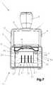
- a stamp 1in particular a tripod stamp 1 is shown, which comprises at least one stamp component 2 and an impression unit 3.
- the stamp component 2consists of at least one upper part 4 with a handle element 5 and a lower part 6 with a pad receiving element 7.
- the upper part 4is preferably bow-shaped and has a longitudinal web 8 and two side elements 9,10, wherein the side elements 9,10 in the lower part 6 are guided.
- the impression unit 3is connected via a turning mechanism 11, in the lower part 6 in motion-connected manner via an axis 12 or journal 12 to the upper part 4, so that the impression unit 3 in the lower part 6 of a rest position 13, according to Fig. 1 , in a printing or stamping position 14, according to Fig. 2 , by actuation of the upper part 4, in particular by pressurization of the handle element 5, can move.
- the upper part 4is cap-like and receives the lower part 6 in the interior during a stamping process, as is the case with plastic self-inking stamp, for example in "Printy 4.0" from Trodat.
- plastic self-inking stampfor example in "Printy 4.0" from Trodat.
- the rest position 12is mounted on the impression unit 3 text plate 15 on a soaked with stamp ink stamp pad 16 in the pad receiving element 7, wherein in a stamping process for generating a stamp impression the impression unit 3 with the text plate 15 via the turning mechanism 11 from the rest position 13 via a rotational movement in the die position 14 is adjustable or is adjusted, that is, that the impression unit 3 is rotated about the axis 12, including the turning mechanism 11 is provided, in which a predetermined cam track 17, a rotation of the impression unit 3 is completed.
- a combination of metal parts 18 and plastic parts 19is used, wherein the metal parts 18 are arranged externally visible.
- the metal partsare pushed over the plastic parts and engage via a latching connection (not shown), so that upon pressurization, the metal parts 18 take part of the pressure, ie, that the metal parts 18 support the plastic parts 19 in their stiffness, so no bending of Sharing is possible and thus an optimal impression with very high impression quality is achieved.
- the advantage of using a metal / plastic combinationis that the plastic parts can be dimensioned smaller in their wall thickness, since the metal parts 18 also receives a portion of the forces acting.
- the structure of the illustrated stamp 1takes place in the stamp component 2 in the form of a kit, ie, that the same parts of the stamp components 2 are used for a variety of versions of the stamp 1 such as tripod stamp 1 with a text plate as well as tripod stamp 1 with a MB unit (mounted-band set unit) 19, wherein the individualization takes place only by the onset of the impression unit 3.
- the MB unit 19can be inserted into the impression unit 3, wherein these are preferably guided on two sides via guide elements 20 on the impression unit 3, in particular a text plate carrier 21.
- the MB unit 19has a base body 22 and a closure element 23.
- the main body 22has a preferably round receiving element 24 and a so-called bridge 25.
- On the receiving element 24a plurality of belt drives 26, which are formed from an adjusting wheel 27 and a motion-coupled driver 28, respectively.
- each a stamping belt 29is arranged, wherein in the illustrated embodiment, the MB unit 19 is designed as a date, and thus four punch bands 29 (two daytime tapes, a monthly tape and a year tape) and four tape drives 26 on the receiving element 24th to be assembled.
- the punch bands 29are guided over the bridge 25, which is preferably adjustable, so that a corresponding band tension can be set up and adjusted. So that the belt drives 26 can not slip from the main body 22, then the End element 23 attached, which can be done for example with a latching connection.
- the end member 23is only plugged because the final element 23 can not slip from the main body 22 by the two guide elements 20, 21 by mounting on the impression unit 3.
- At least the driver 27 of the belt drive 26is formed from a two-component injection molded part, wherein a surface 30 of the driver 27 is formed of a material having high frictional properties for safe further transport of the punch belt 29.
- the punch band 29itself has on the side facing the driver 27 a smooth or slightly roughened surface, so that a frictional engagement for the transport of the punch belt 29 is provided via the driver 27.
- a transport system for the punch belt 29 for the stamp 1, in particular a tripod stampcreated that at least the belt drive 26, which consists of an adjusting element 27 with a motion-coupled driver 28 for the punch belt 29, and the so-called bridge 25 for deflecting and Positioning of the punch band 29 in the impression area comprises, wherein the driver 28 and the bridge 25 are positioned relative to each other such that the punch band 29 is held and stretched by them.
- the surface 30may have a structure which engages in a corresponding structure on the punch band 29, wherein due to the two-component injection molded parts, a high frictional engagement is formed, since the materials of the surface 30 is matched with the punch band material to to ensure a safe transport.
- a tape cover 31is provided, which is simply plugged, as in the prior art, in particular from AT 503570 B or the AT 504428 B , is known, so that it is not discussed further.
- a central height adjustment 32 for the MB unit 19is now provided in order to allow a simple and rapid adaptation of the MB unit 19.
- a central elementis a height adjustment element 33, according to Fig. 6 , which simultaneously serves for guiding and height adjustment 32 of the MB unit 19.
- the height adjustment element 33is connected to an adjusting element 34, in particular with a preferably centrally arranged adjusting screw 35, or stands with this in operative connection, so that by adjusting the adjusting element 34, the height adjustment element 33 is moved.
- the height adjustment 33has an angularly extending link track 36 and a horizontally extending guide track 37, wherein in the illustrated embodiment in each case two slide tracks 36 and guideways 37, which are laterally arranged or integrally formed on a central web 38.
- the guideways 37engage in guides 39 on the lateral guide elements 20, 21 of the impression unit 3 and the slide track 36 in corresponding guides 40 on the base body 22 and end member 23 of the MB unit 19 a. This ensures that the MB unit 19 is movably mounted on the angular slide track 36 for the height adjustment 32 and this is simultaneously guided over the guide track 37 in the horizontal direction of the impression unit 3.
- the adjusting element 34is actuated, whereby the height adjustment element 33 is displaced in the horizontal direction, i. that the central web 38 is in operative connection with the adjusting screw 35, so that by turning the adjusting screw 35, this is screwed or rotated and thus the central web 38 is also moved horizontally with the slide tracks 36 and guideways 37. Since the MB unit 19 is guided vertically in the guide elements 20, 21, this can not be moved horizontally, but slides along the angular slide track 36 in the vertical direction still up or down, depending on the rotational movement of the adjusting 35th
- the height adjustment 32it is essential in the height adjustment 32 according to the invention that this is now with only a single adjustment 34, in particular a single adjustment screw 35, to use, whereby a parallel displacement of the entire MB unit 19 to the text plate 15 via the angular slide track 36 takes place or is achieved ,
- a parallel displacement of the entire MB unit 19 to the text plate 15 via the angular slide track 36takes place or is achieved .
- the central height adjustment 32is arranged directly on the impression unit 3, so that it also performs a rotation in a stamping operation.
- a significant advantagelies in the fact that the access to the adjusting element 34, in particular the adjusting screw 35, takes place laterally, so that in the rest position 13 and in the position of the piston 14, the adjusting element 34 can be easily achieved, whereas in the prior art this is not the case because the usual two adjustment screws of Above, so in the range of Versteller 27 are arranged so that only in the rest position 13 from the bottom or in a half-stroke position of the side of the punch 1 access is possible.
- the adjusting element 34is not arranged in the center of the central web 38, but the adjusting elements 34 may be positioned in the side areas.
- the embodiment described abovecan be constructed in reverse, that is, that not MB unit 19 is adjusted in height, but that the text plate 15 or text plate carrier 21 is adjusted in height on the adjusting element 34. It is essential in the solution according to the invention that the support plate 15 or the text plate carrier 21, in particular a text plate mounting surface 41 and MB unit 19 are mutually adjustable in height, so that a corresponding adjustment can be performed. This is necessary insofar as different MB units 19 are used with different thickness stamping bands 29 or various text plates 15 made of different thicknesses of materials, especially rubber, so that a corresponding adjustment is necessary.
- the adjustmentthereby takes place via only one adjusting element 34, in particular a centrally disposed adjusting screw 35, whose accessibility over the longer free side of the punch 1, ie a front 42 or back 43, in the rest position 13 and in the stamp position 14 takes place.
- This accessibilityis essential insofar as it is possible for the first time, the punch 1 in the punch position 14, according to Fig. 2 to bring and make in this the adjustment, ie, that, for example, the punch 1 is brought into the punch position 14 and preferably locked, whereupon the front or back 42,43 the MB unit 19 is set, for which purpose the stamp can be placed on a surface, and then the MB unit 19 is added.
- the stamp maker or usergets set up stamp 1 on a table or a surface when adjusting a feedback, since the MB unit 19 is also pressed against the table or the surface, so that a corresponding stop is present and thus the stamp maker or User knows that now both components, so the text plate 15 and the MB unit 19 are on a same level or level.
- a further embodimentis shown, in which the height adjustment via a plurality, in particular two adjusting elements 34, 44, whereby these are preferably independently adjustable.
- an adjusting element 34, 44is arranged on each side of the MB unit 19, these now being designed as adjusting levers 45, 46, so that no additional tools, such as a screwdriver, are required for the adjustment.
- the adjusting lever 45,46the adjusting screws 35 can be used.
- the two adjustment 34,44are not in operative connection, but can independently perform a height adjustment of the MB unit 19 or text plate mounting surface 41 on each side of the MB unit 19, that is, the adjustment of the height of the MB unit 19 via the two adjusting elements 34,44, in which case stepwise on each side of the MB unit 19, these are raised or lowered to the text plate mounting surface 41 or vice versa.
- the MB unit 19With such a design with independent adjustment elements 34, 44, it is possible for the MB unit 19 to be aligned obliquely, in particular at an angle, to the text plate mounting surface 41. This is advantageous if an MB unit has 19 different punch bands 29, or the manufacturing tolerances in the punch bands 29 is very high, since then a corresponding oblique orientation can take place.
- the lifting and lowering of the MB unit 19may be via a spindle, eccentric, or other lifting mechanism that deflects the horizontal rotary motion into a vertical lifting motion, wherein it is essential that accessibility be in the rest position 13 and / or in the punch position 14 over the front 42 or back 43 or from both sides.
- Fig. 8an embodiment is shown in which the adjusting elements 34,44 again takes place via an angular cam tracks 36.
- the adjusting elements 34, 44are now arranged above or in the region of an upper side 47 of the MB unit 19 in the guide elements 20, which in turn however parallel to the text plate mounting surface 41, ie rotated by 90 ° to the punch direction of the MB unit 19, are arranged.
- the angular slide track 36is now arranged in a channel 48, in which the adjusting element 34, 44 engages.
- the adjusting element 34, 44is designed as an adjusting screw 35, 49, wherein the adjusting screws 35, 49 have a corresponding angled surface 50.
- the MB unit 19for this purpose with a height adjustment 51, which in the guide elements 20th is guided, connected and in which the channel 48 is arranged. So that a height adjustment of the MB unit 19 is possible, the height adjustment element 51 has a slot 52 for the axis 12.
- the channel 48is arranged with the angular slide track 36 directly to the MB unit 19, so that the MB unit 19 is inserted into the guide elements 20. Subsequently, the adjusting screws 35,49 are screwed via a provided with a thread 53 bore 54 in the guide member 20, so that the adjusting screws 35, 49 engage in the channel 48.
- the MB unit 19is supported by a spring member (not shown), so that the MB unit 19 is always urged in a certain direction. This ensures that when adjusting the adjusting elements 34, 44, the MB unit 19 is pressed against the angular slide track 36, so that an optimal displacement along the slide track 36 is possible. Both training with tension spring or compression spring is possible.
- Fig. 9is a kind of exploded view of the most important elements for an embodiment of an adjustment of the text plate carrier 21 shown with a central height adjustment 32, ie that now the MB unit 19 is fixed and upon actuation of the adjusting element 34 of the text plate carrier 21 to the MB unit 19 in height is adjusted.
- the base body 22 and the closing element 23 in the region of the bridge 25has a bore 55 for the axis 12.
- the MB unitis fixed in the assembled state, as through the bore 55 no more displacement is possible.
- the MB unit 19, in particular the base body 22 and the closing element 23was equipped with a slot for the height adjustment.
- a corresponding elongated hole 56is now arranged on the text plate carrier 21, so that the entire text plate carrier 21 can be adjusted via the adjusting element 34 to the MB unit 19 in height.
- Fig. 10an embodiment is shown in which the MB unit 19 is resiliently mounted on the text plate carrier 21 of the impression unit 3.
- a spring element 57is arranged such that it presses the MB unit 19 in a certain direction, so that there is always a defined position of the MB unit 19.
- a compression springis used as a spring element 57, which presses the MB unit 19 in the direction of the text plate mounting surface 41.
- the MB unit 19can now be placed beyond the text plate 15 (not shown) in the case of the height adjustment 32, since during a stamping operation the MB unit 19 builds up an additional pressure via the spring element 57.
- the height adjustment 32does not have to be carried out exactly, since an independent adaptation is carried out via the spring element 57.
Landscapes
- Manufacture Or Reproduction Of Printing Formes (AREA)
- Handling Of Sheets (AREA)
- Shaping Of Tube Ends By Bending Or Straightening (AREA)
- Printers Characterized By Their Purpose (AREA)
Description
Translated fromGermanDie Erfindung betrifft einen Stempel und eine Abdruckeinheit, wie sie in den Oberbegriffen der Ansprüche 1 und 8 beschrieben sind.The invention relates to a stamp and an impression unit, as described in the preambles of claims 1 and 8.
Aus der
Ein derartiger Aufbau eines Stativ-Stempels von der Anmelderin weist im Gegensatz zum weiteren Stand der Technik, wie beispielsweise der
Die bei dem vorgenannten Dokumenten verwendete Abdruckeinheit mit daran befestigten MB-Einheit (Montierter Bänder Einheit) ist derart ausgebildet, dass die MB-einheit über zumindest zwei Verstellelemente, insbesondere Schrauben, in ihrer Höhe zur Textplatte verstellt wird. Nachteilig ist hierbei, dass eine voneinander unabhängige Verstellung der Verstellelemente durchgeführt werden muss, sodass es sehr oft der Fall ist, dass die MB-Einheit nicht parallel zur Textplatte ausgerichtet ist. Dadurch kann es zu unterschiedlichen Abdruckbildern kommen.The printing unit used in the aforementioned documents with attached MB unit (assembled tape unit) is designed such that the MB unit is adjusted over at least two adjusting elements, in particular screws, in height to the text plate. The disadvantage here is that an independent adjustment of the adjustment must be performed so that it is often the case that the MB unit is not aligned parallel to the text plate. This can lead to different imprints.
Die Aufgabe der Erfindung liegt darin, einen Stempel, eine Abdruckeinheit, eine Abdruckplatte für eine Abdruckeinheit zu schaffen, bei dem eine verbesserte Einstellmöglichkeit der Höhe für die Stempelbänder erzielt wird. Gleichzeitig soll eine einfacher Anpassbarkeit und Montage der Textplatte geschaffen werden. Eine weitere Aufgabe liegt darin, eine möglichst späte Individualisierung des Stempels zu ermöglichen.The object of the invention is to provide a stamp, an impression unit, an impression plate for an impression unit, in which an improved adjustment of the height for the punch bands is achieved. At the same time a simple adaptability and installation of the text plate should be created. Another task is to allow as late as possible individualization of the stamp.
Die Aufgabe der Erfindung wird durch einen Stempel derart gelöst, dass das Höhenverstellelement mit einem einzigen Verstellelement, insbesondere einer vorzugsweisen zentral angeordneten Verstellschraube, verbunden ist bzw. mit diesem in Wirkverbindung steht und die MB-Einheit und/oder Textplattenträger über das Höhenverstellelement am Textplattenträger und/oder MB-Einheit befestigt ist. Vorteilhaft ist hierbei, dass dadurch eine sehr einfache Höhenverstellung über nur ein Verstellelement geschaffen wurde. Dadurch kann eine sehr rasche Anpassung der MB-Einheit durch einfaches Verdrehen des Verstellelementes erfolgen. Durch die seitliche Anordnung des Verstellelementes wird auch die Zugänglichkeit wesentlich erhöht, das es nunmehr möglich ist, die MB-Einheit in der Ruheposition als auch in der Stempelposition einzustellen. Zur Höheneinstellung der MB-Einheit wird bevorzugt der Stempel mit der Textplatte in die Stempelstellung verbracht, sodass anschließend der Stempelmacher oder Nutzer durch einfaches Verdrehen des Verstellelementes die MB-Einheit anpassen kann. Ein weiterer wesentlicher vorteilhafte Ausbildung liegt darin, dass damit immer eine parallele Verstellung der MB-Einheit über das Höhenverstellelement durchgeführt wird, wogegen beim Stand der Technik mit zwei Einstellschrauben sehr häufig eine schiefe Ausrichtung der MB-Einheit erfolgt, wodurch die Stempelqualität verschlechtert wird. Wesentlich ist bei der Höhenverstellung, dass die MB-Einheit und Textplattenträger zueinander verstellt wird, um eine Anpassung der Beiden vornehmen zu können, d.h., dass die beschriebenen Ausführungsbeispiele auch für die Verstellung des Textplattenträgers bei fixer MB-Einheit verwendet werden kann.The object of the invention is achieved by a stamp such that the height adjustment is connected to a single adjustment, in particular a preferably centrally located adjusting screw, or is in operative connection with this and the MB unit and / or text plate carrier on the height adjustment on the text plate carrier and or MB unit is attached. The advantage here is that this has created a very simple height adjustment over only one adjustment. This allows a very rapid adaptation of the MB unit done by simply rotating the adjustment. By the lateral arrangement of the adjusting element and the accessibility is significantly increased, it is now possible to set the MB unit in the rest position and in the stamp position. For height adjustment of the MB unit, the stamp is preferably spent with the text plate in the stamp position, so that then the stamp maker or user can adjust the MB unit by simply turning the adjustment. Another significant advantageous embodiment is that it always performs a parallel adjustment of the MB unit on the height adjustment, whereas in the prior art with two screws very often an oblique orientation of the MB unit is done, whereby the stamp quality is deteriorated. It is essential in the height adjustment that the MB unit and text plate carrier is adjusted to each other to make an adjustment of the two, ie, that the embodiments described can also be used for the adjustment of the text plate carrier with a fixed MB unit.
Es ist eine Ausbildung von Vorteil, bei der die MB-Einheit über zumindest eine, bevorzugt zwei Führungselemente an der Abdruckeinheit frei beweglich geführt ist. Vorteilhaft ist hierbei, dass dadurch eine einfache Höhenverstellung durch die frei bewegliche Lagerung in vertikaler Richtung möglich ist, jedoch gleichzeitig in horizontaler Richtung eine Verschiebung der MB-Einheit unterbunden wird.It is an embodiment of advantage in which the MB unit is guided freely movable on at least one, preferably two guide elements on the impression unit. The advantage here is that thereby a simple height adjustment by the freely movable mounting in the vertical direction is possible, but at the same time a displacement of the MB unit is prevented in the horizontal direction.
Eine weitere Ausbildung ist von Vorteil, bei der das Verstellelement durch eine Verstellschraube gebildet ist und diese bevorzugt im Zentrum, insbesondere in dem Mittebereich des Höhenverstellelementes, insbesondere eines Zentralsteges angeordnet ist. Dadurch wird erreicht, dass durch einfaches Drehen der Verstellschraube die Höhenverstellung der MB-Einheit vorgenommen werden kann. Die Zugänglichkeit zur Verstellschraube wird durch die zentrale Positionierung ebenfalls verbessert. Es ist aber auch möglich, dass die Verstellschraube durch ein aliquotes Mittel, insbesondere einen Verstellhebel, ersetzt wird, der beispielsweise einfach verdreht wird, um die MB-Einheit in der Höhe zu verstellen.A further embodiment is advantageous, in which the adjusting element is formed by an adjusting screw and this is preferably arranged in the center, in particular in the middle region of the height adjustment element, in particular a central web. This ensures that the height adjustment of the MB unit can be made by simply turning the adjusting screw. The accessibility to the adjusting screw is also improved by the central positioning. But it is also possible that the adjusting screw is replaced by an aliquotes means, in particular an adjusting lever, which is for example simply twisted to adjust the height of the MB-unit.
Vorteilhaft ist eine Ausbildung, bei der das Höhenverstellelement eine winkelig verlaufende Kulissenbahn aufweist. Dadurch wird erreicht, dass die MB-Einheit entlang der winkeligen Kulissenbahn in der Höhe verstellt wird, wenn das Höhenverstellelement horizontal über das Verstellelement verschoben wird. Durch die entsprechende Ausbildung des Winkels für die Kulissenbahn kann auf die Verstellhöhe bzw. Empfindlichkeit Einfluss genommen werden, d.h., dass bei einem flacheren Winkel der Kulissenbahn eine geringer Höheanpassung möglich, als bei einem steileren Winkel. Somit kann je nach Ausbildung der Abdruckeinheit ein entsprechendes Höhenverstellelement mit korrespondierender MB-Einheit eingesetzt werden.An embodiment in which the height adjustment element has an angularly extending slide track is advantageous. This ensures that the MB unit is adjusted along the angular slide track in height when the height adjustment is moved horizontally over the adjustment. By the appropriate design of the angle for the slide track can be influenced on the adjustment height or sensitivity, that is, at a shallower angle of the slide track, a lower height adjustment possible than at a steeper angle. Thus, depending on the design of the impression unit, a corresponding height adjustment element with a corresponding MB unit can be used.
Es ist aber auch eine Ausbildung von Vorteil, bei der das Höhenverstellelement eine Führungsbahn zur horizontalen Führung aufweist. Dadurch wird erreicht, dass bei der Verstellung über die winkelige Kulissenbahn eine sichere horizontale Führung vorhanden ist, um ein Verkanten der Höhenverstellelement zu vermeiden. Selbstverständlich kann das Höhenverstellelement auch nur mit der winkeligen Kulissenbahn eingesetzt werden. Vorteilhaft ist eine Ausbildung, bei der die MB-Einheit über das Höhenverstellelement befestigt und verstellbar ist. Dadurch wird erreicht, dass eine einfache und rasche Montage ermöglicht ist und keine zusätzlichen Befestigungsmittel eingesetzt werden müssen.But it is also an embodiment of advantage in which the height adjustment element has a guideway for horizontal guidance. This ensures that in the adjustment via the angular slide track safe horizontal guidance is present in order to avoid tilting of the height adjustment. Of course, the height adjustment can also be used only with the angular slide track. An advantageous embodiment is that the MB unit is fastened and adjustable via the height adjustment element. This ensures that a simple and quick installation is possible and no additional fasteners must be used.
Bei einer Ausbildung ist von Vorteil, dass die Höhenverstellelement bügelförmig ausgebildet ist, wobei bevorzugt an beiden Seiten eines Zentralsteg (38) die winkelige Kulissenbahn (36) und die horizontale Führungsbahn (37) angeordnet sind. Dadurch wird erreicht, dass eine parallele Verschiebung der MB-Einheit zur Textplatte sichergestellt ist.In one embodiment, it is advantageous that the height adjustment element is bow-shaped, wherein the angular slide track (36) and the horizontal guide track (37) are preferably arranged on both sides of a central web (38). This ensures that a parallel shift of the MB unit to the text plate is ensured.
Die Aufgabe der Erfindung wird aber auch durch eine Abdruckeinheit gelöst, bei der das Höhenverstellelement mit einem Verstellelement, insbesondere einer bevorzugt zentral angeordneten Verstellschraube, verbunden ist bzw. mit diesem in Wirkverbindung steht, wobei die MB-Einheit über das Höhenverstellelement am Textplattenträger und/oder MB-Einheit befestigt ist.
Vorteilhaft ist hierbei, dass durch einen derartigen Aufbau ein einfache und rasche Verstellung in allen Lagen, insbesondere in der Stempelstellung, möglich ist. Gleichzeitig kann durch den Aufbau einer derartigen Abdruckeinheit diese in die unterschiedlichsten Stempel wie beispielsweise Stativ-Stempel, Kunststoff Selbst-Färbestempel, eingesetzt werden. Bevorzugt wird dabei das Verstellelement seitlich zentral unterhalb der Verstellelemente für die Stempelbänder angeordnet, um die Best mögliche Zugänglichkeit zu erreichen.The object of the invention is also achieved by an impression unit, wherein the height adjustment is connected to an adjusting element, in particular a preferably centrally disposed adjusting screw, or is in operative connection with the latter, wherein the MB unit on the height adjustment on the text plate carrier and / or MB unit is attached.
It is advantageous in this case that a simple and rapid adjustment in all positions, in particular in the stamp position, is possible by such a construction. At the same time can be used by the construction of such an impression unit in a variety of stamps such as tripod stamp, plastic self-inking. Preferably, the adjusting element is arranged laterally centrally below the adjusting elements for the punch bands in order to achieve the best possible accessibility.
Es ist eine Ausbildung von Vorteil, bei der die Abdruckeinheit mit der MB-Einheit nachträglich in eine Stempelkomponente eines Stempels anordenbar ist und diese zur parallelen Höhenverstellung der MB-Einheit in einem Stempel, insbesondere Stativ-Stempel, ausgebildet ist. Dadurch wird erreicht, dass die Stempelkomponente unabhängig der einzusetzenden Abdruckeinheit gefertigt werden kann, sodass eine möglichst späte Individualisierung stattfindet. Dies ist insofern möglich, da für die Höhenverstellung der MB-Einheit sämtlich Teile bzw. Komponenten auf der Abdruckeinheit angeordnet sind, sodass diese unabhängig vom Stempel einsatzbereit ist.It is an embodiment of advantage in which the impression unit with the MB unit can be subsequently arranged in a stamp component of a stamp and this is for parallel height adjustment of the MB unit in a stamp, in particular tripod stamp formed. This ensures that the stamp component can be manufactured independently of the impression unit to be used, so that as late as possible individualization takes place. This is possible insofar as for the height adjustment of the MB unit all parts or components are arranged on the impression unit, so that it is ready for use independently of the punch.
Es sind weitere Ausbildungen in den Ansprüchen 1 bis 7 beschrieben. Die sich daraus ergebenden Vorteile können aus der Beschreibung, insbesondere aus den Vorteilen zum Stempel, entnommen werden.There are further embodiments described in claims 1 to 7. The resulting advantages can be taken from the description, in particular from the benefits to the stamp.
Die Erfindung wird anschließend in Form von Ausführungsbeispielen beschrieben, wobei darauf hingewiesen wird, dass die Erfindung nicht auf die dargestellten und beschriebenen Ausführungsbeispiele bzw. Lösungen begrenzt ist.The invention will now be described in the form of embodiments, it being understood that the invention is not limited to the illustrated and described embodiments or solutions.
Es zeigen:
- Fig.1
- eine schaubildliche Darstellung eines Stempel, insbesondere eines Stativstempels, in einer Ruhestellung; in vereinfachter, schematischer Darstellung;
- Fig.2
- eine schaubildliche Darstellung des Stempel in einer Druck- bzw. Stempelstellung; in vereinfachter, schematischer Darstellung;
- Fig.3
- eine Vorderansicht einer Abdruckeinheit mit eingesetzte MB-Einheit und zentraler Höhenverstellung, in vereinfachter, schematischer Darstellung;
- Fig.4
- eine Schnittansicht der Abdruckeinheit nach
Fig. 3 , in vereinfachter, schematischer Darstellung; - Fig.5
- eine schaubildliche Darstellung eines Höhenverstellelementes für die MB-Einheit, in vereinfachter, schematischer Darstellung;
- Fig.6
- eine Explosion - Darstellung der Abdruckeinheit, in vereinfachter, schematischer Darstellung;
- Fig.7
- eine Rückansicht des Stempels mit zwei Verstellelementen, in vereinfachter, schematischer Darstellung;
- Fig.8
- eine weiteres Ausführungsbeispiel einer Höhenverstellung mit zwei Verstellelementen, in vereinfachter, schematischer Darstellung;
- Fig.9
- eine Ausführungsbeispiel mit einer Verstellung des Textplattenträger ohne montierten Stempelbänder, in vereinfachter, schematischer Darstellung;
- Fig.10
- ein Ausführungsbeispiel mit federnd gelagerter MB-Einheit, in vereinfachter, schematischer Darstellung.
- Fig.1
- a perspective view of a stamp, in particular a tripod stamp, in a rest position; in a simplified, schematic representation;
- Fig.2
- a perspective view of the stamp in a print or stamp position; in a simplified, schematic representation;
- Figure 3
- a front view of an impression unit with inserted MB unit and central height adjustment, in a simplified, schematic representation;
- Figure 4
- a sectional view of the impression unit according to
Fig. 3 , in simplified, schematic representation; - Figure 5
- a perspective view of a height adjustment for the MB unit, in a simplified, schematic representation;
- Figure 6
- an explosion - representation of the impression unit, in a simplified, schematic representation;
- Figure 7
- a rear view of the punch with two adjusting elements, in a simplified, schematic representation;
- Figure 8
- a further embodiment of a height adjustment with two adjusting elements, in a simplified, schematic representation;
- Figure 9
- an embodiment with an adjustment of the text plate carrier without mounted punch bands, in a simplified, schematic representation;
- Figure 10
- an embodiment with spring-mounted MB unit, in a simplified, schematic representation.
Einführend sei festgehalten, dass in den unterschiedlichen Ausführungsformen gleiche Teile mit gleichen Bezugszeichen bzw. gleichen Bauteilbezeichnungen versehen werden, wobei die in der gesamten Beschreibung enthaltenen Offenbarungen sinngemäß auf gleiche Teile mit gleichen Bezugszeichen bzw. gleichen Bauteilbezeichnungen übertragen werden können. Auch sind die in der Beschreibung gewählten Lageangaben, wie z.B. oben, unten, seitlich usw. auf die beschriebene Figur bezogen und sind bei einer Lageänderung sinngemäß auf die neue Lage zu übertragen. Auch können Einzelmerkmale oder Merkmalskombinationen aus den gezeigten und beschriebenen Ausführungsbeispielen für sich eigenständige erfinderische Lösungen darstellen.By way of introduction, it should be noted that in the various embodiments, the same parts are provided with the same reference numerals or the same component names, wherein the disclosures contained in the entire description can be mutatis mutandis to the same parts with the same reference numerals and component names. Also, the location selected in the description, such as top, bottom, side, etc. related to the described figure and are mutatis mutandis transferred to the new situation in a change in position. Also, individual features or combinations of features from the illustrated and described embodiments may represent separate inventive solutions.
In den
Die Stempelkomponente 2 besteht zumindest aus einem Oberteil 4 mit einem Griffelement 5 und einem Unterteil 6 mit einem Kissenaufnahmeelement 7. Der Oberteil 4 ist bevorzugt bügelförmig ausgebildet und weist ein Längssteg 8 und zwei Seitenelementen 9,10 auf, wobei die Seitenelemente 9,10 im Unterteil 6 geführt sind. Die Abdruckeinheit 3 ist über einen Wendemechanismus 11, im Unterteil 6 bewegungsverbunden über eine Achse 12 bzw. Achszapfen 12 mit dem Oberteil 4 verbunden, sodass sich die Abdruckeinheit 3 im Unterteil 6 von einer Ruheposition 13, gemäß
Bei dem dargestellten Stempel 1 wird eine Kombination aus Metallteilen 18 und Kunststoffteilen 19 verwendet, wobei die Metallteile 18 außen sichtbar angeordnet sind. Die Metallteile werden dabei über die Kunststoffteile geschoben und rasten über eine Rastverbindung (nicht dargestellt) ein, sodass bei einer Druckbeaufschlagung die Metallteile 18 einen Teil des Druckes aufnehmen, d.h., dass die Metallteile 18 die Kunststoffteile 19 in ihrer Steifigkeit unterstützen, sodass kein Verbiegen von Teilen möglich ist und somit ein optimaler Abdruck mit sehr hoher Abdruckqualität erzielt wird. Der Vorteil für den Einsatz einer Metall/Kunststoff-Kombination liegt darin, dass die Kunststoffteile in ihrer Wandstärke geringer dimensioniert werden können, da die Metallteile 18 ebenfalls einen Teil der einwirkenden Kräfte aufnimmt.In the illustrated stamp 1, a combination of
Der Aufbau des dargestellten Stempels 1 erfolgt bei der Stempelkomponente 2 in Form eines Baukasten, d.h., dass gleiche Teile der Stempelkomponenten 2 für die unterschiedlichsten Ausführungen des Stempels 1 verwendet werden wie beispielsweise Stativ-Stempel 1 mit einer Textplatte als auch Stativ-Stempel 1 mit einer MB-Einheit (Montierten-Bändersatz-Einheit) 19, wobei die Individualisierung erst durch das einsetzten der Abdruckeinheit 3 erfolgt.The structure of the illustrated stamp 1 takes place in the
Hierzu kann die MB-Einheit 19 in die Abdruckeinheit 3 eingesetzt werden, wobei diese bevorzugt auf zwei Seiten über Führungselemente 20 an der Abdruckeinheit 3, insbesondere einem Textplattenträger 21, geführt sind. Die MB-Einheit 19 weist hierzu ein Grundkörper 22 und ein Abschlusselement 23 auf. Der Grundkörper 22 weist eine vorzugsweise runde Aufnahmeelement 24 und eine sogenannte Brücke 25 auf. An dem Aufnahmeelement 24 sind mehrere Bandantriebe 26, die aus einem Verstellrad 27 und einem bewegungsgekoppelten Mitnehmer 28 gebildet sind, angeordnet. Am Mitnehmer 27 des Bandantriebes 26 ist jeweils ein Stempelband 29 angeordnet, wobei bei dem dargestellten Ausführungsbeispiel die MB-Einheit 19 als Datum ausgeführt ist, und somit vier Stempelbänder 29 (zwei Tagesbänder, ein Monatsband und ein Jahresband) und vier Bandantriebe 26 am Aufnahmeelement 24 montiert werden. Die Stempelbänder 29 werden dabei über die Brücke 25, die vorzugsweise verstellbar ausgebildet ist, geführt, sodass eine entsprechende Bandspannung aufgebaut und eingestellt werden kann. Damit die Bandantriebe 26 nicht vom Grundkörper 22 rutschen können, wird anschließend das Abschlusselement 23 aufgesteckt, was beispielsweise mit einer Rastverbindung erfolgen kann. Vorzugsweise wird das Abschlusselement 23 nur aufgesteckt, da durch die Montage an der Abdruckeinheit 3 das Abschlusselement 23 nicht vom Grundkörper 22 durch die beiden Führungselemente 20, 21 rutschen kann.For this purpose, the
Vorzugsweise ist zumindest der Mitnehmer 27 des Bandantriebes 26 aus einem Zweikomponenten-Spritzgussteil gebildet, wobei eine Oberfläche 30 des Mitnehmer 27 aus einem Material mit hohen Reibschluss-Eigenschaften zum sicheren Weitertransport des Stempelbandes 29 ausgebildet ist. Das Stempelband 29 selbst weist auf der dem Mitnehmer 27 zugewandten Seite eine glatte bzw. leicht aufgeraute Oberfläche auf, sodass ein Reibschluss für den Transport des Stempelbandes 29 über den Mitnehmer 27 geschaffen wird. Dadurch wird ein Transportsystem für das Stempelband 29 für den Stempel 1, insbesondere einen Stativ-Stempel geschaffen, das zumindest den Bandantrieb 26, der aus einem Verstellelement 27 mit einem bewegungsgekoppelten Mitnehmer 28 für das Stempelband 29 besteht, und der sogenannten Brücke 25 zum Umlenken und Positionieren des Stempelbandes 29 im Abdruckbereich umfasst, wobei der Mitnehmer 28 und die Brücke 25 derart zueinander Positioniert sind, dass das Stempelband 29 von diesen gehalten und gespannt ist. Selbstverständlich ist es auch möglich, dass die Oberfläche 30 eine Struktur aufweisen kann, die in eine korrespondierende Struktur am Stempelband 29 eingreift, wobei aufgrund der Zweikomponenten-Spritzgussteile ein hoher Reibschluss gebildet wird, da die Materialien der Oberfläche 30 mit dem Stempelbandmaterial abgestimmt ist, um einen sicheren Transport zu gewährleisten.Preferably, at least the
Bei dem dargestellten Ausführungsbeispiel ist eine Bandabdeckung 31 vorgesehen, die einfach aufgesteckt wird, wie es aus dem Stand der Technik, insbesondere aus der
Bei der erfinderischen Abdruckeinheit 2 ist nunmehr eine zentrale Höhenverstellung 32 für die MB-Einheit 19 vorgesehen, um eine einfach und rasche Anpassung der MB-Einheit 19 zu ermöglichen. Als zentrales Element ist hierzu ein Höhenverstellelement 33, gemäß
Zum Verstellen des Höhenverstellelementes 33 ist es erforderlich, dass das Verstellelement 34 betätigt wird, wodurch das Höhenverstellelement 33 in horizontaler Richtung verschoben wird, d.h. dass der Zentralsteg 38 in Wirkverbindung mit der Verstellschraube 35 steht, sodass durch Drehen der Verstellschraube 35 diese eingeschraubt bzw. herausgedreht wird und somit der Zentralsteg 38 mit den Kulissenbahnen 36 und Führungsbahnen 37 ebenfalls horizontal mitbewegt wird. Da die MB-Einheit 19 senkrecht in den Führungselemente 20, 21 geführt ist, kann diese nicht horizontal verschoben werden, sondern gleitet entlang der winkeligen Kulissenbahn 36 in senkrechter Richtung noch oben oder unten, je nach Drehbewegung der Verstellschraube 35.To adjust the
Wesentlich bei der erfindungsgemäßen Höhenverstellung 32 ist, dass diese nunmehr mit nur einem einzigen Verstellelement 34, insbesondere einer einzigen Verstellschraube 35, zu bedienen ist, wodurch eine Parallelverschiebung der gesamten MB-Einheit 19 zur Textplatte 15 über die winkelige Kulissenbahn 36 erfolgt bzw. erzielt wird. Dadurch ist es erstmals möglich, dass bei einem Stempel 1 mit einem Wendemechanismus 11 mit nur einer Verstellschraube 35 eine Anpassung der Höhe für die MB-Einheit 19 vorgenommen werden kann. Dabei ist die zentrale Höhenverstellung 32 direkt auf der Abdruckeinheit 3 angeordnet, sodass diese bei einem Stempelvorgang ebenfalls eine Drehung vollzieht. Ein wesentlicher Vorteil liegt auch darin, dass der Zugang zum Verstellelement 34, insbesondere der Verstellschraube 35, seitlich erfolgt, sodass in der Ruhestellung 13 und in der Stempelstellung 14 das Verstellelement 34 leicht erreicht werden kann, wogegen beim Stand der Technik dies nicht der Fall ist, da die üblichen zwei Einstellschrauben von Oben, also im Bereich der Verstellräder 27 angeordnet sind, sodass nur in der Ruhestellung 13 von unten oder in einer halben Stempelstellung von der Seite des Stempels 1 der Zugang möglich ist.It is essential in the
Selbstverständlich ist es möglich, dass das Verstellelement 34 nicht im Zentrum des Zentralsteges 38 angeordnet wird, sondern das Verstellelemente 34 auch in den Seitenbereichen positioniert sein kann.Of course, it is possible that the adjusting
Weiters ist es aber auch möglich, dass das zuvor beschriebenen Ausführungsbeispiel umgekehrt aufgebaut werden kann, d.h., dass nicht MB-Einheit 19 in der Höhe verstellt wird, sondern das die Textplatte 15 bzw. Textplattenträger 21 in der Höhe über das Verstellelement 34 verstellt wird. Wesentlich bei der erfindungsgemäße Lösung ist, dass die Trägerplatte 15 bzw. der Textplattenträger 21, insbesondere eine Textplatten-Montagefläche 41 und MB-Einheit 19 in der Höhe zueinander einstellbar sind, sodass eine entsprechende Anpassung durchgeführt werden kann. Dies ist insofern notwendig, da unterschiedliche MB-Einheiten 19 mit unterschiedlich dicken Stempelbändern 29 oder verschiedenste Textplatten 15 aus unterschiedlich dicken Materialien, insbesondere Gummi, verwendet werden, sodass eine entsprechende Anpassung notwendig ist.Furthermore, it is also possible that the embodiment described above can be constructed in reverse, that is, that not
Wie beschrieben, erfolgt bei dem ersten Ausführungsbeispiel die Verstellung dabei über nur ein Verstellelement 34, insbesondere eine zentral angeordnete Verstellschraube 35, deren Zugänglichkeit über die längere freie Seite des Stempels 1, also einer Vorderseite 42 oder Rückseite 43, in der Ruhestellung 13 als auch in der Stempelposition 14 erfolgt. Dies Zugänglichkeit ist insofern wesentlich, da es erstmals möglich ist, den Stempel 1 in die Stempelposition 14, gemäß
In den
Dabei ist auf jeder Seite der MB-Einheit 19 ein Verstellelement 34, 44 angeordnet, wobei diese nunmehr als Verstellhebel 45,46 ausgebildet sind, sodass für die Verstellung keine zusätzlichen Werkzeuge, wie beispielsweise einen Schraubenzieher benötigt werden. Selbstverständlich ist es aber auch möglich, anstelle der Verstellhebel 45,46 das Verstellschrauben 35 eingesetzt werden können. Bevorzugt stehen die beiden Verstellelement 34,44 dabei nicht in Wirkverbindung, sondern können unabhängig voneinander auf jeder Seite der MB-Einheit 19 eine Höhenverstellung der MB-Einheit 19 oder Textplatten-Montagefläche 41 durchführen, d.h., dass die Einstellung der Höhe der MB-Einheit 19 über die beiden Verstellelemente 34,44 erfolgt, wobei hierbei schrittweise auf jeder Seite der MB-Einheit 19 diese zu der Textplatten-Montagefläche 41 angehoben oder abgesenkt werden oder umgekehrt. Bei einer derartigen Ausbildung mit unabhängigen Verstellelemente 34,44 ist es möglich, dass die MB-Einheit 19 nun schief, insbesondere winkelig, zu der Textplatten-Montagefläche 41 ausgerichtet werden kann. Dies ist dann von Vorteil, wenn eine MB-Einheit 19 unterschiedliche Stempelbänder 29 aufweist, bzw. die Herstellungstoleranzen bei dem Stempelbänder 29 sehr hoch ist, da dann ein entsprechende schiefe Ausrichtung erfolgen kann.In this case, an adjusting
Wesentlich ist gegenüber dem Stand der Technik, dass nunmehr erstmals die Verstellelemente 34, 44 über die Vorder- bzw. Rückseite 42,43 des Stempels 1 in der Ruhestellung 13 oder in der Stempelstellung 14 erfolgt, sodass eine sehr einfach Zugänglichkeit in den vorhandenen Positionen, gegeben ist und nicht eine zusätzliche Einstellungsposition benötigt wird, in der der Stempel 1 nur halb zusammen gedrückt wird, sodass die Zugänglichkeit zur Oberseite der MB-Einheit 19 über die Vorderseite 42 bzw. Rückseite 43 möglich ist, wozu bevorzugt hierzu eine eigene Sperrposition angeordnet ist, wie dies der Stand der Technik verwirklicht, da im Stand der Technik die Verstellelement an der Oberseite angeordnet und zugänglich sind.It is essential over the prior art, that now for the first time the
Bei dem dargestellten Ausführungsbeispiel der
In
Selbstverständlich ist es möglich, dass der Kanal 48 mit der winkeligen Kulissenbahn 36 direkt an der MB-Einheit 19 angeordnet ist, sodass die MB-Einheit 19 in die Führungselemente 20 eingesteckt wird. Anschließend werden die Verstellschrauben 35,49 über ein mit einem Gewinde 53 versehene Bohrung 54 in den Führungselement 20 eingeschraubt, sodass die Verstellschrauben 35, 49 in den Kanal 48 eingreifen.Of course, it is possible that the
Vorzugsweise ist die MB-Einheit 19 über ein Federelement (nicht dargestellt) gelagert, sodass die MB-Einheit 19 immer in eine bestimmte Richtung gedrückt wird. Dadurch wird erreicht, dass beim Verstellen über die Verstellelemente 34, 44 die MB-Einheit 19 gegen die winkelige Kulissenbahn 36 gedrückt wird, sodass eine optimale Verschiebung entlang der Kulissenbahn 36 möglich ist. Dabei ist sowohl eine Ausbildung mit Zugfeder oder Druckfeder möglich.Preferably, the
In
Wie nun aus den einzelnen Elementen zu ersehen ist, weist der Grundkörper 22 und das Abschlusselement 23 im Bereich der Brücke 25 ein Bohrung 55 für die Achse 12 auf. Damit ist die MB-Einheit im montierten Zustand fixiert, da durch die Bohrung 55 keine Verschiebung mehr möglich ist. Bei den zuvor beschriebenen Ausführungsbeispiel war die MB-Einheit 19, insbesondere der Grundkörper 22 und das Abschlusselement 23 mit einem Langloch für die Höhenverstellung ausgestattet. Ein entsprechendes Langloch 56 ist nunmehr am Textplattenträger 21 angeordnet, sodass der gesamte Textplattenträger 21 über das Verstellelement 34 an die MB-Einheit 19 der Höhe nach angepasst werden kann.As can now be seen from the individual elements, the
In
Bei dem gezeigte Ausführungsbeispiel wird dabei eine Druckfeder als Federelement 57 eingesetzt, die die MB-Einheit 19 in Richtung zur Textplatten-Montagefläche 41 drückt. Dadurch kann nunmehr bei der Höheneinstellung 32 die MB-Einheit 19 über die Textplatte 15 (nicht dargestellt) hinaus gestellt werden, da bei einem Stempelvorgang die MB-Einheit 19 über das Federelement 57 einen zusätzlich Druck aufbaut. Somit muss die Höheneinstellung 32 nicht exakt ausgeführt werden, da eine selbstständige Anpassung über das Federelement 57 durchgeführt wird.In the embodiment shown, a compression spring is used as a
Selbstverständlich ist es möglich, dass auch die zuvor beschriebenen Ausführungsvarianten mit einem entsprechenden Federelement 57 ausgestattet werden kann. Auch ist es möglich, dass bei entsprechender Konstruktion eine Zugfeder eingesetzt werden kann.Of course, it is possible that the previously described embodiments can be equipped with a
Der Ordnung halber sei abschließend darauf hingewiesen, dass zum besseren Verständnis des Aufbaus des Systems 1 und deren Komponenten bzw. dessen Bestandteile teilweise unmaßstäblich und/oder vergrößert und/oder verkleinert dargestellt wurden.For the sake of order, it should finally be pointed out that for a better understanding of the construction of the system 1 and its components or their components, they have been shown partially unevenly and / or enlarged and / or reduced in size.
Claims (15)
- Stamp (1) comprising at least one stamping component (2) and one stamping insert (3) with a mounted band unit (19), wherein the stamping component (2) comprises a top part (4) and a bottom part (6) with a cushion-receiving element (7), wherein the stamping insert (3) with the mounted band unit (19) is connected so as to move synchronously via a reversing mechanism (11) in the bottom part (6) to the top part (4), wherein in the resting position (13) a text plate (15) mounted on the stamping insert (3) and a stamping area of the mounted band unit (19) abut against an ink pad soaked with stamp ink (16) in the cushion-receiving element (7), and during a stamping process for producing a stamp impression the stamping insert (3), in particular with a mounted text plate (15) and the mounted band unit (19), can be shifted via the reversing mechanism (11) into a stamping position (14), wherein on the stamping insert (3) a height adjustment element (33) for the mounted band unit (19) and / or a text plate carrier (21) is provided,characterised in that the height adjustment element (33) is connected or operatively connected to a single adjustment element (34), in particular a preferably centrally provided set-screw (35), and the mounted band unit (19) and / or text plate carrier (21) is attached via the height adjustment element (33) to the text plate carrier (21) and / or mounted band unit (19).
- Stamp (1) according to claim 1,characterised in that the mounted band unit (19) is freely movably guided on the stamping insert (3) via at least one, preferably two guide elements (20).
- Stamp (1) according to claim 1 or 2,characterised in that the adjustment element (34) is formed by a set-screw (35) and this is provided preferably in the centre, particularly in the central region of the height adjustment element (33), in particular of a central bar (38).
- Stamp (1) according to any one or more of the preceding claims,characterised in that the height adjustment element (33) comprises a slide track with an angular course (36).
- Stamp (1) according to any one or more of the preceding claims,characterised in that the height adjustment element (33) comprises a guide track for horizontal guidance.
- Stamp (1) according to any one or more of the preceding claims,characterised in that the mounted band unit (19) is attached and adjustable via the height adjustment element (33).
- Stamp (1) according to any one or more of the preceding claims,characterised in that the height-adjustment element (33) is formed bow-shaped, wherein preferably on both sides of a central bar (38) the angular slide track (36) and the horizontal guide track (37) are provided.
- Stamping insert (3) comprising a text plate carrier (21) and a mounted band unit attachable to the same (19), wherein the text plate carrier (21) is formed to receive a text plate (15) and the text plate carrier (21) comprises an opening for the mounted band unit (19), wherein on the text plate carrier (21) a height adjustment element (33) is provided for the mounted band unit (19) and / or text plate carrier (21),characterised in that the height adjustment element (33) is connected to a single adjustment element (34), in particular a preferably centrally provided set-screw (35), or is in operative connection with the same, where the mounted band unit (19) and / or text plate carrier (21) are attached via the height adjustment element (33) to the text plate carrier (21) and / or the mounted band unit (19).
- Stamping insert (3) according to claim 8,characterised in that the stamping insert (3) with the mounted band unit (19) can be subsequently installed into a stamping component (2) of a stamp (1) and this is formed for parallel height adjustment of the mounted band unit (19) in a stamp (1), particularly a self-inking stamp.
- Stamping insert (3) according to claim 8 or 9,characterised in that the mounted band unit (19) is freely movably guided on the stamping insert (3) via at least one, preferably two guide elements (20).
- Stamping insert (3) according to any of the preceding claims 8 or 10,characterised in that the adjustment element (34) is formed by a set-screw (35) and this is provided preferably in the centre, particularly in the central region of the height adjustment element (33), in particular a central bar (38).
- Stamping insert (3) according to any of the preceding claims 8 to 11,characterised in that the height adjustment element (33) comprises a slide track with an angular course (36).
- Stamping insert (3) according to any of the preceding claims 8 to 12,characterised in that the height adjustment element (33) comprises a guide track for horizontal guidance.
- Stamping insert (3) according to any one or more of the preceding claims 8 to 13,characterised in that the mounted band unit (19) is attached and adjustable via the height adjustment element (33).
- Stamping insert (3) according to any one or more of the preceding claims 8 to 14,characterised in that the height-adjustment element (33) is formed bow-shaped, wherein preferably on both sides of a central bar (38) the angular slide track (36) and the horizontal guide track (37) are provided.
Priority Applications (1)
| Application Number | Priority Date | Filing Date | Title |
|---|---|---|---|
| EP19156380.8AEP3498486B1 (en) | 2015-06-10 | 2016-06-08 | Stamp |
Applications Claiming Priority (2)
| Application Number | Priority Date | Filing Date | Title |
|---|---|---|---|
| ATA50478/2015AAT517318B1 (en) | 2015-06-10 | 2015-06-10 | Stamp and impression unit |
| PCT/AT2016/050184WO2016197173A1 (en) | 2015-06-10 | 2016-06-08 | Stamp and printing unit |
Related Child Applications (2)
| Application Number | Title | Priority Date | Filing Date |
|---|---|---|---|
| EP19156380.8ADivisionEP3498486B1 (en) | 2015-06-10 | 2016-06-08 | Stamp |
| EP19156380.8ADivision-IntoEP3498486B1 (en) | 2015-06-10 | 2016-06-08 | Stamp |
Publications (2)
| Publication Number | Publication Date |
|---|---|
| EP3307547A1 EP3307547A1 (en) | 2018-04-18 |
| EP3307547B1true EP3307547B1 (en) | 2019-04-17 |
Family
ID=57472163
Family Applications (2)
| Application Number | Title | Priority Date | Filing Date |
|---|---|---|---|
| EP19156380.8AActiveEP3498486B1 (en) | 2015-06-10 | 2016-06-08 | Stamp |
| EP16738054.2AActiveEP3307547B1 (en) | 2015-06-10 | 2016-06-08 | Stamp and printing unit |
Family Applications Before (1)
| Application Number | Title | Priority Date | Filing Date |
|---|---|---|---|
| EP19156380.8AActiveEP3498486B1 (en) | 2015-06-10 | 2016-06-08 | Stamp |
Country Status (8)
| Country | Link |
|---|---|
| US (1) | US9895919B2 (en) |
| EP (2) | EP3498486B1 (en) |
| CN (1) | CN108040475B (en) |
| AT (1) | AT517318B1 (en) |
| RU (1) | RU2687677C1 (en) |
| TW (2) | TWI694931B (en) |
| WO (1) | WO2016197173A1 (en) |
| ZA (1) | ZA201800124B (en) |
Families Citing this family (17)
| Publication number | Priority date | Publication date | Assignee | Title |
|---|---|---|---|---|
| ES2743513T3 (en) | 2014-01-10 | 2020-02-19 | Trotec Laser Gmbh | Treatment system for several different materials |
| AT517328B1 (en) | 2015-06-10 | 2024-06-15 | Trodat Gmbh | Stamp, an ink pad and a cap |
| AT517321A1 (en) | 2015-06-10 | 2016-12-15 | Trodat Gmbh | stamp |
| AT517318B1 (en) | 2015-06-10 | 2024-07-15 | Trodat Gmbh | Stamp and impression unit |
| AT517322A1 (en) | 2015-06-10 | 2016-12-15 | Trodat Gmbh | Stamp and impression unit, in particular as a spare part for a stamp |
| USD823378S1 (en)* | 2015-06-10 | 2018-07-17 | Trodat Gmbh | Hand stamp |
| USD847899S1 (en)* | 2015-12-10 | 2019-05-07 | Trodat Gmbh | Hand stamp |
| AT518735B1 (en)* | 2016-06-09 | 2024-09-15 | Trodat Gmbh | Drive unit, belt unit, bridge, driver and stamp for this |
| AT519177B1 (en) | 2016-10-06 | 2019-04-15 | Trotec Laser Gmbh | Method for engraving, marking and / or inscribing a workpiece with |
| CN108312727B (en)* | 2017-01-17 | 2023-12-26 | 盛视科技股份有限公司 | Automatic stamping machine |
| TW201906742A (en)* | 2017-07-05 | 2019-02-16 | 三勝文具廠股份有限公司 | Seal rotary seat |
| CN109228700B (en)* | 2017-07-11 | 2020-02-18 | 三胜文具厂股份有限公司 | Seal swivel |
| CN107757159A (en)* | 2017-11-09 | 2018-03-06 | 水建国 | Multi-functional Date seal |
| TWI659865B (en)* | 2018-06-01 | 2019-05-21 | 三勝文具廠股份有限公司 | Seal rotation seat |
| AT524047B1 (en)* | 2020-12-03 | 2022-02-15 | Trodat Gmbh | Stamp and axis element for the stamp |
| USD1035767S1 (en)* | 2023-01-17 | 2024-07-16 | Colop Stempelerzeugung Skopek Gesellshaft M.B.H. & Co. Kg | Printer stamp |
| USD1035766S1 (en)* | 2023-01-17 | 2024-07-16 | Colop Stempelerzeugung Skopek Gesellshaft M.B.H. & Co. Kg. | Printer stamp |
Family Cites Families (80)
| Publication number | Priority date | Publication date | Assignee | Title |
|---|---|---|---|---|
| US454499A (en) | 1891-06-23 | Self-inking hand-stamp | ||
| US973556A (en) | 1910-03-14 | 1910-10-25 | Alfred J Peterson | Self-inking hand-stamp. |
| AT379552B (en)* | 1984-07-26 | 1986-01-27 | Walter Just Gesellschaft M.B.H. | SELF-COLORING STAMP WITH ROLL-ON COLORING |
| DE3427858C2 (en)* | 1984-07-27 | 1987-03-12 | Esselte Pendaflex Corp., Garden City, N.Y. | Printing unit |
| AT384998B (en)* | 1985-02-22 | 1988-02-10 | Skopek Karl | ADJUSTABLE STAMP |
| AT394682B (en) | 1990-05-23 | 1992-05-25 | Just Gmbh Walter | SELF-COLORING STAMP WITH ROLL-ON COLORING |
| USD331418S (en) | 1990-11-30 | 1992-12-01 | Winston Jeffrey M | Combined stamp pad and container |
| USD359504S (en) | 1994-07-05 | 1995-06-20 | M & R Marking Systems, Inc. | Hand stamp handle |
| USD389175S (en) | 1994-11-28 | 1998-01-13 | Brother Kogyo Kabushiki Kaisha | Cartridge for a stamper |
| AT404695B (en) | 1994-12-01 | 1999-01-25 | Trodat Werke Walter Just Gmbh | STAMP DEVICE |
| JP3670705B2 (en)* | 1995-03-01 | 2005-07-13 | シヤチハタ株式会社 | Inverted stamp |
| USD367879S (en) | 1995-05-30 | 1996-03-12 | Rubber Stampede | Stamp pad container |
| AT1241U1 (en) | 1996-01-04 | 1997-01-27 | Colop Stempelerzeugung Skopek | HAND STAMP |
| USD400566S (en) | 1996-01-15 | 1998-11-03 | Trodat-Werke Walter Just Gesellschaft Mbh & Co Kg | Self inking stamp |
| US5768992A (en)* | 1996-05-24 | 1998-06-23 | M&R Marking Systems, Inc. | Hand stamp and method of assembling same |
| USD387800S (en) | 1996-10-31 | 1997-12-16 | M&R Marking Systems, Inc. | Ink pad holder |
| AT2249U1 (en) | 1997-09-30 | 1998-07-27 | Colop Stempelerzeugung Skopek | HAND STAMP WITH SELF-COLORING DEVICE |
| AT2887U1 (en) | 1998-06-10 | 1999-06-25 | Trodat Werke Walter Just Gmbh | SELF-COLORING STAMP |
| AT411587B (en)* | 1999-02-09 | 2004-03-25 | Colop Stempelerzeugung Skopek | Self-inking hand TEMPLE |
| US6732649B1 (en) | 1999-09-28 | 2004-05-11 | Alexander C. Wall | Methods for providing custom rubber stamps |
| USD451944S1 (en) | 1999-11-29 | 2001-12-11 | M&R Marking Stystems, Inc. | Self inking stamp |
| ATE319142T1 (en) | 2000-03-21 | 2006-03-15 | Brother Ind Ltd | SYSTEM AND METHOD FOR PROVIDING OUTPUT DATA |
| AT409741B (en) | 2001-01-25 | 2002-10-25 | Trodat Gmbh | self-inking stamp |
| AT409742B (en) | 2001-01-25 | 2002-10-25 | Trodat Gmbh | COLOR PILLOW FOR A SELF-COLORING STAMP |
| AT411976B (en) | 2002-05-27 | 2004-08-26 | Trodat Gmbh | STAMP AND RECEIVING DEVICE FOR A STAMP PILLOW |
| AT6265U1 (en)* | 2002-10-04 | 2003-07-25 | Colop Stempelerzeugung Skopek | handstamp |
| AU2003300457A1 (en)* | 2003-01-02 | 2004-07-29 | M And R Marking Systems, Inc. | Hand stamp and locking storage cap |
| AT6731U1 (en)* | 2003-03-18 | 2004-03-25 | Colop Stempelerzeugung Skopek | SELF-STAINING STAMP WITH HIGH-PURPLE COLORING AND COLOR CUSHION CONTAINER HIEFÜR |
| AT6732U9 (en) | 2003-03-18 | 2004-06-25 | Colop Stempelerzeugung Skopek | SELF-STAINING STAMP WITH HIGH-PURPOSE STAINING AND COLOR CUSHION CONTAINER HIEFÜR |
| AT413200B (en) | 2003-03-26 | 2005-12-15 | Trotec Produktions U Vertriebs | METHOD AND DEVICE FOR MACHINING COMPONENTS MADE OF A CARRYING DEVICE AND A STAMPING CUSHION |
| US6834584B1 (en) | 2003-09-03 | 2004-12-28 | M&R Marking Systems, Inc. | Pocket hand stamp |
| US6931990B2 (en) | 2003-09-26 | 2005-08-23 | Sun Coast Merchandise Corp. | Stamper |
| AT412960B (en) | 2004-03-08 | 2005-09-26 | Colop Stempelerzeugung Skopek | Self-inking hand TEMPLE |
| AT7861U1 (en) | 2004-09-14 | 2005-10-17 | Trodat Gmbh | HAND STAMP, AND COVER FOR HAND STAMP |
| AT501318B1 (en) | 2005-01-25 | 2006-11-15 | Colop Stempelerzeugung Skopek | self-inking stamp |
| USD542835S1 (en) | 2005-01-25 | 2007-05-15 | Colop Stempelerzeugung Skopek Gmbh & Co. Kg | Printer stamp |
| AT501286B8 (en)* | 2005-01-25 | 2007-02-15 | Colop Stempelerzeugung Skopek | DEVICE FOR SECURING A REVERSE AXIS OF A TYPE UNIT |
| USD538328S1 (en) | 2005-01-25 | 2007-03-13 | Colop Stepelerzeugung Skopek Gmbh. & Co. Kg | Printer stamp |
| AT501174B8 (en)* | 2005-01-25 | 2007-02-15 | Colop Stempelerzeugung Skopek | HAND TEMPLE-TYPE UNIT |
| USD540848S1 (en) | 2005-07-13 | 2007-04-17 | Colop Stempelerzeugung Skopek Gmbh & Co Kg | Printer stamp |
| USD542335S1 (en) | 2005-07-13 | 2007-05-08 | Colop Stempelerzeugung Skopek Gmbh & Co. Kg | Printer stamp |
| AT503570B1 (en) | 2006-05-04 | 2007-11-15 | Trodat Gmbh | INSERT ELEMENT FOR A STAMP |
| AT504428B8 (en) | 2006-09-01 | 2008-09-15 | Trodat Gmbh | COVER FOR AN INSERTING ELEMENT OF A STAMP |
| AT9635U1 (en) | 2006-10-11 | 2008-01-15 | Colop Stempelerzeugung Skopek | COLOR STORAGE UNIT FOR A HAND STAMP |
| US8413357B1 (en) | 2007-04-18 | 2013-04-09 | The Hillman Group, Inc. | Pet tags |
| US7877909B1 (en) | 2007-04-18 | 2011-02-01 | Tagworks, LLC | Pet tags |
| US7894935B1 (en) | 2007-05-03 | 2011-02-22 | Tagworks, LLC | Public use pet tag marking kiosk |
| US7853353B1 (en) | 2007-05-03 | 2010-12-14 | Tagworks, LLC | Public use pet tag marking kiosk |
| US8050796B1 (en) | 2007-05-03 | 2011-11-01 | Tagworks, LLC | Public use pet tag marking kiosk |
| USD588187S1 (en) | 2007-09-21 | 2009-03-10 | Shiny Shih | Stamp |
| AT10680U1 (en) | 2008-04-11 | 2009-08-15 | Colop Stempelerzeugung Skopek | HAND STAMP WITH HARD STAMPING |
| US20090301327A1 (en)* | 2008-06-10 | 2009-12-10 | Fiskars Brands, Inc. | Stamping Tool |
| AT507833A3 (en) | 2009-01-30 | 2013-06-15 | Trodat Gmbh | STAMP AND PUNCH CUSHION FOR A SELF-STAINED STAMP |
| AT508168B1 (en)* | 2009-04-17 | 2011-08-15 | Colop Stempelerzeugung Skopek | Self-inking hand TEMPLE |
| AT508167B1 (en) | 2009-04-17 | 2011-07-15 | Colop Stempelerzeugung Skopek | Self-inking hand TEMPLE |
| USD618274S1 (en) | 2009-04-17 | 2010-06-22 | Colop Stempelerzeugung Skopek Gesellschaft m.b.H. & Co. KG | Stamp |
| CN101885275B (en)* | 2009-05-14 | 2012-05-30 | 林长亿 | Stamp |
| US8424216B2 (en) | 2009-11-09 | 2013-04-23 | The Hillman Group, Inc. | Dual-side engraving system |
| TWD144364S (en) | 2010-03-19 | 2012-01-21 | 特羅戴有限公司 | Ink-pad for a self-inking hand stamp |
| CA2717256C (en)* | 2010-05-14 | 2018-05-01 | Sterling Marking Products Inc. | Removable print element assembly for a hand printer |
| DE202010007577U1 (en) | 2010-06-04 | 2010-08-19 | Sun Same Enterprises Co., Ltd., Yuan Kang | stamp device |
| FR2960822A1 (en) | 2010-06-04 | 2011-12-09 | Gravotech Marking | WRITING KIT, TABLET BELONGING TO SUCH A KIT, MANUAL WRITING REPRODUCTION DEVICE COMPRISING SUCH A KIT, AND METHOD FOR IMPLEMENTING SUCH A DEVICE |
| USD645121S1 (en) | 2010-11-22 | 2011-09-13 | Masco Corporation Of Indiana | Faucet |
| US9354630B2 (en) | 2011-05-19 | 2016-05-31 | Universal Laser Systems, Inc. | Flexible laser manufacturing systems and associated methods of use and manufacture |
| AT512092B1 (en) | 2011-11-07 | 2014-03-15 | Trotec Produktions U Vertriebs Gmbh | LASER PLOTTER AND METHOD FOR ENGRAVING, MARKING AND / OR LABELING A WORKPIECE |
| CA2862877A1 (en)* | 2012-01-25 | 2013-08-01 | Navitor, Inc. | Self-inking marking device |
| WO2013151484A1 (en)* | 2012-04-03 | 2013-10-10 | Telefonaktiebolaget L M Ericsson (Publ) | Call -back to a ue that has made an emergency call via a visited ims network |
| CN202702910U (en)* | 2012-07-03 | 2013-01-30 | 上海豪普森生物识别应用科技有限公司 | Turnover mechanism of fingerprint seal |
| AT513897B1 (en)* | 2013-01-24 | 2018-05-15 | Colop Stempelerzeugung Skopek Gmbh & Co Kg | Self-inking stamp with a stamp case |
| AT513898B1 (en) | 2013-01-24 | 2019-01-15 | Colop Stempelerzeugung Skopek Gmbh & Co Kg | Device for guiding a ink pad container and self-inking stamp |
| AT514244A1 (en) | 2013-04-22 | 2014-11-15 | Colop Stempelerzeugung Skopek | Plate carrier for a self-inking stamp |
| AT514337B1 (en) | 2013-05-15 | 2015-06-15 | Trodat Gmbh | System for creating and creating a stamp plate |
| ES2743513T3 (en) | 2014-01-10 | 2020-02-19 | Trotec Laser Gmbh | Treatment system for several different materials |
| US9475326B2 (en) | 2014-09-09 | 2016-10-25 | Trodat Gmbh | Removable die plate for self-inking stamps |
| AT517318B1 (en) | 2015-06-10 | 2024-07-15 | Trodat Gmbh | Stamp and impression unit |
| AT517321A1 (en) | 2015-06-10 | 2016-12-15 | Trodat Gmbh | stamp |
| AT517328B1 (en) | 2015-06-10 | 2024-06-15 | Trodat Gmbh | Stamp, an ink pad and a cap |
| AT517322A1 (en) | 2015-06-10 | 2016-12-15 | Trodat Gmbh | Stamp and impression unit, in particular as a spare part for a stamp |
| JP1546014S (en) | 2015-07-21 | 2016-03-22 | ||
| USD847899S1 (en) | 2015-12-10 | 2019-05-07 | Trodat Gmbh | Hand stamp |
- 2015
- 2015-06-10ATATA50478/2015Apatent/AT517318B1/enactive
- 2016
- 2016-06-08USUS15/177,100patent/US9895919B2/enactiveActive
- 2016-06-08EPEP19156380.8Apatent/EP3498486B1/enactiveActive
- 2016-06-08WOPCT/AT2016/050184patent/WO2016197173A1/ennot_activeCeased
- 2016-06-08EPEP16738054.2Apatent/EP3307547B1/enactiveActive
- 2016-06-08TWTW108118784Apatent/TWI694931B/enactive
- 2016-06-08RURU2018100113Apatent/RU2687677C1/enactive
- 2016-06-08CNCN201680033978.5Apatent/CN108040475B/enactiveActive
- 2016-06-08TWTW105117995Apatent/TWI668127B/enactive
- 2018
- 2018-01-08ZAZA2018/00124Apatent/ZA201800124B/enunknown
Non-Patent Citations (1)
| Title |
|---|
| None* |
Also Published As
| Publication number | Publication date |
|---|---|
| EP3498486B1 (en) | 2020-04-01 |
| EP3498486A1 (en) | 2019-06-19 |
| TW201725129A (en) | 2017-07-16 |
| US9895919B2 (en) | 2018-02-20 |
| TWI694931B (en) | 2020-06-01 |
| WO2016197173A1 (en) | 2016-12-15 |
| US20160361936A1 (en) | 2016-12-15 |
| AT517318B1 (en) | 2024-07-15 |
| AT517318A1 (en) | 2016-12-15 |
| EP3307547A1 (en) | 2018-04-18 |
| RU2687677C1 (en) | 2019-05-15 |
| ZA201800124B (en) | 2018-12-19 |
| CN108040475B (en) | 2020-08-07 |
| TW201936416A (en) | 2019-09-16 |
| RU2019106486A (en) | 2019-04-08 |
| TWI668127B (en) | 2019-08-11 |
| CN108040475A (en) | 2018-05-15 |
Similar Documents
| Publication | Publication Date | Title |
|---|---|---|
| EP3307547B1 (en) | Stamp and printing unit | |
| EP2307259B1 (en) | Steering column for a motor vehicle | |
| DE3546747C2 (en) | ||
| DE102012003574A1 (en) | Adjusting device for adjusting the needle valves of a hot runner injection molding device | |
| DE102010046188A1 (en) | actuator | |
| DE69808572T2 (en) | Automatic adjustment device for hand brake levers | |
| DE2800909B2 (en) | Slide with swivel lever for a vehicle sunroof | |
| EP4382706A2 (en) | Arrangement for guiding at least one movable furniture door | |
| DE3153097C2 (en) | Ink box for a printing press | |
| WO1991004859A1 (en) | Device for clamping a pressure plate with positional accuracy on an impression cylinder | |
| DE2340980C2 (en) | Device for fastening printing plates | |
| DE10331605B3 (en) | Printing press roller supported at either end for adjustment in a radial direction relative to roller longitudinal axis | |
| DE2437105A1 (en) | Movable tool holder for corner jointing machine - adaptable to any profile shape and thickness with little manipulation | |
| AT522201B1 (en) | Stamp with a cap and a cap for a stamp | |
| DE19746783B4 (en) | Device for Schwenkent- and locking of support frame | |
| DE2631697B2 (en) | Positioning and parking device for the plate cylinder and the ink transfer device of a flexographic printing machine | |
| DE8207589U1 (en) | DRILLING AND ASSEMBLY MACHINE FOR FURNITURE PRODUCTION | |
| DE3444561A1 (en) | CONTROL MECHANISM FOR THE INK OF A PRINTING MACHINE | |
| DE29821379U1 (en) | Mold closing arrangement of an injection molding machine | |
| DE7920663U1 (en) | SHUTTER | |
| DE102004040167B4 (en) | Paint dosing device with movable slide tip | |
| DE102023117533A1 (en) | Pipetting device and method for assembling a pipetting device | |
| DE102021113193A1 (en) | Lock holder with locking wedge | |
| DE3600136C2 (en) | ||
| DE3136209A1 (en) | Print head adjusting device |
Legal Events
| Date | Code | Title | Description |
|---|---|---|---|
| STAA | Information on the status of an ep patent application or granted ep patent | Free format text:STATUS: THE INTERNATIONAL PUBLICATION HAS BEEN MADE | |
| PUAI | Public reference made under article 153(3) epc to a published international application that has entered the european phase | Free format text:ORIGINAL CODE: 0009012 | |
| STAA | Information on the status of an ep patent application or granted ep patent | Free format text:STATUS: REQUEST FOR EXAMINATION WAS MADE | |
| 17P | Request for examination filed | Effective date:20171209 | |
| AK | Designated contracting states | Kind code of ref document:A1 Designated state(s):AL AT BE BG CH CY CZ DE DK EE ES FI FR GB GR HR HU IE IS IT LI LT LU LV MC MK MT NL NO PL PT RO RS SE SI SK SM TR | |
| AX | Request for extension of the european patent | Extension state:BA ME | |
| DAV | Request for validation of the european patent (deleted) | ||
| DAX | Request for extension of the european patent (deleted) | ||
| GRAP | Despatch of communication of intention to grant a patent | Free format text:ORIGINAL CODE: EPIDOSNIGR1 | |
| STAA | Information on the status of an ep patent application or granted ep patent | Free format text:STATUS: GRANT OF PATENT IS INTENDED | |
| INTG | Intention to grant announced | Effective date:20181109 | |
| GRAS | Grant fee paid | Free format text:ORIGINAL CODE: EPIDOSNIGR3 | |
| GRAA | (expected) grant | Free format text:ORIGINAL CODE: 0009210 | |
| STAA | Information on the status of an ep patent application or granted ep patent | Free format text:STATUS: THE PATENT HAS BEEN GRANTED | |
| AK | Designated contracting states | Kind code of ref document:B1 Designated state(s):AL AT BE BG CH CY CZ DE DK EE ES FI FR GB GR HR HU IE IS IT LI LT LU LV MC MK MT NL NO PL PT RO RS SE SI SK SM TR | |
| REG | Reference to a national code | Ref country code:GB Ref legal event code:FG4D Free format text:NOT ENGLISH | |
| REG | Reference to a national code | Ref country code:CH Ref legal event code:EP | |
| REG | Reference to a national code | Ref country code:DE Ref legal event code:R096 Ref document number:502016004258 Country of ref document:DE | |
| REG | Reference to a national code | Ref country code:AT Ref legal event code:REF Ref document number:1121118 Country of ref document:AT Kind code of ref document:T Effective date:20190515 Ref country code:IE Ref legal event code:FG4D Free format text:LANGUAGE OF EP DOCUMENT: GERMAN | |
| REG | Reference to a national code | Ref country code:NL Ref legal event code:MP Effective date:20190417 | |
| REG | Reference to a national code | Ref country code:LT Ref legal event code:MG4D | |
| PG25 | Lapsed in a contracting state [announced via postgrant information from national office to epo] | Ref country code:NL Free format text:LAPSE BECAUSE OF FAILURE TO SUBMIT A TRANSLATION OF THE DESCRIPTION OR TO PAY THE FEE WITHIN THE PRESCRIBED TIME-LIMIT Effective date:20190417 | |
| PG25 | Lapsed in a contracting state [announced via postgrant information from national office to epo] | Ref country code:NO Free format text:LAPSE BECAUSE OF FAILURE TO SUBMIT A TRANSLATION OF THE DESCRIPTION OR TO PAY THE FEE WITHIN THE PRESCRIBED TIME-LIMIT Effective date:20190717 Ref country code:PT Free format text:LAPSE BECAUSE OF FAILURE TO SUBMIT A TRANSLATION OF THE DESCRIPTION OR TO PAY THE FEE WITHIN THE PRESCRIBED TIME-LIMIT Effective date:20190817 Ref country code:FI Free format text:LAPSE BECAUSE OF FAILURE TO SUBMIT A TRANSLATION OF THE DESCRIPTION OR TO PAY THE FEE WITHIN THE PRESCRIBED TIME-LIMIT Effective date:20190417 Ref country code:AL Free format text:LAPSE BECAUSE OF FAILURE TO SUBMIT A TRANSLATION OF THE DESCRIPTION OR TO PAY THE FEE WITHIN THE PRESCRIBED TIME-LIMIT Effective date:20190417 Ref country code:SE Free format text:LAPSE BECAUSE OF FAILURE TO SUBMIT A TRANSLATION OF THE DESCRIPTION OR TO PAY THE FEE WITHIN THE PRESCRIBED TIME-LIMIT Effective date:20190417 Ref country code:HR Free format text:LAPSE BECAUSE OF FAILURE TO SUBMIT A TRANSLATION OF THE DESCRIPTION OR TO PAY THE FEE WITHIN THE PRESCRIBED TIME-LIMIT Effective date:20190417 Ref country code:LT Free format text:LAPSE BECAUSE OF FAILURE TO SUBMIT A TRANSLATION OF THE DESCRIPTION OR TO PAY THE FEE WITHIN THE PRESCRIBED TIME-LIMIT Effective date:20190417 Ref country code:ES Free format text:LAPSE BECAUSE OF FAILURE TO SUBMIT A TRANSLATION OF THE DESCRIPTION OR TO PAY THE FEE WITHIN THE PRESCRIBED TIME-LIMIT Effective date:20190417 | |
| PG25 | Lapsed in a contracting state [announced via postgrant information from national office to epo] | Ref country code:RS Free format text:LAPSE BECAUSE OF FAILURE TO SUBMIT A TRANSLATION OF THE DESCRIPTION OR TO PAY THE FEE WITHIN THE PRESCRIBED TIME-LIMIT Effective date:20190417 Ref country code:BG Free format text:LAPSE BECAUSE OF FAILURE TO SUBMIT A TRANSLATION OF THE DESCRIPTION OR TO PAY THE FEE WITHIN THE PRESCRIBED TIME-LIMIT Effective date:20190717 Ref country code:LV Free format text:LAPSE BECAUSE OF FAILURE TO SUBMIT A TRANSLATION OF THE DESCRIPTION OR TO PAY THE FEE WITHIN THE PRESCRIBED TIME-LIMIT Effective date:20190417 Ref country code:PL Free format text:LAPSE BECAUSE OF FAILURE TO SUBMIT A TRANSLATION OF THE DESCRIPTION OR TO PAY THE FEE WITHIN THE PRESCRIBED TIME-LIMIT Effective date:20190417 Ref country code:GR Free format text:LAPSE BECAUSE OF FAILURE TO SUBMIT A TRANSLATION OF THE DESCRIPTION OR TO PAY THE FEE WITHIN THE PRESCRIBED TIME-LIMIT Effective date:20190718 | |
| PG25 | Lapsed in a contracting state [announced via postgrant information from national office to epo] | Ref country code:IS Free format text:LAPSE BECAUSE OF FAILURE TO SUBMIT A TRANSLATION OF THE DESCRIPTION OR TO PAY THE FEE WITHIN THE PRESCRIBED TIME-LIMIT Effective date:20190817 | |
| REG | Reference to a national code | Ref country code:DE Ref legal event code:R097 Ref document number:502016004258 Country of ref document:DE | |
| PG25 | Lapsed in a contracting state [announced via postgrant information from national office to epo] | Ref country code:SK Free format text:LAPSE BECAUSE OF FAILURE TO SUBMIT A TRANSLATION OF THE DESCRIPTION OR TO PAY THE FEE WITHIN THE PRESCRIBED TIME-LIMIT Effective date:20190417 Ref country code:RO Free format text:LAPSE BECAUSE OF FAILURE TO SUBMIT A TRANSLATION OF THE DESCRIPTION OR TO PAY THE FEE WITHIN THE PRESCRIBED TIME-LIMIT Effective date:20190417 Ref country code:EE Free format text:LAPSE BECAUSE OF FAILURE TO SUBMIT A TRANSLATION OF THE DESCRIPTION OR TO PAY THE FEE WITHIN THE PRESCRIBED TIME-LIMIT Effective date:20190417 Ref country code:DK Free format text:LAPSE BECAUSE OF FAILURE TO SUBMIT A TRANSLATION OF THE DESCRIPTION OR TO PAY THE FEE WITHIN THE PRESCRIBED TIME-LIMIT Effective date:20190417 Ref country code:MC Free format text:LAPSE BECAUSE OF FAILURE TO SUBMIT A TRANSLATION OF THE DESCRIPTION OR TO PAY THE FEE WITHIN THE PRESCRIBED TIME-LIMIT Effective date:20190417 | |
| PLBE | No opposition filed within time limit | Free format text:ORIGINAL CODE: 0009261 | |
| STAA | Information on the status of an ep patent application or granted ep patent | Free format text:STATUS: NO OPPOSITION FILED WITHIN TIME LIMIT | |
| PG25 | Lapsed in a contracting state [announced via postgrant information from national office to epo] | Ref country code:IT Free format text:LAPSE BECAUSE OF FAILURE TO SUBMIT A TRANSLATION OF THE DESCRIPTION OR TO PAY THE FEE WITHIN THE PRESCRIBED TIME-LIMIT Effective date:20190417 Ref country code:SM Free format text:LAPSE BECAUSE OF FAILURE TO SUBMIT A TRANSLATION OF THE DESCRIPTION OR TO PAY THE FEE WITHIN THE PRESCRIBED TIME-LIMIT Effective date:20190417 | |
| 26N | No opposition filed | Effective date:20200120 | |
| REG | Reference to a national code | Ref country code:BE Ref legal event code:MM Effective date:20190630 | |
| PG25 | Lapsed in a contracting state [announced via postgrant information from national office to epo] | Ref country code:TR Free format text:LAPSE BECAUSE OF FAILURE TO SUBMIT A TRANSLATION OF THE DESCRIPTION OR TO PAY THE FEE WITHIN THE PRESCRIBED TIME-LIMIT Effective date:20190417 | |
| PG25 | Lapsed in a contracting state [announced via postgrant information from national office to epo] | Ref country code:IE Free format text:LAPSE BECAUSE OF NON-PAYMENT OF DUE FEES Effective date:20190608 | |
| PG25 | Lapsed in a contracting state [announced via postgrant information from national office to epo] | Ref country code:BE Free format text:LAPSE BECAUSE OF NON-PAYMENT OF DUE FEES Effective date:20190630 Ref country code:SI Free format text:LAPSE BECAUSE OF FAILURE TO SUBMIT A TRANSLATION OF THE DESCRIPTION OR TO PAY THE FEE WITHIN THE PRESCRIBED TIME-LIMIT Effective date:20190417 Ref country code:LU Free format text:LAPSE BECAUSE OF NON-PAYMENT OF DUE FEES Effective date:20190608 | |
| PG25 | Lapsed in a contracting state [announced via postgrant information from national office to epo] | Ref country code:CY Free format text:LAPSE BECAUSE OF FAILURE TO SUBMIT A TRANSLATION OF THE DESCRIPTION OR TO PAY THE FEE WITHIN THE PRESCRIBED TIME-LIMIT Effective date:20190417 | |
| PG25 | Lapsed in a contracting state [announced via postgrant information from national office to epo] | Ref country code:MT Free format text:LAPSE BECAUSE OF FAILURE TO SUBMIT A TRANSLATION OF THE DESCRIPTION OR TO PAY THE FEE WITHIN THE PRESCRIBED TIME-LIMIT Effective date:20190417 Ref country code:HU Free format text:LAPSE BECAUSE OF FAILURE TO SUBMIT A TRANSLATION OF THE DESCRIPTION OR TO PAY THE FEE WITHIN THE PRESCRIBED TIME-LIMIT; INVALID AB INITIO Effective date:20160608 | |
| PG25 | Lapsed in a contracting state [announced via postgrant information from national office to epo] | Ref country code:MK Free format text:LAPSE BECAUSE OF FAILURE TO SUBMIT A TRANSLATION OF THE DESCRIPTION OR TO PAY THE FEE WITHIN THE PRESCRIBED TIME-LIMIT Effective date:20190417 | |
| PGFP | Annual fee paid to national office [announced via postgrant information from national office to epo] | Ref country code:CH Payment date:20240701 Year of fee payment:9 | |
| PGFP | Annual fee paid to national office [announced via postgrant information from national office to epo] | Ref country code:DE Payment date:20250509 Year of fee payment:10 | |
| PGFP | Annual fee paid to national office [announced via postgrant information from national office to epo] | Ref country code:GB Payment date:20250508 Year of fee payment:10 | |
| PGFP | Annual fee paid to national office [announced via postgrant information from national office to epo] | Ref country code:FR Payment date:20250512 Year of fee payment:10 | |
| PGFP | Annual fee paid to national office [announced via postgrant information from national office to epo] | Ref country code:AT Payment date:20250526 Year of fee payment:10 | |
| PGFP | Annual fee paid to national office [announced via postgrant information from national office to epo] | Ref country code:CZ Payment date:20250514 Year of fee payment:10 |