EP3304303B1 - Allocating or announcing availability of a software container - Google Patents
Allocating or announcing availability of a software containerDownload PDFInfo
- Publication number
- EP3304303B1 EP3304303B1EP15733943.3AEP15733943AEP3304303B1EP 3304303 B1EP3304303 B1EP 3304303B1EP 15733943 AEP15733943 AEP 15733943AEP 3304303 B1EP3304303 B1EP 3304303B1
- Authority
- EP
- European Patent Office
- Prior art keywords
- container
- software container
- software
- client
- allocator
- Prior art date
- Legal status (The legal status is an assumption and is not a legal conclusion. Google has not performed a legal analysis and makes no representation as to the accuracy of the status listed.)
- Active
Links
Images


Classifications
- G—PHYSICS
- G06—COMPUTING OR CALCULATING; COUNTING
- G06F—ELECTRIC DIGITAL DATA PROCESSING
- G06F9/00—Arrangements for program control, e.g. control units
- G06F9/06—Arrangements for program control, e.g. control units using stored programs, i.e. using an internal store of processing equipment to receive or retain programs
- G06F9/44—Arrangements for executing specific programs
- G06F9/455—Emulation; Interpretation; Software simulation, e.g. virtualisation or emulation of application or operating system execution engines
- G06F9/45533—Hypervisors; Virtual machine monitors
- G06F9/45558—Hypervisor-specific management and integration aspects
- G—PHYSICS
- G06—COMPUTING OR CALCULATING; COUNTING
- G06F—ELECTRIC DIGITAL DATA PROCESSING
- G06F9/00—Arrangements for program control, e.g. control units
- G06F9/06—Arrangements for program control, e.g. control units using stored programs, i.e. using an internal store of processing equipment to receive or retain programs
- G06F9/46—Multiprogramming arrangements
- G06F9/50—Allocation of resources, e.g. of the central processing unit [CPU]
- G06F9/5005—Allocation of resources, e.g. of the central processing unit [CPU] to service a request
- G06F9/5027—Allocation of resources, e.g. of the central processing unit [CPU] to service a request the resource being a machine, e.g. CPUs, Servers, Terminals
- G06F9/5055—Allocation of resources, e.g. of the central processing unit [CPU] to service a request the resource being a machine, e.g. CPUs, Servers, Terminals considering software capabilities, i.e. software resources associated or available to the machine
- G—PHYSICS
- G06—COMPUTING OR CALCULATING; COUNTING
- G06F—ELECTRIC DIGITAL DATA PROCESSING
- G06F9/00—Arrangements for program control, e.g. control units
- G06F9/06—Arrangements for program control, e.g. control units using stored programs, i.e. using an internal store of processing equipment to receive or retain programs
- G06F9/46—Multiprogramming arrangements
- G06F9/50—Allocation of resources, e.g. of the central processing unit [CPU]
- G06F9/5061—Partitioning or combining of resources
- G06F9/5077—Logical partitioning of resources; Management or configuration of virtualized resources
- H—ELECTRICITY
- H04—ELECTRIC COMMUNICATION TECHNIQUE
- H04L—TRANSMISSION OF DIGITAL INFORMATION, e.g. TELEGRAPHIC COMMUNICATION
- H04L67/00—Network arrangements or protocols for supporting network services or applications
- H04L67/34—Network arrangements or protocols for supporting network services or applications involving the movement of software or configuration parameters
- G—PHYSICS
- G06—COMPUTING OR CALCULATING; COUNTING
- G06F—ELECTRIC DIGITAL DATA PROCESSING
- G06F9/00—Arrangements for program control, e.g. control units
- G06F9/06—Arrangements for program control, e.g. control units using stored programs, i.e. using an internal store of processing equipment to receive or retain programs
- G06F9/44—Arrangements for executing specific programs
- G06F9/455—Emulation; Interpretation; Software simulation, e.g. virtualisation or emulation of application or operating system execution engines
- G06F9/45533—Hypervisors; Virtual machine monitors
- G06F9/45558—Hypervisor-specific management and integration aspects
- G06F2009/4557—Distribution of virtual machine instances; Migration and load balancing
- H—ELECTRICITY
- H04—ELECTRIC COMMUNICATION TECHNIQUE
- H04L—TRANSMISSION OF DIGITAL INFORMATION, e.g. TELEGRAPHIC COMMUNICATION
- H04L67/00—Network arrangements or protocols for supporting network services or applications
- H04L67/01—Protocols
- H04L67/10—Protocols in which an application is distributed across nodes in the network
- H04L67/104—Peer-to-peer [P2P] networks
Definitions
- the inventionrelates to methods, a container allocator, a server, computer programs and computer program products for allocating a software container or announcing availability of a software container.
- microserviceshave become a popular architecture to build modern Web services. By breaking down a complex monolithic application into small independent services it becomes possible to develop services that are more resilient to error and more scalable. For example, if a particular microservice would fail, it would not affect the entire service. However, if a component part of a monolithic service would fail, the entire service would have to be restarted. Also, the only way to scale a monolithic service is to duplicate the whole monolith by adding more instances of it. In a microservice based architecture on the other hand, only the services that need to be scaled need to be duplicated.
- Software containersare commonly used to implement microservice-based architectures and make sure services can run independently of each other. In contrast to virtual machines, software containers are more lightweight and can instantly be started, similar to standard Unix processes, assuming the server has all images required to start the container. Another advantage is that software containers provide a reliable execution environment allowing developers to develop and test their services locally on their machine and then upload the image to a cloud platform and still be sure the containers behave similarly as running them locally.
- Dockeris an example of a container runtime that has recently gained popularity. By allowing container images to be stacked in a so-called union file system, container images can more efficiently be distributed.
- a general problem with current container based architecturesis that it takes time to start new containers. This is particularly a problem when using cluster management platforms such as Apache Mesos where the start-up delay can vary from a couple of seconds up to several minutes depending if the selected server in the cluster already has the necessary container images required to start the container in local storage or not. Without taking precautionary actions, a fresh new server added to the cluster has typically no container images at all, and will thus cause a significant delay. Also, finding a suitable server in the cluster for running the container as well as starting it up adds to the delay.
- the serviceshould start without noticeable delay or at least with acceptable delay.
- a common practiceis to minimize the size of JavaScript code loaded by Web browser to more quickly start a Web application. Waiting several minutes for deploying a container would in many cases not be a practical solution. Consequently, adopting a design principle where containers are started on demand would not be possible in such a case.
- a method for allocating a software container executing on a server of a set of serverscomprising the steps of: receiving a request to invoke a software container for a client; calculating a lookup key associated with the software container; performing a lookup in a distributed peer-to-peer repository using the lookup key, giving a result set of active software containers; selecting one software container from the set of software containers; and connecting to the selected software container to allocate the selected software container to the client.
- a container allocatorconfigured to allocate a software container executing on a server of a set of servers.
- the container allocatorcomprises: a processor; and a memory storing instructions that, when executed by the processor, cause the container allocator to: receive a request to invoke a software container for a client; calculate a lookup key associated with the software container; perform a lookup in a distributed peer-to-peer repository using the lookup key, giving a result set of active software containers; select one software container from the set of software containers; and connect to the selected software container to allocate the selected software container to the client.
- a container allocatorcomprising: means for receiving a request to invoke a software container for a client; means for calculating a lookup key associated with the software container; means for performing a lookup in a distributed peer-to-peer repository using the lookup key, giving a result set of active software containers executing on respective servers of a set of servers; means for selecting one software container from the set of software containers; and means for connecting to the selected software container to allocate the selected software container to the client.
- a computer programfor allocating a software container executing on a server of a set of servers.
- the computer programcomprises computer program code which, when run on a container allocator cause the container allocator to: receive a request to invoke a software container for a client; calculate a lookup key associated with the software container; perform a lookup in a distributed peer-to-peer repository using the lookup key, giving a result set of active software containers; select one software container from the set of software containers; and connect to the selected software container to allocate the selected software container to the client.
- a computer program productcomprising a computer program according to the fourth aspect and a computer readable means on which the computer program is stored.
- a method for announcing availability of a software containeris performed in a server, and comprises the steps of: initialising execution of the software container in the server; calculating a lookup key associated with the software container; storing an address of the server in association with the lookup key in a distributed peer-to-peer repository; receiving a connection request to allocate the software container to a client; and transmitting an allocation acceptance message.
- a serverconfigured to announce availability of a software container.
- the servercomprises: a processor; and a memory storing instructions that, when executed by the processor, cause the server to: initialise execution of the software container in the server; calculate a lookup key associated with the software container; store an address of the server in association with the lookup key in a distributed peer-to-peer repository; receive a connection request to allocate the software container to a client; and transmit an allocation acceptance message.
- a servercomprising: means for initialising execution of a software container in the server; means for calculating a lookup key associated with the software container; means for storing an address of the server in association with the lookup key in a distributed peer-to-peer repository; means for receiving a connection request to allocate the software container to a client; and means for transmitting an allocation acceptance message.
- a computer program for announcing availability of a software containercomprises computer program code which, when run on a server cause the server to: initialise execution of the software container in the server; calculate a lookup key associated with the software container; store an address of the server in association with the lookup key in a distributed peer-to-peer repository; receive a connection request to allocate the software container to a client; and transmit an allocation acceptance message.
- a computer program productcomprising a computer program according to the ninth aspect and a computer readable means on which the computer program is stored.
- Fig 1is a schematic drawing illustrating an environment in which embodiments presented herein can be applied.
- servers 4a-eThere are here a number of servers 4a-e forming part of a set 8 of servers. While there are five servers 4a-e shown here, the set 8 of servers can contain any suitable number of servers. Each one of the servers 4a-e can execute software containers when required, as described in more detail below.
- the software containerscan be containers running on a Docker platform.
- the software containersare distributed as images being files (images are here not to be confused with illustrations/photographs).
- a method called process injectionis used to transparently add additional processes into the container and then modify the boot order. This makes it possible to inject management processes into the containers, for example service composition processes allowing containers to self-configure.
- process injectioncan be used to inject a process for an allocation agent in the software container.
- the allocation agentcommunicates with a container allocator 1 to assist in the allocation of software containers to one or more clients 5.
- Each client 5here at some point wants to make use of a software container. It is to be noted that each client can also be a server for another context; it is only in relation to a software container described here that the client 5 is a client.
- a deployment tool 7is used when new software containers are to be deployed.
- the deployment tool 7communicates with the container allocator 1 for the deployment.
- the set of servers 8is organised in a decentralized peer-to-peer network, which can be implemented on an underlying network, such as an IP (Internet Protocol) network.
- IPInternet Protocol
- Some of the software containers in the networkare active but not allocated to any clients.
- the active but not allocated containerscan be discovered by clients using the container allocator 1 such that once they have been discovered it is ensured that the software container is not allocated multiple times by other clients. Since the containers are already active, i.e. executing, the start up time when a client requests a software container is minimal. This mechanism makes it possible to implement transient containers, which are containers allocated on demand to clients and only exist for a limited amount time.
- Each software containeris here an instance of a software image.
- the presented embodimentis decentralized; meaning that there is no directory service or central controller that is responsible for allocation. Every server in the network is equal, and it is the network itself, which provides the proposed discovery mechanism to allocate containers. Hence, there may be several container allocators 1 executing in parallel for the same set of servers 8.
- the proposed discovery algorithmcan be based on a Distributed Hash Table (DHT) algorithm, such as Kademlia, Chord or Pastry.
- DHTDistributed Hash Table
- the allocation agent which is injected at deploymentconnects to the peer-to-peer network 8 and publishes a checksum (e.g. SHA (Secure Hash Algorithm)-i) of a blueprint for the software container and information how to connect to the allocation agent.
- the blueprintcontains information such or metadata of the image, e.g.: ⁇ "container”: ⁇ "image”: "docker: /// sampledockerregistry.foo.com:443 / videoconf" ⁇ , here containing container image(s) URL, etc. needed to start the container.
- the blueprintmay optionally contain additional metadata, such as version numbers or memory or CPU constraints.
- the blueprintmay also be a reference, a checksum (such as Secure Hash Algorithm 1 (SHA-1)) or a other identifier (e.g. UUID) as long as the underlying system can resolve the identifier and retrieve information on how to deploy the containers.
- SHA-1Secure Hash Algorithm 1
- UUIDe.g. UUID
- the container allocatorcalculates the checksum (being a lookup key) of a blueprint of the requested image and performs a lookup of the checksum in the peer-to-peer repository implemented e.g. by the DHT. In this way, the container allocator discovers the allocation agents of the software containers matching the specified blueprint. The container allocator 3 then randomly selects an allocation agent and tries to connect to it. An allocation agent will only accept one single connection during its lifetime, and a container is successfully allocated to a particular client 5 if the Container Allocator managed to connect to the selected Allocation Agent.
- a first software container 2ais a pre-started instance of a particular image executing on a first server 4a.
- a second software container 2bis a pre-started instance executing on a second server 4b.
- the second software container 2bis an instance of the same image which is used for the first software container 2a.
- This structureallows the use of transient containers, where software containers are allocated on demand, for example triggered by an external event such as a user loads a particular web page (URL).
- an external eventsuch as a user loads a particular web page (URL).
- the client 5can be any suitable type of client.
- the client 5could be a client for a communication session, e.g. in accordance with Matrix.org which is an open standard for a protocol that can be used to set up communication sessions, where each session corresponds to an online virtual room.
- Matrix.orgis an open standard for a protocol that can be used to set up communication sessions, where each session corresponds to an online virtual room.
- users enter a virtual roome.g. by opening a URL in a web browser
- theywill join the meeting or conference to meet other participants connected to the same room.
- An interesting characteristic of an online virtual roomis that resources connected to room (e.g. a video conferencing service or a data synchronization service) only needs to be allocated as long as there are participating users.
- resources connected to roome.g. a video conferencing service or a data synchronization service
- all needed resourcescan be allocated on demand, for example by starting all needed containers when the first user join the room, and then stop all containers when all users have left.
- the concept of transient containerscould therefore be an efficient design principle for implementing online video conferencing services.
- Fig 1it is possible to more or less instantly start containers, and it is thus possible to use transient containers as a design pattern to more efficiently implement new Internet services and applications.
- Fig 2is a schematic drawing illustrating a server 4 shown in Fig 1 .
- the server 4can be any of the servers 4a-e shown in Fig 1 .
- the server 4comprises one or more software containers 2.
- Each software containeris an instance of an image and contains, apart from its operative software, an allocation agent 11, injected at deployment and a peer-to-peer repository 10.
- the peer-to-peer repositoryis implemented e.g. using DHT as described above.
- Each software containercan be active and not allocated, active and allocated or not running.
- Each software container 2can be allocated to only one session (or client) and after the client releases the software container, the execution of the software container 2 ends and is not started again.
- the servercan start a new software container 2 being an instance of the same or a different image.
- Bitverseis a framework to build decentralized peer-to-peer application. Bitverse is based on the Kademlia DHT algorithm and provides a messaging API (Application Programming Interface) and a key value store API. In both APIs, self-generated SHA-1 strings are used to identify node end-points and data objects. Bitverse is thus a DHT implementation of a decentralised repository.
- Bitverseconsists of two different types of nodes, super nodes and edge nodes.
- Edge nodesare connected using web sockets to a super node and thus forms a star topology.
- An edge nodecan either run as a library in a web browser client or in a server component directly.
- Super nodescommunicate using UDP (User Datagram Protocol). Messages are routed using a routing table provides by Kademlia.
- the routing tableconsists of 160 buckets where each bucket contains a limited list of contacts (typically 20) discovered by the super node.
- XORExclusive OR
- this procedureis very efficient, typically O(log n) messages need to be sent, where is n is the number of nodes in the network and O denotes order.
- the SetMapprovides a simple API, for example
- the SetMap APIcan be used by the allocation agents to store registration data for a software container.
- the SetMapis also used internally in Bitverse to provide a messaging service.
- the super nodeWhen an edge node connects to a super node, the super node will store IP number and UDP port of the super node as a value in a SetMap, where the self-generated SHA-1 id of the edge node is used as a key. This makes it possible for an edge node to send messages to any other edge node in the network, by allow the super nodes to use the information stored in the SetMap to set up tunnels between different super nodes.
- the messagewill then be sent to the connected super node, which will if necessary tunnel the message to a foreign super node where the receiving edge node is connected.
- the lookup keycan be the checksum of the blueprint of a software container and the values are the Bitverse edge node addresses to the injected allocation agents executing on servers. Note that it would also be possible to use regular TCP or UDP to communicate with the allocation agents. Also, to authenticate the container allocator, in one embodiment, the container allocator uploads a public key to the allocation agents and signs outgoing messages from the container allocator.
- Figs 3A-Bare flow charts illustrating embodiments of methods for allocating a software container. The method is performed in a container allocator. First the method illustrated by Fig 4A will be described.
- a request to invoke a software container for a clientis received.
- the requestcan be received from the client.
- a lookup key associated with of the software containeris calculated.
- the lookup keycan e.g. be a checksum of a blueprint for the software container as described above.
- the blueprintcan include or consist of metadata for the software container.
- a lookupis performed in a distributed peer-to-peer repository using the lookup key. This gives a result set of active software containers.
- the setcan contain zero, one or more active software containers, or more accurately references to the zero, one or more active software containers.
- the distributed repositorymay be based on a distributed hash table.
- one software container(or its allocation agent) is selected from the set of software containers.
- the choicecan e.g. be a random (or pseudo-random) selection from the set of software containers. For instance, the software container with address c8ea48d7168cb107a161d7f5bd7277a02344bb82 could be selected in our example.
- the container allocatorconnects to the selected software container to allocate the selected software container to the client.
- the container allocatorcan connect to an allocation agent having been injected in the software container.
- the client and the software containercan communicate and use each other's functionality.
- the clientconnects through the container allocator and does not know the exact location or IP (Internet Protocol) address of the server running the software container.
- IPInternet Protocol
- a fallback software containeris started in a server of the set of servers.
- several fallback software containerscan be started in one or more of the servers.
- conditional success step 45it is determined when the software container is successfully allocated to the client. If this is the case, the method proceeds to a remove SW container step 48. Otherwise, the method proceeds to an optional conditional max nbr step 41, or when that step is not performed, to an optional connect to fallback SW container step 49.
- the determination of successis particularly useful when there are several container allocators using the same peer-to-peer network, in which another container allocator could allocate the selected software container between the selection in step 46 and a confirmed connection in step 47. The success can be based on signalling received from the server based on the connect step 47.
- conditional max nbr step 41it is determined whether a maximum number of attempts of connecting have been performed. If this is the case, the method proceeds to the connect to fallback SW container step 49. Otherwise, the method returns to the select SW container step 46 to select a new SW container to attempt to connect to. In other words, a software container is determined to fail to be allocated to the client when none of the instances of connecting to the selected software container results in a successful allocation to the client.
- the allocated software containeris removed from the repository. This prevents any other client from being allocated the software container which has just successfully been allocated to the client. It is only possible to connect once to a software container.
- the container allocatorconnects to the fallback software container to allocate the fallback software container to the client. This was started in step 43 and has had some time to initialise, whereby any delay experienced by the client is reduced compared to starting a software container at this point.
- a separate processchecks if the number of containers in the distributed peer-to-peer repository is below a certain threshold and then pre-start new containers if that is the case. It would also be possible to develop a decentralized algorithm executed by each container to self-replicate the containers to make sure there are enough instances in the repository.
- the clientcan connect to the software container.
- the container allocatorreceives connection information when connecting to a software container how to further connect to a process (such as a Unix process) running inside the container.
- a processsuch as a Unix process
- Another embodimentcould be to develop a rendezvous protocol, for example using a Bitverse SetMap to discover the allocated container.
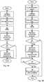
- Figs 4A-Bare flow charts illustrating embodiments of methods for announcing availability of a software container. The method is performed in a server such as one or all of the servers of Fig 1 .
- execution of the software containeris initialised in the server. This can be triggered by the server or from signalling from another node, such as the container allocator.
- a lookup key associated with the software containeris calculated. This step corresponds to step 42 of Figs 3A-B .
- a store step 54an address of the server is stored in association with the lookup key in a distributed peer-to-peer repository. This allows the server to be located based on the lookup key.
- the software containerhas been started but not allocated to a client.
- a connection request to allocate the software container to a clientis received. This can be received from the container allocator.
- a conditional ok step 55the server determines whether to grant the connection request. For instance, each software container can only be allocated once, whereby the connection request is only granted if the software container in question has not been allocated at this time. If the connection request is granted, the method proceeds to a transmit allocation acceptance step 58. Otherwise, the method ends.
- an allocation acceptance messageis transmitted, e.g. to the container allocator. This can be sent to the container allocator. This indicates success of the allocation to the recipient.
- an allocation agentis injected in the software container.
- the allocation agentis a software process configured to perform all following steps of the method.
- the allocated software container(or more specifically the reference to it) is removed from the repository.
- conditional released step 57it is determined whether the software container has been released, i.e. when it is not needed by any client any more. When this is the case, the method proceeds to an optional end execution of SW container step 59. Otherwise, the method re-executes this step, optionally after a delay (not shown).
- SW container step 59the execution of the software container ends. This ends the lifetime of the software container, forming part of the transient container concept.
- Fig 5is a schematic diagram illustrating components of the container allocator 1 of Fig 1 .
- a processor 60is provided using any combination of one or more of a suitable central processing unit (CPU), multiprocessor, microcontroller, digital signal processor (DSP), application specific integrated circuit etc., capable of executing software instructions 67 stored in a memory 65, which can thus be a computer program product.
- the processor 60can be configured to execute the method described with reference to Figs 3A-B above.
- the memory 65can be any combination of read and write memory (RAM) and read only memory (ROM).
- the memory 65also comprises persistent storage, which, for example, can be any single one or combination of magnetic memory, optical memory, solid state memory or even remotely mounted memory.
- a data memory 66is also provided for reading and/or storing data during execution of software instructions in the processor 60.
- the data memory 66can be any combination of read and write memory (RAM) and read only memory (ROM).
- the container allocator 1further comprises an I/O interface 62 for communicating with other external entities.
- the I/O interface 62also includes a user interface.
- Fig 6is a schematic diagram illustrating components of the each one of the servers 4 of Fig 1 , here represented by a single server 4.
- a processor 70is provided using any combination of one or more of a suitable central processing unit (CPU), multiprocessor, microcontroller, digital signal processor (DSP), application specific integrated circuit etc., capable of executing software instructions 77 stored in a memory 75, which can thus be a computer program product.
- the processor 70can be configured to execute the method described with reference to Figs 4A-B above.
- the memory 75can be any combination of read and write memory (RAM) and read only memory (ROM).
- the memory 75also comprises persistent storage, which, for example, can be any single one or combination of magnetic memory, optical memory, solid state memory or even remotely mounted memory.
- a data memory 76is also provided for reading and/or storing data during execution of software instructions in the processor 70.
- the data memory 76can be any combination of read and write memory (RAM) and read only memory (ROM).
- the server 4further comprises an I/O interface 72 for communicating with other external entities.
- the I/O interface 72also includes a user interface.
- Fig 7is a schematic diagram showing functional modules of the container allocator 1 of Fig 5 according to one embodiment.
- the modulesare implemented using software instructions such as a computer program executing in the container allocator 1.
- the modulescorrespond to the steps in the methods illustrated in Figs 3A and 3B .
- a receiver 80corresponds to step 40.
- a calculator 82corresponds to step 42.
- a fallback manager 83corresponds to step 43.
- a repository manager 84corresponds to step 44 and step 48.
- a selector 86corresponds to step 46.
- a connector 87corresponds to step 47 and step 49.
- a success determiner 85corresponds to step 45.
- a counter 81corresponds to step 41.
- Fig 8is a schematic diagram showing functional modules of the server 4 of Fig 6 according to one embodiment.
- the modulesare implemented using software instructions such as a computer program executing in the server 4.
- the modulescorrespond to the steps in the methods illustrated in Figs 4A and 4B .
- An execution manager 92corresponds to step 50, step 51 and step 59.
- a calculator 93corresponds to step 52.
- a repository manager 94corresponds to step store 54.
- a receiver 96corresponds to step 56.
- a transmitter 98corresponds to 58.
- a release determiner 97corresponds to 57.
- Fig 9shows one example of a computer program product comprising computer readable means.
- a computer program 91can be stored, which computer program can cause a processor to execute a method according to embodiments described herein.
- the computer program productis an optical disc, such as a CD (compact disc) or a DVD (digital versatile disc) or a Blu-Ray disc.
- the computer program productcould also be embodied in a memory of a device, such as the computer program product 67 of Fig 5 or 77 of Fig 6 .
- While the computer program 91is here schematically shown as a track on the depicted optical disk, the computer program can be stored in any way which is suitable for the computer program product, such as a removable solid state memory, e.g. a Universal Serial Bus (USB) drive.
- a removable solid state memorye.g. a Universal Serial Bus (USB) drive.
- USBUniversal Serial Bus
Landscapes
- Engineering & Computer Science (AREA)
- Software Systems (AREA)
- Theoretical Computer Science (AREA)
- Physics & Mathematics (AREA)
- General Engineering & Computer Science (AREA)
- General Physics & Mathematics (AREA)
- Computer Networks & Wireless Communication (AREA)
- Signal Processing (AREA)
- Information Transfer Between Computers (AREA)
- Computer And Data Communications (AREA)
Description
- The invention relates to methods, a container allocator, a server, computer programs and computer program products for allocating a software container or announcing availability of a software container.
- Recently, microservices have become a popular architecture to build modern Web services. By breaking down a complex monolithic application into small independent services it becomes possible to develop services that are more resilient to error and more scalable. For example, if a particular microservice would fail, it would not affect the entire service. However, if a component part of a monolithic service would fail, the entire service would have to be restarted. Also, the only way to scale a monolithic service is to duplicate the whole monolith by adding more instances of it. In a microservice based architecture on the other hand, only the services that need to be scaled need to be duplicated.
- Software containers are commonly used to implement microservice-based architectures and make sure services can run independently of each other. In contrast to virtual machines, software containers are more lightweight and can instantly be started, similar to standard Unix processes, assuming the server has all images required to start the container. Another advantage is that software containers provide a reliable execution environment allowing developers to develop and test their services locally on their machine and then upload the image to a cloud platform and still be sure the containers behave similarly as running them locally.
- Docker is an example of a container runtime that has recently gained popularity. By allowing container images to be stacked in a so-called union file system, container images can more efficiently be distributed.
- However, when adopting a microservice based container architecture, designers and developers still need to figure out how to manage the life cycle of individual components, for example when to start a new service, when to scale it, how to handle fault recovery and so on.
- Additionally, a general problem with current container based architectures is that it takes time to start new containers. This is particularly a problem when using cluster management platforms such as Apache Mesos where the start-up delay can vary from a couple of seconds up to several minutes depending if the selected server in the cluster already has the necessary container images required to start the container in local storage or not. Without taking precautionary actions, a fresh new server added to the cluster has typically no container images at all, and will thus cause a significant delay. Also, finding a suitable server in the cluster for running the container as well as starting it up adds to the delay.
- From a user perspective, the service should start without noticeable delay or at least with acceptable delay. To give a perspective, a common practice is to minimize the size of JavaScript code loaded by Web browser to more quickly start a Web application. Waiting several minutes for deploying a container would in many cases not be a practical solution. Consequently, adopting a design principle where containers are started on demand would not be possible in such a case.
- The article entitled "Peer-to-Peer Cloud Provisioning: Service Discovery and Load-Balancing" by Ranjan ET AL discloses a distributed peer-to-peer cloud provisioning system using distributed hash tables.
- It is an object to enable lower start-up times for software containers. According to a first aspect, it is provided a method for allocating a software container executing on a server of a set of servers. The method is performed in a container allocator and comprising the steps of: receiving a request to invoke a software container for a client; calculating a lookup key associated with the software container; performing a lookup in a distributed peer-to-peer repository using the lookup key, giving a result set of active software containers; selecting one software container from the set of software containers; and connecting to the selected software container to allocate the selected software container to the client.
- According to a second aspect, it is provided a container allocator configured to allocate a software container executing on a server of a set of servers. The container allocator comprises: a processor; and a memory storing instructions that, when executed by the processor, cause the container allocator to: receive a request to invoke a software container for a client; calculate a lookup key associated with the software container; perform a lookup in a distributed peer-to-peer repository using the lookup key, giving a result set of active software containers; select one software container from the set of software containers; and connect to the selected software container to allocate the selected software container to the client.
- According to a third aspect, it is provided a container allocator comprising: means for receiving a request to invoke a software container for a client; means for calculating a lookup key associated with the software container; means for performing a lookup in a distributed peer-to-peer repository using the lookup key, giving a result set of active software containers executing on respective servers of a set of servers; means for selecting one software container from the set of software containers; and means for connecting to the selected software container to allocate the selected software container to the client.
- According to a fourth aspect, it is provided a computer program for allocating a software container executing on a server of a set of servers. The computer program comprises computer program code which, when run on a container allocator cause the container allocator to: receive a request to invoke a software container for a client; calculate a lookup key associated with the software container; perform a lookup in a distributed peer-to-peer repository using the lookup key, giving a result set of active software containers; select one software container from the set of software containers; and connect to the selected software container to allocate the selected software container to the client.
- According to a fifth aspect, it is provided a computer program product comprising a computer program according to the fourth aspect and a computer readable means on which the computer program is stored.
- According to a sixth aspect, it is provided a method for announcing availability of a software container. The method is performed in a server, and comprises the steps of: initialising execution of the software container in the server; calculating a lookup key associated with the software container; storing an address of the server in association with the lookup key in a distributed peer-to-peer repository; receiving a connection request to allocate the software container to a client; and transmitting an allocation acceptance message.
- According to a seventh aspect, it is provided a server configured to announce availability of a software container. The server comprises: a processor; and a memory storing instructions that, when executed by the processor, cause the server to: initialise execution of the software container in the server; calculate a lookup key associated with the software container; store an address of the server in association with the lookup key in a distributed peer-to-peer repository; receive a connection request to allocate the software container to a client; and transmit an allocation acceptance message.
- According to an eighth aspect, it is provided a server comprising: means for initialising execution of a software container in the server; means for calculating a lookup key associated with the software container; means for storing an address of the server in association with the lookup key in a distributed peer-to-peer repository; means for receiving a connection request to allocate the software container to a client; and means for transmitting an allocation acceptance message.
- According to a ninth aspect, it is provided a computer program for announcing availability of a software container, the computer program comprises computer program code which, when run on a server cause the server to: initialise execution of the software container in the server; calculate a lookup key associated with the software container; store an address of the server in association with the lookup key in a distributed peer-to-peer repository; receive a connection request to allocate the software container to a client; and transmit an allocation acceptance message.
- According to a tenth aspect, it is provided a computer program product comprising a computer program according to the ninth aspect and a computer readable means on which the computer program is stored.
- Generally, all terms used in the claims are to be interpreted according to their ordinary meaning in the technical field, unless explicitly defined otherwise herein. All references to "a/an/the element, apparatus, component, means, step, etc." are to be interpreted openly as referring to at least one instance of the element, apparatus, component, means, step, etc., unless explicitly stated otherwise. The steps of any method disclosed herein do not have to be performed in the exact order disclosed, unless explicitly stated.
- The invention is now described, by way of example, with reference to the accompanying drawings, in which:
Fig 1 is a schematic drawing illustrating an environment in which embodiments presented herein can be applied;Fig 2 is a schematic drawing illustrating a server shown inFig 1 ;Figs 3A-B are flow charts illustrating embodiments of methods for allocating a software container;Figs 4A-B are flow charts illustrating embodiments of methods for announcing availability of a software container;Fig 5 is a schematic diagram illustrating components of the container allocator ofFig 1 ;Fig 6 is a schematic diagram illustrating components of the servers ofFig 1 ;Fig 7 is a schematic diagram showing functional modules of the container allocator ofFig 5 according to one embodiment;Fig 8 is a schematic diagram showing functional modules of the server ofFig 6 according to one embodiment; andFig 9 shows one example of a computer program product comprising computer readable means.- The invention will now be described more fully hereinafter with reference to the accompanying drawings, in which certain embodiments of the invention are shown. This invention may, however, be embodied in many different forms and should not be construed as limited to the embodiments set forth herein; rather, these embodiments are provided by way of example so that this disclosure will be thorough and complete, and will fully convey the scope of the invention to those skilled in the art. Like numbers refer to like elements throughout the description.
Fig 1 is a schematic drawing illustrating an environment in which embodiments presented herein can be applied.- There are here a number of
servers 4a-e forming part of aset 8 of servers. While there are fiveservers 4a-e shown here, theset 8 of servers can contain any suitable number of servers. Each one of theservers 4a-e can execute software containers when required, as described in more detail below. - For instance, the software containers can be containers running on a Docker platform. The software containers are distributed as images being files (images are here not to be confused with illustrations/photographs). Moreover, a method called process injection is used to transparently add additional processes into the container and then modify the boot order. This makes it possible to inject management processes into the containers, for example service composition processes allowing containers to self-configure. Here, process injection can be used to inject a process for an allocation agent in the software container. The allocation agent communicates with a
container allocator 1 to assist in the allocation of software containers to one ormore clients 5. Eachclient 5 here at some point wants to make use of a software container. It is to be noted that each client can also be a server for another context; it is only in relation to a software container described here that theclient 5 is a client. - A
deployment tool 7 is used when new software containers are to be deployed. Thedeployment tool 7 communicates with thecontainer allocator 1 for the deployment. - The set of
servers 8 is organised in a decentralized peer-to-peer network, which can be implemented on an underlying network, such as an IP (Internet Protocol) network. Some of the software containers in the network are active but not allocated to any clients. The active but not allocated containers can be discovered by clients using thecontainer allocator 1 such that once they have been discovered it is ensured that the software container is not allocated multiple times by other clients. Since the containers are already active, i.e. executing, the start up time when a client requests a software container is minimal. This mechanism makes it possible to implement transient containers, which are containers allocated on demand to clients and only exist for a limited amount time. - Once the
client 5 releases communication with the server, the execution of the software container ends. Each software container is here an instance of a software image. Using the peer-to-peer network, the presented embodiment is decentralized; meaning that there is no directory service or central controller that is responsible for allocation. Every server in the network is equal, and it is the network itself, which provides the proposed discovery mechanism to allocate containers. Hence, there may beseveral container allocators 1 executing in parallel for the same set ofservers 8. - To provide the decentralized solution, the proposed discovery algorithm can be based on a Distributed Hash Table (DHT) algorithm, such as Kademlia, Chord or Pastry.
- The allocation agent which is injected at deployment connects to the peer-to-
peer network 8 and publishes a checksum (e.g. SHA (Secure Hash Algorithm)-i) of a blueprint for the software container and information how to connect to the allocation agent. The blueprint contains information such or metadata of the image, e.g.: {"container": {"image":
"docker:///sampledockerregistry.foo.com:443/videoconf"}}, here containing container image(s) URL, etc. needed to start the container. The blueprint may optionally contain additional metadata, such as version numbers or memory or CPU constraints. The blueprint may also be a reference, a checksum (such as Secure Hash Algorithm 1 (SHA-1)) or a other identifier (e.g. UUID) as long as the underlying system can resolve the identifier and retrieve information on how to deploy the containers. - When a
client 5 needs the services of a software container executing a particular functionality (provisioned by the software image), the container allocator calculates the checksum (being a lookup key) of a blueprint of the requested image and performs a lookup of the checksum in the peer-to-peer repository implemented e.g. by the DHT. In this way, the container allocator discovers the allocation agents of the software containers matching the specified blueprint. The container allocator 3 then randomly selects an allocation agent and tries to connect to it. An allocation agent will only accept one single connection during its lifetime, and a container is successfully allocated to aparticular client 5 if the Container Allocator managed to connect to the selected Allocation Agent. - Different instances of the same software container can execute in parallel on different servers to thereby achieve transient containers. In
Fig 1 , afirst software container 2a is a pre-started instance of a particular image executing on afirst server 4a. In parallel, asecond software container 2b is a pre-started instance executing on asecond server 4b. Thesecond software container 2b is an instance of the same image which is used for thefirst software container 2a. Hence, their blueprints are the same and their checksums are the same. - This structure allows the use of transient containers, where software containers are allocated on demand, for example triggered by an external event such as a user loads a particular web page (URL).
- The
client 5 can be any suitable type of client. One non-limiting example is that theclient 5 could be a client for a communication session, e.g. in accordance with Matrix.org which is an open standard for a protocol that can be used to set up communication sessions, where each session corresponds to an online virtual room. When users enter a virtual room (e.g. by opening a URL in a web browser) they will join the meeting or conference to meet other participants connected to the same room. - An interesting characteristic of an online virtual room is that resources connected to room (e.g. a video conferencing service or a data synchronization service) only needs to be allocated as long as there are participating users. Using the structure provided here, all needed resources can be allocated on demand, for example by starting all needed containers when the first user join the room, and then stop all containers when all users have left. The concept of transient containers could therefore be an efficient design principle for implementing online video conferencing services.
- Using the embodiment of
Fig 1 , it is possible to more or less instantly start containers, and it is thus possible to use transient containers as a design pattern to more efficiently implement new Internet services and applications. - As a container is created on demand when needed and only exists for a limited time, it is very easy to scale a service by adding more hardware, for example adding more servers to the set of servers 8 (peer-to-peer network). This architecture supports great scalability and can support massive amounts of servers.
- If a transient container crashes, it will not affect the entire service, but only the clients connected to the container that crashed are affected. Also, as the containers are never reused, a client will always connect to a fresh instance. This eliminates effects of software bugs such as memory leaks that could otherwise drain computational resources over time.
- As transient containers are shutdown after being used, all states stored in the container are lost, making it harder to hack the system to retrieve historical data.
- It becomes possible to introduce a new version of particular container without affecting previously running sessions, e.g. a videoconference session. The videoconference session will eventually be upgraded once all users have left the conference and then join the same conference room at a later occasion. Also, all new conference sessions will immediately start using the new containers images once they have been introduced. Again, this will not affect already running sessions.
Fig 2 is a schematic drawing illustrating aserver 4 shown inFig 1 . Theserver 4 can be any of theservers 4a-e shown inFig 1 .- The
server 4 comprises one ormore software containers 2. Each software container is an instance of an image and contains, apart from its operative software, anallocation agent 11, injected at deployment and a peer-to-peer repository 10. The peer-to-peer repository is implemented e.g. using DHT as described above. - Each software container can be active and not allocated, active and allocated or not running. Each
software container 2 can be allocated to only one session (or client) and after the client releases the software container, the execution of thesoftware container 2 ends and is not started again. However, the server can start anew software container 2 being an instance of the same or a different image. - Now an embodiment of the peer-to-peer network for the servers will be described based on Bitverse. Bitverse is a framework to build decentralized peer-to-peer application. Bitverse is based on the Kademlia DHT algorithm and provides a messaging API (Application Programming Interface) and a key value store API. In both APIs, self-generated SHA-1 strings are used to identify node end-points and data objects. Bitverse is thus a DHT implementation of a decentralised repository.
- Bitverse consists of two different types of nodes, super nodes and edge nodes. Edge nodes are connected using web sockets to a super node and thus forms a star topology. An edge node can either run as a library in a web browser client or in a server component directly.
- Super nodes communicate using UDP (User Datagram Protocol). Messages are routed using a routing table provides by Kademlia. The routing table consists of 160 buckets where each bucket contains a limited list of contacts (typically 20) discovered by the super node. XOR (Exclusive OR) is used to determine the distance between two different nodes in the network and which bucket a contact should be stored in. This makes it possible to implement an iterative protocol where a node calculates which contacts in its routing table that has the shortest distance to a particular string, or the SHA-1 of the string to be more specific. These contact are then queries until there are no more nodes to query. This makes it possible to find the nodes in the whole network that has the shortest distance to a particular string. Like all DHTs, this procedure is very efficient, typicallyO(log n) messages need to be sent, where is n is the number of nodes in the network and O denotes order.
- By calculating a SHA-1 of the key it becomes possible to calculate which nodes in the network a particular key-value pair should be stored, and thus implement a distributed data repository where data is replicated in the network. In Bitverse, the value is represented as an unordered set, which makes it possible to store multiple values associated with a specific key. This special key-value(s) pair is called a SetMap. Below is an example of SetMap storing 5 values, identified by the key "hello".
- The SetMap provides a simple API, for example
- The SetMap API can be used by the allocation agents to store registration data for a software container. The SetMap is also used internally in Bitverse to provide a messaging service. When an edge node connects to a super node, the super node will store IP number and UDP port of the super node as a value in a SetMap, where the self-generated SHA-1 id of the edge node is used as a key. This makes it possible for an edge node to send messages to any other edge node in the network, by allow the super nodes to use the information stored in the SetMap to set up tunnels between different super nodes.
- Below is an example of a messaing API call to send a message to an edge node, where4cd7e1804bad563d32a416df5f915efbb013ee6f is the address of the receiving edge node.
- The message will then be sent to the connected super node, which will if necessary tunnel the message to a foreign super node where the receiving edge node is connected.
- As used herein, the lookup key can be the checksum of the blueprint of a software container and the values are the Bitverse edge node addresses to the injected allocation agents executing on servers. Note that it would also be possible to use regular TCP or UDP to communicate with the allocation agents. Also, to authenticate the container allocator, in one embodiment, the container allocator uploads a public key to the allocation agents and signs outgoing messages from the container allocator.
Figs 3A-B are flow charts illustrating embodiments of methods for allocating a software container. The method is performed in a container allocator. First the method illustrated byFig 4A will be described.- In areceive
request step 40, a request to invoke a software container for a client is received. The request can be received from the client. - In acalculate lookup
key step 42, a lookup key associated with of the software container is calculated. The lookup key can e.g. be a checksum of a blueprint for the software container as described above. The blueprint can include or consist of metadata for the software container. - In a
perform lookup step 44, a lookup is performed in a distributed peer-to-peer repository using the lookup key. This gives a result set of active software containers. The set can contain zero, one or more active software containers, or more accurately references to the zero, one or more active software containers. The distributed repository may be based on a distributed hash table. - When SetMap is used as described above, the perform lookup can be performed like the following example:
- allocationSet =
bitverse.getSetMap("4520fbc78612aeb22f53f156a4a259295216fcfa") - where the string between the quotes is the lookup key. In our example, this can give the result of two Bitverse edge node addresses:
- c724188d998c768c5ddda85oac3o64a3fc623864, and
- c8ea48d7168cb1o7a161d7f5bd7277ao2344bb82.
- In aselect
SW container step 46, one software container (or its allocation agent) is selected from the set of software containers. The choice can e.g. be a random (or pseudo-random) selection from the set of software containers. For instance, the software container with addressc8ea48d7168cb107a161d7f5bd7277a02344bb82 could be selected in our example. - In a
connect step 47, the container allocator connects to the selected software container to allocate the selected software container to the client. For example, the container allocator can connect to an allocation agent having been injected in the software container. - At this point, the client and the software container can communicate and use each other's functionality. Optionally, the client connects through the container allocator and does not know the exact location or IP (Internet Protocol) address of the server running the software container.
- Looking now to
Fig 3B , only new or modified steps compared to the method illustrated by the flow chart ofFig 3A will be described. - In an optionalstart fallback
SW container step 43, a fallback software container is started in a server of the set of servers. Optionally, several fallback software containers can be started in one or more of the servers. - In an optional
conditionalsuccess step 45, it is determined when the software container is successfully allocated to the client. If this is the case, the method proceeds to aremoveSW container step 48. Otherwise, the method proceeds to an optional conditionalmaxnbr step 41, or when that step is not performed, to an optionalconnect to fallbackSW container step 49. The determination of success is particularly useful when there are several container allocators using the same peer-to-peer network, in which another container allocator could allocate the selected software container between the selection instep 46 and a confirmed connection instep 47. The success can be based on signalling received from the server based on theconnect step 47. - In the optional conditional
maxnbr step 41, it is determined whether a maximum number of attempts of connecting have been performed. If this is the case, the method proceeds to theconnect to fallbackSW container step 49. Otherwise, the method returns to theselectSW container step 46 to select a new SW container to attempt to connect to. In other words, a software container is determined to fail to be allocated to the client when none of the instances of connecting to the selected software container results in a successful allocation to the client. - In an optionalremove
SW container step 48, the allocated software container is removed from the repository. This prevents any other client from being allocated the software container which has just successfully been allocated to the client. It is only possible to connect once to a software container. - In an optionalconnect to fallback
SW container step 49, the container allocator connects to the fallback software container to allocate the fallback software container to the client. This was started instep 43 and has had some time to initialise, whereby any delay experienced by the client is reduced compared to starting a software container at this point. - Optionally, a separate process checks if the number of containers in the distributed peer-to-peer repository is below a certain threshold and then pre-start new containers if that is the case. It would also be possible to develop a decentralized algorithm executed by each container to self-replicate the containers to make sure there are enough instances in the repository.
- After this method is performed, the client can connect to the software container. One embodiment could be that the container allocator receives connection information when connecting to a software container how to further connect to a process (such as a Unix process) running inside the container. Another embodiment could be to develop a rendezvous protocol, for example using a Bitverse SetMap to discover the allocated container.
Figs 4A-B are flow charts illustrating embodiments of methods for announcing availability of a software container. The method is performed in a server such as one or all of the servers ofFig 1 .- In an
initialise execution step 51, execution of the software container is initialised in the server. This can be triggered by the server or from signalling from another node, such as the container allocator. - In acalculate lookup
key step 52, a lookup key associated with the software container is calculated. This step corresponds to step 42 ofFigs 3A-B . - In a
store step 54, an address of the server is stored in association with the lookup key in a distributed peer-to-peer repository. This allows the server to be located based on the lookup key. At this stage, the software container has been started but not allocated to a client. - In areceive
connection request step 56, a connection request to allocate the software container to a client is received. This can be received from the container allocator. - In a conditional
ok step 55, the server determines whether to grant the connection request. For instance, each software container can only be allocated once, whereby the connection request is only granted if the software container in question has not been allocated at this time. If the connection request is granted, the method proceeds to atransmitallocation acceptance step 58. Otherwise, the method ends. - In thetransmit
allocation acceptance step 58, an allocation acceptance message is transmitted, e.g. to the container allocator. This can be sent to the container allocator. This indicates success of the allocation to the recipient. - Looking now to
Fig 4B , only new or modified steps compared to the method illustrated by the flow chart ofFig 4A will be described. - In an optionalinject
allocation agent step 50, an allocation agent is injected in the software container. The allocation agent is a software process configured to perform all following steps of the method. - In an optionalremove
SW container step 55, the allocated software container (or more specifically the reference to it) is removed from the repository. - In an optional conditionalreleased
step 57, it is determined whether the software container has been released, i.e. when it is not needed by any client any more. When this is the case, the method proceeds to an optionalend execution ofSW container step 59. Otherwise, the method re-executes this step, optionally after a delay (not shown). - In the optionalend execution of
SW container step 59, the execution of the software container ends. This ends the lifetime of the software container, forming part of the transient container concept. Fig 5 is a schematic diagram illustrating components of thecontainer allocator 1 ofFig 1 . Aprocessor 60 is provided using any combination of one or more of a suitable central processing unit (CPU), multiprocessor, microcontroller, digital signal processor (DSP), application specific integrated circuit etc., capable of executingsoftware instructions 67 stored in amemory 65, which can thus be a computer program product. Theprocessor 60 can be configured to execute the method described with reference toFigs 3A-B above.- The
memory 65 can be any combination of read and write memory (RAM) and read only memory (ROM). Thememory 65 also comprises persistent storage, which, for example, can be any single one or combination of magnetic memory, optical memory, solid state memory or even remotely mounted memory. - A
data memory 66 is also provided for reading and/or storing data during execution of software instructions in theprocessor 60. Thedata memory 66 can be any combination of read and write memory (RAM) and read only memory (ROM). - The
container allocator 1 further comprises an I/O interface 62 for communicating with other external entities. Optionally, the I/O interface 62 also includes a user interface. - Other components of the
container allocator 1 are omitted in order not to obscure the concepts presented herein. Fig 6 is a schematic diagram illustrating components of the each one of theservers 4 ofFig 1 , here represented by asingle server 4. Aprocessor 70 is provided using any combination of one or more of a suitable central processing unit (CPU), multiprocessor, microcontroller, digital signal processor (DSP), application specific integrated circuit etc., capable of executingsoftware instructions 77 stored in amemory 75, which can thus be a computer program product. Theprocessor 70 can be configured to execute the method described with reference toFigs 4A-B above.- The
memory 75 can be any combination of read and write memory (RAM) and read only memory (ROM). Thememory 75 also comprises persistent storage, which, for example, can be any single one or combination of magnetic memory, optical memory, solid state memory or even remotely mounted memory. - A
data memory 76 is also provided for reading and/or storing data during execution of software instructions in theprocessor 70. Thedata memory 76 can be any combination of read and write memory (RAM) and read only memory (ROM). - The
server 4 further comprises an I/O interface 72 for communicating with other external entities. Optionally, the I/O interface 72 also includes a user interface. - Other components of the
server 4 are omitted in order not to obscure the concepts presented herein. Fig 7 is a schematic diagram showing functional modules of thecontainer allocator 1 ofFig 5 according to one embodiment. The modules are implemented using software instructions such as a computer program executing in thecontainer allocator 1. The modules correspond to the steps in the methods illustrated inFigs 3A and 3B .- A
receiver 80 corresponds to step 40. - A
calculator 82 corresponds to step 42. - A
fallback manager 83 corresponds to step 43. - A
repository manager 84 corresponds to step 44 andstep 48. - A
selector 86 corresponds to step 46. - A
connector 87 corresponds to step 47 andstep 49. - A
success determiner 85 corresponds to step 45. - A
counter 81 corresponds to step 41. Fig 8 is a schematic diagram showing functional modules of theserver 4 ofFig 6 according to one embodiment. The modules are implemented using software instructions such as a computer program executing in theserver 4. The modules correspond to the steps in the methods illustrated inFigs 4A and 4B .- An
execution manager 92 corresponds to step 50,step 51 andstep 59. - A
calculator 93 corresponds to step 52. - A
repository manager 94 corresponds to stepstore 54. - A
receiver 96 corresponds to step 56. - A
transmitter 98 corresponds to 58. - A
release determiner 97 corresponds to 57. Fig 9 shows one example of a computer program product comprising computer readable means. On this computer readable means acomputer program 91 can be stored, which computer program can cause a processor to execute a method according to embodiments described herein. In this example, the computer program product is an optical disc, such as a CD (compact disc) or a DVD (digital versatile disc) or a Blu-Ray disc. As explained above, the computer program product could also be embodied in a memory of a device, such as thecomputer program product 67 ofFig 5 or 77 ofFig 6 . While thecomputer program 91 is here schematically shown as a track on the depicted optical disk, the computer program can be stored in any way which is suitable for the computer program product, such as a removable solid state memory, e.g. a Universal Serial Bus (USB) drive.- The invention has mainly been described above with reference to a few embodiments. However, as is readily appreciated by a person skilled in the art, other embodiments than the ones disclosed above are equally possible within the scope of the invention, as defined by the appended patent claims.
Claims (9)
- A method for allocating a software container (2) executing on a server (4) of a set of servers, the method being performed in a container allocator (1) and comprising the steps of:receiving (40) a request to invoke a software container for a client (5);calculating (42) a lookup key associated with the software container (2);starting (43) a fallback software container in a server (4) of the set of servers;performing (44) a lookup in a distributed peer-to-peer repository (10) using the lookup key, giving a result set (20) of active software containers (2);selecting (46) one software container (2) from the set of software containers (2);connecting (47) to the selected software container to allocate the selected software container to the client (5); andwhen the software container fails to be allocated to the client (5), connecting (49) to the fallback software container to allocate the fallback software container to the client (5).
- The method according to claim 1, further comprising the step of:
when the software container is successfully allocated to the client (5), removing (48) the allocated software container from the repository (10). - The method according to any one of the preceding claims, wherein the distributed repository is based on a distributed hash table.
- The method according to claim 1, wherein the step of selecting (46) and connecting (47) are repeated a predetermined number times and wherein the software container is determined to fail to be allocated to the client (5) when none of the instances of connecting to the selected software container results in a successful allocation to the client (5).
- A container allocator (1) configured to allocate a software container (2) executing on a server (4) of a set of servers, the container allocator comprising:a processor (60); anda memory (64) storing instructions (66) that, when executed by the processor, cause the container allocator (1) to:receive a request to invoke a software container for a client (5);calculate a lookup key associated with the software container (2);start a fallback software container in a server (4) of the set of servers;perform a lookup in a distributed peer-to-peer repository (10) using the lookup key, giving a result set (20) of active software containers (2);select one software container (2) from the set of software containers (2);connect to the selected software container to allocate the selected software container to the client (5); andwhen the software container fails to be allocated to the client (5), connect to the fallback software container to allocate the fallback software container to the client (5).
- The container allocator (1) according to claim 5, further comprising instructions (66) that, when executed by the processor, cause the container allocator (1) to: when the software container is successfully allocated to the client (5), removing the allocated software container from the repository (10).
- The container allocator (1) according to claim 5 or 6, wherein the distributed repository is based on a distributed hash table.
- The container allocator (1) according to claim 5, further comprising instructions (66) that, when executed by the processor, cause the container allocator (1) to repeat the instructions to select and connect a predetermined number times and to determine the software container to have failed to be allocated to the client (5) when none of the instances of connecting to the selected software container results in a successful allocation to the client (5).
- A computer program (91) for allocating a software container (2) executing on a server (4) of a set of servers, the computer program comprising computer program code which, when run on a container allocator (1) cause the container allocator (1) to:receive a request to invoke a software container for a client (5);calculate a lookup key associated with the software container (2);start a fallback software container in a server (4) of the set of servers;perform a lookup in a distributed peer-to-peer repository (10) using the lookup key, giving a result set (20) of active software containers (2);select one software container (2) from the set of software containers (2);connect to the selected software container to allocate the selected software container to the client (5); andwhen the software container fails to be allocated to the client (5), connect to the fallback software container to allocate the fallback software container to the client (5).
Applications Claiming Priority (2)
| Application Number | Priority Date | Filing Date | Title |
|---|---|---|---|
| US201562170264P | 2015-06-03 | 2015-06-03 | |
| PCT/SE2015/050749WO2016195562A1 (en) | 2015-06-03 | 2015-06-26 | Allocating or announcing availability of a software container |
Publications (2)
| Publication Number | Publication Date |
|---|---|
| EP3304303A1 EP3304303A1 (en) | 2018-04-11 |
| EP3304303B1true EP3304303B1 (en) | 2021-06-09 |
Family
ID=53502818
Family Applications (1)
| Application Number | Title | Priority Date | Filing Date |
|---|---|---|---|
| EP15733943.3AActiveEP3304303B1 (en) | 2015-06-03 | 2015-06-26 | Allocating or announcing availability of a software container |
Country Status (3)
| Country | Link |
|---|---|
| US (1) | US10528379B2 (en) |
| EP (1) | EP3304303B1 (en) |
| WO (1) | WO2016195562A1 (en) |
Families Citing this family (27)
| Publication number | Priority date | Publication date | Assignee | Title |
|---|---|---|---|---|
| CN106445473B (en)* | 2015-08-06 | 2019-12-06 | 华为技术有限公司 | container deployment method and device |
| US11283900B2 (en) | 2016-02-08 | 2022-03-22 | Microstrategy Incorporated | Enterprise performance and capacity testing |
| US10440153B1 (en) | 2016-02-08 | 2019-10-08 | Microstrategy Incorporated | Enterprise health score and data migration |
| US10417065B2 (en) | 2016-06-13 | 2019-09-17 | Dynatrace Llc | Method and system for automated agent injection in container environments |
| US10761881B2 (en)* | 2016-06-28 | 2020-09-01 | Telefonaktiebolaget Lm Ericsson (Publ) | Managing a lifecycle of a software container |
| CN106533804A (en)* | 2016-12-22 | 2017-03-22 | 成都西加云杉科技有限公司 | Network operation support system |
| WO2018141363A1 (en)* | 2017-01-31 | 2018-08-09 | Telefonaktiebolaget Lm Ericsson (Publ) | Security for a software container |
| CN106933635B (en)* | 2017-03-15 | 2020-06-30 | 北京搜狐新媒体信息技术有限公司 | Docker mirror image generation method and Docker container |
| US10956563B2 (en)* | 2017-11-22 | 2021-03-23 | Aqua Security Software, Ltd. | System for securing software containers with embedded agent |
| US10997283B2 (en)* | 2018-01-08 | 2021-05-04 | Aqua Security Software, Ltd. | System for securing software containers with encryption and embedded agent |
| US11625360B2 (en) | 2018-06-20 | 2023-04-11 | Kyndryl, Inc. | Tailoring container images to a specific microarchitecture in virtualized environments |
| US11321130B2 (en)* | 2019-08-01 | 2022-05-03 | Kyndryl, Inc. | Container orchestration in decentralized network computing environments |
| US11829742B2 (en) | 2019-08-15 | 2023-11-28 | Microstrategy Incorporated | Container-based server environments |
| US11106455B2 (en) | 2019-08-15 | 2021-08-31 | Microstrategy Incorporated | Integration of containers with external elements |
| US11288053B2 (en) | 2019-08-15 | 2022-03-29 | Microstrategy Incorporated | Conversion and restoration of computer environments to container-based implementations |
| US11637748B2 (en) | 2019-08-28 | 2023-04-25 | Microstrategy Incorporated | Self-optimization of computing environments |
| US11507295B2 (en) | 2019-08-30 | 2022-11-22 | Microstrategy Incorporated | Backup, restoration, and migration of computer systems |
| US11210189B2 (en) | 2019-08-30 | 2021-12-28 | Microstrategy Incorporated | Monitoring performance of computing systems |
| US11354216B2 (en) | 2019-09-18 | 2022-06-07 | Microstrategy Incorporated | Monitoring performance deviations |
| US11360881B2 (en) | 2019-09-23 | 2022-06-14 | Microstrategy Incorporated | Customizing computer performance tests |
| US11438231B2 (en) | 2019-09-25 | 2022-09-06 | Microstrategy Incorporated | Centralized platform management for computing environments |
| US11836158B2 (en) | 2020-02-03 | 2023-12-05 | Microstrategy Incorporated | Deployment of container-based computer environments |
| US11892939B2 (en) | 2020-03-21 | 2024-02-06 | Dynatrace Llc | Automatic injection of agents into processes executing statically linked binaries |
| US11995350B2 (en)* | 2020-12-23 | 2024-05-28 | Red Hat, Inc. | Prefetching container data in a data storage system |
| US11954473B2 (en) | 2021-09-20 | 2024-04-09 | Microstrategy Incorporated | Deployment architecture for multi-tenant cloud computing systems |
| US11963215B2 (en) | 2021-10-27 | 2024-04-16 | Hewlett Packard Enterprise Development Lp | Resource unit assignment for selective fading |
| US11861342B2 (en) | 2022-01-28 | 2024-01-02 | Microstrategy Incorporated | Enhanced cloud-computing environment deployment |
Citations (1)
| Publication number | Priority date | Publication date | Assignee | Title |
|---|---|---|---|---|
| US20120151477A1 (en)* | 2010-12-14 | 2012-06-14 | Microsoft Corporation | Template virtual machines |
Family Cites Families (13)
| Publication number | Priority date | Publication date | Assignee | Title |
|---|---|---|---|---|
| US6104717A (en)* | 1995-11-03 | 2000-08-15 | Cisco Technology, Inc. | System and method for providing backup machines for implementing multiple IP addresses on multiple ports |
| US7822860B2 (en)* | 2001-12-11 | 2010-10-26 | International Business Machines Corporation | Method and apparatus for dynamic reconfiguration of web services infrastructure |
| US7418454B2 (en)* | 2004-04-16 | 2008-08-26 | Microsoft Corporation | Data overlay, self-organized metadata overlay, and application level multicasting |
| US8176486B2 (en) | 2007-02-15 | 2012-05-08 | Clearcube Technology, Inc. | Maintaining a pool of free virtual machines on a server computer |
| US20100083251A1 (en)* | 2008-09-12 | 2010-04-01 | Hyper9, Inc. | Techniques For Identifying And Comparing Virtual Machines In A Virtual Machine System |
| US20120179778A1 (en) | 2010-01-22 | 2012-07-12 | Brutesoft, Inc. | Applying networking protocols to image file management |
| US9262145B2 (en)* | 2011-10-31 | 2016-02-16 | Hewlett Packard Enterprise Development Lp | Remote software deployment across a network |
| US8904008B2 (en) | 2012-01-09 | 2014-12-02 | Microsoft Corporation | Assignment of resources in virtual machine pools |
| US20140280433A1 (en) | 2013-03-14 | 2014-09-18 | Rackspace Us, Inc. | Peer-to-Peer File Distribution for Cloud Environments |
| MY184239A (en)* | 2013-04-16 | 2021-03-29 | Mimos Berhad | A system and method of fault tolerance for distributed applications in a virtualized environment |
| US9600312B2 (en)* | 2014-09-30 | 2017-03-21 | Amazon Technologies, Inc. | Threading as a service |
| US10833940B2 (en)* | 2015-03-09 | 2020-11-10 | Vapor IO Inc. | Autonomous distributed workload and infrastructure scheduling |
| US10761881B2 (en)* | 2016-06-28 | 2020-09-01 | Telefonaktiebolaget Lm Ericsson (Publ) | Managing a lifecycle of a software container |
- 2015
- 2015-06-26EPEP15733943.3Apatent/EP3304303B1/enactiveActive
- 2015-06-26WOPCT/SE2015/050749patent/WO2016195562A1/ennot_activeCeased
- 2015-06-26USUS15/575,424patent/US10528379B2/enactiveActive
Patent Citations (1)
| Publication number | Priority date | Publication date | Assignee | Title |
|---|---|---|---|---|
| US20120151477A1 (en)* | 2010-12-14 | 2012-06-14 | Microsoft Corporation | Template virtual machines |
Non-Patent Citations (2)
| Title |
|---|
| MARK F MERGEN ET AL: "Virtualization for high-performance computing", OPERATING SYSTEMS REVIEW, ACM, NEW YORK, NY, US, vol. 40, no. 2, 1 April 2006 (2006-04-01), pages 8 - 11, XP058211111, ISSN: 0163-5980, DOI: 10.1145/1131322.1131328* |
| MONIRUZZAMAN A B M ET AL: "Virtual Memory Streaming Technique for virtual machines (VMs) for rapid scaling and high performance in cloud environment", 2014 INTERNATIONAL CONFERENCE ON INFORMATICS, ELECTRONICS & VISION (ICIEV), IEEE, 23 May 2014 (2014-05-23), pages 1 - 6, XP032616217, ISBN: 978-1-4799-5179-6, [retrieved on 20140708], DOI: 10.1109/ICIEV.2014.6850734* |
Also Published As
| Publication number | Publication date |
|---|---|
| US20180157516A1 (en) | 2018-06-07 |
| EP3304303A1 (en) | 2018-04-11 |
| WO2016195562A1 (en) | 2016-12-08 |
| US10528379B2 (en) | 2020-01-07 |
Similar Documents
| Publication | Publication Date | Title |
|---|---|---|
| EP3304303B1 (en) | Allocating or announcing availability of a software container | |
| CN112130965B (en) | Method, device and storage medium for deploying distributed container orchestration management cluster | |
| US10761881B2 (en) | Managing a lifecycle of a software container | |
| US11740975B2 (en) | System and method for managing blockchain nodes | |
| CN107667517B (en) | An implanted proxy within the first service container for enabling a reverse proxy on the second container | |
| CN107278365B (en) | Apparatus for scalable peer matching | |
| WO2018236567A1 (en) | SYSTEMS, METHODS AND APPARATUS FOR DOWNLOADING DOCKER IMAGES | |
| US10860375B1 (en) | Singleton coordination in an actor-based system | |
| CN112882738A (en) | Configuration information updating method and device under micro-service architecture and electronic equipment | |
| JP2017528809A5 (en) | ||
| US10120779B1 (en) | Debugging of hosted computer programs | |
| CN112035422B (en) | Distributed real-time data synchronization method, node equipment and system based on IPFS | |
| WO2017025203A1 (en) | Managing lifecycle of a software container | |
| US12040936B2 (en) | Technique for connection handling in a distributed system | |
| WO2016177130A1 (en) | Method and device for selecting communication node | |
| JP2013084299A (en) | Architecture for online communal and connected experiences | |
| US9325602B2 (en) | Low-risk deployment of web services | |
| CN112612769A (en) | File processing method, device and storage medium | |
| CN115794139A (en) | Mirror image data processing method, device, equipment and medium | |
| US11872497B1 (en) | Customer-generated video game player matchmaking in a multi-tenant environment | |
| US8230086B2 (en) | Hidden group membership in clustered computer system | |
| US20130238741A1 (en) | Method and a control node in an overlay network | |
| US12120203B2 (en) | UDP message distribution method, UDP message distribution apparatus, electronic device and computer readable storage medium | |
| CN113973114A (en) | Cloud server live migration method, virtual switch and software defined network architecture | |
| US9348672B1 (en) | Singleton coordination in an actor-based system |
Legal Events
| Date | Code | Title | Description |
|---|---|---|---|
| STAA | Information on the status of an ep patent application or granted ep patent | Free format text:STATUS: THE INTERNATIONAL PUBLICATION HAS BEEN MADE | |
| PUAI | Public reference made under article 153(3) epc to a published international application that has entered the european phase | Free format text:ORIGINAL CODE: 0009012 | |
| STAA | Information on the status of an ep patent application or granted ep patent | Free format text:STATUS: REQUEST FOR EXAMINATION WAS MADE | |
| 17P | Request for examination filed | Effective date:20171128 | |
| AK | Designated contracting states | Kind code of ref document:A1 Designated state(s):AL AT BE BG CH CY CZ DE DK EE ES FI FR GB GR HR HU IE IS IT LI LT LU LV MC MK MT NL NO PL PT RO RS SE SI SK SM TR | |
| AX | Request for extension of the european patent | Extension state:BA ME | |
| DAV | Request for validation of the european patent (deleted) | ||
| DAX | Request for extension of the european patent (deleted) | ||
| STAA | Information on the status of an ep patent application or granted ep patent | Free format text:STATUS: EXAMINATION IS IN PROGRESS | |
| 17Q | First examination report despatched | Effective date:20181116 | |
| GRAP | Despatch of communication of intention to grant a patent | Free format text:ORIGINAL CODE: EPIDOSNIGR1 | |
| STAA | Information on the status of an ep patent application or granted ep patent | Free format text:STATUS: GRANT OF PATENT IS INTENDED | |
| INTG | Intention to grant announced | Effective date:20210208 | |
| GRAS | Grant fee paid | Free format text:ORIGINAL CODE: EPIDOSNIGR3 | |
| GRAA | (expected) grant | Free format text:ORIGINAL CODE: 0009210 | |
| STAA | Information on the status of an ep patent application or granted ep patent | Free format text:STATUS: THE PATENT HAS BEEN GRANTED | |
| AK | Designated contracting states | Kind code of ref document:B1 Designated state(s):AL AT BE BG CH CY CZ DE DK EE ES FI FR GB GR HR HU IE IS IT LI LT LU LV MC MK MT NL NO PL PT RO RS SE SI SK SM TR | |
| REG | Reference to a national code | Ref country code:GB Ref legal event code:FG4D | |
| REG | Reference to a national code | Ref country code:CH Ref legal event code:EP Ref country code:AT Ref legal event code:REF Ref document number:1401068 Country of ref document:AT Kind code of ref document:T Effective date:20210615 | |
| REG | Reference to a national code | Ref country code:DE Ref legal event code:R096 Ref document number:602015070217 Country of ref document:DE | |
| REG | Reference to a national code | Ref country code:IE Ref legal event code:FG4D | |
| REG | Reference to a national code | Ref country code:LT Ref legal event code:MG9D | |
| PG25 | Lapsed in a contracting state [announced via postgrant information from national office to epo] | Ref country code:LT Free format text:LAPSE BECAUSE OF FAILURE TO SUBMIT A TRANSLATION OF THE DESCRIPTION OR TO PAY THE FEE WITHIN THE PRESCRIBED TIME-LIMIT Effective date:20210609 Ref country code:FI Free format text:LAPSE BECAUSE OF FAILURE TO SUBMIT A TRANSLATION OF THE DESCRIPTION OR TO PAY THE FEE WITHIN THE PRESCRIBED TIME-LIMIT Effective date:20210609 Ref country code:BG Free format text:LAPSE BECAUSE OF FAILURE TO SUBMIT A TRANSLATION OF THE DESCRIPTION OR TO PAY THE FEE WITHIN THE PRESCRIBED TIME-LIMIT Effective date:20210909 Ref country code:HR Free format text:LAPSE BECAUSE OF FAILURE TO SUBMIT A TRANSLATION OF THE DESCRIPTION OR TO PAY THE FEE WITHIN THE PRESCRIBED TIME-LIMIT Effective date:20210609 | |
| REG | Reference to a national code | Ref country code:AT Ref legal event code:MK05 Ref document number:1401068 Country of ref document:AT Kind code of ref document:T Effective date:20210609 | |
| REG | Reference to a national code | Ref country code:NL Ref legal event code:MP Effective date:20210609 | |
| PG25 | Lapsed in a contracting state [announced via postgrant information from national office to epo] | Ref country code:NO Free format text:LAPSE BECAUSE OF FAILURE TO SUBMIT A TRANSLATION OF THE DESCRIPTION OR TO PAY THE FEE WITHIN THE PRESCRIBED TIME-LIMIT Effective date:20210909 Ref country code:RS Free format text:LAPSE BECAUSE OF FAILURE TO SUBMIT A TRANSLATION OF THE DESCRIPTION OR TO PAY THE FEE WITHIN THE PRESCRIBED TIME-LIMIT Effective date:20210609 Ref country code:SE Free format text:LAPSE BECAUSE OF FAILURE TO SUBMIT A TRANSLATION OF THE DESCRIPTION OR TO PAY THE FEE WITHIN THE PRESCRIBED TIME-LIMIT Effective date:20210609 Ref country code:LV Free format text:LAPSE BECAUSE OF FAILURE TO SUBMIT A TRANSLATION OF THE DESCRIPTION OR TO PAY THE FEE WITHIN THE PRESCRIBED TIME-LIMIT Effective date:20210609 Ref country code:GR Free format text:LAPSE BECAUSE OF FAILURE TO SUBMIT A TRANSLATION OF THE DESCRIPTION OR TO PAY THE FEE WITHIN THE PRESCRIBED TIME-LIMIT Effective date:20210910 | |
| PG25 | Lapsed in a contracting state [announced via postgrant information from national office to epo] | Ref country code:SM Free format text:LAPSE BECAUSE OF FAILURE TO SUBMIT A TRANSLATION OF THE DESCRIPTION OR TO PAY THE FEE WITHIN THE PRESCRIBED TIME-LIMIT Effective date:20210609 Ref country code:SK Free format text:LAPSE BECAUSE OF FAILURE TO SUBMIT A TRANSLATION OF THE DESCRIPTION OR TO PAY THE FEE WITHIN THE PRESCRIBED TIME-LIMIT Effective date:20210609 Ref country code:EE Free format text:LAPSE BECAUSE OF FAILURE TO SUBMIT A TRANSLATION OF THE DESCRIPTION OR TO PAY THE FEE WITHIN THE PRESCRIBED TIME-LIMIT Effective date:20210609 Ref country code:CZ Free format text:LAPSE BECAUSE OF FAILURE TO SUBMIT A TRANSLATION OF THE DESCRIPTION OR TO PAY THE FEE WITHIN THE PRESCRIBED TIME-LIMIT Effective date:20210609 Ref country code:RO Free format text:LAPSE BECAUSE OF FAILURE TO SUBMIT A TRANSLATION OF THE DESCRIPTION OR TO PAY THE FEE WITHIN THE PRESCRIBED TIME-LIMIT Effective date:20210609 Ref country code:NL Free format text:LAPSE BECAUSE OF FAILURE TO SUBMIT A TRANSLATION OF THE DESCRIPTION OR TO PAY THE FEE WITHIN THE PRESCRIBED TIME-LIMIT Effective date:20210609 Ref country code:PT Free format text:LAPSE BECAUSE OF FAILURE TO SUBMIT A TRANSLATION OF THE DESCRIPTION OR TO PAY THE FEE WITHIN THE PRESCRIBED TIME-LIMIT Effective date:20211011 Ref country code:ES Free format text:LAPSE BECAUSE OF FAILURE TO SUBMIT A TRANSLATION OF THE DESCRIPTION OR TO PAY THE FEE WITHIN THE PRESCRIBED TIME-LIMIT Effective date:20210609 Ref country code:AT Free format text:LAPSE BECAUSE OF FAILURE TO SUBMIT A TRANSLATION OF THE DESCRIPTION OR TO PAY THE FEE WITHIN THE PRESCRIBED TIME-LIMIT Effective date:20210609 | |
| REG | Reference to a national code | Ref country code:CH Ref legal event code:PL | |
| PG25 | Lapsed in a contracting state [announced via postgrant information from national office to epo] | Ref country code:PL Free format text:LAPSE BECAUSE OF FAILURE TO SUBMIT A TRANSLATION OF THE DESCRIPTION OR TO PAY THE FEE WITHIN THE PRESCRIBED TIME-LIMIT Effective date:20210609 | |
| REG | Reference to a national code | Ref country code:BE Ref legal event code:MM Effective date:20210630 | |
| REG | Reference to a national code | Ref country code:DE Ref legal event code:R097 Ref document number:602015070217 Country of ref document:DE | |
| PG25 | Lapsed in a contracting state [announced via postgrant information from national office to epo] | Ref country code:MC Free format text:LAPSE BECAUSE OF FAILURE TO SUBMIT A TRANSLATION OF THE DESCRIPTION OR TO PAY THE FEE WITHIN THE PRESCRIBED TIME-LIMIT Effective date:20210609 Ref country code:LU Free format text:LAPSE BECAUSE OF NON-PAYMENT OF DUE FEES Effective date:20210626 | |
| PLBE | No opposition filed within time limit | Free format text:ORIGINAL CODE: 0009261 | |
| STAA | Information on the status of an ep patent application or granted ep patent | Free format text:STATUS: NO OPPOSITION FILED WITHIN TIME LIMIT | |
| PG25 | Lapsed in a contracting state [announced via postgrant information from national office to epo] | Ref country code:LI Free format text:LAPSE BECAUSE OF NON-PAYMENT OF DUE FEES Effective date:20210630 Ref country code:IE Free format text:LAPSE BECAUSE OF NON-PAYMENT OF DUE FEES Effective date:20210626 Ref country code:DK Free format text:LAPSE BECAUSE OF FAILURE TO SUBMIT A TRANSLATION OF THE DESCRIPTION OR TO PAY THE FEE WITHIN THE PRESCRIBED TIME-LIMIT Effective date:20210609 Ref country code:CH Free format text:LAPSE BECAUSE OF NON-PAYMENT OF DUE FEES Effective date:20210630 | |
| 26N | No opposition filed | Effective date:20220310 | |
| PG25 | Lapsed in a contracting state [announced via postgrant information from national office to epo] | Ref country code:AL Free format text:LAPSE BECAUSE OF FAILURE TO SUBMIT A TRANSLATION OF THE DESCRIPTION OR TO PAY THE FEE WITHIN THE PRESCRIBED TIME-LIMIT Effective date:20210609 | |
| PG25 | Lapsed in a contracting state [announced via postgrant information from national office to epo] | Ref country code:IT Free format text:LAPSE BECAUSE OF FAILURE TO SUBMIT A TRANSLATION OF THE DESCRIPTION OR TO PAY THE FEE WITHIN THE PRESCRIBED TIME-LIMIT Effective date:20210609 Ref country code:FR Free format text:LAPSE BECAUSE OF NON-PAYMENT OF DUE FEES Effective date:20210809 Ref country code:BE Free format text:LAPSE BECAUSE OF NON-PAYMENT OF DUE FEES Effective date:20210630 | |
| PG25 | Lapsed in a contracting state [announced via postgrant information from national office to epo] | Ref country code:HU Free format text:LAPSE BECAUSE OF FAILURE TO SUBMIT A TRANSLATION OF THE DESCRIPTION OR TO PAY THE FEE WITHIN THE PRESCRIBED TIME-LIMIT; INVALID AB INITIO Effective date:20150626 | |
| P01 | Opt-out of the competence of the unified patent court (upc) registered | Effective date:20230523 | |
| PG25 | Lapsed in a contracting state [announced via postgrant information from national office to epo] | Ref country code:CY Free format text:LAPSE BECAUSE OF FAILURE TO SUBMIT A TRANSLATION OF THE DESCRIPTION OR TO PAY THE FEE WITHIN THE PRESCRIBED TIME-LIMIT Effective date:20210609 | |
| PG25 | Lapsed in a contracting state [announced via postgrant information from national office to epo] | Ref country code:MK Free format text:LAPSE BECAUSE OF FAILURE TO SUBMIT A TRANSLATION OF THE DESCRIPTION OR TO PAY THE FEE WITHIN THE PRESCRIBED TIME-LIMIT Effective date:20210609 | |
| PG25 | Lapsed in a contracting state [announced via postgrant information from national office to epo] | Ref country code:TR Free format text:LAPSE BECAUSE OF FAILURE TO SUBMIT A TRANSLATION OF THE DESCRIPTION OR TO PAY THE FEE WITHIN THE PRESCRIBED TIME-LIMIT Effective date:20210609 | |
| PG25 | Lapsed in a contracting state [announced via postgrant information from national office to epo] | Ref country code:MT Free format text:LAPSE BECAUSE OF FAILURE TO SUBMIT A TRANSLATION OF THE DESCRIPTION OR TO PAY THE FEE WITHIN THE PRESCRIBED TIME-LIMIT Effective date:20210609 | |
| PGFP | Annual fee paid to national office [announced via postgrant information from national office to epo] | Ref country code:DE Payment date:20250627 Year of fee payment:11 | |
| PGFP | Annual fee paid to national office [announced via postgrant information from national office to epo] | Ref country code:GB Payment date:20250627 Year of fee payment:11 |