EP3302890B1 - Power tool housings - Google Patents
Power tool housingsDownload PDFInfo
- Publication number
- EP3302890B1 EP3302890B1EP16804505.2AEP16804505AEP3302890B1EP 3302890 B1EP3302890 B1EP 3302890B1EP 16804505 AEP16804505 AEP 16804505AEP 3302890 B1EP3302890 B1EP 3302890B1
- Authority
- EP
- European Patent Office
- Prior art keywords
- endbell
- housing
- motor
- power tool
- back cap
- Prior art date
- Legal status (The legal status is an assumption and is not a legal conclusion. Google has not performed a legal analysis and makes no representation as to the accuracy of the status listed.)
- Active
Links
Images


Classifications
- B—PERFORMING OPERATIONS; TRANSPORTING
- B25—HAND TOOLS; PORTABLE POWER-DRIVEN TOOLS; MANIPULATORS
- B25F—COMBINATION OR MULTI-PURPOSE TOOLS NOT OTHERWISE PROVIDED FOR; DETAILS OR COMPONENTS OF PORTABLE POWER-DRIVEN TOOLS NOT PARTICULARLY RELATED TO THE OPERATIONS PERFORMED AND NOT OTHERWISE PROVIDED FOR
- B25F5/00—Details or components of portable power-driven tools not particularly related to the operations performed and not otherwise provided for
- B25F5/02—Construction of casings, bodies or handles
- H—ELECTRICITY
- H02—GENERATION; CONVERSION OR DISTRIBUTION OF ELECTRIC POWER
- H02K—DYNAMO-ELECTRIC MACHINES
- H02K5/00—Casings; Enclosures; Supports
- H02K5/04—Casings or enclosures characterised by the shape, form or construction thereof
- H—ELECTRICITY
- H02—GENERATION; CONVERSION OR DISTRIBUTION OF ELECTRIC POWER
- H02K—DYNAMO-ELECTRIC MACHINES
- H02K7/00—Arrangements for handling mechanical energy structurally associated with dynamo-electric machines, e.g. structural association with mechanical driving motors or auxiliary dynamo-electric machines
- H02K7/14—Structural association with mechanical loads, e.g. with hand-held machine tools or fans
- H02K7/145—Hand-held machine tool
Definitions
- the present disclosurerelates, generally, to housings for power tools and, more particularly, to housings for cordless power tools, such as cordless impact tools.
- US2012/138329discloses a pneumatic impact wrench that includes a main body, a plastic casing provided for fixing a motor casing and a motor module, the motor module having a cylinder for installing a rotor, the rotor being extended from an axle and supported by a bearing, the motor casing having an external case with a hardness greater than that of the plastic casing, and the external case being hollow and penetrating both ends to form a chamber for accommodating and installing a cylinder, and the external case having a stop ring protruded from an internal wall of the chamber and provided for blocking the cylinder, and an external case cover installed at a rear end of the external case for coupling and covering the external case cover;
- DE102006000543which discloses a hand tool device having a multipart housing, which has a motor housing, forming an assembly opening, over which a stator of a motor defining an axis is inserted in the motor housing.
- the statoris fixed in the inserted position by an axial arrester, which is axially fixed by two clamping connections, which have two clamping elements, held on two tensioning housings provided on the motor housing.
- Two additional tensioning housingsare provided on the motor housing, which have an axial offset to the former tensioning housings;
- US2003/121679discloses a rigid preformed insert molded into a plastic housing for a power tool.
- the power toolfurther comprises a motor having a shaft, the motor being at least partly supported by the insert, and an impact clutch attached to the insert and operatively coupled to the motor shaft.
- the motor and clutchhave a common axis, with the preformed insert located between the motor and the clutch.
- the insertfixedly secures the axis of the output shaft of the motor.
- the insertalso forms a seal between the motor and clutch;
- US2013/062498which discloses a suspension device including a ring for hanging a power tool and a ring retaining member provided at an upper part of a housing of the power tool.
- the housinghas a grip at a lower part thereof.
- the ring retaining memberis configured such that the ring is movable between a standing position and a lying position and that the ring is retainable in the standing position;
- EP2062700which discloses a power tool housing assembly including a base housing segment and a cover housing segment generally symmetrical to the base housing segment, characterized in that: each housing segment comprises a plurality of assembly bosses defining a respective plurality of apertures accessible from an exterior of the housing assembly, the base housing segment further comprising at least one intermediate fastening boss defining an aperture accessible from an interior of the housing assembly; and a field case having at least one cooperating assembly fastening boss configured for attaching the field case to an interior of the base housing segment, wherein the field case, base housing segment, and cover housing segment cooperate to form a housing assembly that includes an end cap and a mid-handle grip integrally connected via a bridge section and having a longitudinal parting line; and
- EP2535150discloses an impact tool in which a hammer case into which an output shaft of a motor is inserted is assembled to the front of a housing containing a stator core.
- a spindle to which rotation is transmitted from the output shaft of the motoris provided in the hammer case.
- the rear end of the hammer caseis coupled with a bearing box.
- a partition wall through which the output shaft passesis provided between the stator core side and the hammer case side.
- an air inletis provided on the housing.
- An electric circuit boardis provided on the front face of the stator core to close the front face with the output shaft passing therethrough. Between the electric circuit board and the partition wall, a waterproof member through which the output shaft passes is provided to close the gap therebetween.
- Existing housings for power toolsare typically sized to accommodate motor housings of motors included in the power tools.
- some power tool housingsmay include two halves, sometimes referred to as "clam shells," which are secured together to hold the motor housing of the motor within the halves of the power tool housings.
- the additional space occupied by the fasteners used to secure the halves of the power tool housings togethermay cause the size of the power tool housings to be undesirable in certain applications. Accordingly, the present disclosure relates to a power tools having a reduced size.
- an illustrative embodiment of the present disclosureprovides a power tool which comprises a front housing, a plurality of fasteners, a back cap, a motor, and a motor housing.
- the front housingsupports an output drive, and the back cap located opposite the front housing.
- the back capincludes a plurality of apertures each sized to receive one fastener of the plurality of fasteners.
- the motor housingsupports a motor and is located between the front housing and the back cap.
- the motorincludes a rotor that is configured to rotate about a motor axis to drive rotation of the output drive.
- the at least one fastener of the plurality of fastenersengages the back cap and is disposed in at least one of the plurality of apertures of the back cap.
- the motor housingincludes a plurality of grooves that extend substantially parallel to the motor axis.
- One groove of the plurality of groovesis aligned with one aperture of the plurality of apertures of the back cap.
- Each fastener of the plurality of fastenersis disposed through one of the plurality of apertures of the back cap, along one groove of the plurality of grooves of the motor housing, and secures to the front housing coupling the front housing, the motor housing, and the back cap together.
- the plurality of fastenersextends substantially parallel to the motor axis when coupling the front housing, the motor housing, and the back cap together.
- the front housingincluding a plurality of threaded recesses, wherein each threaded recess being aligned with one groove of the plurality of grooves in the motor housing and each threaded recess being configured to receive one fastener of the plurality of fasteners; a body that wraps around at least a portion of the motor housing between the front housing and the back cap; the body defining an interior space in which the motor housing is positioned and through which the plurality of fasteners extend when the front housing, the motor housing, and the back cap are coupled together; the body further including at least two body parts wherein each of the body parts wrap around at least a portion of the motor housing between the front housing and the back cap; at least one of the at least two body parts includes a flange that engages the front housing; and at least one of the at least two body parts includes a flange that engages the back cap.
- a power toolthat also comprises a front housing, a plurality of fasteners, a back cap, a motor, and a motor housing.
- the front housingsupports an output drive
- the back capis located opposite the front housing.
- the motor housingsupports a motor and is located between the front housing and the back cap.
- the motorincludes a rotor configured to rotate about a motor axis to drive rotation of the output drive.
- At least one fastener of the plurality of fastenersengages the back cap and secures the motor housing to the front housing.
- the plurality of fastenersalso extends substantially parallel to the motor axis when coupling the front housing, the motor housing, and the back cap together.
- a bodythat wraps around at least a portion of the motor housing between the front housing and the back cap; the body defines an interior space in which the motor housing is positioned when the front housing, the motor housing, and the back cap are coupled together; the body further including at least two body parts wherein each of the body parts wraps around at least a portion of the motor housing between the front housing and the back cap; at least one of the at least two body parts includes a tab that engages the front housing; and at least one of the at least two body parts includes a tab that engages the back cap.
- a power toolthat comprises a front housing, an output drive, a back cap, a motor housing, a motor, and a plurality of fasteners.
- the front housingsupports the output drive.
- the back capis located opposite the front housing.
- the motor housingsupports the motor.
- the motorincludes a rotor configured to rotate about a motor axis to drive rotation of the output drive.
- the plurality of fastenersextends parallel to the motor axis, each of the plurality of fasteners engage the front housing and the motor housing, and the plurality of fasteners extends substantially parallel to the motor axis when coupling the front housing and the motor housing together.
- a back capthat includes a plurality of apertures each sized to receive one fastener of the plurality of fasteners; the motor housing being located between the front housing and the back cap; the motor housing includes a plurality of grooves that extends substantially parallel to the motor axis, and wherein one groove of the plurality of grooves is aligned with one aperture of a plurality of apertures disposed in the back cap; each fastener of the plurality of fasteners is disposed through one of a plurality of apertures disposed in the back cap, along one groove of a plurality of grooves on the motor housing, and secures to the front housing to couple the front housing, the motor housing, and the back cap together; a body that wraps around at least a portion of the motor housing adjacent the front housing, wherein the body defines an interior space in which the motor housing is positioned when the front housing and the motor housing are coupled together, and wherein the body is selected from the group consisting of at least one body part
- the power tool 10includes a power tool housing 12 that has a "clam-shell” construction, meaning that internal components of the power tool 10, such as the motor 18 and the motor housing 20, are held by two halves or “clam shells" 14, 16 of the housing 12 which are secured together (along with other housing components) to form the housing 12.
- This "clam shell” housing 12is generally divided along a parting plane that passes through both the handle 28 of the power tool 10 and the axis about which the rotor of the motor 18 rotates during operation (which, in this embodiment, is also the axis about which components of an impact mechanism 30 of the power tool 10 rotate during operation).
- Components of the motor housing 20are secured together separately from the halves 14, 16 to form the housing 20 that contains the motor 18.
- the halves 14, 16 of the housing 12are configured to receive fasteners 22 to secure the halves 14, 16 together as shown in PRIOR ART FIG. 1 .
- the half 14is formed to include apertures 24, and the half 16 is formed to include apertures 26.
- the halves 14, 16are aligned to permit the fasteners 22 to be received by corresponding apertures 24, 26 of the halves 14, 16.
- the fasteners 22extend in a direction indicated by arrow A that is substantially perpendicular to a direction indicated by arrow B in which the motor 18 and the motor housing 20 extend (the arrow B being generally parallel to the axis about which both the rotor of the motor 18 and the components of the impact mechanism 30 rotate during operation).
- the fasteners 22are positioned both above and below the motor 18 and the motor housing 20. In that way, the fasteners 22 extend around the motor 18 and the motor housing 20 (without passing through any component of the motor 18 or the motor housing 20).
- the halves 14, 16are sized to allow the fasteners 22 to extend around the motor 18 and the motor housing 20 when the tool 10 is assembled, as suggested by PRIOR ART FIG. 1 . Due to the size of the halves 14, 16, the size of the housing 12 may be undesirable in certain situations, such as when space constraints impeding the use of the tool 10 are present. Alternatives that enable the size of housing 12, and thus the package size of the power tool 10, to be reduced would therefore be beneficial in such situations.
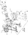
- the power tool 110 shown in FIG. 2is illustratively embodied as a cordless, electric impact tool (in particular, an electric, pistol-style impact tool).
- the power tool 110may be embodied as a pistol-grip impact tool, an in-line impact tool, or an angle impact tool, such as a right-angle impact tool.
- the power tool 110includes an impact mechanism 112 that is operable to drive rotation of an output drive 114 of the power tool 110 about an axis 116, as best seen in the cross-sectional side view of FIG. 6 .
- the power tool 110may be embodied as an electric power tool that does not include an impact mechanism, such as a corded or cordless electric drill, driver, or ratchet.
- the illustrative power tool 110includes a tool housing 118 that is broken away to show that the power tool 110 also includes a motor housing 120 and fasteners 122, as best seen in FIG. 2 .
- the tool housing 118 of the tool 110is not assembled separately from the motor housing 120 of the tool 110. Rather, the fasteners 122 are used to secure components of both the tool housing 118 and the motor housing 120 together, such that the motor housing 120 is supported by the tool housing 118.
- the tool housing 118includes a hammer case 152, a body 126, and a back cap 128, as shown in FIG. 2 .
- the body 126defines an interior space 130 in which the motor housing 120 is positioned and through which the fasteners 122 extend when the tool 110 is assembled.
- the hammer case 152is coupled to the body 126, when the tool 110 is assembled, to close off the interior space 130 and define an output end 134 of the tool 110.
- the hammer case 152is formed to include threaded recesses 170 that receive the threaded ends of the fasteners 122 when the tool 110 is assembled. As such, the hammer case 152 may be considered a "front housing" or "front cap” of the tool housing 118.
- the hammer case 152supports the impact mechanism 112 of the tool 110.
- the back cap 128is also coupled to the body 126, when the tool 110 is assembled, to close off the interior space 130 and define a back end 132 that is positioned opposite the output end 134 of the tool 110.
- the back cap 128is formed to include apertures 136 that extend through the back cap 128 and open into the interior space 130 when the tool 110 is assembled. These apertures 136 are sized to receive the fasteners 122 as shown in FIG. 2 .
- the body 126is illustratively formed from two mirror-image halves 126A, 126B, only one of which is shown in FIG. 2 . It should be appreciated, however, that in other embodiments, the body 126 may be formed from a single piece or from more than two pieces.
- the halves 126A, 126Bextend downwardly from the back cap 128 to define a handle 124 which may be grasped by a user of the power tool 110.
- the halves 126A, 126Beach extend between the hammer case 152 and the back cap 128, such that the body 126 supports the motor housing 120 when the tool 110 is assembled, as suggested by FIG. 2 .
- the halves 126A, 126B of the body 126are generally divided along a parting plane that passes through both the handle 124 and the motor housing 120.
- the body 126illustratively includes features 127 that are used to position the halves 126A, 126B relative to one another during assembly of the tool 110.
- each of the halves 126A, 126Bis formed to include a respective flange 127A, 127B that is received by one of a pair of corresponding channels 152A, 152B formed in the hammer case 152 of the tool housing 118 ( see Fig. 2 ).
- the halves 126A, 126Bare guided toward one another around the motor housing 120 ( see Fig. 2 ), thereby minimizing any gap between the halves 126A, 126B and facilitating engagement of the motor housing 120 ( see Fig. 2 ) by the body 126 during assembly of the tool 110.
- the features 127also include projections 127C-F that are provided on each of the halves 126A, 126B and received by the back cap 128 during assembly of the tool 110.
- the half 126Aincludes an upper projection 127C and a lower projection 127E
- the half 126Bincludes an upper projection 127D and a lower projection 127F.
- the halves 126A, 126Bare guided toward one another until the projections 127C, 127D align with and engage one another and the projections 127E, 127F align with and engage one another, thereby minimizing any gap between the halves 126A, 126B.
- the back cap 128is engaged with the halves 126A, 126B so that the projections 127C-F are received by slots 129 formed in the back cap 128 (one of which is shown in FIG. 5 ).
- the features 127therefore facilitate attachment of the halves 126A, 126B of the body 126 to the hammer case 152 and the back cap 128 to minimize any gap existing between the halves 126A, 126B during assembly of the tool 110, as shown in FIGS. 3-5 .
- the fasteners 122are used to secure the back cap 128 to the hammer case 152, with the halves 126A, 126B sandwiched between the back cap 128 and the hammer case 152, to assemble the tool housing 118 of the tool 110.
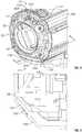
- the motor housing 120includes an end bell 138 that abuts the back cap 128 and an end bell 140 that abuts the hammer case 152 when the tool 110 is assembled.
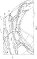
- the end bell 140is adjacent a transmission 160 of the power tool 110 that extends between the end bell 140 and the impact mechanism 112, as best seen in FIG. 6 .
- the end bells 138, 140cooperatively support a rotor 156 and a stator 148 of a motor 142 of the tool 110.
- the end bell 138is formed to include grooves 144 that extend through the end bell 138 parallel to the axis 116.
- the end bell 140is formed to include grooves 146 that extend through the end bell 140 parallel to the axis 116.
- the grooves 144 of the end bell 138are aligned with the grooves 146 of the end bell 140, both of which are aligned with the apertures 136 of the back cap 128 and with the recesses 170 formed in the hammer case 152.
- the end bell 138 of the motor housing 120 and the back cap 128 of the tool housing 118are illustratively separate components as shown in, and described above with reference to, FIG. 2 . It should be appreciated, however, that in other embodiments, the end bell 138 and the back cap 128 may be provided as a unitary or integral component. In other words, in some embodiments, the same component may serve as both the end bell 138 of the motor housing 120 and the back cap 128 of the tool housing 118.
- the motor 142is illustratively embodied as an electric motor, as suggested by FIG. 2 .
- the motor 142includes a stationary component, i.e., the stator 148, that is positioned between the end bells 138, 140.
- the motor 142also includes the rotor 156 which is configured to rotate about the axis 116 to drive rotation of the output drive 114 (via the transmission 160 and the impact mechanism 112).
- the stator 148defines channels 150 that extend through the stator 148 parallel to the axis 116.
- the channels 150 of the stator 148are aligned with the grooves 144, 146 of the end bells 138, 140, with the apertures 136 of the back cap 128, and with the recesses 170 formed in the hammer case 152.
- the hammer case 152 of the impact mechanism 112supports a hammer 151 of the impact mechanism 112.
- the hammer case 152is formed to include threaded recesses 170 that each receives a threaded end of one of the fasteners 122. These recesses 170 each extend parallel to the axis 116, as best seen in FIG. 6 .
- the recesses 170 of the hammer case 152are aligned with the channels 150 of the stator 148, the grooves 144, 146 of the end bells 138, 140, and the apertures 136 of the back cap 128.
- the fasteners 122are inserted through the apertures 136, the grooves 144, the channels 150, and the grooves 146, and into the recesses 170 when the tool 110 is assembled, as shown in FIGS. 2 and 6 .
- the fasteners 122secure the back cap 128 to the hammer case 152, with the body 126 sandwiched between the back cap 128 and hammer case 152, to form the tool housing 118.
- the fasteners 122secure the end bells 138, 140 around the stator 148 to form the motor housing 120. In that way, the fasteners 122 secure the tool housing 118 and the motor housing 120 together so that the motor housing 120 is supported by the tool housing 118.
- the fasteners 122illustratively extend in a direction indicated by arrow C that is parallel to a direction indicated by arrow D in which the motor 142 and the motor housing 120 extend, as shown in FIGS. 2 and 6 .
- the fasteners 122engage the back cap 128 and extend therefrom through the interior space 130 to the hammer case 152.
- the fasteners 122illustratively include four fasteners in the embodiment of FIGS. 2-6 . It should be appreciated, however, that in other embodiments, more or less than four fasteners may be used. Additionally, it should be appreciated that, in some embodiments, fasteners may not be used at all. Rather, clips or metal tie straps, or the like, may be used.
- the package size of the power tool 110may be smaller than the package size of the power tool 10.
- the motor housing 120 and the tool housing 118are secured together via one set of fasteners 122, the separate components used to secure the tool housing 12 and the motor housing 20 together may be avoided, and thus the package size of the power tool 110 may be smaller than the package size of the power tool 10.
Landscapes
- Engineering & Computer Science (AREA)
- Mechanical Engineering (AREA)
- Power Engineering (AREA)
- Portable Power Tools In General (AREA)
- Motor Or Generator Frames (AREA)
Description
- The present application relates to and claims priority to
U.S. Provisional Patent Application, Serial No. 62/171,768, filed on June 5, 2015 U.S. Patent Application, Serial No. 15/172,214, filed June 3, 2016 - The present disclosure relates, generally, to housings for power tools and, more particularly, to housings for cordless power tools, such as cordless impact tools.
- As prior art there may be mentioned:
US2012/138329 , which discloses a pneumatic impact wrench that includes a main body, a plastic casing provided for fixing a motor casing and a motor module, the motor module having a cylinder for installing a rotor, the rotor being extended from an axle and supported by a bearing, the motor casing having an external case with a hardness greater than that of the plastic casing, and the external case being hollow and penetrating both ends to form a chamber for accommodating and installing a cylinder, and the external case having a stop ring protruded from an internal wall of the chamber and provided for blocking the cylinder, and an external case cover installed at a rear end of the external case for coupling and covering the external case cover; DE102006000543 , which discloses a hand tool device having a multipart housing, which has a motor housing, forming an assembly opening, over which a stator of a motor defining an axis is inserted in the motor housing. The stator is fixed in the inserted position by an axial arrester, which is axially fixed by two clamping connections, which have two clamping elements, held on two tensioning housings provided on the motor housing. Two additional tensioning housings are provided on the motor housing, which have an axial offset to the former tensioning housings;US2003/121679 , which discloses a rigid preformed insert molded into a plastic housing for a power tool. The power tool further comprises a motor having a shaft, the motor being at least partly supported by the insert, and an impact clutch attached to the insert and operatively coupled to the motor shaft. The motor and clutch have a common axis, with the preformed insert located between the motor and the clutch. The insert fixedly secures the axis of the output shaft of the motor. The insert also forms a seal between the motor and clutch;US2013/062498 , which discloses a suspension device including a ring for hanging a power tool and a ring retaining member provided at an upper part of a housing of the power tool. The housing has a grip at a lower part thereof. The ring retaining member is configured such that the ring is movable between a standing position and a lying position and that the ring is retainable in the standing position;EP2062700 , which discloses a power tool housing assembly including a base housing segment and a cover housing segment generally symmetrical to the base housing segment, characterized in that: each housing segment comprises a plurality of assembly bosses defining a respective plurality of apertures accessible from an exterior of the housing assembly, the base housing segment further comprising at least one intermediate fastening boss defining an aperture accessible from an interior of the housing assembly; and a field case having at least one cooperating assembly fastening boss configured for attaching the field case to an interior of the base housing segment, wherein the field case, base housing segment, and cover housing segment cooperate to form a housing assembly that includes an end cap and a mid-handle grip integrally connected via a bridge section and having a longitudinal parting line; andEP2535150 , which discloses an impact tool in which a hammer case into which an output shaft of a motor is inserted is assembled to the front of a housing containing a stator core. In the hammer case, a spindle to which rotation is transmitted from the output shaft of the motor is provided. The rear end of the hammer case is coupled with a bearing box. In the housing, a partition wall through which the output shaft passes is provided between the stator core side and the hammer case side. On the housing, an air inlet is provided. An electric circuit board is provided on the front face of the stator core to close the front face with the output shaft passing therethrough. Between the electric circuit board and the partition wall, a waterproof member through which the output shaft passes is provided to close the gap therebetween.- Existing housings for power tools are typically sized to accommodate motor housings of motors included in the power tools. For example, some power tool housings may include two halves, sometimes referred to as "clam shells," which are secured together to hold the motor housing of the motor within the halves of the power tool housings. In such arrangements, the additional space occupied by the fasteners used to secure the halves of the power tool housings together may cause the size of the power tool housings to be undesirable in certain applications. Accordingly, the present disclosure relates to a power tools having a reduced size.
- To that end, an illustrative embodiment of the present disclosure provides a power tool which comprises a front housing, a plurality of fasteners, a back cap, a motor, and a motor housing. The front housing supports an output drive, and the back cap located opposite the front housing. The back cap includes a plurality of apertures each sized to receive one fastener of the plurality of fasteners. The motor housing supports a motor and is located between the front housing and the back cap. The motor includes a rotor that is configured to rotate about a motor axis to drive rotation of the output drive. The at least one fastener of the plurality of fasteners engages the back cap and is disposed in at least one of the plurality of apertures of the back cap. The motor housing includes a plurality of grooves that extend substantially parallel to the motor axis. One groove of the plurality of grooves is aligned with one aperture of the plurality of apertures of the back cap. Each fastener of the plurality of fasteners is disposed through one of the plurality of apertures of the back cap, along one groove of the plurality of grooves of the motor housing, and secures to the front housing coupling the front housing, the motor housing, and the back cap together. Lastly, the plurality of fasteners extends substantially parallel to the motor axis when coupling the front housing, the motor housing, and the back cap together.
- In the above and other embodiments of the present disclosure may also comprise: the front housing including a plurality of threaded recesses, wherein each threaded recess being aligned with one groove of the plurality of grooves in the motor housing and each threaded recess being configured to receive one fastener of the plurality of fasteners; a body that wraps around at least a portion of the motor housing between the front housing and the back cap; the body defining an interior space in which the motor housing is positioned and through which the plurality of fasteners extend when the front housing, the motor housing, and the back cap are coupled together; the body further including at least two body parts wherein each of the body parts wrap around at least a portion of the motor housing between the front housing and the back cap; at least one of the at least two body parts includes a flange that engages the front housing; and at least one of the at least two body parts includes a flange that engages the back cap.
- Another illustrative embodiment of the present disclosure provides a power tool that also comprises a front housing, a plurality of fasteners, a back cap, a motor, and a motor housing. The front housing supports an output drive, and the back cap is located opposite the front housing. The motor housing supports a motor and is located between the front housing and the back cap. The motor includes a rotor configured to rotate about a motor axis to drive rotation of the output drive. At least one fastener of the plurality of fasteners engages the back cap and secures the motor housing to the front housing. The plurality of fasteners also extends substantially parallel to the motor axis when coupling the front housing, the motor housing, and the back cap together.
- In the above and other embodiments of the present disclosure may also comprise: a body that wraps around at least a portion of the motor housing between the front housing and the back cap; the body defines an interior space in which the motor housing is positioned when the front housing, the motor housing, and the back cap are coupled together; the body further including at least two body parts wherein each of the body parts wraps around at least a portion of the motor housing between the front housing and the back cap; at least one of the at least two body parts includes a tab that engages the front housing; and at least one of the at least two body parts includes a tab that engages the back cap.
- Another illustrative embodiment of the present disclosure provides a power tool that comprises a front housing, an output drive, a back cap, a motor housing, a motor, and a plurality of fasteners. The front housing supports the output drive. The back cap is located opposite the front housing. The motor housing supports the motor. The motor includes a rotor configured to rotate about a motor axis to drive rotation of the output drive. The plurality of fasteners extends parallel to the motor axis, each of the plurality of fasteners engage the front housing and the motor housing, and the plurality of fasteners extends substantially parallel to the motor axis when coupling the front housing and the motor housing together.
- In the above and other embodiments of the present disclosure may also comprise: a back cap that includes a plurality of apertures each sized to receive one fastener of the plurality of fasteners; the motor housing being located between the front housing and the back cap; the motor housing includes a plurality of grooves that extends substantially parallel to the motor axis, and wherein one groove of the plurality of grooves is aligned with one aperture of a plurality of apertures disposed in the back cap; each fastener of the plurality of fasteners is disposed through one of a plurality of apertures disposed in the back cap, along one groove of a plurality of grooves on the motor housing, and secures to the front housing to couple the front housing, the motor housing, and the back cap together; a body that wraps around at least a portion of the motor housing adjacent the front housing, wherein the body defines an interior space in which the motor housing is positioned when the front housing and the motor housing are coupled together, and wherein the body is selected from the group consisting of at least one body part and a plurality of body parts; and the body including at least one tab that engages the front housing.
- The concepts described in the present disclosure are illustrated by way of example and not by way of limitation in the accompanying figures. For simplicity and clarity of illustration, elements illustrated in the figures are not necessarily drawn to scale. For example, the dimensions of some elements may be exaggerated relative to other elements for clarity. Further, where considered appropriate, reference labels may be repeated among the figures to indicate corresponding or analogous elements.
FIG. 1 is an exploded perspective view of various components held by a housing of a PRIOR ART power tool;FIG. 2 is a perspective view of a portion of an illustrative power tool according to the present disclosure;FIG. 3 is a detailed perspective view of an interface between components of a tool housing of the power tool ofFIG. 2 ;FIG. 4 is another detailed perspective view of an interface between other components of the tool housing of the power tool ofFIG. 2 ;FIG. 5 is a sectional view taken about line 5-5 ofFIG. 4 ; andFIG. 6 is a cross-sectional side view of a portion of the power tool ofFIG. 2 .- While the concepts of the present disclosure are susceptible to various modifications and alternative forms, specific exemplary embodiments thereof have been shown by way of example in the drawings and will herein be described in detail. It should be understood, however, that there is no intent to limit the concepts of the present disclosure to the particular forms disclosed, but on the contrary, the intention is to cover all modifications, equivalents, and alternatives falling within the spirit and scope of the present disclosure.
- Referring now to
FIG. 1 , a PRIORART power tool 10 is shown. Thepower tool 10 includes apower tool housing 12 that has a "clam-shell" construction, meaning that internal components of thepower tool 10, such as themotor 18 and themotor housing 20, are held by two halves or "clam shells" 14, 16 of thehousing 12 which are secured together (along with other housing components) to form thehousing 12. This "clam shell"housing 12 is generally divided along a parting plane that passes through both thehandle 28 of thepower tool 10 and the axis about which the rotor of themotor 18 rotates during operation (which, in this embodiment, is also the axis about which components of animpact mechanism 30 of thepower tool 10 rotate during operation). Components of themotor housing 20 are secured together separately from thehalves housing 20 that contains themotor 18. - The
halves housing 12 are configured to receivefasteners 22 to secure thehalves FIG. 1 . Specifically, thehalf 14 is formed to includeapertures 24, and thehalf 16 is formed to includeapertures 26. During assembly of thetool 10, thehalves fasteners 22 to be received by correspondingapertures halves fasteners 22 extend in a direction indicated by arrow A that is substantially perpendicular to a direction indicated by arrow B in which themotor 18 and themotor housing 20 extend (the arrow B being generally parallel to the axis about which both the rotor of themotor 18 and the components of theimpact mechanism 30 rotate during operation). - In the PRIOR ART design shown in
FIG. 1 , thefasteners 22 are positioned both above and below themotor 18 and themotor housing 20. In that way, thefasteners 22 extend around themotor 18 and the motor housing 20 (without passing through any component of themotor 18 or the motor housing 20). - The
halves fasteners 22 to extend around themotor 18 and themotor housing 20 when thetool 10 is assembled, as suggested by PRIOR ARTFIG. 1 . Due to the size of thehalves housing 12 may be undesirable in certain situations, such as when space constraints impeding the use of thetool 10 are present. Alternatives that enable the size ofhousing 12, and thus the package size of thepower tool 10, to be reduced would therefore be beneficial in such situations. - Referring now to
FIG. 2 , anillustrative power tool 110 according to the present disclosure is shown. Like thepower tool 10 of PRIOR ARTFIG. 1 , thepower tool 110 shown inFIG. 2 is illustratively embodied as a cordless, electric impact tool (in particular, an electric, pistol-style impact tool). In various embodiments, thepower tool 110 may be embodied as a pistol-grip impact tool, an in-line impact tool, or an angle impact tool, such as a right-angle impact tool. Thepower tool 110 includes animpact mechanism 112 that is operable to drive rotation of anoutput drive 114 of thepower tool 110 about anaxis 116, as best seen in the cross-sectional side view ofFIG. 6 . It should be appreciated, however, that in other embodiments, thepower tool 110 may be embodied as an electric power tool that does not include an impact mechanism, such as a corded or cordless electric drill, driver, or ratchet. - The
illustrative power tool 110 includes atool housing 118 that is broken away to show that thepower tool 110 also includes amotor housing 120 andfasteners 122, as best seen inFIG. 2 . In contrast to the PRIORART power tool 10 ofFIG. 1 , thetool housing 118 of thetool 110 is not assembled separately from themotor housing 120 of thetool 110. Rather, thefasteners 122 are used to secure components of both thetool housing 118 and themotor housing 120 together, such that themotor housing 120 is supported by thetool housing 118. - The
tool housing 118 includes ahammer case 152, abody 126, and aback cap 128, as shown inFIG. 2 . Thebody 126 defines aninterior space 130 in which themotor housing 120 is positioned and through which thefasteners 122 extend when thetool 110 is assembled. Thehammer case 152 is coupled to thebody 126, when thetool 110 is assembled, to close off theinterior space 130 and define anoutput end 134 of thetool 110. Thehammer case 152 is formed to include threadedrecesses 170 that receive the threaded ends of thefasteners 122 when thetool 110 is assembled. As such, thehammer case 152 may be considered a "front housing" or "front cap" of thetool housing 118. In the illustrative embodiment, thehammer case 152 supports theimpact mechanism 112 of thetool 110. Theback cap 128 is also coupled to thebody 126, when thetool 110 is assembled, to close off theinterior space 130 and define aback end 132 that is positioned opposite theoutput end 134 of thetool 110. Theback cap 128 is formed to includeapertures 136 that extend through theback cap 128 and open into theinterior space 130 when thetool 110 is assembled. Theseapertures 136 are sized to receive thefasteners 122 as shown inFIG. 2 . - The
body 126 is illustratively formed from two mirror-image halves FIG. 2 . It should be appreciated, however, that in other embodiments, thebody 126 may be formed from a single piece or from more than two pieces. Thehalves back cap 128 to define ahandle 124 which may be grasped by a user of thepower tool 110. Thehalves hammer case 152 and theback cap 128, such that thebody 126 supports themotor housing 120 when thetool 110 is assembled, as suggested byFIG. 2 . In the illustrative embodiment, thehalves body 126 are generally divided along a parting plane that passes through both thehandle 124 and themotor housing 120. - Referring now to
FIG. 3 , thebody 126 illustratively includesfeatures 127 that are used to position thehalves tool 110. Specifically, each of thehalves respective flange corresponding channels hammer case 152 of the tool housing 118 (seeFig. 2 ). When theflanges channels halves Fig. 2 ), thereby minimizing any gap between thehalves Fig. 2 ) by thebody 126 during assembly of thetool 110. - Referring now to
FIGS. 4-5 , thefeatures 127 also includeprojections 127C-F that are provided on each of thehalves back cap 128 during assembly of thetool 110. In the illustrative embodiment, thehalf 126A includes anupper projection 127C and alower projection 127E, while thehalf 126B includes anupper projection 127D and alower projection 127F. During assembly of thetool 110, thehalves projections projections halves projections 127C-F of thehalves back cap 128 is engaged with thehalves projections 127C-F are received byslots 129 formed in the back cap 128 (one of which is shown inFIG. 5 ). - The
features 127 therefore facilitate attachment of thehalves body 126 to thehammer case 152 and theback cap 128 to minimize any gap existing between thehalves tool 110, as shown inFIGS. 3-5 . Once thehalves hammer case 152 and theback cap 128 as discussed above, thefasteners 122 are used to secure theback cap 128 to thehammer case 152, with thehalves back cap 128 and thehammer case 152, to assemble thetool housing 118 of thetool 110. - Referring again to
FIG. 2 , themotor housing 120 includes anend bell 138 that abuts theback cap 128 and anend bell 140 that abuts thehammer case 152 when thetool 110 is assembled. Theend bell 140 is adjacent a transmission 160 of thepower tool 110 that extends between theend bell 140 and theimpact mechanism 112, as best seen inFIG. 6 . Theend bells rotor 156 and astator 148 of amotor 142 of thetool 110. Theend bell 138 is formed to includegrooves 144 that extend through theend bell 138 parallel to theaxis 116. Likewise, theend bell 140 is formed to includegrooves 146 that extend through theend bell 140 parallel to theaxis 116. When thetool 110 is assembled as shown inFIG. 2 , thegrooves 144 of theend bell 138 are aligned with thegrooves 146 of theend bell 140, both of which are aligned with theapertures 136 of theback cap 128 and with therecesses 170 formed in thehammer case 152. - The
end bell 138 of themotor housing 120 and theback cap 128 of thetool housing 118 are illustratively separate components as shown in, and described above with reference to,FIG. 2 . It should be appreciated, however, that in other embodiments, theend bell 138 and theback cap 128 may be provided as a unitary or integral component. In other words, in some embodiments, the same component may serve as both theend bell 138 of themotor housing 120 and theback cap 128 of thetool housing 118. - The
motor 142 is illustratively embodied as an electric motor, as suggested byFIG. 2 . Themotor 142 includes a stationary component, i.e., thestator 148, that is positioned between theend bells motor 142 also includes therotor 156 which is configured to rotate about theaxis 116 to drive rotation of the output drive 114 (via the transmission 160 and the impact mechanism 112). Thestator 148 defineschannels 150 that extend through thestator 148 parallel to theaxis 116. When thetool 110 is assembled as shown inFIGS. 2 and6 , thechannels 150 of thestator 148 are aligned with thegrooves end bells apertures 136 of theback cap 128, and with therecesses 170 formed in thehammer case 152. - Referring now to
FIGS. 2 and6 , thehammer case 152 of theimpact mechanism 112 supports ahammer 151 of theimpact mechanism 112. As noted above, thehammer case 152 is formed to include threadedrecesses 170 that each receives a threaded end of one of thefasteners 122. Theserecesses 170 each extend parallel to theaxis 116, as best seen inFIG. 6 . When thetool 110 is assembled as shown inFIGS. 2 and6 , therecesses 170 of thehammer case 152 are aligned with thechannels 150 of thestator 148, thegrooves end bells apertures 136 of theback cap 128. - The
fasteners 122 are inserted through theapertures 136, thegrooves 144, thechannels 150, and thegrooves 146, and into therecesses 170 when thetool 110 is assembled, as shown inFIGS. 2 and6 . Thefasteners 122 secure theback cap 128 to thehammer case 152, with thebody 126 sandwiched between theback cap 128 and hammercase 152, to form thetool housing 118. Additionally, thefasteners 122 secure theend bells stator 148 to form themotor housing 120. In that way, thefasteners 122 secure thetool housing 118 and themotor housing 120 together so that themotor housing 120 is supported by thetool housing 118. - The
fasteners 122 illustratively extend in a direction indicated by arrow C that is parallel to a direction indicated by arrow D in which themotor 142 and themotor housing 120 extend, as shown inFIGS. 2 and6 . Thefasteners 122 engage theback cap 128 and extend therefrom through theinterior space 130 to thehammer case 152. Thefasteners 122 illustratively include four fasteners in the embodiment ofFIGS. 2-6 . It should be appreciated, however, that in other embodiments, more or less than four fasteners may be used. Additionally, it should be appreciated that, in some embodiments, fasteners may not be used at all. Rather, clips or metal tie straps, or the like, may be used. - In one respect, because the
fasteners 122 extend through themotor 142 and themotor housing 120, rather than around themotor 142 and themotor housing 120, the package size of thepower tool 110 may be smaller than the package size of thepower tool 10. In another respect, because themotor housing 120 and thetool housing 118 are secured together via one set offasteners 122, the separate components used to secure thetool housing 12 and themotor housing 20 together may be avoided, and thus the package size of thepower tool 110 may be smaller than the package size of thepower tool 10. - While certain illustrative embodiments have been described in detail in the figures and the foregoing description, such an illustration and description is to be considered as exemplary and not restrictive in character, it being understood that only illustrative embodiments have been shown. There are a plurality of advantages of the present disclosure arising from the various features of the apparatus, systems, and methods described herein. Those of ordinary skill in the art may readily devise their own implementations of the apparatus, systems, and methods that incorporate one or more of the features of the present disclosure.
Claims (11)
- A power tool (110) comprising:a tool housing (118) comprising a front housing (152) supporting an output drive (114) and a back cap (128) defining a back end (132) of the power tool (110) located opposite the front housing (152);a motor housing (120) supporting an electric motor (142);wherein the motor housing (120) comprises a rear endbell (138) and a front endbell (140) that cooperatively support a stator (148) and a rotor (156) of the electric motor (142), the rotor (156) configured to rotate about a motor axis (116) to drive rotation of the output drive, wherein the motor housing (120) is located between the front housing (152) and the back cap (128);a plurality of fasteners (122);wherein the back cap (128) includes a plurality of apertures (136) each sized to receive one fastener of the plurality of fasteners (122);wherein the front endbell (140) and the rear endbell (138) each comprise a plurality of endbell grooves (144,146) that extend substantially parallel to the motor axis (116);wherein the stator (148) defines stator channels (150) that extend through the stator substantially parallel to the motor axis (116);wherein one endbell groove (146) of the plurality of endbell grooves (146) of the front endbell (140) and one endbell groove (144) of the plurality of endbell grooves (144) of the rear endbell (138) are aligned with both one stator channel (150) and one aperture (136) of the plurality of apertures (136) of the back cap (128);wherein each fastener of the plurality of fasteners (122) is disposed through one of the plurality of apertures (136) of the back cap (128), along one endbell groove (144) of the plurality of endbell grooves (144,146) of the rear endbell (138), along one stator channel (150) of the stator (148), along one endbell groove (146) of the plurality of endbell grooves (146) of the front endbell (140), and secures to the front housing to couple the front housing (152), the front endbell (140) of the motor housing (120), the stator (148), the rear endbell (138) of the motor housing (120) and the back cap (128) together; andwherein the plurality of fasteners (122) extend substantially parallel to the motor axis (116) when coupling the front housing (152), the front endbell (140) of the motor housing (120), the stator (148), the rear endbell (138) of the motor housing (120) and the back cap (128) together.
- The power tool (110) of Claim 1, wherein the front housing (152) includes a plurality of threaded recesses (177), wherein each threaded recess (177) is aligned with one endbell groove (146) of the plurality of endbell grooves (146) of the front endbell (140), with one endbell groove (144) of the plurality of endbell grooves (144) of the rear endbell (138) and with one stator channel (150), wherein each threaded recess (177) is configured to receive one fastener of the plurality of fasteners (122).
- The power tool (110) of Claim 1 or 2, wherein the tool housing (118) further comprises a body (126) that wraps around at least a portion of the motor housing (120) between the front housing (152) and the back cap (128).
- The power tool (110) of Claim 3, wherein the body (126) defines an interior space in which the motor housing (122) is positioned when the front housing (152), the front endbell 140, the stator 148, the rear endbell 138, and the back cap (128) are coupled together.
- The power tool (110) of Claim 4, wherein the plurality of fasteners (122) extend through the interior space when the front housing (152), the front endbell 140, the stator 148, the rear endbell 138, and the back cap (128) are coupled together.
- The power tool (110) of any one of Claims 3 to 5, wherein the body (126) comprises at least two body parts (126A, 126B) wherein each of the body parts (126A, 126B) wrap around at least a portion of the motor housing (120) between the front housing (152) and the back cap (128).
- The power tool (110) of Claim 6, wherein at least one of the at least two body parts (126A, 126B) includes a tab or flange that engages the front housing.
- The power tool of Claim 6 or 7, wherein at least one of the at least two body parts (126A, 126B) includes a tab or flange (127A, 127B) that engages the back cap (128).
- The power tool (110) of Claim 1 or 2, further comprising a body (126) that wraps around at least a portion of the motor housing (120) adjacent the front housing (152), wherein the body (126) defines an interior space in which the motor housing (120) is positioned when the front housing (152) and the motor housing (120) are coupled together, and wherein the body (126) is selected from the group consisting of at least one body part and a plurality of body parts.
- The power tool (110) of Claim 9, wherein the body (126) includes at least one tab that engages the front housing (152).
- The power tool (110) of any preceding Claim, wherein the power tool (110) does not include any further fasteners between the back cap (128), the rear endbell (138), the stator (148), the front endbell (140) or the front housing (152) in addition to the fasteners disposed through the plurality of apertures (136) of the back cap (128), along the plurality of endbell grooves (144) of the rear endbell (138), along the stator channels (150) of the stator (148), and along the plurality of endbell grooves (146) of the front endbell (140).
Applications Claiming Priority (2)
| Application Number | Priority Date | Filing Date | Title |
|---|---|---|---|
| US201562171768P | 2015-06-05 | 2015-06-05 | |
| PCT/US2016/035674WO2016196899A1 (en) | 2015-06-05 | 2016-06-03 | Power tool housings |
Publications (3)
| Publication Number | Publication Date |
|---|---|
| EP3302890A1 EP3302890A1 (en) | 2018-04-11 |
| EP3302890A4 EP3302890A4 (en) | 2019-03-06 |
| EP3302890B1true EP3302890B1 (en) | 2020-11-04 |
Family
ID=61201728
Family Applications (1)
| Application Number | Title | Priority Date | Filing Date |
|---|---|---|---|
| EP16804505.2AActiveEP3302890B1 (en) | 2015-06-05 | 2016-06-03 | Power tool housings |
Country Status (2)
| Country | Link |
|---|---|
| EP (1) | EP3302890B1 (en) |
| CN (1) | CN107735223B (en) |
Families Citing this family (3)
| Publication number | Priority date | Publication date | Assignee | Title |
|---|---|---|---|---|
| US10701820B1 (en)* | 2019-06-06 | 2020-06-30 | Fisher Controls International Llc | Tamper proof approaches for securing an enclosure |
| US11691261B2 (en)* | 2020-06-02 | 2023-07-04 | Snap-On Incorporated | Housing clamp for a power tool |
| US11654544B2 (en)* | 2020-06-03 | 2023-05-23 | Snap-On Incorporated | Insert for a power tool housing |
Citations (1)
| Publication number | Priority date | Publication date | Assignee | Title |
|---|---|---|---|---|
| US5200658A (en)* | 1990-11-28 | 1993-04-06 | Sumitomo Electric Industries, Ltd. | Electric motor with through-bolt guides for mounting |
Family Cites Families (11)
| Publication number | Priority date | Publication date | Assignee | Title |
|---|---|---|---|---|
| US3760209A (en)* | 1972-05-25 | 1973-09-18 | Vernco Corp | Split end bell for motor housing |
| EP1345737A2 (en)* | 2000-09-08 | 2003-09-24 | S.P. Air Kabusiki Kaisha | Pneumatic rotary tool |
| EP1787765A3 (en)* | 2001-01-23 | 2007-05-30 | BLACK & DECKER INC. | Housing with functional overmold |
| US6719067B2 (en)* | 2001-12-27 | 2004-04-13 | Taga Corporation | Insert for a plastic power tool housing |
| US7077218B2 (en)* | 2004-05-20 | 2006-07-18 | Black & Decker Inc. | Motor housing and assembly process for power tool |
| DE102006000543A1 (en)* | 2006-12-21 | 2008-06-26 | Hilti Ag | Hand tool device has multipart housing, which has motor housing, forming assembly opening, over which stator of motor is inserted in motor housing |
| US7770660B2 (en)* | 2007-11-21 | 2010-08-10 | Black & Decker Inc. | Mid-handle drill construction and assembly process |
| US7798245B2 (en)* | 2007-11-21 | 2010-09-21 | Black & Decker Inc. | Multi-mode drill with an electronic switching arrangement |
| US20120138329A1 (en)* | 2010-12-03 | 2012-06-07 | Storm Pneumatic Tool Co., Ltd. | Structure of pneumatic impact wrench |
| JP5728303B2 (en)* | 2011-06-15 | 2015-06-03 | 株式会社マキタ | Impact tool |
| JP2013059837A (en)* | 2011-09-14 | 2013-04-04 | Makita Corp | Power tool, and suspension device for the power tool |
- 2016
- 2016-06-03EPEP16804505.2Apatent/EP3302890B1/enactiveActive
- 2016-06-03CNCN201680031739.6Apatent/CN107735223B/enactiveActive
Patent Citations (1)
| Publication number | Priority date | Publication date | Assignee | Title |
|---|---|---|---|---|
| US5200658A (en)* | 1990-11-28 | 1993-04-06 | Sumitomo Electric Industries, Ltd. | Electric motor with through-bolt guides for mounting |
Also Published As
| Publication number | Publication date |
|---|---|
| CN107735223A (en) | 2018-02-23 |
| CN107735223B (en) | 2022-01-11 |
| EP3302890A4 (en) | 2019-03-06 |
| EP3302890A1 (en) | 2018-04-11 |
Similar Documents
| Publication | Publication Date | Title |
|---|---|---|
| US11707831B2 (en) | Power tool housings | |
| EP3302890B1 (en) | Power tool housings | |
| CN106926096B (en) | Angle grinder | |
| EP3587039B1 (en) | Work tool | |
| US7770660B2 (en) | Mid-handle drill construction and assembly process | |
| US6082468A (en) | Interchangeable grips for power hand tools | |
| US8415842B2 (en) | Power tool | |
| US8952581B2 (en) | Electric tools | |
| WO2010001814A1 (en) | Cable mounting structure for electric apparatus | |
| EP2139095B1 (en) | Power tool including hybrid electric motor design | |
| US20140196921A1 (en) | Power tool and auxiliary handle member | |
| JP2013000828A (en) | Impact tool | |
| JP2005329537A (en) | Motor housing for impact wrench and its assembling method | |
| US9692271B2 (en) | Electric motor | |
| JP2000341903A (en) | Motor housing structure | |
| US12366077B2 (en) | Concrete vibrator | |
| TWI243728B (en) | Modular power tool | |
| CN217063416U (en) | Brushless motor and electric tool | |
| CN116365787A (en) | Electric working machine | |
| KR100551615B1 (en) | Automotive Alternator | |
| US20090101761A1 (en) | Hand-held electrical power tool with flexural protection member | |
| ES2982573T3 (en) | Hand-held power machine tool | |
| CN115972156A (en) | Hand-held electric tool | |
| JP2004173435A (en) | Motor housing and assembling method of motor | |
| WO2020181768A1 (en) | Electric screwdriver |
Legal Events
| Date | Code | Title | Description |
|---|---|---|---|
| STAA | Information on the status of an ep patent application or granted ep patent | Free format text:STATUS: THE INTERNATIONAL PUBLICATION HAS BEEN MADE | |
| PUAI | Public reference made under article 153(3) epc to a published international application that has entered the european phase | Free format text:ORIGINAL CODE: 0009012 | |
| STAA | Information on the status of an ep patent application or granted ep patent | Free format text:STATUS: REQUEST FOR EXAMINATION WAS MADE | |
| 17P | Request for examination filed | Effective date:20171222 | |
| AK | Designated contracting states | Kind code of ref document:A1 Designated state(s):AL AT BE BG CH CY CZ DE DK EE ES FI FR GB GR HR HU IE IS IT LI LT LU LV MC MK MT NL NO PL PT RO RS SE SI SK SM TR | |
| AX | Request for extension of the european patent | Extension state:BA ME | |
| RIN1 | Information on inventor provided before grant (corrected) | Inventor name:NAKSEN, DENNIS Inventor name:LEAVITT, DOUGLAS FORNELL Inventor name:JOHNSON, JOSHUA ODELL Inventor name:BARTOSZEK, JASON CHRISTOPHER Inventor name:ELY, SEAN C. | |
| DAV | Request for validation of the european patent (deleted) | ||
| DAX | Request for extension of the european patent (deleted) | ||
| A4 | Supplementary search report drawn up and despatched | Effective date:20190204 | |
| RIC1 | Information provided on ipc code assigned before grant | Ipc:H02K 9/00 20060101ALI20190129BHEP Ipc:B25F 5/02 20060101AFI20190129BHEP | |
| RAP1 | Party data changed (applicant data changed or rights of an application transferred) | Owner name:INGERSOLL-RAND INDUSTRIAL U.S., INC. | |
| GRAP | Despatch of communication of intention to grant a patent | Free format text:ORIGINAL CODE: EPIDOSNIGR1 | |
| STAA | Information on the status of an ep patent application or granted ep patent | Free format text:STATUS: GRANT OF PATENT IS INTENDED | |
| INTG | Intention to grant announced | Effective date:20200527 | |
| GRAS | Grant fee paid | Free format text:ORIGINAL CODE: EPIDOSNIGR3 | |
| GRAA | (expected) grant | Free format text:ORIGINAL CODE: 0009210 | |
| STAA | Information on the status of an ep patent application or granted ep patent | Free format text:STATUS: THE PATENT HAS BEEN GRANTED | |
| AK | Designated contracting states | Kind code of ref document:B1 Designated state(s):AL AT BE BG CH CY CZ DE DK EE ES FI FR GB GR HR HU IE IS IT LI LT LU LV MC MK MT NL NO PL PT RO RS SE SI SK SM TR | |
| REG | Reference to a national code | Ref country code:GB Ref legal event code:FG4D | |
| REG | Reference to a national code | Ref country code:CH Ref legal event code:EP | |
| REG | Reference to a national code | Ref country code:AT Ref legal event code:REF Ref document number:1330195 Country of ref document:AT Kind code of ref document:T Effective date:20201115 | |
| REG | Reference to a national code | Ref country code:IE Ref legal event code:FG4D | |
| REG | Reference to a national code | Ref country code:DE Ref legal event code:R096 Ref document number:602016047319 Country of ref document:DE | |
| REG | Reference to a national code | Ref country code:NL Ref legal event code:MP Effective date:20201104 | |
| REG | Reference to a national code | Ref country code:AT Ref legal event code:MK05 Ref document number:1330195 Country of ref document:AT Kind code of ref document:T Effective date:20201104 | |
| PG25 | Lapsed in a contracting state [announced via postgrant information from national office to epo] | Ref country code:NO Free format text:LAPSE BECAUSE OF FAILURE TO SUBMIT A TRANSLATION OF THE DESCRIPTION OR TO PAY THE FEE WITHIN THE PRESCRIBED TIME-LIMIT Effective date:20210204 Ref country code:PT Free format text:LAPSE BECAUSE OF FAILURE TO SUBMIT A TRANSLATION OF THE DESCRIPTION OR TO PAY THE FEE WITHIN THE PRESCRIBED TIME-LIMIT Effective date:20210304 Ref country code:RS Free format text:LAPSE BECAUSE OF FAILURE TO SUBMIT A TRANSLATION OF THE DESCRIPTION OR TO PAY THE FEE WITHIN THE PRESCRIBED TIME-LIMIT Effective date:20201104 Ref country code:FI Free format text:LAPSE BECAUSE OF FAILURE TO SUBMIT A TRANSLATION OF THE DESCRIPTION OR TO PAY THE FEE WITHIN THE PRESCRIBED TIME-LIMIT Effective date:20201104 Ref country code:GR Free format text:LAPSE BECAUSE OF FAILURE TO SUBMIT A TRANSLATION OF THE DESCRIPTION OR TO PAY THE FEE WITHIN THE PRESCRIBED TIME-LIMIT Effective date:20210205 | |
| PG25 | Lapsed in a contracting state [announced via postgrant information from national office to epo] | Ref country code:SE Free format text:LAPSE BECAUSE OF FAILURE TO SUBMIT A TRANSLATION OF THE DESCRIPTION OR TO PAY THE FEE WITHIN THE PRESCRIBED TIME-LIMIT Effective date:20201104 Ref country code:BG Free format text:LAPSE BECAUSE OF FAILURE TO SUBMIT A TRANSLATION OF THE DESCRIPTION OR TO PAY THE FEE WITHIN THE PRESCRIBED TIME-LIMIT Effective date:20210204 Ref country code:IS Free format text:LAPSE BECAUSE OF FAILURE TO SUBMIT A TRANSLATION OF THE DESCRIPTION OR TO PAY THE FEE WITHIN THE PRESCRIBED TIME-LIMIT Effective date:20210304 Ref country code:LV Free format text:LAPSE BECAUSE OF FAILURE TO SUBMIT A TRANSLATION OF THE DESCRIPTION OR TO PAY THE FEE WITHIN THE PRESCRIBED TIME-LIMIT Effective date:20201104 Ref country code:PL Free format text:LAPSE BECAUSE OF FAILURE TO SUBMIT A TRANSLATION OF THE DESCRIPTION OR TO PAY THE FEE WITHIN THE PRESCRIBED TIME-LIMIT Effective date:20201104 Ref country code:ES Free format text:LAPSE BECAUSE OF FAILURE TO SUBMIT A TRANSLATION OF THE DESCRIPTION OR TO PAY THE FEE WITHIN THE PRESCRIBED TIME-LIMIT Effective date:20201104 Ref country code:AT Free format text:LAPSE BECAUSE OF FAILURE TO SUBMIT A TRANSLATION OF THE DESCRIPTION OR TO PAY THE FEE WITHIN THE PRESCRIBED TIME-LIMIT Effective date:20201104 | |
| REG | Reference to a national code | Ref country code:LT Ref legal event code:MG9D | |
| PG25 | Lapsed in a contracting state [announced via postgrant information from national office to epo] | Ref country code:HR Free format text:LAPSE BECAUSE OF FAILURE TO SUBMIT A TRANSLATION OF THE DESCRIPTION OR TO PAY THE FEE WITHIN THE PRESCRIBED TIME-LIMIT Effective date:20201104 | |
| PG25 | Lapsed in a contracting state [announced via postgrant information from national office to epo] | Ref country code:SK Free format text:LAPSE BECAUSE OF FAILURE TO SUBMIT A TRANSLATION OF THE DESCRIPTION OR TO PAY THE FEE WITHIN THE PRESCRIBED TIME-LIMIT Effective date:20201104 Ref country code:RO Free format text:LAPSE BECAUSE OF FAILURE TO SUBMIT A TRANSLATION OF THE DESCRIPTION OR TO PAY THE FEE WITHIN THE PRESCRIBED TIME-LIMIT Effective date:20201104 Ref country code:SM Free format text:LAPSE BECAUSE OF FAILURE TO SUBMIT A TRANSLATION OF THE DESCRIPTION OR TO PAY THE FEE WITHIN THE PRESCRIBED TIME-LIMIT Effective date:20201104 Ref country code:LT Free format text:LAPSE BECAUSE OF FAILURE TO SUBMIT A TRANSLATION OF THE DESCRIPTION OR TO PAY THE FEE WITHIN THE PRESCRIBED TIME-LIMIT Effective date:20201104 Ref country code:CZ Free format text:LAPSE BECAUSE OF FAILURE TO SUBMIT A TRANSLATION OF THE DESCRIPTION OR TO PAY THE FEE WITHIN THE PRESCRIBED TIME-LIMIT Effective date:20201104 Ref country code:EE Free format text:LAPSE BECAUSE OF FAILURE TO SUBMIT A TRANSLATION OF THE DESCRIPTION OR TO PAY THE FEE WITHIN THE PRESCRIBED TIME-LIMIT Effective date:20201104 | |
| REG | Reference to a national code | Ref country code:DE Ref legal event code:R097 Ref document number:602016047319 Country of ref document:DE | |
| PG25 | Lapsed in a contracting state [announced via postgrant information from national office to epo] | Ref country code:DK Free format text:LAPSE BECAUSE OF FAILURE TO SUBMIT A TRANSLATION OF THE DESCRIPTION OR TO PAY THE FEE WITHIN THE PRESCRIBED TIME-LIMIT Effective date:20201104 | |
| PLBE | No opposition filed within time limit | Free format text:ORIGINAL CODE: 0009261 | |
| STAA | Information on the status of an ep patent application or granted ep patent | Free format text:STATUS: NO OPPOSITION FILED WITHIN TIME LIMIT | |
| 26N | No opposition filed | Effective date:20210805 | |
| PG25 | Lapsed in a contracting state [announced via postgrant information from national office to epo] | Ref country code:IT Free format text:LAPSE BECAUSE OF FAILURE TO SUBMIT A TRANSLATION OF THE DESCRIPTION OR TO PAY THE FEE WITHIN THE PRESCRIBED TIME-LIMIT Effective date:20201104 Ref country code:AL Free format text:LAPSE BECAUSE OF FAILURE TO SUBMIT A TRANSLATION OF THE DESCRIPTION OR TO PAY THE FEE WITHIN THE PRESCRIBED TIME-LIMIT Effective date:20201104 Ref country code:NL Free format text:LAPSE BECAUSE OF FAILURE TO SUBMIT A TRANSLATION OF THE DESCRIPTION OR TO PAY THE FEE WITHIN THE PRESCRIBED TIME-LIMIT Effective date:20201104 | |
| PG25 | Lapsed in a contracting state [announced via postgrant information from national office to epo] | Ref country code:SI Free format text:LAPSE BECAUSE OF FAILURE TO SUBMIT A TRANSLATION OF THE DESCRIPTION OR TO PAY THE FEE WITHIN THE PRESCRIBED TIME-LIMIT Effective date:20201104 | |
| PGFP | Annual fee paid to national office [announced via postgrant information from national office to epo] | Ref country code:GB Payment date:20210813 Year of fee payment:6 | |
| PG25 | Lapsed in a contracting state [announced via postgrant information from national office to epo] | Ref country code:MC Free format text:LAPSE BECAUSE OF FAILURE TO SUBMIT A TRANSLATION OF THE DESCRIPTION OR TO PAY THE FEE WITHIN THE PRESCRIBED TIME-LIMIT Effective date:20201104 | |
| REG | Reference to a national code | Ref country code:CH Ref legal event code:PL | |
| REG | Reference to a national code | Ref country code:BE Ref legal event code:MM Effective date:20210630 | |
| PG25 | Lapsed in a contracting state [announced via postgrant information from national office to epo] | Ref country code:LU Free format text:LAPSE BECAUSE OF NON-PAYMENT OF DUE FEES Effective date:20210603 | |
| PG25 | Lapsed in a contracting state [announced via postgrant information from national office to epo] | Ref country code:LI Free format text:LAPSE BECAUSE OF NON-PAYMENT OF DUE FEES Effective date:20210630 Ref country code:IE Free format text:LAPSE BECAUSE OF NON-PAYMENT OF DUE FEES Effective date:20210603 Ref country code:CH Free format text:LAPSE BECAUSE OF NON-PAYMENT OF DUE FEES Effective date:20210630 | |
| PG25 | Lapsed in a contracting state [announced via postgrant information from national office to epo] | Ref country code:IS Free format text:LAPSE BECAUSE OF FAILURE TO SUBMIT A TRANSLATION OF THE DESCRIPTION OR TO PAY THE FEE WITHIN THE PRESCRIBED TIME-LIMIT Effective date:20210304 | |
| PG25 | Lapsed in a contracting state [announced via postgrant information from national office to epo] | Ref country code:BE Free format text:LAPSE BECAUSE OF NON-PAYMENT OF DUE FEES Effective date:20210630 | |
| GBPC | Gb: european patent ceased through non-payment of renewal fee | Effective date:20220603 | |
| PG25 | Lapsed in a contracting state [announced via postgrant information from national office to epo] | Ref country code:HU Free format text:LAPSE BECAUSE OF FAILURE TO SUBMIT A TRANSLATION OF THE DESCRIPTION OR TO PAY THE FEE WITHIN THE PRESCRIBED TIME-LIMIT; INVALID AB INITIO Effective date:20160603 Ref country code:GB Free format text:LAPSE BECAUSE OF NON-PAYMENT OF DUE FEES Effective date:20220603 | |
| P01 | Opt-out of the competence of the unified patent court (upc) registered | Effective date:20230523 | |
| PG25 | Lapsed in a contracting state [announced via postgrant information from national office to epo] | Ref country code:CY Free format text:LAPSE BECAUSE OF FAILURE TO SUBMIT A TRANSLATION OF THE DESCRIPTION OR TO PAY THE FEE WITHIN THE PRESCRIBED TIME-LIMIT Effective date:20201104 | |
| PG25 | Lapsed in a contracting state [announced via postgrant information from national office to epo] | Ref country code:MK Free format text:LAPSE BECAUSE OF FAILURE TO SUBMIT A TRANSLATION OF THE DESCRIPTION OR TO PAY THE FEE WITHIN THE PRESCRIBED TIME-LIMIT Effective date:20201104 | |
| PG25 | Lapsed in a contracting state [announced via postgrant information from national office to epo] | Ref country code:TR Free format text:LAPSE BECAUSE OF FAILURE TO SUBMIT A TRANSLATION OF THE DESCRIPTION OR TO PAY THE FEE WITHIN THE PRESCRIBED TIME-LIMIT Effective date:20201104 | |
| PGFP | Annual fee paid to national office [announced via postgrant information from national office to epo] | Ref country code:DE Payment date:20240628 Year of fee payment:9 | |
| PG25 | Lapsed in a contracting state [announced via postgrant information from national office to epo] | Ref country code:MT Free format text:LAPSE BECAUSE OF FAILURE TO SUBMIT A TRANSLATION OF THE DESCRIPTION OR TO PAY THE FEE WITHIN THE PRESCRIBED TIME-LIMIT Effective date:20201104 | |
| PGFP | Annual fee paid to national office [announced via postgrant information from national office to epo] | Ref country code:FR Payment date:20250627 Year of fee payment:10 |