EP3300637A1 - One-piece product carrying tray - Google Patents
One-piece product carrying trayDownload PDFInfo
- Publication number
- EP3300637A1 EP3300637A1EP17173642.4AEP17173642AEP3300637A1EP 3300637 A1EP3300637 A1EP 3300637A1EP 17173642 AEP17173642 AEP 17173642AEP 3300637 A1EP3300637 A1EP 3300637A1
- Authority
- EP
- European Patent Office
- Prior art keywords
- tray
- cover layer
- layer
- tab
- bottom layer
- Prior art date
- Legal status (The legal status is an assumption and is not a legal conclusion. Google has not performed a legal analysis and makes no representation as to the accuracy of the status listed.)
- Granted
Links
- 238000003780insertionMethods0.000claimsabstractdescription41
- 230000037431insertionEffects0.000claimsabstractdescription41
- 230000000087stabilizing effectEffects0.000claimsdescription27
- 230000001419dependent effectEffects0.000abstractdescription2
- 238000002360preparation methodMethods0.000abstractdescription2
- 230000006641stabilisationEffects0.000description3
- 238000011105stabilizationMethods0.000description3
- 238000010276constructionMethods0.000description1
- 239000003292glueSubstances0.000description1
- 239000000463materialSubstances0.000description1
- 230000002787reinforcementEffects0.000description1
- 238000004804windingMethods0.000description1
Images


Classifications
- A—HUMAN NECESSITIES
- A47—FURNITURE; DOMESTIC ARTICLES OR APPLIANCES; COFFEE MILLS; SPICE MILLS; SUCTION CLEANERS IN GENERAL
- A47B—TABLES; DESKS; OFFICE FURNITURE; CABINETS; DRAWERS; GENERAL DETAILS OF FURNITURE
- A47B96/00—Details of cabinets, racks or shelf units not covered by a single one of groups A47B43/00 - A47B95/00; General details of furniture
- A47B96/02—Shelves
- A47B96/021—Structural features of shelf bases
- A—HUMAN NECESSITIES
- A47—FURNITURE; DOMESTIC ARTICLES OR APPLIANCES; COFFEE MILLS; SPICE MILLS; SUCTION CLEANERS IN GENERAL
- A47F—SPECIAL FURNITURE, FITTINGS, OR ACCESSORIES FOR SHOPS, STOREHOUSES, BARS, RESTAURANTS OR THE LIKE; PAYING COUNTERS
- A47F5/00—Show stands, hangers, or shelves characterised by their constructional features
- A47F5/10—Adjustable or foldable or dismountable display stands
- A47F5/11—Adjustable or foldable or dismountable display stands made of cardboard, paper or the like
Definitions
- the inventionrelates to a load-bearing tray made of corrugated cardboard having a cover layer, a bottom layer, two longitudinal side walls and possibly insertion tabs for attaching the tray in a display case and a one-piece punched product for the preparation of the tray.
- POSpoint-of-sale
- the displaysare constructed like a shelf and usually have a display casing and shelves, in the form of trays or trays, which are inserted into the display case, hung or inserted. If a higher stability for the shelves is desired or if no upstand is necessary or desired as with the tray, shelves are used. These usually consist of a tray cover and a tray insert. By this construction, a high rigidity and stability can be achieved. The disadvantage is that two components and thus two blanks are needed. The shell must be glued and through the insert the tray has a significant weight.
- tray with Tablarhülle and Tablareinlageis in the EP 1 961 344 A1 described.
- the tray insertconsists of three times folded corrugated cardboard, which is glued. This four-layer tray insert is packed in the tray cover, pinned and glued in this. There are two blanks necessary, which must be processed with several complex steps to obtain the finished tray.
- the object of the present inventionis to provide a tray which has high rigidity and high stability with low weight.
- the trayshould continue to be inexpensive to produce, easy to transport and as universal as possible be used in various displays.
- the objectis achieved by a one-piece stamped product according to claim 1 and a tray according to claim 9.
- the one-piece stamped article according to the invention for a load-bearing traycomprises a cover layer, a bottom layer, at least three longitudinal side walls and, if appropriate, plug-in tabs for fastening the tray in a display casing.
- the diecutis made of cardboard or corrugated cardboard, preferably corrugated cardboard.
- the stamped productconsists of a single-walled corrugated cardboard and the running direction of the corrugated cardboard shaft runs transversely across the stamped product, i. the troughs and wave crests are parallel to the long sides of the top layers and the bottom layer.
- the stamped bodyconsists of EB-wave, B-wave, E-wave or EE-wave, in particular EE-wave.
- the cover layer of the stamped article according to the inventionhas an outer cover layer and a second, inner cover layer, wherein the inner cover layer is preferably congruent with the outer cover layer or the inner cover layer is pulled inwards on the short sides, e.g. around 5-10 mm.
- the outer stiffening tabspreferably hang on the inner cover layer and are then locked in the small slots of the bottom layer.
- the inner cover layeralso has at least one insertion slot for receiving a stiffening strap.
- the stamped sheethas at least one stiffening tab, which is part of the bottom layer and in the sheet position at the level of the insertion slot.
- the stamped product according to the inventionalso has two stabilizing tabs which are each articulated on a transverse side of the cover layer via a folding edge.
- the top layer and the bottom layerpreferably have a rectangular floor plan.
- the stamped product according to the inventionhas exactly one insertion slot and a corresponding stiffening strap.
- the insertion slotis preferably arranged centrally in the inner cover layer, particularly preferably parallel to the transverse sides.
- the stiffening strappreferably extends over the entire width of the bottom layer.
- the stamped product according to the inventionhas at least one closure tab, which is preferably articulated on a longitudinal side of a cover layer.
- the punched sheet according to the inventionhas on each transverse side at least one lateral insertion tab and on the rear longitudinal side at least one rear insertion tab with which the tray can be hung in a slotted display jacket.
- the tray of corrugated board according to the inventionis a product-carrying tray that is used in a display.
- Product carrying within the meaning of the inventionmeans that goods or product are placed on the tray and the tray carries the weight of this product or goods. For this it must have sufficient stability, rigidity and strength.
- the tray according to the inventioncan be plugged into a display case, hung or inserted.
- the tray according to the inventionhas a cover layer, a bottom layer, two longitudinal side walls and possibly insertion tabs for attaching the tray in a display casing.
- the tray according to the inventionhas a cover layer of an outer cover layer and an inner cover layer, which rest on one another, wherein the inner cover layer is preferably congruent to the outer cover layer.
- the inner cover layerhas at least one insertion slot, which serves for receiving at least one stiffening strap.
- the stiffening tabis part of the bottom layer, wherein the stiffening tab is attached to the bottom layer at the level of the insertion slot.
- the stiffening tabis preferably punched out of the bottom layer and forms a surface with the bottom layer before unfolding.
- the stiffening tabengages in the insertion slot of the inner cover layer.
- the tray according to the inventionfurther comprises two stabilizing tabs, which are each articulated on a transverse side of the tray via a folding edge to the lower of the two cover layers, which are folded into the tray 90 ° and preferably locked in opposite slots in the bottom layer.
- the tray according to the inventionpreferably consists of double-sided corrugated board.
- the running direction of the shaft of the corrugated boardruns across the tray, i. the waves are parallel to the longitudinal side of the tray.
- the tray of the inventionconsists of two-wave corrugated board, in particular EE wave.
- the tray according to the inventionpreferably consists in cross section of three layers of EE wave, which form by winding out. Two layers then give the top layers, including - depending on the desired tray thickness - air and a layer results in the bottom layer.
- the tray according to the inventionhas exactly one insertion slot and the insertion slot is preferably arranged centrally in the inner cover layer, preferably parallel to the transverse sides (Q).
- the stiffening tabdivides the tray into 2 parts in this embodiment. Depending on the positioning of the insertion slot, the parts are different sizes or the same size.
- the trayhas a plurality of insertion slots and a plurality of stiffening tabs.
- the stiffening tabruns in one embodiment over the entire width of the bottom layer.
- ithas a rectangular floor plan.
- the floor plan of the stiffening tabis congruent to the stabilizing tabs when they are formed single-walled.
- the stabilizing tabsare made double folded
- the two outer stabilizing tabshave a creasing edge, which serves to bend the tab 90 ° and stiffen so as a grooved surface is torsionally rigid.
- the 90 ° bendalso makes the flap easier to insert and lock.
- the height of the stabilizing flapcorresponds to this Case prefers the height of lower cover layer to ground layer.
- the height of the lateral stabilizing tabsis the distance between the two creases, with the last tab portion being angled.
- the stabilizing flaphas a folding edge which runs parallel to the transverse side over the entire width and divides the stabilizing flap in the middle.
- the tray according to the inventionhas at least one locking tab, which is preferably articulated to a longitudinal side of a cover layer.
- the closure flapis used when unfolding the tray from the diecut to attach the outer ceiling wall to the inner ceiling wall and to close the tray.
- the tray according to the inventionhas on each transverse side at least one lateral insertion tab and / or on the rear longitudinal side at least one rear insertion tab, with which the tray can be hung in a slotted display jacket.
- the tray according to the inventionpreferably has at least two lateral insertion tabs on each transverse side. Rear tabs are preferably used in addition, if a heavy weight on the tray loads and additional support is desired.
- the product-carrying tray according to the inventionis preferably hung by means of lateral insertion tabs in a slotted display casing.
- additional rear tabscarry weight in the rear area.
- the tray according to the inventionis preferably unfolded from a stamped product according to the invention.
- the rigidity of the tray according to the inventionis given by the direction of the shaft across the tray.
- the stability of the load-bearing cover layeris ensured by the stabilizing tabs, which are pressed into the tray at 90 ° and locked with an extension in a stabilizing slot.
- the at least one stiffening flapis pressed in from the bottom layer, wherein optionally several tabs can be introduced. These also shape that Tray completely off.
- the tray according to the inventionis so stable that it does not sag or deform when used properly and can not be pressed.
- tabs - later "invisible" -hang on the inner cover layer and lock in slots on the underside of the shelf.
- the tray according to the inventionhas a number of advantages over the known trays from Tablarhülle and Tablareinlage.
- the tray according to the inventioncan be punched and shipped without further processing directly on pallet lying flat. There is no glue and it does not need to be staggered staggered.
- the height of the tray according to the inventionis very variable, since the height is not dependent on the tray insert. This means that trays that are several centimeters higher can also be converted.
- the stiffnessis comparable to the conventional trays, the weight being lower because of the smaller amount of material.
- FIG. 1shows a punched product according to the invention 100.
- An outer cover layer 2a first longitudinal side wall 5 is articulated.
- a bottom layer 4is articulated.
- a stiffening tab 11can be seen, which is stamped out of the bottom layer 4 and is connected via a folding edge F with this.
- the bottom layer 4has lateral plug-in tabs 8a and 8b on both lateral sides Q and Q '.
- the bottom layer 4has two rear insertion tabs 9a and 9b.
- a further longitudinal side wall 6is articulated via a folding edge. This is articulated in its opposite side via a further folding edge to the inner cover layer 3.
- the inner cover layer 3has a slot 10 in the center. On its further longitudinal side a further longitudinal side wall 7 is articulated. At the transverse sides of the inner cover layer 3 are the stabilizing tabs 12 and 13.
- the stabilizing tabsare here designed as a 90 ° folding, i. the stabilizing tabs have a central folding edge along which the two parts of the stabilizing tabs 12 a and 12 b and 13 a and 13 b can be folded onto each other. In the middle of the folded edge is a respective extension 15, with which the stabilizing straps are locked in stabilizing slots 16 in the bottom layer 4.
- the punched product 100also has 2 closure tabs 14, which are articulated on the longitudinal side of the outer cover layer 2.
- the arrow(the shaft running symbol shows the running direction W of the waves in the shaft position, for which a part of bottom layer 4 is shown open.
- FIG. 2shows a perspective view of a tray 1 according to the invention.
- the upper sideis formed by the outer cover layer 2. Dashed lines indicate the position of the insertion slot located below the cover layer 10.
- On the front pageis also a side tab 8 can be seen.
- In the transverse sidealso the outer part of the stabilizing tabs 13 can be seen, which is pressed into the interior of the tray 1.
- FIG. 3shows the bottom of the tray 1 according to the invention FIG. 2 ,
- the bottom layer 4has a punched-out center, which has the shape of the stiffening tab 11.
- the stiffening tab 11is folded by 90 ° in the tray and in the insertion slot 10 (not shown) locked.
- the undersides of the lateral insertion tabs 8can be seen.
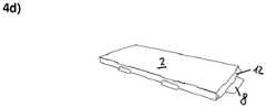
- FIGS. 4a, 4b, 4c and 4dIt is shown how from the punched 100 according to the invention the tray 1 according to the invention is unfolded.
- the inner cover layer 3folded in the direction of the bottom layer 4, until the longitudinal side wall 7 touches the bottom layer 4.
- the outer cover layer 2is folded in the direction of the inner cover layer 3.
- the locking tab 14are erected and to be plugged into the openings 17 for closing.
- Figure 4cshows the tray 1 according to the invention just before the locking tab 14 are inserted into the openings 17 to close the tray.
- the stabilizing tab 12is folded into the interior of the tray 1 and fixed there in the stabilizing slots 16 (not shown). Finally, the stiffening tab 11 is erected from the bottom layer 4 and inserted in the insertion slot 11.
- shelf 1 dIECUT100 outer cover layer 2 inner cover layer 3 bottom layer 4 Longitudinal side wall 5, 6, 7 lateral tabs 8th rear tabs 9 Slot in cover layer 10 stiffening flap 11 stabilization tab 12 stabilization tab 13 flap 14 extension 15 stabilization slot 16 openings 17 long side L transverse side Q Running direction of the shaft W
Landscapes
- Cartons (AREA)
Abstract
Translated fromGermanDescription
Translated fromGermanGegenstand der Erfindung ist ein tragendes Tablar aus Wellpappe aufweisend eine Decklage, eine Bodenlage, zwei Längsseitenwände und ggf. Stecklaschen zum Befestigen des Tablars in einem Displaymantel und ein einteiliger Stanzling zur Herstellung des Tablars.The invention relates to a load-bearing tray made of corrugated cardboard having a cover layer, a bottom layer, two longitudinal side walls and possibly insertion tabs for attaching the tray in a display case and a one-piece punched product for the preparation of the tray.
Zur Präsentation von Waren am Verkaufsort (Point-of-Sale, POS) werden häufig Displays eingesetzt. Die Displays sind regalartig aufgebaut und weisen üblicherweise einen Displaymantel und Regalböden, in Form von Trays oder Tablaren auf, die in den Displaymantel eingesteckt, eingehängt oder eingelegt werden. Wenn eine höhere Stabilität für die Regalböden gewünscht ist oder wenn keine Aufkantung wie beim Tray notwendig bzw. gewünscht ist, werden Tablare verwendet. Diese bestehen üblicherweise aus einer Tablarhülle und einer Tablareinlage. Durch diese Konstruktion kann eine hohe Steifigkeit und Stabilität erreicht werden. Nachteilig ist, dass zwei Bauteile und somit zwei Zuschnitte benötigt werden. Die Hülle muss verklebt werden und durch die Einlage hat das Tablar ein nennenswertes Eigengewicht.For the presentation of goods at the point of sale (point-of-sale, POS) displays are often used. The displays are constructed like a shelf and usually have a display casing and shelves, in the form of trays or trays, which are inserted into the display case, hung or inserted. If a higher stability for the shelves is desired or if no upstand is necessary or desired as with the tray, shelves are used. These usually consist of a tray cover and a tray insert. By this construction, a high rigidity and stability can be achieved. The disadvantage is that two components and thus two blanks are needed. The shell must be glued and through the insert the tray has a significant weight.
Ein solches Tablar mit Tablarhülle und Tablareinlage ist in der
Es hat bereits Versuche gegeben ein Tablar weniger aufwendig herzustellen. Aus der
Aufgabe der vorliegenden Erfindung ist es, ein Tablar bereitzustellen, das bei geringem Eigengewicht eine hohe Steifigkeit und hohe Stabilität aufweist. Das Tablar soll weiterhin kostengünstig herstellbar sein, leicht zu transportieren und möglichst universell in verschiedenen Displays einsetzbar sein.The object of the present invention is to provide a tray which has high rigidity and high stability with low weight. The tray should continue to be inexpensive to produce, easy to transport and as universal as possible be used in various displays.
Die Aufgabe wird erfindungsgemäß gelöst durch einen einteiligen Stanzling gemäß Anspruch 1 und ein Tablar gemäß Anspruch 9.The object is achieved by a one-piece stamped product according to claim 1 and a tray according to
Weitere Ausführungsformen sind Gegenstand der Unteransprüche oder nachfolgend beschrieben.Further embodiments are the subject matter of the subclaims or described below.
Der erfindungsgemäße einteilige Stanzling für ein tragendes Tablar umfasst eine Decklage, eine Bodenlage, mindestens drei Längsseitenwände und ggf. Stecklaschen zum Befestigen des Tablars in einem Displaymantel. Der Stanzling besteht aus Pappe oder Wellpappe, bevorzugt Wellpappe. Bevorzugt besteht der Stanzling aus einwelliger Wellpappe und die Laufrichtung der Welle der Wellpappe verläuft quer über den Stanzling d.h. die Wellentäler und Wellenberge sind parallel zu den Längsseiten der Decklagen und der Bodenlage. Besonders bevorzugt besteht der Stanzling aus EB-Welle, B- Welle, E-Welle oder EE-Welle, insbesondere EE-Welle. Die Decklage des erfindungsgemäßen Stanzlings weist eine äußere Decklage und eine zweite, innere Decklage auf, wobei die innere Decklage bevorzugt zu der äußeren Decklage kongruent ist oder die innere Decklage an den kurzen Seiten nach innen eingezogen ist z.B. um 5-10 mm. In dieser letzten Variante hängen die äußeren Versteifungslaschen bevorzugt an der inneren Decklage und sind dann in den kleinen Schlitzen der Bodenlage arretieren. Die innere Decklage hat zudem mindestens einen Einsteckschlitz zur Aufnahme einer Versteifungslasche. Der Stanzling hat mindestens eine Versteifungslasche, die Teil der Bodenlage und in der Bogenlage auf Höhe des Einsteckschlitzes angeordnet ist. Der erfindungsgemäße Stanzling weist auch zwei Stabilisierungslaschen auf, die jeweils an einer Querseite der Decklage über eine Faltkante angelenkt sind.The one-piece stamped article according to the invention for a load-bearing tray comprises a cover layer, a bottom layer, at least three longitudinal side walls and, if appropriate, plug-in tabs for fastening the tray in a display casing. The diecut is made of cardboard or corrugated cardboard, preferably corrugated cardboard. Preferably, the stamped product consists of a single-walled corrugated cardboard and the running direction of the corrugated cardboard shaft runs transversely across the stamped product, i. the troughs and wave crests are parallel to the long sides of the top layers and the bottom layer. Particularly preferably, the stamped body consists of EB-wave, B-wave, E-wave or EE-wave, in particular EE-wave. The cover layer of the stamped article according to the invention has an outer cover layer and a second, inner cover layer, wherein the inner cover layer is preferably congruent with the outer cover layer or the inner cover layer is pulled inwards on the short sides, e.g. around 5-10 mm. In this last variant, the outer stiffening tabs preferably hang on the inner cover layer and are then locked in the small slots of the bottom layer. The inner cover layer also has at least one insertion slot for receiving a stiffening strap. The stamped sheet has at least one stiffening tab, which is part of the bottom layer and in the sheet position at the level of the insertion slot. The stamped product according to the invention also has two stabilizing tabs which are each articulated on a transverse side of the cover layer via a folding edge.
Als Stanzling wird erfindungsgemäß ein Element bezeichnet, das aus Pappe oder Wellpappe ausgestanzt ist.As a punched article according to the invention an element is referred to, which is punched out of cardboard or corrugated cardboard.
Die Decklage und die Bodenlage haben bevorzugt einen rechteckigen Grundriss.The top layer and the bottom layer preferably have a rectangular floor plan.
In einer Ausführungsform weist der erfindungsgemäße Stanzling genau einen Einsteckschlitz und eine korrespondierende Versteifungslasche auf. Der Einsteckschlitz ist bevorzugt mittig in der inneren Decklage angeordnet, besonders bevorzugt parallel zu den Querseiten.In one embodiment, the stamped product according to the invention has exactly one insertion slot and a corresponding stiffening strap. The insertion slot is preferably arranged centrally in the inner cover layer, particularly preferably parallel to the transverse sides.
Die Versteifungslasche verläuft bevorzugt über die gesamte Breite der Bodenlage.The stiffening strap preferably extends over the entire width of the bottom layer.
Bevorzugt weist der erfindungsgemäße Stanzling mindestens eine Verschlusslasche auf, die bevorzugt an eine Längsseite einer Decklage angelenkt ist.Preferably, the stamped product according to the invention has at least one closure tab, which is preferably articulated on a longitudinal side of a cover layer.
In einer bevorzugten Ausführungsform hat der erfindungsgemäße Stanzling an jeder Querseite mindestens eine seitliche Stecklasche und an der hinteren Längsseite mindestens eine hintere Stecklasche, mit der das Tablar in einen geschlitzten Displaymantel eingehängt werden kann.In a preferred embodiment, the punched sheet according to the invention has on each transverse side at least one lateral insertion tab and on the rear longitudinal side at least one rear insertion tab with which the tray can be hung in a slotted display jacket.
Das erfindungsgemäße Tablar aus Wellpappe ist ein produkttragendes Tablar, das in einem Display verwendet wird. Produkttragend im Sinne der Erfindung bedeutet, dass auf dem Tablar Ware bzw. Produkt platziert werden und das Tablar das Geweicht dieser Produkt bzw. Ware trägt. Hierfür muss es eine ausreichende Stabilität, Steifigkeit und Festigkeit haben. Das erfindungsgemäße Tablar kann in einen Displaymantel eingesteckt, eingehängt oder eingelegt werden. Das erfindungsgemäße Tablar weist eine Decklage, eine Bodenlage, zwei Längsseitenwände und ggf. Stecklaschen zum Befestigen des Tablars in einem Displaymantel auf. Das erfindungsgemäße Tablar hat eine Decklage aus einer äußeren Decklage und einer inneren Decklage, die aufeinander aufliegen, wobei die innere Decklage zu der äußeren Decklage bevorzugt kongruent ist. Die innere Decklage weist mindestens einen Einsteckschlitz auf, der zur Aufnahme mindestens einer Versteifungslasche dient. Die Versteifungslasche ist Teil der Bodenlage, wobei die Versteifungslasche an der Bodenlage auf Höhe des Einsteckschlitzes befestigt ist. Die Versteifungslasche ist bevorzugt aus der Bodenlage ausgestanzt und bildet vor dem Auffalten eine Fläche mit der Bodenlage. Die Versteifungslasche greift in den Einsteckschlitz der inneren Decklage ein. Das erfindungsgemäße Tablar weist weiterhin zwei Stabilisierungslaschen auf, die jeweils an einer Querseite des Tablars über eine Faltkante an die untere der beiden Decklagen angelenkt sind, die 90° in das Tablar hineingefaltet und bevorzugt in gegenüberliegenden Schlitzen in der Bodenlage arretiert sind.The tray of corrugated board according to the invention is a product-carrying tray that is used in a display. Product carrying within the meaning of the invention means that goods or product are placed on the tray and the tray carries the weight of this product or goods. For this it must have sufficient stability, rigidity and strength. The tray according to the invention can be plugged into a display case, hung or inserted. The tray according to the invention has a cover layer, a bottom layer, two longitudinal side walls and possibly insertion tabs for attaching the tray in a display casing. The tray according to the invention has a cover layer of an outer cover layer and an inner cover layer, which rest on one another, wherein the inner cover layer is preferably congruent to the outer cover layer. The inner cover layer has at least one insertion slot, which serves for receiving at least one stiffening strap. The stiffening tab is part of the bottom layer, wherein the stiffening tab is attached to the bottom layer at the level of the insertion slot. The stiffening tab is preferably punched out of the bottom layer and forms a surface with the bottom layer before unfolding. The stiffening tab engages in the insertion slot of the inner cover layer. The tray according to the invention further comprises two stabilizing tabs, which are each articulated on a transverse side of the tray via a folding edge to the lower of the two cover layers, which are folded into the tray 90 ° and preferably locked in opposite slots in the bottom layer.
Das erfindungsgemäße Tablar besteht bevorzugt aus doppelseitiger Wellpappe. Die Laufrichtung der Welle der Wellpappe verläuft quer über das Tablar d.h. die Wellen verlaufen parallel zur Längsseite des Tablars. Besonders bevorzugt besteht das erfindungsgemäße Tablar aus zweiwelliger Wellpappe, insbesondere EE-Welle. Das erfindungsgemäße Tablar besteht bevorzugt im Querschnitt aus drei Lagen EE-Welle, die sich durch Wickelung heraus bilden. Zwei Lagen ergeben dann die Decklagen, darunter ist - je nach gewünschter Tablardicke - Luft und eine Lage ergibt die Bodenlage.The tray according to the invention preferably consists of double-sided corrugated board. The running direction of the shaft of the corrugated board runs across the tray, i. the waves are parallel to the longitudinal side of the tray. Particularly preferably, the tray of the invention consists of two-wave corrugated board, in particular EE wave. The tray according to the invention preferably consists in cross section of three layers of EE wave, which form by winding out. Two layers then give the top layers, including - depending on the desired tray thickness - air and a layer results in the bottom layer.
In einer Ausführungsform weist das erfindungsgemäße Tablar genau einen Einsteckschlitz auf und der Einsteckschlitz ist bevorzugt mittig in der inneren Decklage angeordnet, bevorzugt parallel zu den Querseiten (Q). Die Versteifungslasche teilt das Tablar in dieser Ausführungsform in 2 Teile. Abhängig von der Positionierung des Einsteckschlitzes sind die Teile unterschiedlich groß oder gleich groß. In einer alternativen Ausführungsform weist das Tablar mehre Einsteckschlitze und mehrere Versteifungslaschen auf.In one embodiment, the tray according to the invention has exactly one insertion slot and the insertion slot is preferably arranged centrally in the inner cover layer, preferably parallel to the transverse sides (Q). The stiffening tab divides the tray into 2 parts in this embodiment. Depending on the positioning of the insertion slot, the parts are different sizes or the same size. In an alternative embodiment, the tray has a plurality of insertion slots and a plurality of stiffening tabs.
Die Versteifungslasche läuft in einer Ausführungsform über die gesamte Breite der Bodenlage. Sie hat beispielweise einen rechteckigen Grundriss. Bevorzugt ist der Grundriss der Versteifungslasche deckungsgleich zu den Stabilisierungslaschen, wenn diese einwandig ausgebildet sind.The stiffening tab runs in one embodiment over the entire width of the bottom layer. For example, it has a rectangular floor plan. Preferably, the floor plan of the stiffening tab is congruent to the stabilizing tabs when they are formed single-walled.
In einer alternativen Ausführungsform sind die Stabilisierungslaschen doppelt gefaltet ausgeführt Die beiden äußeren Stabilisierungslaschen besitzen eine Rillkante, die dazu dient, die Lasche 90° abwinkeln und so versteifen zu können, da eine gerillte Fläche verwindungssteifer ist. Durch die 90° Abwinkelung ist die Lasche auch besser ein zu führen und zu arretieren. Die Höhe der Stabilisierungslasche entspricht in diesem Fall bevorzugt der Höhe von unterer Decklage zu Bodenlage. Die Höhe der seitlichen Stabilisierungslaschen ist der Abstand zwischen den beiden Rillern, wobei das letzte Laschenteil abgewinkelt wird. Die Stabilisierungslasche weist eine Faltkante auf, die parallel zur Querseite über die gesamte Breite verläuft und die Stabilisierungslasche mittig teilt.In an alternative embodiment, the stabilizing tabs are made double folded The two outer stabilizing tabs have a creasing edge, which serves to bend the tab 90 ° and stiffen so as a grooved surface is torsionally rigid. The 90 ° bend also makes the flap easier to insert and lock. The height of the stabilizing flap corresponds to this Case prefers the height of lower cover layer to ground layer. The height of the lateral stabilizing tabs is the distance between the two creases, with the last tab portion being angled. The stabilizing flap has a folding edge which runs parallel to the transverse side over the entire width and divides the stabilizing flap in the middle.
In einer Ausführungsform weist das erfindungsgemäße Tablar mindestens eine Verschlusslasche auf, die bevorzugt an eine Längsseite einer Decklage angelenkt ist. Die Verschlusslasche dient beim Auffalten des Tablars aus dem Stanzling zum Befestigen der äußeren Deckenwand an der inneren Deckenwand und zum Verschließen des Tablars.In one embodiment, the tray according to the invention has at least one locking tab, which is preferably articulated to a longitudinal side of a cover layer. The closure flap is used when unfolding the tray from the diecut to attach the outer ceiling wall to the inner ceiling wall and to close the tray.
In einer bevorzugten Ausführungsform weist das erfindungsgemäße Tablar an jeder Querseite mindestens eine seitliche Stecklasche und/oder an der hinteren Längsseite mindestens eine hintere Stecklasche auf, mit der das Tablar in einen geschlitzten Displaymantel eingehängt werden kann. Bevorzugt hat das erfindungsgemäße Tablar an jeder Querseite mindestens zwei seitliche Stecklaschen. Hintere Stecklaschen werden bevorzugt zusätzlich verwendet, wenn ein hohes Gewicht auf dem Tablar lastet und eine zusätzliche Abstützung gewünscht ist. Das erfindungsgemäße produkttragende Tablar wird bevorzugt mittels seitlicher Stecklaschen in einen geschlitzten Displaymantel eingehängt. Optional tragen im hinteren Bereich zusätzliche hintere Stecklaschen Gewicht.In a preferred embodiment, the tray according to the invention has on each transverse side at least one lateral insertion tab and / or on the rear longitudinal side at least one rear insertion tab, with which the tray can be hung in a slotted display jacket. The tray according to the invention preferably has at least two lateral insertion tabs on each transverse side. Rear tabs are preferably used in addition, if a heavy weight on the tray loads and additional support is desired. The product-carrying tray according to the invention is preferably hung by means of lateral insertion tabs in a slotted display casing. Optionally, additional rear tabs carry weight in the rear area.
Das erfindungsgemäße Tablar wird bevorzugt aus einem erfindungsgemäßen Stanzling aufgefaltet.The tray according to the invention is preferably unfolded from a stamped product according to the invention.
Die Steifigkeit des erfindungsgemäßen Tablars ist durch die Laufrichtung der Welle quer über das Tablar gegeben. Die Stabilität der tragenden Decklage wird durch die Stabilisierungslaschen gewährleistet, die 90° in das Tablar hinein gedrückt werden und mit einem Fortsatz in einem Stabilisierungsschlitz arretieren sind. Mittig wird die mindestens eine Versteifungslasche aus der Bodenlage hineingedrückt, wobei optional auch mehre Laschen eingebracht werden können. Diese formen außerdem das Tablar komplett aus. Das erfindungsgemäße Tablar ist so stabil, dass es sich bei bestimmungsgemäßem Gebrauch nicht durchbiegt bzw. verformt und nicht eindrücken lässt. Im Randbereich hängen Laschen - später "unsichtbar" - an der inneren Decklage und arretieren in Schlitzen an der Unterseite des Tablars.The rigidity of the tray according to the invention is given by the direction of the shaft across the tray. The stability of the load-bearing cover layer is ensured by the stabilizing tabs, which are pressed into the tray at 90 ° and locked with an extension in a stabilizing slot. In the middle, the at least one stiffening flap is pressed in from the bottom layer, wherein optionally several tabs can be introduced. These also shape that Tray completely off. The tray according to the invention is so stable that it does not sag or deform when used properly and can not be pressed. In the edge area, tabs - later "invisible" - hang on the inner cover layer and lock in slots on the underside of the shelf.
Das erfindungsgemäße Tablar weist eine Reihe von Vorteilen gegenüber den bekannten Tablaren aus Tablarhülle und Tablareinlage auf. Das erfindungsgemäße Tablar kann gestanzt und ohne Weiterverarbeitung direkt auf Palette flachliegend ausgeliefert werden. Es fällt keine Klebearbeit an und es muss nicht ggf. versetzt abgestapelt werden. Die Höhe des erfindungsgemäßen Tablars ist sehr variabel, da die Höhe nicht von der Tablareinlage abhängig ist. So können auch um mehrere Zentimeter höhere Tablare umgesetzt werden. Die Steifigkeit ist vergleichbar mit den herkömmlichen Tablaren, wobei das Gewicht wegen der geringeren Materialmenge geringer ausfällt.The tray according to the invention has a number of advantages over the known trays from Tablarhülle and Tablareinlage. The tray according to the invention can be punched and shipped without further processing directly on pallet lying flat. There is no glue and it does not need to be staggered staggered. The height of the tray according to the invention is very variable, since the height is not dependent on the tray insert. This means that trays that are several centimeters higher can also be converted. The stiffness is comparable to the conventional trays, the weight being lower because of the smaller amount of material.
Die Erfindung wird anhand der Figuren näher erläutert. Es zeigen
- Figur 1
- ein erfindungsgemäßen Stanzling,
Figur 2- ein erfindungsgemäßes Tablar von der Oberseite,
Figur 3- das erfindungsgemäße Tablar aus
Figur 2 von der Unterseite und - Figur 4 a-d
- das Auffalten des erfindungsgemäßen Tablars aus
Figur 2 .
- FIG. 1
- a punched product according to the invention,
- FIG. 2
- an inventive tray from the top,
- FIG. 3
- the tray of the invention
FIG. 2 from the bottom and - FIG. 4 ad
- the unfolding of the tray of the invention
FIG. 2 ,
Die innere Decklage 3 weist mittig einen Einsteckschlitz 10 auf. An ihrer weiteren Längsseite ist eine weitere Längsseitenwand 7 angelenkt. An den Querseiten der inneren Decklage 3 befinden sich die Stabilisierungslaschen 12 und 13. Die Stabilisierungslaschen sind hier als 90°-Faltung ausgeführt, d.h. die Stabilisierungslaschen weisen eine mittige Faltkante auf entlang derer die beiden Teile der Stabilisierungslaschen 12 a und 12 b bzw. 13 a und 13 b aufeinander gefaltet werden können. In der Mitte der Faltkante befindet sich ein jeweils ein Fortsatz 15, mit dem die Stabilisierungslaschen in Stabilisierungsschlitzen 16 in der Bodenlage 4 arretiert werden. Der Stanzling 100 hat außerdem 2 Verschlusslaschen 14, die an Längsseite der äußeren Decklage 2 angelenkt sind. Der Pfeil(das Wellenlaufsymbol zeigt die Laufrichtung W der Wellen in der Wellenlage, wofür ein Teil Bodenlage 4 geöffnet dargestellt ist.The
In den
Claims (15)
Translated fromGermandadurch gekennzeichnet, dass der Stanzling (100)
characterized in that the punched product (100)
dadurch gekennzeichnet, dass das Tablar (1)
characterized in that the tray (1)
Applications Claiming Priority (1)
| Application Number | Priority Date | Filing Date | Title |
|---|---|---|---|
| DE202016004400.2UDE202016004400U1 (en) | 2016-07-14 | 2016-07-14 | One-piece product carrying tray |
Publications (2)
| Publication Number | Publication Date |
|---|---|
| EP3300637A1true EP3300637A1 (en) | 2018-04-04 |
| EP3300637B1 EP3300637B1 (en) | 2019-04-10 |
Family
ID=56738732
Family Applications (1)
| Application Number | Title | Priority Date | Filing Date |
|---|---|---|---|
| EP17173642.4ARevokedEP3300637B1 (en) | 2016-07-14 | 2017-05-31 | One-piece product carrying tray |
Country Status (2)
| Country | Link |
|---|---|
| EP (1) | EP3300637B1 (en) |
| DE (1) | DE202016004400U1 (en) |
Families Citing this family (1)
| Publication number | Priority date | Publication date | Assignee | Title |
|---|---|---|---|---|
| DE102016222956B4 (en)* | 2016-11-21 | 2018-06-21 | Hans-Peter Stange | Shelf made of cardboard |
Citations (5)
| Publication number | Priority date | Publication date | Assignee | Title |
|---|---|---|---|---|
| US5458411A (en)* | 1993-09-30 | 1995-10-17 | Union Camp Corporation | Display shelf unit |
| US5669683A (en)* | 1993-09-30 | 1997-09-23 | Union Camp Corporation | Display shelf assembly |
| FR2770115A1 (en)* | 1997-10-29 | 1999-04-30 | Smurfit Cognat Plv | Display unit with removable shelves |
| EP1961344A1 (en) | 2007-02-23 | 2008-08-27 | Model AG | Pull-off flap |
| DE202011051919U1 (en) | 2011-11-10 | 2012-02-17 | Schelling Ag | Tray from a carton blank for a sales display |
Family Cites Families (4)
| Publication number | Priority date | Publication date | Assignee | Title |
|---|---|---|---|---|
| CA989577A (en) | 1971-08-09 | 1976-05-25 | William A. Wootten | Structural panel and method of forming the same |
| DE9210073U1 (en) | 1992-07-27 | 1993-02-25 | Friedrich Freund GmbH Kartonagenfabrik, 4504 Georgsmarienhütte | Folding packaging with tuck-in flap |
| DE9314008U1 (en) | 1993-09-13 | 1993-11-18 | Schwerdtle & Schantz GmbH, 12359 Berlin | Folding bag for packaging |
| DE29702919U1 (en) | 1997-02-19 | 1997-04-30 | FULDA VERPACKUNG STABERNACK JR GMBH, 36043 Fulda | Product carrier for sleeves or the like. |
- 2016
- 2016-07-14DEDE202016004400.2Upatent/DE202016004400U1/enactiveActive
- 2017
- 2017-05-31EPEP17173642.4Apatent/EP3300637B1/ennot_activeRevoked
Patent Citations (5)
| Publication number | Priority date | Publication date | Assignee | Title |
|---|---|---|---|---|
| US5458411A (en)* | 1993-09-30 | 1995-10-17 | Union Camp Corporation | Display shelf unit |
| US5669683A (en)* | 1993-09-30 | 1997-09-23 | Union Camp Corporation | Display shelf assembly |
| FR2770115A1 (en)* | 1997-10-29 | 1999-04-30 | Smurfit Cognat Plv | Display unit with removable shelves |
| EP1961344A1 (en) | 2007-02-23 | 2008-08-27 | Model AG | Pull-off flap |
| DE202011051919U1 (en) | 2011-11-10 | 2012-02-17 | Schelling Ag | Tray from a carton blank for a sales display |
Also Published As
| Publication number | Publication date |
|---|---|
| EP3300637B1 (en) | 2019-04-10 |
| DE202016004400U1 (en) | 2016-07-29 |
Similar Documents
| Publication | Publication Date | Title |
|---|---|---|
| EP2883480B1 (en) | Variable shelf display | |
| DE10233301B4 (en) | Shelf, in particular sales displays of folding material | |
| EP3300637B1 (en) | One-piece product carrying tray | |
| DE2201342C3 (en) | Support foot for forklift transportable parking of loads such as packaging boxes, cardboard stacks or the like | |
| EP2384666B1 (en) | Cardboard furniture with support and console | |
| EP1961344B1 (en) | Pull-off flap | |
| CH658032A5 (en) | CUT FOR THE PRODUCTION OF A BOWL WITH UPRIGHT SIDEWALLS AND BOWL MADE THEREOF. | |
| DE102013015039B4 (en) | Transport and presentation packaging | |
| DE202013004981U1 (en) | Accordion foldable display | |
| DE60012841T2 (en) | Packaging for packaging and displaying article groups | |
| CH537321A (en) | Packaging, especially for biscuits | |
| DE102014010131A1 (en) | Quick display with shelves | |
| DE202017100152U1 (en) | One-piece cut for stage display and one-piece stage display | |
| EP3315051A1 (en) | Rapidly erectable display with shelves | |
| EP2526838B1 (en) | Shelf made of foldable sheet material | |
| DE20017697U1 (en) | Box-shaped box with two block-like feet | |
| DE102013211939B4 (en) | Folding rack system and method for its production and installation | |
| DE102016119733B4 (en) | Blank for presentation packaging and presentation packaging | |
| EP3642122B1 (en) | Cardboard crate | |
| DE1907764U (en) | ||
| DE102016123189B3 (en) | Corrugated cardboard display with a fastening flap | |
| DE102018103883B4 (en) | Self-erecting shelf display for product presentation | |
| DE2353218C3 (en) | Method for folding a blank for packaging with a web insert | |
| DE202025103162U1 (en) | Base with compartments and cut for this | |
| DE202025100566U1 (en) | Product stands with shelves and one-piece cut for this |
Legal Events
| Date | Code | Title | Description |
|---|---|---|---|
| PUAI | Public reference made under article 153(3) epc to a published international application that has entered the european phase | Free format text:ORIGINAL CODE: 0009012 | |
| STAA | Information on the status of an ep patent application or granted ep patent | Free format text:STATUS: THE APPLICATION HAS BEEN PUBLISHED | |
| AK | Designated contracting states | Kind code of ref document:A1 Designated state(s):AL AT BE BG CH CY CZ DE DK EE ES FI FR GB GR HR HU IE IS IT LI LT LU LV MC MK MT NL NO PL PT RO RS SE SI SK SM TR | |
| AX | Request for extension of the european patent | Extension state:BA ME | |
| STAA | Information on the status of an ep patent application or granted ep patent | Free format text:STATUS: REQUEST FOR EXAMINATION WAS MADE | |
| 17P | Request for examination filed | Effective date:20180719 | |
| RBV | Designated contracting states (corrected) | Designated state(s):AL AT BE BG CH CY CZ DE DK EE ES FI FR GB GR HR HU IE IS IT LI LT LU LV MC MK MT NL NO PL PT RO RS SE SI SK SM TR | |
| GRAP | Despatch of communication of intention to grant a patent | Free format text:ORIGINAL CODE: EPIDOSNIGR1 | |
| STAA | Information on the status of an ep patent application or granted ep patent | Free format text:STATUS: GRANT OF PATENT IS INTENDED | |
| INTG | Intention to grant announced | Effective date:20190109 | |
| RIN1 | Information on inventor provided before grant (corrected) | Inventor name:WINKLER, OLIVIER | |
| GRAS | Grant fee paid | Free format text:ORIGINAL CODE: EPIDOSNIGR3 | |
| GRAA | (expected) grant | Free format text:ORIGINAL CODE: 0009210 | |
| STAA | Information on the status of an ep patent application or granted ep patent | Free format text:STATUS: THE PATENT HAS BEEN GRANTED | |
| AK | Designated contracting states | Kind code of ref document:B1 Designated state(s):AL AT BE BG CH CY CZ DE DK EE ES FI FR GB GR HR HU IE IS IT LI LT LU LV MC MK MT NL NO PL PT RO RS SE SI SK SM TR | |
| REG | Reference to a national code | Ref country code:GB Ref legal event code:FG4D Free format text:NOT ENGLISH | |
| REG | Reference to a national code | Ref country code:CH Ref legal event code:EP Ref country code:AT Ref legal event code:REF Ref document number:1117523 Country of ref document:AT Kind code of ref document:T Effective date:20190415 | |
| REG | Reference to a national code | Ref country code:IE Ref legal event code:FG4D Free format text:LANGUAGE OF EP DOCUMENT: GERMAN | |
| REG | Reference to a national code | Ref country code:DE Ref legal event code:R096 Ref document number:502017001076 Country of ref document:DE | |
| REG | Reference to a national code | Ref country code:NL Ref legal event code:MP Effective date:20190410 | |
| REG | Reference to a national code | Ref country code:LT Ref legal event code:MG4D | |
| PG25 | Lapsed in a contracting state [announced via postgrant information from national office to epo] | Ref country code:NL Free format text:LAPSE BECAUSE OF FAILURE TO SUBMIT A TRANSLATION OF THE DESCRIPTION OR TO PAY THE FEE WITHIN THE PRESCRIBED TIME-LIMIT Effective date:20190410 | |
| PG25 | Lapsed in a contracting state [announced via postgrant information from national office to epo] | Ref country code:LT Free format text:LAPSE BECAUSE OF FAILURE TO SUBMIT A TRANSLATION OF THE DESCRIPTION OR TO PAY THE FEE WITHIN THE PRESCRIBED TIME-LIMIT Effective date:20190410 Ref country code:ES Free format text:LAPSE BECAUSE OF FAILURE TO SUBMIT A TRANSLATION OF THE DESCRIPTION OR TO PAY THE FEE WITHIN THE PRESCRIBED TIME-LIMIT Effective date:20190410 Ref country code:SE Free format text:LAPSE BECAUSE OF FAILURE TO SUBMIT A TRANSLATION OF THE DESCRIPTION OR TO PAY THE FEE WITHIN THE PRESCRIBED TIME-LIMIT Effective date:20190410 Ref country code:PT Free format text:LAPSE BECAUSE OF FAILURE TO SUBMIT A TRANSLATION OF THE DESCRIPTION OR TO PAY THE FEE WITHIN THE PRESCRIBED TIME-LIMIT Effective date:20190910 Ref country code:HR Free format text:LAPSE BECAUSE OF FAILURE TO SUBMIT A TRANSLATION OF THE DESCRIPTION OR TO PAY THE FEE WITHIN THE PRESCRIBED TIME-LIMIT Effective date:20190410 Ref country code:AL Free format text:LAPSE BECAUSE OF FAILURE TO SUBMIT A TRANSLATION OF THE DESCRIPTION OR TO PAY THE FEE WITHIN THE PRESCRIBED TIME-LIMIT Effective date:20190410 Ref country code:NO Free format text:LAPSE BECAUSE OF FAILURE TO SUBMIT A TRANSLATION OF THE DESCRIPTION OR TO PAY THE FEE WITHIN THE PRESCRIBED TIME-LIMIT Effective date:20190710 Ref country code:FI Free format text:LAPSE BECAUSE OF FAILURE TO SUBMIT A TRANSLATION OF THE DESCRIPTION OR TO PAY THE FEE WITHIN THE PRESCRIBED TIME-LIMIT Effective date:20190410 | |
| PG25 | Lapsed in a contracting state [announced via postgrant information from national office to epo] | Ref country code:RS Free format text:LAPSE BECAUSE OF FAILURE TO SUBMIT A TRANSLATION OF THE DESCRIPTION OR TO PAY THE FEE WITHIN THE PRESCRIBED TIME-LIMIT Effective date:20190410 Ref country code:PL Free format text:LAPSE BECAUSE OF FAILURE TO SUBMIT A TRANSLATION OF THE DESCRIPTION OR TO PAY THE FEE WITHIN THE PRESCRIBED TIME-LIMIT Effective date:20190410 Ref country code:LV Free format text:LAPSE BECAUSE OF FAILURE TO SUBMIT A TRANSLATION OF THE DESCRIPTION OR TO PAY THE FEE WITHIN THE PRESCRIBED TIME-LIMIT Effective date:20190410 Ref country code:GR Free format text:LAPSE BECAUSE OF FAILURE TO SUBMIT A TRANSLATION OF THE DESCRIPTION OR TO PAY THE FEE WITHIN THE PRESCRIBED TIME-LIMIT Effective date:20190711 Ref country code:BG Free format text:LAPSE BECAUSE OF FAILURE TO SUBMIT A TRANSLATION OF THE DESCRIPTION OR TO PAY THE FEE WITHIN THE PRESCRIBED TIME-LIMIT Effective date:20190710 | |
| PG25 | Lapsed in a contracting state [announced via postgrant information from national office to epo] | Ref country code:IS Free format text:LAPSE BECAUSE OF FAILURE TO SUBMIT A TRANSLATION OF THE DESCRIPTION OR TO PAY THE FEE WITHIN THE PRESCRIBED TIME-LIMIT Effective date:20190810 | |
| REG | Reference to a national code | Ref country code:DE Ref legal event code:R026 Ref document number:502017001076 Country of ref document:DE | |
| PLBI | Opposition filed | Free format text:ORIGINAL CODE: 0009260 | |
| PLAX | Notice of opposition and request to file observation + time limit sent | Free format text:ORIGINAL CODE: EPIDOSNOBS2 | |
| PG25 | Lapsed in a contracting state [announced via postgrant information from national office to epo] | Ref country code:RO Free format text:LAPSE BECAUSE OF FAILURE TO SUBMIT A TRANSLATION OF THE DESCRIPTION OR TO PAY THE FEE WITHIN THE PRESCRIBED TIME-LIMIT Effective date:20190410 Ref country code:CZ Free format text:LAPSE BECAUSE OF FAILURE TO SUBMIT A TRANSLATION OF THE DESCRIPTION OR TO PAY THE FEE WITHIN THE PRESCRIBED TIME-LIMIT Effective date:20190410 Ref country code:MC Free format text:LAPSE BECAUSE OF FAILURE TO SUBMIT A TRANSLATION OF THE DESCRIPTION OR TO PAY THE FEE WITHIN THE PRESCRIBED TIME-LIMIT Effective date:20190410 Ref country code:SK Free format text:LAPSE BECAUSE OF FAILURE TO SUBMIT A TRANSLATION OF THE DESCRIPTION OR TO PAY THE FEE WITHIN THE PRESCRIBED TIME-LIMIT Effective date:20190410 Ref country code:DK Free format text:LAPSE BECAUSE OF FAILURE TO SUBMIT A TRANSLATION OF THE DESCRIPTION OR TO PAY THE FEE WITHIN THE PRESCRIBED TIME-LIMIT Effective date:20190410 Ref country code:EE Free format text:LAPSE BECAUSE OF FAILURE TO SUBMIT A TRANSLATION OF THE DESCRIPTION OR TO PAY THE FEE WITHIN THE PRESCRIBED TIME-LIMIT Effective date:20190410 | |
| REG | Reference to a national code | Ref country code:BE Ref legal event code:MM Effective date:20190531 | |
| 26 | Opposition filed | Opponent name:ARBEITSKREIS DISPLAY E.V. Effective date:20200110 | |
| PG25 | Lapsed in a contracting state [announced via postgrant information from national office to epo] | Ref country code:IT Free format text:LAPSE BECAUSE OF FAILURE TO SUBMIT A TRANSLATION OF THE DESCRIPTION OR TO PAY THE FEE WITHIN THE PRESCRIBED TIME-LIMIT Effective date:20190410 Ref country code:LU Free format text:LAPSE BECAUSE OF NON-PAYMENT OF DUE FEES Effective date:20190531 Ref country code:SM Free format text:LAPSE BECAUSE OF FAILURE TO SUBMIT A TRANSLATION OF THE DESCRIPTION OR TO PAY THE FEE WITHIN THE PRESCRIBED TIME-LIMIT Effective date:20190410 | |
| PLBB | Reply of patent proprietor to notice(s) of opposition received | Free format text:ORIGINAL CODE: EPIDOSNOBS3 | |
| PG25 | Lapsed in a contracting state [announced via postgrant information from national office to epo] | Ref country code:TR Free format text:LAPSE BECAUSE OF FAILURE TO SUBMIT A TRANSLATION OF THE DESCRIPTION OR TO PAY THE FEE WITHIN THE PRESCRIBED TIME-LIMIT Effective date:20190410 | |
| PG25 | Lapsed in a contracting state [announced via postgrant information from national office to epo] | Ref country code:IE Free format text:LAPSE BECAUSE OF NON-PAYMENT OF DUE FEES Effective date:20190531 | |
| REG | Reference to a national code | Ref country code:DE Ref legal event code:R082 Ref document number:502017001076 Country of ref document:DE Representative=s name:PATENTANWAELTE OLBRICHT, BUCHHOLD, KEULERTZ PA, DE | |
| PG25 | Lapsed in a contracting state [announced via postgrant information from national office to epo] | Ref country code:SI Free format text:LAPSE BECAUSE OF FAILURE TO SUBMIT A TRANSLATION OF THE DESCRIPTION OR TO PAY THE FEE WITHIN THE PRESCRIBED TIME-LIMIT Effective date:20190410 Ref country code:BE Free format text:LAPSE BECAUSE OF NON-PAYMENT OF DUE FEES Effective date:20190531 | |
| PG25 | Lapsed in a contracting state [announced via postgrant information from national office to epo] | Ref country code:FR Free format text:LAPSE BECAUSE OF NON-PAYMENT OF DUE FEES Effective date:20190610 | |
| PG25 | Lapsed in a contracting state [announced via postgrant information from national office to epo] | Ref country code:CH Free format text:LAPSE BECAUSE OF NON-PAYMENT OF DUE FEES Effective date:20200531 Ref country code:LI Free format text:LAPSE BECAUSE OF NON-PAYMENT OF DUE FEES Effective date:20200531 | |
| PG25 | Lapsed in a contracting state [announced via postgrant information from national office to epo] | Ref country code:CY Free format text:LAPSE BECAUSE OF FAILURE TO SUBMIT A TRANSLATION OF THE DESCRIPTION OR TO PAY THE FEE WITHIN THE PRESCRIBED TIME-LIMIT Effective date:20190410 | |
| PG25 | Lapsed in a contracting state [announced via postgrant information from national office to epo] | Ref country code:MT Free format text:LAPSE BECAUSE OF FAILURE TO SUBMIT A TRANSLATION OF THE DESCRIPTION OR TO PAY THE FEE WITHIN THE PRESCRIBED TIME-LIMIT Effective date:20190410 Ref country code:HU Free format text:LAPSE BECAUSE OF FAILURE TO SUBMIT A TRANSLATION OF THE DESCRIPTION OR TO PAY THE FEE WITHIN THE PRESCRIBED TIME-LIMIT; INVALID AB INITIO Effective date:20170531 | |
| PGFP | Annual fee paid to national office [announced via postgrant information from national office to epo] | Ref country code:DE Payment date:20210628 Year of fee payment:5 | |
| PLAY | Examination report in opposition despatched + time limit | Free format text:ORIGINAL CODE: EPIDOSNORE2 | |
| GBPC | Gb: european patent ceased through non-payment of renewal fee | Effective date:20210531 | |
| PLBC | Reply to examination report in opposition received | Free format text:ORIGINAL CODE: EPIDOSNORE3 | |
| PG25 | Lapsed in a contracting state [announced via postgrant information from national office to epo] | Ref country code:GB Free format text:LAPSE BECAUSE OF NON-PAYMENT OF DUE FEES Effective date:20210531 | |
| PLAT | Information related to reply to examination report in opposition deleted | Free format text:ORIGINAL CODE: EPIDOSDORE3 | |
| PG25 | Lapsed in a contracting state [announced via postgrant information from national office to epo] | Ref country code:MK Free format text:LAPSE BECAUSE OF FAILURE TO SUBMIT A TRANSLATION OF THE DESCRIPTION OR TO PAY THE FEE WITHIN THE PRESCRIBED TIME-LIMIT Effective date:20190410 | |
| REG | Reference to a national code | Ref country code:DE Ref legal event code:R119 Ref document number:502017001076 Country of ref document:DE | |
| RDAF | Communication despatched that patent is revoked | Free format text:ORIGINAL CODE: EPIDOSNREV1 | |
| REG | Reference to a national code | Ref country code:DE Ref legal event code:R103 Ref document number:502017001076 Country of ref document:DE Ref country code:DE Ref legal event code:R064 Ref document number:502017001076 Country of ref document:DE | |
| PG25 | Lapsed in a contracting state [announced via postgrant information from national office to epo] | Ref country code:DE Free format text:LAPSE BECAUSE OF NON-PAYMENT OF DUE FEES Effective date:20221201 | |
| REG | Reference to a national code | Ref country code:AT Ref legal event code:MM01 Ref document number:1117523 Country of ref document:AT Kind code of ref document:T Effective date:20220531 | |
| RDAG | Patent revoked | Free format text:ORIGINAL CODE: 0009271 | |
| STAA | Information on the status of an ep patent application or granted ep patent | Free format text:STATUS: PATENT REVOKED | |
| PG25 | Lapsed in a contracting state [announced via postgrant information from national office to epo] | Ref country code:AT Free format text:LAPSE BECAUSE OF NON-PAYMENT OF DUE FEES Effective date:20220531 | |
| REG | Reference to a national code | Ref country code:CH Ref legal event code:PL | |
| 27W | Patent revoked | Effective date:20230415 | |
| REG | Reference to a national code | Ref country code:AT Ref legal event code:MA03 Ref document number:1117523 Country of ref document:AT Kind code of ref document:T Effective date:20230415 |