EP3299858B1 - Method of assembling a fibre connector - Google Patents
Method of assembling a fibre connectorDownload PDFInfo
- Publication number
- EP3299858B1 EP3299858B1EP16190263.0AEP16190263AEP3299858B1EP 3299858 B1EP3299858 B1EP 3299858B1EP 16190263 AEP16190263 AEP 16190263AEP 3299858 B1EP3299858 B1EP 3299858B1
- Authority
- EP
- European Patent Office
- Prior art keywords
- ferrule
- back body
- ferrule back
- opening
- housing
- Prior art date
- Legal status (The legal status is an assumption and is not a legal conclusion. Google has not performed a legal analysis and makes no representation as to the accuracy of the status listed.)
- Active
Links
Images


Classifications
- G—PHYSICS
- G02—OPTICS
- G02B—OPTICAL ELEMENTS, SYSTEMS OR APPARATUS
- G02B6/00—Light guides; Structural details of arrangements comprising light guides and other optical elements, e.g. couplings
- G02B6/24—Coupling light guides
- G02B6/36—Mechanical coupling means
- G02B6/38—Mechanical coupling means having fibre to fibre mating means
- G02B6/3807—Dismountable connectors, i.e. comprising plugs
- G02B6/3869—Mounting ferrules to connector body, i.e. plugs
- G02B6/387—Connector plugs comprising two complementary members, e.g. shells, caps, covers, locked together
- G—PHYSICS
- G02—OPTICS
- G02B—OPTICAL ELEMENTS, SYSTEMS OR APPARATUS
- G02B6/00—Light guides; Structural details of arrangements comprising light guides and other optical elements, e.g. couplings
- G02B6/24—Coupling light guides
- G02B6/36—Mechanical coupling means
- G02B6/38—Mechanical coupling means having fibre to fibre mating means
- G02B6/3807—Dismountable connectors, i.e. comprising plugs
- G02B6/381—Dismountable connectors, i.e. comprising plugs of the ferrule type, e.g. fibre ends embedded in ferrules, connecting a pair of fibres
- G02B6/3825—Dismountable connectors, i.e. comprising plugs of the ferrule type, e.g. fibre ends embedded in ferrules, connecting a pair of fibres with an intermediate part, e.g. adapter, receptacle, linking two plugs
- G—PHYSICS
- G02—OPTICS
- G02B—OPTICAL ELEMENTS, SYSTEMS OR APPARATUS
- G02B6/00—Light guides; Structural details of arrangements comprising light guides and other optical elements, e.g. couplings
- G02B6/24—Coupling light guides
- G02B6/36—Mechanical coupling means
- G02B6/38—Mechanical coupling means having fibre to fibre mating means
- G02B6/3807—Dismountable connectors, i.e. comprising plugs
- G02B6/3833—Details of mounting fibres in ferrules; Assembly methods; Manufacture
- G02B6/3851—Ferrules having keying or coding means
- G—PHYSICS
- G02—OPTICS
- G02B—OPTICAL ELEMENTS, SYSTEMS OR APPARATUS
- G02B6/00—Light guides; Structural details of arrangements comprising light guides and other optical elements, e.g. couplings
- G02B6/24—Coupling light guides
- G02B6/36—Mechanical coupling means
- G02B6/38—Mechanical coupling means having fibre to fibre mating means
- G02B6/3807—Dismountable connectors, i.e. comprising plugs
- G02B6/3869—Mounting ferrules to connector body, i.e. plugs
- G—PHYSICS
- G02—OPTICS
- G02B—OPTICAL ELEMENTS, SYSTEMS OR APPARATUS
- G02B6/00—Light guides; Structural details of arrangements comprising light guides and other optical elements, e.g. couplings
- G02B6/46—Processes or apparatus adapted for installing or repairing optical fibres or optical cables
- G02B6/50—Underground or underwater installation; Installation through tubing, conduits or ducts
- G02B6/54—Underground or underwater installation; Installation through tubing, conduits or ducts using mechanical means, e.g. pulling or pushing devices
- G02B6/545—Pulling eyes
Definitions
- the present disclosuregenerally relates to connectors for optical fibres, methods for assembling such connectors, and associated assemblies.
- Copper wiresare now at the end of their lifespan as the cost for further increasing bandwidth capabilities is starting to outweigh any possible return. Copper wires are therefore being replaced by optical fibres which are able to provide much higher bandwidth than the copper wires.
- An optical fibremay be provided to a house by feeding the fibre through a duct leading to the house.
- the fibremay for example be fed through the duct by pushing or pulling the fibre through the duct.
- a commonly used method to feed fibres through ductsis to blow the fibre through the duct using compressed air.
- the fibreis then be terminated.
- the end of the fibreis usually placed in a ferrule which is then placed in some type of connector body so as to form a connector at the end of the fibre.
- the shape of the end faces of the fibresis important for ensuring that losses remain small.
- the end faces of the fibresmay be polished at certain angles to reduce losses.
- Termination of fibresmay therefore require certain skill and may take quite some time to perform. Termination of the fibres in the field may therefore be a bottleneck when fibres are installed into homes.
- some fibresare delivered as preterminated fibres.
- a ferrulehas already been mounted at the end of the fibre in the factory, and is passed though the duct together with the fibre.
- assembly of the rest of the connectormay be quite complicated, for example if a certain orientation of the fibre has to be maintained (such as when the fibre has been polished at an angle).
- an assembly from which the connector is assembledmay include several quite small parts which have to be assembled in a specific manner to obtain the connector. Parts of the assembly (or even the connector itself once assembled) may be fragile or difficult to handle manually. The assembly may also be complicated and/or expensive to manufacture.
- An example of an optical connector suitable for field assemblyis described in the US patent application with publication no. US 2016/0047995 A1 .
- a kit comprising certain assembly jigsis employed to assemble a connector at a ferrule coupled to an optical fibre.
- Another example of prior artmay be found in GB2468442 relating to an optical fibre connector.
- the inventionrelates to an optical connector assembly according to claim 3 and a method of its assembling according to claim 1. Different embodiments are set out in the dependent claims.
- the assemblycomprises a ferrule 110, a ferrule back body 120, a biasing member 130, and a ferrule back body holder 140.
- the assemblyfurther comprises a first housing member 150 (or first enclosing member) and a second housing member 160 (or second enclosing member) shaped to mach each other so as to form a housing when attached to each other.
- the pieces of the assemblymay be shaped to fit together so as to form a connector.
- the ferrule 110, the ferrule back body 120, the biasing member 130, and the ferrule back body holder 140may together be regarded as a subassembly which may for example be sold or delivered together.
- an assemblymay be formed from which a connector having a housing may be assembled.
- Fig. 1is a perspective view of the ferrule 110.
- the ferrule 110has an opening 111 (or bore, or through hole) extending through the ferrule 110 for accommodating an end portion of an optical fibre.
- the ferrule 110has a cylindrical shape and the opening 111 extends along the center of the ferrule 110 along its axis of symmetry.
- the ferrule 110may be a high precision product for keeping losses low when connecting the ferrule 110 to a mating ferrule housing another optical fibre.
- the position and diameter of the opening 111may be important factors.
- the opening 111may for example have a diameter of 125.5 micrometers for accommodating a fibre with a diameter of 125 micrometers and may for example be located at the very center of the ferrule 110.
- the ferrule 110may for example be of a ceramic material.
- Fig. 2is a perspective view of the ferrule back body 120
- Fig. 3is a side view of the ferrule back body 120
- Fig. 4is cross sectional view of the ferrule back body 120 along the line A - A'.
- the ferrule back body 120has an opening 121 for insertion of the ferrule 110 along an axial direction 122.
- the ferrule back body 120has a guide element 123 which may also be referred to as a keyway 123.
- the ferrule back body 120is cylindrical and the opening 121 extends along the center (or axis of symmetry) of the ferrule back body 120.
- the ferrule back body 120may for example be made of metal or plastic material.
- the guide element 123is a recess 123 extending in the axial direction 122 along the exterior surface of the ferrule back body 120. Such a recess 123 is easy to provide during manufacture of the ferrule back body 120. Embodiments may also be envisaged in which the guide element 123 includes multiple recesses, and/or one or more protruding elements.
- the ferrule back body 120has a recess 124 for fastening elements of the ferrule back body holder 140 (described below with reference to Fig. 6 ) to engage with.
- the recess 124may for example be an annular recess 124 which extends all the way around the ferrule back body 120.
- annular recesses 124may be easier to provide during manufacture of the ferrule back body 120, embodiments may also be envisaged in which the ferrule back body 120 has other types of recesses, or slots, or grooves, to which the ferrule back body holder 140 may attach, or a recess extending only partway around the ferrule back body 120.
- Example dimensions for the ferrule back body 120are given below. The person skilled in the art realizes that these dimensions merely serve as examples, and that other dimensions than those in the example may also be employed.
- the ferrule back body 120may have a length L of 6 mm and a width W1 of 2 mm.
- the opening 121may extend through the entire ferrule back body 120 along the axial direction 122 and may have a width W2 of 1.25 mm for insertion of a ferrule of diameter 1.25 mm (or slightly less than 1.25 mm).
- the recess 123 forming the guide element 123may have a width W3 of 0.6 mm and a depth D1 of 0.2 mm.
- the annular recess 124may be arranged at (or close to) the middle of the ferrule back body 120, it may have a width W4 of 1 mm and a depth D2 of 0.25 mm.
- the recess 123 forming the guide element 123may comprise one portion on each side of the annular recess 124.
- the ferrule back body 120may be tapered 125 at a front end at from which the ferrule 110 is to extend when mounted in the opening 121 of the ferrule back body 120.
- Fig. 5is a perspective view of the biasing member 130, exemplified herein by a coil spring 130 of metal (for example iron).
- the biasing member 130has a passage 131 sized to allow the ferrule 110 and the ferrule back body 120 to pass through the biasing member 130.
- the passage 131is sized to prevent the ferrule back body 120 from passing through the passage 131 when attached to the ferrule back body holder 140 (described below with reference to Fig. 6 ). If the ferrule back body 120 has a width W1 (or diameter) of 2 mm and the ferrule back body holder 140 has a width (or diameter) of 3 mm, the opening 131 of the biasing member 130 may for example be 2.1 mm wide.
- the biasing member 130may for example be of similar length (when not compressed, i.e., when in its resting position) as the ferrule 110.
- biasing members 130are suitable as biasing members 130 due to their reliability and low cost, any biasing member 130 able to provide similar biasing, and having a passage 131 of similar shape as the passage of the coil spring 130 may be employed instead of the coil spring 130.
- Alternative biasing members 130may for example be formed as annularly shaped pieces of suitable resilient materials (i.e., which is able to expand after being compressed, so as to provide a suitable biasing force)
- Fig. 6is a perspective view of the ferrule back body holder 140 (or simply back body holder 140).
- the back body holder 140has an opening 141 adapted to receive at least a portion of the ferrule back body 120 via movement of the ferrule back body 120 relative to the back body holder 140 in the axial direction 122.
- the opening 141 of the back body holder 140is shaped to engage with the guide element 123 of the ferrule back body 120 for maintaining a certain orientation of the ferrule back body 120 relative to the back body holder 140.
- a protrusion 142 along an interior wall of the opening 141is arranged to engage with the guide element 123 of the ferrule back body 120 for maintaining the orientation during insertion of the ferrule back body 120.
- the back body holder 140has fastening elements 143 for attaching the ferrule back body holder 140 to the portion of the ferrule back body 120 inserted into the opening 141.
- the fastening elements 143are exemplified herein by two arms 143 arranged to engage with the recess 124 of the ferrule back body 120 when the ferrule back body 120 is inserted far enough into the opening 141 of the back body holder 140.
- the fastening elements 143 and the recess 124together form a convenient snap fit design.
- the back body holder 140has a rectangular shape.
- the back body holder 140may for example be made of a plastic material.
- the back body holder 140may for example be formed (e.g. molded) in one piece rather than being assembled from multiple pieces.
- Fig. 7is a perspective view of the first housing member 150 which will be referred to herein as a rear connector housing 150.
- the rear connector housing 150has a passage 151 sized to allow the ferrule 110 and the ferrule back body 120 to pass through the rear connector housing 150.
- the passage 151 of the rear connector housing 150is sized to prevent the biasing member 130 from passing through the passage 151 of the rear connector housing 150.
- the rear connector housing 150may for example comprise a surface within the passage 151 adapted to retain the biasing member 130.
- the passage 151 of the rear connector housing 150may for example have a width of 2.3 mm.
- Fig. 8is a perceptive view of the second housing member 160 which will be referred to herein as a front connector housing 160.
- the front connector housing 160has an opening 161 for allowing the ferrule 110 to extend out of the housing formed by the rear and front connector housings 150 and 160.
- the rear and front connector housings 150 and 160are shaped to snap fit together to form a housing.
- the rear connector housinghas protrusions 152 positioned and shaped to match openings 162 in the front connector housing 160.
- the front connector housing 160comprises the same type of push button 163 as an LC connector (or Lucent connector).
- the rear connector housing 150 and the front connector housing 160are shaped such that the housing has the same exterior shape as an LC connector (or Lucent connector).
- the rear connector housing 150 and the front connector housing 160are shaped such that the housing has the same exterior shape as another type of connector, such as a MU connector (or miniature unit).
- the front connector housing 150 and the rear connection housing 160may for example be made of a plastic material.
- Fig. 9is a flow chart of a method 200 of assembling an LC connector using the assembly described with reference to Figs. 1-8 , according to an embodiment. The method 200 will be described also with reference to Figs. 10-15 which illustrate the respective steps of the method 200.
- the method 200comprises providing 210 a ferrule assembly 310 (or ferrule subassembly) mounted at an end of an optical fibre 320.
- This step 210is illustrated in Fig. 10 .
- the ferrule assembly 310comprises the ferrule 110 and the ferrule back body 120.
- the ferrule 110is mounted in the opening 121 of the ferrule back body 120.
- the optical fibre 320extends through the ferrule 110 along the axial direction 122.
- end face of the optical fibre 320is located at a tip end 112 of the ferrule 110.
- the ferrule assembly 310may for example be assembled in a factory and brought to a location where a connector is to be assembled.
- the optical fibre 320is provided in a cable 321 comprising one or more protecting layers enclosing the fibre 320.
- the end face of the optical fibre 320may for example be polished at an angle for reducing losses when connected to another optical fibre.
- the anglemay for example be 4, 8 or 9 degrees relative to a plane orthogonal to the axial direction 122.
- the polishingmay for example be performed in a factory, but could alternatively be performed in the field.
- the polishing of the end face of the fibre 320may be performed by polishing the tip end 112 of the ferrule 110.
- the annular recess 124may be employed to hold the ferrule assembly 310 at a fixed axial position during polishing.
- the guide element 123may be employed to hold the ferrule assembly 310 at a certain rotational position (or orientation) around the axis 122 during polishing, so that the guide element 123 may later be employed to keep track of the orientation of the polished end face (and of the fibre 320).
- the method 200comprises passing 220 the ferrule assembly 310 through a tubular section 330 such that a portion of the optical fibre 320 ends up in the tubular section 330. This step 220 is illustrated in Fig. 11 .
- the tubular section 330may for example be a duct or tube of more or less any kind (such as a microduct, flexible tubing, or braided tubing).
- the ferrule assembly 310may for example be passed through the tubular section 330 by blowing the ferrule assembly 310 through the tubular section 330 (henceforth referred to as a duct 330).
- the ferrule assembly 310may for example be passed through the duct 330 by pushing or pulling the ferrule assembly 310 through the duct 330. If the ferrule assembly 310 is pushed or pulled through the duct 330, this process may for example be assisted by causing a vacuum at the receiving end so as to suck the ferrule assembly 310 through the duct 330.
- the ferrule assembly 310may be equipped with a sealing ring (not shown in Fig. 11 ) to improve the effect of the blowing (or of the vacuum).
- the method 200comprises passing 230 the ferrule assembly 310 through the passage 151 of the rear connector housing 150 (or first housing member 150) until at least a portion of the ferrule back body 120 protrudes out of the passage 151 of the rear connector housing 150 at a far side 340 of the rear connector housing 150.
- This step 230is performed while a portion of the optical fibre 320 remains inside the duct 330, and is illustrated in Fig. 12 .
- the step of passing 230 the ferrule assembly 310 through the passage 151 of the rear connector housing 150may for example be performed by moving the rear connector housing 150 in the axial direction 122 while keeping the ferrule assembly for more less 310 fixed.
- the method 200comprises passing 240 the ferrule assembly 310 through the passage 131 of the biasing member 130 until at least a portion of the ferrule back body 120 protrudes out of the passage 131 at a far side 350 of the biasing member 130. This step 240 is performed while a portion of the optical fibre 320 remains inside the duct 330.
- the method 200comprises inserting 250 the protruding portion of the ferrule back body 120 into the opening 141 of the back body holder 140.
- the steps 240 and 250are illustrated in Fig. 13 .
- the insertion 250comprises moving the ferrule assembly 310 relative to the back body holder 140 in the axial direction 122 until at least a portion of the ferrule back body 120 is located in the opening 141 of the back body holder 140.
- the ferrule assembly 131is oriented such that the ferrule 110 faces towards the opening 141 of the back body holder 140.
- the tip end 121 of the ferrule 110therefore enters the opening 141 of the back body holder 140 before the ferrule back body 120 enters this opening 141.
- the insertion 250also comprises maintaining, during the relative movement in the axial direction 122, an orientation of the ferrule back body 120 relative to the back body holder 140, determined by the guide element 123.
- the protrusion 142 in the opening 141 of the back body holder 140fits in the guide element 123 (which is a recess 123 extending in the axial direction 122).
- the protrusion 142slides along the guide element 123 and ensures that the ferrule assembly 310 (and the polished end face of the optical fibre 320) is properly oriented relative to the back body holder 140.
- the method 200comprises attaching 260 the back body holder 140 to the portion of the ferrule back body 120 located in the opening 141 of the back body holder 140.
- the size of the back body holder 140thereby prevents the ferrule assembly 310 from passing back through the passage 131 of the biasing member 130.
- This step 260is illustrated in Fig. 14 .
- the back body holder 140may be attached 260 to the ferrule back body 120 via a snap fit design.
- a fastening elementmay snap into place when the ferrule back body 120 is inserted a certain distance into the opening 141 of the back body holder 140.
- fastening elements 143 in the form of two arms 143snap into place in the annular recess 124 of the ferrule back body 120, thereby attaching 260 the back body holder 140 to the ferrule back body 120.
- the ferrule 110extends out through a passage at the back of the opening 141 of the back body holder 140.
- This passage of the back body holder 140is sized to prevent the biasing member 130 from passing through the back body holder 140.
- the back body holder 140may for example comprise a surface 145 (shown in Fig. 6 ) at the opening 141 adapted to retain the biasing member 130.
- the back body holder 140would have been attached to the ferrule back body 120 from above, it would have needed to be open at the bottom to allow the fibre 320 to enter the back body holder 140.
- the back body holder 140may extend all the way around the ferrule back body 120 (i.e. a full rotation around the axis 122). The back body holder 140 therefore better protects the fibre 320 from side pulls or other potential deformations which could harm the fibre 320 and/or increase losses in the fibre 320.
- the method 200comprises attaching 270 the front connector housing 160 (or second housing member 160) to the rear connector housing 150 to form a housing enclosing the biasing member 130, the ferrule back body 120 and the back body holder 140. This step 270 is illustrated in Fig. 15 .
- the housing formed by the rear connector housing 150 and the front connector housing 160has the same exterior shape as a regular LC connector but has an interior shape specifically adapted to house the other components of the assembly.
- the ferrule 110extends out of the opening 161 of the front connector housing 161.
- the end face of the optical fibre 320is therefore exposed, and can for example be cleaned.
- the spring 130biases (or pushes) the ferrule assembly 310 (and the back body holder 140 attached thereto) forward towards the front connector housing 160 such that the back body holder 140 rests against (or is in abutment to) an interior surface of the front connector housing 160.
- the spring 130allows the ferrule assembly 310 (and the back body holder 140 attached thereto) to piston backwards within the housing along the axial direction 122 if subjected to a force.
- the bias provided by the spring 130allows the ferrule 110 to be placed tightly in contact with another ferrule, without being damaged in case of a slight mismatch.
- This type of spring based ferrule 110is sometimes referred to as a floating ferrule. When in its resting position, the ferrule may for example extend 2 mm out of the opening 161 of the front connector housing 160.
- the front connector housing 160may for example have an interior shape, and/or the back body holder 140 may for example have an exterior shape, which only allows the ferrule assembly 310 (to which the back body holder 140 is attached) to have a particular orientation within the housing. This facilitates correct orientation of the ferrule 110 with a mating ferrule when the connector 370 is employed to connect the optical fibre 320 with another optical fibre.
- the ferrule back body 120 described with reference to Fig. 2has a shape (a guide element 123 in the form of a recess 123 extending along axial direction and an annular recess 124 for attaching the back body holder 140) which makes it easy to manufacture.
- a shapea guide element 123 in the form of a recess 123 extending along axial direction and an annular recess 124 for attaching the back body holder 140
- the ferrule back body 120has no protruding portions (except the ferrule 110) the risk of the ferrule assembly 310 getting stuck in the duct 330 due to splices in the duct 330 or dirt in the duct 330 is reduced.
- the shape of the ferrule back body 120also allows the ferrule assembly 310 to be made small enough to be blown (or pushed or pulled) through narrow ducts 330.
- a widest portion of the ferrule back body 120may for example be no more than a factor 2 or 3 times as wide as the widest portion of the ferrule 110.
- the ferrule back bodymay for example be no more than 2, 2.1, 2.2, 2.5 or 3 mm wide.
- a ferrule mounted at a 1.25 micrometer diameter optical fibremay therefore be blown through a microduct of having a diameter of 3 mm.
- the spring 130Since the spring 130 does not need to be fed through the duct 330, there is no need to make the spring 130 small enough to fit into the duct 330.
- the spring 130may therefore be made as large as needed to obtain the desired biasing force and/or durability.
- Figs. 16-21show parts of an assembly. In contrast to the assembly described with reference to Figs. 1-15 , the assembly described with reference to Figs 16-21 is better suited for outdoor use.
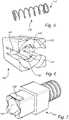
- Fig. 16shows a ferrule back body holder 440 (henceforth referred to as a back body holder 440) which is cylindrical in contrast to the rectangular back body holder 140, described with reference to Fig. 6 .
- the back body holder 440has arms 443 for engaging with the annular recess 124 of the ferrule back body 120.
- the back body holder 440also has an opening 441 with a geometry for interacting with the guide element 123 of the ferrule back body 120 for maintaining a certain orientation.
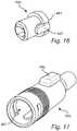
- Fig. 17shows a first housing member 450 (henceforth referred to as a rear connector housing 450).
- the rear hosing member 450has a passage 151 sized to allow the ferrule 110 and the ferrule back body 120 to pass through the rear connector housing 450.
- the passage 451is sized to prevent the biasing member 130 from passing through the passage 451.
- the rear connector housing 450has an external guide element 452 to keep track of the orientation of the fibre 320 mounted in the ferrule 110.
- Fig. 18shows a second housing member 460 (henceforth referred to as a front connector housing 460).
- a front connector housing 460Similarly to the connector housings 150 and 160, described with reference to Figs. 7 and 8 , the rear connector housing 450 and the front connector housing 460 are shaped to match each other so as to form a housing when attached to each other.
- the front connector housing 460has a passage 461 sized to allow the ferrule 110 to extend out of the housing.
- Fig. 19is a cross sectional view of a connector 500.
- the connector 500has been assembled from the assembly comprising the ferrule 110, the ferrule back body 120, the biasing member 130, the back body holder 440, the rear connector housing 450 and the front connector housing 460.
- the connector 500may be assembled using the same method 200 (described above with reference to Figs. 9-15 ) as the LC connector 370 except that the pieces employed have different shapes.
- the present connector 500has a cylindrical shape.
- the present connector 500allows the ferrule 110, the ferrule back body 120 and the back body holder 440 to piston along an axial direction relative to the housing.
- Fig. 20is a side view of an interconnection member 600 (or adaptor) for use with the connector 500 described with reference to Fig. 19 .
- the interconnection member 600is employed for connecting the ferrule 110 (and the optical fibre 320 therein) to a mating ferrule (and an end of an optical fibre arranged therein).
- the interconnection member 600comprises a body 610, an opening 620 in the body 610 for receiving the connector 500 (or for receiving the housing of the connector 500), a sealing element 630 for sealing the opening 620 of the interconnection member 600 around the connector 500 (or around the housing of the connector 500), and a passage 640 in the opening 620 of the interconnection member 600 for receiving the ferrule 110.
- the passage 640is a ceramic sleeve 640 provided with a ferrule guide 650 at the entrance of the passage 640 for guiding the ferrule 110 during insertion.
- the sealing element 630is provided in the form of a rubber ring 630.
- the interconnection member 600has a similar opening 620' on the opposite side for receiving another connector 500, such that the ferrules 110 (and the optical fibres within the ferrules 110) of the respective connectors 500 meet in the passage 640.
- the connectors 500may simply be pushed into the respective openings 620 and 620'.
- Fig. 21illustrates use of the interconnection member 600 described with reference to Fig. 20 for connecting two connectors 500 of the type described with reference to Fig. 19 . It will be appreciated that, in order to improve clarity in Fig. 21 , some of the components (e.g. ferrule back body 120 and back body holder 140) of the connectors 500 are not show therein.
- sealing elements 470have been arranged to seal the passage 451 of the rear connector housing 450 around the optical fibre 320 or around a protective coating 321 enclosing the fibre 320.
- an optical fibre 320may be provided in a cable comprising several layers enclosing the centrally arranged optical fibre 320.
- a 125um diameter fibre 320may be covered by a 250 um primary coating, a 900 um tight buffer, and a cable jacket, such that the cable has a diameter of 2-3 mm.
- the sealing elements 470may for example be rubber rings 470 held in place by crimps 480 or clamps.
- the sealing elements 630 of the interconnection member 600 and the sealing elements 470 of the connectors 500allow the interconnection member 600 and the connectors 500 to form a water resistant connection suitable for outdoor use.
- a connectionmay for example comply with an environmental sealing rating (or IP rating).
- IP ratingan environmental sealing rating
- the sealing element 470restrains the cable 321 to protect the ferrule 110 from being affected if the cable 321 is pulled.
- the connector 500allows the ferrule 110 to piston back and forth.
- the sealing element 470restrains the cable 321 from moving, the fibre 320 flexes (or bends) somewhat inside the connector 500 when the ferrule 110 pistons.
- connectors having other external shapes than those described abovemay also be assembled using assemblies and methods according to at least some embodiments.
- the ferrule 110may for example have a width W1 of 2.5 mm instead of 1.25 mm, and the connector obtained via the method 200 may for example be larger than a regular LC connector.
- connectors and assemblies according to at least some embodimentsmay for example comprise multiple ferrules for accommodating multiple optical fibres.
Landscapes
- Physics & Mathematics (AREA)
- General Physics & Mathematics (AREA)
- Optics & Photonics (AREA)
- Mechanical Coupling Of Light Guides (AREA)
Description
- The present disclosure generally relates to connectors for optical fibres, methods for assembling such connectors, and associated assemblies.
- Traditional telephony services have developed from use of analogue voice, to digital voice, to modem data, and to high speed digital subscriber lines. The traditional copper wires are now at the end of their lifespan as the cost for further increasing bandwidth capabilities is starting to outweigh any possible return. Copper wires are therefore being replaced by optical fibres which are able to provide much higher bandwidth than the copper wires.
- An optical fibre may be provided to a house by feeding the fibre through a duct leading to the house. The fibre may for example be fed through the duct by pushing or pulling the fibre through the duct. A commonly used method to feed fibres through ducts is to blow the fibre through the duct using compressed air. At the far side of the duct (for example inside a building to which data is to be delivered by the fibre), the fibre is then be terminated. The end of the fibre is usually placed in a ferrule which is then placed in some type of connector body so as to form a connector at the end of the fibre. When connecting two fibres to each other, the shape of the end faces of the fibres is important for ensuring that losses remain small. The end faces of the fibres may be polished at certain angles to reduce losses. Proper orientation of the fibre ends relative to each other may therefore be important for ensuring that losses remain small. The fibre ends may also be quite fragile. Termination of fibres may therefore require certain skill and may take quite some time to perform. Termination of the fibres in the field may therefore be a bottleneck when fibres are installed into homes.
- In order to reduce installation time, some fibres are delivered as preterminated fibres. In other words, a ferrule has already been mounted at the end of the fibre in the factory, and is passed though the duct together with the fibre. Although the ferrule has already been mounted, assembly of the rest of the connector may be quite complicated, for example if a certain orientation of the fibre has to be maintained (such as when the fibre has been polished at an angle). Moreover, an assembly from which the connector is assembled may include several quite small parts which have to be assembled in a specific manner to obtain the connector. Parts of the assembly (or even the connector itself once assembled) may be fragile or difficult to handle manually. The assembly may also be complicated and/or expensive to manufacture.
- An example of an optical connector suitable for field assembly is described in the US patent application with publication no.
US 2016/0047995 A1 . A kit comprising certain assembly jigs is employed to assemble a connector at a ferrule coupled to an optical fibre. Another example of prior art may be found inGB2468442 - However, it would be advantageous to provide new connectors, assemblies and/or methods for assembling connectors which address at least some of the abovementioned issues.
- The invention relates to an optical connector assembly according to claim 3 and a method of its assembling according to claim 1. Different embodiments are set out in the dependent claims.
- In what follows, example embodiments will be described in greater detail and with reference to the accompanying drawings, on which:
Fig. 1 shows a ferrule;Figs. 2-4 are different views of a ferrule back body;Fig. 5 shows a biasing member;Fig. 6 shows a ferrule back body holder for use in an LC connector;Fig. 7 shows a first housing member for use in an LC connector;Fig. 8 shows a second housing member for use in an LC connector;Fig. 9 is a flow chart of a method of assembling an LC connector using the components shown inFigs. 1-8 , according to an embodiment;Figs. 10-15 illustrate the respective steps of the method shown inFig. 9 ;Fig. 16 shows a ferrule back body holder for use in a connector adapted for outdoor use;Fig. 17 shows a first housing member for use in a connector adapted for outdoor use;Fig. 18 shows a second housing member for use in a connector adapted for outdoor use;Fig. 19 shows a connector for adapted outdoor use, according to an embodiment;Fig. 20 shows an interconnection member for use with the connector shown inFig. 19 ;Fig. 21 illustrates use of the interconnection member fromFig. 20 for connecting two connectors of the type shown inFig. 19 .- All the figures are schematic and generally only show parts which are necessary in order to elucidate the respective embodiments, whereas other parts may be omitted or merely suggested.
- An assembly will be described below with reference to
Figs. 1-8 , according to an embodiment. The assembly comprises aferrule 110, aferrule back body 120, abiasing member 130, and a ferruleback body holder 140. - The assembly further comprises a first housing member 150 (or first enclosing member) and a second housing member 160 (or second enclosing member) shaped to mach each other so as to form a housing when attached to each other. As described below, the pieces of the assembly may be shaped to fit together so as to form a connector. The
ferrule 110, theferrule back body 120, thebiasing member 130, and the ferruleback body holder 140 may together be regarded as a subassembly which may for example be sold or delivered together. By adding thefirst housing member 150 and thesecond housing member 160, an assembly may be formed from which a connector having a housing may be assembled. Fig. 1 is a perspective view of theferrule 110. Theferrule 110 has an opening 111 (or bore, or through hole) extending through theferrule 110 for accommodating an end portion of an optical fibre.- In the present embodiment, the
ferrule 110 has a cylindrical shape and theopening 111 extends along the center of theferrule 110 along its axis of symmetry. Theferrule 110 may be a high precision product for keeping losses low when connecting theferrule 110 to a mating ferrule housing another optical fibre. The position and diameter of theopening 111 may be important factors. Theopening 111 may for example have a diameter of 125.5 micrometers for accommodating a fibre with a diameter of 125 micrometers and may for example be located at the very center of theferrule 110. Theferrule 110 may for example be of a ceramic material. Fig. 2 is a perspective view of theferrule back body 120,Fig. 3 is a side view of theferrule back body 120, andFig. 4 is cross sectional view of theferrule back body 120 along the line A - A'. Theferrule back body 120 has anopening 121 for insertion of theferrule 110 along anaxial direction 122. Theferrule back body 120 has aguide element 123 which may also be referred to as akeyway 123.- In the present embodiment, the ferrule back
body 120 is cylindrical and theopening 121 extends along the center (or axis of symmetry) of the ferrule backbody 120. The ferrule backbody 120 may for example be made of metal or plastic material. - In the present embodiment, the
guide element 123 is arecess 123 extending in theaxial direction 122 along the exterior surface of the ferrule backbody 120. Such arecess 123 is easy to provide during manufacture of the ferrule backbody 120. Embodiments may also be envisaged in which theguide element 123 includes multiple recesses, and/or one or more protruding elements. - In the present embodiment, the ferrule back
body 120 has arecess 124 for fastening elements of the ferrule back body holder 140 (described below with reference toFig. 6 ) to engage with. Therecess 124 may for example be anannular recess 124 which extends all the way around the ferrule backbody 120. Althoughannular recesses 124 may be easier to provide during manufacture of the ferrule backbody 120, embodiments may also be envisaged in which the ferrule backbody 120 has other types of recesses, or slots, or grooves, to which the ferrule backbody holder 140 may attach, or a recess extending only partway around the ferrule backbody 120. - Example dimensions for the ferrule back
body 120 are given below. The person skilled in the art realizes that these dimensions merely serve as examples, and that other dimensions than those in the example may also be employed. - The ferrule back
body 120 may have a length L of 6 mm and a width W1 of 2 mm. Theopening 121 may extend through the entire ferrule backbody 120 along theaxial direction 122 and may have a width W2 of 1.25 mm for insertion of a ferrule of diameter 1.25 mm (or slightly less than 1.25 mm). Therecess 123 forming theguide element 123 may have a width W3 of 0.6 mm and a depth D1 of 0.2 mm. Theannular recess 124 may be arranged at (or close to) the middle of the ferrule backbody 120, it may have a width W4 of 1 mm and a depth D2 of 0.25 mm. Therecess 123 forming theguide element 123 may comprise one portion on each side of theannular recess 124. The ferrule backbody 120 may be tapered 125 at a front end at from which theferrule 110 is to extend when mounted in theopening 121 of the ferrule backbody 120. Fig. 5 is a perspective view of the biasingmember 130, exemplified herein by acoil spring 130 of metal (for example iron). The biasingmember 130 has apassage 131 sized to allow theferrule 110 and the ferrule backbody 120 to pass through the biasingmember 130. Thepassage 131 is sized to prevent the ferrule backbody 120 from passing through thepassage 131 when attached to the ferrule back body holder 140 (described below with reference toFig. 6 ). If the ferrule backbody 120 has a width W1 (or diameter) of 2 mm and the ferrule backbody holder 140 has a width (or diameter) of 3 mm, theopening 131 of the biasingmember 130 may for example be 2.1 mm wide.- The biasing member 130 (or coil spring 130) may for example be of similar length (when not compressed, i.e., when in its resting position) as the
ferrule 110. - Although metal coil springs 130 (or helical springs) are suitable as biasing
members 130 due to their reliability and low cost, any biasingmember 130 able to provide similar biasing, and having apassage 131 of similar shape as the passage of thecoil spring 130 may be employed instead of thecoil spring 130. Alternative biasingmembers 130 may for example be formed as annularly shaped pieces of suitable resilient materials (i.e., which is able to expand after being compressed, so as to provide a suitable biasing force) Fig. 6 is a perspective view of the ferrule back body holder 140 (or simply back body holder 140). Theback body holder 140 has anopening 141 adapted to receive at least a portion of the ferrule backbody 120 via movement of the ferrule backbody 120 relative to theback body holder 140 in theaxial direction 122. Theopening 141 of theback body holder 140 is shaped to engage with theguide element 123 of the ferrule backbody 120 for maintaining a certain orientation of the ferrule backbody 120 relative to theback body holder 140. In the present embodiment, aprotrusion 142 along an interior wall of theopening 141 is arranged to engage with theguide element 123 of the ferrule backbody 120 for maintaining the orientation during insertion of the ferrule backbody 120.- The
back body holder 140 hasfastening elements 143 for attaching the ferrule backbody holder 140 to the portion of the ferrule backbody 120 inserted into theopening 141. Thefastening elements 143 are exemplified herein by twoarms 143 arranged to engage with therecess 124 of the ferrule backbody 120 when the ferrule backbody 120 is inserted far enough into theopening 141 of theback body holder 140. Thefastening elements 143 and therecess 124 together form a convenient snap fit design. - In the present embodiment, the
back body holder 140 has a rectangular shape. Theback body holder 140 may for example be made of a plastic material. Theback body holder 140 may for example be formed (e.g. molded) in one piece rather than being assembled from multiple pieces. Fig. 7 is a perspective view of thefirst housing member 150 which will be referred to herein as arear connector housing 150. Therear connector housing 150 has apassage 151 sized to allow theferrule 110 and the ferrule backbody 120 to pass through therear connector housing 150. Thepassage 151 of therear connector housing 150 is sized to prevent the biasingmember 130 from passing through thepassage 151 of therear connector housing 150. Therear connector housing 150 may for example comprise a surface within thepassage 151 adapted to retain the biasingmember 130.- If for example the ferrule back
body 120 has a width W1 of 2 mm and the biasing member has a diameter (or width) of 2.5 mm, thepassage 151 of therear connector housing 150 may for example have a width of 2.3 mm. Fig. 8 is a perceptive view of thesecond housing member 160 which will be referred to herein as afront connector housing 160. Thefront connector housing 160 has anopening 161 for allowing theferrule 110 to extend out of the housing formed by the rear andfront connector housings - In the present embodiment, the rear and
front connector housings protrusions 152 positioned and shaped to matchopenings 162 in thefront connector housing 160. Thefront connector housing 160 comprises the same type ofpush button 163 as an LC connector (or Lucent connector). - In the present example, the
rear connector housing 150 and thefront connector housing 160 are shaped such that the housing has the same exterior shape as an LC connector (or Lucent connector). Embodiments may also be envisaged wherein therear connector housing 150 and thefront connector housing 160 are shaped such that the housing has the same exterior shape as another type of connector, such as a MU connector (or miniature unit). - The
front connector housing 150 and therear connection housing 160 may for example be made of a plastic material. Fig. 9 is a flow chart of amethod 200 of assembling an LC connector using the assembly described with reference toFigs. 1-8 , according to an embodiment. Themethod 200 will be described also with reference toFigs. 10-15 which illustrate the respective steps of themethod 200.- The
method 200 comprises providing 210 a ferrule assembly 310 (or ferrule subassembly) mounted at an end of anoptical fibre 320. Thisstep 210 is illustrated inFig. 10 . Theferrule assembly 310 comprises theferrule 110 and the ferrule backbody 120. Theferrule 110 is mounted in theopening 121 of the ferrule backbody 120. Theoptical fibre 320 extends through theferrule 110 along theaxial direction 122. And end face of theoptical fibre 320 is located at atip end 112 of theferrule 110. Theferrule assembly 310 may for example be assembled in a factory and brought to a location where a connector is to be assembled. - In the present embodiment, the
optical fibre 320 is provided in acable 321 comprising one or more protecting layers enclosing thefibre 320. - The end face of the
optical fibre 320 may for example be polished at an angle for reducing losses when connected to another optical fibre. The angle may for example be 4, 8 or 9 degrees relative to a plane orthogonal to theaxial direction 122. The polishing may for example be performed in a factory, but could alternatively be performed in the field. The polishing of the end face of thefibre 320 may be performed by polishing thetip end 112 of theferrule 110. Theannular recess 124 may be employed to hold theferrule assembly 310 at a fixed axial position during polishing. Theguide element 123 may be employed to hold theferrule assembly 310 at a certain rotational position (or orientation) around theaxis 122 during polishing, so that theguide element 123 may later be employed to keep track of the orientation of the polished end face (and of the fibre 320). - The
method 200 comprises passing 220 theferrule assembly 310 through atubular section 330 such that a portion of theoptical fibre 320 ends up in thetubular section 330. Thisstep 220 is illustrated inFig. 11 . - The
tubular section 330 may for example be a duct or tube of more or less any kind (such as a microduct, flexible tubing, or braided tubing). Theferrule assembly 310 may for example be passed through thetubular section 330 by blowing theferrule assembly 310 through the tubular section 330 (henceforth referred to as a duct 330). Theferrule assembly 310 may for example be passed through theduct 330 by pushing or pulling theferrule assembly 310 through theduct 330. If theferrule assembly 310 is pushed or pulled through theduct 330, this process may for example be assisted by causing a vacuum at the receiving end so as to suck theferrule assembly 310 through theduct 330. During blowing (or vacuum assisted pushing or pulling) of theferrule assembly 310 through theduct 330, theferrule assembly 310 may be equipped with a sealing ring (not shown inFig. 11 ) to improve the effect of the blowing (or of the vacuum). - The
method 200 comprises passing 230 theferrule assembly 310 through thepassage 151 of the rear connector housing 150 (or first housing member 150) until at least a portion of the ferrule backbody 120 protrudes out of thepassage 151 of therear connector housing 150 at afar side 340 of therear connector housing 150. Thisstep 230 is performed while a portion of theoptical fibre 320 remains inside theduct 330, and is illustrated inFig. 12 . The step of passing 230 theferrule assembly 310 through thepassage 151 of therear connector housing 150 may for example be performed by moving therear connector housing 150 in theaxial direction 122 while keeping the ferrule assembly for more less 310 fixed. - The
method 200 comprises passing 240 theferrule assembly 310 through thepassage 131 of the biasingmember 130 until at least a portion of the ferrule backbody 120 protrudes out of thepassage 131 at afar side 350 of the biasingmember 130. Thisstep 240 is performed while a portion of theoptical fibre 320 remains inside theduct 330. - The
method 200 comprises inserting 250 the protruding portion of the ferrule backbody 120 into theopening 141 of theback body holder 140. Thesteps Fig. 13 . - The
insertion 250 comprises moving theferrule assembly 310 relative to theback body holder 140 in theaxial direction 122 until at least a portion of the ferrule backbody 120 is located in theopening 141 of theback body holder 140. When the movement is initiated, theferrule assembly 131 is oriented such that theferrule 110 faces towards the opening 141 of theback body holder 140. Thetip end 121 of theferrule 110 therefore enters theopening 141 of theback body holder 140 before the ferrule backbody 120 enters thisopening 141. - The
insertion 250 also comprises maintaining, during the relative movement in theaxial direction 122, an orientation of the ferrule backbody 120 relative to theback body holder 140, determined by theguide element 123. In the present embodiment, theprotrusion 142 in theopening 141 of theback body holder 140 fits in the guide element 123 (which is arecess 123 extending in the axial direction 122). When the ferrule backbody 120 is inserted into theopening 141 of theback body holder 140, theprotrusion 142 slides along theguide element 123 and ensures that the ferrule assembly 310 (and the polished end face of the optical fibre 320) is properly oriented relative to theback body holder 140. - The
method 200 comprises attaching 260 theback body holder 140 to the portion of the ferrule backbody 120 located in theopening 141 of theback body holder 140. The size of theback body holder 140 thereby prevents theferrule assembly 310 from passing back through thepassage 131 of the biasingmember 130. Thisstep 260 is illustrated inFig. 14 . - The
back body holder 140 may be attached 260 to the ferrule backbody 120 via a snap fit design. In other words, a fastening element may snap into place when the ferrule backbody 120 is inserted a certain distance into theopening 141 of theback body holder 140. In the present embodiment,fastening elements 143 in the form of twoarms 143 snap into place in theannular recess 124 of the ferrule backbody 120, thereby attaching 260 theback body holder 140 to the ferrule backbody 120. - When the
back body holder 140 has been attached to the ferrule backbody 120, theferrule 110 extends out through a passage at the back of theopening 141 of theback body holder 140. This passage of theback body holder 140 is sized to prevent the biasingmember 130 from passing through theback body holder 140. Theback body holder 140 may for example comprise a surface 145 (shown inFig. 6 ) at theopening 141 adapted to retain the biasingmember 130. - If the
back body holder 140 would have been attached to the ferrule backbody 120 from above, it would have needed to be open at the bottom to allow thefibre 320 to enter theback body holder 140. As theback body holder 140 is instead attached from the front of the ferrule assembly 310 (via relative movement in the axial direction 122) theback body holder 140 may extend all the way around the ferrule back body 120 (i.e. a full rotation around the axis 122). Theback body holder 140 therefore better protects thefibre 320 from side pulls or other potential deformations which could harm thefibre 320 and/or increase losses in thefibre 320. - The
method 200 comprises attaching 270 the front connector housing 160 (or second housing member 160) to therear connector housing 150 to form a housing enclosing the biasingmember 130, the ferrule backbody 120 and theback body holder 140. Thisstep 270 is illustrated inFig. 15 . - When assembled, the assembly described with reference to
Figs 1-8 form anLC connector 370. The housing formed by therear connector housing 150 and thefront connector housing 160 has the same exterior shape as a regular LC connector but has an interior shape specifically adapted to house the other components of the assembly. - The
ferrule 110 extends out of theopening 161 of thefront connector housing 161. The end face of theoptical fibre 320 is therefore exposed, and can for example be cleaned. Thespring 130 biases (or pushes) the ferrule assembly 310 (and theback body holder 140 attached thereto) forward towards thefront connector housing 160 such that theback body holder 140 rests against (or is in abutment to) an interior surface of thefront connector housing 160. Thespring 130 allows the ferrule assembly 310 (and theback body holder 140 attached thereto) to piston backwards within the housing along theaxial direction 122 if subjected to a force. The bias provided by thespring 130 allows theferrule 110 to be placed tightly in contact with another ferrule, without being damaged in case of a slight mismatch. This type of spring basedferrule 110 is sometimes referred to as a floating ferrule. When in its resting position, the ferrule may for example extend 2 mm out of theopening 161 of thefront connector housing 160. - The
front connector housing 160 may for example have an interior shape, and/or theback body holder 140 may for example have an exterior shape, which only allows the ferrule assembly 310 (to which theback body holder 140 is attached) to have a particular orientation within the housing. This facilitates correct orientation of theferrule 110 with a mating ferrule when theconnector 370 is employed to connect theoptical fibre 320 with another optical fibre. - The ferrule back
body 120 described with reference toFig. 2 has a shape (aguide element 123 in the form of arecess 123 extending along axial direction and anannular recess 124 for attaching the back body holder 140) which makes it easy to manufacture. As the ferrule backbody 120 has no protruding portions (except the ferrule 110) the risk of theferrule assembly 310 getting stuck in theduct 330 due to splices in theduct 330 or dirt in theduct 330 is reduced. The shape of the ferrule backbody 120 also allows theferrule assembly 310 to be made small enough to be blown (or pushed or pulled) throughnarrow ducts 330. A widest portion of the ferrule backbody 120 may for example be no more than a factor 2 or 3 times as wide as the widest portion of theferrule 110. The ferrule back body may for example be no more than 2, 2.1, 2.2, 2.5 or 3 mm wide. A ferrule mounted at a 1.25 micrometer diameter optical fibre may therefore be blown through a microduct of having a diameter of 3 mm. - Since the
spring 130 does not need to be fed through theduct 330, there is no need to make thespring 130 small enough to fit into theduct 330. Thespring 130 may therefore be made as large as needed to obtain the desired biasing force and/or durability. Figs. 16-21 show parts of an assembly. In contrast to the assembly described with reference toFigs. 1-15 , the assembly described with reference toFigs 16-21 is better suited for outdoor use.Fig. 16 shows a ferrule back body holder 440 (henceforth referred to as a back body holder 440) which is cylindrical in contrast to the rectangularback body holder 140, described with reference toFig. 6 . Similarly to theback body holder 140, described with reference toFig. 6 , theback body holder 440 hasarms 443 for engaging with theannular recess 124 of the ferrule backbody 120. Theback body holder 440 also has anopening 441 with a geometry for interacting with theguide element 123 of the ferrule backbody 120 for maintaining a certain orientation.Fig. 17 shows a first housing member 450 (henceforth referred to as a rear connector housing 450). Similarly to therear housing member 150, described with reference toFig. 7 , therear hosing member 450 has apassage 151 sized to allow theferrule 110 and the ferrule backbody 120 to pass through therear connector housing 450. Thepassage 451 is sized to prevent the biasingmember 130 from passing through thepassage 451. Therear connector housing 450 has anexternal guide element 452 to keep track of the orientation of thefibre 320 mounted in theferrule 110.Fig. 18 shows a second housing member 460 (henceforth referred to as a front connector housing 460). Similarly to theconnector housings Figs. 7 and8 , therear connector housing 450 and thefront connector housing 460 are shaped to match each other so as to form a housing when attached to each other. Thefront connector housing 460 has apassage 461 sized to allow theferrule 110 to extend out of the housing.Fig. 19 is a cross sectional view of aconnector 500. Theconnector 500 has been assembled from the assembly comprising theferrule 110, the ferrule backbody 120, the biasingmember 130, theback body holder 440, therear connector housing 450 and thefront connector housing 460. It will be appreciated that theconnector 500 may be assembled using the same method 200 (described above with reference toFigs. 9-15 ) as theLC connector 370 except that the pieces employed have different shapes. In contrast to theLC connector 370, thepresent connector 500 has a cylindrical shape. Similarly to theLC connector 370, thepresent connector 500 allows theferrule 110, the ferrule backbody 120 and theback body holder 440 to piston along an axial direction relative to the housing.Fig. 20 is a side view of an interconnection member 600 (or adaptor) for use with theconnector 500 described with reference toFig. 19 . Theinterconnection member 600 is employed for connecting the ferrule 110 (and theoptical fibre 320 therein) to a mating ferrule (and an end of an optical fibre arranged therein). Theinterconnection member 600 comprises abody 610, anopening 620 in thebody 610 for receiving the connector 500 (or for receiving the housing of the connector 500), a sealingelement 630 for sealing theopening 620 of theinterconnection member 600 around the connector 500 (or around the housing of the connector 500), and apassage 640 in theopening 620 of theinterconnection member 600 for receiving theferrule 110.- In the present embodiment, the
passage 640 is aceramic sleeve 640 provided with aferrule guide 650 at the entrance of thepassage 640 for guiding theferrule 110 during insertion. The sealingelement 630 is provided in the form of arubber ring 630. - The
interconnection member 600 has a similar opening 620' on the opposite side for receiving anotherconnector 500, such that the ferrules 110 (and the optical fibres within the ferrules 110) of therespective connectors 500 meet in thepassage 640. Theconnectors 500 may simply be pushed into therespective openings 620 and 620'. Fig. 21 illustrates use of theinterconnection member 600 described with reference toFig. 20 for connecting twoconnectors 500 of the type described with reference toFig. 19 . It will be appreciated that, in order to improve clarity inFig. 21 , some of the components (e.g. ferrule backbody 120 and back body holder 140) of theconnectors 500 are not show therein.- In order to make the
connectors 500 water resistant (and therefore suitable for outdoor use), sealingelements 470 have been arranged to seal thepassage 451 of therear connector housing 450 around theoptical fibre 320 or around aprotective coating 321 enclosing thefibre 320. As is well-known to the person skilled in the art, anoptical fibre 320 may be provided in a cable comprising several layers enclosing the centrally arrangedoptical fibre 320. For example, a125um diameter fibre 320 may be covered by a 250 um primary coating, a 900 um tight buffer, and a cable jacket, such that the cable has a diameter of 2-3 mm. The sealingelements 470 may for example be rubber rings 470 held in place bycrimps 480 or clamps. - The sealing
elements 630 of theinterconnection member 600 and the sealingelements 470 of theconnectors 500 allow theinterconnection member 600 and theconnectors 500 to form a water resistant connection suitable for outdoor use. Such a connection may for example comply with an environmental sealing rating (or IP rating). In other words, due to the environmental seal provided by theinterconnection member 600 and theconnectors 500, there may be no need for additional sealing layers (which may be costly and/or which may take up a lot of space) for protecting the interior of theconnectors 500 and theoptical fibres 320 from environmental conditions experienced outdoors. - In addition to preventing water to enter the
connector 500, the sealingelement 470 restrains thecable 321 to protect theferrule 110 from being affected if thecable 321 is pulled. - As described above, the
connector 500 allows theferrule 110 to piston back and forth. As the sealingelement 470 restrains thecable 321 from moving, thefibre 320 flexes (or bends) somewhat inside theconnector 500 when theferrule 110 pistons. - The person skilled in the art realizes that the present invention is by no means limited to the preferred embodiments described above. On the contrary, many modifications and variations are possible within the scope of the appended claims. For example, although only a few example connectors have been described in detail above, it will be appreciated that connectors having other external shapes than those described above may also be assembled using assemblies and methods according to at least some embodiments. The
ferrule 110 may for example have a width W1 of 2.5 mm instead of 1.25 mm, and the connector obtained via themethod 200 may for example be larger than a regular LC connector. It will also be appreciated that connectors and assemblies according to at least some embodiments may for example comprise multiple ferrules for accommodating multiple optical fibres. - In the claims, the word "comprising" does not exclude other elements or steps, and the indefinite article "a" or "an" does not exclude a plurality.
Claims (11)
- A method (200) for assembling an optical connector assembly, the method comprising:providing (210) a ferrule assembly (310) mounted at an end of an optical fibre (320), the ferrule assembly comprising a ferrule (110) and a ferrule back body (120), wherein the ferrule is mounted in an opening (121) of the ferrule back body, wherein the optical fibre extends through the ferrule along an axial direction (122) of the ferrule assembly, and wherein the ferrule back body has a guide element (123);passing (220) the ferrule assembly (310) through a tubular section (330) such that a portion of the optical fibre ends up in the tubular section;passing (240) the ferrule assembly through a passage (131) of a biasing member (130), while maintaining a portion of the optical fibre inside the tubular section, until at least a portion of the ferrule back body protrudes out of the passage at a far side (350) of the biasing member;inserting (250) the at least a protruding portion of the ferrule back body into an opening (141, 441) of a ferrule back body holder (140, 440), wherein the insertion comprises:moving the ferrule assembly (310) relative to the ferrule back body holder (140, 440) in the axial direction until at least a portion of the ferrule back body (120) is located in the opening of the ferrule back body holder; andmaintaining, during the relative movement in the axial direction, an orientation of the ferrule back body relative to the ferrule back body holder determined by the guide element (123); andattaching (260) the ferrule back body holder (140, 440) to the at least a portion of the ferrule back body located in the opening of the ferrule back body holder, the ferrule back body holder thereby preventing the ferrule assembly (310) from passing back through the passage of the biasing memberwherein the method further comprises, prior to passing the ferrule assembly through the passage of the biasing member (130):passing (230) the ferrule assembly through a passage (151, 451) of a first housing member (150, 450), while maintaining a portion of the optical fibre inside the tubular section (330), until at least a portion of the ferrule back body (120) protrudes out of the passage of the first housing member at a far side (340) of the first housing member, wherein the passage of the first housing member is sized to prevent the biasing member (130) from passing through the passage of the first housing member,and, after attaching the ferrule back body holder (140, 440): attaching (270) a second housing member (160, 460) to the first housing member (150, 450) to form a housing enclosing the biasing member, the ferrule back body and the ferrule back body holder, the second housing member having an opening (161, 461) for allowing contact between the optical fibre and another optical fibre.
- The method of claim 1, wherein attaching the ferrule back body holder (140, 440) to the at least a portion of the ferrule back body (120) located in the opening of the ferrule back body holder comprises:
inserting the at least a protruding portion of the ferrule back body a certain distance into the opening of the ferrule back body holder such that a fastening element (143) snaps into place. - An optical connector assembly comprising:a ferrule (110) having an opening (111) extending through the ferrule for accommodating an end portion of an optical fibre (320);a ferrule back body (120) having an opening (121) for insertion of the ferrule along an axial direction (122), wherein the ferrule back body has a guide element (123);a biasing member (130) having a passage (131) sized to allow the ferrule and the ferrule back body to pass through the biasing member; anda ferrule back body holder (140, 440) having an opening (141, 441) adapted to receive at least a portion of the ferrule back body via movement of the ferrule back body relative to the ferrule back body holder in the axial direction,wherein the opening of the ferrule back body holder is shaped to engage with the guide element for maintaining a certain orientation of the ferrule back body relative to the ferrule back body holder, wherein the ferrule back body holder has a fastening element (143, 443) for attaching the ferrule back body holder to the at least a portion of the ferrule back body, and wherein said passage is sized to prevent the ferrule back body from passing through said passage when attached to the ferrule back body holder,wherein the optical connector assembly further comprises:a first housing member (150, 450) having a passage (151, 451) sized to allow the ferrule (110) and the ferrule back body (120) to pass through the first housing member, wherein the passage of the first housing member is sized to prevent the biasing member (130) from passing through the passage of the first housing member, anda second housing member (160, 460), wherein the first and second housing members are shaped to match each other so as to form a housing when attached to each other.
- The optical connector assembly of claim 3, wherein the guide element (123) extends in the axial direction along an exterior surface of the ferrule back body (120).
- The optical connector assembly of any of claims 3-4, wherein the guide element (123) is a recess.
- The optical connector assembly of any of claims 3-5, wherein the ferrule back body (120) has a recess (124) with which the fastening element (143, 443) of the ferrule back body holder (140, 440) is adapted to engage.
- The optical connector assembly of claim 6, wherein the recess (124) of the ferrule back body (120) is an annular recess.
- The optical connector assembly of any of claims 3-7, wherein the ferrule (110) is mounted in the opening of the ferrule back body (120), the optical connector assembly comprising:
an end portion of an optical fibre (320) accommodated in the opening of the ferrule, wherein an end face of the optical fibre has been polished at an angle. - The optical connector assembly of any one of claims 3-8, wherein the first (150, 450) and second (160, 460) housing members are shaped such that the housing has the same exterior shape as the housing of an LC connector or an MU connector.
- The optical connector assembly of any one of claims 3-9, further comprising a sealing element (470) for sealing the passage of the first housing member (150, 450) around the optical fibre, or around a protective coating enclosing the optical fibre.
- The optical connector assembly of any of any one of claims 3-10, wherein the second housing member (160, 460) has an opening (461) for allowing the ferrule 2. (110) to extend out of said housing, the optical connector assembly further comprising:
an interconnection member (600) for connecting the optical fibre to another optical fibre, the interconnection member comprising:an opening (620) for receiving the housing;a sealing element (630) for sealing the opening of the interconnection member around the housing; anda passage (640) in the opening of the interconnection member for receiving the ferrule.
Priority Applications (4)
| Application Number | Priority Date | Filing Date | Title |
|---|---|---|---|
| EP16190263.0AEP3299858B1 (en) | 2016-09-23 | 2016-09-23 | Method of assembling a fibre connector |
| EP22176151.3AEP4086677A1 (en) | 2016-09-23 | 2016-09-23 | Ferrule assembly |
| US16/335,165US10890721B2 (en) | 2016-09-23 | 2017-09-21 | Method of assembling a fibre connector |
| PCT/EP2017/073931WO2018055045A1 (en) | 2016-09-23 | 2017-09-21 | Method of assembling a fibre connector |
Applications Claiming Priority (1)
| Application Number | Priority Date | Filing Date | Title |
|---|---|---|---|
| EP16190263.0AEP3299858B1 (en) | 2016-09-23 | 2016-09-23 | Method of assembling a fibre connector |
Related Child Applications (1)
| Application Number | Title | Priority Date | Filing Date |
|---|---|---|---|
| EP22176151.3ADivisionEP4086677A1 (en) | 2016-09-23 | 2016-09-23 | Ferrule assembly |
Publications (2)
| Publication Number | Publication Date |
|---|---|
| EP3299858A1 EP3299858A1 (en) | 2018-03-28 |
| EP3299858B1true EP3299858B1 (en) | 2022-06-01 |
Family
ID=56990307
Family Applications (2)
| Application Number | Title | Priority Date | Filing Date |
|---|---|---|---|
| EP16190263.0AActiveEP3299858B1 (en) | 2016-09-23 | 2016-09-23 | Method of assembling a fibre connector |
| EP22176151.3APendingEP4086677A1 (en) | 2016-09-23 | 2016-09-23 | Ferrule assembly |
Family Applications After (1)
| Application Number | Title | Priority Date | Filing Date |
|---|---|---|---|
| EP22176151.3APendingEP4086677A1 (en) | 2016-09-23 | 2016-09-23 | Ferrule assembly |
Country Status (3)
| Country | Link |
|---|---|
| US (1) | US10890721B2 (en) |
| EP (2) | EP3299858B1 (en) |
| WO (1) | WO2018055045A1 (en) |
Families Citing this family (3)
| Publication number | Priority date | Publication date | Assignee | Title |
|---|---|---|---|---|
| MX2021008412A (en)* | 2019-01-10 | 2021-10-13 | Ppc Broadband Inc | LINEAR MEMBERS WITH ANNULAR AND AXIAL SLOTS. |
| US12386124B2 (en)* | 2022-11-30 | 2025-08-12 | Mellanox Technologies, Ltd. | Device for holding a plurality of ferrules against a respective plurality of receptacles |
| WO2025163322A1 (en) | 2024-02-01 | 2025-08-07 | Ridgemount Technologies Limited | Fibre optic connector, kits of parts and methods of using the same |
Family Cites Families (17)
| Publication number | Priority date | Publication date | Assignee | Title |
|---|---|---|---|---|
| US4762389A (en)* | 1984-03-30 | 1988-08-09 | Nec Corporation | Optical fiber connector |
| EP1092997A1 (en) | 1994-06-22 | 2001-04-18 | The Whitaker Corporation | Optical fiber connector having enhanced assembly means |
| JP2003207687A (en)* | 2002-01-16 | 2003-07-25 | Seiko Instruments Inc | Ferrule and its manufacturing method and optical connector plug |
| US7003208B2 (en)* | 2003-06-03 | 2006-02-21 | Fujikura Ltd. | Optical fiber connecting tool, connector holder, connector holder equipped optical connector, and tool equipped optical connector |
| US7178988B2 (en)* | 2003-07-15 | 2007-02-20 | Seikoh Giken Co., Ltd. | Optical connector plug and method for assembling same |
| US7104702B2 (en)* | 2004-03-24 | 2006-09-12 | Corning Cable Systems Llc | Field installable optical fiber connector |
| US20050238292A1 (en)* | 2004-03-24 | 2005-10-27 | Barnes Brandon A | Field installable optical fiber connector having plastic splice holder and metal ferrule holder |
| US7204644B2 (en)* | 2004-03-24 | 2007-04-17 | Corning Cable Systems Llc | Field installable optical fiber connector |
| US20060115219A1 (en)* | 2004-11-29 | 2006-06-01 | Mudd Ronald L | Optical fiber connector |
| GB2468442B (en)* | 2007-05-04 | 2011-01-19 | Miniflex Ltd | Method of installing a push/pull type optical fibre connector |
| EP2012153A1 (en) | 2007-07-06 | 2009-01-07 | Ridgemount Technologies Limited | Optical fibre ferrule assembly |
| US7513695B1 (en) | 2007-10-09 | 2009-04-07 | Protai Photonic Co., Ltd. | Small form factor, field-installable optical fiber connector |
| US8858090B2 (en)* | 2012-06-05 | 2014-10-14 | Corning Cable Systems Llc | Ferrule holders with an integral lead-in tube employed in fiber optic connector assemblies, and related components, connectors, and methods |
| US9297976B2 (en)* | 2012-11-14 | 2016-03-29 | Clearfield, Inc. | Optical fiber connector |
| CN106716202B (en) | 2014-08-06 | 2019-04-19 | 普睿司曼股份公司 | Fiber optic connector assembly |
| US9383527B2 (en) | 2014-08-13 | 2016-07-05 | Rolling River, LLC | Optical connector suitable for field assembly |
| WO2016061795A1 (en) | 2014-10-23 | 2016-04-28 | 深圳日海通讯技术股份有限公司 | Sc-type pre-terminated connector |
- 2016
- 2016-09-23EPEP16190263.0Apatent/EP3299858B1/enactiveActive
- 2016-09-23EPEP22176151.3Apatent/EP4086677A1/enactivePending
- 2017
- 2017-09-21USUS16/335,165patent/US10890721B2/enactiveActive
- 2017-09-21WOPCT/EP2017/073931patent/WO2018055045A1/ennot_activeCeased
Also Published As
| Publication number | Publication date |
|---|---|
| US20190278027A1 (en) | 2019-09-12 |
| WO2018055045A1 (en) | 2018-03-29 |
| US10890721B2 (en) | 2021-01-12 |
| EP4086677A1 (en) | 2022-11-09 |
| EP3299858A1 (en) | 2018-03-28 |
Similar Documents
| Publication | Publication Date | Title |
|---|---|---|
| US12092878B2 (en) | Fiber optic connectors having a keying structure and methods of making the same | |
| US11487064B2 (en) | Fiber optic connectors having a ferrule insertion stop | |
| CN102439502B (en) | Fiber optic connector and method for assembling | |
| CN100501473C (en) | On-site installable optical fiber connector | |
| US6918704B2 (en) | Tunable fiber optic connector | |
| JP4524277B2 (en) | Durable fiber optic connector assembly | |
| US8439577B2 (en) | Optical fibre connector | |
| US20140079356A1 (en) | Field terminable st format optical fiber connector | |
| US20130051734A1 (en) | Optical fiber connector | |
| CN102414593A (en) | Collar body for field terminable optical connector | |
| CN202453542U (en) | Optical fiber connector | |
| US11221456B2 (en) | Protective tube for micro-duct installation of fiber optic cable | |
| EP3299858B1 (en) | Method of assembling a fibre connector | |
| CN202472042U (en) | Optical fiber connector | |
| US11815723B2 (en) | Optical connection structure, optical connector, and optical connecting method | |
| US20060153502A1 (en) | Universal adapter for fiber optic connectors | |
| US12019281B2 (en) | Sealed optical cable assemblies and methods of fabricating the same | |
| JP2021157034A (en) | Metal-pipe sheathed optical fiber cable with optical connector, and method for manufacturing metal-pipe sheathed optical fiber cable with optical connector |
Legal Events
| Date | Code | Title | Description |
|---|---|---|---|
| PUAI | Public reference made under article 153(3) epc to a published international application that has entered the european phase | Free format text:ORIGINAL CODE: 0009012 | |
| STAA | Information on the status of an ep patent application or granted ep patent | Free format text:STATUS: THE APPLICATION HAS BEEN PUBLISHED | |
| AK | Designated contracting states | Kind code of ref document:A1 Designated state(s):AL AT BE BG CH CY CZ DE DK EE ES FI FR GB GR HR HU IE IS IT LI LT LU LV MC MK MT NL NO PL PT RO RS SE SI SK SM TR | |
| AX | Request for extension of the european patent | Extension state:BA ME | |
| STAA | Information on the status of an ep patent application or granted ep patent | Free format text:STATUS: REQUEST FOR EXAMINATION WAS MADE | |
| 17P | Request for examination filed | Effective date:20180928 | |
| RBV | Designated contracting states (corrected) | Designated state(s):AL AT BE BG CH CY CZ DE DK EE ES FI FR GB GR HR HU IE IS IT LI LT LU LV MC MK MT NL NO PL PT RO RS SE SI SK SM TR | |
| REG | Reference to a national code | Ref country code:DE Ref legal event code:R079 Ref document number:602016072478 Country of ref document:DE Free format text:PREVIOUS MAIN CLASS: G02B0006380000 Ipc:G02B0006440000 | |
| GRAP | Despatch of communication of intention to grant a patent | Free format text:ORIGINAL CODE: EPIDOSNIGR1 | |
| STAA | Information on the status of an ep patent application or granted ep patent | Free format text:STATUS: GRANT OF PATENT IS INTENDED | |
| RIC1 | Information provided on ipc code assigned before grant | Ipc:G02B 6/38 20060101ALI20211112BHEP Ipc:G02B 6/44 20060101AFI20211112BHEP | |
| INTG | Intention to grant announced | Effective date:20211222 | |
| GRAS | Grant fee paid | Free format text:ORIGINAL CODE: EPIDOSNIGR3 | |
| GRAA | (expected) grant | Free format text:ORIGINAL CODE: 0009210 | |
| STAA | Information on the status of an ep patent application or granted ep patent | Free format text:STATUS: THE PATENT HAS BEEN GRANTED | |
| AK | Designated contracting states | Kind code of ref document:B1 Designated state(s):AL AT BE BG CH CY CZ DE DK EE ES FI FR GB GR HR HU IE IS IT LI LT LU LV MC MK MT NL NO PL PT RO RS SE SI SK SM TR | |
| REG | Reference to a national code | Ref country code:GB Ref legal event code:FG4D | |
| REG | Reference to a national code | Ref country code:AT Ref legal event code:REF Ref document number:1495786 Country of ref document:AT Kind code of ref document:T Effective date:20220615 Ref country code:CH Ref legal event code:EP Ref country code:DE Ref legal event code:R096 Ref document number:602016072478 Country of ref document:DE | |
| REG | Reference to a national code | Ref country code:IE Ref legal event code:FG4D | |
| REG | Reference to a national code | Ref country code:FI Ref legal event code:FGE | |
| REG | Reference to a national code | Ref country code:NO Ref legal event code:T2 Effective date:20220601 | |
| REG | Reference to a national code | Ref country code:SE Ref legal event code:TRGR | |
| REG | Reference to a national code | Ref country code:LT Ref legal event code:MG9D | |
| REG | Reference to a national code | Ref country code:NL Ref legal event code:MP Effective date:20220601 | |
| PG25 | Lapsed in a contracting state [announced via postgrant information from national office to epo] | Ref country code:LT Free format text:LAPSE BECAUSE OF FAILURE TO SUBMIT A TRANSLATION OF THE DESCRIPTION OR TO PAY THE FEE WITHIN THE PRESCRIBED TIME-LIMIT Effective date:20220601 Ref country code:HR Free format text:LAPSE BECAUSE OF FAILURE TO SUBMIT A TRANSLATION OF THE DESCRIPTION OR TO PAY THE FEE WITHIN THE PRESCRIBED TIME-LIMIT Effective date:20220601 Ref country code:GR Free format text:LAPSE BECAUSE OF FAILURE TO SUBMIT A TRANSLATION OF THE DESCRIPTION OR TO PAY THE FEE WITHIN THE PRESCRIBED TIME-LIMIT Effective date:20220902 Ref country code:ES Free format text:LAPSE BECAUSE OF FAILURE TO SUBMIT A TRANSLATION OF THE DESCRIPTION OR TO PAY THE FEE WITHIN THE PRESCRIBED TIME-LIMIT Effective date:20220601 Ref country code:BG Free format text:LAPSE BECAUSE OF FAILURE TO SUBMIT A TRANSLATION OF THE DESCRIPTION OR TO PAY THE FEE WITHIN THE PRESCRIBED TIME-LIMIT Effective date:20220901 | |
| REG | Reference to a national code | Ref country code:AT Ref legal event code:MK05 Ref document number:1495786 Country of ref document:AT Kind code of ref document:T Effective date:20220601 | |
| PG25 | Lapsed in a contracting state [announced via postgrant information from national office to epo] | Ref country code:RS Free format text:LAPSE BECAUSE OF FAILURE TO SUBMIT A TRANSLATION OF THE DESCRIPTION OR TO PAY THE FEE WITHIN THE PRESCRIBED TIME-LIMIT Effective date:20220601 Ref country code:PL Free format text:LAPSE BECAUSE OF FAILURE TO SUBMIT A TRANSLATION OF THE DESCRIPTION OR TO PAY THE FEE WITHIN THE PRESCRIBED TIME-LIMIT Effective date:20220601 Ref country code:LV Free format text:LAPSE BECAUSE OF FAILURE TO SUBMIT A TRANSLATION OF THE DESCRIPTION OR TO PAY THE FEE WITHIN THE PRESCRIBED TIME-LIMIT Effective date:20220601 | |
| PG25 | Lapsed in a contracting state [announced via postgrant information from national office to epo] | Ref country code:NL Free format text:LAPSE BECAUSE OF FAILURE TO SUBMIT A TRANSLATION OF THE DESCRIPTION OR TO PAY THE FEE WITHIN THE PRESCRIBED TIME-LIMIT Effective date:20220601 | |
| PG25 | Lapsed in a contracting state [announced via postgrant information from national office to epo] | Ref country code:SM Free format text:LAPSE BECAUSE OF FAILURE TO SUBMIT A TRANSLATION OF THE DESCRIPTION OR TO PAY THE FEE WITHIN THE PRESCRIBED TIME-LIMIT Effective date:20220601 Ref country code:SK Free format text:LAPSE BECAUSE OF FAILURE TO SUBMIT A TRANSLATION OF THE DESCRIPTION OR TO PAY THE FEE WITHIN THE PRESCRIBED TIME-LIMIT Effective date:20220601 Ref country code:RO Free format text:LAPSE BECAUSE OF FAILURE TO SUBMIT A TRANSLATION OF THE DESCRIPTION OR TO PAY THE FEE WITHIN THE PRESCRIBED TIME-LIMIT Effective date:20220601 Ref country code:PT Free format text:LAPSE BECAUSE OF FAILURE TO SUBMIT A TRANSLATION OF THE DESCRIPTION OR TO PAY THE FEE WITHIN THE PRESCRIBED TIME-LIMIT Effective date:20221003 Ref country code:EE Free format text:LAPSE BECAUSE OF FAILURE TO SUBMIT A TRANSLATION OF THE DESCRIPTION OR TO PAY THE FEE WITHIN THE PRESCRIBED TIME-LIMIT Effective date:20220601 Ref country code:CZ Free format text:LAPSE BECAUSE OF FAILURE TO SUBMIT A TRANSLATION OF THE DESCRIPTION OR TO PAY THE FEE WITHIN THE PRESCRIBED TIME-LIMIT Effective date:20220601 Ref country code:AT Free format text:LAPSE BECAUSE OF FAILURE TO SUBMIT A TRANSLATION OF THE DESCRIPTION OR TO PAY THE FEE WITHIN THE PRESCRIBED TIME-LIMIT Effective date:20220601 | |
| PG25 | Lapsed in a contracting state [announced via postgrant information from national office to epo] | Ref country code:IS Free format text:LAPSE BECAUSE OF FAILURE TO SUBMIT A TRANSLATION OF THE DESCRIPTION OR TO PAY THE FEE WITHIN THE PRESCRIBED TIME-LIMIT Effective date:20221001 | |
| REG | Reference to a national code | Ref country code:DE Ref legal event code:R097 Ref document number:602016072478 Country of ref document:DE | |
| PG25 | Lapsed in a contracting state [announced via postgrant information from national office to epo] | Ref country code:AL Free format text:LAPSE BECAUSE OF FAILURE TO SUBMIT A TRANSLATION OF THE DESCRIPTION OR TO PAY THE FEE WITHIN THE PRESCRIBED TIME-LIMIT Effective date:20220601 | |
| PLBE | No opposition filed within time limit | Free format text:ORIGINAL CODE: 0009261 | |
| STAA | Information on the status of an ep patent application or granted ep patent | Free format text:STATUS: NO OPPOSITION FILED WITHIN TIME LIMIT | |
| PG25 | Lapsed in a contracting state [announced via postgrant information from national office to epo] | Ref country code:MC Free format text:LAPSE BECAUSE OF FAILURE TO SUBMIT A TRANSLATION OF THE DESCRIPTION OR TO PAY THE FEE WITHIN THE PRESCRIBED TIME-LIMIT Effective date:20220601 Ref country code:DK Free format text:LAPSE BECAUSE OF FAILURE TO SUBMIT A TRANSLATION OF THE DESCRIPTION OR TO PAY THE FEE WITHIN THE PRESCRIBED TIME-LIMIT Effective date:20220601 | |
| REG | Reference to a national code | Ref country code:CH Ref legal event code:PL | |
| 26N | No opposition filed | Effective date:20230302 | |
| REG | Reference to a national code | Ref country code:BE Ref legal event code:MM Effective date:20220930 | |
| PG25 | Lapsed in a contracting state [announced via postgrant information from national office to epo] | Ref country code:SI Free format text:LAPSE BECAUSE OF FAILURE TO SUBMIT A TRANSLATION OF THE DESCRIPTION OR TO PAY THE FEE WITHIN THE PRESCRIBED TIME-LIMIT Effective date:20220601 | |
| P01 | Opt-out of the competence of the unified patent court (upc) registered | Effective date:20230421 | |
| PG25 | Lapsed in a contracting state [announced via postgrant information from national office to epo] | Ref country code:LU Free format text:LAPSE BECAUSE OF NON-PAYMENT OF DUE FEES Effective date:20220923 | |
| PG25 | Lapsed in a contracting state [announced via postgrant information from national office to epo] | Ref country code:LI Free format text:LAPSE BECAUSE OF NON-PAYMENT OF DUE FEES Effective date:20220930 Ref country code:FR Free format text:LAPSE BECAUSE OF NON-PAYMENT OF DUE FEES Effective date:20220930 Ref country code:CH Free format text:LAPSE BECAUSE OF NON-PAYMENT OF DUE FEES Effective date:20220930 | |
| PG25 | Lapsed in a contracting state [announced via postgrant information from national office to epo] | Ref country code:BE Free format text:LAPSE BECAUSE OF NON-PAYMENT OF DUE FEES Effective date:20220930 | |
| PG25 | Lapsed in a contracting state [announced via postgrant information from national office to epo] | Ref country code:IT Free format text:LAPSE BECAUSE OF FAILURE TO SUBMIT A TRANSLATION OF THE DESCRIPTION OR TO PAY THE FEE WITHIN THE PRESCRIBED TIME-LIMIT Effective date:20220601 | |
| PG25 | Lapsed in a contracting state [announced via postgrant information from national office to epo] | Ref country code:HU Free format text:LAPSE BECAUSE OF FAILURE TO SUBMIT A TRANSLATION OF THE DESCRIPTION OR TO PAY THE FEE WITHIN THE PRESCRIBED TIME-LIMIT; INVALID AB INITIO Effective date:20160923 | |
| PG25 | Lapsed in a contracting state [announced via postgrant information from national office to epo] | Ref country code:CY Free format text:LAPSE BECAUSE OF FAILURE TO SUBMIT A TRANSLATION OF THE DESCRIPTION OR TO PAY THE FEE WITHIN THE PRESCRIBED TIME-LIMIT Effective date:20220601 | |
| PG25 | Lapsed in a contracting state [announced via postgrant information from national office to epo] | Ref country code:MK Free format text:LAPSE BECAUSE OF FAILURE TO SUBMIT A TRANSLATION OF THE DESCRIPTION OR TO PAY THE FEE WITHIN THE PRESCRIBED TIME-LIMIT Effective date:20220601 | |
| PG25 | Lapsed in a contracting state [announced via postgrant information from national office to epo] | Ref country code:MT Free format text:LAPSE BECAUSE OF FAILURE TO SUBMIT A TRANSLATION OF THE DESCRIPTION OR TO PAY THE FEE WITHIN THE PRESCRIBED TIME-LIMIT Effective date:20220601 | |
| PGFP | Annual fee paid to national office [announced via postgrant information from national office to epo] | Ref country code:DE Payment date:20240812 Year of fee payment:9 Ref country code:IE Payment date:20240808 Year of fee payment:9 | |
| PGFP | Annual fee paid to national office [announced via postgrant information from national office to epo] | Ref country code:GB Payment date:20240806 Year of fee payment:9 | |
| PGFP | Annual fee paid to national office [announced via postgrant information from national office to epo] | Ref country code:NO Payment date:20240812 Year of fee payment:9 Ref country code:SE Payment date:20240807 Year of fee payment:9 | |
| PG25 | Lapsed in a contracting state [announced via postgrant information from national office to epo] | Ref country code:BG Free format text:LAPSE BECAUSE OF FAILURE TO SUBMIT A TRANSLATION OF THE DESCRIPTION OR TO PAY THE FEE WITHIN THE PRESCRIBED TIME-LIMIT Effective date:20220601 | |
| PG25 | Lapsed in a contracting state [announced via postgrant information from national office to epo] | Ref country code:BG Free format text:LAPSE BECAUSE OF FAILURE TO SUBMIT A TRANSLATION OF THE DESCRIPTION OR TO PAY THE FEE WITHIN THE PRESCRIBED TIME-LIMIT Effective date:20220601 | |
| PGFP | Annual fee paid to national office [announced via postgrant information from national office to epo] | Ref country code:FI Payment date:20250805 Year of fee payment:10 |