EP3297298B1 - Method for reproducing spatially distributed sounds - Google Patents
Method for reproducing spatially distributed soundsDownload PDFInfo
- Publication number
- EP3297298B1 EP3297298B1EP16306190.6AEP16306190AEP3297298B1EP 3297298 B1EP3297298 B1EP 3297298B1EP 16306190 AEP16306190 AEP 16306190AEP 3297298 B1EP3297298 B1EP 3297298B1
- Authority
- EP
- European Patent Office
- Prior art keywords
- time
- frequency
- virtual
- directional vector
- vector
- Prior art date
- Legal status (The legal status is an assumption and is not a legal conclusion. Google has not performed a legal analysis and makes no representation as to the accuracy of the status listed.)
- Active
Links
Images


Classifications
- H—ELECTRICITY
- H04—ELECTRIC COMMUNICATION TECHNIQUE
- H04S—STEREOPHONIC SYSTEMS
- H04S7/00—Indicating arrangements; Control arrangements, e.g. balance control
- H04S7/30—Control circuits for electronic adaptation of the sound field
- H04S7/302—Electronic adaptation of stereophonic sound system to listener position or orientation
- H04S7/303—Tracking of listener position or orientation
- G—PHYSICS
- G06—COMPUTING OR CALCULATING; COUNTING
- G06F—ELECTRIC DIGITAL DATA PROCESSING
- G06F3/00—Input arrangements for transferring data to be processed into a form capable of being handled by the computer; Output arrangements for transferring data from processing unit to output unit, e.g. interface arrangements
- G06F3/16—Sound input; Sound output
- G06F3/165—Management of the audio stream, e.g. setting of volume, audio stream path
- G—PHYSICS
- G10—MUSICAL INSTRUMENTS; ACOUSTICS
- G10L—SPEECH ANALYSIS TECHNIQUES OR SPEECH SYNTHESIS; SPEECH RECOGNITION; SPEECH OR VOICE PROCESSING TECHNIQUES; SPEECH OR AUDIO CODING OR DECODING
- G10L19/00—Speech or audio signals analysis-synthesis techniques for redundancy reduction, e.g. in vocoders; Coding or decoding of speech or audio signals, using source filter models or psychoacoustic analysis
- G10L19/008—Multichannel audio signal coding or decoding using interchannel correlation to reduce redundancy, e.g. joint-stereo, intensity-coding or matrixing
- G—PHYSICS
- G10—MUSICAL INSTRUMENTS; ACOUSTICS
- G10L—SPEECH ANALYSIS TECHNIQUES OR SPEECH SYNTHESIS; SPEECH RECOGNITION; SPEECH OR VOICE PROCESSING TECHNIQUES; SPEECH OR AUDIO CODING OR DECODING
- G10L19/00—Speech or audio signals analysis-synthesis techniques for redundancy reduction, e.g. in vocoders; Coding or decoding of speech or audio signals, using source filter models or psychoacoustic analysis
- G10L19/02—Speech or audio signals analysis-synthesis techniques for redundancy reduction, e.g. in vocoders; Coding or decoding of speech or audio signals, using source filter models or psychoacoustic analysis using spectral analysis, e.g. transform vocoders or subband vocoders
- H—ELECTRICITY
- H04—ELECTRIC COMMUNICATION TECHNIQUE
- H04R—LOUDSPEAKERS, MICROPHONES, GRAMOPHONE PICK-UPS OR LIKE ACOUSTIC ELECTROMECHANICAL TRANSDUCERS; DEAF-AID SETS; PUBLIC ADDRESS SYSTEMS
- H04R29/00—Monitoring arrangements; Testing arrangements
- H04R29/008—Visual indication of individual signal levels
- H—ELECTRICITY
- H04—ELECTRIC COMMUNICATION TECHNIQUE
- H04R—LOUDSPEAKERS, MICROPHONES, GRAMOPHONE PICK-UPS OR LIKE ACOUSTIC ELECTROMECHANICAL TRANSDUCERS; DEAF-AID SETS; PUBLIC ADDRESS SYSTEMS
- H04R5/00—Stereophonic arrangements
- H04R5/02—Spatial or constructional arrangements of loudspeakers
- H—ELECTRICITY
- H04—ELECTRIC COMMUNICATION TECHNIQUE
- H04R—LOUDSPEAKERS, MICROPHONES, GRAMOPHONE PICK-UPS OR LIKE ACOUSTIC ELECTROMECHANICAL TRANSDUCERS; DEAF-AID SETS; PUBLIC ADDRESS SYSTEMS
- H04R5/00—Stereophonic arrangements
- H04R5/04—Circuit arrangements, e.g. for selective connection of amplifier inputs/outputs to loudspeakers, for loudspeaker detection, or for adaptation of settings to personal preferences or hearing impairments
- H—ELECTRICITY
- H04—ELECTRIC COMMUNICATION TECHNIQUE
- H04S—STEREOPHONIC SYSTEMS
- H04S3/00—Systems employing more than two channels, e.g. quadraphonic
- H04S3/008—Systems employing more than two channels, e.g. quadraphonic in which the audio signals are in digital form, i.e. employing more than two discrete digital channels
- H—ELECTRICITY
- H04—ELECTRIC COMMUNICATION TECHNIQUE
- H04S—STEREOPHONIC SYSTEMS
- H04S3/00—Systems employing more than two channels, e.g. quadraphonic
- H04S3/02—Systems employing more than two channels, e.g. quadraphonic of the matrix type, i.e. in which input signals are combined algebraically, e.g. after having been phase shifted with respect to each other
- H—ELECTRICITY
- H04—ELECTRIC COMMUNICATION TECHNIQUE
- H04S—STEREOPHONIC SYSTEMS
- H04S7/00—Indicating arrangements; Control arrangements, e.g. balance control
- H04S7/30—Control circuits for electronic adaptation of the sound field
- H—ELECTRICITY
- H04—ELECTRIC COMMUNICATION TECHNIQUE
- H04S—STEREOPHONIC SYSTEMS
- H04S7/00—Indicating arrangements; Control arrangements, e.g. balance control
- H04S7/40—Visual indication of stereophonic sound image
- H—ELECTRICITY
- H04—ELECTRIC COMMUNICATION TECHNIQUE
- H04S—STEREOPHONIC SYSTEMS
- H04S2400/00—Details of stereophonic systems covered by H04S but not provided for in its groups
- H04S2400/01—Multi-channel, i.e. more than two input channels, sound reproduction with two speakers wherein the multi-channel information is substantially preserved
- H—ELECTRICITY
- H04—ELECTRIC COMMUNICATION TECHNIQUE
- H04S—STEREOPHONIC SYSTEMS
- H04S2400/00—Details of stereophonic systems covered by H04S but not provided for in its groups
- H04S2400/11—Positioning of individual sound objects, e.g. moving airplane, within a sound field
- H—ELECTRICITY
- H04—ELECTRIC COMMUNICATION TECHNIQUE
- H04S—STEREOPHONIC SYSTEMS
- H04S2400/00—Details of stereophonic systems covered by H04S but not provided for in its groups
- H04S2400/15—Aspects of sound capture and related signal processing for recording or reproduction
Definitions
- the inventionrelates to a method for reproducing spatially distributed sounds of a multichannel audio signal.
- Audiois an important medium for conveying any kind of information, especially sound direction information. Indeed, the human auditory system is more effective than the visual system for surveillance tasks. Thanks to the development of multichannel audio format, spatialization has become a common feature in all domains of audio: movies, video games, virtual reality, music, etc.
- such soundsare mixed onto multiple audio channels, wherein each channel is fed to a dedicated loudspeaker.
- Distribution of a sound to the different channelsis adapted to the configuration of the dedicated playback system (positions of the loudspeakers); so as to reproduce the intended directionality of said sound.
- Multichannel audio streamsthus require to be played back over suitable loudspeaker layouts.
- each of the channels of a five channel formatted audio signalis associated with its corresponding loudspeaker within a five loudspeaker array.
- Fig. 1shows an example of a five channel loudspeaker layout recommended by the International Telecommunication Union (ITU) for the 5.1 surround sound configuration.
- ITUInternational Telecommunication Union
- this reference listening point Oas a center, the relative angular distances between the central directions of the loudspeakers are indicated.
- a multichannel audio signalis thus encoded according to an audio file format dedicated to a prescribed spatial configuration where loudspeakers are arranged at prescribed positions to a reference listening point. Indeed, each time-dependent input audio signal of the multichannel audio signal is associated with a channel, each channel corresponding to a prescribed position of a loudspeaker.
- Patent application WO 2008/113428 A1discloses a method wherein an input multi-channel representation is converted into a different output multi-channel representation of a spatial audio signal, an intermediate representation of the spatial audio signal is derived, the intermediate representation having direction parameters indicating a direction of origin of a portion of the spatial audio signal; and the output multi-channel representation of the spatial audio signal is generated using the intermediate representation of the spatial audio signal.
- the methodis intended to provide a method for reproducing spatially distributed sounds of a multichannel audio signal with an audio system comprising loudspeakers in an actual spatial configuration which is different of the prescribed spatial configuration associated with the format of the multichannel audio signal.
- this objectis achieved by a method for reproducing spatially distributed sounds of a multichannel audio signal with electroacoustic transducers positioned at actual positions with respect to a reference listening point in an actual spatial configuration, wherein the multichannel audio signal comprises time-dependent input audio signals, each time-dependent input audio signal being associated with an input channel, each channel corresponding to a prescribed position of a electroacoustic transducer with respect to the reference listening point in a prescribed spatial configuration, said method comprising the following steps:
- a non-transitory tangible computer-readable mediumhaving computer executable instructions embodied thereon that, when executed by a computer, perform the method according to the first aspect.
- a system for reproducing spatially distributed sounds of a multichannel audio signalcomprising:
- the systemis configured for implementing the method according to the invention.
- the methodmay be implemented by a system for reproducing spatially distributed sounds of a multichannel audio signal, said system comprising:
- An inputreceives the multichannel audio signal comprising time-dependent input audio signals for a plurality of input channels (step S01).
- Each time-dependent input audio signalis associated with an input channel.
- Each input channelcorresponds to a prescribed position of an electroacoustic transducer with respect to a reference listening point in a prescribed spatial configuration. For example, in the prescribed spatial configuration shown by Fig. 1 , there are five input channels, one for each loudspeaker LS, L, C, R, RS.
- each of the prescribed positionsdefines a unitary vector a l representing the sound direction and originating from the reference listening point and pointing in the direction of each loudspeaker.
- each input channel iis associated with a sound direction a l defined between the reference listening point and the prescribed position of the loudspeaker associated with said input channel i.
- the location of the loudspeaker Cis defined by the sound vector a C that originates from the reference listening point O and towards the location of the loudspeaker C on the unitary circle.
- This sound vector a Cextends in the front of the listening point.
- the location of the loudspeaker Lis defined by the sound vector a L that originates from the reference listening point O and towards the location of the loudspeaker L on the unitary circle.
- the directions of the sound vector a C ⁇ and of the sound vector a L ⁇are at an angle of 30°.
- the actual audio system intended to playback the multichannel audio signalcomprises electroacoustic transducers positioned at actual positions with respect to the reference listening point in an actual spatial configuration.
- the method for reproducing spatially distributed sounds of a multichannel audio signalis described below in reference to Fig. 2 and Fig. 3 .
- Fig. 2shows the temporally organized steps of the method
- Fig. 3shows the mathematical reasoning of the method.
- the received time-dependent input audio signals a i (t)may be analogue, but they preferably are digital signals. There are as many input audio signals a i (t) as input channels i .
- the time-dependent input audio signals a i (t)are converted into the frequency domain by performing a time-frequency conversion (step S02).
- the time-frequency conversionuses a Fourier-related transform such as a Short-time Fourier transform (STFT), which is used to determine the sinusoidal frequency and phase content of local sections of a signal as it changes over time.
- STFTShort-time Fourier transform
- each time-dependent input audio signal a i (t)is converted into a plurality of time-frequency representations A i ( k,n ) for the input channel i associated with said time-dependent input audio signal.
- Each time-frequency representation A i ( k,n )corresponds to a time-frequency tile defined by a time frame and a frequency sub-band. The conversion is made on a frame-by-frame basis.
- the frame lengthis comprised between 5 ms and 80 ms.
- the width of the frequency sub-bandis comprised between 10 Hz and 200 Hz.
- the inter-frame spacingis comprised between 1/16 th and one half of the frame length.
- the frame lengthmay be of 1024 samples with a related frequency sub-band width (or bin width) of 46.875 Hz and an inter-frame spacing of 512 samples.
- the time-frequency tilesare the same for the different input channels i.
- kis used as a frequency index of a frequency sub-band and n is a frame index, so that the time-frequency representation A i ( k,n) refers to a complex number associated with the k th frequency sub-band and the n th frame of the signal of the input channel i.
- time-frequency representations A i ( k,n ) and the sound directions a l ⁇are then used in a time-frequency processing (step S03) wherein the data of a time-frequency tile are processed.
- step S11Spatial analysis is performed from time-frequency representations A i ( k,n ) and the sound directions a l of a time-frequency tile.
- an active directional vector D a ( k , n ) and a reactive directional vector D r ( k , n )are determined (step S31) from time-frequency representations A i ( k,n) of different input channels for said time-frequency tile.
- the active directional vector D a ( k , n ) of a time-frequency tileis proportional to the active acoustical intensity vector which is representative of the sound energy flow at the reference listening point for the time frame and the frequency sub-band of said time-frequency tile. More specifically, the active directional vector D a ( k , n ) corresponds to the active acoustical intensity vector, normalized by the sum of the acoustic energies E P ( k,n ) and E K ( k,n ) at the reference listening point O, with an added minus sign in order to have it directed from the reference listening point O towards the unitary circle. It is possible to use a different normalization or to omit the minus sign, in which case the vectors would be pointing towards the reference listening point O.
- the reactive directional vector D r ( k , n )is proportional to the reactive acoustical intensity vector which is representative of acoustic perturbations at the reference listening point with respect to the sound energy flow for the same time-frequency tile. More specifically, the reactive directional vector D r ( k , n ) corresponds to the reactive acoustical intensity vector, normalized by the sum of the acoustic energies E P ( k,n ) and E K ( k,n ) at the reference listening point O. A minus sign is also added but could be omitted. As for the active directional vector, it is possible to use a different normalization.
- the active directional vector D a ( k , n )can be related to the primary directional sound field
- the reactive directional vector D r ( k , n )is related to the ambient diffuse sound field.
- the directional information of the reactive directional vector D r ( k , n )enables the handling of the spatial characteristics of this ambient sound field, and thus it can be used to describe not only totally diffused ambient sound fields but also partially diffused ones.
- the combination of the active directional vector D a ( k , n ) and the reactive directional vector D r ( k , n )may be used to identify the locations of sound sources, as depicted on Fig. 4 .
- sound distributionis represented by two virtual sound sources VS1 and VS2 arranged on a unitary circle centered on the reference listening point O.
- the active directional vector D a ( k , n )originates from the reference listening point O and is directed along the main acoustical flow.
- the two uncorrelated sound sources VS1, VS2are of equal energy (for that time-frequency tile).
- the perceived acoustical energy flow at the reference listening point Ocomes from the middle of the two sound sources VS1, VS2, and therefore the active directional vector D a ( k , n ) extends between the two sound sources VS1, VS2.
- the reactive directional vector D r ( k , n )is here perpendicular to the active directional vector D a ( k , n ), and the location of a sound source VS1, VS2 corresponds to the sum of the active directional vector D a ( k , n ) and of the reactive directional vector D r ( k , n ) or of the opposite of the reactive directional vector D r ( k , n ).
- the sound sources VS1, VS2are not totally uncorrelated. It has been found that whatever the exact locations of the two sound sources VS1, VS2, the reactive intensity is maximal when the source signals are totally uncorrelated. Conversely, the reactive intensity is minimal when the source signals are totally correlated. In a similar way, where the sound source signals are totally uncorrelated, the reactive intensity is maximal when the source directions are spatially negatively correlated (i.e. opposite) with respect to the reference listening point O. Conversely, the reactive intensity is minimal when the source directions are spatially correlated (i.e. in the same direction) with respect to the reference listening point.
- each input channel iis associated with a sound direction a l defined between the reference listening point O and the prescribed position of the loudspeaker associated with said input channel i .
- a sound velocity vector V ( k,n ) for the time-frequency tileis determined, said sound velocity vector V ( k,n ) being proportional to a sum of each sound direction a l weighted by the time-frequency representation A i ( k,n ) corresponding to the input channel i associated with said sound direction a l :
- ⁇ V x k n⁇ 1 ⁇ c ⁇ i A i k n a ⁇ ⁇ .
- the speed of sound in dry air at 20°Cis 343.2 meters per second, which may be approximated to 340 m.s -1 .
- air densityis approximately 1.225 kg/m 3 , which may be approximated to 1.2 kg/m 3 .
- Other valuesmay be used.
- the active directional vector D a ( k , n )is determined from the real part of the complex product I ( k,n )and the reactive directional vector D r ( k , n ) is determined from the imaginary part of the complex product I ( k,n ) .
- the active directional vector D a ( k , n ) and the reactive directional vector D r ( k , n )are here normalized by the energies E K ( k,n ) and E P ( k,n ), but could be calculated otherwise. It shall be noted that that a minus sign is added to the expressions of the active directional vector D a ( k , n ) and reactive directional vector D r ( k , n ) in order to have them directed from the reference listening point O towards the unitary circle. It would be possible to omit the minus sign, in which case the vectors would be pointing towards the reference listening point O.
- step S12the active directional vector D a ( k , n ) the reactive directional vector D r ( k , n ) the sound pressure value P ( k,n ) and the sound velocity vector V ( k,n ) (or the equivalents thereof) have been determined, it is possible to perform the audio source extraction (step S12) for determining positions and time-frequency signal values of virtual sound sources (step S32).
- the methodrequires determining the attributes (position and time-frequency signal values) of virtual sound sources that will be used thereafter to determine the signals of the electroacoustic transducers of the actual spatial configuration.
- the active directional vector D a ( k , n ) and the reactive directional vector D r ( k , n )are used to determine the positions of the virtual sound sources with respect to the reference listening point in a virtual spatial configuration (step S32).
- the determined positions of the virtual sound sources, the active directional vector D a ( k , n ) the reactive directional vector D r ( k , n ) the sound pressure value P ( k,n ) and the sound velocity vector V ( k,n )are used to determine virtual first-order directional microphone signals (step S122) corresponding to the sounds that would be acquired by virtual microphones arranged at the reference listening point O and directed towards each virtual sound sources. There are as many virtual microphones as virtual sound sources.
- a virtual microphone signalis a function of the sum of the sound pressure value P ( k,n ) , and of the scalar product between the sound velocity vector V ( k,n ) and a unitary vector in the direction of a sound source, possibly weighted by the density of air ⁇ and the speed of sound c .
- a virtual cardioid microphone signal M j ( k,n ) associated with a virtual sound source arranged in the direction defined by s j ( k , n )can be calculated as follows:
- a virtual microphone signalhighlights the sound of the corresponding virtual sound source perceived at the reference listening point O, but also contains interferences from the other virtual sound sources.
- defining the virtual microphone signals for every virtual sound sourceallows identifying the virtual sound source signal of each virtual sound source.
- spatial manipulationmay be performed by modifying the positions of the virtual sound sources. This approach is much safer than modifying the input channel data side defining the prescribed positions, because the original primary/ambient energy ratio is kept.
- the details of the source extraction processhowever change depending on the number of virtual sound sources.
- the audio source extraction processestimates the locations and frequency signal values of virtual sound sources that generate the same sound field characteristics as the sound field defined by the time-dependent input audio signals in the prescribed configuration.
- Source-related sound field modelsneed to be defined, as the audio source extraction process may be highly different from one model to another. Indeed, two models are reliable with the analysis based on the exploitation of both the active and reactive components of the acoustical intensity, a model with two sound sources and a model with three sound sources.
- the "two-source” modelhandles the diffuseness (and thus makes use of the reactive component) as an indicator of the perceptual width of a sound source or local diffuseness.
- Two sound sourcesare sufficient to simulate a wider sound source, their spatial and signal correlation defining the perceived wideness of this composite sound source.
- the "three-source” modelhandles the diffuseness (and thus makes use of the reactive component) as an indicator of the ambience level within the sound scene or global diffuseness.
- Two uncorrelated sound sources of opposite directionsare suitable to simulate this ambient component. It is explained below how to proceed with two virtual sound sources or three virtual sound sources.
- each virtual sound sourceIn a spatial configuration of a unitary circle centered on the reference listening point O, the virtual sound sources are positioned on the unitary circle. A position of a virtual sound source is therefore at the intersection of the unitary circle with a directional line extending from the reference listening point.
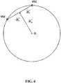
- the position of each virtual sound sourcecan be defined by a unitary source direction vector s j ( k , n ) originating from the reference listening point. This is shown in Fig. 5 .
- the first step of the source extractionconsists in determining the positions of the two virtual sound sources (step S121). As shown in Fig. 5 , each unitary source direction vector s j ( k , n ) is defined through the active directional vector D a ( k , n ) and reactive directional vector D r ( k , n ). More precisely, a virtual sound source is located at the intersection of
- the analyzed sound fieldis generated by two uncorrelated sound sources (not necessary of equal energy)
- this techniqueenables to retrieve the exact location of those two sound sources. If the two sound sources used to generate the sound field tend to be in-phase (respectively opposite-phase), their exact locations cannot be retrieved anymore.
- the techniqueover-estimates (respectively under-estimates) the spatial correlation between the two sound source directions. However, this relationship between signal correlation and spatial correlation is perceptively coherent.
- D r ⁇ k n ⁇ k n⁇ k n 2 ⁇ 4 ⁇ ⁇ k n ⁇ D
- the two virtual directional microphonesmay have a cardioid directivity patterns VM1, VM2 in the directions of the source direction vectors s 1 ( k , n ) s 2 ( k , n )
- the two virtual sound sources VS1, VS2are equivalent, in the sense that they contain both primary component (through the active directional vector D a ( k , n )) and ambient components (through the reactive directional vector D r ( k , n )).
- An ambience extraction processingmay be performed for implementing additional refinement.
- the first step of the audio source extractionconsists in determining the positions of the three virtual sound sources, through unitary source direction vectors s j ( k,n ) defined by the active directional vector D a ( k , n ) and reactive directional vector D r ( k , n ).
- the virtual sound sourcesare positioned on the unitary circle.
- a position of a virtual sound sourceis therefore at the intersection of the unitary circle with a directional line extending from the reference listening point.
- the position of each virtual sound sourcecan be defined by a unitary source direction vector s j ( k , n ) originating from the reference listening point.
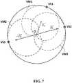
- the unitary source direction vector s j ( k , n )is defined through the active directional vector D a ( k , n ) and reactive directional vector D r ( k , n ). This is shown in Fig. 7 .
- the active directional vector D a ( k , n )indicates the main perceptual sound event direction
- the reactive intensityindicates the "direction of maximum perceptual diffuseness”.
- the three virtual directional microphonesmay have a cardioid directivity patterns VM1, VM2, VM3 in the directions of the source direction vectors s 1 ( k , n ), s 2 ( k , n ), s 3 ( k , n ).
- each virtual microphone signal M 1 ( k,n ) , M 2 ( k,n ) , M 3 ( k,n )highlights the sound of the corresponding virtual sound source VS1, VS2, VS3 perceived at the reference listening point O, but also contains interferences from the other virtual sound source VS1, VS2, VS3.
- step S13sound synthesis may be performed (step S13).
- the time-frequency signal values S j ( k,n ) of said virtual sound sourcesmay be distributed (step S33) to electroacoustic transducers on the basis of a comparison between the positions of the virtual sound sources in the virtual spatial configuration and the actual positions of said electroacoustic transducers in an actual spatial configuration. This might be called spatial synthesis.
- Fig. 6 and Fig. 8show the same actual spatial configuration with three electroacoustic transducers AET1, AET2, AET3 positioned at actual positions with respect to a reference listening point O.
- the first electroacoustic transducer AET1is arranged on the front of the reference listening point O, in a direction denoted by a first actual source direction vector b 1 .
- the second electroacoustic transducer AET2is arranged on the left of the reference listening point O, in a direction denoted by a second actual source direction vector b 2 , at a right angle with the first actual source direction vector b 1 .
- the third electroacoustic transducer AET3is arranged on the right of the reference listening point O, in a direction denoted by a third actual source direction vector b 3 , opposite to the second actual source direction vector b 2 .
- the electroacoustic transducersmay be loudspeaker, but also headphone.
- the various time-frequency signal values S j ( k,n ), associated virtual source direction vector s j ( k,n ),are used in conjunction with actual source direction vectors b h ( k , n ) in order to derive panning gains G jh ( k,n ) .
- Panning gains G jh ( k,n )define the sound level (and potentially phase) of each virtual sound source j within the output channel fed to the electroacoustic transducer h, for the time-frequency tile ( k,n ) .
- a panning gain G jh ( k,n )is determined by considering the geometric relationships between the virtual source direction vector s j ( k , n ) of the considered virtual sound source and the actual source direction vector b h of an electroacoustic transducer. To make it simple, the virtual source direction vector s j ( k , n ) is in some way projected onto the actual source direction vector b h ( k , n ). For example, in Fig. 6 , the second virtual sound source VS2 is much closer to the second electroacoustic transducer AET2 than the other electroacoustic transducer AET1, AET3.
- the panning gain G 22 ( k,n )will be greater than G 12 ( k,n ) or G 23 ( k , n ).
- a more complex trigonometric formulation or a vector based formulationmay be used.
- Vector-Based Amplitude Panning(VBAP) may be used, as disclosed by Ville Pulkki in "Virtual Sound Source Positioning Using Vector Base Amplitude Panning", Audio Engineering Society, Inc, 1997 .
- HRTFhead-related transfer function
- a virtual source direction vector s j ( k , n )may vary rapidly from one frame to the next one.
- the panning gains G jh ( k,n )may also vary abruptly from one frame to the next one.
- time-frequency audio output channel signals B h ( k,n )are then converted back into time-dependent output channel signals b h (t) .
- An Inverse Short-Time Fourier Transformation (ISTFT)may be used for that purpose.
- each time-dependent output channel signal b h ( t )is fed to each corresponding electroacoustic transducer, i.e. the electroacoustic transducer of said output channel.
- the electroacoustic transducerthen produces sounds from the received time-dependent output channel signals b h ( t ) (step S04).
- the method of the present invention as described abovecan be realized as a program and stored into a non-transitory tangible computer-readable medium, such as CD-ROM, ROM, hard-disk, having computer executable instructions embodied thereon that, when executed by a computer, perform the method according to the invention.
- a non-transitory tangible computer-readable mediumsuch as CD-ROM, ROM, hard-disk, having computer executable instructions embodied thereon that, when executed by a computer, perform the method according to the invention.
Landscapes
- Engineering & Computer Science (AREA)
- Physics & Mathematics (AREA)
- Acoustics & Sound (AREA)
- Signal Processing (AREA)
- Multimedia (AREA)
- Health & Medical Sciences (AREA)
- Theoretical Computer Science (AREA)
- Human Computer Interaction (AREA)
- Audiology, Speech & Language Pathology (AREA)
- Mathematical Physics (AREA)
- General Physics & Mathematics (AREA)
- Computational Linguistics (AREA)
- General Health & Medical Sciences (AREA)
- Mathematical Analysis (AREA)
- Mathematical Optimization (AREA)
- Algebra (AREA)
- Pure & Applied Mathematics (AREA)
- Spectroscopy & Molecular Physics (AREA)
- General Engineering & Computer Science (AREA)
- Otolaryngology (AREA)
- Stereophonic System (AREA)
Description
- The invention relates to a method for reproducing spatially distributed sounds of a multichannel audio signal.
- Audio is an important medium for conveying any kind of information, especially sound direction information. Indeed, the human auditory system is more effective than the visual system for surveillance tasks. Thanks to the development of multichannel audio format, spatialization has become a common feature in all domains of audio: movies, video games, virtual reality, music, etc.
- Typically, such sounds are mixed onto multiple audio channels, wherein each channel is fed to a dedicated loudspeaker. Distribution of a sound to the different channels is adapted to the configuration of the dedicated playback system (positions of the loudspeakers); so as to reproduce the intended directionality of said sound.
- Multichannel audio streams thus require to be played back over suitable loudspeaker layouts. For instance, each of the channels of a five channel formatted audio signal is associated with its corresponding loudspeaker within a five loudspeaker array.
Fig. 1 shows an example of a five channel loudspeaker layout recommended by the International Telecommunication Union (ITU) for the 5.1 surround sound configuration. There are a left loudspeaker L, right loudspeaker R, center loudspeaker C, surround left loudspeaker LS and surround right loudspeaker RS, arranged around a reference listening point O which is the recommended listener's position. With this reference listening point O as a center, the relative angular distances between the central directions of the loudspeakers are indicated. - A multichannel audio signal is thus encoded according to an audio file format dedicated to a prescribed spatial configuration where loudspeakers are arranged at prescribed positions to a reference listening point. Indeed, each time-dependent input audio signal of the multichannel audio signal is associated with a channel, each channel corresponding to a prescribed position of a loudspeaker.
- If multichannel audio is played back over an appropriate sound system, i.e. with the required number of loudspeakers and correct angular distances between them, a normal hearing listener is able to detect the location of the sound sources that compose the multichannel audio mix. However, should the actual sound system exhibit inappropriate features, such as too few loudspeakers, or an inaccurate angular distance thereof, the directional information of the audio content may not be delivered properly to the listener.
- Patent application
WO 2008/113428 A1 discloses a method wherein an input multi-channel representation is converted into a different output multi-channel representation of a spatial audio signal, an intermediate representation of the spatial audio signal is derived, the intermediate representation having direction parameters indicating a direction of origin of a portion of the spatial audio signal; and the output multi-channel representation of the spatial audio signal is generated using the intermediate representation of the spatial audio signal. - The method is intended to provide a method for reproducing spatially distributed sounds of a multichannel audio signal with an audio system comprising loudspeakers in an actual spatial configuration which is different of the prescribed spatial configuration associated with the format of the multichannel audio signal.
- In accordance with a first aspect of the present invention, this object is achieved by a method for reproducing spatially distributed sounds of a multichannel audio signal with electroacoustic transducers positioned at actual positions with respect to a reference listening point in an actual spatial configuration, wherein the multichannel audio signal comprises time-dependent input audio signals, each time-dependent input audio signal being associated with an input channel, each channel corresponding to a prescribed position of a electroacoustic transducer with respect to the reference listening point in a prescribed spatial configuration, said method comprising the following steps:
- receiving the time-dependent input audio signals,
- performing a time-frequency transform of said time-dependent input audio signals for converting each one of the time-dependent input audio signals into a plurality of time-frequency representations for the input channel associated with said time-dependent input audio signal, each time-frequency representation corresponding to a time-frequency tile defined by a time frame and a frequency sub-band, time-frequency tiles being the same for the different input channels,
- for each time-frequency tile, determining an active directional vector and a reactive directional vector from time-frequency representations of different input channels for said time-frequency tile, wherein the active directional vector is determined from a real part of a complex intensity vector and the reactive directional vector is determined from an imaginary part of the complex intensity vector,
- for each time-frequency tile, determining positions of virtual sound sources with respect to the reference listening point in a virtual spatial configuration from the active directional vector and the reactive directional vector, and determining frequency signal values to each virtual sound sources,
- distributing the time-frequency signal values of said virtual sound sources to electroacoustic transducers on the basis of a comparison between the positions of the virtual sound sources in the virtual spatial configuration and the actual positions of said electroacoustic transducers in an actual spatial configuration,
- producing sounds through the electroacoustic transducers of the actual spatial configuration on the basis of the time-frequency signal values distributed to the electroacoustic transducers.
- Other preferred, although non limitative, aspects of the method of the invention are as follows, isolated or in a technically feasible combination:
- the active directional vector of a time-frequency tile is representative of the sound energy flow at the reference listening point for the time frame and a frequency sub-band of said time-frequency tile, and wherein the reactive directional vector is representative of acoustic perturbations at the reference listening point with respect to the sound energy flow;
- each input channel is associated with a sound direction defined between the reference listening point and the prescribed position of the speaker associated with said input channel, and a sound velocity vector is determined as a function of a sum of each sound direction weighted by the time-frequency representation corresponding to the input channel associated with said sound direction, said sound velocity vector being used to determine the active directional vector and the reactive directional vector;
- a sound pressure value defined by a sum of the time-frequency representations of the different input channels is used to determine the active directional vector and the reactive directional vector;
- a complex intensity vector resulting from a complex product between a conjugate of the sound pressure value for a time-frequency tile and the sound velocity vector for said time-frequency tile is used to determine the active directional vector and the reactive directional vector of said time-frequency tile;
- the active directional vector is determined from the real part of the complex intensity vector and the reactive directional vector is determined from the imaginary part of the complex intensity vector;
- for determining time-frequency signal values of each one of the virtual sound sources, virtual microphone signals are determined, each virtual microphone signal being associated with a virtual sound source and corresponding to the signal that would acquire a virtual microphone arranged at the reference listening point and oriented in the direction toward the position of said virtual sound source;
- the time-frequency signal value of a virtual sound source is determined by suppressing, in the virtual microphone signal associated with said virtual sound source, the interferences from other virtual sound sources;
- time-frequency signal values are affected to each one of the virtual sound sources on the basis of the direction of the active directional vector and of the direction of the reactive directional vector;
- the virtual sound sources are arranged on a circle centered on the reference listening point;
- distributing the time-frequency signal values of said virtual sound sources to electroacoustic transducers on the basis of a comparison between the positions of the virtual sound sources in the virtual spatial configuration and the actual positions of said electroacoustic transducers in an actual spatial configuration comprises:
- for each time-frequency tile, calculating a time-frequency audio output channel signal by summing the respective contributions of each virtual sound sources for that output channel associated with an electroacoustic transducer, and
- converting time-frequency audio output channel signals into time-dependent output channel signals;
- each time-dependent output channel signal is fed to each corresponding electroacoustic transducer;
- there are three virtual sound sources for each time-frequency tile, each virtual sound source having a position with respect to the reference listening point, wherein:
- a position of a first virtual sound source defines with the reference listening point a direction which is collinear to the direction of the active directional vector from the reference listening point,
- a position of a second virtual sound source defines with the reference listening point a direction which is collinear to the direction of the reactive directional vector with a first orientation,
- a position of a third virtual sound source defines with the reference listening point a direction which is collinear to the direction of the reactive directional vector with a second orientation opposite to the first orientation.
- there are two virtual sound sources for each time-frequency tile, each virtual sound source having a position with respect to the reference listening point, and wherein:
- a position of a first virtual sound source defines with the reference listening point a direction resulting from the sum of the active directional vector and the reactive directional vector weighted by a positive factor, and
- a position of a second virtual sound source defines with the reference listening point a direction resulting from the sum of the active directional vector and the reactive directional vector weighted by a negative factor.
- In accordance with a second aspect of the present invention, there is provided a non-transitory tangible computer-readable medium having computer executable instructions embodied thereon that, when executed by a computer, perform the method according to the first aspect.
- In accordance with a third aspect of the present invention, there is provided a system for reproducing spatially distributed sounds of a multichannel audio signal, said system comprising:
- an input for receiving time-dependent input audio signals for a plurality of input channels,
- a processor and a memory for:
- performing a time-frequency transform of said time-dependent input audio signals for converting each one of the time-dependent input audio signals into a plurality of time-frequency representations for the input channel associated with said time-dependent input audio signal, each time-frequency representation corresponding to a time-frequency tile defined by a time frame and a frequency sub-band, time-frequency tiles being the same for the different input channels,
- for each time-frequency tile, determining an active directional vector and a reactive directional vector from time-frequency representations of different input channels for said time-frequency tile, wherein the active directional vector is determined from a real part of a complex intensity vector and the reactive directional vector is determined from an imaginary part of the complex intensity vector,
- for each time-frequency tile, determining positions of virtual sound sources with respect to the reference listening point in a virtual spatial configuration from the active directional vector and the reactive directional vector, and determining time-frequency signal values for each virtual sound sources,
- distributing the time-frequency signal values of said virtual sound sources to electroacoustic transducers on the basis of a comparison between the positions of the virtual sound sources in the virtual spatial configuration and the actual positions of said electroacoustic transducers in an actual spatial configuration; and
- an output for delivering time-dependent output channel signals to a plurality of electroacoustic transducers positioned at actual positions with respect to a reference listening point in an actual spatial configuration.
- The system is configured for implementing the method according to the invention.
- Other aspects, objects and advantages of the present invention will become better apparent upon reading the following detailed description of preferred embodiments thereof, given as a non-limiting example, and made with reference to the appended drawings wherein:
Fig. 1 , already discussed, shows an example of prescribed positions of loudspeakers with respect to a reference listening point in a prescribed spatial configuration for multichannel audio system;Fig. 2 is a diagram showing steps of the method;Fig. 3 is a diagram showing stages of the signal processing in the method;Fig. 4 shows schematically an example of a relationship between the active directional vector and the reactive directional vector with the locations of virtual sound sources;Fig. 5 shows schematically an example of a virtual spatial configuration with two virtual sound sources, and the active directional vector and the reactive directional vector, and the cardioids of the two corresponding virtual microphones;Fig. 6 shows schematically an example of an actual spatial configuration of three electroacoustic transducers and the two virtual sound sources ofFig. 5 ;Fig. 7 shows schematically an example of a virtual spatial configuration with three virtual sound sources and the cardioids of the three corresponding virtual microphones, as well as the active directional vector and the reactive directional vector;Fig. 8 shows schematically an example of an actual spatial configuration of three electroacoustic transducers and the three virtual sound sources ofFig. 7 .- The method may be implemented by a system for reproducing spatially distributed sounds of a multichannel audio signal, said system comprising:
- an input for receiving time-dependent input audio signals for a plurality of input channels,
- a processor and a memory configured to implement to method of the invention,
- an output for delivering time-dependent output channel signals to a plurality of electroacoustic transducers positioned at actual positions with respect to a reference listening point in an actual spatial configuration.
- An input receives the multichannel audio signal comprising time-dependent input audio signals for a plurality of input channels (step S01). Each time-dependent input audio signal is associated with an input channel. Each input channel corresponds to a prescribed position of an electroacoustic transducer with respect to a reference listening point in a prescribed spatial configuration. For example, in the prescribed spatial configuration shown by
Fig. 1 , there are five input channels, one for each loudspeaker LS, L, C, R, RS. - Under the plane-wave model assumption, the position of a sound source (e.g. the location of each loudspeaker) may be defined solely by the direction of the sound source with respect to the reference listening point. A unitary vector is then sufficient to locate a sound source. Accordingly, each of the prescribed positions defines a unitary vector
al representing the sound direction and originating from the reference listening point and pointing in the direction of each loudspeaker. As a result, each input channel i is associated with a sound directional defined between the reference listening point and the prescribed position of the loudspeaker associated with said input channel i. For example, in the prescribed spatial configuration shown inFig. 1 , the location of the loudspeaker C is defined by the sound vectoraC that originates from the reference listening point O and towards the location of the loudspeaker C on the unitary circle. This sound vectoraC extends in the front of the listening point. In a similar way, the location of the loudspeaker L is defined by the sound vectoraL that originates from the reference listening point O and towards the location of the loudspeaker L on the unitary circle. In this example, the directions of the sound vector

- However, the actual audio system intended to playback the multichannel audio signal comprises electroacoustic transducers positioned at actual positions with respect to the reference listening point in an actual spatial configuration. The method for reproducing spatially distributed sounds of a multichannel audio signal is described below in reference to
Fig. 2 andFig. 3 .Fig. 2 shows the temporally organized steps of the method, whileFig. 3 shows the mathematical reasoning of the method. - The received time-dependent input audio signalsai(t) may be analogue, but they preferably are digital signals. There are as many input audio signalsai(t) as input channelsi. During the frequency analysis (step S10), the time-dependent input audio signalsai(t) are converted into the frequency domain by performing a time-frequency conversion (step S02). Typically, the time-frequency conversion uses a Fourier-related transform such as a Short-time Fourier transform (STFT), which is used to determine the sinusoidal frequency and phase content of local sections of a signal as it changes over time.
- More precisely, each time-dependent input audio signalai(t) is converted into a plurality of time-frequency representationsAi(k,n) for the input channeli associated with said time-dependent input audio signal. Each time-frequency representationAi(k,n) corresponds to a time-frequency tile defined by a time frame and a frequency sub-band. The conversion is made on a frame-by-frame basis.
- Preferably, the frame length is comprised between 5 ms and 80 ms. Preferably, the width of the frequency sub-band is comprised between 10 Hz and 200 Hz. Preferably the inter-frame spacing is comprised between 1/16th and one half of the frame length.. For instance, for a sampling rate of 48 kHz and an FFT-based STFT processing framework, the frame length may be of 1024 samples with a related frequency sub-band width (or bin width) of 46.875 Hz and an inter-frame spacing of 512 samples. The time-frequency tiles are the same for the different input channels i.
- In the following,k is used as a frequency index of a frequency sub-band andn is a frame index, so that the time-frequency representationAi(k,n) refers to a complex number associated with thekth frequency sub-band and thenth frame of the signal of the input channel i.
- The time-frequency representationsAi(k,n) and the sound directions

- Spatial analysis (step S11) is performed from time-frequency representationsAi(k,n) and the sound directions
al of a time-frequency tile. For each time-frequency tile, an active directional vectorDa (k,n) and a reactive directional vectorDr (k,n) are determined (step S31) from time-frequency representationsAi(k,n) of different input channels for said time-frequency tile. - The active directional vector
Da (k,n) of a time-frequency tile is proportional to the active acoustical intensity vector which is representative of the sound energy flow at the reference listening point for the time frame and the frequency sub-band of said time-frequency tile. More specifically, the active directional vectorDa (k,n) corresponds to the active acoustical intensity vector, normalized by the sum of the acoustic energiesEP(k,n) andEK(k,n) at the reference listening point O, with an added minus sign in order to have it directed from the reference listening point O towards the unitary circle. It is possible to use a different normalization or to omit the minus sign, in which case the vectors would be pointing towards the reference listening point O. - The reactive directional vector
Dr (k,n) is proportional to the reactive acoustical intensity vector which is representative of acoustic perturbations at the reference listening point with respect to the sound energy flow for the same time-frequency tile. More specifically, the reactive directional vectorDr (k,n) corresponds to the reactive acoustical intensity vector, normalized by the sum of the acoustic energiesEP(k,n) andEK(k,n) at the reference listening point O. A minus sign is also added but could be omitted. As for the active directional vector, it is possible to use a different normalization. - From a perceptual point of view, if the active directional vector
Da (k,n) can be related to the primary directional sound field, the reactive directional vectorDr (k,n) is related to the ambient diffuse sound field. Moreover, the directional information of the reactive directional vectorDr (k,n) enables the handling of the spatial characteristics of this ambient sound field, and thus it can be used to describe not only totally diffused ambient sound fields but also partially diffused ones. - This new approach is by nature more robust as it takes benefits of the reliability of the active directional vector
Da (k,n) which is a true acoustical spatial cue (compared to the Gerzon vectors which are empiric perceptual cues), but also exploits the diffuseness of sound through the reactive directional vectorDr (k,n). - It has been found that the combination of the active directional vector
Da (k,n) and the reactive directional vectorDr (k,n) may be used to identify the locations of sound sources, as depicted onFig. 4 . In thisFig. 4 , sound distribution is represented by two virtual sound sources VS1 and VS2 arranged on a unitary circle centered on the reference listening point O. The active directional vectorDa (k,n) originates from the reference listening point O and is directed along the main acoustical flow. In this example, the two uncorrelated sound sources VS1, VS2 are of equal energy (for that time-frequency tile). As a result, the perceived acoustical energy flow at the reference listening point O comes from the middle of the two sound sources VS1, VS2, and therefore the active directional vectorDa (k,n) extends between the two sound sources VS1, VS2. The reactive directional vectorDr (k,n) is here perpendicular to the active directional vectorDa (k,n), and the location of a sound source VS1, VS2 corresponds to the sum of the active directional vectorDa (k,n) and of the reactive directional vectorDr (k,n) or of the opposite of the reactive directional vectorDr (k,n). - However, most of the time, the sound sources VS1, VS2 are not totally uncorrelated. It has been found that whatever the exact locations of the two sound sources VS1, VS2, the reactive intensity is maximal when the source signals are totally uncorrelated. Conversely, the reactive intensity is minimal when the source signals are totally correlated. In a similar way, where the sound source signals are totally uncorrelated, the reactive intensity is maximal when the source directions are spatially negatively correlated (i.e. opposite) with respect to the reference listening point O. Conversely, the reactive intensity is minimal when the source directions are spatially correlated (i.e. in the same direction) with respect to the reference listening point.
- For determining the active directional vector
Da (k,n) and the reactive directional vectorDr (k,n), the prescribed positions of the loudspeakers with respect to the reference listening point O in a prescribed spatial configuration are used. As indicated above, each input channeli is associated with a sound directional defined between the reference listening point O and the prescribed position of the loudspeaker associated with said input channeli. - A sound pressure valueP(k,n) for a time-frequency tile defined by a sum of the time-frequency representationsAi(k,n) of the different input channels of the same for said time-frequency tile is determined:

- A sound velocity vector
V (k,n) for the time-frequency tile is determined, said sound velocity vectorV (k,n) being proportional to a sum of each sound directiona l weighted by the time-frequency representationAi(k,n) corresponding to the input channeli associated with said sound directiona l :


- A complex intensity vector
I (k,n) resulting from a complex product between a conjugate of the sound pressure valueP(k,n) for a time-frequency tile and the sound velocity vectorV (k,n) for said time-frequency tile is determined:
Da (k,n) and the reactive directional vectorDr (k,n) of said time-frequency tile. More precisely, the active directional vectorDa (k,n) is determined from the real part of the complex productI (k,n)and the reactive directional vectorDr (k,n) is determined from the imaginary part of the complex productI (k,n). - The active directional vector
Da (k,n) and the reactive directional vectorDr (k,n) may be calculated as follows:

- It shall be noted that the active directional vector
Da (k,n) and the reactive directional vectorDr (k,n) are here normalized by the energiesEK(k,n) andEP(k,n), but could be calculated otherwise. It shall be noted that that a minus sign is added to the expressions of the active directional vectorDa (k,n) and reactive directional vectorDr (k,n) in order to have them directed from the reference listening point O towards the unitary circle. It would be possible to omit the minus sign, in which case the vectors would be pointing towards the reference listening point O. - Once the active directional vector
Da (k,n) the reactive directional vectorDr (k,n) the sound pressure valueP(k,n) and the sound velocity vectorV (k,n) (or the equivalents thereof) have been determined, it is possible to perform the audio source extraction (step S12) for determining positions and time-frequency signal values of virtual sound sources (step S32). - The method requires determining the attributes (position and time-frequency signal values) of virtual sound sources that will be used thereafter to determine the signals of the electroacoustic transducers of the actual spatial configuration.
- For each time-frequency tile, the active directional vector
Da (k,n) and the reactive directional vectorDr (k,n) are used to determine the positions of the virtual sound sources with respect to the reference listening point in a virtual spatial configuration (step S32). - The determined positions of the virtual sound sources, the active directional vector
Da (k,n) the reactive directional vectorDr (k,n) the sound pressure valueP(k,n) and the sound velocity vectorV (k,n) are used to determine virtual first-order directional microphone signals (step S122) corresponding to the sounds that would be acquired by virtual microphones arranged at the reference listening point O and directed towards each virtual sound sources. There are as many virtual microphones as virtual sound sources. - A virtual microphone signal is a function of the sum of the sound pressure valueP(k,n), and of the scalar product between the sound velocity vector
V (k,n) and a unitary vector in the direction of a sound source, possibly weighted by the density of airρ and the speed of soundc. For example, a virtual cardioid microphone signalMj(k,n) associated with a virtual sound source arranged in the direction defined bysj (k,n) can be calculated as follows:
- A virtual microphone signal highlights the sound of the corresponding virtual sound source perceived at the reference listening point O, but also contains interferences from the other virtual sound sources. However, defining the virtual microphone signals for every virtual sound source allows identifying the virtual sound source signal of each virtual sound source.
- It shall be noted that spatial manipulation may be performed by modifying the positions of the virtual sound sources. This approach is much safer than modifying the input channel data side defining the prescribed positions, because the original primary/ambient energy ratio is kept.
- The details of the source extraction process however change depending on the number of virtual sound sources. The audio source extraction process estimates the locations and frequency signal values of virtual sound sources that generate the same sound field characteristics as the sound field defined by the time-dependent input audio signals in the prescribed configuration. Source-related sound field models need to be defined, as the audio source extraction process may be highly different from one model to another. Indeed, two models are reliable with the analysis based on the exploitation of both the active and reactive components of the acoustical intensity, a model with two sound sources and a model with three sound sources.
- The "two-source" model handles the diffuseness (and thus makes use of the reactive component) as an indicator of the perceptual width of a sound source or local diffuseness. Two sound sources are sufficient to simulate a wider sound source, their spatial and signal correlation defining the perceived wideness of this composite sound source.
- The "three-source" model handles the diffuseness (and thus makes use of the reactive component) as an indicator of the ambience level within the sound scene or global diffuseness. Two uncorrelated sound sources of opposite directions are suitable to simulate this ambient component.
It is explained below how to proceed with two virtual sound sources or three virtual sound sources. - In a spatial configuration of a unitary circle centered on the reference listening point O, the virtual sound sources are positioned on the unitary circle. A position of a virtual sound source is therefore at the intersection of the unitary circle with a directional line extending from the reference listening point. The position of each virtual sound source can be defined by a unitary source direction vector
sj (k,n) originating from the reference listening point. This is shown inFig. 5 . - As indicated above, the first step of the source extraction consists in determining the positions of the two virtual sound sources (step S121). As shown in
Fig. 5 , each unitary source direction vectorsj (k,n) is defined through the active directional vectorDa (k,n) and reactive directional vectorDr (k,n). More precisely, a virtual sound source is located at the intersection of - the unitary circle and
- a line collinear with the reactive directional vector
Dr (k,n) and passing through the tip of the active directional vectorDa (k,n) originating from the reference listening point. - If the analyzed sound field is generated by two uncorrelated sound sources (not necessary of equal energy), this technique enables to retrieve the exact location of those two sound sources. If the two sound sources used to generate the sound field tend to be in-phase (respectively opposite-phase), their exact locations cannot be retrieved anymore. The technique over-estimates (respectively under-estimates) the spatial correlation between the two sound source directions. However, this relationship between signal correlation and spatial correlation is perceptively coherent.
- Determining the locations of the two virtual sound sources VS1, VS2 is equivalent to solving a geometry problem of the intersection of a line with a circle (or a sphere for three-dimensional sound field). Solving this problem is equivalent to solving a second order equation, which solutions are


- It shall be noted that there are:
- a position of a first virtual sound source VS1 defines, with the reference listening point O, a direction resulting from the sum of the active directional vector
Da (k,n) and the reactive directional vectorDr (k,n) weighted by a positive factor, and - a position of a second virtual sound source VS2 defines, with the reference listening point O, a direction resulting from the sum of the active directional vector
Da (k,n) and the reactive directional vectorDr (k,n) weighted by a negative factor. - We thus have a source direction vector
s1 (k,n) of a first virtual sound source VS1, and a source direction vectors2 (k,n) of a second virtual sound source VS2. As depicted inFig. 5 , these source direction vectorss1 (k,n),s2 (k,n) localize the virtual sound sources VS1, VS2 on the unitary circle centered on the reference listening point O. - As explained above, after the computation of the directions of the two virtual sound sources VS1, VS2, it is possible, by combining the sound pressure valueP(k,n) and the sound velocity vector
V (k,n) to the source direction vectorss1 (k,n)s2 (k,n), to create two virtual directional microphones. As depicted inFig. 5 , the two virtual directional microphones may have a cardioid directivity patterns VM1, VM2 in the directions of the source direction vectorss1 (k,n)s2 (k,n) The virtual microphone pick-up in these two directions may then be estimated by virtual microphone signalsM1(k,n),M2(k,n) defined as follows:
- As explained above, each virtual microphone signal highlights the sound signal of the corresponding virtual sound source VS1, VS2 perceived at the reference listening point O, but also contains interferences from the other virtual sound source:


- The positions of the two virtual sound sources VS1, VS2, defined by the source direction vectors
s1 (k,n) ands2 (k,n), and their respective time-frequency signal valuesS1(k,n) andS2(k,n) have been determined. - It shall be noted that the two virtual sound sources VS1, VS2 are equivalent, in the sense that they contain both primary component (through the active directional vector
Da (k,n)) and ambient components (through the reactive directional vectorDr (k,n)). An ambience extraction processing may be performed for implementing additional refinement. - As explained before, the first step of the audio source extraction consists in determining the positions of the three virtual sound sources, through unitary source direction vectors
sj (k,n) defined by the active directional vectorDa (k,n) and reactive directional vectorDr (k,n). In a spatial configuration of a unitary circle centered on the reference listening point O, the virtual sound sources are positioned on the unitary circle. A position of a virtual sound source is therefore at the intersection of the unitary circle with a directional line extending from the reference listening point. The position of each virtual sound source can be defined by a unitary source direction vectorsj (k,n) originating from the reference listening point. The unitary source direction vectorsj (k,n) is defined through the active directional vectorDa (k,n) and reactive directional vectorDr (k,n). This is shown inFig. 7 . - As already explained, the active directional vector
Da (k,n) indicates the main perceptual sound event direction, the reactive intensity indicates the "direction of maximum perceptual diffuseness". Using three virtual sound sources VS1, VS2, VS3 thus appears relevant to approximate the sound field properties: - one virtual sound source VS1 is in the direction of the active directional vector
Da (k,n) to represent the reconstruction of the main acoustic flow, and - two virtual sound sources VS2, VS3 negative spatially correlated, in the direction of the reactive directional vector
Dr (k,n) and its opposite direction, respectively, to represent the acoustic perturbations of the acoustic field. - As a consequence, there are:
- a position of a first virtual sound source VS1 defines with the reference listening point O a direction which is collinear to the direction of the active directional vector
Da (k,n) from the reference listening point, - a position of a second virtual sound source VS2 defines with the reference listening point O a direction which is collinear to the direction of the reactive directional vector
Dr (k,n) from the reference listening point with a first orientation, - a position of a third virtual sound source VS3 defines with the reference listening point a direction which is collinear to the direction of the reactive directional vector
Dr (k,n) from the reference listening point O with a second orientation opposite to the first orientation. - Indeed, determining the positions of the virtual sound sources VS1, VS2, VS3 is much simpler for the three-source model than for the two-source model, since their source direction vectors
sl (k,n) are directly computed from the active directional vectorDa (k,n) and the reactive directional vectorDr (k,n) :
s1 (k,n) of a first virtual sound source VS1, a second source direction vectors2 (k,n) of a second virtual sound source VS2, and a third source direction vectors3 (k,n) of a third virtual sound source VS3. As depicted inFig. 7 , these source direction vectors localize the virtual sound sources VS1, VS2, VS3 on the unitary circle centered on the reference listening point O. - As explained above, after the computation of the directions of the three virtual sound sources VS1, VS2, VS3, it is possible, by combining the sound pressure valueP(k,n), the sound velocity vector
V (k,n) to a source direction vector, to create three virtual directional microphones. As depicted inFig. 7 , the three virtual directional microphones may have a cardioid directivity patterns VM1, VM2, VM3 in the directions of the source direction vectorss1 (k,n),s2 (k,n),s3 (k,n). The virtual microphone pick-ups in these three directions may then be estimated by virtual microphone signals defined as follows:
- As explained above, each virtual microphone signalM1(k,n) ,M2(k,n) ,M3(k,n) highlights the sound of the corresponding virtual sound source VS1, VS2, VS3 perceived at the reference listening point O, but also contains interferences from the other virtual sound source VS1, VS2, VS3. More precisely, since the second source direction vector
s2 (k,n) and the third source direction vectors3 (k,n) are of opposite direction, interference between the second virtual sound source VS2 and the third virtual sound source VS3 is negligible, whereas they both interfere with the first virtual sound source VS1:

- A last processing step (step S123) permits to extract the time-frequency signal value of each virtual sound source by unmixing the source time-frequency values:

- Contrary to the model with two virtual sound sources, the three virtual sound sources are already decomposed between primary components and ambient components:
- the first virtual sound source VS1 corresponds to the primary component, and
- the second virtual sound source VS2 and third virtual sound source VS3 correspond to the ambient components. As a result, further refinement may be directly implemented without requiring an additional ambience extraction processing.
- Once the attributes of the virtual sound sources have been determined (positions and time-frequency signal values), sound synthesis may be performed (step S13). The time-frequency signal valuesSj(k,n) of said virtual sound sources may be distributed (step S33) to electroacoustic transducers on the basis of a comparison between the positions of the virtual sound sources in the virtual spatial configuration and the actual positions of said electroacoustic transducers in an actual spatial configuration. This might be called spatial synthesis.
- For doing so, spatial data relative to the actual positions of each electroacoustic transducerh are used. Spatial data are exemplified by actual source direction vectors
bh withh = 1,2,3, ...) originating from the reference listening point O and pointing in the direction of each electroacoustic transducer, as shown inFig. 6 andFig. 8 . BothFig. 6 andFig. 8 show the same actual spatial configuration with three electroacoustic transducers AET1, AET2, AET3 positioned at actual positions with respect to a reference listening point O. The first electroacoustic transducer AET1 is arranged on the front of the reference listening point O, in a direction denoted by a first actual source direction vectorb1. The second electroacoustic transducer AET2 is arranged on the left of the reference listening point O, in a direction denoted by a second actual source direction vectorb2, at a right angle with the first actual source direction vectorb1. The third electroacoustic transducer AET3 is arranged on the right of the reference listening point O, in a direction denoted by a third actual source direction vectorb3, opposite to the second actual source direction vectorb2. This is a mere example, and the method is not limited to a particular spatial layout of the electroacoustic transducers or to a particular number of electroacoustic transducers. The electroacoustic transducers may be loudspeaker, but also headphone. - For each time-frequency tile, the various time-frequency signal valuesSj(k,n), associated virtual source direction vector
sj (k,n), are used in conjunction with actual source direction vectorsb h(k,n) in order to derive panning gainsGjh(k,n). Panning gainsGjh(k,n) define the sound level (and potentially phase) of each virtual sound sourcej within the output channel fed to the electroacoustic transducerh, for the time-frequency tile (k,n). - A panning gainGjh(k,n) is determined by considering the geometric relationships between the virtual source direction vector
sj (k,n) of the considered virtual sound source and the actual source direction vectorbh of an electroacoustic transducer. To make it simple, the virtual source direction vectorsj (k,n) is in some way projected onto the actual source direction vectorbh (k,n). For example, inFig. 6 , the second virtual sound source VS2 is much closer to the second electroacoustic transducer AET2 than the other electroacoustic transducer AET1, AET3. The panning gainG22(k,n) will be greater thanG12(k,n) orG23(k,n). Of course, in practice, a more complex trigonometric formulation or a vector based formulation may be used. For instance, Vector-Based Amplitude Panning (VBAP) may be used, as disclosed byVille Pulkki in "Virtual Sound Source Positioning Using Vector Base Amplitude Panning", Audio Engineering Society, Inc, 1997. - It shall be noted that it is possible to also implement a head-related transfer function (HRTF) processing in order to synthesize a binaural sound. Since the HRTF may depend on the virtual sound source location, a set of predetermined HRTFs may be stored, and the HRTF to be used selected on the basis of the locations of the virtual sound sources, as explained byMichael M. Goodwin and Jean-Marc Jot in "Binaural 3D audio rendering based on spatial audio scene coding", Audio Engineering Society, 123rd Convention, New York, NY, 2007.
- For the same frequency bin, a virtual source direction vector
sj (k,n) may vary rapidly from one frame to the next one. As a result, the panning gainsGjh(k,n), may also vary abruptly from one frame to the next one. The panning gainsGjh(k,n) may be smoothed by combining at least two temporally successive panning gainsGjh(k,n) of the same frequency bin, such as:
- For each time-frequency tile, the time-frequency audio output channel signalBh(k,n) is then calculated by summing the respective contributions of each virtual sound source for that output channel:

- The time-frequency audio output channel signalsBh(k,n) are then converted back into time-dependent output channel signalsbh(t). An Inverse Short-Time Fourier Transformation (ISTFT) may be used for that purpose.
- Finally, each time-dependent output channel signalbh(t) is fed to each corresponding electroacoustic transducer, i.e. the electroacoustic transducer of said output channel. The electroacoustic transducer then produces sounds from the received time-dependent output channel signalsbh(t) (step S04).
- The method of the present invention as described above can be realized as a program and stored into a non-transitory tangible computer-readable medium, such as CD-ROM, ROM, hard-disk, having computer executable instructions embodied thereon that, when executed by a computer, perform the method according to the invention.
- While the present invention has been described with respect to certain preferred embodiments, it will be apparent to those skilled in the art that various changes and modifications may be made without departing from the scope of the invention as defined in the appended claims.


Claims (15)
- A method for reproducing spatially distributed sounds of a multichannel audio signal with electroacoustic transducers (AET1, AET2, AET3) positioned at actual positions with respect to a reference listening point (O) in an actual spatial configuration, wherein the multichannel audio signal comprises time-dependent input audio signals, each time-dependent input audio signal being associated with an input channel, each channel corresponding to a prescribed position of a electroacoustic transducer with respect to the reference listening point (O) in a prescribed spatial configuration, said method comprising the following steps:- receiving (S01) the time-dependent input audio signals,- performing a time-frequency conversion (S02) of said time-dependent input audio signals for converting each one of the time-dependent input audio signals into a plurality of time-frequency representations for the input channel associated with said time-dependent input audio signal, each time-frequency representation corresponding to a time-frequency tile defined by a time frame and a frequency sub-band, time-frequency tiles being the same for the different input channels,- for each time-frequency tile, determining (S31) an active directional vector
Da and a reactive directional vectorDr from time-frequency representations of different input channels for said time-frequency tile, wherein the active directional vector is determined from a real part of a complex intensity vector and the reactive directional vector is determined from an imaginary part of the complex intensity vector,- for each time-frequency tile, determining positions of virtual sound sources (VS1, VS2, VS3) with respect to the reference listening point (O) in a virtual spatial configuration from the active directional vectorDa and the reactive directional vectorDr, and determining time-frequency signal values to each of said virtual sound sources (VS1, VS2, VS3) (S32),- distributing (S33) the time-frequency signal values of said virtual sound sources (VS1, VS2, VS3) to electroacoustic transducers (AET1, AET2, AET3) on the basis of a comparison between the positions of the virtual sound sources in the virtual spatial configuration and the actual positions of said electroacoustic transducers (AET1, AET2, AET3) in an actual spatial configuration,- producing (S04) sounds through the electroacoustic transducers of the actual spatial configuration on the basis of the time-frequency signal values distributed to the electroacoustic transducers. - The method of claim 1, wherein the active directional vector (
Da ) of a time-frequency tile is representative of the sound energy flow at the reference listening point for the time frame and a frequency sub-band of said time-frequency tile, and wherein the reactive directional vector (Dr ) is representative of acoustic perturbations at the reference listening point with respect to the sound energy flow. - The method according to any one of the preceding claims, wherein each input channel is associated with a sound direction (
al ) defined between the reference listening point and the prescribed position of the speaker associated with said input channel, and a sound velocity vector is determined as a function of a sum of each sound direction (al ) weighted by the time-frequency representation corresponding to the input channel associated with said sound direction, said sound velocity vector being used to determine the active directional vector (Da ) and the reactive directional vector (Dr ). - The method according to any one of the preceding claims, wherein a sound pressure value defined by a sum of the time-frequency representations of the different input channels is used to determine the active directional vector (
Da ) and the reactive directional vector (Dr ). - The method according to claims 3 and 4, wherein a complex intensity vector resulting from a complex product between a conjugate of the sound pressure value for a time-frequency tile and the sound velocity vector for said time-frequency tile is used to determine the active directional vector and the reactive directional vector of said time-frequency tile.
- The method according to the preceding claim, wherein the active directional vector is determined from the real part of the complex intensity vector and the reactive directional vector is determined from the imaginary part of the complex intensity vector.
- The method according to any one preceding claims, wherein for determining time-frequency signal values of each one of the virtual sound sources, virtual microphone signals are determined, each virtual microphone signal being associated with a virtual sound source and corresponding to the signal that would acquire a virtual microphone arranged at the reference listening point (O) and oriented in the direction toward the position of said virtual sound source.
- The method according to claim 7, wherein the time-frequency signal value of a virtual sound source is determined by suppressing, in the virtual microphone signal associated with said virtual sound source, the interferences from other virtual sound sources.
- The method according to claim 7 or claim 8, wherein the virtual sound sources are arranged on a circle centered on the reference listening point (O) and a virtual microphone signal corresponds to the signal that would acquire a virtual cardioid microphone having an cardioid directivity pattern (VM1, VM2, VM3) in the shape of a cardioid tangential to the circle centered on the reference listening point (O).
- The method according to any one of the preceding claims, wherein distributing the time-frequency signal values of said virtual sound sources (VS1, VS2, VS3) to electroacoustic transducers (AET1, AET2, AET3) on the basis of a comparison between the positions of the virtual sound sources in the virtual spatial configuration and the actual positions of said electroacoustic transducers (AET1, AET2, AET3) in an actual spatial configuration comprises:- for each time-frequency tile, calculating a time-frequency audio output channel signal by summing the respective contributions of each virtual sound sources for that output channel associated with an electroacoustic transducer, and- converting time-frequency audio output channel signals into time-dependent output channel signals.
- The method according to claim 10, wherein each time-dependent output channel signal is fed to each corresponding electroacoustic transducer.
- The method according to any one of the preceding claims, wherein there are three virtual sound sources for each time-frequency tile, each virtual sound source having a position with respect to the reference listening point, wherein:- a position of a first virtual sound source (VS1) defines with the reference listening point (O) a direction
s1 which is collinear to the direction of the active directional vectorDa from the reference listening point (O),- a position of a second virtual sound source (VS2) defines with the reference listening point (O) a directions2 which is collinear to the direction of the reactive directional vectorDr with a first orientation,- a position of a third virtual sound source (VS3) defines with the reference listening point (O) a directions3 which is collinear to the direction of the reactive directional vectorDr with a second orientation opposite to the first orientation. - The method according to any one of the preceding claims, wherein there are two virtual sound sources for each time-frequency tile, each virtual sound source having a position with respect to the reference listening point, and wherein:- a position of a first virtual sound source (VS1) defines with the reference listening point (O) a direction
s1 resulting from the sum of the active directional vectorDa and the reactive directional vectorDr weighted by a positive factor, and- a position of a second virtual sound source (VS2) defines with the reference listening point (O) a directions2 resulting from the sum of the active directional vectorDa and the reactive directional vectorDr weighted by a negative factor. - A non-transitory tangible computer-readable medium having computer executable instructions embodied thereon that, when executed by a computer, perform the method of any one of the preceding claims.
- A system for reproducing spatially distributed sounds of a multichannel audio signal, said system comprising:- an input for receiving time-dependent input audio signals for a plurality of input channels,- a processor and a memory for:• performing a time-frequency transform of said time-dependent input audio signals for converting each one of the time-dependent input audio signals into a plurality of time-frequency representationsAi for the input channel associated with said time-dependent input audio signal, each time-frequency representationAi corresponding to a time-frequency tile defined by a time frame and a frequency sub-band, time-frequency tiles being the same for the different input channels,• for each time-frequency tile, determining an active directional vector
Da and a reactive directional vectorDr from time-frequency representationsAi of different input channels for said time-frequency tile, wherein the active directional vector is determined from a real part of a complex intensity vector and the reactive directional vector is determined from an imaginary part of the complex intensity vector,• for each time-frequency tile, determining positions of virtual sound sources with respect to the reference listening point in a virtual spatial configuration from the active directional vectorDa and the reactive directional vectorDr , and determining time-frequency signal values for each of said virtual sound sources,• distributing the time-frequency signal values of said virtual sound sources to electroacoustic transducers on the basis of a comparison between the positions of the virtual sound sources in the virtual spatial configuration and the actual positions of said electroacoustic transducers in an actual spatial configuration; and- an output for delivering time-dependent output channel signals to a plurality of electroacoustic transducers (AET1, AET2, AET3) positioned at actual positions with respect to a reference listening point (O) in an actual spatial configuration.
Priority Applications (7)
| Application Number | Priority Date | Filing Date | Title |
|---|---|---|---|
| EP16306190.6AEP3297298B1 (en) | 2016-09-19 | 2016-09-19 | Method for reproducing spatially distributed sounds |
| US15/707,129US20180084364A1 (en) | 2016-09-19 | 2017-09-18 | Method for Visualizing the Directional Sound Activity of a Multichannel Audio Signal |
| US16/334,333US10536793B2 (en) | 2016-09-19 | 2017-09-19 | Method for reproducing spatially distributed sounds |
| CN201780057585.2ACN110089134B (en) | 2016-09-19 | 2017-09-19 | Method, system and computer readable medium for reproducing spatially distributed sound |
| PCT/EP2017/073565WO2018050905A1 (en) | 2016-09-19 | 2017-09-19 | Method for reproducing spatially distributed sounds |
| TW106132102ATWI770059B (en) | 2016-09-19 | 2017-09-19 | Method for reproducing spatially distributed sounds |
| US15/708,579US10085108B2 (en) | 2016-09-19 | 2017-09-19 | Method for visualizing the directional sound activity of a multichannel audio signal |
Applications Claiming Priority (1)
| Application Number | Priority Date | Filing Date | Title |
|---|---|---|---|
| EP16306190.6AEP3297298B1 (en) | 2016-09-19 | 2016-09-19 | Method for reproducing spatially distributed sounds |
Publications (2)
| Publication Number | Publication Date |
|---|---|
| EP3297298A1 EP3297298A1 (en) | 2018-03-21 |
| EP3297298B1true EP3297298B1 (en) | 2020-05-06 |
Family
ID=57130308
Family Applications (1)
| Application Number | Title | Priority Date | Filing Date |
|---|---|---|---|
| EP16306190.6AActiveEP3297298B1 (en) | 2016-09-19 | 2016-09-19 | Method for reproducing spatially distributed sounds |
Country Status (5)
| Country | Link |
|---|---|
| US (3) | US20180084364A1 (en) |
| EP (1) | EP3297298B1 (en) |
| CN (1) | CN110089134B (en) |
| TW (1) | TWI770059B (en) |
| WO (1) | WO2018050905A1 (en) |
Cited By (1)
| Publication number | Priority date | Publication date | Assignee | Title |
|---|---|---|---|---|
| US11902769B2 (en) | 2019-07-02 | 2024-02-13 | Dolby International Ab | Methods, apparatus and systems for representation, encoding, and decoding of discrete directivity data |
Families Citing this family (80)
| Publication number | Priority date | Publication date | Assignee | Title |
|---|---|---|---|---|
| US8930005B2 (en) | 2012-08-07 | 2015-01-06 | Sonos, Inc. | Acoustic signatures in a playback system |
| US9947316B2 (en) | 2016-02-22 | 2018-04-17 | Sonos, Inc. | Voice control of a media playback system |
| US10264030B2 (en) | 2016-02-22 | 2019-04-16 | Sonos, Inc. | Networked microphone device control |
| US10095470B2 (en) | 2016-02-22 | 2018-10-09 | Sonos, Inc. | Audio response playback |
| US9826306B2 (en) | 2016-02-22 | 2017-11-21 | Sonos, Inc. | Default playback device designation |
| US9965247B2 (en) | 2016-02-22 | 2018-05-08 | Sonos, Inc. | Voice controlled media playback system based on user profile |
| US9811314B2 (en) | 2016-02-22 | 2017-11-07 | Sonos, Inc. | Metadata exchange involving a networked playback system and a networked microphone system |
| US9978390B2 (en) | 2016-06-09 | 2018-05-22 | Sonos, Inc. | Dynamic player selection for audio signal processing |
| US10134399B2 (en) | 2016-07-15 | 2018-11-20 | Sonos, Inc. | Contextualization of voice inputs |
| US10152969B2 (en) | 2016-07-15 | 2018-12-11 | Sonos, Inc. | Voice detection by multiple devices |
| US10115400B2 (en) | 2016-08-05 | 2018-10-30 | Sonos, Inc. | Multiple voice services |
| US9942678B1 (en) | 2016-09-27 | 2018-04-10 | Sonos, Inc. | Audio playback settings for voice interaction |
| US9743204B1 (en) | 2016-09-30 | 2017-08-22 | Sonos, Inc. | Multi-orientation playback device microphones |
| US10181323B2 (en) | 2016-10-19 | 2019-01-15 | Sonos, Inc. | Arbitration-based voice recognition |
| US11183181B2 (en) | 2017-03-27 | 2021-11-23 | Sonos, Inc. | Systems and methods of multiple voice services |
| US10475449B2 (en) | 2017-08-07 | 2019-11-12 | Sonos, Inc. | Wake-word detection suppression |
| US10048930B1 (en) | 2017-09-08 | 2018-08-14 | Sonos, Inc. | Dynamic computation of system response volume |
| US10446165B2 (en) | 2017-09-27 | 2019-10-15 | Sonos, Inc. | Robust short-time fourier transform acoustic echo cancellation during audio playback |
| US10621981B2 (en) | 2017-09-28 | 2020-04-14 | Sonos, Inc. | Tone interference cancellation |
| US10051366B1 (en) | 2017-09-28 | 2018-08-14 | Sonos, Inc. | Three-dimensional beam forming with a microphone array |
| US10482868B2 (en) | 2017-09-28 | 2019-11-19 | Sonos, Inc. | Multi-channel acoustic echo cancellation |
| WO2019067620A1 (en) | 2017-09-29 | 2019-04-04 | Zermatt Technologies Llc | Spatial audio downmixing |
| US10466962B2 (en) | 2017-09-29 | 2019-11-05 | Sonos, Inc. | Media playback system with voice assistance |
| CN107890673A (en)* | 2017-09-30 | 2018-04-10 | 网易(杭州)网络有限公司 | Visual display method and device, storage medium, the equipment of compensating sound information |
| US10880650B2 (en) | 2017-12-10 | 2020-12-29 | Sonos, Inc. | Network microphone devices with automatic do not disturb actuation capabilities |
| US10818290B2 (en) | 2017-12-11 | 2020-10-27 | Sonos, Inc. | Home graph |
| US11343614B2 (en) | 2018-01-31 | 2022-05-24 | Sonos, Inc. | Device designation of playback and network microphone device arrangements |
| GB2572419A (en)* | 2018-03-29 | 2019-10-02 | Nokia Technologies Oy | Spatial sound rendering |
| GB2572420A (en) | 2018-03-29 | 2019-10-02 | Nokia Technologies Oy | Spatial sound rendering |
| US11175880B2 (en) | 2018-05-10 | 2021-11-16 | Sonos, Inc. | Systems and methods for voice-assisted media content selection |
| US10847178B2 (en) | 2018-05-18 | 2020-11-24 | Sonos, Inc. | Linear filtering for noise-suppressed speech detection |
| US10959029B2 (en) | 2018-05-25 | 2021-03-23 | Sonos, Inc. | Determining and adapting to changes in microphone performance of playback devices |
| CN108854069B (en) | 2018-05-29 | 2020-02-07 | 腾讯科技(深圳)有限公司 | Sound source determination method and device, storage medium and electronic device |
| US10681460B2 (en) | 2018-06-28 | 2020-06-09 | Sonos, Inc. | Systems and methods for associating playback devices with voice assistant services |
| US11076035B2 (en) | 2018-08-28 | 2021-07-27 | Sonos, Inc. | Do not disturb feature for audio notifications |
| US10461710B1 (en) | 2018-08-28 | 2019-10-29 | Sonos, Inc. | Media playback system with maximum volume setting |
| EP3618464A1 (en)* | 2018-08-30 | 2020-03-04 | Nokia Technologies Oy | Reproduction of parametric spatial audio using a soundbar |
| US10587430B1 (en)* | 2018-09-14 | 2020-03-10 | Sonos, Inc. | Networked devices, systems, and methods for associating playback devices based on sound codes |
| US10878811B2 (en) | 2018-09-14 | 2020-12-29 | Sonos, Inc. | Networked devices, systems, and methods for intelligently deactivating wake-word engines |
| CN109036456B (en)* | 2018-09-19 | 2022-10-14 | 电子科技大学 | Ambient Component Extraction Method for Source Component for Stereo |
| US11024331B2 (en) | 2018-09-21 | 2021-06-01 | Sonos, Inc. | Voice detection optimization using sound metadata |
| US10811015B2 (en) | 2018-09-25 | 2020-10-20 | Sonos, Inc. | Voice detection optimization based on selected voice assistant service |
| US11100923B2 (en) | 2018-09-28 | 2021-08-24 | Sonos, Inc. | Systems and methods for selective wake word detection using neural network models |
| US10692518B2 (en) | 2018-09-29 | 2020-06-23 | Sonos, Inc. | Linear filtering for noise-suppressed speech detection via multiple network microphone devices |
| US11899519B2 (en) | 2018-10-23 | 2024-02-13 | Sonos, Inc. | Multiple stage network microphone device with reduced power consumption and processing load |
| EP3654249A1 (en) | 2018-11-15 | 2020-05-20 | Snips | Dilated convolutions and gating for efficient keyword spotting |
| US11183183B2 (en) | 2018-12-07 | 2021-11-23 | Sonos, Inc. | Systems and methods of operating media playback systems having multiple voice assistant services |
| US11132989B2 (en) | 2018-12-13 | 2021-09-28 | Sonos, Inc. | Networked microphone devices, systems, and methods of localized arbitration |
| US10602268B1 (en) | 2018-12-20 | 2020-03-24 | Sonos, Inc. | Optimization of network microphone devices using noise classification |
| US10867604B2 (en) | 2019-02-08 | 2020-12-15 | Sonos, Inc. | Devices, systems, and methods for distributed voice processing |
| US11315556B2 (en) | 2019-02-08 | 2022-04-26 | Sonos, Inc. | Devices, systems, and methods for distributed voice processing by transmitting sound data associated with a wake word to an appropriate device for identification |
| EP3935872A1 (en) | 2019-03-04 | 2022-01-12 | Steelseries France | Apparatus and method for audio analysis |
| US11120794B2 (en) | 2019-05-03 | 2021-09-14 | Sonos, Inc. | Voice assistant persistence across multiple network microphone devices |
| US10586540B1 (en) | 2019-06-12 | 2020-03-10 | Sonos, Inc. | Network microphone device with command keyword conditioning |
| US11361756B2 (en) | 2019-06-12 | 2022-06-14 | Sonos, Inc. | Conditional wake word eventing based on environment |
| US11200894B2 (en) | 2019-06-12 | 2021-12-14 | Sonos, Inc. | Network microphone device with command keyword eventing |
| US11138975B2 (en) | 2019-07-31 | 2021-10-05 | Sonos, Inc. | Locally distributed keyword detection |
| US10871943B1 (en) | 2019-07-31 | 2020-12-22 | Sonos, Inc. | Noise classification for event detection |
| US11138969B2 (en) | 2019-07-31 | 2021-10-05 | Sonos, Inc. | Locally distributed keyword detection |
| GB2587196A (en)* | 2019-09-13 | 2021-03-24 | Nokia Technologies Oy | Determination of spatial audio parameter encoding and associated decoding |
| US11189286B2 (en) | 2019-10-22 | 2021-11-30 | Sonos, Inc. | VAS toggle based on device orientation |
| US12010493B1 (en)* | 2019-11-13 | 2024-06-11 | EmbodyVR, Inc. | Visualizing spatial audio |
| US11291911B2 (en) | 2019-11-15 | 2022-04-05 | Microsoft Technology Licensing, Llc | Visualization of sound data extending functionality of applications/services including gaming applications/services |
| US11200900B2 (en) | 2019-12-20 | 2021-12-14 | Sonos, Inc. | Offline voice control |
| US11562740B2 (en) | 2020-01-07 | 2023-01-24 | Sonos, Inc. | Voice verification for media playback |
| US11556307B2 (en) | 2020-01-31 | 2023-01-17 | Sonos, Inc. | Local voice data processing |
| US11308958B2 (en) | 2020-02-07 | 2022-04-19 | Sonos, Inc. | Localized wakeword verification |
| CN111372167B (en) | 2020-02-24 | 2021-10-26 | Oppo广东移动通信有限公司 | Sound effect optimization method and device, electronic equipment and storage medium |
| US11308962B2 (en) | 2020-05-20 | 2022-04-19 | Sonos, Inc. | Input detection windowing |
| US11482224B2 (en) | 2020-05-20 | 2022-10-25 | Sonos, Inc. | Command keywords with input detection windowing |
| US11727919B2 (en) | 2020-05-20 | 2023-08-15 | Sonos, Inc. | Memory allocation for keyword spotting engines |
| US12387716B2 (en) | 2020-06-08 | 2025-08-12 | Sonos, Inc. | Wakewordless voice quickstarts |
| DE102020209050B4 (en)* | 2020-07-20 | 2022-05-25 | Sivantos Pte. Ltd. | Method for operating a hearing system, hearing system, hearing aid |
| US11698771B2 (en) | 2020-08-25 | 2023-07-11 | Sonos, Inc. | Vocal guidance engines for playback devices |
| US12283269B2 (en) | 2020-10-16 | 2025-04-22 | Sonos, Inc. | Intent inference in audiovisual communication sessions |
| US11984123B2 (en) | 2020-11-12 | 2024-05-14 | Sonos, Inc. | Network device interaction by range |
| US11551700B2 (en) | 2021-01-25 | 2023-01-10 | Sonos, Inc. | Systems and methods for power-efficient keyword detection |
| EP4409933A1 (en) | 2021-09-30 | 2024-08-07 | Sonos, Inc. | Enabling and disabling microphones and voice assistants |
| US12327549B2 (en) | 2022-02-09 | 2025-06-10 | Sonos, Inc. | Gatekeeping for voice intent processing |
| CN114915881A (en)* | 2022-04-15 | 2022-08-16 | 青岛虚拟现实研究院有限公司 | Control method, electronic device and storage medium for virtual reality headset |
Family Cites Families (28)
| Publication number | Priority date | Publication date | Assignee | Title |
|---|---|---|---|---|
| GB9417185D0 (en)* | 1994-08-25 | 1994-10-12 | Adaptive Audio Ltd | Sounds recording and reproduction systems |
| CN100358393C (en) | 1999-09-29 | 2007-12-26 | 1...有限公司 | Method and apparatus for directing sound |
| JP2004144912A (en)* | 2002-10-23 | 2004-05-20 | Matsushita Electric Ind Co Ltd | Voice information conversion method, voice information conversion program, and voice information conversion device |
| FI118247B (en) | 2003-02-26 | 2007-08-31 | Fraunhofer Ges Forschung | Method for creating a natural or modified space impression in multi-channel listening |
| CA2551998C (en) | 2003-12-30 | 2015-11-17 | Nielsen Media Research, Inc. | Methods and apparatus to distinguish a signal originating from a local device from a broadcast signal |
| EP1779385B1 (en)* | 2004-07-09 | 2010-09-22 | Electronics and Telecommunications Research Institute | Method and apparatus for encoding and decoding multi-channel audio signal using virtual source location information |
| EP1761110A1 (en) | 2005-09-02 | 2007-03-07 | Ecole Polytechnique Fédérale de Lausanne | Method to generate multi-channel audio signals from stereo signals |
| KR100644715B1 (en)* | 2005-12-19 | 2006-11-10 | 삼성전자주식회사 | Active audio matrix decoding method and apparatus |
| KR100852223B1 (en) | 2006-02-03 | 2008-08-13 | 한국전자통신연구원 | Apparatus and method for visualizing multichannel audio signals |
| JP3949701B1 (en)* | 2006-03-27 | 2007-07-25 | 株式会社コナミデジタルエンタテインメント | Voice processing apparatus, voice processing method, and program |
| US9014377B2 (en)* | 2006-05-17 | 2015-04-21 | Creative Technology Ltd | Multichannel surround format conversion and generalized upmix |
| US8374365B2 (en) | 2006-05-17 | 2013-02-12 | Creative Technology Ltd | Spatial audio analysis and synthesis for binaural reproduction and format conversion |
| US8379868B2 (en) | 2006-05-17 | 2013-02-19 | Creative Technology Ltd | Spatial audio coding based on universal spatial cues |
| US8908873B2 (en) | 2007-03-21 | 2014-12-09 | Fraunhofer-Gesellschaft Zur Foerderung Der Angewandten Forschung E.V. | Method and apparatus for conversion between multi-channel audio formats |
| US8290167B2 (en)* | 2007-03-21 | 2012-10-16 | Fraunhofer-Gesellschaft Zur Foerderung Der Angewandten Forschung E.V. | Method and apparatus for conversion between multi-channel audio formats |
| CA2748301C (en) | 2008-12-30 | 2017-06-27 | Karen Collins | Method and system for visual representation of sound |
| PL2285139T3 (en) | 2009-06-25 | 2020-03-31 | Dts Licensing Limited | Device and method for converting spatial audio signal |
| US8208002B2 (en) | 2009-08-27 | 2012-06-26 | Polycom, Inc. | Distance learning via instructor immersion into remote classroom |
| CN102630385B (en)* | 2009-11-30 | 2015-05-27 | 诺基亚公司 | Method, device and system for audio scaling processing in audio scene |
| KR101081752B1 (en)* | 2009-11-30 | 2011-11-09 | 한국과학기술연구원 | Artificial Ear and Method for Detecting the Direction of a Sound Source Using the Same |
| ES2656815T3 (en) | 2010-03-29 | 2018-02-28 | Fraunhofer-Gesellschaft Zur Förderung Der Angewandten Forschung | Spatial audio processor and procedure to provide spatial parameters based on an acoustic input signal |
| FR2996094B1 (en)* | 2012-09-27 | 2014-10-17 | Sonic Emotion Labs | METHOD AND SYSTEM FOR RECOVERING AN AUDIO SIGNAL |
| EP2733965A1 (en) | 2012-11-15 | 2014-05-21 | Fraunhofer-Gesellschaft zur Förderung der angewandten Forschung e.V. | Apparatus and method for generating a plurality of parametric audio streams and apparatus and method for generating a plurality of loudspeaker signals |
| US9232337B2 (en)* | 2012-12-20 | 2016-01-05 | A-Volute | Method for visualizing the directional sound activity of a multichannel audio signal |
| JP2014219467A (en)* | 2013-05-02 | 2014-11-20 | ソニー株式会社 | Sound signal processing apparatus, sound signal processing method, and program |
| US9852737B2 (en) | 2014-05-16 | 2017-12-26 | Qualcomm Incorporated | Coding vectors decomposed from higher-order ambisonics audio signals |
| US20150332682A1 (en) | 2014-05-16 | 2015-11-19 | Qualcomm Incorporated | Spatial relation coding for higher order ambisonic coefficients |
| CN105392102B (en)* | 2015-11-30 | 2017-07-25 | 武汉大学 | Three-dimensional audio signal generation method and system for aspheric loudspeaker array |
- 2016
- 2016-09-19EPEP16306190.6Apatent/EP3297298B1/enactiveActive
- 2017
- 2017-09-18USUS15/707,129patent/US20180084364A1/ennot_activeAbandoned
- 2017-09-19USUS16/334,333patent/US10536793B2/enactiveActive
- 2017-09-19CNCN201780057585.2Apatent/CN110089134B/enactiveActive
- 2017-09-19USUS15/708,579patent/US10085108B2/enactiveActive
- 2017-09-19WOPCT/EP2017/073565patent/WO2018050905A1/ennot_activeCeased
- 2017-09-19TWTW106132102Apatent/TWI770059B/enactive
Non-Patent Citations (1)
| Title |
|---|
| None* |
Cited By (2)
| Publication number | Priority date | Publication date | Assignee | Title |
|---|---|---|---|---|
| US11902769B2 (en) | 2019-07-02 | 2024-02-13 | Dolby International Ab | Methods, apparatus and systems for representation, encoding, and decoding of discrete directivity data |
| US12369007B2 (en) | 2019-07-02 | 2025-07-22 | Dolby International Ab | Methods, apparatus and systems for representation, encoding, and decoding of discrete directivity data |
Also Published As
| Publication number | Publication date |
|---|---|
| CN110089134B (en) | 2021-06-22 |
| US20180084367A1 (en) | 2018-03-22 |
| US20190208349A1 (en) | 2019-07-04 |
| CN110089134A (en) | 2019-08-02 |
| EP3297298A1 (en) | 2018-03-21 |
| US10085108B2 (en) | 2018-09-25 |
| WO2018050905A1 (en) | 2018-03-22 |
| TWI770059B (en) | 2022-07-11 |
| US20180084364A1 (en) | 2018-03-22 |
| TW201820898A (en) | 2018-06-01 |
| US10536793B2 (en) | 2020-01-14 |
Similar Documents
| Publication | Publication Date | Title |
|---|---|---|
| EP3297298B1 (en) | Method for reproducing spatially distributed sounds | |
| JP7551795B2 (en) | Method and apparatus for decoding an audio sound field representation for audio reproduction - Patents.com | |
| JP7254137B2 (en) | Method and Apparatus for Decoding Ambisonics Audio Soundfield Representation for Audio Playback Using 2D Setup | |
| US8180062B2 (en) | Spatial sound zooming | |
| EP3542546B1 (en) | Analysis of spatial metadata from multi-microphones having asymmetric geometry in devices | |
| KR101195980B1 (en) | Method and apparatus for conversion between multi-channel audio formats | |
| JP5595602B2 (en) | Apparatus and method for decomposing an input signal using a pre-calculated reference curve | |
| KR101096072B1 (en) | Method and apparatus for improving audio playback | |
| KR101715541B1 (en) | Apparatus and Method for Generating a Plurality of Parametric Audio Streams and Apparatus and Method for Generating a Plurality of Loudspeaker Signals | |
| US8908873B2 (en) | Method and apparatus for conversion between multi-channel audio formats | |
| US20180295463A1 (en) | Distributed Audio Capture and Mixing | |
| EP3777235B1 (en) | Spatial audio capture | |
| KR20080042160A (en) | How to Generate Multi-Channel Audio Signals from Stereo Signals | |
| Pulkki et al. | Multichannel audio rendering using amplitude panning [dsp applications] | |
| US20190387346A1 (en) | Single Speaker Virtualization | |
| EP4226651B1 (en) | A method of outputting sound and a loudspeaker |
Legal Events
| Date | Code | Title | Description |
|---|---|---|---|
| PUAI | Public reference made under article 153(3) epc to a published international application that has entered the european phase | Free format text:ORIGINAL CODE: 0009012 | |
| STAA | Information on the status of an ep patent application or granted ep patent | Free format text:STATUS: THE APPLICATION HAS BEEN PUBLISHED | |
| AK | Designated contracting states | Kind code of ref document:A1 Designated state(s):AL AT BE BG CH CY CZ DE DK EE ES FI FR GB GR HR HU IE IS IT LI LT LU LV MC MK MT NL NO PL PT RO RS SE SI SK SM TR | |
| AX | Request for extension of the european patent | Extension state:BA ME | |
| STAA | Information on the status of an ep patent application or granted ep patent | Free format text:STATUS: REQUEST FOR EXAMINATION WAS MADE | |
| 17P | Request for examination filed | Effective date:20180719 | |
| RBV | Designated contracting states (corrected) | Designated state(s):AL AT BE BG CH CY CZ DE DK EE ES FI FR GB GR HR HU IE IS IT LI LT LU LV MC MK MT NL NO PL PT RO RS SE SI SK SM TR | |
| GRAP | Despatch of communication of intention to grant a patent | Free format text:ORIGINAL CODE: EPIDOSNIGR1 | |
| STAA | Information on the status of an ep patent application or granted ep patent | Free format text:STATUS: GRANT OF PATENT IS INTENDED | |
| INTG | Intention to grant announced | Effective date:20191129 | |
| GRAS | Grant fee paid | Free format text:ORIGINAL CODE: EPIDOSNIGR3 | |
| GRAA | (expected) grant | Free format text:ORIGINAL CODE: 0009210 | |
| STAA | Information on the status of an ep patent application or granted ep patent | Free format text:STATUS: THE PATENT HAS BEEN GRANTED | |
| AK | Designated contracting states | Kind code of ref document:B1 Designated state(s):AL AT BE BG CH CY CZ DE DK EE ES FI FR GB GR HR HU IE IS IT LI LT LU LV MC MK MT NL NO PL PT RO RS SE SI SK SM TR | |
| RAP1 | Party data changed (applicant data changed or rights of an application transferred) | Owner name:A-VOLUTE | |
| REG | Reference to a national code | Ref country code:GB Ref legal event code:FG4D | |
| REG | Reference to a national code | Ref country code:CH Ref legal event code:EP Ref country code:AT Ref legal event code:REF Ref document number:1268776 Country of ref document:AT Kind code of ref document:T Effective date:20200515 | |
| REG | Reference to a national code | Ref country code:IE Ref legal event code:FG4D | |
| REG | Reference to a national code | Ref country code:DE Ref legal event code:R096 Ref document number:602016035648 Country of ref document:DE | |
| REG | Reference to a national code | Ref country code:LT Ref legal event code:MG4D | |
| REG | Reference to a national code | Ref country code:NL Ref legal event code:MP Effective date:20200506 | |
| PG25 | Lapsed in a contracting state [announced via postgrant information from national office to epo] | Ref country code:SE Free format text:LAPSE BECAUSE OF FAILURE TO SUBMIT A TRANSLATION OF THE DESCRIPTION OR TO PAY THE FEE WITHIN THE PRESCRIBED TIME-LIMIT Effective date:20200506 Ref country code:GR Free format text:LAPSE BECAUSE OF FAILURE TO SUBMIT A TRANSLATION OF THE DESCRIPTION OR TO PAY THE FEE WITHIN THE PRESCRIBED TIME-LIMIT Effective date:20200807 Ref country code:LT Free format text:LAPSE BECAUSE OF FAILURE TO SUBMIT A TRANSLATION OF THE DESCRIPTION OR TO PAY THE FEE WITHIN THE PRESCRIBED TIME-LIMIT Effective date:20200506 Ref country code:IS Free format text:LAPSE BECAUSE OF FAILURE TO SUBMIT A TRANSLATION OF THE DESCRIPTION OR TO PAY THE FEE WITHIN THE PRESCRIBED TIME-LIMIT Effective date:20200906 Ref country code:NO Free format text:LAPSE BECAUSE OF FAILURE TO SUBMIT A TRANSLATION OF THE DESCRIPTION OR TO PAY THE FEE WITHIN THE PRESCRIBED TIME-LIMIT Effective date:20200806 Ref country code:FI Free format text:LAPSE BECAUSE OF FAILURE TO SUBMIT A TRANSLATION OF THE DESCRIPTION OR TO PAY THE FEE WITHIN THE PRESCRIBED TIME-LIMIT Effective date:20200506 Ref country code:PT Free format text:LAPSE BECAUSE OF FAILURE TO SUBMIT A TRANSLATION OF THE DESCRIPTION OR TO PAY THE FEE WITHIN THE PRESCRIBED TIME-LIMIT Effective date:20200907 | |
| PG25 | Lapsed in a contracting state [announced via postgrant information from national office to epo] | Ref country code:LV Free format text:LAPSE BECAUSE OF FAILURE TO SUBMIT A TRANSLATION OF THE DESCRIPTION OR TO PAY THE FEE WITHIN THE PRESCRIBED TIME-LIMIT Effective date:20200506 Ref country code:HR Free format text:LAPSE BECAUSE OF FAILURE TO SUBMIT A TRANSLATION OF THE DESCRIPTION OR TO PAY THE FEE WITHIN THE PRESCRIBED TIME-LIMIT Effective date:20200506 Ref country code:RS Free format text:LAPSE BECAUSE OF FAILURE TO SUBMIT A TRANSLATION OF THE DESCRIPTION OR TO PAY THE FEE WITHIN THE PRESCRIBED TIME-LIMIT Effective date:20200506 Ref country code:BG Free format text:LAPSE BECAUSE OF FAILURE TO SUBMIT A TRANSLATION OF THE DESCRIPTION OR TO PAY THE FEE WITHIN THE PRESCRIBED TIME-LIMIT Effective date:20200806 | |
| REG | Reference to a national code | Ref country code:AT Ref legal event code:MK05 Ref document number:1268776 Country of ref document:AT Kind code of ref document:T Effective date:20200506 | |
| PG25 | Lapsed in a contracting state [announced via postgrant information from national office to epo] | Ref country code:AL Free format text:LAPSE BECAUSE OF FAILURE TO SUBMIT A TRANSLATION OF THE DESCRIPTION OR TO PAY THE FEE WITHIN THE PRESCRIBED TIME-LIMIT Effective date:20200506 Ref country code:NL Free format text:LAPSE BECAUSE OF FAILURE TO SUBMIT A TRANSLATION OF THE DESCRIPTION OR TO PAY THE FEE WITHIN THE PRESCRIBED TIME-LIMIT Effective date:20200506 | |
| PG25 | Lapsed in a contracting state [announced via postgrant information from national office to epo] | Ref country code:CZ Free format text:LAPSE BECAUSE OF FAILURE TO SUBMIT A TRANSLATION OF THE DESCRIPTION OR TO PAY THE FEE WITHIN THE PRESCRIBED TIME-LIMIT Effective date:20200506 Ref country code:RO Free format text:LAPSE BECAUSE OF FAILURE TO SUBMIT A TRANSLATION OF THE DESCRIPTION OR TO PAY THE FEE WITHIN THE PRESCRIBED TIME-LIMIT Effective date:20200506 Ref country code:ES Free format text:LAPSE BECAUSE OF FAILURE TO SUBMIT A TRANSLATION OF THE DESCRIPTION OR TO PAY THE FEE WITHIN THE PRESCRIBED TIME-LIMIT Effective date:20200506 Ref country code:DK Free format text:LAPSE BECAUSE OF FAILURE TO SUBMIT A TRANSLATION OF THE DESCRIPTION OR TO PAY THE FEE WITHIN THE PRESCRIBED TIME-LIMIT Effective date:20200506 Ref country code:AT Free format text:LAPSE BECAUSE OF FAILURE TO SUBMIT A TRANSLATION OF THE DESCRIPTION OR TO PAY THE FEE WITHIN THE PRESCRIBED TIME-LIMIT Effective date:20200506 Ref country code:EE Free format text:LAPSE BECAUSE OF FAILURE TO SUBMIT A TRANSLATION OF THE DESCRIPTION OR TO PAY THE FEE WITHIN THE PRESCRIBED TIME-LIMIT Effective date:20200506 Ref country code:SM Free format text:LAPSE BECAUSE OF FAILURE TO SUBMIT A TRANSLATION OF THE DESCRIPTION OR TO PAY THE FEE WITHIN THE PRESCRIBED TIME-LIMIT Effective date:20200506 Ref country code:IT Free format text:LAPSE BECAUSE OF FAILURE TO SUBMIT A TRANSLATION OF THE DESCRIPTION OR TO PAY THE FEE WITHIN THE PRESCRIBED TIME-LIMIT Effective date:20200506 | |
| REG | Reference to a national code | Ref country code:DE Ref legal event code:R097 Ref document number:602016035648 Country of ref document:DE | |
| PG25 | Lapsed in a contracting state [announced via postgrant information from national office to epo] | Ref country code:SK Free format text:LAPSE BECAUSE OF FAILURE TO SUBMIT A TRANSLATION OF THE DESCRIPTION OR TO PAY THE FEE WITHIN THE PRESCRIBED TIME-LIMIT Effective date:20200506 Ref country code:PL Free format text:LAPSE BECAUSE OF FAILURE TO SUBMIT A TRANSLATION OF THE DESCRIPTION OR TO PAY THE FEE WITHIN THE PRESCRIBED TIME-LIMIT Effective date:20200506 | |
| PLBE | No opposition filed within time limit | Free format text:ORIGINAL CODE: 0009261 | |
| STAA | Information on the status of an ep patent application or granted ep patent | Free format text:STATUS: NO OPPOSITION FILED WITHIN TIME LIMIT | |
| 26N | No opposition filed | Effective date:20210209 | |
| REG | Reference to a national code | Ref country code:CH Ref legal event code:PL | |
| PG25 | Lapsed in a contracting state [announced via postgrant information from national office to epo] | Ref country code:SI Free format text:LAPSE BECAUSE OF FAILURE TO SUBMIT A TRANSLATION OF THE DESCRIPTION OR TO PAY THE FEE WITHIN THE PRESCRIBED TIME-LIMIT Effective date:20200506 | |
| REG | Reference to a national code | Ref country code:BE Ref legal event code:MM Effective date:20200930 | |
| PG25 | Lapsed in a contracting state [announced via postgrant information from national office to epo] | Ref country code:LU Free format text:LAPSE BECAUSE OF NON-PAYMENT OF DUE FEES Effective date:20200919 | |
| PG25 | Lapsed in a contracting state [announced via postgrant information from national office to epo] | Ref country code:LI Free format text:LAPSE BECAUSE OF NON-PAYMENT OF DUE FEES Effective date:20200930 Ref country code:IE Free format text:LAPSE BECAUSE OF NON-PAYMENT OF DUE FEES Effective date:20200919 Ref country code:BE Free format text:LAPSE BECAUSE OF NON-PAYMENT OF DUE FEES Effective date:20200930 Ref country code:CH Free format text:LAPSE BECAUSE OF NON-PAYMENT OF DUE FEES Effective date:20200930 | |
| PG25 | Lapsed in a contracting state [announced via postgrant information from national office to epo] | Ref country code:TR Free format text:LAPSE BECAUSE OF FAILURE TO SUBMIT A TRANSLATION OF THE DESCRIPTION OR TO PAY THE FEE WITHIN THE PRESCRIBED TIME-LIMIT Effective date:20200506 Ref country code:MT Free format text:LAPSE BECAUSE OF FAILURE TO SUBMIT A TRANSLATION OF THE DESCRIPTION OR TO PAY THE FEE WITHIN THE PRESCRIBED TIME-LIMIT Effective date:20200506 Ref country code:CY Free format text:LAPSE BECAUSE OF FAILURE TO SUBMIT A TRANSLATION OF THE DESCRIPTION OR TO PAY THE FEE WITHIN THE PRESCRIBED TIME-LIMIT Effective date:20200506 | |
| PG25 | Lapsed in a contracting state [announced via postgrant information from national office to epo] | Ref country code:MK Free format text:LAPSE BECAUSE OF FAILURE TO SUBMIT A TRANSLATION OF THE DESCRIPTION OR TO PAY THE FEE WITHIN THE PRESCRIBED TIME-LIMIT Effective date:20200506 Ref country code:MC Free format text:LAPSE BECAUSE OF FAILURE TO SUBMIT A TRANSLATION OF THE DESCRIPTION OR TO PAY THE FEE WITHIN THE PRESCRIBED TIME-LIMIT Effective date:20200506 | |
| P01 | Opt-out of the competence of the unified patent court (upc) registered | Effective date:20230525 | |
| REG | Reference to a national code | Ref country code:DE Ref legal event code:R081 Ref document number:602016035648 Country of ref document:DE Owner name:STEELSERIES FRANCE, FR Free format text:FORMER OWNER: A VOLUTE, VILLENEUVE-D'ASCQ, FR | |
| PGFP | Annual fee paid to national office [announced via postgrant information from national office to epo] | Ref country code:DE Payment date:20240919 Year of fee payment:9 | |
| PGFP | Annual fee paid to national office [announced via postgrant information from national office to epo] | Ref country code:GB Payment date:20240918 Year of fee payment:9 | |
| PGFP | Annual fee paid to national office [announced via postgrant information from national office to epo] | Ref country code:FR Payment date:20240916 Year of fee payment:9 | |
| REG | Reference to a national code | Ref country code:GB Ref legal event code:732E Free format text:REGISTERED BETWEEN 20250410 AND 20250416 |