EP3293803B1 - Integrated fuel cell systems - Google Patents
Integrated fuel cell systemsDownload PDFInfo
- Publication number
- EP3293803B1 EP3293803B1EP17189359.7AEP17189359AEP3293803B1EP 3293803 B1EP3293803 B1EP 3293803B1EP 17189359 AEP17189359 AEP 17189359AEP 3293803 B1EP3293803 B1EP 3293803B1
- Authority
- EP
- European Patent Office
- Prior art keywords
- fuel
- heat exchangers
- output
- air
- fuel cell
- Prior art date
- Legal status (The legal status is an assumption and is not a legal conclusion. Google has not performed a legal analysis and makes no representation as to the accuracy of the status listed.)
- Active
Links
Images


Classifications
- H—ELECTRICITY
- H01—ELECTRIC ELEMENTS
- H01M—PROCESSES OR MEANS, e.g. BATTERIES, FOR THE DIRECT CONVERSION OF CHEMICAL ENERGY INTO ELECTRICAL ENERGY
- H01M8/00—Fuel cells; Manufacture thereof
- H01M8/04—Auxiliary arrangements, e.g. for control of pressure or for circulation of fluids
- H01M8/04082—Arrangements for control of reactant parameters, e.g. pressure or concentration
- H01M8/04089—Arrangements for control of reactant parameters, e.g. pressure or concentration of gaseous reactants
- H01M8/04097—Arrangements for control of reactant parameters, e.g. pressure or concentration of gaseous reactants with recycling of the reactants
- H—ELECTRICITY
- H01—ELECTRIC ELEMENTS
- H01M—PROCESSES OR MEANS, e.g. BATTERIES, FOR THE DIRECT CONVERSION OF CHEMICAL ENERGY INTO ELECTRICAL ENERGY
- H01M8/00—Fuel cells; Manufacture thereof
- H01M8/04—Auxiliary arrangements, e.g. for control of pressure or for circulation of fluids
- H01M8/04007—Auxiliary arrangements, e.g. for control of pressure or for circulation of fluids related to heat exchange
- H01M8/04014—Heat exchange using gaseous fluids; Heat exchange by combustion of reactants
- H01M8/04022—Heating by combustion
- H—ELECTRICITY
- H01—ELECTRIC ELEMENTS
- H01M—PROCESSES OR MEANS, e.g. BATTERIES, FOR THE DIRECT CONVERSION OF CHEMICAL ENERGY INTO ELECTRICAL ENERGY
- H01M8/00—Fuel cells; Manufacture thereof
- H01M8/04—Auxiliary arrangements, e.g. for control of pressure or for circulation of fluids
- H01M8/04082—Arrangements for control of reactant parameters, e.g. pressure or concentration
- H01M8/04089—Arrangements for control of reactant parameters, e.g. pressure or concentration of gaseous reactants
- H—ELECTRICITY
- H01—ELECTRIC ELEMENTS
- H01M—PROCESSES OR MEANS, e.g. BATTERIES, FOR THE DIRECT CONVERSION OF CHEMICAL ENERGY INTO ELECTRICAL ENERGY
- H01M8/00—Fuel cells; Manufacture thereof
- H01M8/04—Auxiliary arrangements, e.g. for control of pressure or for circulation of fluids
- H01M8/04082—Arrangements for control of reactant parameters, e.g. pressure or concentration
- H01M8/04201—Reactant storage and supply, e.g. means for feeding, pipes
- H—ELECTRICITY
- H01—ELECTRIC ELEMENTS
- H01M—PROCESSES OR MEANS, e.g. BATTERIES, FOR THE DIRECT CONVERSION OF CHEMICAL ENERGY INTO ELECTRICAL ENERGY
- H01M8/00—Fuel cells; Manufacture thereof
- H01M8/04—Auxiliary arrangements, e.g. for control of pressure or for circulation of fluids
- H01M8/04298—Processes for controlling fuel cells or fuel cell systems
- H01M8/04694—Processes for controlling fuel cells or fuel cell systems characterised by variables to be controlled
- H01M8/04701—Temperature
- H01M8/04708—Temperature of fuel cell reactants
- H—ELECTRICITY
- H01—ELECTRIC ELEMENTS
- H01M—PROCESSES OR MEANS, e.g. BATTERIES, FOR THE DIRECT CONVERSION OF CHEMICAL ENERGY INTO ELECTRICAL ENERGY
- H01M8/00—Fuel cells; Manufacture thereof
- H01M8/06—Combination of fuel cells with means for production of reactants or for treatment of residues
- H01M8/0662—Treatment of gaseous reactants or gaseous residues, e.g. cleaning
- H—ELECTRICITY
- H01—ELECTRIC ELEMENTS
- H01M—PROCESSES OR MEANS, e.g. BATTERIES, FOR THE DIRECT CONVERSION OF CHEMICAL ENERGY INTO ELECTRICAL ENERGY
- H01M8/00—Fuel cells; Manufacture thereof
- H01M8/24—Grouping of fuel cells, e.g. stacking of fuel cells
- H01M8/241—Grouping of fuel cells, e.g. stacking of fuel cells with solid or matrix-supported electrolytes
- H01M8/2425—High-temperature cells with solid electrolytes
- H—ELECTRICITY
- H01—ELECTRIC ELEMENTS
- H01M—PROCESSES OR MEANS, e.g. BATTERIES, FOR THE DIRECT CONVERSION OF CHEMICAL ENERGY INTO ELECTRICAL ENERGY
- H01M8/00—Fuel cells; Manufacture thereof
- H01M8/24—Grouping of fuel cells, e.g. stacking of fuel cells
- H01M8/2465—Details of groupings of fuel cells
- H01M8/247—Arrangements for tightening a stack, for accommodation of a stack in a tank or for assembling different tanks
- H01M8/2475—Enclosures, casings or containers of fuel cell stacks
- H—ELECTRICITY
- H01—ELECTRIC ELEMENTS
- H01M—PROCESSES OR MEANS, e.g. BATTERIES, FOR THE DIRECT CONVERSION OF CHEMICAL ENERGY INTO ELECTRICAL ENERGY
- H01M8/00—Fuel cells; Manufacture thereof
- H01M8/24—Grouping of fuel cells, e.g. stacking of fuel cells
- H01M8/2465—Details of groupings of fuel cells
- H01M8/2484—Details of groupings of fuel cells characterised by external manifolds
- Y—GENERAL TAGGING OF NEW TECHNOLOGICAL DEVELOPMENTS; GENERAL TAGGING OF CROSS-SECTIONAL TECHNOLOGIES SPANNING OVER SEVERAL SECTIONS OF THE IPC; TECHNICAL SUBJECTS COVERED BY FORMER USPC CROSS-REFERENCE ART COLLECTIONS [XRACs] AND DIGESTS
- Y02—TECHNOLOGIES OR APPLICATIONS FOR MITIGATION OR ADAPTATION AGAINST CLIMATE CHANGE
- Y02E—REDUCTION OF GREENHOUSE GAS [GHG] EMISSIONS, RELATED TO ENERGY GENERATION, TRANSMISSION OR DISTRIBUTION
- Y02E60/00—Enabling technologies; Technologies with a potential or indirect contribution to GHG emissions mitigation
- Y02E60/30—Hydrogen technology
- Y02E60/50—Fuel cells
Definitions
- the subject matter described hereingenerally relates to fuel cell systems.
- Fuel cellsare electrochemical energy conversion devices that have demonstrated a potential for relatively high efficiency and low pollution in power generation.
- a fuel cellgenerally provides a direct current (dc) which may be converted to alternating current (ac) via, for example, an inverter.
- the dc or ac voltagecan be used to power motors, lights, communication equipment and any number of electrical devices and systems.
- Fuel cellsmay operate in stationary, semi-stationary, or portable applications. Certain fuel cells, such as SOFCs, may operate in large-scale power systems that provide electricity to satisfy industrial and municipal needs. Others may be useful for smaller portable applications such as, for example, powering cars.
- a fuel cellproduces electricity by electrochemically combining a fuel and an oxidant across an ionic conducting layer.
- This ionic conducting layeralso labeled the electrolyte of the fuel cell, maybe a liquid or solid.
- Common types of fuel cellsinclude phosphoric acid (PAFC), molten carbonate (MCFC), proton exchange membrane (PEMFC), and solid oxide (SOFC), all generally named after their electrolytes.
- PAFCphosphoric acid
- MCFCmolten carbonate
- PEMFCproton exchange membrane
- SOFCsolid oxide
- fuel cellsare typically amassed in electrical series in an assembly of fuel cells to produce power at useful voltages or currents.
- components of a fuel cellinclude the electrolyte and two electrodes.
- the reactions that produce electricitygenerally take place at the electrodes where a catalyst is typically disposed to speed the reactions.
- the electrodesmay be constructed as channels, porous layers, and the like, to increase the surface area for the chemical reactions to occur.
- the electrolytecarries electrically charged particles from one electrode to the other and is otherwise substantially impermeable to both fuel and oxidant.
- the fuel cellconverts hydrogen (fuel) and oxygen (oxidant) into water (byproduct) to produce electricity.
- the byproduct watermay exit the fuel cell as steam in high-temperature operations.
- This discharged steam (and other hot exhaust components)may be utilized in turbines and other applications to generate additional electricity or power, providing increased efficiency of power generation.
- airis employed as the oxidant, the nitrogen in the air is substantially inert and typically passes through the fuel cell.
- Hydrogen fuelmay be provided via local reforming (e.g., on-site steam reforming) or remote reforming of carbon-based feedstocks, such as reforming of the more readily available natural gas and other hydrocarbon fuels and feedstocks.
- hydrocarbon fuelsinclude, but are not limited to, natural gas, methane, ethane, propane, methanol, and other hydrocarbons.
- Fuel cell systemsinclude many components to transfer heat between streams of fuel, to transfer heat between streams of air, and to oxidize the discharged effluent from the fuel cells. These components typically are separate and spatially distributed apart from each other. A significant amount of conduits (e.g., in terms of the number of conduits and/or the total length of the conduits) may be needed to fluidly couple these components. As the amount of conduits needed increases, the amount of heat loss from the fuel and/or air flowing through the conduits increases. As a result, the conduits may need to be fabricated from more thermally insulative (and, therefore, more expensive) materials and/or additional heating components may need to be added to the system. This increases the cost and complexity of the fuel cell systems. See, for example, WO 2010/044772 .
- US 2012/034539 A1discloses a fuel cell system containing fuel cells contacted by hydrogen containing gaseous fuel, generating spent gaseous depleted fuel which is recirculated to a hydrogen separation system, preferably a heat exchanger and condenser to remove water, after which it is mixed with fresh fuel and recirculated to the fuel cells.
- the inventive subject matter described hereinprovides fuel cell systems that are highly integrated relative to some known fuel cell systems. This integration is permissible due to changes in the paths that fuel and/or air flow within the fuel cell system, which allows for various components of the fuel cell system to be located closer together. This results in fewer and shorter conduits being needed to fluidly couple components of the fuel cell system. Consequently, less heat loss in the fuel and/or air flowing through the fuel cell system occurs, and the cost and complexity of the fuel cell system is decreased (relative to some other fuel cell systems).
- FIG. 1illustrates a flow diagram of one embodiment of a fuel cell system 100. Operation and components of the fuel cell system are described in connection with how fuel and air flow through the fuel cell system 100.
- the flow cycles 102, 104represent directions and paths in which fuel and air respectively flow through the various components of the fuel cell system 100 in order to be heated, exchange heat, and be provided to one or more stacks of fuel cells 106 in order to generate electric current.
- the fuel cells 106can represent one or more stacks of fuel cells, such as SOFC or another type of fuel cell.
- fuelis input into the fuel cell system 100 from a source 108 of the fuel ("Fuel Source” in Figure 1 ).
- This source 108can represent one or more containers of a hydrogen-containing substance, such as natural gas.
- the fuel provided by the source 108 and input into the fuel cell system 100may be referred to as source input fuel 110.
- the input fuel 110is mixed with output fuel 130 exiting from a fuel blower 132 to form mixed input fuel 134, as described in more detail below.
- the mixed input fuel 134is received into a low temperature fuel heat exchanger 112 ("FF LT" in Figure 1 ). In the low temperature fuel heat exchanger 112, the mixed input fuel 134 is heated. The mixed input fuel 134 receives heat from the output fuel 130 in the low temperature fuel heat exchanger 112, which is fuel output by a high temperature heat exchanger 114 ("FF HT" in Figure 1 ). In one embodiment, the temperature of the mixed input fuel 134 may be increased by the low temperature fuel heat exchanger 112 such that the temperature of the mixed input fuel 134 is at least doubled. For example, the temperature of the mixed input fuel 134 may be increased from a temperature of around 190°C to temperature in excess of 500°C, such as such as 520°C. The mixed input fuel 134 is heated and output from the low temperature fuel heat exchanger 112 as heated input fuel 116.
- FF LTlow temperature fuel heat exchanger 112
- the mixed input fuel 134receives heat from the output fuel 130 in the low temperature fuel heat exchanger 112, which is fuel output by
- This heated input fuel 116is then received into the high temperature fuel heat exchanger 114.
- the high temperature fuel heat exchanger 114increases the temperature of the heated input fuel 116 from thermal energy in heating fuel 126 that is received by the high temperature fuel heat exchanger 114 from the fuel cell stacks 106 (described in more detail below). Similar to the low temperature fuel heat exchanger 112, the high temperature fuel heat exchanger 114 transfers heat (e.g., thermal energy) from the hotter heating fuel 126 to the cooler heated input fuel 116. The temperature of the heated input fuel 116 is increased in the high temperature fuel heat exchanger 114 and output as increased temperature fuel 118.
- the increase in temperature of the heated input fuel 116 to the increased temperature fuel 118is less than the increase in temperature from the mixed input fuel 134 to the heated input fuel 116.
- the low temperature fuel heat exchanger 112may more than double the temperature of the mixed input fuel 134 while the high temperature fuel heat exchanger 114 increases the temperature of the heated input fuel 116 by a lesser amount.
- the high temperature fuel heat exchanger 114can increase the heated input fuel 116 from a temperature of about 520°C to a temperature of the increased temperature fuel 118 that is at least 700°C, such as 702°C.
- the increased temperature fuel 118 that is output from the high temperature fuel heat exchanger 114is directed to the one or more fuel cell stacks 106.
- the fuel cells in the stacks 106consume at least part of this increased temperature fuel 118 in the generation of electric current.
- the fuel that is not consumed by the fuel cell stacks 106is output from the fuel cell stacks 106 as output fuel 120.
- the output fuel 120may have an increased temperature relative to the increased temperature fuel 118 is input into the fuel cell stacks 106.
- the temperature of the output fuel 120may be in excess of 800°C, such as 808°C, while the temperature of the increased temperature fuel 118 may be 700°C or another temperature.
- part of the output fuel 120 from the fuel cell stacks 106is split off from the fuel cycle 102 as split off fuel 124.
- the conduit carrying the output fuel 120 from the fuel cell stacks 106may split into two or more separate conduits, with one or more conduits carrying the split off fuel 124 into the air flow cycle 104 and one or more other conduits carrying the remaining output fuel 120 to the high temperature fuel heat exchanger 114 as the heating fuel 126.
- the portion of the output fuel 120 split off or separated from the fuel cycle 102 as the split off fuel 124can be 20% of the output fuel 120.
- 20% of the mass of the output fuel 120may be directed into the air flow cycle 104 as the split off fuel 124.
- the heating fuel 126is input into the high temperature fuel heat exchanger 114. This heating fuel 126 exchanges heat with the input fuel 116 in the heat exchanger 114. Heat is transferred from the heating fuel 126 to the input fuel 116 in order to increase the temperature of the input fuel 116 to the temperature of the increased temperature fuel 118 that is output by the high temperature fuel heat exchanger 114.
- the heating fuel 126is cooled by the high temperature fuel heat exchanger 114 and is output from the high temperature fuel heat exchanger 114 as reduced temperature fuel 128.
- the temperature of the heating fuel 126may be reduced by the high temperature fuel heat exchanger 114 by at least 200°C.
- the temperature of the heating fuel 126may be in excess of 800°C (for example, a temperature of 802°C) while the temperature of the reduced temperature fuel 128 may be below 680 °C.
- the reduced temperature fuel 128is output from the high temperature fuel heat exchanger 114 and is input into the low temperature fuel heat exchanger 112, as shown in Figure 1 .
- the low temperature fuel heat exchanger 112exchanges thermal energy from the reduced temperature fuel 128 to the mixed input fuel 134. This cools the reduced temperature fuel 128 and heats up the mixed input fuel 134.
- the temperature of the reduced temperature fuel 128may be reduced (for example, to 200°C) by transferring thermal energy to the mixed input fuel 134. This increases the temperature of the mixed input fuel 134 to the temperature of the input fuel 116.
- the reduced temperature fuel 128is cooled and output from the low temperature fuel heat exchanger 112 as the output fuel 130.
- the output fuel 130is recirculated into the fuel flow cycle 102 by the blower 132, which can represent a fan or other device that moves the fuel through the fuel flow cycle 102.
- the output fuel 130passes through the blower 132 to keep the fuel moving within the fuel flow cycle 102.
- the blower 132may increase the temperature of the output fuel 130, such as by increasing temperature of the output fuel 130 from 200°C to 230°C, as one example. As described above, the output fuel 130 is missed with the source input fuel 110 to form the mixed input fuel 134 in the fuel flow cycle 102.
- all of the output fuel 130 that is received into the fuel blower 132is directed into the low temperature fuel heat exchanger 112.
- This output fuel 130can be mixed with additional source input fuel 110, but no part of the output fuel 130 received into the fuel blower 132 from the low temperature fuel heat exchanger 112 is split off or directed elsewhere other than back into the low temperature fuel heat exchanger 112.
- source air 135is drawn into the fuel cell system 100 by a blower 136.
- This air 135may be obtained from an oxygen tank or may be ambient air drawn into the fuel cell system 100 from outside of the fuel cell system 100.
- the air 135 output by the blower 136can be referred to as input air 138.
- the input air 138is directed into a low temperature air heat exchanger 140 ("AA LT" in Figure 1 ). Similar to as described above with the low temperature fuel heat exchanger 112, the low temperature air heat exchanger 140 increases the temperature of the input air 138 and outputs the air as heated air 140. In one embodiment, the temperature of the input air 138 is or is about 90°C, and the temperature of the heated air 140 is at least 500°C, such as 520°C.
- the heated air 142is input into a high temperature air heat exchanger 144 ("AA HT" in Figure 1 ) and is heated from heat of oxidized effluent 150 (described below).
- the high temperature air heat exchanger 144can increase the temperature of the heated air 142 at least 100°C and up to 200°C (or another temperature). In one embodiment, the high temperature air heat exchanger 144 increases the temperature of the air 142 from 520°C to a temperature of about 700°C. The high temperature air heat exchanger 144 heats the air 142 into input air 146 that is output by the heat exchanger 144.
- the input air 146is directed into the fuel cell stacks 106 for at least partial consumption by the fuel cells.
- the fuel cells 106consume at least some of the fuel 118 and air 146 to generate electric current.
- fuel cellmay generate significant amounts of electric current, such as 270 kW of electric energy.
- the fuel cell stacks 106also direct output air 148 out of the fuel cell stacks 106.
- the output air 148is directed into the tail gas oxidizer 122 along with the split off fuel 124, as described above.
- the output air 148is effluent that is output by the fuel cells. As shown in Figure 1 , all of the air that is output by the fuel cells may be directed into the tail gas oxidizer 122.
- the tail gas oxidizer 122oxidizes the split off fuel 124 using at least some of the output air 148.
- the oxidized fuelis output from the tail gas oxidizer 122 as the oxidized effluent 150.
- the oxidized effluent 150may have an elevated temperature, such as the temperature of 850°C or another temperature.
- the oxidized effluent 150is received into the high temperature air heat exchanger 144, where the effluent 150 heats the heated air 142 into the input air 146, as described above.
- passage of the oxidized effluent 150 through the high temperature air heat exchanger 144reduces the temperature of the effluent 150 by at least 200°C.
- the temperature of the oxidized effluent 150may be reduced from a temperature of 850°C to a temperature such as 630°C, or 632°C.
- the effluent 150exits the high temperature heat exchanger 144 as output effluent 152.
- the low temperature air heat exchanger 140receives the output effluent 152 and transfers thermal energy from the output effluent 152 to the input air 138, as described above. This can reduce the temperature of the output effluent 152 from a temperature in excess of 600°C to a temperature of no more than 250°C.
- the output effluent 152exits the low temperature air heat exchanger as output air 154, which exits the air flow cycle 104 (as shown in Figure 1 ).
- One difference between the fuel and air flow cycles 102, 104 in the fuel cell system 100 and other fuel cell systemsis the location of where fuel is split off from the fuel flow cycle into the tail gas oxidizer.
- Some known fuel cell systemssplit off the fuel from the fuel flow cycle in a location that would be between the fuel blower 132 and the low temperature fuel heat exchanger 112. Because the fuel blower 132 and the low temperature fuel heat exchanger 112 may not be located close to the tail gas oxidizer 122 in these systems, splitting off the fuel in this location can require a significant amount (e.g., length) of conduits. This can increase the cost and complexity of the system.
- the fuelsplits off from the fuel flow cycle 102 in a location between the fuel cell stacks 106 and the tail gas oxidizer 122 (e.g., downstream of the fuel cell stacks 106 and upstream of the tail gas oxidizer 122 in the direction of fuel flow in the fuel flow cycle 102).
- the fuel 124is split off from the fuel flow cycle 102 in this location, without any other components (e.g., any other heat exchangers, blowers, etc.) being located between the fuel cell stacks 106 and the oxidizer 122.
- the fuel cell stacks 106are directly coupled with the oxidizer 122 without any heat exchangers, blowers, etc., located between the fuel cell stacks 106 and the oxidizer 122, the fuel can be split off in this location without passing through any other components prior to the split off.
- the fuel cell system 100directs the output air 148 from the fuel cell stacks 106 directly into the oxidizer 122 for oxidizing the split off fuel 124.
- the oxidizer 122can be close to the fuel cell stacks 106 to allow for this flow path of the output air 148 and to avoid a requirement for a significant distance of conduits to direct the output air 148 into the oxidizer 122.
- the oxidized effluent 150 from the oxidizer 122can be directed directly into the high temperature air heat exchanger 144 without the oxidized effluent 150 passing through any other components or mixing with any other fluids (e.g., without mixing with the air 148 that is output from the fuel cell stacks 106.
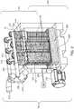
- FIG 2illustrates a perspective view of the fuel cell system 100 shown in Figure 1 .
- the fuel source 108can represent one or more tanks or other containers fuel through the fuel cells in the fuel cell stacks 106.
- the source 108can represent one or more tanks of natural gas or other hydrogen -containing substances.
- the resource 108is fluidly coupled with a fuel input conduit 206 by a fuel supply conduit 200.
- the fuel blower 132is fluidly coupled with the fuel input conduit 206 and a fuel output conduit 204.
- the fuel supply conduit 200carries or directs the source input fuel 110 (shown in Figure 1 ) from the fuel source 108 to the fuel input conduit 206, the fuel input conduit 206 carries the mixed input fuel 134 (shown in Figure 1 ) from the fuel blower 132 to a fuel heat exchanger assembly 202, and the fuel output conduit 204 carries or directs the output fuel 130 from the fuel heat exchanger assembly 202 to the fuel blower 132.
- the heat exchanger assembly 202represents a combination of the low temperature fuel heat exchanger 112 and the high temperature fuel heat exchanger 114 shown in Figure 1 .
- the heat exchangers 112, 114are fluidly coupled with each other and with the conduits 204, 206 such that the low temperature fuel heat exchanger 112 receives the mixed input fuel 134 from the conduit 206, the high temperature fuel heat exchanger 114 receives the heated input fuel 116 from the low temperature heat exchanger 114, the low temperature fuel heat exchanger 112 receives the reduced temperature fuel 128 from the high temperature fuel heat exchanger 114, and the low temperature fuel heat exchanger 112 directs the output fuel 130 into the fuel blower 132 via the conduit 204.
- conduits that fluidly couple the fuel heat exchangersare not visible in Figure 2 , these conduits may resemble the conduits 204, 206 shown in Figure 2 , but disposed within an outer housing 203 of the fuel exchanger assembly 202 (e.g., the portion of the assembly 202 that is visible in Figure 2 ).
- the fuel heat exchanger assembly 202is coupled with housings 107 that contain the fuel cell stacks 106.
- the housings that contain the fuel cell stacks 106may sit directly on top of the heat exchanger assembly 202, as shown in Figure 2 .
- at least part of the outer, external surface of the housings in which the fuel cell stacks 106 are disposedmay directly contact or abut at least part of the outer, external surface of the housing of the fuel heat exchanger assembly 202. This allows the amount of conduit needed to the couple the fuel source 108, the blower 132, the heat exchangers 112, 114, and the fuel cell stacks 106 to be reduced relative to another fuel cell system having one or more of these components disposed farther away from the other components.
- the increased temperature fuel 118is directed out of the fuel heat exchanger assembly 202 and into the fuel cell stacks 106.
- the increased temperature fuel 118is at least partially consumed by the fuel cells in the stacks 106 to generate electric current.
- a portion of the fuel 118 that is not consumed by the fuel cellsis directed into the tail gas oxidizer 122 as the split off fuel 124, and the remainder of the fuel 118 that is not consumed by the fuel cells is directed back into the high temperature fuel heat exchanger 114 in the heat exchanger assembly 202.
- each of the fuel cell stacks 106may include several conduits, with one or more conduits directing some of the fuel leaving the fuel cell stacks 106 into the tail gas oxidizers 122 as the split off fuel 124 and one or more other conduits directing a remainder of the fuel leaving the fuel cell stacks 106 back into the heat exchanger assembly 202, specifically into the high temperature fuel heat exchanger 114, as described above.
- the tail gas oxidizer 122 shown in Figure 1may represent multiple, separate tail gas oxidizers 122, as shown in Figure 2 .
- Each oxidizer 122may sit directly on top of a different fuel cell stack 106, and may separately oxidize the split off fuel 124 coming from that fuel cell stack 106.
- at least part of the outer, external surface of housings 123 in which the tail gas oxidizers 122 are disposedmay directly contact or abut at least part of the outer, external surfaces of the housings of the fuel cell stacks 106.
- the locations of the oxidizers 122 on top of the stacks 106also can reduce the amount and distance of conduit needed to fluidly couple the stacks 106 with the oxidizers 122.
- two or more stacks 106may be coupled with the same oxidizer 122 instead of each fuel cell stack 106 having a separate oxidizer 122.
- the high temperature air heat exchanger 144 shown in Figure 1may represent multiple, separate high temperature air heat exchangers 144, as shown in Figure 2 .
- Each separate high temperature air heat exchanger 144may sit directly on top of a different tail gas oxidizer 122, and may receive the oxidized effluent 150 coming out of the respective tail gas oxidizer 122.
- at least part of the outer, external surface of housings 145 in which the high temperature air heat exchangers 144 are disposedmay directly contact or abut at least part of the outer, external surfaces of the housings of the tail gas oxidizers 122.
- the locations of the high temperature air heat exchangers 144 on top of the tail gas oxidizers 122can reduce the amount and distance of conduit needed to fluidly couple the heat exchangers 144 with the oxidizers 122.
- two or more oxidizers 122may be coupled with the same heat exchanger 144 and/or two or more heat exchangers 144 maybe coupled with the same oxidizer 122.
- the high temperature air heat exchangers 144also are fluidly coupled with the fuel cell stacks 106 in order to supply the input air 146 into the fuel cell stacks 106.
- each of the high temperature air heat exchangers 144includes one or more conduits fluidly coupled with the respective tail gas oxidizer 122 to receive the oxidized effluent 150 and one or more other, separate conduits fluidly coupled with the respective fuel cell stacks 106 to deliver the input air 146 into the fuel cell stack 106.
- the low temperature air heat exchanger 140 shown in Figure 1may represent multiple, separate low temperature air heat exchangers 140, as shown in Figure 2 .
- Each separate low temperature air heat exchanger 140may sit directly on top of a different high temperature air heat exchanger 144, and may receive the output effluent 152 coming out of the respective high temperature air heat exchanger 144.
- at least part of the outer, external surface of housings 141 in which the low temperature air heat exchangers 140 are disposedmay directly contact or abut at least part of the outer, external surfaces of the housings of the high temperature air heat exchangers 144.
- the locations of the low temperature air heat exchangers 140 on top of the high temperature air heat exchangers 144can reduce the amount and distance of conduit needed to fluidly couple the heat exchangers 140, 144 with each other.
- two or more low temperature air heat exchangers 144may be coupled with the same high temperature air heat exchanger 140 and/or two or more high temperature air heat exchangers 140 may be coupled with the same low temperature air heat exchanger 144.
- the low and high temperature air heat exchangers 140, 144are disposed within a single housing as an air heat exchanger assembly, similar to as described above in connection with the fuel heat exchanger assembly 202. Combining the low and high temperature air heat exchangers into a single unit within a single housing and/or combining the low and high temperature fuel heat exchangers into a single unit within a single housing can provide for a simpler, lower cost system.
- keeping the low and high temperature air heat exchangers separate (e.g., in separate housings) and/or keeping the low and high temperature fuel heat exchangers separate (e.g., in separate housings)can allow for the low temperature heat exchangers to be formed from less expensive materials (relative to the high temperature heat exchangers) and can allow for thermal stresses caused by the different amounts of thermal expansion in the heat exchangers to be controlled (e.g., based on the geometric designs of the housings).
- the low temperature air heat exchangers 140are fluidly coupled with an input manifold 210 and an output manifold 208 by several separate conduits 214.
- the input manifold 210is fluidly coupled with an air inlet 212, through which the source air 135 is received into the system 100.
- the source air 135may be obtained from one or more tanks, reservoirs, or the ambient surroundings of the system 100.
- the air blower 136is fluidly coupled with the input manifold 210 to draw and/or push the source air 135 through the input manifold 210 and through the conduits 214 into the low temperature air heat exchangers 140.
- the output manifold 208includes an outlet 216 through which the output air 154 exits the system 100. For example, the output air 154 is directed into the output manifold 208 from the low temperature air heat exchangers 140 via the conduits 214, and exits the system 100 through the outlet 216.
- the positions of the heat exchangers and fuel cell stacksmay differ from those shown in Figure 2 .
- the fuel heat exchanger assembly 202may be disposed on top of the fuel cell stacks 106 and the tail gas oxidizers 122 and air heat exchangers 140, 144 may be below the fuel cell stacks 106.
- the fuel cell stacks 106maybe oriented in another direction (e.g., horizontally as opposed to the vertical orientation shown in Figure 2 ) with the fuel heat exchanger assembly 202 on one side (e.g., the left side or right side) of the fuel cell stacks 106 and the tail gas oxidizers 122 and air heat exchangers 140, 144 on the opposite side (e.g., the right side or left side) of the fuel cell stacks 106.
- the fuel heat exchanger assembly 202on one side (e.g., the left side or right side) of the fuel cell stacks 106 and the tail gas oxidizers 122 and air heat exchangers 140, 144 on the opposite side (e.g., the right side or left side) of the fuel cell stacks 106.
- FIG 3illustrates a flowchart of one embodiment of a method 300 for providing an integrated fuel cell system.
- the method 300may be used to manufacture or create the fuel cell system 100 shown in Figures 1 and 2 in one embodiment.
- a fuel supply conduitis fluidly coupled with a low temperature fuel heat exchanger.
- the fuel supply conduitmay be connected with the low temperature fuel heat exchanger in a location that is between the fuel blower and the low temperature fuel heat exchanger, as described above.
- the housings of the fuel cell stacksare coupled with the housing of the low temperature fuel heat exchanger and a high temperature fuel heat exchanger.
- the fuel cell stacksmay be placed directly on top of the heat exchangers.
- the fuel cell stacksmay include multiple conduits connected with the high temperature fuel heat exchanger. Some of these conduits can be input conduits that direct the increased temperature fuel from the high temperature fuel heat exchanger for partial consumption of the fuel cells to generate electric current. Others of these conduits can be return conduits that direct the heating fuel back into the high temperature fuel heat exchanger, as described above.
- housings of tail gas oxidizersare coupled with the housings of the fuel cell stacks. Conduits inside these housings may fluidly couple the oxidizers with the stacks in order to direct the split off fuel from the stacks into the tail gas oxidizers and to direct the output air from the stacks into the tail gas oxidizers.
- housings of high temperature air heat exchangersare coupled with the housings of the tail gas oxidizers. Conduits inside these housings can fluidly couple the tail gas oxidizers with the high temperature air heat exchangers in order to direct the oxidized effluent from the oxidizers into the high temperature air heat exchangers, as described above.
- housings of the high temperature air heat exchangersare coupled with the housings of the high temperature air heat exchangers. Conduits in these housings can exchange the output effluent from the high temperature air heat exchangers and the heated air from the low temperature air heat exchangers.
- the low temperature air heat exchangersare fluidly coupled with input and output manifolds.
- conduitscan fluidly couple these manifolds with the low temperature air heat exchangers in order to direct the source air into the low temperature air heat exchangers and to direct the output air from the low temperature air heat exchangers out of the fuel cell system.
- the integrated fuel cell system of the inventionincludes one or more fuel cell stacks each including fuel cells configured to generate electric current based on fuel and air supplied to the fuel cells, one or more fuel heat exchangers configured to exchange heat between the fuel supplied to the fuel cells for generating the electric current and a first portion of fuel that is output from the fuel cells, one or more air heat exchangers configured to exchange heat between the air supplied to the fuel cells for generating the electric current and effluent that is output from the fuel cells, and one or more tail gas oxidizers configured to receive a second portion of the fuel that is output from the fuel cells and air that is output from the fuel cells.
- the one or more tail gas oxidizersare configured to oxidize the second portion of the fuel with the effluent that is output from the fuel cells.
- the one or more fuel cell stacksare fluidly coupled with the one or more fuel heat exchangers and the one or more tail gas oxidizers such that the fuel that is output from the fuel cells is split into the first portion that is directed back into the one or more fuel heat exchangers and the second portion that is directed into the one or more tail gas oxidizers.
- the one or more fuel heat exchangerscan be configured to be fluidly coupled with a fuel blower in order to direct all fuel that is output from the one or more heat exchangers back into the one or more fuel heat exchangers via the fuel blower.
- the one or more fuel heat exchangerscan be configured to be fluidly coupled with a fuel source in a location between the fuel blower and the one or more heat exchangers.
- an external housing of the one or more fuel cell stackscan abut an external housing of the one or more fuel heat exchangers.
- an external housing of the one or more tail gas oxidizerscan abut an external housing of the one or more fuel cell stacks.
- an external housing of the one or more air heat exchangerscan abut an external housing of the one or more tail gas oxidizers.
- the one or more tail gas oxidizerscan be disposed between and directly coupled with the one or more fuel cell stacks and the one or more air heat exchangers.
- the one or more fuel heat exchangerscan include a low temperature fuel heat exchanger and a high temperature fuel heat exchanger.
- the low temperature fuel heat exchangercan be disposed between a fuel blower and a fuel source along a fuel flow cycle.
- the high temperature fuel heat exchangercan be disposed between the low temperature fuel heat exchanger and the one or more fuel cell stacks along the fuel flow cycle.
- a method for operating the system of the inventionincludes receiving mixed input source fuel into one or more fuel heat exchangers configured to exchange heat between the mixed input source fuel and a first portion of fuel that is output from fuel cells in one or more fuel cell stacks, generating electric current using the fuel cells in the one or more fuel cell stacks by consuming at least some fuel that is heated by the one or more fuel heat exchangers and at least some air that is heated by one or more air heat exchangers, and directing the first portion of the fuel that is output from the fuel cells into the one or more fuel heat exchangers and a second, remaining portion of the fuel that is output from the fuel cells into one or more tail gas oxidizers.
- the second portion of the fuel that is output from the fuel cellscan be split off from the first portion of the fuel and directed into the one or more tail gas oxidizers in a location between the fuel cells and the one or more fuel heat exchangers.
Landscapes
- Engineering & Computer Science (AREA)
- Chemical & Material Sciences (AREA)
- Life Sciences & Earth Sciences (AREA)
- Sustainable Development (AREA)
- Manufacturing & Machinery (AREA)
- Sustainable Energy (AREA)
- Chemical Kinetics & Catalysis (AREA)
- Electrochemistry (AREA)
- General Chemical & Material Sciences (AREA)
- Combustion & Propulsion (AREA)
- Fuel Cell (AREA)
Description
- The subject matter described herein generally relates to fuel cell systems.
- Fuel cells are electrochemical energy conversion devices that have demonstrated a potential for relatively high efficiency and low pollution in power generation. A fuel cell generally provides a direct current (dc) which may be converted to alternating current (ac) via, for example, an inverter. The dc or ac voltage can be used to power motors, lights, communication equipment and any number of electrical devices and systems. Fuel cells may operate in stationary, semi-stationary, or portable applications. Certain fuel cells, such as SOFCs, may operate in large-scale power systems that provide electricity to satisfy industrial and municipal needs. Others may be useful for smaller portable applications such as, for example, powering cars.
- A fuel cell produces electricity by electrochemically combining a fuel and an oxidant across an ionic conducting layer. This ionic conducting layer, also labeled the electrolyte of the fuel cell, maybe a liquid or solid. Common types of fuel cells include phosphoric acid (PAFC), molten carbonate (MCFC), proton exchange membrane (PEMFC), and solid oxide (SOFC), all generally named after their electrolytes. In practice, fuel cells are typically amassed in electrical series in an assembly of fuel cells to produce power at useful voltages or currents.
- In general, components of a fuel cell include the electrolyte and two electrodes. The reactions that produce electricity generally take place at the electrodes where a catalyst is typically disposed to speed the reactions. The electrodes may be constructed as channels, porous layers, and the like, to increase the surface area for the chemical reactions to occur. The electrolyte carries electrically charged particles from one electrode to the other and is otherwise substantially impermeable to both fuel and oxidant.
- Typically, the fuel cell converts hydrogen (fuel) and oxygen (oxidant) into water (byproduct) to produce electricity. The byproduct water may exit the fuel cell as steam in high-temperature operations. This discharged steam (and other hot exhaust components) may be utilized in turbines and other applications to generate additional electricity or power, providing increased efficiency of power generation. If air is employed as the oxidant, the nitrogen in the air is substantially inert and typically passes through the fuel cell. Hydrogen fuel may be provided via local reforming (e.g., on-site steam reforming) or remote reforming of carbon-based feedstocks, such as reforming of the more readily available natural gas and other hydrocarbon fuels and feedstocks. Examples of hydrocarbon fuels include, but are not limited to, natural gas, methane, ethane, propane, methanol, and other hydrocarbons.
- Fuel cell systems include many components to transfer heat between streams of fuel, to transfer heat between streams of air, and to oxidize the discharged effluent from the fuel cells. These components typically are separate and spatially distributed apart from each other. A significant amount of conduits (e.g., in terms of the number of conduits and/or the total length of the conduits) may be needed to fluidly couple these components. As the amount of conduits needed increases, the amount of heat loss from the fuel and/or air flowing through the conduits increases. As a result, the conduits may need to be fabricated from more thermally insulative (and, therefore, more expensive) materials and/or additional heating components may need to be added to the system. This increases the cost and complexity of the fuel cell systems. See, for example,
WO 2010/044772 . US 2012/034539 A1 discloses a fuel cell system containing fuel cells contacted by hydrogen containing gaseous fuel, generating spent gaseous depleted fuel which is recirculated to a hydrogen separation system, preferably a heat exchanger and condenser to remove water, after which it is mixed with fresh fuel and recirculated to the fuel cells.- Hence, the present invention, as defined by the appended claims, is provided.
- The present inventive subject matter will be better understood from reading the following description of non-limiting embodiments, with reference to the attached drawings, wherein below:
Figure 1 illustrates a flow diagram of one embodiment of an integrated fuel cell system;Figure 2 illustrates a perspective view of the fuel cell system shown inFigure 1 ; andFigure 3 illustrates a flowchart of one embodiment of a method for providing an integrated fuel cell system.- The inventive subject matter described herein provides fuel cell systems that are highly integrated relative to some known fuel cell systems. This integration is permissible due to changes in the paths that fuel and/or air flow within the fuel cell system, which allows for various components of the fuel cell system to be located closer together. This results in fewer and shorter conduits being needed to fluidly couple components of the fuel cell system. Consequently, less heat loss in the fuel and/or air flowing through the fuel cell system occurs, and the cost and complexity of the fuel cell system is decreased (relative to some other fuel cell systems).
Figure 1 illustrates a flow diagram of one embodiment of afuel cell system 100. Operation and components of the fuel cell system are described in connection with how fuel and air flow through thefuel cell system 100. Fuel flows in thefuel cell system 100 along or in afuel flow cycle 102 and air flows in the fuel cell system along or in anairflow cycle 104. Theflow cycles fuel cell system 100 in order to be heated, exchange heat, and be provided to one or more stacks offuel cells 106 in order to generate electric current. Thefuel cells 106 can represent one or more stacks of fuel cells, such as SOFC or another type of fuel cell.- With respect to the
fuel cell cycle 102, fuel is input into thefuel cell system 100 from asource 108 of the fuel ("Fuel Source" inFigure 1 ). Thissource 108 can represent one or more containers of a hydrogen-containing substance, such as natural gas. The fuel provided by thesource 108 and input into thefuel cell system 100 may be referred to assource input fuel 110. Theinput fuel 110 is mixed withoutput fuel 130 exiting from afuel blower 132 to form mixedinput fuel 134, as described in more detail below. - The mixed
input fuel 134 is received into a low temperature fuel heat exchanger 112 ("FF LT" inFigure 1 ). In the low temperaturefuel heat exchanger 112, the mixedinput fuel 134 is heated. The mixedinput fuel 134 receives heat from theoutput fuel 130 in the low temperaturefuel heat exchanger 112, which is fuel output by a high temperature heat exchanger 114 ("FF HT" inFigure 1 ). In one embodiment, the temperature of the mixedinput fuel 134 may be increased by the low temperaturefuel heat exchanger 112 such that the temperature of the mixedinput fuel 134 is at least doubled. For example, the temperature of the mixedinput fuel 134 may be increased from a temperature of around 190°C to temperature in excess of 500°C, such as such as 520°C. The mixedinput fuel 134 is heated and output from the low temperaturefuel heat exchanger 112 as heatedinput fuel 116. - This heated
input fuel 116 is then received into the high temperaturefuel heat exchanger 114. The high temperaturefuel heat exchanger 114 increases the temperature of the heatedinput fuel 116 from thermal energy in heatingfuel 126 that is received by the high temperaturefuel heat exchanger 114 from the fuel cell stacks 106 (described in more detail below). Similar to the low temperaturefuel heat exchanger 112, the high temperaturefuel heat exchanger 114 transfers heat (e.g., thermal energy) from thehotter heating fuel 126 to the cooler heatedinput fuel 116. The temperature of the heatedinput fuel 116 is increased in the high temperaturefuel heat exchanger 114 and output as increasedtemperature fuel 118. - In one embodiment, the increase in temperature of the heated
input fuel 116 to the increasedtemperature fuel 118 is less than the increase in temperature from the mixedinput fuel 134 to the heatedinput fuel 116. For example, the low temperaturefuel heat exchanger 112 may more than double the temperature of the mixedinput fuel 134 while the high temperaturefuel heat exchanger 114 increases the temperature of the heatedinput fuel 116 by a lesser amount. The high temperaturefuel heat exchanger 114 can increase the heatedinput fuel 116 from a temperature of about 520°C to a temperature of the increasedtemperature fuel 118 that is at least 700°C, such as 702°C. - The increased
temperature fuel 118 that is output from the high temperaturefuel heat exchanger 114 is directed to the one or morefuel cell stacks 106. The fuel cells in thestacks 106 consume at least part of this increasedtemperature fuel 118 in the generation of electric current. The fuel that is not consumed by thefuel cell stacks 106 is output from thefuel cell stacks 106 asoutput fuel 120. Theoutput fuel 120 may have an increased temperature relative to the increasedtemperature fuel 118 is input into thefuel cell stacks 106. For example, the temperature of theoutput fuel 120 may be in excess of 800°C, such as 808°C, while the temperature of the increasedtemperature fuel 118 may be 700°C or another temperature. - According to the invention, part of the
output fuel 120 from thefuel cell stacks 106 is split off from thefuel cycle 102 as split offfuel 124. For example, the conduit carrying theoutput fuel 120 from the fuel cell stacks 106 may split into two or more separate conduits, with one or more conduits carrying the split offfuel 124 into theair flow cycle 104 and one or more other conduits carrying the remainingoutput fuel 120 to the high temperaturefuel heat exchanger 114 as theheating fuel 126. In one embodiment, the portion of theoutput fuel 120 split off or separated from thefuel cycle 102 as the split offfuel 124 can be 20% of theoutput fuel 120. For example, 20% of the mass of theoutput fuel 120 may be directed into theair flow cycle 104 as the split offfuel 124. - The
heating fuel 126 is input into the high temperaturefuel heat exchanger 114. Thisheating fuel 126 exchanges heat with theinput fuel 116 in theheat exchanger 114. Heat is transferred from theheating fuel 126 to theinput fuel 116 in order to increase the temperature of theinput fuel 116 to the temperature of the increasedtemperature fuel 118 that is output by the high temperaturefuel heat exchanger 114. Theheating fuel 126 is cooled by the high temperaturefuel heat exchanger 114 and is output from the high temperaturefuel heat exchanger 114 as reducedtemperature fuel 128. In one embodiment, the temperature of theheating fuel 126 may be reduced by the high temperaturefuel heat exchanger 114 by at least 200°C. For example, the temperature of theheating fuel 126 may be in excess of 800°C (for example, a temperature of 802°C) while the temperature of the reducedtemperature fuel 128 may be below 680 °C. - The reduced
temperature fuel 128 is output from the high temperaturefuel heat exchanger 114 and is input into the low temperaturefuel heat exchanger 112, as shown inFigure 1 . The low temperaturefuel heat exchanger 112 exchanges thermal energy from the reducedtemperature fuel 128 to themixed input fuel 134. This cools the reducedtemperature fuel 128 and heats up themixed input fuel 134. For example, the temperature of the reducedtemperature fuel 128 may be reduced (for example, to 200°C) by transferring thermal energy to themixed input fuel 134. This increases the temperature of themixed input fuel 134 to the temperature of theinput fuel 116. - The reduced
temperature fuel 128 is cooled and output from the low temperaturefuel heat exchanger 112 as theoutput fuel 130. Theoutput fuel 130 is recirculated into thefuel flow cycle 102 by theblower 132, which can represent a fan or other device that moves the fuel through thefuel flow cycle 102. Theoutput fuel 130 passes through theblower 132 to keep the fuel moving within thefuel flow cycle 102. Theblower 132 may increase the temperature of theoutput fuel 130, such as by increasing temperature of theoutput fuel 130 from 200°C to 230°C, as one example. As described above, theoutput fuel 130 is missed with thesource input fuel 110 to form themixed input fuel 134 in thefuel flow cycle 102. - In one embodiment, all of the
output fuel 130 that is received into thefuel blower 132 is directed into the low temperaturefuel heat exchanger 112. Thisoutput fuel 130 can be mixed with additionalsource input fuel 110, but no part of theoutput fuel 130 received into thefuel blower 132 from the low temperaturefuel heat exchanger 112 is split off or directed elsewhere other than back into the low temperaturefuel heat exchanger 112. - With respect to the
air flow cycle 104 of thefuel cell system 100,source air 135 is drawn into thefuel cell system 100 by ablower 136. Thisair 135 may be obtained from an oxygen tank or may be ambient air drawn into thefuel cell system 100 from outside of thefuel cell system 100. Theair 135 output by theblower 136 can be referred to asinput air 138. - The
input air 138 is directed into a low temperature air heat exchanger 140 ("AA LT" inFigure 1 ). Similar to as described above with the low temperaturefuel heat exchanger 112, the low temperatureair heat exchanger 140 increases the temperature of theinput air 138 and outputs the air asheated air 140. In one embodiment, the temperature of theinput air 138 is or is about 90°C, and the temperature of theheated air 140 is at least 500°C, such as 520°C. Theheated air 142 is input into a high temperature air heat exchanger 144 ("AA HT" inFigure 1 ) and is heated from heat of oxidized effluent 150 (described below). For example, the high temperatureair heat exchanger 144 can increase the temperature of theheated air 142 at least 100°C and up to 200°C (or another temperature). In one embodiment, the high temperatureair heat exchanger 144 increases the temperature of theair 142 from 520°C to a temperature of about 700°C. The high temperatureair heat exchanger 144 heats theair 142 intoinput air 146 that is output by theheat exchanger 144. - The
input air 146 is directed into the fuel cell stacks 106 for at least partial consumption by the fuel cells. As described above, thefuel cells 106 consume at least some of thefuel 118 andair 146 to generate electric current. In one embodiment, fuel cell may generate significant amounts of electric current, such as 270 kW of electric energy. In addition to theoutput fuel 120 that is output from the fuel cell stacks 106, the fuel cell stacks 106 alsodirect output air 148 out of the fuel cell stacks 106. Theoutput air 148 is directed into thetail gas oxidizer 122 along with the split offfuel 124, as described above. Theoutput air 148 is effluent that is output by the fuel cells. As shown inFigure 1 , all of the air that is output by the fuel cells may be directed into thetail gas oxidizer 122. - The
tail gas oxidizer 122 oxidizes the split offfuel 124 using at least some of theoutput air 148. The oxidized fuel is output from thetail gas oxidizer 122 as the oxidizedeffluent 150. The oxidizedeffluent 150 may have an elevated temperature, such as the temperature of 850°C or another temperature. The oxidizedeffluent 150 is received into the high temperatureair heat exchanger 144, where the effluent 150 heats theheated air 142 into theinput air 146, as described above. In one embodiment, passage of the oxidizedeffluent 150 through the high temperatureair heat exchanger 144 reduces the temperature of theeffluent 150 by at least 200°C. For example, the temperature of the oxidizedeffluent 150 may be reduced from a temperature of 850°C to a temperature such as 630°C, or 632°C. - The
effluent 150 exits the hightemperature heat exchanger 144 asoutput effluent 152. The low temperatureair heat exchanger 140 receives theoutput effluent 152 and transfers thermal energy from theoutput effluent 152 to theinput air 138, as described above. This can reduce the temperature of theoutput effluent 152 from a temperature in excess of 600°C to a temperature of no more than 250°C. Theoutput effluent 152 exits the low temperature air heat exchanger asoutput air 154, which exits the air flow cycle 104 (as shown inFigure 1 ). - One difference between the fuel and air flow cycles 102, 104 in the
fuel cell system 100 and other fuel cell systems is the location of where fuel is split off from the fuel flow cycle into the tail gas oxidizer. Some known fuel cell systems split off the fuel from the fuel flow cycle in a location that would be between thefuel blower 132 and the low temperaturefuel heat exchanger 112. Because thefuel blower 132 and the low temperaturefuel heat exchanger 112 may not be located close to thetail gas oxidizer 122 in these systems, splitting off the fuel in this location can require a significant amount (e.g., length) of conduits. This can increase the cost and complexity of the system. - In the illustrated embodiment of the
fuel cell system 100, however, the fuel splits off from thefuel flow cycle 102 in a location between the fuel cell stacks 106 and the tail gas oxidizer 122 (e.g., downstream of the fuel cell stacks 106 and upstream of thetail gas oxidizer 122 in the direction of fuel flow in the fuel flow cycle 102). Thefuel 124 is split off from thefuel flow cycle 102 in this location, without any other components (e.g., any other heat exchangers, blowers, etc.) being located between the fuel cell stacks 106 and theoxidizer 122. Because the fuel cell stacks 106 are directly coupled with theoxidizer 122 without any heat exchangers, blowers, etc., located between the fuel cell stacks 106 and theoxidizer 122, the fuel can be split off in this location without passing through any other components prior to the split off. - Another difference between some known fuel cell systems is that the
fuel cell system 100 directs theoutput air 148 from the fuel cell stacks 106 directly into theoxidizer 122 for oxidizing the split offfuel 124. Theoxidizer 122 can be close to the fuel cell stacks 106 to allow for this flow path of theoutput air 148 and to avoid a requirement for a significant distance of conduits to direct theoutput air 148 into theoxidizer 122. Additionally, the oxidizedeffluent 150 from theoxidizer 122 can be directed directly into the high temperatureair heat exchanger 144 without the oxidizedeffluent 150 passing through any other components or mixing with any other fluids (e.g., without mixing with theair 148 that is output from the fuel cell stacks 106. Figure 2 illustrates a perspective view of thefuel cell system 100 shown inFigure 1 . Thefuel source 108 can represent one or more tanks or other containers fuel through the fuel cells in the fuel cell stacks 106. For example, thesource 108 can represent one or more tanks of natural gas or other hydrogen -containing substances. Theresource 108 is fluidly coupled with afuel input conduit 206 by afuel supply conduit 200.- The
fuel blower 132 is fluidly coupled with thefuel input conduit 206 and a fuel output conduit 204. Thefuel supply conduit 200 carries or directs the source input fuel 110 (shown inFigure 1 ) from thefuel source 108 to thefuel input conduit 206, thefuel input conduit 206 carries the mixed input fuel 134 (shown inFigure 1 ) from thefuel blower 132 to a fuelheat exchanger assembly 202, and the fuel output conduit 204 carries or directs theoutput fuel 130 from the fuelheat exchanger assembly 202 to thefuel blower 132. - The
heat exchanger assembly 202 represents a combination of the low temperaturefuel heat exchanger 112 and the high temperaturefuel heat exchanger 114 shown inFigure 1 . Theheat exchangers conduits 204, 206 such that the low temperaturefuel heat exchanger 112 receives themixed input fuel 134 from theconduit 206, the high temperaturefuel heat exchanger 114 receives theheated input fuel 116 from the lowtemperature heat exchanger 114, the low temperaturefuel heat exchanger 112 receives the reducedtemperature fuel 128 from the high temperaturefuel heat exchanger 114, and the low temperaturefuel heat exchanger 112 directs theoutput fuel 130 into thefuel blower 132 via the conduit 204. Although the conduits that fluidly couple the fuel heat exchangers are not visible inFigure 2 , these conduits may resemble theconduits 204, 206 shown inFigure 2 , but disposed within anouter housing 203 of the fuel exchanger assembly 202 (e.g., the portion of theassembly 202 that is visible inFigure 2 ). - The fuel
heat exchanger assembly 202 is coupled withhousings 107 that contain the fuel cell stacks 106. The housings that contain the fuel cell stacks 106 may sit directly on top of theheat exchanger assembly 202, as shown inFigure 2 . For example, at least part of the outer, external surface of the housings in which the fuel cell stacks 106 are disposed may directly contact or abut at least part of the outer, external surface of the housing of the fuelheat exchanger assembly 202. This allows the amount of conduit needed to the couple thefuel source 108, theblower 132, theheat exchangers - The increased
temperature fuel 118 is directed out of the fuelheat exchanger assembly 202 and into the fuel cell stacks 106. The increasedtemperature fuel 118 is at least partially consumed by the fuel cells in thestacks 106 to generate electric current. A portion of thefuel 118 that is not consumed by the fuel cells is directed into thetail gas oxidizer 122 as the split offfuel 124, and the remainder of thefuel 118 that is not consumed by the fuel cells is directed back into the high temperaturefuel heat exchanger 114 in theheat exchanger assembly 202. - For example, although not visible in
Figure 2 , each of the fuel cell stacks 106 may include several conduits, with one or more conduits directing some of the fuel leaving the fuel cell stacks 106 into thetail gas oxidizers 122 as the split offfuel 124 and one or more other conduits directing a remainder of the fuel leaving the fuel cell stacks 106 back into theheat exchanger assembly 202, specifically into the high temperaturefuel heat exchanger 114, as described above. - The
tail gas oxidizer 122 shown inFigure 1 may represent multiple, separatetail gas oxidizers 122, as shown inFigure 2 . Eachoxidizer 122 may sit directly on top of a differentfuel cell stack 106, and may separately oxidize the split offfuel 124 coming from thatfuel cell stack 106. For example, at least part of the outer, external surface ofhousings 123 in which thetail gas oxidizers 122 are disposed may directly contact or abut at least part of the outer, external surfaces of the housings of the fuel cell stacks 106. The locations of theoxidizers 122 on top of thestacks 106 also can reduce the amount and distance of conduit needed to fluidly couple thestacks 106 with theoxidizers 122. Optionally, two ormore stacks 106 may be coupled with thesame oxidizer 122 instead of eachfuel cell stack 106 having aseparate oxidizer 122. - The high temperature
air heat exchanger 144 shown inFigure 1 may represent multiple, separate high temperatureair heat exchangers 144, as shown inFigure 2 . Each separate high temperatureair heat exchanger 144 may sit directly on top of a differenttail gas oxidizer 122, and may receive the oxidizedeffluent 150 coming out of the respectivetail gas oxidizer 122. For example, at least part of the outer, external surface ofhousings 145 in which the high temperatureair heat exchangers 144 are disposed may directly contact or abut at least part of the outer, external surfaces of the housings of thetail gas oxidizers 122. The locations of the high temperatureair heat exchangers 144 on top of thetail gas oxidizers 122 can reduce the amount and distance of conduit needed to fluidly couple theheat exchangers 144 with theoxidizers 122. Optionally, two ormore oxidizers 122 may be coupled with thesame heat exchanger 144 and/or two ormore heat exchangers 144 maybe coupled with thesame oxidizer 122. - The high temperature
air heat exchangers 144 also are fluidly coupled with the fuel cell stacks 106 in order to supply theinput air 146 into the fuel cell stacks 106. In one embodiment, each of the high temperatureair heat exchangers 144 includes one or more conduits fluidly coupled with the respectivetail gas oxidizer 122 to receive the oxidizedeffluent 150 and one or more other, separate conduits fluidly coupled with the respective fuel cell stacks 106 to deliver theinput air 146 into thefuel cell stack 106. - The low temperature
air heat exchanger 140 shown inFigure 1 may represent multiple, separate low temperatureair heat exchangers 140, as shown inFigure 2 . Each separate low temperatureair heat exchanger 140 may sit directly on top of a different high temperatureair heat exchanger 144, and may receive theoutput effluent 152 coming out of the respective high temperatureair heat exchanger 144. For example, at least part of the outer, external surface ofhousings 141 in which the low temperatureair heat exchangers 140 are disposed may directly contact or abut at least part of the outer, external surfaces of the housings of the high temperatureair heat exchangers 144. - The locations of the low temperature
air heat exchangers 140 on top of the high temperatureair heat exchangers 144 can reduce the amount and distance of conduit needed to fluidly couple theheat exchangers air heat exchangers 144 may be coupled with the same high temperatureair heat exchanger 140 and/or two or more high temperatureair heat exchangers 140 may be coupled with the same low temperatureair heat exchanger 144. - In one embodiment, the low and high temperature
air heat exchangers heat exchanger assembly 202. Combining the low and high temperature air heat exchangers into a single unit within a single housing and/or combining the low and high temperature fuel heat exchangers into a single unit within a single housing can provide for a simpler, lower cost system. But, keeping the low and high temperature air heat exchangers separate (e.g., in separate housings) and/or keeping the low and high temperature fuel heat exchangers separate (e.g., in separate housings) can allow for the low temperature heat exchangers to be formed from less expensive materials (relative to the high temperature heat exchangers) and can allow for thermal stresses caused by the different amounts of thermal expansion in the heat exchangers to be controlled (e.g., based on the geometric designs of the housings). - The low temperature
air heat exchangers 140 are fluidly coupled with aninput manifold 210 and anoutput manifold 208 by severalseparate conduits 214. Theinput manifold 210 is fluidly coupled with anair inlet 212, through which thesource air 135 is received into thesystem 100. Thesource air 135 may be obtained from one or more tanks, reservoirs, or the ambient surroundings of thesystem 100. Theair blower 136 is fluidly coupled with theinput manifold 210 to draw and/or push thesource air 135 through theinput manifold 210 and through theconduits 214 into the low temperatureair heat exchangers 140. Theoutput manifold 208 includes anoutlet 216 through which theoutput air 154 exits thesystem 100. For example, theoutput air 154 is directed into theoutput manifold 208 from the low temperatureair heat exchangers 140 via theconduits 214, and exits thesystem 100 through theoutlet 216. - The positions of the heat exchangers and fuel cell stacks may differ from those shown in
Figure 2 . For example, the fuelheat exchanger assembly 202 may be disposed on top of the fuel cell stacks 106 and thetail gas oxidizers 122 andair heat exchangers Figure 2 ) with the fuelheat exchanger assembly 202 on one side (e.g., the left side or right side) of the fuel cell stacks 106 and thetail gas oxidizers 122 andair heat exchangers Figure 3 illustrates a flowchart of one embodiment of amethod 300 for providing an integrated fuel cell system. Themethod 300 may be used to manufacture or create thefuel cell system 100 shown inFigures 1 and2 in one embodiment. At 302, a fuel supply conduit is fluidly coupled with a low temperature fuel heat exchanger. The fuel supply conduit may be connected with the low temperature fuel heat exchanger in a location that is between the fuel blower and the low temperature fuel heat exchanger, as described above.- At 304, the housings of the fuel cell stacks are coupled with the housing of the low temperature fuel heat exchanger and a high temperature fuel heat exchanger. The fuel cell stacks may be placed directly on top of the heat exchangers. The fuel cell stacks may include multiple conduits connected with the high temperature fuel heat exchanger. Some of these conduits can be input conduits that direct the increased temperature fuel from the high temperature fuel heat exchanger for partial consumption of the fuel cells to generate electric current. Others of these conduits can be return conduits that direct the heating fuel back into the high temperature fuel heat exchanger, as described above.
- At 306, housings of tail gas oxidizers are coupled with the housings of the fuel cell stacks. Conduits inside these housings may fluidly couple the oxidizers with the stacks in order to direct the split off fuel from the stacks into the tail gas oxidizers and to direct the output air from the stacks into the tail gas oxidizers.
- At 308, housings of high temperature air heat exchangers are coupled with the housings of the tail gas oxidizers. Conduits inside these housings can fluidly couple the tail gas oxidizers with the high temperature air heat exchangers in order to direct the oxidized effluent from the oxidizers into the high temperature air heat exchangers, as described above.
- At 310, housings of the high temperature air heat exchangers are coupled with the housings of the high temperature air heat exchangers. Conduits in these housings can exchange the output effluent from the high temperature air heat exchangers and the heated air from the low temperature air heat exchangers.
- At 312, the low temperature air heat exchangers are fluidly coupled with input and output manifolds. As described above, conduits can fluidly couple these manifolds with the low temperature air heat exchangers in order to direct the source air into the low temperature air heat exchangers and to direct the output air from the low temperature air heat exchangers out of the fuel cell system.
- The integrated fuel cell system of the invention is defined in the appended claims and includes one or more fuel cell stacks each including fuel cells configured to generate electric current based on fuel and air supplied to the fuel cells, one or more fuel heat exchangers configured to exchange heat between the fuel supplied to the fuel cells for generating the electric current and a first portion of fuel that is output from the fuel cells, one or more air heat exchangers configured to exchange heat between the air supplied to the fuel cells for generating the electric current and effluent that is output from the fuel cells, and one or more tail gas oxidizers configured to receive a second portion of the fuel that is output from the fuel cells and air that is output from the fuel cells. The one or more tail gas oxidizers are configured to oxidize the second portion of the fuel with the effluent that is output from the fuel cells. The one or more fuel cell stacks are fluidly coupled with the one or more fuel heat exchangers and the one or more tail gas oxidizers such that the fuel that is output from the fuel cells is split into the first portion that is directed back into the one or more fuel heat exchangers and the second portion that is directed into the one or more tail gas oxidizers.
- In one example, the one or more fuel heat exchangers can be configured to be fluidly coupled with a fuel blower in order to direct all fuel that is output from the one or more heat exchangers back into the one or more fuel heat exchangers via the fuel blower.
- In one example, the one or more fuel heat exchangers can be configured to be fluidly coupled with a fuel source in a location between the fuel blower and the one or more heat exchangers.
- In one example, an external housing of the one or more fuel cell stacks can abut an external housing of the one or more fuel heat exchangers.
- In one example, an external housing of the one or more tail gas oxidizers can abut an external housing of the one or more fuel cell stacks.
- In one example, an external housing of the one or more air heat exchangers can abut an external housing of the one or more tail gas oxidizers.
- In one example, the one or more tail gas oxidizers can be disposed between and directly coupled with the one or more fuel cell stacks and the one or more air heat exchangers.
- In one example, the one or more fuel heat exchangers can include a low temperature fuel heat exchanger and a high temperature fuel heat exchanger. The low temperature fuel heat exchanger can be disposed between a fuel blower and a fuel source along a fuel flow cycle. The high temperature fuel heat exchanger can be disposed between the low temperature fuel heat exchanger and the one or more fuel cell stacks along the fuel flow cycle.
- In one embodiment, a method for operating the system of the invention includes receiving mixed input source fuel into one or more fuel heat exchangers configured to exchange heat between the mixed input source fuel and a first portion of fuel that is output from fuel cells in one or more fuel cell stacks, generating electric current using the fuel cells in the one or more fuel cell stacks by consuming at least some fuel that is heated by the one or more fuel heat exchangers and at least some air that is heated by one or more air heat exchangers, and directing the first portion of the fuel that is output from the fuel cells into the one or more fuel heat exchangers and a second, remaining portion of the fuel that is output from the fuel cells into one or more tail gas oxidizers.
- In one example, the second portion of the fuel that is output from the fuel cells can be split off from the first portion of the fuel and directed into the one or more tail gas oxidizers in a location between the fuel cells and the one or more fuel heat exchangers.
- As used herein, an element or step recited in the singular and proceeded with the word "a" or "an" should be understood as not excluding plural of said elements or steps, unless such exclusion is explicitly stated. Furthermore, references to "one embodiment" of the presently described subject matter are not intended to be interpreted as excluding the existence of additional embodiments that also incorporate the recited features. Moreover, unless explicitly stated to the contrary, embodiments "comprising" or "having" an element or a plurality of elements having a particular property may include additional such elements not having that property.
- It is to be understood that the above description is intended to be illustrative, and not restrictive. For example, the above-described embodiments (and/or aspects thereof) may be used in combination with each other. While the dimensions and types of materials described herein are intended to define the parameters of the disclosed subject matter, they are by no means limiting and are exemplary embodiments. Many other embodiments will be apparent to those of skill in the art upon reviewing the above description. The scope of the subject matter described herein should be determined with reference to the appended claims.
- In the appended claims, the terms "including" and "in which" are used as the plain-English equivalents of the respective terms "comprising" and "wherein." Moreover, in the following claims, the terms "first," "second," and "third," etc. are used merely as labels, and are not intended to impose numerical requirements on their objects.
- This written description uses examples to disclose several embodiments of the subject matter set forth herein, including the preferred mode, and also to enable a person of ordinary skill in the art to practice the embodiments of disclosed subject matter, including making and using the devices or systems and performing the methods. The patentable scope of the subject matter described herein is defined by the claims, and may include other examples that occur to those of ordinary skill in the art.
Claims (10)
- A system (100) comprising:one or more fuel cell stacks each including fuel cells (106) configured to generate electric current based on fuel (116) and air (142) supplied to the fuel cells;one or more fuel heat exchangers (112) configured to exchange heat between the fuel supplied to the fuel cells for generating the electric current and a first portion of fuel that is output from the fuel cells;one or more tail gas oxidizers (122) configured to receive a second portion of the fuel that is output from the fuel cells and air (148) that is output from the fuel cells, the one or more tail gas oxidizers configured to oxidize the second portion of the fuel with the effluent that is output from the fuel cells, so as to output an oxidized effluent (150); andone or more air heat exchangers (144) configured to exchange heat between the air supplied to the fuel cells for generating the electric current and the oxidised effluent,wherein the one or more fuel cell stacks (106) are fluidly coupled with the one or more fuel heat exchangers (112) and the one or more tail gas oxidizers such that the fuel that is output from the fuel cells is split into the first portion that is directed back into the one or more fuel heat exchangers and the second portion that is directed into the one or more tail gas oxidizers;characterized in that:i) the one or more fuel cell stacks (106) are disposed between and directly coupled with the one or more fuel heat exchangers and the one or more tail gas oxidizers; orii) the one or more fuel heat exchangers (112) are coupled to one end of the one or more fuel cell stacks (106) and the one or more tail gas oxidizers and the one or more air heat exchangers are coupled to an opposite end of the one or more fuel cell stacks, wherein the one or more tail gas oxidisers are directly coupled to the one or more fuel cell stacks.
- The system (100) of claim 1, wherein the one or more fuel heat exchangers (112) are configured to be fluidly coupled with a fuel blower in order to direct all fuel that is output from the one or more heat exchangers back into the one or more fuel heat exchangers via the fuel blower.
- The system (100) of any of preceding claim, wherein the one or more fuel heat exchangers (112) are configured to be fluidly coupled with a fuel source in a location between the fuel blower and the one or more heat exchangers.
- The system (100) of any preceding claim, wherein an external housing of the one or more fuel cell stacks abuts an external housing of the one or more fuel heat exchangers.
- The system (100) of any preceding claim, wherein an external housing of the one or more tail gas oxidizers (122) abuts an external housing of the one or more fuel cell stacks.
- The system (100) of any preceding claim, wherein an external housing of the one or more air heat exchangers (144) abuts an external housing of the one or more tail gas oxidizers (122).
- The system (100) of any preceding claim, wherein the one or more tail gas oxidizers (122) are disposed between and directly coupled with the one or more fuel cell stacks (106) and the one or more air heat exchangers (144).
- The system (100) of any preceding claim, wherein the one or more fuel heat exchangers (112) include a low temperature fuel heat exchanger and a high temperature fuel heat exchanger, the low temperature fuel heat exchanger disposed between a fuel blower (132) and a fuel source along a fuel flow cycle, the high temperature fuel heat exchanger disposed between the low temperature fuel heat exchanger and the one or more fuel cell stacks along the fuel flow cycle.
- A method for operating the system (100) of any preceding claim, comprising:receiving mixed input source fuel into one or more fuel heat exchangers (112) configured to exchange heat between the mixed input source fuel and a first portion of fuel that is output from fuel cells in one or more fuel cell stacks (106);generating electric current using the fuel cells (106) in the one or more fuel cell stacks by consuming at least some fuel that is heated by the one or more fuel heat exchangers (112) and at least some air that is heated by one or more air heat exchangers (144); anddirecting the first portion of the fuel that is output from the fuel cells (106) into the one or more fuel heat exchangers (112) and a second, remaining portion of the fuel that is output from the fuel cells into one or more tail gas oxidizers (122).
- The method of claim 9, wherein the second portion of the fuel that is output from the fuel cells (106) is split off from the first portion of the fuel and directed into the one or more tail gas oxidizers (122) in a location between the fuel cells (106) and the one or more fuel heat exchangers (112).
Applications Claiming Priority (1)
| Application Number | Priority Date | Filing Date | Title |
|---|---|---|---|
| US15/263,505US10347924B2 (en) | 2016-09-13 | 2016-09-13 | Integrated fuel cell systems |
Publications (2)
| Publication Number | Publication Date |
|---|---|
| EP3293803A1 EP3293803A1 (en) | 2018-03-14 |
| EP3293803B1true EP3293803B1 (en) | 2021-11-03 |
Family
ID=59790993
Family Applications (1)
| Application Number | Title | Priority Date | Filing Date |
|---|---|---|---|
| EP17189359.7AActiveEP3293803B1 (en) | 2016-09-13 | 2017-09-05 | Integrated fuel cell systems |
Country Status (6)
| Country | Link |
|---|---|
| US (2) | US10347924B2 (en) |
| EP (1) | EP3293803B1 (en) |
| JP (1) | JP7158137B2 (en) |
| KR (1) | KR102490704B1 (en) |
| CN (1) | CN107819141B (en) |
| ES (1) | ES2901489T3 (en) |
Families Citing this family (10)
| Publication number | Priority date | Publication date | Assignee | Title |
|---|---|---|---|---|
| US12261747B2 (en) | 2019-09-20 | 2025-03-25 | Sonatus, Inc. | System, method, and apparatus to execute vehicle communications using a zonal architecture |
| JP7310613B2 (en)* | 2020-01-06 | 2023-07-19 | 株式会社Ihi | fuel cell system |
| JP7483598B2 (en)* | 2020-12-10 | 2024-05-15 | 日産自動車株式会社 | Fuel Cell Systems |
| KR102602831B1 (en)* | 2021-04-02 | 2023-11-16 | 한국기계연구원 | Hybrid system of fuel cell |
| DE102021214807A1 (en)* | 2021-12-21 | 2023-06-22 | Robert Bosch Gesellschaft mit beschränkter Haftung | fuel cell device |
| CN114312368A (en)* | 2021-12-30 | 2022-04-12 | 潍柴动力股份有限公司 | A fuel cell system and hydrogen fuel cell bus |
| KR20240160522A (en) | 2023-05-02 | 2024-11-11 | 피엔피에너지텍 주식회사 | SOFC System Including Catalytic Burner with Heat Exchanger Structure |
| KR20240160523A (en) | 2023-05-02 | 2024-11-11 | 피엔피에너지텍 주식회사 | SOFC System Including Reformer with Heat Exchanger Structure |
| KR20250007994A (en) | 2023-07-06 | 2025-01-14 | 피엔피에너지텍 주식회사 | SOFC System with Multi-functional BOP Components and Operating Method thereof |
| KR20250024730A (en) | 2023-08-09 | 2025-02-19 | 피엔피에너지텍 주식회사 | Recycling blower for fuel cell system and SOFC System including the same |
Family Cites Families (27)
| Publication number | Priority date | Publication date | Assignee | Title |
|---|---|---|---|---|
| US5340664A (en) | 1993-09-29 | 1994-08-23 | Ceramatec, Inc. | Thermally integrated heat exchange system for solid oxide electrolyte systems |
| JP2001052727A (en)* | 1999-08-04 | 2001-02-23 | Mitsubishi Heavy Ind Ltd | Power generating system by fuel cell |
| CN1514802A (en) | 2001-04-18 | 2004-07-21 | ��ʿ�ŷ�չ��˾ | Integrated fuel processing machine, fuel cell stack and tail gas oxidizer with carbon dioxide removal |
| US6670062B2 (en) | 2001-05-31 | 2003-12-30 | Plug Power Inc. | Methods and systems for humidifying fuel for use in fuel processors and fuel cell systems |
| GB0213561D0 (en) | 2002-06-13 | 2002-07-24 | Alstom | Fuel cells |
| JP2004103282A (en) | 2002-09-05 | 2004-04-02 | Mitsubishi Heavy Ind Ltd | Solid oxide fuel cell power generation system |
| US6924053B2 (en) | 2003-03-24 | 2005-08-02 | Ion America Corporation | Solid oxide regenerative fuel cell with selective anode tail gas circulation |
| JP4831947B2 (en)* | 2004-09-01 | 2011-12-07 | 東京瓦斯株式会社 | Fuel cell cogeneration system |
| US7709118B2 (en) | 2004-11-18 | 2010-05-04 | Siemens Energy, Inc. | Recuperated atmospheric SOFC/gas turbine hybrid cycle |
| US8920997B2 (en) | 2007-07-26 | 2014-12-30 | Bloom Energy Corporation | Hybrid fuel heat exchanger—pre-reformer in SOFC systems |
| US8288041B2 (en) | 2008-02-19 | 2012-10-16 | Bloom Energy Corporation | Fuel cell system containing anode tail gas oxidizer and hybrid heat exchanger/reformer |
| US20090208785A1 (en) | 2008-02-20 | 2009-08-20 | Bloom Energy Cororation | SOFC electrochemical anode tail gas oxidizer |
| WO2009149314A2 (en) | 2008-06-06 | 2009-12-10 | Fuelcell Energy, Inc. | Modular fuel cell stack assembly including anode gas oxidizer and integrated external manifolds for use in fuel cell stack modules |
| WO2010044772A1 (en) | 2008-10-14 | 2010-04-22 | Utc Power Corporation | Solid oxide fuel cell with anode exhaust recycle |
| WO2011028808A2 (en)* | 2009-09-02 | 2011-03-10 | Bloom Energy Corporation | Multi-stream heat exchanger for a fuel cell system |
| JP5504018B2 (en)* | 2010-03-15 | 2014-05-28 | 本田技研工業株式会社 | Fuel cell stack |
| US20120034539A1 (en) | 2010-08-04 | 2012-02-09 | Raymond George | High efficiency and reliable fuel cell system operating at near 100% fuel utilization |
| US8563180B2 (en)* | 2011-01-06 | 2013-10-22 | Bloom Energy Corporation | SOFC hot box components |
| JP5779371B2 (en) | 2011-03-18 | 2015-09-16 | 川崎重工業株式会社 | Fuel cell and operation method thereof |
| DE102011088566A1 (en)* | 2011-07-13 | 2013-01-17 | J. Eberspächer GmbH & Co. KG | The fuel cell system |
| CN104124462A (en)* | 2013-04-25 | 2014-10-29 | 中国科学院宁波材料技术与工程研究所 | Solid oxide fuel cell system for recycling of electric pile anode tail gas |
| GB201312329D0 (en)* | 2013-07-09 | 2013-08-21 | Ceres Ip Co Ltd | Improved fuel cell systems and methods |
| US10361444B2 (en)* | 2013-12-31 | 2019-07-23 | General Electric Company | Solid-oxide fuel cell systems |
| JP6090246B2 (en)* | 2014-07-04 | 2017-03-08 | トヨタ自動車株式会社 | FUEL CELL SYSTEM AND CONTROL METHOD FOR FUEL CELL SYSTEM |
| JP6506932B2 (en) | 2014-09-17 | 2019-04-24 | フタバ産業株式会社 | Fuel cell reforming unit and fuel cell module |
| JP2016134379A (en) | 2015-01-22 | 2016-07-25 | トヨタ自動車株式会社 | Negative electrode for nonaqueous electrolyte secondary battery |
| JP6450202B2 (en) | 2015-01-22 | 2019-01-09 | 本田技研工業株式会社 | Fuel cell module |
- 2016
- 2016-09-13USUS15/263,505patent/US10347924B2/enactiveActive
- 2017
- 2017-08-31JPJP2017166360Apatent/JP7158137B2/enactiveActive
- 2017-09-04KRKR1020170112597Apatent/KR102490704B1/enactiveActive
- 2017-09-05ESES17189359Tpatent/ES2901489T3/enactiveActive
- 2017-09-05EPEP17189359.7Apatent/EP3293803B1/enactiveActive
- 2017-09-13CNCN201710823236.9Apatent/CN107819141B/enactiveActive
- 2019
- 2019-07-08USUS16/505,170patent/US11335924B2/enactiveActive
Non-Patent Citations (1)
| Title |
|---|
| None* |
Also Published As
| Publication number | Publication date |
|---|---|
| CN107819141B (en) | 2022-08-23 |
| CN107819141A (en) | 2018-03-20 |
| KR20180029871A (en) | 2018-03-21 |
| JP7158137B2 (en) | 2022-10-21 |
| ES2901489T3 (en) | 2022-03-22 |
| US11335924B2 (en) | 2022-05-17 |
| EP3293803A1 (en) | 2018-03-14 |
| US20180076472A1 (en) | 2018-03-15 |
| JP2018060780A (en) | 2018-04-12 |
| KR102490704B1 (en) | 2023-01-19 |
| US20200020963A1 (en) | 2020-01-16 |
| US10347924B2 (en) | 2019-07-09 |
Similar Documents
| Publication | Publication Date | Title |
|---|---|---|
| EP3293803B1 (en) | Integrated fuel cell systems | |
| US12374696B2 (en) | Integrated fuel cell and combustion system | |
| US10714783B2 (en) | Integrated fuel cell systems | |
| US20200014046A1 (en) | Solid-oxide fuel cell systems | |
| Song et al. | Performance analysis of a tubular solid oxide fuel cell/micro gas turbine hybrid power system based on a quasi-two dimensional model | |
| EP3147984B1 (en) | Fuel cell module including heat exchanger | |
| EP3595067B1 (en) | Multi-stack fuel cell systems and heat exchanger assemblies | |
| JP7364831B2 (en) | Power generation system using cascaded fuel cells and related methods | |
| CA2817108C (en) | A solid oxide fuel cell system and a method of operating a solid oxide fuel cell system | |
| EP2963722B1 (en) | Power generation systems and methods utilizing cascaded fuel cells | |
| AU2010361352A1 (en) | Co-flow / counter-flow fuel cell or electrolysis cell | |
| JP2020140781A (en) | Fuel cell cartridge, fuel cell module and hybrid power generation system |
Legal Events
| Date | Code | Title | Description |
|---|---|---|---|
| PUAI | Public reference made under article 153(3) epc to a published international application that has entered the european phase | Free format text:ORIGINAL CODE: 0009012 | |
| STAA | Information on the status of an ep patent application or granted ep patent | Free format text:STATUS: THE APPLICATION HAS BEEN PUBLISHED | |
| AK | Designated contracting states | Kind code of ref document:A1 Designated state(s):AL AT BE BG CH CY CZ DE DK EE ES FI FR GB GR HR HU IE IS IT LI LT LU LV MC MK MT NL NO PL PT RO RS SE SI SK SM TR | |
| AX | Request for extension of the european patent | Extension state:BA ME | |
| STAA | Information on the status of an ep patent application or granted ep patent | Free format text:STATUS: REQUEST FOR EXAMINATION WAS MADE | |
| 17P | Request for examination filed | Effective date:20180914 | |
| RBV | Designated contracting states (corrected) | Designated state(s):AL AT BE BG CH CY CZ DE DK EE ES FI FR GB GR HR HU IE IS IT LI LT LU LV MC MK MT NL NO PL PT RO RS SE SI SK SM TR | |
| STAA | Information on the status of an ep patent application or granted ep patent | Free format text:STATUS: EXAMINATION IS IN PROGRESS | |
| 17Q | First examination report despatched | Effective date:20190918 | |
| RAP1 | Party data changed (applicant data changed or rights of an application transferred) | Owner name:CUMMINS ENTERPRISE LLC | |
| GRAP | Despatch of communication of intention to grant a patent | Free format text:ORIGINAL CODE: EPIDOSNIGR1 | |
| STAA | Information on the status of an ep patent application or granted ep patent | Free format text:STATUS: GRANT OF PATENT IS INTENDED | |
| INTG | Intention to grant announced | Effective date:20201102 | |
| GRAJ | Information related to disapproval of communication of intention to grant by the applicant or resumption of examination proceedings by the epo deleted | Free format text:ORIGINAL CODE: EPIDOSDIGR1 | |
| STAA | Information on the status of an ep patent application or granted ep patent | Free format text:STATUS: EXAMINATION IS IN PROGRESS | |
| GRAS | Grant fee paid | Free format text:ORIGINAL CODE: EPIDOSNIGR3 | |
| STAA | Information on the status of an ep patent application or granted ep patent | Free format text:STATUS: GRANT OF PATENT IS INTENDED | |
| GRAP | Despatch of communication of intention to grant a patent | Free format text:ORIGINAL CODE: EPIDOSNIGR1 | |
| INTC | Intention to grant announced (deleted) | ||
| INTG | Intention to grant announced | Effective date:20210325 | |
| GRAA | (expected) grant | Free format text:ORIGINAL CODE: 0009210 | |
| STAA | Information on the status of an ep patent application or granted ep patent | Free format text:STATUS: THE PATENT HAS BEEN GRANTED | |
| AK | Designated contracting states | Kind code of ref document:B1 Designated state(s):AL AT BE BG CH CY CZ DE DK EE ES FI FR GB GR HR HU IE IS IT LI LT LU LV MC MK MT NL NO PL PT RO RS SE SI SK SM TR | |
| REG | Reference to a national code | Ref country code:GB Ref legal event code:FG4D | |
| REG | Reference to a national code | Ref country code:AT Ref legal event code:REF Ref document number:1444791 Country of ref document:AT Kind code of ref document:T Effective date:20211115 Ref country code:CH Ref legal event code:EP | |
| REG | Reference to a national code | Ref country code:IE Ref legal event code:FG4D | |
| REG | Reference to a national code | Ref country code:DE Ref legal event code:R096 Ref document number:602017048617 Country of ref document:DE | |
| REG | Reference to a national code | Ref country code:LT Ref legal event code:MG9D | |
| REG | Reference to a national code | Ref country code:NL Ref legal event code:MP Effective date:20211103 | |
| REG | Reference to a national code | Ref country code:AT Ref legal event code:MK05 Ref document number:1444791 Country of ref document:AT Kind code of ref document:T Effective date:20211103 | |
| REG | Reference to a national code | Ref country code:ES Ref legal event code:FG2A Ref document number:2901489 Country of ref document:ES Kind code of ref document:T3 Effective date:20220322 | |
| PG25 | Lapsed in a contracting state [announced via postgrant information from national office to epo] | Ref country code:RS Free format text:LAPSE BECAUSE OF FAILURE TO SUBMIT A TRANSLATION OF THE DESCRIPTION OR TO PAY THE FEE WITHIN THE PRESCRIBED TIME-LIMIT Effective date:20211103 Ref country code:LT Free format text:LAPSE BECAUSE OF FAILURE TO SUBMIT A TRANSLATION OF THE DESCRIPTION OR TO PAY THE FEE WITHIN THE PRESCRIBED TIME-LIMIT Effective date:20211103 Ref country code:FI Free format text:LAPSE BECAUSE OF FAILURE TO SUBMIT A TRANSLATION OF THE DESCRIPTION OR TO PAY THE FEE WITHIN THE PRESCRIBED TIME-LIMIT Effective date:20211103 Ref country code:BG Free format text:LAPSE BECAUSE OF FAILURE TO SUBMIT A TRANSLATION OF THE DESCRIPTION OR TO PAY THE FEE WITHIN THE PRESCRIBED TIME-LIMIT Effective date:20220203 Ref country code:AT Free format text:LAPSE BECAUSE OF FAILURE TO SUBMIT A TRANSLATION OF THE DESCRIPTION OR TO PAY THE FEE WITHIN THE PRESCRIBED TIME-LIMIT Effective date:20211103 | |
| PG25 | Lapsed in a contracting state [announced via postgrant information from national office to epo] | Ref country code:IS Free format text:LAPSE BECAUSE OF FAILURE TO SUBMIT A TRANSLATION OF THE DESCRIPTION OR TO PAY THE FEE WITHIN THE PRESCRIBED TIME-LIMIT Effective date:20220303 Ref country code:SE Free format text:LAPSE BECAUSE OF FAILURE TO SUBMIT A TRANSLATION OF THE DESCRIPTION OR TO PAY THE FEE WITHIN THE PRESCRIBED TIME-LIMIT Effective date:20211103 Ref country code:PT Free format text:LAPSE BECAUSE OF FAILURE TO SUBMIT A TRANSLATION OF THE DESCRIPTION OR TO PAY THE FEE WITHIN THE PRESCRIBED TIME-LIMIT Effective date:20220303 Ref country code:PL Free format text:LAPSE BECAUSE OF FAILURE TO SUBMIT A TRANSLATION OF THE DESCRIPTION OR TO PAY THE FEE WITHIN THE PRESCRIBED TIME-LIMIT Effective date:20211103 Ref country code:NO Free format text:LAPSE BECAUSE OF FAILURE TO SUBMIT A TRANSLATION OF THE DESCRIPTION OR TO PAY THE FEE WITHIN THE PRESCRIBED TIME-LIMIT Effective date:20220203 Ref country code:NL Free format text:LAPSE BECAUSE OF FAILURE TO SUBMIT A TRANSLATION OF THE DESCRIPTION OR TO PAY THE FEE WITHIN THE PRESCRIBED TIME-LIMIT Effective date:20211103 Ref country code:LV Free format text:LAPSE BECAUSE OF FAILURE TO SUBMIT A TRANSLATION OF THE DESCRIPTION OR TO PAY THE FEE WITHIN THE PRESCRIBED TIME-LIMIT Effective date:20211103 Ref country code:HR Free format text:LAPSE BECAUSE OF FAILURE TO SUBMIT A TRANSLATION OF THE DESCRIPTION OR TO PAY THE FEE WITHIN THE PRESCRIBED TIME-LIMIT Effective date:20211103 Ref country code:GR Free format text:LAPSE BECAUSE OF FAILURE TO SUBMIT A TRANSLATION OF THE DESCRIPTION OR TO PAY THE FEE WITHIN THE PRESCRIBED TIME-LIMIT Effective date:20220204 | |
| PG25 | Lapsed in a contracting state [announced via postgrant information from national office to epo] | Ref country code:SM Free format text:LAPSE BECAUSE OF FAILURE TO SUBMIT A TRANSLATION OF THE DESCRIPTION OR TO PAY THE FEE WITHIN THE PRESCRIBED TIME-LIMIT Effective date:20211103 Ref country code:SK Free format text:LAPSE BECAUSE OF FAILURE TO SUBMIT A TRANSLATION OF THE DESCRIPTION OR TO PAY THE FEE WITHIN THE PRESCRIBED TIME-LIMIT Effective date:20211103 Ref country code:RO Free format text:LAPSE BECAUSE OF FAILURE TO SUBMIT A TRANSLATION OF THE DESCRIPTION OR TO PAY THE FEE WITHIN THE PRESCRIBED TIME-LIMIT Effective date:20211103 Ref country code:EE Free format text:LAPSE BECAUSE OF FAILURE TO SUBMIT A TRANSLATION OF THE DESCRIPTION OR TO PAY THE FEE WITHIN THE PRESCRIBED TIME-LIMIT Effective date:20211103 Ref country code:DK Free format text:LAPSE BECAUSE OF FAILURE TO SUBMIT A TRANSLATION OF THE DESCRIPTION OR TO PAY THE FEE WITHIN THE PRESCRIBED TIME-LIMIT Effective date:20211103 Ref country code:CZ Free format text:LAPSE BECAUSE OF FAILURE TO SUBMIT A TRANSLATION OF THE DESCRIPTION OR TO PAY THE FEE WITHIN THE PRESCRIBED TIME-LIMIT Effective date:20211103 | |
| REG | Reference to a national code | Ref country code:DE Ref legal event code:R097 Ref document number:602017048617 Country of ref document:DE | |
| PLBE | No opposition filed within time limit | Free format text:ORIGINAL CODE: 0009261 | |
| STAA | Information on the status of an ep patent application or granted ep patent | Free format text:STATUS: NO OPPOSITION FILED WITHIN TIME LIMIT | |
| 26N | No opposition filed | Effective date:20220804 | |
| PG25 | Lapsed in a contracting state [announced via postgrant information from national office to epo] | Ref country code:AL Free format text:LAPSE BECAUSE OF FAILURE TO SUBMIT A TRANSLATION OF THE DESCRIPTION OR TO PAY THE FEE WITHIN THE PRESCRIBED TIME-LIMIT Effective date:20211103 | |
| PG25 | Lapsed in a contracting state [announced via postgrant information from national office to epo] | Ref country code:SI Free format text:LAPSE BECAUSE OF FAILURE TO SUBMIT A TRANSLATION OF THE DESCRIPTION OR TO PAY THE FEE WITHIN THE PRESCRIBED TIME-LIMIT Effective date:20211103 | |
| PG25 | Lapsed in a contracting state [announced via postgrant information from national office to epo] | Ref country code:MC Free format text:LAPSE BECAUSE OF FAILURE TO SUBMIT A TRANSLATION OF THE DESCRIPTION OR TO PAY THE FEE WITHIN THE PRESCRIBED TIME-LIMIT Effective date:20211103 | |
| REG | Reference to a national code | Ref country code:CH Ref legal event code:PL | |
| REG | Reference to a national code | Ref country code:BE Ref legal event code:MM Effective date:20220930 | |
| P01 | Opt-out of the competence of the unified patent court (upc) registered | Effective date:20230510 | |
| PG25 | Lapsed in a contracting state [announced via postgrant information from national office to epo] | Ref country code:LU Free format text:LAPSE BECAUSE OF NON-PAYMENT OF DUE FEES Effective date:20220905 | |
| PG25 | Lapsed in a contracting state [announced via postgrant information from national office to epo] | Ref country code:LI Free format text:LAPSE BECAUSE OF NON-PAYMENT OF DUE FEES Effective date:20220930 Ref country code:IE Free format text:LAPSE BECAUSE OF NON-PAYMENT OF DUE FEES Effective date:20220905 Ref country code:CH Free format text:LAPSE BECAUSE OF NON-PAYMENT OF DUE FEES Effective date:20220930 | |
| PG25 | Lapsed in a contracting state [announced via postgrant information from national office to epo] | Ref country code:BE Free format text:LAPSE BECAUSE OF NON-PAYMENT OF DUE FEES Effective date:20220930 | |
| PG25 | Lapsed in a contracting state [announced via postgrant information from national office to epo] | Ref country code:HU Free format text:LAPSE BECAUSE OF FAILURE TO SUBMIT A TRANSLATION OF THE DESCRIPTION OR TO PAY THE FEE WITHIN THE PRESCRIBED TIME-LIMIT; INVALID AB INITIO Effective date:20170905 | |
| PG25 | Lapsed in a contracting state [announced via postgrant information from national office to epo] | Ref country code:CY Free format text:LAPSE BECAUSE OF FAILURE TO SUBMIT A TRANSLATION OF THE DESCRIPTION OR TO PAY THE FEE WITHIN THE PRESCRIBED TIME-LIMIT Effective date:20211103 | |
| PG25 | Lapsed in a contracting state [announced via postgrant information from national office to epo] | Ref country code:MK Free format text:LAPSE BECAUSE OF FAILURE TO SUBMIT A TRANSLATION OF THE DESCRIPTION OR TO PAY THE FEE WITHIN THE PRESCRIBED TIME-LIMIT Effective date:20211103 | |
| PG25 | Lapsed in a contracting state [announced via postgrant information from national office to epo] | Ref country code:TR Free format text:LAPSE BECAUSE OF FAILURE TO SUBMIT A TRANSLATION OF THE DESCRIPTION OR TO PAY THE FEE WITHIN THE PRESCRIBED TIME-LIMIT Effective date:20211103 | |
| PG25 | Lapsed in a contracting state [announced via postgrant information from national office to epo] | Ref country code:MT Free format text:LAPSE BECAUSE OF FAILURE TO SUBMIT A TRANSLATION OF THE DESCRIPTION OR TO PAY THE FEE WITHIN THE PRESCRIBED TIME-LIMIT Effective date:20211103 | |
| PGFP | Annual fee paid to national office [announced via postgrant information from national office to epo] | Ref country code:DE Payment date:20240927 Year of fee payment:8 | |
| PGFP | Annual fee paid to national office [announced via postgrant information from national office to epo] | Ref country code:GB Payment date:20240927 Year of fee payment:8 | |
| PGFP | Annual fee paid to national office [announced via postgrant information from national office to epo] | Ref country code:FR Payment date:20240925 Year of fee payment:8 | |
| PGFP | Annual fee paid to national office [announced via postgrant information from national office to epo] | Ref country code:IT Payment date:20240919 Year of fee payment:8 | |
| REG | Reference to a national code | Ref country code:DE Ref legal event code:R081 Ref document number:602017048617 Country of ref document:DE Owner name:GE VERNOVA INFRASTRUCTURE TECHNOLOGY LLC, US Free format text:FORMER OWNER: CUMMINS ENTERPRISE LLC, INDIANAPOLIS, IN, US | |
| REG | Reference to a national code | Ref country code:GB Ref legal event code:732E Free format text:REGISTERED BETWEEN 20250724 AND 20250730 | |
| PGFP | Annual fee paid to national office [announced via postgrant information from national office to epo] | Ref country code:ES Payment date:20250923 Year of fee payment:8 |