EP3293669A1 - Enhanced camera object detection for automated vehicles - Google Patents
Enhanced camera object detection for automated vehiclesDownload PDFInfo
- Publication number
- EP3293669A1 EP3293669A1EP17187298.9AEP17187298AEP3293669A1EP 3293669 A1EP3293669 A1EP 3293669A1EP 17187298 AEP17187298 AEP 17187298AEP 3293669 A1EP3293669 A1EP 3293669A1
- Authority
- EP
- European Patent Office
- Prior art keywords
- camera
- processor
- objectness
- detector
- output
- Prior art date
- Legal status (The legal status is an assumption and is not a legal conclusion. Google has not performed a legal analysis and makes no representation as to the accuracy of the status listed.)
- Granted
Links
Images


Classifications
- G—PHYSICS
- G01—MEASURING; TESTING
- G01S—RADIO DIRECTION-FINDING; RADIO NAVIGATION; DETERMINING DISTANCE OR VELOCITY BY USE OF RADIO WAVES; LOCATING OR PRESENCE-DETECTING BY USE OF THE REFLECTION OR RERADIATION OF RADIO WAVES; ANALOGOUS ARRANGEMENTS USING OTHER WAVES
- G01S13/00—Systems using the reflection or reradiation of radio waves, e.g. radar systems; Analogous systems using reflection or reradiation of waves whose nature or wavelength is irrelevant or unspecified
- G01S13/86—Combinations of radar systems with non-radar systems, e.g. sonar, direction finder
- G01S13/867—Combination of radar systems with cameras
- G—PHYSICS
- G06—COMPUTING OR CALCULATING; COUNTING
- G06T—IMAGE DATA PROCESSING OR GENERATION, IN GENERAL
- G06T7/00—Image analysis
- G06T7/0002—Inspection of images, e.g. flaw detection
- G—PHYSICS
- G01—MEASURING; TESTING
- G01S—RADIO DIRECTION-FINDING; RADIO NAVIGATION; DETERMINING DISTANCE OR VELOCITY BY USE OF RADIO WAVES; LOCATING OR PRESENCE-DETECTING BY USE OF THE REFLECTION OR RERADIATION OF RADIO WAVES; ANALOGOUS ARRANGEMENTS USING OTHER WAVES
- G01S13/00—Systems using the reflection or reradiation of radio waves, e.g. radar systems; Analogous systems using reflection or reradiation of waves whose nature or wavelength is irrelevant or unspecified
- G01S13/88—Radar or analogous systems specially adapted for specific applications
- G01S13/93—Radar or analogous systems specially adapted for specific applications for anti-collision purposes
- G01S13/931—Radar or analogous systems specially adapted for specific applications for anti-collision purposes of land vehicles
- G—PHYSICS
- G01—MEASURING; TESTING
- G01S—RADIO DIRECTION-FINDING; RADIO NAVIGATION; DETERMINING DISTANCE OR VELOCITY BY USE OF RADIO WAVES; LOCATING OR PRESENCE-DETECTING BY USE OF THE REFLECTION OR RERADIATION OF RADIO WAVES; ANALOGOUS ARRANGEMENTS USING OTHER WAVES
- G01S17/00—Systems using the reflection or reradiation of electromagnetic waves other than radio waves, e.g. lidar systems
- G01S17/88—Lidar systems specially adapted for specific applications
- G01S17/93—Lidar systems specially adapted for specific applications for anti-collision purposes
- G01S17/931—Lidar systems specially adapted for specific applications for anti-collision purposes of land vehicles
- G—PHYSICS
- G06—COMPUTING OR CALCULATING; COUNTING
- G06F—ELECTRIC DIGITAL DATA PROCESSING
- G06F18/00—Pattern recognition
- G06F18/20—Analysing
- G06F18/23—Clustering techniques
- G06F18/232—Non-hierarchical techniques
- G06F18/2323—Non-hierarchical techniques based on graph theory, e.g. minimum spanning trees [MST] or graph cuts
- G—PHYSICS
- G06—COMPUTING OR CALCULATING; COUNTING
- G06T—IMAGE DATA PROCESSING OR GENERATION, IN GENERAL
- G06T7/00—Image analysis
- G06T7/0002—Inspection of images, e.g. flaw detection
- G06T7/0004—Industrial image inspection
- G06T7/0008—Industrial image inspection checking presence/absence
- G—PHYSICS
- G06—COMPUTING OR CALCULATING; COUNTING
- G06T—IMAGE DATA PROCESSING OR GENERATION, IN GENERAL
- G06T7/00—Image analysis
- G06T7/10—Segmentation; Edge detection
- G06T7/11—Region-based segmentation
- G—PHYSICS
- G06—COMPUTING OR CALCULATING; COUNTING
- G06T—IMAGE DATA PROCESSING OR GENERATION, IN GENERAL
- G06T7/00—Image analysis
- G06T7/10—Segmentation; Edge detection
- G06T7/174—Segmentation; Edge detection involving the use of two or more images
- G—PHYSICS
- G06—COMPUTING OR CALCULATING; COUNTING
- G06T—IMAGE DATA PROCESSING OR GENERATION, IN GENERAL
- G06T7/00—Image analysis
- G06T7/20—Analysis of motion
- G06T7/246—Analysis of motion using feature-based methods, e.g. the tracking of corners or segments
- G06T7/248—Analysis of motion using feature-based methods, e.g. the tracking of corners or segments involving reference images or patches
- G—PHYSICS
- G06—COMPUTING OR CALCULATING; COUNTING
- G06T—IMAGE DATA PROCESSING OR GENERATION, IN GENERAL
- G06T7/00—Image analysis
- G06T7/70—Determining position or orientation of objects or cameras
- G—PHYSICS
- G06—COMPUTING OR CALCULATING; COUNTING
- G06V—IMAGE OR VIDEO RECOGNITION OR UNDERSTANDING
- G06V20/00—Scenes; Scene-specific elements
- G06V20/50—Context or environment of the image
- G06V20/56—Context or environment of the image exterior to a vehicle by using sensors mounted on the vehicle
- G06V20/58—Recognition of moving objects or obstacles, e.g. vehicles or pedestrians; Recognition of traffic objects, e.g. traffic signs, traffic lights or roads
- G—PHYSICS
- G08—SIGNALLING
- G08G—TRAFFIC CONTROL SYSTEMS
- G08G1/00—Traffic control systems for road vehicles
- G08G1/01—Detecting movement of traffic to be counted or controlled
- G08G1/04—Detecting movement of traffic to be counted or controlled using optical or ultrasonic detectors
- G—PHYSICS
- G08—SIGNALLING
- G08G—TRAFFIC CONTROL SYSTEMS
- G08G1/00—Traffic control systems for road vehicles
- G08G1/16—Anti-collision systems
- G—PHYSICS
- G01—MEASURING; TESTING
- G01S—RADIO DIRECTION-FINDING; RADIO NAVIGATION; DETERMINING DISTANCE OR VELOCITY BY USE OF RADIO WAVES; LOCATING OR PRESENCE-DETECTING BY USE OF THE REFLECTION OR RERADIATION OF RADIO WAVES; ANALOGOUS ARRANGEMENTS USING OTHER WAVES
- G01S17/00—Systems using the reflection or reradiation of electromagnetic waves other than radio waves, e.g. lidar systems
- G01S17/86—Combinations of lidar systems with systems other than lidar, radar or sonar, e.g. with direction finders
- G—PHYSICS
- G01—MEASURING; TESTING
- G01S—RADIO DIRECTION-FINDING; RADIO NAVIGATION; DETERMINING DISTANCE OR VELOCITY BY USE OF RADIO WAVES; LOCATING OR PRESENCE-DETECTING BY USE OF THE REFLECTION OR RERADIATION OF RADIO WAVES; ANALOGOUS ARRANGEMENTS USING OTHER WAVES
- G01S13/00—Systems using the reflection or reradiation of radio waves, e.g. radar systems; Analogous systems using reflection or reradiation of waves whose nature or wavelength is irrelevant or unspecified
- G01S13/88—Radar or analogous systems specially adapted for specific applications
- G01S13/93—Radar or analogous systems specially adapted for specific applications for anti-collision purposes
- G01S13/931—Radar or analogous systems specially adapted for specific applications for anti-collision purposes of land vehicles
- G01S2013/9323—Alternative operation using light waves
- G—PHYSICS
- G06—COMPUTING OR CALCULATING; COUNTING
- G06T—IMAGE DATA PROCESSING OR GENERATION, IN GENERAL
- G06T2207/00—Indexing scheme for image analysis or image enhancement
- G06T2207/10—Image acquisition modality
- G06T2207/10016—Video; Image sequence
- G—PHYSICS
- G06—COMPUTING OR CALCULATING; COUNTING
- G06T—IMAGE DATA PROCESSING OR GENERATION, IN GENERAL
- G06T2207/00—Indexing scheme for image analysis or image enhancement
- G06T2207/20—Special algorithmic details
- G06T2207/20021—Dividing image into blocks, subimages or windows
- G—PHYSICS
- G06—COMPUTING OR CALCULATING; COUNTING
- G06T—IMAGE DATA PROCESSING OR GENERATION, IN GENERAL
- G06T2207/00—Indexing scheme for image analysis or image enhancement
- G06T2207/30—Subject of image; Context of image processing
- G06T2207/30248—Vehicle exterior or interior
- G06T2207/30252—Vehicle exterior; Vicinity of vehicle
- G06T2207/30261—Obstacle
Definitions
- This disclosuregenerally relates to processing information available from a camera to locate, identify or track objects by using information from at least one other type of detector to improve aspects of the camera information analysis.
- Sensors for such systemsmay incorporate cameras, ultrasonic sensors, LIDAR (light detection and ranging) detectors or radar detectors for determining when an object or another vehicle is in the pathway of or otherwise near the vehicle.
- information from such a sensormay be used for automating at least a portion of the vehicle control or providing an indication to a driver regarding the conditions around the vehicle.
- An illustrative example object detection systemincludes a camera having a field of view.
- the cameraprovides an output comprising information regarding potential objects within the field of view.
- a processoris configured to select a portion of the camera output based on information from at least one other type of detector that indicates a potential object in the selected portion.
- the processordetermines an Objectness of the selected portion based on information in the camera output regarding the selected portion.
- the processormay be configured to locate a plurality of segments in the selected portion, divide at least one of the segments into patches, and determine the Objectness of each of the patches, respectively.
- the processormay be configured to determine a total Objectness of an entire at least one of the segments, and the processor may be configured to determine the Objectness of the at least one of the segments based on the Objectness of each of the patches and the total Objectness.
- the processormay be configured to divide up the selected portion into segments, and the processor may be configured to arrange the segments based on an Objectness of the respective segments.
- the segmentsmay include at least one segment having a first geometry and at least one other segment having a second, different geometry.
- At least the first geometrymay correspond to a distribution of data points from the at least one other type of detector within the at least one segment.
- the processormay be configured to ignore other parts of the camera output that do not include information from the at least one other type of detector indicating a potential object in the other parts of the camera output.
- the object detection systemmay comprise the at least one other type of detector, wherein the at least one other type of detector may comprise one of a radar detector or a LIDAR detector.
- the processormay be configured to recognize a clustered set of data points from the at least one other type of detector, and the processor may be configured to select at least one clustered set of data points as the selected portion.
- the at least one other type of detectormay provide a LIDAR output having an intensity; and the processor may determine the Objectness from at least one of the camera output and the intensity of the LIDAR output.
- the camera outputmay comprise a plurality of images, the plurality of images may be in a time-based sequence, the processor may be configured to use the plurality of images to determine motion cues corresponding to movement of a potential object in the selected portion, and the processor may be configured to use the motion cues when determining the Objectness of the selected portion.
- the processormay be configured to determine a respective Objectness of a plurality of segments of the selected portion, the processor may be configured to rank the Objectness of each of the segments, and the processor may be configured to select a highest ranked Objectness to identify a location of a potential object.
- the processormay be configured to provide an object location estimation within an identified area of the selected portion of the camera output.
- An illustrative example method of detecting at least one potential objectincludes selecting a portion of a camera output based on information from at least one other type of detector that indicates a potential object in the selected portion and determining an Objectness of the selected portion based on information in the camera output regarding the selected portion.
- the methodmay include dividing up the selected portion into segments and determining the Objectness of each of the segments, respectively.
- the methodmay include dividing at least one of the segments into a plurality of patches, determining a total Objectness of the entire at least one of the segments, determining an Objectness of each of the patches, and determining the Objectness of the at least one of the segments based on the Objectness of each of the patches and the total Objectness.
- Dividing up the selected portion into segmentsmay comprise configuring respective geometries of the segments based on information from the at least one other type of detector, wherein the segments may include at least one segment having a first geometry and at least one other segment having a second, different geometry, and at least the first geometry may correspond to a distribution of data points from the at least one other type of detector within the at least one segment.
- the methodmay include ignoring other parts of the camera output that do not include information from the at least one other type of detector indicating a potential object in the other parts of the camera output.
- Selecting the portion of the camera outputmay comprise recognizing a clustered set of data points from the at least one other type of detector.
- the camera outputmay comprise a plurality of images in a time-based sequence and the method may comprise using the plurality of images to determine movement cues of a potential object in the selected portion, and using the movement cues to determine the Objectness of the selected portion.
- the methodmay include determining a respective Objectness of a plurality of segments of the selected portion, ranking the Objectness of each of the segments, and selecting a highest ranked Objectness to identify a location of a potential object.
- the methodmay include providing an object location estimation within an identified area of the selected portion of the camera output.
- the at least one other type of detectormay provides a LIDAR output having an intensity, and determining the Objectness may comprise using at least one of the camera (104) output and the intensity of the LIDAR output.
- Embodiments of this inventionprovide an ability to process information from a camera-based detector in an efficient manner.
- Information from at least one other type of detectoris used for selecting a portion of a camera output and object detection is based on determining an Objectness of that selected portion.
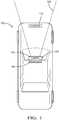
- FIG. 1schematically illustrates a vehicle 100 including a camera-based detector device 102.
- This exampleincludes a camera 104 and a processor 106.
- the camera 104has a field of view 108 within which the camera 104 is capable of providing information regarding the environment near or in a pathway of the vehicle 100.
- the processor 106is configured to use information output from the camera 104 to determine whether one or more objects is within the environment corresponding to the field of view 108. In other words, the processor 106 is configured to determine whether an object is within the camera's field of view 108.
- the processor 106includes at least one computing device, such as a microprocessor.
- the computing deviceis configured or otherwise programmed to make object detection determinations consistent with those described below.
- the processor 106in some examples includes on-board memory and in other examples the processor 106 is configured to communicate with a remotely located memory using known wireless communication techniques.
- the processor 106may be a dedicated device that is a portion of the camera-based detector device 102 or may be a portion of another processor or controller located on the vehicle 100.
- At least one other type of detector 110is provided on the vehicle 100.
- the detector 110comprises a LIDAR detector.
- the detector 110comprises a RADAR detector.
- the type of information or data provided by the detector 110is different than that provided by the camera 104.
- the detector 110has a field of view (not illustrated) that at least partially overlaps with the field of view 108 of the camera 104.
- references to the camera's field of view and the camera's output within this descriptionshould be considered synonymous or interchangeable unless the context requires a different interpretation.
- the processor 106when the processor 106 is described as selecting a portion of the camera output or selecting a portion of the camera's field of view, that should be understood to refer to the processor 106 utilizing information from the camera 104 corresponding to an image or other output from the camera 104 that indicates the contents of the environment within the camera's field of view 108.
- Figure 2is a flowchart diagram 120 that summarizes an example approach of detecting an object, which may include identifying an object's presence, type, location, movement or a combination of these.
- the technique summarized in Figure 2begins at 122 where the processor 106 obtains information regarding potential objects in the camera field of view 108 from the at least one other type of detector 110.
- the processor 106selects at least one area within the camera field of view containing a possible object based on the information obtained from the other type of sensor 110.
- the processor 106is configured to recognize clustered data from the detector 110 that corresponds to a potential object location within the camera field of view 108.
- the processor 106determines an Objectness of the selected area using information from the output of the camera 104. Known Objectness determining techniques are used in some example embodiments.
- LiDAR or Radar informationcan be used.
- LiDARprovides intensity detection in addition to point cloud.
- Objectnesscan be computed from LiDAR intensity such as averaging the LiDAR intensity in a patch.
- Radar Doppler informationcan be used to define motion Objectness.
- Objectness determination techniquesThere are a variety of known Objectness determination techniques that may be used for determining the Objectness of the selected portion. Those skilled in the art who have the benefit of this description will be able to select an appropriate Objectness determination technique to meet their particular needs. For example, a known fast Fourier transform technique, a Walsh Hadamard transform technique, a standard deviation filter technique, a local co-occurrence matrix technique or a global color spatial-distribution technique may be used. Further, the Objectness determination made by the processor 106 can be based on a combination of known Objectness measuring techniques.
- Figure 3schematically illustrates information obtained by the processor 106 regarding an output, such as an image, 130 from the camera 104.
- a plurality of data 132are based on an output from the detector 110.
- the data 132correspond to detection by the detector 110 that may indicate an object within the field of view of the detector 110 and the corresponding portion of the camera field of view.
- the entire camera output or image 130does not contain data corresponding to an output from the detector 110.
- the processor 106need not consider the entire camera output 130. Instead, portions or areas of the camera output 130 that do not contain information corresponding to an output from the detector 110 may be ignored by the processor 106 when determining an Objectness of the camera output.
- the processor 106is configured to select one or more portions of the camera output 130 that include information from the detector 110 regarding a potential object in such a portion of the camera output.
- the processor 106has information or programming that relates positions from the output of the detector 110 to positions or areas within the camera output 130.
- portions 134each include a sufficient number of data points or indications corresponding to information from the detector 110 that may indicate the presence of an object.
- the portions 134 in this exampleare considered clusters of such information or data points from the detector 110.
- the manner in which the clusters 134 are determined by the processor 106 or another processor associated with the detector 110may vary depending on the particular embodiment. An example cluster determination technique is described below, which is particularly useful with LIDAR-based detectors.
- the detection regionmay be created from selecting a region around the radar detection as it is sparse compared to LiDAR. The size of the region can be set based on the range of the detection.
- Figure 4schematically illustrates an example technique in which the processor 106 selects a portion 134 of the camera output 130 and determines an Objectness of that portion 134.
- the processor 106divides the portion 134 into a plurality of windows or segments and determines an Objectness of each of those segments.
- the processor 106in this example also determines a total Objectness for the entire portion 134.
- the Objectness determination or object detection output from the processor 106is based on a combination of the respective Objectness of the individual segments of the portion 134 and the total Objectness determination regarding the entire portion 134.
- the processor 106 in this examplearranges different segments within the portion 134 so that the different segments have different geometries.
- a first segment 140has a rectangular geometry that appears relatively tall and narrow in the illustration.
- the data points or information 132 within that segment 140have a spatial distribution such that a relatively long and narrow rectangular segment geometry fits well or corresponds to the arrangement or spatial orientation of that data or information from the detector 110.
- Other segments 142, 144 and 146are also rectangular but closer to a square shape because the data points or information 132 within each of those windows or segments fits better with a square shaped segment.
- the processor 106divides the portion 134 into equally sized and similarly configured segments for purposes of determining an Objectness of each of those segments.
- Objectness for each window or segmentis determined in some embodiments by dividing each of the segments 140-146 into multiple small windows or patches.
- the patchescomprise superpixels.
- An example configuration of patches 150 for the example segment 146is schematically shown in Figure 4 . Although rectangular patches 150 are illustrated in a 4 x 4 matrix arrangement that configuration is an example for discussion purposes and other tessellations can be used.
- the processor 106determines an Objectness score for each patch 150 based on the distinctiveness of the respective patches 150 with respect to the surrounding patches.
- the parameters for calculating the scoreare based on one or more known techniques in this embodiment such as saliency, Multiscale PCA (Principle Component Analysis), Fast Fourier Transform, Walsh Hadamard Transform, Local Co -Occurrence Matrix, HOG, edge density, etc.
- Objectnesscan be defined from a combination of the scores at both the patch and full segment or window level. For example, the Objectness of each patch 150 provides one measure or determination while the total Objectness of the entire segment 146 provides another measure.
- the processor 106determines the Objectness of each segment based on the total Objectness of the segment and the Objectness of each of the patches within that segment. Multiple Objectness determinations at the patch and segment or level can be combined as needed. Most of the previous work on Objectness has focused only on the total Objectness of a single image.
- the Objectness determinationis based on information from the output of the camera 104.
- the processor 106uses known image processing and Objectness determining techniques in this example.
- the Objectness determinationis not based on the data or information from the detector 110. Instead, the information from the detector 110 is used for locating the portions of the camera output that are more likely to contain an object than other portions of the camera output. Once those portions have been identified, the processor 106 is able to focus in on selected portions of the camera output for purposes of making an Objectness determination. Utilizing information from at least one other type of detector to direct or focus the Objectness determinations by the processor 106 reduces the computational load on the processor 106.
- the processor 106does not need to process or analyze the entire image or camera output 130.
- the disclosed example techniqueincreases processing speed and reduces processing complexity without sacrificing accuracy of object detection, location, identification, or tracking.
- the output from the detector 110does not need to be part of the Objectness determination based on the camera output but it may be used in combination with the Objectness determination to provide additional information regarding a detected object.
- the detector outputmay provide more detailed location or three-dimensional information regarding a detected object.
- the processor 106in some examples is configured to rank the Objectness of the various segments 140-146 within a selected portion 134.
- the segment or segments having a higher rankare selected by the processor 106 to identify or locate an object within the output or field of view of the camera 104.
- the processor 106utilizes a series of camera outputs that are related in a time sequence.
- the camera 104provides a sequence of images over time.
- the processor 106utilizes the disclosed example technique for selecting portions of each of those images based on information from the detector 110 and makes Objectness determinations regarding those portions. Over time the processor 106 is able to track the position or movement of an object detected within the output of the camera 104.
- the processor 106is configured to consider multiple frame Objectness and add motion cues to the Objectness measure.
- a clustering techniqueincludes segmenting a point-cloud from a LIDAR detector.
- ground-pointsthat belong to the ground surface constitute the majority of a typical point-cloud from a LIDAR, and their removal significantly reduces the number of points involved in the proceeding computations.
- the identification and extraction of ground-pointsis suitable for this application for two main reasons: (i) the ground-points are easily identifiable since they are associated with planes, which are primitive geometrical objects with a simple mathematical models; and (ii) it is acceptable to assume that points of the point-cloud with the lowest height values are most likely to belong to the ground surface.
- This prior knowledgeis used to dictate a set of points for the initiation of the algorithm and eliminate the random selection seen in typical plane-fit techniques such as the RANdom Sample Consensus (RANSAC), resulting in much faster convergence.
- RANSACRANdom Sample Consensus
- a single plane modelis insufficient for the representation of the real ground surface as the ground points do not form a perfect plane and the LIDAR measurements introduce significant noise for long distance measurements. It has been observed that in most instances the ground surface exhibits changes in slope which need to be detected.
- the proposed ground plane fitting techniqueextends its applicability to such instances of the ground surface by dividing the point-cloud into segments along the x-axis (direction of travel of the vehicle), and applying the ground plane fitting algorithm in each one of those segments.
- the ground plane fittingstarts by deterministically extracting a set of seed points with low height values which are then used to estimate the initial plane model of the ground surface.
- Each point in the point-cloud segment Pis evaluated against the estimated plane model and produces the distance from the point to its orthogonal projection on the candidate plane. This distance is compared to a user defined threshold Thdist, which decides whether the point belongs to the ground surface or not.
- Thdista user defined threshold
- the points belonging to the ground surfaceare used as seeds for the refined estimation of a new plane model and the process repeats for Niter number of times.
- the ground points resulting from this algorithm for each of the point-cloud segmentscan be concatenated and provide the entire ground plane.
- Algorithm 1Pseudocode of the ground plane fitting methodology for one segment of the point-cloud. Results: Pg are points belonging to ground surface; Png are points not belonging to ground surface.
- LPRlowest point representative
- the covariance matrix Ccaptures the dispersion of the seed points and its three singular vectors that can be computed by its singular value decomposition (SVD), describe the three main directions of this dispersion. Since the plane is a flat surface, the normal N, which is perpendicular to the plane, indicates the direction with the least variance and is captured by the singular vector corresponding to the smallest singular value. After the acquisition of N, d is directly computed from Eq. 1 by substituting X with S which is a good representative for the points belonging to the plane.
- Ssingular value decomposition
- the remaining points Png that do not belong to the ground surfaceneed to form or be organized into clusters to be used in higher level post processing schemes.
- the goalis for each point that is an element of Png (pk ⁇ Png) to acquire a label '1' that is indicative of a cluster identity while using simple mechanisms that will ensure the fast running time and low complexity of the process.
- the multi-layer structure of the 3D point-cloudstrongly resembles the row-wise structure of 2D images with the main differences being the non-uniform number of elements in each layer and the circular shape of each layer.
- the methodologytreats the 3D points as pixels of an image and adapts a two-run connected component labeling technique from binary images [ L. He, Y. Chao, and K. Suzuki, "A run-based two-scan labeling algorithm," IEEE Transactions on Image Processing, vol. 17, no. 5, pp. 749-756, 2008 ] to produce a real time 3D clustering algorithm.
- a layer of points that are produced from the same LIDAR ringis named a scan-line.
- elements of the scan-lineare organized in vectors of contiguous point runs.
- a runis defined as the number of consecutive non-ground points in a scan line that has the same label. That is, the elements within a run share the same label and are the main building blocks of the clusters.
- the point-cloud Pngis traversed in a raster counterclockwise fashion starting from the top scan-line.
- the runs of the first scan-lineare formed and each receives its own newLabel which is inherited or used for all of the point-elements in the scan-line.
- the runs of the first scan-linethen become the runsAbove and are used to propagate their labels to the runs in the subsequent scan-line.
- the labelis propagated to a new run when the distance between a point of the new run and its nearest neighbor in the prior scan-line above is less than Thmerge.
- the selected or winning labelis the smallest one.
- Algorithm 2Pseudocode of the scan line run clustering. Results: labels are labels of the non ground points.
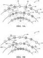
- Figure 5Bdemonstrates the assignment of a newLabel and the propagation of two labels.
- the nearest non-ground neighbor of 8is 2 and their distance is greater than Thmerge.
- labelsToMergeis empty and point 8 represents a new cluster.
- the nearest non-ground neighbor of 10is 3 with their distance smaller than Thmerge, which makes label 1 to propagate over to point 10.
- points 12 and 13are both close to their respective neighbors 5 and 6, and based on the non-empty labelsToMerge, label 2 is assigning to them.
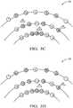
- the final scan-lineis considered in Figure 5C where one run is present. Points 17 and 19 have neighbors 10 and 12 which belong to different clusters and are both appropriate to propagate their label.
- the outline of the algorithmis straight forward, but for an efficient implementation of proposed solutions on (i) how to create runs, (ii) how to look for the nearest neighbor, and (iii) how to resolve label conflicts when merging two or more connected components.
- a smart indexing methodologyis utilized that overcomes the problem of the uneven number of elements in the different scan-lines and significantly reduces the number of queries for the nearest neighbor.
- each scanlinehas Ni number of points and that each point owns two indices; one global INDg which represents its position in the whole point-cloud, and one local INDl that identifies the point inside the scanline.
- the indexmight not indicate the nearest neighbor but a close enough point. In this case, it may be necessary to search through a number of its surrounding points for the nearest neighbor, but this number is far smaller than considering the whole scan-line.
- the proposed solutionis to find the nearest neighbors of the first and last points of a run via the smart indexing, form a kdtree structure with all the non-ground points within that range, and use this to search for nearest neighbors.
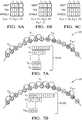
- FIGs 4A and 4BTwo visual examples of the smart indexing can be seen in Figures 4A and 4B .
- Figure 8Aalthough the number of points in the two scanlines is quite different, the randomly selected points with local indices 8, 16, 26, and 32 in the outer scan-line are indicated as the nearest neighbors of the points with local indices 5, 9, 15, and 18 respectively in the inner scan-line.
- Figure 8Bthe distribution of points is highly uneven but smart indexing still succeeds to indicate appropriate neighbors.
- These casesare common to the first few scanlines when some of their laser beams never return, because of absorption or very high distance. In rare cases where the number of points between consecutive scan-lines is vastly different or a significant portion of the scan-line is missing, the smart indexing will most likely fail. In these cases, the naive solution where the whole scan-line is considered as potential nearest neighbors still produces good results.
- Figure 9illustrates a non-limiting example of an object-detection system 10, hereafter referred to as the system 10, which is suitable for use on an automated vehicle, a host-vehicle 12 for example.
- the term 'automated vehicle'is not meant to suggest that fully automated or autonomous operation of the host-vehicle 12 is required. It is contemplated that the teachings presented herein are applicable to instances where the host-vehicle 12 is entirely manually operated by a human-operator (not shown) except for some small level of automation such as merely providing a warning to the operator of the presence of an object 14 and/or automatically operating the brakes of the host-vehicle 12 to prevent a collision with the object 14.
- the host-vehicle 12may be operable in an automated-mode 16 which may be a fully autonomous type of operation where the human-operator does little more than designate a destination, and/or the host-vehicle 12 may be operable in a manual-mode 18 where the human-operator generally controls the steering, accelerator, and brakes of the host-vehicle 12.
- the system 10includes a LIDAR 20 used to detect a point-cloud 22, see also Figures 5A-5D .
- the point-cloud 22may be indicative of the object 14 being proximate to the host-vehicle 12.
- the point-cloud 22is organized into a plurality of scan-lines 24. While Figures 5A-5D show only three instances of the scan-lines 24, this is only to simplify the drawings. That is, it is recognized that the point-cloud 22 from a typical commercially available example of the LIDAR 20 will provide a point-cloud with many more scan-lines, sixty-four scan-lines for example.
- the system 10includes a controller 26 in communication with the LIDAR 20.
- the controller 26may include a processor (not specifically shown) such as a microprocessor or other control circuitry such as analog and/or digital control circuitry including an application specific integrated circuit (ASIC) for processing data as should be evident to those in the art.
- the controller 26may include memory (not specifically shown), including non-volatile memory, such as electrically erasable programmable read-only memory (EEPROM) for storing one or more routines, thresholds, and captured data.
- the one or more routinesmay be executed by the processor to perform steps for determining the presence and location of the object 14 based on signals received by the controller 26 from the LIDAR 20 as described herein.
- the controller 26is configured to classify each detected point in the point-cloud as a ground-point 28 or a non-ground-point 30.
- Several methodshave been proposed to distinguish the ground-points 28 from the non-ground-points 30, as will be recognized by those in the art.
- the controller 26is further configured to define runs 32 of non-ground-points 30.
- Each run 32is characterized as a collection of one or multiple instances of adjacent non-ground-points in an instance of the scan-line 24 that is separated from a subsequent run 32 of one or more non-ground-points 30 by at least one instance of a ground-point 28. That is, each instance of a run 32 is defined by one or more instance of the non-ground-points 30 that are next to each other (i.e. adjacent to each other) without an intervening instance of a ground-point 28.
- the controller 26is further configured to define a cluster 34 of non-ground-points associated with the object 14. If multiple objects are present in the field-of-view of the LIDAR 20, there may be multiple instances of point-clouds 34 in the point-cloud 22.
- a cluster 34may be characterized by or include a first run 32A ( Figure 5B ) from a first scan-line 24A being associated with a second run 32B from a second scan-line 24B when a first point 22A from the first run 32A is displaced less than a distance-threshold 36 (see 'Thmerge' above) from a second point 22B from the second run 32B.
- an object-detection system(the system 10), a controller 26 for the system 10, and a method of operating the system 10 is provided.
- the process of organizing the non-ground-points 30 into runs 32, and then associating nearby runs 32 into clusters 34makes for an efficient way to process the point-cloud data from the LIDAR 20.
Landscapes
- Engineering & Computer Science (AREA)
- Physics & Mathematics (AREA)
- General Physics & Mathematics (AREA)
- Radar, Positioning & Navigation (AREA)
- Remote Sensing (AREA)
- Theoretical Computer Science (AREA)
- Computer Vision & Pattern Recognition (AREA)
- Computer Networks & Wireless Communication (AREA)
- Electromagnetism (AREA)
- Multimedia (AREA)
- Data Mining & Analysis (AREA)
- Quality & Reliability (AREA)
- Bioinformatics & Cheminformatics (AREA)
- Evolutionary Biology (AREA)
- Evolutionary Computation (AREA)
- General Engineering & Computer Science (AREA)
- Bioinformatics & Computational Biology (AREA)
- Artificial Intelligence (AREA)
- Life Sciences & Earth Sciences (AREA)
- Discrete Mathematics (AREA)
- Traffic Control Systems (AREA)
- Optical Radar Systems And Details Thereof (AREA)
Abstract
Description
- This disclosure generally relates to processing information available from a camera to locate, identify or track objects by using information from at least one other type of detector to improve aspects of the camera information analysis.
- Innovations in electronics and technology have made it possible to incorporate a variety of advanced features on automotive vehicles. Various sensing technologies have been developed for detecting objects or monitoring the surroundings in a vicinity or pathway of a vehicle. Such systems are useful for parking assist, lane departure detection and cruise control adjustment features, for example.
- More recently, automated vehicle features have become possible to allow for autonomous or semi-autonomous vehicle control. Sensors for such systems may incorporate cameras, ultrasonic sensors, LIDAR (light detection and ranging) detectors or radar detectors for determining when an object or another vehicle is in the pathway of or otherwise near the vehicle. Depending on the particular implementation, information from such a sensor may be used for automating at least a portion of the vehicle control or providing an indication to a driver regarding the conditions around the vehicle.
- While such information is useful, it is not obtained without challenges. For example, the information from a camera detector can require relatively large amounts of processing capacity and time to make useful determinations. The same is true of other types of sensors or detectors. One challenge those skilled in the art are trying to overcome is how to handle information from such sensors or detectors in an efficient manner within the capabilities of the types of processors that are economical to include on vehicles.
- An illustrative example object detection system includes a camera having a field of view. The camera provides an output comprising information regarding potential objects within the field of view. A processor is configured to select a portion of the camera output based on information from at least one other type of detector that indicates a potential object in the selected portion. The processor determines an Objectness of the selected portion based on information in the camera output regarding the selected portion.
- The processor may be configured to locate a plurality of segments in the selected portion, divide at least one of the segments into patches, and determine the Objectness of each of the patches, respectively. The processor may be configured to determine a total Objectness of an entire at least one of the segments, and the processor may be configured to determine the Objectness of the at least one of the segments based on the Objectness of each of the patches and the total Objectness. The processor may be configured to divide up the selected portion into segments, and the processor may be configured to arrange the segments based on an Objectness of the respective segments.
- The segments may include at least one segment having a first geometry and at least one other segment having a second, different geometry. At least the first geometry may correspond to a distribution of data points from the at least one other type of detector within the at least one segment.
- The processor may be configured to ignore other parts of the camera output that do not include information from the at least one other type of detector indicating a potential object in the other parts of the camera output.
- The object detection system may comprise the at least one other type of detector, wherein the at least one other type of detector may comprise one of a radar detector or a LIDAR detector.
- The processor may be configured to recognize a clustered set of data points from the at least one other type of detector, and the processor may be configured to select at least one clustered set of data points as the selected portion.
- The at least one other type of detector may provide a LIDAR output having an intensity; and the processor may determine the Objectness from at least one of the camera output and the intensity of the LIDAR output. The camera output may comprise a plurality of images, the plurality of images may be in a time-based sequence, the processor may be configured to use the plurality of images to determine motion cues corresponding to movement of a potential object in the selected portion, and the processor may be configured to use the motion cues when determining the Objectness of the selected portion.
- The processor may be configured to determine a respective Objectness of a plurality of segments of the selected portion, the processor may be configured to rank the Objectness of each of the segments, and the processor may be configured to select a highest ranked Objectness to identify a location of a potential object. The processor may be configured to provide an object location estimation within an identified area of the selected portion of the camera output.
- An illustrative example method of detecting at least one potential object includes selecting a portion of a camera output based on information from at least one other type of detector that indicates a potential object in the selected portion and determining an Objectness of the selected portion based on information in the camera output regarding the selected portion.
- The method may include dividing up the selected portion into segments and determining the Objectness of each of the segments, respectively. The method may include dividing at least one of the segments into a plurality of patches, determining a total Objectness of the entire at least one of the segments, determining an Objectness of each of the patches, and determining the Objectness of the at least one of the segments based on the Objectness of each of the patches and the total Objectness.
- Dividing up the selected portion into segments may comprise configuring respective geometries of the segments based on information from the at least one other type of detector, wherein the segments may include at least one segment having a first geometry and at least one other segment having a second, different geometry, and at least the first geometry may correspond to a distribution of data points from the at least one other type of detector within the at least one segment.
- The method may include ignoring other parts of the camera output that do not include information from the at least one other type of detector indicating a potential object in the other parts of the camera output.
- Selecting the portion of the camera output may comprise recognizing a clustered set of data points from the at least one other type of detector.
- The camera output may comprise a plurality of images in a time-based sequence and the method may comprise using the plurality of images to determine movement cues of a potential object in the selected portion, and using the movement cues to determine the Objectness of the selected portion.
- The method may include determining a respective Objectness of a plurality of segments of the selected portion, ranking the Objectness of each of the segments, and selecting a highest ranked Objectness to identify a location of a potential object.
- The method may include providing an object location estimation within an identified area of the selected portion of the camera output.
- The at least one other type of detector may provides a LIDAR output having an intensity, and determining the Objectness may comprise using at least one of the camera (104) output and the intensity of the LIDAR output.
- Further features and advantages will appear more clearly on a reading of the following detailed description of at least one disclosed embodiment, which is given by way of non-limiting example only and with reference to the accompanying drawings.
Figure 1 schematically illustrates a vehicle including a camera-based detector device designed according to an embodiment of this invention.Figure 2 is a flowchart diagram summarizing an example technique designed according to an embodiment of this invention.Figure 3 schematically illustrates a feature of processing information within a camera field of view.Figure 4 schematically illustrates a feature of processing information from a selected portion of the camera field of view.Figures 5A, 5B ,5C, and 5D schematically illustrate four stages that exemplify the processes of an example Scan Run Line (SLR) clustering algorithm where circles represent points and triangles report the cluster labels in accordance with one embodiment.Figures 6A, 6B, and 6C cooperatively schematically illustrate an example label conflict resolving technique based onFigures 5A-5D in accordance with one embodiment.Figures 7A and 7B are an example of bridging two ends of a circular scan-line in accordance with one embodiment.Figure 8A schematically illustrates an example smart indexing when two scan-lines have a significant difference in the number of points andFigure 8B when points in both lines are missing because of noise and physical limitations of the sensor in accordance with one embodiment; andFigure 9 is a diagram of an object detection system in accordance with one embodiment.- Embodiments of this invention provide an ability to process information from a camera-based detector in an efficient manner. Information from at least one other type of detector is used for selecting a portion of a camera output and object detection is based on determining an Objectness of that selected portion.
Figure 1 schematically illustrates avehicle 100 including a camera-baseddetector device 102. This example includes acamera 104 and aprocessor 106. Thecamera 104 has a field ofview 108 within which thecamera 104 is capable of providing information regarding the environment near or in a pathway of thevehicle 100. Theprocessor 106 is configured to use information output from thecamera 104 to determine whether one or more objects is within the environment corresponding to the field ofview 108. In other words, theprocessor 106 is configured to determine whether an object is within the camera's field ofview 108.- In an example embodiment, the
processor 106 includes at least one computing device, such as a microprocessor. The computing device is configured or otherwise programmed to make object detection determinations consistent with those described below. Theprocessor 106 in some examples includes on-board memory and in other examples theprocessor 106 is configured to communicate with a remotely located memory using known wireless communication techniques. Theprocessor 106 may be a dedicated device that is a portion of the camera-baseddetector device 102 or may be a portion of another processor or controller located on thevehicle 100. - At least one other type of
detector 110 is provided on thevehicle 100. In some embodiments, thedetector 110 comprises a LIDAR detector. In other embodiments, thedetector 110 comprises a RADAR detector. The type of information or data provided by thedetector 110 is different than that provided by thecamera 104. Thedetector 110 has a field of view (not illustrated) that at least partially overlaps with the field ofview 108 of thecamera 104. - Reference to the camera's field of view and the camera's output within this description should be considered synonymous or interchangeable unless the context requires a different interpretation. For example, when the
processor 106 is described as selecting a portion of the camera output or selecting a portion of the camera's field of view, that should be understood to refer to theprocessor 106 utilizing information from thecamera 104 corresponding to an image or other output from thecamera 104 that indicates the contents of the environment within the camera's field ofview 108. Figure 2 is a flowchart diagram 120 that summarizes an example approach of detecting an object, which may include identifying an object's presence, type, location, movement or a combination of these. The technique summarized inFigure 2 begins at 122 where theprocessor 106 obtains information regarding potential objects in the camera field ofview 108 from the at least one other type ofdetector 110. At 124, theprocessor 106 selects at least one area within the camera field of view containing a possible object based on the information obtained from the other type ofsensor 110. In an example embodiment, theprocessor 106 is configured to recognize clustered data from thedetector 110 that corresponds to a potential object location within the camera field ofview 108. At 126, theprocessor 106 determines an Objectness of the selected area using information from the output of thecamera 104. Known Objectness determining techniques are used in some example embodiments.- In most cases camera information is used to compute Objectness. In another embodiment, LiDAR or Radar information can be used. For example, LiDAR provides intensity detection in addition to point cloud. Objectness can be computed from LiDAR intensity such as averaging the LiDAR intensity in a patch. In another example, Radar Doppler information can be used to define motion Objectness.
- There are a variety of known Objectness determination techniques that may be used for determining the Objectness of the selected portion. Those skilled in the art who have the benefit of this description will be able to select an appropriate Objectness determination technique to meet their particular needs. For example, a known fast Fourier transform technique, a Walsh Hadamard transform technique, a standard deviation filter technique, a local co-occurrence matrix technique or a global color spatial-distribution technique may be used. Further, the Objectness determination made by the
processor 106 can be based on a combination of known Objectness measuring techniques. Figure 3 schematically illustrates information obtained by theprocessor 106 regarding an output, such as an image, 130 from thecamera 104. A plurality ofdata 132, such as detection points, are based on an output from thedetector 110. Thedata 132 correspond to detection by thedetector 110 that may indicate an object within the field of view of thedetector 110 and the corresponding portion of the camera field of view.- As can be appreciated from the illustration, the entire camera output or
image 130 does not contain data corresponding to an output from thedetector 110. One feature of this example embodiment is that theprocessor 106 need not consider theentire camera output 130. Instead, portions or areas of thecamera output 130 that do not contain information corresponding to an output from thedetector 110 may be ignored by theprocessor 106 when determining an Objectness of the camera output. - Instead, the
processor 106 is configured to select one or more portions of thecamera output 130 that include information from thedetector 110 regarding a potential object in such a portion of the camera output. Theprocessor 106 has information or programming that relates positions from the output of thedetector 110 to positions or areas within thecamera output 130. InFigure 3 ,portions 134 each include a sufficient number of data points or indications corresponding to information from thedetector 110 that may indicate the presence of an object. Theportions 134 in this example are considered clusters of such information or data points from thedetector 110. The manner in which theclusters 134 are determined by theprocessor 106 or another processor associated with thedetector 110 may vary depending on the particular embodiment. An example cluster determination technique is described below, which is particularly useful with LIDAR-based detectors. On the other hand, for an embodiment using Radar the detection region may be created from selecting a region around the radar detection as it is sparse compared to LiDAR. The size of the region can be set based on the range of the detection. Figure 4 schematically illustrates an example technique in which theprocessor 106 selects aportion 134 of thecamera output 130 and determines an Objectness of thatportion 134. Theprocessor 106 divides theportion 134 into a plurality of windows or segments and determines an Objectness of each of those segments. Theprocessor 106 in this example also determines a total Objectness for theentire portion 134. In some examples, the Objectness determination or object detection output from theprocessor 106 is based on a combination of the respective Objectness of the individual segments of theportion 134 and the total Objectness determination regarding theentire portion 134.- The
processor 106 in this example arranges different segments within theportion 134 so that the different segments have different geometries. For example, afirst segment 140 has a rectangular geometry that appears relatively tall and narrow in the illustration. The data points orinformation 132 within thatsegment 140 have a spatial distribution such that a relatively long and narrow rectangular segment geometry fits well or corresponds to the arrangement or spatial orientation of that data or information from thedetector 110.Other segments information 132 within each of those windows or segments fits better with a square shaped segment. - In some examples, the
processor 106 divides theportion 134 into equally sized and similarly configured segments for purposes of determining an Objectness of each of those segments. - Objectness for each window or segment is determined in some embodiments by dividing each of the segments 140-146 into multiple small windows or patches. In some embodiments the patches comprise superpixels. An example configuration of
patches 150 for theexample segment 146 is schematically shown inFigure 4 . Althoughrectangular patches 150 are illustrated in a 4 x 4 matrix arrangement that configuration is an example for discussion purposes and other tessellations can be used. - When at least one of the segments is divided into
patches 150, theprocessor 106 determines an Objectness score for eachpatch 150 based on the distinctiveness of therespective patches 150 with respect to the surrounding patches. The parameters for calculating the score are based on one or more known techniques in this embodiment such as saliency, Multiscale PCA (Principle Component Analysis), Fast Fourier Transform, Walsh Hadamard Transform, Local Co -Occurrence Matrix, HOG, edge density, etc. Objectness can be defined from a combination of the scores at both the patch and full segment or window level. For example, the Objectness of eachpatch 150 provides one measure or determination while the total Objectness of theentire segment 146 provides another measure. Theprocessor 106 in some embodiments determines the Objectness of each segment based on the total Objectness of the segment and the Objectness of each of the patches within that segment. Multiple Objectness determinations at the patch and segment or level can be combined as needed. Most of the previous work on Objectness has focused only on the total Objectness of a single image. - The Objectness determination is based on information from the output of the
camera 104. Theprocessor 106 uses known image processing and Objectness determining techniques in this example. The Objectness determination is not based on the data or information from thedetector 110. Instead, the information from thedetector 110 is used for locating the portions of the camera output that are more likely to contain an object than other portions of the camera output. Once those portions have been identified, theprocessor 106 is able to focus in on selected portions of the camera output for purposes of making an Objectness determination. Utilizing information from at least one other type of detector to direct or focus the Objectness determinations by theprocessor 106 reduces the computational load on theprocessor 106. Theprocessor 106 does not need to process or analyze the entire image orcamera output 130. The disclosed example technique increases processing speed and reduces processing complexity without sacrificing accuracy of object detection, location, identification, or tracking. - The output from the
detector 110 does not need to be part of the Objectness determination based on the camera output but it may be used in combination with the Objectness determination to provide additional information regarding a detected object. For example, the detector output may provide more detailed location or three-dimensional information regarding a detected object. - The
processor 106 in some examples is configured to rank the Objectness of the various segments 140-146 within a selectedportion 134. The segment or segments having a higher rank are selected by theprocessor 106 to identify or locate an object within the output or field of view of thecamera 104. - In some examples, the
processor 106 utilizes a series of camera outputs that are related in a time sequence. For example, thecamera 104 provides a sequence of images over time. Theprocessor 106 utilizes the disclosed example technique for selecting portions of each of those images based on information from thedetector 110 and makes Objectness determinations regarding those portions. Over time theprocessor 106 is able to track the position or movement of an object detected within the output of thecamera 104. - In some embodiments, the
processor 106 is configured to consider multiple frame Objectness and add motion cues to the Objectness measure. For this case, a motion cue is computed from a sequence of images and the Objectness measure is defined as Objectness = motion Objectness + segment Objectness + patch Objectness. Although summation is used in this example, other groupings can be used to combine the different measures. - As mentioned above, different techniques may be used in different embodiments for processing information from the
detector 110 to allow theprocessor 106 to select appropriate portions of the camera output within which to perform an Objectness determination for detecting an object. For embodiments that include a LIDAR detector as thedetector 110, a clustering technique is useful. One example clustering technique includes segmenting a point-cloud from a LIDAR detector. - The following paragraphs describe an example methodology for the segmentation of a point-cloud received by a 360° coverage LIDAR sensor. First, a deterministic iterative multiple plane fitting technique named Ground Plane Fitting (GPF) is presented for the fast extraction of the ground points. Next is a point-cloud clustering methodology named Scan Line Run (SLR) which is directed to algorithms for connected components labeling in binary images from a LIDAR. Each paragraph is conceptually divided in three sections including a brief reasoning behind the algorithm selection along with the definition of new terms, the overview of the algorithm according to the pseudo-code diagrams, and discussion of algorithm implementation details.
- Cloud points that belong to the ground surface constitute the majority of a typical point-cloud from a LIDAR, and their removal significantly reduces the number of points involved in the proceeding computations. The identification and extraction of ground-points is suitable for this application for two main reasons: (i) the ground-points are easily identifiable since they are associated with planes, which are primitive geometrical objects with a simple mathematical models; and (ii) it is acceptable to assume that points of the point-cloud with the lowest height values are most likely to belong to the ground surface. This prior knowledge is used to dictate a set of points for the initiation of the algorithm and eliminate the random selection seen in typical plane-fit techniques such as the RANdom Sample Consensus (RANSAC), resulting in much faster convergence.
- Generally, a single plane model is insufficient for the representation of the real ground surface as the ground points do not form a perfect plane and the LIDAR measurements introduce significant noise for long distance measurements. It has been observed that in most instances the ground surface exhibits changes in slope which need to be detected. The proposed ground plane fitting technique extends its applicability to such instances of the ground surface by dividing the point-cloud into segments along the x-axis (direction of travel of the vehicle), and applying the ground plane fitting algorithm in each one of those segments.
- As depicted in the main loop of
Algorithm 1, for each of the point-cloud segments the ground plane fitting starts by deterministically extracting a set of seed points with low height values which are then used to estimate the initial plane model of the ground surface. Each point in the point-cloud segment P is evaluated against the estimated plane model and produces the distance from the point to its orthogonal projection on the candidate plane. This distance is compared to a user defined threshold Thdist, which decides whether the point belongs to the ground surface or not. The points belonging to the ground surface are used as seeds for the refined estimation of a new plane model and the process repeats for Niter number of times. Finally, the ground points resulting from this algorithm for each of the point-cloud segments can be concatenated and provide the entire ground plane. - Algorithm 1: Pseudocode of the ground plane fitting methodology for one segment of the point-cloud. Results: Pg are points belonging to ground surface; Png are points not belonging to ground surface.
1 Initialization: 2 P : input point-cloud 3 Niter : number ofiterations 4 NLPR : number of points used to estimate the lowest point representative (LPR) 5 Thseeds : threshold for points to be consideredinitial seeds 6 Thdist : threshold distance from theplane 7 Main Loop: 8 Pg = ExtractInitialSeeds( P; NLPR; Thseeds ); 9 for i = 1 : Niter do 10 model = EstimatePlane( Pg ); 11 clear( Pg; Png ); 12 for k = 1 : |P| do 13 if model( pk ) < Thdist then 14 Pg ← pk; 15 else 16 Png ← pk; 17end 18end 19end 20 ExtractInitialSeeds: 21 Psorted = SortOnHeight( P ); 22 LPR = Average( Psorted( 1 : NLPR ) ); 23 fork= 1 : |P| do 24 if pk:height < LPR:height + Thseeds then 25 seeds ←pk 26end 27end 28 return( seeds );


1 Initialization: 2 P : input point-cloud 3 Nscanlines : number ofscan lines 4 Thrun : threshold for points to belong in thesame run 5 Thmerge : threshold to merge neighboringruns 6 newLabel = 1 :label identity 7 Main Loop: 8 runsAbove = FindRuns( scanline1 ); 9 for i = 1 : |runsAbove| do 10 runsAbovei:label = newLabel; 11 newLabel + +; 12end 13 for i = 2 : Nscanlines do 14 runsCurrent = FindRuns( scanlinei ); 15 UpdateLabels( runsCurrent; runsAbove ); 16 runsAbove = runsCurrent; 17end 18 ExtractClusters(); 19 UpdateLabels: 20 for i = 1 : |runsCurrent| do 21 for j = 1 : |PrunsCurrenti| do 22 pNN = FindNearestNeighbor( pj ; runsAbove ); 23 labelsToMerge pNN:label; 24end 25 if isEmpty( labelsToMerge ) then 26 runsCurrenti:label = newLabel; 27 newLabel + +; 28 else 29 1R = min( labelsToMerge ); 30 runsCurrenti:label = 1R; 31 MergeLabels( labelsToMerge ); 32end 33 end
- i) A run is created upon the first visit of the scan-line as a vector of indices and holds information on which consecutive points are close enough to be considered a single block inside a scan-line. Considering the circular form of the scan-lines, a run may bridge over the first and last indices. When detected, this case is resolved by attaching the indices of the ending of the scan-line at the beginning of the indices of the first run as seen in the example of
Figures 7A and 7B . - ii) When the input point-cloud is expressed in polar or cylindrical coordinates with points x = [r θ z], then indexing the nearest neighbor in the scan-line above can be viewed as simply comparing θ values. In autonomous vehicle applications though, clustering is one small component of a much larger system of sensors and algorithms, and the Cartesian coordinate system is preferred for compatibility reasons. Implementation-wise, the naive solution is to build a kdtree structure with all the non-ground points in the scan-line above and use this to find each nearest neighbor, resulting in a suboptimal but viable solution that can be further refined.


- iii) The methodology to resolve label merging conflicts is being introduced in [L. He, Y. Chao, and K. Suzuki, "A run-based two-scan labeling algorithm," IEEE Transactions on Image Processing, vol. 17, no. 5, pp. 749-756, 2008] where all the details for the implementation and deep understanding are provided. Following, a brief presentation of the essentials along with a simple example is given.
Claims (15)
- An object detection system, comprising:a camera (104) having a field of view (108), the camera (104) providing an output comprising information regarding potential objects within the field of view; anda processor (106) that is configured to select a portion (134) of the camera (104) output based on information from at least one other type of detector (110) that indicates a potential object in the selected portion (134), the processor (106) determining an Objectness of the selected portion (134) based on information in the camera (104) output regarding the selected portion (134).
- The object detection system of claim 1, wherein the processor (106) is configured to
locate a plurality of segments (140-146) in the selected portion (134);
divide at least one of the segments (140-146) into patches (150); and
determine the Objectness of each of the patches (150), respectively. - The object detection system according to any one of the preceding claims, wherein
the processor (106) is configured to divide up the selected portion (134) into segments (140-146); and
the processor (106) is configured to arrange the segments (140-146) based on an Objectness of the respective segments (140-146). - The object detection system according to any one of the preceding claims, wherein the processor (106) is configured to ignore other parts of the camera (104) output that do not include information from the at least one other type of detector (110) indicating a potential object in the other parts of the camera (104) output.
- The object detection system according to any one of the preceding claims, comprising the at least one other type of detector (110) and wherein the at least one other type of detector (110) comprises one of a radar detector or a LIDAR detector.
- The object detection system according to any one of the preceding claims, wherein
the processor (106) is configured to recognize a clustered set of data points from the at least one other type of detector (110); and
the processor (106) is configured to select at least one clustered set of data points as the selected portion (134). - The object detection system according to any one of the preceding claims, wherein
the at least one other type of detector (110) provides a LIDAR output having an intensity; and
the processor (106) determines the Objectness from at least one of the camera (104) output and the intensity of the LIDAR output. - The object detection system according to any one of the preceding claims, wherein
the camera (104) output comprises a plurality of images;
the plurality of images are in a time-based sequence;
the processor (106) is configured to use the plurality of images to determine motion cues corresponding to movement of a potential object in the selected portion (134); and
the processor (106) is configured to use the motion cues when determining the Objectness of the selected portion (134). - The object detection system according to any one of the preceding claims, wherein
the processor (106) is configured to determine a respective Objectness of a plurality of segments (140-146) of the selected portion (134);
the processor (106) is configured to rank the Objectness of each of the segments (140-146); and
the processor (106) is configured to select a highest ranked Objectness to identify a location of a potential object. - A method of detecting at least one potential object, the method comprising:selecting a portion (134) of a camera (104) output based on information from at least one other type of detector (110) that indicates a potential object in the selected portion (134); anddetermining an Objectness of the selected portion (134) based on information in the camera (104) output regarding the selected portion (134).
- The method of claim 10, comprising
dividing up the selected portion (134) into segments (140-146); and
determining the Objectness of each of the segments (140-146), respectively. - The method according to any one of the claims 10 or 11, wherein
dividing up the selected portion (134) into segments (140-146) comprises configuring respective geometries of the segments (140-146) based on information from the at least one other type of detector (110);
the segments (140-146) include at least one segment having a first geometry and at least one other segment having a second, different geometry; and
at least the first geometry corresponds to a distribution of data points from the at least one other type of detector (110) within the at least one segment. - The method according to any one of the claims 10 to 12, comprising ignoring other parts of the camera (104) output that do not include information from the at least one other type of detector (110) indicating a potential object in the other parts of the camera (104) output.
- The method according to any one of the claims 10 to 13, wherein selecting the portion (134) of the camera (104) output comprises recognizing a clustered set of data points from the at least one other type of detector (110).
- The method according to any one of the claims 10 to 14, wherein
the at least one other type of detector (110) provides a LIDAR output having an intensity; and
determining the Objectness comprises using at least one of the camera (104) output and the intensity of the LIDAR output.
Applications Claiming Priority (2)
| Application Number | Priority Date | Filing Date | Title |
|---|---|---|---|
| US201662393311P | 2016-09-12 | 2016-09-12 | |
| US15/680,854US10366310B2 (en) | 2016-09-12 | 2017-08-18 | Enhanced camera object detection for automated vehicles |
Publications (2)
| Publication Number | Publication Date |
|---|---|
| EP3293669A1true EP3293669A1 (en) | 2018-03-14 |
| EP3293669B1 EP3293669B1 (en) | 2024-10-02 |
Family
ID=59686803
Family Applications (1)
| Application Number | Title | Priority Date | Filing Date |
|---|---|---|---|
| EP17187298.9AActiveEP3293669B1 (en) | 2016-09-12 | 2017-08-22 | Enhanced camera object detection for automated vehicles |
Country Status (3)
| Country | Link |
|---|---|
| US (1) | US10366310B2 (en) |
| EP (1) | EP3293669B1 (en) |
| CN (1) | CN107818557B (en) |
Cited By (3)
| Publication number | Priority date | Publication date | Assignee | Title |
|---|---|---|---|---|
| CN111352128A (en)* | 2018-12-21 | 2020-06-30 | 上海微功智能科技有限公司 | Multi-sensor fusion sensing method and system based on fusion point cloud |
| DE102020123920B3 (en) | 2020-09-15 | 2021-08-19 | Dr. Ing. H.C. F. Porsche Aktiengesellschaft | Method and system for the automatic labeling of radar data |
| DE102018131495B4 (en) | 2018-12-10 | 2023-08-10 | Valeo Schalter Und Sensoren Gmbh | Method for providing a 3-dimensional data field of a distance sensor from the perspective of an optical sensor and driving support system for carrying out the method |
Families Citing this family (22)
| Publication number | Priority date | Publication date | Assignee | Title |
|---|---|---|---|---|
| US20190005667A1 (en)* | 2017-07-24 | 2019-01-03 | Muhammad Zain Khawaja | Ground Surface Estimation |
| EP3483629B1 (en)* | 2017-11-09 | 2021-12-29 | Veoneer Sweden AB | Detecting a parking row with a vehicle radar system |
| US10762394B2 (en) | 2018-07-31 | 2020-09-01 | Intel Corporation | System and method for 3D blob classification and transmission |
| US11212506B2 (en) | 2018-07-31 | 2021-12-28 | Intel Corporation | Reduced rendering of six-degree of freedom video |
| US10893299B2 (en) | 2018-07-31 | 2021-01-12 | Intel Corporation | Surface normal vector processing mechanism |
| US11178373B2 (en) | 2018-07-31 | 2021-11-16 | Intel Corporation | Adaptive resolution of point cloud and viewpoint prediction for video streaming in computing environments |
| US10685476B2 (en)* | 2018-07-31 | 2020-06-16 | Intel Corporation | Voxels sparse representation |
| US10887574B2 (en) | 2018-07-31 | 2021-01-05 | Intel Corporation | Selective packing of patches for immersive video |
| US11204605B1 (en)* | 2018-08-03 | 2021-12-21 | GM Global Technology Operations LLC | Autonomous vehicle controlled based upon a LIDAR data segmentation system |
| US10884131B1 (en) | 2018-08-03 | 2021-01-05 | GM Global Technology Operations LLC | Conflict resolver for a lidar data segmentation system of an autonomous vehicle |
| DE102019127349A1 (en) | 2018-10-10 | 2020-04-16 | Intel Corporation | POINT CLOUD CODE STANDARD CONFORMITY DEFINITION IN COMPUTER ENVIRONMENTS |
| US11057631B2 (en) | 2018-10-10 | 2021-07-06 | Intel Corporation | Point cloud coding standard conformance definition in computing environments |
| KR102831462B1 (en)* | 2019-02-21 | 2025-07-09 | 현대모비스 주식회사 | Apparatus for detecting object of vehicle and method thereof |
| JP7312608B2 (en)* | 2019-05-23 | 2023-07-21 | 豊田合成株式会社 | Decorative parts for vehicles |
| US11460581B2 (en)* | 2019-06-10 | 2022-10-04 | Toyota Research Institute, Inc. | Systems and methods for reducing LiDAR points |
| GB202311795D0 (en)* | 2019-12-19 | 2023-09-13 | Motional Ad Llc | Foreground extraction using surface fitting |
| US11957974B2 (en) | 2020-02-10 | 2024-04-16 | Intel Corporation | System architecture for cloud gaming |
| WO2021189420A1 (en)* | 2020-03-27 | 2021-09-30 | 华为技术有限公司 | Data processing method and device |
| JP7420086B2 (en)* | 2021-01-13 | 2024-01-23 | 豊田合成株式会社 | Exterior parts for vehicles |
| CN113189583B (en)* | 2021-04-26 | 2022-07-01 | 天津大学 | Time-space synchronization millimeter wave radar and visual information fusion method |
| US11792644B2 (en) | 2021-06-21 | 2023-10-17 | Motional Ad Llc | Session key generation for autonomous vehicle operation |
| JP7518804B2 (en) | 2021-09-13 | 2024-07-18 | 株式会社デンソー | Object Recognition Device |
Citations (2)
| Publication number | Priority date | Publication date | Assignee | Title |
|---|---|---|---|---|
| US20100104199A1 (en)* | 2008-04-24 | 2010-04-29 | Gm Global Technology Operations, Inc. | Method for detecting a clear path of travel for a vehicle enhanced by object detection |
| US8989944B1 (en)* | 2013-11-26 | 2015-03-24 | Google Inc. | Methods and devices for determining movements of an object in an environment |
Family Cites Families (16)
| Publication number | Priority date | Publication date | Assignee | Title |
|---|---|---|---|---|
| US6859144B2 (en)* | 2003-02-05 | 2005-02-22 | Delphi Technologies, Inc. | Vehicle situation alert system with eye gaze controlled alert signal generation |
| JP2006264416A (en)* | 2005-03-22 | 2006-10-05 | Takata Corp | Object detection system, protection system, and vehicle |
| US7676087B2 (en)* | 2006-09-20 | 2010-03-09 | Delphi Technologies, Inc. | Method for identifying vehicles in electronic images |
| US8355539B2 (en)* | 2007-09-07 | 2013-01-15 | Sri International | Radar guided vision system for vehicle validation and vehicle motion characterization |
| US8452053B2 (en)* | 2008-04-24 | 2013-05-28 | GM Global Technology Operations LLC | Pixel-based texture-rich clear path detection |
| US8670592B2 (en)* | 2008-04-24 | 2014-03-11 | GM Global Technology Operations LLC | Clear path detection using segmentation-based method |
| US8332134B2 (en)* | 2008-04-24 | 2012-12-11 | GM Global Technology Operations LLC | Three-dimensional LIDAR-based clear path detection |
| US8917904B2 (en)* | 2008-04-24 | 2014-12-23 | GM Global Technology Operations LLC | Vehicle clear path detection |
| JP4377439B1 (en)* | 2008-06-12 | 2009-12-02 | 本田技研工業株式会社 | Vehicle periphery monitoring device |
| US20120288140A1 (en)* | 2011-05-13 | 2012-11-15 | Carnegie Mellon University | Method and system for selecting a video analysis method based on available video representation features |
| US9383753B1 (en)* | 2012-09-26 | 2016-07-05 | Google Inc. | Wide-view LIDAR with areas of special attention |
| US9285893B2 (en)* | 2012-11-08 | 2016-03-15 | Leap Motion, Inc. | Object detection and tracking with variable-field illumination devices |
| US10347127B2 (en)* | 2013-02-21 | 2019-07-09 | Waymo Llc | Driving mode adjustment |
| US9627330B2 (en)* | 2015-07-13 | 2017-04-18 | International Business Machines Corporation | Support for long channel length nanowire transistors |
| US9915951B2 (en)* | 2015-12-27 | 2018-03-13 | Toyota Motor Engineering & Manufacturing North America, Inc. | Detection of overhanging objects |
| US20170307743A1 (en)* | 2016-04-22 | 2017-10-26 | Delphi Technologies, Inc. | Prioritized Sensor Data Processing Using Map Information For Automated Vehicles |
- 2017
- 2017-08-18USUS15/680,854patent/US10366310B2/enactiveActive
- 2017-08-22EPEP17187298.9Apatent/EP3293669B1/enactiveActive
- 2017-09-12CNCN201710817563.3Apatent/CN107818557B/enactiveActive
Patent Citations (2)
| Publication number | Priority date | Publication date | Assignee | Title |
|---|---|---|---|---|
| US20100104199A1 (en)* | 2008-04-24 | 2010-04-29 | Gm Global Technology Operations, Inc. | Method for detecting a clear path of travel for a vehicle enhanced by object detection |
| US8989944B1 (en)* | 2013-11-26 | 2015-03-24 | Google Inc. | Methods and devices for determining movements of an object in an environment |
Non-Patent Citations (5)
| Title |
|---|
| DOMINIC ZENG WANG ET AL: "What could move? Finding cars, pedestrians and bicyclists in 3D laser data", ROBOTICS AND AUTOMATION (ICRA), 2012 IEEE INTERNATIONAL CONFERENCE ON, IEEE, 14 May 2012 (2012-05-14), pages 4038 - 4044, XP032450465, ISBN: 978-1-4673-1403-9, DOI: 10.1109/ICRA.2012.6224734* |
| DOUILLARD B ET AL: "On the segmentation of 3D LIDAR point clouds", ROBOTICS AND AUTOMATION (ICRA), 2011 IEEE INTERNATIONAL CONFERENCE ON, IEEE, 9 May 2011 (2011-05-09), pages 2798 - 2805, XP032033687, ISBN: 978-1-61284-386-5, DOI: 10.1109/ICRA.2011.5979818* |
| HIMMELSBACH M ET AL: "Fast segmentation of 3D point clouds for ground vehicles", INTELLIGENT VEHICLES SYMPOSIUM (IV), 2010 IEEE, IEEE, PISCATAWAY, NJ, USA, 21 June 2010 (2010-06-21), pages 560 - 565, XP031732220, ISBN: 978-1-4244-7866-8* |
| L. HE; Y. CHAO; K. SUZUKI: "A run-based two-scan labeling algorithm", IEEE TRANSACTIONS ON IMAGE PROCESSING, vol. 17, no. 5, 2008, pages 749 - 756, XP011206197 |
| ZERMAS DIMITRIS ET AL: "Fast segmentation of 3D point clouds: A paradigm on LiDAR data for autonomous vehicle applications", 2017 IEEE INTERNATIONAL CONFERENCE ON ROBOTICS AND AUTOMATION (ICRA), IEEE, 29 May 2017 (2017-05-29), pages 5067 - 5073, XP033127333, DOI: 10.1109/ICRA.2017.7989591* |
Cited By (5)
| Publication number | Priority date | Publication date | Assignee | Title |
|---|---|---|---|---|
| DE102018131495B4 (en) | 2018-12-10 | 2023-08-10 | Valeo Schalter Und Sensoren Gmbh | Method for providing a 3-dimensional data field of a distance sensor from the perspective of an optical sensor and driving support system for carrying out the method |
| CN111352128A (en)* | 2018-12-21 | 2020-06-30 | 上海微功智能科技有限公司 | Multi-sensor fusion sensing method and system based on fusion point cloud |
| CN111352128B (en)* | 2018-12-21 | 2023-03-24 | 上海微功智能科技有限公司 | Multi-sensor fusion sensing method and system based on fusion point cloud |
| DE102020123920B3 (en) | 2020-09-15 | 2021-08-19 | Dr. Ing. H.C. F. Porsche Aktiengesellschaft | Method and system for the automatic labeling of radar data |
| US12265902B2 (en) | 2020-09-15 | 2025-04-01 | Dr. Ing. H. C. F. Porsche Ag | Method and system for automatically labeling radar data |
Also Published As
| Publication number | Publication date |
|---|---|
| EP3293669B1 (en) | 2024-10-02 |
| CN107818557B (en) | 2022-02-22 |
| US10366310B2 (en) | 2019-07-30 |
| US20180075320A1 (en) | 2018-03-15 |
| CN107818557A (en) | 2018-03-20 |
Similar Documents
| Publication | Publication Date | Title |
|---|---|---|
| EP3293669B1 (en) | Enhanced camera object detection for automated vehicles | |
| EP3293670B1 (en) | Lidar object detection system for automated vehicles | |
| US11720799B2 (en) | Object detection neural networks | |
| Simon et al. | Complexer-yolo: Real-time 3d object detection and tracking on semantic point clouds | |
| US11003921B2 (en) | Apparatus and method for distinguishing false target in vehicle and vehicle including the same | |
| Asvadi et al. | 3D object tracking using RGB and LIDAR data | |
| Suhr et al. | Automatic parking space detection and tracking for underground and indoor environments | |
| Xiao et al. | CRF based road detection with multi-sensor fusion | |
| Yenikaya et al. | Keeping the vehicle on the road: A survey on on-road lane detection systems | |
| US11703334B2 (en) | Mobile robots to generate reference maps for localization | |
| CN110674705B (en) | Small-sized obstacle detection method and device based on multi-line laser radar | |
| CN113008296B (en) | Method for detecting the environment of a vehicle by fusing sensor data on a point cloud plane and vehicle control unit | |
| US20240077617A1 (en) | Perception for point clouds | |
| Maier et al. | Vision-based humanoid navigation using self-supervised obstacle detection | |
| US20240302517A1 (en) | Radar perception | |
| US12243321B2 (en) | Method for determining a semantic free space | |
| US12326505B2 (en) | Object shape detection apparatus and method | |
| CN115482352A (en) | Method and apparatus for training machine learning algorithms | |
| Bonin-Font et al. | A monocular mobile robot reactive navigation approach based on the inverse perspective transformation | |
| JP2022550285A (en) | Object detection circuit and object detection method | |
| Miekkala | 3D object detection using lidar point clouds and 2D image object detection | |
| Wang et al. | A novel lane changing algorithm with efficient method of lane detection | |
| Rawashdeh et al. | Scene Structure Classification as Preprocessing for Feature-Based Visual Odometry | |
| Adhikari et al. | 2D Visual Features based Vehicle Detection |
Legal Events
| Date | Code | Title | Description |
|---|---|---|---|
| PUAI | Public reference made under article 153(3) epc to a published international application that has entered the european phase | Free format text:ORIGINAL CODE: 0009012 | |
| STAA | Information on the status of an ep patent application or granted ep patent | Free format text:STATUS: THE APPLICATION HAS BEEN PUBLISHED | |
| AK | Designated contracting states | Kind code of ref document:A1 Designated state(s):AL AT BE BG CH CY CZ DE DK EE ES FI FR GB GR HR HU IE IS IT LI LT LU LV MC MK MT NL NO PL PT RO RS SE SI SK SM TR | |
| AX | Request for extension of the european patent | Extension state:BA ME | |
| STAA | Information on the status of an ep patent application or granted ep patent | Free format text:STATUS: REQUEST FOR EXAMINATION WAS MADE | |
| 17P | Request for examination filed | Effective date:20180914 | |
| RBV | Designated contracting states (corrected) | Designated state(s):AL AT BE BG CH CY CZ DE DK EE ES FI FR GB GR HR HU IE IS IT LI LT LU LV MC MK MT NL NO PL PT RO RS SE SI SK SM TR | |
| RAP1 | Party data changed (applicant data changed or rights of an application transferred) | Owner name:APTIV TECHNOLOGIES LIMITED | |
| STAA | Information on the status of an ep patent application or granted ep patent | Free format text:STATUS: EXAMINATION IS IN PROGRESS | |
| 17Q | First examination report despatched | Effective date:20200619 | |
| RAP3 | Party data changed (applicant data changed or rights of an application transferred) | Owner name:APTIV TECHNOLOGIES LIMITED | |
| RAP1 | Party data changed (applicant data changed or rights of an application transferred) | Owner name:APTIV TECHNOLOGIES AG | |
| REG | Reference to a national code | Ref country code:DE Ref legal event code:R079 Free format text:PREVIOUS MAIN CLASS: G06K0009000000 Ipc:G01S0017931000 Ref country code:DE Ref legal event code:R079 Ref document number:602017085186 Country of ref document:DE Free format text:PREVIOUS MAIN CLASS: G06K0009000000 Ipc:G01S0017931000 | |
| GRAP | Despatch of communication of intention to grant a patent | Free format text:ORIGINAL CODE: EPIDOSNIGR1 | |
| STAA | Information on the status of an ep patent application or granted ep patent | Free format text:STATUS: GRANT OF PATENT IS INTENDED | |
| RIC1 | Information provided on ipc code assigned before grant | Ipc:G01S 13/931 20200101ALI20240506BHEP Ipc:G01S 13/86 20060101ALI20240506BHEP Ipc:G06V 20/58 20220101ALI20240506BHEP Ipc:G01S 17/931 20200101AFI20240506BHEP | |
| INTG | Intention to grant announced | Effective date:20240606 | |
| P01 | Opt-out of the competence of the unified patent court (upc) registered | Free format text:CASE NUMBER: APP_37236/2024 Effective date:20240621 | |
| GRAS | Grant fee paid | Free format text:ORIGINAL CODE: EPIDOSNIGR3 | |
| GRAA | (expected) grant | Free format text:ORIGINAL CODE: 0009210 | |
| STAA | Information on the status of an ep patent application or granted ep patent | Free format text:STATUS: THE PATENT HAS BEEN GRANTED | |
| RAP3 | Party data changed (applicant data changed or rights of an application transferred) | Owner name:APTIV TECHNOLOGIES AG | |
| AK | Designated contracting states | Kind code of ref document:B1 Designated state(s):AL AT BE BG CH CY CZ DE DK EE ES FI FR GB GR HR HU IE IS IT LI LT LU LV MC MK MT NL NO PL PT RO RS SE SI SK SM TR | |
| REG | Reference to a national code | Ref country code:GB Ref legal event code:FG4D | |
| REG | Reference to a national code | Ref country code:CH Ref legal event code:EP | |
| REG | Reference to a national code | Ref country code:IE Ref legal event code:FG4D | |
| REG | Reference to a national code | Ref country code:DE Ref legal event code:R096 Ref document number:602017085186 Country of ref document:DE | |
| REG | Reference to a national code | Ref country code:LT Ref legal event code:MG9D | |
| REG | Reference to a national code | Ref country code:NL Ref legal event code:MP Effective date:20241002 | |
| REG | Reference to a national code | Ref country code:AT Ref legal event code:MK05 Ref document number:1728885 Country of ref document:AT Kind code of ref document:T Effective date:20241002 | |
| PG25 | Lapsed in a contracting state [announced via postgrant information from national office to epo] | Ref country code:NL Free format text:LAPSE BECAUSE OF FAILURE TO SUBMIT A TRANSLATION OF THE DESCRIPTION OR TO PAY THE FEE WITHIN THE PRESCRIBED TIME-LIMIT Effective date:20241002 | |
| PG25 | Lapsed in a contracting state [announced via postgrant information from national office to epo] | Ref country code:NL Free format text:LAPSE BECAUSE OF FAILURE TO SUBMIT A TRANSLATION OF THE DESCRIPTION OR TO PAY THE FEE WITHIN THE PRESCRIBED TIME-LIMIT Effective date:20241002 | |
| PG25 | Lapsed in a contracting state [announced via postgrant information from national office to epo] | Ref country code:HR Free format text:LAPSE BECAUSE OF FAILURE TO SUBMIT A TRANSLATION OF THE DESCRIPTION OR TO PAY THE FEE WITHIN THE PRESCRIBED TIME-LIMIT Effective date:20241002 Ref country code:PT Free format text:LAPSE BECAUSE OF FAILURE TO SUBMIT A TRANSLATION OF THE DESCRIPTION OR TO PAY THE FEE WITHIN THE PRESCRIBED TIME-LIMIT Effective date:20250203 Ref country code:IS Free format text:LAPSE BECAUSE OF FAILURE TO SUBMIT A TRANSLATION OF THE DESCRIPTION OR TO PAY THE FEE WITHIN THE PRESCRIBED TIME-LIMIT Effective date:20250202 | |
| PG25 | Lapsed in a contracting state [announced via postgrant information from national office to epo] | Ref country code:FI Free format text:LAPSE BECAUSE OF FAILURE TO SUBMIT A TRANSLATION OF THE DESCRIPTION OR TO PAY THE FEE WITHIN THE PRESCRIBED TIME-LIMIT Effective date:20241002 | |
| PG25 | Lapsed in a contracting state [announced via postgrant information from national office to epo] | Ref country code:BG Free format text:LAPSE BECAUSE OF FAILURE TO SUBMIT A TRANSLATION OF THE DESCRIPTION OR TO PAY THE FEE WITHIN THE PRESCRIBED TIME-LIMIT Effective date:20241002 | |
| PG25 | Lapsed in a contracting state [announced via postgrant information from national office to epo] | Ref country code:ES Free format text:LAPSE BECAUSE OF FAILURE TO SUBMIT A TRANSLATION OF THE DESCRIPTION OR TO PAY THE FEE WITHIN THE PRESCRIBED TIME-LIMIT Effective date:20241002 | |
| PG25 | Lapsed in a contracting state [announced via postgrant information from national office to epo] | Ref country code:NO Free format text:LAPSE BECAUSE OF FAILURE TO SUBMIT A TRANSLATION OF THE DESCRIPTION OR TO PAY THE FEE WITHIN THE PRESCRIBED TIME-LIMIT Effective date:20250102 | |
| PG25 | Lapsed in a contracting state [announced via postgrant information from national office to epo] | Ref country code:LV Free format text:LAPSE BECAUSE OF FAILURE TO SUBMIT A TRANSLATION OF THE DESCRIPTION OR TO PAY THE FEE WITHIN THE PRESCRIBED TIME-LIMIT Effective date:20241002 Ref country code:GR Free format text:LAPSE BECAUSE OF FAILURE TO SUBMIT A TRANSLATION OF THE DESCRIPTION OR TO PAY THE FEE WITHIN THE PRESCRIBED TIME-LIMIT Effective date:20250103 Ref country code:AT Free format text:LAPSE BECAUSE OF FAILURE TO SUBMIT A TRANSLATION OF THE DESCRIPTION OR TO PAY THE FEE WITHIN THE PRESCRIBED TIME-LIMIT Effective date:20241002 | |
| PG25 | Lapsed in a contracting state [announced via postgrant information from national office to epo] | Ref country code:PL Free format text:LAPSE BECAUSE OF FAILURE TO SUBMIT A TRANSLATION OF THE DESCRIPTION OR TO PAY THE FEE WITHIN THE PRESCRIBED TIME-LIMIT Effective date:20241002 Ref country code:CZ Free format text:LAPSE BECAUSE OF FAILURE TO SUBMIT A TRANSLATION OF THE DESCRIPTION OR TO PAY THE FEE WITHIN THE PRESCRIBED TIME-LIMIT Effective date:20241002 | |
| PG25 | Lapsed in a contracting state [announced via postgrant information from national office to epo] | Ref country code:RS Free format text:LAPSE BECAUSE OF FAILURE TO SUBMIT A TRANSLATION OF THE DESCRIPTION OR TO PAY THE FEE WITHIN THE PRESCRIBED TIME-LIMIT Effective date:20250102 | |
| PG25 | Lapsed in a contracting state [announced via postgrant information from national office to epo] | Ref country code:SM Free format text:LAPSE BECAUSE OF FAILURE TO SUBMIT A TRANSLATION OF THE DESCRIPTION OR TO PAY THE FEE WITHIN THE PRESCRIBED TIME-LIMIT Effective date:20241002 | |
| REG | Reference to a national code | Ref country code:DE Ref legal event code:R097 Ref document number:602017085186 Country of ref document:DE | |
| PG25 | Lapsed in a contracting state [announced via postgrant information from national office to epo] | Ref country code:DK Free format text:LAPSE BECAUSE OF FAILURE TO SUBMIT A TRANSLATION OF THE DESCRIPTION OR TO PAY THE FEE WITHIN THE PRESCRIBED TIME-LIMIT Effective date:20241002 | |
| PG25 | Lapsed in a contracting state [announced via postgrant information from national office to epo] | Ref country code:EE Free format text:LAPSE BECAUSE OF FAILURE TO SUBMIT A TRANSLATION OF THE DESCRIPTION OR TO PAY THE FEE WITHIN THE PRESCRIBED TIME-LIMIT Effective date:20241002 | |
| PG25 | Lapsed in a contracting state [announced via postgrant information from national office to epo] | Ref country code:RO Free format text:LAPSE BECAUSE OF FAILURE TO SUBMIT A TRANSLATION OF THE DESCRIPTION OR TO PAY THE FEE WITHIN THE PRESCRIBED TIME-LIMIT Effective date:20241002 | |
| PG25 | Lapsed in a contracting state [announced via postgrant information from national office to epo] | Ref country code:SK Free format text:LAPSE BECAUSE OF FAILURE TO SUBMIT A TRANSLATION OF THE DESCRIPTION OR TO PAY THE FEE WITHIN THE PRESCRIBED TIME-LIMIT Effective date:20241002 | |
| PG25 | Lapsed in a contracting state [announced via postgrant information from national office to epo] | Ref country code:IT Free format text:LAPSE BECAUSE OF FAILURE TO SUBMIT A TRANSLATION OF THE DESCRIPTION OR TO PAY THE FEE WITHIN THE PRESCRIBED TIME-LIMIT Effective date:20241002 | |
| PLBE | No opposition filed within time limit | Free format text:ORIGINAL CODE: 0009261 | |
| STAA | Information on the status of an ep patent application or granted ep patent | Free format text:STATUS: NO OPPOSITION FILED WITHIN TIME LIMIT | |
| PG25 | Lapsed in a contracting state [announced via postgrant information from national office to epo] | Ref country code:SE Free format text:LAPSE BECAUSE OF FAILURE TO SUBMIT A TRANSLATION OF THE DESCRIPTION OR TO PAY THE FEE WITHIN THE PRESCRIBED TIME-LIMIT Effective date:20241002 | |
| 26N | No opposition filed | Effective date:20250703 |