EP3290004A1 - Quick-connect prosthetic heart valve - Google Patents
Quick-connect prosthetic heart valveDownload PDFInfo
- Publication number
- EP3290004A1 EP3290004A1EP17190960.9AEP17190960AEP3290004A1EP 3290004 A1EP3290004 A1EP 3290004A1EP 17190960 AEP17190960 AEP 17190960AEP 3290004 A1EP3290004 A1EP 3290004A1
- Authority
- EP
- European Patent Office
- Prior art keywords
- stent
- valve
- coupling
- expandable
- base
- Prior art date
- Legal status (The legal status is an assumption and is not a legal conclusion. Google has not performed a legal analysis and makes no representation as to the accuracy of the status listed.)
- Granted
Links
- 210000003709heart valveAnatomy0.000titleclaimsabstractdescription75
- 230000008878couplingEffects0.000claimsabstractdescription146
- 238000010168coupling processMethods0.000claimsabstractdescription146
- 238000005859coupling reactionMethods0.000claimsabstractdescription146
- 238000009958sewingMethods0.000claimsabstractdescription31
- 239000007943implantSubstances0.000claimsdescription27
- 238000000034methodMethods0.000abstractdescription60
- 238000001356surgical procedureMethods0.000abstractdescription22
- 210000001519tissueAnatomy0.000description18
- 210000002216heartAnatomy0.000description17
- 210000001765aortic valveAnatomy0.000description15
- 230000002861ventricularEffects0.000description12
- 238000002513implantationMethods0.000description11
- 210000004115mitral valveAnatomy0.000description11
- 230000003014reinforcing effectEffects0.000description11
- 238000004873anchoringMethods0.000description9
- 230000008901benefitEffects0.000description9
- 238000013459approachMethods0.000description8
- 239000008280bloodSubstances0.000description8
- 210000004369bloodAnatomy0.000description8
- 210000005240left ventricleAnatomy0.000description7
- 210000000591tricuspid valveAnatomy0.000description7
- 230000014759maintenance of locationEffects0.000description6
- 239000000463materialSubstances0.000description6
- 230000008569processEffects0.000description6
- 230000000747cardiac effectEffects0.000description5
- 230000008602contractionEffects0.000description5
- 230000002950deficientEffects0.000description5
- 210000002837heart atriumAnatomy0.000description5
- 230000033001locomotionEffects0.000description5
- 210000000709aortaAnatomy0.000description4
- 230000008859changeEffects0.000description4
- 230000004087circulationEffects0.000description4
- 238000013461designMethods0.000description4
- 239000004744fabricSubstances0.000description4
- 229920000728polyesterPolymers0.000description4
- 239000010935stainless steelSubstances0.000description4
- 229910001220stainless steelInorganic materials0.000description4
- 230000007704transitionEffects0.000description4
- 230000017531blood circulationEffects0.000description3
- 210000003748coronary sinusAnatomy0.000description3
- 210000004971interatrial septumAnatomy0.000description3
- 210000005246left atriumAnatomy0.000description3
- 230000007246mechanismEffects0.000description3
- 210000003540papillary muscleAnatomy0.000description3
- 210000003102pulmonary valveAnatomy0.000description3
- 238000005086pumpingMethods0.000description3
- 230000008439repair processEffects0.000description3
- 210000005241right ventricleAnatomy0.000description3
- 241000283690Bos taurusSpecies0.000description2
- 229920004934Dacron®Polymers0.000description2
- 241000283073Equus caballusSpecies0.000description2
- 230000009471actionEffects0.000description2
- WYTGDNHDOZPMIW-RCBQFDQVSA-NalstonineNatural productsC1=CC2=C3C=CC=CC3=NC2=C2N1C[C@H]1[C@H](C)OC=C(C(=O)OC)[C@H]1C2WYTGDNHDOZPMIW-RCBQFDQVSA-N0.000description2
- 206010002906aortic stenosisDiseases0.000description2
- 210000005242cardiac chamberAnatomy0.000description2
- 230000002612cardiopulmonary effectEffects0.000description2
- 238000005516engineering processMethods0.000description2
- 239000012530fluidSubstances0.000description2
- 230000006870functionEffects0.000description2
- 238000004519manufacturing processMethods0.000description2
- 210000003205muscleAnatomy0.000description2
- 230000003387muscularEffects0.000description2
- 229910001000nickel titaniumInorganic materials0.000description2
- HLXZNVUGXRDIFK-UHFFFAOYSA-Nnickel titaniumChemical compound[Ti].[Ti].[Ti].[Ti].[Ti].[Ti].[Ti].[Ti].[Ti].[Ti].[Ti].[Ni].[Ni].[Ni].[Ni].[Ni].[Ni].[Ni].[Ni].[Ni].[Ni].[Ni].[Ni].[Ni].[Ni]HLXZNVUGXRDIFK-UHFFFAOYSA-N0.000description2
- 230000037361pathwayEffects0.000description2
- 239000005020polyethylene terephthalateSubstances0.000description2
- 230000001105regulatory effectEffects0.000description2
- 210000005245right atriumAnatomy0.000description2
- 238000012800visualizationMethods0.000description2
- 208000017667Chronic DiseaseDiseases0.000description1
- 102000008186CollagenHuman genes0.000description1
- 108010035532CollagenProteins0.000description1
- 229920004943Delrin®Polymers0.000description1
- 239000004743PolypropyleneSubstances0.000description1
- FAPWRFPIFSIZLT-UHFFFAOYSA-MSodium chlorideChemical compound[Na+].[Cl-]FAPWRFPIFSIZLT-UHFFFAOYSA-M0.000description1
- 241000251539Vertebrata <Metazoa>Species0.000description1
- 208000027418Wounds and injuryDiseases0.000description1
- 230000001154acute effectEffects0.000description1
- 239000000853adhesiveSubstances0.000description1
- 230000001070adhesive effectEffects0.000description1
- 230000002411adverseEffects0.000description1
- 210000001367arteryAnatomy0.000description1
- 230000001746atrial effectEffects0.000description1
- 230000004323axial lengthEffects0.000description1
- 238000010009beatingMethods0.000description1
- 238000005452bendingMethods0.000description1
- 210000004763bicuspidAnatomy0.000description1
- 230000005540biological transmissionEffects0.000description1
- 230000015572biosynthetic processEffects0.000description1
- 230000036760body temperatureEffects0.000description1
- 210000003698chordae tendineaeAnatomy0.000description1
- 238000005352clarificationMethods0.000description1
- 229920001436collagenPolymers0.000description1
- 230000000295complement effectEffects0.000description1
- 238000010276constructionMethods0.000description1
- 210000004351coronary vesselAnatomy0.000description1
- 230000003247decreasing effectEffects0.000description1
- 229910003460diamondInorganic materials0.000description1
- 239000010432diamondSubstances0.000description1
- 238000007599dischargingMethods0.000description1
- 238000002594fluoroscopyMethods0.000description1
- 208000018578heart valve diseaseDiseases0.000description1
- 208000014674injuryDiseases0.000description1
- 238000009434installationMethods0.000description1
- 230000013011matingEffects0.000description1
- 239000002184metalSubstances0.000description1
- 230000005012migrationEffects0.000description1
- 238000013508migrationMethods0.000description1
- 238000012986modificationMethods0.000description1
- 230000004048modificationEffects0.000description1
- 239000002991molded plasticSubstances0.000description1
- 210000001087myotubuleAnatomy0.000description1
- 210000000056organAnatomy0.000description1
- 238000004806packaging method and processMethods0.000description1
- 230000002093peripheral effectEffects0.000description1
- 229920000642polymerPolymers0.000description1
- -1polypropylenePolymers0.000description1
- 229920001155polypropylenePolymers0.000description1
- 239000003755preservative agentSubstances0.000description1
- 230000002335preservative effectEffects0.000description1
- 210000001147pulmonary arteryAnatomy0.000description1
- 230000002685pulmonary effectEffects0.000description1
- 230000009467reductionEffects0.000description1
- 238000011160researchMethods0.000description1
- 239000012781shape memory materialSubstances0.000description1
- 229910001285shape-memory alloyInorganic materials0.000description1
- 210000003291sinus of valsalvaAnatomy0.000description1
- 239000011780sodium chlorideSubstances0.000description1
- 238000011477surgical interventionMethods0.000description1
- 230000001360synchronised effectEffects0.000description1
- 238000012360testing methodMethods0.000description1
- 238000002560therapeutic procedureMethods0.000description1
- 230000008733traumaEffects0.000description1
- 210000003462veinAnatomy0.000description1
Images


Classifications
- A—HUMAN NECESSITIES
- A61—MEDICAL OR VETERINARY SCIENCE; HYGIENE
- A61F—FILTERS IMPLANTABLE INTO BLOOD VESSELS; PROSTHESES; DEVICES PROVIDING PATENCY TO, OR PREVENTING COLLAPSING OF, TUBULAR STRUCTURES OF THE BODY, e.g. STENTS; ORTHOPAEDIC, NURSING OR CONTRACEPTIVE DEVICES; FOMENTATION; TREATMENT OR PROTECTION OF EYES OR EARS; BANDAGES, DRESSINGS OR ABSORBENT PADS; FIRST-AID KITS
- A61F2/00—Filters implantable into blood vessels; Prostheses, i.e. artificial substitutes or replacements for parts of the body; Appliances for connecting them with the body; Devices providing patency to, or preventing collapsing of, tubular structures of the body, e.g. stents
- A61F2/02—Prostheses implantable into the body
- A61F2/24—Heart valves ; Vascular valves, e.g. venous valves; Heart implants, e.g. passive devices for improving the function of the native valve or the heart muscle; Transmyocardial revascularisation [TMR] devices; Valves implantable in the body
- A61F2/2412—Heart valves ; Vascular valves, e.g. venous valves; Heart implants, e.g. passive devices for improving the function of the native valve or the heart muscle; Transmyocardial revascularisation [TMR] devices; Valves implantable in the body with soft flexible valve members, e.g. tissue valves shaped like natural valves
- A61F2/2418—Scaffolds therefor, e.g. support stents
- A—HUMAN NECESSITIES
- A61—MEDICAL OR VETERINARY SCIENCE; HYGIENE
- A61F—FILTERS IMPLANTABLE INTO BLOOD VESSELS; PROSTHESES; DEVICES PROVIDING PATENCY TO, OR PREVENTING COLLAPSING OF, TUBULAR STRUCTURES OF THE BODY, e.g. STENTS; ORTHOPAEDIC, NURSING OR CONTRACEPTIVE DEVICES; FOMENTATION; TREATMENT OR PROTECTION OF EYES OR EARS; BANDAGES, DRESSINGS OR ABSORBENT PADS; FIRST-AID KITS
- A61F2/00—Filters implantable into blood vessels; Prostheses, i.e. artificial substitutes or replacements for parts of the body; Appliances for connecting them with the body; Devices providing patency to, or preventing collapsing of, tubular structures of the body, e.g. stents
- A61F2/02—Prostheses implantable into the body
- A61F2/24—Heart valves ; Vascular valves, e.g. venous valves; Heart implants, e.g. passive devices for improving the function of the native valve or the heart muscle; Transmyocardial revascularisation [TMR] devices; Valves implantable in the body
- A61F2/2409—Support rings therefor, e.g. for connecting valves to tissue
- A—HUMAN NECESSITIES
- A61—MEDICAL OR VETERINARY SCIENCE; HYGIENE
- A61F—FILTERS IMPLANTABLE INTO BLOOD VESSELS; PROSTHESES; DEVICES PROVIDING PATENCY TO, OR PREVENTING COLLAPSING OF, TUBULAR STRUCTURES OF THE BODY, e.g. STENTS; ORTHOPAEDIC, NURSING OR CONTRACEPTIVE DEVICES; FOMENTATION; TREATMENT OR PROTECTION OF EYES OR EARS; BANDAGES, DRESSINGS OR ABSORBENT PADS; FIRST-AID KITS
- A61F2/00—Filters implantable into blood vessels; Prostheses, i.e. artificial substitutes or replacements for parts of the body; Appliances for connecting them with the body; Devices providing patency to, or preventing collapsing of, tubular structures of the body, e.g. stents
- A61F2/02—Prostheses implantable into the body
- A61F2/24—Heart valves ; Vascular valves, e.g. venous valves; Heart implants, e.g. passive devices for improving the function of the native valve or the heart muscle; Transmyocardial revascularisation [TMR] devices; Valves implantable in the body
- A61F2/2427—Devices for manipulating or deploying heart valves during implantation
- A61F2/243—Deployment by mechanical expansion
- A61F2/2433—Deployment by mechanical expansion using balloon catheter
- A—HUMAN NECESSITIES
- A61—MEDICAL OR VETERINARY SCIENCE; HYGIENE
- A61F—FILTERS IMPLANTABLE INTO BLOOD VESSELS; PROSTHESES; DEVICES PROVIDING PATENCY TO, OR PREVENTING COLLAPSING OF, TUBULAR STRUCTURES OF THE BODY, e.g. STENTS; ORTHOPAEDIC, NURSING OR CONTRACEPTIVE DEVICES; FOMENTATION; TREATMENT OR PROTECTION OF EYES OR EARS; BANDAGES, DRESSINGS OR ABSORBENT PADS; FIRST-AID KITS
- A61F2220/00—Fixations or connections for prostheses classified in groups A61F2/00 - A61F2/26 or A61F2/82 or A61F9/00 or A61F11/00 or subgroups thereof
- A61F2220/0008—Fixation appliances for connecting prostheses to the body
- A61F2220/0016—Fixation appliances for connecting prostheses to the body with sharp anchoring protrusions, e.g. barbs, pins, spikes
- A—HUMAN NECESSITIES
- A61—MEDICAL OR VETERINARY SCIENCE; HYGIENE
- A61F—FILTERS IMPLANTABLE INTO BLOOD VESSELS; PROSTHESES; DEVICES PROVIDING PATENCY TO, OR PREVENTING COLLAPSING OF, TUBULAR STRUCTURES OF THE BODY, e.g. STENTS; ORTHOPAEDIC, NURSING OR CONTRACEPTIVE DEVICES; FOMENTATION; TREATMENT OR PROTECTION OF EYES OR EARS; BANDAGES, DRESSINGS OR ABSORBENT PADS; FIRST-AID KITS
- A61F2220/00—Fixations or connections for prostheses classified in groups A61F2/00 - A61F2/26 or A61F2/82 or A61F9/00 or A61F11/00 or subgroups thereof
- A61F2220/0025—Connections or couplings between prosthetic parts, e.g. between modular parts; Connecting elements
- A61F2220/005—Connections or couplings between prosthetic parts, e.g. between modular parts; Connecting elements using adhesives
- A—HUMAN NECESSITIES
- A61—MEDICAL OR VETERINARY SCIENCE; HYGIENE
- A61F—FILTERS IMPLANTABLE INTO BLOOD VESSELS; PROSTHESES; DEVICES PROVIDING PATENCY TO, OR PREVENTING COLLAPSING OF, TUBULAR STRUCTURES OF THE BODY, e.g. STENTS; ORTHOPAEDIC, NURSING OR CONTRACEPTIVE DEVICES; FOMENTATION; TREATMENT OR PROTECTION OF EYES OR EARS; BANDAGES, DRESSINGS OR ABSORBENT PADS; FIRST-AID KITS
- A61F2220/00—Fixations or connections for prostheses classified in groups A61F2/00 - A61F2/26 or A61F2/82 or A61F9/00 or A61F11/00 or subgroups thereof
- A61F2220/0025—Connections or couplings between prosthetic parts, e.g. between modular parts; Connecting elements
- A61F2220/0075—Connections or couplings between prosthetic parts, e.g. between modular parts; Connecting elements sutured, ligatured or stitched, retained or tied with a rope, string, thread, wire or cable
- A—HUMAN NECESSITIES
- A61—MEDICAL OR VETERINARY SCIENCE; HYGIENE
- A61F—FILTERS IMPLANTABLE INTO BLOOD VESSELS; PROSTHESES; DEVICES PROVIDING PATENCY TO, OR PREVENTING COLLAPSING OF, TUBULAR STRUCTURES OF THE BODY, e.g. STENTS; ORTHOPAEDIC, NURSING OR CONTRACEPTIVE DEVICES; FOMENTATION; TREATMENT OR PROTECTION OF EYES OR EARS; BANDAGES, DRESSINGS OR ABSORBENT PADS; FIRST-AID KITS
- A61F2220/00—Fixations or connections for prostheses classified in groups A61F2/00 - A61F2/26 or A61F2/82 or A61F9/00 or A61F11/00 or subgroups thereof
- A61F2220/0025—Connections or couplings between prosthetic parts, e.g. between modular parts; Connecting elements
- A61F2220/0083—Connections or couplings between prosthetic parts, e.g. between modular parts; Connecting elements using hook and loop-type fasteners
- A—HUMAN NECESSITIES
- A61—MEDICAL OR VETERINARY SCIENCE; HYGIENE
- A61F—FILTERS IMPLANTABLE INTO BLOOD VESSELS; PROSTHESES; DEVICES PROVIDING PATENCY TO, OR PREVENTING COLLAPSING OF, TUBULAR STRUCTURES OF THE BODY, e.g. STENTS; ORTHOPAEDIC, NURSING OR CONTRACEPTIVE DEVICES; FOMENTATION; TREATMENT OR PROTECTION OF EYES OR EARS; BANDAGES, DRESSINGS OR ABSORBENT PADS; FIRST-AID KITS
- A61F2230/00—Geometry of prostheses classified in groups A61F2/00 - A61F2/26 or A61F2/82 or A61F9/00 or A61F11/00 or subgroups thereof
- A61F2230/0002—Two-dimensional shapes, e.g. cross-sections
- A61F2230/0028—Shapes in the form of latin or greek characters
- A61F2230/0054—V-shaped
- A—HUMAN NECESSITIES
- A61—MEDICAL OR VETERINARY SCIENCE; HYGIENE
- A61F—FILTERS IMPLANTABLE INTO BLOOD VESSELS; PROSTHESES; DEVICES PROVIDING PATENCY TO, OR PREVENTING COLLAPSING OF, TUBULAR STRUCTURES OF THE BODY, e.g. STENTS; ORTHOPAEDIC, NURSING OR CONTRACEPTIVE DEVICES; FOMENTATION; TREATMENT OR PROTECTION OF EYES OR EARS; BANDAGES, DRESSINGS OR ABSORBENT PADS; FIRST-AID KITS
- A61F2230/00—Geometry of prostheses classified in groups A61F2/00 - A61F2/26 or A61F2/82 or A61F9/00 or A61F11/00 or subgroups thereof
- A61F2230/0063—Three-dimensional shapes
- A61F2230/0067—Three-dimensional shapes conical
- A—HUMAN NECESSITIES
- A61—MEDICAL OR VETERINARY SCIENCE; HYGIENE
- A61F—FILTERS IMPLANTABLE INTO BLOOD VESSELS; PROSTHESES; DEVICES PROVIDING PATENCY TO, OR PREVENTING COLLAPSING OF, TUBULAR STRUCTURES OF THE BODY, e.g. STENTS; ORTHOPAEDIC, NURSING OR CONTRACEPTIVE DEVICES; FOMENTATION; TREATMENT OR PROTECTION OF EYES OR EARS; BANDAGES, DRESSINGS OR ABSORBENT PADS; FIRST-AID KITS
- A61F2230/00—Geometry of prostheses classified in groups A61F2/00 - A61F2/26 or A61F2/82 or A61F9/00 or A61F11/00 or subgroups thereof
- A61F2230/0063—Three-dimensional shapes
- A61F2230/0069—Three-dimensional shapes cylindrical
- A—HUMAN NECESSITIES
- A61—MEDICAL OR VETERINARY SCIENCE; HYGIENE
- A61F—FILTERS IMPLANTABLE INTO BLOOD VESSELS; PROSTHESES; DEVICES PROVIDING PATENCY TO, OR PREVENTING COLLAPSING OF, TUBULAR STRUCTURES OF THE BODY, e.g. STENTS; ORTHOPAEDIC, NURSING OR CONTRACEPTIVE DEVICES; FOMENTATION; TREATMENT OR PROTECTION OF EYES OR EARS; BANDAGES, DRESSINGS OR ABSORBENT PADS; FIRST-AID KITS
- A61F2230/00—Geometry of prostheses classified in groups A61F2/00 - A61F2/26 or A61F2/82 or A61F9/00 or A61F11/00 or subgroups thereof
- A61F2230/0063—Three-dimensional shapes
- A61F2230/0073—Quadric-shaped
- A61F2230/0078—Quadric-shaped hyperboloidal
- A—HUMAN NECESSITIES
- A61—MEDICAL OR VETERINARY SCIENCE; HYGIENE
- A61F—FILTERS IMPLANTABLE INTO BLOOD VESSELS; PROSTHESES; DEVICES PROVIDING PATENCY TO, OR PREVENTING COLLAPSING OF, TUBULAR STRUCTURES OF THE BODY, e.g. STENTS; ORTHOPAEDIC, NURSING OR CONTRACEPTIVE DEVICES; FOMENTATION; TREATMENT OR PROTECTION OF EYES OR EARS; BANDAGES, DRESSINGS OR ABSORBENT PADS; FIRST-AID KITS
- A61F2250/00—Special features of prostheses classified in groups A61F2/00 - A61F2/26 or A61F2/82 or A61F9/00 or A61F11/00 or subgroups thereof
- A61F2250/0058—Additional features; Implant or prostheses properties not otherwise provided for
- A61F2250/006—Additional features; Implant or prostheses properties not otherwise provided for modular
Definitions
- the present inventiongenerally relates to prosthetic valves for implantation in body channels. More particularly, the present invention relates to prosthetic heart valves configured to be surgically implanted in less time than current valves.
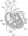
- the heartis a hollow muscular organ having four pumping chambers as seen in Figure 1 : the left and right atria and the left and right ventricles, each provided with its own one-way valve.
- the natural heart valvesare identified as the aortic, mitral (or bicuspid), tricuspid and pulmonary, and are each mounted in an annulus comprising dense fibrous rings attached either directly or indirectly to the atrial and ventricular muscle fibers. Each annulus defines a flow orifice.
- the atriaare the blood-receiving chambers, which pump blood into the ventricles.
- the ventriclesare the blood-discharging chambers.
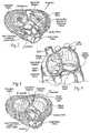
- a wall composed of fibrous and muscular parts, called the interatrial septumseparates the right and left atria (see Figures 2 to 4 ).
- the fibrous interatrial septumis a materially stronger tissue structure compared to the more friable muscle tissue of the heart.
- An anatomic landmark on the interatrial septumis an oval, thumbprint sized depression called the oval fossa, or fossa ovalis (shown in Figure 4 ).
- the synchronous pumping actions of the left and right sides of the heartconstitute the cardiac cycle.
- the cyclebegins with a period of ventricular relaxation, called ventricular diastole.
- the cycleends with a period of ventricular contraction, called ventricular systole.
- the four valvesensure that blood does not flow in the wrong direction during the cardiac cycle; that is, to ensure that the blood does not back flow from the ventricles into the corresponding atria, or back flow from the arteries into the corresponding ventricles.
- the mitral valveis between the left atrium and the left ventricle, the tricuspid valve between the right atrium and the right ventricle, the pulmonary valve is at the opening of the pulmonary artery, and the aortic valve is at the opening of the aorta.
- FIGS 2 and 3show the anterior (A) portion of the mitral valve annulus abutting the non-coronary leaflet of the aortic valve.
- the mitral valve annulusis in the vicinity of the circumflex branch of the left coronary artery, and the posterior (P) side is near the coronary sinus and its tributaries.
- the mitral and tricuspid valvesare defined by fibrous rings of collagen, each called an annulus, which forms a part of the fibrous skeleton of the heart.
- the annulusprovides peripheral attachments for the two cusps or leaflets of the mitral valve (called the anterior and posterior cusps) and the three cusps or leaflets of the tricuspid valve.
- the free edges of the leafletsconnect to chordae tendineae from more than one papillary muscle, as seen in Figure 1 . In a healthy heart, these muscles and their tendinous chords support the mitral and tricuspid valves, allowing the leaflets to resist the high pressure developed during contractions (pumping) of the left and right ventricles.
- Various surgical techniquesmay be used to repair a diseased or damaged valve.
- the damaged leafletsare excised and the annulus sculpted to receive a replacement valve.
- aortic stenosis and other heart valve diseasesthousands of patients undergo surgery each year wherein the defective native heart valve is replaced by a prosthetic valve, either bioprosthetic or mechanical.
- Another less drastic method for treating defective valvesis through repair or reconstruction, which is typically used on minimally calcified valves.
- the problem with surgical therapyis the significant insult it imposes on these chronically ill patients with high morbidity and mortality rates associated with surgical repair.
- valve-lung machinecardiopulmonary bypass
- the diseased native valve leafletsare excised and a prosthetic valve is sutured to the surrounding tissue at the valve annulus.
- some patientsdo not survive the surgical procedure or die shortly thereafter. It is well known that the risk to the patient increases with the amount of time required on extracorporeal circulation. Due to these risks, a substantial number of patients with defective valves are deemed inoperable because their condition is too frail to withstand the procedure. By some estimates, about 30 to 50% of the subjects suffering from aortic stenosis who are older than 80 years cannot be operated on for aortic valve replacement.
- a prosthetic valveis configured to be implanted in a much less invasive procedure by way of catheterization.
- U.S. Patent No. 5,411,552 to Andersen et al.describes a collapsible valve percutaneously introduced in a compressed state through a catheter and expanded in the desired position by balloon inflation.
- a prosthetic valvecan be surgically implanted in a body channel in a more efficient procedure that reduces the time required on extracorporeal circulation. It is desirable that such a device and method be capable of helping patients with defective valves that are deemed inoperable because their condition is too frail to withstand a lengthy conventional surgical procedure.
- the present inventionaddresses these needs and others.
- Various embodiments of the present applicationprovide prosthetic valves and methods of use for replacing a defective native valve in a human heart. Certain embodiments are particularly well adapted for use in a surgical procedure for quickly and easily replacing a heart valve while minimizing time using extracorporeal circulation (i.e., bypass pump).
- a method for treating a native aortic valve in a human heart to replaces the function of the aortic valvecomprises: 1) accessing a native valve through an opening in a chest; 2) advancing an expandable base stent to the site of a native aortic valve, the base stent being radially compressed during the advancement; 3) radially expanding the base stent at the site of the native aortic valve; 4) advancing a valve component within a lumen of the base stent; and 5) expanding a coupling stent on the valve component to mechanically couple to the base stent in a quick and efficient manner.
- the base stentmay comprise a metallic frame.
- at least a portion of the metallic frameis made of stainless steel.
- at least a portion of the metallic frameis made of a shape memory material.
- the valve membermay take a variety of forms.
- the valve componentcomprises biological tissue.
- the metallic frameis viewed under fluoroscopy during advancement of the prosthetic valve toward the native aortic valve.
- the native valve leafletsmay be removed before delivering the prosthetic valve.
- the native leafletsmay be left in place to reduce surgery time and to provide a stable base for fixing the base stent within the native valve.
- the native leafletsrecoil inward to enhance the fixation of the metallic frame in the body channel.
- a balloon or other expansion membermay be used to push the valve leaflets out of the way and thereby dilate the native valve before implantation of the base stent.
- the native annulusmay be dilated between 1.5-5 mm from their initial orifice size to accommodate a larger sized prosthetic valve.
- a prosthetic heart valve systemcomprises a base stent adapted to anchor against a heart valve annulus and defining an orifice therein, and a valve component connected to the base stent.
- the valve componentincludes a prosthetic valve defining therein a non-expandable, non-collapsible orifice, and an expandable coupling stent extending from an inflow end thereof.
- the coupling stenthas a contracted state for delivery to an implant position and an expanded state configured for outward connection to the base stent.
- the base stentmay also be expandable with a contracted state for delivery to an implant position adjacent a heart valve annulus and an expanded state sized to contact and anchor against the heart valve annulus.
- the base stent and also the coupling stentare plastically expandable.
- the prosthetic valvecomprises a commercially available valve having a sewing ring, and the coupling stent attaches to the sewing ring.
- the contracted state of the coupling stentmay be conical, tapering down in a distal direction.
- the coupling stentpreferably comprises a plurality of radially expandable struts at least some of which are arranged in rows, wherein the distalmost row has the greatest capacity for expansion from the contracted state to the expanded state.
- the strut row farthest from the prosthetic valvehas alternating peaks and valleys, wherein the base stent includes apertures into which the peaks of the coupling stent may project to interlock the two stents.
- the base stentmay include a plurality of radially expandable struts between axially-oriented struts, wherein at least some of the axially-oriented struts have upper projections that demark locations around the stent.
- a method of delivery and implant of a prosthetic heart valve systemcomprising the steps of:
- the base stentmay be plastically expandable, and the method further comprises advancing the expandable base stent in a contracted state to the implant position, and plastically expanding the base stent to an expanded state in contact with and anchored to the heart valve annulus, in the process increasing the orifice size of the heart valve annulus by at least 10%, or by 1.5-5 mm.
- the prosthetic valve of the valve componentis selected to have an orifice size that matches the increased orifice size of the heart valve annulus.
- the methodmay also include mounting the base stent over a mechanical expander, and deploying the base stent at the heart valve annulus using the mechanical expander.
- One embodiment of the methodfurther includes mounting the valve component on a holder having a proximal hub and lumen therethrough.
- the holdermounts on the distal end of a handle having a lumen therethrough, and the method including passing a balloon catheter through the lumen of the handle and the holder and within the valve component, and inflating a balloon on the balloon catheter to expand the coupling stent.
- the valve component mounted on the holdermay be packaged separately from the handle and the balloon catheter.
- the contracted state of the coupling stentis conical, and the balloon on the balloon catheter has a larger distal expanded end than its proximal expanded end so as to apply greater expansion deflection to the coupling stent than to the prosthetic valve.
- the coupling stentmay comprise a plurality of radially expandable struts at least some of which are arranged in rows, wherein the row farthest from the prosthetic valve has the greatest capacity for expansion from the contracted state to the expanded state.
- the methodmay employ a coupling stent with a plurality of radially expandable struts, wherein a row farthest from the prosthetic valve has alternating peaks and valleys.
- the distal end of the coupling stentthus expands more than the rest of the coupling stent so that the peaks in the row farthest from the prosthetic valve project outward into apertures in the base stent.
- Both the base stent and the coupling stentmay have a plurality of radially expandable struts between axially-oriented struts, wherein the method includes orienting the coupling stent so that its axially-oriented struts are out of phase with those of the base stent to increase retention therebetween.
- a system for delivering a valve componentincluding a prosthetic valve having a non-expandable, non-collapsible orifice, and an expandable coupling stent extending from an inflow end thereof, the coupling stent having a contracted state for delivery to an implant position and an expanded state.
- the delivery systemincludes a valve holder connected to a proximal end of the valve component, a balloon catheter having a balloon, and a handle configured to attach to a proximal end of the valve holder and having a lumen for passage of the catheter, wherein the balloon extends distally through the handle, past the holder and through the valve component.
- the prosthetic valveis preferably a commercially available valve having a sewing ring to which the coupling stent attaches.
- the contracted state of the coupling stent in the delivery systemmay be conical, tapering down in a distal direction.
- the balloon catheterfurther may include a generally conical nose cone on a distal end thereof that extends through the valve component and engages a distal end of the coupling stent in its contracted state.
- the handlecomprises a proximal section and a distal section that may be coupled together in series to form a continuous lumen, wherein the distal section is adapted to couple to the hub of the holder to enable manual manipulation of the valve component using the distal section prior to connection with the proximal handle section.
- the balloon catheter and proximal handle sectionare packaged together with the balloon within the proximal section lumen.
- valve component mounted on the holderis packaged separately from the handle and the balloon catheter.
- the present inventionattempts to overcome drawbacks associated with conventional, open-heart surgery, while also adopting some of the techniques of newer technologies which decrease the duration of the treatment procedure.
- the prosthetic heart valves of the present inventionare primarily intended to be delivered and implanted using conventional surgical techniques, including the aforementioned open-heart surgery. There are a number of approaches in such surgeries, all of which result in the formation of a direct access pathway to the particular heart valve annulus.
- a direct access pathwayis one that permits direct (i.e., naked eye) visualization of the heart valve annulus.
- embodiments of the two-stage prosthetic heart valves described hereinmay also be configured for delivery using percutaneous approaches, and those minimally-invasive surgical approaches that require remote implantation of the valve using indirect visualization.
- the exemplary two-stage prosthetic heart valve of the present inventionhas an expandable base stent secured to tissue in the appropriate location using a balloon or other expansion technique.
- a hybrid valve member that has non-expandable and expandable portionsthen couples to the base stent in a separate or sequential operation.
- the expandable base stentmay simply be radially expanded outward into contact with the implantation site, or may be provided with additional anchoring means, such as barbs.
- the operationmay be carried out using a conventional open-heart approach and cardiopulmonary bypass. In one advantageous feature, the time on bypass is greatly reduced due to the relative speed of implanting the expandable base stent.
- base stentrefers to a structural component of a heart valve that is capable of attaching to tissue of a heart valve annulus.
- the base stents described hereinare most typically tubular stents, or stents having varying shapes or diameters.
- a stentis normally formed of a biocompatible metal wire frame, such as stainless steel or Nitinol.
- Other base stents that could be used with valves of the present inventioninclude rigid rings, spirally-wound tubes, and other such tubes that fit tightly within a valve annulus and define an orifice therethrough for the passage of blood, or within which a valve member is mounted.
- the base stentcould be separate clamps or hooks that do not define a continuous periphery. Although such devices sacrifice some dynamic stability, and speed and ease of deployment, these devices could be configured to work in conjunction with a particular valve member.
- a self-expanding stentmay be crimped or otherwise compressed into a small tube and possesses sufficient elasticity to spring outward by itself when a restraint such as an outer sheath is removed.
- a balloon-expanding stentis made of a material that is substantially less elastic, and indeed must be plastically expanded from the inside out when converting from a compressed diameter to an expanded. It should be understood that the term balloon-expanding stents encompasses plastically-expandable stents, whether or not a balloon is used to actually expand it.
- the material of the stentplastically deforms after application of a deformation force such as an inflating balloon or expanding mechanical fingers. Both alternatives will be described below. Consequently, the term “balloon-expandable stent" should be considered to refer to the material or type of the stent as opposed to the specific expansion means.
- valve memberrefers to that component of a heart valve that possesses the fluid occluding surfaces to prevent blood flow in one direction while permitting it in another.
- various constructions of valve numbersare available, including those with flexible leaflets and those with rigid leaflets or a ball and cage arrangement.
- the leafletsmay be bioprosthetic, synthetic, or metallic.
- a primary focus of the present inventionis a two-stage prosthetic heart valve having a first stage in which a base stent secures to a valve annulus, and a subsequent second stage in which a valve member connects to the base stent. It should be noted that these stages can be done almost simultaneously, such as if the two components were mounted on the same delivery device, or can be done in two separate clinical steps, with the base stent deployed using a first delivery device, and then the valve member using another delivery device. It should also be noted that the term "two-stage” refers to the two primary steps of anchoring structure to the annulus and then connecting a valve member, which does not necessarily limit the valve to just two parts.
- valve membermay be replaced after implantation without replacing the base stent. That is, an easily detachable means for coupling the valve member and base stent may be used that permits a new valve member to be implanted with relative ease.
- Various configurations for coupling the valve member and base stentare described herein.
- expandableis used herein to refer to a component of the heart valve capable of expanding from a first, delivery diameter to a second, implantation diameter.
- An expandable structuretherefore, does not mean one that might undergo slight expansion from a rise in temperature, or other such incidental cause.
- non-expandableshould not be interpreted to mean completely rigid or a dimensionally stable, as some slight expansion of conventional "non-expandable" heart valves, for example, may be observed.
- body channelis used to define a blood conduit or vessel within the body.
- prosthetic heart valvedetermines the body channel at issue.
- An aortic valve replacementfor example, would be implanted in, or adjacent to, the aortic annulus.
- a mitral valve replacementwill be implanted at the mitral annulus.
- Figures 5A-5Hare sectional views through an isolated aortic annulus AA showing a portion of the adjacent left ventricle LV and ascending aorta with sinus cavities S. The two coronary sinuses CS are also shown.
- the series of viewsshow snapshots of a number of steps in deployment of an exemplary prosthetic heart valve system of the present invention, which comprises a two-component system.
- a first componentis a base stent that is deployed against the native leaflets or, if the leaflets are excised, against the debrided aortic annulus AA.
- a second valve componentfits within the base stent and anchors thereto.
- Figure 5Ashows a catheter 20 having a balloon 22 in a deflated state near a distal end with a tubular base stent 24 crimped thereover.
- the stent 24is shown in a radially constricted, undeployed configuration.
- the catheter 20has been advanced to position the base stent 24 so that it is approximately axially centered at the aortic annulus AA.
- Figure 5Bshows the balloon 22 on the catheter 20 inflated to expand and deploy the base stent 24 against the aortic annulus AA
- Figure 5Cshows the deployed base stent in position after deflation of the balloon 22 and removal of the catheter 20.
- the stent 24provides a base within and against a body lumen (e.g., a valve annulus).
- a body lumene.g., a valve annulus
- the base stent 24comprises a plastically-expandable cloth-covered stainless-steel tubular stent.
- LVOTleft ventricular outflow tract
- the present inventioncould also use a self-expanding base stent 24 which is then reinforced by the subsequently implanted valve component 30. Because the valve component 30 has a non-compressible part, the prosthetic valve 34, and desirably a plastically-expandable coupling stent 36, it effectively resists recoil of the self-expanded base stent 24.
- the stent 24has a diameter sized to be deployed at the location of the native valve (e.g., along the aortic annulus). A portion of the stent 24 may expand outwardly into the respective cavity adjacent the native valve. For example, in an aortic valve replacement, an upper portion may expand into the area of the sinus cavities just downstream from the aortic annulus. Of course, care should be taken to orient the stent 24 so as not to block the coronary openings.
- the stent bodyis preferably configured with sufficient radial strength for pushing aside the native leaflets and holding the native leaflets open in a dilated condition.
- the native leafletsprovide a stable base for holding the stent, thereby helping to securely anchor the stent in the body.
- the lower portionmay be configured with anchoring members, such as, for example, hooks or barbs (not shown).
- the prosthetic valve systemincludes a valve component that may be quickly and easily connected to the stent 24.
- the base stents described hereincan be a variety of designs, including having the diamond/chevron-shaped openings shown or other configurations.
- the materialdepends on the mode of delivery (i.e., balloon- or self-expanding), and the stent can be bare strut material or covered to promote ingrowth and/or to reduce paravalvular leakage.
- a suitable cover that is often usedis a sleeve of fabric such as Dacron.
- the base stent 24may take a number of different configurations as long as it does not require the time-consuming process of suturing it to the annulus.
- another possible configuration for the base stent 24is one that is not fully expandable like the tubular stent as shown. That is, the base stent 24 may have a non-expandable ring-shaped orifice from which an expandable skirt stent or series of anchoring barbs deploy.
- FIG. 5Dshows a valve component 30 mounted on a balloon catheter 32 advancing into position within the base stent 24.
- the valve component 30comprises a prosthetic valve 34 and a coupling stent 36 attached to and projecting from a distal end thereof.
- the coupling stent 36assumes a conical inward taper in the distal direction.
- the catheter 32extends through the valve component 30 and terminates in a distal nose cone 38 which has a conical or bell-shape and covers the tapered distal end of the coupling stent 36.
- the catheter 32extends through an introducing cannula and valve holder.
- the prosthetic valve 34When used for aortic valve replacement, the prosthetic valve 34 preferably has three flexible leaflets which provide the fluid occluding surfaces to replace the function of the native valve leaflets.
- the valve leafletsmay be taken from another human heart (cadaver), a cow (bovine), a pig (porcine valve) or a horse (equine).
- the valve membermay comprise mechanical components rather than biological tissue.
- the three leafletsare supported by three commissural posts. A ring is provided along the base portion of the valve member.
- the prosthetic valve 34partly comprises a commercially available, non-expandable prosthetic heart valve, such as the Carpentier-Edwards PERIMOUNT Magna® Aortic Heart Valve available from Edwards Lifesciences of Irvine, California.
- a "commercially available" prosthetic heart valveis an off-the-shelf (i.e., suitable for stand-alone sale and use) prosthetic heart valve defining therein a non-expandable, non-collapsible orifice and having a sewing ring capable of being implanted using sutures through the sewing ring in an open-heart, surgical procedure.
- non-expandable and non-collapsibleshould not be interpreted to mean completely rigid and dimensionally stable, merely that the valve is not expandable/collapsible like some proposed minimally-invasively or percutaneously-delivered valves.
- An implant proceduretherefore involves first delivering and expanding the base stent 24 at the aortic annulus, and then coupling the valve component 30 including the valve 34 thereto. Because the valve 34 is non-expandable, the entire procedure is typically done using the conventional open-heart technique. However, because the base stent 24 is delivered and implanted by simple expansion, and then the valve component 30 attached thereto by expansion, both without suturing, the entire operation takes less time. This hybrid approach will also be much more comfortable to surgeons familiar with the open-heart procedures and commercially available heart valves.
- valve component 30Even if the system must be validated through clinical testing to satisfy the Pre-Market Approval (PMA) process with the FDA (as opposed to a 510k submission), the acceptance of the valve component 30 at least will be greatly streamlined with a commercial heart valve that is already approved, such as the Magna® Aortic Heart Valve.
- PMAPre-Market Approval
- the prosthetic valve 34is provided with an expandable coupling mechanism in the form of the coupling stent 36 for securing the valve to the base stent 24.
- an expandable coupling mechanismin the form of the coupling stent 36 for securing the valve to the base stent 24.
- the coupling stent 36is shown, the coupling mechanism may take a variety of different forms, but eliminates the need for connecting sutures and provides a rapid connection means.
- the prosthetic valve 34may include a suture-permeable ring 42 that desirably abuts the aortic annulus AA. More preferably, the sewing ring 42 is positioned supra-annularly, or above the narrowest point of the aortic annulus AA, so as to allow selection of a larger orifice size than a valve placed intra-annularly. With the aforementioned annulus expansion using the base stent 24, and the supra-annular placement, the surgeon may select a valve having a size one or two increments larger than previously conceivable.
- the prosthetic valve 34is desirably a commercially available heart valve having a sewing ring 42.
- the balloon catheter 32has advanced relative to the valve component 30 to displace the nose cone 38 out of engagement with the coupling stent 36.
- a dilatation balloon 40 on the catheter 30can be seen just beyond the distal end of the coupling stent 36.
- Figure 5Fshows the balloon 40 on the catheter 32 inflated to expand and deploy the coupling stent 36 against the base stent 24.
- the balloon 40is desirably inflated using controlled, pressurized, sterile physiologic saline.
- the coupling stent 36transitions between its conical contracted state and its generally tubular expanded state. Simple interference between the coupling stent 36 and the base stent 24 may be sufficient to anchor the valve component 30 within the base stent, or interacting features such as projections, hooks, barbs, fabric, etc. may be utilized.
- a higher strength stent (self-or balloon-expandable) configurationmay be used.
- a relatively robust base stent 24may be used to push the native leaflets aside, and the absent valve component 30 is not damaged or otherwise adversely affected during the high-pressure base stent deployment.
- the valve component 30connects thereto by deploying the coupling stent 36, which may be somewhat more lightweight requiring smaller expansion forces.
- the balloon 40may have a larger distal expanded end than its proximal expanded end so as to apply more force to the coupling stent 36 than to the prosthetic valve 34.
- the prosthetic valve 34 and flexible leaflets thereinare not subject to high expansion forces from the balloon 40.
- the coupling stent 36may also be a self-expanding type of stent.
- the nose cone 38is adapted to retain the coupling stent 36 in its constricted state prior to position in the valve component 30 within the base stent 24.
- the base stents described hereincould include barbs or other tissue anchors to further secure the stent to the tissue, or to secure the coupling stent 36 to the base stent 24.
- the barbscould be deployable (e.g., configured to extend or be pushed radially outward) by the expansion of a balloon.
- the coupling stent 36is covered to promote in-growth and/or to reduce paravalvular leakage, such as with a Dacron tube or the like.
- Figure 5Gshows the deflated balloon 40 on the catheter 32 along with the nose cone 38 being removed from within the valve component 30.
- Figure 5Hshows the fully deployed prosthetic heart valve system of the present invention including the valve component 30 coupled to the base stent 24 within the aortic annulus AA.
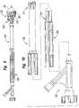
- FIG 6is an exploded view, and Figures 7 and 8 are assembled views, of an exemplary system 50 for delivering the prosthetic heart valve of the present invention. Modified components of the delivery system 50 are also shown in Figures 9 and 10 .
- the delivery system 50includes a balloon catheter 52 having the balloon 40 on its distal end and an obturator 54 on a proximal end.
- the obturator 54presents a proximal coupling 56 that receives a luer connector or other such fastener of a Y-fitting 58.
- the aforementioned nose cone 38may attach to the distalmost end of the catheter 52, but more preferably attaches to a wire (not shown) inserted through the center lumen of the balloon catheter 52.
- the catheter 52 and the nose cone 38pass through a hollow handle 60 having a proximal section 62 and a distal section 64.
- a distal end of the distal handle section 64firmly attaches to a hub 66 of a valve holder 68, which in turn attaches to the prosthetic heart valve component 30. Details of the valve holder 68 will be given below with reference to Figures 11A-11E .
- the two sections 62, 64 of the handle 60are desirably formed of a rigid material, such as a molded plastic, and coupled to one another to form a relatively rigid and elongated tube for manipulating the prosthetic valve component 30 attached to its distal end.
- the distal section 64may be easily coupled to the holder hub 66 and therefore provide a convenient tool for managing the valve component 30 during pre-surgical rinsing steps.
- the distal section 64features a distal tubular segment 70 that couples to the holder hub 66, and an enlarged proximal segment 72 having an opening on its proximal end that receives a tubular extension 74 of the proximal handle section 62.
- Figure 6shows an O-ring 76 that may be provided on the exterior of the tubular extension 74 for a frictional interference fit to prevent the two sections from disengaging.
- the distal tubular segment 70may also have an O-ring for firmly coupling to the holder hub 66, or may be attached with threading or the like.
- the balloon 40 on the catheter 52is packaged within the proximal handle section 62 for protection and ease of handling. Coupling the proximal and distal handle sections 62, 64 therefore "loads" the system 50 such that the balloon catheter 52 may be advanced through the continuous lumen leading to the valve component 30.
- Figures 9 and 10illustrate a delivery system 50 similar to that shown in Figure 7 , but with alternative couplers 77 on both the proximal and distal handle sections 62, 64 in the form of cantilevered teeth that snap into complementary recesses formed in the respective receiving apertures. Likewise, threading on the mating parts could also be used, as well as other similar expedients.
- Figure 9shows the balloon 40 inflated to expand the valve component coupling stent 36.
- the prosthetic valve component 30incorporates bioprosthetic tissue leaflets and is packaged and stored attached to the holder 68 but separate from the other introduction system 50 components.
- bioprosthetic tissueis packaged and stored in a jar with preservative solution for long shelf life, while the other components are packaged and stored dry.
- an elongated lumen(not numbered) extends from the proximal end of the Y-fitting 58 to the interior of the balloon 40.
- the Y-fitting 58desirably includes an internally threaded connector 80 for attachment to an insufflation system, or a side port 82 having a luer fitting 84 or similar expedient may be used for insufflation of the balloon 40.
- Figures 7 and 8show two longitudinal positions of the catheter 52 and associated structures relative to the handle 60 and its associated structures.
- the balloon 40primarily resides within the distal handle section 64.
- Figure 7illustrates the delivery configuration of the introduction system 50, in which the surgeon advances the prosthetic valve component 30 from outside the body into a location adjacent the target annulus.
- the nose cone 38extends around and protects a distal end of the conical undeployed coupling stent 36. This configuration is also seen in Figure 5D , albeit with the holder 68 removed for clarity. Note the spacing S between the proximal coupling 56 and the proximal end of the handle 60.
- the surgeonadvances the prosthetic valve component 30 into its desired implantation position at the valve annulus, and then advances the balloon 40 through the valve component and inflates it.
- the operatorconverts the delivery system 50 from the retracted configuration of Figure 7 to the deployment configuration of Figure 8 , with the balloon catheter 40 displaced distally as indicated by the arrow 78 to disengage the nose cone 38 from the coupling stent 36.
- the proximal coupling 56now contacts the proximal end of the handle 60, eliminating the space S indicated in Figure 7 .
- the prosthetic valve component 30may be implanted at the valve annulus with a pre-deployed base stent 24, as explained above, or without.
- the coupling stent 36may be robust enough to anchor the valve component 30 directly against the native annulus (with or without leaflet excision) in the absence of the base stent 24. Consequently, the description of the system 50 for introducing the prosthetic heart valve should be understood in the context of operating with or without the pre-deployed base stent 24.
- valve component 30Prior to a further description of operation of the delivery system 50, a more detailed explanation of the valve component 30 and valve holder 68 is necessary.
- Figures 11A-11Eshow a number of perspective and other views of the exemplary valve component 30 mounted on the delivery holder 68 of the present invention.
- the valve component 30comprises the prosthetic valve 34 having the coupling stent 36 attached to an inflow end thereof.
- the prosthetic valve 34comprises a commercially available off-the-shelf non-expandable, non-collapsible commercial prosthetic valve. Any number of prosthetic heart valves can be retrofit to attach the coupling stent 36, and thus be suitable for use in the context of the present invention.
- the prosthetic valve 34may be a mechanical valve or a valve with flexible leaflets, either synthetic or bioprosthetic. In a preferred embodiment, however, the prosthetic valve 34 includes bioprosthetic tissue leaflets 86 ( Figure 11A ). Furthermore, as mentioned above, the prosthetic valve 34 is desirably a Carpentier-Edwards PERIMOUNT Magna® Aortic Heart Valve (e.g., model 3000TFX) available from Edwards Lifesciences of Irvine, California.
- Carpentier-Edwards PERIMOUNT Magna® Aortic Heart Valvee.g., model 3000TFX
- the coupling stent 36preferably attaches to the ventricular (or inflow) aspect of the valve's sewing ring 42 during the manufacturing process in a way that preserves the integrity of the sewing ring and prevents reduction of the valve's effective orifice area (EOA).
- EOAeffective orifice area
- the coupling stent 36will be continuously sutured to sewing ring 42 in a manner that maintains the outer contours of the sewing ring.
- Suturesmay be passed through apertures or eyelets in the stent skeleton, or through a cloth covering that in turn is sewn to the skeleton.
- Other connection solutionsinclude prongs or hooks extending inward from the stent, ties, Velcro, snaps, adhesives, etc.
- the coupling stent 36may be more rigidly connected to rigid components within the prosthetic valve 34.
- the surgeoncan seat the sewing ring 42 against the annulus in accordance with a conventional surgery. This gives the surgeon familiar tactile feedback to ensure that the proper patient-prosthesis match has been achieved.
- placement of the sewing ring 42 against the outflow side of the annulushelps reduce the probability of migration of the valve component 30 toward the ventricle.
- the coupling stent 36may be a pre-crimped, tapered, 316L stainless steel balloon-expandable stent, desirably covered by a polyester skirt 88 to help seal against paravalvular leakage and promote tissue ingrowth once implanted within the base stent 24 (see Figure 5F ).
- the coupling stent 36transitions between the tapered constricted shape of Figures 11A-11E to its flared expanded shape shown in Figure 5F , and also in Figure 10 .
- the coupling stent 36desirably comprises a plurality of sawtooth-shaped or otherwise angled, serpentine or web-like struts 90 connected to three generally axially-extending posts 92.
- the posts 92desirably feature a series of evenly spaced apertures to which sutures holding the polyester skirt 88 in place may be anchored.
- the stent 36 when expandedflares outward and conforms closely against the inner surface of the base stent 24, and has an axial length substantially the same as the base stent.
- Anchoring devicessuch as barbs or other protruberances from the coupling stent 36 may be provided to enhance the frictional hold between the coupling stent and the base stent 24.
- both the base stent 24 and the coupling stent 36are desirably plastically-expandable to provide a firmer anchor for the valve 34; first to the annulus with or without native leaflets, and then between the two stents.
- the stentsmay be expanded using a balloon or mechanical expander as described below.
- the holder 68comprises the aforementioned proximal hub 66 and a thinner distal extension 94 thereof forming a central portion of the holder.
- Three legs 96a, 96b, 96c circumferentially equidistantly spaced around the central extension 94 and projecting radially outward therefromcomprise inner struts 98 and outer commissure rests 100.
- the prosthetic valve 34preferably includes a plurality, typically three, commissures 102 that project in an outflow direction.
- the commissure rests 100preferably incorporate depressions into which fit the tips of the commissures 102.
- the holder 68is formed of a rigid polymer such as Delrin or polypropylene that is transparent to increase visibility of an implant procedure. As best seen in Figure 11E , the holder 68 exhibits openings between the legs 96a, 96b, 96c to provide a surgeon good visibility of the valve leaflets 86, and the transparency of the legs further facilitates visibility and permits transmission of light therethrough to minimize shadows.
- Figure 11Ealso illustrate a series of through holes in the legs 96a, 96b, 96c permitting connecting sutures to be passed through fabric in the prosthetic valve 34 and across a cutting guide in each leg. As is known in the art, severing a middle length of suture that is connected to the holder 68 and passes through the valve permits the holder to be pulled free from the valve when desired.
- FIGS 11C and 11illustrate a somewhat modified coupling stent 36 from that shown in Figures 11A and 11B , wherein the struts 90 and axially-extending posts 92 are better defined.
- the posts 92are somewhat wider and more robust than the struts 90, as the latter provide the stent 36 with the ability to expand from the conical shape shown to a more tubular configuration.
- a generally circular reinforcing ring 104abuts the valve sewing ring 42.
- Both the posts 92 and the ring 104further include a series of through holes 106 that may be used to secure the polyester skirt 88 to the stent 36 using sutures or the like.
- a number of variants of the coupling stent 36are also described below.
- Figures 12A-12Billustrate the exemplary coupling stent 36 in both a flat configuration (12A) and a tubular configuration (12B) that is generally the expanded shape.
- the web-like struts 90 and a reinforcing ring 104connect three generally axially-extending posts 92.
- a plurality of evenly spaced apertures 106provide anchors for holding the polyester skirt 88 (see Figure 11B ) in place.
- the web-like struts 90also include a series of axially-extending struts 108.
- an upper end of the coupling stent 36 that connects to the sewing ring of the valve and is defined by the reinforcing ring 104follows an undulating path with alternating arcuate troughs 110 and peaks 112.
- the exemplary prosthetic valve 34has an undulating sewing ring 42 to which the upper end of the coupling stent 36 conforms.
- the geometry of the stent 36matches that of the undulating sewing ring 42.
- the tubular version of Figure 12Bis an illustration of an expanded configuration, although the balloon 40 may over-expand the free (lower) end of the stent 36 such that it ends up being slightly conical.
- Figures 13A and 13Bshow an alternative coupling stent 120, again in flattened and tubular configurations, respectively.
- the coupling stent 120includes web-like struts 122 extending between a series of axially-extending struts 124.
- all of the axially-extending struts 124are substantially the same thin cross-sectional size.
- the upper or connected end of the stent 120again includes a reinforcing ring 126, although this version is interrupted with a series of short lengths separated by gaps.
- the upper enddefines a plurality of alternating troughs 128 and peaks 130, with lengths of the reinforcing ring 126 defining the peaks.
- the axially-extending struts 124are in-phase with the scalloped shape of the upper end of the stent 120, and coincide with the peaks and the middle of the troughs.
- the gaps between the lengths making up the reinforcing ring 126permit the stent 120 to be matched with a number of different sized prosthetic valves 34. That is, the majority of the stent 120 is expandable having a variable diameter, and providing gaps in the reinforcing ring 126 allows the upper end to also have a variable diameter so that it can be shaped to match the size of the corresponding sewing ring. This reduces manufacturing costs as correspondingly sized stents need not be used for each different sized valve.
- Figure 14is a plan view of a still further alternative coupling stent 132 that is very similar to the coupling stent 120, including web-like struts 134 connected between a series of axially-extending struts 136, and the upper end is defined by a reinforcing ring 138 formed by a series of short lengths of struts.
- the peaks of the undulating upper endhave gaps as opposed to struts.
- the axially-extending struts 136are out-of-phase with the scalloped shape of the upper end of the stent 132, and do not correspond to the peaks and the middle of the troughs.
- Figure 15illustrates an exemplary coupling stent 140 again having the expandable struts 142 between the axially-extending struts 144, and an upper reinforcing ring 146.
- the axially-extending struts 144are in-phase with peaks and troughs of the upper end of the stent.
- the reinforcing ring 146is a cross between the earlier-described such rings as it is continuous around its periphery but also has a variable diameter. That is, the ring 146 comprises a series of lengths of struts 148 of fixed length connected by thinner bridge portions 150 of variable length.
- the bridge portions 150are each formed with a radius so that they can be either straightened (lengthened) or bent more (compressed).
- a series of apertures 152are also formed in an upper end of the stent 142 provide anchor points for sutures or other attachment means when securing the stent to the sewing ring of the corresponding prosthetic valve.
- an alternative coupling stent 154is identical to the stent 140 of Figure 15 , although the axially-extending struts 156 are out-of-phase with the peaks and troughs of the undulating upper end.
- Figure 17shows a still further variation on a coupling stent 160, which has a series of expandable struts 162 connecting axially-extending struts 164.
- the web-like struts 162also include a series of axially-extending struts 166, although these are thinner than the main axial struts 164.
- a reinforcing ring 168is also thicker than the web-like struts 162, and features one or more gaps 170 in each trough such that the ring is discontinuous and expandable.
- Barbs 172, 174 on the axially extending struts 164, 166may be utilized to enhance retention between the coupling stent 160 and a base stent with which it cooperates, or with annular tissue in situations where there is no base stent, as explained above.
- the two-component valve systems described hereinutilize an outer or base stent (such as base stent 24) and a valve component having an inner or valve stent (such as coupling stent 36).
- the valve and its stentadvance into the lumen of the pre-anchored outer stent and the valve stent expands to join the two stents and anchor the valve into its implant position.
- a number of variations of coupling stent that attach to the valve componenthave been shown and described above.
- Figures 18-20illustrate exemplary base stents and cooperation between the two stents.
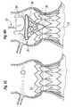
- Figures 18A and 18Bshow an exemplary embodiment of a base stent 180 comprising a plurality of radially-expandable struts 182 extending between a plurality of generally axially-extending struts 184.
- the struts 182form chevron patterns between the struts 184, although other configurations such as serpentine or diamond-shaped could also be used.
- the top and bottom rows of the radially-expandable struts 182are arranged in apposition so as to form a plurality of triangular peaks 186 and troughs 188.
- the axial struts 184are in-phase with the troughs 188.
- the flattened view of Figure 18Ashows four axial projections 190 that each extend upward from one of the axial struts 184.
- the exemplary base stent 180desirably has three evenly circumferentially spaced projections, as seen around the periphery in the tubular version of Figure 18B , providing location markers for the base stent. These markers thus make it easier for the surgeon to orient the stent 180 such that the markers align with the native commissures.
- the visible projections 190provide reference marks such that the inner stent can be properly oriented within the base stent.
- the projections 190may be differently colored than the rest of the stent 180, or have radiopaque indicators thereon.
- the length of the projections 190 above the upper row of middle struts 182may also be calibrated to help the surgeon axially position the stent 180. For example, the distance from the tips of the projections 190 to the level of the native annulus could be determined, and the projections 190 located at a particular anatomical landmark such as just below the level of the coronary ostia.
- An undulating dashed line 192 in Figure 18Arepresents the upper end of the inner or coupling stent 140, which is shown in phantom superimposed over the base stent 180.
- the dashed line 192also represents an undulating sewing ring, and it bears repeating that the sewing ring could be planar such that the upper end of the coupling stent is also planar.
- the coupling stent 140includes axially-extending struts that are in-phase with the respective peaks and troughs of the scalloped upper end of the stent.
- the peaks of the scalloped upper end of the coupling stentcorrespond rotationally (are in-phase) with the axial struts 184 that have the projections 190. Therefore, because the coupling stent 140 axial struts are in-phase with the peaks of the upper end thereof, they are also in-phase with the axial struts 184 of the base stent 180. Conversely, a coupling stent may have axial struts out-of-phase with peaks of the upper end thereof, in which case the respective axial struts of the two stents are also out-of-phase.
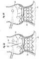
- Figure 19shows an alternative base stent 200 that generally has the same components as the base stent 180 of Figure 18A , but the axial struts 184 extend between the peaks 186 of the outer rows of middle struts 182. In the earlier embodiment, the axial struts 184 extended between the troughs 188.
- the coupling stent 154 of Figure 16is shown in phantom superimposed over the base stent 200 to illustrate how the axial struts of the two stents are now out-of-phase to increase interlocking therebetween.
- the stent 200also exhibits different rows of middle struts 182. Specifically, a first row 202a defines V's having relatively shallow angles, a second row 202b defines V's with medium angles, and a third row 202c defined V's with more acute angles.
- the different angles formed by the middle struts 182 in these rowshelps shape the stent into a conical form when expanded.
- the struts in the third row 202cwhich is farthest from the prosthetic valve have the greatest capacity for expansion to accommodate the transition from the collapsed conical shape of the stent to the expanded tubular shape.
- the peaks and troughs of the web-like expandable struts on the two stentscould be oriented out-of-phase or in-phase.
- the peaks and troughs of the two stentsare out of phase so that expansion of the inner stent causes its peaks to deform outwardly into the troughs of the outer stent, and thereby provide interlocking structure therebetween.
- the variations described aboveprovide a number of permutations of this cooperation.
- axial projections on one or both of stentscould be bent to provide an interference with the other stent.
- the lower ends of the axial struts 108 in the stent 36 shown in Figure 12Acould be bent outward by expansion of a non-uniform shaped balloon such that they extend in voids within the outer stent.
- the embodiment of Figure 17illustrates barbs 172, 174 that can be bent outward into interference with the corresponding base stent.
- Strut ends or barbs that transition from one position to another to increase retention between the two stentscan be actuated by mechanical bending, such as with a balloon, or through an automatic shape change upon installation within the body.
- some shape memory alloyssuch as Nitinol can be designed to undergo a shape change upon a temperature change, such that they assume a first shape at room temperature, and a second shape at body temperature.
- Figure 20illustrates a simplified means for increasing retention between the two stents.
- An inner valve stent 210fits within an outer base stent 212 such that a lower end 214 thereof extends below the outer stent.
- the lower end 214is caused to bend or wrap outward to prevent relative upward movement of the inner stent within the outer stent.
- Figure 21is a perspective view of a device 220 for delivering and expanding a base stent 222 with a mechanical expander 224.
- the expander 224includes a plurality of spreadable fingers 226 over which the base stent 22 is crimped.
- the device 220includes a syringe-like apparatus including a barrel 230 within which a plunger 232 linearly slides.
- the fingers 226are axially fixed but capable of pivoting or flexing with respect to the barrel 230.
- the distal end of the plunger 232has an outer diameter that is greater than the diameter circumscribed by the inner surfaces of the spreadable fingers 226.
- proximal lead-in rampon the inside of the fingers 226 such that distal movement of the plunger 232 with respect to the barrel 230 gradually cams the fingers outward.
- the two positions of the plunger 232are shown in Figures 21 and 23 .
- the plunger 232may also be threadingly received within the barrel 230.
- the plunger 232may be formed in two parts freely rotatable with respect to one another, with a proximal part threadingly received within the barrel 230 while a distal part does not rotate with respect to the barrel and merely cams the fingers 226 outward.
- a mechanical linkagemay be used instead of a camming action whereby levers hinged together create outward movement of the fingers 226.
- a hybrid version using an inflatable balloon with mechanical parts mounted on the outside of the balloonmay be utilized.
- the fingers 226have a contoured exterior profile such that they expand the base stent 222 into a particular shape that better fits the heart valve annulus.
- the base stent 222may be expanded into an hourglass shape with wider upper and lower ends and a smaller midsection, and/or an upper end may be formed with a tri-lobular shape to better fit the aortic sinuses.
- the tri-lobular shapeis useful for orienting the base stent 222 upon implant, and also for orienting the coupling stent of the valve component that is received therewithin.
- the two-component valve system illustrated in the preceding figuresprovides a device and method that substantially reduces the time of the surgical procedure as compared with replacement valves that are sutured to the tissue after removing the native leaflets.
- the stent 24 of Figures 5-9may be deployed quickly and the valve component 30 may also be quickly attached to the stent. This reduces the time required on extracorporeal circulation and thereby substantially reduces the risk to the patient.
- the present inventionhaving the pre-anchored stent, within which the valve and its stent mount, permits the annulus to be expanded to accommodate a larger valve than otherwise would be possible.
- LVOTleft ventricular outflow tract
- significantly expanding the LVOTmeans expanding it by at least 10%, more preferably between about 10-30%.
- the LVOTmay be expanded 1.5-5 mm depending on the nominal orifice size. This expansion of the annulus creates an opportunity to increase the size of a surgically implanted prosthetic valve.
- the present inventionemploys a balloon-expandable base stent, and a balloon-expandable valve stent.
- the combination of these two stentspermits expansion of the LVOT at and just below the aortic annulus, at the inflow end of the prosthetic valve.
- the interference fit created between the outside of the base stent and the LVOTsecures the valve without pledgets or sutures taking up space, thereby allowing for placement of the maximum possible valve size.
- a larger valve size than would otherwise be available with conventional surgeryenhances volumetric blood flow and reduces the pressure gradient through the valve.
- embodiments of the present inventionprovide important new devices and methods wherein a valve may be securely anchored to a body lumen in a quick and efficient manner.
- Embodiments of the present inventionprovide a means for implanting a prosthetic valve in a surgical procedure without requiring the surgeon to suture the valve to the tissue. Accordingly, the surgical procedure time is substantially decreased.
- the stentmay be used to maintain the native valve in a dilated condition. As a result, it is not necessary for the surgeon to remove the native leaflets, thereby further reducing the procedure time.
- the present inventionprovides an improved system wherein a valve member may be replaced in a more quick and efficient manner. More particularly, it is not necessary to cut any sutures in order to remove the valve. Rather, the valve member may be disconnected from the stent (or other base stent) and a new valve member may be connected in its place. This is an important advantage when using biological tissue valves or other valves having limited design lives.
Landscapes
- Health & Medical Sciences (AREA)
- Cardiology (AREA)
- Engineering & Computer Science (AREA)
- Biomedical Technology (AREA)
- Vascular Medicine (AREA)
- Transplantation (AREA)
- Oral & Maxillofacial Surgery (AREA)
- Heart & Thoracic Surgery (AREA)
- Life Sciences & Earth Sciences (AREA)
- Animal Behavior & Ethology (AREA)
- General Health & Medical Sciences (AREA)
- Public Health (AREA)
- Veterinary Medicine (AREA)
- Mechanical Engineering (AREA)
- Prostheses (AREA)
- Media Introduction/Drainage Providing Device (AREA)
Abstract
Description
- The present application claims priority under 35 U.S.C. § 119(e) to
U.S. provisional application number 61/139,398 filed December 19, 2008 - The present invention generally relates to prosthetic valves for implantation in body channels. More particularly, the present invention relates to prosthetic heart valves configured to be surgically implanted in less time than current valves.
- In vertebrate animals, the heart is a hollow muscular organ having four pumping chambers as seen in
Figure 1 : the left and right atria and the left and right ventricles, each provided with its own one-way valve. The natural heart valves are identified as the aortic, mitral (or bicuspid), tricuspid and pulmonary, and are each mounted in an annulus comprising dense fibrous rings attached either directly or indirectly to the atrial and ventricular muscle fibers. Each annulus defines a flow orifice. - The atria are the blood-receiving chambers, which pump blood into the ventricles. The ventricles are the blood-discharging chambers. A wall composed of fibrous and muscular parts, called the interatrial septum separates the right and left atria (see
Figures 2 to 4 ). The fibrous interatrial septum is a materially stronger tissue structure compared to the more friable muscle tissue of the heart. An anatomic landmark on the interatrial septum is an oval, thumbprint sized depression called the oval fossa, or fossa ovalis (shown inFigure 4 ). - The synchronous pumping actions of the left and right sides of the heart constitute the cardiac cycle. The cycle begins with a period of ventricular relaxation, called ventricular diastole. The cycle ends with a period of ventricular contraction, called ventricular systole. The four valves (see
Figures 2 and 3 ) ensure that blood does not flow in the wrong direction during the cardiac cycle; that is, to ensure that the blood does not back flow from the ventricles into the corresponding atria, or back flow from the arteries into the corresponding ventricles. The mitral valve is between the left atrium and the left ventricle, the tricuspid valve between the right atrium and the right ventricle, the pulmonary valve is at the opening of the pulmonary artery, and the aortic valve is at the opening of the aorta. Figures 2 and 3 show the anterior (A) portion of the mitral valve annulus abutting the non-coronary leaflet of the aortic valve. The mitral valve annulus is in the vicinity of the circumflex branch of the left coronary artery, and the posterior (P) side is near the coronary sinus and its tributaries.- The mitral and tricuspid valves are defined by fibrous rings of collagen, each called an annulus, which forms a part of the fibrous skeleton of the heart. The annulus provides peripheral attachments for the two cusps or leaflets of the mitral valve (called the anterior and posterior cusps) and the three cusps or leaflets of the tricuspid valve. The free edges of the leaflets connect to chordae tendineae from more than one papillary muscle, as seen in
Figure 1 . In a healthy heart, these muscles and their tendinous chords support the mitral and tricuspid valves, allowing the leaflets to resist the high pressure developed during contractions (pumping) of the left and right ventricles. - When the left ventricle contracts after filling with blood from the left atrium, the walls of the ventricle move inward and release some of the tension from the papillary muscle and chords. The blood pushed up against the under-surface of the mitral leaflets causes them to rise toward the annulus plane of the mitral valve. As they progress toward the annulus, the leading edges of the anterior and posterior leaflet come together forming a seal and closing the valve. In the healthy heart, leaflet coaptation occurs near the plane of the mitral annulus. The blood continues to be pressurized in the left ventricle until it is ejected into the aorta. Contraction of the papillary muscles is simultaneous with the contraction of the ventricle and serves to keep healthy valve leaflets tightly shut at peak contraction pressures exerted by the ventricle.
- Various surgical techniques may be used to repair a diseased or damaged valve. In a valve replacement operation, the damaged leaflets are excised and the annulus sculpted to receive a replacement valve. Due to aortic stenosis and other heart valve diseases, thousands of patients undergo surgery each year wherein the defective native heart valve is replaced by a prosthetic valve, either bioprosthetic or mechanical. Another less drastic method for treating defective valves is through repair or reconstruction, which is typically used on minimally calcified valves. The problem with surgical therapy is the significant insult it imposes on these chronically ill patients with high morbidity and mortality rates associated with surgical repair.
- When the valve is replaced, surgical implantation of the prosthetic valve typically requires an open-chest surgery during which the heart is stopped and patient placed on cardiopulmonary bypass (a so-called "heart-lung machine"). In one common surgical procedure, the diseased native valve leaflets are excised and a prosthetic valve is sutured to the surrounding tissue at the valve annulus. Because of the trauma associated with the procedure and the attendant duration of extracorporeal blood circulation, some patients do not survive the surgical procedure or die shortly thereafter. It is well known that the risk to the patient increases with the amount of time required on extracorporeal circulation. Due to these risks, a substantial number of patients with defective valves are deemed inoperable because their condition is too frail to withstand the procedure. By some estimates, about 30 to 50% of the subjects suffering from aortic stenosis who are older than 80 years cannot be operated on for aortic valve replacement.
- Because of the drawbacks associated with conventional open-heart surgery, percutaneous and minimally-invasive surgical approaches are garnering intense attention. In one technique, a prosthetic valve is configured to be implanted in a much less invasive procedure by way of catheterization. For instance,
U.S. Patent No. 5,411,552 to Andersen et al. describes a collapsible valve percutaneously introduced in a compressed state through a catheter and expanded in the desired position by balloon inflation. Although these remote implantation techniques have shown great promise for treating certain patients, replacing a valve via surgical intervention is still the preferred treatment procedure. One hurdle to the acceptance of remote implantation is resistance from doctors who are understandably anxious about converting from an effective, if imperfect, regimen to a novel approach that promises great outcomes but is relatively foreign. In conjunction with the understandable caution exercised by surgeons in switching to new techniques of heart valve replacement, regulatory bodies around the world are moving slowly as well. Numerous successful clinical trials and follow-up studies are in process, but much more experience with these new technologies will be required before they are completely accepted. - Accordingly, there is a need for an improved device and associated method of use wherein a prosthetic valve can be surgically implanted in a body channel in a more efficient procedure that reduces the time required on extracorporeal circulation. It is desirable that such a device and method be capable of helping patients with defective valves that are deemed inoperable because their condition is too frail to withstand a lengthy conventional surgical procedure. The present invention addresses these needs and others.
- Various embodiments of the present application provide prosthetic valves and methods of use for replacing a defective native valve in a human heart. Certain embodiments are particularly well adapted for use in a surgical procedure for quickly and easily replacing a heart valve while minimizing time using extracorporeal circulation (i.e., bypass pump).
- In one embodiment, a method for treating a native aortic valve in a human heart to replaces the function of the aortic valve, comprises: 1) accessing a native valve through an opening in a chest; 2) advancing an expandable base stent to the site of a native aortic valve, the base stent being radially compressed during the advancement; 3) radially expanding the base stent at the site of the native aortic valve; 4) advancing a valve component within a lumen of the base stent; and 5) expanding a coupling stent on the valve component to mechanically couple to the base stent in a quick and efficient manner.
- In one variation, the base stent may comprise a metallic frame. In one embodiment, at least a portion of the metallic frame is made of stainless steel. In another embodiment, at least a portion of the metallic frame is made of a shape memory material. The valve member may take a variety of forms. In one preferred embodiment, the valve component comprises biological tissue. In another variation of this method, the metallic frame is viewed under fluoroscopy during advancement of the prosthetic valve toward the native aortic valve.
- The native valve leaflets may be removed before delivering the prosthetic valve. Alternatively, the native leaflets may be left in place to reduce surgery time and to provide a stable base for fixing the base stent within the native valve. In one advantage of this method, the native leaflets recoil inward to enhance the fixation of the metallic frame in the body channel. When the native leaflets are left in place, a balloon or other expansion member may be used to push the valve leaflets out of the way and thereby dilate the native valve before implantation of the base stent. The native annulus may be dilated between 1.5-5 mm from their initial orifice size to accommodate a larger sized prosthetic valve.
- In accordance with a preferred aspect, a prosthetic heart valve system comprises a base stent adapted to anchor against a heart valve annulus and defining an orifice therein, and a valve component connected to the base stent. The valve component includes a prosthetic valve defining therein a non-expandable, non-collapsible orifice, and an expandable coupling stent extending from an inflow end thereof. The coupling stent has a contracted state for delivery to an implant position and an expanded state configured for outward connection to the base stent. The base stent may also be expandable with a contracted state for delivery to an implant position adjacent a heart valve annulus and an expanded state sized to contact and anchor against the heart valve annulus. Desirably, the base stent and also the coupling stent are plastically expandable.
- In one embodiment, the prosthetic valve comprises a commercially available valve having a sewing ring, and the coupling stent attaches to the sewing ring. The contracted state of the coupling stent may be conical, tapering down in a distal direction. The coupling stent preferably comprises a plurality of radially expandable struts at least some of which are arranged in rows, wherein the distalmost row has the greatest capacity for expansion from the contracted state to the expanded state. Still further, the strut row farthest from the prosthetic valve has alternating peaks and valleys, wherein the base stent includes apertures into which the peaks of the coupling stent may project to interlock the two stents. The base stent may include a plurality of radially expandable struts between axially-oriented struts, wherein at least some of the axially-oriented struts have upper projections that demark locations around the stent.
- A method of delivery and implant of a prosthetic heart valve system is also disclosed herein, comprising the steps of:
- advancing a base stent to an implant position adjacent a heart valve annulus;
- anchoring the base stent to the heart valve annulus;
- providing a valve component including a prosthetic valve having a non-expandable, non-collapsible orifice, the valve component further including an expandable coupling stent extending from an inflow end thereof, the coupling stent having a contracted state for delivery to an implant position and an expanded state configured for outward connection to the base stent;
- advancing the valve component with the coupling stent in its contracted state to an implant position adjacent the base stent; and expanding the coupling stent to the expanded state in contact with and connected to the base stent.
- The base stent may be plastically expandable, and the method further comprises advancing the expandable base stent in a contracted state to the implant position, and plastically expanding the base stent to an expanded state in contact with and anchored to the heart valve annulus, in the process increasing the orifice size of the heart valve annulus by at least 10%, or by 1.5-5 mm. Desirably, the prosthetic valve of the valve component is selected to have an orifice size that matches the increased orifice size of the heart valve annulus. The method may also include mounting the base stent over a mechanical expander, and deploying the base stent at the heart valve annulus using the mechanical expander.
- One embodiment of the method further includes mounting the valve component on a holder having a proximal hub and lumen therethrough. The holder mounts on the distal end of a handle having a lumen therethrough, and the method including passing a balloon catheter through the lumen of the handle and the holder and within the valve component, and inflating a balloon on the balloon catheter to expand the coupling stent. The valve component mounted on the holder may be packaged separately from the handle and the balloon catheter. Desirably, the contracted state of the coupling stent is conical, and the balloon on the balloon catheter has a larger distal expanded end than its proximal expanded end so as to apply greater expansion deflection to the coupling stent than to the prosthetic valve.
- In the method where the coupling stent is conical, the coupling stent may comprise a plurality of radially expandable struts at least some of which are arranged in rows, wherein the row farthest from the prosthetic valve has the greatest capacity for expansion from the contracted state to the expanded state.
- The method may employ a coupling stent with a plurality of radially expandable struts, wherein a row farthest from the prosthetic valve has alternating peaks and valleys. The distal end of the coupling stent thus expands more than the rest of the coupling stent so that the peaks in the row farthest from the prosthetic valve project outward into apertures in the base stent. Both the base stent and the coupling stent may have a plurality of radially expandable struts between axially-oriented struts, wherein the method includes orienting the coupling stent so that its axially-oriented struts are out of phase with those of the base stent to increase retention therebetween.
- Another aspect described herein is a system for delivering a valve component including a prosthetic valve having a non-expandable, non-collapsible orifice, and an expandable coupling stent extending from an inflow end thereof, the coupling stent having a contracted state for delivery to an implant position and an expanded state. The delivery system includes a valve holder connected to a proximal end of the valve component, a balloon catheter having a balloon, and a handle configured to attach to a proximal end of the valve holder and having a lumen for passage of the catheter, wherein the balloon extends distally through the handle, past the holder and through the valve component. In the system, the prosthetic valve is preferably a commercially available valve having a sewing ring to which the coupling stent attaches.
- The contracted state of the coupling stent in the delivery system may be conical, tapering down in a distal direction. Furthermore, the balloon catheter further may include a generally conical nose cone on a distal end thereof that extends through the valve component and engages a distal end of the coupling stent in its contracted state. Desirably, the handle comprises a proximal section and a distal section that may be coupled together in series to form a continuous lumen, wherein the distal section is adapted to couple to the hub of the holder to enable manual manipulation of the valve component using the distal section prior to connection with the proximal handle section. Preferably, the balloon catheter and proximal handle section are packaged together with the balloon within the proximal section lumen.
- The system of claim 21, wherein the valve component mounted on the holder is packaged separately from the handle and the balloon catheter. A further understanding of the nature and advantages of the present invention are set forth in the following description and claims, particularly when considered in conjunction with the accompanying drawings in which like parts bear like reference numerals.
- The invention will now be explained and other advantages and features will appear with reference to the accompanying schematic drawings wherein:
Figure 1 is an anatomic anterior view of a human heart, with portions broken away and in section to view the interior heart chambers and adjacent structures;Figure 2 is an anatomic superior view of a section of the human heart showing the tricuspid valve in the right atrium, the mitral valve in the left atrium, and the aortic valve in between, with the tricuspid and mitral valves open and the aortic and pulmonary valves closed during ventricular diastole (ventricular filling) of the cardiac cycle;Figure 3 is an anatomic superior view of a section of the human heart shown inFigure 2 , with the tricuspid and mitral valves closed and the aortic and pulmonary valves opened during ventricular systole (ventricular emptying) of the cardiac cycle;Figure 4 is an anatomic anterior perspective view of the left and right atria, with portions broken away and in section to show the interior of the heart chambers and associated structures, such as the fossa ovalis, coronary sinus, and the great cardiac vein;Figures 5A-5H are sectional views through an isolated aortic annulus showing a portion of the adjacent left ventricle and aorta, and illustrating a number of steps in deployment of an exemplary prosthetic heart valve system of the present invention;Figure 5A shows a deflated balloon catheter having a base stent thereon advanced into position at the aortic annulus;Figure 5B shows the balloon on the catheter inflated to expand and deploy the base stent against the aortic annulus;Figure 5C shows the deployed base stent in position within the aortic annulus;Figure 5D shows a valve component mounted on a balloon catheter advancing into position within the base stent;Figure 5E shows the valve component in a desired implant position at the aortic annulus and within the base stent, with the balloon catheter advanced farther to displace a nose cone out of engagement with a coupling stent;Figure 5F shows the balloon on the catheter inflated to expand and deploy a valve component coupling stent against the base stent;Figure 5G shows the deflated balloon on the catheter along with the nose cone being removed from within the valve component;Figure 5H shows the fully deployed prosthetic heart valve of the present invention;Figure 6 is an exploded view of an exemplary system for delivering the prosthetic heart valve of the present invention;Figure 7 is an assembled view of the delivery system ofFigure 6 showing a nose cone extending over a distal end of a valve component coupling stent;Figure 8 is a view likeFigure 7 but with a balloon catheter displaced distally to disengage the nose cone from the coupling stent;Figure 9 is an assembled view of the delivery system similar to that shown inFigure 7 and showing a balloon inflated to expand the valve component coupling stent;Figure 10 is an exploded elevational view of several components of the introducing system ofFigure 9 , without the balloon catheter, valve component and holder;Figures 11A and 11B are perspective views of an exemplary valve component assembled on a valve holder of the present invention;Figure 11C is a side elevational view of the assembly ofFigures 11A and 11B ;Figures 11D and 11E are top and bottom plan views of the assembly ofFigures 11A and 11B ;Figures 12A-12B illustrate an exemplary coupling stent in both a flat configuration (12A) and a tubular expanded configuration (12B);Figures 13A-13B illustrate an alternative coupling stent having a discontinuous upper end in both flat and tubular expanded configurations;Figure 14-17 are plan views of a still further alternative coupling stent;Figure 18A-18B are flat and tubular views of an exemplary base stent with upper position markers and a phantom coupling stent superimposed thereover;Figure 19 is a flat view of an alternative base stent with a coupling stent superimposed thereover;Figure 20 is a sectional view of a coupling stent within a base stent illustrating one method of interlocking; andFigure 21-23 is a perspective view of a device for delivering and expanding a base stent with mechanical fingers.- The present invention attempts to overcome drawbacks associated with conventional, open-heart surgery, while also adopting some of the techniques of newer technologies which decrease the duration of the treatment procedure. The prosthetic heart valves of the present invention are primarily intended to be delivered and implanted using conventional surgical techniques, including the aforementioned open-heart surgery. There are a number of approaches in such surgeries, all of which result in the formation of a direct access pathway to the particular heart valve annulus. For clarification, a direct access pathway is one that permits direct (i.e., naked eye) visualization of the heart valve annulus. In addition, it will be recognized that embodiments of the two-stage prosthetic heart valves described herein may also be configured for delivery using percutaneous approaches, and those minimally-invasive surgical approaches that require remote implantation of the valve using indirect visualization.
- One primary aspect of the present invention is a two-stage prosthetic heart valve wherein the tasks of implanting a tissue anchor first and then a valve member are distinct and certain advantages result. The exemplary two-stage prosthetic heart valve of the present invention has an expandable base stent secured to tissue in the appropriate location using a balloon or other expansion technique. A hybrid valve member that has non-expandable and expandable portions then couples to the base stent in a separate or sequential operation. By utilizing an expandable base stent, the duration of the initial anchoring operation is greatly reduced as compared with a conventional sewing procedure utilizing an array of sutures. The expandable base stent may simply be radially expanded outward into contact with the implantation site, or may be provided with additional anchoring means, such as barbs. The operation may be carried out using a conventional open-heart approach and cardiopulmonary bypass. In one advantageous feature, the time on bypass is greatly reduced due to the relative speed of implanting the expandable base stent.
- For definitional purposes, the term "base stent," refers to a structural component of a heart valve that is capable of attaching to tissue of a heart valve annulus. The base stents described herein are most typically tubular stents, or stents having varying shapes or diameters. A stent is normally formed of a biocompatible metal wire frame, such as stainless steel or Nitinol. Other base stents that could be used with valves of the present invention include rigid rings, spirally-wound tubes, and other such tubes that fit tightly within a valve annulus and define an orifice therethrough for the passage of blood, or within which a valve member is mounted. It is entirely conceivable, however, that the base stent could be separate clamps or hooks that do not define a continuous periphery. Although such devices sacrifice some dynamic stability, and speed and ease of deployment, these devices could be configured to work in conjunction with a particular valve member.
- A distinction between self-expanding and balloon-expanding stents exists in the field. A self-expanding stent may be crimped or otherwise compressed into a small tube and possesses sufficient elasticity to spring outward by itself when a restraint such as an outer sheath is removed. In contrast, a balloon-expanding stent is made of a material that is substantially less elastic, and indeed must be plastically expanded from the inside out when converting from a compressed diameter to an expanded. It should be understood that the term balloon-expanding stents encompasses plastically-expandable stents, whether or not a balloon is used to actually expand it. The material of the stent plastically deforms after application of a deformation force such as an inflating balloon or expanding mechanical fingers. Both alternatives will be described below. Consequently, the term "balloon-expandable stent" should be considered to refer to the material or type of the stent as opposed to the specific expansion means.
- The term "valve member" refers to that component of a heart valve that possesses the fluid occluding surfaces to prevent blood flow in one direction while permitting it in another. As mentioned above, various constructions of valve numbers are available, including those with flexible leaflets and those with rigid leaflets or a ball and cage arrangement. The leaflets may be bioprosthetic, synthetic, or metallic.
- A primary focus of the present invention is a two-stage prosthetic heart valve having a first stage in which a base stent secures to a valve annulus, and a subsequent second stage in which a valve member connects to the base stent. It should be noted that these stages can be done almost simultaneously, such as if the two components were mounted on the same delivery device, or can be done in two separate clinical steps, with the base stent deployed using a first delivery device, and then the valve member using another delivery device. It should also be noted that the term "two-stage" refers to the two primary steps of anchoring structure to the annulus and then connecting a valve member, which does not necessarily limit the valve to just two parts.
- Another potential benefit of a two-stage prosthetic heart valve, including a base stent and a valve member, is that the valve member may be replaced after implantation without replacing the base stent. That is, an easily detachable means for coupling the valve member and base stent may be used that permits a new valve member to be implanted with relative ease. Various configurations for coupling the valve member and base stent are described herein.
- It should be understood, therefore, that certain benefits of the invention are independent of whether the base stent is expandable or not. That is, various embodiments illustrate an expandable base stent coupled to a hybrid valve member that has non-expandable and expandable portions. However, the same coupling structure may be utilized for a non-expandable base stent and hybrid valve member. Therefore, the invention should be interpreted via the appended claims.
- As a point of further definition, the term "expandable" is used herein to refer to a component of the heart valve capable of expanding from a first, delivery diameter to a second, implantation diameter. An expandable structure, therefore, does not mean one that might undergo slight expansion from a rise in temperature, or other such incidental cause. Conversely, "non-expandable" should not be interpreted to mean completely rigid or a dimensionally stable, as some slight expansion of conventional "non-expandable" heart valves, for example, may be observed.
- In the description that follows, the term "body channel" is used to define a blood conduit or vessel within the body. Of course, the particular application of the prosthetic heart valve determines the body channel at issue. An aortic valve replacement, for example, would be implanted in, or adjacent to, the aortic annulus. Likewise, a mitral valve replacement will be implanted at the mitral annulus. Certain features of the present invention are particularly advantageous for one implantation site or the other. However, unless the combination is structurally impossible, or excluded by claim language, any of the heart valve embodiments described herein could be implanted in any body channel.
Figures 5A-5H are sectional views through an isolated aortic annulus AA showing a portion of the adjacent left ventricle LV and ascending aorta with sinus cavities S. The two coronary sinuses CS are also shown. The series of views show snapshots of a number of steps in deployment of an exemplary prosthetic heart valve system of the present invention, which comprises a two-component system. A first component is a base stent that is deployed against the native leaflets or, if the leaflets are excised, against the debrided aortic annulus AA. A second valve component fits within the base stent and anchors thereto. Although two-part valves are known in the art, this is believed to be the first that utilizes a stent within a stent in conjunction with a non-expandable valve.Figure 5A shows acatheter 20 having aballoon 22 in a deflated state near a distal end with atubular base stent 24 crimped thereover. Thestent 24 is shown in a radially constricted, undeployed configuration. Thecatheter 20 has been advanced to position thebase stent 24 so that it is approximately axially centered at the aortic annulus AA.Figure 5B shows theballoon 22 on thecatheter 20 inflated to expand and deploy thebase stent 24 against the aortic annulus AA, andFigure 5C shows the deployed base stent in position after deflation of theballoon 22 and removal of thecatheter 20. Thestent 24 provides a base within and against a body lumen (e.g., a valve annulus). Although a stent is described for purposes of illustration, any member capable of anchoring within and against the body lumen and then coupling to the valve component may be used. In a preferred embodiment, thebase stent 24 comprises a plastically-expandable cloth-covered stainless-steel tubular stent. One advantage of using a plastically-expandable stent is the ability to expand the native annulus to receive a larger valve size than would otherwise be possible with conventional surgery. Desirably, the left ventricular outflow tract (LVOT) is significantly expanded by at least 10%, or for example by 1.5-5 mm, and the surgeon can select avalve component 30 with a larger orifice diameter relative to an unexpanded annulus. On the other hand, the present invention could also use a self-expandingbase stent 24 which is then reinforced by the subsequently implantedvalve component 30. Because thevalve component 30 has a non-compressible part, theprosthetic valve 34, and desirably a plastically-expandable coupling stent 36, it effectively resists recoil of the self-expandedbase stent 24.- With continued reference to
Figure 5B , thestent 24 has a diameter sized to be deployed at the location of the native valve (e.g., along the aortic annulus). A portion of thestent 24 may expand outwardly into the respective cavity adjacent the native valve. For example, in an aortic valve replacement, an upper portion may expand into the area of the sinus cavities just downstream from the aortic annulus. Of course, care should be taken to orient thestent 24 so as not to block the coronary openings. The stent body is preferably configured with sufficient radial strength for pushing aside the native leaflets and holding the native leaflets open in a dilated condition. The native leaflets provide a stable base for holding the stent, thereby helping to securely anchor the stent in the body. To further secure the stent to the surrounding tissue, the lower portion may be configured with anchoring members, such as, for example, hooks or barbs (not shown). - As will be described in more detail below, the prosthetic valve system includes a valve component that may be quickly and easily connected to the
stent 24. It should be noted here that the base stents described herein can be a variety of designs, including having the diamond/chevron-shaped openings shown or other configurations. The material depends on the mode of delivery (i.e., balloon- or self-expanding), and the stent can be bare strut material or covered to promote ingrowth and/or to reduce paravalvular leakage. For example, a suitable cover that is often used is a sleeve of fabric such as Dacron. - One primary advantage of the prosthetic heart valve system of the present invention is the speed of deployment. Therefore, the
base stent 24 may take a number of different configurations as long as it does not require the time-consuming process of suturing it to the annulus. For instance, another possible configuration for thebase stent 24 is one that is not fully expandable like the tubular stent as shown. That is, thebase stent 24 may have a non-expandable ring-shaped orifice from which an expandable skirt stent or series of anchoring barbs deploy. Figure 5D shows avalve component 30 mounted on aballoon catheter 32 advancing into position within thebase stent 24. Thevalve component 30 comprises aprosthetic valve 34 and acoupling stent 36 attached to and projecting from a distal end thereof. In its radially constricted or undeployed state, thecoupling stent 36 assumes a conical inward taper in the distal direction. Thecatheter 32 extends through thevalve component 30 and terminates in adistal nose cone 38 which has a conical or bell-shape and covers the tapered distal end of thecoupling stent 36. Although not shown, thecatheter 32 extends through an introducing cannula and valve holder.- When used for aortic valve replacement, the
prosthetic valve 34 preferably has three flexible leaflets which provide the fluid occluding surfaces to replace the function of the native valve leaflets. In various preferred embodiments, the valve leaflets may be taken from another human heart (cadaver), a cow (bovine), a pig (porcine valve) or a horse (equine). In other preferred variations, the valve member may comprise mechanical components rather than biological tissue. The three leaflets are supported by three commissural posts. A ring is provided along the base portion of the valve member. - In a preferred embodiment, the
prosthetic valve 34 partly comprises a commercially available, non-expandable prosthetic heart valve, such as the Carpentier-Edwards PERIMOUNT Magna® Aortic Heart Valve available from Edwards Lifesciences of Irvine, California. In this sense, a "commercially available" prosthetic heart valve is an off-the-shelf (i.e., suitable for stand-alone sale and use) prosthetic heart valve defining therein a non-expandable, non-collapsible orifice and having a sewing ring capable of being implanted using sutures through the sewing ring in an open-heart, surgical procedure. The particular approach into the heart used may differ, but in surgical procedures the heart is stopped and opened, in contrast to beating heart procedures where the heart remains functional. To reiterate, the terms "non-expandable" and "non-collapsible" should not be interpreted to mean completely rigid and dimensionally stable, merely that the valve is not expandable/collapsible like some proposed minimally-invasively or percutaneously-delivered valves. - An implant procedure therefore involves first delivering and expanding the
base stent 24 at the aortic annulus, and then coupling thevalve component 30 including thevalve 34 thereto. Because thevalve 34 is non-expandable, the entire procedure is typically done using the conventional open-heart technique. However, because thebase stent 24 is delivered and implanted by simple expansion, and then thevalve component 30 attached thereto by expansion, both without suturing, the entire operation takes less time. This hybrid approach will also be much more comfortable to surgeons familiar with the open-heart procedures and commercially available heart valves. - Moreover, the relatively small change in procedure coupled with the use of proven heart valves should create a much easier regulatory path than strictly expandable, remote procedures. Even if the system must be validated through clinical testing to satisfy the Pre-Market Approval (PMA) process with the FDA (as opposed to a 510k submission), the acceptance of the
valve component 30 at least will be greatly streamlined with a commercial heart valve that is already approved, such as the Magna® Aortic Heart Valve. - The
prosthetic valve 34 is provided with an expandable coupling mechanism in the form of thecoupling stent 36 for securing the valve to thebase stent 24. Although thecoupling stent 36 is shown, the coupling mechanism may take a variety of different forms, but eliminates the need for connecting sutures and provides a rapid connection means. - In
Figure 5E thevalve component 30 has advanced to a desired implant position at the aortic annulus AA and within thebase stent 24. Theprosthetic valve 34 may include a suture-permeable ring 42 that desirably abuts the aortic annulus AA. More preferably, thesewing ring 42 is positioned supra-annularly, or above the narrowest point of the aortic annulus AA, so as to allow selection of a larger orifice size than a valve placed intra-annularly. With the aforementioned annulus expansion using thebase stent 24, and the supra-annular placement, the surgeon may select a valve having a size one or two increments larger than previously conceivable. As mentioned, theprosthetic valve 34 is desirably a commercially available heart valve having asewing ring 42. Theballoon catheter 32 has advanced relative to thevalve component 30 to displace thenose cone 38 out of engagement with thecoupling stent 36. Adilatation balloon 40 on thecatheter 30 can be seen just beyond the distal end of thecoupling stent 36. Figure 5F shows theballoon 40 on thecatheter 32 inflated to expand and deploy thecoupling stent 36 against thebase stent 24. Theballoon 40 is desirably inflated using controlled, pressurized, sterile physiologic saline. Thecoupling stent 36 transitions between its conical contracted state and its generally tubular expanded state. Simple interference between thecoupling stent 36 and thebase stent 24 may be sufficient to anchor thevalve component 30 within the base stent, or interacting features such as projections, hooks, barbs, fabric, etc. may be utilized.- Because the
base stent 24 expands before thevalve component 30 attaches thereto, a higher strength stent (self-or balloon-expandable) configuration may be used. For instance, a relativelyrobust base stent 24 may be used to push the native leaflets aside, and theabsent valve component 30 is not damaged or otherwise adversely affected during the high-pressure base stent deployment. After thebase stent 24 deploys in the body channel, thevalve component 30 connects thereto by deploying thecoupling stent 36, which may be somewhat more lightweight requiring smaller expansion forces. Also, theballoon 40 may have a larger distal expanded end than its proximal expanded end so as to apply more force to thecoupling stent 36 than to theprosthetic valve 34. In this way, theprosthetic valve 34 and flexible leaflets therein are not subject to high expansion forces from theballoon 40. Indeed, although balloon deployment is shown, thecoupling stent 36 may also be a self-expanding type of stent. In the latter configuration, thenose cone 38 is adapted to retain thecoupling stent 36 in its constricted state prior to position in thevalve component 30 within thebase stent 24. - As noted above, the base stents described herein could include barbs or other tissue anchors to further secure the stent to the tissue, or to secure the
coupling stent 36 to thebase stent 24. Further, the barbs could be deployable (e.g., configured to extend or be pushed radially outward) by the expansion of a balloon. Preferably, thecoupling stent 36 is covered to promote in-growth and/or to reduce paravalvular leakage, such as with a Dacron tube or the like. Figure 5G shows the deflatedballoon 40 on thecatheter 32 along with thenose cone 38 being removed from within thevalve component 30. Finally,Figure 5H shows the fully deployed prosthetic heart valve system of the present invention including thevalve component 30 coupled to thebase stent 24 within the aortic annulus AA.Figure 6 is an exploded view, andFigures 7 and 8 are assembled views, of anexemplary system 50 for delivering the prosthetic heart valve of the present invention. Modified components of thedelivery system 50 are also shown inFigures 9 and 10 . Thedelivery system 50 includes aballoon catheter 52 having theballoon 40 on its distal end and anobturator 54 on a proximal end. Theobturator 54 presents aproximal coupling 56 that receives a luer connector or other such fastener of a Y-fitting 58. Theaforementioned nose cone 38 may attach to the distalmost end of thecatheter 52, but more preferably attaches to a wire (not shown) inserted through the center lumen of theballoon catheter 52.- The
catheter 52 and thenose cone 38 pass through ahollow handle 60 having aproximal section 62 and adistal section 64. A distal end of thedistal handle section 64 firmly attaches to ahub 66 of avalve holder 68, which in turn attaches to the prostheticheart valve component 30. Details of thevalve holder 68 will be given below with reference toFigures 11A-11E . - The two
sections handle 60 are desirably formed of a rigid material, such as a molded plastic, and coupled to one another to form a relatively rigid and elongated tube for manipulating theprosthetic valve component 30 attached to its distal end. In particular, thedistal section 64 may be easily coupled to theholder hub 66 and therefore provide a convenient tool for managing thevalve component 30 during pre-surgical rinsing steps. For this purpose, thedistal section 64 features adistal tubular segment 70 that couples to theholder hub 66, and an enlargedproximal segment 72 having an opening on its proximal end that receives atubular extension 74 of theproximal handle section 62.Figure 6 shows an O-ring 76 that may be provided on the exterior of thetubular extension 74 for a frictional interference fit to prevent the two sections from disengaging. Although not shown, thedistal tubular segment 70 may also have an O-ring for firmly coupling to theholder hub 66, or may be attached with threading or the like. In one preferred embodiment, theballoon 40 on thecatheter 52 is packaged within theproximal handle section 62 for protection and ease of handling. Coupling the proximal anddistal handle sections system 50 such that theballoon catheter 52 may be advanced through the continuous lumen leading to thevalve component 30. Figures 9 and 10 illustrate adelivery system 50 similar to that shown inFigure 7 , but withalternative couplers 77 on both the proximal anddistal handle sections Figure 9 shows theballoon 40 inflated to expand the valvecomponent coupling stent 36.- In a preferred embodiment, the
prosthetic valve component 30 incorporates bioprosthetic tissue leaflets and is packaged and stored attached to theholder 68 but separate from theother introduction system 50 components. Typically, bioprosthetic tissue is packaged and stored in a jar with preservative solution for long shelf life, while the other components are packaged and stored dry. - When assembled as seen in
Figures 7-9 , an elongated lumen (not numbered) extends from the proximal end of the Y-fitting 58 to the interior of theballoon 40. The Y-fitting 58 desirably includes an internally threadedconnector 80 for attachment to an insufflation system, or aside port 82 having a luer fitting 84 or similar expedient may be used for insufflation of theballoon 40. Figures 7 and 8 show two longitudinal positions of thecatheter 52 and associated structures relative to thehandle 60 and its associated structures. In a retracted position shown inFigure 7 , theballoon 40 primarily resides within thedistal handle section 64.Figure 7 illustrates the delivery configuration of theintroduction system 50, in which the surgeon advances theprosthetic valve component 30 from outside the body into a location adjacent the target annulus. Thenose cone 38 extends around and protects a distal end of the conicalundeployed coupling stent 36. This configuration is also seen inFigure 5D , albeit with theholder 68 removed for clarity. Note the spacing S between theproximal coupling 56 and the proximal end of thehandle 60.- As explained above with respect to
Figures 5A-5H , the surgeon advances theprosthetic valve component 30 into its desired implantation position at the valve annulus, and then advances theballoon 40 through the valve component and inflates it. To do so, the operator converts thedelivery system 50 from the retracted configuration ofFigure 7 to the deployment configuration ofFigure 8 , with theballoon catheter 40 displaced distally as indicated by thearrow 78 to disengage thenose cone 38 from thecoupling stent 36. Note that theproximal coupling 56 now contacts the proximal end of thehandle 60, eliminating the space S indicated inFigure 7 . - It should be understood that the
prosthetic valve component 30 may be implanted at the valve annulus with apre-deployed base stent 24, as explained above, or without. Thecoupling stent 36 may be robust enough to anchor thevalve component 30 directly against the native annulus (with or without leaflet excision) in the absence of thebase stent 24. Consequently, the description of thesystem 50 for introducing the prosthetic heart valve should be understood in the context of operating with or without thepre-deployed base stent 24. - Prior to a further description of operation of the
delivery system 50, a more detailed explanation of thevalve component 30 andvalve holder 68 is necessary.Figures 11A-11E show a number of perspective and other views of theexemplary valve component 30 mounted on thedelivery holder 68 of the present invention. As mentioned, thevalve component 30 comprises theprosthetic valve 34 having thecoupling stent 36 attached to an inflow end thereof. In a preferred embodiment, theprosthetic valve 34 comprises a commercially available off-the-shelf non-expandable, non-collapsible commercial prosthetic valve. Any number of prosthetic heart valves can be retrofit to attach thecoupling stent 36, and thus be suitable for use in the context of the present invention. For example, theprosthetic valve 34 may be a mechanical valve or a valve with flexible leaflets, either synthetic or bioprosthetic. In a preferred embodiment, however, theprosthetic valve 34 includes bioprosthetic tissue leaflets 86 (Figure 11A ). Furthermore, as mentioned above, theprosthetic valve 34 is desirably a Carpentier-Edwards PERIMOUNT Magna® Aortic Heart Valve (e.g., model 3000TFX) available from Edwards Lifesciences of Irvine, California. - The
coupling stent 36 preferably attaches to the ventricular (or inflow) aspect of the valve'ssewing ring 42 during the manufacturing process in a way that preserves the integrity of the sewing ring and prevents reduction of the valve's effective orifice area (EOA). Desirably, thecoupling stent 36 will be continuously sutured tosewing ring 42 in a manner that maintains the outer contours of the sewing ring. Sutures may be passed through apertures or eyelets in the stent skeleton, or through a cloth covering that in turn is sewn to the skeleton. Other connection solutions include prongs or hooks extending inward from the stent, ties, Velcro, snaps, adhesives, etc. Alternatively, thecoupling stent 36 may be more rigidly connected to rigid components within theprosthetic valve 34. During implant, therefore, the surgeon can seat thesewing ring 42 against the annulus in accordance with a conventional surgery. This gives the surgeon familiar tactile feedback to ensure that the proper patient-prosthesis match has been achieved. Moreover, placement of thesewing ring 42 against the outflow side of the annulus helps reduce the probability of migration of thevalve component 30 toward the ventricle. - The
coupling stent 36 may be a pre-crimped, tapered, 316L stainless steel balloon-expandable stent, desirably covered by apolyester skirt 88 to help seal against paravalvular leakage and promote tissue ingrowth once implanted within the base stent 24 (seeFigure 5F ). Thecoupling stent 36 transitions between the tapered constricted shape ofFigures 11A-11E to its flared expanded shape shown inFigure 5F , and also inFigure 10 . - The
coupling stent 36 desirably comprises a plurality of sawtooth-shaped or otherwise angled, serpentine or web-like struts 90 connected to three generally axially-extendingposts 92. As will be seen below, theposts 92 desirably feature a series of evenly spaced apertures to which sutures holding thepolyester skirt 88 in place may be anchored. As seen best inFigure 5F , thestent 36 when expanded flares outward and conforms closely against the inner surface of thebase stent 24, and has an axial length substantially the same as the base stent. Anchoring devices such as barbs or other protruberances from thecoupling stent 36 may be provided to enhance the frictional hold between the coupling stent and thebase stent 24. - It should be understood that the particular configuration of the coupling stent, whether possessing straight or
curvilinear struts 90, may be modified as needed. There are numerous stent designs, as described below with reference toFigures 12-17 , any of which potentially may be suitable. Likewise, although the preferred embodiment incorporates a balloon-expandable coupling stent 36, a self-expanding stent could be substituted with certain modifications, primarily to the delivery system. The same flexibility and design of course applies to thebase stent 24. In a preferred embodiment, both thebase stent 24 and thecoupling stent 36 are desirably plastically-expandable to provide a firmer anchor for thevalve 34; first to the annulus with or without native leaflets, and then between the two stents. The stents may be expanded using a balloon or mechanical expander as described below. - Still with reference to
Figures 11A-11E , theholder 68 comprises the aforementionedproximal hub 66 and a thinnerdistal extension 94 thereof forming a central portion of the holder. Threelegs central extension 94 and projecting radially outward therefrom compriseinner struts 98 and outer commissure rests 100. Theprosthetic valve 34 preferably includes a plurality, typically three,commissures 102 that project in an outflow direction. Although not shown, the commissure rests 100 preferably incorporate depressions into which fit the tips of thecommissures 102. - In one embodiment, the
holder 68 is formed of a rigid polymer such as Delrin or polypropylene that is transparent to increase visibility of an implant procedure. As best seen inFigure 11E , theholder 68 exhibits openings between thelegs valve leaflets 86, and the transparency of the legs further facilitates visibility and permits transmission of light therethrough to minimize shadows. Although not described in detail herein,Figure 11E also illustrate a series of through holes in thelegs prosthetic valve 34 and across a cutting guide in each leg. As is known in the art, severing a middle length of suture that is connected to theholder 68 and passes through the valve permits the holder to be pulled free from the valve when desired. Figures 11C and11 illustrate a somewhat modifiedcoupling stent 36 from that shown inFigures 11A and 11B , wherein thestruts 90 and axially-extendingposts 92 are better defined. Specifically, theposts 92 are somewhat wider and more robust than thestruts 90, as the latter provide thestent 36 with the ability to expand from the conical shape shown to a more tubular configuration. Also, a generally circular reinforcingring 104 abuts thevalve sewing ring 42. Both theposts 92 and thering 104 further include a series of throughholes 106 that may be used to secure thepolyester skirt 88 to thestent 36 using sutures or the like. A number of variants of thecoupling stent 36 are also described below.Figures 12A-12B illustrate theexemplary coupling stent 36 in both a flat configuration (12A) and a tubular configuration (12B) that is generally the expanded shape. As mentioned, the web-like struts 90 and a reinforcingring 104 connect three generally axially-extendingposts 92. A plurality of evenly spacedapertures 106 provide anchors for holding the polyester skirt 88 (seeFigure 11B ) in place. In the illustrated embodiment, the web-like struts 90 also include a series of axially-extendingstruts 108. An upper end of thecoupling stent 36 that connects to the sewing ring of the valve and is defined by the reinforcingring 104 follows an undulating path with alternatingarcuate troughs 110 and peaks 112. As seen fromFigure 11C , the exemplaryprosthetic valve 34 has an undulatingsewing ring 42 to which the upper end of thecoupling stent 36 conforms. In a preferred embodiment, the geometry of thestent 36 matches that of the undulatingsewing ring 42. Of course, if the sewing ring of the prosthetic valve is planar, then the upper end of thecoupling stent 36 will also be planar. It should be noted also that the tubular version ofFigure 12B is an illustration of an expanded configuration, although theballoon 40 may over-expand the free (lower) end of thestent 36 such that it ends up being slightly conical.Figures 13A and 13B show analternative coupling stent 120, again in flattened and tubular configurations, respectively. As with the first embodiment, thecoupling stent 120 includes web-like struts 122 extending between a series of axially-extendingstruts 124. In this embodiment, all of the axially-extendingstruts 124 are substantially the same thin cross-sectional size. The upper or connected end of thestent 120 again includes a reinforcingring 126, although this version is interrupted with a series of short lengths separated by gaps. The upper end defines a plurality of alternatingtroughs 128 andpeaks 130, with lengths of the reinforcingring 126 defining the peaks. The axially-extendingstruts 124 are in-phase with the scalloped shape of the upper end of thestent 120, and coincide with the peaks and the middle of the troughs.- The gaps between the lengths making up the reinforcing
ring 126 permit thestent 120 to be matched with a number of different sizedprosthetic valves 34. That is, the majority of thestent 120 is expandable having a variable diameter, and providing gaps in the reinforcingring 126 allows the upper end to also have a variable diameter so that it can be shaped to match the size of the corresponding sewing ring. This reduces manufacturing costs as correspondingly sized stents need not be used for each different sized valve. Figure 14 is a plan view of a still furtheralternative coupling stent 132 that is very similar to thecoupling stent 120, including web-like struts 134 connected between a series of axially-extendingstruts 136, and the upper end is defined by a reinforcingring 138 formed by a series of short lengths of struts. In contrast to the embodiment ofFigures 13A and 13B , the peaks of the undulating upper end have gaps as opposed to struts. Another way to express this is that the axially-extendingstruts 136 are out-of-phase with the scalloped shape of the upper end of thestent 132, and do not correspond to the peaks and the middle of the troughs.Figure 15 illustrates anexemplary coupling stent 140 again having theexpandable struts 142 between the axially-extendingstruts 144, and an upper reinforcingring 146. The axially-extendingstruts 144 are in-phase with peaks and troughs of the upper end of the stent. The reinforcingring 146 is a cross between the earlier-described such rings as it is continuous around its periphery but also has a variable diameter. That is, thering 146 comprises a series of lengths ofstruts 148 of fixed length connected by thinner bridge portions 150 of variable length. The bridge portions 150 are each formed with a radius so that they can be either straightened (lengthened) or bent more (compressed). A series ofapertures 152 are also formed in an upper end of thestent 142 provide anchor points for sutures or other attachment means when securing the stent to the sewing ring of the corresponding prosthetic valve.- In
Figure 16 , analternative coupling stent 154 is identical to thestent 140 ofFigure 15 , although the axially-extendingstruts 156 are out-of-phase with the peaks and troughs of the undulating upper end. Figure 17 shows a still further variation on acoupling stent 160, which has a series ofexpandable struts 162 connecting axially-extendingstruts 164. As with the version shown inFigures 12A and 12B , the web-like struts 162 also include a series of axially-extendingstruts 166, although these are thinner than the main axial struts 164. A reinforcing ring 168 is also thicker than the web-like struts 162, and features one ormore gaps 170 in each trough such that the ring is discontinuous and expandable.Barbs axially extending struts coupling stent 160 and a base stent with which it cooperates, or with annular tissue in situations where there is no base stent, as explained above.- As mentioned above, the two-component valve systems described herein utilize an outer or base stent (such as base stent 24) and a valve component having an inner or valve stent (such as coupling stent 36). The valve and its stent advance into the lumen of the pre-anchored outer stent and the valve stent expands to join the two stents and anchor the valve into its implant position. It is important that the inner stent and outer stent be correctly positioned both circumferentially and axially to minimize subsequent relative motion between the stents. Indeed, for the primary application of an aortic valve replacement, the circumferential position of the commissures of the valve relative to the native commissures is very important. A number of variations of coupling stent that attach to the valve component have been shown and described above.
Figures 18-20 illustrate exemplary base stents and cooperation between the two stents. Figures 18A and 18B show an exemplary embodiment of abase stent 180 comprising a plurality of radially-expandable struts 182 extending between a plurality of generally axially-extendingstruts 184. In the illustrated embodiment thestruts 182 form chevron patterns between thestruts 184, although other configurations such as serpentine or diamond-shaped could also be used. The top and bottom rows of the radially-expandable struts 182 are arranged in apposition so as to form a plurality oftriangular peaks 186 andtroughs 188. The axial struts 184 are in-phase with thetroughs 188.- The flattened view of
Figure 18A shows fouraxial projections 190 that each extend upward from one of theaxial struts 184. Although fourprojections 190 are shown, theexemplary base stent 180 desirably has three evenly circumferentially spaced projections, as seen around the periphery in the tubular version ofFigure 18B , providing location markers for the base stent. These markers thus make it easier for the surgeon to orient thestent 180 such that the markers align with the native commissures. Furthermore, as the valve component advances to within thebase stent 180, thevisible projections 190 provide reference marks such that the inner stent can be properly oriented within the base stent. In this regard theprojections 190 may be differently colored than the rest of thestent 180, or have radiopaque indicators thereon. - The length of the
projections 190 above the upper row ofmiddle struts 182 may also be calibrated to help the surgeon axially position thestent 180. For example, the distance from the tips of theprojections 190 to the level of the native annulus could be determined, and theprojections 190 located at a particular anatomical landmark such as just below the level of the coronary ostia. - An undulating dashed
line 192 inFigure 18A represents the upper end of the inner orcoupling stent 140, which is shown in phantom superimposed over thebase stent 180. As such, the dashedline 192 also represents an undulating sewing ring, and it bears repeating that the sewing ring could be planar such that the upper end of the coupling stent is also planar. Thecoupling stent 140 includes axially-extending struts that are in-phase with the respective peaks and troughs of the scalloped upper end of the stent. In the illustrated combination, the peaks of the scalloped upper end of the coupling stent (dashed line 192) correspond rotationally (are in-phase) with theaxial struts 184 that have theprojections 190. Therefore, because thecoupling stent 140 axial struts are in-phase with the peaks of the upper end thereof, they are also in-phase with theaxial struts 184 of thebase stent 180. Conversely, a coupling stent may have axial struts out-of-phase with peaks of the upper end thereof, in which case the respective axial struts of the two stents are also out-of-phase. Figure 19 shows analternative base stent 200 that generally has the same components as thebase stent 180 ofFigure 18A , but theaxial struts 184 extend between thepeaks 186 of the outer rows of middle struts 182. In the earlier embodiment, theaxial struts 184 extended between thetroughs 188. Thecoupling stent 154 ofFigure 16 is shown in phantom superimposed over thebase stent 200 to illustrate how the axial struts of the two stents are now out-of-phase to increase interlocking therebetween.- The
stent 200 also exhibits different rows of middle struts 182. Specifically, afirst row 202a defines V's having relatively shallow angles, asecond row 202b defines V's with medium angles, and athird row 202c defined V's with more acute angles. The different angles formed by the middle struts 182 in these rows helps shape the stent into a conical form when expanded. There is, the struts in thethird row 202c which is farthest from the prosthetic valve have the greatest capacity for expansion to accommodate the transition from the collapsed conical shape of the stent to the expanded tubular shape. - Those of skill in the art will understand that there are many ways to increase retention between the two stents. For example, the peaks and troughs of the web-like expandable struts on the two stents could be oriented out-of-phase or in-phase. In a preferred embodiment the peaks and troughs of the two stents are out of phase so that expansion of the inner stent causes its peaks to deform outwardly into the troughs of the outer stent, and thereby provide interlocking structure therebetween. The variations described above provide a number of permutations of this cooperation.
- Additionally, axial projections on one or both of stents could be bent to provide an interference with the other stent. For example, the lower ends of the
axial struts 108 in thestent 36 shown inFigure 12A could be bent outward by expansion of a non-uniform shaped balloon such that they extend in voids within the outer stent. Likewise, the embodiment ofFigure 17 illustratesbarbs Figure 20 illustrates a simplified means for increasing retention between the two stents. Aninner valve stent 210 fits within anouter base stent 212 such that alower end 214 thereof extends below the outer stent. By over-expansion of the balloon within theinner stent 210, thelower end 214 is caused to bend or wrap outward to prevent relative upward movement of the inner stent within the outer stent.Figure 21 is a perspective view of adevice 220 for delivering and expanding abase stent 222 with amechanical expander 224. In the illustrated embodiment, theexpander 224 includes a plurality ofspreadable fingers 226 over which thebase stent 22 is crimped. Thedevice 220 includes a syringe-like apparatus including abarrel 230 within which aplunger 232 linearly slides. Thefingers 226 are axially fixed but capable of pivoting or flexing with respect to thebarrel 230. The distal end of theplunger 232 has an outer diameter that is greater than the diameter circumscribed by the inner surfaces of thespreadable fingers 226. Preferably there is a proximal lead-in ramp on the inside of thefingers 226 such that distal movement of theplunger 232 with respect to thebarrel 230 gradually cams the fingers outward. The two positions of theplunger 232 are shown inFigures 21 and 23 .- As an alternative to simple linear movement of the
plunger 232, it may also be threadingly received within thebarrel 230. Still further, theplunger 232 may be formed in two parts freely rotatable with respect to one another, with a proximal part threadingly received within thebarrel 230 while a distal part does not rotate with respect to the barrel and merely cams thefingers 226 outward. Still further, a mechanical linkage may be used instead of a camming action whereby levers hinged together create outward movement of thefingers 226. And even further still, a hybrid version using an inflatable balloon with mechanical parts mounted on the outside of the balloon may be utilized. Those of skill in the art will understand that numerous variants on this mechanism are possible, the point being that balloon expansion is not only vehicle. - Desirably, the
fingers 226 have a contoured exterior profile such that they expand thebase stent 222 into a particular shape that better fits the heart valve annulus. For instance, thebase stent 222 may be expanded into an hourglass shape with wider upper and lower ends and a smaller midsection, and/or an upper end may be formed with a tri-lobular shape to better fit the aortic sinuses. In the latter case, the tri-lobular shape is useful for orienting thebase stent 222 upon implant, and also for orienting the coupling stent of the valve component that is received therewithin. - In another advantageous feature, the two-component valve system illustrated in the preceding figures provides a device and method that substantially reduces the time of the surgical procedure as compared with replacement valves that are sutured to the tissue after removing the native leaflets. For example, the
stent 24 ofFigures 5-9 may be deployed quickly and thevalve component 30 may also be quickly attached to the stent. This reduces the time required on extracorporeal circulation and thereby substantially reduces the risk to the patient. - In addition to speeding up the implant process, the present invention having the pre-anchored stent, within which the valve and its stent mount, permits the annulus to be expanded to accommodate a larger valve than otherwise would be possible. In particular, clinical research has shown that the left ventricular outflow tract (LVOT) can be significantly expanded by a balloon-expandable stent and still retain normal functioning. In this context, "significantly expanding" the LVOT means expanding it by at least 10%, more preferably between about 10-30%. In absolute terms, the LVOT may be expanded 1.5-5 mm depending on the nominal orifice size. This expansion of the annulus creates an opportunity to increase the size of a surgically implanted prosthetic valve. The present invention employs a balloon-expandable base stent, and a balloon-expandable valve stent. The combination of these two stents permits expansion of the LVOT at and just below the aortic annulus, at the inflow end of the prosthetic valve. The interference fit created between the outside of the base stent and the LVOT secures the valve without pledgets or sutures taking up space, thereby allowing for placement of the maximum possible valve size. A larger valve size than would otherwise be available with conventional surgery enhances volumetric blood flow and reduces the pressure gradient through the valve.
- It will be appreciated by those skilled in the art that embodiments of the present invention provide important new devices and methods wherein a valve may be securely anchored to a body lumen in a quick and efficient manner. Embodiments of the present invention provide a means for implanting a prosthetic valve in a surgical procedure without requiring the surgeon to suture the valve to the tissue. Accordingly, the surgical procedure time is substantially decreased. Furthermore, in addition to providing a base stent for the valve, the stent may be used to maintain the native valve in a dilated condition. As a result, it is not necessary for the surgeon to remove the native leaflets, thereby further reducing the procedure time.
- It will also be appreciated that the present invention provides an improved system wherein a valve member may be replaced in a more quick and efficient manner. More particularly, it is not necessary to cut any sutures in order to remove the valve. Rather, the valve member may be disconnected from the stent (or other base stent) and a new valve member may be connected in its place. This is an important advantage when using biological tissue valves or other valves having limited design lives.
- While the invention has been described in its preferred embodiments, it is to be understood that the words which have been used are words of description and not of limitation. Therefore, changes may be made within the appended claims without departing from the true scope of the invention.
- The invention further comprises the following embodiments:
- 1. A prosthetic heart valve system, comprising:
- a base stent adapted to anchor against a heart valve annulus and defining an orifice therein; and
- a valve component including a prosthetic valve defining therein a non-expandable, non-collapsible orifice, the valve component further including an expandable coupling stent extending from an inflow end thereof, the coupling stent having a contracted state for delivery to an implant position and an expanded state configured for outward connection to the base stent.
- 2. The system of
embodiment 1, wherein the base stent is expandable and has a contracted state for delivery to an implant position adjacent a heart valve annulus and an expanded state sized to contact and anchor against the heart valve annulus. - 3. The system of embodiment 2, wherein the base stent is plastically expandable.
- 4. The system of
embodiment 1, wherein the coupling stent is plastically expandable. - 5. The system of
embodiment 1, wherein the prosthetic valve comprises a commercially available valve having a sewing ring, and wherein the coupling stent attaches to the sewing ring. - 6. The system of
embodiment 1, wherein the contracted state of the coupling stent is conical, tapering down in a distal direction. - 7. The system of embodiment 6, wherein the coupling stent comprises a plurality of radially expandable struts at least some of which are arranged in rows, and wherein the distalmost row has the greatest capacity for expansion from the contracted state to the expanded state.
- 8. The system of
embodiment 1, wherein the coupling stent comprises a plurality of radially expandable struts, and a row farthest from the prosthetic valve has alternating peaks and valleys, and wherein the base stent includes apertures into which the peaks of the coupling stent may project to interlock the two stents. - 9. The system of
embodiment 1, wherein the base stent includes a plurality of radially expandable struts between axially-oriented struts, and at least some of the axially-oriented struts have upper projections that demark locations around the stent. - 10. A method of delivery and implant of a prosthetic heart valve system, comprising:
- advancing a base stent to an implant position adjacent a heart valve annulus;
- anchoring the base stent to the heart valve annulus;
- providing a valve component including a prosthetic valve having a non-expandable, non-collapsible orifice, the valve component further including an expandable coupling stent extending from an inflow end thereof, the coupling stent having a contracted state for delivery to an implant position and an expanded state configured for outward connection to the base stent;
- advancing the valve component with the coupling stent in its contracted state to an implant position adjacent the base stent; and
- expanding the coupling stent to the expanded state in contact with and connected to the base stent.
- 11. The method of
embodiment 10, wherein the base stent is plastically expandable, and further comprising:- advancing the expandable base stent in a contracted state to the implant position; and
- plastically expanding the base stent to an expanded state in contact with and anchored to the heart valve annulus, in the process increasing the orifice size of the heart valve annulus by at least 10%.
- 12. The method of embodiment 11, wherein the prosthetic valve of the valve component is selected to have an orifice size that matches the increased orifice size of the heart valve annulus.
- 13. The method of embodiment 11, further including mounting the base stent over a mechanical expander, and deploying the base stent at the heart valve annulus using the mechanical expander.
- 14. The method of
embodiment 10, further including mounting the valve component on a holder having a proximal hub and lumen therethrough, and mounting the holder on the distal end of a handle having a lumen therethrough, the method including passing a balloon catheter through the lumen of the handle and the holder and within the valve component, and inflating a balloon on the balloon catheter to expand the coupling stent. - 15. The method of embodiment 14, further including packaging the valve component mounted on the holder separately from the handle and the balloon catheter.
- 16. The method of embodiment 14, wherein the contracted state of the coupling stent is conical, and wherein the balloon on the balloon catheter has a larger distal expanded end than its proximal expanded end so as to apply greater expansion deflection to the coupling stent than to the prosthetic valve.
- 17. The method of
embodiment 10, wherein the contracted state of the coupling stent is conical, and wherein the coupling stent comprises a plurality of radially expandable struts at least some of which are arranged in rows, and wherein the row farthest from the prosthetic valve has the greatest capacity for expansion from the contracted state to the expanded state. - 18. The method of
embodiment 10, wherein the coupling stent comprises a plurality of radially expandable struts, and a row farthest from the prosthetic valve has alternating peaks and valleys, and the method includes expanding the distal end of the coupling stent more than the rest of the coupling stent so that the peaks in the row farthest from the prosthetic valve project outward into apertures in the base stent. - 19. The method of
embodiment 10, wherein both the base stent and the coupling stent have a plurality of radially expandable struts between axially-oriented struts, and wherein the method includes orienting the coupling stent so that its axially-oriented struts are out of phase with those of the base stent to increase retention therebetween. - 20. The method of
embodiment 10, including increasing the orifice size of the heart valve annulus by 1.5-5 mm by plastically expanding the base stent. - 21. A system for delivering a prosthetic heart valve, comprising:
- a valve component including a prosthetic valve having a non-expandable, non-collapsible orifice, the valve component further including an expandable coupling stent extending from an inflow end thereof, the coupling stent having a contracted state for delivery to an implant position and an expanded state;
- a valve holder connected to a proximal end of the valve component;
- a balloon catheter having a balloon; and
- a handle configured to attach to a proximal end of the valve holder and having a lumen for passage of the catheter, the balloon extending distally through the handle, past the holder and through the valve component.
- 22. The system of embodiment 21, wherein the prosthetic valve comprises a commercially available valve having a sewing ring, and wherein the coupling stent attaches to the sewing ring.
- 23. The system of embodiment 21, wherein the contracted state of the coupling stent is conical, tapering down in a distal direction.
- 24. The system of embodiment 21, wherein the contracted state of the coupling stent is conical and tapers down in a distal direction, and wherein the balloon catheter further includes a generally conical nose cone on a distal end thereof that extends through the valve component and engages a distal end of the coupling stent in its contracted state.
- 25. The system of embodiment 21, wherein the handle comprises a proximal section and a distal section that may be coupled together in series to form a continuous lumen, and wherein the distal section is adapted to couple to the hub of the holder to enable manual manipulation of the valve component using the distal section prior to connection with the proximal handle section.
- 26. The system of embodiment 25, wherein the balloon catheter and proximal handle section are packaged together with the balloon within the proximal section lumen.
- 27. The system of embodiment 21, wherein the valve component mounted on the holder is packaged separately from the handle and the balloon catheter.
Claims (11)
- A valve component (30), comprising:a non-expandable, non-collapsible prosthetic valve (34), andan expandable coupling stent (36, 120, 140) extending from an inflow end thereof, the coupling stent (36, 120) having a contracted state for delivery to an implant position and an expanded state configured for outward connection to a base stent (24) anchored against a heart valve annulus (AA) and defining an orifice therein or for outward connection directly against the heart valve annulus (AA), wherein the valve component (30) is pre-assembled before delivery to the implant position.
- The valve component (30) of claim 1, wherein the valve component (30) is adapted to couple to a base stent (24, 180) anchored against a heart valve annulus (AA) and defining an orifice therein.
- The valve component (30) of claim 1, wherein the coupling stent (36, 120) is plastically expandable.
- The valve component (30) of claim 1, wherein the prosthetic valve (34) comprises a commercially available valve having a sewing ring (42, 180), and wherein the coupling stent (36, 120, 140) attaches to the sewing ring (42).
- The valve component (30) of claim 1, wherein the contracted state of the coupling stent (36, 120, 140) is conical, tapering down in a distal direction.
- The valve component (30) of claim 5, wherein the coupling stent (36, 120, 140) comprises a plurality of radially expandable struts (90, 124) at least some of which are arranged in rows, and wherein the distalmost row has the greatest capacity for expansion from the contracted state to the expanded state.
- The valve component (30) of claim 1, wherein the coupling stent (36, 120, 140) comprises a plurality of radially expandable struts (90, 124), and a row farthest from the prosthetic valve (34) has alternating peaks (112, 130) and valleys (110, 128), and wherein the base stent (24, 180) includes apertures into which the peaks of the coupling stent (36, 120) may project to interlock the two stents (24, 36, 120).
- A prosthetic heart valve system, comprising:the valve component (30) of any one of claims 1 to 7, anda base stent (24, 180) adapted to anchor against a heart valve annulus (AA) and defining an orifice therein.
- The system of claim 8, wherein the base stent (24, 180) is expandable and has a contracted state for delivery to an implant position adjacent a heart valve annulus (AA) and an expanded state sized to contact and anchor against the heart valve annulus (AA).
- The system of claim 9, wherein the base stent (24, 180) is plastically expandable.
- The system of claim 8, wherein the base stent (180) includes a plurality of radially expandable struts (182) between axially-oriented struts, and at least some of the axially-oriented struts (184) have upper projections (190) that demark locations around the stent.
Priority Applications (2)
| Application Number | Priority Date | Filing Date | Title |
|---|---|---|---|
| EP23193742.6AEP4331539A3 (en) | 2008-12-19 | 2009-12-18 | Quick-connect prosthetic heart valve and methods |
| EP21152811.2AEP3842012B1 (en) | 2008-12-19 | 2009-12-18 | Quick-connect prosthetic heart valve |
Applications Claiming Priority (4)
| Application Number | Priority Date | Filing Date | Title |
|---|---|---|---|
| US13939808P | 2008-12-19 | 2008-12-19 | |
| US12/635,471US8308798B2 (en) | 2008-12-19 | 2009-12-10 | Quick-connect prosthetic heart valve and methods |
| PCT/US2009/068693WO2010080594A2 (en) | 2008-12-19 | 2009-12-18 | Quick-connect prosthetic heart valve and methods |
| EP09837975.3AEP2379009B1 (en) | 2008-12-19 | 2009-12-18 | Quick-connect prosthetic heart valve |
Related Parent Applications (2)
| Application Number | Title | Priority Date | Filing Date |
|---|---|---|---|
| EP09837975.3ADivision-IntoEP2379009B1 (en) | 2008-12-19 | 2009-12-18 | Quick-connect prosthetic heart valve |
| EP09837975.3ADivisionEP2379009B1 (en) | 2008-12-19 | 2009-12-18 | Quick-connect prosthetic heart valve |
Related Child Applications (3)
| Application Number | Title | Priority Date | Filing Date |
|---|---|---|---|
| EP21152811.2ADivisionEP3842012B1 (en) | 2008-12-19 | 2009-12-18 | Quick-connect prosthetic heart valve |
| EP21152811.2ADivision-IntoEP3842012B1 (en) | 2008-12-19 | 2009-12-18 | Quick-connect prosthetic heart valve |
| EP23193742.6ADivisionEP4331539A3 (en) | 2008-12-19 | 2009-12-18 | Quick-connect prosthetic heart valve and methods |
Publications (2)
| Publication Number | Publication Date |
|---|---|
| EP3290004A1true EP3290004A1 (en) | 2018-03-07 |
| EP3290004B1 EP3290004B1 (en) | 2021-04-21 |
Family
ID=42267224
Family Applications (4)
| Application Number | Title | Priority Date | Filing Date |
|---|---|---|---|
| EP23193742.6APendingEP4331539A3 (en) | 2008-12-19 | 2009-12-18 | Quick-connect prosthetic heart valve and methods |
| EP09837975.3ANot-in-forceEP2379009B1 (en) | 2008-12-19 | 2009-12-18 | Quick-connect prosthetic heart valve |
| EP17190960.9AActiveEP3290004B1 (en) | 2008-12-19 | 2009-12-18 | Quick-connect prosthetic heart valve |
| EP21152811.2AActiveEP3842012B1 (en) | 2008-12-19 | 2009-12-18 | Quick-connect prosthetic heart valve |
Family Applications Before (2)
| Application Number | Title | Priority Date | Filing Date |
|---|---|---|---|
| EP23193742.6APendingEP4331539A3 (en) | 2008-12-19 | 2009-12-18 | Quick-connect prosthetic heart valve and methods |
| EP09837975.3ANot-in-forceEP2379009B1 (en) | 2008-12-19 | 2009-12-18 | Quick-connect prosthetic heart valve |
Family Applications After (1)
| Application Number | Title | Priority Date | Filing Date |
|---|---|---|---|
| EP21152811.2AActiveEP3842012B1 (en) | 2008-12-19 | 2009-12-18 | Quick-connect prosthetic heart valve |
Country Status (9)
| Country | Link |
|---|---|
| US (7) | US8308798B2 (en) |
| EP (4) | EP4331539A3 (en) |
| JP (2) | JP5498508B2 (en) |
| CN (2) | CN102256568B (en) |
| AU (2) | AU2009335700B2 (en) |
| BR (1) | BRPI0923190A2 (en) |
| CA (2) | CA2966311C (en) |
| ES (1) | ES2880016T3 (en) |
| WO (1) | WO2010080594A2 (en) |
Cited By (16)
| Publication number | Priority date | Publication date | Assignee | Title |
|---|---|---|---|---|
| US11311376B2 (en) | 2019-06-20 | 2022-04-26 | Neovase Tiara Inc. | Low profile prosthetic mitral valve |
| US11357622B2 (en) | 2016-01-29 | 2022-06-14 | Neovase Tiara Inc. | Prosthetic valve for avoiding obstruction of outflow |
| US11389291B2 (en) | 2013-04-04 | 2022-07-19 | Neovase Tiara Inc. | Methods and apparatus for delivering a prosthetic valve to a beating heart |
| US11389294B2 (en) | 2012-05-30 | 2022-07-19 | Neovasc Tiara Inc. | Methods and apparatus for loading a prosthesis onto a delivery system |
| US11413139B2 (en) | 2011-11-23 | 2022-08-16 | Neovasc Tiara Inc. | Sequentially deployed transcatheter mitral valve prosthesis |
| US11419720B2 (en) | 2010-05-05 | 2022-08-23 | Neovasc Tiara Inc. | Transcatheter mitral valve prosthesis |
| US11464631B2 (en) | 2016-11-21 | 2022-10-11 | Neovasc Tiara Inc. | Methods and systems for rapid retraction of a transcatheter heart valve delivery system |
| US11491006B2 (en) | 2019-04-10 | 2022-11-08 | Neovasc Tiara Inc. | Prosthetic valve with natural blood flow |
| US11497602B2 (en) | 2012-02-14 | 2022-11-15 | Neovasc Tiara Inc. | Methods and apparatus for engaging a valve prosthesis with tissue |
| US11602429B2 (en) | 2019-04-01 | 2023-03-14 | Neovasc Tiara Inc. | Controllably deployable prosthetic valve |
| US11684474B2 (en) | 2018-01-25 | 2023-06-27 | Edwards Lifesciences Corporation | Delivery system for aided replacement valve recapture and repositioning post-deployment |
| US11737872B2 (en) | 2018-11-08 | 2023-08-29 | Neovasc Tiara Inc. | Ventricular deployment of a transcatheter mitral valve prosthesis |
| US11779742B2 (en) | 2019-05-20 | 2023-10-10 | Neovasc Tiara Inc. | Introducer with hemostasis mechanism |
| US11793640B2 (en) | 2017-08-25 | 2023-10-24 | Neovasc Tiara Inc. | Sequentially deployed transcatheter mitral valve prosthesis |
| US11998447B2 (en) | 2019-03-08 | 2024-06-04 | Neovasc Tiara Inc. | Retrievable prosthesis delivery system |
| US12109111B2 (en) | 2015-12-15 | 2024-10-08 | Neovasc Tiara Inc. | Transseptal delivery system |
Families Citing this family (414)
| Publication number | Priority date | Publication date | Assignee | Title |
|---|---|---|---|---|
| EP1309289A2 (en) | 2000-08-18 | 2003-05-14 | Atritech, Inc. | Expandable implant devices for filtering blood flow from atrial appendages |
| US7381220B2 (en)* | 2000-09-20 | 2008-06-03 | Ample Medical, Inc. | Devices, systems, and methods for supplementing, repairing, or replacing a native heart valve leaflet |
| US8308797B2 (en) | 2002-01-04 | 2012-11-13 | Colibri Heart Valve, LLC | Percutaneously implantable replacement heart valve device and method of making same |
| US9579194B2 (en)* | 2003-10-06 | 2017-02-28 | Medtronic ATS Medical, Inc. | Anchoring structure with concave landing zone |
| US20120041550A1 (en) | 2003-12-23 | 2012-02-16 | Sadra Medical, Inc. | Methods and Apparatus for Endovascular Heart Valve Replacement Comprising Tissue Grasping Elements |
| US7381219B2 (en) | 2003-12-23 | 2008-06-03 | Sadra Medical, Inc. | Low profile heart valve and delivery system |
| US7959666B2 (en) | 2003-12-23 | 2011-06-14 | Sadra Medical, Inc. | Methods and apparatus for endovascularly replacing a heart valve |
| US20050137687A1 (en) | 2003-12-23 | 2005-06-23 | Sadra Medical | Heart valve anchor and method |
| US7780725B2 (en) | 2004-06-16 | 2010-08-24 | Sadra Medical, Inc. | Everting heart valve |
| US8579962B2 (en) | 2003-12-23 | 2013-11-12 | Sadra Medical, Inc. | Methods and apparatus for performing valvuloplasty |
| US8603160B2 (en) | 2003-12-23 | 2013-12-10 | Sadra Medical, Inc. | Method of using a retrievable heart valve anchor with a sheath |
| US8840663B2 (en) | 2003-12-23 | 2014-09-23 | Sadra Medical, Inc. | Repositionable heart valve method |
| US8343213B2 (en) | 2003-12-23 | 2013-01-01 | Sadra Medical, Inc. | Leaflet engagement elements and methods for use thereof |
| US9526609B2 (en) | 2003-12-23 | 2016-12-27 | Boston Scientific Scimed, Inc. | Methods and apparatus for endovascularly replacing a patient's heart valve |
| US11278398B2 (en) | 2003-12-23 | 2022-03-22 | Boston Scientific Scimed, Inc. | Methods and apparatus for endovascular heart valve replacement comprising tissue grasping elements |
| US8828078B2 (en) | 2003-12-23 | 2014-09-09 | Sadra Medical, Inc. | Methods and apparatus for endovascular heart valve replacement comprising tissue grasping elements |
| DE102005003632A1 (en) | 2005-01-20 | 2006-08-17 | Fraunhofer-Gesellschaft zur Förderung der angewandten Forschung e.V. | Catheter for the transvascular implantation of heart valve prostheses |
| JP4912395B2 (en) | 2005-05-24 | 2012-04-11 | エドワーズ ライフサイエンシーズ コーポレイション | Rapid placement prosthetic heart valve |
| US7780723B2 (en) | 2005-06-13 | 2010-08-24 | Edwards Lifesciences Corporation | Heart valve delivery system |
| US20070213813A1 (en) | 2005-12-22 | 2007-09-13 | Symetis Sa | Stent-valves for valve replacement and associated methods and systems for surgery |
| EP1988851A2 (en) | 2006-02-14 | 2008-11-12 | Sadra Medical, Inc. | Systems and methods for delivering a medical implant |
| US9867530B2 (en) | 2006-08-14 | 2018-01-16 | Volcano Corporation | Telescopic side port catheter device with imaging system and method for accessing side branch occlusions |
| US9883943B2 (en) | 2006-12-05 | 2018-02-06 | Valtech Cardio, Ltd. | Implantation of repair devices in the heart |
| US7896915B2 (en) | 2007-04-13 | 2011-03-01 | Jenavalve Technology, Inc. | Medical device for treating a heart valve insufficiency |
| EP2178442B1 (en) | 2007-07-12 | 2017-09-06 | Volcano Corporation | Catheter for in vivo imaging |
| WO2009009802A1 (en) | 2007-07-12 | 2009-01-15 | Volcano Corporation | Oct-ivus catheter for concurrent luminal imaging |
| US9596993B2 (en) | 2007-07-12 | 2017-03-21 | Volcano Corporation | Automatic calibration systems and methods of use |
| EP3443938B1 (en) | 2007-09-26 | 2024-01-24 | St. Jude Medical, LLC | Collapsible prosthetic heart valves |
| US9532868B2 (en) | 2007-09-28 | 2017-01-03 | St. Jude Medical, Inc. | Collapsible-expandable prosthetic heart valves with structures for clamping native tissue |
| US9089422B2 (en)* | 2008-01-24 | 2015-07-28 | Medtronic, Inc. | Markers for prosthetic heart valves |
| BR112012021347A2 (en) | 2008-02-26 | 2019-09-24 | Jenavalve Tecnology Inc | stent for positioning and anchoring a valve prosthesis at an implantation site in a patient's heart |
| US9044318B2 (en) | 2008-02-26 | 2015-06-02 | Jenavalve Technology Gmbh | Stent for the positioning and anchoring of a valvular prosthesis |
| US9061119B2 (en) | 2008-05-09 | 2015-06-23 | Edwards Lifesciences Corporation | Low profile delivery system for transcatheter heart valve |
| EP2296744B1 (en) | 2008-06-16 | 2019-07-31 | Valtech Cardio, Ltd. | Annuloplasty devices |
| EP2815724B2 (en) | 2008-07-15 | 2024-03-13 | St. Jude Medical, Inc. | Collapsible and re-expandable prosthetic heart valve cuff designs and complementary technological applications |
| US8652202B2 (en) | 2008-08-22 | 2014-02-18 | Edwards Lifesciences Corporation | Prosthetic heart valve and delivery apparatus |
| CN102292053A (en) | 2008-09-29 | 2011-12-21 | 卡迪尔克阀门技术公司 | Heart valve |
| WO2010040009A1 (en) | 2008-10-01 | 2010-04-08 | Cardiaq Valve Technologies, Inc. | Delivery system for vascular implant |
| EP3238661B1 (en) | 2008-10-10 | 2019-05-22 | Boston Scientific Scimed, Inc. | Medical devices and delivery systems for delivering medical devices |
| US8137398B2 (en)* | 2008-10-13 | 2012-03-20 | Medtronic Ventor Technologies Ltd | Prosthetic valve having tapered tip when compressed for delivery |
| US8470013B2 (en)* | 2008-10-20 | 2013-06-25 | Imds Corporation | Systems and methods for aneurysm treatment and vessel occlusion |
| EP2370138B1 (en) | 2008-11-25 | 2020-12-30 | Edwards Lifesciences Corporation | Apparatus for in situ expansion of prosthetic device |
| US8308798B2 (en) | 2008-12-19 | 2012-11-13 | Edwards Lifesciences Corporation | Quick-connect prosthetic heart valve and methods |
| US10517719B2 (en) | 2008-12-22 | 2019-12-31 | Valtech Cardio, Ltd. | Implantation of repair devices in the heart |
| AU2010218384B2 (en) | 2009-02-27 | 2014-11-20 | St. Jude Medical, Inc. | Stent features for collapsible prosthetic heart valves |
| US8366767B2 (en)* | 2009-03-30 | 2013-02-05 | Causper Medical Inc. | Methods and devices for transapical delivery of a sutureless valve prosthesis |
| CA2961053C (en) | 2009-04-15 | 2019-04-30 | Edwards Lifesciences Cardiaq Llc | Vascular implant and delivery system |
| US8348998B2 (en)* | 2009-06-26 | 2013-01-08 | Edwards Lifesciences Corporation | Unitary quick connect prosthetic heart valve and deployment system and methods |
| US9180007B2 (en) | 2009-10-29 | 2015-11-10 | Valtech Cardio, Ltd. | Apparatus and method for guide-wire based advancement of an adjustable implant |
| US8449599B2 (en)* | 2009-12-04 | 2013-05-28 | Edwards Lifesciences Corporation | Prosthetic valve for replacing mitral valve |
| US8870950B2 (en) | 2009-12-08 | 2014-10-28 | Mitral Tech Ltd. | Rotation-based anchoring of an implant |
| US10433956B2 (en)* | 2010-02-24 | 2019-10-08 | Medtronic Ventor Technologies Ltd. | Mitral prosthesis and methods for implantation |
| AU2013204420B2 (en)* | 2010-03-01 | 2014-07-31 | Colibri Heart Valve Llc | Percutaneously deliverable heart valve and methods associated therewith |
| EP2542184B1 (en)* | 2010-03-01 | 2016-05-25 | Colibri Heart Valve LLC | Percutaneously deliverable heart valve and methods associated therewith |
| US20110224785A1 (en) | 2010-03-10 | 2011-09-15 | Hacohen Gil | Prosthetic mitral valve with tissue anchors |
| DK2560580T3 (en) | 2010-04-21 | 2019-08-12 | Medtronic Inc | PROTEST CLAP WITH SEALING ELEMENTS |
| US8986374B2 (en) | 2010-05-10 | 2015-03-24 | Edwards Lifesciences Corporation | Prosthetic heart valve |
| US10856978B2 (en) | 2010-05-20 | 2020-12-08 | Jenavalve Technology, Inc. | Catheter system |
| WO2011147849A1 (en) | 2010-05-25 | 2011-12-01 | Jenavalve Technology Inc. | Prosthetic heart valve and transcatheter delivered endoprosthesis comprising a prosthetic heart valve and a stent |
| JP5936610B2 (en) | 2010-06-28 | 2016-06-22 | コリブリ ハート バルブ エルエルシーColibri Heart Valve Llc | Device for intracavity delivery of an intravascular injection device |
| AU2011275468B2 (en) | 2010-07-09 | 2014-02-06 | Highlife Sas | Transcatheter atrio-ventricular valve prosthesis |
| US11653910B2 (en) | 2010-07-21 | 2023-05-23 | Cardiovalve Ltd. | Helical anchor implantation |
| US9132009B2 (en) | 2010-07-21 | 2015-09-15 | Mitraltech Ltd. | Guide wires with commissural anchors to advance a prosthetic valve |
| US9763657B2 (en) | 2010-07-21 | 2017-09-19 | Mitraltech Ltd. | Techniques for percutaneous mitral valve replacement and sealing |
| US8992604B2 (en) | 2010-07-21 | 2015-03-31 | Mitraltech Ltd. | Techniques for percutaneous mitral valve replacement and sealing |
| WO2012031141A2 (en)* | 2010-09-01 | 2012-03-08 | Maurice Buchbinder | Cardiac valve support structure |
| US10105224B2 (en) | 2010-09-01 | 2018-10-23 | Mvalve Technologies Ltd. | Cardiac valve support structure |
| US9370418B2 (en) | 2010-09-10 | 2016-06-21 | Edwards Lifesciences Corporation | Rapidly deployable surgical heart valves |
| AU2011300644B2 (en) | 2010-09-10 | 2015-08-20 | Symetis Sa | Valve replacement devices and a system comprising the valve replacement device and a delivery device therefor |
| US9125741B2 (en) | 2010-09-10 | 2015-09-08 | Edwards Lifesciences Corporation | Systems and methods for ensuring safe and rapid deployment of prosthetic heart valves |
| US8641757B2 (en)* | 2010-09-10 | 2014-02-04 | Edwards Lifesciences Corporation | Systems for rapidly deploying surgical heart valves |
| US9579193B2 (en) | 2010-09-23 | 2017-02-28 | Transmural Systems Llc | Methods and systems for delivering prostheses using rail techniques |
| US10321998B2 (en) | 2010-09-23 | 2019-06-18 | Transmural Systems Llc | Methods and systems for delivering prostheses using rail techniques |
| US8845720B2 (en) | 2010-09-27 | 2014-09-30 | Edwards Lifesciences Corporation | Prosthetic heart valve frame with flexible commissures |
| AU2011343755A1 (en) | 2010-12-14 | 2013-06-06 | Colibri Heart Valve Llc | Percutaneously deliverable heart valve including folded membrane cusps with integral leaflets |
| US9498317B2 (en)* | 2010-12-16 | 2016-11-22 | Edwards Lifesciences Corporation | Prosthetic heart valve delivery systems and packaging |
| CA2822381C (en) | 2010-12-23 | 2019-04-02 | Foundry Newco Xii, Inc. | System for mitral valve repair and replacement |
| US11141063B2 (en) | 2010-12-23 | 2021-10-12 | Philips Image Guided Therapy Corporation | Integrated system architectures and methods of use |
| US11040140B2 (en) | 2010-12-31 | 2021-06-22 | Philips Image Guided Therapy Corporation | Deep vein thrombosis therapeutic methods |
| CA2822311C (en) | 2011-01-17 | 2021-10-19 | Novita Therapeutics, Llc | Detachable metal balloon delivery device and method |
| US11484318B2 (en) | 2011-01-17 | 2022-11-01 | Artio Medical, Inc. | Expandable body device and method of use |
| US8888843B2 (en) | 2011-01-28 | 2014-11-18 | Middle Peak Medical, Inc. | Device, system, and method for transcatheter treatment of valve regurgitation |
| US8845717B2 (en) | 2011-01-28 | 2014-09-30 | Middle Park Medical, Inc. | Coaptation enhancement implant, system, and method |
| US9155619B2 (en) | 2011-02-25 | 2015-10-13 | Edwards Lifesciences Corporation | Prosthetic heart valve delivery apparatus |
| EP2688516B1 (en) | 2011-03-21 | 2022-08-17 | Cephea Valve Technologies, Inc. | Disk-based valve apparatus |
| US20120283705A1 (en)* | 2011-05-05 | 2012-11-08 | Medtronic, Inc. | Percutaneous delivery tool |
| EP2520251A1 (en) | 2011-05-05 | 2012-11-07 | Symetis SA | Method and Apparatus for Compressing Stent-Valves |
| JP5872692B2 (en) | 2011-06-21 | 2016-03-01 | トゥエルヴ, インコーポレイテッド | Artificial therapy device |
| US8998976B2 (en) | 2011-07-12 | 2015-04-07 | Boston Scientific Scimed, Inc. | Coupling system for medical devices |
| US8852272B2 (en) | 2011-08-05 | 2014-10-07 | Mitraltech Ltd. | Techniques for percutaneous mitral valve replacement and sealing |
| EP2739214B1 (en) | 2011-08-05 | 2018-10-10 | Cardiovalve Ltd | Percutaneous mitral valve replacement and sealing |
| US20140324164A1 (en) | 2011-08-05 | 2014-10-30 | Mitraltech Ltd. | Techniques for percutaneous mitral valve replacement and sealing |
| WO2013021374A2 (en) | 2011-08-05 | 2013-02-14 | Mitraltech Ltd. | Techniques for percutaneous mitral valve replacement and sealing |
| US9360630B2 (en) | 2011-08-31 | 2016-06-07 | Volcano Corporation | Optical-electrical rotary joint and methods of use |
| US9549817B2 (en) | 2011-09-22 | 2017-01-24 | Transmural Systems Llc | Devices, systems and methods for repairing lumenal systems |
| EA201400478A1 (en) | 2011-10-19 | 2014-10-30 | Твелв, Инк. | DEVICES, SYSTEMS AND METHODS OF PROTESIZING THE HEART VALVE |
| US9763780B2 (en) | 2011-10-19 | 2017-09-19 | Twelve, Inc. | Devices, systems and methods for heart valve replacement |
| US9655722B2 (en) | 2011-10-19 | 2017-05-23 | Twelve, Inc. | Prosthetic heart valve devices, prosthetic mitral valves and associated systems and methods |
| US11202704B2 (en) | 2011-10-19 | 2021-12-21 | Twelve, Inc. | Prosthetic heart valve devices, prosthetic mitral valves and associated systems and methods |
| JP6133309B2 (en) | 2011-10-19 | 2017-05-24 | トゥエルヴ, インコーポレイテッド | Prosthetic heart valve device |
| US9039757B2 (en) | 2011-10-19 | 2015-05-26 | Twelve, Inc. | Prosthetic heart valve devices, prosthetic mitral valves and associated systems and methods |
| US8951243B2 (en) | 2011-12-03 | 2015-02-10 | Boston Scientific Scimed, Inc. | Medical device handle |
| US9078747B2 (en) | 2011-12-21 | 2015-07-14 | Edwards Lifesciences Corporation | Anchoring device for replacing or repairing a heart valve |
| WO2013112547A1 (en) | 2012-01-25 | 2013-08-01 | Boston Scientific Scimed, Inc. | Valve assembly with a bioabsorbable gasket and a replaceable valve implant |
| US9579198B2 (en) | 2012-03-01 | 2017-02-28 | Twelve, Inc. | Hydraulic delivery systems for prosthetic heart valve devices and associated methods |
| US9427315B2 (en) | 2012-04-19 | 2016-08-30 | Caisson Interventional, LLC | Valve replacement systems and methods |
| US9011515B2 (en) | 2012-04-19 | 2015-04-21 | Caisson Interventional, LLC | Heart valve assembly systems and methods |
| US9883941B2 (en) | 2012-06-19 | 2018-02-06 | Boston Scientific Scimed, Inc. | Replacement heart valve |
| CN105078615B (en)* | 2012-09-21 | 2018-10-09 | 上海微创心通医疗科技有限公司 | Interior tube assembly for implant delivery system |
| US9858668B2 (en) | 2012-10-05 | 2018-01-02 | Volcano Corporation | Guidewire artifact removal in images |
| US10070827B2 (en) | 2012-10-05 | 2018-09-11 | Volcano Corporation | Automatic image playback |
| US11272845B2 (en) | 2012-10-05 | 2022-03-15 | Philips Image Guided Therapy Corporation | System and method for instant and automatic border detection |
| US10568586B2 (en) | 2012-10-05 | 2020-02-25 | Volcano Corporation | Systems for indicating parameters in an imaging data set and methods of use |
| US9286673B2 (en) | 2012-10-05 | 2016-03-15 | Volcano Corporation | Systems for correcting distortions in a medical image and methods of use thereof |
| CA2887421A1 (en) | 2012-10-05 | 2014-04-10 | David Welford | Systems and methods for amplifying light |
| US9367965B2 (en) | 2012-10-05 | 2016-06-14 | Volcano Corporation | Systems and methods for generating images of tissue |
| US9324141B2 (en) | 2012-10-05 | 2016-04-26 | Volcano Corporation | Removal of A-scan streaking artifact |
| US9307926B2 (en) | 2012-10-05 | 2016-04-12 | Volcano Corporation | Automatic stent detection |
| US20140100454A1 (en) | 2012-10-05 | 2014-04-10 | Volcano Corporation | Methods and systems for establishing parameters for three-dimensional imaging |
| US9292918B2 (en) | 2012-10-05 | 2016-03-22 | Volcano Corporation | Methods and systems for transforming luminal images |
| US9840734B2 (en) | 2012-10-22 | 2017-12-12 | Raindance Technologies, Inc. | Methods for analyzing DNA |
| EP2911593B1 (en) | 2012-10-23 | 2020-03-25 | Valtech Cardio, Ltd. | Percutaneous tissue anchor techniques |
| US12053378B2 (en) | 2012-11-07 | 2024-08-06 | Transmural Systems Llc | Devices, systems and methods for repairing lumenal systems |
| US8628571B1 (en) | 2012-11-13 | 2014-01-14 | Mitraltech Ltd. | Percutaneously-deliverable mechanical valve |
| US9433521B2 (en) | 2012-11-27 | 2016-09-06 | Medtronic, Inc. | Distal tip for a delivery catheter |
| EP2931132B1 (en) | 2012-12-13 | 2023-07-05 | Philips Image Guided Therapy Corporation | System for targeted cannulation |
| US11406498B2 (en) | 2012-12-20 | 2022-08-09 | Philips Image Guided Therapy Corporation | Implant delivery system and implants |
| EP2934311B1 (en) | 2012-12-20 | 2020-04-15 | Volcano Corporation | Smooth transition catheters |
| EP2934310A4 (en) | 2012-12-20 | 2016-10-12 | Nathaniel J Kemp | Optical coherence tomography system that is reconfigurable between different imaging modes |
| US10939826B2 (en) | 2012-12-20 | 2021-03-09 | Philips Image Guided Therapy Corporation | Aspirating and removing biological material |
| WO2014113188A2 (en) | 2012-12-20 | 2014-07-24 | Jeremy Stigall | Locating intravascular images |
| US10942022B2 (en) | 2012-12-20 | 2021-03-09 | Philips Image Guided Therapy Corporation | Manual calibration of imaging system |
| US10058284B2 (en) | 2012-12-21 | 2018-08-28 | Volcano Corporation | Simultaneous imaging, monitoring, and therapy |
| US10332228B2 (en) | 2012-12-21 | 2019-06-25 | Volcano Corporation | System and method for graphical processing of medical data |
| US9612105B2 (en) | 2012-12-21 | 2017-04-04 | Volcano Corporation | Polarization sensitive optical coherence tomography system |
| US10413317B2 (en) | 2012-12-21 | 2019-09-17 | Volcano Corporation | System and method for catheter steering and operation |
| US9486143B2 (en) | 2012-12-21 | 2016-11-08 | Volcano Corporation | Intravascular forward imaging device |
| JP2016507892A (en) | 2012-12-21 | 2016-03-10 | デイビッド ウェルフォード, | System and method for narrowing the wavelength emission of light |
| JP2016501625A (en) | 2012-12-21 | 2016-01-21 | ジェローム マイ, | Ultrasound imaging with variable line density |
| EP2934323A4 (en) | 2012-12-21 | 2016-08-17 | Andrew Hancock | SYSTEM AND METHOD FOR MULTIPLE PROCESSING OF IMAGE SIGNALS |
| EP2936241B1 (en) | 2012-12-21 | 2020-10-21 | Nathaniel J. Kemp | Power-efficient optical buffering using a polarisation-maintaining active optical switch |
| CA2895769A1 (en) | 2012-12-21 | 2014-06-26 | Douglas Meyer | Rotational ultrasound imaging catheter with extended catheter body telescope |
| CA2892521C (en) | 2012-12-31 | 2019-05-21 | Edwards Lifesciences Corporation | Surgical heart valves adapted for post-implant expansion |
| US9066801B2 (en)* | 2013-01-08 | 2015-06-30 | Medtronic, Inc. | Valve prosthesis and method for delivery |
| US20140200662A1 (en)* | 2013-01-16 | 2014-07-17 | Mvalve Technologies Ltd. | Anchoring elements for intracardiac devices |
| US20150351906A1 (en) | 2013-01-24 | 2015-12-10 | Mitraltech Ltd. | Ventricularly-anchored prosthetic valves |
| WO2014138555A1 (en) | 2013-03-07 | 2014-09-12 | Bernhard Sturm | Multimodal segmentation in intravascular images |
| US10226597B2 (en) | 2013-03-07 | 2019-03-12 | Volcano Corporation | Guidewire with centering mechanism |
| US9119713B2 (en) | 2013-03-11 | 2015-09-01 | St. Jude Medical, Cardiology Division, Inc. | Transcatheter valve replacement |
| US10583002B2 (en) | 2013-03-11 | 2020-03-10 | Neovasc Tiara Inc. | Prosthetic valve with anti-pivoting mechanism |
| EP2967391A4 (en) | 2013-03-12 | 2016-11-02 | Donna Collins | SYSTEMS AND METHODS FOR DIAGNOSING CORONARY MICROVASCULAR DISEASE |
| US20140276923A1 (en) | 2013-03-12 | 2014-09-18 | Volcano Corporation | Vibrating catheter and methods of use |
| SG11201506350YA (en) | 2013-03-12 | 2015-09-29 | Edwards Lifesciences Corp | Rapidly deployable surgical heart valves |
| US10271949B2 (en) | 2013-03-12 | 2019-04-30 | St. Jude Medical, Cardiology Division, Inc. | Paravalvular leak occlusion device for self-expanding heart valves |
| EP2967849B1 (en) | 2013-03-12 | 2025-08-13 | St. Jude Medical, Cardiology Division, Inc. | Self-actuating sealing portions for paravalvular leak protection |
| US9398951B2 (en) | 2013-03-12 | 2016-07-26 | St. Jude Medical, Cardiology Division, Inc. | Self-actuating sealing portions for paravalvular leak protection |
| WO2014164302A1 (en) | 2013-03-12 | 2014-10-09 | Edwards Lifesciences Corporation | Systems and methods for ensuring safe and rapid deployment of prosthetic heart valves |
| US9339274B2 (en) | 2013-03-12 | 2016-05-17 | St. Jude Medical, Cardiology Division, Inc. | Paravalvular leak occlusion device for self-expanding heart valves |
| US11026591B2 (en) | 2013-03-13 | 2021-06-08 | Philips Image Guided Therapy Corporation | Intravascular pressure sensor calibration |
| WO2014159819A1 (en) | 2013-03-13 | 2014-10-02 | Jinhyoung Park | System and methods for producing an image from a rotational intravascular ultrasound device |
| US10561509B2 (en) | 2013-03-13 | 2020-02-18 | DePuy Synthes Products, Inc. | Braided stent with expansion ring and method of delivery |
| US9301687B2 (en) | 2013-03-13 | 2016-04-05 | Volcano Corporation | System and method for OCT depth calibration |
| US9326856B2 (en) | 2013-03-14 | 2016-05-03 | St. Jude Medical, Cardiology Division, Inc. | Cuff configurations for prosthetic heart valve |
| US9681951B2 (en) | 2013-03-14 | 2017-06-20 | Edwards Lifesciences Cardiaq Llc | Prosthesis with outer skirt and anchors |
| US12343198B2 (en) | 2013-03-14 | 2025-07-01 | Philips Image Guided Therapy Corporation | Delivery catheter having imaging capabilities |
| US10219887B2 (en) | 2013-03-14 | 2019-03-05 | Volcano Corporation | Filters with echogenic characteristics |
| US10292677B2 (en) | 2013-03-14 | 2019-05-21 | Volcano Corporation | Endoluminal filter having enhanced echogenic properties |
| US20160030151A1 (en) | 2013-03-14 | 2016-02-04 | Volcano Corporation | Filters with echogenic characteristics |
| NZ711474A (en)* | 2013-03-15 | 2018-06-29 | Metactive Medical Inc | Expandable body device and method of use |
| CN103190968B (en) | 2013-03-18 | 2015-06-17 | 杭州启明医疗器械有限公司 | Bracket and stably-mounted artificial valve displacement device with same |
| AU2014268631B2 (en) | 2013-05-20 | 2019-08-01 | Twelve, Inc. | Implantable heart valve devices, mitral valve repair devices and associated systems and methods |
| US9468527B2 (en) | 2013-06-12 | 2016-10-18 | Edwards Lifesciences Corporation | Cardiac implant with integrated suture fasteners |
| WO2014204807A1 (en) | 2013-06-19 | 2014-12-24 | Aga Medical Corporation | Collapsible valve having paravalvular leak protection |
| US8870948B1 (en) | 2013-07-17 | 2014-10-28 | Cephea Valve Technologies, Inc. | System and method for cardiac valve repair and replacement |
| US9919137B2 (en) | 2013-08-28 | 2018-03-20 | Edwards Lifesciences Corporation | Integrated balloon catheter inflation system |
| CN105491978A (en) | 2013-08-30 | 2016-04-13 | 耶拿阀门科技股份有限公司 | Radially collapsible frame for a prosthetic valve and method for manufacturing such a frame |
| US10117742B2 (en) | 2013-09-12 | 2018-11-06 | St. Jude Medical, Cardiology Division, Inc. | Stent designs for prosthetic heart valves |
| US9050188B2 (en) | 2013-10-23 | 2015-06-09 | Caisson Interventional, LLC | Methods and systems for heart valve therapy |
| US10646333B2 (en)* | 2013-10-24 | 2020-05-12 | Medtronic, Inc. | Two-piece valve prosthesis with anchor stent and valve component |
| US10166098B2 (en) | 2013-10-25 | 2019-01-01 | Middle Peak Medical, Inc. | Systems and methods for transcatheter treatment of valve regurgitation |
| US9913715B2 (en) | 2013-11-06 | 2018-03-13 | St. Jude Medical, Cardiology Division, Inc. | Paravalvular leak sealing mechanism |
| EP2870946B1 (en) | 2013-11-06 | 2018-10-31 | St. Jude Medical, Cardiology Division, Inc. | Paravalvular leak sealing mechanism |
| EP4176844B1 (en) | 2013-11-06 | 2025-08-20 | St. Jude Medical, Cardiology Division, Inc. | Reduced profile prosthetic heart valve |
| WO2015077274A1 (en) | 2013-11-19 | 2015-05-28 | St. Jude Medical, Cardiology Division, Inc. | Sealing structures for paravalvular leak protection |
| US9820852B2 (en) | 2014-01-24 | 2017-11-21 | St. Jude Medical, Cardiology Division, Inc. | Stationary intra-annular halo designs for paravalvular leak (PVL) reduction—active channel filling cuff designs |
| US20150209141A1 (en) | 2014-01-24 | 2015-07-30 | St. Jude Medical, Cardiology Division, Inc. | Stationary intra-annular halo designs for paravalvular leak (pvl) reduction-passive channel filling cuff designs |
| WO2015126712A1 (en) | 2014-02-18 | 2015-08-27 | St. Jude Medical, Cardiology Division, Inc. | Bowed runners for paravalvular leak protection |
| BR102014006114B1 (en)* | 2014-03-14 | 2022-05-10 | Antônio Francisco Neves Filho | Mechanical or biological heart valve stent for minimally invasive valve replacement procedure and stent delivery device |
| EP3122289A1 (en) | 2014-03-26 | 2017-02-01 | St. Jude Medical, Cardiology Division, Inc. | Transcatheter mitral valve stent frames |
| US20170014115A1 (en) | 2014-03-27 | 2017-01-19 | Transmural Systems Llc | Devices and methods for closure of transvascular or transcameral access ports |
| WO2015152980A1 (en) | 2014-03-31 | 2015-10-08 | St. Jude Medical, Cardiology Division, Inc. | Paravalvular sealing via extended cuff mechanisms |
| US9585752B2 (en) | 2014-04-30 | 2017-03-07 | Edwards Lifesciences Corporation | Holder and deployment system for surgical heart valves |
| US9757230B2 (en) | 2014-05-16 | 2017-09-12 | St. Jude Medical, Cardiology Division, Inc. | Stent assembly for use in prosthetic heart valves |
| ES2795358T3 (en) | 2014-05-16 | 2020-11-23 | St Jude Medical Cardiology Div Inc | Subannular sealing for paravalvular leak protection |
| EP3142604B1 (en) | 2014-05-16 | 2024-01-10 | St. Jude Medical, Cardiology Division, Inc. | Transcatheter valve with paravalvular leak sealing ring |
| US9974647B2 (en) | 2014-06-12 | 2018-05-22 | Caisson Interventional, LLC | Two stage anchor and mitral valve assembly |
| EP3157469B2 (en) | 2014-06-18 | 2024-10-02 | Polares Medical Inc. | Mitral valve implants for the treatment of valvular regurgitation |
| CA2914094C (en) | 2014-06-20 | 2021-01-05 | Edwards Lifesciences Corporation | Surgical heart valves identifiable post-implant |
| CA2958065C (en) | 2014-06-24 | 2023-10-31 | Middle Peak Medical, Inc. | Systems and methods for anchoring an implant |
| EP3174502B1 (en) | 2014-07-30 | 2022-04-06 | Cardiovalve Ltd | Apparatus for implantation of an articulatable prosthetic valve |
| WO2016022797A1 (en) | 2014-08-06 | 2016-02-11 | Edwards Lifesciences Corporation | Multi-lumen cannulae |
| US10206796B2 (en) | 2014-08-27 | 2019-02-19 | DePuy Synthes Products, Inc. | Multi-strand implant with enhanced radiopacity |
| EP3193746A4 (en) | 2014-09-17 | 2018-10-31 | Metactive Medical, Inc. | Expandable body device and method of use |
| US9750607B2 (en) | 2014-10-23 | 2017-09-05 | Caisson Interventional, LLC | Systems and methods for heart valve therapy |
| CN107920862B (en)* | 2014-10-23 | 2023-03-14 | 凯森因特万逊奈尔有限公司 | Systems and methods for heart valve therapy |
| US9750605B2 (en) | 2014-10-23 | 2017-09-05 | Caisson Interventional, LLC | Systems and methods for heart valve therapy |
| US9901445B2 (en) | 2014-11-21 | 2018-02-27 | Boston Scientific Scimed, Inc. | Valve locking mechanism |
| EP3028668B1 (en)* | 2014-12-05 | 2024-10-30 | Nvt Ag | Prosthetic heart valve system and delivery system therefor |
| WO2016093877A1 (en) | 2014-12-09 | 2016-06-16 | Cephea Valve Technologies, Inc. | Replacement cardiac valves and methods of use and manufacture |
| WO2016115375A1 (en) | 2015-01-16 | 2016-07-21 | Boston Scientific Scimed, Inc. | Displacement based lock and release mechanism |
| US9861477B2 (en) | 2015-01-26 | 2018-01-09 | Boston Scientific Scimed Inc. | Prosthetic heart valve square leaflet-leaflet stitch |
| US9788942B2 (en) | 2015-02-03 | 2017-10-17 | Boston Scientific Scimed Inc. | Prosthetic heart valve having tubular seal |
| WO2016126524A1 (en) | 2015-02-03 | 2016-08-11 | Boston Scientific Scimed, Inc. | Prosthetic heart valve having tubular seal |
| US9974651B2 (en) | 2015-02-05 | 2018-05-22 | Mitral Tech Ltd. | Prosthetic valve with axially-sliding frames |
| CN110141399B (en) | 2015-02-05 | 2021-07-27 | 卡迪尔维尔福股份有限公司 | Prosthetic valve with axial sliding frame |
| US10231834B2 (en)* | 2015-02-09 | 2019-03-19 | Edwards Lifesciences Corporation | Low profile transseptal catheter and implant system for minimally invasive valve procedure |
| US10285809B2 (en) | 2015-03-06 | 2019-05-14 | Boston Scientific Scimed Inc. | TAVI anchoring assist device |
| US10426617B2 (en) | 2015-03-06 | 2019-10-01 | Boston Scientific Scimed, Inc. | Low profile valve locking mechanism and commissure assembly |
| US10080652B2 (en) | 2015-03-13 | 2018-09-25 | Boston Scientific Scimed, Inc. | Prosthetic heart valve having an improved tubular seal |
| EP3270827B1 (en) | 2015-03-19 | 2023-12-20 | Caisson Interventional, LLC | Systems for heart valve therapy |
| EP3270825B1 (en) | 2015-03-20 | 2020-04-22 | JenaValve Technology, Inc. | Heart valve prosthesis delivery system |
| US9962260B2 (en) | 2015-03-24 | 2018-05-08 | St. Jude Medical, Cardiology Division, Inc. | Prosthetic mitral valve |
| US10709555B2 (en) | 2015-05-01 | 2020-07-14 | Jenavalve Technology, Inc. | Device and method with reduced pacemaker rate in heart valve replacement |
| EP3294220B1 (en) | 2015-05-14 | 2023-12-06 | Cephea Valve Technologies, Inc. | Cardiac valve delivery devices and systems |
| AU2016262564B2 (en) | 2015-05-14 | 2020-11-05 | Cephea Valve Technologies, Inc. | Replacement mitral valves |
| WO2018136959A1 (en) | 2017-01-23 | 2018-07-26 | Cephea Valve Technologies, Inc. | Replacement mitral valves |
| CN107920894B (en) | 2015-07-02 | 2020-04-28 | 爱德华兹生命科学公司 | Integrated hybrid heart valve |
| CA2989437C (en)* | 2015-07-02 | 2023-08-08 | Edwards Lifesciences Corporation | Hybrid heart valves adapted for post-implant expansion |
| WO2017004377A1 (en) | 2015-07-02 | 2017-01-05 | Boston Scientific Scimed, Inc. | Adjustable nosecone |
| US10195392B2 (en) | 2015-07-02 | 2019-02-05 | Boston Scientific Scimed, Inc. | Clip-on catheter |
| US10179041B2 (en) | 2015-08-12 | 2019-01-15 | Boston Scientific Scimed Icn. | Pinless release mechanism |
| US10136991B2 (en) | 2015-08-12 | 2018-11-27 | Boston Scientific Scimed Inc. | Replacement heart valve implant |
| US10179046B2 (en) | 2015-08-14 | 2019-01-15 | Edwards Lifesciences Corporation | Gripping and pushing device for medical instrument |
| US10238490B2 (en) | 2015-08-21 | 2019-03-26 | Twelve, Inc. | Implant heart valve devices, mitral valve repair devices and associated systems and methods |
| US10034747B2 (en) | 2015-08-27 | 2018-07-31 | Medtronic Vascular, Inc. | Prosthetic valve system having a docking component and a prosthetic valve component |
| US20170056215A1 (en) | 2015-09-01 | 2017-03-02 | Medtronic, Inc. | Stent assemblies including passages to provide blood flow to coronary arteries and methods of delivering and deploying such stent assemblies |
| CN108135592B (en) | 2015-09-02 | 2021-05-14 | 爱德华兹生命科学公司 | Spacer for securing a transcatheter valve to a bioprosthetic cardiac structure |
| US10080653B2 (en)* | 2015-09-10 | 2018-09-25 | Edwards Lifesciences Corporation | Limited expansion heart valve |
| EP3349687B1 (en) | 2015-09-15 | 2020-09-09 | THE UNITED STATES OF AMERICA, represented by the S | Devices for effectuating percutaneous glenn and fontan procedures |
| US10561496B2 (en) | 2015-09-16 | 2020-02-18 | Edwards Lifesciences Corporation | Perfusion balloon designs |
| US10350067B2 (en) | 2015-10-26 | 2019-07-16 | Edwards Lifesciences Corporation | Implant delivery capsule |
| US9592121B1 (en) | 2015-11-06 | 2017-03-14 | Middle Peak Medical, Inc. | Device, system, and method for transcatheter treatment of valvular regurgitation |
| US10321996B2 (en) | 2015-11-11 | 2019-06-18 | Edwards Lifesciences Corporation | Prosthetic valve delivery apparatus having clutch mechanism |
| US9931204B2 (en)* | 2015-12-10 | 2018-04-03 | Medtronic, Inc. | Transcatheter heart valve replacement systems, heart valve prostheses, and methods for percutaneous heart valve replacement |
| WO2017117388A1 (en) | 2015-12-30 | 2017-07-06 | Caisson Interventional, LLC | Systems and methods for heart valve therapy |
| US10342660B2 (en) | 2016-02-02 | 2019-07-09 | Boston Scientific Inc. | Tensioned sheathing aids |
| US10531866B2 (en) | 2016-02-16 | 2020-01-14 | Cardiovalve Ltd. | Techniques for providing a replacement valve and transseptal communication |
| US10799676B2 (en) | 2016-03-21 | 2020-10-13 | Edwards Lifesciences Corporation | Multi-direction steerable handles for steering catheters |
| US10799677B2 (en) | 2016-03-21 | 2020-10-13 | Edwards Lifesciences Corporation | Multi-direction steerable handles for steering catheters |
| US11219746B2 (en) | 2016-03-21 | 2022-01-11 | Edwards Lifesciences Corporation | Multi-direction steerable handles for steering catheters |
| WO2017189276A1 (en) | 2016-04-29 | 2017-11-02 | Medtronic Vascular Inc. | Prosthetic heart valve devices with tethered anchors and associated systems and methods |
| WO2017195125A1 (en) | 2016-05-13 | 2017-11-16 | Jenavalve Technology, Inc. | Heart valve prosthesis delivery system and method for delivery of heart valve prosthesis with introducer sheath and loading system |
| US10583005B2 (en) | 2016-05-13 | 2020-03-10 | Boston Scientific Scimed, Inc. | Medical device handle |
| US10456245B2 (en) | 2016-05-16 | 2019-10-29 | Edwards Lifesciences Corporation | System and method for applying material to a stent |
| US10201416B2 (en) | 2016-05-16 | 2019-02-12 | Boston Scientific Scimed, Inc. | Replacement heart valve implant with invertible leaflets |
| WO2017218877A1 (en) | 2016-06-17 | 2017-12-21 | Cephea Valve Technologies, Inc. | Cardiac valve delivery devices and systems |
| US10588745B2 (en) | 2016-06-20 | 2020-03-17 | Medtronic Vascular, Inc. | Modular valve prosthesis, delivery system, and method of delivering and deploying a modular valve prosthesis |
| US20190231525A1 (en) | 2016-08-01 | 2019-08-01 | Mitraltech Ltd. | Minimally-invasive delivery systems |
| CA3031187A1 (en) | 2016-08-10 | 2018-02-15 | Cardiovalve Ltd. | Prosthetic valve with concentric frames |
| USD800908S1 (en) | 2016-08-10 | 2017-10-24 | Mitraltech Ltd. | Prosthetic valve element |
| US10383725B2 (en) | 2016-08-11 | 2019-08-20 | 4C Medical Technologies, Inc. | Heart chamber prosthetic valve implant with base, mesh and dome sections with single chamber anchoring for preservation, supplementation and/or replacement of native valve function |
| US10076428B2 (en) | 2016-08-25 | 2018-09-18 | DePuy Synthes Products, Inc. | Expansion ring for a braided stent |
| US10548722B2 (en) | 2016-08-26 | 2020-02-04 | St. Jude Medical, Cardiology Division, Inc. | Prosthetic heart valve with paravalvular leak mitigation features |
| US10575946B2 (en)* | 2016-09-01 | 2020-03-03 | Medtronic Vascular, Inc. | Heart valve prosthesis and separate support flange for attachment thereto |
| US10456249B2 (en) | 2016-09-15 | 2019-10-29 | St. Jude Medical, Cardiology Division, Inc. | Prosthetic heart valve with paravalvular leak mitigation features |
| US10292851B2 (en) | 2016-09-30 | 2019-05-21 | DePuy Synthes Products, Inc. | Self-expanding device delivery apparatus with dual function bump |
| US10182927B2 (en)* | 2016-10-21 | 2019-01-22 | DePuy Synthes Products, Inc. | Expansion ring for a braided stent |
| EP3531977B1 (en) | 2016-10-28 | 2024-06-26 | St. Jude Medical, Cardiology Division, Inc. | Prosthetic mitral valve |
| CN108430394A (en)* | 2016-12-15 | 2018-08-21 | 美利奴生命科学有限公司 | Artificial valve |
| USD846122S1 (en) | 2016-12-16 | 2019-04-16 | Edwards Lifesciences Corporation | Heart valve sizer |
| US10653523B2 (en) | 2017-01-19 | 2020-05-19 | 4C Medical Technologies, Inc. | Systems, methods and devices for delivery systems, methods and devices for implanting prosthetic heart valves |
| AU2018203053B2 (en)* | 2017-01-23 | 2020-03-05 | Cephea Valve Technologies, Inc. | Replacement mitral valves |
| US10561495B2 (en) | 2017-01-24 | 2020-02-18 | 4C Medical Technologies, Inc. | Systems, methods and devices for two-step delivery and implantation of prosthetic heart valve |
| WO2018138658A1 (en) | 2017-01-27 | 2018-08-02 | Jenavalve Technology, Inc. | Heart valve mimicry |
| US12029647B2 (en) | 2017-03-07 | 2024-07-09 | 4C Medical Technologies, Inc. | Systems, methods and devices for prosthetic heart valve with single valve leaflet |
| JP7159230B2 (en) | 2017-03-13 | 2022-10-24 | ポラレス・メディカル・インコーポレイテッド | Devices, systems and methods for transcatheter treatment of valvular regurgitation |
| US10478303B2 (en) | 2017-03-13 | 2019-11-19 | Polares Medical Inc. | Device, system, and method for transcatheter treatment of valvular regurgitation |
| US10653524B2 (en) | 2017-03-13 | 2020-05-19 | Polares Medical Inc. | Device, system, and method for transcatheter treatment of valvular regurgitation |
| AU2018239680A1 (en) | 2017-03-24 | 2019-10-10 | Artio Medical, Inc. | Medical devices comprising detachable balloons and methods of manufacturing and use |
| US10702378B2 (en) | 2017-04-18 | 2020-07-07 | Twelve, Inc. | Prosthetic heart valve device and associated systems and methods |
| US11224511B2 (en) | 2017-04-18 | 2022-01-18 | Edwards Lifesciences Corporation | Heart valve sealing devices and delivery devices therefor |
| US10433961B2 (en) | 2017-04-18 | 2019-10-08 | Twelve, Inc. | Delivery systems with tethers for prosthetic heart valve devices and associated methods |
| US10575950B2 (en) | 2017-04-18 | 2020-03-03 | Twelve, Inc. | Hydraulic systems for delivering prosthetic heart valve devices and associated methods |
| EP4613214A2 (en) | 2017-04-18 | 2025-09-10 | Edwards Lifesciences Corporation | Heart valve sealing devices and delivery devices therefor |
| US10973634B2 (en) | 2017-04-26 | 2021-04-13 | Edwards Lifesciences Corporation | Delivery apparatus for a prosthetic heart valve |
| US10959846B2 (en) | 2017-05-10 | 2021-03-30 | Edwards Lifesciences Corporation | Mitral valve spacer device |
| US10792151B2 (en) | 2017-05-11 | 2020-10-06 | Twelve, Inc. | Delivery systems for delivering prosthetic heart valve devices and associated methods |
| USD875935S1 (en) | 2017-05-15 | 2020-02-18 | St. Jude Medical, Cardiology Division, Inc. | Stent having tapered struts |
| USD875250S1 (en) | 2017-05-15 | 2020-02-11 | St. Jude Medical, Cardiology Division, Inc. | Stent having tapered aortic struts |
| USD889653S1 (en) | 2017-05-15 | 2020-07-07 | St. Jude Medical, Cardiology Division, Inc. | Stent having tapered struts |
| US10646338B2 (en) | 2017-06-02 | 2020-05-12 | Twelve, Inc. | Delivery systems with telescoping capsules for deploying prosthetic heart valve devices and associated methods |
| US10709591B2 (en) | 2017-06-06 | 2020-07-14 | Twelve, Inc. | Crimping device and method for loading stents and prosthetic heart valves |
| CA3066361A1 (en) | 2017-06-07 | 2018-12-13 | Shifamed Holdings, Llc | Intravascular fluid movement devices, systems, and methods of use |
| US10828154B2 (en) | 2017-06-08 | 2020-11-10 | Boston Scientific Scimed, Inc. | Heart valve implant commissure support structure |
| US12036113B2 (en) | 2017-06-14 | 2024-07-16 | 4C Medical Technologies, Inc. | Delivery of heart chamber prosthetic valve implant |
| EP4397285A3 (en) | 2017-06-30 | 2024-09-25 | Edwards Lifesciences Corporation | Lock and release mechanisms for trans-catheter implantable devices |
| CN116196149A (en) | 2017-06-30 | 2023-06-02 | 爱德华兹生命科学公司 | Transcatheter valve docking station |
| US10729541B2 (en) | 2017-07-06 | 2020-08-04 | Twelve, Inc. | Prosthetic heart valve devices and associated systems and methods |
| US10786352B2 (en) | 2017-07-06 | 2020-09-29 | Twelve, Inc. | Prosthetic heart valve devices and associated systems and methods |
| US10857334B2 (en) | 2017-07-12 | 2020-12-08 | Edwards Lifesciences Corporation | Reduced operation force inflator |
| US10765503B2 (en)* | 2017-07-31 | 2020-09-08 | Edwards Lifesciences Corporation | Bicuspid valve dissection device |
| EP3661458A1 (en) | 2017-08-01 | 2020-06-10 | Boston Scientific Scimed, Inc. | Medical implant locking mechanism |
| US10575948B2 (en) | 2017-08-03 | 2020-03-03 | Cardiovalve Ltd. | Prosthetic heart valve |
| US11666444B2 (en)* | 2017-08-03 | 2023-06-06 | The Regents Of The University Of California | Atrial cage for placement, securing and anchoring of atrioventricular valves |
| US11793633B2 (en) | 2017-08-03 | 2023-10-24 | Cardiovalve Ltd. | Prosthetic heart valve |
| US12064347B2 (en) | 2017-08-03 | 2024-08-20 | Cardiovalve Ltd. | Prosthetic heart valve |
| US10888421B2 (en) | 2017-09-19 | 2021-01-12 | Cardiovalve Ltd. | Prosthetic heart valve with pouch |
| US10537426B2 (en) | 2017-08-03 | 2020-01-21 | Cardiovalve Ltd. | Prosthetic heart valve |
| US11246704B2 (en) | 2017-08-03 | 2022-02-15 | Cardiovalve Ltd. | Prosthetic heart valve |
| US10939996B2 (en) | 2017-08-16 | 2021-03-09 | Boston Scientific Scimed, Inc. | Replacement heart valve commissure assembly |
| US10806573B2 (en) | 2017-08-22 | 2020-10-20 | Edwards Lifesciences Corporation | Gear drive mechanism for heart valve delivery apparatus |
| US11051939B2 (en) | 2017-08-31 | 2021-07-06 | Edwards Lifesciences Corporation | Active introducer sheath system |
| JP7249332B2 (en) | 2017-09-01 | 2023-03-30 | トランスミューラル システムズ エルエルシー | Percutaneous shunt device and related methods |
| WO2019051476A1 (en) | 2017-09-11 | 2019-03-14 | Incubar, LLC | Conduit vascular implant sealing device for reducing endoleak |
| US20190083242A1 (en) | 2017-09-19 | 2019-03-21 | Cardiovalve Ltd. | Systems and methods for implanting a prosthetic valve within a native heart valve |
| US12402885B2 (en) | 2017-09-23 | 2025-09-02 | Universität Zürich | Medical occlusion device |
| EP3459469A1 (en) | 2017-09-23 | 2019-03-27 | Universität Zürich | Medical occluder device |
| IL316784A (en) | 2017-10-18 | 2025-01-01 | Edwards Lifesciences Corp | Catheter assembly |
| US9895226B1 (en) | 2017-10-19 | 2018-02-20 | Mitral Tech Ltd. | Techniques for use with prosthetic valve leaflets |
| US11207499B2 (en) | 2017-10-20 | 2021-12-28 | Edwards Lifesciences Corporation | Steerable catheter |
| US11382751B2 (en) | 2017-10-24 | 2022-07-12 | St. Jude Medical, Cardiology Division, Inc. | Self-expandable filler for mitigating paravalvular leak |
| WO2019094963A1 (en) | 2017-11-13 | 2019-05-16 | Shifamed Holdings, Llc | Intravascular fluid movement devices, systems, and methods of use |
| GB201720803D0 (en) | 2017-12-13 | 2018-01-24 | Mitraltech Ltd | Prosthetic Valve and delivery tool therefor |
| GB201800399D0 (en) | 2018-01-10 | 2018-02-21 | Mitraltech Ltd | Temperature-control during crimping of an implant |
| US11246625B2 (en) | 2018-01-19 | 2022-02-15 | Boston Scientific Scimed, Inc. | Medical device delivery system with feedback loop |
| EP3740160A2 (en) | 2018-01-19 | 2020-11-25 | Boston Scientific Scimed Inc. | Inductance mode deployment sensors for transcatheter valve system |
| EP3743016B1 (en) | 2018-01-23 | 2024-10-02 | Edwards Lifesciences Corporation | Prosthetic valve holders, systems, and methods |
| CN112004563B (en) | 2018-02-01 | 2024-08-06 | 施菲姆德控股有限责任公司 | Intravascular blood pump and methods of use and manufacture |
| EP3749252A1 (en) | 2018-02-07 | 2020-12-16 | Boston Scientific Scimed, Inc. | Medical device delivery system with alignment feature |
| EP3758651B1 (en) | 2018-02-26 | 2022-12-07 | Boston Scientific Scimed, Inc. | Embedded radiopaque marker in adaptive seal |
| US11813413B2 (en) | 2018-03-27 | 2023-11-14 | St. Jude Medical, Cardiology Division, Inc. | Radiopaque outer cuff for transcatheter valve |
| WO2019195860A2 (en) | 2018-04-04 | 2019-10-10 | Vdyne, Llc | Devices and methods for anchoring transcatheter heart valve |
| US11690997B2 (en) | 2018-04-06 | 2023-07-04 | Puzzle Medical Devices Inc. | Mammalian body conduit intralumenal device and lumen wall anchor assembly, components thereof and methods of implantation and explanation thereof |
| US11291570B2 (en) | 2018-04-27 | 2022-04-05 | Cook Medical Technologies Llc | Hybrid stent and delivery system |
| CN116269937A (en) | 2018-04-30 | 2023-06-23 | 爱德华兹生命科学公司 | Push-on sheath style |
| PT3787561T (en) | 2018-04-30 | 2022-05-27 | Edwards Lifesciences Corp | DEVICES FOR CRIMPING PROSTHETIC IMPLANTS |
| CN112399836B (en) | 2018-05-15 | 2024-10-15 | 波士顿科学国际有限公司 | Replacement heart valve commissure assembly |
| US11844914B2 (en) | 2018-06-05 | 2023-12-19 | Edwards Lifesciences Corporation | Removable volume indicator for syringe |
| US11241310B2 (en) | 2018-06-13 | 2022-02-08 | Boston Scientific Scimed, Inc. | Replacement heart valve delivery device |
| USD908874S1 (en) | 2018-07-11 | 2021-01-26 | Edwards Lifesciences Corporation | Collapsible heart valve sizer |
| CN108703823A (en)* | 2018-07-27 | 2018-10-26 | 武汉开阖同立医疗科技有限公司 | A kind of insertion type Puffer-type sacculus aortic valve stent system |
| AU2019204522A1 (en) | 2018-07-30 | 2020-02-13 | DePuy Synthes Products, Inc. | Systems and methods of manufacturing and using an expansion ring |
| US12161857B2 (en) | 2018-07-31 | 2024-12-10 | Shifamed Holdings, Llc | Intravascular blood pumps and methods of use |
| US10278848B1 (en) | 2018-08-06 | 2019-05-07 | DePuy Synthes Products, Inc. | Stent delivery with expansion assisting delivery wire |
| US10456280B1 (en) | 2018-08-06 | 2019-10-29 | DePuy Synthes Products, Inc. | Systems and methods of using a braided implant |
| US11857441B2 (en) | 2018-09-04 | 2024-01-02 | 4C Medical Technologies, Inc. | Stent loading device |
| US10779946B2 (en) | 2018-09-17 | 2020-09-22 | Cardiovalve Ltd. | Leaflet-testing apparatus |
| US10595994B1 (en) | 2018-09-20 | 2020-03-24 | Vdyne, Llc | Side-delivered transcatheter heart valve replacement |
| US11344413B2 (en) | 2018-09-20 | 2022-05-31 | Vdyne, Inc. | Transcatheter deliverable prosthetic heart valves and methods of delivery |
| WO2020060828A1 (en) | 2018-09-20 | 2020-03-26 | St. Jude Medical, Cardiology Division, Inc. | Attachment of leaflets to prosthetic heart valve |
| US11278437B2 (en) | 2018-12-08 | 2022-03-22 | Vdyne, Inc. | Compression capable annular frames for side delivery of transcatheter heart valve replacement |
| US11071627B2 (en) | 2018-10-18 | 2021-07-27 | Vdyne, Inc. | Orthogonally delivered transcatheter heart valve frame for valve in valve prosthesis |
| US10321995B1 (en) | 2018-09-20 | 2019-06-18 | Vdyne, Llc | Orthogonally delivered transcatheter heart valve replacement |
| US12186187B2 (en) | 2018-09-20 | 2025-01-07 | Vdyne, Inc. | Transcatheter deliverable prosthetic heart valves and methods of delivery |
| WO2020073047A1 (en) | 2018-10-05 | 2020-04-09 | Shifamed Holdings, Llc | Intravascular blood pumps and methods of use |
| US11364117B2 (en) | 2018-10-15 | 2022-06-21 | St. Jude Medical, Cardiology Division, Inc. | Braid connections for prosthetic heart valves |
| KR20210082188A (en)* | 2018-10-19 | 2021-07-02 | 에드워즈 라이프사이언시스 코포레이션 | Artificial heart valve with non-cylindrical frame |
| US12310847B2 (en) | 2018-10-19 | 2025-05-27 | Edwards Lifesciences Corporation | Prosthetic heart valve having non-cylindrical frame |
| US11109969B2 (en) | 2018-10-22 | 2021-09-07 | Vdyne, Inc. | Guidewire delivery of transcatheter heart valve |
| US11779728B2 (en) | 2018-11-01 | 2023-10-10 | Edwards Lifesciences Corporation | Introducer sheath with expandable introducer |
| US11471277B2 (en) | 2018-12-10 | 2022-10-18 | St. Jude Medical, Cardiology Division, Inc. | Prosthetic tricuspid valve replacement design |
| US11241312B2 (en) | 2018-12-10 | 2022-02-08 | Boston Scientific Scimed, Inc. | Medical device delivery system including a resistance member |
| JP7502298B2 (en) | 2018-12-11 | 2024-06-18 | エドワーズ ライフサイエンシーズ コーポレイション | Delivery system for prosthetic heart valves - Patents.com |
| WO2020123281A1 (en) | 2018-12-12 | 2020-06-18 | Edwards Lifesciences Corporation | Combined introducer and expandable sheath |
| US11253359B2 (en) | 2018-12-20 | 2022-02-22 | Vdyne, Inc. | Proximal tab for side-delivered transcatheter heart valves and methods of delivery |
| EP3902503B1 (en) | 2018-12-26 | 2025-01-29 | St. Jude Medical, Cardiology Division, Inc. | Elevated outer cuff for reducing paravalvular leakage and increasing stent fatigue life |
| US11039944B2 (en) | 2018-12-27 | 2021-06-22 | DePuy Synthes Products, Inc. | Braided stent system with one or more expansion rings |
| WO2020146842A1 (en) | 2019-01-10 | 2020-07-16 | Vdyne, Llc | Anchor hook for side-delivery transcatheter heart valve prosthesis |
| SG11202107448UA (en) | 2019-01-16 | 2021-08-30 | Edwards Lifesciences Corp | Apparatus and method for monitoring valve expansion |
| WO2020150378A1 (en)* | 2019-01-17 | 2020-07-23 | Edwards Lifesciences Corporation | Frame for prosthetic heart valve |
| US11273032B2 (en) | 2019-01-26 | 2022-03-15 | Vdyne, Inc. | Collapsible inner flow control component for side-deliverable transcatheter heart valve prosthesis |
| US11185409B2 (en) | 2019-01-26 | 2021-11-30 | Vdyne, Inc. | Collapsible inner flow control component for side-delivered transcatheter heart valve prosthesis |
| GB201901887D0 (en) | 2019-02-11 | 2019-04-03 | Cardiovalve Ltd | Device for conditioning ex vivo pericardial tissue |
| WO2020181154A2 (en) | 2019-03-05 | 2020-09-10 | Vdyne, Inc. | Tricuspid regurgitation control devices for orthogonal transcatheter heart valve prosthesis |
| US11173027B2 (en) | 2019-03-14 | 2021-11-16 | Vdyne, Inc. | Side-deliverable transcatheter prosthetic valves and methods for delivering and anchoring the same |
| US11076956B2 (en) | 2019-03-14 | 2021-08-03 | Vdyne, Inc. | Proximal, distal, and anterior anchoring tabs for side-delivered transcatheter mitral valve prosthesis |
| CN109938879A (en)* | 2019-03-19 | 2019-06-28 | 上海欣吉特生物科技有限公司 | A kind of surgical valve and its implanted device |
| JP7729779B2 (en) | 2019-03-26 | 2025-08-26 | パズル メディカル デバイシズ インコーポレイテッド | Modular mammalian body implantable fluid flow affecting device and related methods |
| US11452628B2 (en) | 2019-04-15 | 2022-09-27 | 4C Medical Technologies, Inc. | Loading systems for collapsible prosthetic heart valve devices and methods thereof |
| CA3138875A1 (en) | 2019-05-04 | 2020-11-12 | Vdyne, Inc. | Cinch device and method for deployment of a side-delivered prosthetic heart valve in a native annulus |
| US11439504B2 (en) | 2019-05-10 | 2022-09-13 | Boston Scientific Scimed, Inc. | Replacement heart valve with improved cusp washout and reduced loading |
| WO2021011473A1 (en) | 2019-07-12 | 2021-01-21 | Shifamed Holdings, Llc | Intravascular blood pumps and methods of manufacture and use |
| US11654275B2 (en) | 2019-07-22 | 2023-05-23 | Shifamed Holdings, Llc | Intravascular blood pumps with struts and methods of use and manufacture |
| EP4480458A3 (en) | 2019-08-20 | 2025-04-09 | Vdyne, Inc. | Delivery devices for side-deliverable transcatheter prosthetic valves |
| CN120531525A (en) | 2019-08-26 | 2025-08-26 | 维迪内股份有限公司 | Laterally deliverable transcatheter prosthetic valve and method for its delivery and anchoring |
| EP4501393A3 (en) | 2019-09-25 | 2025-04-09 | Shifamed Holdings, LLC | Catheter blood pumps and collapsible pump housings |
| US12121713B2 (en) | 2019-09-25 | 2024-10-22 | Shifamed Holdings, Llc | Catheter blood pumps and collapsible blood conduits |
| WO2021062265A1 (en) | 2019-09-25 | 2021-04-01 | Shifamed Holdings, Llc | Intravascular blood pump systems and methods of use and control thereof |
| JP7531236B2 (en) | 2019-09-26 | 2024-08-09 | ウニベルシタット チューリッヒ | Left atrial appendage closure device |
| US12383723B2 (en) | 2019-10-05 | 2025-08-12 | Puzzle Medical Devices Inc. | Mammalian body implantable fluid flow influencing device |
| EP4072650A4 (en) | 2019-12-11 | 2024-01-10 | Shifamed Holdings, LLC | Descending aorta and vena cava blood pumps |
| US11234813B2 (en) | 2020-01-17 | 2022-02-01 | Vdyne, Inc. | Ventricular stability elements for side-deliverable prosthetic heart valves and methods of delivery |
| US11931253B2 (en) | 2020-01-31 | 2024-03-19 | 4C Medical Technologies, Inc. | Prosthetic heart valve delivery system: ball-slide attachment |
| US12133797B2 (en) | 2020-01-31 | 2024-11-05 | 4C Medical Technologies, Inc. | Prosthetic heart valve delivery system: paddle attachment feature |
| US12053375B2 (en) | 2020-03-05 | 2024-08-06 | 4C Medical Technologies, Inc. | Prosthetic mitral valve with improved atrial and/or annular apposition and paravalvular leakage mitigation |
| US11992403B2 (en) | 2020-03-06 | 2024-05-28 | 4C Medical Technologies, Inc. | Devices, systems and methods for improving recapture of prosthetic heart valve device with stent frame having valve support with inwardly stent cells |
| US11707355B2 (en) | 2020-05-28 | 2023-07-25 | Medtronic, Inc. | Modular heart valve prosthesis |
| EP4185244B1 (en)* | 2020-07-23 | 2025-01-29 | St. Jude Medical, Cardiology Division, Inc. | Low profile expandable heart valve |
| EP4487822A3 (en) | 2020-08-24 | 2025-04-09 | Edwards Lifesciences Corporation | Commissure marker for a prosthetic heart valve |
| EP3988055B1 (en)* | 2020-08-25 | 2024-06-05 | Jiangsu Trulive Medtech Co., Ltd | Tricuspid valve prosthesis |
| PL4203851T3 (en) | 2020-08-31 | 2025-06-23 | Edwards Lifesciences Corporation | Systems and methods for crimping and device preparation |
| CN112107393A (en)* | 2020-10-22 | 2020-12-22 | 中国医学科学院阜外医院 | Novel split type absorbable artificial intervention heart valve system |
| US12357459B2 (en) | 2020-12-03 | 2025-07-15 | Cardiovalve Ltd. | Transluminal delivery system |
| US11464634B2 (en) | 2020-12-16 | 2022-10-11 | Polares Medical Inc. | Device, system, and method for transcatheter treatment of valvular regurgitation with secondary anchors |
| US11759321B2 (en) | 2021-06-25 | 2023-09-19 | Polares Medical Inc. | Device, system, and method for transcatheter treatment of valvular regurgitation |
| CN113662716B (en)* | 2021-09-27 | 2024-10-11 | 广东脉搏医疗科技有限公司 | Tricuspid valve implantation device |
| WO2023062551A1 (en) | 2021-10-12 | 2023-04-20 | Laguna Tech Usa, Inc. | Prosthesis heart valve device, delivery system, interventional system and relate method |
| ES3025841T3 (en)* | 2021-10-18 | 2025-06-09 | Meril Life Sciences Pvt Ltd | Prosthetic transcatheter heart valve (thv) system |
| EP4465929A2 (en)* | 2022-01-21 | 2024-11-27 | Georgia Tech Research Corporation | Bioresorbable heart valves and methods of making and using same |
| WO2024033822A1 (en)* | 2022-08-11 | 2024-02-15 | Pi-Cardia Ltd. | Expansion of prosthetic valve device |
| WO2024092349A1 (en) | 2022-11-01 | 2024-05-10 | Puzzle Medical Devices Inc. | Implantable medical devices and related methods thereof |
| WO2024102411A1 (en) | 2022-11-09 | 2024-05-16 | Jenavalve Technology, Inc. | Catheter system for sequential deployment of an expandable implant |
| CN115770126B (en)* | 2023-02-10 | 2023-06-02 | 上海欣吉特生物科技有限公司 | Bracket for fixing artificial valve and fixing method thereof |
| USD1084324S1 (en) | 2023-08-01 | 2025-07-15 | Edwards Lifesciences Corporation | Handle for implant delivery device |
Citations (5)
| Publication number | Priority date | Publication date | Assignee | Title |
|---|---|---|---|---|
| US5411552A (en) | 1990-05-18 | 1995-05-02 | Andersen; Henning R. | Valve prothesis for implantation in the body and a catheter for implanting such valve prothesis |
| WO2000047139A1 (en)* | 1999-02-10 | 2000-08-17 | Heartport, Inc. | Methods and devices for implanting cardiac valves |
| US20050137686A1 (en)* | 2003-12-23 | 2005-06-23 | Sadra Medical, A Delaware Corporation | Externally expandable heart valve anchor and method |
| WO2006086135A2 (en)* | 2005-01-21 | 2006-08-17 | Innovia, Llc | Stent-valve and deployment catheter for use therewith |
| US20060287717A1 (en)* | 2005-05-24 | 2006-12-21 | Rowe Stanton J | Methods for rapid deployment of prosthetic heart valves |
Family Cites Families (312)
| Publication number | Priority date | Publication date | Assignee | Title |
|---|---|---|---|---|
| US3657A (en) | 1844-07-11 | Improvement in elastic boot-shanks | ||
| US30912A (en) | 1860-12-18 | Horse-collab | ||
| US3143742A (en) | 1963-03-19 | 1964-08-11 | Surgitool Inc | Prosthetic sutureless heart valve |
| US3320972A (en) | 1964-04-16 | 1967-05-23 | Roy F High | Prosthetic tricuspid valve and method of and device for fabricating same |
| US3371352A (en) | 1965-01-19 | 1968-03-05 | Edwards Lab Inc | Heart valve for quick implantation having provision for ingrowth of tissue |
| GB1127325A (en) | 1965-08-23 | 1968-09-18 | Henry Berry | Improved instrument for inserting artificial heart valves |
| GB1172990A (en) | 1965-12-11 | 1969-12-03 | Valery Ivanovich Shumakov | Cardiac Valve Prosthesis and Instrument for Mounting and Fixing it in Position |
| US3574865A (en) | 1968-08-08 | 1971-04-13 | Michigan Instr Inc | Prosthetic sutureless heart valve |
| USRE30912E (en) | 1968-09-16 | 1982-04-27 | Hancock Laboratories, Inc. | Stent for heart valve |
| US3628535A (en) | 1969-11-12 | 1971-12-21 | Nibot Corp | Surgical instrument for implanting a prosthetic heart valve or the like |
| US3657744A (en) | 1970-05-08 | 1972-04-25 | Univ Minnesota | Method for fixing prosthetic implants in a living body |
| US3686740A (en) | 1970-06-19 | 1972-08-29 | Donald P Shiley | Method of assemblying a sutureless heart valve |
| US3755823A (en) | 1971-04-23 | 1973-09-04 | Hancock Laboratories Inc | Flexible stent for heart valve |
| US3839741A (en) | 1972-11-17 | 1974-10-08 | J Haller | Heart valve and retaining means therefor |
| US3997923A (en) | 1975-04-28 | 1976-12-21 | St. Jude Medical, Inc. | Heart valve prosthesis and suturing assembly and method of implanting a heart valve prosthesis in a heart |
| US4340091A (en) | 1975-05-07 | 1982-07-20 | Albany International Corp. | Elastomeric sheet materials for heart valve and other prosthetic implants |
| FR2298313A1 (en) | 1975-06-23 | 1976-08-20 | Usifroid | LINEAR REDUCER FOR VALVULOPLASTY |
| US4035849A (en) | 1975-11-17 | 1977-07-19 | William W. Angell | Heart valve stent and process for preparing a stented heart valve prosthesis |
| AR206762A1 (en) | 1976-01-01 | 1976-08-13 | Pisanu A | LOW PROFILE BIOPROTHESIS DERIVED FROM PORCINE HETEROLOGICAL AORTIC VALVE |
| CA1069652A (en) | 1976-01-09 | 1980-01-15 | Alain F. Carpentier | Supported bioprosthetic heart valve with compliant orifice ring |
| US4084268A (en) | 1976-04-22 | 1978-04-18 | Shiley Laboratories, Incorporated | Prosthetic tissue heart valve |
| US4078468A (en) | 1976-10-21 | 1978-03-14 | Simon Civitello | Apparatus for extending a lower range of a stringed musical instrument |
| DK229077A (en) | 1977-05-25 | 1978-11-26 | Biocoating Aps | HEARTBALL PROSTHET AND PROCEDURE FOR MANUFACTURING IT |
| US4172295A (en) | 1978-01-27 | 1979-10-30 | Shiley Scientific, Inc. | Tri-cuspid three-tissue prosthetic heart valve |
| AR221872A1 (en) | 1979-03-16 | 1981-03-31 | Liotta Domingo S | IMPROVEMENTS IN IMPANTABLE HEART VALVES |
| GB2056023B (en) | 1979-08-06 | 1983-08-10 | Ross D N Bodnar E | Stent for a cardiac valve |
| US4388735A (en) | 1980-11-03 | 1983-06-21 | Shiley Inc. | Low profile prosthetic xenograft heart valve |
| EP0125393B1 (en) | 1980-11-03 | 1987-12-09 | Shiley Incorporated | Prosthetic heart valve |
| US4470157A (en) | 1981-04-27 | 1984-09-11 | Love Jack W | Tricuspid prosthetic tissue heart valve |
| US4364126A (en) | 1981-07-28 | 1982-12-21 | Vascor, Inc. | Heart valve with removable cusp protector band |
| US4501030A (en) | 1981-08-17 | 1985-02-26 | American Hospital Supply Corporation | Method of leaflet attachment for prosthetic heart valves |
| US4865600A (en) | 1981-08-25 | 1989-09-12 | Baxter International Inc. | Mitral valve holder |
| US4451936A (en) | 1981-12-21 | 1984-06-05 | American Hospital Supply Corporation | Supra-annular aortic valve |
| EP0084395B1 (en) | 1982-01-20 | 1986-08-13 | Martin Morris Black | Artificial heart valves |
| US4680031A (en) | 1982-11-29 | 1987-07-14 | Tascon Medical Technology Corporation | Heart valve prosthesis |
| SU1116573A1 (en) | 1983-01-07 | 1985-07-15 | Предприятие П/Я А-1619 | Bioprosthesis of heart valve |
| GB8300636D0 (en) | 1983-01-11 | 1983-02-09 | Black M M | Heart valve replacements |
| US4506394A (en) | 1983-01-13 | 1985-03-26 | Molrose Management, Ltd. | Cardiac valve prosthesis holder |
| US4535483A (en) | 1983-01-17 | 1985-08-20 | Hemex, Inc. | Suture rings for heart valves |
| AR229309A1 (en) | 1983-04-20 | 1983-07-15 | Barone Hector Daniel | MOUNT FOR CARDIAC VALVES |
| IL74460A (en) | 1983-09-02 | 1990-01-18 | Istec Ind & Technologies Ltd | Surgical implement particularly useful for suturing prosthetic valves |
| DE8327414U1 (en) | 1983-09-23 | 1984-02-02 | Reichart, Bruno, Prof. Dr. | HEART VALVE PROSTHESIS |
| US4626255A (en) | 1983-09-23 | 1986-12-02 | Christian Weinhold | Heart valve bioprothesis |
| US4629459A (en) | 1983-12-28 | 1986-12-16 | Shiley Inc. | Alternate stent covering for tissue valves |
| GB8424582D0 (en) | 1984-09-28 | 1984-11-07 | Univ Glasgow | Heart valve prosthesis |
| NL8500538A (en) | 1985-02-26 | 1986-09-16 | Stichting Tech Wetenschapp | HEART VALVE PROSTHESIS, METHOD FOR MANUFACTURING A HEART VALVE PROSTHESIS AND MOLD USED THEREIN |
| US4888009A (en) | 1985-04-05 | 1989-12-19 | Abiomed, Inc. | Prosthetic heart valve |
| DE3541478A1 (en) | 1985-11-23 | 1987-05-27 | Beiersdorf Ag | HEART VALVE PROSTHESIS AND METHOD FOR THE PRODUCTION THEREOF |
| US4790843A (en) | 1986-06-16 | 1988-12-13 | Baxter Travenol Laboratories, Inc. | Prosthetic heart valve assembly |
| US4725274A (en) | 1986-10-24 | 1988-02-16 | Baxter Travenol Laboratories, Inc. | Prosthetic heart valve |
| US4914097A (en) | 1987-02-25 | 1990-04-03 | Mitsubishi Kasei Corporation | N-indanyl carboxamide derivative and agricultural/horticultural fungicide containing the derivative as active ingredient |
| SU1697790A1 (en) | 1987-03-02 | 1991-12-15 | Сибирский физико-технический институт им.В.Д.Кузнецова при Томском государственном университете им.В.В.Куйбышева | Heart valve prosthesis with mechanical fixing |
| US4851000A (en) | 1987-07-31 | 1989-07-25 | Pacific Biomedical Holdings, Ltd. | Bioprosthetic valve stent |
| US5010892A (en) | 1988-05-04 | 1991-04-30 | Triangle Research And Development Corp. | Body lumen measuring instrument |
| US4960424A (en) | 1988-06-30 | 1990-10-02 | Grooters Ronald K | Method of replacing a defective atrio-ventricular valve with a total atrio-ventricular valve bioprosthesis |
| US5032128A (en) | 1988-07-07 | 1991-07-16 | Medtronic, Inc. | Heart valve prosthesis |
| US5697375A (en) | 1989-09-18 | 1997-12-16 | The Research Foundation Of State University Of New York | Method and apparatus utilizing heart sounds for determining pressures associated with the left atrium |
| US4993428A (en) | 1990-02-12 | 1991-02-19 | Microstrain Company | Method of and means for implanting a pressure and force sensing apparatus |
| US5147391A (en) | 1990-04-11 | 1992-09-15 | Carbomedics, Inc. | Bioprosthetic heart valve with semi-permeable commissure posts and deformable leaflets |
| US5037434A (en) | 1990-04-11 | 1991-08-06 | Carbomedics, Inc. | Bioprosthetic heart valve with elastic commissures |
| DK124690D0 (en) | 1990-05-18 | 1990-05-18 | Henning Rud Andersen | FAT PROTECTION FOR IMPLEMENTATION IN THE BODY FOR REPLACEMENT OF NATURAL FLEET AND CATS FOR USE IN IMPLEMENTING A SUCH FAT PROTECTION |
| US5755782A (en) | 1991-01-24 | 1998-05-26 | Autogenics | Stents for autologous tissue heart valve |
| US5163955A (en) | 1991-01-24 | 1992-11-17 | Autogenics | Rapid assembly, concentric mating stent, tissue heart valve with enhanced clamping and tissue alignment |
| US5489298A (en) | 1991-01-24 | 1996-02-06 | Autogenics | Rapid assembly concentric mating stent, tissue heart valve with enhanced clamping and tissue exposure |
| ES2028611A6 (en) | 1991-02-07 | 1992-07-01 | Garcia Gonzalez Moro Jose Beni | Artificial heart valve. |
| JPH05184611A (en) | 1991-03-19 | 1993-07-27 | Kenji Kusuhara | Valvular annulation retaining member and its attaching method |
| BR9205978A (en) | 1991-05-08 | 1994-07-26 | Nika Health Products Ltd | Process and apparatus for the production of a heart valve prosthesis |
| RU2124332C1 (en) | 1991-05-08 | 1999-01-10 | Ника Хелт Продактс Лимитид | Plastic-material support for heart valve prosthesis |
| US5397351A (en) | 1991-05-13 | 1995-03-14 | Pavcnik; Dusan | Prosthetic valve for percutaneous insertion |
| US5370685A (en) | 1991-07-16 | 1994-12-06 | Stanford Surgical Technologies, Inc. | Endovascular aortic valve replacement |
| US5571215A (en) | 1993-02-22 | 1996-11-05 | Heartport, Inc. | Devices and methods for intracardiac procedures |
| US5584803A (en) | 1991-07-16 | 1996-12-17 | Heartport, Inc. | System for cardiac procedures |
| US5704361A (en) | 1991-11-08 | 1998-01-06 | Mayo Foundation For Medical Education And Research | Volumetric image ultrasound transducer underfluid catheter system |
| US5489297A (en) | 1992-01-27 | 1996-02-06 | Duran; Carlos M. G. | Bioprosthetic heart valve with absorbable stent |
| US5258021A (en) | 1992-01-27 | 1993-11-02 | Duran Carlos G | Sigmoid valve annuloplasty ring |
| US5258023A (en) | 1992-02-12 | 1993-11-02 | Reger Medical Development, Inc. | Prosthetic heart valve |
| GB9206449D0 (en) | 1992-03-25 | 1992-05-06 | Univ Leeds | Artificial heart valve |
| US5332402A (en) | 1992-05-12 | 1994-07-26 | Teitelbaum George P | Percutaneously-inserted cardiac valve |
| US5316016A (en) | 1992-07-07 | 1994-05-31 | Scimed Life Systems, Inc. | Imaging balloon catheter and methods for use and manufacture |
| DE4222610A1 (en) | 1992-07-10 | 1994-01-13 | Jansen Josef Dr Ing | Support housing for flap and closing elements |
| US5449384A (en) | 1992-09-28 | 1995-09-12 | Medtronic, Inc. | Dynamic annulus heart valve employing preserved porcine valve leaflets |
| US5336178A (en) | 1992-11-02 | 1994-08-09 | Localmed, Inc. | Intravascular catheter with infusion array |
| US5814097A (en) | 1992-12-03 | 1998-09-29 | Heartport, Inc. | Devices and methods for intracardiac procedures |
| US6283127B1 (en) | 1992-12-03 | 2001-09-04 | Wesley D. Sterman | Devices and methods for intracardiac procedures |
| US5713951A (en) | 1993-02-22 | 1998-02-03 | Heartport, Inc. | Thoracoscopic valve prosthesis delivery device |
| US6010531A (en) | 1993-02-22 | 2000-01-04 | Heartport, Inc. | Less-invasive devices and methods for cardiac valve surgery |
| US5431676A (en) | 1993-03-05 | 1995-07-11 | Innerdyne Medical, Inc. | Trocar system having expandable port |
| GB9312666D0 (en) | 1993-06-18 | 1993-08-04 | Vesely Ivan | Bioprostetic heart valve |
| US5411522A (en) | 1993-08-25 | 1995-05-02 | Linvatec Corporation | Unitary anchor for soft tissue fixation |
| US5396887A (en) | 1993-09-23 | 1995-03-14 | Cardiac Pathways Corporation | Apparatus and method for detecting contact pressure |
| US5713950A (en) | 1993-11-01 | 1998-02-03 | Cox; James L. | Method of replacing heart valves using flexible tubes |
| US5425741A (en) | 1993-12-17 | 1995-06-20 | Autogenics | Tissue cutting die |
| WO1995017139A1 (en) | 1993-12-22 | 1995-06-29 | Nicomo Ab | Cardiac valve holders |
| US5476510A (en) | 1994-04-21 | 1995-12-19 | Medtronic, Inc. | Holder for heart valve |
| CA2165187C (en) | 1994-04-22 | 1999-09-14 | Carol E. Eberhardt | Stented bioprosthetic heart valve |
| GB9408314D0 (en) | 1994-04-27 | 1994-06-15 | Cardio Carbon Co Ltd | Heart valve prosthesis |
| US5573007A (en) | 1994-08-08 | 1996-11-12 | Innerspace, Inc. | Gas column pressure monitoring catheters |
| US5533515A (en) | 1994-08-11 | 1996-07-09 | Foster-Miller | Solid state sphincter myometers |
| US5545133A (en) | 1994-09-16 | 1996-08-13 | Scimed Life Systems, Inc. | Balloon catheter with improved pressure source |
| US5562729A (en) | 1994-11-01 | 1996-10-08 | Biocontrol Technology, Inc. | Heart valve |
| US5776187A (en) | 1995-02-09 | 1998-07-07 | St. Jude Medical, Inc. | Combined holder tool and rotator for a prosthetic heart valve |
| US5626607A (en) | 1995-04-03 | 1997-05-06 | Heartport, Inc. | Clamp assembly and method of use |
| US5618307A (en) | 1995-04-03 | 1997-04-08 | Heartport, Inc. | Clamp assembly and method of use |
| US5752522A (en) | 1995-05-04 | 1998-05-19 | Cardiovascular Concepts, Inc. | Lesion diameter measurement catheter and method |
| US5824064A (en) | 1995-05-05 | 1998-10-20 | Taheri; Syde A. | Technique for aortic valve replacement with simultaneous aortic arch graft insertion and apparatus therefor |
| US5578076A (en) | 1995-05-24 | 1996-11-26 | St. Jude Medical, Inc. | Low profile holder for heart valve prosthesis |
| US5814098A (en) | 1995-06-07 | 1998-09-29 | St. Jude Medical, Inc. | Adjustable sizing apparatus |
| US5728152A (en) | 1995-06-07 | 1998-03-17 | St. Jude Medical, Inc. | Bioresorbable heart valve support |
| US5716417A (en) | 1995-06-07 | 1998-02-10 | St. Jude Medical, Inc. | Integral supporting structure for bioprosthetic heart valve |
| CA2223001A1 (en) | 1995-06-07 | 1996-12-19 | St. Jude Medical, Inc. | Direct suture orifice for mechanical heart valve |
| US5865801A (en) | 1995-07-18 | 1999-02-02 | Houser; Russell A. | Multiple compartmented balloon catheter with external pressure sensing |
| US5628789A (en) | 1995-09-11 | 1997-05-13 | St. Jude Medical, Inc. | Apparatus for attachment of heart valve holder to heart valve prosthesis |
| US5713952A (en) | 1995-09-11 | 1998-02-03 | St. Jude Medical, Inc. | Apparatus for attachment of heart valve holder to heart valve prosthesis |
| US5695503A (en) | 1995-09-14 | 1997-12-09 | St. Jude Medical, Inc. | Apparatus for attachment of heart valve holder to heart valve prosthesis |
| GB9519194D0 (en) | 1995-09-20 | 1995-11-22 | Univ Wales Medicine | Anorectal angle measurement |
| US6162233A (en) | 1996-02-23 | 2000-12-19 | Cardiovascular Technologies, Llc | Wire fasteners for use in minimally invasive surgery and means and methods for handling those fasteners |
| US20020068949A1 (en) | 1996-02-23 | 2002-06-06 | Williamson Warren P. | Extremely long wire fasteners for use in minimally invasive surgery and means and method for handling those fasteners |
| US6402780B2 (en) | 1996-02-23 | 2002-06-11 | Cardiovascular Technologies, L.L.C. | Means and method of replacing a heart valve in a minimally invasive manner |
| US5891160A (en) | 1996-02-23 | 1999-04-06 | Cardiovascular Technologies, Llc | Fastener delivery and deployment mechanism and method for placing the fastener in minimally invasive surgery |
| US5972004A (en) | 1996-02-23 | 1999-10-26 | Cardiovascular Technologies, Llc. | Wire fasteners for use in minimally invasive surgery and apparatus and methods for handling those fasteners |
| US5716370A (en) | 1996-02-23 | 1998-02-10 | Williamson, Iv; Warren | Means for replacing a heart valve in a minimally invasive manner |
| US5885228A (en) | 1996-05-08 | 1999-03-23 | Heartport, Inc. | Valve sizer and method of use |
| WO1997042871A1 (en) | 1996-05-10 | 1997-11-20 | Cardiovascular Concepts, Inc. | Lesion diameter measurement catheter and method |
| SE506299C2 (en) | 1996-05-20 | 1997-12-01 | Bertil Oredsson | Transducer to detect changes in cross-section of an elongated body cavity |
| US5855601A (en) | 1996-06-21 | 1999-01-05 | The Trustees Of Columbia University In The City Of New York | Artificial heart valve and method and device for implanting the same |
| DE19632263C1 (en) | 1996-08-09 | 1998-01-08 | Domed Medizintechnik Gmbh | Method and device for venous compression plethysmography |
| US5766240A (en) | 1996-10-28 | 1998-06-16 | Medtronic, Inc. | Rotatable suturing ring for prosthetic heart valve |
| US5848969A (en) | 1996-10-28 | 1998-12-15 | Ep Technologies, Inc. | Systems and methods for visualizing interior tissue regions using expandable imaging structures |
| US5919147A (en) | 1996-11-01 | 1999-07-06 | Jain; Krishna M. | Method and apparatus for measuring the vascular diameter of a vessel |
| EP0850607A1 (en) | 1996-12-31 | 1998-07-01 | Cordis Corporation | Valve prosthesis for implantation in body channels |
| US5924984A (en) | 1997-01-30 | 1999-07-20 | University Of Iowa Research Foundation | Anorectal probe apparatus having at least one muscular activity sensor |
| US5908450A (en) | 1997-02-28 | 1999-06-01 | Medtronic, Inc. | Physiologic mitral valve implantation holding system |
| US5928281A (en) | 1997-03-27 | 1999-07-27 | Baxter International Inc. | Tissue heart valves |
| US5833605A (en) | 1997-03-28 | 1998-11-10 | Shah; Ajit | Apparatus for vascular mapping and methods of use |
| US5957949A (en) | 1997-05-01 | 1999-09-28 | World Medical Manufacturing Corp. | Percutaneous placement valve stent |
| US6245102B1 (en) | 1997-05-07 | 2001-06-12 | Iowa-India Investments Company Ltd. | Stent, stent graft and stent valve |
| AU9225598A (en) | 1997-09-04 | 1999-03-22 | Endocore, Inc. | Artificial chordae replacement |
| US5984959A (en) | 1997-09-19 | 1999-11-16 | United States Surgical | Heart valve replacement tools and procedures |
| US5921934A (en) | 1997-11-25 | 1999-07-13 | Scimed Life Systems, Inc. | Methods and apparatus for non-uniform rotation distortion detection in an intravascular ultrasound imaging system |
| US6530952B2 (en) | 1997-12-29 | 2003-03-11 | The Cleveland Clinic Foundation | Bioprosthetic cardiovascular valve system |
| FR2776912B1 (en) | 1998-04-06 | 2000-08-04 | Houari Lofti | DEVICE FOR THE OPERATIVE OPERATION OF THE CARDIO-CIRCULATORY APPARATUS OF THE HUMAN OR ANIMAL BODY |
| US6074418A (en) | 1998-04-20 | 2000-06-13 | St. Jude Medical, Inc. | Driver tool for heart valve prosthesis fasteners |
| US6176877B1 (en) | 1998-04-20 | 2001-01-23 | St. Jude Medical, Inc. | Two piece prosthetic heart valve |
| US6059827A (en) | 1998-05-04 | 2000-05-09 | Axya Medical, Inc. | Sutureless cardiac valve prosthesis, and devices and methods for implanting them |
| US6106550A (en) | 1998-07-10 | 2000-08-22 | Sulzer Carbomedics Inc. | Implantable attaching ring |
| US6197054B1 (en) | 1998-09-01 | 2001-03-06 | Sulzer Carbomedics Inc. | Sutureless cuff for heart valves |
| US6334873B1 (en) | 1998-09-28 | 2002-01-01 | Autogenics | Heart valve having tissue retention with anchors and an outer sheath |
| US6066160A (en) | 1998-11-23 | 2000-05-23 | Quickie Llc | Passive knotless suture terminator for use in minimally invasive surgery and to facilitate standard tissue securing |
| WO2000032105A1 (en) | 1998-11-25 | 2000-06-08 | Ball Semiconductor, Inc. | Monitor for interventional procedures |
| US6126007A (en) | 1998-12-30 | 2000-10-03 | St. Jude Medical, Inc. | Tissue valve holder |
| US6896690B1 (en) | 2000-01-27 | 2005-05-24 | Viacor, Inc. | Cardiac valve procedure methods and devices |
| AU770243B2 (en) | 1999-04-09 | 2004-02-19 | Evalve, Inc. | Methods and apparatus for cardiac valve repair |
| AU4242800A (en) | 1999-04-23 | 2000-11-10 | St. Jude Medical Cardiovascular Group, Inc. | Artificial heart valve attachment apparatus |
| US7147663B1 (en) | 1999-04-23 | 2006-12-12 | St. Jude Medical Atg, Inc. | Artificial heart valve attachment apparatus and methods |
| US6790229B1 (en) | 1999-05-25 | 2004-09-14 | Eric Berreklouw | Fixing device, in particular for fixing to vascular wall tissue |
| US6217611B1 (en) | 1999-05-26 | 2001-04-17 | Sulzer Carbomedics Inc. | Modular heart valve prothesis |
| US6287339B1 (en) | 1999-05-27 | 2001-09-11 | Sulzer Carbomedics Inc. | Sutureless heart valve prosthesis |
| US6241765B1 (en) | 1999-07-15 | 2001-06-05 | Sulzer Carbomedics Inc. | Stapled heart prosthesis and method of installing same |
| US6312465B1 (en) | 1999-07-23 | 2001-11-06 | Sulzer Carbomedics Inc. | Heart valve prosthesis with a resiliently deformable retaining member |
| US20020015970A1 (en) | 1999-08-11 | 2002-02-07 | Richard Murray | Novel methods of diagnosis of angiogenesis, compositions, and methods of screening for angiogenesis modulators |
| US6231561B1 (en) | 1999-09-20 | 2001-05-15 | Appriva Medical, Inc. | Method and apparatus for closing a body lumen |
| DE19945587A1 (en) | 1999-09-23 | 2001-05-10 | Co Don Ag | Procedure for inserting implants into human organs |
| US6371983B1 (en) | 1999-10-04 | 2002-04-16 | Ernest Lane | Bioprosthetic heart valve |
| US6312447B1 (en) | 1999-10-13 | 2001-11-06 | The General Hospital Corporation | Devices and methods for percutaneous mitral valve repair |
| US6440164B1 (en) | 1999-10-21 | 2002-08-27 | Scimed Life Systems, Inc. | Implantable prosthetic valve |
| US8579966B2 (en) | 1999-11-17 | 2013-11-12 | Medtronic Corevalve Llc | Prosthetic valve for transluminal delivery |
| US20070043435A1 (en) | 1999-11-17 | 2007-02-22 | Jacques Seguin | Non-cylindrical prosthetic valve system for transluminal delivery |
| US6458153B1 (en) | 1999-12-31 | 2002-10-01 | Abps Venture One, Ltd. | Endoluminal cardiac and venous valve prostheses and methods of manufacture and delivery thereof |
| US7195641B2 (en) | 1999-11-19 | 2007-03-27 | Advanced Bio Prosthetic Surfaces, Ltd. | Valvular prostheses having metal or pseudometallic construction and methods of manufacture |
| US20010041914A1 (en) | 1999-11-22 | 2001-11-15 | Frazier Andrew G.C. | Tissue patch deployment catheter |
| BR0107897A (en) | 2000-01-27 | 2002-11-05 | 3F Therapeutics Inc | Prosthetic heart valve without stent, semi-lunar heart valve without stent, process for producing a prosthetic tubular heart valve without stent, process for making a prosthetic heart valve, and, process for producing a prosthetic valve |
| MXPA02007426A (en)* | 2000-01-31 | 2003-10-14 | Cook Biotech Inc | Stent valves and uses of same. |
| US6821297B2 (en) | 2000-02-02 | 2004-11-23 | Robert V. Snyders | Artificial heart valve, implantation instrument and method therefor |
| DE10010074B4 (en) | 2000-02-28 | 2005-04-14 | Fraunhofer-Gesellschaft zur Förderung der angewandten Forschung e.V. | Device for fastening and anchoring heart valve prostheses |
| DE10010073B4 (en) | 2000-02-28 | 2005-12-22 | Fraunhofer-Gesellschaft zur Förderung der angewandten Forschung e.V. | Anchoring for implantable heart valve prostheses |
| US6454799B1 (en) | 2000-04-06 | 2002-09-24 | Edwards Lifesciences Corporation | Minimally-invasive heart valves and methods of use |
| US6468305B1 (en) | 2000-05-16 | 2002-10-22 | St. Jude Medical, Inc. | Two piece valve |
| US6805711B2 (en) | 2000-06-02 | 2004-10-19 | 3F Therapeutics, Inc. | Expandable medical implant and percutaneous delivery |
| WO2002019951A1 (en) | 2000-09-07 | 2002-03-14 | Viacor, Inc. | Fixation band for affixing a prosthetic heart valve to tissue |
| WO2002022054A1 (en) | 2000-09-12 | 2002-03-21 | Gabbay S | Valvular prosthesis and method of using same |
| US7510572B2 (en) | 2000-09-12 | 2009-03-31 | Shlomo Gabbay | Implantation system for delivery of a heart valve prosthesis |
| US6893459B1 (en) | 2000-09-20 | 2005-05-17 | Ample Medical, Inc. | Heart valve annulus device and method of using same |
| WO2002024119A1 (en) | 2000-09-21 | 2002-03-28 | St. Jude Medical, Inc. | Valved prostheses with reinforced polymer leaflets |
| US6966925B2 (en) | 2000-12-21 | 2005-11-22 | Edwards Lifesciences Corporation | Heart valve holder and method for resisting suture looping |
| US8038708B2 (en) | 2001-02-05 | 2011-10-18 | Cook Medical Technologies Llc | Implantable device with remodelable material and covering material |
| US20050182483A1 (en) | 2004-02-11 | 2005-08-18 | Cook Incorporated | Percutaneously placed prosthesis with thromboresistant valve portion |
| US7374571B2 (en) | 2001-03-23 | 2008-05-20 | Edwards Lifesciences Corporation | Rolled minimally-invasive heart valves and methods of manufacture |
| US6733525B2 (en) | 2001-03-23 | 2004-05-11 | Edwards Lifesciences Corporation | Rolled minimally-invasive heart valves and methods of use |
| ES2223759T3 (en) | 2001-03-27 | 2005-03-01 | William Cook Europe Aps | AORTIC GRAFT DEVICE. |
| DE10121210B4 (en) | 2001-04-30 | 2005-11-17 | Universitätsklinikum Freiburg | Anchoring element for the intraluminal anchoring of a heart valve replacement and method for its production |
| FR2826863B1 (en) | 2001-07-04 | 2003-09-26 | Jacques Seguin | ASSEMBLY FOR PLACING A PROSTHETIC VALVE IN A BODY CONDUIT |
| US7377938B2 (en) | 2001-07-19 | 2008-05-27 | The Cleveland Clinic Foundation | Prosthetic cardiac value and method for making same |
| FR2828091B1 (en) | 2001-07-31 | 2003-11-21 | Seguin Jacques | ASSEMBLY ALLOWING THE PLACEMENT OF A PROTHETIC VALVE IN A BODY DUCT |
| US7097659B2 (en) | 2001-09-07 | 2006-08-29 | Medtronic, Inc. | Fixation band for affixing a prosthetic heart valve to tissue |
| US6790237B2 (en) | 2001-10-09 | 2004-09-14 | Scimed Life Systems, Inc. | Medical stent with a valve and related methods of manufacturing |
| US6893460B2 (en) | 2001-10-11 | 2005-05-17 | Percutaneous Valve Technologies Inc. | Implantable prosthetic valve |
| US7201771B2 (en) | 2001-12-27 | 2007-04-10 | Arbor Surgical Technologies, Inc. | Bioprosthetic heart valve |
| US20030130729A1 (en) | 2002-01-04 | 2003-07-10 | David Paniagua | Percutaneously implantable replacement heart valve device and method of making same |
| US7018404B2 (en) | 2002-01-24 | 2006-03-28 | St. Jude Medical, Inc. | Conduit for aorta or pulmonary artery replacement |
| JP2004005763A (en)* | 2002-04-10 | 2004-01-08 | Tdk Corp | Thin-film magnetic head, its manufacturing method, and magnetic disk drive |
| WO2003094795A1 (en) | 2002-05-10 | 2003-11-20 | Cordis Corporation | Method of making a medical device having a thin wall tubular membrane over a structural frame |
| US7959674B2 (en) | 2002-07-16 | 2011-06-14 | Medtronic, Inc. | Suture locking assembly and method of use |
| US7041132B2 (en) | 2002-08-16 | 2006-05-09 | 3F Therapeutics, Inc, | Percutaneously delivered heart valve and delivery means thereof |
| US6875231B2 (en) | 2002-09-11 | 2005-04-05 | 3F Therapeutics, Inc. | Percutaneously deliverable heart valve |
| US8551162B2 (en) | 2002-12-20 | 2013-10-08 | Medtronic, Inc. | Biologically implantable prosthesis |
| JP3696211B2 (en) | 2003-02-10 | 2005-09-14 | 株式会社東芝 | Power switching device |
| US7399315B2 (en) | 2003-03-18 | 2008-07-15 | Edwards Lifescience Corporation | Minimally-invasive heart valve with cusp positioners |
| US7159593B2 (en) | 2003-04-17 | 2007-01-09 | 3F Therapeutics, Inc. | Methods for reduction of pressure effects of cardiac tricuspid valve regurgitation |
| US7175656B2 (en) | 2003-04-18 | 2007-02-13 | Alexander Khairkhahan | Percutaneous transcatheter heart valve replacement |
| AU2004233848B2 (en) | 2003-04-24 | 2010-03-04 | Cook Medical Technologies Llc | Artificial valve prosthesis with improved flow dynamics |
| BRPI0412362A (en) | 2003-07-08 | 2006-09-05 | Ventor Technologies Ltd | prosthetic implant devices particularly for transarterial transport in the treatment of aortic stenoses and implantation methods for such devices |
| US7201772B2 (en) | 2003-07-08 | 2007-04-10 | Ventor Technologies, Ltd. | Fluid flow prosthetic device |
| US7621948B2 (en) | 2003-07-21 | 2009-11-24 | The Trustees Of The University Of Pennsylvania | Percutaneous heart valve |
| DE10334868B4 (en) | 2003-07-29 | 2013-10-17 | Pfm Medical Ag | Implantable device as a replacement organ valve, its manufacturing process and basic body and membrane element for it |
| WO2005011534A1 (en) | 2003-07-31 | 2005-02-10 | Cook Incorporated | Prosthetic valve devices and methods of making such devices |
| US8021421B2 (en) | 2003-08-22 | 2011-09-20 | Medtronic, Inc. | Prosthesis heart valve fixturing device |
| EG24012A (en) | 2003-09-24 | 2008-03-23 | Wael Mohamed Nabil Lotfy | Valved balloon stent |
| US20050075719A1 (en) | 2003-10-06 | 2005-04-07 | Bjarne Bergheim | Minimally invasive valve replacement system |
| US7556647B2 (en) | 2003-10-08 | 2009-07-07 | Arbor Surgical Technologies, Inc. | Attachment device and methods of using the same |
| ITBO20030631A1 (en)* | 2003-10-23 | 2005-04-24 | Roberto Erminio Parravicini | VALVULAR PROSTHETIC EQUIPMENT, IN PARTICULAR FOR HEART APPLICATIONS. |
| US7070616B2 (en) | 2003-10-31 | 2006-07-04 | Cordis Corporation | Implantable valvular prosthesis |
| US7186265B2 (en) | 2003-12-10 | 2007-03-06 | Medtronic, Inc. | Prosthetic cardiac valves and systems and methods for implanting thereof |
| US7261732B2 (en) | 2003-12-22 | 2007-08-28 | Henri Justino | Stent mounted valve |
| US8182528B2 (en) | 2003-12-23 | 2012-05-22 | Sadra Medical, Inc. | Locking heart valve anchor |
| US7780725B2 (en) | 2004-06-16 | 2010-08-24 | Sadra Medical, Inc. | Everting heart valve |
| US20050137687A1 (en) | 2003-12-23 | 2005-06-23 | Sadra Medical | Heart valve anchor and method |
| US8840663B2 (en) | 2003-12-23 | 2014-09-23 | Sadra Medical, Inc. | Repositionable heart valve method |
| US20050137694A1 (en) | 2003-12-23 | 2005-06-23 | Haug Ulrich R. | Methods and apparatus for endovascularly replacing a patient's heart valve |
| US7381219B2 (en) | 2003-12-23 | 2008-06-03 | Sadra Medical, Inc. | Low profile heart valve and delivery system |
| US9526609B2 (en) | 2003-12-23 | 2016-12-27 | Boston Scientific Scimed, Inc. | Methods and apparatus for endovascularly replacing a patient's heart valve |
| US8603160B2 (en) | 2003-12-23 | 2013-12-10 | Sadra Medical, Inc. | Method of using a retrievable heart valve anchor with a sheath |
| AU2003299404A1 (en) | 2003-12-23 | 2005-08-11 | Laboratoires Perouse | Kit which is intended to be implanted in a conduit |
| US8828078B2 (en) | 2003-12-23 | 2014-09-09 | Sadra Medical, Inc. | Methods and apparatus for endovascular heart valve replacement comprising tissue grasping elements |
| US20050137691A1 (en) | 2003-12-23 | 2005-06-23 | Sadra Medical | Two piece heart valve and anchor |
| EP2529699B1 (en) | 2003-12-23 | 2014-01-29 | Sadra Medical, Inc. | Repositionable heart valve |
| US7445631B2 (en) | 2003-12-23 | 2008-11-04 | Sadra Medical, Inc. | Methods and apparatus for endovascularly replacing a patient's heart valve |
| US7959666B2 (en) | 2003-12-23 | 2011-06-14 | Sadra Medical, Inc. | Methods and apparatus for endovascularly replacing a heart valve |
| US7871435B2 (en) | 2004-01-23 | 2011-01-18 | Edwards Lifesciences Corporation | Anatomically approximate prosthetic mitral heart valve |
| US7862610B2 (en) | 2004-01-23 | 2011-01-04 | James Quintessenza | Bicuspid vascular valve and methods for making and implanting same |
| US7597711B2 (en) | 2004-01-26 | 2009-10-06 | Arbor Surgical Technologies, Inc. | Heart valve assembly with slidable coupling connections |
| DE602005019029D1 (en) | 2004-01-27 | 2010-03-11 | Med Inst Inc | RESISTANCE TO FIXING TO A MEDICAL PROSTHESIS |
| CA2556077C (en) | 2004-02-05 | 2012-05-01 | Children's Medical Center Corporation | Transcatheter delivery of a replacement heart valve |
| US7311730B2 (en) | 2004-02-13 | 2007-12-25 | Shlomo Gabbay | Support apparatus and heart valve prosthesis for sutureless implantation |
| CA2813136A1 (en) | 2004-02-27 | 2005-09-15 | Aortx, Inc. | Prosthetic heart valve delivery systems and methods |
| NL1025830C2 (en) | 2004-03-26 | 2005-02-22 | Eric Berreklouw | Prosthesis e.g. heart valve secured in place by ring with shape memory material anchor, includes anchor temperature control system |
| JP2007530244A (en) | 2004-03-31 | 2007-11-01 | メッド・インスティテュート・インコーポレイテッド | Intraluminal graft with an artificial valve |
| BRPI0510107A (en) | 2004-04-23 | 2007-09-25 | 3F Therapeutics Inc | implantable protein valve |
| US20060122692A1 (en) | 2004-05-10 | 2006-06-08 | Ran Gilad | Stent valve and method of using same |
| US20060052867A1 (en) | 2004-09-07 | 2006-03-09 | Medtronic, Inc | Replacement prosthetic heart valve, system and method of implant |
| US7704277B2 (en) | 2004-09-14 | 2010-04-27 | Edwards Lifesciences Ag | Device and method for treatment of heart valve regurgitation |
| AU2004324043A1 (en) | 2004-10-02 | 2006-04-20 | Christoph Hans Huber | Methods and devices for repair or replacement of heart valves or adjacent tissue without the need for full cardiopulmonary support |
| US20060085060A1 (en) | 2004-10-15 | 2006-04-20 | Campbell Louis A | Methods and apparatus for coupling an allograft tissue valve and graft |
| US7641687B2 (en) | 2004-11-02 | 2010-01-05 | Carbomedics Inc. | Attachment of a sewing cuff to a heart valve |
| US20060161249A1 (en) | 2004-11-22 | 2006-07-20 | Fidel Realyvasquez | Ring-shaped valve prosthesis attachment device |
| US20060122634A1 (en) | 2004-12-03 | 2006-06-08 | Ino Takashi H | Apparatus and method for delivering fasteners during valve replacement |
| US7989157B2 (en) | 2005-01-11 | 2011-08-02 | Medtronic, Inc. | Solution for storing bioprosthetic tissue used in a biological prosthesis |
| CA2597066C (en) | 2005-02-07 | 2014-04-15 | Evalve, Inc. | Methods, systems and devices for cardiac valve repair |
| US20060195183A1 (en) | 2005-02-18 | 2006-08-31 | The Cleveland Clinic Foundation | Apparatus and methods for replacing a cardiac valve |
| US8083793B2 (en) | 2005-02-28 | 2011-12-27 | Medtronic, Inc. | Two piece heart valves including multiple lobe valves and methods for implanting them |
| US20060195186A1 (en) | 2005-02-28 | 2006-08-31 | Drews Michael J | Connectors for two piece heart valves and methods for implanting such heart valves |
| US7513909B2 (en) | 2005-04-08 | 2009-04-07 | Arbor Surgical Technologies, Inc. | Two-piece prosthetic valves with snap-in connection and methods for use |
| CN101194525B (en) | 2005-04-19 | 2012-03-21 | 高通股份有限公司 | Connection failure reporting in wireless communication systems |
| EP1893131A1 (en) | 2005-04-20 | 2008-03-05 | The Cleveland Clinic Foundation | Apparatus and method for replacing a cardiac valve |
| SE531468C2 (en) | 2005-04-21 | 2009-04-14 | Edwards Lifesciences Ag | An apparatus for controlling blood flow |
| US7914569B2 (en) | 2005-05-13 | 2011-03-29 | Medtronics Corevalve Llc | Heart valve prosthesis and methods of manufacture and use |
| US20060271172A1 (en) | 2005-05-16 | 2006-11-30 | Hassan Tehrani | Minimally Invasive Aortic Valve Replacement |
| US8211169B2 (en) | 2005-05-27 | 2012-07-03 | Medtronic, Inc. | Gasket with collar for prosthetic heart valves and methods for using them |
| US7238200B2 (en) | 2005-06-03 | 2007-07-03 | Arbor Surgical Technologies, Inc. | Apparatus and methods for making leaflets and valve prostheses including such leaflets |
| WO2007006057A1 (en) | 2005-07-06 | 2007-01-11 | The Cleveland Clinic Foundation | Apparatus and method for replacing a cardiac valve |
| US20070016288A1 (en) | 2005-07-13 | 2007-01-18 | Gurskis Donnell W | Two-piece percutaneous prosthetic heart valves and methods for making and using them |
| GB0515395D0 (en)* | 2005-07-27 | 2005-08-31 | Ibm | A method or apparatus for determining the memory usage of a program |
| US7611534B2 (en) | 2005-08-25 | 2009-11-03 | The Cleveland Clinic Foundation | Percutaneous atrioventricular valve and method of use |
| EP1945142B1 (en) | 2005-09-26 | 2013-12-25 | Medtronic, Inc. | Prosthetic cardiac and venous valves |
| US20070129794A1 (en) | 2005-10-05 | 2007-06-07 | Fidel Realyvasquez | Method and apparatus for prosthesis attachment using discrete elements |
| DE102005051849B4 (en) | 2005-10-28 | 2010-01-21 | JenaValve Technology Inc., Wilmington | Device for implantation and attachment of heart valve prostheses |
| DE102005052628B4 (en) | 2005-11-04 | 2014-06-05 | Jenavalve Technology Inc. | Self-expanding, flexible wire mesh with integrated valvular prosthesis for the transvascular heart valve replacement and a system with such a device and a delivery catheter |
| CN100584292C (en)* | 2005-11-09 | 2010-01-27 | 温宁 | Artificial heart stent valve |
| EP1959864B1 (en) | 2005-12-07 | 2018-03-07 | Medtronic, Inc. | Connection systems for two piece prosthetic heart valve assemblies |
| JP5361392B2 (en)* | 2005-12-15 | 2013-12-04 | ジョージア テック リサーチ コーポレイション | System and method enabling heart valve replacement |
| US20070142907A1 (en) | 2005-12-16 | 2007-06-21 | Micardia Corporation | Adjustable prosthetic valve implant |
| US20070213813A1 (en)* | 2005-12-22 | 2007-09-13 | Symetis Sa | Stent-valves for valve replacement and associated methods and systems for surgery |
| CN1799520A (en)* | 2006-01-16 | 2006-07-12 | 孔祥清 | Percutaneous aortic valve replacement device |
| US7967857B2 (en) | 2006-01-27 | 2011-06-28 | Medtronic, Inc. | Gasket with spring collar for prosthetic heart valves and methods for making and using them |
| US8147541B2 (en) | 2006-02-27 | 2012-04-03 | Aortx, Inc. | Methods and devices for delivery of prosthetic heart valves and other prosthetics |
| JP5102279B2 (en) | 2006-03-10 | 2012-12-19 | メドトロニック,インコーポレイテッド | Artificial valve introducer, method for producing the same and method for using the same |
| US7625403B2 (en) | 2006-04-04 | 2009-12-01 | Medtronic Vascular, Inc. | Valved conduit designed for subsequent catheter delivered valve therapy |
| US7591848B2 (en) | 2006-04-06 | 2009-09-22 | Medtronic Vascular, Inc. | Riveted stent valve for percutaneous use |
| US7740655B2 (en) | 2006-04-06 | 2010-06-22 | Medtronic Vascular, Inc. | Reinforced surgical conduit for implantation of a stented valve therein |
| US20070239269A1 (en) | 2006-04-07 | 2007-10-11 | Medtronic Vascular, Inc. | Stented Valve Having Dull Struts |
| US7727276B2 (en) | 2006-04-14 | 2010-06-01 | Machiraju Venkat R | System and method for heart valve replacement |
| US20070244546A1 (en) | 2006-04-18 | 2007-10-18 | Medtronic Vascular, Inc. | Stent Foundation for Placement of a Stented Valve |
| JP2009535128A (en) | 2006-04-29 | 2009-10-01 | アーバー・サージカル・テクノロジーズ・インコーポレイテッド | Multi-part prosthetic heart valve assembly and apparatus and method for delivering the same |
| WO2007130880A1 (en) | 2006-04-29 | 2007-11-15 | Arbor Surgical Technologies, Inc | Guide shields for multiple component prosthetic heart valve assemblies and apparatus and methods for using them |
| CN101081181A (en)* | 2006-06-02 | 2007-12-05 | 同济大学 | Device for treating congenital herat disease and using method thereof |
| EP2023852A4 (en) | 2006-06-09 | 2012-06-27 | Univ California | BIOMIMETIC SKELETONS RELATED TO A BIOMOLECULE |
| WO2007149933A2 (en)* | 2006-06-21 | 2007-12-27 | Aortx, Inc. | Prosthetic valve implantation systems |
| US20080021546A1 (en) | 2006-07-18 | 2008-01-24 | Tim Patz | System for deploying balloon-expandable heart valves |
| US8147504B2 (en) | 2007-05-05 | 2012-04-03 | Medtronic, Inc. | Apparatus and methods for delivering fasteners during valve replacement |
| US8795577B2 (en) | 2007-11-30 | 2014-08-05 | Cook Medical Technologies Llc | Needle-to-needle electrospinning |
| US20090192602A1 (en) | 2008-01-25 | 2009-07-30 | Medtronic, Inc. | Deformable Sizer and Holder Devices for Minimally Invasive Cardiac Surgery |
| US7993395B2 (en) | 2008-01-25 | 2011-08-09 | Medtronic, Inc. | Set of annuloplasty devices with varying anterior-posterior ratios and related methods |
| WO2009105176A2 (en) | 2008-02-19 | 2009-08-27 | William Cook Europe Aps | Coated endoluminal implant |
| US8323337B2 (en) | 2008-06-05 | 2012-12-04 | Medtronic, Inc. | Connection systems for two piece prosthetic heart valve assemblies and methods for making and using them |
| US8308798B2 (en)* | 2008-12-19 | 2012-11-13 | Edwards Lifesciences Corporation | Quick-connect prosthetic heart valve and methods |
| US9980818B2 (en) | 2009-03-31 | 2018-05-29 | Edwards Lifesciences Corporation | Prosthetic heart valve system with positioning markers |
| US8348998B2 (en)* | 2009-06-26 | 2013-01-08 | Edwards Lifesciences Corporation | Unitary quick connect prosthetic heart valve and deployment system and methods |
| US20110022165A1 (en) | 2009-07-23 | 2011-01-27 | Edwards Lifesciences Corporation | Introducer for prosthetic heart valve |
| US8869982B2 (en) | 2009-12-18 | 2014-10-28 | Edwards Lifesciences Corporation | Prosthetic heart valve packaging and deployment system |
| US8641757B2 (en) | 2010-09-10 | 2014-02-04 | Edwards Lifesciences Corporation | Systems for rapidly deploying surgical heart valves |
| US9867690B2 (en) | 2011-02-09 | 2018-01-16 | Neograft Technologies, Inc. | System and mandrel for creating graft devices |
| US10507268B2 (en) | 2012-09-19 | 2019-12-17 | Merit Medical Systems, Inc. | Electrospun material covered medical appliances and methods of manufacture |
| CN107920894B (en)* | 2015-07-02 | 2020-04-28 | 爱德华兹生命科学公司 | Integrated hybrid heart valve |
- 2009
- 2009-12-10USUS12/635,471patent/US8308798B2/ennot_activeExpired - Fee Related
- 2009-12-18ESES17190960Tpatent/ES2880016T3/enactiveActive
- 2009-12-18BRBRPI0923190Apatent/BRPI0923190A2/ennot_activeApplication Discontinuation
- 2009-12-18WOPCT/US2009/068693patent/WO2010080594A2/enactiveApplication Filing
- 2009-12-18EPEP23193742.6Apatent/EP4331539A3/enactivePending
- 2009-12-18AUAU2009335700Apatent/AU2009335700B2/ennot_activeCeased
- 2009-12-18EPEP09837975.3Apatent/EP2379009B1/ennot_activeNot-in-force
- 2009-12-18EPEP17190960.9Apatent/EP3290004B1/enactiveActive
- 2009-12-18JPJP2011542476Apatent/JP5498508B2/enactiveActive
- 2009-12-18CNCN200980151123.2Apatent/CN102256568B/ennot_activeExpired - Fee Related
- 2009-12-18CACA2966311Apatent/CA2966311C/enactiveActive
- 2009-12-18CACA2744395Apatent/CA2744395C/enactiveActive
- 2009-12-18CNCN201410306734.2Apatent/CN104068947B/enactiveActive
- 2009-12-18EPEP21152811.2Apatent/EP3842012B1/enactiveActive
- 2012
- 2012-10-25USUS13/660,780patent/US9005278B2/enactiveActive
- 2014
- 2014-03-07JPJP2014044778Apatent/JP2014166358A/enactivePending
- 2014-06-20AUAU2014203368Apatent/AU2014203368B2/enactiveActive
- 2015
- 2015-04-10USUS14/684,267patent/US9561100B2/enactiveActive
- 2017
- 2017-02-02USUS15/423,378patent/US10182909B2/enactiveActive
- 2019
- 2019-01-15USUS16/248,706patent/US10799346B2/enactiveActive
- 2020
- 2020-10-09USUS17/067,618patent/US11504232B2/enactiveActive
- 2022
- 2022-11-17USUS18/056,691patent/US12011350B2/enactiveActive
Patent Citations (5)
| Publication number | Priority date | Publication date | Assignee | Title |
|---|---|---|---|---|
| US5411552A (en) | 1990-05-18 | 1995-05-02 | Andersen; Henning R. | Valve prothesis for implantation in the body and a catheter for implanting such valve prothesis |
| WO2000047139A1 (en)* | 1999-02-10 | 2000-08-17 | Heartport, Inc. | Methods and devices for implanting cardiac valves |
| US20050137686A1 (en)* | 2003-12-23 | 2005-06-23 | Sadra Medical, A Delaware Corporation | Externally expandable heart valve anchor and method |
| WO2006086135A2 (en)* | 2005-01-21 | 2006-08-17 | Innovia, Llc | Stent-valve and deployment catheter for use therewith |
| US20060287717A1 (en)* | 2005-05-24 | 2006-12-21 | Rowe Stanton J | Methods for rapid deployment of prosthetic heart valves |
Cited By (23)
| Publication number | Priority date | Publication date | Assignee | Title |
|---|---|---|---|---|
| US11419720B2 (en) | 2010-05-05 | 2022-08-23 | Neovasc Tiara Inc. | Transcatheter mitral valve prosthesis |
| US12053369B2 (en) | 2011-11-23 | 2024-08-06 | Neovasc Tiara Inc. | Sequentially deployed transcatheter mitral valve prosthesis |
| US11413139B2 (en) | 2011-11-23 | 2022-08-16 | Neovasc Tiara Inc. | Sequentially deployed transcatheter mitral valve prosthesis |
| US12138159B2 (en) | 2012-02-14 | 2024-11-12 | Neovasc Tiara Inc. | Methods and apparatus for engaging a valve prosthesis with tissue |
| US11497602B2 (en) | 2012-02-14 | 2022-11-15 | Neovasc Tiara Inc. | Methods and apparatus for engaging a valve prosthesis with tissue |
| US11617650B2 (en) | 2012-05-30 | 2023-04-04 | Neovasc Tiara Inc. | Methods and apparatus for loading a prosthesis onto a delivery system |
| US11389294B2 (en) | 2012-05-30 | 2022-07-19 | Neovasc Tiara Inc. | Methods and apparatus for loading a prosthesis onto a delivery system |
| US11389291B2 (en) | 2013-04-04 | 2022-07-19 | Neovase Tiara Inc. | Methods and apparatus for delivering a prosthetic valve to a beating heart |
| US12109111B2 (en) | 2015-12-15 | 2024-10-08 | Neovasc Tiara Inc. | Transseptal delivery system |
| US12193932B2 (en) | 2016-01-29 | 2025-01-14 | Neovasc Tiara Inc. | Prosthetic valve for avoiding obstruction of outflow |
| US11357622B2 (en) | 2016-01-29 | 2022-06-14 | Neovase Tiara Inc. | Prosthetic valve for avoiding obstruction of outflow |
| US11464631B2 (en) | 2016-11-21 | 2022-10-11 | Neovasc Tiara Inc. | Methods and systems for rapid retraction of a transcatheter heart valve delivery system |
| US12201524B2 (en) | 2016-11-21 | 2025-01-21 | Neovasc Tiara Inc. | Methods and systems for rapid retraction of a transcatheter heart valve delivery system |
| US11793640B2 (en) | 2017-08-25 | 2023-10-24 | Neovasc Tiara Inc. | Sequentially deployed transcatheter mitral valve prosthesis |
| US11684474B2 (en) | 2018-01-25 | 2023-06-27 | Edwards Lifesciences Corporation | Delivery system for aided replacement valve recapture and repositioning post-deployment |
| US11737872B2 (en) | 2018-11-08 | 2023-08-29 | Neovasc Tiara Inc. | Ventricular deployment of a transcatheter mitral valve prosthesis |
| US11998447B2 (en) | 2019-03-08 | 2024-06-04 | Neovasc Tiara Inc. | Retrievable prosthesis delivery system |
| US11602429B2 (en) | 2019-04-01 | 2023-03-14 | Neovasc Tiara Inc. | Controllably deployable prosthetic valve |
| US12036117B2 (en) | 2019-04-10 | 2024-07-16 | Neovasc Tiara Inc. | Prosthetic valve with natural blood flow |
| US11491006B2 (en) | 2019-04-10 | 2022-11-08 | Neovasc Tiara Inc. | Prosthetic valve with natural blood flow |
| US11779742B2 (en) | 2019-05-20 | 2023-10-10 | Neovasc Tiara Inc. | Introducer with hemostasis mechanism |
| US11931254B2 (en) | 2019-06-20 | 2024-03-19 | Neovasc Tiara Inc. | Low profile prosthetic mitral valve |
| US11311376B2 (en) | 2019-06-20 | 2022-04-26 | Neovase Tiara Inc. | Low profile prosthetic mitral valve |
Also Published As
Similar Documents
| Publication | Publication Date | Title |
|---|---|---|
| US12011350B2 (en) | Rapid implant prosthetic heart valve system | |
| US10842623B2 (en) | Methods of implanting prosthetic heart valve using position markers | |
| EP2445450B1 (en) | Unitary quick-connect prosthetic heart valve | |
| HK40056486A (en) | Quick-connect prosthetic heart valve | |
| HK40056486B (en) | Quick-connect prosthetic heart valve | |
| HK1202043B (en) | Quick-connect prosthetic heart valve and methods | |
| HK1170146A (en) | Unitary quick-connect prosthetic heart valve | |
| HK1170146B (en) | Unitary quick-connect prosthetic heart valve |
Legal Events
| Date | Code | Title | Description |
|---|---|---|---|
| PUAI | Public reference made under article 153(3) epc to a published international application that has entered the european phase | Free format text:ORIGINAL CODE: 0009012 | |
| STAA | Information on the status of an ep patent application or granted ep patent | Free format text:STATUS: THE APPLICATION HAS BEEN PUBLISHED | |
| AC | Divisional application: reference to earlier application | Ref document number:2379009 Country of ref document:EP Kind code of ref document:P | |
| AK | Designated contracting states | Kind code of ref document:A1 Designated state(s):AT BE BG CH CY CZ DE DK EE ES FI FR GB GR HR HU IE IS IT LI LT LU LV MC MK MT NL NO PL PT RO SE SI SK SM TR | |
| STAA | Information on the status of an ep patent application or granted ep patent | Free format text:STATUS: REQUEST FOR EXAMINATION WAS MADE | |
| 17P | Request for examination filed | Effective date:20180907 | |
| RBV | Designated contracting states (corrected) | Designated state(s):AT BE BG CH CY CZ DE DK EE ES FI FR GB GR HR HU IE IS IT LI LT LU LV MC MK MT NL NO PL PT RO SE SI SK SM TR | |
| GRAP | Despatch of communication of intention to grant a patent | Free format text:ORIGINAL CODE: EPIDOSNIGR1 | |
| STAA | Information on the status of an ep patent application or granted ep patent | Free format text:STATUS: GRANT OF PATENT IS INTENDED | |
| INTG | Intention to grant announced | Effective date:20201104 | |
| GRAS | Grant fee paid | Free format text:ORIGINAL CODE: EPIDOSNIGR3 | |
| GRAA | (expected) grant | Free format text:ORIGINAL CODE: 0009210 | |
| STAA | Information on the status of an ep patent application or granted ep patent | Free format text:STATUS: THE PATENT HAS BEEN GRANTED | |
| AC | Divisional application: reference to earlier application | Ref document number:2379009 Country of ref document:EP Kind code of ref document:P | |
| AK | Designated contracting states | Kind code of ref document:B1 Designated state(s):AT BE BG CH CY CZ DE DK EE ES FI FR GB GR HR HU IE IS IT LI LT LU LV MC MK MT NL NO PL PT RO SE SI SK SM TR | |
| REG | Reference to a national code | Ref country code:GB Ref legal event code:FG4D | |
| REG | Reference to a national code | Ref country code:CH Ref legal event code:EP | |
| REG | Reference to a national code | Ref country code:DE Ref legal event code:R096 Ref document number:602009063625 Country of ref document:DE | |
| REG | Reference to a national code | Ref country code:IE Ref legal event code:FG4D | |
| REG | Reference to a national code | Ref country code:AT Ref legal event code:REF Ref document number:1383841 Country of ref document:AT Kind code of ref document:T Effective date:20210515 | |
| REG | Reference to a national code | Ref country code:NL Ref legal event code:FP | |
| REG | Reference to a national code | Ref country code:LT Ref legal event code:MG9D | |
| REG | Reference to a national code | Ref country code:AT Ref legal event code:MK05 Ref document number:1383841 Country of ref document:AT Kind code of ref document:T Effective date:20210421 | |
| PG25 | Lapsed in a contracting state [announced via postgrant information from national office to epo] | Ref country code:LT Free format text:LAPSE BECAUSE OF FAILURE TO SUBMIT A TRANSLATION OF THE DESCRIPTION OR TO PAY THE FEE WITHIN THE PRESCRIBED TIME-LIMIT Effective date:20210421 Ref country code:FI Free format text:LAPSE BECAUSE OF FAILURE TO SUBMIT A TRANSLATION OF THE DESCRIPTION OR TO PAY THE FEE WITHIN THE PRESCRIBED TIME-LIMIT Effective date:20210421 Ref country code:AT Free format text:LAPSE BECAUSE OF FAILURE TO SUBMIT A TRANSLATION OF THE DESCRIPTION OR TO PAY THE FEE WITHIN THE PRESCRIBED TIME-LIMIT Effective date:20210421 Ref country code:BG Free format text:LAPSE BECAUSE OF FAILURE TO SUBMIT A TRANSLATION OF THE DESCRIPTION OR TO PAY THE FEE WITHIN THE PRESCRIBED TIME-LIMIT Effective date:20210721 Ref country code:HR Free format text:LAPSE BECAUSE OF FAILURE TO SUBMIT A TRANSLATION OF THE DESCRIPTION OR TO PAY THE FEE WITHIN THE PRESCRIBED TIME-LIMIT Effective date:20210421 | |
| REG | Reference to a national code | Ref country code:ES Ref legal event code:FG2A Ref document number:2880016 Country of ref document:ES Kind code of ref document:T3 Effective date:20211123 | |
| PG25 | Lapsed in a contracting state [announced via postgrant information from national office to epo] | Ref country code:LV Free format text:LAPSE BECAUSE OF FAILURE TO SUBMIT A TRANSLATION OF THE DESCRIPTION OR TO PAY THE FEE WITHIN THE PRESCRIBED TIME-LIMIT Effective date:20210421 Ref country code:GR Free format text:LAPSE BECAUSE OF FAILURE TO SUBMIT A TRANSLATION OF THE DESCRIPTION OR TO PAY THE FEE WITHIN THE PRESCRIBED TIME-LIMIT Effective date:20210722 Ref country code:IS Free format text:LAPSE BECAUSE OF FAILURE TO SUBMIT A TRANSLATION OF THE DESCRIPTION OR TO PAY THE FEE WITHIN THE PRESCRIBED TIME-LIMIT Effective date:20210821 Ref country code:PT Free format text:LAPSE BECAUSE OF FAILURE TO SUBMIT A TRANSLATION OF THE DESCRIPTION OR TO PAY THE FEE WITHIN THE PRESCRIBED TIME-LIMIT Effective date:20210823 Ref country code:PL Free format text:LAPSE BECAUSE OF FAILURE TO SUBMIT A TRANSLATION OF THE DESCRIPTION OR TO PAY THE FEE WITHIN THE PRESCRIBED TIME-LIMIT Effective date:20210421 Ref country code:NO Free format text:LAPSE BECAUSE OF FAILURE TO SUBMIT A TRANSLATION OF THE DESCRIPTION OR TO PAY THE FEE WITHIN THE PRESCRIBED TIME-LIMIT Effective date:20210721 Ref country code:SE Free format text:LAPSE BECAUSE OF FAILURE TO SUBMIT A TRANSLATION OF THE DESCRIPTION OR TO PAY THE FEE WITHIN THE PRESCRIBED TIME-LIMIT Effective date:20210421 | |
| REG | Reference to a national code | Ref country code:DE Ref legal event code:R097 Ref document number:602009063625 Country of ref document:DE | |
| PG25 | Lapsed in a contracting state [announced via postgrant information from national office to epo] | Ref country code:EE Free format text:LAPSE BECAUSE OF FAILURE TO SUBMIT A TRANSLATION OF THE DESCRIPTION OR TO PAY THE FEE WITHIN THE PRESCRIBED TIME-LIMIT Effective date:20210421 Ref country code:DK Free format text:LAPSE BECAUSE OF FAILURE TO SUBMIT A TRANSLATION OF THE DESCRIPTION OR TO PAY THE FEE WITHIN THE PRESCRIBED TIME-LIMIT Effective date:20210421 Ref country code:CZ Free format text:LAPSE BECAUSE OF FAILURE TO SUBMIT A TRANSLATION OF THE DESCRIPTION OR TO PAY THE FEE WITHIN THE PRESCRIBED TIME-LIMIT Effective date:20210421 Ref country code:RO Free format text:LAPSE BECAUSE OF FAILURE TO SUBMIT A TRANSLATION OF THE DESCRIPTION OR TO PAY THE FEE WITHIN THE PRESCRIBED TIME-LIMIT Effective date:20210421 Ref country code:SM Free format text:LAPSE BECAUSE OF FAILURE TO SUBMIT A TRANSLATION OF THE DESCRIPTION OR TO PAY THE FEE WITHIN THE PRESCRIBED TIME-LIMIT Effective date:20210421 Ref country code:SK Free format text:LAPSE BECAUSE OF FAILURE TO SUBMIT A TRANSLATION OF THE DESCRIPTION OR TO PAY THE FEE WITHIN THE PRESCRIBED TIME-LIMIT Effective date:20210421 | |
| PLBE | No opposition filed within time limit | Free format text:ORIGINAL CODE: 0009261 | |
| STAA | Information on the status of an ep patent application or granted ep patent | Free format text:STATUS: NO OPPOSITION FILED WITHIN TIME LIMIT | |
| 26N | No opposition filed | Effective date:20220124 | |
| PG25 | Lapsed in a contracting state [announced via postgrant information from national office to epo] | Ref country code:IS Free format text:LAPSE BECAUSE OF FAILURE TO SUBMIT A TRANSLATION OF THE DESCRIPTION OR TO PAY THE FEE WITHIN THE PRESCRIBED TIME-LIMIT Effective date:20210821 | |
| PG25 | Lapsed in a contracting state [announced via postgrant information from national office to epo] | Ref country code:MC Free format text:LAPSE BECAUSE OF FAILURE TO SUBMIT A TRANSLATION OF THE DESCRIPTION OR TO PAY THE FEE WITHIN THE PRESCRIBED TIME-LIMIT Effective date:20210421 | |
| REG | Reference to a national code | Ref country code:BE Ref legal event code:MM Effective date:20211231 | |
| PG25 | Lapsed in a contracting state [announced via postgrant information from national office to epo] | Ref country code:LU Free format text:LAPSE BECAUSE OF NON-PAYMENT OF DUE FEES Effective date:20211218 Ref country code:IE Free format text:LAPSE BECAUSE OF NON-PAYMENT OF DUE FEES Effective date:20211218 | |
| PG25 | Lapsed in a contracting state [announced via postgrant information from national office to epo] | Ref country code:BE Free format text:LAPSE BECAUSE OF NON-PAYMENT OF DUE FEES Effective date:20211231 | |
| PG25 | Lapsed in a contracting state [announced via postgrant information from national office to epo] | Ref country code:HU Free format text:LAPSE BECAUSE OF FAILURE TO SUBMIT A TRANSLATION OF THE DESCRIPTION OR TO PAY THE FEE WITHIN THE PRESCRIBED TIME-LIMIT; INVALID AB INITIO Effective date:20091218 Ref country code:CY Free format text:LAPSE BECAUSE OF FAILURE TO SUBMIT A TRANSLATION OF THE DESCRIPTION OR TO PAY THE FEE WITHIN THE PRESCRIBED TIME-LIMIT Effective date:20210421 | |
| P01 | Opt-out of the competence of the unified patent court (upc) registered | Effective date:20230522 | |
| PG25 | Lapsed in a contracting state [announced via postgrant information from national office to epo] | Ref country code:MK Free format text:LAPSE BECAUSE OF FAILURE TO SUBMIT A TRANSLATION OF THE DESCRIPTION OR TO PAY THE FEE WITHIN THE PRESCRIBED TIME-LIMIT Effective date:20210421 | |
| PG25 | Lapsed in a contracting state [announced via postgrant information from national office to epo] | Ref country code:TR Free format text:LAPSE BECAUSE OF FAILURE TO SUBMIT A TRANSLATION OF THE DESCRIPTION OR TO PAY THE FEE WITHIN THE PRESCRIBED TIME-LIMIT Effective date:20210421 | |
| PG25 | Lapsed in a contracting state [announced via postgrant information from national office to epo] | Ref country code:MT Free format text:LAPSE BECAUSE OF FAILURE TO SUBMIT A TRANSLATION OF THE DESCRIPTION OR TO PAY THE FEE WITHIN THE PRESCRIBED TIME-LIMIT Effective date:20210421 | |
| PGFP | Annual fee paid to national office [announced via postgrant information from national office to epo] | Ref country code:NL Payment date:20241004 Year of fee payment:16 | |
| PGFP | Annual fee paid to national office [announced via postgrant information from national office to epo] | Ref country code:DE Payment date:20241023 Year of fee payment:16 | |
| PGFP | Annual fee paid to national office [announced via postgrant information from national office to epo] | Ref country code:GB Payment date:20241001 Year of fee payment:16 | |
| PGFP | Annual fee paid to national office [announced via postgrant information from national office to epo] | Ref country code:FR Payment date:20241008 Year of fee payment:16 | |
| PGFP | Annual fee paid to national office [announced via postgrant information from national office to epo] | Ref country code:IT Payment date:20241112 Year of fee payment:16 | |
| PGFP | Annual fee paid to national office [announced via postgrant information from national office to epo] | Ref country code:ES Payment date:20250117 Year of fee payment:16 | |
| PGFP | Annual fee paid to national office [announced via postgrant information from national office to epo] | Ref country code:CH Payment date:20250101 Year of fee payment:16 |