EP3288498B1 - Laminated sealing member for prosthetic heart valve - Google Patents
Laminated sealing member for prosthetic heart valveDownload PDFInfo
- Publication number
- EP3288498B1 EP3288498B1EP16787144.1AEP16787144AEP3288498B1EP 3288498 B1EP3288498 B1EP 3288498B1EP 16787144 AEP16787144 AEP 16787144AEP 3288498 B1EP3288498 B1EP 3288498B1
- Authority
- EP
- European Patent Office
- Prior art keywords
- frame
- sealing member
- layer
- laminate sealing
- valve
- Prior art date
- Legal status (The legal status is an assumption and is not a legal conclusion. Google has not performed a legal analysis and makes no representation as to the accuracy of the status listed.)
- Active
Links
Images


Classifications
- A—HUMAN NECESSITIES
- A61—MEDICAL OR VETERINARY SCIENCE; HYGIENE
- A61F—FILTERS IMPLANTABLE INTO BLOOD VESSELS; PROSTHESES; DEVICES PROVIDING PATENCY TO, OR PREVENTING COLLAPSING OF, TUBULAR STRUCTURES OF THE BODY, e.g. STENTS; ORTHOPAEDIC, NURSING OR CONTRACEPTIVE DEVICES; FOMENTATION; TREATMENT OR PROTECTION OF EYES OR EARS; BANDAGES, DRESSINGS OR ABSORBENT PADS; FIRST-AID KITS
- A61F2/00—Filters implantable into blood vessels; Prostheses, i.e. artificial substitutes or replacements for parts of the body; Appliances for connecting them with the body; Devices providing patency to, or preventing collapsing of, tubular structures of the body, e.g. stents
- A61F2/02—Prostheses implantable into the body
- A61F2/24—Heart valves ; Vascular valves, e.g. venous valves; Heart implants, e.g. passive devices for improving the function of the native valve or the heart muscle; Transmyocardial revascularisation [TMR] devices; Valves implantable in the body
- A61F2/2412—Heart valves ; Vascular valves, e.g. venous valves; Heart implants, e.g. passive devices for improving the function of the native valve or the heart muscle; Transmyocardial revascularisation [TMR] devices; Valves implantable in the body with soft flexible valve members, e.g. tissue valves shaped like natural valves
- A61F2/2418—Scaffolds therefor, e.g. support stents
- A—HUMAN NECESSITIES
- A61—MEDICAL OR VETERINARY SCIENCE; HYGIENE
- A61F—FILTERS IMPLANTABLE INTO BLOOD VESSELS; PROSTHESES; DEVICES PROVIDING PATENCY TO, OR PREVENTING COLLAPSING OF, TUBULAR STRUCTURES OF THE BODY, e.g. STENTS; ORTHOPAEDIC, NURSING OR CONTRACEPTIVE DEVICES; FOMENTATION; TREATMENT OR PROTECTION OF EYES OR EARS; BANDAGES, DRESSINGS OR ABSORBENT PADS; FIRST-AID KITS
- A61F2/00—Filters implantable into blood vessels; Prostheses, i.e. artificial substitutes or replacements for parts of the body; Appliances for connecting them with the body; Devices providing patency to, or preventing collapsing of, tubular structures of the body, e.g. stents
- A61F2/02—Prostheses implantable into the body
- A61F2/24—Heart valves ; Vascular valves, e.g. venous valves; Heart implants, e.g. passive devices for improving the function of the native valve or the heart muscle; Transmyocardial revascularisation [TMR] devices; Valves implantable in the body
- A61F2/2412—Heart valves ; Vascular valves, e.g. venous valves; Heart implants, e.g. passive devices for improving the function of the native valve or the heart muscle; Transmyocardial revascularisation [TMR] devices; Valves implantable in the body with soft flexible valve members, e.g. tissue valves shaped like natural valves
- A61F2/2415—Manufacturing methods
- B—PERFORMING OPERATIONS; TRANSPORTING
- B29—WORKING OF PLASTICS; WORKING OF SUBSTANCES IN A PLASTIC STATE IN GENERAL
- B29C—SHAPING OR JOINING OF PLASTICS; SHAPING OF MATERIAL IN A PLASTIC STATE, NOT OTHERWISE PROVIDED FOR; AFTER-TREATMENT OF THE SHAPED PRODUCTS, e.g. REPAIRING
- B29C66/00—General aspects of processes or apparatus for joining preformed parts
- B29C66/50—General aspects of joining tubular articles; General aspects of joining long products, i.e. bars or profiled elements; General aspects of joining single elements to tubular articles, hollow articles or bars; General aspects of joining several hollow-preforms to form hollow or tubular articles
- B29C66/51—Joining tubular articles, profiled elements or bars; Joining single elements to tubular articles, hollow articles or bars; Joining several hollow-preforms to form hollow or tubular articles
- B29C66/53—Joining single elements to tubular articles, hollow articles or bars
- B29C66/532—Joining single elements to the wall of tubular articles, hollow articles or bars
- B29C66/5324—Joining single elements to the wall of tubular articles, hollow articles or bars said single elements being substantially annular, i.e. of finite length
- B29C66/53245—Joining single elements to the wall of tubular articles, hollow articles or bars said single elements being substantially annular, i.e. of finite length said articles being hollow
- A—HUMAN NECESSITIES
- A61—MEDICAL OR VETERINARY SCIENCE; HYGIENE
- A61F—FILTERS IMPLANTABLE INTO BLOOD VESSELS; PROSTHESES; DEVICES PROVIDING PATENCY TO, OR PREVENTING COLLAPSING OF, TUBULAR STRUCTURES OF THE BODY, e.g. STENTS; ORTHOPAEDIC, NURSING OR CONTRACEPTIVE DEVICES; FOMENTATION; TREATMENT OR PROTECTION OF EYES OR EARS; BANDAGES, DRESSINGS OR ABSORBENT PADS; FIRST-AID KITS
- A61F2/00—Filters implantable into blood vessels; Prostheses, i.e. artificial substitutes or replacements for parts of the body; Appliances for connecting them with the body; Devices providing patency to, or preventing collapsing of, tubular structures of the body, e.g. stents
- A61F2/02—Prostheses implantable into the body
- A61F2/24—Heart valves ; Vascular valves, e.g. venous valves; Heart implants, e.g. passive devices for improving the function of the native valve or the heart muscle; Transmyocardial revascularisation [TMR] devices; Valves implantable in the body
- A61F2/2427—Devices for manipulating or deploying heart valves during implantation
- A61F2/243—Deployment by mechanical expansion
- A61F2/2433—Deployment by mechanical expansion using balloon catheter
- A—HUMAN NECESSITIES
- A61—MEDICAL OR VETERINARY SCIENCE; HYGIENE
- A61F—FILTERS IMPLANTABLE INTO BLOOD VESSELS; PROSTHESES; DEVICES PROVIDING PATENCY TO, OR PREVENTING COLLAPSING OF, TUBULAR STRUCTURES OF THE BODY, e.g. STENTS; ORTHOPAEDIC, NURSING OR CONTRACEPTIVE DEVICES; FOMENTATION; TREATMENT OR PROTECTION OF EYES OR EARS; BANDAGES, DRESSINGS OR ABSORBENT PADS; FIRST-AID KITS
- A61F2210/00—Particular material properties of prostheses classified in groups A61F2/00 - A61F2/26 or A61F2/82 or A61F9/00 or A61F11/00 or subgroups thereof
- A61F2210/0076—Particular material properties of prostheses classified in groups A61F2/00 - A61F2/26 or A61F2/82 or A61F9/00 or A61F11/00 or subgroups thereof multilayered, e.g. laminated structures
- A—HUMAN NECESSITIES
- A61—MEDICAL OR VETERINARY SCIENCE; HYGIENE
- A61F—FILTERS IMPLANTABLE INTO BLOOD VESSELS; PROSTHESES; DEVICES PROVIDING PATENCY TO, OR PREVENTING COLLAPSING OF, TUBULAR STRUCTURES OF THE BODY, e.g. STENTS; ORTHOPAEDIC, NURSING OR CONTRACEPTIVE DEVICES; FOMENTATION; TREATMENT OR PROTECTION OF EYES OR EARS; BANDAGES, DRESSINGS OR ABSORBENT PADS; FIRST-AID KITS
- A61F2230/00—Geometry of prostheses classified in groups A61F2/00 - A61F2/26 or A61F2/82 or A61F9/00 or A61F11/00 or subgroups thereof
- A61F2230/0063—Three-dimensional shapes
- A61F2230/0069—Three-dimensional shapes cylindrical
- A—HUMAN NECESSITIES
- A61—MEDICAL OR VETERINARY SCIENCE; HYGIENE
- A61F—FILTERS IMPLANTABLE INTO BLOOD VESSELS; PROSTHESES; DEVICES PROVIDING PATENCY TO, OR PREVENTING COLLAPSING OF, TUBULAR STRUCTURES OF THE BODY, e.g. STENTS; ORTHOPAEDIC, NURSING OR CONTRACEPTIVE DEVICES; FOMENTATION; TREATMENT OR PROTECTION OF EYES OR EARS; BANDAGES, DRESSINGS OR ABSORBENT PADS; FIRST-AID KITS
- A61F2240/00—Manufacturing or designing of prostheses classified in groups A61F2/00 - A61F2/26 or A61F2/82 or A61F9/00 or A61F11/00 or subgroups thereof
- A61F2240/001—Designing or manufacturing processes
- A—HUMAN NECESSITIES
- A61—MEDICAL OR VETERINARY SCIENCE; HYGIENE
- A61F—FILTERS IMPLANTABLE INTO BLOOD VESSELS; PROSTHESES; DEVICES PROVIDING PATENCY TO, OR PREVENTING COLLAPSING OF, TUBULAR STRUCTURES OF THE BODY, e.g. STENTS; ORTHOPAEDIC, NURSING OR CONTRACEPTIVE DEVICES; FOMENTATION; TREATMENT OR PROTECTION OF EYES OR EARS; BANDAGES, DRESSINGS OR ABSORBENT PADS; FIRST-AID KITS
- A61F2250/00—Special features of prostheses classified in groups A61F2/00 - A61F2/26 or A61F2/82 or A61F9/00 or A61F11/00 or subgroups thereof
- A61F2250/0058—Additional features; Implant or prostheses properties not otherwise provided for
- A61F2250/0069—Sealing means
Definitions
- the present disclosurerelates to implantable prosthetic valves and, more particularly, to laminated sealing members for prosthetic valves and methods of making the same.
- Known prosthetic valvesinclude a frame with a valvular structure mounted therein, an inner skirt or sealing member secured to the inside of the frame, and an outer skirt or sealing member secured to the exterior of the frame.
- the inner and outer skirtsfrequently must be secured to the frame by suturing or stitching the fabric of the respective skirts to the frame. Such suturing must often be done by hand, increasing the cost and time required to produce a prosthetic valve. Accordingly, improvements to skirts for prosthetic valves are desirable.
- US 2013/0338765 A1discloses a prosthetic heart valve which is provided with a cuff having features which promote sealing with the native tissues even where the native tissues are irregular.
- the cuffmay include a portion adapted to bear on the LVOT when the valve is implanted in a native aortic valve.
- the valvemay include elements for biasing the cuff outwardly with respect to the stent body when the stent body is in an expanded condition.
- the cuffmay have the portions of different thickness distributed around the circumference of the valve in a pattern matching the shape of the opening defined by the native tissue. All or part of the cuff may be movable relative to the stent during implantation.
- a prosthetic deviceincludes encapsulating layers that extend over a fabric layer and secure the fabric layer to another component of the device.
- the prosthetic devicecomprises a prosthetic heart valve, and can be configured to be implanted in any of the native heart valves.
- the prosthetic heart valvecan be, for example, a transcatheter heart valve, a surgical heart valve, or a minimally-invasive heart valve.
- an implantable prosthetic valvethat is defined in claim 1 and that is radially collapsible to a collapsed configuration and radially expandable to an expanded configuration comprises an annular frame having an inflow end and an outflow end, a leaflet structure positioned within the frame and secured thereto, and a laminate sealing member comprising an encapsulating material.
- the laminate sealing memberhas a main portion that encapsulates at least a portion of the frame and an end portion extending from the inflow end of the frame, wherein the laminate sealing member comprises a first tubular layer positioned on the inside of the frame and a second tubular layer positioned on the outside of the frame, the first and second tubular layers being fused together to encapsulate corresponding portions of the frame, wherein the inner layer terminates near the inflow end of the frame, and the outer layer extends beyond the inflow end of the frame to form the end portion of the laminate sealing member and wherein the end portion of the laminate sealing member is folded to form a cuff adjacent the inflow end of the frame and secured to the main portion of the laminate sealing member.
- a method of making a prosthetic heart valvecomprises positioning a first layer about a mandrel, positioning a radially expandable frame over the first layer wherein the frame has an inflow end and an outflow end, and positioning a second layer over the radially expandable frame.
- the methodfurther comprises fusing the first and second layers to form a monolithic laminate sealing member such that at least a portion of the frame is encapsulated within the laminate sealing member, wherein the first layer terminates near the inflow end of the frame, and the second layer extends beyond the inflow end of the frame to form an end portion of the laminate sealing member, and folding an end portion of the laminate sealing member and securing it to a main portion of the laminate sealing member to form a cuff adjacent an inflow end of the frame.
- a transcatheter heart valvecomprises a radially expandable frame having an inflow end, an outflow end, and a laminate sealing member comprising a non-fabric inner layer positioned inside of the frame, a non-fabric outer layer positioned outside of the frame, and a fabric layer positioned between the non-fabric inner layer and the non-fabric outer layer.
- the non-fabric inner and outer layersare fused to one another such that the fabric layer and at least a portion of the frame are encapsulated therebetween.
- the laminate sealing memberfurther comprises a main portion adjacent the frame and an end portion extending from the inflow end of the frame, the end portion being folded to form a cuff adjacent the inflow end of the frame and secured to the main portion of the laminate sealing member.
- a prosthetic device as defined in claim 1includes encapsulating layers that extend over a fabric layer and secure the fabric layer to another component of the device.
- the prosthetic devicecomprises a prosthetic heart valve, and can be configured to be implanted in any of the native heart valves.
- the prosthetic heart valvecan be, for example, a transcatheter heart valve, a surgical heart valve, or a minimally-invasive heart valve.
- the prosthetic valvealso can comprise other types of valves implantable within other body lumens outside of the heart or heart valves that are implantable within the heart at locations other than the native valves, such as trans-atrial or trans-ventricle septum valves.
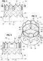
- FIGS. 1-3show various views of a prosthetic heart valve 10, according to one embodiment.
- the illustrated valveis adapted to be implanted in the native aortic annulus, although in other embodiments it can be adapted to be implanted in the other native annuluses of the heart.
- the valve 10can have four main components: a stent, or frame, 12, a valvular structure 14, and a laminate sealing member 16.
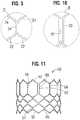
- the valvular structure 14can comprise three leaflets 40, collectively forming a leaflet structure, which can be arranged to collapse in a tricuspid arrangement, as best shown in FIG. 2 .
- the lower edge of leaflet structure 14desirably has an undulating, curved scalloped shape (suture line 108 shown in FIG. 19F tracks the scalloped shape of the leaflet structure).
- the scalloped geometryalso reduces the amount of tissue material used to form leaflet structure, thereby allowing a smaller, more even crimped profile at the inflow end of the valve.
- the leaflets 40can be formed of pericardial tissue (e.g., bovine pericardial tissue), biocompatible synthetic materials, or various other suitable natural or synthetic materials as known in the art and described in U.S. Pat. No. 6,730,118 .
- the bare frame 12is shown in FIG. 4 .
- the frame 12can be formed with a plurality of circumferentially spaced slots, or commissure windows, 20 (three in the illustrated embodiment) that are adapted to mount the commissures of the valvular structure 14 to the frame, as described in greater detail below.
- the frame 12can be made of any of various suitable plastically-expandable materials (e.g., stainless steel, etc.) or self-expanding materials (e.g., Nitinol) as known in the art.
- the frame 12(and thus the valve 10) can be crimped to a radially compressed state on a delivery catheter and then expanded inside a patient by an inflatable balloon or equivalent expansion mechanism.
- the frame 12When constructed of a self-expandable material, the frame 12 (and thus the valve 10) can be crimped to a radially compressed state and restrained in the compressed state by insertion into a sheath or equivalent mechanism of a delivery catheter. Once inside the body, the valve can be advanced from the delivery sheath, which allows the valve to expand to its functional size.
- Suitable plastically-expandable materials that can be used to form the frame 12include, without limitation, stainless steel, a nickel based alloy (e.g., a cobalt-chromium or a nickelcobalt-chromium alloy), polymers, or combinations thereof.
- frame 12is made of a nickel-cobalt-chromium-molybdenum alloy, such as MP35N TM (tradename of SPS Technologies), which is equivalent to UNS R30035 (covered by ASTM F562-02).
- MP35N TM /UNS R30035comprises 35% nickel, 35% cobalt, 20% chromium, and 10% molybdenum, by weight.
- MP35Nto form frame 12 provides superior structural results over stainless steel.
- MP35Nwhen MP35N is used as the frame material, less material is needed to achieve the same or better performance in radial and crush force resistance, fatigue resistances, and corrosion resistance.
- the crimped profile of the framecan be reduced, thereby providing a lower profile valve assembly for percutaneous delivery to the treatment location in the body.
- the frame 12 in the illustrated embodimentcomprises a first, lower row I of angled struts 22 arranged end-to-end and extending circumferentially at the inflow end 13 of the frame; a second row II of circumferentially extending, angled struts 24; a third row III of circumferentially extending, angled struts 26; a fourth row IV of circumferentially extending, angled struts 28; and a fifth row V of circumferentially extending, angled struts 32 at the outflow end 15 of the frame.
- a plurality of substantially straight axially extending struts 34can be used to interconnect the struts 22 of the first row I with the struts 24 of the second row II.
- the fifth row V of angled struts 32are connected to the fourth row IV of angled struts 28 by a plurality of axially extending window frame portions 30 (which define the commissure windows 20) and a plurality of axially extending struts 31.
- Each axial strut 31 and each frame portion 30extends from a location defined by the convergence of the lower ends of two angled struts 32 to another location defined by the convergence of the upper ends of two angled struts 28.
- FIGS. 6, 7, 8 , 9 and 10are enlarged views of the portions of the frame 12 identified by letters A, B, C, D and E, respectively, in FIG. 4 .
- Each commissure window frame portion 30mounts a respective commissure of the leaflet structure 14.
- each frame portion 30is secured at its upper and lower ends to the adjacent rows of struts to provide a robust configuration that enhances fatigue resistance under cyclic loading of the valve compared to known cantilevered struts for supporting the commissures of the leaflet structure.
- This configurationenables a reduction in the frame wall thickness to achieve a smaller crimped diameter of the valve.
- the thickness T of the frame 12 ( FIG. 4 ) measured between the inner diameter and outer diameteris about 0.48 mm or less.
- the struts and frame portions of the framecollectively define a plurality of open cells of the frame.
- struts 22, struts 24, and struts 34define a lower row of cells defining openings 36.
- the second, third, and fourth rows of struts 24, 26, and 28define two intermediate rows of cells defining openings 38.
- the fourth and fifth rows of struts 28 and 32, along with frame portions 30 and struts 31,define an upper row of cells defining openings 40.
- the openings 40are relatively large and are sized to allow portions of the leaflet structure 14 to protrude, or bulge, into and/or through the openings 40 when the frame 12 is crimped in order to minimize the crimping profile.
- the lower end of the strut 31is connected to two struts 28 at a node or junction 44, and the upper end of the strut 31 is connected to two struts 32 at a node or junction 46.
- the strut 31can have a thickness S1 that is less than the thicknesses S2 of the junctions 44, 46.
- the junctions 44, 46, along with junctions 64,can prevent full closure of openings 40.
- the geometry of the struts 31, and junctions 44, 46 and 64can assist in creating enough space in openings 40 in the crimped state to allow portions of the leaflets to protrude (i.e., bulge) outwardly through openings. This allows the valve to be crimped to a relatively smaller diameter than if all of the leaflet material is constrained within the crimped frame.
- the frame 12is configured to prevent or at least minimize possible over-expansion of the valve at a predetermined balloon pressure, especially at the outflow end portion of the frame, which supports the leaflet structure 14.
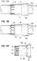
- the frameis configured to have relatively larger angles 42 a , 42 b, 42 c, 42 d, 42 e between struts. The larger the angle, the greater the force required to open (expand) the frame. This phenomenon is schematically illustrated in FIGS. 15A and 15B.
- FIG. 15Ashows a strut 32 when the frame 12 is in its compressed state (e.g., mounted on a balloon).
- the vertical distance d 1 between the ends of the strutsis greatest when the frame is compressed, providing a relatively large moment between forces F 1 and F 2 acting on the ends of the strut in opposite directions upon application of an opening force from inflation of the balloon (or expansion of another expansion device).
- the vertical distance between the ends of the strutdecreases to a distance d 2 , as depicted in FIG. 15B .
- the moment between forces F 1 and F 2As the vertical distance decreases, so does the moment between forces F 1 and F 2 .
- a relatively greater expansion forceis required as the vertical distance and the moment between the ends of the strut decreases.
- strain hardeningat the ends of the strut increases as the frame expands, which increases the expansion force required to induce further plastic deformation at the ends of the strut.
- the angles between the struts of the framecan be selected to limit radial expansion of the frame at a given opening pressure (e.g., inflation pressure of the balloon). In particular embodiments, these angles are at least 110 degrees or greater when the frame is expanded to its functional size, and even more particularly these angles are at least 120 degrees or greater when the frame is expanded to its functional size.
- the inflow and outflow ends of a framegenerally tend to over-expand more so than the middle portion of the frame due to the "dog boning" effect of the balloon used to expand the valve.
- the leaflet structuredesirably is secured to the frame 12 below the upper row of struts 32, as best shown in FIG. 1 .
- the leaflet structureis positioned at a level below where over-expansion is likely to occur, thereby protecting the leaflet structure from over-expansion.
- the leafletscan protrude outwardly beyond the outflow end of the frame when the valve is crimped if the leaflets are mounted too close to the distal end of the frame.
- the delivery catheter on which the crimped valve is mountedincludes a pushing mechanism or stop member that pushes against or abuts the outflow end of the valve (for example, to maintain the position of the crimped valve on the delivery catheter), the pushing member or stop member can damage the exposed leaflets that extend beyond the outflow end 15 of the frame 12.
- Another benefit of mounting the leaflets at a location spaced from the outflow end 15 of the frame 12is that when the valve is crimped on a delivery catheter, the leaflets 40 do not protrude beyond the outflow end 15 of the frame 12 in the axial direction.
- the delivery catheterincludes a pushing mechanism or stop member that pushes against or abuts the outflow end of the valve, the pushing mechanism or stop member can contact the end of the frame 12, and not leaflets 40, so as to avoid damage to the leaflets.
- the openings 36 of the lowermost row of openings in the frame 12are relatively larger than the openings 38 of the two intermediate rows of openings. This allows the frame, when crimped, to assume an overall tapered shape that tapers from a maximum diameter D 1 at the outflow end of the valve to a minimum diameter D 2 at the inflow end of the valve, as shown in FIG. 16 and further described in U.S. Patent Publication No. 2012/0123529 .
- the frame 12has a reduced diameter region extending along a portion of the frame adjacent the inflow end of the frame, indicated by reference number 174, which generally corresponds to the region of the frame covered by the cuff 21 of the laminated sealing member 16, further described below.
- the diameter of region 174is reduced compared to the diameter of the upper portion of the frame such that the cuff 21 need not increase the overall crimp profile of the valve.
- the framecan expand to the cylindrical shape shown in FIG. 4 .
- the frame of a 26-mm valvewhen crimped, had a diameter D 1 of 14 French at the outflow end of the valve and a diameter D 2 of 12 French at the inflow end of the valve.
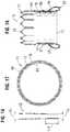
- FIGS. 11 and 12show an alternative frame 50 that can be incorporated in the valve 10.
- the frame 50comprises multiple rows of circumferentially extending, angled struts 52 that are connected to each other at nodes, or connecting portions, 54 and 56.
- the uppermost row of struts 52are connected to an adjacent row of struts by a plurality of axially extending struts 58 and commissure window frame portions 60.
- Each commissure frame portion 60defines a slot or commissure window 62 for mounting a respective commissure of the valvular structure, as described in U.S. Patent Publication No. 2012/0123529 .
- the thickness T of the frame 50is about 0.45 mm or less.
- FIGS. 13 and 14are enlarged views of the portions of the frame 50 identified by letters A and B, respectively, in FIG. 12 .
- the laminate sealing member 16can include a main portion 17 extending from the proximal end of the fourth row IV of angled struts 28 (i.e., from about the height of the commissure windows 20), and an end portion 19 extending from the inflow end 13 of the frame 12, as shown in FIGS. 1-3 .
- the end portion 19can be folded back on itself and secured to the main portion 17 to form a cuff 21 adjacent the inflow end 13 of the frame 12, as shown in FIGS. 1-3 , and 18 .
- the end portion 19can include a plurality of circumferentially spaced apart extension portions or projections 23 that can be secured to the main portion 17 by, for example, heat bonding, adhesive, and/or suturing, as further described below.
- the laminate sealing member 16can seal against the tissue of the native valve annulus, helping to reduce paravalvular leakage past the prosthetic valve 10.
- the cuff 21can billow open such that it defines a pocket in the laminate sealing member 16 extending circumferentially around the inflow end 13 of the frame 12 when the prosthetic valve is implanted in a native valve annulus.
- the end portion 19can lie relatively flush against the main portion 17, as desired.
- the laminate sealing member 16can comprise inner and outer encapsulating layers 84, 86, respectively (also referred to as "inner and outer layers"), as shown in FIGS. 17 and 18 .
- the encapsulating layers 84, 86comprise a non-fabric polymer layer or film.
- the laminate sealing member 16can also include a reinforcing layer, such as a fabric or textile layer 18 situated adjacent the frame 12 between the encapsulating layers 84, 86.
- the encapsulating layers 84, 86can be fused, bonded, or otherwise secured to each other through the openings in the frame 12, which effectively encapsulates corresponding portions of the frame 12 and the fabric layer 18 to secure these components in their assembled state shown in FIGS. 1-3 .
- the inner and outer encapsulating layers 84, 86can be coextensive along the axial length of the main portion 17 of the laminate sealing member 16.
- the encapsulating layers 84, 86can both extend distally from about the level of the commissure windows 20 to the inflow end of the frame to completely or substantially encapsulate the corresponding portion of the frame 12 and the fabric layer 18, as shown in FIG. 18 .
- the inner layer 84can terminate at or near the inflow end 13 of the frame 12, while the outer layer 86 can extend beyond the inflow end to form the end portion 19 of the laminate sealing member 16 and, hence, the cuff 21.
- the inner layer 84forms an inner skirt of the sealing member and the outer layer 86 forms an outer skirt of the sealing member.
- the inner and/or outer layers 84, 86can extend along any proportion of the main portion 17 or the end portion 19 of the laminate sealing member 16, as desired.
- the inner and outer layers 84, 86can be coextensive along both the main portion 17 and the end portion 19 of the laminate sealing member 16.
- the outer layer 86can terminate at the inflow end 13 of the frame 12, while the inner layer 84 can continue beyond the inflow end 13 to form the cuff 21.
- the layers 84, 86can be such that they only encapsulate selected portions of the frame 12 and the fabric layer 18.
- the inner and outer layers 84, 86are tubular or cylindrical in shape, the inner and outer layers 84, 86 need not extend along the respective inner and outer surfaces of the frame 12 in the circumferential direction through 360 degrees.
- the inner and outer layers 84, 86can have a cross-sectional profile (in a plane perpendicular to the axis of the lumen of the valve) that is not a complete circle.
- the laminate sealing member 16can comprise a reinforcing layer, such as the fabric layer 18.
- the fabric layer 18can comprise, for example, any of various woven fabrics, such as gauze, polyethylene terephthalate (PET) fabric (e.g., Dacron), polyester fabric, polyamide fabric, or any of various non-woven fabrics, such as felt.
- PETpolyethylene terephthalate
- the thickness of the fabric layercan vary, but can be less than 6 mil, and desirably less than 4 mil, and even more desirably about 2 mil.
- fabric skirtshave been secured to frames using sutures.
- fabric layer 18desirably is secured to the frame 12 without sutures and instead is secured to the frame 12 with the inner and/or outer encapsulating layers 84, and 86 (see, e.g., FIGS. 17 and 18 ).
- the fabric layer 18 of the prosthetic valvecan serve several functions.
- the fabric layer 18primarily functions to strengthen the laminate sealing member 16 to resist tearing. In this manner, the leaflet structure 14 can be anchored to the frame 12 by sutures without tearing the laminate sealing member 16.
- the fabric layer 18, in cooperation with the encapsulating layers 84, 86,can help decrease (or prevent) paravalvular leakage past the prosthetic valve when in the expanded configuration.
- the reinforcing layercan comprise one or more layers or films formed from any of various semi-crystalline polymeric materials or thermoplastics having aligned or partially aligned (e.g., parallel) molecular chains. Such materials can exhibit anisotropic mechanical properties, such as increased mechanical strength along the longitudinal direction of the molecular chains.
- Suitable semi-crystalline polymeric materialscan include, for example, PTFE, PET, polypropylene, polyamide, polyetheretherketone (PEEK), etc., layers or films of which can be situated between and encapsulated by the encapsulating layers to reinforce the laminate sealing member 16.
- the encapsulating layers 84, 86can be made of any suitable biocompatible material.
- the encapsulating layers 84, 86can be formed using an electrospinning process.
- the encapsulating layers 84, 86can be formed using any other suitable method including, for example, dip coating, spray coating, or melt-spinning.
- the biocompatible materialmay be a non-absorbable polymeric material (i.e., a material that does not dissolve once implanted in the body).
- ePTFEexpanded polytetrafluoroethylene
- UHMWPEultrahigh molecular weight polyethylene
- FEPfluoroethylpolypropylene
- PFApolypropylfluorinated amines
- the encapsulating layers 84, 86are formed from respective tubes made of a suitable polymeric material (e.g., ePTFE tubes or UHMWPE tubes) that are bonded to each other when subjected to heat treatment, as described in detail below.
- a suitable polymeric materiale.g., ePTFE tubes or UHMWPE tubes
- Microporous expanded polytetrafluoroethylene (ePTFE) tubescan be made by a number of well-known methods. Expanded PTFE is frequently produced by admixing particulate dry polytetrafluoroethylene resin with a liquid lubricant to form a viscous slurry. The mixture can be poured into a mold, typically a cylindrical mold, and compressed to form a cylindrical billet. The billet can then be ram extruded through an extrusion die into either tubular or sheet structures, termed extrudates in the art.
- the extrudatescomprise an extruded PTFE-lubricant mixture called "wet PTFE.”
- Wet PTFEhas a microstructure of coalesced, coherent PTFE resin particles in a highly crystalline state.
- the wet PTFEcan be heated to a temperature below the flash point of the lubricant to volatilize a major fraction of the lubricant from the PTFE extrudate.
- the resulting PTFE extrudate without a major fraction of lubricantis known in the art as dried PTFE.
- the dried PTFEcan then be either uniaxially, biaxially, or radially expanded using appropriate mechanical apparatus known in the art.
- Expansionis typically carried out at an elevated temperature, e.g., above room temperature but below 327 degrees C., the crystalline melt point of PTFE.
- Uniaxial, biaxial, or radial expansion of the dried PTFEcauses the coalesced, coherent PTFE resin to form fibrils emanating from nodes (regions of coalesced PTFE), with the fibrils oriented parallel to the axis of expansion.
- the dried PTFEis referred to as expanded PTFE ("ePTFE”) or microporous PTFE.
- UHMWPEis made up of very long chains of polyethylene, with molecular weight numbering in the millions, usually between 2 and 6 million. It is highly resistant to corrosive chemicals, has extremely low moisture absorption and a very low coefficient of friction. It is self-lubricating and highly resistant to abrasion. UHMWPE is processed using compression molding, ram extrusion, gel spinning, and sintering. UHMWPE is available commercially as a powder, in sheets or rods, and as fibers.
- an inner layer 84comprising a flat piece of ePTFE material or an ePTFE tube can be placed or wrapped on a mandrel 100.
- a frame 12can be placed over the inner layer 84 such that the inner layer 84 extends from approximately the commissure windows 20 to the inflow end 13 of the frame 12, although it will be appreciated that other configurations are possible.
- the fabric layer 18can be placed over the frame 12. The fabric layer 18 can be in the form of a sheet of fabric material that is tightly wrapped around the outer surface of the frame 12.
- the fabric layer 18may also be situated inside the frame 12 (e.g., placed on the inner layer 84 before placement of the frame 12 on the inner layer 84).
- the fabric layer 18may have an axial length that is shorter than the inner and outer layers 84, 86 to facilitate bonding of the inner and outer layers 84, 86 at their respective ends to encapsulate the frame 12 and fabric layer 18 therebetween.
- the outer layer 86comprising a flat piece of ePTFE material or an ePTFE tube can be placed or wrapped over the fabric layer 18.
- the outer layer 86can have a proximal portion 87 and a distal portion 89, wherein the distal portion 89 can have a diameter that is greater than the diameter of the proximal portion 87.
- the extension portions 23 of the outer layer 86can be formed on the distal portion 89 (e.g., by laser cutting) before or after placement of the outer layer 86 on the mandrel 100, as desired.
- layers of PTFE tape 92can then be wrapped around one or both ends of the outer layer 86 to help secure the position of the outer layer 86 to the underlying layers of the assembly and to the mandrel 100 during subsequent processing.
- Electrospinninguses an electrical charge to draw very fine (typically on the micrometer or nanometer scale) fibers from a liquid.
- the assembly shown in FIG. 19Ecan now undergo an encapsulation process whereby the assembly is subjected to heat and/or pressure to cause the inner and outer layers 84, 86 to bond to each other through the openings in the frame 12 proximally and distally of the fabric layer 18 (see FIG. 18 ) to encapsulate the frame 12 and the fabric layer 18 therebetween.
- the layers 84, 86can bond to each other through the fabric layer 18.
- the entire outer surface of the assembly on the mandrel 100can be tightly wrapped with a suitable material (e.g., PTFE tape) to apply pressure to the various layers of the assembly such that the layers 84, 86 form a monolithic laminate sealing member 16.
- a suitable materiale.g., PTFE tape
- the entire assembly, including the mandrel 100,can be transferred to an oven where the inner and outer layers 84, 86 are sintered by being heated to a predetermined temperature.
- the inner and outer layers 84, 86are sintered by being heated to a temperature above 327 degrees C, the crystalline melt point of PTFE.
- bonding between the inner and outer layers 84, 86can be facilitated by the use of one or more adhesives, such as polyurethane.
- the ePTFEis restrained against uniaxial, biaxial, or radial contraction.
- Sinteringcan cause at least a portion of the crystalline PTFE to change from a crystalline state to an amorphous state.
- the conversion from a highly crystalline structure to one having an increased amorphous contentcan lock the node and fibril microstructure, as well as its orientation relative to the axis of expansion, and provide a dimensionally stable tubular or sheet material upon cooling.
- the assemblyis removed from the oven and allowed to cool.
- the material wrapped around the assembly, as well as tape layers 92,can now be removed. Any portions of the inner and outer layers 84, 86 that extend beyond the desired dimensions of the laminate sealing member 16 can be trimmed. If desired, selected portions of the inner and outer layers 84, 86 can be removed to facilitate crimping of the valve for delivery into a patient. Any of various suitable techniques and mechanisms can be used to selectively remove portions of layers 84, 86, such as laser cutting. For example, portions of the inner and outer layers 84, 86 that cover selected openings in the frame 12 can be cut or otherwise removed to minimize the amount of material in the valve, which can facilitate crimping of the valve to a relatively small diameter.
- the end portion 19 of the laminate sealing member 16can be folded over to form the cuff 21, and the extension portions 23 can be secured to the main portion 17 of the laminate sealing member 16.
- the extension portions 23can be attached to the main portion 17 by heat bonding (e.g., in combination with an optional additional polymer such as polyurethane to promote bonding between the ePTFE layers, with process temperatures adjusted as necessary).
- the extension portions 23can be attached to the main portion by suturing.
- the end portion 19 and/or the extension portions 23can include a reinforcing fabric layer to facilitate suturing of the end portion 19 to the main portion 17.
- the cuff 21can be secured to the main portion via heat bonding, an adhesive, and/or suturing.
- the cuff 21is secured to the main body 17 only along the uppermost edges of the extension portions 23 and the U-shaped upper edge portions 25 defining the gaps are not secured to the frame.
- the cuff 21can form a pocket having openings defined by the U-shaped edges 25.
- the fabric layer 18can be pre-formed in a tubular or cylindrical configuration.
- the fabric layer 18can be positioned on the frame 12 by first partially crimping the frame 12 to a diameter smaller than the diameter of the fabric layer 18.
- the fabric layer 18can then be placed over the partially crimped frame, and the frame can be expanded back to its functional size.
- the fabric layer 18desirably is sized such that the expanded frame 12 applies at least some outward radial pressure against the fabric layer 18 to assist in retaining the fabric layer 18 on the frame 12.
- the frame and fabric layer assemblycan then be placed onto inner layer 84 (already on the mandrel), and encapsulated following the process described above.
- the fabric layer 18can be placed on the inside of the frame 12.
- the fabric layer 18can be in the form of a sheet of material that is wrapped around inner layer 84 prior to placing the frame 12 on the mandrel 100.
- the fabric layer 18can have a tubular configuration and can be positioned onto inner layer 84 prior to placing the frame 12 on the mandrel 100.
- the frame 12can be removed from the mandrel 100 and the leaflet structure 14 can be attached to the fabric layer 18 and/or the frame 12 using sutures or other suitable techniques or mechanisms.
- the leaflets 40are secured to one another at their adjacent sides to form commissures 48. Each commissure 48 can be secured to a corresponding commissure window 20 of the frame 12, as described in U.S. Patent Publication No. 2012/0123529 .
- the lower, or inflow, end portion of the leaflets 40can be sutured to the fabric layer 18 of the laminate sealing member 16 along a suture line 108 that tracks the curvature of the scalloped lower edge of the leaflet structure, as shown in FIG. 19F .
- the fabric layer 18can provide the strength required to retain the sutures without tearing the laminate sealing member 16. Any suitable suture, such as an Ethibond suture, can be used to secure the leaflets 40 to the fabric layer 18 of the laminate sealing member 16 along suture line 108.
- the lower edges of the leaflets 40can be secured to the fabric layer 18 via a thin PET reinforcing strip (not shown), as disclosed in U.S. Pat. No. 7,993,394 .
- the reinforcing stripcan be sutured to the lower edges of the leaflets.
- the reinforcing strip and the lower edges of the leafletscan then be sutured to the laminate sealing member 16 along suture line 108.
- the reinforcing stripdesirably is secured to the inner surfaces of the leaflets 40 such that the lower edges of the leaflets become sandwiched between the reinforcing strip and the laminate sealing member 16 when the leaflets and the reinforcing strip are secured to the laminate sealing member.
- the reinforcing stripenables a secure suturing and protects the pericardial tissue of the leaflet structure from tears.
- the conventional method for securing a fabric skirt to a frameinvolves manually suturing the fabric skirt to the frame.
- the illustrated embodimentrelies on the inner and outer layers 84, 86 to secure the fabric layer 18 in place relative to the frame.
- this technique for securing the fabric layer 18 to the framecan significantly reduce the amount of labor required to assemble a valve.
- the use of layers 84, 86provides other advantages as well.
- the outer layer 86when formed from ePTFE or UHMWPE, has a porous microstructure that facilitates tissue in-growth from surrounding tissue after the valve is implanted.
- the laminate sealing member 16can exhibit lower blood permeability than conventional fabric skirts, especially in the period immediately following implantation, which can help to reduce paravalvular leakage.
- the inner and outer layers 84, 86can protect the leaflets 40 during crimping and facilitate even and predictable crimping of the valve.
- a prosthetic valveWhen a prosthetic valve is placed in a crimping apparatus to radially compress the valve to a smaller diameter for insertion into a patient, the leaflets of the valve are pressed against the inner surface of the metal frame and portions of the tissue can protrude into the open cells of the frame between the struts and can be pinched due to the scissor-like motion of the struts of the frame. If the valve is severely crimped to achieve a small crimping size, this scissor-like motion can result in cuts and rupture of the tissue leaflets.
- the valve 10can be crimped onto the balloon of a balloon catheter in an even and predictable manner that forms a very ordered structure of balloon-leaflets-frame (from inward to outward). Additionally, inner layer 84 can prevent direct contact between the leaflets 40 and the frame 12 during working cycles of the valve (i.e., as the valve leaflets open and close in response to blood pressure) to protect the leaflets against damage caused by contact with the frame.
- the fabric layer 18can be any of various woven or non-woven fabrics, such as a gauze, PET cloth, or felt. PET or other fabrics are substantially non-elastic (i.e., substantially non-stretchable and non-compressible). As such, in known prosthetic valves, the skirt can wrinkle after expansion from the crimped diameter. In the illustrated embodiment, the fabric layer 18 can be tightly compressed against the frame by layers 84, 86 such that when the valve is expanded to its functional size from the crimped state, the fabric layer 18 can recover to its original, smooth surfaces with little or no wrinkling.
- the encapsulation processis described above in the context of securing a fabric layer to the frame of an expandable transcatheter heart valve within a laminate sealing member.
- the fabric layertypically is more durable than the ePTFE layers and, therefore, the fabric layer reinforces the ePTFE layers where they undergo stresses from cyclic loading of the valve.
- the valvecan be formed without the fabric layer to permit crimping of the valve to a smaller delivery diameter.
- the ePTFE layers 84, 86, and the cuff 21can serve as the primary sealing mechanism that prevents paravalvular leakage around or through the frame of the valve.
- the fabric layer 18can be used to reinforce only selected portions of the layers 84, 86, such as those portions of layers 84, 86 subject to greatest loading, while the remaining portions of layers 84, 86 do not contain a fabric layer or fabric layer.
- the encapsulation processcan be utilized to secure a fabric or woven or non-woven textile element to other components of a prosthetic valve.
- surgical valvesvalves which are typically implanted via open-heart surgery
- Known surgical valvestypically have a sewing ring and one or more stent components, each of which are covered with a cloth member.
- the cloth membertypically is wrapped around the valve component and the longitudinal edges of the cloth member are manually stitched to each other to secure the cloth member around the valve component.
- the time and labor required to secure such cloth members to the components of the valvecan be significantly reduced by employing an encapsulation technique as described herein.
- FIG. 20schematically illustrates a representative method of encapsulating a frame of a prosthetic valve to form a laminate sealing member.
- an inner layercomprising, for example, ePTFE, can be positioned over a mandrel.
- a framecan be positioned on the mandrel over the inner layer.
- an outer layercomprising, for example, ePTFE, can be positioned on the mandrel over the frame.
- the inner and outer layerscan be fused to one another to create a laminate sealing member encapsulating at least a portion of the frame therebetween.
- an end portion of the laminate sealing membercan be folded up and secured to a main portion of the laminate sealing member to form a cuff.
- the laminate sealing membercan optionally include a fabric or textile layer located between the inner and outer layers adjacent the inside or outside of the frame, as described above.
- FIGS. 21-24illustrate another embodiment of a sealing member 300 including a main portion 302, an intermediate portion 304, and an end portion 306.
- the main portion 302can have a diameter D M corresponding substantially to an inner diameter of an expanded frame 308.
- the end portion 306can have a diameter D E that is equal to or greater than an outer diameter of the expanded frame 308, and the intermediate portion 304 can have a diameter that increases or flares in a longitudinal direction of the sealing member from the diameter D M of the main portion 302 to the diameter D E of the end portion 306.
- the intermediate portioncan have a frustoconical shape.
- the end portion 306 of the sealing member 300can be folded (e.g., along the interface 316 between the intermediate portion and the end portion and the interface 318 between the main portion and the intermediate portion) and secured to the main portion 302, as shown in FIGS. 21 and 22 .
- the sealing membercan be secured to the inside of the frame 308 such that the main portion 302 is adjacent an inner surface of the frame and the end portion 306 extends distally from an inflow end 310 of the frame 308.
- the end portion 306can then be folded upwardly and around the inflow end 310 of the frame and attached to the main portion 302 (through the frame) and/or to the exterior of the frame 308 to form a cuff 312 adjacent the inflow end 310 of the frame.
- the sealing member 300can combine the functions of conventionally separate inner and outer skirts into a single unitary sealing member. This can reduce the amount of material around the inflow end of the valve, thereby reducing the crimped profile of the valve, along with flow disturbances or obstructions created by the sealing member when inserted into a native heart valve. Use of the sealing member described herein can also reduce the time and labor required to assemble a valve over known valve skirts.
- the end portion 306can include tabs or projections 314, which can be secured to the main portion 302 of the sealing member and/or to the exterior of the frame members by, for example, stitching, adhesive, heat bonding, etc.
- the projections 314can aid in folding the end portion 306 to form the cuff 312, thereby reducing the need for complex shaping of the sealing member.
- the main portion 302can also include tabs or projections.
- the sealing member 300may be made from any of various woven fabrics such as PET, polybutylene terephthalate (PBT), UHMWPE, polypropylene, natural fibers such as silk, etc.
- the fabricmay be woven or braided into the final shape of the sealing member 300.
- the sealing member 300may be formed from a tubular piece of material, such as by application of heat or by shape setting.
- the projections 314can be created by, for example, cutting sections of material from the end portion 306. Additionally, it should be understood that the shape of the sealing member 300 can be applicable to any of the sealing members described herein.
- the properties of the fabricmay be varied along the length of the sealing member.
- yarns in the fabric of the main portion 302may be set at an angle (e.g., 45 degrees) such that the fabric of the main portion can more easily elongate and/or foreshorten during crimping and expansion of the frame.
- a fabric sealing member(e.g., the sealing member 300) can be laminated with or encapsulated between one or more layers or films of ePTFE (e.g., 0.00508 mm to 0.0254 mm (0.00020 inch to 0.001 inch) Aeos ® ePTFE material available from Zeus Industrial Products, Inc.).
- ePTFEe.g., 0.00508 mm to 0.0254 mm (0.00020 inch to 0.001 inch) Aeos ® ePTFE material available from Zeus Industrial Products, Inc.
- one or more layers of ePTFEcan be applied to at least one surface of the sealing member to reduce the permeability of the sealing member. This can reduce the amount of blood leakage through the sealing member, especially in the time period immediately following implantation.
- the smooth surface of the one or more ePTFE layerscan also improve the durability of the tissue leaflets contacting the ePTFE layers, and can reduce or prevent the exposure of broken yarns or filaments in the underlying fabric, improving yields during manufacturing of the heart valves.
- the number and thickness of the one or more ePTFE layers, along with other parameters including the internodal distance, porosity, etc., of the ePTFE,can be varied according to the particular properties desired.
- one or more layers of ePTFEare applied to both surfaces of a sealing member (e.g., sealing member 300) before it is assembled onto a frame.
- the singular forms “a,” “an,” and “the”include the plural forms unless the context clearly dictates otherwise. Additionally, the term “includes” means “comprises.” Further, the terms “coupled” and “associated” generally mean electrically, electromagnetically, and/or physically (e.g., mechanically or chemically) coupled or linked and does not exclude the presence of intermediate elements between the coupled or associated items absent specific contrary language.
- the terms “lower” and “upper”are used interchangeably with the terms “inflow” and “outflow”, respectively.
- the lower end of the valveis its inflow end and the upper end of the valve is its outflow end.
- proximalrefers to a position, direction, or portion of a device that is closer to the user and further away from the implantation site.
- distalrefers to a position, direction, or portion of a device that is further away from the user and closer to the implantation site.
- proximal motion of a deviceis motion of the device toward the user
- distal motion of the deviceis motion of the device away from the user.
- longitudinal and axialrefer to an axis extending in the proximal and distal directions, unless otherwise expressly defined.
Landscapes
- Health & Medical Sciences (AREA)
- Engineering & Computer Science (AREA)
- Cardiology (AREA)
- Biomedical Technology (AREA)
- Life Sciences & Earth Sciences (AREA)
- Transplantation (AREA)
- Heart & Thoracic Surgery (AREA)
- Vascular Medicine (AREA)
- Oral & Maxillofacial Surgery (AREA)
- Animal Behavior & Ethology (AREA)
- General Health & Medical Sciences (AREA)
- Public Health (AREA)
- Veterinary Medicine (AREA)
- Mechanical Engineering (AREA)
- Manufacturing & Machinery (AREA)
- Prostheses (AREA)
Description
- The present disclosure relates to implantable prosthetic valves and, more particularly, to laminated sealing members for prosthetic valves and methods of making the same.
- Known prosthetic valves include a frame with a valvular structure mounted therein, an inner skirt or sealing member secured to the inside of the frame, and an outer skirt or sealing member secured to the exterior of the frame. The inner and outer skirts frequently must be secured to the frame by suturing or stitching the fabric of the respective skirts to the frame. Such suturing must often be done by hand, increasing the cost and time required to produce a prosthetic valve. Accordingly, improvements to skirts for prosthetic valves are desirable.
US 2013/0338765 A1 discloses a prosthetic heart valve which is provided with a cuff having features which promote sealing with the native tissues even where the native tissues are irregular. The cuff may include a portion adapted to bear on the LVOT when the valve is implanted in a native aortic valve. The valve may include elements for biasing the cuff outwardly with respect to the stent body when the stent body is in an expanded condition. The cuff may have the portions of different thickness distributed around the circumference of the valve in a pattern matching the shape of the opening defined by the native tissue. All or part of the cuff may be movable relative to the stent during implantation.US 2012/296418 A1 discloses implantable prosthetic devices, and in particular, implantable prosthetic valves, and methods for making such devices. In one aspect, a prosthetic device includes encapsulating layers that extend over a fabric layer and secure the fabric layer to another component of the device. In particular embodiments, the prosthetic device comprises a prosthetic heart valve, and can be configured to be implanted in any of the native heart valves. In addition, the prosthetic heart valve can be, for example, a transcatheter heart valve, a surgical heart valve, or a minimally-invasive heart valve.- Certain embodiments of the disclosure concern laminated sealing members for prosthetic heart valves and methods of making the same. In one representative embodiment, an implantable prosthetic valve that is defined in claim 1 and that is radially collapsible to a collapsed configuration and radially expandable to an expanded configuration comprises an annular frame having an inflow end and an outflow end, a leaflet structure positioned within the frame and secured thereto, and a laminate sealing member comprising an encapsulating material. The laminate sealing member has a main portion that encapsulates at least a portion of the frame and an end portion extending from the inflow end of the frame, wherein the laminate sealing member comprises a first tubular layer positioned on the inside of the frame and a second tubular layer positioned on the outside of the frame, the first and second tubular layers being fused together to encapsulate corresponding portions of the frame, wherein the inner layer terminates near the inflow end of the frame, and the outer layer extends beyond the inflow end of the frame to form the end portion of the laminate sealing member and wherein the end portion of the laminate sealing member is folded to form a cuff adjacent the inflow end of the frame and secured to the main portion of the laminate sealing member.
- In another representative embodiment, a method of making a prosthetic heart valve comprises positioning a first layer about a mandrel, positioning a radially expandable frame over the first layer wherein the frame has an inflow end and an outflow end, and positioning a second layer over the radially expandable frame. The method further comprises fusing the first and second layers to form a monolithic laminate sealing member such that at least a portion of the frame is encapsulated within the laminate sealing member, wherein the first layer terminates near the inflow end of the frame, and the second layer extends beyond the inflow end of the frame to form an end portion of the laminate sealing member, and folding an end portion of the laminate sealing member and securing it to a main portion of the laminate sealing member to form a cuff adjacent an inflow end of the frame.
- In another representative embodiment, a transcatheter heart valve comprises a radially expandable frame having an inflow end, an outflow end, and a laminate sealing member comprising a non-fabric inner layer positioned inside of the frame, a non-fabric outer layer positioned outside of the frame, and a fabric layer positioned between the non-fabric inner layer and the non-fabric outer layer. The non-fabric inner and outer layers are fused to one another such that the fabric layer and at least a portion of the frame are encapsulated therebetween. The laminate sealing member further comprises a main portion adjacent the frame and an end portion extending from the inflow end of the frame, the end portion being folded to form a cuff adjacent the inflow end of the frame and secured to the main portion of the laminate sealing member.
- The foregoing and other objects, features, and advantages of the disclosure will become more apparent from the following detailed description, which proceeds with reference to the accompanying figures.
FIGS. 1-3 illustrate an exemplary embodiment of a prosthetic valve including a laminate sealing memberFIGS. 4-10 illustrate an exemplary frame of the heart valve ofFIG. 1 .FIGS. 11-15B illustrate another embodiment of a frame for use with a prosthetic heart valve.FIG. 16 illustrates a cross-sectional profile of the frame ofFIG. 4 , showing a general tapering from the outflow end to the inflow end.FIG. 17 is a cross-sectional view of the prosthetic heart valve ofFIG. 2 taken along line 17-17.FIG. 18 is a cross-sectional view of the prosthetic heart valve ofFIG. 1 taken along line 18-18.FIGS. 19A-19F illustrate a method of forming a laminate sealing member on the frame of a prosthetic heart valve, according to one embodiment.FIG. 20 is a flow chart of a method for forming a laminate sealing member on the frame of a prosthetic heart valve, according to one embodiment.FIG. 21 is a side elevation view illustrating another embodiment of a sealing member.FIG. 22 is a perspective view of the sealing member ofFIG. 21 folded to form a cuff.FIG. 23 is a perspective view illustrating the main portion of the sealing member ofFIG. 21 secured to a frame and the end portion extending distally from the frame.FIG. 24 is a perspective view illustrating the end portion of the sealing member ofFIG. 21 folded and secured to the frame to form a cuff.- The present disclosure concerns embodiments of implantable prosthetic devices and, in particular, implantable prosthetic valves, and methods for making such devices. In one aspect, a prosthetic device as defined in claim 1 includes encapsulating layers that extend over a fabric layer and secure the fabric layer to another component of the device. In particular embodiments, the prosthetic device comprises a prosthetic heart valve, and can be configured to be implanted in any of the native heart valves. The prosthetic heart valve can be, for example, a transcatheter heart valve, a surgical heart valve, or a minimally-invasive heart valve. The prosthetic valve also can comprise other types of valves implantable within other body lumens outside of the heart or heart valves that are implantable within the heart at locations other than the native valves, such as trans-atrial or trans-ventricle septum valves.
FIGS. 1-3 show various views of aprosthetic heart valve 10, according to one embodiment. The illustrated valve is adapted to be implanted in the native aortic annulus, although in other embodiments it can be adapted to be implanted in the other native annuluses of the heart. Thevalve 10 can have four main components: a stent, or frame, 12, avalvular structure 14, and alaminate sealing member 16.- The
valvular structure 14 can comprise threeleaflets 40, collectively forming a leaflet structure, which can be arranged to collapse in a tricuspid arrangement, as best shown inFIG. 2 . The lower edge ofleaflet structure 14 desirably has an undulating, curved scalloped shape (suture line 108 shown inFIG. 19F tracks the scalloped shape of the leaflet structure). By forming the leaflets with this scalloped geometry, stresses on the leaflets are reduced which, in turn, improves durability of the valve. Moreover, by virtue of the scalloped shape, folds and ripples at the belly of each leaflet (the central region of each leaflet), which can cause early calcification in those areas, can be eliminated or at least minimized. The scalloped geometry also reduces the amount of tissue material used to form leaflet structure, thereby allowing a smaller, more even crimped profile at the inflow end of the valve. Theleaflets 40 can be formed of pericardial tissue (e.g., bovine pericardial tissue), biocompatible synthetic materials, or various other suitable natural or synthetic materials as known in the art and described inU.S. Pat. No. 6,730,118 . - The
bare frame 12 is shown inFIG. 4 . Theframe 12 can be formed with a plurality of circumferentially spaced slots, or commissure windows, 20 (three in the illustrated embodiment) that are adapted to mount the commissures of thevalvular structure 14 to the frame, as described in greater detail below. Theframe 12 can be made of any of various suitable plastically-expandable materials (e.g., stainless steel, etc.) or self-expanding materials (e.g., Nitinol) as known in the art. When constructed of a plastically-expandable material, the frame 12 (and thus the valve 10) can be crimped to a radially compressed state on a delivery catheter and then expanded inside a patient by an inflatable balloon or equivalent expansion mechanism. When constructed of a self-expandable material, the frame 12 (and thus the valve 10) can be crimped to a radially compressed state and restrained in the compressed state by insertion into a sheath or equivalent mechanism of a delivery catheter. Once inside the body, the valve can be advanced from the delivery sheath, which allows the valve to expand to its functional size. - Suitable plastically-expandable materials that can be used to form the
frame 12 include, without limitation, stainless steel, a nickel based alloy (e.g., a cobalt-chromium or a nickelcobalt-chromium alloy), polymers, or combinations thereof. In particular embodiments,frame 12 is made of a nickel-cobalt-chromium-molybdenum alloy, such as MP35N™ (tradename of SPS Technologies), which is equivalent to UNS R30035 (covered by ASTM F562-02). MP35N™/UNS R30035 comprises 35% nickel, 35% cobalt, 20% chromium, and 10% molybdenum, by weight. It has been found that the use of MP35N to formframe 12 provides superior structural results over stainless steel. In particular, when MP35N is used as the frame material, less material is needed to achieve the same or better performance in radial and crush force resistance, fatigue resistances, and corrosion resistance. Moreover, since less material is required, the crimped profile of the frame can be reduced, thereby providing a lower profile valve assembly for percutaneous delivery to the treatment location in the body. - Referring to
FIGS. 4 and 5 , theframe 12 in the illustrated embodiment comprises a first, lower row I ofangled struts 22 arranged end-to-end and extending circumferentially at theinflow end 13 of the frame; a second row II of circumferentially extending, angled struts 24; a third row III of circumferentially extending, angled struts 26; a fourth row IV of circumferentially extending, angled struts 28; and a fifth row V of circumferentially extending, angled struts 32 at theoutflow end 15 of the frame. A plurality of substantially straight axially extendingstruts 34 can be used to interconnect thestruts 22 of the first row I with thestruts 24 of the second row II. The fifth row V ofangled struts 32 are connected to the fourth row IV ofangled struts 28 by a plurality of axially extending window frame portions 30 (which define the commissure windows 20) and a plurality of axially extendingstruts 31. Eachaxial strut 31 and eachframe portion 30 extends from a location defined by the convergence of the lower ends of twoangled struts 32 to another location defined by the convergence of the upper ends of twoangled struts 28.FIGS. 6, 7, 8 ,9 and 10 are enlarged views of the portions of theframe 12 identified by letters A, B, C, D and E, respectively, inFIG. 4 . - Each commissure
window frame portion 30 mounts a respective commissure of theleaflet structure 14. As can be seen eachframe portion 30 is secured at its upper and lower ends to the adjacent rows of struts to provide a robust configuration that enhances fatigue resistance under cyclic loading of the valve compared to known cantilevered struts for supporting the commissures of the leaflet structure. This configuration enables a reduction in the frame wall thickness to achieve a smaller crimped diameter of the valve. In particular embodiments, the thickness T of the frame 12 (FIG. 4 ) measured between the inner diameter and outer diameter is about 0.48 mm or less. - The struts and frame portions of the frame collectively define a plurality of open cells of the frame. At the inflow end of the
frame 12, struts 22, struts 24, and struts 34 define a lower row ofcells defining openings 36. The second, third, and fourth rows ofstruts cells defining openings 38. The fourth and fifth rows ofstruts frame portions 30 and struts 31, define an upper row ofcells defining openings 40. Theopenings 40 are relatively large and are sized to allow portions of theleaflet structure 14 to protrude, or bulge, into and/or through theopenings 40 when theframe 12 is crimped in order to minimize the crimping profile. - As best shown in
FIG. 7 , the lower end of thestrut 31 is connected to twostruts 28 at a node orjunction 44, and the upper end of thestrut 31 is connected to twostruts 32 at a node orjunction 46. Thestrut 31 can have a thickness S1 that is less than the thicknesses S2 of thejunctions junctions junctions 64, can prevent full closure ofopenings 40. The geometry of thestruts 31, andjunctions openings 40 in the crimped state to allow portions of the leaflets to protrude (i.e., bulge) outwardly through openings. This allows the valve to be crimped to a relatively smaller diameter than if all of the leaflet material is constrained within the crimped frame. - The
frame 12 is configured to prevent or at least minimize possible over-expansion of the valve at a predetermined balloon pressure, especially at the outflow end portion of the frame, which supports theleaflet structure 14. In one aspect, the frame is configured to have relativelylarger angles FIGS. 15A and 15B. FIG. 15A shows astrut 32 when theframe 12 is in its compressed state (e.g., mounted on a balloon). The vertical distance d1 between the ends of the struts is greatest when the frame is compressed, providing a relatively large moment between forces F1 and F2 acting on the ends of the strut in opposite directions upon application of an opening force from inflation of the balloon (or expansion of another expansion device). When the frame expands radially, the vertical distance between the ends of the strut decreases to a distance d2, as depicted inFIG. 15B . As the vertical distance decreases, so does the moment between forces F1 and F2. Hence, it can be seen that a relatively greater expansion force is required as the vertical distance and the moment between the ends of the strut decreases. Moreover, strain hardening (stiffening) at the ends of the strut increases as the frame expands, which increases the expansion force required to induce further plastic deformation at the ends of the strut. As such, the angles between the struts of the frame can be selected to limit radial expansion of the frame at a given opening pressure (e.g., inflation pressure of the balloon). In particular embodiments, these angles are at least 110 degrees or greater when the frame is expanded to its functional size, and even more particularly these angles are at least 120 degrees or greater when the frame is expanded to its functional size. - In addition, the inflow and outflow ends of a frame generally tend to over-expand more so than the middle portion of the frame due to the "dog boning" effect of the balloon used to expand the valve. To protect against over-expansion of the
leaflet structure 14, the leaflet structure desirably is secured to theframe 12 below the upper row ofstruts 32, as best shown inFIG. 1 . Thus, in the event that the outflow end of the frame is over-expanded, the leaflet structure is positioned at a level below where over-expansion is likely to occur, thereby protecting the leaflet structure from over-expansion. - In a known valve construction, the leaflets can protrude outwardly beyond the outflow end of the frame when the valve is crimped if the leaflets are mounted too close to the distal end of the frame. If the delivery catheter on which the crimped valve is mounted includes a pushing mechanism or stop member that pushes against or abuts the outflow end of the valve (for example, to maintain the position of the crimped valve on the delivery catheter), the pushing member or stop member can damage the exposed leaflets that extend beyond the
outflow end 15 of theframe 12. Another benefit of mounting the leaflets at a location spaced from theoutflow end 15 of theframe 12 is that when the valve is crimped on a delivery catheter, theleaflets 40 do not protrude beyond theoutflow end 15 of theframe 12 in the axial direction. As such, if the delivery catheter includes a pushing mechanism or stop member that pushes against or abuts the outflow end of the valve, the pushing mechanism or stop member can contact the end of theframe 12, and notleaflets 40, so as to avoid damage to the leaflets. - Also, as can be seen in
FIG. 5 , theopenings 36 of the lowermost row of openings in theframe 12 are relatively larger than theopenings 38 of the two intermediate rows of openings. This allows the frame, when crimped, to assume an overall tapered shape that tapers from a maximum diameter D1 at the outflow end of the valve to a minimum diameter D2 at the inflow end of the valve, as shown inFIG. 16 and further described inU.S. Patent Publication No. 2012/0123529 . When crimped, theframe 12 has a reduced diameter region extending along a portion of the frame adjacent the inflow end of the frame, indicated byreference number 174, which generally corresponds to the region of the frame covered by thecuff 21 of the laminated sealingmember 16, further described below. The diameter ofregion 174 is reduced compared to the diameter of the upper portion of the frame such that thecuff 21 need not increase the overall crimp profile of the valve. When the valve is deployed, the frame can expand to the cylindrical shape shown inFIG. 4 . In one example, the frame of a 26-mm valve, when crimped, had a diameter D1 of 14 French at the outflow end of the valve and a diameter D2 of 12 French at the inflow end of the valve. FIGS. 11 and12 show analternative frame 50 that can be incorporated in thevalve 10. Theframe 50 comprises multiple rows of circumferentially extending, angled struts 52 that are connected to each other at nodes, or connecting portions, 54 and 56. The uppermost row ofstruts 52 are connected to an adjacent row of struts by a plurality of axially extendingstruts 58 and commissurewindow frame portions 60. Eachcommissure frame portion 60 defines a slot orcommissure window 62 for mounting a respective commissure of the valvular structure, as described inU.S. Patent Publication No. 2012/0123529 . In particular embodiments, the thickness T of theframe 50 is about 0.45 mm or less.FIGS. 13 and 14 are enlarged views of the portions of theframe 50 identified by letters A and B, respectively, inFIG. 12 .- The
laminate sealing member 16 can include amain portion 17 extending from the proximal end of the fourth row IV of angled struts 28 (i.e., from about the height of the commissure windows 20), and anend portion 19 extending from theinflow end 13 of theframe 12, as shown inFIGS. 1-3 . In the illustrated embodiment, theend portion 19 can be folded back on itself and secured to themain portion 17 to form acuff 21 adjacent theinflow end 13 of theframe 12, as shown inFIGS. 1-3 , and18 . Theend portion 19 can include a plurality of circumferentially spaced apart extension portions orprojections 23 that can be secured to themain portion 17 by, for example, heat bonding, adhesive, and/or suturing, as further described below. Thelaminate sealing member 16 can seal against the tissue of the native valve annulus, helping to reduce paravalvular leakage past theprosthetic valve 10. In some embodiments, thecuff 21 can billow open such that it defines a pocket in thelaminate sealing member 16 extending circumferentially around theinflow end 13 of theframe 12 when the prosthetic valve is implanted in a native valve annulus. Alternatively, theend portion 19 can lie relatively flush against themain portion 17, as desired. - The
laminate sealing member 16 can comprise inner and outer encapsulating layers 84, 86, respectively (also referred to as "inner and outer layers"), as shown inFIGS. 17 and 18 . In particular embodiments, the encapsulating layers 84, 86 comprise a non-fabric polymer layer or film. In some embodiments, thelaminate sealing member 16 can also include a reinforcing layer, such as a fabric ortextile layer 18 situated adjacent theframe 12 between the encapsulating layers 84, 86. The encapsulating layers 84, 86 can be fused, bonded, or otherwise secured to each other through the openings in theframe 12, which effectively encapsulates corresponding portions of theframe 12 and thefabric layer 18 to secure these components in their assembled state shown inFIGS. 1-3 . - In the embodiment shown, the inner and outer encapsulating layers 84, 86 can be coextensive along the axial length of the
main portion 17 of thelaminate sealing member 16. In other words, the encapsulating layers 84, 86 can both extend distally from about the level of thecommissure windows 20 to the inflow end of the frame to completely or substantially encapsulate the corresponding portion of theframe 12 and thefabric layer 18, as shown inFIG. 18 . In the illustrated embodiment, theinner layer 84 can terminate at or near theinflow end 13 of theframe 12, while theouter layer 86 can extend beyond the inflow end to form theend portion 19 of thelaminate sealing member 16 and, hence, thecuff 21. Thus, in the illustrated embodiment, theinner layer 84 forms an inner skirt of the sealing member and theouter layer 86 forms an outer skirt of the sealing member. In alternative embodiments, the inner and/orouter layers main portion 17 or theend portion 19 of thelaminate sealing member 16, as desired. For example, in some embodiments the inner andouter layers main portion 17 and theend portion 19 of thelaminate sealing member 16. In further alternative embodiments, theouter layer 86 can terminate at theinflow end 13 of theframe 12, while theinner layer 84 can continue beyond theinflow end 13 to form thecuff 21. - In some embodiments, the
layers frame 12 and thefabric layer 18. Also, although in the illustrated embodiment the inner andouter layers outer layers frame 12 in the circumferential direction through 360 degrees. In other words, the inner andouter layers - As stated above, the
laminate sealing member 16 can comprise a reinforcing layer, such as thefabric layer 18. Thefabric layer 18 can comprise, for example, any of various woven fabrics, such as gauze, polyethylene terephthalate (PET) fabric (e.g., Dacron), polyester fabric, polyamide fabric, or any of various non-woven fabrics, such as felt. The thickness of the fabric layer can vary, but can be less than 6 mil, and desirably less than 4 mil, and even more desirably about 2 mil. Traditionally, fabric skirts have been secured to frames using sutures. In contrast, in the illustrated embodiment,fabric layer 18 desirably is secured to theframe 12 without sutures and instead is secured to theframe 12 with the inner and/or outer encapsulating layers 84, and 86 (see, e.g.,FIGS. 17 and 18 ). - The
fabric layer 18 of the prosthetic valve can serve several functions. In particular embodiments, for example, thefabric layer 18 primarily functions to strengthen thelaminate sealing member 16 to resist tearing. In this manner, theleaflet structure 14 can be anchored to theframe 12 by sutures without tearing thelaminate sealing member 16. In addition, thefabric layer 18, in cooperation with the encapsulating layers 84, 86, can help decrease (or prevent) paravalvular leakage past the prosthetic valve when in the expanded configuration. - Alternatively, the reinforcing layer can comprise one or more layers or films formed from any of various semi-crystalline polymeric materials or thermoplastics having aligned or partially aligned (e.g., parallel) molecular chains. Such materials can exhibit anisotropic mechanical properties, such as increased mechanical strength along the longitudinal direction of the molecular chains. Suitable semi-crystalline polymeric materials can include, for example, PTFE, PET, polypropylene, polyamide, polyetheretherketone (PEEK), etc., layers or films of which can be situated between and encapsulated by the encapsulating layers to reinforce the
laminate sealing member 16. - The encapsulating layers 84, 86 can be made of any suitable biocompatible material. In one example, the encapsulating layers 84, 86 can be formed using an electrospinning process. In other examples, the encapsulating layers 84, 86 can be formed using any other suitable method including, for example, dip coating, spray coating, or melt-spinning. The biocompatible material may be a non-absorbable polymeric material (i.e., a material that does not dissolve once implanted in the body). Examples of such materials include, without limitation, expanded polytetrafluoroethylene (ePTFE), unexpanded porous PTFE, polyester or expanded PTFE yarns, PTFE, ultrahigh molecular weight polyethylene (UHMWPE), other polyolefins, composite materials such as ePTFE with PTFE fibers, or UHMWPE film with embedded UHMWPE fibers, polyimides, silicones, polyurethane, hydrogels, fluoroethylpolypropylene (FEP), polypropylfluorinated amines (PFA), other related fluorinated polymers, or various combinations of any of these materials. In particular embodiments, the encapsulating layers 84, 86 are formed from respective tubes made of a suitable polymeric material (e.g., ePTFE tubes or UHMWPE tubes) that are bonded to each other when subjected to heat treatment, as described in detail below.
- Microporous expanded polytetrafluoroethylene (ePTFE) tubes can be made by a number of well-known methods. Expanded PTFE is frequently produced by admixing particulate dry polytetrafluoroethylene resin with a liquid lubricant to form a viscous slurry. The mixture can be poured into a mold, typically a cylindrical mold, and compressed to form a cylindrical billet. The billet can then be ram extruded through an extrusion die into either tubular or sheet structures, termed extrudates in the art. The extrudates comprise an extruded PTFE-lubricant mixture called "wet PTFE." Wet PTFE has a microstructure of coalesced, coherent PTFE resin particles in a highly crystalline state. Following extrusion, the wet PTFE can be heated to a temperature below the flash point of the lubricant to volatilize a major fraction of the lubricant from the PTFE extrudate. The resulting PTFE extrudate without a major fraction of lubricant is known in the art as dried PTFE. The dried PTFE can then be either uniaxially, biaxially, or radially expanded using appropriate mechanical apparatus known in the art. Expansion is typically carried out at an elevated temperature, e.g., above room temperature but below 327 degrees C., the crystalline melt point of PTFE. Uniaxial, biaxial, or radial expansion of the dried PTFE causes the coalesced, coherent PTFE resin to form fibrils emanating from nodes (regions of coalesced PTFE), with the fibrils oriented parallel to the axis of expansion. Once expanded, the dried PTFE is referred to as expanded PTFE ("ePTFE") or microporous PTFE.
- UHMWPE is made up of very long chains of polyethylene, with molecular weight numbering in the millions, usually between 2 and 6 million. It is highly resistant to corrosive chemicals, has extremely low moisture absorption and a very low coefficient of friction. It is self-lubricating and highly resistant to abrasion. UHMWPE is processed using compression molding, ram extrusion, gel spinning, and sintering. UHMWPE is available commercially as a powder, in sheets or rods, and as fibers.
- Referring to
FIGS. 19A-19E and20 , an exemplary method for forming theprosthetic valve 10 will now be described. Although the use of ePTFE is described below, it is merely exemplary in nature and is not intended as a limitation. It is to be understood that other materials such as UHMWPE, polyurethane composite materials, or any other non-absorbable polymeric materials described above can be used. - First, as depicted in
FIG. 19A , aninner layer 84 comprising a flat piece of ePTFE material or an ePTFE tube can be placed or wrapped on amandrel 100. Second, as depicted inFIG. 19B , aframe 12 can be placed over theinner layer 84 such that theinner layer 84 extends from approximately thecommissure windows 20 to theinflow end 13 of theframe 12, although it will be appreciated that other configurations are possible. Third, as depicted inFIG. 19C , thefabric layer 18 can be placed over theframe 12. Thefabric layer 18 can be in the form of a sheet of fabric material that is tightly wrapped around the outer surface of theframe 12. However, in alternative embodiments, thefabric layer 18 may also be situated inside the frame 12 (e.g., placed on theinner layer 84 before placement of theframe 12 on the inner layer 84). In the illustrated embodiment, thefabric layer 18 may have an axial length that is shorter than the inner andouter layers outer layers frame 12 andfabric layer 18 therebetween. - Fourth, as depicted in
FIG. 19D , theouter layer 86 comprising a flat piece of ePTFE material or an ePTFE tube can be placed or wrapped over thefabric layer 18. In the illustrated embodiment, theouter layer 86 can have aproximal portion 87 and adistal portion 89, wherein thedistal portion 89 can have a diameter that is greater than the diameter of theproximal portion 87. Theextension portions 23 of theouter layer 86 can be formed on the distal portion 89 (e.g., by laser cutting) before or after placement of theouter layer 86 on themandrel 100, as desired. As shown inFIG. 19E , layers ofPTFE tape 92 can then be wrapped around one or both ends of theouter layer 86 to help secure the position of theouter layer 86 to the underlying layers of the assembly and to themandrel 100 during subsequent processing. - An alternative way to encapsulate the frame with a polymer is by using an electrospinning technique. Electrospinning uses an electrical charge to draw very fine (typically on the micrometer or nanometer scale) fibers from a liquid.
- The assembly shown in
FIG. 19E can now undergo an encapsulation process whereby the assembly is subjected to heat and/or pressure to cause the inner andouter layers frame 12 proximally and distally of the fabric layer 18 (seeFIG. 18 ) to encapsulate theframe 12 and thefabric layer 18 therebetween. Depending on the porosity of the weave of thefabric layer 18, thelayers fabric layer 18. During this step, the entire outer surface of the assembly on themandrel 100 can be tightly wrapped with a suitable material (e.g., PTFE tape) to apply pressure to the various layers of the assembly such that thelayers laminate sealing member 16. The entire assembly, including themandrel 100, can be transferred to an oven where the inner andouter layers outer layers outer layers - During the sintering process the ePTFE is restrained against uniaxial, biaxial, or radial contraction. Sintering can cause at least a portion of the crystalline PTFE to change from a crystalline state to an amorphous state. The conversion from a highly crystalline structure to one having an increased amorphous content can lock the node and fibril microstructure, as well as its orientation relative to the axis of expansion, and provide a dimensionally stable tubular or sheet material upon cooling.
- After the sintering process, the assembly is removed from the oven and allowed to cool. The material wrapped around the assembly, as well as tape layers 92, can now be removed. Any portions of the inner and
outer layers laminate sealing member 16 can be trimmed. If desired, selected portions of the inner andouter layers layers outer layers frame 12 can be cut or otherwise removed to minimize the amount of material in the valve, which can facilitate crimping of the valve to a relatively small diameter. - Referring to
FIG. 19F , after the encapsulating layers 84, 86 have been bonded together to form thelaminate sealing member 16, theend portion 19 of thelaminate sealing member 16 can be folded over to form thecuff 21, and theextension portions 23 can be secured to themain portion 17 of thelaminate sealing member 16. In some embodiments, theextension portions 23 can be attached to themain portion 17 by heat bonding (e.g., in combination with an optional additional polymer such as polyurethane to promote bonding between the ePTFE layers, with process temperatures adjusted as necessary). In some embodiments, theextension portions 23 can be attached to the main portion by suturing. In some embodiments, theend portion 19 and/or theextension portions 23 can include a reinforcing fabric layer to facilitate suturing of theend portion 19 to themain portion 17. In some embodiments, thecuff 21 can be secured to the main portion via heat bonding, an adhesive, and/or suturing. - In particular embodiments, the
cuff 21 is secured to themain body 17 only along the uppermost edges of theextension portions 23 and the U-shapedupper edge portions 25 defining the gaps are not secured to the frame. Thus, thecuff 21 can form a pocket having openings defined by the U-shaped edges 25. - In an alternative embodiment, the
fabric layer 18 can be pre-formed in a tubular or cylindrical configuration. In this embodiment, thefabric layer 18 can be positioned on theframe 12 by first partially crimping theframe 12 to a diameter smaller than the diameter of thefabric layer 18. Thefabric layer 18 can then be placed over the partially crimped frame, and the frame can be expanded back to its functional size. Thefabric layer 18 desirably is sized such that the expandedframe 12 applies at least some outward radial pressure against thefabric layer 18 to assist in retaining thefabric layer 18 on theframe 12. The frame and fabric layer assembly can then be placed onto inner layer 84 (already on the mandrel), and encapsulated following the process described above. In another embodiment, thefabric layer 18 can be placed on the inside of theframe 12. For example, thefabric layer 18 can be in the form of a sheet of material that is wrapped aroundinner layer 84 prior to placing theframe 12 on themandrel 100. Alternatively, thefabric layer 18 can have a tubular configuration and can be positioned ontoinner layer 84 prior to placing theframe 12 on themandrel 100. - After encapsulation, the
frame 12 can be removed from themandrel 100 and theleaflet structure 14 can be attached to thefabric layer 18 and/or theframe 12 using sutures or other suitable techniques or mechanisms. In the illustrated embodiment shown inFIG. 2 , for example, theleaflets 40 are secured to one another at their adjacent sides to formcommissures 48. Eachcommissure 48 can be secured to acorresponding commissure window 20 of theframe 12, as described inU.S. Patent Publication No. 2012/0123529 . The lower, or inflow, end portion of theleaflets 40 can be sutured to thefabric layer 18 of thelaminate sealing member 16 along asuture line 108 that tracks the curvature of the scalloped lower edge of the leaflet structure, as shown inFIG. 19F . Thefabric layer 18 can provide the strength required to retain the sutures without tearing thelaminate sealing member 16. Any suitable suture, such as an Ethibond suture, can be used to secure theleaflets 40 to thefabric layer 18 of thelaminate sealing member 16 alongsuture line 108. - In certain embodiments, the lower edges of the
leaflets 40 can be secured to thefabric layer 18 via a thin PET reinforcing strip (not shown), as disclosed inU.S. Pat. No. 7,993,394 . As described inU.S. Pat. No. 7,993,394 , the reinforcing strip can be sutured to the lower edges of the leaflets. The reinforcing strip and the lower edges of the leaflets can then be sutured to thelaminate sealing member 16 alongsuture line 108. The reinforcing strip desirably is secured to the inner surfaces of theleaflets 40 such that the lower edges of the leaflets become sandwiched between the reinforcing strip and thelaminate sealing member 16 when the leaflets and the reinforcing strip are secured to the laminate sealing member. The reinforcing strip enables a secure suturing and protects the pericardial tissue of the leaflet structure from tears. - As noted above, the conventional method for securing a fabric skirt to a frame involves manually suturing the fabric skirt to the frame. In contrast, the illustrated embodiment relies on the inner and
outer layers fabric layer 18 in place relative to the frame. As can be appreciated, this technique for securing thefabric layer 18 to the frame can significantly reduce the amount of labor required to assemble a valve. The use oflayers outer layer 86, when formed from ePTFE or UHMWPE, has a porous microstructure that facilitates tissue in-growth from surrounding tissue after the valve is implanted. When formed of ePTFE, UHMWPE, or other suitable polymers, thelaminate sealing member 16 can exhibit lower blood permeability than conventional fabric skirts, especially in the period immediately following implantation, which can help to reduce paravalvular leakage. - In addition, the inner and
outer layers leaflets 40 during crimping and facilitate even and predictable crimping of the valve. When a prosthetic valve is placed in a crimping apparatus to radially compress the valve to a smaller diameter for insertion into a patient, the leaflets of the valve are pressed against the inner surface of the metal frame and portions of the tissue can protrude into the open cells of the frame between the struts and can be pinched due to the scissor-like motion of the struts of the frame. If the valve is severely crimped to achieve a small crimping size, this scissor-like motion can result in cuts and rupture of the tissue leaflets. To protect the leaflets during crimping, it is known to place a deformable material around the valve to prevent direct contact between the hard surface of the jaws of the crimping apparatus and the valve. The deformable material can protrude into the open cells, thereby preventing the leaflets from entering this space and being pinched by metal struts of the frame.Layers valve 10 can be placed in a crimping apparatus without an additional protective layer of material surrounding the valve. Due to the presence oflayers valve 10 can be crimped onto the balloon of a balloon catheter in an even and predictable manner that forms a very ordered structure of balloon-leaflets-frame (from inward to outward). Additionally,inner layer 84 can prevent direct contact between theleaflets 40 and theframe 12 during working cycles of the valve (i.e., as the valve leaflets open and close in response to blood pressure) to protect the leaflets against damage caused by contact with the frame. - Moreover, as noted above, the
fabric layer 18 can be any of various woven or non-woven fabrics, such as a gauze, PET cloth, or felt. PET or other fabrics are substantially non-elastic (i.e., substantially non-stretchable and non-compressible). As such, in known prosthetic valves, the skirt can wrinkle after expansion from the crimped diameter. In the illustrated embodiment, thefabric layer 18 can be tightly compressed against the frame bylayers fabric layer 18 can recover to its original, smooth surfaces with little or no wrinkling. - The encapsulation process is described above in the context of securing a fabric layer to the frame of an expandable transcatheter heart valve within a laminate sealing member. The fabric layer typically is more durable than the ePTFE layers and, therefore, the fabric layer reinforces the ePTFE layers where they undergo stresses from cyclic loading of the valve. However, in alternative embodiments, the valve can be formed without the fabric layer to permit crimping of the valve to a smaller delivery diameter. The ePTFE layers 84, 86, and the
cuff 21 can serve as the primary sealing mechanism that prevents paravalvular leakage around or through the frame of the valve. In other embodiments, thefabric layer 18 can be used to reinforce only selected portions of thelayers layers layers - It should be noted that the encapsulation process can be utilized to secure a fabric or woven or non-woven textile element to other components of a prosthetic valve. For example, surgical valves (valves which are typically implanted via open-heart surgery) include several components that are covered with a cloth or fabric material. Known surgical valves typically have a sewing ring and one or more stent components, each of which are covered with a cloth member. The cloth member typically is wrapped around the valve component and the longitudinal edges of the cloth member are manually stitched to each other to secure the cloth member around the valve component. As can be appreciated, the time and labor required to secure such cloth members to the components of the valve can be significantly reduced by employing an encapsulation technique as described herein.
FIG. 20 schematically illustrates a representative method of encapsulating a frame of a prosthetic valve to form a laminate sealing member. Atblock 202, an inner layer comprising, for example, ePTFE, can be positioned over a mandrel.- At
block 204, a frame can be positioned on the mandrel over the inner layer. - At
block 206, an outer layer comprising, for example, ePTFE, can be positioned on the mandrel over the frame. - At block 208, the inner and outer layers can be fused to one another to create a laminate sealing member encapsulating at least a portion of the frame therebetween.
- At
block 210, an end portion of the laminate sealing member can be folded up and secured to a main portion of the laminate sealing member to form a cuff. The laminate sealing member can optionally include a fabric or textile layer located between the inner and outer layers adjacent the inside or outside of the frame, as described above. FIGS. 21-24 illustrate another embodiment of a sealingmember 300 including amain portion 302, anintermediate portion 304, and anend portion 306. In the illustrated embodiment, themain portion 302 can have a diameter DM corresponding substantially to an inner diameter of an expandedframe 308. In the illustrated embodiment, theend portion 306 can have a diameter DE that is equal to or greater than an outer diameter of the expandedframe 308, and theintermediate portion 304 can have a diameter that increases or flares in a longitudinal direction of the sealing member from the diameter DM of themain portion 302 to the diameter DE of theend portion 306. Thus, in the illustrated embodiment, the intermediate portion can have a frustoconical shape.- The
end portion 306 of the sealingmember 300 can be folded (e.g., along theinterface 316 between the intermediate portion and the end portion and theinterface 318 between the main portion and the intermediate portion) and secured to themain portion 302, as shown inFIGS. 21 and 22 . During the assembly process, the sealing member can be secured to the inside of theframe 308 such that themain portion 302 is adjacent an inner surface of the frame and theend portion 306 extends distally from aninflow end 310 of theframe 308. Theend portion 306 can then be folded upwardly and around theinflow end 310 of the frame and attached to the main portion 302 (through the frame) and/or to the exterior of theframe 308 to form acuff 312 adjacent theinflow end 310 of the frame. In this manner, the sealingmember 300 can combine the functions of conventionally separate inner and outer skirts into a single unitary sealing member. This can reduce the amount of material around the inflow end of the valve, thereby reducing the crimped profile of the valve, along with flow disturbances or obstructions created by the sealing member when inserted into a native heart valve. Use of the sealing member described herein can also reduce the time and labor required to assemble a valve over known valve skirts. - In the illustrated embodiment, the
end portion 306 can include tabs orprojections 314, which can be secured to themain portion 302 of the sealing member and/or to the exterior of the frame members by, for example, stitching, adhesive, heat bonding, etc. Theprojections 314 can aid in folding theend portion 306 to form thecuff 312, thereby reducing the need for complex shaping of the sealing member. In some embodiments, themain portion 302 can also include tabs or projections. - The sealing
member 300 may be made from any of various woven fabrics such as PET, polybutylene terephthalate (PBT), UHMWPE, polypropylene, natural fibers such as silk, etc. The fabric may be woven or braided into the final shape of the sealingmember 300. Alternatively, the sealingmember 300 may be formed from a tubular piece of material, such as by application of heat or by shape setting. Theprojections 314 can be created by, for example, cutting sections of material from theend portion 306. Additionally, it should be understood that the shape of the sealingmember 300 can be applicable to any of the sealing members described herein. - In some embodiments, the properties of the fabric may be varied along the length of the sealing member. For example, yarns in the fabric of the
main portion 302 may be set at an angle (e.g., 45 degrees) such that the fabric of the main portion can more easily elongate and/or foreshorten during crimping and expansion of the frame. - In some embodiments, a fabric sealing member (e.g., the sealing member 300) can be laminated with or encapsulated between one or more layers or films of ePTFE (e.g., 0.00508 mm to 0.0254 mm (0.00020 inch to 0.001 inch) Aeos® ePTFE material available from Zeus Industrial Products, Inc.). For example, one or more layers of ePTFE can be applied to at least one surface of the sealing member to reduce the permeability of the sealing member. This can reduce the amount of blood leakage through the sealing member, especially in the time period immediately following implantation. The smooth surface of the one or more ePTFE layers can also improve the durability of the tissue leaflets contacting the ePTFE layers, and can reduce or prevent the exposure of broken yarns or filaments in the underlying fabric, improving yields during manufacturing of the heart valves. The number and thickness of the one or more ePTFE layers, along with other parameters including the internodal distance, porosity, etc., of the ePTFE, can be varied according to the particular properties desired. In alternative embodiments, one or more layers of ePTFE are applied to both surfaces of a sealing member (e.g., sealing member 300) before it is assembled onto a frame.
- For purposes of this description, certain aspects, advantages, and novel features of the embodiments of this disclosure are described herein. The disclosed methods, apparatus, and systems should not be construed as being limiting in any way. Instead, the present disclosure is directed toward all novel and nonobvious features and aspects of the various disclosed embodiments, alone and in various combinations and subcombinations with one another. The methods, apparatus, and systems are not limited to any specific aspect or feature or combination thereof, nor do the disclosed embodiments require that any one or more specific advantages be present or problems be solved.
- Although the operations of some of the disclosed embodiments are described in a particular, sequential order for convenient presentation, it should be understood that this manner of description encompasses rearrangement, unless a particular ordering is required by specific language set forth below. For example, operations described sequentially may in some cases be rearranged or performed concurrently. Moreover, for the sake of simplicity, the attached figures may not show the various ways in which the disclosed methods can be used in conjunction with other methods. Additionally, the description sometimes uses terms like "provide" or "achieve" to describe the disclosed methods. These terms are high-level abstractions of the actual operations that are performed. The actual operations that correspond to these terms may vary depending on the particular implementation and are readily discernible by one of ordinary skill in the art.
- As used in this application and in the claims, the singular forms "a," "an," and "the" include the plural forms unless the context clearly dictates otherwise. Additionally, the term "includes" means "comprises." Further, the terms "coupled" and "associated" generally mean electrically, electromagnetically, and/or physically (e.g., mechanically or chemically) coupled or linked and does not exclude the presence of intermediate elements between the coupled or associated items absent specific contrary language.
- In the context of the present application, the terms "lower" and "upper" are used interchangeably with the terms "inflow" and "outflow", respectively. Thus, for example, the lower end of the valve is its inflow end and the upper end of the valve is its outflow end.
- As used herein, the term "proximal" refers to a position, direction, or portion of a device that is closer to the user and further away from the implantation site. As used herein, the term "distal" refers to a position, direction, or portion of a device that is further away from the user and closer to the implantation site. Thus, for example, proximal motion of a device is motion of the device toward the user, while distal motion of the device is motion of the device away from the user. The terms "longitudinal" and "axial" refer to an axis extending in the proximal and distal directions, unless otherwise expressly defined.
- In view of the many possible embodiments to which the principles of the disclosure may be applied, it should be recognized that the illustrated embodiments are only preferred examples and should not be taken as limiting the scope of the disclosure. Rather, the scope of the disclosure is defined by the following claims.
Claims (12)
- An implantable prosthetic valve that is radially collapsible to a collapsed configuration and radially expandable to an expanded configuration, the prosthetic valve comprising:an annular frame (12) having an inflow end (13) and an outflow end (15);a leaflet structure (14) positioned within the frame (12) and secured thereto; anda laminate sealing member (16) comprising an encapsulating material, the laminate sealing member (16) having a main portion (17) that encapsulates at least a portion of the frame (12) and an end portion (19) extending from the inflow end (13) of the frame (12);wherein the laminate sealing member (16) comprises a first tubular layer (84) positioned on the inside of the frame (12) and a second tubular layer (86) positioned on the outside of the frame (12), the first and second tubular layers (84, 86) being fused together to encapsulate corresponding portions of the frame (12);characterized in thatthe first layer (84) terminates near the inflow end (13) of the frame (12), and the second layer (86) extends beyond the inflow end (13) of the frame to form the end portion (19) of the laminate sealing member (16);the end portion (19) of the laminate sealing member (16) is folded to form a cuff (21) adjacent the inflow end (13) of the frame (12) and secured to the main portion (17) of the laminate sealing member (16).
- The assembly of claim 1, further comprising a reinforcing layer positioned adjacent the frame (12) and encapsulated between the first and second tubular layers (84, 86).
- The assembly of claim 2, wherein the leaflet structure (14) is sutured to the reinforcing layer.
- The assembly of any preceding claim, wherein the end portion (19) of the laminate sealing member (16) comprises extension portions secured to the main portion (17) of the laminate sealing member (16).
- The assembly of any preceding claim, wherein the end portion (19) of the laminate sealing member (16) is secured to the main portion (17) of the laminate sealing member (16) by heat bonding.
- The assembly of any preceding claim, wherein the end portion (19) of the laminate sealing member (16) is secured to the main portion (17) of the laminate sealing member (16) by suturing.
- The assembly of any preceding claim, wherein the laminate sealing member (16) comprises a non-absorbable polymer selected from expanded polytetrafluoroethylene, unexpanded porous polytetrafluoroethylene, ultrahigh molecular weight polyethylene, or any combination thereof.
- A method of making a prosthetic heart valve, comprising:positioning a first layer (84) about a mandrel;positioning a radially expandable frame over the first layer (84), the frame (12) having an inflow end (13) and an outflow end (15);positioning a second layer (86) over the radially expandable frame;
andfusing the first and second layers (84, 86) to form a monolithic laminate sealing member (16) such that at least a portion of the frame (12) is encapsulated within the laminate sealing member (16);characterized in thatthe first layer (84) terminates near the inflow end (13) of the frame (12), and the second layer (86) extends beyond the inflow end (13) of the frame (12) to form an end portion (19) of the laminate sealing member (16);
andthe method further comprises folding the end portion (19) of the laminate sealing member (16) and securing it to a main portion (17) of the laminate sealing member (16) to form a cuff (21) adjacent an inflow end (13) of the frame (12). - The method of claim 8, wherein the fusing further comprises:applying pressure to force the second layer (86) and the first layer (84) into contact with one another; andheating the first and second layers (84, 86) so that they fuse together to form the laminate sealing member (16) encapsulating the frame (12).
- The method of claims 8 or 9, further comprising positioning a reinforcing layer adjacent the frame (12) between the first and second layers (84, 86).
- The method of claim 10, wherein the reinforcing layer comprises at least one of a fabric material, a textile material, or a semi-crystalline polymeric material.
- The method of any of claims 8 to 11, further comprising situating a valvular structure within the frame (12) and securing the valvular structure to the laminate sealing member (16) and the frame (12).
Priority Applications (2)
| Application Number | Priority Date | Filing Date | Title |
|---|---|---|---|
| EP23193902.6AEP4316427A3 (en) | 2015-04-29 | 2016-04-28 | Laminated sealing member for prosthetic heart valve |
| EP21215464.5AEP4000562B1 (en) | 2015-04-29 | 2016-04-28 | Laminated sealing member for prosthetic heart valve |
Applications Claiming Priority (3)
| Application Number | Priority Date | Filing Date | Title |
|---|---|---|---|
| US201562154610P | 2015-04-29 | 2015-04-29 | |
| US15/140,387US10232564B2 (en) | 2015-04-29 | 2016-04-27 | Laminated sealing member for prosthetic heart valve |
| PCT/US2016/029769WO2016176441A1 (en) | 2015-04-29 | 2016-04-28 | Laminated sealing member for prosthetic heart valve |
Related Child Applications (2)
| Application Number | Title | Priority Date | Filing Date |
|---|---|---|---|
| EP23193902.6ADivisionEP4316427A3 (en) | 2015-04-29 | 2016-04-28 | Laminated sealing member for prosthetic heart valve |
| EP21215464.5ADivisionEP4000562B1 (en) | 2015-04-29 | 2016-04-28 | Laminated sealing member for prosthetic heart valve |
Publications (3)
| Publication Number | Publication Date |
|---|---|
| EP3288498A1 EP3288498A1 (en) | 2018-03-07 |
| EP3288498A4 EP3288498A4 (en) | 2018-05-16 |
| EP3288498B1true EP3288498B1 (en) | 2022-01-05 |
Family
ID=57198767
Family Applications (3)
| Application Number | Title | Priority Date | Filing Date |
|---|---|---|---|
| EP23193902.6APendingEP4316427A3 (en) | 2015-04-29 | 2016-04-28 | Laminated sealing member for prosthetic heart valve |
| EP21215464.5AActiveEP4000562B1 (en) | 2015-04-29 | 2016-04-28 | Laminated sealing member for prosthetic heart valve |
| EP16787144.1AActiveEP3288498B1 (en) | 2015-04-29 | 2016-04-28 | Laminated sealing member for prosthetic heart valve |
Family Applications Before (2)
| Application Number | Title | Priority Date | Filing Date |
|---|---|---|---|
| EP23193902.6APendingEP4316427A3 (en) | 2015-04-29 | 2016-04-28 | Laminated sealing member for prosthetic heart valve |
| EP21215464.5AActiveEP4000562B1 (en) | 2015-04-29 | 2016-04-28 | Laminated sealing member for prosthetic heart valve |
Country Status (5)
| Country | Link |
|---|---|
| US (3) | US10232564B2 (en) |
| EP (3) | EP4316427A3 (en) |
| CN (2) | CN107530167B (en) |
| CA (2) | CA3211237A1 (en) |
| WO (1) | WO2016176441A1 (en) |
Cited By (6)
| Publication number | Priority date | Publication date | Assignee | Title |
|---|---|---|---|---|
| US11389291B2 (en) | 2013-04-04 | 2022-07-19 | Neovase Tiara Inc. | Methods and apparatus for delivering a prosthetic valve to a beating heart |
| US11389294B2 (en) | 2012-05-30 | 2022-07-19 | Neovasc Tiara Inc. | Methods and apparatus for loading a prosthesis onto a delivery system |
| US11413139B2 (en) | 2011-11-23 | 2022-08-16 | Neovasc Tiara Inc. | Sequentially deployed transcatheter mitral valve prosthesis |
| US11419720B2 (en) | 2010-05-05 | 2022-08-23 | Neovasc Tiara Inc. | Transcatheter mitral valve prosthesis |
| US11497602B2 (en) | 2012-02-14 | 2022-11-15 | Neovasc Tiara Inc. | Methods and apparatus for engaging a valve prosthesis with tissue |
| US12036117B2 (en) | 2019-04-10 | 2024-07-16 | Neovasc Tiara Inc. | Prosthetic valve with natural blood flow |
Families Citing this family (113)
| Publication number | Priority date | Publication date | Assignee | Title |
|---|---|---|---|---|
| US8870950B2 (en) | 2009-12-08 | 2014-10-28 | Mitral Tech Ltd. | Rotation-based anchoring of an implant |
| US20110224785A1 (en) | 2010-03-10 | 2011-09-15 | Hacohen Gil | Prosthetic mitral valve with tissue anchors |
| WO2011120050A1 (en)* | 2010-03-26 | 2011-09-29 | Thubrikar Aortic Valve, Inc. | Valve component, frame component and prosthetic valve device including the same for implantation in a body lumen |
| US9763657B2 (en) | 2010-07-21 | 2017-09-19 | Mitraltech Ltd. | Techniques for percutaneous mitral valve replacement and sealing |
| US11653910B2 (en) | 2010-07-21 | 2023-05-23 | Cardiovalve Ltd. | Helical anchor implantation |
| EP2739214B1 (en) | 2011-08-05 | 2018-10-10 | Cardiovalve Ltd | Percutaneous mitral valve replacement and sealing |
| WO2013021374A2 (en) | 2011-08-05 | 2013-02-14 | Mitraltech Ltd. | Techniques for percutaneous mitral valve replacement and sealing |
| US20150351906A1 (en) | 2013-01-24 | 2015-12-10 | Mitraltech Ltd. | Ventricularly-anchored prosthetic valves |
| US9675451B2 (en)* | 2013-02-01 | 2017-06-13 | Medtronic CV Luxembourg S.a.r.l. | Anti-paravalvular leakage component for a transcatheter valve prosthesis |
| US10561509B2 (en) | 2013-03-13 | 2020-02-18 | DePuy Synthes Products, Inc. | Braided stent with expansion ring and method of delivery |
| EP3131504B1 (en) | 2014-04-14 | 2023-03-15 | St. Jude Medical, Cardiology Division, Inc. | Leaflet abrasion mitigation in prosthetic heart valves |
| EP3174502B1 (en) | 2014-07-30 | 2022-04-06 | Cardiovalve Ltd | Apparatus for implantation of an articulatable prosthetic valve |
| US9974651B2 (en) | 2015-02-05 | 2018-05-22 | Mitral Tech Ltd. | Prosthetic valve with axially-sliding frames |
| CN110141399B (en) | 2015-02-05 | 2021-07-27 | 卡迪尔维尔福股份有限公司 | Prosthetic valve with axial sliding frame |
| US10232564B2 (en)* | 2015-04-29 | 2019-03-19 | Edwards Lifesciences Corporation | Laminated sealing member for prosthetic heart valve |
| US9974650B2 (en)* | 2015-07-14 | 2018-05-22 | Edwards Lifesciences Corporation | Prosthetic heart valve |
| US9895222B2 (en)* | 2015-08-17 | 2018-02-20 | Venus Medtech (Hangzhou) Inc. | Aortic replacement valve |
| CA3007660A1 (en) | 2015-12-15 | 2017-06-22 | Neovasc Tiara Inc. | Transseptal delivery system |
| US10433952B2 (en) | 2016-01-29 | 2019-10-08 | Neovasc Tiara Inc. | Prosthetic valve for avoiding obstruction of outflow |
| US10179043B2 (en)* | 2016-02-12 | 2019-01-15 | Edwards Lifesciences Corporation | Prosthetic heart valve having multi-level sealing member |
| US10531866B2 (en) | 2016-02-16 | 2020-01-14 | Cardiovalve Ltd. | Techniques for providing a replacement valve and transseptal communication |
| EP3455892B1 (en) | 2016-05-13 | 2024-02-07 | QuantumScape Battery, Inc. | Solid electrolyte separator bonding agent |
| US20190231525A1 (en) | 2016-08-01 | 2019-08-01 | Mitraltech Ltd. | Minimally-invasive delivery systems |
| CA3031187A1 (en) | 2016-08-10 | 2018-02-15 | Cardiovalve Ltd. | Prosthetic valve with concentric frames |
| US10548722B2 (en)* | 2016-08-26 | 2020-02-04 | St. Jude Medical, Cardiology Division, Inc. | Prosthetic heart valve with paravalvular leak mitigation features |
| US10292851B2 (en) | 2016-09-30 | 2019-05-21 | DePuy Synthes Products, Inc. | Self-expanding device delivery apparatus with dual function bump |
| US10463484B2 (en) | 2016-11-17 | 2019-11-05 | Edwards Lifesciences Corporation | Prosthetic heart valve having leaflet inflow below frame |
| CA3042588A1 (en) | 2016-11-21 | 2018-05-24 | Neovasc Tiara Inc. | Methods and systems for rapid retraction of a transcatheter heart valve delivery system |
| CN108261255B (en) | 2016-12-30 | 2020-12-25 | 先健科技(深圳)有限公司 | Artificial heart valve device and valve leaf and support main body thereof |
| US11185406B2 (en) | 2017-01-23 | 2021-11-30 | Edwards Lifesciences Corporation | Covered prosthetic heart valve |
| US11013600B2 (en) | 2017-01-23 | 2021-05-25 | Edwards Lifesciences Corporation | Covered prosthetic heart valve |
| US11654023B2 (en)* | 2017-01-23 | 2023-05-23 | Edwards Lifesciences Corporation | Covered prosthetic heart valve |
| US11103351B2 (en) | 2017-04-05 | 2021-08-31 | Opus Medical Therapies, LLC | Transcatheter atrial sealing skirt and related method |
| US11123187B2 (en) | 2017-04-05 | 2021-09-21 | Opus Medical Therapies, LLC | Transcatheter atrial anchors and methods of implantation |
| CN116115390A (en) | 2017-04-05 | 2023-05-16 | 欧普斯医疗疗法有限公司 | Medical assembly |
| US10820992B2 (en) | 2017-04-05 | 2020-11-03 | Opus Medical Therapies, LLC | Transcatheter atrial sealing skirt, anchor, and tether and methods of implantation |
| US11337685B2 (en) | 2017-04-05 | 2022-05-24 | Opus Medical Therapies, LLC | Transcatheter anchoring assembly for a mitral valve, a mitral valve, and related methods |
| US12064347B2 (en) | 2017-08-03 | 2024-08-20 | Cardiovalve Ltd. | Prosthetic heart valve |
| US10888421B2 (en) | 2017-09-19 | 2021-01-12 | Cardiovalve Ltd. | Prosthetic heart valve with pouch |
| US11246704B2 (en) | 2017-08-03 | 2022-02-15 | Cardiovalve Ltd. | Prosthetic heart valve |
| US11793633B2 (en) | 2017-08-03 | 2023-10-24 | Cardiovalve Ltd. | Prosthetic heart valve |
| WO2019032992A2 (en)* | 2017-08-11 | 2019-02-14 | Edwards Lifesciences Corportion | Sealing element for prosthetic heart valve |
| US10932903B2 (en)* | 2017-08-15 | 2021-03-02 | Edwards Lifesciences Corporation | Skirt assembly for implantable prosthetic valve |
| US10898319B2 (en)* | 2017-08-17 | 2021-01-26 | Edwards Lifesciences Corporation | Sealing member for prosthetic heart valve |
| CA3073834A1 (en) | 2017-08-25 | 2019-02-28 | Neovasc Tiara Inc. | Sequentially deployed transcatheter mitral valve prosthesis |
| WO2019042458A1 (en)* | 2017-09-04 | 2019-03-07 | 杭州启明医疗器械有限公司 | Stent apparatus having pull-wire linked with pleatable skirt of stent, processing method therefor, skirt pleating method, and cardiac valve |
| US11147667B2 (en)* | 2017-09-08 | 2021-10-19 | Edwards Lifesciences Corporation | Sealing member for prosthetic heart valve |
| US20190083242A1 (en) | 2017-09-19 | 2019-03-21 | Cardiovalve Ltd. | Systems and methods for implanting a prosthetic valve within a native heart valve |
| US9895226B1 (en) | 2017-10-19 | 2018-02-20 | Mitral Tech Ltd. | Techniques for use with prosthetic valve leaflets |
| WO2019108698A1 (en)* | 2017-11-28 | 2019-06-06 | Quantumscape Corporation | Catholyte management for a solid-state separator |
| GB201720803D0 (en) | 2017-12-13 | 2018-01-24 | Mitraltech Ltd | Prosthetic Valve and delivery tool therefor |
| GB201800399D0 (en) | 2018-01-10 | 2018-02-21 | Mitraltech Ltd | Temperature-control during crimping of an implant |
| EP3761908A1 (en)* | 2018-03-08 | 2021-01-13 | Symetis SA | Heart valve sealing skirt with variable diameters |
| WO2019195860A2 (en) | 2018-04-04 | 2019-10-10 | Vdyne, Llc | Devices and methods for anchoring transcatheter heart valve |
| EP3793482A4 (en)* | 2018-05-18 | 2022-03-16 | Anteris Technologies Corporation | HEART VALVE REPLACEMENT ARRANGEMENT WITH A VALVE DISTALLY STENT LOADED |
| EP3595589B1 (en) | 2018-05-21 | 2024-10-09 | Aran Biomedical Teoranta | Insertable medical devices with low profile composite coverings |
| KR20210018419A (en) | 2018-06-06 | 2021-02-17 | 콴텀스케이프 코포레이션 | Solid-state battery |
| US12121775B2 (en) | 2018-06-27 | 2024-10-22 | Dhiren Rajagopal | Brace for preventing finger injuries |
| PL238191B1 (en)* | 2018-07-24 | 2021-07-19 | American Heart Of Poland Spolka Akcyjna | Low-profile, balloon-expanded artificial heart valve, especially aortic, percutaneously implanted |
| AU2019204522A1 (en)* | 2018-07-30 | 2020-02-13 | DePuy Synthes Products, Inc. | Systems and methods of manufacturing and using an expansion ring |
| US10456280B1 (en) | 2018-08-06 | 2019-10-29 | DePuy Synthes Products, Inc. | Systems and methods of using a braided implant |
| US10779946B2 (en) | 2018-09-17 | 2020-09-22 | Cardiovalve Ltd. | Leaflet-testing apparatus |
| US11278437B2 (en) | 2018-12-08 | 2022-03-22 | Vdyne, Inc. | Compression capable annular frames for side delivery of transcatheter heart valve replacement |
| US12186187B2 (en) | 2018-09-20 | 2025-01-07 | Vdyne, Inc. | Transcatheter deliverable prosthetic heart valves and methods of delivery |
| US10595994B1 (en) | 2018-09-20 | 2020-03-24 | Vdyne, Llc | Side-delivered transcatheter heart valve replacement |
| US11344413B2 (en) | 2018-09-20 | 2022-05-31 | Vdyne, Inc. | Transcatheter deliverable prosthetic heart valves and methods of delivery |
| US11071627B2 (en) | 2018-10-18 | 2021-07-27 | Vdyne, Inc. | Orthogonally delivered transcatheter heart valve frame for valve in valve prosthesis |
| US10321995B1 (en) | 2018-09-20 | 2019-06-18 | Vdyne, Llc | Orthogonally delivered transcatheter heart valve replacement |
| US11109969B2 (en) | 2018-10-22 | 2021-09-07 | Vdyne, Inc. | Guidewire delivery of transcatheter heart valve |
| CN113271890B (en) | 2018-11-08 | 2024-08-30 | 内奥瓦斯克迪亚拉公司 | Ventricular deployment of transcatheter mitral valve prosthesis |
| US11547557B2 (en) | 2018-12-13 | 2023-01-10 | Abbott Laboratories | Stabilized fabric material for medical devices |
| US11253359B2 (en) | 2018-12-20 | 2022-02-22 | Vdyne, Inc. | Proximal tab for side-delivered transcatheter heart valves and methods of delivery |
| WO2020146842A1 (en) | 2019-01-10 | 2020-07-16 | Vdyne, Llc | Anchor hook for side-delivery transcatheter heart valve prosthesis |
| US11185409B2 (en) | 2019-01-26 | 2021-11-30 | Vdyne, Inc. | Collapsible inner flow control component for side-delivered transcatheter heart valve prosthesis |
| US11273032B2 (en) | 2019-01-26 | 2022-03-15 | Vdyne, Inc. | Collapsible inner flow control component for side-deliverable transcatheter heart valve prosthesis |
| CN119857008A (en)* | 2019-01-28 | 2025-04-22 | 爱德华兹生命科学公司 | Prosthetic valve |
| CN113365671B (en)* | 2019-01-29 | 2022-09-27 | 谢尔蒂斯股份公司 | Electrospun cover layer for medical implants |
| CN113473947B (en)* | 2019-01-30 | 2024-06-25 | 爱德华兹生命科学公司 | Heart valve seal assembly |
| GB201901887D0 (en) | 2019-02-11 | 2019-04-03 | Cardiovalve Ltd | Device for conditioning ex vivo pericardial tissue |
| WO2020181154A2 (en) | 2019-03-05 | 2020-09-10 | Vdyne, Inc. | Tricuspid regurgitation control devices for orthogonal transcatheter heart valve prosthesis |
| CA3132873A1 (en) | 2019-03-08 | 2020-09-17 | Neovasc Tiara Inc. | Retrievable prosthesis delivery system |
| US11076956B2 (en) | 2019-03-14 | 2021-08-03 | Vdyne, Inc. | Proximal, distal, and anterior anchoring tabs for side-delivered transcatheter mitral valve prosthesis |
| US11173027B2 (en) | 2019-03-14 | 2021-11-16 | Vdyne, Inc. | Side-deliverable transcatheter prosthetic valves and methods for delivering and anchoring the same |
| WO2020198283A1 (en)* | 2019-03-27 | 2020-10-01 | Edwards Lifesciences Corporation | Sealing member for prosthetic heart valve |
| CA3135753C (en) | 2019-04-01 | 2023-10-24 | Neovasc Tiara Inc. | Controllably deployable prosthetic valve |
| CA3138875A1 (en) | 2019-05-04 | 2020-11-12 | Vdyne, Inc. | Cinch device and method for deployment of a side-delivered prosthetic heart valve in a native annulus |
| US11779742B2 (en) | 2019-05-20 | 2023-10-10 | Neovasc Tiara Inc. | Introducer with hemostasis mechanism |
| CA3140148A1 (en)* | 2019-05-29 | 2020-12-03 | Edwards Lifesciences Corporation | Prosthetic heart valve |
| JP7520897B2 (en) | 2019-06-20 | 2024-07-23 | ニオバスク ティアラ インコーポレイテッド | Thin prosthetic mitral valve |
| WO2021025979A1 (en)* | 2019-08-02 | 2021-02-11 | Edwards Lifesciences Corporation | Rotary application of fibrous material to medical devices |
| EP4480458A3 (en) | 2019-08-20 | 2025-04-09 | Vdyne, Inc. | Delivery devices for side-deliverable transcatheter prosthetic valves |
| CN120531525A (en) | 2019-08-26 | 2025-08-26 | 维迪内股份有限公司 | Laterally deliverable transcatheter prosthetic valve and method for its delivery and anchoring |
| EP4048204A1 (en)* | 2019-10-24 | 2022-08-31 | Abbott Laboratories | Sheet material for medical devices |
| EP4054482A1 (en) | 2019-11-06 | 2022-09-14 | Edwards Lifesciences Corporation | Skirt assembly for implantable prosthetic valve |
| US11234813B2 (en) | 2020-01-17 | 2022-02-01 | Vdyne, Inc. | Ventricular stability elements for side-deliverable prosthetic heart valves and methods of delivery |
| CA3162885A1 (en) | 2020-01-22 | 2021-07-29 | Vivek RAJAGOPAL | Transcatheter anchor support, systems and methods of implantation |
| WO2021221748A1 (en)* | 2020-04-28 | 2021-11-04 | Edwards Lifesciences Corporation | Silk-based electrospun materials for implant systems and devices |
| EP4185241B1 (en)* | 2020-07-21 | 2024-11-13 | Edwards Lifesciences Corporation | Prosthetic heart valves with h-shaped commissure windows and methods for assembly thereof |
| US12279949B2 (en) | 2020-09-24 | 2025-04-22 | Cephea Valve Technologies, Inc. | Controlled expression of expandable heart valve |
| CA3194445A1 (en) | 2020-10-01 | 2022-04-07 | Vivek RAJAGOPAL | Transcatheter anchor support and methods of implantation |
| WO2022076508A1 (en)* | 2020-10-06 | 2022-04-14 | Edwards Lifesciences Corporation | Protective covers for prosthetic valves |
| CN114452040A (en) | 2020-11-10 | 2022-05-10 | 爱德华兹生命科学公司 | Prosthetic heart valve with air barrier or valve structure to reduce risk of thrombosis |
| US12357459B2 (en) | 2020-12-03 | 2025-07-15 | Cardiovalve Ltd. | Transluminal delivery system |
| CN112773564B (en)* | 2021-01-26 | 2025-01-14 | 康迪泰科(北京)医疗科技有限公司 | A heart valve |
| CN113558824B (en)* | 2021-07-26 | 2025-07-29 | 杭州心畅医疗器械有限公司 | Valve |
| EP4387569A1 (en)* | 2021-08-18 | 2024-06-26 | Boston Scientific Scimed, Inc. | Replacement heart valve implant |
| EP4539209A3 (en) | 2021-09-27 | 2025-07-30 | QuantumScape Battery, Inc. | Electrochemical stack and method of assembly thereof |
| CN118922154A (en) | 2022-02-03 | 2024-11-08 | 爱德华兹生命科学公司 | Prosthetic valve with laminated skirt assembly having reduced overall thickness and increased stretchability |
| WO2023219968A1 (en)* | 2022-05-12 | 2023-11-16 | Edwards Lifesciences Corporation | Textile and polymer laminate layers for implants |
| CN115153963B (en)* | 2022-07-13 | 2025-09-26 | 梅州市人民医院(梅州市医学科学院) | Implantable aortic bioprosthesis |
| WO2024018335A1 (en)* | 2022-07-19 | 2024-01-25 | Medtronic, Inc. | Prosthetic heart valves having leaflet protection |
| WO2024134431A1 (en)* | 2022-12-21 | 2024-06-27 | Medtronic, Inc. | A prothesis configured to prevent or restrict billowing |
| CN118526324A (en)* | 2024-05-23 | 2024-08-23 | 金仕生物科技(常熟)有限公司 | Sealing skirt for heart valve, heart valve and preparation method |
Family Cites Families (152)
| Publication number | Priority date | Publication date | Assignee | Title |
|---|---|---|---|---|
| US3755823A (en) | 1971-04-23 | 1973-09-04 | Hancock Laboratories Inc | Flexible stent for heart valve |
| US3744060A (en)* | 1971-06-10 | 1973-07-10 | F Bellhouse | Prosthetic cardiac valve |
| US3983581A (en) | 1975-01-20 | 1976-10-05 | William W. Angell | Heart valve stent |
| US4035849A (en) | 1975-11-17 | 1977-07-19 | William W. Angell | Heart valve stent and process for preparing a stented heart valve prosthesis |
| IT1212547B (en) | 1982-08-09 | 1989-11-30 | Iorio Domenico | INSTRUMENT FOR SURGICAL USE INTENDED TO MAKE INTERVENTIONS FOR THE IMPLANTATION OF BIOPROTESIS IN HUMAN ORGANS EASIER AND SAFER |
| US4787899A (en) | 1983-12-09 | 1988-11-29 | Lazarus Harrison M | Intraluminal graft device, system and method |
| SU1271508A1 (en) | 1984-11-29 | 1986-11-23 | Горьковский государственный медицинский институт им.С.М.Кирова | Artificial heart valve |
| CH672247A5 (en)* | 1986-03-06 | 1989-11-15 | Mo Vysshee Tekhnicheskoe Uchil | |
| US4777951A (en) | 1986-09-19 | 1988-10-18 | Mansfield Scientific, Inc. | Procedure and catheter instrument for treating patients for aortic stenosis |
| US4878495A (en) | 1987-05-15 | 1989-11-07 | Joseph Grayzel | Valvuloplasty device with satellite expansion means |
| US4796629A (en) | 1987-06-03 | 1989-01-10 | Joseph Grayzel | Stiffened dilation balloon catheter device |
| US4856516A (en) | 1989-01-09 | 1989-08-15 | Cordis Corporation | Endovascular stent apparatus and method |
| US4966604A (en) | 1989-01-23 | 1990-10-30 | Interventional Technologies Inc. | Expandable atherectomy cutter with flexibly bowed blades |
| US4994077A (en) | 1989-04-21 | 1991-02-19 | Dobben Richard L | Artificial heart valve for implantation in a blood vessel |
| US5059177A (en) | 1990-04-19 | 1991-10-22 | Cordis Corporation | Triple lumen balloon catheter |
| DK124690D0 (en) | 1990-05-18 | 1990-05-18 | Henning Rud Andersen | FAT PROTECTION FOR IMPLEMENTATION IN THE BODY FOR REPLACEMENT OF NATURAL FLEET AND CATS FOR USE IN IMPLEMENTING A SUCH FAT PROTECTION |
| US5411552A (en) | 1990-05-18 | 1995-05-02 | Andersen; Henning R. | Valve prothesis for implantation in the body and a catheter for implanting such valve prothesis |
| US5282847A (en) | 1991-02-28 | 1994-02-01 | Medtronic, Inc. | Prosthetic vascular grafts with a pleated structure |
| US5370685A (en) | 1991-07-16 | 1994-12-06 | Stanford Surgical Technologies, Inc. | Endovascular aortic valve replacement |
| US5558644A (en) | 1991-07-16 | 1996-09-24 | Heartport, Inc. | Retrograde delivery catheter and method for inducing cardioplegic arrest |
| US5584803A (en) | 1991-07-16 | 1996-12-17 | Heartport, Inc. | System for cardiac procedures |
| US5769812A (en) | 1991-07-16 | 1998-06-23 | Heartport, Inc. | System for cardiac procedures |
| US5192297A (en) | 1991-12-31 | 1993-03-09 | Medtronic, Inc. | Apparatus and method for placement and implantation of a stent |
| US5683448A (en) | 1992-02-21 | 1997-11-04 | Boston Scientific Technology, Inc. | Intraluminal stent and graft |
| US6346074B1 (en) | 1993-02-22 | 2002-02-12 | Heartport, Inc. | Devices for less invasive intracardiac interventions |
| CA2125258C (en) | 1993-08-05 | 1998-12-22 | Dinah B Quiachon | Multicapsule intraluminal grafting system and method |
| US5609627A (en) | 1994-02-09 | 1997-03-11 | Boston Scientific Technology, Inc. | Method for delivering a bifurcated endoluminal prosthesis |
| US5554185A (en) | 1994-07-18 | 1996-09-10 | Block; Peter C. | Inflatable prosthetic cardiovascular valve for percutaneous transluminal implantation of same |
| US5562727A (en)* | 1994-10-07 | 1996-10-08 | Aeroquip Corporation | Intraluminal graft and method for insertion thereof |
| NL9500147A (en)* | 1995-01-26 | 1996-09-02 | Industrial Res Bv | A method of manufacturing a sheath-shaped stent from foil material and a stent obtained using this method. |
| US5628786A (en) | 1995-05-12 | 1997-05-13 | Impra, Inc. | Radially expandable vascular graft with resistance to longitudinal compression and method of making same |
| CA2223001A1 (en) | 1995-06-07 | 1996-12-19 | St. Jude Medical, Inc. | Direct suture orifice for mechanical heart valve |
| DE19532846A1 (en) | 1995-09-06 | 1997-03-13 | Georg Dr Berg | Valve for use in heart |
| US6193745B1 (en) | 1995-10-03 | 2001-02-27 | Medtronic, Inc. | Modular intraluminal prosteheses construction and methods |
| US5591195A (en) | 1995-10-30 | 1997-01-07 | Taheri; Syde | Apparatus and method for engrafting a blood vessel |
| DE19546692C2 (en) | 1995-12-14 | 2002-11-07 | Hans-Reiner Figulla | Self-expanding heart valve prosthesis for implantation in the human body via a catheter system |
| EP0808614B1 (en) | 1996-05-23 | 2003-02-26 | Samsung Electronics Co., Ltd. | Flexible self-expandable stent and method for making the same |
| US5855601A (en)* | 1996-06-21 | 1999-01-05 | The Trustees Of Columbia University In The City Of New York | Artificial heart valve and method and device for implanting the same |
| US5843161A (en) | 1996-06-26 | 1998-12-01 | Cordis Corporation | Endoprosthesis assembly for percutaneous deployment and method of deploying same |
| EP0850607A1 (en) | 1996-12-31 | 1998-07-01 | Cordis Corporation | Valve prosthesis for implantation in body channels |
| US5957949A (en) | 1997-05-01 | 1999-09-28 | World Medical Manufacturing Corp. | Percutaneous placement valve stent |
| US6245102B1 (en) | 1997-05-07 | 2001-06-12 | Iowa-India Investments Company Ltd. | Stent, stent graft and stent valve |
| US5855597A (en) | 1997-05-07 | 1999-01-05 | Iowa-India Investments Co. Limited | Stent valve and stent graft for percutaneous surgery |
| US6306164B1 (en) | 1997-09-05 | 2001-10-23 | C. R. Bard, Inc. | Short body endoprosthesis |
| US5925063A (en) | 1997-09-26 | 1999-07-20 | Khosravi; Farhad | Coiled sheet valve, filter or occlusive device and methods of use |
| EP0935978A1 (en) | 1998-02-16 | 1999-08-18 | Medicorp S.A. | Angioplasty and stent delivery catheter |
| EP0943300A1 (en) | 1998-03-17 | 1999-09-22 | Medicorp S.A. | Reversible action endoprosthesis delivery device. |
| US6352554B2 (en) | 1998-05-08 | 2002-03-05 | Sulzer Vascutek Limited | Prosthetic tubular aortic conduit and method for manufacturing the same |
| US6527979B2 (en) | 1999-08-27 | 2003-03-04 | Corazon Technologies, Inc. | Catheter systems and methods for their use in the treatment of calcified vascular occlusions |
| DE19857887B4 (en) | 1998-12-15 | 2005-05-04 | Fraunhofer-Gesellschaft zur Förderung der angewandten Forschung e.V. | Anchoring support for a heart valve prosthesis |
| FR2788217A1 (en) | 1999-01-12 | 2000-07-13 | Brice Letac | PROSTHETIC VALVE IMPLANTABLE BY CATHETERISM, OR SURGICAL |
| US6425916B1 (en) | 1999-02-10 | 2002-07-30 | Michi E. Garrison | Methods and devices for implanting cardiac valves |
| DE19907646A1 (en) | 1999-02-23 | 2000-08-24 | Georg Berg | Valve for blood vessels uses flap holders and counterpart holders on stent to latch together in place and all channeled for guide wire. |
| US7147663B1 (en) | 1999-04-23 | 2006-12-12 | St. Jude Medical Atg, Inc. | Artificial heart valve attachment apparatus and methods |
| FR2800984B1 (en) | 1999-11-17 | 2001-12-14 | Jacques Seguin | DEVICE FOR REPLACING A HEART VALVE PERCUTANEOUSLY |
| US7018406B2 (en) | 1999-11-17 | 2006-03-28 | Corevalve Sa | Prosthetic valve for transluminal delivery |
| FR2815844B1 (en) | 2000-10-31 | 2003-01-17 | Jacques Seguin | TUBULAR SUPPORT FOR THE PERCUTANEOUS POSITIONING OF A REPLACEMENT HEART VALVE |
| US6458153B1 (en) | 1999-12-31 | 2002-10-01 | Abps Venture One, Ltd. | Endoluminal cardiac and venous valve prostheses and methods of manufacture and delivery thereof |
| MXPA02007426A (en) | 2000-01-31 | 2003-10-14 | Cook Biotech Inc | Stent valves and uses of same. |
| DE10010074B4 (en) | 2000-02-28 | 2005-04-14 | Fraunhofer-Gesellschaft zur Förderung der angewandten Forschung e.V. | Device for fastening and anchoring heart valve prostheses |
| DE10010073B4 (en) | 2000-02-28 | 2005-12-22 | Fraunhofer-Gesellschaft zur Förderung der angewandten Forschung e.V. | Anchoring for implantable heart valve prostheses |
| AU769900B2 (en) | 2000-03-03 | 2004-02-05 | Cook Medical Technologies Llc | Endovascular device having a stent |
| US6454799B1 (en) | 2000-04-06 | 2002-09-24 | Edwards Lifesciences Corporation | Minimally-invasive heart valves and methods of use |
| US6729356B1 (en) | 2000-04-27 | 2004-05-04 | Endovascular Technologies, Inc. | Endovascular graft for providing a seal with vasculature |
| WO2002022054A1 (en) | 2000-09-12 | 2002-03-21 | Gabbay S | Valvular prosthesis and method of using same |
| US7510572B2 (en) | 2000-09-12 | 2009-03-31 | Shlomo Gabbay | Implantation system for delivery of a heart valve prosthesis |
| US6461382B1 (en) | 2000-09-22 | 2002-10-08 | Edwards Lifesciences Corporation | Flexible heart valve having moveable commissures |
| US6814754B2 (en) | 2000-10-30 | 2004-11-09 | Secant Medical, Llc | Woven tubular graft with regions of varying flexibility |
| US6482228B1 (en) | 2000-11-14 | 2002-11-19 | Troy R. Norred | Percutaneous aortic valve replacement |
| EP1341487B1 (en) | 2000-12-15 | 2005-11-23 | Angiomed GmbH & Co. Medizintechnik KG | Stent with valve |
| US6503272B2 (en) | 2001-03-21 | 2003-01-07 | Cordis Corporation | Stent-based venous valves |
| US7556646B2 (en) | 2001-09-13 | 2009-07-07 | Edwards Lifesciences Corporation | Methods and apparatuses for deploying minimally-invasive heart valves |
| US6733525B2 (en) | 2001-03-23 | 2004-05-11 | Edwards Lifesciences Corporation | Rolled minimally-invasive heart valves and methods of use |
| US7374571B2 (en) | 2001-03-23 | 2008-05-20 | Edwards Lifesciences Corporation | Rolled minimally-invasive heart valves and methods of manufacture |
| US6893460B2 (en) | 2001-10-11 | 2005-05-17 | Percutaneous Valve Technologies Inc. | Implantable prosthetic valve |
| US6740105B2 (en) | 2001-11-23 | 2004-05-25 | Mind Guard Ltd. | Expandable delivery appliance particularly for delivering intravascular devices |
| US8308797B2 (en)* | 2002-01-04 | 2012-11-13 | Colibri Heart Valve, LLC | Percutaneously implantable replacement heart valve device and method of making same |
| US6911040B2 (en) | 2002-01-24 | 2005-06-28 | Cordis Corporation | Covered segmented stent |
| US7141064B2 (en) | 2002-05-08 | 2006-11-28 | Edwards Lifesciences Corporation | Compressed tissue for heart valve leaflets |
| US7264632B2 (en) | 2002-06-07 | 2007-09-04 | Medtronic Vascular, Inc. | Controlled deployment delivery system |
| US6878162B2 (en) | 2002-08-30 | 2005-04-12 | Edwards Lifesciences Ag | Helical stent having improved flexibility and expandability |
| US7137184B2 (en) | 2002-09-20 | 2006-11-21 | Edwards Lifesciences Corporation | Continuous heart valve support frame and method of manufacture |
| US7399315B2 (en) | 2003-03-18 | 2008-07-15 | Edwards Lifescience Corporation | Minimally-invasive heart valve with cusp positioners |
| AU2004233848B2 (en) | 2003-04-24 | 2010-03-04 | Cook Medical Technologies Llc | Artificial valve prosthesis with improved flow dynamics |
| EP1635736A2 (en) | 2003-06-05 | 2006-03-22 | FlowMedica, Inc. | Systems and methods for performing bi-lateral interventions or diagnosis in branched body lumens |
| US8021421B2 (en)* | 2003-08-22 | 2011-09-20 | Medtronic, Inc. | Prosthesis heart valve fixturing device |
| US20050075725A1 (en) | 2003-10-02 | 2005-04-07 | Rowe Stanton J. | Implantable prosthetic valve with non-laminar flow |
| US7261732B2 (en)* | 2003-12-22 | 2007-08-28 | Henri Justino | Stent mounted valve |
| US8828078B2 (en) | 2003-12-23 | 2014-09-09 | Sadra Medical, Inc. | Methods and apparatus for endovascular heart valve replacement comprising tissue grasping elements |
| US7780725B2 (en) | 2004-06-16 | 2010-08-24 | Sadra Medical, Inc. | Everting heart valve |
| US8182528B2 (en) | 2003-12-23 | 2012-05-22 | Sadra Medical, Inc. | Locking heart valve anchor |
| US7959666B2 (en) | 2003-12-23 | 2011-06-14 | Sadra Medical, Inc. | Methods and apparatus for endovascularly replacing a heart valve |
| CA2556077C (en) | 2004-02-05 | 2012-05-01 | Children's Medical Center Corporation | Transcatheter delivery of a replacement heart valve |
| CA2813136A1 (en) | 2004-02-27 | 2005-09-15 | Aortx, Inc. | Prosthetic heart valve delivery systems and methods |
| BRPI0510107A (en) | 2004-04-23 | 2007-09-25 | 3F Therapeutics Inc | implantable protein valve |
| US7641686B2 (en)* | 2004-04-23 | 2010-01-05 | Direct Flow Medical, Inc. | Percutaneous heart valve with stentless support |
| US7276078B2 (en) | 2004-06-30 | 2007-10-02 | Edwards Lifesciences Pvt | Paravalvular leak detection, sealing, and prevention |
| US7462191B2 (en) | 2004-06-30 | 2008-12-09 | Edwards Lifesciences Pvt, Inc. | Device and method for assisting in the implantation of a prosthetic valve |
| US7704277B2 (en) | 2004-09-14 | 2010-04-27 | Edwards Lifesciences Ag | Device and method for treatment of heart valve regurgitation |
| SE531468C2 (en) | 2005-04-21 | 2009-04-14 | Edwards Lifesciences Ag | An apparatus for controlling blood flow |
| JP4912395B2 (en) | 2005-05-24 | 2012-04-11 | エドワーズ ライフサイエンシーズ コーポレイション | Rapid placement prosthetic heart valve |
| US7780723B2 (en) | 2005-06-13 | 2010-08-24 | Edwards Lifesciences Corporation | Heart valve delivery system |
| US20080058856A1 (en) | 2005-06-28 | 2008-03-06 | Venkatesh Ramaiah | Non-occluding dilation device |
| US8167932B2 (en) | 2005-10-18 | 2012-05-01 | Edwards Lifesciences Corporation | Heart valve delivery system with valve catheter |
| US8449606B2 (en) | 2005-10-26 | 2013-05-28 | Cardiosolutions, Inc. | Balloon mitral spacer |
| US8778017B2 (en) | 2005-10-26 | 2014-07-15 | Cardiosolutions, Inc. | Safety for mitral valve implant |
| US7785366B2 (en) | 2005-10-26 | 2010-08-31 | Maurer Christopher W | Mitral spacer |
| US8764820B2 (en) | 2005-11-16 | 2014-07-01 | Edwards Lifesciences Corporation | Transapical heart valve delivery system and method |
| EP1959864B1 (en) | 2005-12-07 | 2018-03-07 | Medtronic, Inc. | Connection systems for two piece prosthetic heart valve assemblies |
| US20070142907A1 (en)* | 2005-12-16 | 2007-06-21 | Micardia Corporation | Adjustable prosthetic valve implant |
| US20070150064A1 (en)* | 2005-12-22 | 2007-06-28 | Depuy Spine, Inc. | Methods and devices for intervertebral augmentation |
| EP1988851A2 (en) | 2006-02-14 | 2008-11-12 | Sadra Medical, Inc. | Systems and methods for delivering a medical implant |
| US8147541B2 (en) | 2006-02-27 | 2012-04-03 | Aortx, Inc. | Methods and devices for delivery of prosthetic heart valves and other prosthetics |
| US8075615B2 (en)* | 2006-03-28 | 2011-12-13 | Medtronic, Inc. | Prosthetic cardiac valve formed from pericardium material and methods of making same |
| US8029556B2 (en) | 2006-10-04 | 2011-10-04 | Edwards Lifesciences Corporation | Method and apparatus for reshaping a ventricle |
| US8052732B2 (en) | 2006-11-14 | 2011-11-08 | Medtronic Vascular, Inc. | Delivery system for stent-graft with anchoring pins |
| EP2444031B1 (en) | 2007-01-19 | 2015-07-15 | Medtronic, Inc. | Stent delivery device |
| CA2676588A1 (en)* | 2007-01-26 | 2008-07-31 | 3F Therapeutics, Inc. | Methods and systems for reducing paravalvular leakage in heart valves |
| DE102007043830A1 (en) | 2007-09-13 | 2009-04-02 | Lozonschi, Lucian, Madison | Heart valve stent |
| EP3443938B1 (en)* | 2007-09-26 | 2024-01-24 | St. Jude Medical, LLC | Collapsible prosthetic heart valves |
| US9532868B2 (en)* | 2007-09-28 | 2017-01-03 | St. Jude Medical, Inc. | Collapsible-expandable prosthetic heart valves with structures for clamping native tissue |
| EP2679198B1 (en) | 2007-10-25 | 2021-03-24 | Symetis SA | Valved-stents and systems for delivery thereof |
| ES2781686T3 (en) | 2007-12-14 | 2020-09-04 | Edwards Lifesciences Corp | Leaflet Junction Frame for a Prosthetic Valve |
| US20090276040A1 (en) | 2008-05-01 | 2009-11-05 | Edwards Lifesciences Corporation | Device and method for replacing mitral valve |
| US9061119B2 (en) | 2008-05-09 | 2015-06-23 | Edwards Lifesciences Corporation | Low profile delivery system for transcatheter heart valve |
| PL4223257T3 (en)* | 2008-06-06 | 2024-09-23 | Edwards Lifesciences Corporation | LOW-PROFILE TRANSCATHETIC HEART VALVE |
| US8323335B2 (en) | 2008-06-20 | 2012-12-04 | Edwards Lifesciences Corporation | Retaining mechanisms for prosthetic valves and methods for using |
| EP2815724B2 (en) | 2008-07-15 | 2024-03-13 | St. Jude Medical, Inc. | Collapsible and re-expandable prosthetic heart valve cuff designs and complementary technological applications |
| US8652202B2 (en) | 2008-08-22 | 2014-02-18 | Edwards Lifesciences Corporation | Prosthetic heart valve and delivery apparatus |
| CN102292053A (en) | 2008-09-29 | 2011-12-21 | 卡迪尔克阀门技术公司 | Heart valve |
| US8372140B2 (en)* | 2009-01-07 | 2013-02-12 | Cook Medical Technologies Llc | Implantable valve prosthesis with independent frame elements |
| CA2961053C (en) | 2009-04-15 | 2019-04-30 | Edwards Lifesciences Cardiaq Llc | Vascular implant and delivery system |
| US8439970B2 (en) | 2009-07-14 | 2013-05-14 | Edwards Lifesciences Corporation | Transapical delivery system for heart valves |
| DK4233795T3 (en) | 2010-10-05 | 2024-08-26 | Edwards Lifesciences Corp | Prosthetic heart valve |
| US8888843B2 (en) | 2011-01-28 | 2014-11-18 | Middle Peak Medical, Inc. | Device, system, and method for transcatheter treatment of valve regurgitation |
| US8961599B2 (en)* | 2011-04-01 | 2015-02-24 | W. L. Gore & Associates, Inc. | Durable high strength polymer composite suitable for implant and articles produced therefrom |
| US8945209B2 (en)* | 2011-05-20 | 2015-02-03 | Edwards Lifesciences Corporation | Encapsulated heart valve |
| JP5773796B2 (en) | 2011-08-09 | 2015-09-02 | キヤノン株式会社 | Zoom lens and imaging apparatus having the same |
| US20130274873A1 (en)* | 2012-03-22 | 2013-10-17 | Symetis Sa | Transcatheter Stent-Valves and Methods, Systems and Devices for Addressing Para-Valve Leakage |
| US9301835B2 (en)* | 2012-06-04 | 2016-04-05 | Edwards Lifesciences Corporation | Pre-assembled bioprosthetic valve and sealed conduit |
| US9283072B2 (en)* | 2012-07-25 | 2016-03-15 | W. L. Gore & Associates, Inc. | Everting transcatheter valve and methods |
| US20140128964A1 (en)* | 2012-11-08 | 2014-05-08 | Symetis Sa | Stent Seals and Methods for Sealing an Expandable Stent |
| US9132007B2 (en)* | 2013-01-10 | 2015-09-15 | Medtronic CV Luxembourg S.a.r.l. | Anti-paravalvular leakage components for a transcatheter valve prosthesis |
| US20140350668A1 (en)* | 2013-03-13 | 2014-11-27 | Symetis Sa | Prosthesis Seals and Methods for Sealing an Expandable Prosthesis |
| US9326856B2 (en)* | 2013-03-14 | 2016-05-03 | St. Jude Medical, Cardiology Division, Inc. | Cuff configurations for prosthetic heart valve |
| US9610157B2 (en)* | 2014-03-21 | 2017-04-04 | St. Jude Medical, Cardiology Division, Inc. | Leaflet abrasion mitigation |
| BR112017003339A2 (en)* | 2014-08-18 | 2017-11-28 | Gore & Ass | integral seamed structure for protective valves |
| US10232564B2 (en)* | 2015-04-29 | 2019-03-19 | Edwards Lifesciences Corporation | Laminated sealing member for prosthetic heart valve |
| WO2019032992A2 (en)* | 2017-08-11 | 2019-02-14 | Edwards Lifesciences Corportion | Sealing element for prosthetic heart valve |
| US10898319B2 (en)* | 2017-08-17 | 2021-01-26 | Edwards Lifesciences Corporation | Sealing member for prosthetic heart valve |
| US20190091013A1 (en)* | 2017-09-22 | 2019-03-28 | St. Jude Medical, Cardiology Division, Inc. | Prosthetic Heart Valve with Atraumatic Aortic Portion |
| CN112089506A (en)* | 2019-06-17 | 2020-12-18 | 中国医学科学院阜外医院 | Valve stent and heart valve with the valve stent |
- 2016
- 2016-04-27USUS15/140,387patent/US10232564B2/enactiveActive
- 2016-04-28EPEP23193902.6Apatent/EP4316427A3/enactivePending
- 2016-04-28CNCN201680022005.1Apatent/CN107530167B/enactiveActive
- 2016-04-28CNCN202010253159.XApatent/CN111437067A/enactivePending
- 2016-04-28CACA3211237Apatent/CA3211237A1/enactivePending
- 2016-04-28WOPCT/US2016/029769patent/WO2016176441A1/ennot_activeCeased
- 2016-04-28EPEP21215464.5Apatent/EP4000562B1/enactiveActive
- 2016-04-28EPEP16787144.1Apatent/EP3288498B1/enactiveActive
- 2016-04-28CACA2978346Apatent/CA2978346C/enactiveActive
- 2019
- 2019-03-06USUS16/294,761patent/US11298889B2/enactiveActive
- 2022
- 2022-04-12USUS17/719,262patent/US20220234306A1/enactivePending
Cited By (9)
| Publication number | Priority date | Publication date | Assignee | Title |
|---|---|---|---|---|
| US11419720B2 (en) | 2010-05-05 | 2022-08-23 | Neovasc Tiara Inc. | Transcatheter mitral valve prosthesis |
| US11413139B2 (en) | 2011-11-23 | 2022-08-16 | Neovasc Tiara Inc. | Sequentially deployed transcatheter mitral valve prosthesis |
| US12053369B2 (en) | 2011-11-23 | 2024-08-06 | Neovasc Tiara Inc. | Sequentially deployed transcatheter mitral valve prosthesis |
| US11497602B2 (en) | 2012-02-14 | 2022-11-15 | Neovasc Tiara Inc. | Methods and apparatus for engaging a valve prosthesis with tissue |
| US12138159B2 (en) | 2012-02-14 | 2024-11-12 | Neovasc Tiara Inc. | Methods and apparatus for engaging a valve prosthesis with tissue |
| US11389294B2 (en) | 2012-05-30 | 2022-07-19 | Neovasc Tiara Inc. | Methods and apparatus for loading a prosthesis onto a delivery system |
| US11617650B2 (en) | 2012-05-30 | 2023-04-04 | Neovasc Tiara Inc. | Methods and apparatus for loading a prosthesis onto a delivery system |
| US11389291B2 (en) | 2013-04-04 | 2022-07-19 | Neovase Tiara Inc. | Methods and apparatus for delivering a prosthetic valve to a beating heart |
| US12036117B2 (en) | 2019-04-10 | 2024-07-16 | Neovasc Tiara Inc. | Prosthetic valve with natural blood flow |
Also Published As
| Publication number | Publication date |
|---|---|
| EP4316427A2 (en) | 2024-02-07 |
| US20160317305A1 (en) | 2016-11-03 |
| CA3211237A1 (en) | 2016-11-03 |
| EP4316427A3 (en) | 2024-05-01 |
| US11298889B2 (en) | 2022-04-12 |
| CN107530167A (en) | 2018-01-02 |
| EP3288498A1 (en) | 2018-03-07 |
| EP4000562B1 (en) | 2023-08-30 |
| US20220234306A1 (en) | 2022-07-28 |
| CA2978346C (en) | 2023-10-17 |
| EP4000562A1 (en) | 2022-05-25 |
| EP3288498A4 (en) | 2018-05-16 |
| US20190202140A1 (en) | 2019-07-04 |
| US10232564B2 (en) | 2019-03-19 |
| WO2016176441A1 (en) | 2016-11-03 |
| CN111437067A (en) | 2020-07-24 |
| CN107530167B (en) | 2020-04-28 |
| CA2978346A1 (en) | 2016-11-03 |
Similar Documents
| Publication | Publication Date | Title |
|---|---|---|
| US20220234306A1 (en) | Laminated sealing member for prosthetic heart valve | |
| US11517426B2 (en) | Encapsulated heart valves | |
| EP3668453B1 (en) | Skirt assembly for implantable prosthetic valve | |
| HK40033045A (en) | Skirt assembly for implantable prosthetic valve | |
| HK40033045B (en) | Skirt assembly for implantable prosthetic valve |
Legal Events
| Date | Code | Title | Description |
|---|---|---|---|
| STAA | Information on the status of an ep patent application or granted ep patent | Free format text:STATUS: THE INTERNATIONAL PUBLICATION HAS BEEN MADE | |
| PUAI | Public reference made under article 153(3) epc to a published international application that has entered the european phase | Free format text:ORIGINAL CODE: 0009012 | |
| STAA | Information on the status of an ep patent application or granted ep patent | Free format text:STATUS: REQUEST FOR EXAMINATION WAS MADE | |
| 17P | Request for examination filed | Effective date:20171129 | |
| AK | Designated contracting states | Kind code of ref document:A1 Designated state(s):AL AT BE BG CH CY CZ DE DK EE ES FI FR GB GR HR HU IE IS IT LI LT LU LV MC MK MT NL NO PL PT RO RS SE SI SK SM TR | |
| AX | Request for extension of the european patent | Extension state:BA ME | |
| A4 | Supplementary search report drawn up and despatched | Effective date:20180416 | |
| RIC1 | Information provided on ipc code assigned before grant | Ipc:A61F 2/24 20060101AFI20180410BHEP | |
| DAV | Request for validation of the european patent (deleted) | ||
| DAX | Request for extension of the european patent (deleted) | ||
| GRAP | Despatch of communication of intention to grant a patent | Free format text:ORIGINAL CODE: EPIDOSNIGR1 | |
| STAA | Information on the status of an ep patent application or granted ep patent | Free format text:STATUS: GRANT OF PATENT IS INTENDED | |
| INTG | Intention to grant announced | Effective date:20210720 | |
| RIN1 | Information on inventor provided before grant (corrected) | Inventor name:PELLED, ITAI Inventor name:SHERMAN, ELENA Inventor name:GOLDBERG, ERAN Inventor name:RUPP, KEVIN D. Inventor name:NIR, NOAM | |
| GRAS | Grant fee paid | Free format text:ORIGINAL CODE: EPIDOSNIGR3 | |
| GRAA | (expected) grant | Free format text:ORIGINAL CODE: 0009210 | |
| STAA | Information on the status of an ep patent application or granted ep patent | Free format text:STATUS: THE PATENT HAS BEEN GRANTED | |
| AK | Designated contracting states | Kind code of ref document:B1 Designated state(s):AL AT BE BG CH CY CZ DE DK EE ES FI FR GB GR HR HU IE IS IT LI LT LU LV MC MK MT NL NO PL PT RO RS SE SI SK SM TR | |
| REG | Reference to a national code | Ref country code:GB Ref legal event code:FG4D | |
| REG | Reference to a national code | Ref country code:CH Ref legal event code:EP | |
| REG | Reference to a national code | Ref country code:AT Ref legal event code:REF Ref document number:1459859 Country of ref document:AT Kind code of ref document:T Effective date:20220115 | |
| REG | Reference to a national code | Ref country code:DE Ref legal event code:R096 Ref document number:602016068099 Country of ref document:DE | |
| REG | Reference to a national code | Ref country code:IE Ref legal event code:FG4D | |
| REG | Reference to a national code | Ref country code:LT Ref legal event code:MG9D | |
| REG | Reference to a national code | Ref country code:NL Ref legal event code:MP Effective date:20220105 | |
| REG | Reference to a national code | Ref country code:AT Ref legal event code:MK05 Ref document number:1459859 Country of ref document:AT Kind code of ref document:T Effective date:20220105 | |
| PG25 | Lapsed in a contracting state [announced via postgrant information from national office to epo] | Ref country code:NL Free format text:LAPSE BECAUSE OF FAILURE TO SUBMIT A TRANSLATION OF THE DESCRIPTION OR TO PAY THE FEE WITHIN THE PRESCRIBED TIME-LIMIT Effective date:20220105 | |
| PG25 | Lapsed in a contracting state [announced via postgrant information from national office to epo] | Ref country code:SE Free format text:LAPSE BECAUSE OF FAILURE TO SUBMIT A TRANSLATION OF THE DESCRIPTION OR TO PAY THE FEE WITHIN THE PRESCRIBED TIME-LIMIT Effective date:20220105 Ref country code:RS Free format text:LAPSE BECAUSE OF FAILURE TO SUBMIT A TRANSLATION OF THE DESCRIPTION OR TO PAY THE FEE WITHIN THE PRESCRIBED TIME-LIMIT Effective date:20220105 Ref country code:PT Free format text:LAPSE BECAUSE OF FAILURE TO SUBMIT A TRANSLATION OF THE DESCRIPTION OR TO PAY THE FEE WITHIN THE PRESCRIBED TIME-LIMIT Effective date:20220505 Ref country code:NO Free format text:LAPSE BECAUSE OF FAILURE TO SUBMIT A TRANSLATION OF THE DESCRIPTION OR TO PAY THE FEE WITHIN THE PRESCRIBED TIME-LIMIT Effective date:20220405 Ref country code:LT Free format text:LAPSE BECAUSE OF FAILURE TO SUBMIT A TRANSLATION OF THE DESCRIPTION OR TO PAY THE FEE WITHIN THE PRESCRIBED TIME-LIMIT Effective date:20220105 Ref country code:HR Free format text:LAPSE BECAUSE OF FAILURE TO SUBMIT A TRANSLATION OF THE DESCRIPTION OR TO PAY THE FEE WITHIN THE PRESCRIBED TIME-LIMIT Effective date:20220105 Ref country code:ES Free format text:LAPSE BECAUSE OF FAILURE TO SUBMIT A TRANSLATION OF THE DESCRIPTION OR TO PAY THE FEE WITHIN THE PRESCRIBED TIME-LIMIT Effective date:20220105 Ref country code:BG Free format text:LAPSE BECAUSE OF FAILURE TO SUBMIT A TRANSLATION OF THE DESCRIPTION OR TO PAY THE FEE WITHIN THE PRESCRIBED TIME-LIMIT Effective date:20220405 | |
| PG25 | Lapsed in a contracting state [announced via postgrant information from national office to epo] | Ref country code:PL Free format text:LAPSE BECAUSE OF FAILURE TO SUBMIT A TRANSLATION OF THE DESCRIPTION OR TO PAY THE FEE WITHIN THE PRESCRIBED TIME-LIMIT Effective date:20220105 Ref country code:LV Free format text:LAPSE BECAUSE OF FAILURE TO SUBMIT A TRANSLATION OF THE DESCRIPTION OR TO PAY THE FEE WITHIN THE PRESCRIBED TIME-LIMIT Effective date:20220105 Ref country code:GR Free format text:LAPSE BECAUSE OF FAILURE TO SUBMIT A TRANSLATION OF THE DESCRIPTION OR TO PAY THE FEE WITHIN THE PRESCRIBED TIME-LIMIT Effective date:20220406 Ref country code:FI Free format text:LAPSE BECAUSE OF FAILURE TO SUBMIT A TRANSLATION OF THE DESCRIPTION OR TO PAY THE FEE WITHIN THE PRESCRIBED TIME-LIMIT Effective date:20220105 Ref country code:AT Free format text:LAPSE BECAUSE OF FAILURE TO SUBMIT A TRANSLATION OF THE DESCRIPTION OR TO PAY THE FEE WITHIN THE PRESCRIBED TIME-LIMIT Effective date:20220105 | |
| PG25 | Lapsed in a contracting state [announced via postgrant information from national office to epo] | Ref country code:IS Free format text:LAPSE BECAUSE OF FAILURE TO SUBMIT A TRANSLATION OF THE DESCRIPTION OR TO PAY THE FEE WITHIN THE PRESCRIBED TIME-LIMIT Effective date:20220505 | |
| REG | Reference to a national code | Ref country code:DE Ref legal event code:R097 Ref document number:602016068099 Country of ref document:DE | |
| PG25 | Lapsed in a contracting state [announced via postgrant information from national office to epo] | Ref country code:SM Free format text:LAPSE BECAUSE OF FAILURE TO SUBMIT A TRANSLATION OF THE DESCRIPTION OR TO PAY THE FEE WITHIN THE PRESCRIBED TIME-LIMIT Effective date:20220105 Ref country code:SK Free format text:LAPSE BECAUSE OF FAILURE TO SUBMIT A TRANSLATION OF THE DESCRIPTION OR TO PAY THE FEE WITHIN THE PRESCRIBED TIME-LIMIT Effective date:20220105 Ref country code:RO Free format text:LAPSE BECAUSE OF FAILURE TO SUBMIT A TRANSLATION OF THE DESCRIPTION OR TO PAY THE FEE WITHIN THE PRESCRIBED TIME-LIMIT Effective date:20220105 Ref country code:EE Free format text:LAPSE BECAUSE OF FAILURE TO SUBMIT A TRANSLATION OF THE DESCRIPTION OR TO PAY THE FEE WITHIN THE PRESCRIBED TIME-LIMIT Effective date:20220105 Ref country code:DK Free format text:LAPSE BECAUSE OF FAILURE TO SUBMIT A TRANSLATION OF THE DESCRIPTION OR TO PAY THE FEE WITHIN THE PRESCRIBED TIME-LIMIT Effective date:20220105 Ref country code:CZ Free format text:LAPSE BECAUSE OF FAILURE TO SUBMIT A TRANSLATION OF THE DESCRIPTION OR TO PAY THE FEE WITHIN THE PRESCRIBED TIME-LIMIT Effective date:20220105 | |
| PLBE | No opposition filed within time limit | Free format text:ORIGINAL CODE: 0009261 | |
| STAA | Information on the status of an ep patent application or granted ep patent | Free format text:STATUS: NO OPPOSITION FILED WITHIN TIME LIMIT | |
| PG25 | Lapsed in a contracting state [announced via postgrant information from national office to epo] | Ref country code:AL Free format text:LAPSE BECAUSE OF FAILURE TO SUBMIT A TRANSLATION OF THE DESCRIPTION OR TO PAY THE FEE WITHIN THE PRESCRIBED TIME-LIMIT Effective date:20220105 | |
| REG | Reference to a national code | Ref country code:CH Ref legal event code:PL | |
| 26N | No opposition filed | Effective date:20221006 | |
| REG | Reference to a national code | Ref country code:BE Ref legal event code:MM Effective date:20220430 | |
| PG25 | Lapsed in a contracting state [announced via postgrant information from national office to epo] | Ref country code:MC Free format text:LAPSE BECAUSE OF FAILURE TO SUBMIT A TRANSLATION OF THE DESCRIPTION OR TO PAY THE FEE WITHIN THE PRESCRIBED TIME-LIMIT Effective date:20220105 Ref country code:LU Free format text:LAPSE BECAUSE OF NON-PAYMENT OF DUE FEES Effective date:20220428 Ref country code:LI Free format text:LAPSE BECAUSE OF NON-PAYMENT OF DUE FEES Effective date:20220430 Ref country code:CH Free format text:LAPSE BECAUSE OF NON-PAYMENT OF DUE FEES Effective date:20220430 | |
| PG25 | Lapsed in a contracting state [announced via postgrant information from national office to epo] | Ref country code:SI Free format text:LAPSE BECAUSE OF FAILURE TO SUBMIT A TRANSLATION OF THE DESCRIPTION OR TO PAY THE FEE WITHIN THE PRESCRIBED TIME-LIMIT Effective date:20220105 Ref country code:BE Free format text:LAPSE BECAUSE OF NON-PAYMENT OF DUE FEES Effective date:20220430 | |
| P01 | Opt-out of the competence of the unified patent court (upc) registered | Effective date:20230524 | |
| PG25 | Lapsed in a contracting state [announced via postgrant information from national office to epo] | Ref country code:IT Free format text:LAPSE BECAUSE OF FAILURE TO SUBMIT A TRANSLATION OF THE DESCRIPTION OR TO PAY THE FEE WITHIN THE PRESCRIBED TIME-LIMIT Effective date:20220105 | |
| PG25 | Lapsed in a contracting state [announced via postgrant information from national office to epo] | Ref country code:HU Free format text:LAPSE BECAUSE OF FAILURE TO SUBMIT A TRANSLATION OF THE DESCRIPTION OR TO PAY THE FEE WITHIN THE PRESCRIBED TIME-LIMIT; INVALID AB INITIO Effective date:20160428 | |
| PG25 | Lapsed in a contracting state [announced via postgrant information from national office to epo] | Ref country code:MK Free format text:LAPSE BECAUSE OF FAILURE TO SUBMIT A TRANSLATION OF THE DESCRIPTION OR TO PAY THE FEE WITHIN THE PRESCRIBED TIME-LIMIT Effective date:20220105 Ref country code:CY Free format text:LAPSE BECAUSE OF FAILURE TO SUBMIT A TRANSLATION OF THE DESCRIPTION OR TO PAY THE FEE WITHIN THE PRESCRIBED TIME-LIMIT Effective date:20220105 | |
| PG25 | Lapsed in a contracting state [announced via postgrant information from national office to epo] | Ref country code:TR Free format text:LAPSE BECAUSE OF FAILURE TO SUBMIT A TRANSLATION OF THE DESCRIPTION OR TO PAY THE FEE WITHIN THE PRESCRIBED TIME-LIMIT Effective date:20220105 | |
| PG25 | Lapsed in a contracting state [announced via postgrant information from national office to epo] | Ref country code:MT Free format text:LAPSE BECAUSE OF FAILURE TO SUBMIT A TRANSLATION OF THE DESCRIPTION OR TO PAY THE FEE WITHIN THE PRESCRIBED TIME-LIMIT Effective date:20220105 | |
| PGFP | Annual fee paid to national office [announced via postgrant information from national office to epo] | Ref country code:IE Payment date:20250310 Year of fee payment:10 | |
| PGFP | Annual fee paid to national office [announced via postgrant information from national office to epo] | Ref country code:FR Payment date:20250310 Year of fee payment:10 | |
| PGFP | Annual fee paid to national office [announced via postgrant information from national office to epo] | Ref country code:GB Payment date:20250306 Year of fee payment:10 | |
| PGFP | Annual fee paid to national office [announced via postgrant information from national office to epo] | Ref country code:DE Payment date:20250305 Year of fee payment:10 |