EP3288496B1 - Annuloplasty technologies - Google Patents
Annuloplasty technologiesDownload PDFInfo
- Publication number
- EP3288496B1 EP3288496B1EP16723535.7AEP16723535AEP3288496B1EP 3288496 B1EP3288496 B1EP 3288496B1EP 16723535 AEP16723535 AEP 16723535AEP 3288496 B1EP3288496 B1EP 3288496B1
- Authority
- EP
- European Patent Office
- Prior art keywords
- sleeve
- anchor
- adjustment
- adapter
- tissue
- Prior art date
- Legal status (The legal status is an assumption and is not a legal conclusion. Google has not performed a legal analysis and makes no representation as to the accuracy of the status listed.)
- Active
Links
Images


Classifications
- A—HUMAN NECESSITIES
- A61—MEDICAL OR VETERINARY SCIENCE; HYGIENE
- A61F—FILTERS IMPLANTABLE INTO BLOOD VESSELS; PROSTHESES; DEVICES PROVIDING PATENCY TO, OR PREVENTING COLLAPSING OF, TUBULAR STRUCTURES OF THE BODY, e.g. STENTS; ORTHOPAEDIC, NURSING OR CONTRACEPTIVE DEVICES; FOMENTATION; TREATMENT OR PROTECTION OF EYES OR EARS; BANDAGES, DRESSINGS OR ABSORBENT PADS; FIRST-AID KITS
- A61F2/00—Filters implantable into blood vessels; Prostheses, i.e. artificial substitutes or replacements for parts of the body; Appliances for connecting them with the body; Devices providing patency to, or preventing collapsing of, tubular structures of the body, e.g. stents
- A61F2/02—Prostheses implantable into the body
- A61F2/24—Heart valves ; Vascular valves, e.g. venous valves; Heart implants, e.g. passive devices for improving the function of the native valve or the heart muscle; Transmyocardial revascularisation [TMR] devices; Valves implantable in the body
- A61F2/2442—Annuloplasty rings or inserts for correcting the valve shape; Implants for improving the function of a native heart valve
- A61F2/2445—Annuloplasty rings in direct contact with the valve annulus
- A—HUMAN NECESSITIES
- A61—MEDICAL OR VETERINARY SCIENCE; HYGIENE
- A61B—DIAGNOSIS; SURGERY; IDENTIFICATION
- A61B17/00—Surgical instruments, devices or methods
- A61B17/04—Surgical instruments, devices or methods for suturing wounds; Holders or packages for needles or suture materials
- A61B17/0401—Suture anchors, buttons or pledgets, i.e. means for attaching sutures to bone, cartilage or soft tissue; Instruments for applying or removing suture anchors
- A—HUMAN NECESSITIES
- A61—MEDICAL OR VETERINARY SCIENCE; HYGIENE
- A61B—DIAGNOSIS; SURGERY; IDENTIFICATION
- A61B17/00—Surgical instruments, devices or methods
- A61B17/068—Surgical staplers, e.g. containing multiple staples or clamps
- A—HUMAN NECESSITIES
- A61—MEDICAL OR VETERINARY SCIENCE; HYGIENE
- A61F—FILTERS IMPLANTABLE INTO BLOOD VESSELS; PROSTHESES; DEVICES PROVIDING PATENCY TO, OR PREVENTING COLLAPSING OF, TUBULAR STRUCTURES OF THE BODY, e.g. STENTS; ORTHOPAEDIC, NURSING OR CONTRACEPTIVE DEVICES; FOMENTATION; TREATMENT OR PROTECTION OF EYES OR EARS; BANDAGES, DRESSINGS OR ABSORBENT PADS; FIRST-AID KITS
- A61F2/00—Filters implantable into blood vessels; Prostheses, i.e. artificial substitutes or replacements for parts of the body; Appliances for connecting them with the body; Devices providing patency to, or preventing collapsing of, tubular structures of the body, e.g. stents
- A61F2/02—Prostheses implantable into the body
- A61F2/24—Heart valves ; Vascular valves, e.g. venous valves; Heart implants, e.g. passive devices for improving the function of the native valve or the heart muscle; Transmyocardial revascularisation [TMR] devices; Valves implantable in the body
- A61F2/2412—Heart valves ; Vascular valves, e.g. venous valves; Heart implants, e.g. passive devices for improving the function of the native valve or the heart muscle; Transmyocardial revascularisation [TMR] devices; Valves implantable in the body with soft flexible valve members, e.g. tissue valves shaped like natural valves
- A—HUMAN NECESSITIES
- A61—MEDICAL OR VETERINARY SCIENCE; HYGIENE
- A61F—FILTERS IMPLANTABLE INTO BLOOD VESSELS; PROSTHESES; DEVICES PROVIDING PATENCY TO, OR PREVENTING COLLAPSING OF, TUBULAR STRUCTURES OF THE BODY, e.g. STENTS; ORTHOPAEDIC, NURSING OR CONTRACEPTIVE DEVICES; FOMENTATION; TREATMENT OR PROTECTION OF EYES OR EARS; BANDAGES, DRESSINGS OR ABSORBENT PADS; FIRST-AID KITS
- A61F2/00—Filters implantable into blood vessels; Prostheses, i.e. artificial substitutes or replacements for parts of the body; Appliances for connecting them with the body; Devices providing patency to, or preventing collapsing of, tubular structures of the body, e.g. stents
- A61F2/02—Prostheses implantable into the body
- A61F2/24—Heart valves ; Vascular valves, e.g. venous valves; Heart implants, e.g. passive devices for improving the function of the native valve or the heart muscle; Transmyocardial revascularisation [TMR] devices; Valves implantable in the body
- A61F2/2442—Annuloplasty rings or inserts for correcting the valve shape; Implants for improving the function of a native heart valve
- A61F2/2445—Annuloplasty rings in direct contact with the valve annulus
- A61F2/2448—D-shaped rings
- A—HUMAN NECESSITIES
- A61—MEDICAL OR VETERINARY SCIENCE; HYGIENE
- A61F—FILTERS IMPLANTABLE INTO BLOOD VESSELS; PROSTHESES; DEVICES PROVIDING PATENCY TO, OR PREVENTING COLLAPSING OF, TUBULAR STRUCTURES OF THE BODY, e.g. STENTS; ORTHOPAEDIC, NURSING OR CONTRACEPTIVE DEVICES; FOMENTATION; TREATMENT OR PROTECTION OF EYES OR EARS; BANDAGES, DRESSINGS OR ABSORBENT PADS; FIRST-AID KITS
- A61F2/00—Filters implantable into blood vessels; Prostheses, i.e. artificial substitutes or replacements for parts of the body; Appliances for connecting them with the body; Devices providing patency to, or preventing collapsing of, tubular structures of the body, e.g. stents
- A61F2/02—Prostheses implantable into the body
- A61F2/24—Heart valves ; Vascular valves, e.g. venous valves; Heart implants, e.g. passive devices for improving the function of the native valve or the heart muscle; Transmyocardial revascularisation [TMR] devices; Valves implantable in the body
- A61F2/2442—Annuloplasty rings or inserts for correcting the valve shape; Implants for improving the function of a native heart valve
- A61F2/2466—Delivery devices therefor
- A—HUMAN NECESSITIES
- A61—MEDICAL OR VETERINARY SCIENCE; HYGIENE
- A61B—DIAGNOSIS; SURGERY; IDENTIFICATION
- A61B17/00—Surgical instruments, devices or methods
- A61B17/00234—Surgical instruments, devices or methods for minimally invasive surgery
- A61B2017/00292—Surgical instruments, devices or methods for minimally invasive surgery mounted on or guided by flexible, e.g. catheter-like, means
- A61B2017/003—Steerable
- A61B2017/00318—Steering mechanisms
- A61B2017/00323—Cables or rods
- A—HUMAN NECESSITIES
- A61—MEDICAL OR VETERINARY SCIENCE; HYGIENE
- A61B—DIAGNOSIS; SURGERY; IDENTIFICATION
- A61B17/00—Surgical instruments, devices or methods
- A61B2017/00477—Coupling
- A—HUMAN NECESSITIES
- A61—MEDICAL OR VETERINARY SCIENCE; HYGIENE
- A61B—DIAGNOSIS; SURGERY; IDENTIFICATION
- A61B17/00—Surgical instruments, devices or methods
- A61B2017/00743—Type of operation; Specification of treatment sites
- A61B2017/00778—Operations on blood vessels
- A61B2017/00783—Valvuloplasty
- A—HUMAN NECESSITIES
- A61—MEDICAL OR VETERINARY SCIENCE; HYGIENE
- A61B—DIAGNOSIS; SURGERY; IDENTIFICATION
- A61B17/00—Surgical instruments, devices or methods
- A61B17/04—Surgical instruments, devices or methods for suturing wounds; Holders or packages for needles or suture materials
- A61B17/0401—Suture anchors, buttons or pledgets, i.e. means for attaching sutures to bone, cartilage or soft tissue; Instruments for applying or removing suture anchors
- A61B2017/0409—Instruments for applying suture anchors
- A—HUMAN NECESSITIES
- A61—MEDICAL OR VETERINARY SCIENCE; HYGIENE
- A61B—DIAGNOSIS; SURGERY; IDENTIFICATION
- A61B17/00—Surgical instruments, devices or methods
- A61B17/04—Surgical instruments, devices or methods for suturing wounds; Holders or packages for needles or suture materials
- A61B17/0401—Suture anchors, buttons or pledgets, i.e. means for attaching sutures to bone, cartilage or soft tissue; Instruments for applying or removing suture anchors
- A61B2017/044—Suture anchors, buttons or pledgets, i.e. means for attaching sutures to bone, cartilage or soft tissue; Instruments for applying or removing suture anchors with a threaded shaft, e.g. screws
- A61B2017/0441—Suture anchors, buttons or pledgets, i.e. means for attaching sutures to bone, cartilage or soft tissue; Instruments for applying or removing suture anchors with a threaded shaft, e.g. screws the shaft being a rigid coil or spiral
- A—HUMAN NECESSITIES
- A61—MEDICAL OR VETERINARY SCIENCE; HYGIENE
- A61B—DIAGNOSIS; SURGERY; IDENTIFICATION
- A61B17/00—Surgical instruments, devices or methods
- A61B17/04—Surgical instruments, devices or methods for suturing wounds; Holders or packages for needles or suture materials
- A61B17/0401—Suture anchors, buttons or pledgets, i.e. means for attaching sutures to bone, cartilage or soft tissue; Instruments for applying or removing suture anchors
- A61B2017/0446—Means for attaching and blocking the suture in the suture anchor
- A—HUMAN NECESSITIES
- A61—MEDICAL OR VETERINARY SCIENCE; HYGIENE
- A61B—DIAGNOSIS; SURGERY; IDENTIFICATION
- A61B17/00—Surgical instruments, devices or methods
- A61B17/04—Surgical instruments, devices or methods for suturing wounds; Holders or packages for needles or suture materials
- A61B2017/0496—Surgical instruments, devices or methods for suturing wounds; Holders or packages for needles or suture materials for tensioning sutures
- A—HUMAN NECESSITIES
- A61—MEDICAL OR VETERINARY SCIENCE; HYGIENE
- A61B—DIAGNOSIS; SURGERY; IDENTIFICATION
- A61B17/00—Surgical instruments, devices or methods
- A61B17/064—Surgical staples, i.e. penetrating the tissue
- A61B2017/0649—Coils or spirals
- A—HUMAN NECESSITIES
- A61—MEDICAL OR VETERINARY SCIENCE; HYGIENE
- A61B—DIAGNOSIS; SURGERY; IDENTIFICATION
- A61B90/00—Instruments, implements or accessories specially adapted for surgery or diagnosis and not covered by any of the groups A61B1/00 - A61B50/00, e.g. for luxation treatment or for protecting wound edges
- A61B90/06—Measuring instruments not otherwise provided for
- A61B2090/064—Measuring instruments not otherwise provided for for measuring force, pressure or mechanical tension
- A—HUMAN NECESSITIES
- A61—MEDICAL OR VETERINARY SCIENCE; HYGIENE
- A61B—DIAGNOSIS; SURGERY; IDENTIFICATION
- A61B90/00—Instruments, implements or accessories specially adapted for surgery or diagnosis and not covered by any of the groups A61B1/00 - A61B50/00, e.g. for luxation treatment or for protecting wound edges
- A61B90/39—Markers, e.g. radio-opaque or breast lesions markers
- A61B2090/3966—Radiopaque markers visible in an X-ray image
- A—HUMAN NECESSITIES
- A61—MEDICAL OR VETERINARY SCIENCE; HYGIENE
- A61F—FILTERS IMPLANTABLE INTO BLOOD VESSELS; PROSTHESES; DEVICES PROVIDING PATENCY TO, OR PREVENTING COLLAPSING OF, TUBULAR STRUCTURES OF THE BODY, e.g. STENTS; ORTHOPAEDIC, NURSING OR CONTRACEPTIVE DEVICES; FOMENTATION; TREATMENT OR PROTECTION OF EYES OR EARS; BANDAGES, DRESSINGS OR ABSORBENT PADS; FIRST-AID KITS
- A61F2250/00—Special features of prostheses classified in groups A61F2/00 - A61F2/26 or A61F2/82 or A61F9/00 or A61F11/00 or subgroups thereof
- A61F2250/0004—Special features of prostheses classified in groups A61F2/00 - A61F2/26 or A61F2/82 or A61F9/00 or A61F11/00 or subgroups thereof adjustable
- A61F2250/001—Special features of prostheses classified in groups A61F2/00 - A61F2/26 or A61F2/82 or A61F9/00 or A61F11/00 or subgroups thereof adjustable for adjusting a diameter
Definitions
- the present inventionrelates in general to valve repair, and more specifically to repair of an atrioventricular valve of a subject.
- Ischemic heart diseasecauses mitral regurgitation by the combination of ischemic dysfunction of the papillary muscles, and the dilatation of the left ventricle that is present in ischemic heart disease, with the subsequent displacement of the papillary muscles and the dilatation of the mitral valve annulus.
- Mitral regurgitation of blood from the left ventricle into the left atriumresults in increased total stroke volume and decreased cardiac output, and ultimate weakening of the left ventricle secondary to a volume overload and a pressure overload of the left atrium.
- US 2010/0280604 A1shows an annuloplasty structure having an adjustment device for contracting the implant by winding a contracting member on a spool, and a lock for locking the spool.
- WO 2014/064694 A2also shows an annuloplasty structure having an adjustment device for contracting the implant by winding a contracting member on a spool, and a lock for locking the spool.
- WO 2010/091383 A2shows an annuloplasty structure having a ring core.
- a multi-component tubular systemfor accessing a heart of a subject.
- the systemcomprises one or more steerable guiding catheters configured for directing the passage of devices therethrough into the heart.
- the multi-component tubular systemis configured to deliver an implant in a desired orientation to an annulus of a cardiac valve of the subject and to facilitate anchoring of the implant to the annulus.
- the guiding systemis advanced transluminally or transthoracically accessing an atrium of the heart.
- the systemcomprises two or more steerable catheters.
- a first catheterhas a distal portion that is steerable to a first desired spatial orientation.
- a second catheteris disposed within the first catheter and has a distal portion that is steerable to a second desired spatial orientation.
- the systemprovides techniques and relative-spatial-orientation-controlling devices for controlling the orientation of the distal portion of the second catheter with respect to the first catheter without substantially distorting the first spatial orientation of the distal portion of the first catheter.
- an implantis advanced via the multi-component catheter system, and is anchored to tissue of the subject by driving one or more tissue anchors through a channel using an anchor driver.
- the anchor driveris used to provide a reference force to a recently-anchored anchor, while the implant is further exposed from the catheter system.
- a first tissue anchorhas a tissue-coupling element that is wider than the tissue-coupling element of subsequent anchors, and is wider than the channel.
- a lanceis used to control anchoring of the tissue anchors.
- the implanthas a contraction member that extends from an adjustment mechanism, along the implant, and back again.
- a systemfor repeatedly docking with and adjusting an adjustment mechanism of the implant.
- the multi-component catheter systemcomprises a force gauge for testing the anchoring strength of individual anchors subsequent to their anchoring.
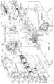
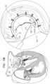
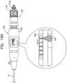
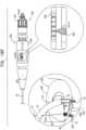
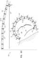
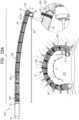
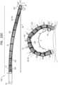
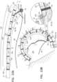
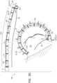
- FIGs. 1-2are schematic illustrations of a multi-component tubular system 10 providing one or more rotationally-controlled steering catheters configured for delivering an implant to a heart of a subject, in accordance with some applications of the present invention.
- Fig. 1shows a distal portion of an implant that comprises an annuloplasty ring structure 222 (i.e., an implant, e.g., an annuloplasty band) comprising a flexible sleeve 26 (shown in the exploded view of Fig. 2 ).
- Sleeve 26typically comprises a braided fabric mesh, e.g., comprising polyethylene terephthalate (such as Dacron (TM)).
- Sleeve 26is typically configured to be placed only partially around a cardiac valve annulus (i.e., to assume a C-shape), and, once anchored in place, to be contracted so as to circumferentially tighten the valve annulus.
- the ring structureis configured to be placed entirely around the valve annulus.
- Sleeve 26has (a) a tubular lateral wall 253 that (i) circumscribes a central longitudinal axis of the sleeve, and (ii) defines the lumen of the sleeve, and (a) at least one end wall 251 (e.g., a distal end wall) having a surface that is substantially transverse to a lateral surface of tubular wall 253.
- end wall 251defines an end wall of annuloplasty ring structure 222.
- annuloplasty ring structure 222comprises a flexible elongated contraction member 226 that extends along sleeve 26.
- Elongated contraction member 226comprises a wire, a ribbon, a rope, or a band, which typically comprises a flexible and/or superelastic material, e.g., nitinol, polyester, stainless steel, or cobalt chrome.
- the wirecomprises a radiopaque material.
- contraction member 226comprises a braided polyester suture (e.g., Ticron).
- contraction member 226is coated with polytetrafluoroethylene (PTFE).
- contraction member 226comprises a plurality of wires that are intertwined to form a rope structure.
- Annuloplasty ring structure 222further comprises an adjustment mechanism 40, which facilitates contracting and expanding of annuloplasty ring structure 222 so as to facilitate adjusting of a perimeter of the annulus and leaflets of the cardiac valve. Adjustment mechanism 40 is described in more detail hereinbelow. Adjustment mechanism 40 comprises a rotatable structure (e.g., a spool, as described hereinbelow) that is disposed within a housing 44. For some applications of the present invention, adjustment mechanism 40 comprises the housing 44. Adjustment mechanism 40 may be surrounded by a braided mesh, coupled (e.g., by being sutured or otherwise coupled) to the braided mesh of sleeve 26. For some applications, adjustment mechanism 40 is coupled to an outer, lateral surface of sleeve 26.
- a braided meshcoupled (e.g., by being sutured or otherwise coupled) to the braided mesh of sleeve 26.
- adjustment mechanism 40is coupled to an outer, lateral surface of sleeve 26.
- System 10comprises an implant-delivery tool.
- system 10comprises a first, outer catheter 12 comprising a sheath configured for transluminal advancement through vasculature of a subject.
- outer catheter 12comprises a sheath configured for advancement through a femoral artery toward an interatrial septum of a heart of a subject.
- a distal end portion 112 of outer catheter 12is configured to pass through the transatrial septum of the subject, and to be oriented in a desired spatial orientation within the left atrium.
- System 10comprises a second catheter, or guide catheter 14, comprising a distal end portion 114 that is configured to pass through catheter 12 (i.e., a primary lumen thereof), to become disposed outside of a distal end 102 of the outer catheter, and to be oriented in a desired spatial orientation within the left atrium.
- catheter 12i.e., a primary lumen thereof
- Distal end portion 112 of outer catheter 12is steerable. That is, distal end portion 112 is deflectable with respect to an immediately more proximal portion of catheter 12 (e.g., by using extracorporeal elements of system 10). Distal end portion 112 comprises a pull ring 11 that is coupled to two or more pull wires 29a and 29b, that are disposed within respective secondary lumens within a lateral wall of catheter 12 (as shown in section A-A of Fig. 2 ). As shown in the exploded view, guide catheter 14 is configured to be concentrically disposed within the lumen of catheter 12. Distal end portion 114 of inner catheter 14 is steerable.
- distal end portion 114is deflectable with respect to an immediately more proximal portion of catheter 14 (e.g., by using extracorporeal elements of system 10).
- Distal end portion 114comprises a pull ring 13 that is coupled to two or more pull wires 31a and 31b, that are disposed within respective secondary lumens within a wall of catheter 14 (as shown in sections A-A and B-B).
- Guide catheter 14is steerable to a desired spatial orientation in order to facilitate advancing and implantation of an implant in a body cavity of the subject.
- outer catheter 12is configured for initial advancement through vasculature of the subject until a distal end 102 of catheter 12 is positioned in the left atrium.
- the distal steerable end portion of catheter 12is then steered such that distal end 102 of catheter 12 is positioned in a desired spatial orientation within the left atrium.
- the steering procedureis typically performed with the aid of imaging, such as fluoroscopy, transesophageal echo, and/or echocardiography.
- guide catheter 14which houses annuloplasty ring structure 222
- at least a portion of steerable distal end portion 114is exposed from distal end 102 of catheter 12 and is thus free for steering toward the annulus of the mitral valve, as is described hereinbelow.
- sleeve 26 and mechanism 40are disposed within a lumen of catheter 14 and are typically aligned longitudinally with a longitudinal axis of catheter 14.
- Mechanism 40is coupled to sleeve 26 in a manner that allows mechanism 40 to move (e.g., to translate) from a state in which it is in line with the longitudinal axis of catheter 14 ( Fig. 2 ) to a state in which it is disposed alongside sleeve 26 ( Fig. 1 ).
- adjustment mechanism 40may be coupled to sleeve 26 via one or more connectors 27, such as sutures, which provide flexible and/or articulated coupling.
- the positioning of adjustment mechanism 40 alongside a portion of sleeve 26exposes a driving interface of the rotational structure (e.g., a driving interface 476, Fig. 16A ), providing access to the interface for an adjustment tool that is subsequently guided toward adjustment mechanism 40 via a guide member 86.
- a driving interface of the rotational structuree.g., a driving interface 476, Fig. 16A
- a flexible, longitudinal guide member 86(e.g., a wire) is coupled to a portion of adjustment mechanism 40 (e.g., a portion of the rotatable structure, as described hereinbelow).
- Guide member 86has a thickness of 0.35-0.45 mm, e.g., 0.4 mm.
- Guide member 86is configured to facilitate guiding of an adjustment tool via guide member 86 and toward the rotatable structure of adjustment mechanism 40.
- the adjustment toolis configured to engage the rotatable structure of adjustment mechanism 40 following implantation of sleeve 26 along the annulus of the cardiac valve.
- Guide member 86extends from adjustment mechanism 40, alongside a portion of distal end portion 114 of guide catheter 14, and into a secondary lumen in the wall of guide catheter 14 via an opening 15 in guide catheter 14.
- Guide member 86extends through the secondary lumen of guide catheter 14 (as shown in sections A-A and B-B in Fig. 2 ) and has a proximal end that is accessible from outside the body of the subject.
- the secondary lumen in the wall of guide catheter 14facilitates passage of guide member 86 through system 10 without interfering with the other concentrically-disposed elongate tubular members that pass concentrically through the lumen of guide catheter 14.
- system 10comprises a plurality of anchors 32, typically between about 5 and about 20 anchors, such as about 10 or about 16 anchors.
- Each anchor 32comprises a tissue-coupling element 60 (e.g., a helical tissue-coupling element), and a tool-engaging head 62 (e.g., a non-helically-shaped portion), fixed to one end of the tissue-coupling element.
- Only one anchor 32is shown in Fig. 2 as being reversibly coupled to a deployment element 38 of an anchor driver 36 of an anchor deployment manipulator 61. However, each of anchors 32 is reversibly couplable to a deployment element 38 of one or more anchor drivers 36.
- deployment manipulator 61is configured to advance within a lumen of sleeve 26 and deploy each anchor 32 from within sleeve 26 through a wall of sleeve 26 and into cardiac tissue, thereby anchoring sleeve 26 around a portion of the valve annulus.
- the insertion of the anchors into the sleeve and deployment of the anchors into cardiac tissueis described in detail hereinbelow.
- anchors 32comprise a biocompatible material such as stainless steel 316 LVM.
- anchors 32comprise nitinol.
- anchors 32are coated fully or partially with a non-conductive material.
- Deployment manipulator 61comprises anchor driver 36 and deployment element 38.
- deployment manipulator 61comprises channel 18.
- sleeve 26is disposed within a lumen of guide catheter 14. Forces are applicable to a proximal end of sleeve 26 via a reference-force tube 19, a distal end of which is coupled to the proximal end of the sleeve.
- an implant-decoupling channel 18is advanceable within a lumen of reference-force tube 19 and within a lumen of sleeve 26.
- a distal end 17 of implant-decoupling channel 18is placeable in contact with an inner wall of sleeve 26, e.g., at a distal end thereof.
- the distal end portion of channel 18may comprise a radiopaque marker 1018.
- tube 19 and sleeve 26are longitudinally and coaxially disposed with respect to each other.
- channel 18is steerable.
- manipulator 61advances within channel 18.
- system 10comprises a plurality of anchor drivers 36 of manipulator 61, each driver 36 being coupled to a respective anchor 32.
- Each driver 36is advanced within channel 18 in order to advance and implant anchor 32 in tissue.
- anchor 32is decoupled from driver 36, as described herein, and driver 36 is removed from within channel 18.
- a subsequent anchor 32is then advanced within channel 18 while coupled to a driver 36 (e.g., a new driver).
- a first one of anchors 32is configured to be deployed through end wall 251 of sleeve 26 into cardiac tissue, when sleeve 26 is positioned along the annulus of the valve. Following the deployment of the first tissue anchor, a distal portion of sleeve 26 is slid distally off a portion of implant-decoupling channel 18.
- a proximal forceis applied to channel 18, while (2) reference-force tube 19 is maintained in place in a manner in which a distal end of tube 19 provides a reference force to sleeve 26, thereby facilitating freeing of a successive portion of sleeve 26 from around channel 18.
- Channel 18is then positioned at a successive location within the lumen of sleeve 26 while tube 19 and/or catheter 14 is steered toward a successive location along the annulus of the valve (as will be described hereinbelow).
- the successive portion of sleeve 26provides a free lumen for advancement of a successive anchor 32 and deployment of the anchor through the wall of the sleeve at the successive portion thereof.
- Such freeing of the successive portion of sleeve 26creates a distance between successive anchors deployed from within the lumen of sleeve 26.
- sleeve 26comprises a plurality of radiopaque markers 25, which are positioned along the sleeve at respective longitudinal sites.
- the markersmay provide an indication in a radiographic image (such as a fluoroscopy image) of how much of the sleeve has been deployed at any given point during an implantation procedure, in order to enable setting a desired distance between anchors 32 along the sleeve.
- the markerscomprise a radiopaque ink.
- the longitudinal sitesare longitudinally spaced at a constant interval.
- the longitudinal distance between the distal edges of adjacent/consecutive markers, and/or the distance between the proximal edges of adjacent markersis set equal to the desired distance between adjacent anchors.
- the markersmay comprise first, second, and third markers, which first and second markers are adjacent, and which second and third markers are adjacent, and the distance between the proximal and/or distal edges of the first and second markers equal the corresponding distance between the proximal and/or distal edges of the second and third markers.
- the distancemay be between 3 and 15 mm, such as 6 mm, and the longitudinal length of each marker may be between 0.1 and 14 mm, such as 2 mm. (If, for example, the distance were 6 mm and the length were 2 mm, the longitudinal gaps between adjacent markers would have lengths of 4 mm.)
- Anchor driver 36typically comprises an elongate and flexible shaft (which is typically tubular) having at least a flexible distal end portion.
- the elongate shaft of driver 36extends within a lumen of channel 18, through system 10 toward a proximal end of a proximal handle portion 101 of system 10.
- the tube of anchor driver 36provides a lumen for slidable advancement therethrough of an elongate rod 130.
- Rod 130facilitates the locking and unlocking of anchor 32 to deployment element 38.
- a proximal end of rod 130is coupled to a component of an anchor-release mechanism 28 at a proximal end of system 10.
- Mechanism 28comprises a housing 135 and a finger-engager 131 that is coupled to the proximal end of rod 130.
- Finger-engager 131is coupled to a housing 135 via a spring 133 (section E-E of Fig. 2 ).
- a proximal end of the tube of anchor driver 36is coupled to housing 135. The physician releases anchor 32 from deployment element 38 when finger-engager 131 is pulled proximally, thereby pulling rod 130 proximally.
- Proximal handle portion 101is supported by a stand having support legs 91 and a handle-sliding track 90.
- Handle portion 101comprises an outer-catheter handle 22, a guide-catheter handle 24, an implant-manipulating handle 126, and anchor-release mechanism 28.
- Handle 22is coupled to a proximal end of outer catheter 12.
- Handle 24is coupled to a proximal portion of guide catheter 14.
- Handle 126is coupled to a proximal portion of reference-force tube 19, and linear movement of handle 126 with respect to handle 24 moves reference-force tube 19 (and thereby typically structure 222) through catheter 14.
- housing 135 of anchor-release mechanism 28is coupled to a proximal portion of the tube of anchor driver 36.
- the relative positioning of each of the concentrically-disposed components of system 10is shown in the exploded view and sections A-A, B-B, C-C, and D-D of Fig. 2 .
- the stand supporting proximal handle portion 101may be moved distally and proximally to control a position of the entire multi-component system 10, particularly so as to adjust a distance of distal end 102 of catheter 12 from the interatrial septum.
- Handle 22comprises a steering knob 210 that is coupled to steering wires 29a and 29b disposed within respective secondary lumens in the wall of outer catheter 12. Rotation of knob 210 adjusts a degree of tension of wires 29a and 29b which, in turn, apply a force to pull ring 11 at the distal end portion of outer catheter 12.
- Such forcesteers the distal end portion of catheter 12 within the atrium of the heart of the subject in a manner in which the distal end portion of catheter 12 is steered in a first steering plane that is typically parallel with the plane of the annulus of the valve (e.g., in a direction from the interatrial septum toward surrounding walls of the atrium).
- the distal end portion of catheter 12may be pre-shaped so as to point downward toward the valve.
- the distal end portion of catheter 12may be pulled to assume an orientation in which the distal end portion points downward toward the valve.
- the distal end portion of catheter 12is not made to point downward toward the valve.
- Handle 24is coupled to track 90 via a first mount 92.
- Mount 92is slidable proximally and distally along track 90 in order to control an axial position of guide catheter 14 with respect to outer catheter 12.
- Mount 92is slidable via a control knob 216.
- control knob 216 of mount 92controls the proximal and distal axial movement of the distal steerable portion of guide catheter 14 with respect to distal end 102 of outer catheter 12.
- Handle 24comprises a steering knob 214 that is coupled to steering wires 31a and 31b disposed within respective secondary lumens in the wall of guide catheter 14.
- Rotation of knob 214adjusts a degree of tension of wires 31a and 31b which, in turn, apply a force to pull ring 13 at the distal end portion of guide catheter 14.
- Such forcesteers the distal end portion of catheter 14 in a second steering plane within the atrium of the heart of the subject, typically downward and toward the annulus of the cardiac valve.
- the distal end portion of guide catheter 14is steered in the second plane that is substantially perpendicular with respect to the first plane in which the distal end portion of outer catheter 12 is steered.
- the combined steering of the respective distal end portions of catheters 12 and 14directs sleeve 26 down toward the annulus (e.g., via the steering of the distal end portion of catheter 14) and along the perimeter of annulus (e.g., from the posterior section of the valve to the anterior section of the valve, and vice versa), via the steering of the distal end portion of catheter 12.
- handle 22may be tilted by the operating physician, in order to further adjust a position of the distal end of catheter 12.
- Handle 126is slidably coupled to track 90 via a second mount 93.
- Mount 93is slidable proximally and distally along track 90, in order to control an axial position of reference-force tube 19 and at least a proximal portion of sleeve 26 with respect to guide catheter 14.
- mount 93comprises a control knob 95.
- control knob 95reversibly locks mount 93 to track 90, thereby reversibly inhibiting sliding of the mount along the track.
- turning of control knob 95may cause sliding of mount 93 along track 90 (e.g., acting like a rack and pinion).
- friction between (i) reference-force tube 19 and (ii) catheter 14 and/or handle 24reduces a likelihood of inadvertent sliding of tube 19 through catheter 14, and thereby obviates the need for locking of mount 93 to track 90.
- such movement of tube 19 and at least the proximal portion sleeve 26moves the proximal portion of sleeve 26 toward a desired portion of tissue of the annulus of the valve during deployment of anchors 32 from within the lumen of sleeve 26, as is described hereinbelow.
- channel 18is pulled proximally, while (2) reference-force tube 19 is maintained in place.
- a proximal end of channel 18is coupled to a knob 94 which adjusts an axial position of channel 18 proximally and distally with respect to reference-force tube 19 and sleeve 26.
- handle portion 101comprises a release-decision-facilitation member 127, such as a latch or button, that automatically engages when a given length of sleeve 26 has advanced off channel 18 (e.g., when channel 18 is at a given position with respect to tube 19); typically just before sleeve 26 becomes completely decoupled from channel 18. Engagement of member 127 inhibits proximal movement of channel 18 with respect to tube 19, thereby reducing a likelihood of (e.g., preventing) inadvertent release of sleeve 26.
- a release-decision-facilitation member 127such as a latch or button
- the operating physicianIn order to release sleeve 26 (e.g., to decouple channel 18 from the sleeve), the operating physician must disengage member 127, such as by pushing the button, before continuing to withdraw channel 18 proximally. Typically, when engaged, member 127 also inhibits distal movement of channel 18 with respect to tube 19.
- Handle portion 101(comprising handles 22, 24, and 126 and anchor-release mechanism 28) has a length L1 of between 65 and 85 cm, e.g., 76 cm.
- a majority of the body portion of outer-catheter handle 22is disposed at a non-zero angle with respect to a longitudinal axis 7 of the multiple components of system 10.
- the steering mechanism provided by handle 22 in order to steer the distal end portion of catheter 12is disposed within the portion of handle 22 that is disposed at the non-zero angle with respect to axis 7.
- Handle 22comprises an in-line tubular portion which is longitudinally disposed in-line along axis 7 and coaxially with respect to handles 24 and 126 and release mechanism 28.
- the in-line tubular portionis shaped so as to define a lumen for inserting guide catheter 14 therethrough and subsequently into the lumen of outer catheter 12.
- the in-line tubular portionhas a length L24 of between 7 and 11 cm, e.g., 7 cm. Such spatial orientation of the majority of handle 22 at an angle with respect to axis 7 reduces an overall functional length of handle portion 101.
- a guidewire 2244extends alongside sleeve 26 to facilitate positioning of sleeve 26 along the annulus.
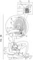
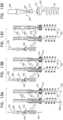
- FIGs. 3A-G , and 4A-Bare schematic illustrations of steps in the implantation of an annuloplasty ring structure to repair a mitral valve. This procedure is one exemplary procedure that can be performed using system 10.
- Anchor deployment manipulator 61is advanced into a lumen of sleeve 26, and, from within the lumen, deploys the anchors through a wall of the sleeve and into cardiac tissue, thereby anchoring the sleeve around a portion of the valve annulus.
- annuloplasty ring structure 222is implemented using techniques described in US Application 12/437,103, filed May 7, 2009 which published as US 2010/0286767 , and/or US Application 12/689,635, filed January 19, 2010 which published as US 2010/0280604 , both of which are assigned to the assignee of the present application. As described hereinabove, annuloplasty ring structure 222 comprises adjustment mechanism 40.
- the adjustment mechanismcomprises a rotatable structure, such as a spool, arranged such that rotation of the rotatable structure contracts the implant structure.
- the implantfurther comprises a longitudinal member, such as a wire, which is coupled to the adjustment mechanism.
- An adjustment toolis provided for rotating the rotatable structure. The tool is configured to be guided along (e.g., over, alongside, or through) the longitudinal member, to engage the rotatable structure, and to rotate the rotatable structure in response to a rotational force applied to the tool.
- the proceduretypically begins by advancing a semi-rigid guidewire into a right atrium 220 of the subject.
- the procedureis typically performed with the aid of imaging, such as fluoroscopy, transesophageal echo, and/or echocardiography.
- the guidewireprovides a guide for the subsequent advancement of outer catheter 12 therealong and into the right atrium. Once a distal portion of catheter 12 has entered the right atrium, the guidewire is retracted from the subject's body.
- Catheter 12typically comprises a 14-24 F sheath, although the size may be selected as appropriate for a given subject.
- Catheter 12is advanced through vasculature into the right atrium using a suitable point of origin typically determined for a given subject. For example:
- catheter 12is advanced through inferior vena cava 223 of the subject (as shown) and into right atrium 220 using a suitable point of origin typically determined for a given subject.
- Catheter 12is advanced distally until the sheath reaches the interatrial septum, and the guidewire is withdrawn.
- a resilient needle and a dilatorare advanced through catheter 12 and into the heart.
- the dilatorIn order to advance catheter 12 transseptally into left atrium 224, the dilator is advanced to the septum, and the needle is pushed from within the dilator and is allowed to puncture the septum to create an opening that facilitates passage of the dilator and subsequently catheter 12 therethrough and into left atrium 224.
- the dilatoris passed through the hole in the septum created by the needle.
- the dilatoris shaped to define a hollow shaft for passage along the needle, and the hollow shaft is shaped to define a tapered distal end. This tapered distal end is first advanced through the hole created by the needle.
- the holeis enlarged when the gradually increasing diameter of the distal end of the dilator is pushed through the hole in the septum.
- a distal-most end 102 of catheter 12is tapered so as to facilitate passage of at least part of distal portion 112 of catheter 12 through the opening in the septum.
- catheter 12The advancement of catheter 12 through the septum and into the left atrium is followed by the extraction of the dilator and the needle from within catheter 12.
- portion 112is steered (i.e., deflected) in a first steering plane, typically parallel to a plane of the annulus of mitral valve 230.
- the steering of the distal portion of catheter 12is performed via steering knob 210 of handle 22 in handle portion 101 (in Fig. 2 ).
- catheter 14containing annuloplasty ring structure 222 (with a distal portion of channel 18 disposed within sleeve 26 thereof), is advanced through catheter 12 into left atrium 224.
- the distal portion of channel 18is loaded into sleeve 26, and structure 222 is loaded into catheter 14.
- Distal end portion 114 of catheter 14extends beyond distal end 102 of catheter 12.
- Distal end portion 114is then steered (i.e., deflected) in a second steering plane, typically perpendicular with respect to the steering plane of catheter 12, and further typically toward the annulus of valve 230.
- the steering of the distal portion of catheter 14is performed via steering knob 214 of handle 24 in handle portion 101 (in Fig. 2 ).
- FIG. 3Ashows annuloplasty ring structure 222, comprising sleeve 26 and adjustment mechanism 40, having been advanced, via catheter 14, to a mitral valve 230.
- adjustment mechanism 40is disposed distal to (i.e., in front of) sleeve 26.
- adjustment mechanism 40is disposed on the longitudinal axis of sleeve 26 (e.g., collinearly with the sleeve), so as to advantageously maintain a small cross-sectional diameter of the implant for transluminal delivery.
- a proximal end of connector 27is disposed proximally to mechanism 40 (e.g., by being fixed to a portion of sleeve 26 proximal to mechanism 40 or by being accessible outside the body of the subject).
- a distal end of connector 27is coupled (e.g., by being fixedly coupled by a knot or other mechanical coupling) to mechanism 40.
- Guide member 86described hereinabove, typically extends distally from catheter 14, between end wall 251 of sleeve 26 and adjustment mechanism 40, and there is coupled to the adjustment mechanism.
- connectors 27facilitate this technique by making mechanism 40 flexibly and/or articulatably coupled to sleeve 26.
- connectors 27are tensioned or relaxed to move mechanism 40 with respect to sleeve 26 to reposition mechanism 40.
- guide member 86is tensioned or relaxed in order to reposition mechanism 40.
- adjustment mechanism 40(and typically at least end wall 251 of sleeve 26) from catheter 14, the adjustment mechanism is moved away from end wall 251. Typically, this is achieved by guide member 86 being moved proximally such that mechanism 40 moves (e.g., translates, deflects, and/or rotates) away from the longitudinal axis of the sleeve, typically to become disposed laterally from sleeve 26.
- Fig. 3Bshows mechanism 40 having translated to such a position.
- mechanism 40 away from end wall 251 of sleeve 26advantageously allows end wall 251 of sleeve 26 to be placed against an atrial surface of an annulus 240, and a first one of anchors 32 to be driven through end wall 251 of the sleeve and into the annulus ( Fig. 3C ).
- end wall 251 of sleeve 26is positioned in a vicinity of a left fibrous trigone 242 of an annulus 240 of mitral valve 230.
- distal end wall 251 of sleeve 26is shown schematically in the cross-sectional view of the heart, although left trigone 242 is in reality not located in the shown cross-sectional plane, but rather out of the page closer to the viewer.
- the distal end of sleeve 26is positioned in a vicinity of a right fibrous trigone 244 of the mitral valve (configuration not shown).
- deployment manipulator 61deploys the first one of anchors 32 through the wall of sleeve 26 (by penetrating and passing through the wall of the sleeve (i) in a direction parallel to a central longitudinal axis of deployment manipulator 61, or anchor driver 36, through the distal end of channel 18, and/or (ii) parallel to a central longitudinal axis of tissue-coupling element 60 of anchor 32) into cardiac tissue near the trigone.
- deployment element 38is decoupled from anchor 32.
- Anchors 32are typically deployed from a distal end of manipulator 61 while the distal end is positioned such that a central longitudinal axis through the distal end of manipulator 61 forms an angle with a surface of the cardiac tissue of between about 20 and 90 degrees, e.g., between 45 and 90 degrees, such as between about 75 and 90 degrees, such as about 90 degrees.
- anchors 32are deployed from the distal end of manipulator 61 into the atrial surface of the cardiac tissue in a direction parallel to the central longitudinal axis through the distal end of manipulator 61.
- Such an angleis typically provided and/or maintained by channel 18 being more rigid than sleeve 26.
- Distal end 17 of channel 18is typically brought close to the surface of the cardiac tissue (and the wall of sleeve 26 that is disposed against the surface of the cardiac tissue), such that little of each anchor 32 is exposed from channel 18 before penetrating the sleeve and the tissue.
- distal end 17 of channel 18may be placed (e.g., pushed) against the wall of the sleeve, sandwiching the sleeve against the cardiac tissue.
- distal end 17 of channel 18stabilizes the distal end during deployment and anchoring of each anchor 32, and thereby facilitates anchoring.
- pushing of distal end 17 against the cardiac tissue (via the wall of the sleeve)temporarily deforms the cardiac tissue at the site of contact. This deformation may facilitate identification of the site of contact using imaging techniques (e.g., by identifying a deformation in the border between cardiac tissue and blood), and thereby may facilitate correct positioning of the anchor.
- distal end 17 of channel 18typically the entire circular surface of distal end 17 of channel 18 is disposed in contact with the wall of sleeve 26 that is disposed against the surface of the cardiac tissue. As shown, distal end 17 is the lower-most circular tip of channel 18 and defines a distal opening of channel 18. In the configuration in which channel 18 is positioned in order to sandwich the portion of sleeve 26 against annulus 240, the distal end 17 is disposed in parallel with a planar surface 255 of the tissue of the annulus.
- end wall 251aligns against the tissue of annulus 240 in a manner in which a surface of end wall 251 is disposed in parallel with a planar surface of the tissue of annulus 240. Additionally, distal end 17 of implant-decoupling channel 18 flattens end wall 251 against the tissue of annulus 240 in a manner in which channel 18 sandwiches end wall 251 between (1) distal end 17 of the channel, and (2) the portion of the tissue of annulus 240 at the planar surface into which a first one of anchors 32 is implanted.
- end wall 251lies flat against the tissue of annulus 240 in parallel with the planar surface, while at least a distal portion of lateral wall 253 is disposed substantially perpendicularly with respect to the portion of the tissue of annulus 240 at the planar surface into which the first one of anchors 32 is implanted.
- anchor 32is implanted using channel 18 and manipulator 61 contained within sleeve 26 of annuloplasty structure 222 while at least a portion of annuloplasty structure 222 (e.g., a proximal portion) is contained within surrounding catheter 14.
- a distal portion of sleeve 26is decoupled from a portion of implant-decoupling channel 18.
- channel 18is pulled proximally, while (2) reference-force tube 19 is maintained in place in a manner in which a distal end of tube 19 provides a reference force to sleeve 26 in order to facilitate freeing of a successive portion of sleeve 26 from around channel 18.
- channel 18is pulled proximally, while (2) reference-force tube 19 is maintained in place.
- An indicator 2120 on handle 126provides an indication of how much channel 18 is withdrawn from within sleeve 26 (i.e., how much the delivery tool is decoupled from sleeve 26, and how much the sleeve has advanced off channel 18 and against tissue).
- a proximal end of channel 18is coupled to a knob 94 ( Fig. 2 ) which adjusts an axial position of channel 18 proximally and distally with respect to reference-force tube 19 and sleeve 26.
- deployment manipulator 61is repositioned along annulus 240 to another site selected for deployment of a second one of anchors 32.
- Figs. 4A and 4Bare schematic illustrations that show steps between the state shown in Fig. 3C and the state shown in Fig. 3D .
- Step C of each of Figs. 4A and 4Bshows a state that is generally equivalent to the state shown in Fig. 3D .
- anchor driver 36is decoupled from anchor 32 and is retracted through channel 18 prior to retracting channel 18 through sleeve 26 and repositioning channel 18.
- anchor driver 36remains coupled to anchor 32 during the retraction of channel 18 though sleeve 26.
- anchor driver 36provides a reference force (e.g., a distally-directed reference force) that holds in place anchor 32 and the anchored portion of sleeve 26 while channel 18 is retracted, e.g., reducing a pulling force on anchor 32.
- a reference forcee.g., a distally-directed reference force
- a methodcomprising: (1) percutaneously advancing toward a tissue of a subject structure 222, while a distal portion of channel 18 is disposed within the lumen defined by sleeve 26, such that a distal opening of the channel is disposed at a first portion of the sleeve; (2) anchoring the first portion of the sleeve to the tissue by using anchor driver 36 to drive tissue-coupling element 60 of a first anchor 32 through the distal opening of the channel, through the sleeve, and into the tissue; (3) subsequently, while providing a distally-directed reference force to the first anchor 32 via driver 36, proximally withdrawing the distal portion of channel 18 such that the distal opening of the channel is disposed at a second portion of the sleeve; (4) subsequently, proximally withdrawing driver 36 through the channel; and (5) subsequently, anchoring the second portion of the sleeve to the tissue by driving tissue-coupling element 60 of a second anchor 32 through the distal opening of the
- Such repositioning of manipulator 61is accomplished by performing one or more of the following:
- the first tissue anchoris deployed most distally in the sleeve (generally at or within a few millimeters of the distal tip of the sleeve), and each subsequent anchor is deployed more proximally, such that the sleeve is gradually decoupled from channel 18 of deployment manipulator 61 in a distal direction during the anchoring procedure (i.e., channel 18 is withdrawn from within sleeve 26, and handle 126 is moved distally so as to retract the tool to make the successive proximal portion sleeve 26 ready for implantation of a subsequent anchor).
- the already-deployed first one of anchors 32holds the anchored end of sleeve 26 in place, so that the sleeve is drawn from the site of the first tissue anchor towards the site of the second tissue anchor.
- a distal portion 257 of sleeve 26i.e., the portion of the sleeve that is proximal to end wall 251 is positioned in a vicinity of tissue of annulus 240.
- Fig. 3Dshows distal portion 257 of sleeve 26 (i.e., the portion of the sleeve that is proximal to end wall 251) having been decoupled from a portion of channel 18 by retracting channel 18 proximally.
- the portion of sleeve 26 therebetweenmay remain tubular in shape, or may become flattened.
- Fig. 3Eshows a second tissue anchor 32 (shown as a second tissue anchor 32b) being deployed through a portion of lateral wall 253 of sleeve 26.
- the first one of anchors 32 deployed through end wall 251is labeled as anchor 32a.
- Deployment manipulator 61deploys the second tissue anchor by driving the anchor to penetrate and pass through the wall of sleeve 26 into cardiac tissue at the second site.
- anchor 32bis implanted using channel 18 and manipulator 61 contained within sleeve 26 of annuloplasty structure 222 while at least a portion of annuloplasty structure 222 (e.g., a proximal portion) is contained within surrounding catheter 14.
- anchors 32a and 32bare each deployed from a distal end of manipulator 61 while the distal end is positioned such that a central longitudinal axis through the distal end of manipulator 61 forms an angle with a surface of the cardiac tissue of between about 20 and 90 degrees, e.g., between 45 and 90 degrees, such as between about 75 and 90 degrees, such as about 90 degrees.
- anchors 32are deployed from the distal end of manipulator 61 into the atrial surface of the cardiac tissue in a direction parallel to the central longitudinal axis through the distal end of manipulator 61.
- Such an angleis typically provided and/or maintained by channel 18 being more rigid than sleeve 26.
- Distal end 17 of channel 18is typically brought close to the surface of the cardiac tissue (and the wall of sleeve 26 that is disposed against the surface of the cardiac tissue), such that little of anchor 32b is exposed from channel 18 before penetrating the sleeve and the tissue.
- distal end 17 of channel 18may be placed (e.g., pushed) against the wall of the sleeve, sandwiching the sleeve against the cardiac tissue.
- a portion of the lateral wall of sleeve 26aligns against the tissue of in a manner in which a surface of the portion of the lateral wall is disposed in parallel with the planar surface of the tissue. Additionally, distal end 17 of channel 18 flattens the portion of the lateral wall against the tissue of annulus 240 in a manner in which channel 18 sandwiches the portion of the lateral wall between (1) distal end 17 of implant-decoupling channel, and (2) the portion of the tissue of annulus 240 at the planar surface into which second tissue anchor 32b is implanted.
- the portion of the lateral wall being anchoredlies flat against the tissue of annulus 240 (parallel with the planar surface thereof), while the remaining portion of the tubular lateral wall is disposed substantially perpendicularly with respect to the portion of the tissue into which second tissue anchor 32b is implanted.
- first and second tissue anchors 32a and 32bextend in a substantially same direction and into a common, substantially planar surface of a valve annulus, despite that first tissue anchor 32a is deployed through end wall 251 of sleeve 26, and tissue anchor 32b is deployed through lateral wall 253 of the sleeve.
- anchors 32a and 32bare disposed with respect to each other at an angle of between 0 and 45 degrees, e.g., between 0 and 30 degrees, e.g., between 0 and 20 degrees.
- a maximum distance L10 between first tissue anchor 32a and a point of anchoring of second tissue anchor 32bis provided by the length of sleeve 26 that has been decoupled from the portion of channel 18 (e.g., by the distance that channel 18 has been retracted from sleeve 26, e.g., between 3 and 15 mm, e.g., 8 mm). That is, for some applications, second tissue anchor 32b may be placed anywhere within a circle having a radius that equals L10, centered on the first tissue anchor (e.g., indicated by arc 1928).
- sleeve 26thereby serves as a constraining member (e.g., a tether) that is used to facilitate positioning of second tissue anchor 32b.
- Distance L10is thereby set by the operating physician retracting channel 18 from sleeve 26 by a particular distance.
- Fig. 3Fshows the entire length of sleeve 26 having been anchored, via a plurality of anchors 32, to annulus 240, as described hereinabove.
- the deployment manipulatori.e., deployment manipulator 61 described herein but not shown in Fig. 3F
- the deployment manipulatoris repositioned along the annulus to additional sites, at which respective anchors are deployed, until the last anchor is deployed in a vicinity of right fibrous trigone 244 (or left fibrous trigone 242 if the anchoring began at the right trigone).
- the last anchoris not deployed in the vicinity of a trigone, but is instead deployed elsewhere in a vicinity of the mitral valve, such as in a vicinity of the anterior or posterior commissure.
- system 10is removed, leaving behind annuloplasty ring structure 222, and guide member 86 coupled thereto.
- Adjustment tool 87typically comprises a rotation tool, and is configured to actuate (e.g., rotate) adjustment mechanism 40, so as to tension contraction member 226, and thereby contract sleeve 26, as described hereinabove.
- adjustment mechanism 40comprises a housing which houses a spool, i.e., a rotatable structure, to which a first end of contraction member 226 is coupled.
- the spoolis configured to adjust a perimeter of annuloplasty ring structure 222 by adjusting a degree of tension of contraction member 226 that is coupled at a first portion of member 226 to the spool.
- the contraction member 226extends along sleeve 26 and a second portion of contraction member 226 (i.e., a free end portion) is coupled to a portion of sleeve 26 such that upon rotation of the spool in a first rotational direction, the contraction member is pulled toward adjustment mechanism 40 in order to contract annuloplasty ring structure 222. It is to be noted that the contraction of structure 222 is reversible. That is, rotating the spool in a second rotational direction that opposes the first rotational direction used to contract the annuloplasty structure, unwinds a portion of contraction member 226 from around the spool.
- Unwinding the portion of contraction member 226 from around the spoolthus feeds the portion of contraction member 226 back into sleeve 26 of structure 222, thereby slackening the remaining portion of contraction member 226 that is disposed within the sleeve.
- the annuloplasty structuregradually relaxes and expands (i.e., with respect to its contracted state prior to the unwinding).
- Adjustment mechanism 40typically comprises a locking mechanism that prevents actuation of the adjustment mechanism (e.g., rotation of the spool) after contraction member 226 has been tightened.
- locking techniquesmay be used that are described with reference to Fig. 4 of US Patent 8,241,351 to Cabiri .
- Tool 87is used to rotate the spool of adjustment mechanism 40 in order to tighten structure 222 by adjusting a degree of tension of contraction member 226 (not shown in Fig. 3G ).
- adjustment tool 87 and guide member 86are removed from the heart.
- a distal portion of guide member 86may be left within the heart of the subject and the proximal end may be accessible outside the body, e.g., using a port.
- adjustment mechanism 40may be accessed at a later stage following initial implantation and adjustment of ring structure 222 (e.g., as described with reference to Figs. 16A-18K ).
- annuloplasty ring structure 222is implanted by right or left thoracotomy, mutatis mutandis.
- Figs. 3A-Gare schematic illustrations of techniques for use with an excess portion 261 of sleeve 26.
- an excess portion 261 of sleeve 26may be present at the proximal portion of sleeve.
- excess portion 261may be anchored to an atrial surface, such as an atrial wall, using anchors delivered via the lumen of sleeve 26, as described hereinabove, mutatis mutandis , as shown in Fig. 5A .
- excess portion 261may be anchored to the atrial surface using anchors driven from outside of sleeve 26, laterally through the sleeve, such that each anchor passes through the lateral wall of the sleeve twice (e.g., on opposite sides of the lumen of the sleeve), as shown in Fig. 5B .
- a methodcomprising: (1) percutaneously advancing toward a tissue of a subject structure 222, while a distal portion of a channel 18 is disposed within the lumen of sleeve 26, such that a distal opening of the channel is disposed at a first portion of the sleeve; (2) anchoring the first portion of the sleeve to a first tissue site by using anchor driver 36 to drive tissue-coupling element 60 of a first anchor 32 through the distal opening of the channel, through the first portion of the sleeve (e.g., through end wall 251 or lateral wall 253), and into the first tissue site; (3) pressing a second portion of the sleeve (i.e., excess portion 261) against a second tissue site; and (4) anchoring the second portion of the sleeve to the second tissue site by driving tissue-coupling element 60 of a second anchor 32 from outside the lumen, through opposing sides of the lateral wall at the second portion of the sleeve, and into the
- the second portioni.e., the excess portion
- the second tissue sitee.g., the atrial wall
- a transluminal (e.g., transfemoral) approach to the mitral valve via transseptal puncturetypically provides access more directly and/or easily to the region of the anterior commissure (e.g., including left fibrous trigone 242) than to the region of the posterior commissure (e.g., including right fibrous trigone 244). It may therefore be advantageous to position and anchor distal end wall 251 of sleeve 26 in the vicinity of the left fibrous trigone; the positioning of the first point of anchoring of structure 222 may be more difficult than the positioning of subsequent points of anchoring (e.g., due to guidance provided by sleeve 26; Fig. 3E ). Due to this same reason of accessibility, it may also be advantageous to deliver adjustment tool 87 to the region of the anterior commissure (as shown in Fig. 3G ).
- System 10(e.g., structure 222 thereof) is configured to facilitate exploitation of these two advantages:
- adjustment mechanism 40being disposed at a distal end of sleeve 26, and being movable away from the longitudinal axis of the sleeve, (1) the first tissue anchor may be driven through end wall 251 into the region of the anterior commissure, despite the adjustment mechanism having previously been obstructively positioned, and (2) the adjustment tool may be delivered to the region of the anterior commissure because the adjustment mechanism is disposed in that region.
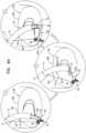
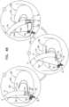
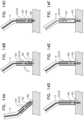
- Figs. 6A-B and 7A-Bare schematic illustrations of steering of catheters 12 and 14.
- distal end portion 112 of catheter 12is steerable in a first steering plane
- distal end portion 114 of catheter 14is steerable in a second steering plane, typically perpendicular to the first steering plane.
- catheter 12is steered in a steering plane that is parallel with the plane of the annulus of the valve (e.g., as shown in Fig. 6A )
- catheter 14is steered downward and toward the annulus of the valve (e.g., as shown in Fig.
- angle alpha_1is formed between (i) plane 241 of the annulus, and (ii) an exit direction 105 from distal end 104 of catheter 14.
- Exit direction 105is typically collinear with the central longitudinal axis through the distal end of manipulator 61, and/or the central longitudinal axis of tissue-coupling element 60 of anchor 32.
- angle alpha_1is greater than an angle alpha _3 formed between plane 241 and an exit direction 103 from distal end 102 of catheter 12.
- catheter 12may be steered in a different steering plane, such that catheter 14 may approach the tissue from a different angle, such that an anchor 32 may penetrate the tissue at a different angle of attack.
- catheter 12may be steered downward and toward the annulus of the valve, and catheter 14 may be steered such that an angle alpha _2 (formed between the plane of the annulus and the central longitudinal axis through the distal end of manipulator 61) is smaller than angle alpha_1.
- angle alpha _2is typically smaller than an angle alpha _4 formed between plane 241 and exit direction 103.
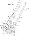
- FIGS. 8A-B , 9 , 10A-C , 11 , and 12A-Bare schematic illustrations of tissue anchors, and the use of the tissue anchors for implantation of structure 222.
- Fig. 8Ashows tissue anchor 32, described hereinabove.
- tissue-coupling element 60is typically helical, and has a central longitudinal axis 33 (which, when element 60 is helical, is an axis of rotation of element 60).
- Tool-engaging head 62has a width d1
- tissue-coupling element 60has a width (e.g., a helix diameter) d2 that for some applications is about the same as width d1.
- Width d1 and width d2are each smaller than the diameter of the lumen of channel 18, thereby facilitating delivery of anchor 32 through channel 18, as described hereinabove.
- a greatest transverse width of anchor 32is smaller than the diameter of the lumen of channel 18.
- Width d2is typically between 0.1 and 0.5 cm (e.g., 0.25 cm).
- Element 60has a helix length d7 that is typically 0.3-0.9 cm, such as 0.3-0.65 cm (e.g., 0.55 cm), and a helix pitch d8 that is typically 0.05-0.3 cm (e.g., 0.12 cm).
- element 60has a helix wire thickness d9 of 0.02-0.1 cm (e.g., 0.05 cm).
- Fig. 8Bshows a tissue anchor 332, which is typically identical to tissue anchor 32 except where noted.
- Anchor 332comprises a tool-engaging head 362, which is typically (but not necessarily) identical to head 62 of anchor 32.
- Anchor 332further comprises a tissue-coupling element 360, and has a central longitudinal axis 333.
- a width d3 of head 362is typically smaller than the diameter of the lumen of channel 18, whereas a width d4 of tissue-coupling element 360 is greater than the diameter of the lumen of the channel (and is therefore greater than width d2).
- widths d1, d2, and d3, and the diameter of the lumen of channel 18may each be 2-3 mm, and width d4 (which is typically the greatest transverse width of anchor 332) may be 3-4 mm (e.g., about 3.4 mm).
- Tissue-coupling element 360therefore typically protrudes radially outward from longitudinal axis 333 further than does head 362, by a distance d5.
- width d3may also be greater than the diameter of the lumen of channel 18.
- the larger width of element 360 compared to that of element 60provides increased anchoring strength. It is hypothesized that for some applications this increased anchoring strength is particularly useful for the first anchor used to anchor structure 222 (e.g., the anchor that penetrates end wall 251), due to increased forces exerted on that anchor compared to, for example, anchors further along sleeve 26. Due to width d4 being greater than the diameter of the lumen of channel 18, anchor 332 cannot be advanced through channel 18 in the same manner as anchor 32.
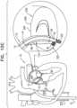
- Figs. 9-12Bshow techniques for anchoring structure 222 (e.g., the distal end of sleeve 26) using anchor 332.
- tissue-coupling element 360has a helix wire thickness that is generally the same as thickness d9.
- Tissue-coupling element 360typically has a helix length that is generally the same as length d7.
- a helix pitch d10 of element 360is different to pitch d8.
- pitch d10may be smaller than pitch d8, so as to maintain the helix length of element 360 as generally the same as length d7.
- a helix angle alpha_6(the angle between the helix and its central longitudinal axis) of element 360 is different to a helix angle alpha_5 of element 60.
- angle alpha_6may be greater than angle alpha_5, so as to maintain the helix length of element 360 as generally the same as length d7.
- At least tissue-coupling element 360 of anchor 332is disposed outside of distal end 17 of channel 18 at the time that channel 18 is loaded into the lumen of the sleeve.
- deployment element 38 of anchor driver 36may be advanced, without an anchor coupled thereto, through channel 18, and subsequently coupled to head 362 of anchor 332.
- An assembly comprising element 38 (and optionally head 362)may then be retracted into channel 18 before the channel, anchor 332, and driver 36 are advanced together into sleeve 26.
- this assemblyis advanced through catheter 14 (and out of the distal end thereof) prior to being advanced into sleeve 26. Therefore, tissue-coupling element 360 does not require passage through channel 18, thereby facilitating the use of anchor 332.
- tissue-coupling element 360is disposed (i) outside of distal end 17 of channel 18, and (ii) inside the lumen of sleeve 26. This may be understood by comparing Fig. 9 with Fig. 1 .
- the steps shown in Figs. 10A-Cgenerally correspond to the steps shown in Figs. 3A-C , but with element 360 disposed outside of distal end 17 of channel 18, and inside the lumen of sleeve 26.
- a plurality of anchors 32are used to anchor the remainder of structure 222, as described hereinabove, mutatis mutandis.
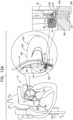
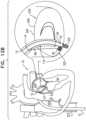
- tissue-coupling element 360is disposed (i) outside of distal end 17 of channel 18, and (ii) outside of sleeve 26, e.g., having been driven through sleeve 26 (e.g., end wall 251 thereof). This may be understood by comparing Fig. 11 with Fig. 9 (and/or Fig. 1 ).
- the steps shown in Figs. 12A-Bgenerally correspond to the steps shown in Figs. 10B-C , but with element 360 disposed outside of sleeve 26.
- Tissue anchor 332typically has a straight and/or central stem portion 364 that facilitates subsequent closure of this gap by allowing free rotation of the anchor within the sleeve, e.g., as is known in the art for captive screws. This feature is described in more detail in WO 2014/064694 to Sheps et al. .
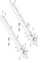
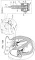
- FIGs. 13A-D and 14A-Fare schematic illustrations of a system 400, comprising a tissue anchor 402, an anchor driver 404, and a lance 406, and techniques for use with the system.
- Anchor driver 404is typically identical to anchor driver 36 described herein, and is typically substitutable for anchor driver 36, mutatis mutandis. Except for where noted, tissue anchor 402 is typically identical to tissue anchor 32 described herein, and is substitutable for tissue anchor 32, mutatis mutandis.
- Anchor driver 404comprises an elongate shaft 408 (which is typically tubular) and a deployment manipulator 410 coupled to a distal end of the shaft.
- Tissue anchor 402comprises a tissue-coupling element, which in Figs. 13A-14F is shown as element 60, but which could comprise a different tissue-coupling element.
- Lance 406serves two functions: (1) to facilitate reversible locking of driver 404 to anchor 402, and (2) to stabilize system 400 at the tissue prior to driving of anchor 402 into the tissue.
- System 400is advanced while a distal tip of lance 406 extends distally past a distal tip of tissue-coupling element 60 (e.g., in the state shown in Fig. 13A ), such that the lance engages the tissue before element 60 does ( Fig. 14A ). Lance 406 penetrates the tissue, thereby stabilizing system 400 at the tissue.
- system 400is used in combination with a catheter system that facilitates pivoting (i.e., deflection) of system 400 about the point at which lance 406 penetrates the tissue.
- a catheter systemmay comprise catheter 14 (as shown), catheter 12, and/or other elements of system 10.
- lance 406can penetrate the tissue at the correct location but the incorrect orientation (e.g., angle) ( Fig. 14A ), and system 400 can be subsequently deflected about that location (e.g., using the lance as a pivot) so as to obtain the correct orientation (e.g., the correct angle of attack for anchor 402) ( Fig. 14B ).
- Anchor 402is typically driven at least partway into the tissue before partially retracting lance 406 ( Figs. 14C-D ).
- Fig. 13Bshows lance 406 in this partly retracted position.
- the presence of lance 406 within deployment manipulator 410retains the deployment manipulator locked to anchor 402 (e.g., to a tool-engaging head 412 thereof).
- deployment manipulator 410may comprise one or more detents 414 that are held in a locking position (e.g., radially outward) by lance 406.
- the partial retraction of lance 406 shown in Fig. 13Bdoes not remove the lance from deployment manipulator 410, and so the manipulator remains locked to anchor 402.
- Fig. 14Dshows anchor 402 fully anchored to the tissue, and lance 406 partially retracted. Subsequent to the anchoring, lance 406 is retracted further, thereby unlocking deployment manipulator 410 from anchor 402 ( Figs. 14E ), e.g., due to detents 414 responsively moving radially inward, as shown in Fig. 13C . Driver 404 may then be decoupled from anchor 402 ( Figs. 14F and 13D ).
- Apparatuscomprising (1) an anchor, comprising (a) an anchor head, and (b) a tissue-engaging member, coupled to the anchor head, extending distally away from the anchor head until a distal tip of the tissue-engaging member, and configured to anchor the anchor to the tissue; (2) an anchor driver, comprising: (a) a longitudinal shaft, having a flexible distal portion and a distal end, (b) a deployment element at the distal end of the shaft, reversibly lockable to the anchor head, and reversibly movable between (i) a locked state that retains locking between the deployment element and the anchor head, and (ii) an unlocked state that unlocks the deployment element from the anchor head, and (c) a tissue-piercing lance, reversibly movable between an extended state in which (i) the lance extends distally from the shaft, (ii) while the deployment element is locked to the anchor head, the lance extends distally past the distal tip of the anchor,
- Apparatuscomprising (1) a percutaneous catheter; (2) an implant, dimensioned to be advanced into the subject via the catheter; (3) an anchor-delivery channel, shaped to define a lumen therethrough, the lumen having a diameter, and the channel being dimensioned to be disposable within the catheter; (4) at least one anchor, comprising an anchor head coupled to a tissue-coupling element, the anchor head defining an aperture therethrough, and (5) an anchor driver (i) comprising a stem, and a driver head coupled to the distal end of the stem, the driver head being reversibly couplable to the anchor head, (ii) configured to advance the anchor through the lumen of the channel while the driver head is coupled to the anchor head, (iii) further comprising a lance that is reversibly extendable with respect to the driver head, such that when the driver head is coupled to the anchor head, extension of the lance causes the lance to slide through the aperture such that a tip of the lance becomes disposed distally beyond a distal
- Apparatuscomprising (1) an anchor, comprising (i) an anchor head, having a proximal side and a distal side, and defining an aperture from the proximal side to the distal side, (ii) a tissue-engaging member, coupled to the anchor head, extending distally away from the anchor head until a distal tip of the tissue-engaging member, and configured to anchor the anchor to the tissue; (2) an anchor driver, comprising (i) a longitudinal shaft, having a flexible distal portion and a distal end, (ii) a tissue-piercing lance, reversibly extendible distally from the shaft, (iii) a deployment element coupled to the distal end of the shaft, and reversibly couplable to the anchor head in a position in which extension of the lance distally from the shaft moves the lance through the aperture and past the distal tip of the anchor; and (3) a catheter system, comprising (i) a catheter through which the anchor driver is intracorporeally
- a methodcomprising (1) advancing a distal end of an anchor driver through a catheter and toward a tissue of a subject, the anchor driver including a shaft, a tissue-piercing lance, and a deployment element; (2) subsequently, piercing the tissue with the lance; (3) deflecting a distal portion of the shaft with respect to another portion of the shaft immediately proximal to the distal portion, by moving a distal segment of the catheter while at least some of the lance is disposed within the tissue; and (4) while (i) the distal portion of the shaft is deflected with respect to the other portion of the shaft, and (ii) the deployment element is locked to a head of an anchor, driving a tissue-engaging member of the anchor into the tissue using the anchor driver.
- Figs. 15A-Bare schematic illustrations of implants 422a and 422b that each comprise a contracting wire, in accordance with some applications of the invention.
- implants 422a and 422bcomprise an annuloplasty structure that comprises (1) a sleeve, having a first end and a second end, a bearing site, and comprising a lateral wall that defines a lumen from the first end to the second end, (2) adjustment mechanism 40, and (3) a contraction member (a) having a first end coupled to the adjustment mechanism, (b) having a first portion that extends from the adjustment mechanism along the sleeve toward the second end, until the bearing site, and (c) having a second portion that extends from the bearing site back toward the adjustment mechanism and the first end, the adjustment mechanism being configured to reduce a length of the sleeve between the first end and the second end by pulling on the first portion of the contraction member such that the second portion of the contraction member progressively slides past the bearing site.
- implants 422a and 422bare identical to structure 222, except where noted, and may be used, in place of structure 222, in techniques described herein.
- the sleeve of each implantis typically identical to sleeve 26, mutatis mutandis, and the reference numeral 26 is also used for these sleeves.
- Implant 422acomprises a contraction member 426a.
- a first end of contraction member 426ais coupled to mechanism 40.
- a first portion 424a of contraction member 426aextends from mechanism 40 through the lumen of sleeve 26 toward proximal end 252 of the sleeve, until a bearing site 430.
- a second portion 428a of contraction member 426aextends from bearing site 430 back toward adjustment mechanism 40 and the distal end of the sleeve (e.g., end wall 251), weaving through lateral wall 253 of sleeve 26.
- Implant 422bcomprises a contraction member 426b.
- a first end of contraction member 426bis coupled to mechanism 40.
- a first portion 424b of contraction member 426aextends from mechanism 40 toward proximal end 252 of sleeve 26, weaving through lateral wall 253, until a bearing site 430.
- a second portion 428b of contraction member 426aextends from bearing site 430 back toward adjustment mechanism 40 and the distal end of the sleeve (e.g., end wall 251), weaving through lateral wall 253 of sleeve 26.
- Implant 422bis typically identical to implant 422a, except that the first portion of contraction member 426b also weaves through lateral wall 253 of sleeve 26.
- bearing site 430is defined by a hole in sleeve 26, reinforced by an eyelet (e.g., a metal ring, such as a grommet).
- bearing site 430may comprise a different bearing, such as a wheel (e.g., a sheave). It is to be noted that for both implant 422a and implant 422b, both the first portion and the second portion of the contraction member become shortened during contraction of sleeve 26.
- the first portion of the contraction memberenters sleeve 26 via a hole in the sleeve, reinforced by an eyelet (e.g., a metal ring, such as a grommet).
- This holemay also serve as a bearing site 431, through which the first portion of the contraction member slides when adjustment mechanism 40 tensions the contraction member.
- a second end 429 of the contraction memberi.e., the end not coupled to adjustment mechanism 40
- is fixedly coupled to the sleevee.g., using a crimp bead, as shown.
- FIGs. 16A-B , 17A-C and 18A-Kare schematic illustrations of a system 440 for docking with and adjusting an adjustment mechanism of a percutaneously-implantable implant, and techniques for use therewith, in accordance with some applications of the invention.
- Apparatuscomprising: (1) a percutaneously-implantable implant (e.g., annuloplasty ring structure 222, comprising sleeve 26); (2) an adjustment device 442, comprising (i) an adjustment mechanism (e.g., mechanism 40), coupled to the implant, and configured to change a dimension of the implant upon actuation of the adjustment mechanism; and (ii) a lock 444, (a) having a locked state in which the lock inhibits actuation of the adjustment mechanism, (b) having an unlocked state in which the adjustment mechanism is actuatable, and (c) reversibly movable between the locked state and the unlocked state; (3) a longitudinal guide member (e.g., guide member 86); and (4) an adapter 446: (i) coupled to the guide member, (ii) comprising a fastener 448 that couples the adapter to the adjustment device, and is intracorporeally decouplable from the adjustment device, (iii) configured to be percutaneously delivered while coupled to the adjustment device
- Figs. 16A-Bare schematic illustrations of adapter 446 coupled to adjustment device 442, in accordance with some applications of the invention.
- adapter 446is typically coupled to adjustment device 442 before delivery and implantation of the implant (e.g., the adapter is provided pre-coupled to device 442, or is coupled to device 442 by the physician prior to implantation), and the implant is delivered and implanted with adapter 446 coupled to device 442.
- Fig. 16Ashows an exploded view of adjustment device 442 and adapter 446
- Fig. 16Bshows an assembled view, with the adapter coupled to the adjustment device.
- Adapter 446comprises a trunk 452 (i.e., a main body portion) that is coupled to fastener 448.
- unlocking mechanism 450comprises a pin disposed in a channel
- actuation of the unlocking mechanism to unlock lock 444 of adjustment device 442comprises sliding of the pin within the channel.
- at least part of this channelis defined by fastener 448.
- at least part of this channelis defined by trunk 452.
- Trunk 452typically comprises a lateral opening 474 through which an appendage 451 of the pin protrudes.
- Lock 444comprises a depressible portion 443 that defines, or is coupled to, a detent 445, and is unlocked by unlocking mechanism 450 pressing on the depressible portion, thereby moving the detent, as described hereinbelow.
- Trunk 452is shaped such that an external shape of a transverse cross-section of at least a proximal portion of the trunk (the upper portion as shown in the figures) is non-circular. This facilitates application of torque to trunk 452, so as to decouple (e.g., unscrew) adapter 446 from adjustment device 442, as described hereinbelow.
- decouplee.g., unscrew
- fastener 448is shaped to define a screw thread that screws into a corresponding screw thread defined by adjustment device 442, and adapter 446 is decouplable from adjustment device 442 by unscrewing.
- Figs. 17A-Care schematic illustrations of an adjustment tool 460, in accordance with some applications of the invention.
- Adjustment tool 460is percutaneously advanceable along guide member 86 to adapter 446 subsequently to implantation of structure 222, and comprises (i) an adjustment-mechanism interface 462, dimensioned to interface with (e.g., to engage) mechanism 40, and (ii) an adapter interface 464, dimensioned to interface with (e.g., to engage) adapter 446, and comprising a force applicator 466.
- force applicator 466is defined by a distal portion of adapter interface 464.
- Tool 460is configured (1) to move lock 444 into its unlocked state by, while adapter 446 is coupled to adjustment device 442, actuating unlocking mechanism 450 by applying, with force applicator 466, a force to the unlocking mechanism, and (2) to actuate adjustment mechanism 40 via the interface between adjustment-mechanism interface 462 and the adjustment mechanism.
- tool 460is also configured to decouple adapter 446 from adjustment device 442.
- force applicator 466is axially slidable with respect to adapter 446, and is configured to actuate unlocking mechanism 450 by applying an axial force (e.g., a distal force) to the unlocking mechanism.
- adapter interface 464(or at least applicator 466 thereof) is typically axially slidable with respect to adjustment-mechanism interface 462.
- Fig. 17Ashows force applicator 466 slid axially distally with respect to interface 462, and Figs.
- 17B-Cshow (in isometric and cutaway views, respectively) the force applicator slid axially proximally with respect to interface 462, e.g., such that the force applicator is disposed within a tubular portion 468 of interface 462.
- This slidingis typically driven via a control rod 470, coupled to adapter interface 464 and accessible from outside the subject, e.g., extending from the adapter interface to outside the subject, such as to a handle of tool 460 (not shown).
- the slidability of tool 460 along guide member 86is provided by rod 470 being tubular and being slidable over rod 470.
- movement of adjustment-mechanism interface 462is facilitated via an outer tube 472, a distal end of which may define interface 462, and tubular portion 468.
- contraction of structure 222may be performed while monitoring the heart (e.g., using Doppler echocardiography) so as to determine a desired amount of contraction (typically an amount of contraction that results in the least regurgitation). It is hypothesized that for some applications, contact between the adjustment tool and the adjustment mechanism may interfere with such monitoring, e.g., by applying a force that temporarily deforms the anatomy of the valve.
- system 440provides reversible and repeatable coupling of adjustment tool 460 to adjustment device 442, and repeatable unlocking, adjustment and relocking of the adjustment device (e.g., of adjustment mechanism 40 thereof), and thereby facilitates such monitoring by allowing the monitoring to be performed while the adjustment tool is not in contact with the adjustment device.
- Figs. 18A-Kshow techniques for use with system 440, in accordance with some applications of the invention.
- Fig. 18Ashows structure 222 having been implanted at valve 230.
- Adapter 446is coupled to adjustment device 442; structure 222 is typically percutaneously advanced and implanted while the adapter is coupled to the adjustment device.
- Adapter interface 464is slidable over trunk 452 to a sufficient extent that force applicator 466 reaches appendage 451.
- a distal portion of adapter interface 464e.g., force applicator 466) is angled such that, in response to sliding of the adapter interface axially over the proximal portion of trunk 452, the adapter interface automatically assumes a pre-determined rotational orientation with respect to the trunk; typically such that the force applicator aligns with appendage 451.
- a proximal portion of adapter 446is angled such that, in response to sliding of adapter interface 464 axially over the proximal portion of trunk 452, the adapter interface automatically assumes the pre-determined rotational orientation.
- trunk 452may define one or more shoulders 454 that are angled in this way.
- FIG. 18CThis automatic rotational alignment is illustrated by Figs. 18C-E .
- tool 460arrives at adapter 446 with adapter interface 464 and force applicator 466 misaligned.
- adapter interface 464is rotationally oriented such that force applicator 466 is not aligned with appendage 451.
- Fig. 18Dshows that, in response to further axial sliding of adapter interface 464 over trunk 452, the adapter interface automatically rotates into the pre-determined orientation in which force applicator 466 aligns with appendage 451. As described hereinabove, this may be facilitated by an angled portion of adapter interface 464 and/or an angled portion of trunk 452.
- Fig. 18Ctool 460 arrives at adapter 446 with adapter interface 464 and force applicator 466 misaligned.
- Fig. 18Dshows that, in response to further axial sliding of adapter interface 464 over trunk 452, the adapter interface automatically rotates into the pre-determined orientation in which force applicator 466
- 18Eshows further axial advancement of tool 460, such that adjustment-mechanism interface 462 interfaces with adjustment mechanism 40.
- lock 444is locked, e.g., with detent 445 inhibiting actuation (e.g., rotation) of adjustment mechanism 40.
- force applicator 466actuates unlocking mechanism 450 (e.g., by applying an axial force thereto, such as via appendage 451), which responsively unlocks lock 444 ( Fig. 18F ).
- unlocking mechanism 450e.g., by applying an axial force thereto, such as via appendage 451
- the pin of unlocking mechanism 450may slide axially within its channel, and press on depressible portion 443 of lock 444, thereby disengaging detent 445 from adjustment mechanism 40.
- the non-circular shape of the trunkinhibits the adapter interface from rotating further in response to further sliding of the adapter interface axially over the trunk.
- the angle of force applicator 466 that causes adapter interface 464 to rotate when axially pushed over trunk 452may also provide a rotational force to the adapter interface when axially pushed against appendage 451. Such rotational force is resisted by the non-circular shape of trunk 452, and a corresponding (e.g., mating) shape of adapter interface 464.
- adjustment-mechanism interface 462actuates adjustment mechanism 40, thereby changing a dimension of the implant (e.g., contracting the implant), e.g., by adjusting tension of contraction member 226 ( Fig. 18G ).
- tool 460is retracted along guide member 86 away from structure 222, e.g., partially or completely into catheter 12, while the guide member remains coupled to the implant (e.g., coupled to adjustment device 442 via adapter 446) ( Fig. 18H ).
- lock 444is in a locked state, having been relocked prior to de-interfacing (e.g., disengagement) of adjustment-mechanism interface 462 from adjustment mechanism 40.
- lock 444is actively locked by a force applied thereto by unlocking mechanism 450.
- lock 444is typically biased to be in its locked state, and so automatically locks upon removal of the pressing force, e.g., by retracting force applicator 466, or by retracting tool 460 as a whole.
- valve 230In this state, the anatomical and/or functional condition of valve 230 is observed, e.g., using Doppler echocardiography (as illustrated by the inset schematic in Fig. 18H ), or another imaging technique, so as to determine whether a desired amount of contraction has been achieved. For example, regurgitation from valve 230 may be observed, so as to determine whether the regurgitation has been sufficiently reduced (e.g., eliminated). Tool 460 may then be returned to adjustment device 442, and readjustment performed (181).
- Doppler echocardiographyas illustrated by the inset schematic in Fig. 18H
- Tool 460may then be returned to adjustment device 442, and readjustment performed (181).
- System 440facilitates repeated cycles of engagement with, adjustment of, and disengagement from adjustment device 442. It is hypothesized that for some applications, in the absence of the locking of lock 444 before (or upon) each disengagement, structure 222 might return at least partway toward its previous shape or size. For example, in the absence of this locking, a tendency of the native annulus to return toward its previous circumference might otherwise cause contraction member 226 to unspool from adjustment mechanism 40 each time that adjustment-mechanism interface 462 disengages from the adjustment mechanism. Additionally, the independence between (i) the decoupling of guide member 86 from adjustment device 442, and (ii) the unlocking and locking of lock 444 further facilitates repeated retraction and re-engagement of tool 460.
- tool 460is used to decouple adapter 446 (and thereby guide member 86) from adjustment device 442.
- thisis achieved by (i) rotating adapter 446 (e.g., by applying torque to trunk 452) using adapter interface 464, while (ii) providing a reference force to adjustment device 442 (e.g., holding driving interface 476 still) using adjustment-mechanism interface 462, thereby decoupling (e.g., unscrewing) fastener 448 from the adjustment device ( Fig. 18J ).
- Tool 460 and guide member 86are then withdrawn from the subject ( Fig. 18K ).
- adapter 446(and thereby guide member 86) are not decoupled from adjustment device 442 at the end of the procedure, and a proximal end of guide member 86 remains accessible from outside the body, e.g., using a port.
- adjustment mechanism 40may be accessed and readjusted during a subsequent procedure.
- Figs. 19A-Fare schematic illustrations of a force gauge 500, and techniques for use thereof, in accordance with some applications of the invention. It is hypothesized that for some applications it is advantageous to test the anchoring strength of individual anchors subsequent to their anchoring, and prior to anchoring of a subsequent anchor. For some applications this is achieved using a force gauge such as force gauge 2800 described in PCT application publication WO 2014/064694 . For some applications, and as described with reference to Figs. 19A-F , this is achieved using force gauge 500.
- a methodcomprising: (1) using implant-manipulating handle 126, coupled to structure 222 (via reference-force tube 19), to percutaneously advance structure 222 toward the implant site (e.g., as described hereinabove); (2) by applying a first force to the implant-manipulating handle, sliding the implant with respect to catheter 14 without causing the implant to apply force to tissue at the implant site ( Fig. 19B ); (3) measuring a magnitude of the first force ( Fig. 19B ); (4) subsequently, anchoring the implant to tissue at the implant site ( Fig.
- Force gauge 500is provided on handle 126, and is coupled to structure 222 via reference-force tube 19.
- Gauge 500indicates the strength of a force (e.g., a pulling force) applied to structure 222 via the gauge.
- gauge 500comprises a grip 502, which facilitates applying the force to structure 222 using handle 126 in a similar manner to if the gauge were absent.
- Fig. 19Ashows a state of structure 222 being implanted at valve 230, in which (i) a first anchor 32 has been used to anchor the distal end of sleeve 26 to annulus 240, (ii) a successive portion of sleeve 26 has been freed from channel 18, and (iii) channel 18 is in position to anchor a second anchor, sandwiching sleeve 26 against the tissue.
- the state shown in Fig. 19Ais typically the same as that shown in Fig. 3D , mutatis mutandis.
- structure 222Prior to anchoring the second anchor, structure 222 is slid with respect to catheter 14 by applying a force via grip 502, without causing the implant to apply force to tissue at the implant site.
- Fig. 19Bshows grip 502 being pulled proximally such that reference-force tube 19 (and thereby a proximal portion of sleeve 26, which is coupled thereto) and channel 18 (disposed through tube 19) are together pulled proximally. (Tube 19 and channel 18 do not move with respect to each other because knob 94 remains stationary.) The pulling is typically stopped as soon as movement of handle 126 is observed, and the portion of sleeve 26 disposed between channel 18 and the first anchor is typically not tensioned, therefore structure 222 is not caused to apply force to the tissue.
- the force required to cause handle 126 to move proximallyis measured using an indicator 504 of gauge 500.
- Indicator 504is typically a peak force indicator, which continues to indicate the maximum force experienced when that force is no longer present.
- Frame (i) of Fig. 19Bshows indicator 504 indicating "0" on a scale 506, prior to pulling on grip 502, and frame (ii) shows indicator 504 indicating "1" on scale 506, subsequent to pulling on the grip.
- the measured forceis indicative of friction between (i) tube 19 (and in some cases a proximal portion of sleeve 26), and (ii) catheter 14.
- frictionis typically present in transcatheter systems, and for some applications, as described hereinabove, such friction is intentionally provided so as to reduce a likelihood of inadvertent sliding of tube 19 through catheter 14.
- the force required to overcome static frictioni.e., that required to initiate the sliding of the implant
- kinetic frictioni.e., that required to maintain sliding of the implant.
- the force used to slide the implant without causing the implant to apply force to the tissueis subsequently compared with a force used to apply force to the tissue via the previously-implanted anchor ( Fig. 19F ).
- the result of this comparisonis indicative of the magnitude of the net force applied to the anchor via sleeve 26 (i.e., the total force applied, minus the force required to overcome friction).
- Successfully pulling on the anchor with a force greater than a pre-determined threshold force, without the anchor becoming de-anchoredis indicative of successful anchoring of the anchor.
- Gauge 500facilitates accurately identifying that the pre-determined threshold force has been achieved, thereby allowing the operator not to pull harder than is necessary to identify this. Gauge 500 therefore reduces the likelihood of applying an unnecessarily strong pulling force to the anchor via sleeve 26.
- Figs. 19B-Cshow an application of the invention for facilitating the comparison of the pre- and post-anchoring forces.
- scale 506is zeroable (e.g., resettable). Once the pre-anchoring force is measured ( Fig. 19B ), scale 506 is zeroed to the value indicated by peak indicator 504. This is shown by the sliding of scale 506 in Fig. 19C , but it to be noted that other techniques for zeroing a scale are possible. Therefore, the indicated post-anchoring force shown in Fig. 19F is the net force applied to the anchor via sleeve 26, ignoring the force required to overcome friction.
- a force gaugeis alternatively or additionally provided on a proximal portion of anchor driver 36 (not shown).
- the anchorcould be pulled directly, rather than via sleeve 26.
- resistance to the pullingmay disadvantageously be provided the channel, making accurate measurement difficult.
- this disadvantagemay not apply.
- Figs. 19A-Fshow the measured force as a pulling force.
- the measured force(or at least one measured force) is a pushing force.
- the resistancee.g., friction
- the pre-anchoring measured forceis a pushing force, which is used in the same way, mutatis mutandis , to determine the net force applied to the anchor.
- such measurement of resistance to a pushing forcemay be used to confirm successful positioning of the distal end of channel 18 against tissue.
- distal movement of the distal end of channel 18 (and/or if handle 126) before the applied pushing force reaches a particular thresholdmay indicate that channel 18 was placed against weaker tissue (e.g., leaflet tissue), whereas higher resistance may indicate that the tube was placed against stronger tissue (e.g., annulus 240, or a fibrous trigone).
- FIG. 20is a schematic illustration of a system 600 comprising an implant configured for delivery into a heart of a subject, in accordance with some applications of the present invention.
- the implantcomprises annuloplasty ring structure 222 (i.e., an implant, e.g., an annuloplasty band) comprising flexible sleeve 26 (as described hereinabove with reference to Fig. 1 ).
- structure 222comprises contraction member 226 that extends along sleeve 26.
- sleeve 26gets successively twisted helically around its longitudinal axis at the point of entry of each successive anchor 32. That is, with each successive deployment of anchor 32, tension and torsion of sleeve 26 increases as it is positioned circumferentially around annulus 240. Since contraction member 226 is threaded through sleeve 26, as the sleeve twists, the twist and torsion of sleeve 26 causes contraction member 226 to assume a helical path with respect to the tissue of annulus 240.
- parts of contraction member 226are disposed further away from the tissue (i.e., the parts of member 226 at the parts of sleeve 26 that are positioned first against the annulus), while other parts of contraction member 226 are disposed closer to the tissue of annulus 240 (i.e., the parts of member 226 at the parts of sleeve 26 that are positioned later against the annulus, after the sleeve assumes a curved shape corresponding to the curve of the annulus 240).
- a part of contraction member 226is brought in line with and against tissue of annulus 240, and in some cases, in the path of anchor 32 passing through that part of sleeve 26.
- the part of contraction member 226is likely to become entangled with anchor 32 passing through that part of sleeve 26, and ultimately, compromising the smooth tensioning of contraction member 226 in response to actuation of adjustment mechanism 40.
- the entangling of contraction member 226 with anchor 32increases friction between the part of contraction member 226 and the part of sleeve 26.
- FIG. 21is a schematic illustration of a system 610 comprising an implant configured for delivery into a heart of a subject, in accordance with some applications of the present invention.
- the implantcomprises annuloplasty ring structure 611 (i.e., an implant, e.g., an annuloplasty band) comprising a flexible sleeve 26 defining a primary body portion 750 of structure 611.
- annuloplasty structure 611is similar to structure 222 as described throughout the application and specifically, hereinabove with reference to Fig. 1 , with the exception of the coupling of contraction member 226 with respect to sleeve 26, as is described hereinbelow.
- Contraction member 226 of structure 611has a first end portion that is coupled to adjustment mechanism 40 and a second end portion that is coupled to a portion of a body portion 615 of structure 611.
- Member 226defines a first longitudinal portion 612 extending from the first end portion and through a contracting portion of body portion 615 of structure 611.
- First longitudinal portion 612extends along a first longitudinal path.
- the first longitudinal pathis parallel with respect to a longitudinal axis of body portion 615 when structure 611 assumes a linear shape and when structure 611 is in a state in which no torsion or twisting is applied to sleeve 26.
- body portion 615comprises sleeve 26.
- Member 226also defines a second longitudinal portion 616 extending through the contracting portion of body portion 615 of structure 611 and to the second end portion of member 226.
- Second longitudinal portion 616extends along a second longitudinal path that is offset with respect to the first longitudinal path when structure 611 is in a state in which no torsion or twisting is applied to sleeve 26.
- the second longitudinal pathis parallel with respect to a longitudinal axis of body portion 615 when structure 611 assumes a linear shape.
- member 226defines an offsetting portion 614 which offsets first and second longitudinal portions 612 and 616 of contraction member 226.
- offsetting portion 614extends along a stepped path when structure 611 is in a state in which no torsion or twisting is applied to sleeve 26.
- offsetting portion 614extends along a helical path.
- contraction member 226is coupled to sleeve 26 in a manner in which at least a part of contraction member 226 is disposed helically around longitudinal axis A of sleeve 26 of structure 222.
- portion 614defines at least between 1-5%, e.g., between 1-2%, of contraction member 226 that is disposed helically around longitudinal axis A.
- body portion 615 of annuloplasty structure 611comprises is tubular and first and second longitudinal portions 612 and 616 are offset by a distance Di1 of 0.3-0.7 radians, e.g., 0.5 radians.
- first and second longitudinal portions 612 and 616are offset by a distance of 0.8-1.2 mm, e.g., 1 mm.
- first and second longitudinal portions 612 and 616 and offsetting portion 614are threaded in and out of a woven material of sleeve 26.
- Sleeve 26for some applications, comprises a flexible tubular wall that circumscribes a central longitudinal axis of sleeve 26 when structure 611 assumes a linear shape.
- Sleeve 26has a lumen having a distal end (i.e., at end wall 251 of sleeve 26), a proximal end, and a length therebetween.
- Contraction member 226is coupled to sleeve 26 such that tensioning contraction member 226 reduces a length of the lumen.
- Contraction member 226is woven, or threaded, through the lateral wall such that, in an absence of torsion of the sleeve around the longitudinal axis, as shown in the upper image of Fig. 21 , at least part of contraction member 226 is disposed helically around the longitudinal axis.
- sleeve 26is curved to correspond to the shape of annulus 240, sleeve 26 is naturally twisted during the curving, as described hereinabove with reference to Fig. 20 .
- offsetting portion 614enables second longitudinal portion 616 of member 226 to either (1) face the atrium and/or (2) face a center C of structure 611 following the curving of structure 611 to correspond to the shape of annulus 240.
- portion 616is positioned away from the portion of sleeve 26 that is against the tissue of annulus 240 and away from any path of anchor 32 that passes through the portion of sleeve 26 that is against the tissue of annulus 240.
- offsetting portion 614enables second longitudinal portion 616 of member 226 to either face center C of structure 611 following the curving of structure 611 to correspond to the shape of annulus 240, contraction member 226 extends more uniformly along the inner wall of sleeve 26 facing center C, once structure 611 is curved to correspond to the shape of the annulus. That is, portion 616 is not disposed helically with respect to the tissue, nor is any section of portion 616 disposed against tissue of annulus 240.
- contraction member 226is able to more uniformly radially contract structure 611, since the force of member 226 is distributed more evenly along the curved path of sleeve 26 from the inner wall of sleeve 26 facing center C, once structure 611 is curved to correspond to the shape of the annulus.
- offsetting portion 614enables structure to assume a configuration in which the entire contraction member 226 is disposed along an inner perimeter of structure 611 (i.e., facing center C) and not along any portion of the outer perimeter of structure 611. As such, the configuration prevents entangling of member 226 with any anchor that is anchored through sleeve 26 at the outer perimeter of structure 611, as described hereinabove, for example, with reference to Figs. 3A-G and 4A-B .
- FIGs. 22A-Care schematic illustrations of a system 620 comprising an implant configured for delivery into a heart of a subject, in accordance with some applications of the present invention.
- the implantcomprises annuloplasty ring structure 222 (i.e., an implant, e.g., an annuloplasty band) comprising flexible sleeve 26 (as described hereinabove with reference to Fig. 1 ) defining a primary body portion 750 of structure 222.
- Fig. 22Ais similar to Fig. 20 , as described hereinabove, with the exception that sleeve 26 of structure 222 is shown as being twisted even more than sleeve 26 of Fig. 20 such that a portion of contraction member 226 is disposed on the underside of structure 222 once structure 222 is curved to correspond to the curved shape of annulus 240. In such a manner, during anchoring of anchors 32 through the portion of sleeve 26 that is twisted, it is possible that anchors 32 can entangle with the portion of contraction member 226 that is disposed adjacent to the tissue of annulus 240.
- contraction member 226is not uniformly and consistently disposed along the inner wall of sleeve 26 facing center C, once structure 222 is curved to correspond to the shape of the annulus.
- sleeve 26is actively twisted around a central longitudinal axis A of channel 18 disposed within sleeve 26 and when sleeve 26 assumes a linear shape and/or structure 222 is rotated around axis A.
- second end 429 of contraction member 226(i.e., the end not coupled to adjustment mechanism 40) is fixedly coupled to sleeve 26 (e.g., using a crimp bead, as shown).
- second end 429 of contraction member 226in the upper image, in a resting state of structure 222, is at a distance of between 0 and 0.25 radians from a location 624 along sleeve 26 at which contraction member 226 exits away from sleeve 26 and to adjustment mechanism 40.
- an angle of twist between second end 429 of contraction member 226 and location 624is between 0 and 10 degrees.
- Fig. 22Bshows structure 222 being actively twisted about longitudinal axis A of channel 18.
- second end 429 of contraction member 226is at a distance of between 2.5 and 3.5 radians from location 624 along sleeve 26 at which contraction member 226 exits away from sleeve 26 and to adjustment mechanism 40.
- an angle of twist between second end 429 of contraction member 226 and location 624is between 170 and 190 degrees, e.g., 180 degrees.
- structure 222is advanced within catheter 14.
- Channel 18is disposed within the lumen of structure 222.
- structure 222comprises flexible sleeve 26 that defines a lumen having a proximal end, a distal end, and a central longitudinal axis therebetween.
- Structure 222is longitudinally slidable through catheter 14 while sleeve 26 is twisted about the axis of sleeve 26 and about axis A of channel 18.
- Channel 18is longitudinally slidable through catheter 14 while flexible sleeve 26 of the structure 222 encases a distal portion of channel 18 while twisted about the axis of the sleeve.
- Structure 222is longitudinally slidable through catheter 14 with channel 18, while sleeve 26 encases the distal portion of channel 18 while sleeve 26 twisted about the axis of sleeve 26.
- sleeve 26is twisted such that an angle of twist between the proximal end and the distal end is 170-190 degrees, e.g., 180 degrees. That is, adjustment mechanism 40 is twisted from second end 429 of contraction member 226 at an angle of twist between 140-180 degrees, e.g., between 155 and 175 degrees.
- the active twisting of sleeve 26 prior to delivery followed by the reducing of the angle of twist during the releasing of sleeve 26enables structure 222 to assume a configuration in which the entire contraction member 226 is disposed along an inner perimeter of structure 222 (i.e., facing center C) and not along any portion of the outer perimeter of structure 222.
- the configurationprevents entangling of member 226 with any anchor that is anchored through sleeve 26 at the outer perimeter of structure 222, as described hereinabove, for example, with reference to Figs. 3A-G and 4A-B .
- Fig. 22Cshows structure 222 being rotated around central longitudinal axis A of channel 18 while sleeve 26 is twisted, as described hereinabove with reference to Figs. 22B .
- structure 222is rotated around central longitudinal axis of channel 18 in a first rotational direction as indicated by arrow 622, and when the distal end of sleeve 26 is distal to a distal end of catheter 14, adjustment mechanism 40 adjacent a first location of sleeve 26 corresponding to a first point along a perimeter of a distal end of channel 18, as shown in the upper image of Fig. 22C .
- the rotating of sleeve 26 prior to delivery followed by the reducing of the angle of twist during the releasing of sleeve 26,enables structure 222 to assume a configuration in which the entire contraction member 226 is disposed along an inner perimeter of structure 222 (i.e., facing center C) and not along any portion of the outer perimeter of structure 222.
- the configurationprevents entangling of member 226 with any anchor that is anchored through sleeve 26 at the outer perimeter of structure 222, as described hereinabove, for example, with reference to Figs. 3A-G and 4A-B .
- sleeve 26is twisted about axis A, as shown in Fig. 22B while structure 222 is not rotated around axis A as shown in Fig. 22C .
- sleeve 26is twisted about axis A, as shown in Fig. 22B and structure 222 is rotated around axis A as shown in Fig. 22C .
- FIG. 21Reference is now made to Figs. 21 and 22A-C . It is to be noted that structure 611 described hereinabove with reference to Fig. 21 may be used in place of structure 222 shown in Figs. 22A-C .
- FIGs. 23A-Bare schematic illustrations of a system 630 comprising an implant configured for delivery into a heart of a subject, in accordance with some applications of the present invention.
- the implantcomprises annuloplasty ring structure 631 (i.e., an implant, e.g., an annuloplasty band) comprising a flexible sleeve 26.
- annuloplasty structure 631is similar to structure 611 as described hereinabove with reference to Fig. 21 , with the exception of structure 631 comprising a contraction-member-protecting element 633.
- Sleeve 26defines a primary body portion 750 of annuloplasty structure 631.
- Contraction member 226defines (1) a first portion 6331 that extends along a contracting portion of sleeve 26 and extends away from sleeve 26 at a connection point 635, and (2) a second portion 6332 which extends away from sleeve 26 and to adjustment mechanism 40.
- Contraction-member-protecting element 633protects second portion of 6332 since portion 6332 is disposed outside of wall 253 of sleeve 26 and away from sleeve 26. Additionally, element 633 provides a path along which portion 6332 slides during the tensioning and pulling of contraction member 226. This path provided by element 633 prevents entangling of portion 6332 during the tensioning and pulling of contraction member 226.
- contraction-member-protecting element 633protects second portion of 6332 from any tool that is placed in proximity of the implant. In particular, contraction-member-protecting element 633 protects second portion of 6332 by at least mostly covering portion 6332.
- contraction-member-protecting element 633comprises a contraction-member-protecting element sleeve 634 defining a lumen therethrough, and second portion 6332 of contraction member 226 is disposed within the secondary lumen and extends to adjustment mechanism 40.
- sleeve 26 of structure 631defines a primary sleeve 637
- contraction-member-protecting element sleeve 634defines a secondary sleeve 639 defining a secondary lumen therethrough
- second portion 6332 of contraction member 226is disposed within the secondary lumen of secondary sleeve 639 and extends to adjustment mechanism 40.
- Secondary sleeve 639functions as a connector to couple adjustment mechanism 40 to primary sleeve 637 of structure 631.
- secondary sleeve 639functions as connector 27 described hereinabove with reference to Fig. 1 .
- sleeve 634comprises the same material as sleeve 26, as described hereinabove with reference to Fig. 1 .
- sleeve 634covers adjustment mechanism 40.
- the sleeve 26, sleeve 634, and the fabric covering adjustment mechanism 40are fabricated from the same material.
- the sleeve 26, sleeve 634, and the fabric covering adjustment mechanism 40are fabricated from a single piece (i.e., structure 631 is entirely encased in fabric except for the proximal opening in sleeve 26).
- Contraction-member-protecting element 633has (1) a first end that is coupled to a primary body portion 750 (i.e., sleeve 26) of the structure 631, and (2) a second end that is coupled to adjustment mechanism 40.
- Contraction member 226extends from adjustment mechanism 40 via contraction-member-protecting element to primary body portion 750 (i.e., sleeve 26) of structure 631.
- Contraction member 226enters sleeve 26 at connection point 635, then continues to extend along a contracting portion of sleeve 26.
- structure 631defines a contracting portion of structure 631 (i.e., the portion of sleeve along which a first portion 6331 of contraction member 226 extends) and a non-contracting portion 6333 (i.e., the part of sleeve 26 along which contraction member 226 does not extend).
- the non-contracting portion of sleeve 26comprises the portion of sleeve 26 that is distal to connection point 635 and extends to distal end wall 251.
- connection point 635is at least 10 mm, e.g., at least 15 mm, from any end of structure 631, e.g., connection point 635 is at least 10 mm, e.g., at least 15 mm, from end wall 251. That is, typically, the first end of contraction-member-protecting element 633 is connected to the annuloplasty structure at connection point 635 that is at least 10 mm, e.g., at least 15 mm, from any end of the annuloplasty structure, e.g., from end wall 251, as shown. For some applications of the present invention, connection point 635 is 10-15 mm from end wall 251.
- adjustment mechanism 40advances toward the annulus of the mitral valve distally to the distal end of sleeve 26.
- adjustment mechanism 40is disposed on the longitudinal axis of sleeve 26 (e.g., collinearly with the sleeve), so as to advantageously maintain a small cross-sectional diameter of the implant for transluminal delivery.
- Fig. 3Bsubsequent to exposure of at least adjustment mechanism 40 (and typically at least end wall 251 of sleeve 26) from catheter 14, the adjustment mechanism is moved away from end wall 251. As shown in Figs.
- contraction-member-protecting element 633facilitates this movement of adjustment mechanism 40 by making mechanism 40 flexibly and/or articulatably coupled to sleeve 26.
- element 633is tensioned or relaxed to move mechanism 40 with respect to sleeve 26 to reposition mechanism 40.
- guide member 86is tensioned or relaxed in order to reposition mechanism 40.
- Element 633is connected to sleeve 26 at connection point 635 in order to enable portion 6333 of sleeve 26 to be free of contraction member 226 for a length L45 of between 10-15 mm of portion 6333. That is, during delivery of the annuloplasty structure, mechanism 40 is disposed most-distally followed by portion 6333 which does not have any contraction member 226 threaded therethrough. During delivery, element 633 is disposed alongside portion 6333. Thus, L4 is slightly larger than L45.
- Contraction-member-protecting element 633has a longitudinal length L4 of 10-15 mm prior to the tensioning of contraction member 226 when measured along a central longitudinal axis of contraction-member-protecting element 633.
- structure 631is advanced through catheter 12.
- adjustment mechanism 40is disposed distal to (i.e., in front of) sleeve 26. This configuration is shown in Fig.
- FIG. 3Awhich shows the distal part of sleeve 26 and adjustment mechanism 40 disposed distal to the distal part of sleeve 26 immediately following deployment from catheter 12 and exposed from catheter 14, although this configuration is maintained throughout advancement of sleeve 26 and mechanism 40 through catheter 12 in the delivery state of the annuloplasty structure.
- contraction-member-protecting element 633extends from connection point 635 alongside a portion of wall 253 of sleeve 26 to adjustment mechanism 40 disposed distal to sleeve 26.
- adjustment mechanism 40is disposed on the central longitudinal axis of sleeve 26 (e.g., collinearly with the sleeve), so as to advantageously maintain a small cross-sectional diameter of the implant for transluminal delivery.
- a distal-most portion of contraction member 226is disposed distally to the distal end of guide catheter 14 (i.e., a tube) at a first distance from the distal end of the catheter 14, and a portion (i.e., a distal portion) adjustment mechanism 40 is disposed distally to contraction member 226 at a second distance from the distal end of catheter 14 that is greater than the first distance.
- a distal-most portion of contraction member 226is disposed distally to the distal end of guide catheter 12 (i.e., a tube) at a first distance from the distal end of the catheter 12, and a portion (i.e., a distal portion) adjustment mechanism 40 is disposed distally to contraction member 226 at a second distance from the distal end of catheter 12 that is greater than the first distance. That is, during the initial deployment of catheter 14 from within catheter 12, a portion of adjustment mechanism 40 (e.g., a distal portion) is disposed distally to the distal end of catheter 12 while contraction member 226 is disposed entirely within catheter 12.
- adjustment mechanism 40is movable away from body portion 750 and distanced from sleeve 26 (i.e., body portion 750 of structure 631) by a distance of 10-15 mm, e.g., 10 mm, which corresponds to longitudinal length L4, as shown in Fig. 23A .
- adjustment mechanism 40is distanced from the sleeve via second portion 6332 of contraction member 226 and/or as shown, adjustment mechanism 40 is distanced from the sleeve via contraction-member-protecting element 633.
- structure 631assumes a deployed state in which mechanism 40 moves closer to connection point 635 and the distance between adjustment mechanism 40 and the body portion 750 of structure 631 (i.e., sleeve 26) is reduced by actuating adjustment mechanism 40 and adjusting the tension of contraction member 226, as shown in Fig. 23B .
- contraction-member-protecting element 633contracts and changes shape as tension is applied to second portion 6332 of contraction member 226.
- contraction-member-protecting element 633protects second portion 6332 of contraction member 226.
- contraction-member-protecting element 633is brought closer to wall 253 of sleeve 26 while being compressed and/or folded, and a portion of element 633 is pressed against wall 253 of sleeve 26 of structure 631. That is, at least a portion of element 633 is pressed against wall 253 of sleeve 26 and element 633 has a pressed longitudinal length L44 of 0.5-1.5 mm, e.g., 1 mm, measured along the longitudinal axis of element 633.
- the distance between adjustment mechanism 40 and sleeve 26is smaller than the distance between adjustment mechanism 40 and sleeve 26 corresponding to length L4 shown in Fig. 23A , prior to actuation of adjustment mechanism 40.
- a plurality of tissue anchors 32are used to anchor structure 631 to annulus 240.
- the plurality of tissue anchors 32comprises (i) at least three tissue anchors 32 disposed at the distal portion of structure 631 (i.e., at non-contracting portion 6333), and (ii) at least one tissue anchor 32 (e.g., a plurality, as shown) is disposed in the contracting portion of structure 631 (i.e., the portion of sleeve along which a first portion 6331 of contraction member 226 extends).
- adjustment mechanism 40is surrounded by a sheath 636 that is an extension of secondary sleeve 639.
- contraction-member-protecting element 633comprises a radiopaque material which functions as an adjustment indicator 632 which provides an indication of the adjustment of contraction member 226 and of the annuloplasty structure.
- adjustment indicator 632functions as a tension indicator which provides an indication of the tension of contraction member 226 and of the annuloplasty structure.
- the radiopaque material in element 633enables element 633 to function as indicator 632.
- a portion of indicator 632is pressed against sleeve 26 of structure 631.
- Adjustment indicator 632is typically coupled to a body portion 750 of the implant, for some applications of the present invention.
- the implantcomprises an annuloplasty ring structure having a body portion 750 (e.g., sleeve 26), and indicator 632 is directly coupled to the body portion 750 of the annuloplasty ring structure.
- indicator 632is directly coupled to an external surface of the body portion 750 of the annuloplasty ring structure.
- contraction-member-protecting element 633may be used in combination with any annuloplasty structure described herein (e.g., structures 222, 611, or any other annuloplasty structure described hereinbelow). It is to be noted that for some applications of the present invention, annuloplasty structures described herein may be provided with or without contraction-member-protecting element 633.
- FIGs. 24A-Bare schematic illustrations of a system 640 comprising an implant configured for delivery into a heart of a subject, in accordance with some applications of the present invention.
- the implantcomprises annuloplasty ring structure 641 (i.e., an implant, e.g., an annuloplasty band) comprising a flexible sleeve 26.
- annuloplasty structure 641is similar to structure 631 as described hereinabove with reference to Figs. 23A-B , with the exception of structure 641 comprising a spring 642.
- Sleeve 26defines a primary body portion 750 of annuloplasty structure 641.
- Spring 642is shaped so as to define a lumen which surrounds second portion 6332 of contraction member 226. For some applications, second portion 6332 extends alongside spring 642.
- Spring 642is disposed within contraction-member-protecting element sleeve 634.
- spring 642comprises a telescoping spring, e.g., a volute spring, as shown. It is to be noted that any suitable spring may be positioned within contraction-member-protecting element sleeve 634. For example, a helical spring may be positioned within contraction-member-protecting element sleeve 634.
- spring 642comprises a radiopaque material such that contraction-member-protecting element 633 functions as adjustment indicator 632.
- Adjustment indicator 632is typically coupled to a body portion of the implant, for some applications of the present invention.
- the implantcomprises an annuloplasty ring structure having a body portion (e.g., sleeve 26), and indicator 632 is directly coupled to the body portion of the annuloplasty ring structure. As shown, indicator 632 is directly coupled to an external surface of the body portion of the annuloplasty ring structure.
- the length of contraction-member-protecting element 633is reduced and a shape of contraction-member-protecting element 633 changes. That is, during the reducing of the distance between adjustment mechanism 40 and sleeve 26, spring 642 compresses, as shown in Fig. 24B .
- spring 642compresses, as shown in Fig. 24B .
- a shape of spring 642changes, and thus, the radiopaque material of spring 642 provides an indication of contraction of structure 641. That is, in response to an increase in the degree of tension of contraction member 226 the shape of the radiopaque element of spring 642 changes by compressing spring 642.
- a portion of indicator 632is pressed against sleeve 26 of structure 641.
- contraction-member-protecting element 633 and/or spring 642may be used in combination with any annuloplasty structure described herein (e.g., structures 222, 611, 631, or any other annuloplasty structure described hereinbelow). It is to be noted that for some applications of the present invention, annuloplasty structures described herein may be provided with or without contraction-member-protecting element 633.
- FIGs. 25A-Bare schematic illustrations of a system 640 comprising an implant configured for delivery into a heart of a subject, in accordance with some applications of the present invention.
- the implantcomprises annuloplasty ring structure 651 (i.e., an implant, e.g., an annuloplasty band) comprising a flexible sleeve 26.
- annuloplasty structure 651is similar to structure 631 as described hereinabove with reference to Figs. 23A-B , with the exception of structure 651 comprising a band 654.
- Sleeve 26defines a primary body portion 750 of annuloplasty structure 641.
- Band 654defines contraction-member-protecting element 633 since second portion 6332 of contraction member 226 is woven, e.g., threaded, through band 654, and thereby band 654 protects portion 6332 of contraction member 226 and prevents interference of portion 6332 with actuation of adjustment mechanism 40.
- Fig. 25Ashows structure 651 before contraction member 226 is fully pulled tight. In such a state, second portion 6332 is not pulled tight and band 654 is in a relaxed state and is not pressed against sleeve 26 (i.e., it is in an unpressed state).
- band 654In the relaxed, unpressed state, band 654 defines a longitudinal length L4 of 10-15 mm measured along a longitudinal axis of the band, a width W3 of 3-5 mm, and a thickness of 0.1-0.3 mm. Typically, width W3 of band 654 is 10 times greater than a width of contraction member 226.
- adjustment mechanism 40is distanced from sleeve 26 (i.e., the body portion of structure 631) by a distance of 10-15 mm which corresponds to longitudinal length L4, as shown in Fig. 25A .
- adjustment mechanism 40is distanced from sleeve 26 via second portion 6332 of contraction member 226 and/or as shown, adjustment mechanism 40 is distanced from sleeve 26 via band 654 of contraction-member-protecting element 633.
- contraction-member-protecting element 633comprises a strip which functions as band 654.
- band 654changes shape (e.g., compresses and/or is folded, as shown in Fig. 25B ), in order to bring adjustment mechanism 40 closer to wall 253 of sleeve 26.
- portion 6332slides along the length of band 654 which protects and provides a path for the sliding of portion 6332 of contraction member 226 during the sliding of portion 6332 along band 654. Additionally, band 654 prevents entangling of portion 6332 during the pulling of contraction member 226.
- band 654is pressed against wall 253 of sleeve 26 and band 654 has a pressed longitudinal length L44 of 0.5-1.5 mm, e.g., 1 mm, measured along the longitudinal axis of band 654.
- band 654comprises the same material as sleeve 26, as described hereinabove with reference to Fig. 1 .
- band 654 of contraction-member-protecting element 633comprises a radiopaque material which functions as an adjustment indicator 632 which provides an indication of the adjustment of structure 651.
- the radiopaque material in element 633enables element 633 to function as indicator 632.
- a portion of indicator 632is pressed against sleeve 26 of structure 651.
- Adjustment indicator 632is typically coupled to a body portion of the implant, for some applications of the present invention.
- the implantcomprises an annuloplasty ring structure having a body portion (e.g., sleeve 26), and indicator 632 is directly coupled to the body portion of the annuloplasty ring structure.
- indicator 632is directly coupled to an external surface of the body portion of the annuloplasty ring structure.
- band 654may be used in combination with any annuloplasty structure described herein (e.g., structures 222, 611, 631, 641, or any other annuloplasty structure described hereinbelow).
- FIGs. 23A-25Bshow adjustment mechanism 40 being coupled to contraction member 226 at a first end portion of contraction member 226, and indicator 632 being coupled to contraction member 226 at a second portion 6332 of contraction member 226.
- second portion 6332is adjacent to adjustment mechanism 40 such that indicator 632 and the radiopaque material are disposed adjacent to adjustment mechanism 40.
- Figs. 26A-Bare schematic illustrations of a system 660 comprising an annuloplasty structure 662 comprising adjustment indicator 632 which comprises an adjustment-indicator band 666, in accordance with some applications of the present invention.
- structure 662is similar to structure 222 described herein with the exception that structure 662 comprises band 666.
- Band 666typically comprises a flexible material such as polyester and radiopaque material and provides an indication of contraction of contraction member 226 and of structure 662 in general. A portion of contraction member 226 adjacent end 429 of member 226 is threaded through band 666. That is, as shown in Figs.
- adjustment mechanism 40is coupled to contraction member 226 at a first end portion of contraction member 226, and indicator 632 is coupled to contraction member 226 at a second end portion of contraction member 226.
- Sleeve 26defines a primary body portion 750 of structure 222.
- Band 666has a width W22 of 1-5 mm, e.g., 3 mm, and a thickness of 0.1-0.5 mm.
- adjustment-indicator band 666comprises a strip.
- Adjustment indicator 632is typically coupled to a body portion of the implant, for some applications of the present invention.
- the implantcomprises an annuloplasty ring structure having a body portion (e.g., sleeve 26), and indicator 632 is directly coupled to the body portion of the annuloplasty ring structure.
- indicator 632is directly coupled to an external surface of the body portion of the annuloplasty ring structure.
- Fig. 26Ashows structure 662 before contraction member 226 is pulled tight.
- band 666is in a relaxed state and is not pressed against sleeve 26 (i.e., it is in an unpressed state).
- band 666defines a longitudinal length L2 of 4-6 mm measured along a longitudinal axis of band 666 from a first end of band 666 to a second end of band 666.
- an upper portion of band 666e.g., the apex of band 666, is distanced from sleeve 26 (i.e., the body portion of structure 662) by a distance Di3 of 2-4 mm.
- band 666changes shape. That is, band 666 is flattened and at least a portion of band 666 is pressed closer to and against sleeve 26. During the flattening of band 666, as at least a portion of band 666 is pressed against sleeve 26, band 666 has a flattened, and pressed longitudinal length L3 of 7-10 mm measured along the longitudinal axis of band 666 from a first end of band 666 to a second end of band 666.
- band 666In the flattened, pressed state of band 666, the upper portion of band 666, e.g., the apex of band 666, is closer to sleeve 26 (i.e., the body portion of structure 662) by a distance Di4 of 0-1 mm.
- adjustment-indicator band 666may be used in combination with any annuloplasty structure described herein (e.g., structures 222, 611, 631, 641, 651, 711, 721, or any other annuloplasty structure described hereinbelow).
- Figs. 27A-Bare schematic illustrations of a system 670 comprising an annuloplasty structure 672, in accordance with some applications of the present invention.
- structure 672is similar to structure 222 described herein with the exception that structure 672 comprises adjustment indicator 632 which comprises a shape-deforming element 674 which comprises first and second arms 676.
- Element 674typically comprises a flexible material such as stainless steel and comprises radiopaque material and provides an indication of contraction of contraction member 226 and of structure 672 in general.
- a portion of contraction member 226 adjacent end 429 of member 226is coupled to element 674. That is respective portions of member 226 are coupled to (e.g., threaded through) each of arms 676 of element 674.
- adjustment mechanism 40is coupled to contraction member 226 at a first end portion of contraction member 226, and indicator 632 is coupled to contraction member 226 at a second end portion of contraction member 226.
- Sleeve 26defines a primary body portion 750 of structure 672.
- Adjustment indicator 632is typically coupled to a body portion of the implant, for some applications of the present invention.
- the implantcomprises an annuloplasty ring structure having a body portion (e.g., sleeve 26), and indicator 632 is directly coupled to the body portion of the annuloplasty ring structure.
- indicator 632is directly coupled to an external surface of the body portion of the annuloplasty ring structure.
- Fig. 27Ashows structure 672 before contraction member 226 is pulled tight. In such a state, and element 674 is in a relaxed state and arms 676 are spaced apart from each other.
- element 674changes shape in order to change a distance between first and second arms 676. That is, arms 676 are pulled closer toward each other and a distance between arms 676 is reduced. Conversely, when tension of contraction member 226 is reduced, tension on arms 676 is reduced and arms 676 are drawn away from each other and return to their resting state.
- shape-deforming element 674may be used in combination with any annuloplasty structure described herein (e.g., structures 222, 611, 631, 641, 651, 711, 721, or any other annuloplasty structure described hereinbelow).
- Figs. 28A-Bare schematic illustrations of a system 680 comprising an annuloplasty structure 682, in accordance with some applications of the present invention.
- structure 682is similar to structure 222 described herein with the exception that structure comprises adjustment indicator 632 which comprises a receptacle 684 and a plug 686.
- Receptacle 684is coupled to an outer surface of sleeve 26.
- Receptacle 684 and plug 686comprise radiopaque material and provides an indication of contraction of contraction member 226 and of structure 682 in general.
- a portion of contraction member 226 adjacent end 429 of member 226is coupled to plug 686. That is, as shown in Figs.
- adjustment mechanism 40is coupled to contraction member 226 at a first end portion of contraction member 226, and indicator 632 is coupled to contraction member 226 at a second end portion of contraction member 226.
- Sleeve 26defines a primary body portion 750 of structure 682.
- Fig. 28Ashows structure 682 before contraction member 226 is pulled tight. In such a state, at least a majority of plug 686 is disposed outside of a space defined by receptacle 684.
- indicator 632changes shape in order to position and fit plug 686 within the space defined by receptacle 684. Conversely, when tension of contraction member 226 is reduced, plug 686 is moved away from the space defined by receptacle 684.
- Adjustment indicator 632is typically coupled to a body portion of the implant, for some applications of the present invention.
- the implantcomprises an annuloplasty ring structure having a body portion (e.g., sleeve 26), and indicator 632 (e.g., at least receptacle 684) is directly coupled to the body portion of the annuloplasty ring structure.
- indicator 632e.g., at least receptacle 684 is directly coupled to an external surface of the body portion of the annuloplasty ring structure.
- receptacle 684 and plug 686may be used in combination with any annuloplasty structure described herein (e.g., structures 222, 611, 631, 641, 651, 711, 721, or any other annuloplasty structure described hereinbelow).
- Figs. 29A-Bare schematic illustrations of a system 690 comprising an annuloplasty structure 692 comprising adjustment indicator 632 which comprises an adjustment-indicator spring 694, in accordance with some applications of the present invention.
- structure 692is similar to structure 222 described herein with the exception that structure 692 comprises spring 694.
- Spring 694typically comprises a flexible material such as stainless steel and radiopaque material and provides an indication of contraction of contraction member 226 and of structure 692 in general.
- spring 694comprises a folded spring with peaks and valley, as shown in Figs. 29A-B .
- spring 694comprises a helical spring.
- spring 694comprises a telescoping spring, e.g., a volute spring or any other telescoping spring.
- Sleeve 26defines a primary body portion 750 of structure 692.
- a portion of contraction member 226 adjacent end 429 of member 226is coupled to one end of spring 694.
- a second end of spring 694comprises a sleeve coupler 696 which fixedly couples the second end of spring 694 to sleeve 26.
- adjustment mechanism 40is coupled to contraction member 226 at a first end portion of contraction member 226, and indicator 632 is coupled to contraction member 226 at a second end portion of contraction member 226.
- Fig. 29Ashows structure 662 before contraction member 226 is pulled tight.
- spring 694is in a relaxed, unpulled state.
- spring 694defines a longitudinal length L5 of 2-4 mm measured along a longitudinal axis of spring 694 from the first end of spring 694 to a second end of spring 694 before coupler 696.
- spring 694changes shape. That is, spring 694 is pulled longitudinally and is stretched. During the pulling of spring 694, spring 694 has a pulled longitudinal length L5 of 6-8 mm measured along the longitudinal axis of spring 694 from the first end of spring 694 to the second end of spring 694 before coupler 696.
- markers 25are used as reference points for how far spring 694 is pulled.
- Adjustment indicator 632is typically coupled to a body portion of the implant, for some applications of the present invention.
- the implantcomprises an annuloplasty ring structure having a body portion (e.g., sleeve 26), and indicator 632 is directly coupled to the body portion of the annuloplasty ring structure.
- indicator 632is directly coupled to an external surface of the body portion of the annuloplasty ring structure.
- adjustment-indicator spring 694may be used in combination with any annuloplasty structure described herein (e.g., structures 222, 611, 631, 641, 651, 711, or 721).
- FIG. 30is a schematic illustration of a system 700 comprising an implant configured for delivery into a heart of a subject, in accordance with some applications of the present invention.
- the implantcomprises an annuloplasty ring structure 711 (i.e., an implant, e.g., an annuloplasty band) comprising flexible sleeve 26 and an adjustment mechanism 40 (as described hereinabove with regard to structure 222, with reference to Fig. 1 ).
- Structure 711is similar to structure 222 with the exception that contraction member 226 is coupled to sleeve 26 in a manner in which at least a part of contraction member 226 is disposed helically around longitudinal axis A of sleeve 26 of structure 222 in the absence of torsion or twisting applied to sleeve 26. For some applications, at least 50%, e.g., at least 60% of contraction member 226 is disposed helically around axis A.
- Sleeve 26defines a primary body portion 750 of structure 711. Sleeve 26 has a lateral wall through which contraction member 226 is woven.
- contraction member 226extends along first portion 6331 which defines the contracting portion of sleeve 26.
- Contraction member 226extends along at least the contracting portion of sleeve 26 at an angle of twist between a proximal end and a distal end of sleeve 26 that is 170-190 degrees, e.g., 180.
- second end 429 of contraction member 226is at a distance of between 2.5 and 3.5 radians from location 624 along sleeve 26 at which contraction member 226 exits away from sleeve 26 and to adjustment mechanism 40.
- An angle of twist between second end 429 of contraction member 226 and location 624is between 170 and 190 degrees, e.g., 180 degrees. That is, adjustment mechanism 40 is positioned from second end 429 of contraction member 226 at an angle of between 140-180 degrees, e.g., between 155 and 175 degrees from second end 429 of contraction member 226.
- the helical coupling of contraction member 226 to sleeve 26enables structure 711 to assume a configuration in which the entire contraction member 226 is disposed along an inner perimeter of structure 711 (i.e., facing center C) and not along any portion of the outer perimeter of structure 711.
- the configurationprevents entangling of member 226 with any anchor that is anchored through sleeve 26 at the outer perimeter of structure 711, as described hereinabove, for example, with reference to Figs. 3A-G and 4A-B .
- FIGs. 31A-Care schematic illustrations of a system 720 comprising an implant configured for delivery into a heart of a subject, in accordance with some applications of the present invention.
- the implantcomprises an annuloplasty ring structure 721 (i.e., an implant, e.g., an annuloplasty band) comprising flexible sleeve 26 and an adjustment mechanism 40 (as described hereinabove with regard to structure 222, with reference to Fig. 1 ).
- Sleeve 26defines a primary body portion 750 of structure 721.
- Structure 711is similar to structure 651 described hereinabove with reference to Fig. 25 , with the exception that sleeve 26 is shaped so as to define first and second holes 723 and 725 in a vicinity of contraction-member-protecting element 633. Typically, holes 723 and 725 are disposed in a vicinity of connection point 635. A portion of contraction member 226 exits sleeve 26 from hole 723 and reenters the lumen of sleeve 26 through hole 725. That is, the portion of contraction member 226 exits away from primary body portion 750 of structure 721 through first hole 723 and reengages primary body portion 750 of structure 721 through second hole 725.
- second hole 725is disposed at a distance L46 of 16-22 mm from end wall 251 of primary body portion 750 (e.g., sleeve 26).
- holes 723 and 725are 0.3-0.7 mm in diameter.
- a majority of contraction member 226is threaded through sleeve 26 and woven in and out of the lumen of sleeve 26 through a plurality of threading points 722.
- Threading points 722are areas of sleeve 26 through which contraction member 226 is threaded.
- sleeve 26defines holes 723 and 725 which are larger than the openings provided by points 722. That is there is less friction between sleeve 26 and contraction member 226 at holes 723 and 725 than there is at threading points 722.
- structure 721defines a first portion 726 having a first degree of friction between primary body portion 750 (e.g., sleeve 26) and a first portion of contraction member 226, and structure 721 defines a second portion 724 having a second degree of friction between primary body portion 750 (e.g., sleeve 26) and a second portion of contraction member 226.
- the second degree of frictionis less than the first.
- second portion 724defines a contraction-member-free section of primary body portion 750 (e.g., sleeve 26) that is between first and second holes 723 and 725.
- sleeve 26is curved and sleeve 26 initially passively contracts to conform to the shape of annulus 240.
- the initial contractioni.e., the contraction performed passively in response to placing sleeve 26 around annulus 240, and not by actuation of adjustment mechanism 40
- the contracted shape of sleeve 26does not accommodate the length of contraction member 226 as it had in its linear state (shown in Fig. 31A ).
- a portion of contraction member 226is forced a bit out outside of primary body portion 750 (e.g., sleeve 26) through holes 723 and 725.
- Holes 723 and 723thereby accommodate and encourage the movement of the excess portion of contraction member 226 during the curving of sleeve 26 responsively to the anchoring of sleeve 26 along the annulus, and prior to actuation of adjustment mechanism 40.
- Holes 723 and 725enable the excess portion of contraction member 226 to exit away from a surface of the annuloplasty structure at a location of the structure that is along primary body portion 750 (e.g., sleeve 26) of the annuloplasty structure and not at adjustment mechanism 40, which is advantageous because the excess portion of contraction member 226 exiting along primary body portion 750 of the annuloplasty structure typically does not interfere with the function of the adjustment mechanism 40.
- Fig. 31Cshows structure 721 in a fully-contracted state in which contraction member 226 is pulled tight even at second portion 724 of structure 721 that is between first and second holes 723 and 725.
- contraction member 226slides freely and with minimal friction through holes 723 and 725 relatively to the sliding of contraction member 226 through threading points 722 which occurs with more friction.
- system 710may be used in combination with any annuloplasty structure described herein (e.g., structures 222, 611, 631, 641, 651, or 711).
Landscapes
- Health & Medical Sciences (AREA)
- Cardiology (AREA)
- Life Sciences & Earth Sciences (AREA)
- Biomedical Technology (AREA)
- Engineering & Computer Science (AREA)
- General Health & Medical Sciences (AREA)
- Veterinary Medicine (AREA)
- Heart & Thoracic Surgery (AREA)
- Public Health (AREA)
- Animal Behavior & Ethology (AREA)
- Surgery (AREA)
- Oral & Maxillofacial Surgery (AREA)
- Transplantation (AREA)
- Vascular Medicine (AREA)
- Nuclear Medicine, Radiotherapy & Molecular Imaging (AREA)
- Medical Informatics (AREA)
- Molecular Biology (AREA)
- Rheumatology (AREA)
- Prostheses (AREA)
- Surgical Instruments (AREA)
Description
- The present invention relates in general to valve repair, and more specifically to repair of an atrioventricular valve of a subject.
- Ischemic heart disease causes mitral regurgitation by the combination of ischemic dysfunction of the papillary muscles, and the dilatation of the left ventricle that is present in ischemic heart disease, with the subsequent displacement of the papillary muscles and the dilatation of the mitral valve annulus.
- Dilation of the annulus of the mitral valve prevents the valve leaflets from fully coapting when the valve is closed. Mitral regurgitation of blood from the left ventricle into the left atrium results in increased total stroke volume and decreased cardiac output, and ultimate weakening of the left ventricle secondary to a volume overload and a pressure overload of the left atrium.
US 2010/0280604 A1 shows an annuloplasty structure having an adjustment device for contracting the implant by winding a contracting member on a spool, and a lock for locking the spool.WO 2014/064694 A2 also shows an annuloplasty structure having an adjustment device for contracting the implant by winding a contracting member on a spool, and a lock for locking the spool.WO 2010/091383 A2 shows an annuloplasty structure having a ring core.- The invention is defined in
independent claim 1. Further developments of the invention are set forth in the dependent claims. - In some applications of the present invention, a multi-component tubular system is provided for accessing a heart of a subject. The system comprises one or more steerable guiding catheters configured for directing the passage of devices therethrough into the heart. The multi-component tubular system is configured to deliver an implant in a desired orientation to an annulus of a cardiac valve of the subject and to facilitate anchoring of the implant to the annulus. For some applications of the present invention, the guiding system is advanced transluminally or transthoracically accessing an atrium of the heart. Typically, the system comprises two or more steerable catheters. A first catheter has a distal portion that is steerable to a first desired spatial orientation. A second catheter is disposed within the first catheter and has a distal portion that is steerable to a second desired spatial orientation. The system provides techniques and relative-spatial-orientation-controlling devices for controlling the orientation of the distal portion of the second catheter with respect to the first catheter without substantially distorting the first spatial orientation of the distal portion of the first catheter.
- For some applications, an implant is advanced via the multi-component catheter system, and is anchored to tissue of the subject by driving one or more tissue anchors through a channel using an anchor driver. For some applications, the anchor driver is used to provide a reference force to a recently-anchored anchor, while the implant is further exposed from the catheter system. For some applications, a first tissue anchor has a tissue-coupling element that is wider than the tissue-coupling element of subsequent anchors, and is wider than the channel. For some applications, a lance is used to control anchoring of the tissue anchors.
- For some applications, the implant has a contraction member that extends from an adjustment mechanism, along the implant, and back again.
- A system is provided for repeatedly docking with and adjusting an adjustment mechanism of the implant.
- For some applications, the multi-component catheter system comprises a force gauge for testing the anchoring strength of individual anchors subsequent to their anchoring.
- Other embodiments are also described.
- The present invention will be more fully understood from the following detailed description of embodiments thereof, taken together with the drawings, in which:
Fig. 1 is a schematic illustration of an annuloplasty ring structure, comprising a sleeve and an adjustment mechanism, in accordance with some applications of the invention;Fig. 2 is a schematic illustration of a multi-component tubular system for delivering and anchoring an implant and for controlling a relative spatial orientation of components of the catheter system;Figs. 3A-G are schematic illustrations of steps in the implantation of an annuloplasty ring structure to repair a mitral valve;Figs. 4A and4B are schematic illustrations that show steps between the state shown inFig. 3C and the state shown inFig. 3D ;Figs. 5A-B are schematic illustrations of techniques for use with an excess portion of sleeve;Figs. 6A-B and7A-B are schematic illustrations of steering of catheters;Figs. 8A-B ,9 ,10A-C ,11 , and12A-B are schematic illustrations of tissue anchors, and the use of the tissue anchors for implantation of an implant;Figs. 13A-D and14A-F are schematic illustrations of a system, comprising a tissue anchor, an anchor driver, and a lance, and techniques for use with the system;Figs. 15A-B are schematic illustrations of implants that comprise a contracting wire, in accordance with some applications of the invention;Figs. 16A-B ,17A-C and18A-K are schematic illustrations of a system for docking with and adjusting an adjustment mechanism of a percutaneously-implantable implant, and techniques for use therewith, in accordance with some applications of the invention;Figs. 19A-F are schematic illustrations of a force gauge, and techniques for use thereof, in accordance with some applications of the invention;Fig. 20 is a schematic illustration of an annuloplasty structure in a delivery and implanted state, in accordance with some applications of the invention;Fig. 21 is a schematic illustration of an annuloplasty structure in a delivery and implanted state showing a contraction member having an offsetting region, in accordance with some applications of the invention;Figs. 22A-C are schematic illustrations of an annuloplasty structure in respective twisted and/or rotated states of delivery, in accordance with some applications of the invention;Figs. 23A-B are schematic illustrations of an annuloplasty structure comprising a primary and secondary sleeve, in accordance with some applications of the invention;Figs. 24A-B are schematic illustrations of the annuloplasty structure ofFigs. 23A-B comprising a volute spring, in accordance with some applications of the invention;Figs. 25A-B are schematic illustrations of an annuloplasty structure comprising a contraction-member protecting band, in accordance with some applications of the invention;Figs. 26A-B ,27A-B ,28A-B , and29A-B are schematic illustrations of an annuloplasty structure comprising respective adjustment indicators, in accordance with respective applications of the invention;Fig. 30 is a schematic illustration of an annuloplasty structure in and a contraction member disposed helically with respect to the sleeve of the annuloplasty structure, in accordance with some applications of the invention; andFigs. 31A-C are schematic illustrations of an annuloplasty structure in being shaped so as to define holes, in accordance with some applications of the invention.- Reference is now made to
Figs. 1-2 , which are schematic illustrations of a multi-componenttubular system 10 providing one or more rotationally-controlled steering catheters configured for delivering an implant to a heart of a subject, in accordance with some applications of the present invention. Fig. 1 shows a distal portion of an implant that comprises an annuloplasty ring structure 222 (i.e., an implant, e.g., an annuloplasty band) comprising a flexible sleeve 26 (shown in the exploded view ofFig. 2 ).Sleeve 26 typically comprises a braided fabric mesh, e.g., comprising polyethylene terephthalate (such as Dacron (TM)).Sleeve 26 is typically configured to be placed only partially around a cardiac valve annulus (i.e., to assume a C-shape), and, once anchored in place, to be contracted so as to circumferentially tighten the valve annulus. Alternatively, the ring structure is configured to be placed entirely around the valve annulus.Sleeve 26 has (a) a tubularlateral wall 253 that (i) circumscribes a central longitudinal axis of the sleeve, and (ii) defines the lumen of the sleeve, and (a) at least one end wall 251 (e.g., a distal end wall) having a surface that is substantially transverse to a lateral surface oftubular wall 253. Typically,end wall 251 defines an end wall ofannuloplasty ring structure 222.- In order to tighten the annulus,
annuloplasty ring structure 222 comprises a flexibleelongated contraction member 226 that extends alongsleeve 26.Elongated contraction member 226 comprises a wire, a ribbon, a rope, or a band, which typically comprises a flexible and/or superelastic material, e.g., nitinol, polyester, stainless steel, or cobalt chrome. For some applications, the wire comprises a radiopaque material. For some applications,contraction member 226 comprises a braided polyester suture (e.g., Ticron). For some applications,contraction member 226 is coated with polytetrafluoroethylene (PTFE). For some applications,contraction member 226 comprises a plurality of wires that are intertwined to form a rope structure. Annuloplasty ring structure 222 further comprises anadjustment mechanism 40, which facilitates contracting and expanding ofannuloplasty ring structure 222 so as to facilitate adjusting of a perimeter of the annulus and leaflets of the cardiac valve.Adjustment mechanism 40 is described in more detail hereinbelow.Adjustment mechanism 40 comprises a rotatable structure (e.g., a spool, as described hereinbelow) that is disposed within ahousing 44. For some applications of the present invention,adjustment mechanism 40 comprises thehousing 44.Adjustment mechanism 40 may be surrounded by a braided mesh, coupled (e.g., by being sutured or otherwise coupled) to the braided mesh ofsleeve 26. For some applications,adjustment mechanism 40 is coupled to an outer, lateral surface ofsleeve 26.- Reference is now made to
Fig. 2 , which shows the concentric relationship between components of tubular system 10 (in an exploded view on the left side ofFig. 2 ).System 10 comprises an implant-delivery tool. Typically,system 10 comprises a first,outer catheter 12 comprising a sheath configured for transluminal advancement through vasculature of a subject. For some applications of the present invention,outer catheter 12 comprises a sheath configured for advancement through a femoral artery toward an interatrial septum of a heart of a subject. Adistal end portion 112 ofouter catheter 12 is configured to pass through the transatrial septum of the subject, and to be oriented in a desired spatial orientation within the left atrium.System 10 comprises a second catheter, or guidecatheter 14, comprising adistal end portion 114 that is configured to pass through catheter 12 (i.e., a primary lumen thereof), to become disposed outside of adistal end 102 of the outer catheter, and to be oriented in a desired spatial orientation within the left atrium. Distal end portion 112 ofouter catheter 12 is steerable. That is,distal end portion 112 is deflectable with respect to an immediately more proximal portion of catheter 12 (e.g., by using extracorporeal elements of system 10).Distal end portion 112 comprises a pull ring 11 that is coupled to two ormore pull wires 29a and 29b, that are disposed within respective secondary lumens within a lateral wall of catheter 12 (as shown in section A-A ofFig. 2 ). As shown in the exploded view, guidecatheter 14 is configured to be concentrically disposed within the lumen ofcatheter 12.Distal end portion 114 ofinner catheter 14 is steerable. That is,distal end portion 114 is deflectable with respect to an immediately more proximal portion of catheter 14 (e.g., by using extracorporeal elements of system 10).Distal end portion 114 comprises apull ring 13 that is coupled to two ormore pull wires Guide catheter 14 is steerable to a desired spatial orientation in order to facilitate advancing and implantation of an implant in a body cavity of the subject.- For applications in which
system 10 is used to deliver an implant to the mitral valve of the subject, typically,outer catheter 12 is configured for initial advancement through vasculature of the subject until adistal end 102 ofcatheter 12 is positioned in the left atrium. The distal steerable end portion ofcatheter 12 is then steered such thatdistal end 102 ofcatheter 12 is positioned in a desired spatial orientation within the left atrium. The steering procedure is typically performed with the aid of imaging, such as fluoroscopy, transesophageal echo, and/or echocardiography. Following the steering of the distal end portion ofcatheter 12, guide catheter 14 (which houses annuloplasty ring structure 222) is advanced throughcatheter 12 in order to facilitate delivery and implantation ofstructure 222 along the annulus of the mitral valve. During the delivery, at least a portion of steerabledistal end portion 114 is exposed fromdistal end 102 ofcatheter 12 and is thus free for steering toward the annulus of the mitral valve, as is described hereinbelow. - During delivery of
sleeve 26 to the annulus of the cardiac valve,sleeve 26 andmechanism 40 are disposed within a lumen ofcatheter 14 and are typically aligned longitudinally with a longitudinal axis ofcatheter 14.Mechanism 40 is coupled tosleeve 26 in a manner that allowsmechanism 40 to move (e.g., to translate) from a state in which it is in line with the longitudinal axis of catheter 14 (Fig. 2 ) to a state in which it is disposed alongside sleeve 26 (Fig. 1 ). For example,adjustment mechanism 40 may be coupled tosleeve 26 via one ormore connectors 27, such as sutures, which provide flexible and/or articulated coupling. For some applications, the positioning ofadjustment mechanism 40 alongside a portion ofsleeve 26 exposes a driving interface of the rotational structure (e.g., a drivinginterface 476,Fig. 16A ), providing access to the interface for an adjustment tool that is subsequently guided towardadjustment mechanism 40 via aguide member 86. - Reference is again made to
Fig. 1 . A flexible, longitudinal guide member 86 (e.g., a wire) is coupled to a portion of adjustment mechanism 40 (e.g., a portion of the rotatable structure, as described hereinbelow).Guide member 86 has a thickness of 0.35-0.45 mm, e.g., 0.4 mm.Guide member 86 is configured to facilitate guiding of an adjustment tool viaguide member 86 and toward the rotatable structure ofadjustment mechanism 40. Typically, the adjustment tool is configured to engage the rotatable structure ofadjustment mechanism 40 following implantation ofsleeve 26 along the annulus of the cardiac valve.Guide member 86 extends fromadjustment mechanism 40, alongside a portion ofdistal end portion 114 ofguide catheter 14, and into a secondary lumen in the wall ofguide catheter 14 via anopening 15 inguide catheter 14.Guide member 86 extends through the secondary lumen of guide catheter 14 (as shown in sections A-A and B-B inFig. 2 ) and has a proximal end that is accessible from outside the body of the subject. The secondary lumen in the wall ofguide catheter 14 facilitates passage ofguide member 86 throughsystem 10 without interfering with the other concentrically-disposed elongate tubular members that pass concentrically through the lumen ofguide catheter 14. - Reference is again made to
Fig. 2 . In addition,system 10 comprises a plurality ofanchors 32, typically between about 5 and about 20 anchors, such as about 10 or about 16 anchors. Eachanchor 32 comprises a tissue-coupling element 60 (e.g., a helical tissue-coupling element), and a tool-engaging head 62 (e.g., a non-helically-shaped portion), fixed to one end of the tissue-coupling element. Only oneanchor 32 is shown inFig. 2 as being reversibly coupled to adeployment element 38 of ananchor driver 36 of an anchor deployment manipulator 61. However, each ofanchors 32 is reversibly couplable to adeployment element 38 of one ormore anchor drivers 36. Whensleeve 26 is disposed along the annulus of the cardiac valve, deployment manipulator 61 is configured to advance within a lumen ofsleeve 26 and deploy eachanchor 32 from withinsleeve 26 through a wall ofsleeve 26 and into cardiac tissue, thereby anchoringsleeve 26 around a portion of the valve annulus. The insertion of the anchors into the sleeve and deployment of the anchors into cardiac tissue is described in detail hereinbelow. - Typically, but not necessarily, anchors 32 comprise a biocompatible material such as stainless steel 316 LVM. For some applications, anchors 32 comprise nitinol. For some applications, anchors 32 are coated fully or partially with a non-conductive material.
- Deployment manipulator 61 comprises
anchor driver 36 anddeployment element 38. For some applications, deployment manipulator 61 compriseschannel 18. - As shown in the exploded view of
Fig. 2 ,sleeve 26 is disposed within a lumen ofguide catheter 14. Forces are applicable to a proximal end ofsleeve 26 via a reference-force tube 19, a distal end of which is coupled to the proximal end of the sleeve. As shown, an implant-decoupling channel 18 is advanceable within a lumen of reference-force tube 19 and within a lumen ofsleeve 26. As shown in the enlarged image ofFig. 1 , adistal end 17 of implant-decoupling channel 18 is placeable in contact with an inner wall ofsleeve 26, e.g., at a distal end thereof. The distal end portion ofchannel 18 may comprise aradiopaque marker 1018. As shown,tube 19 andsleeve 26 are longitudinally and coaxially disposed with respect to each other. - For some applications,
channel 18 is steerable. - Typically, manipulator 61 advances within
channel 18. For some applications,system 10 comprises a plurality ofanchor drivers 36 of manipulator 61, eachdriver 36 being coupled to arespective anchor 32. Eachdriver 36 is advanced withinchannel 18 in order to advance andimplant anchor 32 in tissue. Following implantation ofanchor 32,anchor 32 is decoupled fromdriver 36, as described herein, anddriver 36 is removed from withinchannel 18. Asubsequent anchor 32 is then advanced withinchannel 18 while coupled to a driver 36 (e.g., a new driver). - As will be described hereinbelow, a first one of
anchors 32 is configured to be deployed throughend wall 251 ofsleeve 26 into cardiac tissue, whensleeve 26 is positioned along the annulus of the valve. Following the deployment of the first tissue anchor, a distal portion ofsleeve 26 is slid distally off a portion of implant-decoupling channel 18. In order to decouplesleeve 26 distally from a portion of outer surface ofchannel 18, (1) a proximal force is applied tochannel 18, while (2) reference-force tube 19 is maintained in place in a manner in which a distal end oftube 19 provides a reference force tosleeve 26, thereby facilitating freeing of a successive portion ofsleeve 26 from aroundchannel 18.Channel 18 is then positioned at a successive location within the lumen ofsleeve 26 whiletube 19 and/orcatheter 14 is steered toward a successive location along the annulus of the valve (as will be described hereinbelow). Consequently, the successive portion ofsleeve 26 provides a free lumen for advancement of asuccessive anchor 32 and deployment of the anchor through the wall of the sleeve at the successive portion thereof. Such freeing of the successive portion ofsleeve 26 creates a distance between successive anchors deployed from within the lumen ofsleeve 26. - For some applications,
sleeve 26 comprises a plurality ofradiopaque markers 25, which are positioned along the sleeve at respective longitudinal sites. The markers may provide an indication in a radiographic image (such as a fluoroscopy image) of how much of the sleeve has been deployed at any given point during an implantation procedure, in order to enable setting a desired distance betweenanchors 32 along the sleeve. For some applications, the markers comprise a radiopaque ink. - Typically, at least some (e.g., at least three, such as all) of the longitudinal sites are longitudinally spaced at a constant interval. Typically, the longitudinal distance between the distal edges of adjacent/consecutive markers, and/or the distance between the proximal edges of adjacent markers, is set equal to the desired distance between adjacent anchors. For example, the markers may comprise first, second, and third markers, which first and second markers are adjacent, and which second and third markers are adjacent, and the distance between the proximal and/or distal edges of the first and second markers equal the corresponding distance between the proximal and/or distal edges of the second and third markers. For example, the distance may be between 3 and 15 mm, such as 6 mm, and the longitudinal length of each marker may be between 0.1 and 14 mm, such as 2 mm. (If, for example, the distance were 6 mm and the length were 2 mm, the longitudinal gaps between adjacent markers would have lengths of 4 mm.)
- Each
anchor 32 is coupled todeployment element 38 of ananchor driver 36.Anchor driver 36 typically comprises an elongate and flexible shaft (which is typically tubular) having at least a flexible distal end portion. The elongate shaft ofdriver 36 extends within a lumen ofchannel 18, throughsystem 10 toward a proximal end of aproximal handle portion 101 ofsystem 10. The tube ofanchor driver 36 provides a lumen for slidable advancement therethrough of anelongate rod 130.Rod 130 facilitates the locking and unlocking ofanchor 32 todeployment element 38. As shown in Section E-E ofFig. 2 , a proximal end ofrod 130 is coupled to a component of an anchor-release mechanism 28 at a proximal end ofsystem 10.Mechanism 28 comprises ahousing 135 and a finger-engager 131 that is coupled to the proximal end ofrod 130. Finger-engager 131 is coupled to ahousing 135 via a spring 133 (section E-E ofFig. 2 ). A proximal end of the tube ofanchor driver 36 is coupled tohousing 135. The physician releasesanchor 32 fromdeployment element 38 when finger-engager 131 is pulled proximally, thereby pullingrod 130 proximally. Proximal handle portion 101 is supported by a stand havingsupport legs 91 and a handle-slidingtrack 90.Handle portion 101 comprises an outer-catheter handle 22, a guide-catheter handle 24, an implant-manipulatinghandle 126, and anchor-release mechanism 28.Handle 22 is coupled to a proximal end ofouter catheter 12.Handle 24 is coupled to a proximal portion ofguide catheter 14. Handle 126 is coupled to a proximal portion of reference-force tube 19, and linear movement ofhandle 126 with respect to handle 24 moves reference-force tube 19 (and thereby typically structure 222) throughcatheter 14. As described hereinabove,housing 135 of anchor-release mechanism 28 is coupled to a proximal portion of the tube ofanchor driver 36. The relative positioning of each of the concentrically-disposed components ofsystem 10 is shown in the exploded view and sections A-A, B-B, C-C, and D-D ofFig. 2 .- The stand supporting
proximal handle portion 101 may be moved distally and proximally to control a position of the entiremulti-component system 10, particularly so as to adjust a distance ofdistal end 102 ofcatheter 12 from the interatrial septum.Handle 22 comprises asteering knob 210 that is coupled tosteering wires 29a and 29b disposed within respective secondary lumens in the wall ofouter catheter 12. Rotation ofknob 210 adjusts a degree of tension ofwires 29a and 29b which, in turn, apply a force to pull ring 11 at the distal end portion ofouter catheter 12. Such force steers the distal end portion ofcatheter 12 within the atrium of the heart of the subject in a manner in which the distal end portion ofcatheter 12 is steered in a first steering plane that is typically parallel with the plane of the annulus of the valve (e.g., in a direction from the interatrial septum toward surrounding walls of the atrium). For some applications of the present invention, the distal end portion ofcatheter 12 may be pre-shaped so as to point downward toward the valve. For other applications, the distal end portion ofcatheter 12 may be pulled to assume an orientation in which the distal end portion points downward toward the valve. For yet other applications of the present invention, the distal end portion ofcatheter 12 is not made to point downward toward the valve. Handle 24 is coupled to track 90 via afirst mount 92.Mount 92 is slidable proximally and distally alongtrack 90 in order to control an axial position ofguide catheter 14 with respect toouter catheter 12.Mount 92 is slidable via a control knob 216. For example, control knob 216 ofmount 92 controls the proximal and distal axial movement of the distal steerable portion ofguide catheter 14 with respect todistal end 102 ofouter catheter 12.Handle 24 comprises asteering knob 214 that is coupled tosteering wires guide catheter 14. Rotation ofknob 214 adjusts a degree of tension ofwires ring 13 at the distal end portion ofguide catheter 14. Such force steers the distal end portion ofcatheter 14 in a second steering plane within the atrium of the heart of the subject, typically downward and toward the annulus of the cardiac valve. Typically, as described hereinbelow, the distal end portion ofguide catheter 14 is steered in the second plane that is substantially perpendicular with respect to the first plane in which the distal end portion ofouter catheter 12 is steered.- The combined steering of the respective distal end portions of
catheters sleeve 26 down toward the annulus (e.g., via the steering of the distal end portion of catheter 14) and along the perimeter of annulus (e.g., from the posterior section of the valve to the anterior section of the valve, and vice versa), via the steering of the distal end portion ofcatheter 12. - For some applications, handle 22 may be tilted by the operating physician, in order to further adjust a position of the distal end of
catheter 12. - Handle 126 is slidably coupled to track 90 via a
second mount 93.Mount 93 is slidable proximally and distally alongtrack 90, in order to control an axial position of reference-force tube 19 and at least a proximal portion ofsleeve 26 with respect to guidecatheter 14. For some applications, mount 93 comprises acontrol knob 95. For some such applications, control knob reversibly locks mount 93 to track 90, thereby reversibly inhibiting sliding of the mount along the track. Alternatively or additionally, turning ofcontrol knob 95 may cause sliding ofmount 93 along track 90 (e.g., acting like a rack and pinion). For some applications, friction between (i) reference-force tube 19 and (ii)catheter 14 and/or handle 24 reduces a likelihood of inadvertent sliding oftube 19 throughcatheter 14, and thereby obviates the need for locking ofmount 93 to track 90. Taken together with the steering of the distal end portion ofguide catheter 14, such movement oftube 19 and at least theproximal portion sleeve 26 moves the proximal portion ofsleeve 26 toward a desired portion of tissue of the annulus of the valve during deployment ofanchors 32 from within the lumen ofsleeve 26, as is described hereinbelow. - As is described hereinabove, in order to decouple
sleeve 26 from a portion of an outer surface ofchannel 18, (1)channel 18 is pulled proximally, while (2) reference-force tube 19 is maintained in place. A proximal end ofchannel 18 is coupled to aknob 94 which adjusts an axial position ofchannel 18 proximally and distally with respect to reference-force tube 19 andsleeve 26. - Typically,
handle portion 101 comprises a release-decision-facilitation member 127, such as a latch or button, that automatically engages when a given length ofsleeve 26 has advanced off channel 18 (e.g., whenchannel 18 is at a given position with respect to tube 19); typically just beforesleeve 26 becomes completely decoupled fromchannel 18. Engagement of member 127 inhibits proximal movement ofchannel 18 with respect totube 19, thereby reducing a likelihood of (e.g., preventing) inadvertent release ofsleeve 26. In order to release sleeve 26 (e.g., to decouplechannel 18 from the sleeve), the operating physician must disengage member 127, such as by pushing the button, before continuing to withdrawchannel 18 proximally. Typically, when engaged, member 127 also inhibits distal movement ofchannel 18 with respect totube 19. - Handle portion 101 (comprising handles 22, 24, and 126 and anchor-release mechanism 28) has a length L1 of between 65 and 85 cm, e.g., 76 cm. Typically, as shown, a majority of the body portion of outer-
catheter handle 22 is disposed at a non-zero angle with respect to alongitudinal axis 7 of the multiple components ofsystem 10. The steering mechanism provided byhandle 22 in order to steer the distal end portion ofcatheter 12 is disposed within the portion ofhandle 22 that is disposed at the non-zero angle with respect toaxis 7.Handle 22 comprises an in-line tubular portion which is longitudinally disposed in-line alongaxis 7 and coaxially with respect tohandles release mechanism 28. The in-line tubular portion is shaped so as to define a lumen for insertingguide catheter 14 therethrough and subsequently into the lumen ofouter catheter 12. The in-line tubular portion has a length L24 of between 7 and 11 cm, e.g., 7 cm. Such spatial orientation of the majority ofhandle 22 at an angle with respect toaxis 7 reduces an overall functional length ofhandle portion 101. - Typically, but not necessarily, a
guidewire 2244 extends alongsidesleeve 26 to facilitate positioning ofsleeve 26 along the annulus. - Reference is made to
Figs. 3A-G , and4A-B , which are schematic illustrations of steps in the implantation of an annuloplasty ring structure to repair a mitral valve. This procedure is one exemplary procedure that can be performed usingsystem 10. - Anchor deployment manipulator 61 is advanced into a lumen of
sleeve 26, and, from within the lumen, deploys the anchors through a wall of the sleeve and into cardiac tissue, thereby anchoring the sleeve around a portion of the valve annulus. For some application,annuloplasty ring structure 222 is implemented using techniques described inUS Application 12/437,103, filed May 7, 2009published as US 2010/0286767 , and/orUS Application 12/689,635, filed January 19, 2010published as US 2010/0280604 , both of which are assigned to the assignee of the present application. As described hereinabove,annuloplasty ring structure 222 comprisesadjustment mechanism 40. The adjustment mechanism comprises a rotatable structure, such as a spool, arranged such that rotation of the rotatable structure contracts the implant structure. The implant further comprises a longitudinal member, such as a wire, which is coupled to the adjustment mechanism. An adjustment tool is provided for rotating the rotatable structure. The tool is configured to be guided along (e.g., over, alongside, or through) the longitudinal member, to engage the rotatable structure, and to rotate the rotatable structure in response to a rotational force applied to the tool. - The procedure typically begins by advancing a semi-rigid guidewire into a
right atrium 220 of the subject. The procedure is typically performed with the aid of imaging, such as fluoroscopy, transesophageal echo, and/or echocardiography. - The guidewire provides a guide for the subsequent advancement of
outer catheter 12 therealong and into the right atrium. Once a distal portion ofcatheter 12 has entered the right atrium, the guidewire is retracted from the subject's body.Catheter 12 typically comprises a 14-24 F sheath, although the size may be selected as appropriate for a given subject.Catheter 12 is advanced through vasculature into the right atrium using a suitable point of origin typically determined for a given subject. For example: catheter 12 may be introduced into the femoral vein of the subject, through aninferior vena cava 223, intoright atrium 220, and into aleft atrium 224 transseptally, typically through the fossa ovalis;catheter 12 may be introduced into the basilic vein, through the subclavian vein to the superior vena cava, intoright atrium 220, and intoleft atrium 224 transseptally, typically through the fossa ovalis; orcatheter 12 may be introduced into the external jugular vein, through the subclavian vein to the superior vena cava, intoright atrium 220, and intoleft atrium 224 transseptally, typically through the fossa ovalis.- For some applications,
catheter 12 is advanced throughinferior vena cava 223 of the subject (as shown) and intoright atrium 220 using a suitable point of origin typically determined for a given subject. Catheter 12 is advanced distally until the sheath reaches the interatrial septum, and the guidewire is withdrawn.- A resilient needle and a dilator are advanced through
catheter 12 and into the heart. In order to advancecatheter 12 transseptally intoleft atrium 224, the dilator is advanced to the septum, and the needle is pushed from within the dilator and is allowed to puncture the septum to create an opening that facilitates passage of the dilator and subsequentlycatheter 12 therethrough and intoleft atrium 224. The dilator is passed through the hole in the septum created by the needle. Typically, the dilator is shaped to define a hollow shaft for passage along the needle, and the hollow shaft is shaped to define a tapered distal end. This tapered distal end is first advanced through the hole created by the needle. The hole is enlarged when the gradually increasing diameter of the distal end of the dilator is pushed through the hole in the septum. Adistal-most end 102 ofcatheter 12 is tapered so as to facilitate passage of at least part ofdistal portion 112 ofcatheter 12 through the opening in the septum. - The advancement of
catheter 12 through the septum and into the left atrium is followed by the extraction of the dilator and the needle from withincatheter 12. Oncedistal portion 112 ofcatheter 12 is disposed withinatrium 224,portion 112 is steered (i.e., deflected) in a first steering plane, typically parallel to a plane of the annulus ofmitral valve 230. The steering of the distal portion ofcatheter 12 is performed viasteering knob 210 ofhandle 22 in handle portion 101 (inFig. 2 ). - As shown in
Fig. 3A ,catheter 14, containing annuloplasty ring structure 222 (with a distal portion ofchannel 18 disposed withinsleeve 26 thereof), is advanced throughcatheter 12 intoleft atrium 224. For some applications, soon before implantation (e.g., within the operating theater or in an adjacent room) the distal portion ofchannel 18 is loaded intosleeve 26, andstructure 222 is loaded intocatheter 14.Distal end portion 114 ofcatheter 14 extends beyonddistal end 102 ofcatheter 12.Distal end portion 114 is then steered (i.e., deflected) in a second steering plane, typically perpendicular with respect to the steering plane ofcatheter 12, and further typically toward the annulus ofvalve 230. The steering of the distal portion ofcatheter 14 is performed viasteering knob 214 ofhandle 24 in handle portion 101 (inFig. 2 ). Fig. 3A showsannuloplasty ring structure 222, comprisingsleeve 26 andadjustment mechanism 40, having been advanced, viacatheter 14, to amitral valve 230. As shown inFig. 3A , and as described hereinabove, during advancement ofstructure 222,adjustment mechanism 40 is disposed distal to (i.e., in front of)sleeve 26. In this way,adjustment mechanism 40 is disposed on the longitudinal axis of sleeve 26 (e.g., collinearly with the sleeve), so as to advantageously maintain a small cross-sectional diameter of the implant for transluminal delivery. A proximal end ofconnector 27 is disposed proximally to mechanism 40 (e.g., by being fixed to a portion ofsleeve 26 proximal tomechanism 40 or by being accessible outside the body of the subject). A distal end ofconnector 27 is coupled (e.g., by being fixedly coupled by a knot or other mechanical coupling) tomechanism 40.Guide member 86, described hereinabove, typically extends distally fromcatheter 14, betweenend wall 251 ofsleeve 26 andadjustment mechanism 40, and there is coupled to the adjustment mechanism. For some applications it is advantageous to (1) advance the structure to the mitral valve whilemechanism 40 is disposed on the longitudinal axis of sleeve 26 (e.g., collinearly with the sleeve), so as to maintain a small cross-sectional diameter of the structure for transluminal delivery; and (2) to subsequently movemechanism 40 away from the longitudinal axis, e.g., so as to allowend wall 251 of the sleeve to be placed against the annulus, and/or so as to allow an anchor to be driven through the end wall of the sleeve.Connectors 27 facilitate this technique by makingmechanism 40 flexibly and/or articulatably coupled tosleeve 26. For some applications,connectors 27 are tensioned or relaxed to movemechanism 40 with respect tosleeve 26 to repositionmechanism 40. For some applications,guide member 86 is tensioned or relaxed in order to repositionmechanism 40.- Subsequent to exposure of at least adjustment mechanism 40 (and typically at
least end wall 251 of sleeve 26) fromcatheter 14, the adjustment mechanism is moved away fromend wall 251. Typically, this is achieved byguide member 86 being moved proximally such thatmechanism 40 moves (e.g., translates, deflects, and/or rotates) away from the longitudinal axis of the sleeve, typically to become disposed laterally fromsleeve 26.Fig. 3B showsmechanism 40 having translated to such a position. The movement ofmechanism 40 away fromend wall 251 ofsleeve 26 advantageously allowsend wall 251 ofsleeve 26 to be placed against an atrial surface of anannulus 240, and a first one ofanchors 32 to be driven throughend wall 251 of the sleeve and into the annulus (Fig. 3C ). - As shown in
Fig. 3C ,end wall 251 ofsleeve 26 is positioned in a vicinity of a leftfibrous trigone 242 of anannulus 240 ofmitral valve 230. (It is noted that for clarity of illustration,distal end wall 251 ofsleeve 26 is shown schematically in the cross-sectional view of the heart, althoughleft trigone 242 is in reality not located in the shown cross-sectional plane, but rather out of the page closer to the viewer.) Alternatively, the distal end ofsleeve 26 is positioned in a vicinity of a rightfibrous trigone 244 of the mitral valve (configuration not shown). Further alternatively, the distal end of the sleeve is not positioned in the vicinity of either of the trigones, but is instead positioned elsewhere in a vicinity of the mitral valve, such as in a vicinity of the anterior or posterior commissure. Once positioned at the desired site near the selected trigone, deployment manipulator 61 deploys the first one ofanchors 32 through the wall of sleeve 26 (by penetrating and passing through the wall of the sleeve (i) in a direction parallel to a central longitudinal axis of deployment manipulator 61, oranchor driver 36, through the distal end ofchannel 18, and/or (ii) parallel to a central longitudinal axis of tissue-coupling element 60 of anchor 32) into cardiac tissue near the trigone. Following the deployment ofanchor 32 in the cardiac tissue,deployment element 38 is decoupled fromanchor 32. Anchors 32 are typically deployed from a distal end of manipulator 61 while the distal end is positioned such that a central longitudinal axis through the distal end of manipulator 61 forms an angle with a surface of the cardiac tissue of between about 20 and 90 degrees, e.g., between 45 and 90 degrees, such as between about 75 and 90 degrees, such as about 90 degrees. Typically, anchors 32 are deployed from the distal end of manipulator 61 into the atrial surface of the cardiac tissue in a direction parallel to the central longitudinal axis through the distal end of manipulator 61. Such an angle is typically provided and/or maintained bychannel 18 being more rigid thansleeve 26.Distal end 17 ofchannel 18 is typically brought close to the surface of the cardiac tissue (and the wall ofsleeve 26 that is disposed against the surface of the cardiac tissue), such that little of eachanchor 32 is exposed fromchannel 18 before penetrating the sleeve and the tissue. For example,distal end 17 ofchannel 18 may be placed (e.g., pushed) against the wall of the sleeve, sandwiching the sleeve against the cardiac tissue.- For some applications, such placement of
distal end 17 ofchannel 18 against the cardiac tissue (via the wall of the sleeve), stabilizes the distal end during deployment and anchoring of eachanchor 32, and thereby facilitates anchoring. For some applications, pushing ofdistal end 17 against the cardiac tissue (via the wall of the sleeve) temporarily deforms the cardiac tissue at the site of contact. This deformation may facilitate identification of the site of contact using imaging techniques (e.g., by identifying a deformation in the border between cardiac tissue and blood), and thereby may facilitate correct positioning of the anchor. - That is, typically the entire circular surface of
distal end 17 ofchannel 18 is disposed in contact with the wall ofsleeve 26 that is disposed against the surface of the cardiac tissue. As shown,distal end 17 is the lower-most circular tip ofchannel 18 and defines a distal opening ofchannel 18. In the configuration in which channel 18 is positioned in order to sandwich the portion ofsleeve 26 againstannulus 240, thedistal end 17 is disposed in parallel with a planar surface 255 of the tissue of the annulus. - As shown in
Fig. 3C ,end wall 251 aligns against the tissue ofannulus 240 in a manner in which a surface ofend wall 251 is disposed in parallel with a planar surface of the tissue ofannulus 240. Additionally,distal end 17 of implant-decoupling channel 18 flattensend wall 251 against the tissue ofannulus 240 in a manner in which channel 18sandwiches end wall 251 between (1)distal end 17 of the channel, and (2) the portion of the tissue ofannulus 240 at the planar surface into which a first one ofanchors 32 is implanted. In such a manner,end wall 251 lies flat against the tissue ofannulus 240 in parallel with the planar surface, while at least a distal portion oflateral wall 253 is disposed substantially perpendicularly with respect to the portion of the tissue ofannulus 240 at the planar surface into which the first one ofanchors 32 is implanted. - As shown,
anchor 32 is implanted usingchannel 18 and manipulator 61 contained withinsleeve 26 ofannuloplasty structure 222 while at least a portion of annuloplasty structure 222 (e.g., a proximal portion) is contained within surroundingcatheter 14. - Reference is now made to
Figs. 2 ,3C-D , and4A-B . Following the deployment of the first tissue anchor, a distal portion ofsleeve 26 is decoupled from a portion of implant-decoupling channel 18. In order to decouple the portion ofsleeve 26 from outer surface ofchannel 18, (1)channel 18 is pulled proximally, while (2) reference-force tube 19 is maintained in place in a manner in which a distal end oftube 19 provides a reference force tosleeve 26 in order to facilitate freeing of a successive portion ofsleeve 26 from aroundchannel 18. In order to decouplesleeve 26 from the outer surface ofchannel 18, (1)channel 18 is pulled proximally, while (2) reference-force tube 19 is maintained in place. Anindicator 2120 onhandle 126 provides an indication of howmuch channel 18 is withdrawn from within sleeve 26 (i.e., how much the delivery tool is decoupled fromsleeve 26, and how much the sleeve has advanced offchannel 18 and against tissue). A proximal end ofchannel 18 is coupled to a knob 94 (Fig. 2 ) which adjusts an axial position ofchannel 18 proximally and distally with respect to reference-force tube 19 andsleeve 26. As shown inFig. 3D , once the successive portion ofsleeve 26 is freed, deployment manipulator 61 is repositioned alongannulus 240 to another site selected for deployment of a second one ofanchors 32. Figs. 4A and4B are schematic illustrations that show steps between the state shown inFig. 3C and the state shown inFig. 3D . Step C of each ofFigs. 4A and4B shows a state that is generally equivalent to the state shown inFig. 3D .- For some applications, and as shown in
Fig. 4A ,anchor driver 36 is decoupled fromanchor 32 and is retracted throughchannel 18 prior to retractingchannel 18 throughsleeve 26 andrepositioning channel 18. - For some applications, and as shown in
Fig. 4B ,anchor driver 36 remains coupled toanchor 32 during the retraction ofchannel 18 thoughsleeve 26. For some such applications,anchor driver 36 provides a reference force (e.g., a distally-directed reference force) that holds inplace anchor 32 and the anchored portion ofsleeve 26 whilechannel 18 is retracted, e.g., reducing a pulling force onanchor 32. - A method is therefore described, comprising: (1) percutaneously advancing toward a tissue of a
subject structure 222, while a distal portion ofchannel 18 is disposed within the lumen defined bysleeve 26, such that a distal opening of the channel is disposed at a first portion of the sleeve; (2) anchoring the first portion of the sleeve to the tissue by usinganchor driver 36 to drive tissue-coupling element 60 of afirst anchor 32 through the distal opening of the channel, through the sleeve, and into the tissue; (3) subsequently, while providing a distally-directed reference force to thefirst anchor 32 viadriver 36, proximally withdrawing the distal portion ofchannel 18 such that the distal opening of the channel is disposed at a second portion of the sleeve; (4) subsequently, proximally withdrawingdriver 36 through the channel; and (5) subsequently, anchoring the second portion of the sleeve to the tissue by driving tissue-coupling element 60 of asecond anchor 32 through the distal opening of the channel, throughsleeve 26, and into the tissue. - Reference is now made to
Figs. 2 ,3D , and4A-B . Such repositioning of manipulator 61 is accomplished by performing one or more of the following: - (1) steering
distal end portion 112 of catheter 12 (e.g., by steeringknob 210 of handle 22) in the first steering plane, in a manner that bendsportion 112, - (2) steering
distal end portion 114 of catheter 14 (e.g., by steeringknob 214 of handle 24) in the second steering plane, in a manner thatportion 112, - (3) axially moving
catheter 14 with respect tocatheter 12 via knob 216, - (4) axially moving the
stand supporting handles catheters - (5) moving
tube 19 andsleeve 26 axially by slidingmount 93 alongtrack 90, - (6) by moving
channel 18 relative totube 19 by actuatingknob 94. - Typically, the first tissue anchor is deployed most distally in the sleeve (generally at or within a few millimeters of the distal tip of the sleeve), and each subsequent anchor is deployed more proximally, such that the sleeve is gradually decoupled from
channel 18 of deployment manipulator 61 in a distal direction during the anchoring procedure (i.e.,channel 18 is withdrawn from withinsleeve 26, and handle 126 is moved distally so as to retract the tool to make the successiveproximal portion sleeve 26 ready for implantation of a subsequent anchor). The already-deployed first one ofanchors 32 holds the anchored end ofsleeve 26 in place, so that the sleeve is drawn from the site of the first tissue anchor towards the site of the second tissue anchor. Assleeve 26 is drawn and decoupled fromchannel 18, adistal portion 257 of sleeve 26 (i.e., the portion of the sleeve that is proximal to end wall 251) is positioned in a vicinity of tissue ofannulus 240. Fig. 3D showsdistal portion 257 of sleeve 26 (i.e., the portion of the sleeve that is proximal to end wall 251) having been decoupled from a portion ofchannel 18 by retractingchannel 18 proximally. Depending on the tension applied between the first and second tissue anchor sites, the portion ofsleeve 26 therebetween may remain tubular in shape, or may become flattened.Fig. 3E shows a second tissue anchor 32 (shown as a second tissue anchor 32b) being deployed through a portion oflateral wall 253 ofsleeve 26. The first one ofanchors 32 deployed throughend wall 251 is labeled as anchor 32a. Deployment manipulator 61 deploys the second tissue anchor by driving the anchor to penetrate and pass through the wall ofsleeve 26 into cardiac tissue at the second site.- As shown, anchor 32b is implanted using
channel 18 and manipulator 61 contained withinsleeve 26 ofannuloplasty structure 222 while at least a portion of annuloplasty structure 222 (e.g., a proximal portion) is contained within surroundingcatheter 14. - As described hereinabove, anchors 32a and 32b are each deployed from a distal end of manipulator 61 while the distal end is positioned such that a central longitudinal axis through the distal end of manipulator 61 forms an angle with a surface of the cardiac tissue of between about 20 and 90 degrees, e.g., between 45 and 90 degrees, such as between about 75 and 90 degrees, such as about 90 degrees. Typically, anchors 32 are deployed from the distal end of manipulator 61 into the atrial surface of the cardiac tissue in a direction parallel to the central longitudinal axis through the distal end of manipulator 61. Such an angle is typically provided and/or maintained by
channel 18 being more rigid thansleeve 26.Distal end 17 ofchannel 18 is typically brought close to the surface of the cardiac tissue (and the wall ofsleeve 26 that is disposed against the surface of the cardiac tissue), such that little of anchor 32b is exposed fromchannel 18 before penetrating the sleeve and the tissue. For example,distal end 17 ofchannel 18 may be placed (e.g., pushed) against the wall of the sleeve, sandwiching the sleeve against the cardiac tissue. - As shown in
Figs. 3D-E , a portion of the lateral wall ofsleeve 26 aligns against the tissue of in a manner in which a surface of the portion of the lateral wall is disposed in parallel with the planar surface of the tissue. Additionally,distal end 17 ofchannel 18 flattens the portion of the lateral wall against the tissue ofannulus 240 in a manner in which channel 18 sandwiches the portion of the lateral wall between (1)distal end 17 of implant-decoupling channel, and (2) the portion of the tissue ofannulus 240 at the planar surface into which second tissue anchor 32b is implanted. In such a manner, the portion of the lateral wall being anchored lies flat against the tissue of annulus 240 (parallel with the planar surface thereof), while the remaining portion of the tubular lateral wall is disposed substantially perpendicularly with respect to the portion of the tissue into which second tissue anchor 32b is implanted. - It is to be noted that first and second tissue anchors 32a and 32b extend in a substantially same direction and into a common, substantially planar surface of a valve annulus, despite that first tissue anchor 32a is deployed through
end wall 251 ofsleeve 26, and tissue anchor 32b is deployed throughlateral wall 253 of the sleeve. For some applications, anchors 32a and 32b are disposed with respect to each other at an angle of between 0 and 45 degrees, e.g., between 0 and 30 degrees, e.g., between 0 and 20 degrees. - For some applications, a maximum distance L10 between first tissue anchor 32a and a point of anchoring of second tissue anchor 32b is provided by the length of
sleeve 26 that has been decoupled from the portion of channel 18 (e.g., by the distance that channel 18 has been retracted fromsleeve 26, e.g., between 3 and 15 mm, e.g., 8 mm). That is, for some applications, second tissue anchor 32b may be placed anywhere within a circle having a radius that equals L10, centered on the first tissue anchor (e.g., indicated by arc 1928). For some such applications,sleeve 26 thereby serves as a constraining member (e.g., a tether) that is used to facilitate positioning of second tissue anchor 32b. Distance L10 is thereby set by the operatingphysician retracting channel 18 fromsleeve 26 by a particular distance. Fig. 3F shows the entire length ofsleeve 26 having been anchored, via a plurality ofanchors 32, to annulus 240, as described hereinabove. The deployment manipulator (i.e., deployment manipulator 61 described herein but not shown inFig. 3F ) is repositioned along the annulus to additional sites, at which respective anchors are deployed, until the last anchor is deployed in a vicinity of right fibrous trigone 244 (or leftfibrous trigone 242 if the anchoring began at the right trigone). Alternatively, the last anchor is not deployed in the vicinity of a trigone, but is instead deployed elsewhere in a vicinity of the mitral valve, such as in a vicinity of the anterior or posterior commissure. Then,system 10 is removed, leaving behindannuloplasty ring structure 222, and guidemember 86 coupled thereto.Fig. 3G shows anadjustment tool 87 being threaded over and advanced alongguide member 86.Adjustment tool 87 typically comprises a rotation tool, and is configured to actuate (e.g., rotate)adjustment mechanism 40, so as totension contraction member 226, and therebycontract sleeve 26, as described hereinabove. Typically,adjustment mechanism 40 comprises a housing which houses a spool, i.e., a rotatable structure, to which a first end ofcontraction member 226 is coupled. Typically, the spool is configured to adjust a perimeter ofannuloplasty ring structure 222 by adjusting a degree of tension ofcontraction member 226 that is coupled at a first portion ofmember 226 to the spool. Thecontraction member 226 extends alongsleeve 26 and a second portion of contraction member 226 (i.e., a free end portion) is coupled to a portion ofsleeve 26 such that upon rotation of the spool in a first rotational direction, the contraction member is pulled towardadjustment mechanism 40 in order to contractannuloplasty ring structure 222. It is to be noted that the contraction ofstructure 222 is reversible. That is, rotating the spool in a second rotational direction that opposes the first rotational direction used to contract the annuloplasty structure, unwinds a portion ofcontraction member 226 from around the spool. Unwinding the portion ofcontraction member 226 from around the spool thus feeds the portion ofcontraction member 226 back intosleeve 26 ofstructure 222, thereby slackening the remaining portion ofcontraction member 226 that is disposed within the sleeve. Responsively, the annuloplasty structure gradually relaxes and expands (i.e., with respect to its contracted state prior to the unwinding).Adjustment mechanism 40 typically comprises a locking mechanism that prevents actuation of the adjustment mechanism (e.g., rotation of the spool) aftercontraction member 226 has been tightened. For example, locking techniques may be used that are described with reference toFig. 4 ofUS Patent 8,241,351 to Cabiri .Tool 87 and is used to rotate the spool ofadjustment mechanism 40 in order to tightenstructure 222 by adjusting a degree of tension of contraction member 226 (not shown inFig. 3G ). Once the desired level of adjustment ofstructure 222 is achieved, e.g., by monitoring the extent of regurgitation of the valve using echocardiography (such as Doppler echocardiography and/or fluoroscopy),adjustment tool 87 and guidemember 86 are removed from the heart. For some applications, a distal portion ofguide member 86 may be left within the heart of the subject and the proximal end may be accessible outside the body, e.g., using a port. For such applications,adjustment mechanism 40 may be accessed at a later stage following initial implantation and adjustment of ring structure 222 (e.g., as described with reference toFigs. 16A-18K ).- Alternatively,
annuloplasty ring structure 222 is implanted by right or left thoracotomy, mutatis mutandis. - Reference is again made to
Figs. 3A-G , and is also made toFigs. 5A-B , which are schematic illustrations of techniques for use with anexcess portion 261 ofsleeve 26. For some applications, following implantation ofsleeve 26 along the annulus, anexcess portion 261 ofsleeve 26 may be present at the proximal portion of sleeve. For some such applications,excess portion 261 may be anchored to an atrial surface, such as an atrial wall, using anchors delivered via the lumen ofsleeve 26, as described hereinabove,mutatis mutandis, as shown inFig. 5A . - Alternatively or additionally,
excess portion 261 may be anchored to the atrial surface using anchors driven from outside ofsleeve 26, laterally through the sleeve, such that each anchor passes through the lateral wall of the sleeve twice (e.g., on opposite sides of the lumen of the sleeve), as shown inFig. 5B . Therefore a method is described comprising: (1) percutaneously advancing toward a tissue of asubject structure 222, while a distal portion of achannel 18 is disposed within the lumen ofsleeve 26, such that a distal opening of the channel is disposed at a first portion of the sleeve; (2) anchoring the first portion of the sleeve to a first tissue site by usinganchor driver 36 to drive tissue-coupling element 60 of afirst anchor 32 through the distal opening of the channel, through the first portion of the sleeve (e.g., throughend wall 251 or lateral wall 253), and into the first tissue site; (3) pressing a second portion of the sleeve (i.e., excess portion 261) against a second tissue site; and (4) anchoring the second portion of the sleeve to the second tissue site by driving tissue-coupling element 60 of asecond anchor 32 from outside the lumen, through opposing sides of the lateral wall at the second portion of the sleeve, and into the second tissue site. - For some applications, when the second portion (i.e., the excess portion) of the sleeve is pressed against the second tissue site (e.g., the atrial wall) the opposing sides of
lateral wall 253 at the second portion of the sleeve contact each other. - Reference is again made to
Figs. 3A-G . For anatomical reasons, a transluminal (e.g., transfemoral) approach to the mitral valve via transseptal puncture typically provides access more directly and/or easily to the region of the anterior commissure (e.g., including left fibrous trigone 242) than to the region of the posterior commissure (e.g., including right fibrous trigone 244). It may therefore be advantageous to position and anchordistal end wall 251 ofsleeve 26 in the vicinity of the left fibrous trigone; the positioning of the first point of anchoring ofstructure 222 may be more difficult than the positioning of subsequent points of anchoring (e.g., due to guidance provided bysleeve 26;Fig. 3E ). Due to this same reason of accessibility, it may also be advantageous to deliveradjustment tool 87 to the region of the anterior commissure (as shown inFig. 3G ). - System 10 (e.g.,
structure 222 thereof) is configured to facilitate exploitation of these two advantages: Byadjustment mechanism 40 being disposed at a distal end ofsleeve 26, and being movable away from the longitudinal axis of the sleeve, (1) the first tissue anchor may be driven throughend wall 251 into the region of the anterior commissure, despite the adjustment mechanism having previously been obstructively positioned, and (2) the adjustment tool may be delivered to the region of the anterior commissure because the adjustment mechanism is disposed in that region. - Reference is now further made to
Figs. 6A-B and7A-B , which are schematic illustrations of steering ofcatheters distal end portion 112 ofcatheter 12 is steerable in a first steering plane, anddistal end portion 114 ofcatheter 14 is steerable in a second steering plane, typically perpendicular to the first steering plane. As also described hereinabove, typically (i)catheter 12 is steered in a steering plane that is parallel with the plane of the annulus of the valve (e.g., as shown inFig. 6A ), and (ii)catheter 14 is steered downward and toward the annulus of the valve (e.g., as shown inFig. 6B ), such that an angle alpha_1 is formed between (i)plane 241 of the annulus, and (ii) anexit direction 105 fromdistal end 104 ofcatheter 14. (Exit direction 105 is typically collinear with the central longitudinal axis through the distal end of manipulator 61, and/or the central longitudinal axis of tissue-coupling element 60 ofanchor 32.) Typically, angle alpha_1 is greater than an angle alpha _3 formed betweenplane 241 and anexit direction 103 fromdistal end 102 ofcatheter 12. - Alternatively,
catheter 12 may be steered in a different steering plane, such thatcatheter 14 may approach the tissue from a different angle, such that ananchor 32 may penetrate the tissue at a different angle of attack. For example, and as shown inFig. 7 ,catheter 12 may be steered downward and toward the annulus of the valve, andcatheter 14 may be steered such that an angle alpha _2 (formed between the plane of the annulus and the central longitudinal axis through the distal end of manipulator 61) is smaller than angle alpha_1. For such applications, angle alpha _2 is typically smaller than an angle alpha _4 formed betweenplane 241 andexit direction 103. - Reference is now made to
Figs. 8A-B ,9 ,10A-C ,11 , and12A-B , which are schematic illustrations of tissue anchors, and the use of the tissue anchors for implantation ofstructure 222. Fig. 8A showstissue anchor 32, described hereinabove. As shown inFig. 8A , tissue-coupling element 60 is typically helical, and has a central longitudinal axis 33 (which, whenelement 60 is helical, is an axis of rotation of element 60). Tool-engaginghead 62 has a width d1, and tissue-coupling element 60 has a width (e.g., a helix diameter) d2 that for some applications is about the same as width d1. Width d1 and width d2 are each smaller than the diameter of the lumen ofchannel 18, thereby facilitating delivery ofanchor 32 throughchannel 18, as described hereinabove. A greatest transverse width ofanchor 32 is smaller than the diameter of the lumen ofchannel 18.- Width d2 is typically between 0.1 and 0.5 cm (e.g., 0.25 cm).
Element 60 has a helix length d7 that is typically 0.3-0.9 cm, such as 0.3-0.65 cm (e.g., 0.55 cm), and a helix pitch d8 that is typically 0.05-0.3 cm (e.g., 0.12 cm). Typically,element 60 has a helix wire thickness d9 of 0.02-0.1 cm (e.g., 0.05 cm). Fig. 8B shows atissue anchor 332, which is typically identical totissue anchor 32 except where noted.Anchor 332 comprises a tool-engaginghead 362, which is typically (but not necessarily) identical to head 62 ofanchor 32.Anchor 332 further comprises a tissue-coupling element 360, and has a centrallongitudinal axis 333. A width d3 ofhead 362 is typically smaller than the diameter of the lumen ofchannel 18, whereas a width d4 of tissue-coupling element 360 is greater than the diameter of the lumen of the channel (and is therefore greater than width d2). For example, widths d1, d2, and d3, and the diameter of the lumen ofchannel 18 may each be 2-3 mm, and width d4 (which is typically the greatest transverse width of anchor 332) may be 3-4 mm (e.g., about 3.4 mm). Tissue-coupling element 360 therefore typically protrudes radially outward fromlongitudinal axis 333 further than does head 362, by a distance d5. Alternatively, width d3 may also be greater than the diameter of the lumen ofchannel 18.- The larger width of
element 360 compared to that ofelement 60 provides increased anchoring strength. It is hypothesized that for some applications this increased anchoring strength is particularly useful for the first anchor used to anchor structure 222 (e.g., the anchor that penetrates end wall 251), due to increased forces exerted on that anchor compared to, for example, anchors further alongsleeve 26. Due to width d4 being greater than the diameter of the lumen ofchannel 18,anchor 332 cannot be advanced throughchannel 18 in the same manner asanchor 32.Figs. 9-12B show techniques for anchoring structure 222 (e.g., the distal end of sleeve 26) usinganchor 332. - Typically, tissue-
coupling element 360 has a helix wire thickness that is generally the same as thickness d9. Tissue-coupling element 360 typically has a helix length that is generally the same as length d7. For some applications, a helix pitch d10 ofelement 360 is different to pitch d8. For example, pitch d10 may be smaller than pitch d8, so as to maintain the helix length ofelement 360 as generally the same as length d7. For some applications, a helix angle alpha_6 (the angle between the helix and its central longitudinal axis) ofelement 360 is different to a helix angle alpha_5 ofelement 60. For example, angle alpha_6 may be greater than angle alpha_5, so as to maintain the helix length ofelement 360 as generally the same as length d7. - At least tissue-
coupling element 360 ofanchor 332 is disposed outside ofdistal end 17 ofchannel 18 at the time that channel 18 is loaded into the lumen of the sleeve. For example,deployment element 38 ofanchor driver 36 may be advanced, without an anchor coupled thereto, throughchannel 18, and subsequently coupled to head 362 ofanchor 332. An assembly comprising element 38 (and optionally head 362) may then be retracted intochannel 18 before the channel,anchor 332, anddriver 36 are advanced together intosleeve 26. For some applications, this assembly is advanced through catheter 14 (and out of the distal end thereof) prior to being advanced intosleeve 26. Therefore, tissue-coupling element 360 does not require passage throughchannel 18, thereby facilitating the use ofanchor 332. - For some applications, and as shown in
Figs. 9-10C , during advancement ofstructure 222, tissue-coupling element 360 is disposed (i) outside ofdistal end 17 ofchannel 18, and (ii) inside the lumen ofsleeve 26. This may be understood by comparingFig. 9 withFig. 1 . The steps shown inFigs. 10A-C generally correspond to the steps shown inFigs. 3A-C , but withelement 360 disposed outside ofdistal end 17 ofchannel 18, and inside the lumen ofsleeve 26. Subsequent to the anchoring of anchor 332 (Fig. 10C ), a plurality ofanchors 32 are used to anchor the remainder ofstructure 222, as described hereinabove,mutatis mutandis. - For some applications, and as shown in
Figs. 11-12B , during advancement ofstructure 222, tissue-coupling element 360 is disposed (i) outside ofdistal end 17 ofchannel 18, and (ii) outside ofsleeve 26, e.g., having been driven through sleeve 26 (e.g.,end wall 251 thereof). This may be understood by comparingFig. 11 withFig. 9 (and/orFig. 1 ). The steps shown inFigs. 12A-B generally correspond to the steps shown inFigs. 10B-C , but withelement 360 disposed outside ofsleeve 26. Becauseelement 360 protrudes throughsleeve 26, at the time thatelement 360 contacts the tissue, the sleeve is not pressed against the tissue before drivinganchor 332, and agap 366 exists between the tissue and the sleeve.Tissue anchor 332 typically has a straight and/orcentral stem portion 364 that facilitates subsequent closure of this gap by allowing free rotation of the anchor within the sleeve, e.g., as is known in the art for captive screws. This feature is described in more detail inWO 2014/064694 to Sheps et al. . - Reference is made to
Figs. 13A-D and14A-F , which are schematic illustrations of asystem 400, comprising atissue anchor 402, ananchor driver 404, and alance 406, and techniques for use with the system. - Except for where noted,
anchor driver 404 is typically identical to anchordriver 36 described herein, and is typically substitutable foranchor driver 36,mutatis mutandis. Except for where noted,tissue anchor 402 is typically identical totissue anchor 32 described herein, and is substitutable fortissue anchor 32,mutatis mutandis.Anchor driver 404 comprises an elongate shaft 408 (which is typically tubular) and adeployment manipulator 410 coupled to a distal end of the shaft. System 400 is shown being used to anchorstructure 222, but it is to be noted that usingsystem 400 in other situations that require percutaneous delivery of tissue anchors is possible.Tissue anchor 402 comprises a tissue-coupling element, which inFigs. 13A-14F is shown aselement 60, but which could comprise a different tissue-coupling element.Lance 406 serves two functions: (1) to facilitate reversible locking ofdriver 404 to anchor 402, and (2) to stabilizesystem 400 at the tissue prior to driving ofanchor 402 into the tissue.System 400 is advanced while a distal tip oflance 406 extends distally past a distal tip of tissue-coupling element 60 (e.g., in the state shown inFig. 13A ), such that the lance engages the tissue beforeelement 60 does (Fig. 14A ).Lance 406 penetrates the tissue, thereby stabilizingsystem 400 at the tissue. As illustrated by the transition betweenFig. 14A and Fig. 14B , for someapplications system 400 is used in combination with a catheter system that facilitates pivoting (i.e., deflection) ofsystem 400 about the point at whichlance 406 penetrates the tissue. For example, such a catheter system may comprise catheter 14 (as shown),catheter 12, and/or other elements ofsystem 10. It is hypothesized that this facilitates separation between (i) correctly locatinganchor 402 at the anchor site, and (ii) correctly orienting the anchor with respect to the tissue at the anchor site. That is,lance 406 can penetrate the tissue at the correct location but the incorrect orientation (e.g., angle) (Fig. 14A ), andsystem 400 can be subsequently deflected about that location (e.g., using the lance as a pivot) so as to obtain the correct orientation (e.g., the correct angle of attack for anchor 402) (Fig. 14B ).Anchor 402 is typically driven at least partway into the tissue before partially retracting lance 406 (Figs. 14C-D ).Fig. 13B showslance 406 in this partly retracted position. The presence oflance 406 withindeployment manipulator 410 retains the deployment manipulator locked to anchor 402 (e.g., to a tool-engaginghead 412 thereof). For example, and as shown,deployment manipulator 410 may comprise one ormore detents 414 that are held in a locking position (e.g., radially outward) bylance 406. The partial retraction oflance 406 shown inFig. 13B does not remove the lance fromdeployment manipulator 410, and so the manipulator remains locked to anchor 402.Fig. 14D showsanchor 402 fully anchored to the tissue, andlance 406 partially retracted. Subsequent to the anchoring,lance 406 is retracted further, thereby unlockingdeployment manipulator 410 from anchor 402 (Figs. 14E ), e.g., due todetents 414 responsively moving radially inward, as shown inFig. 13C .Driver 404 may then be decoupled from anchor 402 (Figs. 14F and13D ).- Apparatus is therefore described, comprising (1) an anchor, comprising (a) an anchor head, and (b) a tissue-engaging member, coupled to the anchor head, extending distally away from the anchor head until a distal tip of the tissue-engaging member, and configured to anchor the anchor to the tissue; (2) an anchor driver, comprising: (a) a longitudinal shaft, having a flexible distal portion and a distal end, (b) a deployment element at the distal end of the shaft, reversibly lockable to the anchor head, and reversibly movable between (i) a locked state that retains locking between the deployment element and the anchor head, and (ii) an unlocked state that unlocks the deployment element from the anchor head, and (c) a tissue-piercing lance, reversibly movable between an extended state in which (i) the lance extends distally from the shaft, (ii) while the deployment element is locked to the anchor head, the lance extends distally past the distal tip of the anchor, and (iii) the lance retains the deployment element in the locked state, and a retracted state in which the deployment element automatically moves into the unlocked state.
- Apparatus is therefore also described, comprising (1) a percutaneous catheter; (2) an implant, dimensioned to be advanced into the subject via the catheter; (3) an anchor-delivery channel, shaped to define a lumen therethrough, the lumen having a diameter, and the channel being dimensioned to be disposable within the catheter; (4) at least one anchor, comprising an anchor head coupled to a tissue-coupling element, the anchor head defining an aperture therethrough, and (5) an anchor driver (i) comprising a stem, and a driver head coupled to the distal end of the stem, the driver head being reversibly couplable to the anchor head, (ii) configured to advance the anchor through the lumen of the channel while the driver head is coupled to the anchor head, (iii) further comprising a lance that is reversibly extendable with respect to the driver head, such that when the driver head is coupled to the anchor head, extension of the lance causes the lance to slide through the aperture such that a tip of the lance becomes disposed distally beyond a distal tip of the tissue-engaging element, and (iv) configured to drive the tip of the lance through a portion of the implant and into the tissue of the subject, and to drive the tissue-coupling element of the anchor through the portion of the implant and into the tissue of the subject, independently of the driving of the tip of the lance.
- Apparatus is therefore also described, comprising (1) an anchor, comprising (i) an anchor head, having a proximal side and a distal side, and defining an aperture from the proximal side to the distal side, (ii) a tissue-engaging member, coupled to the anchor head, extending distally away from the anchor head until a distal tip of the tissue-engaging member, and configured to anchor the anchor to the tissue; (2) an anchor driver, comprising (i) a longitudinal shaft, having a flexible distal portion and a distal end, (ii) a tissue-piercing lance, reversibly extendible distally from the shaft, (iii) a deployment element coupled to the distal end of the shaft, and reversibly couplable to the anchor head in a position in which extension of the lance distally from the shaft moves the lance through the aperture and past the distal tip of the anchor; and (3) a catheter system, comprising (i) a catheter through which the anchor driver is intracorporeally advanceable (a) while the deployment element is coupled to the anchor head, and (b) such that the distal portion of the shaft extends distally out of the catheter, and having a distal segment that is intracorporeally deflectable with respect to another segment of the catheter immediately proximal to the distal segment, and (ii) an extracorporeal controller configured, while the distal portion of the shaft is extended distally out of the catheter, and the lance is extended distally from the shaft and is disposed in the tissue, to cause deflection of the distal segment with respect to the other segment, such that the distal portion of the shaft deflects with respect to another portion of the shaft immediately proximal to the distal portion, the anchor driver being configured to drive the tissue-engaging member into the tissue while the distal portion of the shaft is deflected with respect to the other portion of the shaft.
- A method is therefore also described, comprising (1) advancing a distal end of an anchor driver through a catheter and toward a tissue of a subject, the anchor driver including a shaft, a tissue-piercing lance, and a deployment element; (2) subsequently, piercing the tissue with the lance; (3) deflecting a distal portion of the shaft with respect to another portion of the shaft immediately proximal to the distal portion, by moving a distal segment of the catheter while at least some of the lance is disposed within the tissue; and (4) while (i) the distal portion of the shaft is deflected with respect to the other portion of the shaft, and (ii) the deployment element is locked to a head of an anchor, driving a tissue-engaging member of the anchor into the tissue using the anchor driver.
- Reference is made to
Figs. 15A-B , which are schematic illustrations ofimplants implants adjustment mechanism 40, and (3) a contraction member (a) having a first end coupled to the adjustment mechanism, (b) having a first portion that extends from the adjustment mechanism along the sleeve toward the second end, until the bearing site, and (c) having a second portion that extends from the bearing site back toward the adjustment mechanism and the first end, the adjustment mechanism being configured to reduce a length of the sleeve between the first end and the second end by pulling on the first portion of the contraction member such that the second portion of the contraction member progressively slides past the bearing site. - Typically,
implants structure 222, in techniques described herein. Similarly, the sleeve of each implant is typically identical tosleeve 26,mutatis mutandis, and thereference numeral 26 is also used for these sleeves. Implant 422a comprises acontraction member 426a. A first end ofcontraction member 426a is coupled tomechanism 40. Afirst portion 424a ofcontraction member 426a extends frommechanism 40 through the lumen ofsleeve 26 towardproximal end 252 of the sleeve, until abearing site 430. Asecond portion 428a ofcontraction member 426a extends from bearingsite 430 back towardadjustment mechanism 40 and the distal end of the sleeve (e.g., end wall 251), weaving throughlateral wall 253 ofsleeve 26.Implant 422b comprises acontraction member 426b. A first end ofcontraction member 426b is coupled tomechanism 40. Afirst portion 424b ofcontraction member 426a extends frommechanism 40 towardproximal end 252 ofsleeve 26, weaving throughlateral wall 253, until abearing site 430. Asecond portion 428b ofcontraction member 426a extends from bearingsite 430 back towardadjustment mechanism 40 and the distal end of the sleeve (e.g., end wall 251), weaving throughlateral wall 253 ofsleeve 26.Implant 422b is typically identical toimplant 422a, except that the first portion ofcontraction member 426b also weaves throughlateral wall 253 ofsleeve 26.- For each of
implants adjustment mechanism 40 tensions the contraction member, the second portion of the contraction member progressively slides past (e.g., through) bearingsite 430. (This typically occurs as bearingsite 430 moves towardadjustment mechanism 40 due to the contraction of the implant). Typically, and as shown, bearingsite 430 is defined by a hole insleeve 26, reinforced by an eyelet (e.g., a metal ring, such as a grommet). For some applications, bearingsite 430 may comprise a different bearing, such as a wheel (e.g., a sheave). It is to be noted that for bothimplant 422a andimplant 422b, both the first portion and the second portion of the contraction member become shortened during contraction ofsleeve 26. - Typically, for both
implant 422a andimplant 422b, the first portion of the contraction member enterssleeve 26 via a hole in the sleeve, reinforced by an eyelet (e.g., a metal ring, such as a grommet). This hole may also serve as abearing site 431, through which the first portion of the contraction member slides whenadjustment mechanism 40 tensions the contraction member. - Typically, a
second end 429 of the contraction member (i.e., the end not coupled to adjustment mechanism 40) is fixedly coupled to the sleeve (e.g., using a crimp bead, as shown). - Reference is made to
Figs. 16A-B ,17A-C and18A-K , which are schematic illustrations of asystem 440 for docking with and adjusting an adjustment mechanism of a percutaneously-implantable implant, and techniques for use therewith, in accordance with some applications of the invention. - Apparatus is described, comprising: (1) a percutaneously-implantable implant (e.g.,
annuloplasty ring structure 222, comprising sleeve 26); (2) anadjustment device 442, comprising (i) an adjustment mechanism (e.g., mechanism 40), coupled to the implant, and configured to change a dimension of the implant upon actuation of the adjustment mechanism; and (ii) alock 444, (a) having a locked state in which the lock inhibits actuation of the adjustment mechanism, (b) having an unlocked state in which the adjustment mechanism is actuatable, and (c) reversibly movable between the locked state and the unlocked state; (3) a longitudinal guide member (e.g., guide member 86); and (4) an adapter 446: (i) coupled to the guide member, (ii) comprising afastener 448 that couples the adapter to the adjustment device, and is intracorporeally decouplable from the adjustment device, (iii) configured to be percutaneously delivered while coupled to the adjustment device, and (iv) comprising an unlockingmechanism 450, configured such that, while the adapter is coupled to the adjustment device, actuation of the unlocking mechanism moves the lock between the locked state and the unlocked state. Figs. 16A-B are schematic illustrations ofadapter 446 coupled toadjustment device 442, in accordance with some applications of the invention. As described hereinbelow,adapter 446 is typically coupled toadjustment device 442 before delivery and implantation of the implant (e.g., the adapter is provided pre-coupled todevice 442, or is coupled todevice 442 by the physician prior to implantation), and the implant is delivered and implanted withadapter 446 coupled todevice 442.Fig. 16A shows an exploded view ofadjustment device 442 andadapter 446, andFig. 16B shows an assembled view, with the adapter coupled to the adjustment device.Adapter 446 comprises a trunk 452 (i.e., a main body portion) that is coupled tofastener 448. Typically, unlockingmechanism 450 comprises a pin disposed in a channel, and actuation of the unlocking mechanism to unlocklock 444 of adjustment device 442 (described hereinbelow) comprises sliding of the pin within the channel. For some applications, and as shown, at least part of this channel is defined byfastener 448. For some applications, and as shown, at least part of this channel is defined bytrunk 452.Trunk 452 typically comprises alateral opening 474 through which anappendage 451 of the pin protrudes.Lock 444 comprises adepressible portion 443 that defines, or is coupled to, adetent 445, and is unlocked by unlockingmechanism 450 pressing on the depressible portion, thereby moving the detent, as described hereinbelow.Trunk 452 is shaped such that an external shape of a transverse cross-section of at least a proximal portion of the trunk (the upper portion as shown in the figures) is non-circular. This facilitates application of torque totrunk 452, so as to decouple (e.g., unscrew)adapter 446 fromadjustment device 442, as described hereinbelow.- For some applications, and as shown,
fastener 448 is shaped to define a screw thread that screws into a corresponding screw thread defined byadjustment device 442, andadapter 446 is decouplable fromadjustment device 442 by unscrewing. Figs. 17A-C are schematic illustrations of anadjustment tool 460, in accordance with some applications of the invention.Adjustment tool 460 is percutaneously advanceable alongguide member 86 toadapter 446 subsequently to implantation ofstructure 222, and comprises (i) an adjustment-mechanism interface 462, dimensioned to interface with (e.g., to engage)mechanism 40, and (ii) anadapter interface 464, dimensioned to interface with (e.g., to engage)adapter 446, and comprising aforce applicator 466. For some applications, and as shown,force applicator 466 is defined by a distal portion ofadapter interface 464.Tool 460 is configured (1) to movelock 444 into its unlocked state by, whileadapter 446 is coupled toadjustment device 442, actuating unlockingmechanism 450 by applying, withforce applicator 466, a force to the unlocking mechanism, and (2) to actuateadjustment mechanism 40 via the interface between adjustment-mechanism interface 462 and the adjustment mechanism. Typically,tool 460 is also configured to decoupleadapter 446 fromadjustment device 442.- For some applications, and as shown,
force applicator 466 is axially slidable with respect toadapter 446, and is configured to actuate unlockingmechanism 450 by applying an axial force (e.g., a distal force) to the unlocking mechanism. For such applications, adapter interface 464 (or at leastapplicator 466 thereof) is typically axially slidable with respect to adjustment-mechanism interface 462.Fig. 17A showsforce applicator 466 slid axially distally with respect tointerface 462, andFigs. 17B-C show (in isometric and cutaway views, respectively) the force applicator slid axially proximally with respect tointerface 462, e.g., such that the force applicator is disposed within atubular portion 468 ofinterface 462. This sliding is typically driven via acontrol rod 470, coupled toadapter interface 464 and accessible from outside the subject, e.g., extending from the adapter interface to outside the subject, such as to a handle of tool 460 (not shown). - For some applications, and as shown, the slidability of
tool 460 alongguide member 86 is provided byrod 470 being tubular and being slidable overrod 470. For some applications, and as shown, movement of adjustment-mechanism interface 462 is facilitated via anouter tube 472, a distal end of which may defineinterface 462, andtubular portion 468. - As described hereinabove, contraction of
structure 222 may be performed while monitoring the heart (e.g., using Doppler echocardiography) so as to determine a desired amount of contraction (typically an amount of contraction that results in the least regurgitation). It is hypothesized that for some applications, contact between the adjustment tool and the adjustment mechanism may interfere with such monitoring, e.g., by applying a force that temporarily deforms the anatomy of the valve. As described hereinbelow,system 440 provides reversible and repeatable coupling ofadjustment tool 460 toadjustment device 442, and repeatable unlocking, adjustment and relocking of the adjustment device (e.g., ofadjustment mechanism 40 thereof), and thereby facilitates such monitoring by allowing the monitoring to be performed while the adjustment tool is not in contact with the adjustment device. Figs. 18A-K show techniques for use withsystem 440, in accordance with some applications of the invention.Fig. 18A showsstructure 222 having been implanted atvalve 230.Adapter 446 is coupled toadjustment device 442;structure 222 is typically percutaneously advanced and implanted while the adapter is coupled to the adjustment device.- Subsequently,
tool 460 is advanced overguide member 86 towardadjustment device 442, as described fortool 87,mutatis mutandis (Fig. 18B ).Adapter interface 464 is slidable overtrunk 452 to a sufficient extent thatforce applicator 466 reaches appendage 451. For some applications, and as shown, a distal portion of adapter interface 464 (e.g., force applicator 466) is angled such that, in response to sliding of the adapter interface axially over the proximal portion oftrunk 452, the adapter interface automatically assumes a pre-determined rotational orientation with respect to the trunk; typically such that the force applicator aligns withappendage 451. For some applications, and as shown, a proximal portion ofadapter 446 is angled such that, in response to sliding ofadapter interface 464 axially over the proximal portion oftrunk 452, the adapter interface automatically assumes the pre-determined rotational orientation. For example, and as shown,trunk 452 may define one ormore shoulders 454 that are angled in this way. - This automatic rotational alignment is illustrated by
Figs. 18C-E . InFig. 18C ,tool 460 arrives atadapter 446 withadapter interface 464 andforce applicator 466 misaligned. For example,adapter interface 464 is rotationally oriented such thatforce applicator 466 is not aligned withappendage 451.Fig. 18D shows that, in response to further axial sliding ofadapter interface 464 overtrunk 452, the adapter interface automatically rotates into the pre-determined orientation in whichforce applicator 466 aligns withappendage 451. As described hereinabove, this may be facilitated by an angled portion ofadapter interface 464 and/or an angled portion oftrunk 452.Fig. 18E shows further axial advancement oftool 460, such that adjustment-mechanism interface 462 interfaces withadjustment mechanism 40. As shown, at this time,lock 444 is locked, e.g., withdetent 445 inhibiting actuation (e.g., rotation) ofadjustment mechanism 40. - Subsequently,
force applicator 466 actuates unlocking mechanism 450 (e.g., by applying an axial force thereto, such as via appendage 451), which responsively unlocks lock 444 (Fig. 18F ). For example, and as shown, the pin of unlockingmechanism 450 may slide axially within its channel, and press ondepressible portion 443 oflock 444, thereby disengagingdetent 445 fromadjustment mechanism 40. It is to be noted that, while (i)adapter interface 464 is disposed overtrunk 452, and (ii)force applicator 466 is in contact with unlocking mechanism 450 (e.g.,appendage 451 thereof), the non-circular shape of the trunk inhibits the adapter interface from rotating further in response to further sliding of the adapter interface axially over the trunk. For example, the angle offorce applicator 466 that causesadapter interface 464 to rotate when axially pushed overtrunk 452 may also provide a rotational force to the adapter interface when axially pushed againstappendage 451. Such rotational force is resisted by the non-circular shape oftrunk 452, and a corresponding (e.g., mating) shape ofadapter interface 464. - While
lock 444 is unlocked, adjustment-mechanism interface 462 actuatesadjustment mechanism 40, thereby changing a dimension of the implant (e.g., contracting the implant), e.g., by adjusting tension of contraction member 226 (Fig. 18G ). - After this adjustment,
tool 460 is retracted alongguide member 86 away fromstructure 222, e.g., partially or completely intocatheter 12, while the guide member remains coupled to the implant (e.g., coupled toadjustment device 442 via adapter 446) (Fig. 18H ). At this time,lock 444 is in a locked state, having been relocked prior to de-interfacing (e.g., disengagement) of adjustment-mechanism interface 462 fromadjustment mechanism 40. For some applications,lock 444 is actively locked by a force applied thereto by unlockingmechanism 450. However,lock 444 is typically biased to be in its locked state, and so automatically locks upon removal of the pressing force, e.g., by retractingforce applicator 466, or by retractingtool 460 as a whole. - In this state, the anatomical and/or functional condition of
valve 230 is observed, e.g., using Doppler echocardiography (as illustrated by the inset schematic inFig. 18H ), or another imaging technique, so as to determine whether a desired amount of contraction has been achieved. For example, regurgitation fromvalve 230 may be observed, so as to determine whether the regurgitation has been sufficiently reduced (e.g., eliminated).Tool 460 may then be returned toadjustment device 442, and readjustment performed (181). System 440 facilitates repeated cycles of engagement with, adjustment of, and disengagement fromadjustment device 442. It is hypothesized that for some applications, in the absence of the locking oflock 444 before (or upon) each disengagement,structure 222 might return at least partway toward its previous shape or size. For example, in the absence of this locking, a tendency of the native annulus to return toward its previous circumference might otherwise causecontraction member 226 to unspool fromadjustment mechanism 40 each time that adjustment-mechanism interface 462 disengages from the adjustment mechanism. Additionally, the independence between (i) the decoupling ofguide member 86 fromadjustment device 442, and (ii) the unlocking and locking oflock 444 further facilitates repeated retraction and re-engagement oftool 460. Together, these features facilitate (i) post-adjustment observation of the condition ofvalve 230 in the absence of force applied to the valve and/or to structure 222 bytool 460, and (ii) subsequent readjustment of the implant at least in part responsively to that observation.- Once a desired amount of adjustment has been achieved,
tool 460 is used to decouple adapter 446 (and thereby guide member 86) fromadjustment device 442. Typically, this is achieved by (i) rotating adapter 446 (e.g., by applying torque to trunk 452) usingadapter interface 464, while (ii) providing a reference force to adjustment device 442 (e.g., holding drivinginterface 476 still) using adjustment-mechanism interface 462, thereby decoupling (e.g., unscrewing)fastener 448 from the adjustment device (Fig. 18J ).Tool 460 and guidemember 86 are then withdrawn from the subject (Fig. 18K ). - For some applications, adapter 446 (and thereby guide member 86) are not decoupled from
adjustment device 442 at the end of the procedure, and a proximal end ofguide member 86 remains accessible from outside the body, e.g., using a port. For such applications,adjustment mechanism 40 may be accessed and readjusted during a subsequent procedure. - Reference is made to
Figs. 19A-F , which are schematic illustrations of aforce gauge 500, and techniques for use thereof, in accordance with some applications of the invention. It is hypothesized that for some applications it is advantageous to test the anchoring strength of individual anchors subsequent to their anchoring, and prior to anchoring of a subsequent anchor. For some applications this is achieved using a force gauge such as force gauge 2800 described inPCT application publication WO 2014/064694 . For some applications, and as described with reference toFigs. 19A-F , this is achieved usingforce gauge 500. - A method is described, comprising: (1) using implant-manipulating
handle 126, coupled to structure 222 (via reference-force tube 19), to percutaneously advancestructure 222 toward the implant site (e.g., as described hereinabove); (2) by applying a first force to the implant-manipulating handle, sliding the implant with respect tocatheter 14 without causing the implant to apply force to tissue at the implant site (Fig. 19B ); (3) measuring a magnitude of the first force (Fig. 19B ); (4) subsequently, anchoring the implant to tissue at the implant site (Fig. 19E ); (5) subsequently, by applying a second force to the implant-manipulating handle, causing the implant to apply a third force to tissue at the implant site via the anchoring of the implant (Fig. 19F ); (6) measuring a magnitude of the second force; and (7) determining a magnitude of the third force at least in part responsively to a difference between the magnitude of the first force and the magnitude of the second force. Force gauge 500 is provided onhandle 126, and is coupled to structure 222 via reference-force tube 19.Gauge 500 indicates the strength of a force (e.g., a pulling force) applied to structure 222 via the gauge. For some applications, and as shown,gauge 500 comprises agrip 502, which facilitates applying the force to structure 222 usinghandle 126 in a similar manner to if the gauge were absent.Fig. 19A shows a state ofstructure 222 being implanted atvalve 230, in which (i) afirst anchor 32 has been used to anchor the distal end ofsleeve 26 toannulus 240, (ii) a successive portion ofsleeve 26 has been freed fromchannel 18, and (iii)channel 18 is in position to anchor a second anchor, sandwichingsleeve 26 against the tissue. The state shown inFig. 19A is typically the same as that shown inFig. 3D ,mutatis mutandis.- Prior to anchoring the second anchor,
structure 222 is slid with respect tocatheter 14 by applying a force viagrip 502, without causing the implant to apply force to tissue at the implant site.Fig. 19B showsgrip 502 being pulled proximally such that reference-force tube 19 (and thereby a proximal portion ofsleeve 26, which is coupled thereto) and channel 18 (disposed through tube 19) are together pulled proximally. (Tube 19 andchannel 18 do not move with respect to each other becauseknob 94 remains stationary.) The pulling is typically stopped as soon as movement ofhandle 126 is observed, and the portion ofsleeve 26 disposed betweenchannel 18 and the first anchor is typically not tensioned, therefore structure 222 is not caused to apply force to the tissue. The force required to causehandle 126 to move proximally is measured using anindicator 504 ofgauge 500.Indicator 504 is typically a peak force indicator, which continues to indicate the maximum force experienced when that force is no longer present. Frame (i) ofFig. 19B showsindicator 504 indicating "0" on ascale 506, prior to pulling ongrip 502, and frame (ii) showsindicator 504 indicating "1" onscale 506, subsequent to pulling on the grip. - Because no force is applied to the tissue (e.g., because the portion of
sleeve 26 disposed betweenchannel 18 and the first anchor is not tensioned), the measured force is indicative of friction between (i) tube 19 (and in some cases a proximal portion of sleeve 26), and (ii)catheter 14. Such friction is typically present in transcatheter systems, and for some applications, as described hereinabove, such friction is intentionally provided so as to reduce a likelihood of inadvertent sliding oftube 19 throughcatheter 14. Typically, the force required to overcome static friction (i.e., that required toinitiate the sliding of the implant) is greater than that required to overcome kinetic friction (i.e., that required tomaintain sliding of the implant). Therefore measurement of the force is possible even if the pulling is stopped as soon as movement ofhandle 126 is observed. This therefore facilitates avoiding applying force to the tissue via structure 222 (which (i) might otherwise occur if a greater degree of movement were required, and (ii) would interfere with measurement of friction alone). - As described hereinabove, the force used to slide the implant without causing the implant to apply force to the tissue is subsequently compared with a force used to apply force to the tissue via the previously-implanted anchor (
Fig. 19F ). The result of this comparison is indicative of the magnitude of the net force applied to the anchor via sleeve 26 (i.e., the total force applied, minus the force required to overcome friction). Successfully pulling on the anchor with a force greater than a pre-determined threshold force, without the anchor becoming de-anchored, is indicative of successful anchoring of the anchor.Gauge 500 facilitates accurately identifying that the pre-determined threshold force has been achieved, thereby allowing the operator not to pull harder than is necessary to identify this. Gauge 500 therefore reduces the likelihood of applying an unnecessarily strong pulling force to the anchor viasleeve 26. Figs. 19B-C show an application of the invention for facilitating the comparison of the pre- and post-anchoring forces. For such an application,scale 506 is zeroable (e.g., resettable). Once the pre-anchoring force is measured (Fig. 19B ),scale 506 is zeroed to the value indicated bypeak indicator 504. This is shown by the sliding ofscale 506 inFig. 19C , but it to be noted that other techniques for zeroing a scale are possible. Therefore, the indicated post-anchoring force shown inFig. 19F is the net force applied to the anchor viasleeve 26, ignoring the force required to overcome friction.- For some applications, a force gauge is alternatively or additionally provided on a proximal portion of anchor driver 36 (not shown). In this case, the anchor could be pulled directly, rather than via
sleeve 26. However, for applications in which channel 18remains sandwiching sleeve 26 against the tissue until afteranchor driver 36 is decoupled from anchor 32 (e.g., illustrated byFig. 3C and step (A) ofFig. 4A , in sequence), resistance to the pulling may disadvantageously be provided the channel, making accurate measurement difficult. For some applications in which channel 18 is withdrawn prior to decoupling ofanchor driver 36 from anchor 32 (e.g., illustrated byFig. 3C and step (A) ofFig. 4B , in sequence), this disadvantage may not apply. Figs. 19A-F show the measured force as a pulling force. However for some applications, the measured force (or at least one measured force) is a pushing force. It is hypothesized that for some applications the resistance (e.g., friction) between (i) tube 19 (and optionally part of sleeve 26) and (ii)catheter 14 is generally equal in either axial direction. For some such applications, the pre-anchoring measured force is a pushing force, which is used in the same way,mutatis mutandis, to determine the net force applied to the anchor. It is hypothesized that for some applications this advantageously facilitates measurement of the pre-anchoring force during the movement ofchannel 18 andsleeve 26 toward the anchoring site (e.g., illustrated by the transition from step B to step C ofFigs. 4A and4B ), thereby shortening the overall procedure by eliminating the step shown inFig. 19B .- Alternatively or additionally, such measurement of resistance to a pushing force may be used to confirm successful positioning of the distal end of
channel 18 against tissue. For example, distal movement of the distal end of channel 18 (and/or if handle 126) before the applied pushing force reaches a particular threshold, may indicate thatchannel 18 was placed against weaker tissue (e.g., leaflet tissue), whereas higher resistance may indicate that the tube was placed against stronger tissue (e.g.,annulus 240, or a fibrous trigone). - Reference is now made to
Fig. 20 , which is a schematic illustration of asystem 600 comprising an implant configured for delivery into a heart of a subject, in accordance with some applications of the present invention. The implant comprises annuloplasty ring structure 222 (i.e., an implant, e.g., an annuloplasty band) comprising flexible sleeve 26 (as described hereinabove with reference toFig. 1 ). As described hereinabove,structure 222 comprisescontraction member 226 that extends alongsleeve 26. - As shown in the lower image of
Fig. 20 , during anchoring ofsleeve 26 along the circumference ofannulus 240, with each successive deployment ofanchors 32,sleeve 26 gets successively twisted helically around its longitudinal axis at the point of entry of eachsuccessive anchor 32. That is, with each successive deployment ofanchor 32, tension and torsion ofsleeve 26 increases as it is positioned circumferentially aroundannulus 240. Sincecontraction member 226 is threaded throughsleeve 26, as the sleeve twists, the twist and torsion ofsleeve 26 causescontraction member 226 to assume a helical path with respect to the tissue ofannulus 240. In response to twisting of the sleeve, parts ofcontraction member 226 are disposed further away from the tissue (i.e., the parts ofmember 226 at the parts ofsleeve 26 that are positioned first against the annulus), while other parts ofcontraction member 226 are disposed closer to the tissue of annulus 240 (i.e., the parts ofmember 226 at the parts ofsleeve 26 that are positioned later against the annulus, after the sleeve assumes a curved shape corresponding to the curve of the annulus 240). Thus, the twisting of some parts ofsleeve 26, for a given part of thesleeve 26, a part ofcontraction member 226 is brought in line with and against tissue ofannulus 240, and in some cases, in the path ofanchor 32 passing through that part ofsleeve 26. In such a case, the part ofcontraction member 226 is likely to become entangled withanchor 32 passing through that part ofsleeve 26, and ultimately, compromising the smooth tensioning ofcontraction member 226 in response to actuation ofadjustment mechanism 40. For some applications, the entangling ofcontraction member 226 withanchor 32 increases friction between the part ofcontraction member 226 and the part ofsleeve 26. - Reference is now made to
Fig. 21 , which is a schematic illustration of asystem 610 comprising an implant configured for delivery into a heart of a subject, in accordance with some applications of the present invention. The implant comprises annuloplasty ring structure 611 (i.e., an implant, e.g., an annuloplasty band) comprising aflexible sleeve 26 defining a primary body portion 750 ofstructure 611. It is to be noted thatannuloplasty structure 611 is similar to structure 222 as described throughout the application and specifically, hereinabove with reference toFig. 1 , with the exception of the coupling ofcontraction member 226 with respect tosleeve 26, as is described hereinbelow. Contraction member 226 ofstructure 611 has a first end portion that is coupled toadjustment mechanism 40 and a second end portion that is coupled to a portion of abody portion 615 ofstructure 611.Member 226 defines a firstlongitudinal portion 612 extending from the first end portion and through a contracting portion ofbody portion 615 ofstructure 611. Firstlongitudinal portion 612 extends along a first longitudinal path. For some applications, the first longitudinal path is parallel with respect to a longitudinal axis ofbody portion 615 whenstructure 611 assumes a linear shape and whenstructure 611 is in a state in which no torsion or twisting is applied tosleeve 26. For some applications of the present invention, and as shown inFig. 21 ,body portion 615 comprisessleeve 26.Member 226 also defines a secondlongitudinal portion 616 extending through the contracting portion ofbody portion 615 ofstructure 611 and to the second end portion ofmember 226. Secondlongitudinal portion 616 extends along a second longitudinal path that is offset with respect to the first longitudinal path whenstructure 611 is in a state in which no torsion or twisting is applied tosleeve 26. For some applications, the second longitudinal path is parallel with respect to a longitudinal axis ofbody portion 615 whenstructure 611 assumes a linear shape. Additionally,member 226 defines an offsettingportion 614 which offsets first and secondlongitudinal portions contraction member 226.- For some applications of the present invention, offsetting
portion 614 extends along a stepped path whenstructure 611 is in a state in which no torsion or twisting is applied tosleeve 26. For some applications of the present invention, offsettingportion 614 extends along a helical path. For some applications of the prevent invention,contraction member 226 is coupled tosleeve 26 in a manner in which at least a part ofcontraction member 226 is disposed helically around longitudinal axis A ofsleeve 26 ofstructure 222. For some applications,portion 614 defines at least between 1-5%, e.g., between 1-2%, ofcontraction member 226 that is disposed helically around longitudinal axis A. - For some applications, and as shown in
Fig. 21 ,body portion 615 ofannuloplasty structure 611 comprises is tubular and first and secondlongitudinal portions longitudinal portions - For some applications of the present invention, first and second
longitudinal portions portion 614 are threaded in and out of a woven material ofsleeve 26. Sleeve 26, for some applications, comprises a flexible tubular wall that circumscribes a central longitudinal axis ofsleeve 26 whenstructure 611 assumes a linear shape.Sleeve 26 has a lumen having a distal end (i.e., atend wall 251 of sleeve 26), a proximal end, and a length therebetween.Contraction member 226 is coupled tosleeve 26 such thattensioning contraction member 226 reduces a length of the lumen.Contraction member 226 is woven, or threaded, through the lateral wall such that, in an absence of torsion of the sleeve around the longitudinal axis, as shown in the upper image ofFig. 21 , at least part ofcontraction member 226 is disposed helically around the longitudinal axis.- Once
sleeve 26 is curved to correspond to the shape ofannulus 240,sleeve 26 is naturally twisted during the curving, as described hereinabove with reference toFig. 20 . Even during and following the twisting ofsleeve 26, offsettingportion 614 enables secondlongitudinal portion 616 ofmember 226 to either (1) face the atrium and/or (2) face a center C ofstructure 611 following the curving ofstructure 611 to correspond to the shape ofannulus 240. As such,portion 616 is positioned away from the portion ofsleeve 26 that is against the tissue ofannulus 240 and away from any path ofanchor 32 that passes through the portion ofsleeve 26 that is against the tissue ofannulus 240. - Additionally, since offsetting
portion 614 enables secondlongitudinal portion 616 ofmember 226 to either face center C ofstructure 611 following the curving ofstructure 611 to correspond to the shape ofannulus 240,contraction member 226 extends more uniformly along the inner wall ofsleeve 26 facing center C, oncestructure 611 is curved to correspond to the shape of the annulus. That is,portion 616 is not disposed helically with respect to the tissue, nor is any section ofportion 616 disposed against tissue ofannulus 240. With this more uniform extending ofmember 226 along the inner wall ofsleeve 26 facing center C, oncestructure 611 is curved to correspond to the shape of the annulus,contraction member 226 is able to more uniformlyradially contract structure 611, since the force ofmember 226 is distributed more evenly along the curved path ofsleeve 26 from the inner wall ofsleeve 26 facing center C, oncestructure 611 is curved to correspond to the shape of the annulus. - Additionally, once
structure 611 is curved to correspond to the shape of the annulus, offsettingportion 614 enables structure to assume a configuration in which theentire contraction member 226 is disposed along an inner perimeter of structure 611 (i.e., facing center C) and not along any portion of the outer perimeter ofstructure 611. As such, the configuration prevents entangling ofmember 226 with any anchor that is anchored throughsleeve 26 at the outer perimeter ofstructure 611, as described hereinabove, for example, with reference toFigs. 3A-G and4A-B . - It is to be noted that the coupling of
member 226 tosleeve 26 ofstructure 611 in the helical orientation such thatmember 226 definesportions annuloplasty structure 222 described herein. Additionally, it is to be noted that any system described herein for use withannuloplasty structure 222 may be used in combination withannuloplasty structure 611. - Reference is now made to
Figs. 22A-C , which are schematic illustrations of asystem 620 comprising an implant configured for delivery into a heart of a subject, in accordance with some applications of the present invention. The implant comprises annuloplasty ring structure 222 (i.e., an implant, e.g., an annuloplasty band) comprising flexible sleeve 26 (as described hereinabove with reference toFig. 1 ) defining a primary body portion 750 ofstructure 222. Fig. 22A is similar toFig. 20 , as described hereinabove, with the exception thatsleeve 26 ofstructure 222 is shown as being twisted even more thansleeve 26 ofFig. 20 such that a portion ofcontraction member 226 is disposed on the underside ofstructure 222 oncestructure 222 is curved to correspond to the curved shape ofannulus 240. In such a manner, during anchoring ofanchors 32 through the portion ofsleeve 26 that is twisted, it is possible that anchors 32 can entangle with the portion ofcontraction member 226 that is disposed adjacent to the tissue ofannulus 240. Additionally, in the twisted state ofsleeve 26,contraction member 226 is not uniformly and consistently disposed along the inner wall ofsleeve 26 facing center C, oncestructure 222 is curved to correspond to the shape of the annulus. As will be described hereinbelow with reference toFigs. 22B-C , in order to prevent any portion ofcontraction member 226 being disposed adjacent the tissue of the annulus which is shown inFig. 22A , prior to delivery ofstructure 222,sleeve 26 is actively twisted around a central longitudinal axis A ofchannel 18 disposed withinsleeve 26 and whensleeve 26 assumes a linear shape and/orstructure 222 is rotated around axis A.- Typically,
second end 429 of contraction member 226 (i.e., the end not coupled to adjustment mechanism 40) is fixedly coupled to sleeve 26 (e.g., using a crimp bead, as shown). As shown inFig. 22A , in the upper image, in a resting state ofstructure 222,second end 429 ofcontraction member 226 is at a distance of between 0 and 0.25 radians from alocation 624 alongsleeve 26 at whichcontraction member 226 exits away fromsleeve 26 and toadjustment mechanism 40. In the resting state, as shown in the upper image ofFig. 22A , an angle of twist betweensecond end 429 ofcontraction member 226 andlocation 624 is between 0 and 10 degrees. Fig. 22B showsstructure 222 being actively twisted about longitudinal axis A ofchannel 18. In the twisted state, as shown in the upper image ofFig. 22B ,second end 429 ofcontraction member 226 is at a distance of between 2.5 and 3.5 radians fromlocation 624 alongsleeve 26 at whichcontraction member 226 exits away fromsleeve 26 and toadjustment mechanism 40. In the twisted state, as shown in the upper image ofFig. 22B , an angle of twist betweensecond end 429 ofcontraction member 226 andlocation 624 is between 170 and 190 degrees, e.g., 180 degrees.- As described throughout the application, and specifically, hereinabove with reference to
Figs. 1-2 ,structure 222 is advanced withincatheter 14.Channel 18 is disposed within the lumen ofstructure 222. As shown inFigs. 22B-C ,structure 222 comprisesflexible sleeve 26 that defines a lumen having a proximal end, a distal end, and a central longitudinal axis therebetween.Structure 222 is longitudinally slidable throughcatheter 14 whilesleeve 26 is twisted about the axis ofsleeve 26 and about axis A ofchannel 18.Channel 18 is longitudinally slidable throughcatheter 14 whileflexible sleeve 26 of thestructure 222 encases a distal portion ofchannel 18 while twisted about the axis of the sleeve.Structure 222 is longitudinally slidable throughcatheter 14 withchannel 18, whilesleeve 26 encases the distal portion ofchannel 18 whilesleeve 26 twisted about the axis ofsleeve 26. - For some applications of the present invention,
sleeve 26 is twisted such that an angle of twist between the proximal end and the distal end is 170-190 degrees, e.g., 180 degrees. That is,adjustment mechanism 40 is twisted fromsecond end 429 ofcontraction member 226 at an angle of twist between 140-180 degrees, e.g., between 155 and 175 degrees. - During the placement of
sleeve 26 aroundannulus 240, successive portions ofsleeve 26 are progressively released offchannel 18, as described hereinabove. As the successive portions ofsleeve 26 are released offchannel 18, the angle of twist ofsleeve 26 naturally and passively becomes reduced in a manner in whichcontraction member 226 is disposed facing center C ofvalve 230. - Additionally, once
structure 222 is curved to correspond to the shape of the annulus, as shown in the lower image ofFig. 22B , the active twisting ofsleeve 26 prior to delivery followed by the reducing of the angle of twist during the releasing ofsleeve 26, enablesstructure 222 to assume a configuration in which theentire contraction member 226 is disposed along an inner perimeter of structure 222 (i.e., facing center C) and not along any portion of the outer perimeter ofstructure 222. As such, the configuration prevents entangling ofmember 226 with any anchor that is anchored throughsleeve 26 at the outer perimeter ofstructure 222, as described hereinabove, for example, with reference toFigs. 3A-G and4A-B . Fig. 22C showsstructure 222 being rotated around central longitudinal axis A ofchannel 18 whilesleeve 26 is twisted, as described hereinabove with reference toFigs. 22B . Whenstructure 222 is rotated around central longitudinal axis ofchannel 18 in a first rotational direction as indicated byarrow 622, and when the distal end ofsleeve 26 is distal to a distal end ofcatheter 14,adjustment mechanism 40 adjacent a first location ofsleeve 26 corresponding to a first point along a perimeter of a distal end ofchannel 18, as shown in the upper image ofFig. 22C .- Additionally, once
structure 222 is curved to correspond to the shape of the annulus, the rotating ofsleeve 26 prior to delivery followed by the reducing of the angle of twist during the releasing ofsleeve 26, enablesstructure 222 to assume a configuration in which theentire contraction member 226 is disposed along an inner perimeter of structure 222 (i.e., facing center C) and not along any portion of the outer perimeter ofstructure 222. As such, the configuration prevents entangling ofmember 226 with any anchor that is anchored throughsleeve 26 at the outer perimeter ofstructure 222, as described hereinabove, for example, with reference toFigs. 3A-G and4A-B . - Reference is now made to
Figs. 22B-C . For some applications of the present invention, onlysleeve 26 is twisted about axis A, as shown inFig. 22B whilestructure 222 is not rotated around axis A as shown inFig. 22C . For some applications of the present invention,sleeve 26 is twisted about axis A, as shown inFig. 22B andstructure 222 is rotated around axis A as shown inFig. 22C . - Reference is now made to
Figs. 21 and22A-C . It is to be noted thatstructure 611 described hereinabove with reference toFig. 21 may be used in place ofstructure 222 shown inFigs. 22A-C . - Reference is now made to
Figs. 23A-B , which are schematic illustrations of asystem 630 comprising an implant configured for delivery into a heart of a subject, in accordance with some applications of the present invention. The implant comprises annuloplasty ring structure 631 (i.e., an implant, e.g., an annuloplasty band) comprising aflexible sleeve 26. It is to be noted thatannuloplasty structure 631 is similar to structure 611 as described hereinabove with reference toFig. 21 , with the exception ofstructure 631 comprising a contraction-member-protecting element 633.Sleeve 26 defines a primary body portion 750 ofannuloplasty structure 631. Contraction member 226 defines (1) afirst portion 6331 that extends along a contracting portion ofsleeve 26 and extends away fromsleeve 26 at aconnection point 635, and (2) a second portion 6332 which extends away fromsleeve 26 and toadjustment mechanism 40. Contraction-member-protecting element 633 protects second portion of 6332 since portion 6332 is disposed outside ofwall 253 ofsleeve 26 and away fromsleeve 26. Additionally, element 633 provides a path along which portion 6332 slides during the tensioning and pulling ofcontraction member 226. This path provided by element 633 prevents entangling of portion 6332 during the tensioning and pulling ofcontraction member 226.- Additionally, contraction-member-protecting element 633 protects second portion of 6332 from any tool that is placed in proximity of the implant. In particular, contraction-member-protecting element 633 protects second portion of 6332 by at least mostly covering portion 6332.
- As shown in
Figs. 23A-B , contraction-member-protecting element 633 comprises a contraction-member-protecting element sleeve 634 defining a lumen therethrough, and second portion 6332 ofcontraction member 226 is disposed within the secondary lumen and extends toadjustment mechanism 40. Thus,sleeve 26 ofstructure 631 defines aprimary sleeve 637, while contraction-member-protecting element sleeve 634 defines a secondary sleeve 639 defining a secondary lumen therethrough, and second portion 6332 ofcontraction member 226 is disposed within the secondary lumen of secondary sleeve 639 and extends toadjustment mechanism 40. Secondary sleeve 639 functions as a connector tocouple adjustment mechanism 40 toprimary sleeve 637 ofstructure 631. - For some applications of the present invention, secondary sleeve 639 functions as
connector 27 described hereinabove with reference toFig. 1 . - For some applications of the present invention, sleeve 634 comprises the same material as
sleeve 26, as described hereinabove with reference toFig. 1 . For some applications of the present invention, sleeve 634 coversadjustment mechanism 40. For some applications of the present invention, thesleeve 26, sleeve 634, and the fabric coveringadjustment mechanism 40 are fabricated from the same material. For some applications of the present invention, thesleeve 26, sleeve 634, and the fabric coveringadjustment mechanism 40 are fabricated from a single piece (i.e.,structure 631 is entirely encased in fabric except for the proximal opening in sleeve 26). - Contraction-member-protecting element 633 has (1) a first end that is coupled to a primary body portion 750 (i.e., sleeve 26) of the
structure 631, and (2) a second end that is coupled toadjustment mechanism 40.Contraction member 226 extends fromadjustment mechanism 40 via contraction-member-protecting element to primary body portion 750 (i.e., sleeve 26) ofstructure 631.Contraction member 226 enterssleeve 26 atconnection point 635, then continues to extend along a contracting portion ofsleeve 26. That is,structure 631 defines a contracting portion of structure 631 (i.e., the portion of sleeve along which afirst portion 6331 ofcontraction member 226 extends) and a non-contracting portion 6333 (i.e., the part ofsleeve 26 along whichcontraction member 226 does not extend). Typically the non-contracting portion ofsleeve 26 comprises the portion ofsleeve 26 that is distal toconnection point 635 and extends todistal end wall 251. Typically,connection point 635 is at least 10 mm, e.g., at least 15 mm, from any end ofstructure 631, e.g.,connection point 635 is at least 10 mm, e.g., at least 15 mm, fromend wall 251. That is, typically, the first end of contraction-member-protecting element 633 is connected to the annuloplasty structure atconnection point 635 that is at least 10 mm, e.g., at least 15 mm, from any end of the annuloplasty structure, e.g., fromend wall 251, as shown. For some applications of the present invention,connection point 635 is 10-15 mm fromend wall 251. - Reference is now made to
Figs. 3A-B and23A-B . As shown inFig. 3A ,adjustment mechanism 40 advances toward the annulus of the mitral valve distally to the distal end ofsleeve 26. In this way,adjustment mechanism 40 is disposed on the longitudinal axis of sleeve 26 (e.g., collinearly with the sleeve), so as to advantageously maintain a small cross-sectional diameter of the implant for transluminal delivery. InFig. 3B , subsequent to exposure of at least adjustment mechanism 40 (and typically atleast end wall 251 of sleeve 26) fromcatheter 14, the adjustment mechanism is moved away fromend wall 251. As shown inFigs. 23A-B , contraction-member-protecting element 633 facilitates this movement ofadjustment mechanism 40 by makingmechanism 40 flexibly and/or articulatably coupled tosleeve 26. For some applications, element 633 is tensioned or relaxed to movemechanism 40 with respect tosleeve 26 to repositionmechanism 40. For some applications,guide member 86 is tensioned or relaxed in order to repositionmechanism 40. - Element 633 is connected to
sleeve 26 atconnection point 635 in order to enableportion 6333 ofsleeve 26 to be free ofcontraction member 226 for a length L45 of between 10-15 mm ofportion 6333. That is, during delivery of the annuloplasty structure,mechanism 40 is disposed most-distally followed byportion 6333 which does not have anycontraction member 226 threaded therethrough. During delivery, element 633 is disposed alongsideportion 6333. Thus, L4 is slightly larger than L45. Once the annuloplasty structure has been contracted, as shown inFig. 23B ,adjustment mechanism 40 is brought adjacent to the outer surface ofsleeve 26 atconnection point 635. - Contraction-member-protecting element 633 has a longitudinal length L4 of 10-15 mm prior to the tensioning of
contraction member 226 when measured along a central longitudinal axis of contraction-member-protecting element 633. As described herein above, prior to adjusting ofstructure 631 byadjustment mechanism 40,structure 631 is advanced throughcatheter 12. Asstructure 631 is advanced throughcatheter 12, in a delivery state ofstructure 631,adjustment mechanism 40 is disposed distal to (i.e., in front of)sleeve 26. This configuration is shown inFig. 3A , which shows the distal part ofsleeve 26 andadjustment mechanism 40 disposed distal to the distal part ofsleeve 26 immediately following deployment fromcatheter 12 and exposed fromcatheter 14, although this configuration is maintained throughout advancement ofsleeve 26 andmechanism 40 throughcatheter 12 in the delivery state of the annuloplasty structure. In this delivery state, contraction-member-protecting element 633 extends fromconnection point 635 alongside a portion ofwall 253 ofsleeve 26 toadjustment mechanism 40 disposed distal tosleeve 26. In this way,adjustment mechanism 40 is disposed on the central longitudinal axis of sleeve 26 (e.g., collinearly with the sleeve), so as to advantageously maintain a small cross-sectional diameter of the implant for transluminal delivery. - As shown in
Fig. 3A , a distal-most portion ofcontraction member 226 is disposed distally to the distal end of guide catheter 14 (i.e., a tube) at a first distance from the distal end of thecatheter 14, and a portion (i.e., a distal portion)adjustment mechanism 40 is disposed distally tocontraction member 226 at a second distance from the distal end ofcatheter 14 that is greater than the first distance. During initial deployment ofcatheter 12 from within catheter 12 (i.e., a tube), a distal-most portion ofcontraction member 226 is disposed distally to the distal end of guide catheter 12 (i.e., a tube) at a first distance from the distal end of thecatheter 12, and a portion (i.e., a distal portion)adjustment mechanism 40 is disposed distally tocontraction member 226 at a second distance from the distal end ofcatheter 12 that is greater than the first distance. That is, during the initial deployment ofcatheter 14 from withincatheter 12, a portion of adjustment mechanism 40 (e.g., a distal portion) is disposed distally to the distal end ofcatheter 12 whilecontraction member 226 is disposed entirely withincatheter 12. - Reference is now made to
Figs. 3B and23A . Once a distal portion ofsleeve 26 is deployed within the atrium of the heart,adjustment mechanism 40 is movable away from body portion 750 and distanced from sleeve 26 (i.e., body portion 750 of structure 631) by a distance of 10-15 mm, e.g., 10 mm, which corresponds to longitudinal length L4, as shown inFig. 23A . Typically,adjustment mechanism 40 is distanced from the sleeve via second portion 6332 ofcontraction member 226 and/or as shown,adjustment mechanism 40 is distanced from the sleeve via contraction-member-protecting element 633. - As shown in
Fig. 23B , subsequently to the deploying of the distal portion ofsleeve 26,structure 631 assumes a deployed state in whichmechanism 40 moves closer toconnection point 635 and the distance betweenadjustment mechanism 40 and the body portion 750 of structure 631 (i.e., sleeve 26) is reduced by actuatingadjustment mechanism 40 and adjusting the tension ofcontraction member 226, as shown inFig. 23B . - As
adjustment mechanism 40 is actuated, tension is applied tocontraction member 226 as successive portions ofmember 226 are wound around the spool ofmechanism 40. Responsively to the tensioning ofmember 226, successive portions ofprimary sleeve 637 contract. Onceprimary sleeve 637 contracts, secondary sleeve 639 (i.e., contraction-member-protecting element 633) contracts and changes shape as tension is applied to second portion 6332 ofcontraction member 226. During tensioning of second portion 6332 ofcontraction member 226, contraction-member-protecting element 633 protects second portion 6332 ofcontraction member 226. - During the reducing of the distance between
adjustment mechanism 40, a length of contraction-member-protecting element 633 is reduced and a shape of contraction-member-protecting element 633 changes. As shown inFig. 23 , contraction-member-protecting element 633 is brought closer to wall 253 ofsleeve 26 while being compressed and/or folded, and a portion of element 633 is pressed againstwall 253 ofsleeve 26 ofstructure 631. That is, at least a portion of element 633 is pressed againstwall 253 ofsleeve 26 and element 633 has a pressed longitudinal length L44 of 0.5-1.5 mm, e.g., 1 mm, measured along the longitudinal axis of element 633. As shown inFig. 23B , the distance betweenadjustment mechanism 40 andsleeve 26 is smaller than the distance betweenadjustment mechanism 40 andsleeve 26 corresponding to length L4 shown inFig. 23A , prior to actuation ofadjustment mechanism 40. - As shown in
Fig. 23B , oncestructure 631 is in the deployed state, a plurality of tissue anchors 32 are used to anchorstructure 631 toannulus 240. The plurality of tissue anchors 32 comprises (i) at least three tissue anchors 32 disposed at the distal portion of structure 631 (i.e., at non-contracting portion 6333), and (ii) at least one tissue anchor 32 (e.g., a plurality, as shown) is disposed in the contracting portion of structure 631 (i.e., the portion of sleeve along which afirst portion 6331 ofcontraction member 226 extends). - For some applications of the present invention,
adjustment mechanism 40 is surrounded by asheath 636 that is an extension of secondary sleeve 639. - Reference is again made to
Figs. 23A-B . For some applications, contraction-member-protecting element 633 comprises a radiopaque material which functions as anadjustment indicator 632 which provides an indication of the adjustment ofcontraction member 226 and of the annuloplasty structure. For some applications of the present invention,adjustment indicator 632 functions as a tension indicator which provides an indication of the tension ofcontraction member 226 and of the annuloplasty structure. As element 633 changes shape according to an increase or a decrease in a degree of tension of contraction member 226 (i.e., portion 6332 passing through sleeve 639), the radiopaque material in element 633 enables element 633 to function asindicator 632. As shown inFig. 23B , a portion ofindicator 632 is pressed againstsleeve 26 ofstructure 631. Adjustment indicator 632 is typically coupled to a body portion 750 of the implant, for some applications of the present invention. For example, the implant comprises an annuloplasty ring structure having a body portion 750 (e.g., sleeve 26), andindicator 632 is directly coupled to the body portion 750 of the annuloplasty ring structure. As shown,indicator 632 is directly coupled to an external surface of the body portion 750 of the annuloplasty ring structure.- It is to be noted that contraction-member-protecting element 633 may be used in combination with any annuloplasty structure described herein (e.g.,
structures - Reference is now made to
Figs. 24A-B , which are schematic illustrations of asystem 640 comprising an implant configured for delivery into a heart of a subject, in accordance with some applications of the present invention. The implant comprises annuloplasty ring structure 641 (i.e., an implant, e.g., an annuloplasty band) comprising aflexible sleeve 26. It is to be noted thatannuloplasty structure 641 is similar to structure 631 as described hereinabove with reference toFigs. 23A-B , with the exception ofstructure 641 comprising aspring 642.Sleeve 26 defines a primary body portion 750 ofannuloplasty structure 641. Spring 642 is shaped so as to define a lumen which surrounds second portion 6332 ofcontraction member 226. For some applications, second portion 6332 extends alongsidespring 642.Spring 642 is disposed within contraction-member-protecting element sleeve 634. For some applications of the present invention,spring 642 comprises a telescoping spring, e.g., a volute spring, as shown. It is to be noted that any suitable spring may be positioned within contraction-member-protecting element sleeve 634. For example, a helical spring may be positioned within contraction-member-protecting element sleeve 634.- For some applications of the present invention,
spring 642 comprises a radiopaque material such that contraction-member-protecting element 633 functions asadjustment indicator 632.Adjustment indicator 632 is typically coupled to a body portion of the implant, for some applications of the present invention. For example, the implant comprises an annuloplasty ring structure having a body portion (e.g., sleeve 26), andindicator 632 is directly coupled to the body portion of the annuloplasty ring structure. As shown,indicator 632 is directly coupled to an external surface of the body portion of the annuloplasty ring structure. - During the reducing of the distance between
adjustment mechanism 40 andsleeve 26, as described hereinabove with reference toFigs. 23A-B , the length of contraction-member-protecting element 633 is reduced and a shape of contraction-member-protecting element 633 changes. That is, during the reducing of the distance betweenadjustment mechanism 40 andsleeve 26,spring 642 compresses, as shown inFig. 24B . During the compressing ofspring 642, a shape ofspring 642 changes, and thus, the radiopaque material ofspring 642 provides an indication of contraction ofstructure 641. That is, in response to an increase in the degree of tension ofcontraction member 226 the shape of the radiopaque element ofspring 642 changes by compressingspring 642. As shown inFig. 24B , a portion ofindicator 632 is pressed againstsleeve 26 ofstructure 641. - It is to be noted that contraction-member-protecting element 633 and/or
spring 642 may be used in combination with any annuloplasty structure described herein (e.g.,structures - Reference is now made to
Figs. 25A-B , which are schematic illustrations of asystem 640 comprising an implant configured for delivery into a heart of a subject, in accordance with some applications of the present invention. The implant comprises annuloplasty ring structure 651 (i.e., an implant, e.g., an annuloplasty band) comprising aflexible sleeve 26. It is to be noted thatannuloplasty structure 651 is similar to structure 631 as described hereinabove with reference toFigs. 23A-B , with the exception ofstructure 651 comprising aband 654.Sleeve 26 defines a primary body portion 750 ofannuloplasty structure 641. Band 654 defines contraction-member-protecting element 633 since second portion 6332 ofcontraction member 226 is woven, e.g., threaded, throughband 654, and therebyband 654 protects portion 6332 ofcontraction member 226 and prevents interference of portion 6332 with actuation ofadjustment mechanism 40.Fig. 25A showsstructure 651 beforecontraction member 226 is fully pulled tight. In such a state, second portion 6332 is not pulled tight andband 654 is in a relaxed state and is not pressed against sleeve 26 (i.e., it is in an unpressed state). In the relaxed, unpressed state,band 654 defines a longitudinal length L4 of 10-15 mm measured along a longitudinal axis of the band, a width W3 of 3-5 mm, and a thickness of 0.1-0.3 mm. Typically, width W3 ofband 654 is 10 times greater than a width ofcontraction member 226.- In the relaxed, unpressed state of
band 654,adjustment mechanism 40 is distanced from sleeve 26 (i.e., the body portion of structure 631) by a distance of 10-15 mm which corresponds to longitudinal length L4, as shown inFig. 25A . Typically,adjustment mechanism 40 is distanced fromsleeve 26 via second portion 6332 ofcontraction member 226 and/or as shown,adjustment mechanism 40 is distanced fromsleeve 26 viaband 654 of contraction-member-protecting element 633. - For some applications of the present invention, contraction-member-protecting element 633 comprises a strip which functions as
band 654. - When
contraction member 226 is fully pulled tight by adjustment mechanism 40 (i.e., when there is an increase in the degree of tension of member 226),band 654 changes shape (e.g., compresses and/or is folded, as shown inFig. 25B ), in order to bringadjustment mechanism 40 closer to wall 253 ofsleeve 26. During the pulling ofcontraction member 226, portion 6332 slides along the length ofband 654 which protects and provides a path for the sliding of portion 6332 ofcontraction member 226 during the sliding of portion 6332 alongband 654. Additionally,band 654 prevents entangling of portion 6332 during the pulling ofcontraction member 226. - During the pulling of
contraction member 226, and the sliding of portion 6332 alongband 654, at least a portion ofband 654 is pressed againstwall 253 ofsleeve 26 andband 654 has a pressed longitudinal length L44 of 0.5-1.5 mm, e.g., 1 mm, measured along the longitudinal axis ofband 654. - For some applications of the present invention,
band 654 comprises the same material assleeve 26, as described hereinabove with reference toFig. 1 . For some applications band 654 of contraction-member-protecting element 633 comprises a radiopaque material which functions as anadjustment indicator 632 which provides an indication of the adjustment ofstructure 651. As element 633 changes shape according to an increase or decrease in the degree of tension of contraction member 226 (i.e., portion 6332 passing along band 654), the radiopaque material in element 633 enables element 633 to function asindicator 632. As shown inFig. 25B , a portion ofindicator 632 is pressed againstsleeve 26 ofstructure 651. Adjustment indicator 632 is typically coupled to a body portion of the implant, for some applications of the present invention. For example, the implant comprises an annuloplasty ring structure having a body portion (e.g., sleeve 26), andindicator 632 is directly coupled to the body portion of the annuloplasty ring structure. As shown,indicator 632 is directly coupled to an external surface of the body portion of the annuloplasty ring structure.- It is to be noted that
band 654 may be used in combination with any annuloplasty structure described herein (e.g.,structures - Reference is now made to
Figs. 23A-25B , which showadjustment mechanism 40 being coupled tocontraction member 226 at a first end portion ofcontraction member 226, andindicator 632 being coupled tocontraction member 226 at a second portion 6332 ofcontraction member 226. InFigs. 23A-25B , second portion 6332 is adjacent toadjustment mechanism 40 such thatindicator 632 and the radiopaque material are disposed adjacent toadjustment mechanism 40. - Reference is now made to
Figs. 26A-B , which are schematic illustrations of asystem 660 comprising anannuloplasty structure 662 comprisingadjustment indicator 632 which comprises an adjustment-indicator band 666, in accordance with some applications of the present invention. It is to be noted thatstructure 662 is similar to structure 222 described herein with the exception thatstructure 662 comprises band 666. Band 666 typically comprises a flexible material such as polyester and radiopaque material and provides an indication of contraction ofcontraction member 226 and ofstructure 662 in general. A portion ofcontraction member 226adjacent end 429 ofmember 226 is threaded through band 666. That is, as shown inFigs. 26A-B ,adjustment mechanism 40 is coupled tocontraction member 226 at a first end portion ofcontraction member 226, andindicator 632 is coupled tocontraction member 226 at a second end portion ofcontraction member 226.Sleeve 26 defines a primary body portion 750 ofstructure 222. - Band 666 has a width W22 of 1-5 mm, e.g., 3 mm, and a thickness of 0.1-0.5 mm.
- For some applications of the present invention, adjustment-indicator band 666 comprises a strip.
Adjustment indicator 632 is typically coupled to a body portion of the implant, for some applications of the present invention. For example, the implant comprises an annuloplasty ring structure having a body portion (e.g., sleeve 26), andindicator 632 is directly coupled to the body portion of the annuloplasty ring structure. As shown,indicator 632 is directly coupled to an external surface of the body portion of the annuloplasty ring structure.Fig. 26A showsstructure 662 beforecontraction member 226 is pulled tight. In such a state, band 666 is in a relaxed state and is not pressed against sleeve 26 (i.e., it is in an unpressed state). In the relaxed, unpressed state, band 666 defines a longitudinal length L2 of 4-6 mm measured along a longitudinal axis of band 666 from a first end of band 666 to a second end of band 666. In the relaxed, unpressed state of band 666, an upper portion of band 666, e.g., the apex of band 666, is distanced from sleeve 26 (i.e., the body portion of structure 662) by a distance Di3 of 2-4 mm.- As shown in
Fig. 26B , whencontraction member 226 is fully pulled tight by adjustment mechanism 40 (i.e., when there is an increase in the degree of tension of member 226), band 666 changes shape. That is, band 666 is flattened and at least a portion of band 666 is pressed closer to and againstsleeve 26. During the flattening of band 666, as at least a portion of band 666 is pressed againstsleeve 26, band 666 has a flattened, and pressed longitudinal length L3 of 7-10 mm measured along the longitudinal axis of band 666 from a first end of band 666 to a second end of band 666. In the flattened, pressed state of band 666, the upper portion of band 666, e.g., the apex of band 666, is closer to sleeve 26 (i.e., the body portion of structure 662) by a distance Di4 of 0-1 mm. - It is to be noted that adjustment-indicator band 666 may be used in combination with any annuloplasty structure described herein (e.g.,
structures - Reference is now made to
Figs. 27A-B , which are schematic illustrations of asystem 670 comprising anannuloplasty structure 672, in accordance with some applications of the present invention. It is to be noted thatstructure 672 is similar to structure 222 described herein with the exception thatstructure 672 comprisesadjustment indicator 632 which comprises a shape-deformingelement 674 which comprises first andsecond arms 676.Element 674 typically comprises a flexible material such as stainless steel and comprises radiopaque material and provides an indication of contraction ofcontraction member 226 and ofstructure 672 in general. A portion ofcontraction member 226adjacent end 429 ofmember 226 is coupled toelement 674. That is respective portions ofmember 226 are coupled to (e.g., threaded through) each ofarms 676 ofelement 674. That is, as shown inFigs. 27A-B ,adjustment mechanism 40 is coupled tocontraction member 226 at a first end portion ofcontraction member 226, andindicator 632 is coupled tocontraction member 226 at a second end portion ofcontraction member 226.Sleeve 26 defines a primary body portion 750 ofstructure 672. Adjustment indicator 632 is typically coupled to a body portion of the implant, for some applications of the present invention. For example, the implant comprises an annuloplasty ring structure having a body portion (e.g., sleeve 26), andindicator 632 is directly coupled to the body portion of the annuloplasty ring structure. As shown,indicator 632 is directly coupled to an external surface of the body portion of the annuloplasty ring structure.Fig. 27A showsstructure 672 beforecontraction member 226 is pulled tight. In such a state, andelement 674 is in a relaxed state andarms 676 are spaced apart from each other.- As shown in
Fig. 27B , whencontraction member 226 is fully pulled tight by adjustment mechanism 40 (i.e., when there is an increase in the degree of tension of member 226),element 674 changes shape in order to change a distance between first andsecond arms 676. That is,arms 676 are pulled closer toward each other and a distance betweenarms 676 is reduced. Conversely, when tension ofcontraction member 226 is reduced, tension onarms 676 is reduced andarms 676 are drawn away from each other and return to their resting state. - It is to be noted that shape-deforming
element 674 may be used in combination with any annuloplasty structure described herein (e.g.,structures - Reference is now made to
Figs. 28A-B , which are schematic illustrations of asystem 680 comprising anannuloplasty structure 682, in accordance with some applications of the present invention. It is to be noted thatstructure 682 is similar to structure 222 described herein with the exception that structure comprisesadjustment indicator 632 which comprises areceptacle 684 and aplug 686.Receptacle 684 is coupled to an outer surface ofsleeve 26.Receptacle 684 and plug 686 comprise radiopaque material and provides an indication of contraction ofcontraction member 226 and ofstructure 682 in general. A portion ofcontraction member 226adjacent end 429 ofmember 226 is coupled to plug 686. That is, as shown inFigs. 28A-B ,adjustment mechanism 40 is coupled tocontraction member 226 at a first end portion ofcontraction member 226, andindicator 632 is coupled tocontraction member 226 at a second end portion ofcontraction member 226.Sleeve 26 defines a primary body portion 750 ofstructure 682. Fig. 28A showsstructure 682 beforecontraction member 226 is pulled tight. In such a state, at least a majority ofplug 686 is disposed outside of a space defined byreceptacle 684.- As shown in
Fig. 28B , whencontraction member 226 is fully pulled tight by adjustment mechanism 40 (i.e., when there is an increase in the degree of tension of member 226),indicator 632 changes shape in order to position andfit plug 686 within the space defined byreceptacle 684. Conversely, when tension ofcontraction member 226 is reduced, plug 686 is moved away from the space defined byreceptacle 684. Adjustment indicator 632 is typically coupled to a body portion of the implant, for some applications of the present invention. For example, the implant comprises an annuloplasty ring structure having a body portion (e.g., sleeve 26), and indicator 632 (e.g., at least receptacle 684) is directly coupled to the body portion of the annuloplasty ring structure. As shown, indicator 632 (e.g., at least receptacle 684) is directly coupled to an external surface of the body portion of the annuloplasty ring structure.- It is to be noted that
receptacle 684 and plug 686 may be used in combination with any annuloplasty structure described herein (e.g.,structures - Reference is now made to
Figs. 29A-B , which are schematic illustrations of asystem 690 comprising anannuloplasty structure 692 comprisingadjustment indicator 632 which comprises an adjustment-indicator spring 694, in accordance with some applications of the present invention. It is to be noted thatstructure 692 is similar to structure 222 described herein with the exception thatstructure 692 comprisesspring 694.Spring 694 typically comprises a flexible material such as stainless steel and radiopaque material and provides an indication of contraction ofcontraction member 226 and ofstructure 692 in general. For some applications,spring 694 comprises a folded spring with peaks and valley, as shown inFigs. 29A-B . For some applications,spring 694 comprises a helical spring. For some applications,spring 694 comprises a telescoping spring, e.g., a volute spring or any other telescoping spring.Sleeve 26 defines a primary body portion 750 ofstructure 692. - A portion of
contraction member 226adjacent end 429 ofmember 226 is coupled to one end ofspring 694. A second end ofspring 694 comprises asleeve coupler 696 which fixedly couples the second end ofspring 694 tosleeve 26. As shown inFigs. 29A-B ,adjustment mechanism 40 is coupled tocontraction member 226 at a first end portion ofcontraction member 226, andindicator 632 is coupled tocontraction member 226 at a second end portion ofcontraction member 226. Fig. 29A showsstructure 662 beforecontraction member 226 is pulled tight. In such a state,spring 694 is in a relaxed, unpulled state. In the relaxed, unpulled state,spring 694 defines a longitudinal length L5 of 2-4 mm measured along a longitudinal axis ofspring 694 from the first end ofspring 694 to a second end ofspring 694 beforecoupler 696.- As shown in
Fig. 29B , whencontraction member 226 is fully pulled tight by adjustment mechanism 40 (i.e., when there is an increase in the degree of tension of member 226),spring 694 changes shape. That is,spring 694 is pulled longitudinally and is stretched. During the pulling ofspring 694,spring 694 has a pulled longitudinal length L5 of 6-8 mm measured along the longitudinal axis ofspring 694 from the first end ofspring 694 to the second end ofspring 694 beforecoupler 696. For some applications of the present invention,markers 25 are used as reference points for howfar spring 694 is pulled. Adjustment indicator 632 is typically coupled to a body portion of the implant, for some applications of the present invention. For example, the implant comprises an annuloplasty ring structure having a body portion (e.g., sleeve 26), andindicator 632 is directly coupled to the body portion of the annuloplasty ring structure. As shown,indicator 632 is directly coupled to an external surface of the body portion of the annuloplasty ring structure.- It is to be noted that adjustment-
indicator spring 694 may be used in combination with any annuloplasty structure described herein (e.g.,structures - Reference is now made to
Fig. 30 , which is a schematic illustration of asystem 700 comprising an implant configured for delivery into a heart of a subject, in accordance with some applications of the present invention. The implant comprises an annuloplasty ring structure 711 (i.e., an implant, e.g., an annuloplasty band) comprisingflexible sleeve 26 and an adjustment mechanism 40 (as described hereinabove with regard tostructure 222, with reference toFig. 1 ). Structure 711 is similar to structure 222 with the exception thatcontraction member 226 is coupled tosleeve 26 in a manner in which at least a part ofcontraction member 226 is disposed helically around longitudinal axis A ofsleeve 26 ofstructure 222 in the absence of torsion or twisting applied tosleeve 26. For some applications, at least 50%, e.g., at least 60% ofcontraction member 226 is disposed helically aroundaxis A. Sleeve 26 defines a primary body portion 750 ofstructure 711.Sleeve 26 has a lateral wall through whichcontraction member 226 is woven.- As shown,
contraction member 226 extends alongfirst portion 6331 which defines the contracting portion ofsleeve 26.Contraction member 226 extends along at least the contracting portion ofsleeve 26 at an angle of twist between a proximal end and a distal end ofsleeve 26 that is 170-190 degrees, e.g., 180. - As shown in the upper image of
Fig. 30 ,second end 429 ofcontraction member 226 is at a distance of between 2.5 and 3.5 radians fromlocation 624 alongsleeve 26 at whichcontraction member 226 exits away fromsleeve 26 and toadjustment mechanism 40. An angle of twist betweensecond end 429 ofcontraction member 226 andlocation 624 is between 170 and 190 degrees, e.g., 180 degrees. That is,adjustment mechanism 40 is positioned fromsecond end 429 ofcontraction member 226 at an angle of between 140-180 degrees, e.g., between 155 and 175 degrees fromsecond end 429 ofcontraction member 226. - Additionally, once
structure 711 is curved to correspond to the shape of the annulus, as shown in the lower image ofFig, 30 , the helical coupling ofcontraction member 226 tosleeve 26, enablesstructure 711 to assume a configuration in which theentire contraction member 226 is disposed along an inner perimeter of structure 711 (i.e., facing center C) and not along any portion of the outer perimeter ofstructure 711. As such, the configuration prevents entangling ofmember 226 with any anchor that is anchored throughsleeve 26 at the outer perimeter ofstructure 711, as described hereinabove, for example, with reference toFigs. 3A-G and4A-B . - Reference is now made to
Figs. 31A-C , which are schematic illustrations of asystem 720 comprising an implant configured for delivery into a heart of a subject, in accordance with some applications of the present invention. The implant comprises an annuloplasty ring structure 721 (i.e., an implant, e.g., an annuloplasty band) comprisingflexible sleeve 26 and an adjustment mechanism 40 (as described hereinabove with regard tostructure 222, with reference toFig. 1 ).Sleeve 26 defines a primary body portion 750 ofstructure 721. Structure 711 is similar to structure 651 described hereinabove with reference toFig. 25 , with the exception thatsleeve 26 is shaped so as to define first andsecond holes connection point 635. A portion ofcontraction member 226 exitssleeve 26 fromhole 723 and reenters the lumen ofsleeve 26 throughhole 725. That is, the portion ofcontraction member 226 exits away from primary body portion 750 ofstructure 721 throughfirst hole 723 and reengages primary body portion 750 ofstructure 721 throughsecond hole 725. Typically,second hole 725 is disposed at a distance L46 of 16-22 mm fromend wall 251 of primary body portion 750 (e.g., sleeve 26). Typically, holes 723 and 725 are 0.3-0.7 mm in diameter.- A majority of
contraction member 226 is threaded throughsleeve 26 and woven in and out of the lumen ofsleeve 26 through a plurality of threading points 722. Threading points 722 are areas ofsleeve 26 through whichcontraction member 226 is threaded. In addition to threadingpoints 722,sleeve 26 definesholes points 722. That is there is less friction betweensleeve 26 andcontraction member 226 atholes structure 721 defines afirst portion 726 having a first degree of friction between primary body portion 750 (e.g., sleeve 26) and a first portion ofcontraction member 226, andstructure 721 defines asecond portion 724 having a second degree of friction between primary body portion 750 (e.g., sleeve 26) and a second portion ofcontraction member 226. The second degree of friction is less than the first. Typically, whencontraction member 226 is not pulled fully tight as shown inFigs. 31A-B ,second portion 724 defines a contraction-member-free section of primary body portion 750 (e.g., sleeve 26) that is between first andsecond holes - As shown in
Fig. 31B , during the placement ofsleeve 26 aroundannulus 240,sleeve 26 is curved andsleeve 26 initially passively contracts to conform to the shape ofannulus 240. During the initial contraction (i.e., the contraction performed passively in response to placingsleeve 26 aroundannulus 240, and not by actuation of adjustment mechanism 40), the contracted shape ofsleeve 26 does not accommodate the length ofcontraction member 226 as it had in its linear state (shown inFig. 31A ). As such, a portion ofcontraction member 226 is forced a bit out outside of primary body portion 750 (e.g., sleeve 26) throughholes Holes contraction member 226 during the curving ofsleeve 26 responsively to the anchoring ofsleeve 26 along the annulus, and prior to actuation ofadjustment mechanism 40.Holes contraction member 226 to exit away from a surface of the annuloplasty structure at a location of the structure that is along primary body portion 750 (e.g., sleeve 26) of the annuloplasty structure and not atadjustment mechanism 40, which is advantageous because the excess portion ofcontraction member 226 exiting along primary body portion 750 of the annuloplasty structure typically does not interfere with the function of theadjustment mechanism 40. Fig. 31C showsstructure 721 in a fully-contracted state in whichcontraction member 226 is pulled tight even atsecond portion 724 ofstructure 721 that is between first andsecond holes - During the pulling of
member 226 responsively to actuation ofadjustment mechanism 40,contraction member 226 slides freely and with minimal friction throughholes contraction member 226 through threadingpoints 722 which occurs with more friction. - It is to be noted that system 710 may be used in combination with any annuloplasty structure described herein (e.g.,
structures - It is to be noted that any of the apparatus or methods described herein may be used in combination with those described in
PCT application publication WO 2014/064694 .
Claims (14)
- Apparatus, comprising:a percutaneously-implantable implant comprising an annuloplasty ring structure (222);an adjustment device (442), comprising:an adjustment mechanism (40), coupled to the implant (222), and configured to change a dimension of the implant (222) upon actuation of the adjustment mechanism (40), wherein changing the dimension of the implant (222) comprises contracting the implant (222); anda lock (444):having a locked state in which the lock (444) inhibits actuation of the adjustment mechanism (40),having an unlocked state in which the adjustment mechanism (40) is actuatable, andreversibly movable between the locked state and the unlocked state;a longitudinal guide member (86); andan adapter (446):coupled to the guide member (86),comprising a fastener (448) that couples the adapter (446) to the adjustment device (442), and is intracorporeally decouplable from the adjustment device (442),configured to be percutaneously delivered while coupled to the adjustment device (442), andcomprising an unlocking mechanism (450), configured such that, while the adapter (446) is coupled to the adjustment device (40), actuation of the unlocking mechanism (450) moves the lock (444) between the locked state and the unlocked state, so that unlocking and locking of lock (444) is independent from decoupling of the guide member (86) from the adjustment device (442); andan adjustment tool (460), wherein the adjustment tool (460):is percutaneously advanceable along the guide member (86) to the adapter (446), subsequently to implantation of the implant (222),comprises an adjustment-mechanism interface (462), dimensioned to interface with the adjustment mechanism (40),comprises an adapter interface (464), dimensioned to interface with the adapter (446), and comprising a force applicator (466), andis configured:to move the lock (444) into the unlocked state by, while the adapter (446) is coupled to the adjustment device (442), actuating the unlocking mechanism (450) by applying, with the force applicator (466), a force to the unlocking mechanism (450),to actuate the adjustment mechanism (40) via the interface between the adjustment-mechanism interface (462) and the adjustment mechanism (40); andto be reversibly and repeatably coupled to the adjustment device (442).
- The apparatus according to claim 1, wherein the actuation of the unlocking mechanism (450) moves the lock (444) from the locked state to the unlocked state by the unlocking mechanism (450) pressing on a depressible portion (443) of the lock (444).
- The apparatus according to claim 2, wherein the unlocking mechanism (450) comprises a pin disposed in a channel, and the actuation of the unlocking mechanism (450) that moves the lock (444) from the locked state to the unlocked state comprises sliding of the pin within the channel.
- The apparatus according to claims 2 or 3, wherein the lock (444) is biased to be in the locked state in the absence of the pressing of the depressible portion (443).
- The apparatus according to any one of claims 1 to 4, wherein the tool (460) is configured to decouple the adapter (446) from the adjustment device (442).
- The apparatus according to claim 5, wherein the adjustment-mechanism interface (462) and the adapter interface (464) are independently controllable.
- The apparatus according to any one of claims 1 to 6, wherein the force applicator (466) is axially slidable with respect to the adapter (446), and is configured to actuate the unlocking mechanism (450) by applying an axial force to the unlocking mechanism (450).
- The apparatus according to claim 7, wherein:the adapter (446) comprises a trunk (452) that is shaped to define a channel,the unlocking mechanism (450) comprises the channel, and a pin disposed and slidable within the channel, andthe force applicator (466) is configured to actuate the unlocking mechanism (450) by sliding the pin within the channel by applying an axial force to the pin.
- The apparatus according to claim 8, wherein the trunk (452) is shaped to define a lateral opening (474), the pin comprises an appendage (451) that protrudes laterally out of the opening (474), and the adapter interface (464) is dimensioned to be slidable over a proximal portion of the trunk (452) to a sufficient extent that the force applicator (466) reaches the appendage (451).
- The apparatus according to claim 9, wherein a transverse cross-section of the proximal portion of the trunk (452) has an external shape that is non-circular, and the tool (460) is configured to decouple the adapter (446) from the adjustment device (442) by applying torque to the trunk (452) via the adapter interface (464).
- The apparatus according to claim 9 or 10, wherein the force applicator (466) is angled such that, in response to sliding of the adapter interface (464) axially over the proximal portion of the trunk (452), the adapter interface (464) automatically assumes a pre-determined rotational orientation with respect to the trunk (452).
- The apparatus according to claim 11, wherein the distal portion of the adapter interface (464) is angled such that in the pre-determined rotational orientation the force applicator (466) is aligned with the appendage (451).
- The apparatus according to claim 12, wherein, while the adapter interface (464) assumes the pre-determined rotational orientation in which the force applicator (466) is aligned with the appendage (451), the non-circular shape of the proximal portion of the trunk (452) inhibits the adapter interface (464) from rotating further in response to further sliding of the adapter interface (464) axially over the trunk (452).
- The apparatus according to any one of claims 9 to 13, wherein the trunk (452) is shaped to define one or more shoulders (454) that are angled such that, in response to sliding of the adapter interface (464) axially over the shoulders (454), the adapter interface (464) automatically assumes a pre-determined rotational orientation with respect to the trunk (452).
Priority Applications (1)
| Application Number | Priority Date | Filing Date | Title |
|---|---|---|---|
| EP24178359.6AEP4450000A3 (en) | 2015-04-30 | 2016-04-21 | Annuloplasty technologies |
Applications Claiming Priority (2)
| Application Number | Priority Date | Filing Date | Title |
|---|---|---|---|
| US201562154962P | 2015-04-30 | 2015-04-30 | |
| PCT/IL2016/050433WO2016174669A1 (en) | 2015-04-30 | 2016-04-21 | Annuloplasty technologies |
Related Child Applications (1)
| Application Number | Title | Priority Date | Filing Date |
|---|---|---|---|
| EP24178359.6ADivisionEP4450000A3 (en) | 2015-04-30 | 2016-04-21 | Annuloplasty technologies |
Publications (2)
| Publication Number | Publication Date |
|---|---|
| EP3288496A1 EP3288496A1 (en) | 2018-03-07 |
| EP3288496B1true EP3288496B1 (en) | 2024-05-29 |
Family
ID=56015057
Family Applications (2)
| Application Number | Title | Priority Date | Filing Date |
|---|---|---|---|
| EP24178359.6APendingEP4450000A3 (en) | 2015-04-30 | 2016-04-21 | Annuloplasty technologies |
| EP16723535.7AActiveEP3288496B1 (en) | 2015-04-30 | 2016-04-21 | Annuloplasty technologies |
Family Applications Before (1)
| Application Number | Title | Priority Date | Filing Date |
|---|---|---|---|
| EP24178359.6APendingEP4450000A3 (en) | 2015-04-30 | 2016-04-21 | Annuloplasty technologies |
Country Status (8)
| Country | Link |
|---|---|
| US (4) | US10765514B2 (en) |
| EP (2) | EP4450000A3 (en) |
| CN (3) | CN107847320B (en) |
| CA (1) | CA2982063A1 (en) |
| CR (1) | CR20170480A (en) |
| IL (1) | IL255002B (en) |
| SG (2) | SG11201708397PA (en) |
| WO (1) | WO2016174669A1 (en) |
Families Citing this family (129)
| Publication number | Priority date | Publication date | Assignee | Title |
|---|---|---|---|---|
| US8608797B2 (en) | 2005-03-17 | 2013-12-17 | Valtech Cardio Ltd. | Mitral valve treatment techniques |
| US8951285B2 (en) | 2005-07-05 | 2015-02-10 | Mitralign, Inc. | Tissue anchor, anchoring system and methods of using the same |
| US9883943B2 (en) | 2006-12-05 | 2018-02-06 | Valtech Cardio, Ltd. | Implantation of repair devices in the heart |
| US11259924B2 (en) | 2006-12-05 | 2022-03-01 | Valtech Cardio Ltd. | Implantation of repair devices in the heart |
| US11660190B2 (en) | 2007-03-13 | 2023-05-30 | Edwards Lifesciences Corporation | Tissue anchors, systems and methods, and devices |
| US8382829B1 (en) | 2008-03-10 | 2013-02-26 | Mitralign, Inc. | Method to reduce mitral regurgitation by cinching the commissure of the mitral valve |
| US8715342B2 (en) | 2009-05-07 | 2014-05-06 | Valtech Cardio, Ltd. | Annuloplasty ring with intra-ring anchoring |
| US10517719B2 (en) | 2008-12-22 | 2019-12-31 | Valtech Cardio, Ltd. | Implantation of repair devices in the heart |
| US8911494B2 (en) | 2009-05-04 | 2014-12-16 | Valtech Cardio, Ltd. | Deployment techniques for annuloplasty ring |
| US8241351B2 (en) | 2008-12-22 | 2012-08-14 | Valtech Cardio, Ltd. | Adjustable partial annuloplasty ring and mechanism therefor |
| WO2010073246A2 (en) | 2008-12-22 | 2010-07-01 | Valtech Cardio, Ltd. | Adjustable annuloplasty devices and adjustment mechanisms therefor |
| US8353956B2 (en) | 2009-02-17 | 2013-01-15 | Valtech Cardio, Ltd. | Actively-engageable movement-restriction mechanism for use with an annuloplasty structure |
| US9968452B2 (en) | 2009-05-04 | 2018-05-15 | Valtech Cardio, Ltd. | Annuloplasty ring delivery cathethers |
| US9180007B2 (en) | 2009-10-29 | 2015-11-10 | Valtech Cardio, Ltd. | Apparatus and method for guide-wire based advancement of an adjustable implant |
| US10098737B2 (en) | 2009-10-29 | 2018-10-16 | Valtech Cardio, Ltd. | Tissue anchor for annuloplasty device |
| US8734467B2 (en) | 2009-12-02 | 2014-05-27 | Valtech Cardio, Ltd. | Delivery tool for implantation of spool assembly coupled to a helical anchor |
| US9307980B2 (en) | 2010-01-22 | 2016-04-12 | 4Tech Inc. | Tricuspid valve repair using tension |
| US8888843B2 (en) | 2011-01-28 | 2014-11-18 | Middle Peak Medical, Inc. | Device, system, and method for transcatheter treatment of valve regurgitation |
| US8845717B2 (en) | 2011-01-28 | 2014-09-30 | Middle Park Medical, Inc. | Coaptation enhancement implant, system, and method |
| US10792152B2 (en) | 2011-06-23 | 2020-10-06 | Valtech Cardio, Ltd. | Closed band for percutaneous annuloplasty |
| EP3345573B1 (en) | 2011-06-23 | 2020-01-29 | Valtech Cardio, Ltd. | Closure element for use with annuloplasty structure |
| US8858623B2 (en) | 2011-11-04 | 2014-10-14 | Valtech Cardio, Ltd. | Implant having multiple rotational assemblies |
| EP3656434B1 (en) | 2011-11-08 | 2021-10-20 | Valtech Cardio, Ltd. | Controlled steering functionality for implant-delivery tool |
| EP2881083B1 (en) | 2011-12-12 | 2017-03-22 | David Alon | Heart valve repair device |
| US9216018B2 (en) | 2012-09-29 | 2015-12-22 | Mitralign, Inc. | Plication lock delivery system and method of use thereof |
| WO2014064694A2 (en) | 2012-10-23 | 2014-05-01 | Valtech Cardio, Ltd. | Controlled steering functionality for implant-delivery tool |
| EP2911593B1 (en) | 2012-10-23 | 2020-03-25 | Valtech Cardio, Ltd. | Percutaneous tissue anchor techniques |
| WO2014087402A1 (en) | 2012-12-06 | 2014-06-12 | Valtech Cardio, Ltd. | Techniques for guide-wire based advancement of a tool |
| EP2961351B1 (en) | 2013-02-26 | 2018-11-28 | Mitralign, Inc. | Devices for percutaneous tricuspid valve repair |
| US10449333B2 (en) | 2013-03-14 | 2019-10-22 | Valtech Cardio, Ltd. | Guidewire feeder |
| CN105283214B (en) | 2013-03-15 | 2018-10-16 | 北京泰德制药股份有限公司 | Translate conduit, system and its application method |
| US10070857B2 (en) | 2013-08-31 | 2018-09-11 | Mitralign, Inc. | Devices and methods for locating and implanting tissue anchors at mitral valve commissure |
| WO2015059699A2 (en) | 2013-10-23 | 2015-04-30 | Valtech Cardio, Ltd. | Anchor magazine |
| US10166098B2 (en) | 2013-10-25 | 2019-01-01 | Middle Peak Medical, Inc. | Systems and methods for transcatheter treatment of valve regurgitation |
| US9610162B2 (en) | 2013-12-26 | 2017-04-04 | Valtech Cardio, Ltd. | Implantation of flexible implant |
| EP3157469B2 (en) | 2014-06-18 | 2024-10-02 | Polares Medical Inc. | Mitral valve implants for the treatment of valvular regurgitation |
| CA2958065C (en) | 2014-06-24 | 2023-10-31 | Middle Peak Medical, Inc. | Systems and methods for anchoring an implant |
| EP3922213A1 (en) | 2014-10-14 | 2021-12-15 | Valtech Cardio, Ltd. | Leaflet-restraining techniques |
| WO2016090308A1 (en) | 2014-12-04 | 2016-06-09 | Edwards Lifesciences Corporation | Percutaneous clip for repairing a heart valve |
| US20160256269A1 (en) | 2015-03-05 | 2016-09-08 | Mitralign, Inc. | Devices for treating paravalvular leakage and methods use thereof |
| CN107847320B (en) | 2015-04-30 | 2020-03-17 | 瓦尔泰克卡迪欧有限公司 | Valvuloplasty techniques |
| US10751182B2 (en) | 2015-12-30 | 2020-08-25 | Edwards Lifesciences Corporation | System and method for reshaping right heart |
| US10828160B2 (en) | 2015-12-30 | 2020-11-10 | Edwards Lifesciences Corporation | System and method for reducing tricuspid regurgitation |
| US11833034B2 (en) | 2016-01-13 | 2023-12-05 | Shifamed Holdings, Llc | Prosthetic cardiac valve devices, systems, and methods |
| US20200146854A1 (en) | 2016-05-16 | 2020-05-14 | Elixir Medical Corporation | Methods and devices for heart valve repair |
| US10702274B2 (en) | 2016-05-26 | 2020-07-07 | Edwards Lifesciences Corporation | Method and system for closing left atrial appendage |
| GB201611910D0 (en) | 2016-07-08 | 2016-08-24 | Valtech Cardio Ltd | Adjustable annuloplasty device with alternating peaks and troughs |
| KR102284162B1 (en)* | 2016-09-15 | 2021-08-02 | 카디악 임플란츠 엘엘씨 | Contraction of the heart annulus and installation of a ring over the heart annulus |
| US20210275272A1 (en)* | 2017-02-08 | 2021-09-09 | 4Tech Inc. | Implantable Force Gauges |
| US10478303B2 (en) | 2017-03-13 | 2019-11-19 | Polares Medical Inc. | Device, system, and method for transcatheter treatment of valvular regurgitation |
| US10653524B2 (en) | 2017-03-13 | 2020-05-19 | Polares Medical Inc. | Device, system, and method for transcatheter treatment of valvular regurgitation |
| JP7159230B2 (en) | 2017-03-13 | 2022-10-24 | ポラレス・メディカル・インコーポレイテッド | Devices, systems and methods for transcatheter treatment of valvular regurgitation |
| US11045627B2 (en) | 2017-04-18 | 2021-06-29 | Edwards Lifesciences Corporation | Catheter system with linear actuation control mechanism |
| US10842619B2 (en) | 2017-05-12 | 2020-11-24 | Edwards Lifesciences Corporation | Prosthetic heart valve docking assembly |
| CA3070111A1 (en) | 2017-07-18 | 2019-01-24 | Kephalios S.A.S. | Adjustable percutaneous annuloplasty devices, delivery systems, a method for percutaneously deploying an annuloplasty device and a method performed by one or more processing devices |
| US10835221B2 (en) | 2017-11-02 | 2020-11-17 | Valtech Cardio, Ltd. | Implant-cinching devices and systems |
| US11135062B2 (en) | 2017-11-20 | 2021-10-05 | Valtech Cardio Ltd. | Cinching of dilated heart muscle |
| CN116531147A (en) | 2018-01-24 | 2023-08-04 | 爱德华兹生命科学创新(以色列)有限公司 | Contraction of annuloplasty structures |
| EP4248904A3 (en) | 2018-01-26 | 2023-11-29 | Edwards Lifesciences Innovation (Israel) Ltd. | Techniques for facilitating heart valve tethering and chord replacement |
| WO2019195860A2 (en) | 2018-04-04 | 2019-10-10 | Vdyne, Llc | Devices and methods for anchoring transcatheter heart valve |
| US11026673B2 (en) | 2018-05-10 | 2021-06-08 | Edwards Lifesciences Corporation | Corkscrew tissue anchor |
| EP3820406B1 (en) | 2018-07-12 | 2023-12-20 | Edwards Lifesciences Innovation (Israel) Ltd. | Annuloplasty systems and locking tools therefor |
| AU2019325548B2 (en) | 2018-08-21 | 2025-06-26 | Shifamed Holdings, Llc | Prosthetic cardiac valve devices, systems, and methods |
| KR102125270B1 (en)* | 2018-08-24 | 2020-06-23 | 서울대학교병원 | Diameter adjustable dilator |
| US11071627B2 (en) | 2018-10-18 | 2021-07-27 | Vdyne, Inc. | Orthogonally delivered transcatheter heart valve frame for valve in valve prosthesis |
| US10595994B1 (en) | 2018-09-20 | 2020-03-24 | Vdyne, Llc | Side-delivered transcatheter heart valve replacement |
| US11278437B2 (en) | 2018-12-08 | 2022-03-22 | Vdyne, Inc. | Compression capable annular frames for side delivery of transcatheter heart valve replacement |
| US11344413B2 (en) | 2018-09-20 | 2022-05-31 | Vdyne, Inc. | Transcatheter deliverable prosthetic heart valves and methods of delivery |
| US12186187B2 (en) | 2018-09-20 | 2025-01-07 | Vdyne, Inc. | Transcatheter deliverable prosthetic heart valves and methods of delivery |
| US10321995B1 (en) | 2018-09-20 | 2019-06-18 | Vdyne, Llc | Orthogonally delivered transcatheter heart valve replacement |
| CN113260337A (en) | 2018-10-05 | 2021-08-13 | 施菲姆德控股有限责任公司 | Prosthetic heart valve devices, systems, and methods |
| CN113056302B (en) | 2018-10-19 | 2023-03-28 | 施菲姆德控股有限责任公司 | Adjustable medical device |
| US11109969B2 (en) | 2018-10-22 | 2021-09-07 | Vdyne, Inc. | Guidewire delivery of transcatheter heart valve |
| US11253359B2 (en) | 2018-12-20 | 2022-02-22 | Vdyne, Inc. | Proximal tab for side-delivered transcatheter heart valves and methods of delivery |
| US10653522B1 (en) | 2018-12-20 | 2020-05-19 | Vdyne, Inc. | Proximal tab for side-delivered transcatheter heart valve prosthesis |
| WO2020146842A1 (en) | 2019-01-10 | 2020-07-16 | Vdyne, Llc | Anchor hook for side-delivery transcatheter heart valve prosthesis |
| US11273032B2 (en) | 2019-01-26 | 2022-03-15 | Vdyne, Inc. | Collapsible inner flow control component for side-deliverable transcatheter heart valve prosthesis |
| US11185409B2 (en) | 2019-01-26 | 2021-11-30 | Vdyne, Inc. | Collapsible inner flow control component for side-delivered transcatheter heart valve prosthesis |
| WO2020181154A2 (en) | 2019-03-05 | 2020-09-10 | Vdyne, Inc. | Tricuspid regurgitation control devices for orthogonal transcatheter heart valve prosthesis |
| US10758346B1 (en) | 2019-03-14 | 2020-09-01 | Vdyne, Inc. | A2 clip for side-delivered transcatheter mitral valve prosthesis |
| US11173027B2 (en) | 2019-03-14 | 2021-11-16 | Vdyne, Inc. | Side-deliverable transcatheter prosthetic valves and methods for delivering and anchoring the same |
| US10631983B1 (en) | 2019-03-14 | 2020-04-28 | Vdyne, Inc. | Distal subannular anchoring tab for side-delivered transcatheter valve prosthesis |
| US11076956B2 (en) | 2019-03-14 | 2021-08-03 | Vdyne, Inc. | Proximal, distal, and anterior anchoring tabs for side-delivered transcatheter mitral valve prosthesis |
| EP3941391B1 (en) | 2019-03-19 | 2024-12-04 | Shifamed Holdings, LLC | Prosthetic cardiac valve devices, systems |
| CA3138875A1 (en) | 2019-05-04 | 2020-11-12 | Vdyne, Inc. | Cinch device and method for deployment of a side-delivered prosthetic heart valve in a native annulus |
| SG11202112651QA (en) | 2019-05-29 | 2021-12-30 | Valtech Cardio Ltd | Tissue anchor handling systems and methods |
| EP4003232B1 (en)* | 2019-07-23 | 2025-04-30 | Edwards Lifesciences Innovation (Israel) Ltd. | Fluoroscopic visualization of heart valve anatomy |
| JP7592647B2 (en) | 2019-07-23 | 2024-12-02 | エドワーズ ライフサイエンシーズ イノベーション (イスラエル) リミテッド | Contraction of valvular structures |
| US12364606B2 (en) | 2019-07-23 | 2025-07-22 | Edwards Lifesciences Innovation (Israel) Ltd. | Fluoroscopic visualization of heart valve anatomy |
| EP4480458A3 (en) | 2019-08-20 | 2025-04-09 | Vdyne, Inc. | Delivery devices for side-deliverable transcatheter prosthetic valves |
| CN120531525A (en) | 2019-08-26 | 2025-08-26 | 维迪内股份有限公司 | Laterally deliverable transcatheter prosthetic valve and method for its delivery and anchoring |
| JP2022546160A (en)* | 2019-08-30 | 2022-11-04 | エドワーズ ライフサイエンシーズ イノベーション (イスラエル) リミテッド | Anchor channel tip |
| EP4034042A1 (en) | 2019-09-25 | 2022-08-03 | Cardiac Implants LLC | Cardiac valve annulus reduction system |
| EP4193934A1 (en)* | 2019-10-29 | 2023-06-14 | Edwards Lifesciences Innovation (Israel) Ltd. | Annuloplasty and tissue anchor technologies |
| CN114980815A (en) | 2019-12-20 | 2022-08-30 | 爱德华兹生命科学创新(以色列)有限公司 | Implant attachment techniques |
| WO2021140398A2 (en) | 2020-01-10 | 2021-07-15 | Valtech Cardio, Ltd. | Catheter ultrasound devices and methods for assessing targeted tissue |
| US11234813B2 (en) | 2020-01-17 | 2022-02-01 | Vdyne, Inc. | Ventricular stability elements for side-deliverable prosthetic heart valves and methods of delivery |
| EP4096529B1 (en) | 2020-03-23 | 2025-05-07 | Edwards Lifesciences Innovation (Israel) Ltd. | Self-locking winch |
| CN111494716B (en)* | 2020-04-15 | 2021-12-21 | 青岛市妇女儿童医院(青岛市妇幼保健院、青岛市残疾儿童医疗康复中心、青岛市新生儿疾病筛查中心) | Cardiac surgery autologous pericardial patch processor and rapid anti-calcification treatment method |
| US12023247B2 (en) | 2020-05-20 | 2024-07-02 | Edwards Lifesciences Corporation | Reducing the diameter of a cardiac valve annulus with independent control over each of the anchors that are launched into the annulus |
| CN111568605A (en)* | 2020-05-29 | 2020-08-25 | 迈特锐吉(北京)医疗科技有限公司 | Prosthetic Components and Prosthetic Component Implants |
| CN111481251B (en)* | 2020-05-29 | 2024-09-24 | 科瑞迈吉(苏州)医疗科技有限公司 | Fastening nail and fastening nail implantation device |
| CA3182316A1 (en) | 2020-06-19 | 2021-12-23 | Edwards Lifesciences Innovation (Israel) Ltd. | Self-stopping tissue anchors |
| CN116456937A (en) | 2020-08-31 | 2023-07-18 | 施菲姆德控股有限责任公司 | Prosthetic Valve Delivery System |
| IL301080A (en) | 2020-09-25 | 2023-05-01 | Edwards Lifesciences Innovation Israel Ltd | anchor cartridges |
| CN116437875A (en) | 2020-10-27 | 2023-07-14 | 爱德华兹生命科学创新(以色列)有限公司 | Devices and methods for area reduction and closure of cardiac openings or chambers |
| US12329635B2 (en) | 2020-12-04 | 2025-06-17 | Shifamed Holdings, Llc | Flared prosthetic cardiac valve delivery devices and systems |
| US11464634B2 (en) | 2020-12-16 | 2022-10-11 | Polares Medical Inc. | Device, system, and method for transcatheter treatment of valvular regurgitation with secondary anchors |
| KR20230144584A (en) | 2021-02-09 | 2023-10-16 | 에드워즈 라이프사이언시스 이노베이션 (이스라엘) 리미티드 | Organizational anchors and technologies for use with them |
| US12201521B2 (en) | 2021-03-22 | 2025-01-21 | Shifamed Holdings, Llc | Anchor position verification for prosthetic cardiac valve devices |
| EP4312804A1 (en) | 2021-03-25 | 2024-02-07 | Edwards Lifesciences Innovation (Israel) Ltd. | Tissue-contracting implants for heart valves |
| CN117396157A (en) | 2021-04-29 | 2024-01-12 | 爱德华兹生命科学创新(以色列)有限公司 | Transcatheter devices and methods for treating the heart |
| US20220354650A1 (en)* | 2021-05-05 | 2022-11-10 | Medtronic, Inc. | Transcatheter mitral annuloplasty systems, devices and methods |
| WO2022245657A1 (en) | 2021-05-18 | 2022-11-24 | Edwards Lifesciences Corporation | Implantable fibers, yarns and textiles |
| CN113476179B (en)* | 2021-05-23 | 2025-01-21 | 北京恒创增材制造技术研究院有限公司 | Adjustable atrioventricular valve opening plasty ring |
| US11759321B2 (en) | 2021-06-25 | 2023-09-19 | Polares Medical Inc. | Device, system, and method for transcatheter treatment of valvular regurgitation |
| CN113558826B (en)* | 2021-08-12 | 2022-11-29 | 上海御瓣医疗科技有限公司 | Transcatheter heart valve annuloplasty system |
| JP2025502133A (en) | 2022-01-10 | 2025-01-24 | エドワーズ ライフサイエンシーズ イノベーション (イスラエル) リミテッド | Bioelectrical guidance for anchoring |
| CN114886613A (en)* | 2022-05-06 | 2022-08-12 | 上海以心医疗器械有限公司 | Wire locking device |
| EP4531703A1 (en) | 2022-05-27 | 2025-04-09 | Edwards Lifesciences Innovation (Israel) Ltd. | Variable tissue contraction |
| US20230404565A1 (en)* | 2022-06-21 | 2023-12-21 | Boston Scientific Scimed, Inc. | Devices, systems, and methods for delivering and deploying an implantable device |
| CN120282753A (en) | 2022-09-28 | 2025-07-08 | 爱德华兹生命科学创新(以色列)有限公司 | Tissue anchor and method of construction thereof |
| EP4608283A1 (en) | 2022-10-28 | 2025-09-03 | Edwards Lifesciences Innovation (Israel) Ltd. | Systems and methods for contracting implants |
| CN120615002A (en) | 2022-12-08 | 2025-09-09 | 爱德华兹生命科学创新(以色列)有限公司 | Annuloplasty implant and system for the same |
| CN120456871A (en) | 2022-12-20 | 2025-08-08 | 爱德华兹生命科学公司 | Anchor storage device with spiral channel |
| WO2024220420A1 (en)* | 2023-04-18 | 2024-10-24 | Edwards Lifesciences Corporation | Anchoring and puncturing devices for medical procedures |
| WO2025088396A1 (en) | 2023-10-27 | 2025-05-01 | Edwards Lifesciences Innovation (Israel) Ltd. | Systems for guiding and positioning an implant |
| WO2025117165A1 (en) | 2023-11-30 | 2025-06-05 | Edwards Lifesciences Corporation | Implant drivers and methods of use therewith |
| US12369906B1 (en)* | 2025-01-06 | 2025-07-29 | cLoc Medical Inc. | Suture fastener and delivery device |
Citations (6)
| Publication number | Priority date | Publication date | Assignee | Title |
|---|---|---|---|---|
| US20020103532A1 (en)* | 2001-01-30 | 2002-08-01 | Langberg Jonathan J. | Transluminal mitral annuloplasty |
| WO2006105084A2 (en)* | 2005-03-25 | 2006-10-05 | Mitralsolutions, Inc. | Methods and apparatus for controlling the internal circumference of an anatomic orifice or lumen |
| WO2010091383A2 (en)* | 2009-02-09 | 2010-08-12 | St. Jude Medical | Inflatable minimally invasive system for delivering and securing an annular implant |
| US20100280604A1 (en)* | 2009-05-04 | 2010-11-04 | Valtech Cardio, Ltd. | Over-wire rotation tool |
| EP2554139A1 (en)* | 2011-08-05 | 2013-02-06 | Centre Hospitalier Universitaire Vaudois | Actuating device for a surgical implant |
| WO2014064694A2 (en)* | 2012-10-23 | 2014-05-01 | Valtech Cardio, Ltd. | Controlled steering functionality for implant-delivery tool |
Family Cites Families (777)
| Publication number | Priority date | Publication date | Assignee | Title |
|---|---|---|---|---|
| NL143127B (en) | 1969-02-04 | 1974-09-16 | Rhone Poulenc Sa | REINFORCEMENT DEVICE FOR A DEFECTIVE HEART VALVE. |
| US3604488A (en) | 1969-11-19 | 1971-09-14 | Vermont American Corp | Screwdriver attachment |
| US3840018A (en) | 1973-01-31 | 1974-10-08 | M Heifetz | Clamp for occluding tubular conduits in the human body |
| US3881366A (en) | 1973-11-19 | 1975-05-06 | Gen Motors Corp | Adjustable steering column |
| US3898701A (en) | 1974-01-17 | 1975-08-12 | Russa Joseph | Implantable heart valve |
| US4042979A (en) | 1976-07-12 | 1977-08-23 | Angell William W | Valvuloplasty ring and prosthetic method |
| US4118805A (en) | 1977-02-28 | 1978-10-10 | Codman & Shurtleff, Inc. | Artificial sphincter |
| ES474582A1 (en) | 1978-10-26 | 1979-11-01 | Aranguren Duo Iker | Process for installing mitral valves in their anatomical space by attaching cords to an artificial stent |
| US4214349A (en) | 1978-11-30 | 1980-07-29 | Midland-Ross Corporation | Tie wrap |
| ES244903Y (en) | 1979-07-31 | 1980-12-01 | ADJUSTABLE CANCELLATION OF PROSTHESIS FOR CARDIAC SURGERY | |
| GB2084468B (en) | 1980-09-25 | 1984-06-06 | South African Inventions | Surgical implant |
| US4473928A (en) | 1980-11-20 | 1984-10-02 | Tridon Limited | Hose clamps |
| DE3230858C2 (en) | 1982-08-19 | 1985-01-24 | Ahmadi, Ali, Dr. med., 7809 Denzlingen | Ring prosthesis |
| US4434828A (en) | 1982-12-20 | 1984-03-06 | Richard Trincia | Screwdriver with handle for storing bits |
| US4625727A (en) | 1985-01-24 | 1986-12-02 | Leiboff Arnold R | Anastomosis device with excisable frame |
| US4712549A (en) | 1985-07-01 | 1987-12-15 | Edward Weck & Co. | Automatic hemostatic clip applier |
| CA1303298C (en) | 1986-08-06 | 1992-06-16 | Alain Carpentier | Flexible cardiac valvular support prosthesis |
| US4961738A (en) | 1987-01-28 | 1990-10-09 | Mackin Robert A | Angioplasty catheter with illumination and visualization within angioplasty balloon |
| US4917698A (en) | 1988-12-22 | 1990-04-17 | Baxter International Inc. | Multi-segmented annuloplasty ring prosthesis |
| DE69010890T2 (en) | 1989-02-13 | 1995-03-16 | Baxter Int | PARTLY FLEXIBLE RING-SHAPED PROSTHESIS FOR IMPLANTING AROUND THE HEART-VALVE RING. |
| US5290300A (en) | 1989-07-31 | 1994-03-01 | Baxter International Inc. | Flexible suture guide and holder |
| US5632746A (en) | 1989-08-16 | 1997-05-27 | Medtronic, Inc. | Device or apparatus for manipulating matter |
| US4935027A (en) | 1989-08-21 | 1990-06-19 | Inbae Yoon | Surgical suture instrument with remotely controllable suture material advancement |
| SE467459B (en) | 1990-09-25 | 1992-07-20 | Allset Marine Lashing Ab | WIRELESS BEFORE HEARING CHARGES TO CONTAINERS |
| US5626609A (en) | 1990-10-05 | 1997-05-06 | United States Surgical Corporation | Endoscopic surgical instrument |
| US5042707A (en) | 1990-10-16 | 1991-08-27 | Taheri Syde A | Intravascular stapler, and method of operating same |
| US5064431A (en) | 1991-01-16 | 1991-11-12 | St. Jude Medical Incorporated | Annuloplasty ring |
| US5108420A (en) | 1991-02-01 | 1992-04-28 | Temple University | Aperture occlusion device |
| US5329923A (en) | 1991-02-15 | 1994-07-19 | Lundquist Ingemar H | Torquable catheter |
| US5346498A (en) | 1991-11-06 | 1994-09-13 | Imagyn Medical, Inc. | Controller for manipulation of instruments within a catheter |
| US5201880A (en) | 1992-01-27 | 1993-04-13 | Pioneering Technologies, Inc. | Mitral and tricuspid annuloplasty rings |
| US5325845A (en) | 1992-06-08 | 1994-07-05 | Adair Edwin Lloyd | Steerable sheath for use with selected removable optical catheter |
| US5258008A (en) | 1992-07-29 | 1993-11-02 | Wilk Peter J | Surgical stapling device and associated method |
| US5300034A (en) | 1992-07-29 | 1994-04-05 | Minnesota Mining And Manufacturing Company | Iv injection site for the reception of a blunt cannula |
| ES2049653B1 (en) | 1992-10-05 | 1994-12-16 | Velazquez Francisco Farrer | CORRECTIVE DEVICE FOR FEMALE URINARY INCONTINENCE. |
| US6074417A (en) | 1992-11-16 | 2000-06-13 | St. Jude Medical, Inc. | Total mitral heterologous bioprosthesis to be used in mitral or tricuspid heart replacement |
| US5643317A (en) | 1992-11-25 | 1997-07-01 | William Cook Europe S.A. | Closure prosthesis for transcatheter placement |
| US5383852A (en) | 1992-12-04 | 1995-01-24 | C. R. Bard, Inc. | Catheter with independent proximal and distal control |
| US5449368A (en) | 1993-02-18 | 1995-09-12 | Kuzmak; Lubomyr I. | Laparoscopic adjustable gastric banding device and method for implantation and removal thereof |
| US5797960A (en) | 1993-02-22 | 1998-08-25 | Stevens; John H. | Method and apparatus for thoracoscopic intracardiac procedures |
| US6010531A (en) | 1993-02-22 | 2000-01-04 | Heartport, Inc. | Less-invasive devices and methods for cardiac valve surgery |
| US6125852A (en) | 1993-02-22 | 2000-10-03 | Heartport, Inc. | Minimally-invasive devices and methods for treatment of congestive heart failure |
| US5972030A (en) | 1993-02-22 | 1999-10-26 | Heartport, Inc. | Less-invasive devices and methods for treatment of cardiac valves |
| US5450860A (en) | 1993-08-31 | 1995-09-19 | W. L. Gore & Associates, Inc. | Device for tissue repair and method for employing same |
| US5464404A (en) | 1993-09-20 | 1995-11-07 | Abela Laser Systems, Inc. | Cardiac ablation catheters and method |
| AU1011595A (en) | 1994-01-13 | 1995-07-20 | Ethicon Inc. | Spiral surgical tack |
| US5843120A (en) | 1994-03-17 | 1998-12-01 | Medinol Ltd. | Flexible-expandable stent |
| US6217610B1 (en) | 1994-07-29 | 2001-04-17 | Edwards Lifesciences Corporation | Expandable annuloplasty ring |
| US5582616A (en) | 1994-08-05 | 1996-12-10 | Origin Medsystems, Inc. | Surgical helical fastener with applicator |
| US5593424A (en) | 1994-08-10 | 1997-01-14 | Segmed, Inc. | Apparatus and method for reducing and stabilizing the circumference of a vascular structure |
| US5814098A (en) | 1995-06-07 | 1998-09-29 | St. Jude Medical, Inc. | Adjustable sizing apparatus |
| US5676653A (en) | 1995-06-27 | 1997-10-14 | Arrow International Investment Corp. | Kink-resistant steerable catheter assembly |
| US5662683A (en) | 1995-08-22 | 1997-09-02 | Ortho Helix Limited | Open helical organic tissue anchor and method of facilitating healing |
| US5749371A (en) | 1995-10-06 | 1998-05-12 | Zadini; Filiberto P. | Automatic guidewire placement device for medical catheters |
| DE69630235T2 (en) | 1995-12-01 | 2004-08-05 | Medtronic, Inc., Minneapolis | Annuloplasty prosthesis |
| US5730150A (en) | 1996-01-16 | 1998-03-24 | B. Braun Medical Inc. | Guidewire dispenser |
| US5957953A (en) | 1996-02-16 | 1999-09-28 | Smith & Nephew, Inc. | Expandable suture anchor |
| US5702397A (en) | 1996-02-20 | 1997-12-30 | Medicinelodge, Inc. | Ligament bone anchor and method for its use |
| US5716370A (en) | 1996-02-23 | 1998-02-10 | Williamson, Iv; Warren | Means for replacing a heart valve in a minimally invasive manner |
| US6402780B2 (en) | 1996-02-23 | 2002-06-11 | Cardiovascular Technologies, L.L.C. | Means and method of replacing a heart valve in a minimally invasive manner |
| US6132390A (en) | 1996-02-28 | 2000-10-17 | Eupalamus Llc | Handle for manipulation of a stylet used for deflecting a tip of a lead or catheter |
| US5782844A (en) | 1996-03-05 | 1998-07-21 | Inbae Yoon | Suture spring device applicator |
| US6702846B2 (en) | 1996-04-09 | 2004-03-09 | Endocare, Inc. | Urological stent therapy system and method |
| US5885228A (en) | 1996-05-08 | 1999-03-23 | Heartport, Inc. | Valve sizer and method of use |
| US6569188B2 (en) | 1996-08-05 | 2003-05-27 | Arthrex, Inc. | Hex drive bioabsorbable tissue anchor |
| US5669919A (en) | 1996-08-16 | 1997-09-23 | Medtronic, Inc. | Annuloplasty system |
| US5752963A (en) | 1996-08-19 | 1998-05-19 | Bristol-Myers Squibb Company | Suture anchor driver |
| US5830221A (en) | 1996-09-20 | 1998-11-03 | United States Surgical Corporation | Coil fastener applier |
| CA2217406C (en) | 1996-10-04 | 2006-05-30 | United States Surgical Corporation | Suture anchor installation system with disposable loading unit |
| US5716397A (en) | 1996-12-06 | 1998-02-10 | Medtronic, Inc. | Annuloplasty device with removable stiffening element |
| US6364901B1 (en) | 1996-12-20 | 2002-04-02 | Kanji Inoue | Appliance collapsible for insertion into a human organ and capable of resilient restoration |
| US5935098A (en) | 1996-12-23 | 1999-08-10 | Conceptus, Inc. | Apparatus and method for accessing and manipulating the uterus |
| EP0850607A1 (en) | 1996-12-31 | 1998-07-01 | Cordis Corporation | Valve prosthesis for implantation in body channels |
| US6406420B1 (en) | 1997-01-02 | 2002-06-18 | Myocor, Inc. | Methods and devices for improving cardiac function in hearts |
| US6045497A (en) | 1997-01-02 | 2000-04-04 | Myocor, Inc. | Heart wall tension reduction apparatus and method |
| US6183411B1 (en) | 1998-09-21 | 2001-02-06 | Myocor, Inc. | External stress reduction device and method |
| US6050936A (en) | 1997-01-02 | 2000-04-18 | Myocor, Inc. | Heart wall tension reduction apparatus |
| US5961440A (en) | 1997-01-02 | 1999-10-05 | Myocor, Inc. | Heart wall tension reduction apparatus and method |
| US6074401A (en) | 1997-01-09 | 2000-06-13 | Coalescent Surgical, Inc. | Pinned retainer surgical fasteners, instruments and methods for minimally invasive vascular and endoscopic surgery |
| US5961539A (en) | 1997-01-17 | 1999-10-05 | Segmed, Inc. | Method and apparatus for sizing, stabilizing and/or reducing the circumference of an anatomical structure |
| US5938616A (en) | 1997-01-31 | 1999-08-17 | Acuson Corporation | Steering mechanism and steering line for a catheter-mounted ultrasonic transducer |
| US5702398A (en) | 1997-02-21 | 1997-12-30 | Tarabishy; Sam | Tension screw |
| US6086582A (en) | 1997-03-13 | 2000-07-11 | Altman; Peter A. | Cardiac drug delivery system |
| US5876373A (en) | 1997-04-04 | 1999-03-02 | Eclipse Surgical Technologies, Inc. | Steerable catheter |
| CA2286656A1 (en) | 1997-04-11 | 1998-10-22 | Leslie Organ | Steerable catheter with rotatable tip electrode and method of use |
| AU9225598A (en) | 1997-09-04 | 1999-03-22 | Endocore, Inc. | Artificial chordae replacement |
| FR2768324B1 (en) | 1997-09-12 | 1999-12-10 | Jacques Seguin | SURGICAL INSTRUMENT FOR PERCUTANEOUSLY FIXING TWO AREAS OF SOFT TISSUE, NORMALLY MUTUALLY REMOTE, TO ONE ANOTHER |
| US5984959A (en) | 1997-09-19 | 1999-11-16 | United States Surgical | Heart valve replacement tools and procedures |
| US6206888B1 (en) | 1997-10-01 | 2001-03-27 | Scimed Life Systems, Inc. | Stent delivery system using shape memory retraction |
| US6174332B1 (en) | 1997-12-05 | 2001-01-16 | St. Jude Medical, Inc. | Annuloplasty ring with cut zone |
| US6332893B1 (en) | 1997-12-17 | 2001-12-25 | Myocor, Inc. | Valve to myocardium tension members device and method |
| US6530952B2 (en) | 1997-12-29 | 2003-03-11 | The Cleveland Clinic Foundation | Bioprosthetic cardiovascular valve system |
| US6251092B1 (en) | 1997-12-30 | 2001-06-26 | Medtronic, Inc. | Deflectable guiding catheter |
| US6533807B2 (en) | 1998-02-05 | 2003-03-18 | Medtronic, Inc. | Radially-expandable stent and delivery system |
| US20020087048A1 (en) | 1998-02-24 | 2002-07-04 | Brock David L. | Flexible instrument |
| US6074418A (en) | 1998-04-20 | 2000-06-13 | St. Jude Medical, Inc. | Driver tool for heart valve prosthesis fasteners |
| US6143024A (en) | 1998-06-04 | 2000-11-07 | Sulzer Carbomedics Inc. | Annuloplasty ring having flexible anterior portion |
| US6074341A (en) | 1998-06-09 | 2000-06-13 | Timm Medical Technologies, Inc. | Vessel occlusive apparatus and method |
| US6599302B2 (en) | 1998-06-10 | 2003-07-29 | Converge Medical, Inc. | Aortic aneurysm treatment systems |
| US6250308B1 (en) | 1998-06-16 | 2001-06-26 | Cardiac Concepts, Inc. | Mitral valve annuloplasty ring and method of implanting |
| US6106550A (en) | 1998-07-10 | 2000-08-22 | Sulzer Carbomedics Inc. | Implantable attaching ring |
| US6165183A (en) | 1998-07-15 | 2000-12-26 | St. Jude Medical, Inc. | Mitral and tricuspid valve repair |
| US7569062B1 (en) | 1998-07-15 | 2009-08-04 | St. Jude Medical, Inc. | Mitral and tricuspid valve repair |
| AU5548699A (en) | 1998-08-06 | 2000-02-28 | Michael A. Gambale | Surgical screw cartridge, screw holder/magazine and pistol-type screwdriver for bone fixation |
| US6210347B1 (en) | 1998-08-13 | 2001-04-03 | Peter Forsell | Remote control food intake restriction device |
| US6159240A (en) | 1998-08-31 | 2000-12-12 | Medtronic, Inc. | Rigid annuloplasty device that becomes compliant after implantation |
| FR2783153B1 (en) | 1998-09-14 | 2000-12-01 | Jerome Dargent | GASTRIC CONSTRICTION DEVICE |
| WO2000016701A1 (en) | 1998-09-18 | 2000-03-30 | United States Surgical Corporation | Endovascular fastener applicator |
| US6355030B1 (en) | 1998-09-25 | 2002-03-12 | Cardiothoracic Systems, Inc. | Instruments and methods employing thermal energy for the repair and replacement of cardiac valves |
| US6102945A (en) | 1998-10-16 | 2000-08-15 | Sulzer Carbomedics, Inc. | Separable annuloplasty ring |
| US9521999B2 (en) | 2005-09-13 | 2016-12-20 | Arthrex, Inc. | Fully-threaded bioabsorbable suture anchor |
| US6315784B1 (en) | 1999-02-03 | 2001-11-13 | Zarija Djurovic | Surgical suturing unit |
| US6425916B1 (en) | 1999-02-10 | 2002-07-30 | Michi E. Garrison | Methods and devices for implanting cardiac valves |
| DE19910233A1 (en) | 1999-03-09 | 2000-09-21 | Jostra Medizintechnik Ag | Anuloplasty prosthesis |
| US6319281B1 (en) | 1999-03-22 | 2001-11-20 | Kumar R. Patel | Artificial venous valve and sizing catheter |
| US7226467B2 (en) | 1999-04-09 | 2007-06-05 | Evalve, Inc. | Fixation device delivery catheter, systems and methods of use |
| AU770243B2 (en) | 1999-04-09 | 2004-02-19 | Evalve, Inc. | Methods and apparatus for cardiac valve repair |
| US10327743B2 (en) | 1999-04-09 | 2019-06-25 | Evalve, Inc. | Device and methods for endoscopic annuloplasty |
| US20040044350A1 (en) | 1999-04-09 | 2004-03-04 | Evalve, Inc. | Steerable access sheath and methods of use |
| US7811296B2 (en) | 1999-04-09 | 2010-10-12 | Evalve, Inc. | Fixation devices for variation in engagement of tissue |
| US6752813B2 (en) | 1999-04-09 | 2004-06-22 | Evalve, Inc. | Methods and devices for capturing and fixing leaflets in valve repair |
| US6231602B1 (en) | 1999-04-16 | 2001-05-15 | Edwards Lifesciences Corporation | Aortic annuloplasty ring |
| US6183512B1 (en) | 1999-04-16 | 2001-02-06 | Edwards Lifesciences Corporation | Flexible annuloplasty system |
| US20050222665A1 (en) | 1999-04-23 | 2005-10-06 | Ernest Aranyi | Endovascular fastener applicator |
| US6674993B1 (en) | 1999-04-30 | 2004-01-06 | Microvision, Inc. | Method and system for identifying data locations associated with real world observations |
| US6187040B1 (en) | 1999-05-03 | 2001-02-13 | John T. M. Wright | Mitral and tricuspid annuloplasty rings |
| US6964686B2 (en) | 1999-05-17 | 2005-11-15 | Vanderbilt University | Intervertebral disc replacement prosthesis |
| US6790229B1 (en) | 1999-05-25 | 2004-09-14 | Eric Berreklouw | Fixing device, in particular for fixing to vascular wall tissue |
| US6602289B1 (en) | 1999-06-08 | 2003-08-05 | S&A Rings, Llc | Annuloplasty rings of particular use in surgery for the mitral valve |
| US6626899B2 (en) | 1999-06-25 | 2003-09-30 | Nidus Medical, Llc | Apparatus and methods for treating tissue |
| SE514718C2 (en) | 1999-06-29 | 2001-04-09 | Jan Otto Solem | Apparatus for treating defective closure of the mitral valve apparatus |
| US6997951B2 (en) | 1999-06-30 | 2006-02-14 | Edwards Lifesciences Ag | Method and device for treatment of mitral insufficiency |
| US8500795B2 (en) | 1999-08-09 | 2013-08-06 | Cardiokinetix, Inc. | Retrievable devices for improving cardiac function |
| US6592609B1 (en) | 1999-08-09 | 2003-07-15 | Bonutti 2003 Trust-A | Method and apparatus for securing tissue |
| US6299622B1 (en) | 1999-08-19 | 2001-10-09 | Fox Hollow Technologies, Inc. | Atherectomy catheter with aligned imager |
| US6231561B1 (en) | 1999-09-20 | 2001-05-15 | Appriva Medical, Inc. | Method and apparatus for closing a body lumen |
| JP3553432B2 (en) | 1999-09-24 | 2004-08-11 | 本田技研工業株式会社 | Riding simulation device |
| FR2799364B1 (en) | 1999-10-12 | 2001-11-23 | Jacques Seguin | MINIMALLY INVASIVE CANCELING DEVICE |
| US6626930B1 (en) | 1999-10-21 | 2003-09-30 | Edwards Lifesciences Corporation | Minimally invasive mitral valve repair method and apparatus |
| AUPQ366099A0 (en) | 1999-10-26 | 1999-11-18 | Queensland University Of Technology | Ortho paedic screw |
| US6626917B1 (en) | 1999-10-26 | 2003-09-30 | H. Randall Craig | Helical suture instrument |
| US6689150B1 (en) | 1999-10-27 | 2004-02-10 | Atritech, Inc. | Filter apparatus for ostium of left atrial appendage |
| US6926730B1 (en) | 2000-10-10 | 2005-08-09 | Medtronic, Inc. | Minimally invasive valve repair procedure and apparatus |
| US7018406B2 (en) | 1999-11-17 | 2006-03-28 | Corevalve Sa | Prosthetic valve for transluminal delivery |
| US6911032B2 (en) | 1999-11-18 | 2005-06-28 | Scimed Life Systems, Inc. | Apparatus and method for compressing body tissue |
| US6711444B2 (en) | 1999-11-22 | 2004-03-23 | Scimed Life Systems, Inc. | Methods of deploying helical diagnostic and therapeutic element supporting structures within the body |
| US7169187B2 (en) | 1999-12-22 | 2007-01-30 | Ethicon, Inc. | Biodegradable stent |
| US6494908B1 (en) | 1999-12-22 | 2002-12-17 | Ethicon, Inc. | Removable stent for body lumens |
| CN1806775A (en) | 2000-01-14 | 2006-07-26 | 维亚科公司 | Tissue annuloplasty band and apparatus and method for fashioning, sizing and implanting the same |
| US6989028B2 (en) | 2000-01-31 | 2006-01-24 | Edwards Lifesciences Ag | Medical system and method for remodeling an extravascular tissue structure |
| US7296577B2 (en) | 2000-01-31 | 2007-11-20 | Edwards Lifescience Ag | Transluminal mitral annuloplasty with active anchoring |
| US6402781B1 (en) | 2000-01-31 | 2002-06-11 | Mitralife | Percutaneous mitral annuloplasty and cardiac reinforcement |
| US6458076B1 (en) | 2000-02-01 | 2002-10-01 | 5 Star Medical | Multi-lumen medical device |
| US6797002B2 (en) | 2000-02-02 | 2004-09-28 | Paul A. Spence | Heart valve repair apparatus and methods |
| US20050070999A1 (en) | 2000-02-02 | 2005-03-31 | Spence Paul A. | Heart valve repair apparatus and methods |
| US6461336B1 (en) | 2000-02-08 | 2002-10-08 | LARRé JORGE CASADO | Cardiological medical equipment |
| US6470892B1 (en) | 2000-02-10 | 2002-10-29 | Obtech Medical Ag | Mechanical heartburn and reflux treatment |
| EP1284691B1 (en) | 2000-02-11 | 2006-12-20 | Potencia Medical AG | Urinary incontinence treatment apparatus |
| US7993368B2 (en) | 2003-03-13 | 2011-08-09 | C.R. Bard, Inc. | Suture clips, delivery devices and methods |
| US6569198B1 (en) | 2000-03-31 | 2003-05-27 | Richard A. Wilson | Mitral or tricuspid valve annuloplasty prosthetic device |
| US6689125B1 (en) | 2000-04-04 | 2004-02-10 | Spinalabs, Llc | Devices and methods for the treatment of spinal disorders |
| US6533772B1 (en) | 2000-04-07 | 2003-03-18 | Innex Corporation | Guide wire torque device |
| US6368348B1 (en) | 2000-05-15 | 2002-04-09 | Shlomo Gabbay | Annuloplasty prosthesis for supporting an annulus of a heart valve |
| ES2435094T3 (en) | 2000-05-19 | 2013-12-18 | C.R. Bard, Inc. | Device and method of tissue capture and suturing |
| MXPA02011590A (en) | 2000-05-25 | 2004-07-30 | Bioring S A | Device for shrinking or reinforcing the heart valvular orifices. |
| US6406493B1 (en) | 2000-06-02 | 2002-06-18 | Hosheng Tu | Expandable annuloplasty ring and methods of use |
| US6805711B2 (en) | 2000-06-02 | 2004-10-19 | 3F Therapeutics, Inc. | Expandable medical implant and percutaneous delivery |
| US7632303B1 (en) | 2000-06-07 | 2009-12-15 | Advanced Cardiovascular Systems, Inc. | Variable stiffness medical devices |
| EP1330189B1 (en) | 2000-06-23 | 2007-12-19 | Viacor Incorporated | Automated annular plication for mitral valve repair |
| US7144414B2 (en) | 2000-06-27 | 2006-12-05 | Smith & Nephew, Inc. | Surgical procedures and instruments |
| US6419696B1 (en) | 2000-07-06 | 2002-07-16 | Paul A. Spence | Annuloplasty devices and related heart valve repair methods |
| US6613078B1 (en) | 2000-08-02 | 2003-09-02 | Hector Daniel Barone | Multi-component endoluminal graft assembly, use thereof and method of implanting |
| SE0002878D0 (en) | 2000-08-11 | 2000-08-11 | Kimblad Ola | Device and method of treatment of atrioventricular regurgitation |
| US6524338B1 (en) | 2000-08-25 | 2003-02-25 | Steven R. Gundry | Method and apparatus for stapling an annuloplasty band in-situ |
| US6554845B1 (en) | 2000-09-15 | 2003-04-29 | PARÉ Surgical, Inc. | Suturing apparatus and method |
| US7381220B2 (en) | 2000-09-20 | 2008-06-03 | Ample Medical, Inc. | Devices, systems, and methods for supplementing, repairing, or replacing a native heart valve leaflet |
| US20090287179A1 (en) | 2003-10-01 | 2009-11-19 | Ample Medical, Inc. | Devices, systems, and methods for reshaping a heart valve annulus, including the use of magnetic tools |
| US20060106278A1 (en) | 2004-05-14 | 2006-05-18 | Ample Medical, Inc. | Devices, systems, and methods for reshaping a heart valve annulus, including the use of an adjustable bridge implant system |
| US8784482B2 (en) | 2000-09-20 | 2014-07-22 | Mvrx, Inc. | Method of reshaping a heart valve annulus using an intravascular device |
| US6893459B1 (en) | 2000-09-20 | 2005-05-17 | Ample Medical, Inc. | Heart valve annulus device and method of using same |
| US20080091264A1 (en) | 2002-11-26 | 2008-04-17 | Ample Medical, Inc. | Devices, systems, and methods for reshaping a heart valve annulus, including the use of magnetic tools |
| US6602288B1 (en) | 2000-10-05 | 2003-08-05 | Edwards Lifesciences Corporation | Minimally-invasive annuloplasty repair segment delivery template, system and method of use |
| US6723038B1 (en) | 2000-10-06 | 2004-04-20 | Myocor, Inc. | Methods and devices for improving mitral valve function |
| US6918917B1 (en) | 2000-10-10 | 2005-07-19 | Medtronic, Inc. | Minimally invasive annuloplasty procedure and apparatus |
| US20020082525A1 (en) | 2000-10-18 | 2002-06-27 | Oslund John C. | Rapid exchange delivery catheter |
| US6913608B2 (en) | 2000-10-23 | 2005-07-05 | Viacor, Inc. | Automated annular plication for mitral valve repair |
| US6527780B1 (en) | 2000-10-31 | 2003-03-04 | Odyssey Medical, Inc. | Medical implant insertion system |
| US7591826B2 (en) | 2000-12-28 | 2009-09-22 | Cardiac Dimensions, Inc. | Device implantable in the coronary sinus to provide mitral valve therapy |
| US6579300B2 (en) | 2001-01-18 | 2003-06-17 | Scimed Life Systems, Inc. | Steerable sphincterotome and methods for cannulation, papillotomy and sphincterotomy |
| US7510576B2 (en) | 2001-01-30 | 2009-03-31 | Edwards Lifesciences Ag | Transluminal mitral annuloplasty |
| EP1363559A4 (en) | 2001-02-05 | 2008-10-01 | Viacor Inc | Apparatus and method for reducing mitral regurgitation |
| JP4097924B2 (en) | 2001-02-05 | 2008-06-11 | オリンパス株式会社 | Biological tissue clip device |
| US6610080B2 (en) | 2001-02-28 | 2003-08-26 | Axya Medical, Inc. | Parabolic eyelet suture anchor |
| US6786924B2 (en) | 2001-03-15 | 2004-09-07 | Medtronic, Inc. | Annuloplasty band and method |
| US7186264B2 (en) | 2001-03-29 | 2007-03-06 | Viacor, Inc. | Method and apparatus for improving mitral valve function |
| AU2002321685A1 (en) | 2001-04-02 | 2002-11-11 | The Hook Research Foundation | Conformable balloonless catheter |
| DE10119096A1 (en) | 2001-04-19 | 2002-10-24 | Keramed Medizintechnik Gmbh | New biologically functionalized coatings, useful for e.g. accelerating osteo-integration of implants, e.g. dental or joint implants, comprise resorbable calcium-phosphorus phase containing adhesion and/or signal proteins |
| US7037334B1 (en) | 2001-04-24 | 2006-05-02 | Mitralign, Inc. | Method and apparatus for catheter-based annuloplasty using local plications |
| US20060069429A1 (en) | 2001-04-24 | 2006-03-30 | Spence Paul A | Tissue fastening systems and methods utilizing magnetic guidance |
| US8202315B2 (en) | 2001-04-24 | 2012-06-19 | Mitralign, Inc. | Catheter-based annuloplasty using ventricularly positioned catheter |
| US20050125011A1 (en) | 2001-04-24 | 2005-06-09 | Spence Paul A. | Tissue fastening systems and methods utilizing magnetic guidance |
| US6619291B2 (en) | 2001-04-24 | 2003-09-16 | Edwin J. Hlavka | Method and apparatus for catheter-based annuloplasty |
| US6682558B2 (en) | 2001-05-10 | 2004-01-27 | 3F Therapeutics, Inc. | Delivery system for a stentless valve bioprosthesis |
| FI114150B (en) | 2001-05-17 | 2004-08-31 | Inion Ltd | Magazine for surgical fixation instruments and arrangement for a magazine for surgical fixation instruments |
| US6858039B2 (en) | 2002-07-08 | 2005-02-22 | Edwards Lifesciences Corporation | Mitral valve annuloplasty ring having a posterior bow |
| ITMI20011012A1 (en) | 2001-05-17 | 2002-11-17 | Ottavio Alfieri | ANNULAR PROSTHESIS FOR MITRAL VALVE |
| US7935145B2 (en) | 2001-05-17 | 2011-05-03 | Edwards Lifesciences Corporation | Annuloplasty ring for ischemic mitral valve insuffuciency |
| DE60106216T2 (en) | 2001-06-11 | 2005-11-17 | Sorin Biomedica Cardio S.P.A., Saluggia | Annuloplasty prosthesis and manufacturing method therefor |
| US20020188301A1 (en)* | 2001-06-11 | 2002-12-12 | Dallara Mark Douglas | Tissue anchor insertion system |
| US20030078653A1 (en) | 2001-06-15 | 2003-04-24 | Ivan Vesely | Tissue engineered mitral valve chordae and methods of making and using same |
| US6958079B1 (en) | 2001-07-03 | 2005-10-25 | Reflux Corporation | Perorally insertable/removable anti-reflux valve |
| FR2826863B1 (en) | 2001-07-04 | 2003-09-26 | Jacques Seguin | ASSEMBLY FOR PLACING A PROSTHETIC VALVE IN A BODY CONDUIT |
| US7150737B2 (en) | 2001-07-13 | 2006-12-19 | Sci/Med Life Systems, Inc. | Methods and apparatuses for navigating the subarachnoid space |
| US6726716B2 (en) | 2001-08-24 | 2004-04-27 | Edwards Lifesciences Corporation | Self-molding annuloplasty ring |
| US6749630B2 (en) | 2001-08-28 | 2004-06-15 | Edwards Lifesciences Corporation | Tricuspid ring and template |
| US6908482B2 (en) | 2001-08-28 | 2005-06-21 | Edwards Lifesciences Corporation | Three-dimensional annuloplasty ring and template |
| EP1432369B1 (en) | 2001-08-31 | 2008-02-27 | Mitral Interventions | Apparatus for valve repair |
| US7097659B2 (en) | 2001-09-07 | 2006-08-29 | Medtronic, Inc. | Fixation band for affixing a prosthetic heart valve to tissue |
| US20030050693A1 (en) | 2001-09-10 | 2003-03-13 | Quijano Rodolfo C. | Minimally invasive delivery system for annuloplasty rings |
| AU2002362442B2 (en) | 2001-10-01 | 2008-08-07 | Ample Medical, Inc. | Methods and devices for heart valve treatments |
| US6893460B2 (en) | 2001-10-11 | 2005-05-17 | Percutaneous Valve Technologies Inc. | Implantable prosthetic valve |
| US7144363B2 (en) | 2001-10-16 | 2006-12-05 | Extensia Medical, Inc. | Systems for heart treatment |
| US20060020336A1 (en) | 2001-10-23 | 2006-01-26 | Liddicoat John R | Automated annular plication for mitral valve repair |
| US7052487B2 (en) | 2001-10-26 | 2006-05-30 | Cohn William E | Method and apparatus for reducing mitral regurgitation |
| GB0125925D0 (en) | 2001-10-29 | 2001-12-19 | Univ Glasgow | Mitral valve prosthesis |
| US6949122B2 (en) | 2001-11-01 | 2005-09-27 | Cardiac Dimensions, Inc. | Focused compression mitral valve device and method |
| US7311729B2 (en) | 2002-01-30 | 2007-12-25 | Cardiac Dimensions, Inc. | Device and method for modifying the shape of a body organ |
| US6805710B2 (en) | 2001-11-13 | 2004-10-19 | Edwards Lifesciences Corporation | Mitral valve annuloplasty ring for molding left ventricle geometry |
| US20050177180A1 (en) | 2001-11-28 | 2005-08-11 | Aptus Endosystems, Inc. | Devices, systems, and methods for supporting tissue and/or structures within a hollow body organ |
| AU2002353807B2 (en) | 2001-11-28 | 2008-08-14 | Aptus Endosystems, Inc. | Endovascular aneurysm repair system |
| US8231639B2 (en) | 2001-11-28 | 2012-07-31 | Aptus Endosystems, Inc. | Systems and methods for attaching a prosthesis within a body lumen or hollow organ |
| US20090112303A1 (en) | 2001-11-28 | 2009-04-30 | Lee Bolduc | Devices, systems, and methods for endovascular staple and/or prosthesis delivery and implantation |
| US7147657B2 (en) | 2003-10-23 | 2006-12-12 | Aptus Endosystems, Inc. | Prosthesis delivery systems and methods |
| US20030176914A1 (en) | 2003-01-21 | 2003-09-18 | Rabkin Dmitry J. | Multi-segment modular stent and methods for manufacturing stents |
| EP1450732A1 (en) | 2001-12-04 | 2004-09-01 | Edwards Lifesciences Corporation | Minimally-invasive annuloplasty repair segment delivery template system |
| US6976995B2 (en) | 2002-01-30 | 2005-12-20 | Cardiac Dimensions, Inc. | Fixed length anchor and pull mitral valve device and method |
| US6908478B2 (en) | 2001-12-05 | 2005-06-21 | Cardiac Dimensions, Inc. | Anchor and pull mitral valve device and method |
| US6978176B2 (en) | 2001-12-08 | 2005-12-20 | Lattouf Omar M | Treatment for patient with congestive heart failure |
| DE10161543B4 (en) | 2001-12-11 | 2004-02-19 | REITAN, Öyvind | Implant for the treatment of heart valve insufficiency |
| US6740107B2 (en) | 2001-12-19 | 2004-05-25 | Trimedyne, Inc. | Device for treatment of atrioventricular valve regurgitation |
| EP1465555B1 (en) | 2001-12-21 | 2015-05-06 | QuickRing Medical Technologies Ltd. | Implantation system for annuloplasty rings |
| US8123801B2 (en) | 2001-12-21 | 2012-02-28 | QuickRing Medical Technologies, Ltd. | Implantation system for annuloplasty rings |
| US20030120340A1 (en) | 2001-12-26 | 2003-06-26 | Jan Liska | Mitral and tricuspid valve repair |
| US8075616B2 (en) | 2001-12-28 | 2011-12-13 | Edwards Lifesciences Ag | Apparatus for applying a compressive load on body tissue |
| SE524709C2 (en) | 2002-01-11 | 2004-09-21 | Edwards Lifesciences Ag | Device for delayed reshaping of a heart vessel and a heart valve |
| US7033390B2 (en) | 2002-01-02 | 2006-04-25 | Medtronic, Inc. | Prosthetic heart valve system |
| US6764510B2 (en) | 2002-01-09 | 2004-07-20 | Myocor, Inc. | Devices and methods for heart valve treatment |
| WO2003105670A2 (en) | 2002-01-10 | 2003-12-24 | Guided Delivery Systems, Inc. | Devices and methods for heart valve repair |
| US7717899B2 (en) | 2002-01-28 | 2010-05-18 | Cardiac Pacemakers, Inc. | Inner and outer telescoping catheter delivery system |
| US6797001B2 (en) | 2002-03-11 | 2004-09-28 | Cardiac Dimensions, Inc. | Device, assembly and method for mitral valve repair |
| US7118595B2 (en) | 2002-03-18 | 2006-10-10 | Medtronic, Inc. | Flexible annuloplasty prosthesis and holder |
| US6719786B2 (en) | 2002-03-18 | 2004-04-13 | Medtronic, Inc. | Flexible annuloplasty prosthesis and holder |
| DE60234675D1 (en) | 2002-03-27 | 2010-01-21 | Sorin Biomedica Emodialisi S R | Anuloplasty prosthesis with a pierced component |
| US20030199974A1 (en) | 2002-04-18 | 2003-10-23 | Coalescent Surgical, Inc. | Annuloplasty apparatus and methods |
| WO2003088846A1 (en) | 2002-04-22 | 2003-10-30 | Tyco Healthcare Group, Lp | Tack and tack applier |
| US6951565B2 (en) | 2002-04-24 | 2005-10-04 | Linvatec Biomaterials Ltd. | Device for inserting surgical implants |
| US20030204193A1 (en) | 2002-04-25 | 2003-10-30 | Stefan Gabriel | Suture anchor insertion tool |
| US6764810B2 (en) | 2002-04-25 | 2004-07-20 | Taiwan Semiconductor Manufacturing Co., Ltd | Method for dual-damascene formation using a via plug |
| US7077850B2 (en) | 2002-05-01 | 2006-07-18 | Scimed Life Systems, Inc. | Tissue fastening devices and related insertion tools and methods |
| WO2003094795A1 (en) | 2002-05-10 | 2003-11-20 | Cordis Corporation | Method of making a medical device having a thin wall tubular membrane over a structural frame |
| US7101395B2 (en) | 2002-06-12 | 2006-09-05 | Mitral Interventions, Inc. | Method and apparatus for tissue connection |
| US8287555B2 (en) | 2003-02-06 | 2012-10-16 | Guided Delivery Systems, Inc. | Devices and methods for heart valve repair |
| US20060241656A1 (en) | 2002-06-13 | 2006-10-26 | Starksen Niel F | Delivery devices and methods for heart valve repair |
| US20050107811A1 (en) | 2002-06-13 | 2005-05-19 | Guided Delivery Systems, Inc. | Delivery devices and methods for heart valve repair |
| US20060122633A1 (en) | 2002-06-13 | 2006-06-08 | John To | Methods and devices for termination |
| US7883538B2 (en) | 2002-06-13 | 2011-02-08 | Guided Delivery Systems Inc. | Methods and devices for termination |
| US8641727B2 (en) | 2002-06-13 | 2014-02-04 | Guided Delivery Systems, Inc. | Devices and methods for heart valve repair |
| US7753922B2 (en) | 2003-09-04 | 2010-07-13 | Guided Delivery Systems, Inc. | Devices and methods for cardiac annulus stabilization and treatment |
| US7588582B2 (en) | 2002-06-13 | 2009-09-15 | Guided Delivery Systems Inc. | Methods for remodeling cardiac tissue |
| US20040243227A1 (en) | 2002-06-13 | 2004-12-02 | Guided Delivery Systems, Inc. | Delivery devices and methods for heart valve repair |
| US6932834B2 (en) | 2002-06-27 | 2005-08-23 | Ethicon, Inc. | Suture anchor |
| US7608103B2 (en) | 2002-07-08 | 2009-10-27 | Edwards Lifesciences Corporation | Mitral valve annuloplasty ring having a posterior bow |
| US7172625B2 (en) | 2002-07-16 | 2007-02-06 | Medtronic, Inc. | Suturing rings for implantable heart valve prostheses |
| IL150855A (en) | 2002-07-22 | 2007-06-03 | Leonid Monassevitch | Intratubular anastomosis apparatus |
| US7993351B2 (en) | 2002-07-24 | 2011-08-09 | Pressure Products Medical Supplies, Inc. | Telescopic introducer with a compound curvature for inducing alignment and method of using the same |
| AU2003265354A1 (en) | 2002-08-01 | 2004-02-23 | The General Hospital Corporation | Cardiac devices and methods for minimally invasive repair of ischemic mitral regurgitation |
| EP1534146B1 (en) | 2002-08-13 | 2008-01-23 | The General Hospital Corporation | Cardiac devices for percutaneous repair of atrioventricular valves |
| US8758372B2 (en) | 2002-08-29 | 2014-06-24 | St. Jude Medical, Cardiology Division, Inc. | Implantable devices for controlling the size and shape of an anatomical structure or lumen |
| EP1531762B1 (en) | 2002-08-29 | 2010-04-14 | St. Jude Medical, Cardiology Division, Inc. | Implantable devices for controlling the internal circumference of an anatomic orifice or lumen |
| ES2291405T3 (en) | 2002-09-04 | 2008-03-01 | Endoart S.A. | SURGICAL RING PROVIDED WITH A REMOTE CONTROL SYSTEM AND REVERSIBLE IN THE VARIATION OF YOUR DIAMETER. |
| AU2003270549A1 (en) | 2002-09-09 | 2004-03-29 | Brian Kelleher | Device and method for endoluminal therapy |
| US7883528B2 (en) | 2002-09-12 | 2011-02-08 | Arthrex, Inc. | Fully threaded suture anchor with insert-molded suture |
| US20040059413A1 (en) | 2002-09-20 | 2004-03-25 | Claudio Argento | Suture template for facilitating implantation of a prosthetic heart valve |
| WO2004028348A2 (en) | 2002-09-26 | 2004-04-08 | Savacor, Inc. | Cardiovascular anchoring device and method of deploying same |
| CN100553590C (en) | 2002-10-01 | 2009-10-28 | 安普尔医药公司 | The device of finishing semilunar valve annulus |
| US20040068273A1 (en) | 2002-10-02 | 2004-04-08 | Ibionics Corporation | Automatic laparoscopic incision closing apparatus |
| US7087064B1 (en) | 2002-10-15 | 2006-08-08 | Advanced Cardiovascular Systems, Inc. | Apparatuses and methods for heart valve repair |
| US20050119735A1 (en) | 2002-10-21 | 2005-06-02 | Spence Paul A. | Tissue fastening systems and methods utilizing magnetic guidance |
| EP1555949A4 (en) | 2002-10-21 | 2009-07-01 | Mitralign Inc | Method and apparatus for performing catheter-based annuloplasty using local plications |
| US6733536B1 (en) | 2002-10-22 | 2004-05-11 | Scimed Life Systems | Male urethral stent device |
| US7247134B2 (en) | 2002-11-12 | 2007-07-24 | Myocor, Inc. | Devices and methods for heart valve treatment |
| US7112219B2 (en) | 2002-11-12 | 2006-09-26 | Myocor, Inc. | Devices and methods for heart valve treatment |
| US7485143B2 (en) | 2002-11-15 | 2009-02-03 | Abbott Cardiovascular Systems Inc. | Apparatuses and methods for heart valve repair |
| AU2003290979A1 (en) | 2002-11-15 | 2004-06-15 | The Government Of The United States Of America As Represented By The Secretary Of Health And Human Services | Method and device for catheter-based repair of cardiac valves |
| US8187324B2 (en) | 2002-11-15 | 2012-05-29 | Advanced Cardiovascular Systems, Inc. | Telescoping apparatus for delivering and adjusting a medical device in a vessel |
| US7404824B1 (en) | 2002-11-15 | 2008-07-29 | Advanced Cardiovascular Systems, Inc. | Valve aptation assist device |
| US7335213B1 (en) | 2002-11-15 | 2008-02-26 | Abbott Cardiovascular Systems Inc. | Apparatus and methods for heart valve repair |
| US7981152B1 (en) | 2004-12-10 | 2011-07-19 | Advanced Cardiovascular Systems, Inc. | Vascular delivery system for accessing and delivering devices into coronary sinus and other vascular sites |
| US7108710B2 (en) | 2002-11-26 | 2006-09-19 | Abbott Laboratories | Multi-element biased suture clip |
| US7608114B2 (en) | 2002-12-02 | 2009-10-27 | Gi Dynamics, Inc. | Bariatric sleeve |
| US7316708B2 (en) | 2002-12-05 | 2008-01-08 | Cardiac Dimensions, Inc. | Medical device delivery system |
| US8551162B2 (en) | 2002-12-20 | 2013-10-08 | Medtronic, Inc. | Biologically implantable prosthesis |
| US7316710B1 (en) | 2002-12-30 | 2008-01-08 | Advanced Cardiovascular Systems, Inc. | Flexible stent |
| US6931338B2 (en) | 2003-01-07 | 2005-08-16 | Guide Technology, Inc. | System for providing a calibrated path for multi-signal cables in testing of integrated circuits |
| US7314485B2 (en) | 2003-02-03 | 2008-01-01 | Cardiac Dimensions, Inc. | Mitral valve device using conditioned shape memory alloy |
| US7837676B2 (en) | 2003-02-20 | 2010-11-23 | Recor Medical, Inc. | Cardiac ablation devices |
| US20040176788A1 (en) | 2003-03-07 | 2004-09-09 | Nmt Medical, Inc. | Vacuum attachment system |
| JP4691017B2 (en) | 2003-03-18 | 2011-06-01 | セント ジュード メディカル インコーポレイテッド | Body tissue remodeling method and apparatus |
| US20050107871A1 (en) | 2003-03-30 | 2005-05-19 | Fidel Realyvasquez | Apparatus and methods for valve repair |
| JP4566988B2 (en) | 2003-04-02 | 2010-10-20 | ボストン サイエンティフィック リミテッド | Separable and recoverable stent assembly |
| US7159593B2 (en) | 2003-04-17 | 2007-01-09 | 3F Therapeutics, Inc. | Methods for reduction of pressure effects of cardiac tricuspid valve regurgitation |
| US7530995B2 (en) | 2003-04-17 | 2009-05-12 | 3F Therapeutics, Inc. | Device for reduction of pressure effects of cardiac tricuspid valve regurgitation |
| US7862584B2 (en) | 2003-05-07 | 2011-01-04 | Anpa Medical, Inc. | Suture lock |
| US20040230208A1 (en) | 2003-05-13 | 2004-11-18 | Vafa Shayani | Article for positioning mesh over tissue |
| US7670362B2 (en) | 2003-06-13 | 2010-03-02 | Tyco Healthcare Group Lp | Multiple member interconnect for surgical instrument and absorbable screw fastener |
| US7967850B2 (en) | 2003-06-18 | 2011-06-28 | Jackson Roger P | Polyaxial bone anchor with helical capture connection, insert and dual locking assembly |
| US7316706B2 (en) | 2003-06-20 | 2008-01-08 | Medtronic Vascular, Inc. | Tensioning device, system, and method for treating mitral valve regurgitation |
| WO2004112585A2 (en) | 2003-06-20 | 2004-12-29 | Medtronic Vascular, Inc. | Valve annulus reduction system |
| US20040260394A1 (en) | 2003-06-20 | 2004-12-23 | Medtronic Vascular, Inc. | Cardiac valve annulus compressor system |
| US20060184240A1 (en) | 2003-06-25 | 2006-08-17 | Georgia Tech Research Corporation | Annuloplasty chain |
| US8052751B2 (en) | 2003-07-02 | 2011-11-08 | Flexcor, Inc. | Annuloplasty rings for repairing cardiac valves |
| EP1646332B1 (en) | 2003-07-18 | 2015-06-17 | Edwards Lifesciences AG | Remotely activated mitral annuloplasty system |
| US20050016560A1 (en) | 2003-07-21 | 2005-01-27 | Dee Voughlohn | Unique hair-styling system and method |
| US8021421B2 (en) | 2003-08-22 | 2011-09-20 | Medtronic, Inc. | Prosthesis heart valve fixturing device |
| US20050049692A1 (en) | 2003-09-02 | 2005-03-03 | Numamoto Michael J. | Medical device for reduction of pressure effects of cardiac tricuspid valve regurgitation |
| US20050075719A1 (en) | 2003-10-06 | 2005-04-07 | Bjarne Bergheim | Minimally invasive valve replacement system |
| US20050075654A1 (en) | 2003-10-06 | 2005-04-07 | Brian Kelleher | Methods and devices for soft tissue securement |
| US7226647B2 (en) | 2003-10-16 | 2007-06-05 | Hewlett-Packard Development Company, L.P. | Permanent fixation of dyes to surface-modified inorganic particulate-coated media |
| US7004176B2 (en) | 2003-10-17 | 2006-02-28 | Edwards Lifesciences Ag | Heart valve leaflet locator |
| US20060184242A1 (en) | 2003-10-20 | 2006-08-17 | Samuel Lichtenstein | Method and apparatus for percutaneous reduction of anterior-posterior diameter of mitral valve |
| ITBO20030631A1 (en) | 2003-10-23 | 2005-04-24 | Roberto Erminio Parravicini | VALVULAR PROSTHETIC EQUIPMENT, IN PARTICULAR FOR HEART APPLICATIONS. |
| US20050090827A1 (en) | 2003-10-28 | 2005-04-28 | Tewodros Gedebou | Comprehensive tissue attachment system |
| JP5183065B2 (en) | 2003-10-31 | 2013-04-17 | トルーデル メディカル インターナショナル | System and method for operating a catheter for delivering a substance to a body cavity |
| US7473274B2 (en) | 2003-11-12 | 2009-01-06 | Medtronic Vascular, Inc. | Coronary sinus approach for repair of mitral valve regurgitation |
| EP1689329A2 (en) | 2003-11-12 | 2006-08-16 | Medtronic Vascular, Inc. | Cardiac valve annulus reduction system |
| JP2007512919A (en) | 2003-12-04 | 2007-05-24 | ザ ブリガム アンド ウィメンズ ホスピタル インコーポレイテッド | Aortic annuloplasty ring |
| US20050177228A1 (en) | 2003-12-16 | 2005-08-11 | Solem Jan O. | Device for changing the shape of the mitral annulus |
| US20050273138A1 (en) | 2003-12-19 | 2005-12-08 | Guided Delivery Systems, Inc. | Devices and methods for anchoring tissue |
| US8343213B2 (en) | 2003-12-23 | 2013-01-01 | Sadra Medical, Inc. | Leaflet engagement elements and methods for use thereof |
| US8864822B2 (en) | 2003-12-23 | 2014-10-21 | Mitralign, Inc. | Devices and methods for introducing elements into tissue |
| US7329279B2 (en) | 2003-12-23 | 2008-02-12 | Sadra Medical, Inc. | Methods and apparatus for endovascularly replacing a patient's heart valve |
| US7166127B2 (en) | 2003-12-23 | 2007-01-23 | Mitralign, Inc. | Tissue fastening systems and methods utilizing magnetic guidance |
| US9005273B2 (en) | 2003-12-23 | 2015-04-14 | Sadra Medical, Inc. | Assessing the location and performance of replacement heart valves |
| US8840663B2 (en) | 2003-12-23 | 2014-09-23 | Sadra Medical, Inc. | Repositionable heart valve method |
| US8182528B2 (en) | 2003-12-23 | 2012-05-22 | Sadra Medical, Inc. | Locking heart valve anchor |
| US7748389B2 (en) | 2003-12-23 | 2010-07-06 | Sadra Medical, Inc. | Leaflet engagement elements and methods for use thereof |
| US7445631B2 (en) | 2003-12-23 | 2008-11-04 | Sadra Medical, Inc. | Methods and apparatus for endovascularly replacing a patient's heart valve |
| US20050137686A1 (en) | 2003-12-23 | 2005-06-23 | Sadra Medical, A Delaware Corporation | Externally expandable heart valve anchor and method |
| US8287584B2 (en) | 2005-11-14 | 2012-10-16 | Sadra Medical, Inc. | Medical implant deployment tool |
| US7326236B2 (en) | 2003-12-23 | 2008-02-05 | Xtent, Inc. | Devices and methods for controlling and indicating the length of an interventional element |
| US7288115B2 (en) | 2004-01-02 | 2007-10-30 | Zimmer Technology, Inc. | Multipart component for an orthopaedic implant |
| US20050159728A1 (en) | 2004-01-15 | 2005-07-21 | Thomas Medical Products, Inc. | Steerable sheath |
| US20050159810A1 (en) | 2004-01-15 | 2005-07-21 | Farzan Filsoufi | Devices and methods for repairing cardiac valves |
| US20050187568A1 (en) | 2004-02-20 | 2005-08-25 | Klenk Alan R. | Devices and methods for closing a patent foramen ovale with a coil-shaped closure device |
| US8206439B2 (en) | 2004-02-23 | 2012-06-26 | International Heart Institute Of Montana Foundation | Internal prosthesis for reconstruction of cardiac geometry |
| US20050203549A1 (en) | 2004-03-09 | 2005-09-15 | Fidel Realyvasquez | Methods and apparatus for off pump aortic valve replacement with a valve prosthesis |
| US20050203606A1 (en) | 2004-03-09 | 2005-09-15 | Vancamp Daniel H. | Stent system for preventing restenosis |
| JP2007535342A (en) | 2004-03-11 | 2007-12-06 | パーキュテイニアス カルディオバスキュラー ソリューションズ ピー・ティー・ワイ リミテッド | Percutaneous prosthetic heart valve |
| US7942927B2 (en) | 2004-03-15 | 2011-05-17 | Baker Medical Research Institute | Treating valve failure |
| NL1025830C2 (en) | 2004-03-26 | 2005-02-22 | Eric Berreklouw | Prosthesis e.g. heart valve secured in place by ring with shape memory material anchor, includes anchor temperature control system |
| US20050234481A1 (en) | 2004-03-31 | 2005-10-20 | Wilson-Cook Medical Inc. | Suture cutting device |
| US7993397B2 (en) | 2004-04-05 | 2011-08-09 | Edwards Lifesciences Ag | Remotely adjustable coronary sinus implant |
| GB0407908D0 (en) | 2004-04-07 | 2004-05-12 | Univ York | Ionic liquids |
| US7645293B2 (en) | 2004-04-21 | 2010-01-12 | United States Surgical Corporation | Suture anchor installation system and method |
| US7294148B2 (en) | 2004-04-29 | 2007-11-13 | Edwards Lifesciences Corporation | Annuloplasty ring for mitral valve prolapse |
| CA2563426C (en) | 2004-05-05 | 2013-12-24 | Direct Flow Medical, Inc. | Unstented heart valve with formed in place support structure |
| US7390329B2 (en) | 2004-05-07 | 2008-06-24 | Usgi Medical, Inc. | Methods for grasping and cinching tissue anchors |
| US8444657B2 (en) | 2004-05-07 | 2013-05-21 | Usgi Medical, Inc. | Apparatus and methods for rapid deployment of tissue anchors |
| US20060122692A1 (en) | 2004-05-10 | 2006-06-08 | Ran Gilad | Stent valve and method of using same |
| US20050256532A1 (en) | 2004-05-12 | 2005-11-17 | Asha Nayak | Cardiovascular defect patch device and method |
| US7452376B2 (en) | 2004-05-14 | 2008-11-18 | St. Jude Medical, Inc. | Flexible, non-planar annuloplasty rings |
| JP4774048B2 (en) | 2004-05-14 | 2011-09-14 | エヴァルヴ インコーポレイテッド | Locking mechanism of fixing device engaged with tissue and tissue engaging method |
| US7377941B2 (en) | 2004-06-29 | 2008-05-27 | Micardia Corporation | Adjustable cardiac valve implant with selective dimensional adjustment |
| US7276078B2 (en) | 2004-06-30 | 2007-10-02 | Edwards Lifesciences Pvt | Paravalvular leak detection, sealing, and prevention |
| US8012202B2 (en) | 2004-07-27 | 2011-09-06 | Alameddine Abdallah K | Mitral valve ring for treatment of mitral valve regurgitation |
| US9061120B2 (en) | 2004-08-05 | 2015-06-23 | Oscor Inc. | Catheter control mechanism and steerable catheter |
| US7126289B2 (en) | 2004-08-20 | 2006-10-24 | O2 Micro Inc | Protection for external electrode fluorescent lamp system |
| US7704277B2 (en) | 2004-09-14 | 2010-04-27 | Edwards Lifesciences Ag | Device and method for treatment of heart valve regurgitation |
| US8052592B2 (en) | 2005-09-27 | 2011-11-08 | Evalve, Inc. | Methods and devices for tissue grasping and assessment |
| WO2006037073A2 (en) | 2004-09-27 | 2006-04-06 | Evalve, Inc. | Methods and devices for tissue grasping and assessment |
| US20060085012A1 (en) | 2004-09-28 | 2006-04-20 | Medtronic Vascular, Inc. | Torquing device delivered over a guidewire to rotate a medical fastener |
| JP5393980B2 (en) | 2004-09-28 | 2014-01-22 | サージカル ソリューションズ リミテッド ライアビリティ カンパニー | Suture anchor |
| US20070083168A1 (en) | 2004-09-30 | 2007-04-12 | Whiting James S | Transmembrane access systems and methods |
| US20090043381A1 (en) | 2004-10-05 | 2009-02-12 | Macoviak John A | Atrioventricular valve annulus repair systems and methods including retro-chordal anchors |
| US7470256B2 (en) | 2004-10-29 | 2008-12-30 | Merit Medical Systems, Inc., | Self-suturing anchor device for a catheter |
| WO2006062019A1 (en) | 2004-12-07 | 2006-06-15 | Olympus Corporation | Treatment instrument for endoscope and cartridge in which treatment instrument is received |
| US20060178700A1 (en) | 2004-12-15 | 2006-08-10 | Martin Quinn | Medical device suitable for use in treatment of a valve |
| ATE435616T1 (en) | 2004-12-15 | 2009-07-15 | Cook Urological Inc | X-RAY OPERASIVE MANIPULATION DEVICES |
| US7691095B2 (en) | 2004-12-28 | 2010-04-06 | St. Jude Medical, Atrial Fibrillation Division, Inc. | Bi-directional steerable catheter control handle |
| DE102005003632A1 (en) | 2005-01-20 | 2006-08-17 | Fraunhofer-Gesellschaft zur Förderung der angewandten Forschung e.V. | Catheter for the transvascular implantation of heart valve prostheses |
| CA2597066C (en) | 2005-02-07 | 2014-04-15 | Evalve, Inc. | Methods, systems and devices for cardiac valve repair |
| US20100298929A1 (en) | 2005-02-07 | 2010-11-25 | Thornton Troy L | Methods, systems and devices for cardiac valve repair |
| US8220466B2 (en) | 2005-02-08 | 2012-07-17 | Koninklijke Philips Electronics N.V. | System and method for percutaneous palate remodeling |
| JP4981690B2 (en) | 2005-02-08 | 2012-07-25 | コーニンクレッカ フィリップス エレクトロニクス エヌ ヴィ | System and method for percutaneous lingual plastic surgery |
| US7955385B2 (en) | 2005-02-28 | 2011-06-07 | Medtronic Vascular, Inc. | Device, system, and method for aiding valve annuloplasty |
| US20060206203A1 (en) | 2005-03-10 | 2006-09-14 | Jun Yang | Valvular support prosthesis |
| US8608797B2 (en) | 2005-03-17 | 2013-12-17 | Valtech Cardio Ltd. | Mitral valve treatment techniques |
| WO2006102626A2 (en) | 2005-03-24 | 2006-09-28 | Metacure Nv | Wireless leads for gastrointestinal tract applications |
| US8608726B2 (en) | 2005-03-24 | 2013-12-17 | The Cleveland Clinic Foundation | Vascular guidewire control apparatus |
| US8864823B2 (en) | 2005-03-25 | 2014-10-21 | StJude Medical, Cardiology Division, Inc. | Methods and apparatus for controlling the internal circumference of an anatomic orifice or lumen |
| US7722666B2 (en) | 2005-04-15 | 2010-05-25 | Boston Scientific Scimed, Inc. | Valve apparatus, system and method |
| EP1893131A1 (en) | 2005-04-20 | 2008-03-05 | The Cleveland Clinic Foundation | Apparatus and method for replacing a cardiac valve |
| US8333777B2 (en) | 2005-04-22 | 2012-12-18 | Benvenue Medical, Inc. | Catheter-based tissue remodeling devices and methods |
| US7758594B2 (en) | 2005-05-20 | 2010-07-20 | Neotract, Inc. | Devices, systems and methods for treating benign prostatic hyperplasia and other conditions |
| US7500989B2 (en) | 2005-06-03 | 2009-03-10 | Edwards Lifesciences Corp. | Devices and methods for percutaneous repair of the mitral valve via the coronary sinus |
| US20060287716A1 (en) | 2005-06-08 | 2006-12-21 | The Cleveland Clinic Foundation | Artificial chordae |
| US7618413B2 (en) | 2005-06-22 | 2009-11-17 | Boston Scientific Scimed, Inc. | Medical device control system |
| US8951285B2 (en) | 2005-07-05 | 2015-02-10 | Mitralign, Inc. | Tissue anchor, anchoring system and methods of using the same |
| WO2007006057A1 (en) | 2005-07-06 | 2007-01-11 | The Cleveland Clinic Foundation | Apparatus and method for replacing a cardiac valve |
| US20070016288A1 (en) | 2005-07-13 | 2007-01-18 | Gurskis Donnell W | Two-piece percutaneous prosthetic heart valves and methods for making and using them |
| DE102006017873A1 (en) | 2005-07-14 | 2007-01-25 | Qualimed Innovative Medizinprodukte Gmbh | Temporary stent |
| US7927371B2 (en) | 2005-07-15 | 2011-04-19 | The Cleveland Clinic Foundation | Apparatus and method for reducing cardiac valve regurgitation |
| DE602006009113D1 (en) | 2005-07-15 | 2009-10-22 | Cleveland Clinic Foundation | Device for remodeling a heart valve ring |
| US7875056B2 (en) | 2005-07-22 | 2011-01-25 | Anpa Medical, Inc. | Wedge operated retainer device and methods |
| US20070027533A1 (en) | 2005-07-28 | 2007-02-01 | Medtronic Vascular, Inc. | Cardiac valve annulus restraining device |
| US7749247B2 (en) | 2005-08-04 | 2010-07-06 | St. Jude Medical Puerto Rico, Llc | Tissue puncture closure device with coiled automatic tamping system |
| US20070055206A1 (en) | 2005-08-10 | 2007-03-08 | Guided Delivery Systems, Inc. | Methods and devices for deployment of tissue anchors |
| US7222559B2 (en) | 2005-08-16 | 2007-05-29 | Chun Fu Wang | Screwdriver with torque setting mechanism |
| US9492277B2 (en) | 2005-08-30 | 2016-11-15 | Mayo Foundation For Medical Education And Research | Soft body tissue remodeling methods and apparatus |
| US20070078297A1 (en) | 2005-08-31 | 2007-04-05 | Medtronic Vascular, Inc. | Device for Treating Mitral Valve Regurgitation |
| US7846179B2 (en) | 2005-09-01 | 2010-12-07 | Ovalis, Inc. | Suture-based systems and methods for treating septal defects |
| US20070061010A1 (en) | 2005-09-09 | 2007-03-15 | Hauser David L | Device and method for reshaping mitral valve annulus |
| WO2007033360A2 (en)* | 2005-09-14 | 2007-03-22 | Micardia Corporation | Left atrial balloon catheter |
| CA2561034C (en) | 2005-09-30 | 2014-12-09 | Sherwood Services Ag | Flexible endoscopic catheter with an end effector for coagulating and transfecting tissue |
| US20070083235A1 (en) | 2005-10-11 | 2007-04-12 | Jervis James E | Helical retainer, tool for using the helical retainer, and methods |
| US7695510B2 (en) | 2005-10-11 | 2010-04-13 | Medtronic Vascular, Inc. | Annuloplasty device having shape-adjusting tension filaments |
| CN101466316B (en) | 2005-10-20 | 2012-06-27 | 阿普特斯内系统公司 | Devices systems and methods for prosthesis delivery and implantation including the use of a fastener tool |
| US8216302B2 (en) | 2005-10-26 | 2012-07-10 | Cardiosolutions, Inc. | Implant delivery and deployment system and method |
| WO2007053592A2 (en) | 2005-10-31 | 2007-05-10 | Cook Incorporated | Composite stent graft |
| DE102005052628B4 (en) | 2005-11-04 | 2014-06-05 | Jenavalve Technology Inc. | Self-expanding, flexible wire mesh with integrated valvular prosthesis for the transvascular heart valve replacement and a system with such a device and a delivery catheter |
| WO2007056590A1 (en) | 2005-11-08 | 2007-05-18 | Trustees Of Boston University | Manipulators employing multiple deformable elongate members |
| JP2007136199A (en) | 2005-11-16 | 2007-06-07 | Micardia Corp | Device with magnetically engaged catheter which can be embedded |
| US8764820B2 (en) | 2005-11-16 | 2014-07-01 | Edwards Lifesciences Corporation | Transapical heart valve delivery system and method |
| US20070118151A1 (en)* | 2005-11-21 | 2007-05-24 | The Brigham And Women's Hospital, Inc. | Percutaneous cardiac valve repair with adjustable artificial chordae |
| US7632308B2 (en) | 2005-11-23 | 2009-12-15 | Didier Loulmet | Methods, devices, and kits for treating mitral valve prolapse |
| US8043368B2 (en) | 2005-11-23 | 2011-10-25 | Traves Dean Crabtree | Methods and apparatus for atrioventricular valve repair |
| FR2894131B1 (en) | 2005-12-02 | 2008-12-05 | Perouse Soc Par Actions Simpli | DEVICE FOR TREATING A BLOOD VESSEL, AND ASSOCIATED TREATMENT NECESSARY. |
| JP5371440B2 (en) | 2005-12-15 | 2013-12-18 | ジョージア テック リサーチ コーポレイション | Papillary muscle position control device, system and method |
| WO2007078772A1 (en) | 2005-12-15 | 2007-07-12 | The Cleveland Clinic Foundation | Apparatus and method for treating a regurgitant valve |
| US20070142907A1 (en) | 2005-12-16 | 2007-06-21 | Micardia Corporation | Adjustable prosthetic valve implant |
| EP1803420B1 (en) | 2005-12-28 | 2009-07-01 | Sorin Biomedica Cardio S.R.L. | Annuloplasty prosthesis with an auxetic structure |
| JP4628963B2 (en) | 2006-01-12 | 2011-02-09 | 株式会社マキタ | Work tools |
| EP2012677B1 (en) | 2006-02-28 | 2011-11-16 | Bard Shannon Limited | Device for inserting securing anchors into human or animal tissue |
| US7635386B1 (en) | 2006-03-07 | 2009-12-22 | University Of Maryland, Baltimore | Methods and devices for performing cardiac valve repair |
| US7431692B2 (en) | 2006-03-09 | 2008-10-07 | Edwards Lifesciences Corporation | Apparatus, system, and method for applying and adjusting a tensioning element to a hollow body organ |
| US20070219558A1 (en) | 2006-03-15 | 2007-09-20 | Allen Deutsch | Method and apparatus for arthroscopic surgery using suture anchors |
| EP2004269B1 (en) | 2006-03-28 | 2016-08-10 | Spatz-Fgia Inc. | Floating gastrointestinal anchor |
| US20090254103A1 (en) | 2006-03-29 | 2009-10-08 | Deutsch Harvey L | Method and device for cavity obliteration |
| US7625403B2 (en) | 2006-04-04 | 2009-12-01 | Medtronic Vascular, Inc. | Valved conduit designed for subsequent catheter delivered valve therapy |
| US20070239208A1 (en) | 2006-04-05 | 2007-10-11 | Crawford Bruce S | Surgical implantation device and method |
| US8454683B2 (en) | 2006-04-12 | 2013-06-04 | Medtronic Vascular, Inc. | Annuloplasty device having a helical anchor and methods for its use |
| US7699892B2 (en) | 2006-04-12 | 2010-04-20 | Medtronic Vascular, Inc. | Minimally invasive procedure for implanting an annuloplasty device |
| US7442207B2 (en) | 2006-04-21 | 2008-10-28 | Medtronic Vascular, Inc. | Device, system, and method for treating cardiac valve regurgitation |
| WO2007124076A1 (en) | 2006-04-21 | 2007-11-01 | Abbott Laboratories | Guidewire handling device |
| US8551161B2 (en) | 2006-04-25 | 2013-10-08 | Medtronic Vascular, Inc. | Cardiac valve annulus restraining device |
| US7862582B2 (en) | 2006-05-02 | 2011-01-04 | Ethicon Endo-Surgery, Inc. | Suture management |
| WO2007136532A2 (en) | 2006-05-03 | 2007-11-29 | St. Jude Medical, Inc. | Soft body tissue remodeling methods and apparatus |
| EP2029053B1 (en) | 2006-05-15 | 2011-02-23 | Edwards Lifesciences AG | A system for altering the geometry of the heart |
| US20080234660A2 (en) | 2006-05-16 | 2008-09-25 | Sarah Cumming | Steerable Catheter Using Flat Pull Wires and Method of Making Same |
| US20080091169A1 (en) | 2006-05-16 | 2008-04-17 | Wayne Heideman | Steerable catheter using flat pull wires and having torque transfer layer made of braided flat wires |
| US8105355B2 (en) | 2006-05-18 | 2012-01-31 | C.R. Bard, Inc. | Suture lock fastening device |
| US8932348B2 (en) | 2006-05-18 | 2015-01-13 | Edwards Lifesciences Corporation | Device and method for improving heart valve function |
| WO2007137228A2 (en) | 2006-05-19 | 2007-11-29 | Norman Godin | Medical staple, system and methods of use |
| EP2032044A2 (en) | 2006-05-25 | 2009-03-11 | Mitralign, Inc. | Lockers for surgical tensioning members and methods of using the same to secure surgical tensioning members |
| AU2007266448B2 (en) | 2006-06-01 | 2013-07-18 | Edwards Lifesciences Corporation | Prosthetic insert for improving heart valve function |
| ITTO20060413A1 (en) | 2006-06-07 | 2007-12-08 | Arrigo Lessana | REPLACEMENT DEVICE OF THE TENDONE ROPES OF AN ATRIOVENTRICULAR VALVE |
| US20080058595A1 (en) | 2006-06-14 | 2008-03-06 | Snoke Phillip J | Medical device introduction systems and methods |
| US7934506B2 (en) | 2006-06-21 | 2011-05-03 | Koninklijke Philips Electronics N.V. | System and method for temporary tongue suspension |
| US20070295172A1 (en) | 2006-06-23 | 2007-12-27 | Darian Swartz | Fastener Holding Device |
| US8449605B2 (en) | 2006-06-28 | 2013-05-28 | Kardium Inc. | Method for anchoring a mitral valve |
| US7955315B2 (en) | 2006-07-24 | 2011-06-07 | Ethicon, Inc. | Articulating laparoscopic device and method for delivery of medical fluid |
| US9750492B2 (en) | 2006-08-04 | 2017-09-05 | Depuy Mitek, Llc | Suture anchor system with tension relief mechanism |
| US8430926B2 (en) | 2006-08-11 | 2013-04-30 | Japd Consulting Inc. | Annuloplasty with enhanced anchoring to the annulus based on tissue healing |
| WO2008022077A2 (en) | 2006-08-14 | 2008-02-21 | Buch Wally S | Methods and apparatus for mitral valve repair |
| EP2397108B1 (en) | 2006-09-08 | 2013-08-07 | Edwards Lifesciences Corporation | Apparatus for treating a defective heart valve |
| US8876894B2 (en) | 2006-09-19 | 2014-11-04 | Medtronic Ventor Technologies Ltd. | Leaflet-sensitive valve fixation member |
| US9211115B2 (en) | 2006-09-28 | 2015-12-15 | Bioventrix, Inc. | Location, time, and/or pressure determining devices, systems, and methods for deployment of lesion-excluding heart implants for treatment of cardiac heart failure and other disease states |
| US7879087B2 (en) | 2006-10-06 | 2011-02-01 | Edwards Lifesciences Corporation | Mitral and tricuspid annuloplasty rings |
| US7674276B2 (en) | 2006-10-06 | 2010-03-09 | Biomet Sports Medicine, Llc | Rotational securing of a suture |
| US8388680B2 (en) | 2006-10-18 | 2013-03-05 | Guided Delivery Systems, Inc. | Methods and devices for catheter advancement and delivery of substances therethrough |
| US20080103572A1 (en) | 2006-10-31 | 2008-05-01 | Medtronic, Inc. | Implantable medical lead with threaded fixation |
| AU2007330338A1 (en) | 2006-12-05 | 2008-06-12 | Valtech Cardio, Ltd. | Segmented ring placement |
| US9883943B2 (en) | 2006-12-05 | 2018-02-06 | Valtech Cardio, Ltd. | Implantation of repair devices in the heart |
| US8236045B2 (en) | 2006-12-22 | 2012-08-07 | Edwards Lifesciences Corporation | Implantable prosthetic valve assembly and method of making the same |
| CA2674485A1 (en) | 2007-01-03 | 2008-07-17 | Mitralsolutions, Inc. | Implantable devices for controlling the size and shape of an anatomical structure or lumen |
| US20100249920A1 (en) | 2007-01-08 | 2010-09-30 | Millipede Llc | Reconfiguring heart features |
| US9192471B2 (en) | 2007-01-08 | 2015-11-24 | Millipede, Inc. | Device for translumenal reshaping of a mitral valve annulus |
| US20080177380A1 (en) | 2007-01-19 | 2008-07-24 | Starksen Niel F | Methods and devices for heart tissue repair |
| EP3345572A1 (en) | 2007-02-14 | 2018-07-11 | Edwards Lifesciences Corporation | Suture and method for repairing heart |
| US20080249536A1 (en) | 2007-02-15 | 2008-10-09 | Hansen Medical, Inc. | Interface assembly for controlling orientation of robotically controlled medical instrument |
| US8070802B2 (en) | 2007-02-23 | 2011-12-06 | The Trustees Of The University Of Pennsylvania | Mitral valve system |
| US8758406B2 (en) | 2007-03-05 | 2014-06-24 | Tomier, Inc. | Tack anchor systems, bone anchor systems, and methods of use |
| US20080228266A1 (en) | 2007-03-13 | 2008-09-18 | Mitralign, Inc. | Plication assistance devices and methods |
| US11660190B2 (en) | 2007-03-13 | 2023-05-30 | Edwards Lifesciences Corporation | Tissue anchors, systems and methods, and devices |
| US8911461B2 (en) | 2007-03-13 | 2014-12-16 | Mitralign, Inc. | Suture cutter and method of cutting suture |
| US8303622B2 (en) | 2007-03-14 | 2012-11-06 | St. Jude Medical, Inc. | Heart valve chordae replacement methods and apparatus |
| US9387308B2 (en) | 2007-04-23 | 2016-07-12 | Cardioguidance Biomedical, Llc | Guidewire with adjustable stiffness |
| EP2148608A4 (en) | 2007-04-27 | 2010-04-28 | Voyage Medical Inc | Complex shape steerable tissue visualization and manipulation catheter |
| US8529620B2 (en) | 2007-05-01 | 2013-09-10 | Ottavio Alfieri | Inwardly-bowed tricuspid annuloplasty ring |
| US7931660B2 (en) | 2007-05-10 | 2011-04-26 | Tyco Healthcare Group Lp | Powered tacker instrument |
| EP3375479B1 (en) | 2007-05-18 | 2023-03-22 | Boston Scientific Scimed, Inc. | Medical drive systems |
| US8740937B2 (en) | 2007-05-31 | 2014-06-03 | Cook Medical Technologies Llc | Suture lock |
| US20080300537A1 (en) | 2007-06-03 | 2008-12-04 | David Allen Bowman | Method and system for steering a catheter end in multiple planes |
| US7771416B2 (en) | 2007-06-14 | 2010-08-10 | Ethicon Endo-Surgery, Inc. | Control mechanism for flexible endoscopic device and method of use |
| JP5248606B2 (en) | 2007-06-26 | 2013-07-31 | セント ジュード メディカル インコーポレイテッド | Device for implanting a collapsible / expandable prosthetic heart valve |
| US7914515B2 (en) | 2007-07-18 | 2011-03-29 | St. Jude Medical, Atrial Fibrillation Division, Inc. | Catheter and introducer catheter having torque transfer layer and method of manufacture |
| US8125755B2 (en) | 2007-07-26 | 2012-02-28 | Sri International | Selectively rigidizable and actively steerable articulatable device |
| US9814611B2 (en) | 2007-07-31 | 2017-11-14 | Edwards Lifesciences Cardiaq Llc | Actively controllable stent, stent graft, heart valve and method of controlling same |
| US9566178B2 (en) | 2010-06-24 | 2017-02-14 | Edwards Lifesciences Cardiaq Llc | Actively controllable stent, stent graft, heart valve and method of controlling same |
| CA2698388C (en) | 2007-09-07 | 2015-11-24 | Edwards Lifesciences Corporation | Active holder for annuloplasty ring delivery |
| WO2009039191A2 (en) | 2007-09-20 | 2009-03-26 | Sentreheart, Inc. | Devices and methods for remote suture management |
| WO2009045334A1 (en) | 2007-09-28 | 2009-04-09 | St. Jude Medical, Inc. | Collapsible/expandable prosthetic heart valves with native calcified leaflet retention features |
| WO2009045331A1 (en) | 2007-09-28 | 2009-04-09 | St. Jude Medical, Inc. | Two-stage collapsible/expandable prosthetic heart valves and anchoring systems |
| US20090088837A1 (en) | 2007-09-28 | 2009-04-02 | The Cleveland Clinic Foundation | Prosthetic chordae assembly and method of use |
| US8192353B2 (en) | 2007-10-05 | 2012-06-05 | Tyco Healthcare Group Lp | Visual obturator |
| EP2211779B1 (en) | 2007-10-15 | 2014-08-20 | Edwards Lifesciences Corporation | Transcatheter heart valve with micro-anchors |
| US9125632B2 (en) | 2007-10-19 | 2015-09-08 | Guided Delivery Systems, Inc. | Systems and methods for cardiac remodeling |
| US20090105815A1 (en) | 2007-10-19 | 2009-04-23 | Matthew Krever | Push-in retainer system for use in the direct plication annuloplasty treatment of mitral valve regurgitation |
| AU2008311822B2 (en) | 2007-10-19 | 2014-11-13 | Ancora Heart, Inc. | Devices for termination of tethers |
| US8431057B2 (en) | 2007-12-30 | 2013-04-30 | St. Jude Medical, Atrial Fibrillation Division, Inc. | Catheter shaft and method of its manufacture |
| US8349002B2 (en) | 2008-01-16 | 2013-01-08 | QuickRing Medical Technologies, Ltd. | Adjustable annuloplasty rings |
| WO2009094373A1 (en) | 2008-01-22 | 2009-07-30 | Cook Incorporated | Valve frame |
| US8790367B2 (en) | 2008-02-06 | 2014-07-29 | Guided Delivery Systems Inc. | Multi-window guide tunnel |
| US8728097B1 (en) | 2008-02-26 | 2014-05-20 | Mitralign, Inc. | Tissue plication devices and methods for their use |
| US8679168B2 (en) | 2008-03-03 | 2014-03-25 | Alaska Hand Research, Llc | Cannulated anchor and system |
| US8382829B1 (en) | 2008-03-10 | 2013-02-26 | Mitralign, Inc. | Method to reduce mitral regurgitation by cinching the commissure of the mitral valve |
| WO2009120764A2 (en) | 2008-03-25 | 2009-10-01 | Ellipse Technologies, Inc. | Systems and methods for adjusting an annuloplasty ring with an integrated magnetic drive |
| US20100121437A1 (en) | 2008-04-16 | 2010-05-13 | Cardiovascular Technologies, Llc | Transvalvular intraannular band and chordae cutting for ischemic and dilated cardiomyopathy |
| US20100121435A1 (en) | 2008-04-16 | 2010-05-13 | Cardiovascular Technologies, Llc | Percutaneous transvalvular intrannular band for mitral valve repair |
| US8262725B2 (en) | 2008-04-16 | 2012-09-11 | Cardiovascular Technologies, Llc | Transvalvular intraannular band for valve repair |
| FR2930137B1 (en) | 2008-04-18 | 2010-04-23 | Corevalve Inc | TREATMENT EQUIPMENT FOR A CARDIAC VALVE, IN PARTICULAR A MITRAL VALVE. |
| WO2009130631A2 (en) | 2008-04-21 | 2009-10-29 | Simcha Milo | Surgical stapling systems |
| US8323336B2 (en) | 2008-04-23 | 2012-12-04 | Medtronic, Inc. | Prosthetic heart valve devices and methods of valve replacement |
| US8152844B2 (en) | 2008-05-09 | 2012-04-10 | Edwards Lifesciences Corporation | Quick-release annuloplasty ring holder |
| WO2009140298A2 (en) | 2008-05-12 | 2009-11-19 | Wright John T M | Device and method for the surgical treatment of ischemic mitral regurgitation |
| US20090287304A1 (en) | 2008-05-13 | 2009-11-19 | Kardium Inc. | Medical Device for Constricting Tissue or a Bodily Orifice, for example a mitral valve |
| GB0809357D0 (en) | 2008-05-22 | 2008-07-02 | Punjabi Prakash | Heart valve repair device |
| US8317806B2 (en) | 2008-05-30 | 2012-11-27 | Ethicon Endo-Surgery, Inc. | Endoscopic suturing tension controlling and indication devices |
| EP2296744B1 (en) | 2008-06-16 | 2019-07-31 | Valtech Cardio, Ltd. | Annuloplasty devices |
| US8087142B2 (en) | 2008-07-02 | 2012-01-03 | Easylap Ltd. | Pivoting tacker |
| ES2647563T3 (en) | 2008-07-04 | 2017-12-22 | Tata Steel Uk Limited | Method for coating a steel substrate and coated steel substrate |
| US20100010538A1 (en) | 2008-07-11 | 2010-01-14 | Maquet Cardiovascular Llc | Reshaping the mitral valve of a heart |
| AT507113B1 (en) | 2008-07-17 | 2010-07-15 | Siemens Vai Metals Tech Gmbh | METHOD AND APPARATUS FOR ENERGY AND CO2 EMISSION OPTIMIZED IRON PRODUCTION |
| CN102245129B (en) | 2008-07-21 | 2015-03-18 | 詹妮弗·K·怀特 | Repositionable intraluminal support structures and their applications |
| US20100023118A1 (en) | 2008-07-24 | 2010-01-28 | Edwards Lifesciences Corporation | Method and apparatus for repairing or replacing chordae tendinae |
| BRPI0916696A2 (en) | 2008-07-29 | 2015-11-17 | St Jude Medical Cardiology Div | method and system for long term adjustment of an implant device |
| US8337390B2 (en) | 2008-07-30 | 2012-12-25 | Cube S.R.L. | Intracardiac device for restoring the functional elasticity of the cardiac structures, holding tool for the intracardiac device, and method for implantation of the intracardiac device in the heart |
| US8778016B2 (en) | 2008-08-14 | 2014-07-15 | Edwards Lifesciences Corporation | Method and apparatus for repairing or replacing chordae tendinae |
| US8652202B2 (en) | 2008-08-22 | 2014-02-18 | Edwards Lifesciences Corporation | Prosthetic heart valve and delivery apparatus |
| US8777990B2 (en) | 2008-09-08 | 2014-07-15 | Howmedica Osteonics Corp. | Knotless suture anchor for soft tissue repair and method of use |
| US9408649B2 (en) | 2008-09-11 | 2016-08-09 | Innovasis, Inc. | Radiolucent screw with radiopaque marker |
| US8945211B2 (en) | 2008-09-12 | 2015-02-03 | Mitralign, Inc. | Tissue plication device and method for its use |
| US8287591B2 (en) | 2008-09-19 | 2012-10-16 | Edwards Lifesciences Corporation | Transformable annuloplasty ring configured to receive a percutaneous prosthetic heart valve implantation |
| CN102292053A (en) | 2008-09-29 | 2011-12-21 | 卡迪尔克阀门技术公司 | Heart valve |
| EP3238661B1 (en) | 2008-10-10 | 2019-05-22 | Boston Scientific Scimed, Inc. | Medical devices and delivery systems for delivering medical devices |
| JP2012505049A (en) | 2008-10-10 | 2012-03-01 | ガイデッド デリバリー システムズ, インコーポレイテッド | Tether tensioning device and related methods |
| BRPI0920406A2 (en) | 2008-10-10 | 2019-09-24 | Guided Delivery Systems Inc | termination devices and related methods. |
| CA2740867C (en) | 2008-10-16 | 2018-06-12 | Aptus Endosystems, Inc. | Devices, systems, and methods for endovascular staple and/or prosthesis delivery and implantation |
| US8696717B2 (en) | 2008-11-05 | 2014-04-15 | K2M, Inc. | Multi-planar, taper lock screw with additional lock |
| EP3613383B1 (en) | 2008-11-21 | 2023-08-30 | Percutaneous Cardiovascular Solutions Pty Limited | Heart valve prosthesis |
| CN103705280B (en) | 2008-11-26 | 2017-11-14 | 史密夫和内修有限公司 | Tissue repair device |
| DE102008058894B3 (en) | 2008-11-26 | 2010-06-17 | Vimecon Gmbh | laser applicator |
| US8449573B2 (en)* | 2008-12-05 | 2013-05-28 | Boston Scientific Scimed, Inc. | Insertion device and method for delivery of a mesh carrier |
| EP2360026A4 (en) | 2008-12-19 | 2014-02-19 | Panasonic Corp | EXTERNAL COMPONENT, MANUFACTURING METHOD THEREOF, AND ELECTRONIC EQUIPMENT |
| WO2010073246A2 (en) | 2008-12-22 | 2010-07-01 | Valtech Cardio, Ltd. | Adjustable annuloplasty devices and adjustment mechanisms therefor |
| US8926697B2 (en) | 2011-06-23 | 2015-01-06 | Valtech Cardio, Ltd. | Closed band for percutaneous annuloplasty |
| US8715342B2 (en)* | 2009-05-07 | 2014-05-06 | Valtech Cardio, Ltd. | Annuloplasty ring with intra-ring anchoring |
| US8241351B2 (en) | 2008-12-22 | 2012-08-14 | Valtech Cardio, Ltd. | Adjustable partial annuloplasty ring and mechanism therefor |
| US8808368B2 (en) | 2008-12-22 | 2014-08-19 | Valtech Cardio, Ltd. | Implantation of repair chords in the heart |
| US10517719B2 (en) | 2008-12-22 | 2019-12-31 | Valtech Cardio, Ltd. | Implantation of repair devices in the heart |
| US9011530B2 (en) | 2008-12-22 | 2015-04-21 | Valtech Cardio, Ltd. | Partially-adjustable annuloplasty structure |
| US8147542B2 (en) | 2008-12-22 | 2012-04-03 | Valtech Cardio, Ltd. | Adjustable repair chords and spool mechanism therefor |
| US8940044B2 (en) | 2011-06-23 | 2015-01-27 | Valtech Cardio, Ltd. | Closure element for use with an annuloplasty structure |
| US8556965B2 (en) | 2008-12-31 | 2013-10-15 | Medtronic, Inc. | Semi-rigid annuloplasty ring and band |
| US20110011917A1 (en) | 2008-12-31 | 2011-01-20 | Hansen Medical, Inc. | Methods, devices, and kits for treating valve prolapse |
| US9204965B2 (en) | 2009-01-14 | 2015-12-08 | Lc Therapeutics, Inc. | Synthetic chord |
| WO2010085456A1 (en) | 2009-01-20 | 2010-07-29 | Guided Delivery Systems Inc. | Anchor deployment devices and related methods |
| JP2012515625A (en) | 2009-01-22 | 2012-07-12 | セント・ジュード・メディカル,カーディオロジー・ディヴィジョン,インコーポレイテッド | Magnetic docking system and method for long term adjustment of implantable devices |
| JP2012515624A (en) | 2009-01-22 | 2012-07-12 | セント・ジュード・メディカル,カーディオロジー・ディヴィジョン,インコーポレイテッド | Postoperative adjustment tool, minimally invasive mounting device, and adjustable tricuspid valve ring |
| US8784484B2 (en) | 2009-02-06 | 2014-07-22 | St. Jude Medical, Inc. | Adjustable annuloplasty ring support |
| EA201101177A1 (en) | 2009-02-16 | 2012-05-30 | Тидженикс Нв | DEVICE FOR CONDUCTING BIOPSY |
| US8353956B2 (en) | 2009-02-17 | 2013-01-15 | Valtech Cardio, Ltd. | Actively-engageable movement-restriction mechanism for use with an annuloplasty structure |
| US8725228B2 (en) | 2009-02-20 | 2014-05-13 | Boston Scientific Scimed, Inc. | Steerable catheter having intermediate stiffness transition zone |
| WO2010099239A2 (en) | 2009-02-24 | 2010-09-02 | Flex Technology, Inc. | Flexible screw |
| US20100217382A1 (en) | 2009-02-25 | 2010-08-26 | Edwards Lifesciences | Mitral valve replacement with atrial anchoring |
| AU2010218384B2 (en) | 2009-02-27 | 2014-11-20 | St. Jude Medical, Inc. | Stent features for collapsible prosthetic heart valves |
| US20100249497A1 (en) | 2009-03-30 | 2010-09-30 | Peine William J | Surgical instrument |
| US8366767B2 (en) | 2009-03-30 | 2013-02-05 | Causper Medical Inc. | Methods and devices for transapical delivery of a sutureless valve prosthesis |
| US9980818B2 (en) | 2009-03-31 | 2018-05-29 | Edwards Lifesciences Corporation | Prosthetic heart valve system with positioning markers |
| EP3081195B1 (en) | 2009-04-10 | 2018-10-03 | Lon Sutherland Annest | An implantable scaffolding containing an orifice for use with a prosthetic or bio-prosthetic valve |
| US20100262233A1 (en) | 2009-04-12 | 2010-10-14 | Texas Tech University System | Mitral Valve Coaptation Plate For Mitral Valve Regurgitation |
| CA2961053C (en) | 2009-04-15 | 2019-04-30 | Edwards Lifesciences Cardiaq Llc | Vascular implant and delivery system |
| AU2010242820B2 (en) | 2009-05-01 | 2014-12-11 | Cayenne Medical, Inc. | Meniscal repair systems and methods |
| US9968452B2 (en) | 2009-05-04 | 2018-05-15 | Valtech Cardio, Ltd. | Annuloplasty ring delivery cathethers |
| US20100286628A1 (en) | 2009-05-07 | 2010-11-11 | Rainbow Medical Ltd | Gastric anchor |
| JP2012531240A (en) | 2009-06-26 | 2012-12-10 | クイックリング メディカル テクノロジーズ リミテッド | Surgical stapler and method of surgical stapling |
| CA2767035C (en) | 2009-07-02 | 2015-07-21 | The Cleveland Clinic Foundation | Apparatus and method for replacing a diseased cardiac valve |
| US10136884B2 (en) | 2009-07-17 | 2018-11-27 | Pivot Medical, Inc. | Method and apparatus for attaching tissue to bone, including the provision and use of a novel knotless suture anchor system, including a retractable sheath |
| KR101116867B1 (en) | 2009-08-28 | 2012-03-06 | 김준홍 | The device for delivering optimal tension safaely and effectively in cerclage annuloplasty procedure |
| AU2010292118B9 (en) | 2009-09-11 | 2014-01-09 | Gi Dynamics, Inc. | Anchors with open heads |
| US8459302B2 (en) | 2009-09-21 | 2013-06-11 | Gulf Sea Ventures LLC | Fluid-directing multiport rotary valve |
| US8652203B2 (en) | 2010-09-23 | 2014-02-18 | Cardiaq Valve Technologies, Inc. | Replacement heart valves, delivery devices and methods |
| WO2011041571A2 (en) | 2009-10-01 | 2011-04-07 | Kardium Inc. | Medical device, kit and method for constricting tissue or a bodily orifice, for example, a mitral valve |
| EP2485689B1 (en) | 2009-10-09 | 2020-03-18 | Boston Scientific Scimed, Inc. | Stomach bypass |
| US20110093002A1 (en) | 2009-10-20 | 2011-04-21 | Wilson-Cook Medical Inc. | Stent-within-stent arrangements |
| US8277502B2 (en) | 2009-10-29 | 2012-10-02 | Valtech Cardio, Ltd. | Tissue anchor for annuloplasty device |
| US9180007B2 (en) | 2009-10-29 | 2015-11-10 | Valtech Cardio, Ltd. | Apparatus and method for guide-wire based advancement of an adjustable implant |
| US9011520B2 (en) | 2009-10-29 | 2015-04-21 | Valtech Cardio, Ltd. | Tissue anchor for annuloplasty device |
| US8734467B2 (en) | 2009-12-02 | 2014-05-27 | Valtech Cardio, Ltd. | Delivery tool for implantation of spool assembly coupled to a helical anchor |
| US8449599B2 (en) | 2009-12-04 | 2013-05-28 | Edwards Lifesciences Corporation | Prosthetic valve for replacing mitral valve |
| US8870950B2 (en) | 2009-12-08 | 2014-10-28 | Mitral Tech Ltd. | Rotation-based anchoring of an implant |
| US20110144576A1 (en) | 2009-12-14 | 2011-06-16 | Voyage Medical, Inc. | Catheter orientation control system mechanisms |
| US20110230961A1 (en) | 2010-01-05 | 2011-09-22 | Micardia Corporation | Dynamically adjustable annuloplasty ring and papillary muscle repositioning suture |
| US9307980B2 (en) | 2010-01-22 | 2016-04-12 | 4Tech Inc. | Tricuspid valve repair using tension |
| US8475525B2 (en) | 2010-01-22 | 2013-07-02 | 4Tech Inc. | Tricuspid valve repair using tension |
| GB201001075D0 (en) | 2010-01-22 | 2010-03-10 | Cyclacel Ltd | Crystalline forms |
| US9107749B2 (en) | 2010-02-03 | 2015-08-18 | Edwards Lifesciences Corporation | Methods for treating a heart |
| WO2011097251A1 (en) | 2010-02-03 | 2011-08-11 | Genesee Biomedical, Inc. | Semi-flexible annuloplasty ring |
| US9226826B2 (en) | 2010-02-24 | 2016-01-05 | Medtronic, Inc. | Transcatheter valve structure and methods for valve delivery |
| US10433956B2 (en) | 2010-02-24 | 2019-10-08 | Medtronic Ventor Technologies Ltd. | Mitral prosthesis and methods for implantation |
| HUE059497T2 (en)* | 2010-03-05 | 2022-11-28 | Edwards Lifesciences Corp | Support structures for heart valve prosthesis |
| US20110224785A1 (en) | 2010-03-10 | 2011-09-15 | Hacohen Gil | Prosthetic mitral valve with tissue anchors |
| US8357195B2 (en) | 2010-04-15 | 2013-01-22 | Medtronic, Inc. | Catheter based annuloplasty system and method |
| US9795482B2 (en) | 2010-04-27 | 2017-10-24 | Medtronic, Inc. | Prosthetic heart valve devices and methods of valve repair |
| US20110288435A1 (en) | 2010-05-19 | 2011-11-24 | George Michael Christy | Tactile sensory testing instrument |
| US8790394B2 (en) | 2010-05-24 | 2014-07-29 | Valtech Cardio, Ltd. | Adjustable artificial chordeae tendineae with suture loops |
| US20130030522A1 (en) | 2010-06-16 | 2013-01-31 | Rowe Stanton J | Devices and methods for heart treatments |
| US9095277B2 (en) | 2010-07-09 | 2015-08-04 | Mitralign, Inc. | Delivery catheter with forward-looking ultrasound imaging |
| US8992604B2 (en) | 2010-07-21 | 2015-03-31 | Mitraltech Ltd. | Techniques for percutaneous mitral valve replacement and sealing |
| WO2012019052A2 (en) | 2010-08-04 | 2012-02-09 | Micardia Corporation | Percutaneous transcatheter repair of heart valves |
| US8679159B2 (en) | 2010-08-30 | 2014-03-25 | Depuy Mitek, Llc | Anchor driver with suture clutch |
| US8435305B2 (en) | 2010-08-31 | 2013-05-07 | Zimmer, Inc. | Osteochondral graft delivery device and uses thereof |
| WO2012031204A2 (en) | 2010-09-03 | 2012-03-08 | Guided Delivery Systems Inc. | Devices and methods for anchoring tissue |
| US10076327B2 (en) | 2010-09-14 | 2018-09-18 | Evalve, Inc. | Flexible actuator mandrel for tissue apposition systems |
| US8940002B2 (en)* | 2010-09-30 | 2015-01-27 | Kardium Inc. | Tissue anchor system |
| US9149607B2 (en) | 2010-10-08 | 2015-10-06 | Greatbatch Ltd. | Bi-directional catheter steering handle |
| US8968335B2 (en) | 2010-10-27 | 2015-03-03 | Mitralign, Inc. | Hand operated device for controlled deployment of a tissue anchor and method of using the same |
| US9005279B2 (en) | 2010-11-12 | 2015-04-14 | Shlomo Gabbay | Beating heart buttress and implantation method to prevent prolapse of a heart valve |
| US9198756B2 (en) | 2010-11-18 | 2015-12-01 | Pavilion Medical Innovations, Llc | Tissue restraining devices and methods of use |
| US8540735B2 (en) | 2010-12-16 | 2013-09-24 | Apollo Endosurgery, Inc. | Endoscopic suture cinch system |
| US20120158021A1 (en) | 2010-12-19 | 2012-06-21 | Mitralign, Inc. | Steerable guide catheter having preformed curved shape |
| US8845717B2 (en) | 2011-01-28 | 2014-09-30 | Middle Park Medical, Inc. | Coaptation enhancement implant, system, and method |
| US8888843B2 (en) | 2011-01-28 | 2014-11-18 | Middle Peak Medical, Inc. | Device, system, and method for transcatheter treatment of valve regurgitation |
| EP2670354B1 (en) | 2011-01-31 | 2016-04-27 | St. Jude Medical, Inc. | Adjustable annuloplasty ring sizing indicator |
| US8932343B2 (en) | 2011-02-01 | 2015-01-13 | St. Jude Medical, Cardiology Division, Inc. | Blunt ended stent for prosthetic heart valve |
| EP2675410B1 (en) | 2011-02-18 | 2020-06-17 | Ancora Heart, Inc. | Implant retrieval device |
| WO2012112967A1 (en) | 2011-02-18 | 2012-08-23 | Guided Delivery Systems Inc. | Systems and methods for variable stiffness tethers |
| US9155619B2 (en) | 2011-02-25 | 2015-10-13 | Edwards Lifesciences Corporation | Prosthetic heart valve delivery apparatus |
| US9445898B2 (en) | 2011-03-01 | 2016-09-20 | Medtronic Ventor Technologies Ltd. | Mitral valve repair |
| EP2688516B1 (en) | 2011-03-21 | 2022-08-17 | Cephea Valve Technologies, Inc. | Disk-based valve apparatus |
| US9072511B2 (en) | 2011-03-25 | 2015-07-07 | Kardium Inc. | Medical kit for constricting tissue or a bodily orifice, for example, a mitral valve |
| EP2520250B1 (en) | 2011-05-04 | 2014-02-19 | Medtentia International Ltd Oy | Medical device for a cardiac valve implant |
| EP2709559B1 (en) | 2011-05-17 | 2015-01-21 | Boston Scientific Scimed, Inc. | Annuloplasty ring with anchors fixed by curing polymer |
| WO2012158186A1 (en) | 2011-05-17 | 2012-11-22 | Boston Scientific Scimed, Inc. | Percutaneous mitral annulus mini-plication |
| US8747462B2 (en) | 2011-05-17 | 2014-06-10 | Boston Scientific Scimed, Inc. | Corkscrew annuloplasty device |
| US9402721B2 (en) | 2011-06-01 | 2016-08-02 | Valcare, Inc. | Percutaneous transcatheter repair of heart valves via trans-apical access |
| US9011523B2 (en) | 2011-06-20 | 2015-04-21 | Jacques Seguin | Prosthetic leaflet assembly for repairing a defective cardiac valve and methods of using the same |
| US9918840B2 (en)* | 2011-06-23 | 2018-03-20 | Valtech Cardio, Ltd. | Closed band for percutaneous annuloplasty |
| EP3345573B1 (en) | 2011-06-23 | 2020-01-29 | Valtech Cardio, Ltd. | Closure element for use with annuloplasty structure |
| US8795357B2 (en) | 2011-07-15 | 2014-08-05 | Edwards Lifesciences Corporation | Perivalvular sealing for transcatheter heart valve |
| US8852272B2 (en) | 2011-08-05 | 2014-10-07 | Mitraltech Ltd. | Techniques for percutaneous mitral valve replacement and sealing |
| US9055932B2 (en) | 2011-08-26 | 2015-06-16 | Abbott Cardiovascular Systems, Inc. | Suture fastener combination device |
| CA2849887A1 (en)* | 2011-09-26 | 2013-04-04 | Artack Medical (2013) Ltd. | Surgical fastening device and method |
| US8900295B2 (en) | 2011-09-26 | 2014-12-02 | Edwards Lifesciences Corporation | Prosthetic valve with ventricular tethers |
| US8764798B2 (en) | 2011-10-03 | 2014-07-01 | Smith & Nephew, Inc. | Knotless suture anchor |
| US9827093B2 (en) | 2011-10-21 | 2017-11-28 | Edwards Lifesciences Cardiaq Llc | Actively controllable stent, stent graft, heart valve and method of controlling same |
| US20130116776A1 (en) | 2011-11-04 | 2013-05-09 | Valtech Cardio, Ltd. | External aortic ring and spool mechanism therefor |
| US8858623B2 (en) | 2011-11-04 | 2014-10-14 | Valtech Cardio, Ltd. | Implant having multiple rotational assemblies |
| EP3656434B1 (en) | 2011-11-08 | 2021-10-20 | Valtech Cardio, Ltd. | Controlled steering functionality for implant-delivery tool |
| AU2012344722A1 (en) | 2011-12-01 | 2014-06-26 | Graeme Cocks | Endoluminal prosthesis |
| EP2881083B1 (en) | 2011-12-12 | 2017-03-22 | David Alon | Heart valve repair device |
| KR101198775B1 (en) | 2012-01-18 | 2012-11-12 | 박광태 | Surgical instrument, and surgical mesh and surgical retractor for the same, and surgical method using the same |
| US8961602B2 (en) | 2012-01-27 | 2015-02-24 | St. Jude Medical, Cardiology Division, Inc. | Adjustment suture markers for adjustable annuloplasty ring |
| EP2628451B1 (en) | 2012-02-16 | 2018-01-31 | Cook Medical Technologies LLC | Suture retention device |
| WO2013130641A1 (en)* | 2012-02-29 | 2013-09-06 | Valcare, Inc. | Percutaneous annuloplasty system with anterior-posterior adjustment |
| US9180008B2 (en) | 2012-02-29 | 2015-11-10 | Valcare, Inc. | Methods, devices, and systems for percutaneously anchoring annuloplasty rings |
| US9138214B2 (en) | 2012-03-02 | 2015-09-22 | Abbott Cardiovascular Systems, Inc. | Suture securing systems, devices and methods |
| US9427315B2 (en) | 2012-04-19 | 2016-08-30 | Caisson Interventional, LLC | Valve replacement systems and methods |
| US9277990B2 (en) | 2012-05-04 | 2016-03-08 | St. Jude Medical, Cardiology Division, Inc. | Hypotube shaft with articulation mechanism |
| DE102012010798A1 (en) | 2012-06-01 | 2013-12-05 | Universität Duisburg-Essen | Implantable device for improving or eliminating heart valve insufficiency |
| US9504571B2 (en) | 2012-06-07 | 2016-11-29 | Edwards Lifesciences Corporation | Systems for implanting annuloplasty rings with microanchors |
| US9510946B2 (en) | 2012-09-06 | 2016-12-06 | Edwards Lifesciences Corporation | Heart valve sealing devices |
| JP5926461B2 (en) | 2012-09-21 | 2016-05-25 | ボストン サイエンティフィック ニューロモデュレイション コーポレイション | Tissue fixture delivery device |
| US9216018B2 (en) | 2012-09-29 | 2015-12-22 | Mitralign, Inc. | Plication lock delivery system and method of use thereof |
| EP2911593B1 (en) | 2012-10-23 | 2020-03-25 | Valtech Cardio, Ltd. | Percutaneous tissue anchor techniques |
| JP2014085548A (en) | 2012-10-24 | 2014-05-12 | Hamamatsu Photonics Kk | Optical scanning device and light source device |
| US8628571B1 (en) | 2012-11-13 | 2014-01-14 | Mitraltech Ltd. | Percutaneously-deliverable mechanical valve |
| EP4162902A1 (en) | 2012-11-21 | 2023-04-12 | Edwards Lifesciences Corporation | Retaining mechanisms for prosthetic heart valves |
| WO2014087402A1 (en)* | 2012-12-06 | 2014-06-12 | Valtech Cardio, Ltd. | Techniques for guide-wire based advancement of a tool |
| US9566057B2 (en) | 2012-12-12 | 2017-02-14 | Cook Medical Technologies Llc | Suture retention mechanism |
| CN103908729B (en) | 2012-12-28 | 2016-12-28 | 米特拉利根公司 | Energy aid in tissue sting device and using method thereof |
| CN105007832B (en) | 2013-01-09 | 2018-01-23 | 4科技有限公司 | Organize ancora equipment |
| US20150351906A1 (en) | 2013-01-24 | 2015-12-10 | Mitraltech Ltd. | Ventricularly-anchored prosthetic valves |
| EP2961351B1 (en) | 2013-02-26 | 2018-11-28 | Mitralign, Inc. | Devices for percutaneous tricuspid valve repair |
| US9579090B1 (en) | 2013-02-27 | 2017-02-28 | The Administrators Of The Tulane Educational Fund | Surgical instrument with multiple instrument interchangeability |
| US9657817B2 (en) | 2013-03-11 | 2017-05-23 | Boston Scientific Scimed, Inc. | Deflection mechanism |
| US10449333B2 (en) | 2013-03-14 | 2019-10-22 | Valtech Cardio, Ltd. | Guidewire feeder |
| CN105283214B (en) | 2013-03-15 | 2018-10-16 | 北京泰德制药股份有限公司 | Translate conduit, system and its application method |
| EP2783624A1 (en) | 2013-03-28 | 2014-10-01 | Injeq Oy | Bioimpedance sensor, mandrine, cannula and method for measuring bioimpedance |
| US20160120642A1 (en) | 2013-05-24 | 2016-05-05 | Valcare, Inc. | Heart and peripheral vascular valve replacement in conjunction with a support ring |
| JP6440694B2 (en) | 2013-06-06 | 2018-12-19 | デイヴィッド・アロン | Heart valve repair and replacement |
| WO2014207575A2 (en) | 2013-06-14 | 2014-12-31 | Hazu Gmbh | Method and device for treatment of valve regurgitation |
| CA2902169C (en) | 2013-06-25 | 2022-07-26 | Michael Sutherland | Percutaneous valve repair by reshaping and resizing right ventricle |
| US10368852B2 (en) | 2013-06-26 | 2019-08-06 | Strait Access Technologies Holdings (Pty) Ltd | Orientation device for use in mitral valve repair |
| WO2015006575A1 (en) | 2013-07-10 | 2015-01-15 | Medtronic Inc. | Helical coil mitral valve annuloplasty systems and methods |
| US8870948B1 (en) | 2013-07-17 | 2014-10-28 | Cephea Valve Technologies, Inc. | System and method for cardiac valve repair and replacement |
| US9248018B2 (en) | 2013-09-27 | 2016-02-02 | Surendra K. Chawla | Valve repair device |
| US20150100116A1 (en) | 2013-10-07 | 2015-04-09 | Medizinische Universitat Wien | Implant and method for improving coaptation of an atrioventricular valve |
| WO2015059699A2 (en) | 2013-10-23 | 2015-04-30 | Valtech Cardio, Ltd. | Anchor magazine |
| EP3060169B1 (en) | 2013-10-25 | 2020-01-15 | Kephalios S.A.S. | Adjustable annuloplasty ring and system |
| US10052095B2 (en) | 2013-10-30 | 2018-08-21 | 4Tech Inc. | Multiple anchoring-point tension system |
| US9522000B2 (en) | 2013-11-08 | 2016-12-20 | Coloplast A/S | System and a method for surgical suture fixation |
| WO2015095203A1 (en) | 2013-12-16 | 2015-06-25 | The Charlotte-Mecklenburg Hospital Authority D/B/A Carolinas Healthcare System | Method and apparatus for therapy of aortic valve |
| US9610162B2 (en) | 2013-12-26 | 2017-04-04 | Valtech Cardio, Ltd. | Implantation of flexible implant |
| CN108836414B (en) | 2014-02-14 | 2021-06-29 | 爱德华兹生命科学公司 | Percutaneous leaflet augmentation |
| WO2015193728A2 (en) | 2014-06-19 | 2015-12-23 | 4Tech Inc. | Cardiac tissue cinching |
| US9180005B1 (en) | 2014-07-17 | 2015-11-10 | Millipede, Inc. | Adjustable endolumenal mitral valve ring |
| EP3922213A1 (en) | 2014-10-14 | 2021-12-15 | Valtech Cardio, Ltd. | Leaflet-restraining techniques |
| US9907547B2 (en)* | 2014-12-02 | 2018-03-06 | 4Tech Inc. | Off-center tissue anchors |
| US10188833B2 (en) | 2015-01-21 | 2019-01-29 | Medtronic Vascular, Inc. | Guide catheter with steering mechanisms |
| US10058321B2 (en) | 2015-03-05 | 2018-08-28 | Ancora Heart, Inc. | Devices and methods of visualizing and determining depth of penetration in cardiac tissue |
| EP3087952A1 (en) | 2015-04-29 | 2016-11-02 | Kephalios S.A.S. | An annuloplasty system and a method for monitoring the effectiveness of an annuloplasty treatment |
| CN107847320B (en) | 2015-04-30 | 2020-03-17 | 瓦尔泰克卡迪欧有限公司 | Valvuloplasty techniques |
| CN107847323B (en) | 2015-06-01 | 2020-04-24 | 爱德华兹生命科学公司 | Heart valve repair device configured for percutaneous delivery |
| JP6798753B2 (en) | 2015-10-21 | 2020-12-09 | コアメディック アーゲーCoremedic Ag | Medical devices and methods for heart valve repair |
| EP4241697A3 (en) | 2015-10-21 | 2024-01-17 | Coremedic AG | Medical implant for heart valve repair |
| CN108778187A (en) | 2015-12-30 | 2018-11-09 | 管道医疗技术股份有限公司 | tethered mitral valve leaflets |
| US11103350B2 (en) | 2016-06-01 | 2021-08-31 | On-X Life Technologies, Inc. | Pull-through chordae tendineae system |
| GB201611910D0 (en) | 2016-07-08 | 2016-08-24 | Valtech Cardio Ltd | Adjustable annuloplasty device with alternating peaks and troughs |
| WO2018080965A1 (en) | 2016-10-31 | 2018-05-03 | Cardiac Implants Llc | Flexible radio-opaque protrusions for revealing the position of a constricting cord or annulus ring prior to installation onto a cardiac valve annulus |
| WO2018119192A1 (en) | 2016-12-21 | 2018-06-28 | TriFlo Cardiovascular Inc. | Heart valve support device and methods for making and using the same |
| US10478303B2 (en) | 2017-03-13 | 2019-11-19 | Polares Medical Inc. | Device, system, and method for transcatheter treatment of valvular regurgitation |
| US10765515B2 (en) | 2017-04-06 | 2020-09-08 | University Of Maryland, Baltimore | Distal anchor apparatus and methods for mitral valve repair |
| PL422397A1 (en) | 2017-07-29 | 2019-02-11 | Endoscope Spółka Z Ograniczoną Odpowiedzialnością | System for controlling the medical probe tip, preferably the endoscope probe and the endoscope handle |
| WO2019083999A1 (en) | 2017-10-24 | 2019-05-02 | St. Jude Medical, Cardiology Division, Inc. | System for measuring impedance between a plurality of electrodes of a medical device |
| US10835221B2 (en) | 2017-11-02 | 2020-11-17 | Valtech Cardio, Ltd. | Implant-cinching devices and systems |
| US11135062B2 (en) | 2017-11-20 | 2021-10-05 | Valtech Cardio Ltd. | Cinching of dilated heart muscle |
| US11376127B2 (en) | 2017-12-20 | 2022-07-05 | W. L. Gore & Associates, Inc. | Artificial chordae tendineae repair devices and delivery thereof |
| CN116531147A (en) | 2018-01-24 | 2023-08-04 | 爱德华兹生命科学创新(以色列)有限公司 | Contraction of annuloplasty structures |
| EP4248904A3 (en) | 2018-01-26 | 2023-11-29 | Edwards Lifesciences Innovation (Israel) Ltd. | Techniques for facilitating heart valve tethering and chord replacement |
| US11026791B2 (en) | 2018-03-20 | 2021-06-08 | Medtronic Vascular, Inc. | Flexible canopy valve repair systems and methods of use |
| CA3094990C (en) | 2018-03-23 | 2023-01-03 | Neochord, Inc. | Device for suture attachment for minimally invasive heart valve repair |
| WO2019182645A1 (en) | 2018-03-23 | 2019-09-26 | Conmed Corporation | Suture anchor driver |
| US11173030B2 (en) | 2018-05-09 | 2021-11-16 | Neochord, Inc. | Suture length adjustment for minimally invasive heart valve repair |
| CN120168174A (en) | 2018-05-24 | 2025-06-20 | 爱德华兹生命科学创新(以色列)有限公司 | Implantable annuloplasty structure adapted to various valve ring sizes |
| US11039830B2 (en) | 2018-07-12 | 2021-06-22 | Medos International Sarl | Adjustable loop with locking knot |
| EP3820406B1 (en) | 2018-07-12 | 2023-12-20 | Edwards Lifesciences Innovation (Israel) Ltd. | Annuloplasty systems and locking tools therefor |
| US11864751B2 (en) | 2018-12-05 | 2024-01-09 | Boston Scientific Scimed, Inc. | Endoscopic tissue approximation system and methods |
| SG11202112651QA (en) | 2019-05-29 | 2021-12-30 | Valtech Cardio Ltd | Tissue anchor handling systems and methods |
| US20210015475A1 (en) | 2019-07-16 | 2021-01-21 | Jan R. Lau | Tissue remodeling systems and methods |
| US12364606B2 (en) | 2019-07-23 | 2025-07-22 | Edwards Lifesciences Innovation (Israel) Ltd. | Fluoroscopic visualization of heart valve anatomy |
| JP7592647B2 (en) | 2019-07-23 | 2024-12-02 | エドワーズ ライフサイエンシーズ イノベーション (イスラエル) リミテッド | Contraction of valvular structures |
| US11672661B2 (en) | 2019-08-22 | 2023-06-13 | Silara Medtech Inc. | Annuloplasty systems and methods |
| EP4021349B1 (en) | 2019-08-28 | 2025-01-22 | Boston Scientific Scimed Inc. | Device for mitral repair including papillary muscle relocation |
| WO2021038560A1 (en) | 2019-08-28 | 2021-03-04 | Valtech Cardio, Ltd. | Low-profile steerable catheter |
| JP2022546160A (en) | 2019-08-30 | 2022-11-04 | エドワーズ ライフサイエンシーズ イノベーション (イスラエル) リミテッド | Anchor channel tip |
| EP4034042A1 (en) | 2019-09-25 | 2022-08-03 | Cardiac Implants LLC | Cardiac valve annulus reduction system |
| EP4193934A1 (en) | 2019-10-29 | 2023-06-14 | Edwards Lifesciences Innovation (Israel) Ltd. | Annuloplasty and tissue anchor technologies |
| CN114980815A (en) | 2019-12-20 | 2022-08-30 | 爱德华兹生命科学创新(以色列)有限公司 | Implant attachment techniques |
| WO2021140398A2 (en) | 2020-01-10 | 2021-07-15 | Valtech Cardio, Ltd. | Catheter ultrasound devices and methods for assessing targeted tissue |
| CN113331995A (en) | 2020-02-18 | 2021-09-03 | 杭州德晋医疗科技有限公司 | Anchor with locking function, anchor component and ring-retracting system |
| EP4096529B1 (en) | 2020-03-23 | 2025-05-07 | Edwards Lifesciences Innovation (Israel) Ltd. | Self-locking winch |
| WO2022066525A2 (en) | 2020-09-25 | 2022-03-31 | Boston Scientific Scimed, Inc. | Tissue anchors minimizing migration and maximizing engagement |
| IL301080A (en) | 2020-09-25 | 2023-05-01 | Edwards Lifesciences Innovation Israel Ltd | anchor cartridges |
| CN116437875A (en) | 2020-10-27 | 2023-07-14 | 爱德华兹生命科学创新(以色列)有限公司 | Devices and methods for area reduction and closure of cardiac openings or chambers |
| JP2023549243A (en) | 2020-11-13 | 2023-11-22 | エドワーズ ライフサイエンシーズ イノベーション (イスラエル) リミテッド | Valve leaflet treatment system and method |
| JP2024502674A (en) | 2021-01-15 | 2024-01-22 | エドワーズ ライフサイエンシーズ イノベーション (イスラエル) リミテッド | Leaflet support between commissures |
| JP2024504346A (en) | 2021-01-21 | 2024-01-31 | エドワーズ ライフサイエンシーズ イノベーション (イスラエル) リミテッド | Fasteners for percutaneous devices |
| KR20230144584A (en) | 2021-02-09 | 2023-10-16 | 에드워즈 라이프사이언시스 이노베이션 (이스라엘) 리미티드 | Organizational anchors and technologies for use with them |
| WO2022172108A1 (en) | 2021-02-09 | 2022-08-18 | Edwards Lifesciences Innovation (Israel) Ltd. | Systems and apparatuses for heart valve repair |
| WO2022177640A1 (en) | 2021-02-18 | 2022-08-25 | St. Jude Medical, Cardiology Division, Inc. | A contact quality system and method |
| EP4312804A1 (en) | 2021-03-25 | 2024-02-07 | Edwards Lifesciences Innovation (Israel) Ltd. | Tissue-contracting implants for heart valves |
| WO2022224071A1 (en) | 2021-04-22 | 2022-10-27 | Edwards Lifesciences Innovation (Israel) Ltd. | Catheter stabilization devices |
| CN117396157A (en) | 2021-04-29 | 2024-01-12 | 爱德华兹生命科学创新(以色列)有限公司 | Transcatheter devices and methods for treating the heart |
| CA3219790A1 (en) | 2021-05-25 | 2022-12-01 | Edwards Lifesciences Corporation | Transcatheter devices for repairing a leaflet of a heart valve of a subject |
| US20230218291A1 (en) | 2021-08-13 | 2023-07-13 | Ventrimend, Inc | Edge to edge repair of the mitral valve |
| WO2023191954A1 (en) | 2022-02-04 | 2023-10-05 | Ventrimend, Inc. | Annular repair of the tricuspid valve and the mitral valve |
- 2016
- 2016-04-21CNCN201680038260.5Apatent/CN107847320B/enactiveActive
- 2016-04-21CNCN202010127508.3Apatent/CN111265335B/enactiveActive
- 2016-04-21WOPCT/IL2016/050433patent/WO2016174669A1/ennot_activeCeased
- 2016-04-21CNCN202210148825.2Apatent/CN114515173B/enactiveActive
- 2016-04-21EPEP24178359.6Apatent/EP4450000A3/enactivePending
- 2016-04-21CRCR20170480Apatent/CR20170480A/enunknown
- 2016-04-21CACA2982063Apatent/CA2982063A1/enactivePending
- 2016-04-21SGSG11201708397PApatent/SG11201708397PA/enunknown
- 2016-04-21EPEP16723535.7Apatent/EP3288496B1/enactiveActive
- 2016-04-21SGSG10202010021SApatent/SG10202010021SA/enunknown
- 2017
- 2017-10-12USUS15/782,687patent/US10765514B2/enactiveActive
- 2017-10-15ILIL255002Apatent/IL255002B/enactiveIP Right Grant
- 2018
- 2018-10-30USUS16/174,731patent/US11020227B2/enactiveActive
- 2021
- 2021-05-28USUS17/334,557patent/US12138164B2/enactiveActive
- 2024
- 2024-10-09USUS18/911,104patent/US20250032254A1/enactivePending
Patent Citations (6)
| Publication number | Priority date | Publication date | Assignee | Title |
|---|---|---|---|---|
| US20020103532A1 (en)* | 2001-01-30 | 2002-08-01 | Langberg Jonathan J. | Transluminal mitral annuloplasty |
| WO2006105084A2 (en)* | 2005-03-25 | 2006-10-05 | Mitralsolutions, Inc. | Methods and apparatus for controlling the internal circumference of an anatomic orifice or lumen |
| WO2010091383A2 (en)* | 2009-02-09 | 2010-08-12 | St. Jude Medical | Inflatable minimally invasive system for delivering and securing an annular implant |
| US20100280604A1 (en)* | 2009-05-04 | 2010-11-04 | Valtech Cardio, Ltd. | Over-wire rotation tool |
| EP2554139A1 (en)* | 2011-08-05 | 2013-02-06 | Centre Hospitalier Universitaire Vaudois | Actuating device for a surgical implant |
| WO2014064694A2 (en)* | 2012-10-23 | 2014-05-01 | Valtech Cardio, Ltd. | Controlled steering functionality for implant-delivery tool |
Also Published As
| Publication number | Publication date |
|---|---|
| US10765514B2 (en) | 2020-09-08 |
| EP4450000A3 (en) | 2024-12-25 |
| US20180049875A1 (en) | 2018-02-22 |
| SG11201708397PA (en) | 2017-11-29 |
| US20250032254A1 (en) | 2025-01-30 |
| US20190070004A1 (en) | 2019-03-07 |
| CR20170480A (en) | 2018-02-21 |
| CN114515173A (en) | 2022-05-20 |
| CN111265335A (en) | 2020-06-12 |
| IL255002B (en) | 2021-04-29 |
| CN107847320A (en) | 2018-03-27 |
| EP3288496A1 (en) | 2018-03-07 |
| CN114515173B (en) | 2025-01-28 |
| SG10202010021SA (en) | 2020-11-27 |
| US20210282929A1 (en) | 2021-09-16 |
| WO2016174669A1 (en) | 2016-11-03 |
| US12138164B2 (en) | 2024-11-12 |
| CA2982063A1 (en) | 2016-11-03 |
| CN111265335B (en) | 2022-03-15 |
| US11020227B2 (en) | 2021-06-01 |
| EP4450000A2 (en) | 2024-10-23 |
| IL255002A0 (en) | 2017-12-31 |
| CN107847320B (en) | 2020-03-17 |
Similar Documents
| Publication | Publication Date | Title |
|---|---|---|
| US20210282929A1 (en) | Annuloplasty technologies | |
| US11857415B2 (en) | Controlled steering functionality for implant-delivery tool | |
| US10973637B2 (en) | Implantation of flexible implant | |
| US20220280161A1 (en) | Percutaneous tissue anchor techniques | |
| EP2911594B1 (en) | Controlled steering functionality for implant-delivery tool | |
| WO2022183040A1 (en) | Steerable suture retriever |
Legal Events
| Date | Code | Title | Description |
|---|---|---|---|
| STAA | Information on the status of an ep patent application or granted ep patent | Free format text:STATUS: THE INTERNATIONAL PUBLICATION HAS BEEN MADE | |
| PUAI | Public reference made under article 153(3) epc to a published international application that has entered the european phase | Free format text:ORIGINAL CODE: 0009012 | |
| STAA | Information on the status of an ep patent application or granted ep patent | Free format text:STATUS: REQUEST FOR EXAMINATION WAS MADE | |
| 17P | Request for examination filed | Effective date:20171130 | |
| AK | Designated contracting states | Kind code of ref document:A1 Designated state(s):AL AT BE BG CH CY CZ DE DK EE ES FI FR GB GR HR HU IE IS IT LI LT LU LV MC MK MT NL NO PL PT RO RS SE SI SK SM TR | |
| AX | Request for extension of the european patent | Extension state:BA ME | |
| DAV | Request for validation of the european patent (deleted) | ||
| DAX | Request for extension of the european patent (deleted) | ||
| PUAG | Search results despatched under rule 164(2) epc together with communication from examining division | Free format text:ORIGINAL CODE: 0009017 | |
| STAA | Information on the status of an ep patent application or granted ep patent | Free format text:STATUS: EXAMINATION IS IN PROGRESS | |
| 17Q | First examination report despatched | Effective date:20201126 | |
| B565 | Issuance of search results under rule 164(2) epc | Effective date:20201126 | |
| RIC1 | Information provided on ipc code assigned before grant | Ipc:A61F 2/24 20060101AFI20201124BHEP Ipc:A61B 17/04 20060101ALI20201124BHEP | |
| RAP3 | Party data changed (applicant data changed or rights of an application transferred) | Owner name:EDWARDS LIFESCIENCES INNOVATION (ISRAEL) LTD. | |
| P01 | Opt-out of the competence of the unified patent court (upc) registered | Effective date:20230920 | |
| GRAP | Despatch of communication of intention to grant a patent | Free format text:ORIGINAL CODE: EPIDOSNIGR1 | |
| STAA | Information on the status of an ep patent application or granted ep patent | Free format text:STATUS: GRANT OF PATENT IS INTENDED | |
| INTG | Intention to grant announced | Effective date:20231218 | |
| GRAS | Grant fee paid | Free format text:ORIGINAL CODE: EPIDOSNIGR3 | |
| GRAA | (expected) grant | Free format text:ORIGINAL CODE: 0009210 | |
| STAA | Information on the status of an ep patent application or granted ep patent | Free format text:STATUS: THE PATENT HAS BEEN GRANTED | |
| AK | Designated contracting states | Kind code of ref document:B1 Designated state(s):AL AT BE BG CH CY CZ DE DK EE ES FI FR GB GR HR HU IE IS IT LI LT LU LV MC MK MT NL NO PL PT RO RS SE SI SK SM TR | |
| REG | Reference to a national code | Ref country code:CH Ref legal event code:EP | |
| REG | Reference to a national code | Ref country code:IE Ref legal event code:FG4D | |
| REG | Reference to a national code | Ref country code:DE Ref legal event code:R096 Ref document number:602016087726 Country of ref document:DE | |
| REG | Reference to a national code | Ref country code:LT Ref legal event code:MG9D | |
| REG | Reference to a national code | Ref country code:NL Ref legal event code:MP Effective date:20240529 | |
| PG25 | Lapsed in a contracting state [announced via postgrant information from national office to epo] | Ref country code:IS Free format text:LAPSE BECAUSE OF FAILURE TO SUBMIT A TRANSLATION OF THE DESCRIPTION OR TO PAY THE FEE WITHIN THE PRESCRIBED TIME-LIMIT Effective date:20240929 | |
| PG25 | Lapsed in a contracting state [announced via postgrant information from national office to epo] | Ref country code:BG Free format text:LAPSE BECAUSE OF FAILURE TO SUBMIT A TRANSLATION OF THE DESCRIPTION OR TO PAY THE FEE WITHIN THE PRESCRIBED TIME-LIMIT Effective date:20240529 | |
| PG25 | Lapsed in a contracting state [announced via postgrant information from national office to epo] | Ref country code:FI Free format text:LAPSE BECAUSE OF FAILURE TO SUBMIT A TRANSLATION OF THE DESCRIPTION OR TO PAY THE FEE WITHIN THE PRESCRIBED TIME-LIMIT Effective date:20240529 Ref country code:HR Free format text:LAPSE BECAUSE OF FAILURE TO SUBMIT A TRANSLATION OF THE DESCRIPTION OR TO PAY THE FEE WITHIN THE PRESCRIBED TIME-LIMIT Effective date:20240529 | |
| PG25 | Lapsed in a contracting state [announced via postgrant information from national office to epo] | Ref country code:GR Free format text:LAPSE BECAUSE OF FAILURE TO SUBMIT A TRANSLATION OF THE DESCRIPTION OR TO PAY THE FEE WITHIN THE PRESCRIBED TIME-LIMIT Effective date:20240830 | |
| REG | Reference to a national code | Ref country code:AT Ref legal event code:MK05 Ref document number:1690016 Country of ref document:AT Kind code of ref document:T Effective date:20240529 | |
| PG25 | Lapsed in a contracting state [announced via postgrant information from national office to epo] | Ref country code:ES Free format text:LAPSE BECAUSE OF FAILURE TO SUBMIT A TRANSLATION OF THE DESCRIPTION OR TO PAY THE FEE WITHIN THE PRESCRIBED TIME-LIMIT Effective date:20240529 | |
| PG25 | Lapsed in a contracting state [announced via postgrant information from national office to epo] | Ref country code:AT Free format text:LAPSE BECAUSE OF FAILURE TO SUBMIT A TRANSLATION OF THE DESCRIPTION OR TO PAY THE FEE WITHIN THE PRESCRIBED TIME-LIMIT Effective date:20240529 | |
| PG25 | Lapsed in a contracting state [announced via postgrant information from national office to epo] | Ref country code:PL Free format text:LAPSE BECAUSE OF FAILURE TO SUBMIT A TRANSLATION OF THE DESCRIPTION OR TO PAY THE FEE WITHIN THE PRESCRIBED TIME-LIMIT Effective date:20240529 | |
| PG25 | Lapsed in a contracting state [announced via postgrant information from national office to epo] | Ref country code:LV Free format text:LAPSE BECAUSE OF FAILURE TO SUBMIT A TRANSLATION OF THE DESCRIPTION OR TO PAY THE FEE WITHIN THE PRESCRIBED TIME-LIMIT Effective date:20240529 | |
| PG25 | Lapsed in a contracting state [announced via postgrant information from national office to epo] | Ref country code:PL Free format text:LAPSE BECAUSE OF FAILURE TO SUBMIT A TRANSLATION OF THE DESCRIPTION OR TO PAY THE FEE WITHIN THE PRESCRIBED TIME-LIMIT Effective date:20240529 Ref country code:NO Free format text:LAPSE BECAUSE OF FAILURE TO SUBMIT A TRANSLATION OF THE DESCRIPTION OR TO PAY THE FEE WITHIN THE PRESCRIBED TIME-LIMIT Effective date:20240829 Ref country code:LV Free format text:LAPSE BECAUSE OF FAILURE TO SUBMIT A TRANSLATION OF THE DESCRIPTION OR TO PAY THE FEE WITHIN THE PRESCRIBED TIME-LIMIT Effective date:20240529 Ref country code:IS Free format text:LAPSE BECAUSE OF FAILURE TO SUBMIT A TRANSLATION OF THE DESCRIPTION OR TO PAY THE FEE WITHIN THE PRESCRIBED TIME-LIMIT Effective date:20240929 Ref country code:HR Free format text:LAPSE BECAUSE OF FAILURE TO SUBMIT A TRANSLATION OF THE DESCRIPTION OR TO PAY THE FEE WITHIN THE PRESCRIBED TIME-LIMIT Effective date:20240529 Ref country code:GR Free format text:LAPSE BECAUSE OF FAILURE TO SUBMIT A TRANSLATION OF THE DESCRIPTION OR TO PAY THE FEE WITHIN THE PRESCRIBED TIME-LIMIT Effective date:20240830 Ref country code:FI Free format text:LAPSE BECAUSE OF FAILURE TO SUBMIT A TRANSLATION OF THE DESCRIPTION OR TO PAY THE FEE WITHIN THE PRESCRIBED TIME-LIMIT Effective date:20240529 Ref country code:ES Free format text:LAPSE BECAUSE OF FAILURE TO SUBMIT A TRANSLATION OF THE DESCRIPTION OR TO PAY THE FEE WITHIN THE PRESCRIBED TIME-LIMIT Effective date:20240529 Ref country code:BG Free format text:LAPSE BECAUSE OF FAILURE TO SUBMIT A TRANSLATION OF THE DESCRIPTION OR TO PAY THE FEE WITHIN THE PRESCRIBED TIME-LIMIT Effective date:20240529 Ref country code:AT Free format text:LAPSE BECAUSE OF FAILURE TO SUBMIT A TRANSLATION OF THE DESCRIPTION OR TO PAY THE FEE WITHIN THE PRESCRIBED TIME-LIMIT Effective date:20240529 Ref country code:RS Free format text:LAPSE BECAUSE OF FAILURE TO SUBMIT A TRANSLATION OF THE DESCRIPTION OR TO PAY THE FEE WITHIN THE PRESCRIBED TIME-LIMIT Effective date:20240829 | |
| PG25 | Lapsed in a contracting state [announced via postgrant information from national office to epo] | Ref country code:NL Free format text:LAPSE BECAUSE OF FAILURE TO SUBMIT A TRANSLATION OF THE DESCRIPTION OR TO PAY THE FEE WITHIN THE PRESCRIBED TIME-LIMIT Effective date:20240529 | |
| PG25 | Lapsed in a contracting state [announced via postgrant information from national office to epo] | Ref country code:NL Free format text:LAPSE BECAUSE OF FAILURE TO SUBMIT A TRANSLATION OF THE DESCRIPTION OR TO PAY THE FEE WITHIN THE PRESCRIBED TIME-LIMIT Effective date:20240529 | |
| PG25 | Lapsed in a contracting state [announced via postgrant information from national office to epo] | Ref country code:DK Free format text:LAPSE BECAUSE OF FAILURE TO SUBMIT A TRANSLATION OF THE DESCRIPTION OR TO PAY THE FEE WITHIN THE PRESCRIBED TIME-LIMIT Effective date:20240529 | |
| PG25 | Lapsed in a contracting state [announced via postgrant information from national office to epo] | Ref country code:EE Free format text:LAPSE BECAUSE OF FAILURE TO SUBMIT A TRANSLATION OF THE DESCRIPTION OR TO PAY THE FEE WITHIN THE PRESCRIBED TIME-LIMIT Effective date:20240529 | |
| PG25 | Lapsed in a contracting state [announced via postgrant information from national office to epo] | Ref country code:CZ Free format text:LAPSE BECAUSE OF FAILURE TO SUBMIT A TRANSLATION OF THE DESCRIPTION OR TO PAY THE FEE WITHIN THE PRESCRIBED TIME-LIMIT Effective date:20240529 | |
| PG25 | Lapsed in a contracting state [announced via postgrant information from national office to epo] | Ref country code:SK Free format text:LAPSE BECAUSE OF FAILURE TO SUBMIT A TRANSLATION OF THE DESCRIPTION OR TO PAY THE FEE WITHIN THE PRESCRIBED TIME-LIMIT Effective date:20240529 Ref country code:RO Free format text:LAPSE BECAUSE OF FAILURE TO SUBMIT A TRANSLATION OF THE DESCRIPTION OR TO PAY THE FEE WITHIN THE PRESCRIBED TIME-LIMIT Effective date:20240529 | |
| PG25 | Lapsed in a contracting state [announced via postgrant information from national office to epo] | Ref country code:SM Free format text:LAPSE BECAUSE OF FAILURE TO SUBMIT A TRANSLATION OF THE DESCRIPTION OR TO PAY THE FEE WITHIN THE PRESCRIBED TIME-LIMIT Effective date:20240529 | |
| PG25 | Lapsed in a contracting state [announced via postgrant information from national office to epo] | Ref country code:SM Free format text:LAPSE BECAUSE OF FAILURE TO SUBMIT A TRANSLATION OF THE DESCRIPTION OR TO PAY THE FEE WITHIN THE PRESCRIBED TIME-LIMIT Effective date:20240529 Ref country code:SK Free format text:LAPSE BECAUSE OF FAILURE TO SUBMIT A TRANSLATION OF THE DESCRIPTION OR TO PAY THE FEE WITHIN THE PRESCRIBED TIME-LIMIT Effective date:20240529 Ref country code:RO Free format text:LAPSE BECAUSE OF FAILURE TO SUBMIT A TRANSLATION OF THE DESCRIPTION OR TO PAY THE FEE WITHIN THE PRESCRIBED TIME-LIMIT Effective date:20240529 Ref country code:EE Free format text:LAPSE BECAUSE OF FAILURE TO SUBMIT A TRANSLATION OF THE DESCRIPTION OR TO PAY THE FEE WITHIN THE PRESCRIBED TIME-LIMIT Effective date:20240529 Ref country code:DK Free format text:LAPSE BECAUSE OF FAILURE TO SUBMIT A TRANSLATION OF THE DESCRIPTION OR TO PAY THE FEE WITHIN THE PRESCRIBED TIME-LIMIT Effective date:20240529 Ref country code:CZ Free format text:LAPSE BECAUSE OF FAILURE TO SUBMIT A TRANSLATION OF THE DESCRIPTION OR TO PAY THE FEE WITHIN THE PRESCRIBED TIME-LIMIT Effective date:20240529 | |
| PG25 | Lapsed in a contracting state [announced via postgrant information from national office to epo] | Ref country code:IT Free format text:LAPSE BECAUSE OF FAILURE TO SUBMIT A TRANSLATION OF THE DESCRIPTION OR TO PAY THE FEE WITHIN THE PRESCRIBED TIME-LIMIT Effective date:20240529 | |
| REG | Reference to a national code | Ref country code:DE Ref legal event code:R097 Ref document number:602016087726 Country of ref document:DE | |
| PLBE | No opposition filed within time limit | Free format text:ORIGINAL CODE: 0009261 | |
| STAA | Information on the status of an ep patent application or granted ep patent | Free format text:STATUS: NO OPPOSITION FILED WITHIN TIME LIMIT | |
| PGFP | Annual fee paid to national office [announced via postgrant information from national office to epo] | Ref country code:IE Payment date:20250224 Year of fee payment:10 | |
| PG25 | Lapsed in a contracting state [announced via postgrant information from national office to epo] | Ref country code:SI Free format text:LAPSE BECAUSE OF FAILURE TO SUBMIT A TRANSLATION OF THE DESCRIPTION OR TO PAY THE FEE WITHIN THE PRESCRIBED TIME-LIMIT Effective date:20240529 | |
| PGFP | Annual fee paid to national office [announced via postgrant information from national office to epo] | Ref country code:FR Payment date:20250224 Year of fee payment:10 | |
| PGFP | Annual fee paid to national office [announced via postgrant information from national office to epo] | Ref country code:GB Payment date:20250227 Year of fee payment:10 | |
| 26N | No opposition filed | Effective date:20250303 | |
| PGFP | Annual fee paid to national office [announced via postgrant information from national office to epo] | Ref country code:DE Payment date:20250225 Year of fee payment:10 | |
| PG25 | Lapsed in a contracting state [announced via postgrant information from national office to epo] | Ref country code:SE Free format text:LAPSE BECAUSE OF FAILURE TO SUBMIT A TRANSLATION OF THE DESCRIPTION OR TO PAY THE FEE WITHIN THE PRESCRIBED TIME-LIMIT Effective date:20240529 |