EP3285348B1 - Sleep current failure detection - Google Patents
Sleep current failure detectionDownload PDFInfo
- Publication number
- EP3285348B1 EP3285348B1EP17183956.6AEP17183956AEP3285348B1EP 3285348 B1EP3285348 B1EP 3285348B1EP 17183956 AEP17183956 AEP 17183956AEP 3285348 B1EP3285348 B1EP 3285348B1
- Authority
- EP
- European Patent Office
- Prior art keywords
- sleep
- battery
- microcontroller
- terminal
- accordance
- Prior art date
- Legal status (The legal status is an assumption and is not a legal conclusion. Google has not performed a legal analysis and makes no representation as to the accuracy of the status listed.)
- Active
Links
Images


Classifications
- G—PHYSICS
- G06—COMPUTING OR CALCULATING; COUNTING
- G06F—ELECTRIC DIGITAL DATA PROCESSING
- G06F1/00—Details not covered by groups G06F3/00 - G06F13/00 and G06F21/00
- G06F1/26—Power supply means, e.g. regulation thereof
- G06F1/32—Means for saving power
- G06F1/3203—Power management, i.e. event-based initiation of a power-saving mode
- G06F1/3206—Monitoring of events, devices or parameters that trigger a change in power modality
- F—MECHANICAL ENGINEERING; LIGHTING; HEATING; WEAPONS; BLASTING
- F24—HEATING; RANGES; VENTILATING
- F24F—AIR-CONDITIONING; AIR-HUMIDIFICATION; VENTILATION; USE OF AIR CURRENTS FOR SCREENING
- F24F11/00—Control or safety arrangements
- F24F11/30—Control or safety arrangements for purposes related to the operation of the system, e.g. for safety or monitoring
- F—MECHANICAL ENGINEERING; LIGHTING; HEATING; WEAPONS; BLASTING
- F24—HEATING; RANGES; VENTILATING
- F24F—AIR-CONDITIONING; AIR-HUMIDIFICATION; VENTILATION; USE OF AIR CURRENTS FOR SCREENING
- F24F11/00—Control or safety arrangements
- F24F11/88—Electrical aspects, e.g. circuits
- G—PHYSICS
- G01—MEASURING; TESTING
- G01R—MEASURING ELECTRIC VARIABLES; MEASURING MAGNETIC VARIABLES
- G01R19/00—Arrangements for measuring currents or voltages or for indicating presence or sign thereof
- G01R19/165—Indicating that current or voltage is either above or below a predetermined value or within or outside a predetermined range of values
- G01R19/16504—Indicating that current or voltage is either above or below a predetermined value or within or outside a predetermined range of values characterised by the components employed
- G01R19/16519—Indicating that current or voltage is either above or below a predetermined value or within or outside a predetermined range of values characterised by the components employed using FET's
- G—PHYSICS
- G05—CONTROLLING; REGULATING
- G05B—CONTROL OR REGULATING SYSTEMS IN GENERAL; FUNCTIONAL ELEMENTS OF SUCH SYSTEMS; MONITORING OR TESTING ARRANGEMENTS FOR SUCH SYSTEMS OR ELEMENTS
- G05B15/00—Systems controlled by a computer
- G05B15/02—Systems controlled by a computer electric
- G—PHYSICS
- G06—COMPUTING OR CALCULATING; COUNTING
- G06F—ELECTRIC DIGITAL DATA PROCESSING
- G06F1/00—Details not covered by groups G06F3/00 - G06F13/00 and G06F21/00
- G06F1/26—Power supply means, e.g. regulation thereof
- G06F1/32—Means for saving power
- G06F1/3203—Power management, i.e. event-based initiation of a power-saving mode
- G06F1/3206—Monitoring of events, devices or parameters that trigger a change in power modality
- G06F1/3209—Monitoring remote activity, e.g. over telephone lines or network connections
- H—ELECTRICITY
- H02—GENERATION; CONVERSION OR DISTRIBUTION OF ELECTRIC POWER
- H02H—EMERGENCY PROTECTIVE CIRCUIT ARRANGEMENTS
- H02H1/00—Details of emergency protective circuit arrangements
- H02H1/0007—Details of emergency protective circuit arrangements concerning the detecting means
- H—ELECTRICITY
- H02—GENERATION; CONVERSION OR DISTRIBUTION OF ELECTRIC POWER
- H02H—EMERGENCY PROTECTIVE CIRCUIT ARRANGEMENTS
- H02H3/00—Emergency protective circuit arrangements for automatic disconnection directly responsive to an undesired change from normal electric working condition with or without subsequent reconnection ; integrated protection
- H02H3/20—Emergency protective circuit arrangements for automatic disconnection directly responsive to an undesired change from normal electric working condition with or without subsequent reconnection ; integrated protection responsive to excess voltage
- H—ELECTRICITY
- H02—GENERATION; CONVERSION OR DISTRIBUTION OF ELECTRIC POWER
- H02H—EMERGENCY PROTECTIVE CIRCUIT ARRANGEMENTS
- H02H3/00—Emergency protective circuit arrangements for automatic disconnection directly responsive to an undesired change from normal electric working condition with or without subsequent reconnection ; integrated protection
- H02H3/38—Emergency protective circuit arrangements for automatic disconnection directly responsive to an undesired change from normal electric working condition with or without subsequent reconnection ; integrated protection responsive to both voltage and current; responsive to phase angle between voltage and current
- H—ELECTRICITY
- H04—ELECTRIC COMMUNICATION TECHNIQUE
- H04L—TRANSMISSION OF DIGITAL INFORMATION, e.g. TELEGRAPHIC COMMUNICATION
- H04L1/00—Arrangements for detecting or preventing errors in the information received
- H04L1/12—Arrangements for detecting or preventing errors in the information received by using return channel
- H04L1/16—Arrangements for detecting or preventing errors in the information received by using return channel in which the return channel carries supervisory signals, e.g. repetition request signals
- H04L1/1607—Details of the supervisory signal
- H04L1/1685—Details of the supervisory signal the supervisory signal being transmitted in response to a specific request, e.g. to a polling signal
- H—ELECTRICITY
- H04—ELECTRIC COMMUNICATION TECHNIQUE
- H04L—TRANSMISSION OF DIGITAL INFORMATION, e.g. TELEGRAPHIC COMMUNICATION
- H04L12/00—Data switching networks
- H—ELECTRICITY
- H04—ELECTRIC COMMUNICATION TECHNIQUE
- H04L—TRANSMISSION OF DIGITAL INFORMATION, e.g. TELEGRAPHIC COMMUNICATION
- H04L12/00—Data switching networks
- H04L12/64—Hybrid switching systems
- H04L12/6418—Hybrid transport
- H—ELECTRICITY
- H04—ELECTRIC COMMUNICATION TECHNIQUE
- H04L—TRANSMISSION OF DIGITAL INFORMATION, e.g. TELEGRAPHIC COMMUNICATION
- H04L45/00—Routing or path finding of packets in data switching networks
- H04L45/74—Address processing for routing
- H04L45/742—Route cache; Operation thereof
- H—ELECTRICITY
- H04—ELECTRIC COMMUNICATION TECHNIQUE
- H04W—WIRELESS COMMUNICATION NETWORKS
- H04W52/00—Power management, e.g. Transmission Power Control [TPC] or power classes
- H04W52/02—Power saving arrangements
- H04W52/0209—Power saving arrangements in terminal devices
- H04W52/0225—Power saving arrangements in terminal devices using monitoring of external events, e.g. the presence of a signal
- H04W52/0229—Power saving arrangements in terminal devices using monitoring of external events, e.g. the presence of a signal where the received signal is a wanted signal
- H—ELECTRICITY
- H04—ELECTRIC COMMUNICATION TECHNIQUE
- H04W—WIRELESS COMMUNICATION NETWORKS
- H04W52/00—Power management, e.g. Transmission Power Control [TPC] or power classes
- H04W52/02—Power saving arrangements
- H04W52/0209—Power saving arrangements in terminal devices
- H04W52/0225—Power saving arrangements in terminal devices using monitoring of external events, e.g. the presence of a signal
- H04W52/0245—Power saving arrangements in terminal devices using monitoring of external events, e.g. the presence of a signal according to signal strength
- H—ELECTRICITY
- H04—ELECTRIC COMMUNICATION TECHNIQUE
- H04W—WIRELESS COMMUNICATION NETWORKS
- H04W52/00—Power management, e.g. Transmission Power Control [TPC] or power classes
- H04W52/02—Power saving arrangements
- H04W52/0209—Power saving arrangements in terminal devices
- H04W52/0251—Power saving arrangements in terminal devices using monitoring of local events, e.g. events related to user activity
- H04W52/0254—Power saving arrangements in terminal devices using monitoring of local events, e.g. events related to user activity detecting a user operation or a tactile contact or a motion of the device
- H—ELECTRICITY
- H04—ELECTRIC COMMUNICATION TECHNIQUE
- H04W—WIRELESS COMMUNICATION NETWORKS
- H04W52/00—Power management, e.g. Transmission Power Control [TPC] or power classes
- H04W52/02—Power saving arrangements
- H04W52/0209—Power saving arrangements in terminal devices
- H04W52/0261—Power saving arrangements in terminal devices managing power supply demand, e.g. depending on battery level
- F—MECHANICAL ENGINEERING; LIGHTING; HEATING; WEAPONS; BLASTING
- F24—HEATING; RANGES; VENTILATING
- F24F—AIR-CONDITIONING; AIR-HUMIDIFICATION; VENTILATION; USE OF AIR CURRENTS FOR SCREENING
- F24F11/00—Control or safety arrangements
- F24F11/30—Control or safety arrangements for purposes related to the operation of the system, e.g. for safety or monitoring
- F24F11/46—Improving electric energy efficiency or saving
- F—MECHANICAL ENGINEERING; LIGHTING; HEATING; WEAPONS; BLASTING
- F24—HEATING; RANGES; VENTILATING
- F24F—AIR-CONDITIONING; AIR-HUMIDIFICATION; VENTILATION; USE OF AIR CURRENTS FOR SCREENING
- F24F11/00—Control or safety arrangements
- F24F11/50—Control or safety arrangements characterised by user interfaces or communication
- F24F11/52—Indication arrangements, e.g. displays
- F—MECHANICAL ENGINEERING; LIGHTING; HEATING; WEAPONS; BLASTING
- F24—HEATING; RANGES; VENTILATING
- F24F—AIR-CONDITIONING; AIR-HUMIDIFICATION; VENTILATION; USE OF AIR CURRENTS FOR SCREENING
- F24F11/00—Control or safety arrangements
- F24F11/50—Control or safety arrangements characterised by user interfaces or communication
- F24F11/56—Remote control
- F—MECHANICAL ENGINEERING; LIGHTING; HEATING; WEAPONS; BLASTING
- F24—HEATING; RANGES; VENTILATING
- F24F—AIR-CONDITIONING; AIR-HUMIDIFICATION; VENTILATION; USE OF AIR CURRENTS FOR SCREENING
- F24F2140/00—Control inputs relating to system states
- F24F2140/60—Energy consumption
- G—PHYSICS
- G06—COMPUTING OR CALCULATING; COUNTING
- G06K—GRAPHICAL DATA READING; PRESENTATION OF DATA; RECORD CARRIERS; HANDLING RECORD CARRIERS
- G06K19/00—Record carriers for use with machines and with at least a part designed to carry digital markings
- G06K19/06—Record carriers for use with machines and with at least a part designed to carry digital markings characterised by the kind of the digital marking, e.g. shape, nature, code
- G06K19/067—Record carriers with conductive marks, printed circuits or semiconductor circuit elements, e.g. credit or identity cards also with resonating or responding marks without active components
- G06K19/07—Record carriers with conductive marks, printed circuits or semiconductor circuit elements, e.g. credit or identity cards also with resonating or responding marks without active components with integrated circuit chips
- G06K19/0701—Record carriers with conductive marks, printed circuits or semiconductor circuit elements, e.g. credit or identity cards also with resonating or responding marks without active components with integrated circuit chips at least one of the integrated circuit chips comprising an arrangement for power management
- G06K19/0702—Record carriers with conductive marks, printed circuits or semiconductor circuit elements, e.g. credit or identity cards also with resonating or responding marks without active components with integrated circuit chips at least one of the integrated circuit chips comprising an arrangement for power management the arrangement including a battery
- H—ELECTRICITY
- H04—ELECTRIC COMMUNICATION TECHNIQUE
- H04W—WIRELESS COMMUNICATION NETWORKS
- H04W84/00—Network topologies
- H04W84/18—Self-organising networks, e.g. ad-hoc networks or sensor networks
- Y—GENERAL TAGGING OF NEW TECHNOLOGICAL DEVELOPMENTS; GENERAL TAGGING OF CROSS-SECTIONAL TECHNOLOGIES SPANNING OVER SEVERAL SECTIONS OF THE IPC; TECHNICAL SUBJECTS COVERED BY FORMER USPC CROSS-REFERENCE ART COLLECTIONS [XRACs] AND DIGESTS
- Y02—TECHNOLOGIES OR APPLICATIONS FOR MITIGATION OR ADAPTATION AGAINST CLIMATE CHANGE
- Y02D—CLIMATE CHANGE MITIGATION TECHNOLOGIES IN INFORMATION AND COMMUNICATION TECHNOLOGIES [ICT], I.E. INFORMATION AND COMMUNICATION TECHNOLOGIES AIMING AT THE REDUCTION OF THEIR OWN ENERGY USE
- Y02D30/00—Reducing energy consumption in communication networks
- Y02D30/70—Reducing energy consumption in communication networks in wireless communication networks
Definitions
- the present disclosureis directed to systems, apparatus, and methods for improving wireless HVAC components, and in particular, HVAC sensors and HVAC controllers having reduced power consumption, lower manufacturing costs, and increased reliability.
- HVAC systemstypically utilize one or more sensors, thermostats, and/or HVAC controllers to monitor environmental conditions in a building and to operate HVAC equipment installed at the building.
- Prior art systemsutilize components which are interconnected using traditional hard-wiring techniques using electrical conductors routed within the physical structure. Hard-wired systems are generally reliable, but the costs of cabling and installation are high. This is particularly true when installing devices in existing structures where cabling must be snaked through walls and ceilings. More recently, the use of wireless HVAC devices has become popular since installation is simple and low-cost. Existing wireless devices may have drawbacks in that the batteries used in these devices have a limited lifespan and require periodic maintenance and replacement to ensure the HVAC system continues to function reliably.
- the present disclosureis directed to a method of sensing excessive sleep current draw in a battery-powered device having a microcontroller.
- the disclosed methodincludes measuring a voltage drop across a MOSFET device coupled in a forward-conducting orientation in series between the battery and the microcontroller; causing a transistor to conduct when the voltage drop exceeds a predetermined threshold to generate a first trigger signal; integrating the first trigger signal to generate a second trigger signal; and generating an interrupt to the microcontroller in response to the second trigger signal.
- the predetermined thresholdis consistent with excessive current draw during sleep.
- the methodincludes transmitting, from the microcontroller, a fault signal in response to the interrupt.
- the present disclosureis directed to a sleep current fault detection circuit for use with a powered device operable in a sleep mode and an awake mode.
- the circuitincludes a MOSFET, the drain terminal thereof coupled to a current source, the gate terminal thereof coupled to a powered device, the source terminal thereof coupled to ground; a first transistor, the emitter terminal thereof coupled to the drain terminal of the MOSFET and configured to conduct when the voltage across the drain terminal of the MOSFET and the source terminal of the MOSFET exceeds a predetermined voltage; a second transistor, the base terminal thereof coupled to the collector of the first transistor, the collector terminal thereof coupled to an R-C filter; and a third transistor, the base terminal thereof coupled to the R-C filter, the collector terminal thereof coupled to an interrupt terminal of the powered device.
- the gate terminal of the MOSFETmay be coupled to an output of the powered device.
- the output of the powered deviceturns off the MOSFET prior to entering sleep mode.
- the output of the powered deviceturns on the MOSFET when entering awake mode.
- predetermined voltagemay be about 0.5 volts.
- the present disclosureis directed to an energy-efficient method of transmitting data from the end node to a destination node in a mesh network having an end node operable in a sleep mode and an awake mode.
- the methodincludes transmitting a first message, the first message including a tag ID of the destination node and message data, from the end node to a parent node of the end node; receiving, at the end node, a first acknowledgement from the parent node acknowledging receipt of the first message by the parent node; causing the end node to enter sleep mode in response to the acknowledgement; determining, at the parent node, whether the parent node is the destination node; and transmitting a second message, the second message including the destination node tag, the message data, and a network address of the parent node, to the destination node in response to determination that the parent node is not the destination node.
- the present disclosureis described herein in terms of functional block components and various processing steps. It should be appreciated that such functional blocks may be realized by any number of hardware and/or software components configured to perform the specified functions.
- the present disclosuremay employ various integrated circuit components, e.g., memory elements, processing elements, logic elements, look-up tables, and the like, which may carry out a variety of functions under the control of one or more microprocessors or other control devices.
- the software elements of the present disclosuremay be implemented with any programming or scripting language such as C, C++, C#, Java, COBOL, assembler, PERL, Python, PHP, or the like, with the various algorithms being implemented with any combination of data structures, objects, processes, routines or other programming elements.
- the object code createdmay be executed by any device, on a variety of operating systems, including without limitation RTOS, Apple OSX®, Apple iOS®, Google Android®, HP WebOS®, Linux, UNIX®, Microsoft Windows®, and/or Microsoft Windows Mobile®.
- the present disclosuremay be embodied as a method, a data processing system, a device for data processing, and/or a computer program product.
- the present disclosuremay take the form of a computer program product on a computer-readable storage medium having computer-readable program code means embodied in the storage medium.
- Any suitable computer-readable storage mediummay be utilized, including hard disks, CD-ROM, DVD-ROM, optical storage devices, magnetic storage devices, semiconductor storage devices (e.g., EEPROM, mask ROM, flash memory, USB thumb drives) and/or the like.
- Computer program instructions embodying the present disclosuremay also be stored in a computer-readable memory that can direct a computer or other programmable data processing apparatus to function in a particular manner, such that the instructions stored in the computer-readable memory produce an article of manufacture, including instruction means, that implement the function specified in the description or flowchart block(s).
- the computer program instructionsmay also be loaded onto a computer or other programmable data processing apparatus to cause a series of operational steps to be performed on the computer or other programmable apparatus to produce a computer-implemented process such that the instructions that execute on the computer or other programmable apparatus provide steps for implementing the functions specified in the present disclosure.
- any components, data structures, and communications linksmay include any of various suitable security features, such as firewalls, access codes, encryption, de-encryption, compression, decompression, and/or the like.
- security featuressuch as firewalls, access codes, encryption, de-encryption, compression, decompression, and/or the like.
- the steps recited hereinmay be executed in any order and are not limited to the order presented.
- Wireless HVAC device 1includes a battery 4 or other power source configured to provide operating power to a microcontroller 6, a network interface 7, one or more input devices 5, and/or a display 8.
- Microcontroller 6may include a processor, and a memory operatively associated with the processor, the memory storing executable instructions, which, when executed on the processor, perform one or more of the methods described herein.
- Wireless HVAC device 1includes a sleep current fault detector 3 which detects excessive current draw from battery 4 when HVAC device 1 is in a low-power, or "sleep" mode. Sleep current fault detector 3 includes sleep current fault detection circuit 10, discussed in detail below.
- Display 8may include, without limitation, an LCD display, an electronic paper display (e-paper) or any other suitable display which meets the low-power and environmental requirements for an HVAC sensor. Display 8 may be externally viewable during normal use, or may be concealed from view during normal use but visible during an initial setup task, as described below.
- Input device(s) 5may include one or switches, pushbuttons, touchscreen, proximity sensor, or other input device.
- HVAC device 1includes a sensor 9, such as, without limitation, a temperature sensor, a humidity sensor, a barometric pressure sensor, a light sensor, a proximity sensor, and the like.
- Network interface 7may include a radiofrequency (RF) transceiver that is configured to facilitate communications in accordance with the 802.15.4 standard.
- network interface 7operates in accordance with the ZigBee® wireless communications protocol.
- a sleep current fault detection circuit 10is disclosed.
- Circuit 10is adapted to work with a device 11, which may include a microcontroller, radio module, or any other integrated or discrete circuit, which is operable in a normal, "awake” or “active” mode, and a low-power or “sleep” mode.
- Sleep current fault detection circuit 10is suitable for battery-powered devices that spend a significant amount of time in a low-powered (e.g., sleep) mode. While such a device is sleeping, if a fault occurs and current draw increases, battery life can be dramatically shortened.
- the disclosed sleep current fault detection circuit 10is designed to detect such failures, with negligible energy consumption.
- a positive terminal of battery 12is coupled to Vcc.
- a MOSFET 13(Q2) is coupled in series between a negative terminal of battery 13 and ground 26.
- MOSFET 13is configured such that the body diode of MOSFET 13 is in a forward conducting state when device 11 is powered up e.g., the drain terminal of MOSFET 13 is coupled to the negative terminal of battery 12, and the source terminal of MOSFET 13 is coupled to ground 26. Note that, because of the voltage drop across the drain and source of MOSFET 13, the negative terminal of battery 12 will be at a lower potential than ground 26.
- Ground terminal 24 of device 11is also connected to ground 26.
- MOSFET 13In operation, before entering sleep mode, MOSFET 13 is turned off via GPIO output 25. When device 11 awakes from sleep, MOSFET 13 is turned on via GPIO output 25. During sleep mode, if the current consumed by device 11 increases, so too does the voltage drop across the drain and source of MOSFET 13. During sleep mode with MOSFET 13 off, this voltage drop is about 0.3V. If device 11 increases current draw during sleep, the voltage drop across MOSFET 13 will increase. Therefore, by detecting this increase in voltage drop, the current draw of device 11 is determined. If the voltage drops exceeds a predetermined limit, e.g., greater than approximately 0.5V, an interrupt is flagged to an interrupt terminal 23 of device 11.
- a predetermined limite.g., greater than approximately 0.5V
- device 11includes the capability to monitor the activity of interrupt terminal 23 while in sleep mode, and execute a task (wake up, execute an interrupt handler, etc.) in response to the sleep fault condition.
- the current draw of device 11may be about 2uA during sleep.
- a sleep current failure circuit in accordance with the present example embodimentwill detect an increase in sleep current draw of one or more orders of magnitude. So, for example, a sleep current circuit in accordance with the present example embodiment will trigger at about a 20uA current draw. Other embodiments are contemplated which detect even smaller changes of current flow.
- the disclosed sleep current fault detection circuit 10may be configured to detect sleep current faults in other circuit elements in addition to, or alternatively to, device 11.
- the emitter terminal of a transistor 14is coupled to the drain of MOSFET 13.
- the base of transistor 14is coupled to ground 26.
- the base-emitter voltage across resistor 15 (R20), corresponding to the voltage drop across MOSFET 13,is low, which causes transistor 14 to remain off. If, however, a sleep fault occurs which results in excessive current draw, transistor 14 will switch on.
- Transistor 16 (Q4) and transistor 18 (Q5)are configured as buffered gain stages which drive an interrupt terminal 23 of device 11 when a sleep power fault is detected.
- An R-C network 19 formed by resistor 20 (R4) and capacitor 21 (C8)delays the turn-on time of transistor 18 to prevent false positives and other spurious or transient conditions from triggering the interrupt to device 11.
- Device 11monitors interrupt terminal 23 while in sleep mode. When transistor 18 turns on, interrupt terminal 23 is pulled low which causes device 11 to wake up and perform a desired task. For example, device 11 can display an error code, transmit to a receiver that it has a sleep current issue, power down sections of the sensor to isolate the problem, or perform any other task which may be appropriate in response to a sleep current failure.
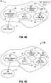
- a prior art ZigBee® wireless mesh network 30is shown.
- a typical ZigBee® networkincludes one router acting as the coordinator 31, optionally one or more other routers 32 and optionally one or more end nodes 33.
- the coordinator 31 and other router(s) 32includes the capability to act as an intermediary to relay data from source devices to destination devices. Both the coordinator 31 and router(s) are maintained in a powered-up mode, that is, neither coordinator 31 nor router 32 may go into sleep mode.
- the end node(s) 33may include functionality to perform a task (such as sensing a condition or accepting a user input).
- An end node 33communicates through a coordinator 31 or a router 32 and is called a child of that router, which is called the parent of that end node.
- a parent nodecommunicates directly with its child node(s) and relays messages between its child node(s) and other nodes in the mesh network.
- An end node 33may enter a sleep mode, and, in practice, may be in sleep mode most of the time to conserve battery life. Additionally, end nodes 33 typically include a relatively modest amount of computing resources, and therefore are typically less expensive to manufacture than a coordinator 31 or router 32.
- Prior art network 30typically operates as follows: Assume end node 33 is to send a message to destination node 32c. A message is typically formed by one or more packets containing a destination address corresponding to the destination node, and the data to be sent to the destination node. The message is sent from the end node 33 to the parent node 32a and may be relayed through one or more other router nodes until it reaches the destination. At each handoff, the receiving node transmits a low-level acknowledgement (e.g., a data link layer, or MAC acknowledgement, etc.) to the sending node to confirm receipt.
- a low-level acknowledgemente.g., a data link layer, or MAC acknowledgement, etc.
- the destination nodeWhen the message reaches the destination node, the destination node, if requested, sends a higher-level acknowledgement message, such as an APS acknowledgement (APS ack), back to the originating node.
- APS ackmay be relayed to the originating node through the same series of nodes in reverse, or may take a different route.
- the source of a messagesuch as end node 33, must determine the destination address of the destination node.
- a station tag IDwhich includes identifying information relating to the destination node is used to determine the destination address.
- the destination addressitself is not typically used as the tag ID, because network addresses are randomly assigned and may change in a ZigBee® network.
- Tagsmay include, for example, the MAC address of a wireless node, a protocol address of a ZigBee® device implementing the generic tunnel cluster, or some independent information configured by a user through a user interface, such as the settings of jumpers or rotary dial switches or via a touch screen, buttons, etc.
- end node 33wakes up to send a message containing data to, for example, router 32c.
- the address of the destination nodemust be determined by end node 33.
- End node 33queries the network to obtain the address of the destination node.
- the ZigBee® standardprovides for broadcast requests to discover a node having a specified MAC address
- the generic tunnel clusterprovides broadcast requests to match a protocol address to a node.
- An applicationcan, in general, provide for discovery of the node matching any desired tag.
- End node 33then formats the message by combining the message data with the address of the destination node (router 32c) to form one or more message packets.
- the messageis then transmitted to the parent node, which, in the present example, is router 32a.
- the receiving nodehere, router 32a
- Router 32areceives the message, examines the destination address, determines that the destination address belongs to a node other than itself, and, as seen in Fig. 3B , forwards the message to the next node. If router 32a does not have a stored route for reaching the destination node, then router 32 must discover a route before forwarding the message.
- router 32may discard the message, only forwarding messages that end node 33 sends in the future when router 32 has a stored route to the destination.
- the next nodeis coordinator 31.
- Coordinator 31repeats the process, and as shown in Fig. 3C , forwards the message to the destination node e.g., router 32c.
- the destination nodeUpon receipt, the destination node transmits an application acknowledgement message (APS ack) to the originating end node 33 via the reverse path from the original message as shown in Figs. 3D , 3E, and 3F .
- APS ackapplication acknowledgement message
- a function of APS acksis to enhance reliability.
- the ZigBee® application support layercan use APS acks to determine when to repeat sending a message so that message delivery is more reliable. Another function of APS acks is to facilitate the detection of when a destination address changes, so that the source can determine the new address for the destination.
- An end nodeuses battery power to wake up repeatedly to poll its parent node as the end node attempts to receive the APS ack for each message it sends.
- the time and power requiredmay include time and power used for route discovery and repeated transmissions.
- Each routermaintains a routing table to store the next relay for each destination to which it can forward packets in the mesh network.
- Such routing tablesare allocated a finite amount of memory and therefore can hold only up to a certain number of entries. In order to make room for new routes, stale entries which are older and/or lesser-used are purged from the table. To avoid unnecessary route discovery processes, the tables must be large enough to contain entries for addresses of data destinations and end devices (which are destinations of APS acks). These requirements are costly in terms of power consumption and computing resource usage.
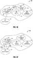
- Figs. 4A-4Fillustrate an exemplary embodiment of an energy-efficient wireless mesh network 50 that significantly extends battery life by minimizing the amount of time the end node needs to be awake, and by delegating responsibility for finding the destination address to the router.
- Embodiments of the present disclosureeliminate the need for repetitive wake/poll/sleep cycles to receive an application acknowledgement by allowing a message to be reliably dispatched from an end node using a single radio transmission, while maintaining network reliability by sending the message with APS acks to the destination.
- the network 50includes a battery-powered end node 51, router nodes 52, 53, and 54, and coordinator node 55.
- the network configuration shown in the Figs. 4A-4Fis exemplary, and it is to be understood that embodiments having other configurations, e.g., different numbers and types of nodes, links, devices, and the like, are contemplated within the scope of the present disclosure.
- Each nodeis assigned a logical node address.
- end node 51is assigned an address of A1
- routers 52, 53, and 54are assigned addresses A2, A3, and A5, respectively
- coordinator 55is assigned address A4.
- End node 51is assigned a tag of TA
- routers 52, 53, and 54are assigned tags TB, TC, and TE, respectively
- coordinator 55is assigned tag TD.
- Routers 52, 53, and 54include an address map 56, 57, 58, respectively
- coordinator 55includes address map 59.
- An address mapcomprises a source address map and a destination address map.
- end node 51initiates a message transmission to the tag corresponding to router 54.
- End node 51which is typically in sleep mode, wakes up, and transmits message 1 to its parent node, here router 52.
- router 52Upon receipt of message 1, router 52 transmits a MAC acknowledgement back to end node 51.
- the MAC acknowledgementsignifies to end node 51, at the data link layer, that message 1 has been successfully dispatched.
- end node 51returns to sleep mode.
- end node 51remains in sleep mode until its next scheduled wake-up, that is, once the brief transmission/MAC acknowledgement cycle is complete, no further expenditure of battery energy by end node 51 is required to effectuate the transmission of message 1.
- Message 1includes the tag TE of the destination node (here, router 54).
- router 52is now the recipient of message 1.
- Router 52determines from the tag whether it is the destination for the data. If the tag in message 1 matches the tag of router 52 (TB), then router 52 accepts the data for its application. Since in this example, the tag in message 1 (TE) matches the tag of router 54 (TE), router 52 will forward the data by sending message 2 with the same tag and data as message 1, and including the data source address of end node 51 (A1). Router 52 sends message 2 through the ZigBee network to the coordinator 55, preferably using APS acks.
- router 52is not able to communicate with the coordinator, such as when the coordinator is powered down, or if the network design does not give advantage to routing messages to and from the coordinator, then router 52 instead of the coordinator finds the destination and sends message 3 to the destination as described below.
- the network design in the exemplary embodimentuses many-to-one routing toward the coordinator, and source routing along the same routes outbound from the coordinator, so there is an advantage to sending messages to and from the coordinator, avoiding route discovery and routing table entries for routes between other routers.
- coordinator 55is in receipt of message 2.
- Routers 52, 53, 54, and 55include source address maps 56, 57, 58, 59, respectively, in which message source addresses and corresponding data source addresses are stored. Any router that receives message 2 stores the message source address and data source address in its source address map. Source address maps facilitate the transmission of responses, if requested, from the destination back to the source without discovering a route.
- the coordinatordetermines the destination address and sends to it message 3, which contains the same tag and data as message 1 with the data source address of end node 51, preferably using APS acks.
- Routersinclude destination address maps in maps 56 et al. in which tags and corresponding destination addresses are stored. Any router that needs to send message 3 stores the tag and data destination address in its destination address map.
- router 54Message 3 has arrived at the destination node, router 54. If the tag in message 3 does not match the tag in router 54, then router 54 will handle message 3 in the same manner as router 52 handled message 1, and the sender of message 3 will detect when it receives a message 2 from the address stored in its destination address map that the map entry is no longer valid, whereupon it will determine the new destination address and send a new message 3. Otherwise, the tag in message 3 will match the tag in the destination, here router 54, so router 54 processes the message. For example, the destination node may act upon the message in accordance with the application function to which the message is directed, e.g., record a temperature, activate or deactivate a heat pump, and so forth will be understood by one skilled in the art.
- the destination nodemay act upon the message in accordance with the application function to which the message is directed, e.g., record a temperature, activate or deactivate a heat pump, and so forth will be understood by one skilled in the art.
- the response message 4 containing the data source tag ID and the responseis transmitted to the source of message 3 or, if the data source is a child of the destination, to the data source.
- a router that has recently sent a message 3receives a response message 4, it sends a response message 5 to the message source address corresponding to the data source address in its source address map or, if the data source is a child of the router that sent message 3, to the data source.
- map 59indicates the message source corresponding to tag T1 was address A2 (router 52), therefore coordinator 53 sends response message 5 to that node ( Fig. 4E ).
- Router 52determines that it is the parent node to the data source, end node 51, so it sends the response message to the data source. Since end node 51 is a device capable of sleep mode, the parent caches the message sent to the child. When the child wakes up, the child polls the parent, and receives pending cached messages from the parent ( FIG. 4F ).
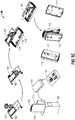
- Figs. 5A-5Dan HVAC sensor 90 assemblable in a first configuration 100 having an exposed display, shown in Figs. 5A and 5B , and second configuration 110 having a concealed display, shown in Figs. 5C and 5D , is described.
- the disclosed HVAC sensor 90utilizes a printed circuit board 102 which is utilized in both configurations, which increases economies of scale, reduces development and testing costs, and simplifies inventory control.
- Printed circuit board 102includes a display side and a non-display side, and may be mounted within sensor 90 with the display side facing inward or outward, as described in detail below.
- sensor 90includes a housing 101 having front portion 106 generally suited for facing a user, and a rear portion 107 generally suited for attaching to a mounting surface, such as a wall.
- Housing front portion 106includes a display opening 105 and one or more switch openings 119 defined therein.
- sensor 90includes a housing 111 having a having front portion 116 generally suited for facing a user, and a rear portion 117 generally suited for attaching to a mounting surface, such as a wall or column.
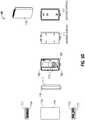
- one or more of front portion 106, front portion 116, rear portion 107, rear portion 117 and/or printed circuit board 102may be included in an installation kit which enables an installer to select on-site which configuration (visible display or hidden display) is appropriate for a particular installation location.
- rear portion 107may be substituted for rear portion 117, and therefore, only one of rear portion 107 or rear portion 117 need be included in the installation kit.
- Sensor 90includes a reversible printed circuit board 102 having a display module 103 operatively mounted thereupon.
- display module 103may include a liquid crystal display (LCD).
- LCDliquid crystal display
- e-paperelectronic paper display
- Printed circuit board 102includes a switch assembly 104 operatively coupled thereto which enables a user to interact with sensor 90, for example, to set a device identifier, to join a wireless mesh network, to activate the display, and so forth.
- Printed circuit board 102includes one or more notches 108 defined along a peripheral edge thereof that are dimensioned to effectuate snap-fit engagement with corresponding mounting tabs 118 provided by sensor housing 101 and/or sensor housing 111.
- Printed circuit board 102includes a pair of battery contacts 109 which are configured to operatively engage one or more batteries 114.
- housing 101 and 111are configured to retain the one or more batteries 114 on opposite sides for one another as required to accommodate printed circuit board 102 in its exposed display configuration 100 and in its concealed display configuration 110.
- an installermay use display module 103 and switch assembly 104 to perform initial setup of sensor 90, e.g., to set a device address, join a wireless mesh network, and so forth. This is readily performed in the exposed display configuration 100, since the display 103 and switch assembly 104 are openly accessible. With the concealed display configuration 110, the installer may separate the two halves of housing 111 to access the display 103 and/or switch assembly 104 concealed therewithin. Once the initial setup is complete, the housing is reassembled by reattaching front portion 116 and rear portion 117, and the sensor 90 may be placed into service.
- Sensor 90may be an power-efficient HVAC sensor which includes a sleep current fault detector 3, a power-efficient method 200 of operating a wireless HVAC device, and/or other power-saving features described herein.
- HVAC device 210includes switch assembly 205, a display 206, and may incorporate wireless sensor, a thermostat, and so forth.
- display 206may include a touchscreen display.
- HVAC device 210is adapted for wireless communication with one or more wireless nodes 220, 230.
- wireless nodes 220a, 220b, 230include, but are not limited to, a ZigBee® routing node (e.g., a wireless communication interface or WCI) and/or a ZigBee® coordinator node.
- HVAC device 210is typically mounted upon a wall or other surface that is easily accessible to a user. At most times, HVAC device 210 operates in a low-power sleep mode, which prolongs battery life. In some embodiments, during sleep mode display 206 may display only locally-available data items, e.g., data which does not require a network transmission to obtain. In this manner, power is further conserved by preventing the network circuitry (e.g., the 802.15.4 transceiver) from powering up during sleep mode. In some embodiments, HVAC device 210 will deactivate display 206 during sleep mode in order to further conserve power. In embodiments where HVAC device 210 includes a sensor, HVAC device 210 may periodically "wake up" into an active mode, transmit the current sensor reading, then return to sleep mode.
- the network circuitrye.g., the 802.15.4 transceiver
- HVAC device 210includes the capability of presenting data on display 206, for example, it may display the locally-sensed sensor value and/or data obtained via wireless communication from another network node. Since HVAC device 210 is, during the bulk of its lifecycle, simply mounted upon a wall and not being viewed or interacted with by a user, HVAC device 210 remains in sleep mode until a display request is expressly made by a user.
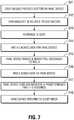
- a userinitiates a data display request in step 241, whereupon a user interacts with HVAC device 210 by actuating a pushbutton 205, which may be a single press, a double press, or a similar gesture.
- a pushbutton 205which may be a single press, a double press, or a similar gesture.
- display 206is a touchscreen display
- a usermay tap or swipe the display to initiate the request.
- a usermay enter a choice of which data items the user wishes to view. For example, a single, initial actuation may cause HVAC device 210 to proceed to display a default or preselected data item (such as system temperature setpoint).
- HVAC device 210wakes up and prepares a data request message.
- HVAC device 210transmits the data request message to the destination node, and reverts to sleep mode.
- the data request messageis relayed by the wireless network (e.g., routers 220a, 200b) to the destination node 230.
- the destination node 230transmits the requested data to HVAC device 210.
- Router 220ais most adjacent node to HVAC device 210, and so it is router 220a which has the last "hop" to HVAC device 210.
- Router 220aattempts to relay the response to HVAC device 210. Since HVAC device 210 has previously reverted to sleep mode, and is likely still in sleep mode, router 220a is temporarily unable to transmit the response to HVAC device 210. Therefore, in step 224, router 220a caches the response and begins to await a polling message from HVAC device 210.
- HVAC device 210wakes up and transmits a polling message to its network neighbor, e.g., router 220a.
- router 220atransmits the data message to HVAC device 210.
- HVAC device 210presents the requested data on display 206 for a predetermined time, for example, about 3-5 seconds, and in step 248, HVAC device 210 return to sleep mode.
Landscapes
- Engineering & Computer Science (AREA)
- Computer Networks & Wireless Communication (AREA)
- Signal Processing (AREA)
- General Engineering & Computer Science (AREA)
- Theoretical Computer Science (AREA)
- Physics & Mathematics (AREA)
- General Physics & Mathematics (AREA)
- Chemical & Material Sciences (AREA)
- Combustion & Propulsion (AREA)
- Mechanical Engineering (AREA)
- Automation & Control Theory (AREA)
- Mobile Radio Communication Systems (AREA)
Description
- The present disclosure is directed to systems, apparatus, and methods for improving wireless HVAC components, and in particular, HVAC sensors and HVAC controllers having reduced power consumption, lower manufacturing costs, and increased reliability.
- Heating, ventilation, and air conditioning systems (HVAC systems) typically utilize one or more sensors, thermostats, and/or HVAC controllers to monitor environmental conditions in a building and to operate HVAC equipment installed at the building. Prior art systems utilize components which are interconnected using traditional hard-wiring techniques using electrical conductors routed within the physical structure. Hard-wired systems are generally reliable, but the costs of cabling and installation are high. This is particularly true when installing devices in existing structures where cabling must be snaked through walls and ceilings. More recently, the use of wireless HVAC devices has become popular since installation is simple and low-cost. Existing wireless devices may have drawbacks in that the batteries used in these devices have a limited lifespan and require periodic maintenance and replacement to ensure the HVAC system continues to function reliably. Depending on various system requirements, such wireless sensors, HVAC controllers, and other wireless devices may be required to include, or not include, a user-visible panel or user interface. The need to design, test, and manufacture different versions of wireless devices increases costs and reduces profits and market advantage. A wireless HVAC device which offers reduced power consumption, lower manufacturing costs, and increased reliability would be a welcome advance in the art.
US2008/151454 discloses an electronic battery safety switch comprising a solid-state switch arranged to electrically disconnect a motor vehicle on-board network and the battery with the application of a crash signal or an overcurrent signal or when the ignition is switched off. - In one aspect, the present disclosure is directed to a method of sensing excessive sleep current draw in a battery-powered device having a microcontroller. In an embodiment, the disclosed method includes measuring a voltage drop across a MOSFET device coupled in a forward-conducting orientation in series between the battery and the microcontroller; causing a transistor to conduct when the voltage drop exceeds a predetermined threshold to generate a first trigger signal; integrating the first trigger signal to generate a second trigger signal; and generating an interrupt to the microcontroller in response to the second trigger signal. In an embodiment, the predetermined threshold is consistent with excessive current draw during sleep. In an embodiment, the method includes transmitting, from the microcontroller, a fault signal in response to the interrupt.
- In another aspect, the present disclosure is directed to a sleep current fault detection circuit for use with a powered device operable in a sleep mode and an awake mode. In an embodiment, the circuit includes a MOSFET, the drain terminal thereof coupled to a current source, the gate terminal thereof coupled to a powered device, the source terminal thereof coupled to ground; a first transistor, the emitter terminal thereof coupled to the drain terminal of the MOSFET and configured to conduct when the voltage across the drain terminal of the MOSFET and the source terminal of the MOSFET exceeds a predetermined voltage; a second transistor, the base terminal thereof coupled to the collector of the first transistor, the collector terminal thereof coupled to an R-C filter; and a third transistor, the base terminal thereof coupled to the R-C filter, the collector terminal thereof coupled to an interrupt terminal of the powered device. In an embodiment, the gate terminal of the MOSFET may be coupled to an output of the powered device. In an embodiment, the output of the powered device turns off the MOSFET prior to entering sleep mode. In an embodiment, the output of the powered device turns on the MOSFET when entering awake mode. In an embodiment, predetermined voltage may be about 0.5 volts.
- In yet another aspect, the present disclosure is directed to an energy-efficient method of transmitting data from the end node to a destination node in a mesh network having an end node operable in a sleep mode and an awake mode. The method includes transmitting a first message, the first message including a tag ID of the destination node and message data, from the end node to a parent node of the end node; receiving, at the end node, a first acknowledgement from the parent node acknowledging receipt of the first message by the parent node; causing the end node to enter sleep mode in response to the acknowledgement; determining, at the parent node, whether the parent node is the destination node; and transmitting a second message, the second message including the destination node tag, the message data, and a network address of the parent node, to the destination node in response to determination that the parent node is not the destination node.
- Various embodiments of the disclosed system and method are described herein with reference to the drawings wherein:
Fig. 1 is a block diagram of an embodiment of an improved wireless HVAC device in accordance with the present disclosure;Fig. 2 is a schematic diagram of an embodiment of a sleep current fault detection circuit in accordance with the present disclosure;Figs. 3A-3F are diagrams illustrating a prior art mesh network;Figs. 4A-4F are diagrams illustrating aspects of an energy-efficient mesh network in accordance with an embodiment of the present disclosure;Figs. 5A-5D present embodiments of a wireless HVAC device having a reversible printed circuit board and assemblable in a first configuration having an exposed display and second configuration having a hidden display; andFigs. 6 and7 illustrate a method of extending battery life in a wireless HVAC device in accordance with an embodiment of the present disclosure.- The various aspects of the present disclosure mentioned above are described in further detail with reference to the aforementioned figures and the following detailed description of exemplary embodiments.
- Particular illustrative embodiments of the present disclosure are described hereinbelow with reference to the accompanying drawings; however, the disclosed embodiments are merely examples of the disclosure, which may be embodied in various forms. Well-known functions or constructions and repetitive matter are not described in detail to avoid obscuring the present disclosure in unnecessary or redundant detail. Therefore, specific structural and functional details disclosed herein are not to be interpreted as limiting, but merely as a basis for the claims and as a representative basis for teaching one skilled in the art to variously employ the present disclosure in virtually any appropriately detailed structure. In this description, as well as in the drawings, like-referenced numbers represent elements which may perform the same, similar, or equivalent functions. The word "exemplary" is used herein to mean "serving as an example, instance, or illustration." Any embodiment described herein as "exemplary" is not necessarily to be construed as preferred or advantageous over other embodiments. The word "example" may be used interchangeably with the term "exemplary."
- The present disclosure is described herein in terms of functional block components and various processing steps. It should be appreciated that such functional blocks may be realized by any number of hardware and/or software components configured to perform the specified functions. For example, the present disclosure may employ various integrated circuit components, e.g., memory elements, processing elements, logic elements, look-up tables, and the like, which may carry out a variety of functions under the control of one or more microprocessors or other control devices.
- Similarly, the software elements of the present disclosure may be implemented with any programming or scripting language such as C, C++, C#, Java, COBOL, assembler, PERL, Python, PHP, or the like, with the various algorithms being implemented with any combination of data structures, objects, processes, routines or other programming elements. The object code created may be executed by any device, on a variety of operating systems, including without limitation RTOS, Apple OSX®, Apple iOS®, Google Android®, HP WebOS®, Linux, UNIX®, Microsoft Windows®, and/or Microsoft Windows Mobile®.
- It should be appreciated that the particular implementations described herein are illustrative of the disclosure and its best mode and are not intended to otherwise limit the scope of the present disclosure in any way. Examples are presented herein which may include data items which are intended as examples and are not to be construed as limiting. Indeed, for the sake of brevity, conventional data networking, application development and other functional aspects of the systems (and components of the individual operating components of the systems) may not be described in detail herein. It should be noted that many alternative or additional functional relationships or physical or virtual connections may be present in a practical electronic system or apparatus. In the discussion contained herein, the terms user interface element and/or button are understood to be non-limiting, and include other user interface elements such as, without limitation, pushbutton, a proximity sensor, a hyperlink, clickable image, and the like.
- As will be appreciated by one of ordinary skill in the art, the present disclosure may be embodied as a method, a data processing system, a device for data processing, and/or a computer program product. The present disclosure may take the form of a computer program product on a computer-readable storage medium having computer-readable program code means embodied in the storage medium. Any suitable computer-readable storage medium may be utilized, including hard disks, CD-ROM, DVD-ROM, optical storage devices, magnetic storage devices, semiconductor storage devices (e.g., EEPROM, mask ROM, flash memory, USB thumb drives) and/or the like.
- Computer program instructions embodying the present disclosure may also be stored in a computer-readable memory that can direct a computer or other programmable data processing apparatus to function in a particular manner, such that the instructions stored in the computer-readable memory produce an article of manufacture, including instruction means, that implement the function specified in the description or flowchart block(s). The computer program instructions may also be loaded onto a computer or other programmable data processing apparatus to cause a series of operational steps to be performed on the computer or other programmable apparatus to produce a computer-implemented process such that the instructions that execute on the computer or other programmable apparatus provide steps for implementing the functions specified in the present disclosure.
- One skilled in the art will also appreciate that, for security reasons, any components, data structures, and communications links may include any of various suitable security features, such as firewalls, access codes, encryption, de-encryption, compression, decompression, and/or the like. In some instances, the steps recited herein may be executed in any order and are not limited to the order presented.
- Exemplary embodiments are disclosed herein which operate in accordance with the ZigBee® wireless mesh networking standards, however, it should be understood that embodiments of the present disclosure are applicable to any wired or wireless network architecture, including without limitation Z-Wave®, in which the features and advantages discussed herein may be advantageously employed.
- Referring to
Fig. 1 , awireless HVAC device 1 in accordance with the present disclosure is shown.Wireless HVAC device 1 includes abattery 4 or other power source configured to provide operating power to amicrocontroller 6, anetwork interface 7, one ormore input devices 5, and/or adisplay 8.Microcontroller 6 may include a processor, and a memory operatively associated with the processor, the memory storing executable instructions, which, when executed on the processor, perform one or more of the methods described herein.Wireless HVAC device 1 includes a sleepcurrent fault detector 3 which detects excessive current draw frombattery 4 whenHVAC device 1 is in a low-power, or "sleep" mode. Sleepcurrent fault detector 3 includes sleep currentfault detection circuit 10, discussed in detail below. Display 8 may include, without limitation, an LCD display, an electronic paper display (e-paper) or any other suitable display which meets the low-power and environmental requirements for an HVAC sensor.Display 8 may be externally viewable during normal use, or may be concealed from view during normal use but visible during an initial setup task, as described below. Input device(s) 5 may include one or switches, pushbuttons, touchscreen, proximity sensor, or other input device.HVAC device 1 includes asensor 9, such as, without limitation, a temperature sensor, a humidity sensor, a barometric pressure sensor, a light sensor, a proximity sensor, and the like.Network interface 7 may include a radiofrequency (RF) transceiver that is configured to facilitate communications in accordance with the 802.15.4 standard. In embodiments,network interface 7 operates in accordance with the ZigBee® wireless communications protocol.- With reference to
Fig. 2 , a sleep currentfault detection circuit 10 is disclosed.Circuit 10 is adapted to work with adevice 11, which may include a microcontroller, radio module, or any other integrated or discrete circuit, which is operable in a normal, "awake" or "active" mode, and a low-power or "sleep" mode. Sleep currentfault detection circuit 10 is suitable for battery-powered devices that spend a significant amount of time in a low-powered (e.g., sleep) mode. While such a device is sleeping, if a fault occurs and current draw increases, battery life can be dramatically shortened. The disclosed sleep currentfault detection circuit 10 is designed to detect such failures, with negligible energy consumption. - With continued reference to
Fig. 2 , a positive terminal ofbattery 12 is coupled to Vcc. A MOSFET 13 (Q2) is coupled in series between a negative terminal ofbattery 13 andground 26.MOSFET 13 is configured such that the body diode ofMOSFET 13 is in a forward conducting state whendevice 11 is powered up e.g., the drain terminal ofMOSFET 13 is coupled to the negative terminal ofbattery 12, and the source terminal ofMOSFET 13 is coupled toground 26. Note that, because of the voltage drop across the drain and source ofMOSFET 13, the negative terminal ofbattery 12 will be at a lower potential thanground 26.Ground terminal 24 ofdevice 11 is also connected to ground 26. - In operation, before entering sleep mode,
MOSFET 13 is turned off viaGPIO output 25. Whendevice 11 awakes from sleep,MOSFET 13 is turned on viaGPIO output 25. During sleep mode, if the current consumed bydevice 11 increases, so too does the voltage drop across the drain and source ofMOSFET 13. During sleep mode withMOSFET 13 off, this voltage drop is about 0.3V. Ifdevice 11 increases current draw during sleep, the voltage drop acrossMOSFET 13 will increase. Therefore, by detecting this increase in voltage drop, the current draw ofdevice 11 is determined. If the voltage drops exceeds a predetermined limit, e.g., greater than approximately 0.5V, an interrupt is flagged to an interruptterminal 23 ofdevice 11. Advantageously,device 11 includes the capability to monitor the activity of interrupt terminal 23 while in sleep mode, and execute a task (wake up, execute an interrupt handler, etc.) in response to the sleep fault condition. In a typical scenario, the current draw ofdevice 11 may be about 2uA during sleep. A sleep current failure circuit in accordance with the present example embodiment will detect an increase in sleep current draw of one or more orders of magnitude. So, for example, a sleep current circuit in accordance with the present example embodiment will trigger at about a 20uA current draw. Other embodiments are contemplated which detect even smaller changes of current flow. In embodiments, The disclosed sleep currentfault detection circuit 10 may be configured to detect sleep current faults in other circuit elements in addition to, or alternatively to,device 11. - The emitter terminal of a transistor 14 (Q3) is coupled to the drain of
MOSFET 13. The base oftransistor 14 is coupled toground 26. During normal sleep mode, the base-emitter voltage across resistor 15 (R20), corresponding to the voltage drop acrossMOSFET 13, is low, which causestransistor 14 to remain off. If, however, a sleep fault occurs which results in excessive current draw,transistor 14 will switch on. Transistor 16 (Q4) and transistor 18 (Q5) are configured as buffered gain stages which drive an interruptterminal 23 ofdevice 11 when a sleep power fault is detected. AnR-C network 19 formed by resistor 20 (R4) and capacitor 21 (C8) delays the turn-on time oftransistor 18 to prevent false positives and other spurious or transient conditions from triggering the interrupt todevice 11. Device 11 monitors interrupt terminal 23 while in sleep mode. Whentransistor 18 turns on, interrupt terminal 23 is pulled low which causesdevice 11 to wake up and perform a desired task. For example,device 11 can display an error code, transmit to a receiver that it has a sleep current issue, power down sections of the sensor to isolate the problem, or perform any other task which may be appropriate in response to a sleep current failure.- Turning to
Figs. 3A-3F , a prior art ZigBee®wireless mesh network 30 is shown. A typical ZigBee® network includes one router acting as thecoordinator 31, optionally one or more other routers 32 and optionally one ormore end nodes 33. Thecoordinator 31 and other router(s) 32 includes the capability to act as an intermediary to relay data from source devices to destination devices. Both thecoordinator 31 and router(s) are maintained in a powered-up mode, that is, neithercoordinator 31 nor router 32 may go into sleep mode. The end node(s) 33 may include functionality to perform a task (such as sensing a condition or accepting a user input). Anend node 33 communicates through acoordinator 31 or a router 32 and is called a child of that router, which is called the parent of that end node. A parent node communicates directly with its child node(s) and relays messages between its child node(s) and other nodes in the mesh network. Anend node 33 may enter a sleep mode, and, in practice, may be in sleep mode most of the time to conserve battery life. Additionally,end nodes 33 typically include a relatively modest amount of computing resources, and therefore are typically less expensive to manufacture than acoordinator 31 or router 32. Prior art network 30 typically operates as follows: Assumeend node 33 is to send a message todestination node 32c. A message is typically formed by one or more packets containing a destination address corresponding to the destination node, and the data to be sent to the destination node. The message is sent from theend node 33 to theparent node 32a and may be relayed through one or more other router nodes until it reaches the destination. At each handoff, the receiving node transmits a low-level acknowledgement (e.g., a data link layer, or MAC acknowledgement, etc.) to the sending node to confirm receipt. When the message reaches the destination node, the destination node, if requested, sends a higher-level acknowledgement message, such as an APS acknowledgement (APS ack), back to the originating node. The APS ack may be relayed to the originating node through the same series of nodes in reverse, or may take a different route.- The source of a message, such as
end node 33, must determine the destination address of the destination node. To determine the destination address, a station tag ID which includes identifying information relating to the destination node is used to determine the destination address. The destination address itself is not typically used as the tag ID, because network addresses are randomly assigned and may change in a ZigBee® network. Tags may include, for example, the MAC address of a wireless node, a protocol address of a ZigBee® device implementing the generic tunnel cluster, or some independent information configured by a user through a user interface, such as the settings of jumpers or rotary dial switches or via a touch screen, buttons, etc. - As seen in
Fig. 3A ,end node 33 wakes up to send a message containing data to, for example,router 32c. Before sending the message the first time to a destination, the address of the destination node must be determined byend node 33.End node 33 queries the network to obtain the address of the destination node. For example, the ZigBee® standard provides for broadcast requests to discover a node having a specified MAC address, and the generic tunnel cluster provides broadcast requests to match a protocol address to a node. An application can, in general, provide for discovery of the node matching any desired tag.End node 33 then formats the message by combining the message data with the address of the destination node (router 32c) to form one or more message packets. The message is then transmitted to the parent node, which, in the present example, isrouter 32a. The receiving node (here,router 32a) will transmit a MAC acknowledgement to the transmitting node (here, end node 33) to confirm receipt of the transmitted packet at the data link level.Router 32a receives the message, examines the destination address, determines that the destination address belongs to a node other than itself, and, as seen inFig. 3B , forwards the message to the next node. Ifrouter 32a does not have a stored route for reaching the destination node, then router 32 must discover a route before forwarding the message. In some instances, router 32 may discard the message, only forwarding messages that endnode 33 sends in the future when router 32 has a stored route to the destination. Continuing with the present example, the next node iscoordinator 31.Coordinator 31 repeats the process, and as shown inFig. 3C , forwards the message to the destination node e.g.,router 32c. Upon receipt, the destination node transmits an application acknowledgement message (APS ack) to the originatingend node 33 via the reverse path from the original message as shown inFigs. 3D ,3E, and 3F . A function of APS acks is to enhance reliability. Since any one relay has a probability of failing, based on the wireless link quality, and the overall probability of failure to deliver the message to the destination is the probability that any one relay fails, the ZigBee® application support layer can use APS acks to determine when to repeat sending a message so that message delivery is more reliable. Another function of APS acks is to facilitate the detection of when a destination address changes, so that the source can determine the new address for the destination. - Several drawbacks exist in such prior art networks. An end node uses battery power to wake up repeatedly to poll its parent node as the end node attempts to receive the APS ack for each message it sends. The time and power required may include time and power used for route discovery and repeated transmissions. Each router maintains a routing table to store the next relay for each destination to which it can forward packets in the mesh network. Such routing tables are allocated a finite amount of memory and therefore can hold only up to a certain number of entries. In order to make room for new routes, stale entries which are older and/or lesser-used are purged from the table. To avoid unnecessary route discovery processes, the tables must be large enough to contain entries for addresses of data destinations and end devices (which are destinations of APS acks). These requirements are costly in terms of power consumption and computing resource usage.
Figs. 4A-4F illustrate an exemplary embodiment of an energy-efficientwireless mesh network 50 that significantly extends battery life by minimizing the amount of time the end node needs to be awake, and by delegating responsibility for finding the destination address to the router. Embodiments of the present disclosure eliminate the need for repetitive wake/poll/sleep cycles to receive an application acknowledgement by allowing a message to be reliably dispatched from an end node using a single radio transmission, while maintaining network reliability by sending the message with APS acks to the destination.- With reference to
Fig. 4A , thenetwork 50 includes a battery-poweredend node 51,router nodes coordinator node 55. The network configuration shown in theFigs. 4A-4F is exemplary, and it is to be understood that embodiments having other configurations, e.g., different numbers and types of nodes, links, devices, and the like, are contemplated within the scope of the present disclosure. Each node is assigned a logical node address. In the present embodiment,end node 51 is assigned an address of A1,routers coordinator 55 is assigned address A4.End node 51 is assigned a tag of TA,routers coordinator 55 is assigned tag TD.Routers address map coordinator 55 includesaddress map 59. An address map comprises a source address map and a destination address map. - As illustrated in
Fig. 4A ,end node 51 initiates a message transmission to the tag corresponding torouter 54.End node 51, which is typically in sleep mode, wakes up, and transmitsmessage 1 to its parent node, hererouter 52. Upon receipt ofmessage 1,router 52 transmits a MAC acknowledgement back to endnode 51. The MAC acknowledgement signifies to endnode 51, at the data link layer, thatmessage 1 has been successfully dispatched. In response,end node 51 returns to sleep mode. Advantageously,end node 51 remains in sleep mode until its next scheduled wake-up, that is, once the brief transmission/MAC acknowledgement cycle is complete, no further expenditure of battery energy byend node 51 is required to effectuate the transmission ofmessage 1.Message 1 includes the tag TE of the destination node (here, router 54). - As illustrated in
Fig. 4B ,router 52 is now the recipient ofmessage 1.Router 52 determines from the tag whether it is the destination for the data. If the tag inmessage 1 matches the tag of router 52 (TB), thenrouter 52 accepts the data for its application. Since in this example, the tag in message 1 (TE) matches the tag of router 54 (TE),router 52 will forward the data by sendingmessage 2 with the same tag and data asmessage 1, and including the data source address of end node 51 (A1).Router 52 sendsmessage 2 through the ZigBee network to thecoordinator 55, preferably using APS acks. Ifrouter 52 is not able to communicate with the coordinator, such as when the coordinator is powered down, or if the network design does not give advantage to routing messages to and from the coordinator, thenrouter 52 instead of the coordinator finds the destination and sendsmessage 3 to the destination as described below. The network design in the exemplary embodiment uses many-to-one routing toward the coordinator, and source routing along the same routes outbound from the coordinator, so there is an advantage to sending messages to and from the coordinator, avoiding route discovery and routing table entries for routes between other routers. - In
Fig. 4C ,coordinator 55 is in receipt ofmessage 2.Routers message 2 stores the message source address and data source address in its source address map. Source address maps facilitate the transmission of responses, if requested, from the destination back to the source without discovering a route. The coordinator determines the destination address and sends to itmessage 3, which contains the same tag and data asmessage 1 with the data source address ofend node 51, preferably using APS acks. Routers include destination address maps inmaps 56 et al. in which tags and corresponding destination addresses are stored. Any router that needs to sendmessage 3 stores the tag and data destination address in its destination address map. Message 3 has arrived at the destination node,router 54. If the tag inmessage 3 does not match the tag inrouter 54, thenrouter 54 will handlemessage 3 in the same manner asrouter 52 handledmessage 1, and the sender ofmessage 3 will detect when it receives amessage 2 from the address stored in its destination address map that the map entry is no longer valid, whereupon it will determine the new destination address and send anew message 3. Otherwise, the tag inmessage 3 will match the tag in the destination, hererouter 54, sorouter 54 processes the message. For example, the destination node may act upon the message in accordance with the application function to which the message is directed, e.g., record a temperature, activate or deactivate a heat pump, and so forth will be understood by one skilled in the art. If a response was requested by the originating node, then as shown inFig. 4D , theresponse message 4 containing the data source tag ID and the response is transmitted to the source ofmessage 3 or, if the data source is a child of the destination, to the data source. When a router that has recently sent amessage 3 receives aresponse message 4, it sends aresponse message 5 to the message source address corresponding to the data source address in its source address map or, if the data source is a child of the router that sentmessage 3, to the data source. In this case,map 59 indicates the message source corresponding to tag T1 was address A2 (router 52), thereforecoordinator 53 sendsresponse message 5 to that node (Fig. 4E ).- The response arrives at
router 52.Router 52 determines that it is the parent node to the data source,end node 51, so it sends the response message to the data source. Sinceend node 51 is a device capable of sleep mode, the parent caches the message sent to the child. When the child wakes up, the child polls the parent, and receives pending cached messages from the parent (FIG. 4F ). - Turning now to
Figs. 5A-5D , anHVAC sensor 90 assemblable in afirst configuration 100 having an exposed display, shown inFigs. 5A and5B , andsecond configuration 110 having a concealed display, shown inFigs. 5C and5D , is described. Advantageously, the disclosedHVAC sensor 90 utilizes a printedcircuit board 102 which is utilized in both configurations, which increases economies of scale, reduces development and testing costs, and simplifies inventory control. Printedcircuit board 102 includes a display side and a non-display side, and may be mounted withinsensor 90 with the display side facing inward or outward, as described in detail below. - In the first, visible-
display configuration 100 seen inFigs. 5A and5B ,sensor 90 includes ahousing 101 havingfront portion 106 generally suited for facing a user, and arear portion 107 generally suited for attaching to a mounting surface, such as a wall. Housingfront portion 106 includes adisplay opening 105 and one ormore switch openings 119 defined therein. In the second, concealed-display configuration 110 shown inFigs. 5C and5D ,sensor 90 includes ahousing 111 having a havingfront portion 116 generally suited for facing a user, and arear portion 117 generally suited for attaching to a mounting surface, such as a wall or column. In embodiments, one or more offront portion 106,front portion 116,rear portion 107,rear portion 117 and/or printedcircuit board 102 may be included in an installation kit which enables an installer to select on-site which configuration (visible display or hidden display) is appropriate for a particular installation location. In some embodiments,rear portion 107 may be substituted forrear portion 117, and therefore, only one ofrear portion 107 orrear portion 117 need be included in the installation kit. Sensor 90 includes a reversible printedcircuit board 102 having adisplay module 103 operatively mounted thereupon. In embodiments,display module 103 may include a liquid crystal display (LCD). Alternatively, an electronic paper display (e-paper) or any other suitable display which meets the low-power and environmental requirements for an HVAC sensor may be utilized, as will be appreciated by the skilled artisan. Printedcircuit board 102 includes aswitch assembly 104 operatively coupled thereto which enables a user to interact withsensor 90, for example, to set a device identifier, to join a wireless mesh network, to activate the display, and so forth. Printedcircuit board 102 includes one ormore notches 108 defined along a peripheral edge thereof that are dimensioned to effectuate snap-fit engagement with corresponding mountingtabs 118 provided bysensor housing 101 and/orsensor housing 111. Printedcircuit board 102 includes a pair ofbattery contacts 109 which are configured to operatively engage one ormore batteries 114. As best seen inFigs. 5B and5D ,housing more batteries 114 on opposite sides for one another as required to accommodate printedcircuit board 102 in its exposeddisplay configuration 100 and in itsconcealed display configuration 110.- In use, an installer may use
display module 103 and switchassembly 104 to perform initial setup ofsensor 90, e.g., to set a device address, join a wireless mesh network, and so forth. This is readily performed in the exposeddisplay configuration 100, since thedisplay 103 and switchassembly 104 are openly accessible. With the concealeddisplay configuration 110, the installer may separate the two halves ofhousing 111 to access thedisplay 103 and/or switchassembly 104 concealed therewithin. Once the initial setup is complete, the housing is reassembled by reattachingfront portion 116 andrear portion 117, and thesensor 90 may be placed into service.Sensor 90 may be an power-efficient HVAC sensor which includes a sleepcurrent fault detector 3, a power-efficient method 200 of operating a wireless HVAC device, and/or other power-saving features described herein. - Turning to
Figs. 6 and7 , a power-efficient method 200 of operating awireless HVAC device 210 is shown.HVAC device 210 includesswitch assembly 205, adisplay 206, and may incorporate wireless sensor, a thermostat, and so forth. In embodiments,display 206 may include a touchscreen display.HVAC device 210 is adapted for wireless communication with one or morewireless nodes 220, 230. As shown,wireless nodes HVAC device 210 is typically mounted upon a wall or other surface that is easily accessible to a user. At most times,HVAC device 210 operates in a low-power sleep mode, which prolongs battery life. In some embodiments, duringsleep mode display 206 may display only locally-available data items, e.g., data which does not require a network transmission to obtain. In this manner, power is further conserved by preventing the network circuitry (e.g., the 802.15.4 transceiver) from powering up during sleep mode. In some embodiments,HVAC device 210 will deactivatedisplay 206 during sleep mode in order to further conserve power. In embodiments whereHVAC device 210 includes a sensor,HVAC device 210 may periodically "wake up" into an active mode, transmit the current sensor reading, then return to sleep mode.HVAC device 210 includes the capability of presenting data ondisplay 206, for example, it may display the locally-sensed sensor value and/or data obtained via wireless communication from another network node. SinceHVAC device 210 is, during the bulk of its lifecycle, simply mounted upon a wall and not being viewed or interacted with by a user,HVAC device 210 remains in sleep mode until a display request is expressly made by a user.- In more detail, a user initiates a data display request in
step 241, whereupon a user interacts withHVAC device 210 by actuating apushbutton 205, which may be a single press, a double press, or a similar gesture. In embodiments wheredisplay 206 is a touchscreen display, a user may tap or swipe the display to initiate the request. Additionally or alternatively, a user may enter a choice of which data items the user wishes to view. For example, a single, initial actuation may causeHVAC device 210 to proceed to display a default or preselected data item (such as system temperature setpoint). Additional actuations, for example, which navigate through a series of user interface selections, menus, etc., may allow the user to select alternative data items, groups of items, and so forth. Upon user actuation,HVAC device 210 wakes up and prepares a data request message. - In
step 242,HVAC device 210 transmits the data request message to the destination node, and reverts to sleep mode. The data request message is relayed by the wireless network (e.g.,routers 220a, 200b) to thedestination node 230. Instep 243, thedestination node 230 transmits the requested data toHVAC device 210.Router 220a is most adjacent node toHVAC device 210, and so it isrouter 220a which has the last "hop" toHVAC device 210.Router 220a attempts to relay the response toHVAC device 210. SinceHVAC device 210 has previously reverted to sleep mode, and is likely still in sleep mode,router 220a is temporarily unable to transmit the response toHVAC device 210. Therefore, in step 224,router 220a caches the response and begins to await a polling message fromHVAC device 210. - In
step 245HVAC device 210 wakes up and transmits a polling message to its network neighbor, e.g.,router 220a. In response, instep 246router 220a transmits the data message toHVAC device 210. In turn, instep 247HVAC device 210 presents the requested data ondisplay 206 for a predetermined time, for example, about 3-5 seconds, and instep 248,HVAC device 210 return to sleep mode. By seeking to keepHVAC device 210 in sleep mode and avoiding network transmissions for as long as possible, in a reliable manner, and without impacting the user experience, the disclosed methods provide extended battery life in wireless HVAC devices. - Particular embodiments of the present disclosure have been described herein, however, it is to be understood that the disclosed embodiments are merely examples of the disclosure, which may be embodied in various forms. Well-known functions or constructions are not described in detail to avoid obscuring the present disclosure in unnecessary detail. Therefore, specific structural and functional details disclosed herein are not to be interpreted as limiting, but merely as a basis for the claims and as a representative basis for teaching one skilled in the art to variously employ the present disclosure in any appropriately detailed structure.
Claims (14)
- A method of sensing excessive sleep current draw in a battery-powered device (11) having a microcontroller, the method comprising:measuring a voltage drop across a device (13) coupled in series between the battery (12) and the microcontroller;causing a transistor (14) to conduct when the voltage drop exceeds a predetermined threshold to generate a first trigger signal;integrating the first trigger signal to generate a second trigger signal; andgenerating an interrupt to the microcontroller in response to the second trigger signal.
- The method in accordance with claim 1, wherein the predetermined threshold is consistent with excessive current draw during sleep.
- The method in accordance with claim 1 or 2, further comprising transmitting, from the microcontroller, a fault signal in response to the interrupt.
- A sleep current fault detection circuit (10) configured to sense excessive sleep current draw in a battery-powered device (11) having a microcontroller, comprising:a MOSFET (13), the drain terminal thereof coupled to the battery (12), the gate terminal thereof coupled to the battery-powered device, the source terminal thereof coupled to ground (26);a first transistor (14), the emitter terminal thereof coupled to the drain terminal of the MOSFET and configured to conduct when the voltage across the drain terminal of the MOSFET and the source terminal of the MOSFET exceeds a predetermined voltage;a second transistor, the base terminal thereof coupled to the collector of the first transistor, the collector terminal thereof coupled to an R-C filter; anda third transistor, the base terminal thereof coupled to the R-C filter, the collector terminal thereof coupled to an interrupt terminal (23) of the battery-powered device.
- The circuit in accordance with claim 4, wherein the gate terminal of the MOSFET (13) is coupled to an output of the battery-powered device (11).
- The circuit in accordance with claim 5, wherein the output of the battery-powered device (11) turns off the MOSFET (13) prior to entering sleep mode.
- The circuit in accordance with claim 5 or 6, wherein the output of the battery-powered device (11) turns on the MOSFET (13) when entering awake mode.
- The circuit in accordance with any of claims 4-7, wherein the predetermined voltage is about 0.5 volts.
- A wireless HVAC device (1), comprising:a microcontroller capable of operating in a full-power mode and a low-power mode;a wireless network interface (7);an input device (5);a battery (12) having a positive and a negative terminal, wherein the battery is configured to provide operating power to the microcontroller, the wireless network interface, and the input device; anda sleep current fault detector configured to detect excessive current draw from the battery when the microcontroller is operating in a low-power mode, comprising the sleep current fault detection circuit (10) of claim 4.
- The wireless HVAC device (1) in accordance with claim 9, wherein the buffered gain stage comprises an R-C network (19) configured to delay a sleep power fault indication to prevent false positives from triggering the interrupt terminal (23) of the microcontroller.
- The wireless HVAC device (1) in accordance with claim 9 or 10, further comprising a display, wherein the battery (12) is further configured to provide operating power to the display.
- The wireless HVAC device (1) in accordance with claim 11, wherein the microcontroller, in response to a sleep power fault indication, causes a sleep power fault message to be presented on the display.
- The wireless HVAC device (1) in accordance with any of claims 9-12, wherein the microcontroller, in response to a sleep power fault indication, causes a sleep power fault message to be transmitted.
- The wireless HVAC device (1) in accordance with any of claims 9-13, wherein the microcontroller, in response to a sleep power fault indication, causes a section of the HVAC device to power down to isolate the cause of the sleep power fault indication.
Applications Claiming Priority (4)
| Application Number | Priority Date | Filing Date | Title |
|---|---|---|---|
| US201562102968P | 2015-01-13 | 2015-01-13 | |
| US201562107074P | 2015-01-23 | 2015-01-23 | |
| PCT/US2016/013234WO2016115241A1 (en) | 2015-01-13 | 2016-01-13 | Improved wireless hvac components |
| EP16737810.8AEP3245696B1 (en) | 2015-01-13 | 2016-01-13 | Improved wireless hvac components |
Related Parent Applications (2)
| Application Number | Title | Priority Date | Filing Date |
|---|---|---|---|
| EP16737810.8ADivisionEP3245696B1 (en) | 2015-01-13 | 2016-01-13 | Improved wireless hvac components |
| EP16737810.8ADivision-IntoEP3245696B1 (en) | 2015-01-13 | 2016-01-13 | Improved wireless hvac components |
Publications (2)
| Publication Number | Publication Date |
|---|---|
| EP3285348A1 EP3285348A1 (en) | 2018-02-21 |
| EP3285348B1true EP3285348B1 (en) | 2020-06-03 |
Family
ID=56406334
Family Applications (2)
| Application Number | Title | Priority Date | Filing Date |
|---|---|---|---|
| EP17183956.6AActiveEP3285348B1 (en) | 2015-01-13 | 2016-01-13 | Sleep current failure detection |
| EP16737810.8AActiveEP3245696B1 (en) | 2015-01-13 | 2016-01-13 | Improved wireless hvac components |
Family Applications After (1)
| Application Number | Title | Priority Date | Filing Date |
|---|---|---|---|
| EP16737810.8AActiveEP3245696B1 (en) | 2015-01-13 | 2016-01-13 | Improved wireless hvac components |
Country Status (4)
| Country | Link |
|---|---|
| US (6) | US10560894B2 (en) |
| EP (2) | EP3285348B1 (en) |
| CN (2) | CN107408809B (en) |
| WO (1) | WO2016115241A1 (en) |
Families Citing this family (9)
| Publication number | Priority date | Publication date | Assignee | Title |
|---|---|---|---|---|
| EP3285348B1 (en)* | 2015-01-13 | 2020-06-03 | Trane International Inc. | Sleep current failure detection |
| US10548085B2 (en)* | 2016-11-10 | 2020-01-28 | Landis+Gyr Innovations, Inc. | Optimization of broadcast messaging for low-energy devices communicating with a node on a time-slotted channel hopping network |
| KR102300791B1 (en)* | 2017-03-20 | 2021-09-09 | 엘지전자 주식회사 | Air-conditioner and method for controlling the same |
| US10772097B2 (en) | 2018-01-15 | 2020-09-08 | Trane International Inc. | Configuring an HVAC wireless communication device |
| CN112262417B (en)* | 2018-06-14 | 2022-09-20 | 住友电气工业株式会社 | Wireless sensor system, wireless terminal device, communication control method and communication control program |
| CN109561493B (en)* | 2019-01-21 | 2021-11-30 | 上海鸿研物流技术有限公司 | Terminal and awakening method thereof, and data reporting method and system of logistics system |
| US11350526B2 (en) | 2019-09-27 | 2022-05-31 | Ge Aviation Systems, Llc | Reversible electronic card and method of implementation thereof |
| CN111832424B (en)* | 2020-06-22 | 2023-10-03 | 淮阴工学院 | Multi-mode fault detection method for filter capacitor of switching power supply |
| CN112285478B (en)* | 2020-11-25 | 2024-03-19 | 北京车和家信息技术有限公司 | Method and device for detecting vehicle static current, medium, equipment and vehicle |
Family Cites Families (102)
| Publication number | Priority date | Publication date | Assignee | Title |
|---|---|---|---|---|
| FR2609552B1 (en)* | 1987-01-09 | 1990-11-30 | Merlin Gerin | CIRCUIT FOR MEASURING THE CONTINUOUS COMPONENT OF THE CURRENT THROUGH THE PRIMARY WINDING OF THE OUTPUT TRANSFORMER OF AN INVERTER |
| US5657317A (en) | 1990-01-18 | 1997-08-12 | Norand Corporation | Hierarchical communication system using premises, peripheral and vehicular local area networking |
| US4969508A (en) | 1990-01-25 | 1990-11-13 | United Enertech Corporation | Wireless thermostat and room environment control system |
| US5502610A (en)* | 1993-09-02 | 1996-03-26 | Micrel, Inc. | Switching regulator having high current prevention features |
| KR0141217B1 (en)* | 1993-11-30 | 1998-06-15 | 김광호 | Standby power saving circuit |
| US6043965A (en)* | 1997-11-20 | 2000-03-28 | General Motors Corporation | Low loss reverse battery protection |
| WO2001001366A2 (en) | 1999-06-25 | 2001-01-04 | Telemonitor, Inc. | Smart remote monitoring system and method |
| US6997740B2 (en)* | 1999-07-26 | 2006-02-14 | Angelo Fan Brace Licensing, Llc | Ceiling fixture with easy installation features |
| US6585911B2 (en) | 2000-04-20 | 2003-07-01 | Osram Sylvania Inc. | Method of making a borate phosphor having a discrete particle morphology |
| US6741066B1 (en)* | 2000-09-21 | 2004-05-25 | O2Micro International Limited | Power management for battery powered appliances |
| US6479962B2 (en)* | 2001-03-16 | 2002-11-12 | Hewlett-Packard Company | In-device charging system and method for multi-chemistry battery systems |
| US6586911B1 (en)* | 2002-02-06 | 2003-07-01 | National Semiconductor Corporation | Sleep mode power management |
| US7701858B2 (en)* | 2003-07-17 | 2010-04-20 | Sensicast Systems | Method and apparatus for wireless communication in a mesh network |
| US7806932B2 (en)* | 2003-08-01 | 2010-10-05 | Zimmer Spine, Inc. | Spinal implant |
| US7085595B2 (en)* | 2003-12-16 | 2006-08-01 | Intel Corporation | Power saving in a wireless local area network |
| US7623028B2 (en) | 2004-05-27 | 2009-11-24 | Lawrence Kates | System and method for high-sensitivity sensor |
| ES2295729T3 (en)* | 2004-05-28 | 2008-04-16 | Catem Develec Gmbh | ELECTRONIC SWITCH FOR BATTERY PROTECTION. |
| US7521896B2 (en)* | 2004-07-20 | 2009-04-21 | Panasonic Ev Energy Co., Ltd. | Abnormal voltage detector apparatus for detecting voltage abnormality in assembled battery |
| US20100081375A1 (en) | 2008-09-30 | 2010-04-01 | Apple Inc. | System and method for simplified control of electronic devices |
| US20060265489A1 (en) | 2005-02-01 | 2006-11-23 | Moore James F | Disaster management using an enhanced syndication platform |
| US8347088B2 (en) | 2005-02-01 | 2013-01-01 | Newsilike Media Group, Inc | Security systems and methods for use with structured and unstructured data |
| US20130104251A1 (en) | 2005-02-01 | 2013-04-25 | Newsilike Media Group, Inc. | Security systems and methods for use with structured and unstructured data |
| US8200700B2 (en) | 2005-02-01 | 2012-06-12 | Newsilike Media Group, Inc | Systems and methods for use of structured and unstructured distributed data |
| US7620024B2 (en)* | 2005-03-09 | 2009-11-17 | Research In Motion Limited | Hysteresis reset for an always-on mobile station |
| US7724766B2 (en)* | 2005-03-31 | 2010-05-25 | Siemens Aktiengesellschaft | High-density wireless local area network |
| US7848765B2 (en) | 2005-05-27 | 2010-12-07 | Where, Inc. | Location-based services |
| US20080259961A1 (en)* | 2005-05-30 | 2008-10-23 | Henning Wiemann | Data Unit Relay Device and Method of Controlling the Same |
| US7862944B2 (en)* | 2005-07-13 | 2011-01-04 | Gm Global Technology Operations, Inc. | Method for detection and diagnosis of isolation faults in fuel cell hybrid vehicles |
| US7536568B2 (en)* | 2005-12-01 | 2009-05-19 | Covidien Ag | Ultra low power wake-up circuit |
| EP1987582A4 (en)* | 2006-02-14 | 2018-01-24 | Flextronics Ap, Llc | Two terminals quasi resonant tank circuit |
| US20070241203A1 (en) | 2006-04-14 | 2007-10-18 | Ranco Inc. Of Delaware | Management of a thermostat's power consumption |
| US8102799B2 (en) | 2006-10-16 | 2012-01-24 | Assa Abloy Hospitality, Inc. | Centralized wireless network for multi-room large properties |
| US7826906B2 (en) | 2006-11-01 | 2010-11-02 | Intel Corporation | Transducer access point |
| US20080183307A1 (en) | 2007-01-26 | 2008-07-31 | Autani Corporation | Upgradeable Automation Devices, Systems, Architectures, and Methods |
| US8332819B2 (en) | 2007-05-03 | 2012-12-11 | Siemens Industry, Inc. | Diagnostic and trouble-shooting methods in a wireless control and sensor network |
| US7808223B1 (en)* | 2007-05-08 | 2010-10-05 | Netlogic Microsystems, Inc. | Transistor with spatially integrated schottky diode |
| US8249731B2 (en) | 2007-05-24 | 2012-08-21 | Alexander Bach Tran | Smart air ventilation system |
| US8199005B2 (en) | 2007-11-06 | 2012-06-12 | Honeywell International Inc. | System and methods for using a wireless sensor in conjunction with a host controller |
| US8224282B2 (en) | 2008-03-19 | 2012-07-17 | Siemens Industry, Inc. | Method and device to manage power of wireless multi-sensor devices |
| US20100051692A1 (en)* | 2008-09-04 | 2010-03-04 | 3M Innovative Properties Company | Detection and tracking of environmental parameters |
| US8677342B1 (en) | 2008-10-17 | 2014-03-18 | Honeywell International Inc. | System, method and apparatus for replacing wireless devices in a system |
| US8049250B2 (en)* | 2008-10-27 | 2011-11-01 | Taiwan Semiconductor Manufacturing Company, Ltd. | Circuit and method for power clamp triggered dual SCR ESD protection |
| WO2010070676A2 (en)* | 2008-12-08 | 2010-06-24 | Tycka Design Private Limited | Intuitive electronic circuit |
| US8393550B2 (en) | 2009-01-30 | 2013-03-12 | Tim Simon, Inc. | Thermostat assembly with removable communication module and method |
| EP2425223A4 (en)* | 2009-04-30 | 2017-01-25 | Underground Systems, Inc. | Overhead power line monitor |
| US20100298957A1 (en) | 2009-05-15 | 2010-11-25 | Synergy Elements, Inc. | Multi-function sensor for home automation |
| US8405333B2 (en)* | 2009-05-15 | 2013-03-26 | Texas Instruments Incorporated | Active pull-up system |
| JP5507216B2 (en)* | 2009-11-20 | 2014-05-28 | ルネサスエレクトロニクス株式会社 | Semiconductor device and power supply device |
| CN102034128B (en)* | 2009-12-31 | 2012-08-08 | 华南理工大学 | Active temporary speed-limit tag and signal processing method thereof |
| CN102214846A (en)* | 2010-04-09 | 2011-10-12 | 欣旺达电子股份有限公司 | Method for reducing consumption of battery management system and low-consumption battery management system |
| US8558583B2 (en)* | 2010-04-12 | 2013-10-15 | Texas Instruments Incorporated | Slew detection for high voltage isolation region |
| US8586925B2 (en) | 2010-06-03 | 2013-11-19 | Jeremy P. Willden | Ultra-low-power occupancy sensor |
| WO2011160694A1 (en) | 2010-06-24 | 2011-12-29 | Abb Research Ltd | A method in a wireless process control system for reducing power consumption, and a controller and computer program products |
| US20120031984A1 (en) | 2010-08-03 | 2012-02-09 | Massachusetts Institute Of Technology | Personalized Building Comfort Control |
| US9104211B2 (en) | 2010-11-19 | 2015-08-11 | Google Inc. | Temperature controller with model-based time to target calculation and display |
| US8195313B1 (en) | 2010-11-19 | 2012-06-05 | Nest Labs, Inc. | Thermostat user interface |
| US9448567B2 (en) | 2010-11-19 | 2016-09-20 | Google Inc. | Power management in single circuit HVAC systems and in multiple circuit HVAC systems |
| US9268344B2 (en) | 2010-11-19 | 2016-02-23 | Google Inc. | Installation of thermostat powered by rechargeable battery |
| US8788103B2 (en) | 2011-02-24 | 2014-07-22 | Nest Labs, Inc. | Power management in energy buffered building control unit |
| US9046898B2 (en)* | 2011-02-24 | 2015-06-02 | Google Inc. | Power-preserving communications architecture with long-polling persistent cloud channel for wireless network-connected thermostat |
| JP5744509B2 (en)* | 2010-12-28 | 2015-07-08 | 株式会社マキタ | Battery for power tools |
| US9417637B2 (en) | 2010-12-31 | 2016-08-16 | Google Inc. | Background schedule simulations in an intelligent, network-connected thermostat |
| WO2012092622A2 (en) | 2010-12-31 | 2012-07-05 | Nest Labs, Inc. | Inhibiting deleterious control coupling in an enclosure having multiple hvac regions |
| CN107065961B (en) | 2010-12-31 | 2020-06-16 | 谷歌有限责任公司 | Flexible functional partitioning of intelligent thermostat controlled HVAC systems |
| US8532008B2 (en) | 2011-01-03 | 2013-09-10 | Arnab Das | Systems, devices, and methods of managing power consumption in wireless sensor networks |
| US8511577B2 (en) | 2011-02-24 | 2013-08-20 | Nest Labs, Inc. | Thermostat with power stealing delay interval at transitions between power stealing states |
| US8742901B2 (en) | 2011-02-28 | 2014-06-03 | Conexant Systems, Inc. | Multi-sample reading in sleep mode for passive infrared detectors and other analog inputs |
| US9077183B2 (en) | 2011-09-06 | 2015-07-07 | Portland State University | Distributed low-power wireless monitoring |
| CN102394493A (en)* | 2011-09-16 | 2012-03-28 | 福建俊豪电子有限公司 | Electrical signal collection monitoring device |
| US8792492B2 (en)* | 2011-10-17 | 2014-07-29 | Telcordia Technologies, Inc. | Open communication method in a heterogeneous network |
| JP6121431B2 (en) | 2011-10-21 | 2017-04-26 | グーグル インコーポレイテッド | Automatic control schedule acquisition in the intelligent controller |
| CA3044757C (en) | 2011-10-21 | 2021-11-09 | Google Llc | User-friendly, network connected learning thermostat and related systems and methods |
| US9838652B2 (en) | 2011-11-14 | 2017-12-05 | Tseng-Lu Chien | Light device has built-in digital data system for record image, sound |
| US8890766B2 (en)* | 2011-12-01 | 2014-11-18 | Sony Corporation | Low profile multi-band antennas and related wireless communications devices |
| KR101908637B1 (en)* | 2012-01-05 | 2018-10-17 | 에스케이이노베이션 주식회사 | Circuit for measuring insulatioin resistance |
| US20130201316A1 (en) | 2012-01-09 | 2013-08-08 | May Patents Ltd. | System and method for server based control |
| US9082296B2 (en) | 2012-03-21 | 2015-07-14 | Invensys Systems, Inc. | Wireless device pairing recovery |
| US9098096B2 (en) | 2012-04-05 | 2015-08-04 | Google Inc. | Continuous intelligent-control-system update using information requests directed to user devices |
| US8972065B2 (en) | 2012-04-05 | 2015-03-03 | Google Inc. | Distribution of call-home events over time to ameliorate high communications and computation peaks in intelligent control system |
| US9582072B2 (en) | 2013-09-17 | 2017-02-28 | Medibotics Llc | Motion recognition clothing [TM] with flexible electromagnetic, light, or sonic energy pathways |
| US9292021B2 (en)* | 2012-07-18 | 2016-03-22 | Emerson Electric Co. | Line communication with twinned HVAC units |
| US9231399B2 (en)* | 2012-08-22 | 2016-01-05 | Raycap Intellectual Property Ltd. | Devices and methods for overvoltage protection |
| CN102892193B (en)* | 2012-09-20 | 2016-03-30 | 华为技术有限公司 | Data transmission method and equipment |
| US9046414B2 (en) | 2012-09-21 | 2015-06-02 | Google Inc. | Selectable lens button for a hazard detector and method therefor |
| US8994540B2 (en) | 2012-09-21 | 2015-03-31 | Google Inc. | Cover plate for a hazard detector having improved air flow and other characteristics |
| US8659302B1 (en) | 2012-09-21 | 2014-02-25 | Nest Labs, Inc. | Monitoring and recoverable protection of thermostat switching circuitry |
| US9520252B2 (en) | 2012-09-21 | 2016-12-13 | Google Inc. | Adaptable hazard detector mounting plate |
| US9007222B2 (en) | 2012-09-21 | 2015-04-14 | Google Inc. | Detector unit and sensing chamber therefor |
| US8600561B1 (en) | 2012-09-30 | 2013-12-03 | Nest Labs, Inc. | Radiant heating controls and methods for an environmental control system |
| US8554376B1 (en) | 2012-09-30 | 2013-10-08 | Nest Labs, Inc | Intelligent controller for an environmental control system |
| US8630741B1 (en) | 2012-09-30 | 2014-01-14 | Nest Labs, Inc. | Automated presence detection and presence-related control within an intelligent controller |
| US8630742B1 (en) | 2012-09-30 | 2014-01-14 | Nest Labs, Inc. | Preconditioning controls and methods for an environmental control system |
| US9696735B2 (en) | 2013-04-26 | 2017-07-04 | Google Inc. | Context adaptive cool-to-dry feature for HVAC controller |
| US9191209B2 (en) | 2013-06-25 | 2015-11-17 | Google Inc. | Efficient communication for devices of a home network |
| WO2015005677A1 (en)* | 2013-07-10 | 2015-01-15 | 주식회사 케이티 | Method and apparatus for transmitting data in wireless lan system |
| US9483064B2 (en) | 2013-08-07 | 2016-11-01 | Hunter Fan Company | Remote controllable thermostat |
| EP3651136B1 (en) | 2013-10-07 | 2022-12-07 | Google LLC | Smart-home hazard detector providing non-alarm status signals at opportune moments |
| CN105766067B (en) | 2013-10-23 | 2019-06-18 | 鲍尔卡斯特公司 | Automatic systems for lighting control |
| US9791839B2 (en) | 2014-03-28 | 2017-10-17 | Google Inc. | User-relocatable self-learning environmental control device capable of adapting previous learnings to current location in controlled environment |
| US9431817B2 (en)* | 2014-05-30 | 2016-08-30 | Microsoft Technology Licensing, Llc | Battery isolation circuit |
| CN203920642U (en)* | 2014-06-04 | 2014-11-05 | 华域汽车电动系统有限公司 | There is dormancy and wake-up control circuit that voltage keeps function |
| EP3285348B1 (en)* | 2015-01-13 | 2020-06-03 | Trane International Inc. | Sleep current failure detection |
- 2016
- 2016-01-13EPEP17183956.6Apatent/EP3285348B1/enactiveActive
- 2016-01-13WOPCT/US2016/013234patent/WO2016115241A1/ennot_activeCeased
- 2016-01-13CNCN201680015579.6Apatent/CN107408809B/enactiveActive
- 2016-01-13EPEP16737810.8Apatent/EP3245696B1/enactiveActive
- 2016-01-13CNCN201910961936.3Apatent/CN110687995B/enactiveActive
- 2016-01-13USUS15/542,320patent/US10560894B2/enactiveActive
- 2017
- 2017-07-07USUS15/644,384patent/US10736036B2/enactiveActive
- 2020
- 2020-02-10USUS16/786,596patent/US11172446B2/enactiveActive
- 2021
- 2021-11-05USUS17/520,095patent/US11805481B2/enactiveActive
- 2023
- 2023-09-25USUS18/473,790patent/US12213071B2/enactiveActive
- 2024
- 2024-12-19USUS18/987,995patent/US20250119833A1/enactivePending
Non-Patent Citations (1)
| Title |
|---|
| None* |
Also Published As
| Publication number | Publication date |
|---|---|
| US11805481B2 (en) | 2023-10-31 |
| EP3285348A1 (en) | 2018-02-21 |
| CN110687995A (en) | 2020-01-14 |
| US20200236626A1 (en) | 2020-07-23 |
| CN110687995B (en) | 2024-03-19 |
| US20220210738A1 (en) | 2022-06-30 |
| US10736036B2 (en) | 2020-08-04 |
| US11172446B2 (en) | 2021-11-09 |
| CN107408809A (en) | 2017-11-28 |
| EP3245696A4 (en) | 2018-01-10 |
| WO2016115241A1 (en) | 2016-07-21 |
| EP3245696A1 (en) | 2017-11-22 |
| US10560894B2 (en) | 2020-02-11 |
| US12213071B2 (en) | 2025-01-28 |
| US20250119833A1 (en) | 2025-04-10 |
| US20240089855A1 (en) | 2024-03-14 |
| CN107408809B (en) | 2019-12-10 |
| EP3245696B1 (en) | 2020-06-17 |
| US20170310100A1 (en) | 2017-10-26 |
| US20180279222A1 (en) | 2018-09-27 |
Similar Documents
| Publication | Publication Date | Title |
|---|---|---|
| US12213071B2 (en) | Mesh routing of sleepy sensor data | |
| US11768002B2 (en) | Systems and methods to control a communication rate between a thermostat and a cloud based server | |
| EP2641172B1 (en) | Methods and systems for data interchange between a network-connected thermostat and cloud-based management server | |
| JP7304231B2 (en) | Measuring terminal device and remote monitoring system | |
| KR101696443B1 (en) | Method for controlling transmissions from a resource-restricted device, and batteryless device | |
| US20140135998A1 (en) | Method and Apparatus for Energy Efficient Heating and Air Conditioning Automation | |
| JP2017514417A (en) | Wireless device, system and method for controlling valves | |
| BRPI0901714B1 (en) | method to save energy on portable internet devices and instant messaging system | |
| TWI508489B (en) | Remote wake system and method | |
| US7599324B2 (en) | System, method and wireless node determining if in range or out of range of wireless communication with a server | |
| JP5232762B2 (en) | RADIO COMMUNICATION DEVICE, RADIO COMMUNICATION DEVICE CONTROL METHOD, AND SENSOR NET SYSTEM USING RADIO COMMUNICATION DEVICE | |
| JP6726560B2 (en) | Air conditioning system | |
| WO2015015562A1 (en) | Wireless data collection system, and wireless data collection method | |
| US20090201866A1 (en) | Method of communication, emitter and receiver stations and associated computer programs | |
| CN104954148A (en) | Control method and device of node equipment and router | |
| CN113593209A (en) | Remote control equipment position reminding method and device, storage medium and electronic device | |
| US11082914B2 (en) | Transient network communication | |
| JP2003319473A (en) | Communication apparatus for network electric apparatus |
Legal Events
| Date | Code | Title | Description |
|---|---|---|---|
| PUAI | Public reference made under article 153(3) epc to a published international application that has entered the european phase | Free format text:ORIGINAL CODE: 0009012 | |
| STAA | Information on the status of an ep patent application or granted ep patent | Free format text:STATUS: THE APPLICATION HAS BEEN PUBLISHED | |
| AC | Divisional application: reference to earlier application | Ref document number:3245696 Country of ref document:EP Kind code of ref document:P | |
| AK | Designated contracting states | Kind code of ref document:A1 Designated state(s):AL AT BE BG CH CY CZ DE DK EE ES FI FR GB GR HR HU IE IS IT LI LT LU LV MC MK MT NL NO PL PT RO RS SE SI SK SM TR | |
| AX | Request for extension of the european patent | Extension state:BA ME | |
| STAA | Information on the status of an ep patent application or granted ep patent | Free format text:STATUS: REQUEST FOR EXAMINATION WAS MADE | |
| 17P | Request for examination filed | Effective date:20180821 | |
| RBV | Designated contracting states (corrected) | Designated state(s):AL AT BE BG CH CY CZ DE DK EE ES FI FR GB GR HR HU IE IS IT LI LT LU LV MC MK MT NL NO PL PT RO RS SE SI SK SM TR | |
| STAA | Information on the status of an ep patent application or granted ep patent | Free format text:STATUS: EXAMINATION IS IN PROGRESS | |
| 17Q | First examination report despatched | Effective date:20190424 | |
| REG | Reference to a national code | Ref country code:DE Ref legal event code:R079 Ref document number:602016037763 Country of ref document:DE Free format text:PREVIOUS MAIN CLASS: H02H0003080000 Ipc:G06F0001320600 | |
| RIC1 | Information provided on ipc code assigned before grant | Ipc:H04W 52/02 20090101ALI20191118BHEP Ipc:G06F 1/3206 20190101AFI20191118BHEP | |
| GRAP | Despatch of communication of intention to grant a patent | Free format text:ORIGINAL CODE: EPIDOSNIGR1 | |
| STAA | Information on the status of an ep patent application or granted ep patent | Free format text:STATUS: GRANT OF PATENT IS INTENDED | |
| INTG | Intention to grant announced | Effective date:20200213 | |
| GRAS | Grant fee paid | Free format text:ORIGINAL CODE: EPIDOSNIGR3 | |
| GRAA | (expected) grant | Free format text:ORIGINAL CODE: 0009210 | |
| STAA | Information on the status of an ep patent application or granted ep patent | Free format text:STATUS: THE PATENT HAS BEEN GRANTED | |
| AC | Divisional application: reference to earlier application | Ref document number:3245696 Country of ref document:EP Kind code of ref document:P | |
| AK | Designated contracting states | Kind code of ref document:B1 Designated state(s):AL AT BE BG CH CY CZ DE DK EE ES FI FR GB GR HR HU IE IS IT LI LT LU LV MC MK MT NL NO PL PT RO RS SE SI SK SM TR | |
| REG | Reference to a national code | Ref country code:GB Ref legal event code:FG4D | |
| REG | Reference to a national code | Ref country code:AT Ref legal event code:REF Ref document number:1277674 Country of ref document:AT Kind code of ref document:T Effective date:20200615 Ref country code:CH Ref legal event code:EP | |
| REG | Reference to a national code | Ref country code:DE Ref legal event code:R096 Ref document number:602016037763 Country of ref document:DE | |
| REG | Reference to a national code | Ref country code:LT Ref legal event code:MG4D | |
| PG25 | Lapsed in a contracting state [announced via postgrant information from national office to epo] | Ref country code:GR Free format text:LAPSE BECAUSE OF FAILURE TO SUBMIT A TRANSLATION OF THE DESCRIPTION OR TO PAY THE FEE WITHIN THE PRESCRIBED TIME-LIMIT Effective date:20200904 Ref country code:SE Free format text:LAPSE BECAUSE OF FAILURE TO SUBMIT A TRANSLATION OF THE DESCRIPTION OR TO PAY THE FEE WITHIN THE PRESCRIBED TIME-LIMIT Effective date:20200603 Ref country code:NO Free format text:LAPSE BECAUSE OF FAILURE TO SUBMIT A TRANSLATION OF THE DESCRIPTION OR TO PAY THE FEE WITHIN THE PRESCRIBED TIME-LIMIT Effective date:20200903 Ref country code:FI Free format text:LAPSE BECAUSE OF FAILURE TO SUBMIT A TRANSLATION OF THE DESCRIPTION OR TO PAY THE FEE WITHIN THE PRESCRIBED TIME-LIMIT Effective date:20200603 Ref country code:LT Free format text:LAPSE BECAUSE OF FAILURE TO SUBMIT A TRANSLATION OF THE DESCRIPTION OR TO PAY THE FEE WITHIN THE PRESCRIBED TIME-LIMIT Effective date:20200603 | |
| REG | Reference to a national code | Ref country code:NL Ref legal event code:MP Effective date:20200603 | |
| PG25 | Lapsed in a contracting state [announced via postgrant information from national office to epo] | Ref country code:HR Free format text:LAPSE BECAUSE OF FAILURE TO SUBMIT A TRANSLATION OF THE DESCRIPTION OR TO PAY THE FEE WITHIN THE PRESCRIBED TIME-LIMIT Effective date:20200603 Ref country code:BG Free format text:LAPSE BECAUSE OF FAILURE TO SUBMIT A TRANSLATION OF THE DESCRIPTION OR TO PAY THE FEE WITHIN THE PRESCRIBED TIME-LIMIT Effective date:20200903 Ref country code:LV Free format text:LAPSE BECAUSE OF FAILURE TO SUBMIT A TRANSLATION OF THE DESCRIPTION OR TO PAY THE FEE WITHIN THE PRESCRIBED TIME-LIMIT Effective date:20200603 Ref country code:RS Free format text:LAPSE BECAUSE OF FAILURE TO SUBMIT A TRANSLATION OF THE DESCRIPTION OR TO PAY THE FEE WITHIN THE PRESCRIBED TIME-LIMIT Effective date:20200603 | |
| REG | Reference to a national code | Ref country code:AT Ref legal event code:MK05 Ref document number:1277674 Country of ref document:AT Kind code of ref document:T Effective date:20200603 | |
| PG25 | Lapsed in a contracting state [announced via postgrant information from national office to epo] | Ref country code:NL Free format text:LAPSE BECAUSE OF FAILURE TO SUBMIT A TRANSLATION OF THE DESCRIPTION OR TO PAY THE FEE WITHIN THE PRESCRIBED TIME-LIMIT Effective date:20200603 Ref country code:AL Free format text:LAPSE BECAUSE OF FAILURE TO SUBMIT A TRANSLATION OF THE DESCRIPTION OR TO PAY THE FEE WITHIN THE PRESCRIBED TIME-LIMIT Effective date:20200603 | |
| REG | Reference to a national code | Ref country code:DE Ref legal event code:R082 Ref document number:602016037763 Country of ref document:DE Representative=s name:HL KEMPNER PATENTANWAELTE, SOLICITORS (ENGLAND, DE Ref country code:DE Ref legal event code:R082 Ref document number:602016037763 Country of ref document:DE Representative=s name:HL KEMPNER PATENTANWALT, RECHTSANWALT, SOLICIT, DE Ref country code:DE Ref legal event code:R082 Ref document number:602016037763 Country of ref document:DE Representative=s name:HL KEMPNER PARTG MBB, DE | |
| PG25 | Lapsed in a contracting state [announced via postgrant information from national office to epo] | Ref country code:PT Free format text:LAPSE BECAUSE OF FAILURE TO SUBMIT A TRANSLATION OF THE DESCRIPTION OR TO PAY THE FEE WITHIN THE PRESCRIBED TIME-LIMIT Effective date:20201006 Ref country code:SM Free format text:LAPSE BECAUSE OF FAILURE TO SUBMIT A TRANSLATION OF THE DESCRIPTION OR TO PAY THE FEE WITHIN THE PRESCRIBED TIME-LIMIT Effective date:20200603 Ref country code:EE Free format text:LAPSE BECAUSE OF FAILURE TO SUBMIT A TRANSLATION OF THE DESCRIPTION OR TO PAY THE FEE WITHIN THE PRESCRIBED TIME-LIMIT Effective date:20200603 Ref country code:AT Free format text:LAPSE BECAUSE OF FAILURE TO SUBMIT A TRANSLATION OF THE DESCRIPTION OR TO PAY THE FEE WITHIN THE PRESCRIBED TIME-LIMIT Effective date:20200603 Ref country code:IT Free format text:LAPSE BECAUSE OF FAILURE TO SUBMIT A TRANSLATION OF THE DESCRIPTION OR TO PAY THE FEE WITHIN THE PRESCRIBED TIME-LIMIT Effective date:20200603 Ref country code:RO Free format text:LAPSE BECAUSE OF FAILURE TO SUBMIT A TRANSLATION OF THE DESCRIPTION OR TO PAY THE FEE WITHIN THE PRESCRIBED TIME-LIMIT Effective date:20200603 Ref country code:ES Free format text:LAPSE BECAUSE OF FAILURE TO SUBMIT A TRANSLATION OF THE DESCRIPTION OR TO PAY THE FEE WITHIN THE PRESCRIBED TIME-LIMIT Effective date:20200603 Ref country code:CZ Free format text:LAPSE BECAUSE OF FAILURE TO SUBMIT A TRANSLATION OF THE DESCRIPTION OR TO PAY THE FEE WITHIN THE PRESCRIBED TIME-LIMIT Effective date:20200603 | |
| PG25 | Lapsed in a contracting state [announced via postgrant information from national office to epo] | Ref country code:IS Free format text:LAPSE BECAUSE OF FAILURE TO SUBMIT A TRANSLATION OF THE DESCRIPTION OR TO PAY THE FEE WITHIN THE PRESCRIBED TIME-LIMIT Effective date:20201003 Ref country code:PL Free format text:LAPSE BECAUSE OF FAILURE TO SUBMIT A TRANSLATION OF THE DESCRIPTION OR TO PAY THE FEE WITHIN THE PRESCRIBED TIME-LIMIT Effective date:20200603 Ref country code:SK Free format text:LAPSE BECAUSE OF FAILURE TO SUBMIT A TRANSLATION OF THE DESCRIPTION OR TO PAY THE FEE WITHIN THE PRESCRIBED TIME-LIMIT Effective date:20200603 | |
| REG | Reference to a national code | Ref country code:DE Ref legal event code:R097 Ref document number:602016037763 Country of ref document:DE | |
| PLBE | No opposition filed within time limit | Free format text:ORIGINAL CODE: 0009261 | |
| STAA | Information on the status of an ep patent application or granted ep patent | Free format text:STATUS: NO OPPOSITION FILED WITHIN TIME LIMIT | |
| PG25 | Lapsed in a contracting state [announced via postgrant information from national office to epo] | Ref country code:DK Free format text:LAPSE BECAUSE OF FAILURE TO SUBMIT A TRANSLATION OF THE DESCRIPTION OR TO PAY THE FEE WITHIN THE PRESCRIBED TIME-LIMIT Effective date:20200603 | |
| 26N | No opposition filed | Effective date:20210304 | |
| PG25 | Lapsed in a contracting state [announced via postgrant information from national office to epo] | Ref country code:SI Free format text:LAPSE BECAUSE OF FAILURE TO SUBMIT A TRANSLATION OF THE DESCRIPTION OR TO PAY THE FEE WITHIN THE PRESCRIBED TIME-LIMIT Effective date:20200603 | |
| PG25 | Lapsed in a contracting state [announced via postgrant information from national office to epo] | Ref country code:MC Free format text:LAPSE BECAUSE OF FAILURE TO SUBMIT A TRANSLATION OF THE DESCRIPTION OR TO PAY THE FEE WITHIN THE PRESCRIBED TIME-LIMIT Effective date:20200603 | |
| REG | Reference to a national code | Ref country code:CH Ref legal event code:PL | |
| PG25 | Lapsed in a contracting state [announced via postgrant information from national office to epo] | Ref country code:LU Free format text:LAPSE BECAUSE OF NON-PAYMENT OF DUE FEES Effective date:20210113 | |
| REG | Reference to a national code | Ref country code:BE Ref legal event code:MM Effective date:20210131 | |
| PG25 | Lapsed in a contracting state [announced via postgrant information from national office to epo] | Ref country code:CH Free format text:LAPSE BECAUSE OF NON-PAYMENT OF DUE FEES Effective date:20210131 Ref country code:LI Free format text:LAPSE BECAUSE OF NON-PAYMENT OF DUE FEES Effective date:20210131 | |
| PG25 | Lapsed in a contracting state [announced via postgrant information from national office to epo] | Ref country code:IE Free format text:LAPSE BECAUSE OF NON-PAYMENT OF DUE FEES Effective date:20210113 | |
| PG25 | Lapsed in a contracting state [announced via postgrant information from national office to epo] | Ref country code:BE Free format text:LAPSE BECAUSE OF NON-PAYMENT OF DUE FEES Effective date:20210131 | |
| P01 | Opt-out of the competence of the unified patent court (upc) registered | Effective date:20230511 | |
| PG25 | Lapsed in a contracting state [announced via postgrant information from national office to epo] | Ref country code:CY Free format text:LAPSE BECAUSE OF FAILURE TO SUBMIT A TRANSLATION OF THE DESCRIPTION OR TO PAY THE FEE WITHIN THE PRESCRIBED TIME-LIMIT Effective date:20200603 | |
| PG25 | Lapsed in a contracting state [announced via postgrant information from national office to epo] | Ref country code:HU Free format text:LAPSE BECAUSE OF FAILURE TO SUBMIT A TRANSLATION OF THE DESCRIPTION OR TO PAY THE FEE WITHIN THE PRESCRIBED TIME-LIMIT; INVALID AB INITIO Effective date:20160113 | |
| PG25 | Lapsed in a contracting state [announced via postgrant information from national office to epo] | Ref country code:MK Free format text:LAPSE BECAUSE OF FAILURE TO SUBMIT A TRANSLATION OF THE DESCRIPTION OR TO PAY THE FEE WITHIN THE PRESCRIBED TIME-LIMIT Effective date:20200603 | |
| PG25 | Lapsed in a contracting state [announced via postgrant information from national office to epo] | Ref country code:MT Free format text:LAPSE BECAUSE OF FAILURE TO SUBMIT A TRANSLATION OF THE DESCRIPTION OR TO PAY THE FEE WITHIN THE PRESCRIBED TIME-LIMIT Effective date:20200603 | |
| PGFP | Annual fee paid to national office [announced via postgrant information from national office to epo] | Ref country code:GB Payment date:20241219 Year of fee payment:10 | |
| PGFP | Annual fee paid to national office [announced via postgrant information from national office to epo] | Ref country code:FR Payment date:20241219 Year of fee payment:10 | |
| PGFP | Annual fee paid to national office [announced via postgrant information from national office to epo] | Ref country code:DE Payment date:20241218 Year of fee payment:10 |