EP3284447B1 - System for deploying an endoluminal prosthesis at a surgical site - Google Patents
System for deploying an endoluminal prosthesis at a surgical siteDownload PDFInfo
- Publication number
- EP3284447B1 EP3284447B1EP17177537.2AEP17177537AEP3284447B1EP 3284447 B1EP3284447 B1EP 3284447B1EP 17177537 AEP17177537 AEP 17177537AEP 3284447 B1EP3284447 B1EP 3284447B1
- Authority
- EP
- European Patent Office
- Prior art keywords
- stent graft
- inner sheath
- lumen
- stent
- sheath
- Prior art date
- Legal status (The legal status is an assumption and is not a legal conclusion. Google has not performed a legal analysis and makes no representation as to the accuracy of the status listed.)
- Active
Links
Images


Classifications
- A—HUMAN NECESSITIES
- A61—MEDICAL OR VETERINARY SCIENCE; HYGIENE
- A61F—FILTERS IMPLANTABLE INTO BLOOD VESSELS; PROSTHESES; DEVICES PROVIDING PATENCY TO, OR PREVENTING COLLAPSING OF, TUBULAR STRUCTURES OF THE BODY, e.g. STENTS; ORTHOPAEDIC, NURSING OR CONTRACEPTIVE DEVICES; FOMENTATION; TREATMENT OR PROTECTION OF EYES OR EARS; BANDAGES, DRESSINGS OR ABSORBENT PADS; FIRST-AID KITS
- A61F2/00—Filters implantable into blood vessels; Prostheses, i.e. artificial substitutes or replacements for parts of the body; Appliances for connecting them with the body; Devices providing patency to, or preventing collapsing of, tubular structures of the body, e.g. stents
- A61F2/95—Instruments specially adapted for placement or removal of stents or stent-grafts
- A—HUMAN NECESSITIES
- A61—MEDICAL OR VETERINARY SCIENCE; HYGIENE
- A61F—FILTERS IMPLANTABLE INTO BLOOD VESSELS; PROSTHESES; DEVICES PROVIDING PATENCY TO, OR PREVENTING COLLAPSING OF, TUBULAR STRUCTURES OF THE BODY, e.g. STENTS; ORTHOPAEDIC, NURSING OR CONTRACEPTIVE DEVICES; FOMENTATION; TREATMENT OR PROTECTION OF EYES OR EARS; BANDAGES, DRESSINGS OR ABSORBENT PADS; FIRST-AID KITS
- A61F2/00—Filters implantable into blood vessels; Prostheses, i.e. artificial substitutes or replacements for parts of the body; Appliances for connecting them with the body; Devices providing patency to, or preventing collapsing of, tubular structures of the body, e.g. stents
- A61F2/82—Devices providing patency to, or preventing collapsing of, tubular structures of the body, e.g. stents
- A61F2/86—Stents in a form characterised by the wire-like elements; Stents in the form characterised by a net-like or mesh-like structure
- A—HUMAN NECESSITIES
- A61—MEDICAL OR VETERINARY SCIENCE; HYGIENE
- A61F—FILTERS IMPLANTABLE INTO BLOOD VESSELS; PROSTHESES; DEVICES PROVIDING PATENCY TO, OR PREVENTING COLLAPSING OF, TUBULAR STRUCTURES OF THE BODY, e.g. STENTS; ORTHOPAEDIC, NURSING OR CONTRACEPTIVE DEVICES; FOMENTATION; TREATMENT OR PROTECTION OF EYES OR EARS; BANDAGES, DRESSINGS OR ABSORBENT PADS; FIRST-AID KITS
- A61F2/00—Filters implantable into blood vessels; Prostheses, i.e. artificial substitutes or replacements for parts of the body; Appliances for connecting them with the body; Devices providing patency to, or preventing collapsing of, tubular structures of the body, e.g. stents
- A61F2/95—Instruments specially adapted for placement or removal of stents or stent-grafts
- A61F2/962—Instruments specially adapted for placement or removal of stents or stent-grafts having an outer sleeve
- A61F2/966—Instruments specially adapted for placement or removal of stents or stent-grafts having an outer sleeve with relative longitudinal movement between outer sleeve and prosthesis, e.g. using a push rod
- A—HUMAN NECESSITIES
- A61—MEDICAL OR VETERINARY SCIENCE; HYGIENE
- A61L—METHODS OR APPARATUS FOR STERILISING MATERIALS OR OBJECTS IN GENERAL; DISINFECTION, STERILISATION OR DEODORISATION OF AIR; CHEMICAL ASPECTS OF BANDAGES, DRESSINGS, ABSORBENT PADS OR SURGICAL ARTICLES; MATERIALS FOR BANDAGES, DRESSINGS, ABSORBENT PADS OR SURGICAL ARTICLES
- A61L27/00—Materials for grafts or prostheses or for coating grafts or prostheses
- A61L27/02—Inorganic materials
- A61L27/04—Metals or alloys
- A—HUMAN NECESSITIES
- A61—MEDICAL OR VETERINARY SCIENCE; HYGIENE
- A61F—FILTERS IMPLANTABLE INTO BLOOD VESSELS; PROSTHESES; DEVICES PROVIDING PATENCY TO, OR PREVENTING COLLAPSING OF, TUBULAR STRUCTURES OF THE BODY, e.g. STENTS; ORTHOPAEDIC, NURSING OR CONTRACEPTIVE DEVICES; FOMENTATION; TREATMENT OR PROTECTION OF EYES OR EARS; BANDAGES, DRESSINGS OR ABSORBENT PADS; FIRST-AID KITS
- A61F2/00—Filters implantable into blood vessels; Prostheses, i.e. artificial substitutes or replacements for parts of the body; Appliances for connecting them with the body; Devices providing patency to, or preventing collapsing of, tubular structures of the body, e.g. stents
- A61F2/02—Prostheses implantable into the body
- A61F2/04—Hollow or tubular parts of organs, e.g. bladders, tracheae, bronchi or bile ducts
- A61F2/06—Blood vessels
- A61F2/07—Stent-grafts
- A—HUMAN NECESSITIES
- A61—MEDICAL OR VETERINARY SCIENCE; HYGIENE
- A61F—FILTERS IMPLANTABLE INTO BLOOD VESSELS; PROSTHESES; DEVICES PROVIDING PATENCY TO, OR PREVENTING COLLAPSING OF, TUBULAR STRUCTURES OF THE BODY, e.g. STENTS; ORTHOPAEDIC, NURSING OR CONTRACEPTIVE DEVICES; FOMENTATION; TREATMENT OR PROTECTION OF EYES OR EARS; BANDAGES, DRESSINGS OR ABSORBENT PADS; FIRST-AID KITS
- A61F2/00—Filters implantable into blood vessels; Prostheses, i.e. artificial substitutes or replacements for parts of the body; Appliances for connecting them with the body; Devices providing patency to, or preventing collapsing of, tubular structures of the body, e.g. stents
- A61F2/95—Instruments specially adapted for placement or removal of stents or stent-grafts
- A61F2002/9505—Instruments specially adapted for placement or removal of stents or stent-grafts having retaining means other than an outer sleeve, e.g. male-female connector between stent and instrument
- A61F2002/9511—Instruments specially adapted for placement or removal of stents or stent-grafts having retaining means other than an outer sleeve, e.g. male-female connector between stent and instrument the retaining means being filaments or wires
- A—HUMAN NECESSITIES
- A61—MEDICAL OR VETERINARY SCIENCE; HYGIENE
- A61F—FILTERS IMPLANTABLE INTO BLOOD VESSELS; PROSTHESES; DEVICES PROVIDING PATENCY TO, OR PREVENTING COLLAPSING OF, TUBULAR STRUCTURES OF THE BODY, e.g. STENTS; ORTHOPAEDIC, NURSING OR CONTRACEPTIVE DEVICES; FOMENTATION; TREATMENT OR PROTECTION OF EYES OR EARS; BANDAGES, DRESSINGS OR ABSORBENT PADS; FIRST-AID KITS
- A61F2/00—Filters implantable into blood vessels; Prostheses, i.e. artificial substitutes or replacements for parts of the body; Appliances for connecting them with the body; Devices providing patency to, or preventing collapsing of, tubular structures of the body, e.g. stents
- A61F2/95—Instruments specially adapted for placement or removal of stents or stent-grafts
- A61F2/962—Instruments specially adapted for placement or removal of stents or stent-grafts having an outer sleeve
- A61F2/966—Instruments specially adapted for placement or removal of stents or stent-grafts having an outer sleeve with relative longitudinal movement between outer sleeve and prosthesis, e.g. using a push rod
- A61F2002/9665—Instruments specially adapted for placement or removal of stents or stent-grafts having an outer sleeve with relative longitudinal movement between outer sleeve and prosthesis, e.g. using a push rod with additional retaining means
- A—HUMAN NECESSITIES
- A61—MEDICAL OR VETERINARY SCIENCE; HYGIENE
- A61F—FILTERS IMPLANTABLE INTO BLOOD VESSELS; PROSTHESES; DEVICES PROVIDING PATENCY TO, OR PREVENTING COLLAPSING OF, TUBULAR STRUCTURES OF THE BODY, e.g. STENTS; ORTHOPAEDIC, NURSING OR CONTRACEPTIVE DEVICES; FOMENTATION; TREATMENT OR PROTECTION OF EYES OR EARS; BANDAGES, DRESSINGS OR ABSORBENT PADS; FIRST-AID KITS
- A61F2250/00—Special features of prostheses classified in groups A61F2/00 - A61F2/26 or A61F2/82 or A61F9/00 or A61F11/00 or subgroups thereof
- A61F2250/0014—Special features of prostheses classified in groups A61F2/00 - A61F2/26 or A61F2/82 or A61F9/00 or A61F11/00 or subgroups thereof having different values of a given property or geometrical feature, e.g. mechanical property or material property, at different locations within the same prosthesis
- A61F2250/0039—Special features of prostheses classified in groups A61F2/00 - A61F2/26 or A61F2/82 or A61F9/00 or A61F11/00 or subgroups thereof having different values of a given property or geometrical feature, e.g. mechanical property or material property, at different locations within the same prosthesis differing in diameter
Definitions
- Endoluminal prostheses for treatment of arterial diseasehave come into wide use over the past several years.
- such prosthesisinclude a luminal graft material of woven polyethylene terephthalate (PET) supported by self-expanding stents, which are often formed of a shape memory alloy.
- PETpolyethylene terephthalate
- Endoluminal stent graftsare employed to support diseased arterial tissue, such as arterial tissue that has been weakened to thereby form aneurysms, psuedoaneurysms, dissections, penetrating ulcers, and intramural hematomas.
- Arteries that are most susceptible to these type of disease states, and which would be treatable by implantation of endoluminal stent graftsinclude, for example, the abdominal aorta, the thoracoabdominal aorta, the descending thoracic aorta, the aortic arch, and the ascending aorta.
- endoluminal prosthesesare implanted by femoral access through the femoral artery of a patient.
- endoluminal devicescan be implanted by transapical access through the apex of the heart and the left ventricle to, for example, the ascending aorta and may, when deployed, essentially abut the aortic valve at the sinotubular junction, the region of the ascending aorta between the aortic sinuses (of Valsalva) and where the normal configuration of the aorta is attained.
- Implantation of a self-expanding stent graft prosthesisgenerally requires that it be constrained within a narrow diameter during delivery to the deployment site within the patient. Often, the diameter is constrained by containing the prosthesis within at least one sheath that is capped at a distal end, respective to the surgeon, with a pliable nose cone. The sheath and nose cone are guided through the lumen of the artery by a guidewire that extends axially through and extends from the nose cone of the delivery device within which the prosthesis is contained.
- the sheath containing the prosthesiscan be rotated, if necessary, to properly orient the prosthesis, and then one or more sheaths are retracted to allow the prosthesis to expand, thereby deploying the prosthesis at the intended treatment site.
- EP 1 982 677provides an example of a delivery system for a stent graft.
- a portion of the proximal end of the stent graftcan rotate backwards, toward the surgeon, adjacent to the curve in the vessel thereby causing a failure of the proximal end of the stent graft to form a seal with the artery, This phenomenon is commonly referred to as a "retroflex.”
- rotation of a portion of the proximal end of the stent graft during deploymentoccurs at an inferior side of a stent graft being deployed within the aortic arch, which has a relatively large diameter.
- Another problemincludes the formation of a "bird's beak,” also referred to as a “gap,” caused by the stent graft failing to properly conform to an inferior portion curve of the aorta, which most commonly occurs as a result of a deployment sequence that forces the most proximal covered stent of the prosthesis to be deployed last.
- a bird's beakalso referred to as a "gap”
- the nose cone employed to assist guidance of the endoluminal prosthesis to the surgical siterestricts the ability of the surgeon to deploy the prosthesis contained in the sheath as close to the ascending aorta at its point of origin.
- the inventiongenerally is directed to a system for implanting a prosthesis and, specifically, for implanting an endoluminal prosthesis at a diseased site of an aorta.
- the inventionprovides a system for implanting a stent graft according to claim 1.
- the systemincludes a control lumen, a nose cone fixed at a distal end of the control lumen, and at least one supporting wire fixed at one end, substantially parallel to a major axis of the control lumen and free at an opposite end.
- the free end of at least one of the supporting wiresis arcuate.
- the system of the inventionincludes a control lumen, a nose cone fixed at a distal end of the control lumen, a stent graft extending about the control lumen, and at least one suture extending from the nose cone to a proximal end of the stent graft and from the stent graft to a fixed location on the control lumen.
- the sutureis releasable from the stent graft by remote activation, whereby retraction of the control lumen releases the suture from the nose cone to thereby deploy the stent graft.
- the systemincludes a control lumen, a nose cone fixed at a distal end of the control lumen, and an inner sheath extending above the control lumen that defines a distal opening at a distal end of the inner sheath.
- the nose coneis retractable within the inner sheath.
- the specificationdescribes a method for implanting a prosthesis that includes delivering a stent graft through an artery to an aneurysm site of a patient, the stent graft being radially constrained by an inner sheath and supported at least in part by a control lumen.
- the stent graftis also longitudinally constrained by at least one supporting wire extending from a nose cone, from the control lumen or from an outer control tube extending about and slideable along the control lumen, wherein the free end of at least one of the supporting wires is arcuate and extends through a loop hole within a proximal end of the stent graft.
- the inner sheathis partially retracted from the stent graft, whereby the supporting wire at least partially restricts longitudinal movement of the proximal end of the stent graft until the proximal end of the stent graft is secure within the artery, to thereby prevent rotation of a portion of the proximal end of the stent graft at an inferior portion of the artery.
- the inner sheath and supporting wireare then retracted, thereby removing the supporting wire from the loop and deploying the stent graft within the artery at the aneurysm site of the patient.
- the inner sheath and supporting wirecan be jointly retracted, thereby removing the supporting wire from the loop and deploying the stent graft within the artery at the aneurysm site of the patient.
- the disclosed methodfurther includes the steps of retracting the nose cone within the stent graft after partially retracting the inner sheath.
- the stent graftis then advanced to a final position within the artery. Thereafter, the inner sheath, nose cone and supporting wires are retracted to fully deploy the stent graft within the artery at the aneurysm site of the patient.
- the disclosed methodincludes delivering a stent graft through an artery to an aneurysm site of the patient.
- the stent graftis radially constrained by an inner sheath and supported at least in part by a control lumen, and is further constrained by at least one suture extending from a nose cone at a distal end of the control lumen to a proximal end of the stent graft and extending from the proximal end of the stent graft to a fixed location on the control lumen.
- This sutureis releasable from the nose cone and the stent graft by remote activation.
- the inner sheathis retracted from the stent graft, whereby the suture at least partially restricts longitudinal movement of the proximal end of the stent graft until the proximal end of the stent graft is secure within an artery, thereby preventing rotation of a portion of the proximal end of the stent graft at an inferior portion of the artery.
- This sutureis then remotely activated, whereby the suture is released from the nose cone and releases the stent graft.
- the inner sheathis then retracted to thereby deploy the stent graft within the artery at the aneurysm site of the patient.
- the specificationdiscloses a method for implanting a prosthesis comprising a control lumen, a nose cone fixed at a distal end of the control lumen, a sheath lumen extending about the control lumen and slideable along the control lumen and an inner sheath extending distally from the sheath lumen and about the control lumen between the nose cone and the sheath lumen, the inner sheath defining at least one through-hole at a proximal end of the inner sheath proximate to the sheath lumen.
- the inventionis a system for implanting a prosthesis comprising a control lumen, a nose cone fixed at a distal end of the control lumen, an outer control tube extending about the control lumen, an apex clasp at a distal end of the outer control lumen and slideable along the control lumen, a sheath lumen extending about the control lumen, an inner sheath extending distally from the sheath lumen about the outer control tube, the inner sheath including a triangular piece at a distal end of the inner sheath; and a stent graft between the outer control tube and the inner sheath, the stent graft including a proximal end proximate to the nose cone having a clasping stent at the proximal end, wherein the clasping stent has at least one exposed proximal apex releasably held by the apex clasp.
- the specificationdiscloses a method for implanting a prosthesis, comprising the steps of delivering a stent graft through an artery to a point distal, relative to the patient, of an aneurysm site of a patient, the stent graft being radially constrained by an inner sheath, and affixed to an outer control tube, and wherein the inner sheath is constrained by an introducer sheath, the stent graft and the inner sheath each including at least one radiopaque marker on superior portions of the stent graft and the inner sheath, the radiopaque markers being separated along a major longitudinal axis of the inner sheath; advancing the inner sheath, the stent graft and the outer control lumen beyond the introducer sheath until the stent graft spans the aneurysm site of the patient; partially retracting the inner sheath from the stent graft, whereby the radiopaque marker of the stent graf
- the supporting wire of the system for implanting a prosthesisprovides longitudinal support for at least a portion of the proximal end of a stent graft, such as a portion of the proximal end of the stent graft that is located an inferior, or inner, portion of a curve, of the aortic arch.
- This longitudinal restraintlimits rotation of a portion of a proximal end of an endoluminal stent at an inferior portion of the aortic arch lumen, thereby causing the proximal end of the stent graft to be properly seated in a plane that is essentially transverse to a major longitudinal axis extending through the aortic lumen at the proximal end of the stent graft.
- Proper seating of the proximal end of the stent graftprevents seepage of blood beyond and under the prosthesis, thereby increasing the likelihood of successful implant and prolonging useful life of the prosthetic implant.
- retraction of a nose cone within the stent graft prior to its deploymentenables the prosthesis to be deployed within an ascending aorta of a patient essentially within abutting relation with a valve of the heart, thereby providing greater flexibility to the surgeon when placing the stent graft within a patient.
- retraction of the nose cone within the stent graft prior to deployment within an abdominal aorta of a patientpermits refinements in the placement of the stent graft relative to the aneurysm site in the abdominal aorta, thereby providing greater flexibility to the surgeon when placing the stent graft within the patient.
- Another advantage of the inventionis an inner sheath defining at least one through-hole that permits perfusion or continued flow of blood during deployment of a stent graft.
- the present inventiongenerally is directed to a system for implanting a stent graft within a vessel (e.g., artery) of a patient.
- the systememploys at least one supporting wire to provide longitudinal support to prevent rotation toward the surgeon of a portion of a proximal end of an endoluminal stent graft during deployment of the stent graft.
- the proximal end of the stent graftis thereby properly seated at the surgical site proximate to an aneurysm or other diseased portion of an aorta, before complete deployment of the stent graft.
- the inventionalso includes a system that provides for retraction of a nose cone of a delivery system within an endoluminal stent graft prior to complete deployment of the stent graft, thereby permitting abutment of the stent graft to another anatomical feature, such as a heart or arterial valve, during deployment.
- an endoluminal graft delivery systemincludes a sheath at one end of the endoluminal graft, the graft being releasable from the endoluminal graft and permitting perfusion distal to the graft.
- stent graft 1also referred to herein as an "endoluminal prosthesis” or “prothesis”
- endoluminal prosthesisor “prothesis”
- a proximal end 4 of the prosthesiscan cause at a proximal end 4 of the prosthesis to rotate backward at an inferior portion 5 of, in a generally longitudinal direction, toward the surgeon, as shown in FIG. 2 , thereby causing the fully deployed prosthesis to be folded at the proximal end and creating a kink 6 within the prosthesis, as shown in FIG.
- FIG. 4depicts the formation of "bird's beak” 7.
- the formation of a "bird's beak”can occur with a prosthesis having a bare stent or stent covered with graft material at the proximal end of the prosthesis.
- the inventionemploys at least one supporting wire as a component of a system for delivering a prosthesis to provide longitudinal support, whereby rotation of the proximal end 4 of the prosthesis during retraction of a constraining sheath is prevented, thereby resulting in deployment of the prosthesis in a fully extended manner, whereby folding back of an inferior portion of a proximal end of the prosthesis and consequent buckling, or crimping, of the prosthesis, as shown in FIGS. 3 and 4 , is essentially prevented. Retroflex or such rotation and consequent buckling of the prosthesis can occur in grafts with or without bare stents.
- a "bird's beak”is particularly prevalent in prostheses that do not have bare stents extending from the proximal (cranial) end of the graft portion of a stent graft.
- Such stent graftalso known as “non-bare stent grafts,” can be employed as prostheses that, when deployed, abut other anatomical structures, such as heart valves. Lack of bare stents at the proximal end of an endoluminal stent graft can make deployment of the stent graft more difficult by providing limited opportunities to control expansion of self-expanding stents of the stent graft as a constraining sheath is retracted during deployment.
- the inferior portion or the entire portion of a proximal end of an endoluminal stent grafthas a tendency, as described above, to rotate back in a generally longitudinal direction to thereby cause an imperfect seal, possible retroflex or formation of a "bird's beak,” as discussed above with respect to FIGS. 3 and 4 .
- the systems and methods of the inventionprevent retroflex and the formation of a "bird's beak.”
- Control lumen 12typically is formed of a suitable metal, such as stainless steel, a shape memory metal or a super elastic nickel-titanium alloy, such as a nitinol shape memory alloy; a polymer, such as polyether ether ketone (PEEK); or any combination of a metal, alloy or polymer, in particular, a combination of a metal and an alloy.
- a suitable metalsuch as stainless steel, a shape memory metal or a super elastic nickel-titanium alloy, such as a nitinol shape memory alloy
- PEEKpolyether ether ketone
- Control lumen 12typically is arcuate and defines a lumen extending therethrough having a diameter in a range of between, for example, in a range of about 1.02mm (0.0040 inches) (about 0.76mm (0.0030 inches) to about 1.27mm (0.0050 inches)) ID (inner diameter) and about 1.27mm (0.050 inches) (about 1.02mm (0.040 inches) to about 1.52mm (0.060 inches)) OD (outer diameter).
- Control lumen 12includes proximal end 14 and distal end 16.
- Nose cone 18is fixed at distal end 16 of control lumen 12.
- Nose cone 18is formed of a suitable material, such as TECOTHANE®, thermoplastic polyurethane elastomer polyether.
- Control lumen 12extends through nose cone 18, thereby permitting guidewire 20 to extend through control lumen 12 and from nose cone 18, whereby systems 10, 11, 13 can be advanced along guidewire 20 endoluminally and through an artery (e.g., aorta) of a patient to a surgical site (e.g., ascending aorta, thoracic aorta, descending aorta, abdominal aorta).
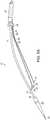
- Supporting wires 22, 23are fixed at one end and extend substantially parallel to a major axis of control lumen 12. Supporting wires 22, 23 are free at an end opposite to the fixed end. As shown in FIGS. 5A , 5B and 5C , supporting wires 22, 23 are fixed at proximal ends 24, 25 and are free at distal ends 26, 27. In an embodiment, distal ends 26, 27 of supporting wires 22, 23 are arcuate. Further, supporting wires 22, 23 include cantilever sections 28, 29 that are proximate (near) to proximal ends 24, 25. Typically, supporting wires 22,23 are formed of a suitable surgical-grade metal, such as stainless steel, or a super-elastic alloy, preferably a nitinol shape memory alloy.
- the length of supporting wires 22, 23typically is in a range of about 50 mm to about 75 mm or in a range of about 75 mm to about 100 mm, preferably about 75 mm.
- the wire diameter at the arcuate endis reduced to ensure that it is easy to straighten and remains very flexible and atraumatic. Supporting wires prevent retroflex during deployment of a stent graft, as depicted in FIG. 4 .
- Outer control tube 30, shown in FIGS. 5B and 5Cextends about control lumen 12 and is slideable along control lumen 12.
- suitable materials of control lumen 12include PEEK.
- outer control tube 30has an internal diameter in a range of between about 1.27mm (0.050 inches) and about 1.52mm (0.060 inches), preferably about 1.40mm (0.055 inches), and an outer diameter in a range of between about 1.78mm (0.070 inches) and about 1.91mm (0.075 inches), preferably about 1.80mm (0.071 inches), whereby the thickness of a wall of outer control tube 30, typically, has a range of between about 0.178mm (0.007 inches) and about 0.229mm (0.009 inches), preferably about 0.203mm (0.008 inches).
- Outer control tube 30includes proximal end 32 and distal end 34.
- Buttress 36is affixed to outer control tube 30, such as at proximal end 32 of outer control tube 30.
- Supporting wires 22are fixed at inferior side of buttress 36, thereby causing supporting wires 22 to be clustered.
- Buttress 36is formed of a suitable material, such as PEEK, and typically has an outer diameter in a range of between about 5.08mm (0.200 inches) and about 7.62mm (0.300 inches), such as about 5.08mm (0.200 inches), about 5.72mm (0.225 inches), about 6.35mm (0.250 inches), about 6.99mm (0.275 inches) and about 7.62mm (0.300 inches).
- Buttress 36can be sized to fit into the inner diameter of introducer sheath 92.
- at least one supporting wire 22, 23is fixed directly to control lumen 12, without fixing element 37, and fixing element 37 need not be present.
- Pusher support tube 38extends proximally from buttress 36.
- wires 22,23are fixed to control lumen 12 by fixing element 37 which is separated from buttress 36 and pusher support tube by a length of outer control tube 30.
- suitable materials of fixing element 37include PEEK.
- Fixing element 37can be an oblong shape to reduce profile on the opposite side of where the supporting wires are attached.
- Apex clasp 40shown in FIGS. 5B and 5C , is fixed to distal end 34 of outer control tube 30 and is slidable along control lumen 12 with movement of outer control tube 30.
- Apex clasp 40includes tines 42 that are in mating relation with receiving section 44 of the apex clasp 40.
- tines 42 of apex clasp 40are formed of a suitable material, such as stainless steel, while receiving section 44 is formed of a suitable material, such as PEEK or stainless steel.
- Tines 42are dimensional to receive at least one proximal apex of a clasping stent of a stent graft ( FIG.
- apex clasp 40is operable separately from outer control tube 30, whereby outer control tube 30 and supporting wires 22, 23 can be retracted independently of actuation of apex clasp 40, as also shown in FIG. 5C . Separate and independent actuation of apex clasp 40 can be obtained by attachment of apex clasp 40 to tube 43 that extends between outer control tube 30 and control lumen 12.
- apex clasp 40is attached to outer control tube 30, fixing element 37 is attached to outer control tube 30 and supporting wires 22, 23 are attached to fixing element 37, whereby apex clasp 40 and supporting wires 22, 23 are jointly retracted by actuation or movement of outer control tube 30.
- supporting wires 22, 23include bulbous tips 50, 51 at distal ends 26, 27, respectively, and stops 52, 53, respectively, having a diameter greater than that of supporting wires 22, 23, proximate to free and distal ends 26, 27 of supporting wires 22, 23.
- Stent graft 60shown in FIGS. 7A , 7B and 7J , extends about control lumen 12, supporting wires 22, 23 and outer control tube 30 of system 10.
- Inner sheath 80extends about stent graft 60, which, in turn, extends about pusher support tube 38 and is independent and moveable from pusher support tube 38.
- Sheath lumen 81typically is formed of PEBAX®, polyether block amine and can include a stainless steel braiding on the interior.
- Inner sheath 80extends about stent graft 60, thereby at least partially constraining stent graft 60 prior to deployment at a surgical site.
- Radiopaque marker 78is affixed to superior side of stent graft 60 at a distance in a range of about 40 mm and about 60 mm, such as about 40 mm, about 45 mm, about 50 mm, about 55 mm, about 60 mm distal, to proximal end 70 of stent graft 60.
- Radiopaque marker 88is fixed to inner sheath 80 by, for example, at least one stitch, and is longitudinally aligned with, but offset from radiopaque marker 78 of stent graft 60.
- Radiopaque marker 88can be asymmetric in shape, such as a D-shape, as shown in FIGS. 12B , 12C and 15C .
- stent graft 60includes graft 62 and at least one radiopaque marker 79.
- radiopaque marker 79is a dumb-bell or elongate shape.
- suitable materials of graft 62include PET.
- the PET of graft 62is woven.
- stent graft 60can be a bifurcated stent graft having two long legs, and a short and long leg, or two short legs, as shown in FIGS. 7G, 7H, 7I , respectively.
- Graft 62is supported by stents 64, which typically are formed of a suitable material, such as a shape memory metal or super elastic nickel titanium alloy, such as nitinol shape memory alloy. Typically, stents 64 are sewn to graft 62 to thereby support graft 62. Stents 64 can be located either within (inside) or outside of a lumen defined by graft 62. Crown stent 68 is inside the lumen of graft 62 and supports proximal end 70 of graft 62. Clasping stent 72, is distal to crown stent 68, relative to the patient. Stent grafts can further include at least one hook or barb, not shown.
- stents 64typically are formed of a suitable material, such as a shape memory metal or super elastic nickel titanium alloy, such as nitinol shape memory alloy.
- Stents 64can be located either within (inside) or outside of a lumen defined by graft 62.
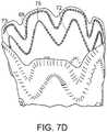
- clasping stent 72includes exposed proximal apices 73, 75, which are located within a lumen defined by graft 62. Proximal apices 73, 75, are dimensional for engagement with tines 42 of apex clasp 40, as shown in FIG. 7E .
- longitudinal support 74extends along a major axis of stent graft 60 and is affixed to an outside surface of stent graft 60. As shown in FIG.
- longitudinal support 74is on one side of a plane bisecting a major longitudinal axis of stent graft 60, that side being superior to any curve of control lumen 12 when stent graft 60 is secured by systems 10, 11, 13.
- exposed proximal apices 73, 75are on the side superior to a curve of control lumen 12 and are located proximal to a proximate end of longitudinal support 77.
- longitudinal support 74is substantially reverse-mirror symmetrical with respect to the major longitudinal axis of stent graft 60.
- a second side of stent graft 60 opposite to that which includes longitudinal support 74,is free of longitudinal support.
- Longitudinal support 74 at superior portion of stent graft 60can assist in preventing collapse of the superior portion consequent to compliance by stent graft 62 to curvature of an aorta at a surgical site at an aneurysm, where stent graft 60 is to be deployed.
- longitudinal support 74is curved.
- longitudinal support 74has centerline 77 that is parallel to the longitudinal axis of stent graft 60.
- Longitudinal support 74when curved, can be curved with respect to the centerline 77 in a manner that is about a mirror image of a portion of longitudinal support 74 on either side of a longitudinal plane of centerline 77, which is referred to herein as "reverse-mirror symmetrical.”
- stent graft 60can include longitudinal support 74 affixed, such as sewn, to the outside of graft 62, as shown in FIG. 7C .
- longitudinal support 74affixed, such as sewn, to the outside of graft 62, as shown in FIG. 7C .
- the longitudinal supportis not present on graft 62.
- stent graft 60includes at least one suture loop 76 on an inside surface of graft 62. Distal ends 26, 27 of supporting wires 22, 23 extend through suture loops 76, whereby supporting wires 22, 23 can be released from suture loops 76 by proximal retraction of supporting wires 22, 23 toward the surgeon. Referring back to FIG. 7E , exposed proximal apices 73, 75 are secured to systems 11, 13 by tines 42 of apex clasp 40.
- inner sheath 80is tapered between proximal end 82 and distal end 84, whereby the diameter of a lumen defined by inner sheath 80 is greater at distal end 84 than at proximal end 82. Further, inner sheath 80 is flared downwardly at inferior portion 83 of distal end 84. Further, the flared opening is asymmetric. Inferior portion 83 can be tapered distally as shown in FIG. 9A or straight relative to the most proximal end of inner sheath 80 as shown in FIG. 9B . As shown in FIG. 10 , triangular piece 85 of inner sheath 80 is attached at inferior portion 83 of distal end 84. In an alternative embodiment, shown in FIGS. 11A and 11B , inner sheath 80 defines a distal opening that is not flared or is not asymmetric. Inner sheath 80 includes major longitudinal axis 87.
- nose cone 18defines proximal cavity 86 at a proximal end 87 of nose cone 18.
- Distal end 84 of inner sheath 80can fit within proximal cavity 86, whereby retraction of inner sheath 80 from nose cone 18 releases distal end 84 of inner sheath 80 from proximal cavity 86.
- radiopaque marker 88is affixed to superior portion 90 of inner sheath 80.
- Inner sheath 80has inferior portion 91.
- Sufficient partial deployment of stent graft 60 to finalize positioning of proximal end 70 of stent graft 60 at a surgical sitewill be indicated by alignment and, preferably, superimposing of radiopaque markers 78 and 88, as shown in FIG. 12C .
- the inner sheath containing the stent graftis constrained prior to delivery by introducer sheath 92, shown in FIG. 13 .
- Nose cone 18when fully retracted, forms an interference fit with distal end 94 of introducer sheath 92, thereby sealing the stent graft and inner sheath within introducer sheath 92 for delivery to a patient and within the patient to the surgical site where the stent graft is to be deployed.
- Introducer sheath 92is, in turn, affixed to handle 96 of system 10, 11, 13, 100.
- a method of the inventionincludes advancing introducer sheath 92, while nose cone 18 is fully retracted, and in interfering relation with introducer sheath 92, endoluminally within an artery of a patient until nose cone 18 is proximate to a surgical site of a patient.
- Control lumen 12, outer control tube 30, pusher support tube 38, apex clasp 40, and sheath lumen 81are all independently moveable from handle 96 ( FIG. 13 ).
- the surgical sitecan be, for example, an aneurysm site 118 of, for example, an abdominal aorta, ascending aorta, a thoracic aorta or a descending aorta.
- advancement of system 10, 11, 13 through an artery of a patienttypically occurs by first introducing a guidewire through the aorta from a femoral artery of the patient (transfemoral access) to beyond the intended deployment site.
- Guidewire 20extends through control lumen 12 of system 10, 11, 13.
- System 10, 11, 13is then advanced along the guidewire until nose cone 18 and introducer sheath 92 are proximal, relative to the surgeon, of the surgical site, as shown in FIG. 14A .
- Nose cone 18, control lumen 12, pusher tube support 38, stent graft 60 and inner sheath 80are then all advanced beyond introducer sheath 92, until nose cone 18 and proximal end 70 of stent graft 60 are distal to the aneurysm, relative to the surgeon, as shown in FIG. 14B , at which point stent graft 60 and inner sheath 80 will no longer be constrained by introducer sheath 92.
- stent graft 60will be constrained within inner sheath 80, which has a larger internal diameter than that of introducer sheath 92 once inner sheath 80 and stent graft 60 have been advanced beyond introducer sheath 92.
- Inner sheath 80is then retracted relative to the remainder of system 10, 11, 13 as shown in FIG. 14C , wherein supporting wires 22, 23 (not shown) prevent rotation of inferior portion 5 of proximal end 4 of stent graft 60, also known as "retroflex.” Supporting wires 22, 23 are then withdrawn by the merger, along with activation of apex clasp 40, if present, to release stent graft 60.
- Inner sheath 80is then fully retracted to fully deploy stent graft 60, as shown in FIG. 14D .
- System 10, 11, 13is then withdrawn through deploying stent graft 60, as shown in FIG. 14E .
- the same general methodcan be employed to deploy similar stent grafts at surgical sites other than the thoracic aorta or aortic arch, including, for example, the descending aorta or ascending aorta; or bifurcated stent grafts at the abdominal aorta.
- inner sheath 80is then partially retracted relative to control lumen 12 and the pusher support tube to thereby expose proximal end 70 of stent graft 60.
- inner sheath 80is retracted by retraction of sheath lumen 60 until the radiopaque marker 78 on stent graft 60 shifts from a position of non-alignment with radiopaque marker 88, as shown in FIG. 15C , to a position of alignment with radiopaque marker 88, as shown in FIG. 15E , a detail of which is shown in FIG. 15B .
- supporting wires 22prevent rotation of an inferior portion 5 of proximal end 70 of stent graft 60 in a generally longitudinal direction parallel to that of a major axis of control lumen 12 at proximal end 70 by providing resistance to that rotation through longitudinal restraint imposed by supporting wires 22 on suture loops 76 of stent graft 60.
- the stent graft and the inner sheatheach include a radiopaque marker longitudinally aligned along a path of relative movement of the inner sheath and stent graft during deployment of the stent graft, and spaced apart from each other, whereby the partial retraction of the inner sheath will cause overlap of the radiopaque markers.
- the radiopaque markersare on superior portions of the inner sheath and the stent graft.
- the radiopaque marker in the inner sheathis asymmetric, such as is D-shaped, wherein a straight portion of the D-shaped marker is aligned with a major longitudinal axis of the inner sheath.
- the radiopaque marker of the stent graftis elongate and substantially aligned with the major longitudinal axis of the inner sheath.
- Stent graft 60can then be rotated about its major longitudinal axis or otherwise positioned by the surgeon by handle 96 ( FIG. 13 ). Once proximal end 70 is properly positioned by the surgeon, apex clasp 40, if present, can be remotely activated by the surgeon to release exposed proximal apices 66 within stent graft 60 ( FIG. 15D ). Control lumen 12, pusher support tube 38 and sheath lumen 81 can then be retracted, separately or jointly ( FIGS. 5A through 5E ). Retraction of pusher support tube 38 will withdraw supporting wires 22 from suture loops 76.
- system 11 or 13lack supporting wires 22, 23, and fixing element 37.
- a similar method described abovewould be employed to deploy stent graft 60, with the exception that supporting wires would not be present.
- At least one exposed proximal apex 73, 75 of clasping stent 72would be engaged with tines 42 of apex clasp.
- inner sheath 80includes triangle piece 85, shown in FIG. 10 .
- this embodimentwould be most suitable for implantation of stent graft 60 into a vessel, such as a blood vessel ( e.g., an artery) having an internal diameter of equal to or less than about 27 mm (e.g., about 20 mm, about 22 mm, about 24 mm, about 26 mm, and 27 mm).
- Stent graft 60 in this embodimenttypically would have an expanded external diameter in a range of between about 22 mm and about 30 mm (e.g., about 25 mm).
- inner sheath 80includes distal end 84 having a greater diameter than the remainder of inner sheath 80.
- Nose cone 18defines proximal cavity 86, as can be seen in FIG. 17 following advancement of nose cone 18, stent graft 60 and inner sheath 80 beyond introducer sheath 92, inner sheath 80 is retracted by retracting sheath lumen 81 sufficient to release distal end 84 of inner sheath 80 from proximal cavity 86 of nose cone 18, as shown in FIG. 18 .
- Proximal end 70 of stent graft 60thereby expands to a constrained diameter equal to that of the internal diameter of distal end 84 of inner sheath 80.
- radiopaque markers 78 and 88overlap upon release of proximal end 70 of stent graft 60 from proximal cavity 86 of nose cone 18.
- inner sheath 80includes second radiopaque marker 98, which overlaps radiopaque marker 78 of stent graft 60 upon release of proximal end 82 of inner sheath 80 from proximal cavity 86.
- radiopaque marker 98would be distal to radiopaque marker 88, and radiopaque markers 78 and 88 would overlap when sheath 80 is partially retracted from stent graft 60. The surgeon can then orient proximal end 70 of stent graft 60 prior to partial or complete deployment of stent graft 60, Where complete deployment follows, the presence of supporting wires 22 is optional.
- nose cone 18is retracted within stent graft 60 by retraction of control lumen, as shown in FIGS. 19A through 19D .
- the surgeoncan then further advance stent graft 60 and inner sheath, either without, or jointly with, nose cone 18, until proximal end 78 of stent graft 60 is properly positioned at the surgical site, such as by abutment or near abutment with an anatomical feature, such as a heart valve (e.g., aortic valve).
- a heart valvee.g., aortic valve
- sheath lumen 81 and inner sheath 80can be retracted, either with or without retraction of nose cone 18, to at least partially deploy stent graft 60.
- supporting wires 22restrain an inferior portion of proximal ends 70 from rotating back toward the remainder of stent graft 60 in a direction generally longitudinal to a major axis of stent graft 60.
- apices 66are released from tines 42 of apex clasp 40 by remote retraction of tines 42 at handle 96, and system 11, 13 is retracted to fully deploy stent graft 60 at the surgical site.
- system 11, 13is retracted to fully deploy stent graft 60 without use of supporting wires 22 or apex clasp 40.
- system 100includes control lumen 102 to which is affixed nose cone 104.
- Outer control tube 106extends about control lumen 102 but is not connected to nose cone 104.
- At least one supporting wire 108is fixed to outer control tube 106.
- Supporting wire 108extend substantially parallel to a major axis of control lumen 102 and are free at an end opposite to where it is fixed to outer control tube 106.
- free end 110 of supporting wire 108is arcuate.
- Stent graft 60is disposed about outer control tube 106 and about supporting wires 108.
- Inner sheath 112is fixed to nose cone 104 and extends about stent graft 60.
- stent graft 60can be secured by an apex clasp (not shown), as discussed above, at proximal end 70 of stent graft 60.
- Control lumen 102, outer control tube 106 and an apex clasp, if present,can be controlled at handle 96 to which they are all connected.
- An introducer sheathextends about inner sheath 112, stent graft 60, outer control tube 106 and control lumen 102, and is in interfering relation with nose cone 104 prior to deployment of inner sheath 112 and stent graft 60.
- System 100is particularly suitable for use where an endoluminal prosthesis is not implanted by directing the prosthesis through an femoral artery of a patient (transfemoral access), but alternatively introduced through the left ventricle of a patient's heart (transapical access).
- introducer sheath 92containing stent graft 60, is directed through the left ventricle of a patient's heart until stent graft 60 spans the diseased portion of an artery, such as an aneurysm at the ascending aorta.
- Control lumen 102is then further advanced, thereby causing nose cone 104 to further advance and pull inner sheath 112 with it, thereby exposing and deploying stent graft 60.
- Supporting wiresprovide longitudinal resistance to prevent movement of stent graft 60 during deployment. Once stent graft 60 is fully exposed, or deployed, outer control tube 106 is advanced to release supporting wires from loops within stent graft 60, as described above. System 100 can then be retracted through stent graft 60 and removed from the patient.
- system 120includes control lumen 122 having distal end 124 and nose cone 126 fixed at distal end 124.
- Stent graft 128extends about control lumen 122.
- At least one suture 130extends from nose cone 126 to proximal end 132 of stent graft 128, and from stent graft 128 to a fixed location 134 on control lumen 122.
- Suture 130is releaseable from stent graft 128 by remote activation, whereby suture 130 separates from nose cone 126 to thereby deploy stent graft 128.
- nose cone 126includes longitudinal slot 133 at a distal end of suture 130 in interfering relation with slot 133, whereby increased tension in suture 130 causes suture 130 to come free of longitudinal slot 133 and, therefore, from nose cone 126.
- suture 130includes an expanded portion 131, such as knot, in interfering relation with the loop or the hole, not shown, whereby longitudinal movement of portion 130 of distal end 132 of stent graft 128 back toward the surgeon is prevented while distal end of suture 130 is in interfering relation with nose cone 126.
- suture 130When suture 130 is withdrawn from the longitudinal slot, suture can be withdrawn through the loop or the hole to thereby release proximal end 132 of stent graft 128.
- Apex clasp 136is controlled by outer control tube 138.
- system 120locks apex clasp 136 and outer control tube 138.
- the suture employed in the systems of FIGS. 21A and 21Bcan be a thread that includes a biocompatible material, such as a suture gut, or a metal (e.g., wire) that includes stainless steel or a shape memory alloy.
- inner sheath 210 about stent graft 60 and extending from inner sheath liner 212includes proximal perforated portion 214 that defines through-holes.
- the through-holescan be defined by a mesh or fabric of perforation portion 214 as shown in FIG. 22A or as distinct openings, such as longitudinal through-hole opening 216 shown in FIG. 22B , that extend substantially parallel to a major axis of inner sheath 210.
- the through-holeshave a diameter equal to or greater than about 25 mm.
- the through-holespermit relatively continuous blood flow through stent graft 60 from aortic valve 218 through aortic arch 220 in the direction shown by arrows 222 during implantation of stent graft 60.
- Inner sheath of the invention defining through-holescan also be employed at other intended surgical sites, such as the mesenteric artery or the celiac artery.
Landscapes
- Health & Medical Sciences (AREA)
- Engineering & Computer Science (AREA)
- Biomedical Technology (AREA)
- General Health & Medical Sciences (AREA)
- Veterinary Medicine (AREA)
- Transplantation (AREA)
- Oral & Maxillofacial Surgery (AREA)
- Public Health (AREA)
- Life Sciences & Earth Sciences (AREA)
- Animal Behavior & Ethology (AREA)
- Cardiology (AREA)
- Vascular Medicine (AREA)
- Heart & Thoracic Surgery (AREA)
- Gastroenterology & Hepatology (AREA)
- Pulmonology (AREA)
- Chemical & Material Sciences (AREA)
- Inorganic Chemistry (AREA)
- Dermatology (AREA)
- Medicinal Chemistry (AREA)
- Epidemiology (AREA)
- Prostheses (AREA)
- Media Introduction/Drainage Providing Device (AREA)
Description
- Endoluminal prostheses for treatment of arterial disease have come into wide use over the past several years. Typically, such prosthesis include a luminal graft material of woven polyethylene terephthalate (PET) supported by self-expanding stents, which are often formed of a shape memory alloy.
- Endoluminal stent grafts, so called because they are deployed within a lumen of a blood vessel, are employed to support diseased arterial tissue, such as arterial tissue that has been weakened to thereby form aneurysms, psuedoaneurysms, dissections, penetrating ulcers, and intramural hematomas. Arteries that are most susceptible to these type of disease states, and which would be treatable by implantation of endoluminal stent grafts include, for example, the abdominal aorta, the thoracoabdominal aorta, the descending thoracic aorta, the aortic arch, and the ascending aorta.
- Generally, endoluminal prostheses are implanted by femoral access through the femoral artery of a patient. Alternatively, endoluminal devices can be implanted by transapical access through the apex of the heart and the left ventricle to, for example, the ascending aorta and may, when deployed, essentially abut the aortic valve at the sinotubular junction, the region of the ascending aorta between the aortic sinuses (of Valsalva) and where the normal configuration of the aorta is attained.
- Implantation of a self-expanding stent graft prosthesis generally requires that it be constrained within a narrow diameter during delivery to the deployment site within the patient. Often, the diameter is constrained by containing the prosthesis within at least one sheath that is capped at a distal end, respective to the surgeon, with a pliable nose cone. The sheath and nose cone are guided through the lumen of the artery by a guidewire that extends axially through and extends from the nose cone of the delivery device within which the prosthesis is contained. Once the nose cone and sheath have been advanced to the surgical site where the prosthesis is to be deployed, the sheath containing the prosthesis can be rotated, if necessary, to properly orient the prosthesis, and then one or more sheaths are retracted to allow the prosthesis to expand, thereby deploying the prosthesis at the intended treatment site.
EP 1 982 677 provides an example of a delivery system for a stent graft.- Several problems can occur by remote deployment of endoluminal prosthesis from a constraining sheath. For example, if the portion of the aorta where the prosthesis is to be deployed has an extreme tortuosity or tight radius of curvature, such as the arch of the aorta, which is arcuate, or because the disease state of the aorta has caused the aorta to have an irregular shape, simple retraction of the sheath, or sheaths, from the prosthesis can cause the proximal end (cranially, with respect to the patient) of the stent graft to fail to properly align with the arterial wall. For example, a portion of the proximal end of the stent graft can rotate backwards, toward the surgeon, adjacent to the curve in the vessel thereby causing a failure of the proximal end of the stent graft to form a seal with the artery, This phenomenon is commonly referred to as a "retroflex." Mostly commonly, rotation of a portion of the proximal end of the stent graft during deployment occurs at an inferior side of a stent graft being deployed within the aortic arch, which has a relatively large diameter. Another problem includes the formation of a "bird's beak," also referred to as a "gap," caused by the stent graft failing to properly conform to an inferior portion curve of the aorta, which most commonly occurs as a result of a deployment sequence that forces the most proximal covered stent of the prosthesis to be deployed last.
- Another problem occurs when the stent graft must be deployed close to the junction between the ascending aorta and the aortic valve. Specifically, the nose cone employed to assist guidance of the endoluminal prosthesis to the surgical site restricts the ability of the surgeon to deploy the prosthesis contained in the sheath as close to the ascending aorta at its point of origin.
- Therefore, a need exists for a delivery system for implanting a prosthesis and methods of implanting a prosthesis that minimizes or overcomes the above-referenced problems.
- The invention generally is directed to a system for implanting a prosthesis and, specifically, for implanting an endoluminal prosthesis at a diseased site of an aorta. The invention provides a system for implanting a stent graft according to claim 1.
- In one embodiment of the invention, the system includes a control lumen, a nose cone fixed at a distal end of the control lumen, and at least one supporting wire fixed at one end, substantially parallel to a major axis of the control lumen and free at an opposite end. The free end of at least one of the supporting wires is arcuate.
- In another embodiment, the system of the invention includes a control lumen, a nose cone fixed at a distal end of the control lumen, a stent graft extending about the control lumen, and at least one suture extending from the nose cone to a proximal end of the stent graft and from the stent graft to a fixed location on the control lumen. The suture is releasable from the stent graft by remote activation, whereby retraction of the control lumen releases the suture from the nose cone to thereby deploy the stent graft.
- In still another embodiment of the invention, the system includes a control lumen, a nose cone fixed at a distal end of the control lumen, and an inner sheath extending above the control lumen that defines a distal opening at a distal end of the inner sheath. The nose cone is retractable within the inner sheath.
- The specification describes a method for implanting a prosthesis that includes delivering a stent graft through an artery to an aneurysm site of a patient, the stent graft being radially constrained by an inner sheath and supported at least in part by a control lumen. The stent graft is also longitudinally constrained by at least one supporting wire extending from a nose cone, from the control lumen or from an outer control tube extending about and slideable along the control lumen, wherein the free end of at least one of the supporting wires is arcuate and extends through a loop hole within a proximal end of the stent graft. The inner sheath is partially retracted from the stent graft, whereby the supporting wire at least partially restricts longitudinal movement of the proximal end of the stent graft until the proximal end of the stent graft is secure within the artery, to thereby prevent rotation of a portion of the proximal end of the stent graft at an inferior portion of the artery. The inner sheath and supporting wire are then retracted, thereby removing the supporting wire from the loop and deploying the stent graft within the artery at the aneurysm site of the patient. The inner sheath and supporting wire can be jointly retracted, thereby removing the supporting wire from the loop and deploying the stent graft within the artery at the aneurysm site of the patient.
- The disclosed method further includes the steps of retracting the nose cone within the stent graft after partially retracting the inner sheath. The stent graft is then advanced to a final position within the artery. Thereafter, the inner sheath, nose cone and supporting wires are retracted to fully deploy the stent graft within the artery at the aneurysm site of the patient.
- The disclosed method includes delivering a stent graft through an artery to an aneurysm site of the patient. The stent graft is radially constrained by an inner sheath and supported at least in part by a control lumen, and is further constrained by at least one suture extending from a nose cone at a distal end of the control lumen to a proximal end of the stent graft and extending from the proximal end of the stent graft to a fixed location on the control lumen. This suture is releasable from the nose cone and the stent graft by remote activation. The inner sheath is retracted from the stent graft, whereby the suture at least partially restricts longitudinal movement of the proximal end of the stent graft until the proximal end of the stent graft is secure within an artery, thereby preventing rotation of a portion of the proximal end of the stent graft at an inferior portion of the artery. This suture is then remotely activated, whereby the suture is released from the nose cone and releases the stent graft. The inner sheath is then retracted to thereby deploy the stent graft within the artery at the aneurysm site of the patient.
- The specification discloses a method for implanting a prosthesis comprising a control lumen, a nose cone fixed at a distal end of the control lumen, a sheath lumen extending about the control lumen and slideable along the control lumen and an inner sheath extending distally from the sheath lumen and about the control lumen between the nose cone and the sheath lumen, the inner sheath defining at least one through-hole at a proximal end of the inner sheath proximate to the sheath lumen.
- In yet another embodiment, the invention is a system for implanting a prosthesis comprising a control lumen, a nose cone fixed at a distal end of the control lumen, an outer control tube extending about the control lumen, an apex clasp at a distal end of the outer control lumen and slideable along the control lumen, a sheath lumen extending about the control lumen, an inner sheath extending distally from the sheath lumen about the outer control tube, the inner sheath including a triangular piece at a distal end of the inner sheath; and a stent graft between the outer control tube and the inner sheath, the stent graft including a proximal end proximate to the nose cone having a clasping stent at the proximal end, wherein the clasping stent has at least one exposed proximal apex releasably held by the apex clasp.
- The specification discloses a method for implanting a prosthesis, comprising the steps of delivering a stent graft through an artery to a point distal, relative to the patient, of an aneurysm site of a patient, the stent graft being radially constrained by an inner sheath, and affixed to an outer control tube, and wherein the inner sheath is constrained by an introducer sheath, the stent graft and the inner sheath each including at least one radiopaque marker on superior portions of the stent graft and the inner sheath, the radiopaque markers being separated along a major longitudinal axis of the inner sheath; advancing the inner sheath, the stent graft and the outer control lumen beyond the introducer sheath until the stent graft spans the aneurysm site of the patient; partially retracting the inner sheath from the stent graft, whereby the radiopaque marker of the stent graft overlaps to the radiopaque marker of the inner sheath; positioning a proximal end of the stent graft within the artery; and fully retracting the inner sheath to thereby fully deploy the stent graft within the artery.
- This invention has many advantages. For example, the supporting wire of the system for implanting a prosthesis provides longitudinal support for at least a portion of the proximal end of a stent graft, such as a portion of the proximal end of the stent graft that is located an inferior, or inner, portion of a curve, of the aortic arch. This longitudinal restraint limits rotation of a portion of a proximal end of an endoluminal stent at an inferior portion of the aortic arch lumen, thereby causing the proximal end of the stent graft to be properly seated in a plane that is essentially transverse to a major longitudinal axis extending through the aortic lumen at the proximal end of the stent graft. Proper seating of the proximal end of the stent graft prevents seepage of blood beyond and under the prosthesis, thereby increasing the likelihood of successful implant and prolonging useful life of the prosthetic implant. Further, retraction of a nose cone within the stent graft prior to its deployment enables the prosthesis to be deployed within an ascending aorta of a patient essentially within abutting relation with a valve of the heart, thereby providing greater flexibility to the surgeon when placing the stent graft within a patient. In addition, retraction of the nose cone within the stent graft prior to deployment within an abdominal aorta of a patient permits refinements in the placement of the stent graft relative to the aneurysm site in the abdominal aorta, thereby providing greater flexibility to the surgeon when placing the stent graft within the patient. Another advantage of the invention is an inner sheath defining at least one through-hole that permits perfusion or continued flow of blood during deployment of a stent graft.
- The foregoing will be apparent from the following more particular description of example embodiments of the invention, as illustrated in the accompanying drawings in which like reference characters refer to the same parts throughout the different views. The drawings are not necessarily to scale, emphasis instead being placed upon illustrating embodiments of the present invention.
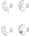
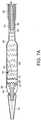
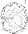
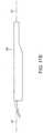
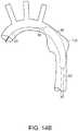
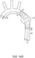
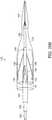
FIG. 1 depicts a prior art system for implanting a stent graft in a lumen of an aorta.FIG. 2 depicts prior art deployment of a stent graft in a lumen of a curved portion of an aorta from a sheath that permits a proximal end of the stent graft to rotate backward at an inferior portion.FIG. 3 depicts prior art full deployment of a stent graft with a kink caused by retroflex rotation of the proximal end of the stent graft.FIG. 4 depicts prior art deployment of a stent graft with a "bird's beak" caused by a sequence of deployment that frees the first proximal covered stent last.FIG. 5A depicts an embodiment of a system of the invention for implanting a prosthesis.FIGS. 5B and5C depict embodiments of systems of the invention that include an apex clasp for implanting a prosthesis.FIG. 6 depicts another embodiment of a system of the invention for implanting a prosthesis.FIGS. 7A ,7B and7J depict side and longitudinal cross-section views of a portion of embodiments of a system of the invention for implanting a prosthesis.FIGS. 7C and7K depict embodiments of a stent graft for use in a system of the invention for implanting a prosthesis.FIG. 7D depicts a crown stent and a clasping stent, with exposed proximal apices, located on the inside of a lumen defined by the graft suitable for use by the invention.FIG. 7E depicts engagement of the exposed proximal apices of the clasping stent with the tines of an apex clasp of the invention.FIG. 7F depicts an embodiment of the stent graft in an arch configuration, as it would be at a surgical site.FIGS. 7G, 7H and 7I depict various embodiments of the bifurcated stent grafts suitable for use with the system of the invention for implanting a prostheses.FIG. 8 depicts suture loops on an inside surface of the stent graft.FIGS. 9A and9B depict embodiments of an inner sheath in a system of the invention for implanting a prosthesis.FIG. 10 depicts an alternative embodiment of a distal end of an inner sheath in a system of the invention for implanting a prosthesis.FIGS. 11A and11B depict other alternative embodiments of an inner sheath in a system of the invention for implanting a prosthesis.FIG. 12A depicts an embodiment of the invention wherein a nose cone defines a proximal cavity at the proximal end of the nose cone.FIG. 12B depicts an embodiment of the invention wherein an inner sheath includes at least one radiopaque marker affixed to a superior portion of the inner sheath.FIG. 12C depicts a fluoroscopic rendering of an embodiment of the methods of the invention whereby partial deployment of a stent graft at a surgical site is indicated by alignment of at least one radiopaque marker of the stent graft and at least one radiopaque marker of an inner sheath.FIG. 13 depicts an embodiment of a system of the invention for implanting a prosthesis where an inner sheath containing a stent graft is constrained prior to delivery by a introducer sheath.FIGS. 14A-14E depict an embodiment of the invention during implantation of a prosthesis at an aneurysm site.FIGS. 15A-15E depict different views of an embodiment of the invention during deployment of a prosthesis.FIGS. 15B, 15C and15E depict fluoroscopic renderings of embodiments of the invention.FIG. 16 depicts an embodiment of the inner sheath in the system of the invention.FIGS. 17 and 18 depict yet another embodiment of the invention for implanting a prosthesis.FIGS. 19A-19D depict still another embodiment of the invention for implanting a prosthesis.FIGS. 20A and20B depict embodiments of the invention, for implanting a prosthesis by entry through the left ventricle of a patient's heart.FIG. 21A depicts an alternative embodiment of the invention, that includes at least one suture and an apex clasp.FIG. 21B depicts another alternative embodiment of the invention, that includes at least one suture.FIGS. 22A and 22B depict an embodiment of the invention that includes an inner sheath having at least one through-hole.- The features and other details of the invention, either as steps of the invention or as combinations of parts of the invention, will now be more particularly described and pointed out in the claims. It will be understood that the particular embodiments of the invention are shown by way of illustration and not as limitations of the invention. The principal features of this invention can be employed in various embodiments without departing from the scope of the invention.
- The present invention generally is directed to a system for implanting a stent graft within a vessel (e.g., artery) of a patient. The system employs at least one supporting wire to provide longitudinal support to prevent rotation toward the surgeon of a portion of a proximal end of an endoluminal stent graft during deployment of the stent graft. The proximal end of the stent graft is thereby properly seated at the surgical site proximate to an aneurysm or other diseased portion of an aorta, before complete deployment of the stent graft.
- The invention also includes a system that provides for retraction of a nose cone of a delivery system within an endoluminal stent graft prior to complete deployment of the stent graft, thereby permitting abutment of the stent graft to another anatomical feature, such as a heart or arterial valve, during deployment. In still another embodiment, an endoluminal graft delivery system includes a sheath at one end of the endoluminal graft, the graft being releasable from the endoluminal graft and permitting perfusion distal to the graft.
- As represented in
FIGS. 1-4 , deployment of stent graft 1, also referred to herein as an "endoluminal prosthesis" or "prothesis," within the lumen of anaorta 2, particularly a portion of an aorta that exhibits a curvature, such as the arch of the aorta, from the end of asheath 3, can cause at aproximal end 4 of the prosthesis to rotate backward at aninferior portion 5 of, in a generally longitudinal direction, toward the surgeon, as shown inFIG. 2 , thereby causing the fully deployed prosthesis to be folded at the proximal end and creating akink 6 within the prosthesis, as shown inFIG. 4 or distal buckling of the entire proximal end of the stent graft.FIG. 4 depicts the formation of "bird's beak" 7. The formation of a "bird's beak" can occur with a prosthesis having a bare stent or stent covered with graft material at the proximal end of the prosthesis. - In an embodiment, the invention employs at least one supporting wire as a component of a system for delivering a prosthesis to provide longitudinal support, whereby rotation of the
proximal end 4 of the prosthesis during retraction of a constraining sheath is prevented, thereby resulting in deployment of the prosthesis in a fully extended manner, whereby folding back of an inferior portion of a proximal end of the prosthesis and consequent buckling, or crimping, of the prosthesis, as shown inFIGS. 3 and 4 , is essentially prevented. Retroflex or such rotation and consequent buckling of the prosthesis can occur in grafts with or without bare stents. A "bird's beak" is particularly prevalent in prostheses that do not have bare stents extending from the proximal (cranial) end of the graft portion of a stent graft. Such stent graft, also known as "non-bare stent grafts," can be employed as prostheses that, when deployed, abut other anatomical structures, such as heart valves. Lack of bare stents at the proximal end of an endoluminal stent graft can make deployment of the stent graft more difficult by providing limited opportunities to control expansion of self-expanding stents of the stent graft as a constraining sheath is retracted during deployment. As a consequence, the inferior portion or the entire portion of a proximal end of an endoluminal stent graft, has a tendency, as described above, to rotate back in a generally longitudinal direction to thereby cause an imperfect seal, possible retroflex or formation of a "bird's beak," as discussed above with respect toFIGS. 3 and 4 . The systems and methods of the invention prevent retroflex and the formation of a "bird's beak." - In embodiments of the invention, represented in
FIGS. 5A ,5B ,5C ,systems control lumen 12.Control lumen 12 typically is formed of a suitable metal, such as stainless steel, a shape memory metal or a super elastic nickel-titanium alloy, such as a nitinol shape memory alloy; a polymer, such as polyether ether ketone (PEEK); or any combination of a metal, alloy or polymer, in particular, a combination of a metal and an alloy.Control lumen 12 typically is arcuate and defines a lumen extending therethrough having a diameter in a range of between, for example, in a range of about 1.02mm (0.0040 inches) (about 0.76mm (0.0030 inches) to about 1.27mm (0.0050 inches)) ID (inner diameter) and about 1.27mm (0.050 inches) (about 1.02mm (0.040 inches) to about 1.52mm (0.060 inches)) OD (outer diameter).Control lumen 12 includesproximal end 14 anddistal end 16. Nose cone 18 is fixed atdistal end 16 ofcontrol lumen 12.Nose cone 18 is formed of a suitable material, such as TECOTHANE®, thermoplastic polyurethane elastomer polyether.Control lumen 12 extends throughnose cone 18, thereby permittingguidewire 20 to extend throughcontrol lumen 12 and fromnose cone 18, wherebysystems guidewire 20 endoluminally and through an artery (e.g., aorta) of a patient to a surgical site (e.g., ascending aorta, thoracic aorta, descending aorta, abdominal aorta).- Supporting
wires control lumen 12. Supportingwires FIGS. 5A ,5B and5C , supportingwires wires wires cantilever sections wires wires FIG. 4 . Outer control tube 30, shown inFIGS. 5B and5C , extends aboutcontrol lumen 12 and is slideable alongcontrol lumen 12. Examples of suitable materials ofcontrol lumen 12 include PEEK. Typically,outer control tube 30 has an internal diameter in a range of between about 1.27mm (0.050 inches) and about 1.52mm (0.060 inches), preferably about 1.40mm (0.055 inches), and an outer diameter in a range of between about 1.78mm (0.070 inches) and about 1.91mm (0.075 inches), preferably about 1.80mm (0.071 inches), whereby the thickness of a wall ofouter control tube 30, typically, has a range of between about 0.178mm (0.007 inches) and about 0.229mm (0.009 inches), preferably about 0.203mm (0.008 inches).Outer control tube 30 includesproximal end 32 anddistal end 34.Buttress 36 is affixed toouter control tube 30, such as atproximal end 32 ofouter control tube 30. Supportingwires 22 are fixed at inferior side ofbuttress 36, thereby causing supportingwires 22 to be clustered.Buttress 36 is formed of a suitable material, such as PEEK, and typically has an outer diameter in a range of between about 5.08mm (0.200 inches) and about 7.62mm (0.300 inches), such as about 5.08mm (0.200 inches), about 5.72mm (0.225 inches), about 6.35mm (0.250 inches), about 6.99mm (0.275 inches) and about 7.62mm (0.300 inches). Buttress 36 can be sized to fit into the inner diameter ofintroducer sheath 92. In another embodiment, not shown, at least one supportingwire lumen 12, without fixingelement 37, and fixingelement 37 need not be present.Pusher support tube 38 extends proximally from buttress 36. In another embodiment, shown inFIG. 5C ,wires lumen 12 by fixingelement 37 which is separated from buttress 36 and pusher support tube by a length ofouter control tube 30. Examples of suitable materials of fixingelement 37 include PEEK. Fixingelement 37 can be an oblong shape to reduce profile on the opposite side of where the supporting wires are attached.Apex clasp 40, shown inFIGS. 5B and5C , is fixed todistal end 34 ofouter control tube 30 and is slidable alongcontrol lumen 12 with movement ofouter control tube 30.Apex clasp 40 includestines 42 that are in mating relation with receivingsection 44 of theapex clasp 40. Typically, tines 42 ofapex clasp 40 are formed of a suitable material, such as stainless steel, while receivingsection 44 is formed of a suitable material, such as PEEK or stainless steel.Tines 42 are dimensional to receive at least one proximal apex of a clasping stent of a stent graft (FIG. 7E ), whereby actuation ofapex clasp 40, by retraction oftines 42 from receivingsection 44 ornose cone 18 will release the exposed proximal apex of at least one clasping stent during deployment of the stent graft at a surgical site.- Optionally,
apex clasp 40 is operable separately fromouter control tube 30, wherebyouter control tube 30 and supportingwires apex clasp 40, as also shown inFIG. 5C . Separate and independent actuation ofapex clasp 40 can be obtained by attachment ofapex clasp 40 totube 43 that extends betweenouter control tube 30 andcontrol lumen 12. - In an alternative embodiment, represented in
FIG. 6 ,apex clasp 40 is attached toouter control tube 30, fixingelement 37 is attached toouter control tube 30 and supportingwires element 37, wherebyapex clasp 40 and supportingwires outer control tube 30. Further, in an alternative embodiment, supportingwires bulbous tips wires wires Stent graft 60, shown inFIGS. 7A ,7B and7J , extends aboutcontrol lumen 12, supportingwires outer control tube 30 ofsystem 10.Inner sheath 80 extends aboutstent graft 60, which, in turn, extends aboutpusher support tube 38 and is independent and moveable frompusher support tube 38.Sheath lumen 81 typically is formed of PEBAX®, polyether block amine and can include a stainless steel braiding on the interior.Inner sheath 80 extends aboutstent graft 60, thereby at least partially constrainingstent graft 60 prior to deployment at a surgical site.Radiopaque marker 78 is affixed to superior side ofstent graft 60 at a distance in a range of about 40 mm and about 60 mm, such as about 40 mm, about 45 mm, about 50 mm, about 55 mm, about 60 mm distal, toproximal end 70 ofstent graft 60.Radiopaque marker 88 is fixed toinner sheath 80 by, for example, at least one stitch, and is longitudinally aligned with, but offset fromradiopaque marker 78 ofstent graft 60.Radiopaque marker 88 can be asymmetric in shape, such as a D-shape, as shown inFIGS. 12B ,12C and15C . - As shown in
FIGS. 7C and7K stent graft 60 includesgraft 62 and at least oneradiopaque marker 79. In an embodiment,radiopaque marker 79 is a dumb-bell or elongate shape. Examples of suitable materials ofgraft 62 include PET. Typically, the PET ofgraft 62 is woven. Alternatively,stent graft 60 can be a bifurcated stent graft having two long legs, and a short and long leg, or two short legs, as shown inFIGS. 7G, 7H, 7I , respectively.Graft 62 is supported bystents 64, which typically are formed of a suitable material, such as a shape memory metal or super elastic nickel titanium alloy, such as nitinol shape memory alloy. Typically,stents 64 are sewn to graft 62 to thereby supportgraft 62.Stents 64 can be located either within (inside) or outside of a lumen defined bygraft 62.Crown stent 68 is inside the lumen ofgraft 62 and supportsproximal end 70 ofgraft 62. Claspingstent 72, is distal to crownstent 68, relative to the patient. Stent grafts can further include at least one hook or barb, not shown. - As shown in
FIG. 7D , claspingstent 72 includes exposedproximal apices graft 62.Proximal apices tines 42 ofapex clasp 40, as shown inFIG. 7E . Referring toFIG. 7C ,longitudinal support 74 extends along a major axis ofstent graft 60 and is affixed to an outside surface ofstent graft 60. As shown inFIG. 7F ,longitudinal support 74 is on one side of a plane bisecting a major longitudinal axis ofstent graft 60, that side being superior to any curve ofcontrol lumen 12 whenstent graft 60 is secured bysystems proximal apices control lumen 12 and are located proximal to a proximate end oflongitudinal support 77. Further,longitudinal support 74 is substantially reverse-mirror symmetrical with respect to the major longitudinal axis ofstent graft 60. A second side ofstent graft 60 opposite to that which includeslongitudinal support 74, is free of longitudinal support.Longitudinal support 74 at superior portion ofstent graft 60 can assist in preventing collapse of the superior portion consequent to compliance bystent graft 62 to curvature of an aorta at a surgical site at an aneurysm, wherestent graft 60 is to be deployed. - Typically,
longitudinal support 74 is curved. Referring back toFIG. 7C ,longitudinal support 74 hascenterline 77 that is parallel to the longitudinal axis ofstent graft 60.Longitudinal support 74, when curved, can be curved with respect to thecenterline 77 in a manner that is about a mirror image of a portion oflongitudinal support 74 on either side of a longitudinal plane ofcenterline 77, which is referred to herein as "reverse-mirror symmetrical." - In an embodiment,
stent graft 60 can includelongitudinal support 74 affixed, such as sewn, to the outside ofgraft 62, as shown inFIG. 7C . In another embodiment shown inFIG. 7K the longitudinal support is not present ongraft 62. - As shown in
FIG. 8 ,stent graft 60 includes at least onesuture loop 76 on an inside surface ofgraft 62. Distal ends 26, 27 of supportingwires suture loops 76, whereby supportingwires suture loops 76 by proximal retraction of supportingwires FIG. 7E , exposedproximal apices systems 11, 13 bytines 42 ofapex clasp 40. - As can be seen in
FIGS. 9A and9B ,inner sheath 80 is tapered betweenproximal end 82 anddistal end 84, whereby the diameter of a lumen defined byinner sheath 80 is greater atdistal end 84 than atproximal end 82. Further,inner sheath 80 is flared downwardly atinferior portion 83 ofdistal end 84. Further, the flared opening is asymmetric.Inferior portion 83 can be tapered distally as shown inFIG. 9A or straight relative to the most proximal end ofinner sheath 80 as shown inFIG. 9B . As shown inFIG. 10 ,triangular piece 85 ofinner sheath 80 is attached atinferior portion 83 ofdistal end 84. In an alternative embodiment, shown inFIGS. 11A and11B ,inner sheath 80 defines a distal opening that is not flared or is not asymmetric.Inner sheath 80 includes majorlongitudinal axis 87. - In another embodiment of the invention, shown in
FIG. 12A ,nose cone 18 definesproximal cavity 86 at aproximal end 87 ofnose cone 18.Distal end 84 ofinner sheath 80 can fit withinproximal cavity 86, whereby retraction ofinner sheath 80 fromnose cone 18 releasesdistal end 84 ofinner sheath 80 fromproximal cavity 86. - Referring to
FIG. 12B ,radiopaque marker 88 is affixed tosuperior portion 90 ofinner sheath 80.Inner sheath 80 hasinferior portion 91. Sufficient partial deployment ofstent graft 60 to finalize positioning ofproximal end 70 ofstent graft 60 at a surgical site will be indicated by alignment and, preferably, superimposing ofradiopaque markers FIG. 12C . - The inner sheath containing the stent graft, is constrained prior to delivery by
introducer sheath 92, shown inFIG. 13 .Nose cone 18 when fully retracted, forms an interference fit withdistal end 94 ofintroducer sheath 92, thereby sealing the stent graft and inner sheath withinintroducer sheath 92 for delivery to a patient and within the patient to the surgical site where the stent graft is to be deployed.Introducer sheath 92 is, in turn, affixed to handle 96 ofsystem - A method of the invention includes advancing
introducer sheath 92, whilenose cone 18 is fully retracted, and in interfering relation withintroducer sheath 92, endoluminally within an artery of a patient untilnose cone 18 is proximate to a surgical site of a patient.Control lumen 12,outer control tube 30,pusher support tube 38,apex clasp 40, and sheath lumen 81 (FIGS. 5 ,et seq.), are all independently moveable from handle 96 (FIG. 13 ). The surgical site can be, for example, ananeurysm site 118 of, for example, an abdominal aorta, ascending aorta, a thoracic aorta or a descending aorta. As shown inFIGS. 14A-14E advancement ofsystem Guidewire 20 extends throughcontrol lumen 12 ofsystem System nose cone 18 andintroducer sheath 92 are proximal, relative to the surgeon, of the surgical site, as shown inFIG. 14A .Nose cone 18,control lumen 12,pusher tube support 38,stent graft 60 and inner sheath 80 (FIG. 5 ,et seq.) are then all advanced beyondintroducer sheath 92, untilnose cone 18 andproximal end 70 ofstent graft 60 are distal to the aneurysm, relative to the surgeon, as shown inFIG. 14B , at whichpoint stent graft 60 andinner sheath 80 will no longer be constrained byintroducer sheath 92. Instead,stent graft 60 will be constrained withininner sheath 80, which has a larger internal diameter than that ofintroducer sheath 92 onceinner sheath 80 andstent graft 60 have been advanced beyondintroducer sheath 92.Inner sheath 80 is then retracted relative to the remainder ofsystem FIG. 14C , wherein supportingwires 22, 23 (not shown) prevent rotation ofinferior portion 5 ofproximal end 4 ofstent graft 60, also known as "retroflex." Supportingwires apex clasp 40, if present, to releasestent graft 60.Inner sheath 80 is then fully retracted to fully deploystent graft 60, as shown inFIG. 14D .System stent graft 60, as shown inFIG. 14E . The same general method can be employed to deploy similar stent grafts at surgical sites other than the thoracic aorta or aortic arch, including, for example, the descending aorta or ascending aorta; or bifurcated stent grafts at the abdominal aorta. - More specifically, as can be seen in
FIG. 15A ,inner sheath 80 is then partially retracted relative to controllumen 12 and the pusher support tube to thereby exposeproximal end 70 ofstent graft 60. Preferably,inner sheath 80 is retracted by retraction ofsheath lumen 60 until theradiopaque marker 78 onstent graft 60 shifts from a position of non-alignment withradiopaque marker 88, as shown inFIG. 15C , to a position of alignment withradiopaque marker 88, as shown inFIG. 15E , a detail of which is shown inFIG. 15B . Upon this partial deployment ofstent graft 60, supportingwires 22 prevent rotation of aninferior portion 5 ofproximal end 70 ofstent graft 60 in a generally longitudinal direction parallel to that of a major axis ofcontrol lumen 12 atproximal end 70 by providing resistance to that rotation through longitudinal restraint imposed by supportingwires 22 onsuture loops 76 ofstent graft 60. - In an embodiment, the stent graft and the inner sheath each include a radiopaque marker longitudinally aligned along a path of relative movement of the inner sheath and stent graft during deployment of the stent graft, and spaced apart from each other, whereby the partial retraction of the inner sheath will cause overlap of the radiopaque markers. The radiopaque markers are on superior portions of the inner sheath and the stent graft. In an embodiment, the radiopaque marker in the inner sheath is asymmetric, such as is D-shaped, wherein a straight portion of the D-shaped marker is aligned with a major longitudinal axis of the inner sheath. In an embodiment, the radiopaque marker of the stent graft is elongate and substantially aligned with the major longitudinal axis of the inner sheath.
Stent graft 60 can then be rotated about its major longitudinal axis or otherwise positioned by the surgeon by handle 96 (FIG. 13 ). Onceproximal end 70 is properly positioned by the surgeon,apex clasp 40, if present, can be remotely activated by the surgeon to release exposed proximal apices 66 within stent graft 60 (FIG. 15D ).Control lumen 12,pusher support tube 38 andsheath lumen 81 can then be retracted, separately or jointly (FIGS. 5A through 5E ). Retraction ofpusher support tube 38 will withdraw supportingwires 22 fromsuture loops 76. Continued retraction ofcontrol lumen 12,pusher support tube 38 andsheath lumen 81 will fully deploystent graft 60 at the surgical site.System 10 can then be removed from the patient. The formation of a "bird's beak" is prevented by systems and methods of the invention. The apex clasp only partially clasps an inner stent, such as exposedproximal apices stent 72, and the proximal end ofstent graft 60 is initially deployed, then fully deployed as the inner sheath is retracted to thereby prevent formation of a "bird's beak."- In an alternative embodiment,
system 11 or 13lack supporting wires element 37. In this embodiment, a similar method described above would be employed to deploystent graft 60, with the exception that supporting wires would not be present. At least one exposedproximal apex stent 72 would be engaged withtines 42 of apex clasp. In this embodiment,inner sheath 80 includestriangle piece 85, shown inFIG. 10 . Further, this embodiment would be most suitable for implantation ofstent graft 60 into a vessel, such as a blood vessel (e.g., an artery) having an internal diameter of equal to or less than about 27 mm (e.g., about 20 mm, about 22 mm, about 24 mm, about 26 mm, and 27 mm).Stent graft 60 in this embodiment typically would have an expanded external diameter in a range of between about 22 mm and about 30 mm (e.g., about 25 mm). - In an alternative embodiment, shown in
FIG. 16 whereininner sheath 80 includesdistal end 84 having a greater diameter than the remainder ofinner sheath 80.Nose cone 18 definesproximal cavity 86, as can be seen inFIG. 17 following advancement ofnose cone 18,stent graft 60 andinner sheath 80 beyondintroducer sheath 92,inner sheath 80 is retracted by retractingsheath lumen 81 sufficient to releasedistal end 84 ofinner sheath 80 fromproximal cavity 86 ofnose cone 18, as shown inFIG. 18 .Proximal end 70 ofstent graft 60 thereby expands to a constrained diameter equal to that of the internal diameter ofdistal end 84 ofinner sheath 80. In one embodiment, not shown,radiopaque markers proximal end 70 ofstent graft 60 fromproximal cavity 86 ofnose cone 18. Alternatively,inner sheath 80 includes second radiopaque marker 98, which overlapsradiopaque marker 78 ofstent graft 60 upon release ofproximal end 82 ofinner sheath 80 fromproximal cavity 86. In this embodiment, radiopaque marker 98 would be distal toradiopaque marker 88, andradiopaque markers sheath 80 is partially retracted fromstent graft 60. The surgeon can then orientproximal end 70 ofstent graft 60 prior to partial or complete deployment ofstent graft 60, Where complete deployment follows, the presence of supportingwires 22 is optional. - Alternatively, following the release of
distal end 84 ofinner sheath 80 fromproximal cavity 86,nose cone 18 is retracted withinstent graft 60 by retraction of control lumen, as shown inFIGS. 19A through 19D . The surgeon can then further advancestent graft 60 and inner sheath, either without, or jointly with,nose cone 18, untilproximal end 78 ofstent graft 60 is properly positioned at the surgical site, such as by abutment or near abutment with an anatomical feature, such as a heart valve (e.g., aortic valve). Thereafter,sheath lumen 81 andinner sheath 80 can be retracted, either with or without retraction ofnose cone 18, to at least partially deploystent graft 60. In one embodiment, not shown, supportingwires 22 restrain an inferior portion of proximal ends 70 from rotating back toward the remainder ofstent graft 60 in a direction generally longitudinal to a major axis ofstent graft 60. Upon final positioning ofproximal end 70, apices 66 are released fromtines 42 ofapex clasp 40 by remote retraction oftines 42 athandle 96, andsystem 11, 13 is retracted to fully deploystent graft 60 at the surgical site. Alternatively,system 11, 13 is retracted to fully deploystent graft 60 without use of supportingwires 22 orapex clasp 40. - In other embodiments, shown in
FIGS. 20A and20B ,system 100 includescontrol lumen 102 to which is affixednose cone 104.Outer control tube 106 extends aboutcontrol lumen 102 but is not connected tonose cone 104. At least one supportingwire 108 is fixed toouter control tube 106. Supportingwire 108 extend substantially parallel to a major axis ofcontrol lumen 102 and are free at an end opposite to where it is fixed toouter control tube 106. Typically,free end 110 of supportingwire 108 is arcuate.Stent graft 60 is disposed aboutouter control tube 106 and about supportingwires 108.Inner sheath 112 is fixed tonose cone 104 and extends aboutstent graft 60. Optionally,stent graft 60 can be secured by an apex clasp (not shown), as discussed above, atproximal end 70 ofstent graft 60.Control lumen 102,outer control tube 106 and an apex clasp, if present, can be controlled athandle 96 to which they are all connected. An introducer sheath (not shown) extends aboutinner sheath 112,stent graft 60,outer control tube 106 andcontrol lumen 102, and is in interfering relation withnose cone 104 prior to deployment ofinner sheath 112 andstent graft 60. System 100 is particularly suitable for use where an endoluminal prosthesis is not implanted by directing the prosthesis through an femoral artery of a patient (transfemoral access), but alternatively introduced through the left ventricle of a patient's heart (transapical access). In this embodiment,introducer sheath 92, containingstent graft 60, is directed through the left ventricle of a patient's heart untilstent graft 60 spans the diseased portion of an artery, such as an aneurysm at the ascending aorta.Control lumen 102 is then further advanced, thereby causingnose cone 104 to further advance and pullinner sheath 112 with it, thereby exposing and deployingstent graft 60. Supporting wires provide longitudinal resistance to prevent movement ofstent graft 60 during deployment. Oncestent graft 60 is fully exposed, or deployed,outer control tube 106 is advanced to release supporting wires from loops withinstent graft 60, as described above.System 100 can then be retracted throughstent graft 60 and removed from the patient.- In still another embodiment, shown in
FIG. 21A ,system 120 includescontrol lumen 122 havingdistal end 124 andnose cone 126 fixed atdistal end 124.Stent graft 128 extends aboutcontrol lumen 122. At least onesuture 130 extends fromnose cone 126 toproximal end 132 ofstent graft 128, and fromstent graft 128 to a fixedlocation 134 oncontrol lumen 122.Suture 130 is releaseable fromstent graft 128 by remote activation, wherebysuture 130 separates fromnose cone 126 to thereby deploystent graft 128. In one embodiment,nose cone 126 includeslongitudinal slot 133 at a distal end ofsuture 130 in interfering relation withslot 133, whereby increased tension insuture 130 causes suture 130 to come free oflongitudinal slot 133 and, therefore, fromnose cone 126. Further,suture 130 includes an expandedportion 131, such as knot, in interfering relation with the loop or the hole, not shown, whereby longitudinal movement ofportion 130 ofdistal end 132 ofstent graft 128 back toward the surgeon is prevented while distal end ofsuture 130 is in interfering relation withnose cone 126. Whensuture 130 is withdrawn from the longitudinal slot, suture can be withdrawn through the loop or the hole to thereby releaseproximal end 132 ofstent graft 128.Apex clasp 136 is controlled byouter control tube 138. Alternatively, as shown inFIG. 21B ,system 120 locksapex clasp 136 andouter control tube 138. The suture employed in the systems ofFIGS. 21A and21B can be a thread that includes a biocompatible material, such as a suture gut, or a metal (e.g., wire) that includes stainless steel or a shape memory alloy. - In another embodiment, shown in
FIGS. 22A and 22B ,inner sheath 210 aboutstent graft 60 and extending frominner sheath liner 212 includes proximalperforated portion 214 that defines through-holes. The through-holes can be defined by a mesh or fabric ofperforation portion 214 as shown inFIG. 22A or as distinct openings, such as longitudinal through-hole opening 216 shown inFIG. 22B , that extend substantially parallel to a major axis ofinner sheath 210. Typically, the through-holes have a diameter equal to or greater than about 25 mm. The through-holes permit relatively continuous blood flow throughstent graft 60 fromaortic valve 218 throughaortic arch 220 in the direction shown by arrows 222 during implantation ofstent graft 60. Inner sheath of the invention defining through-holes can also be employed at other intended surgical sites, such as the mesenteric artery or the celiac artery. - Systems, stent grafts and delivery devices and components of systems, stent grafts and delivery devices as described in
U.S. Application No. 2005/49674, filed on February 23, 2004 ;2005/49667, filed on July 2, 2004 ;2006/129224, filed on February 6, 2006 ;2006/188408, filed on February 13, 2006 ;2006/276872, filed on February 13, 2006 ;2007/203566, filed on January 30, 2007 ;2007/163668 filed on January 30, 2007 ;2007/135818, filed on January 30, 2007 ;2007/142894, filed on January 31, 2007 ;2007/135889, filed on February 1, 2007 ;2008/77227, filed on July 26, 2007 ;2008/77226, filed on July 26, 2007 ;2008/264102, filed on June 12, 2008 ;2007/198078 filed on February 1, 2007 ; and2010/30255, filed on June 30, 2009 , can be employed in the system, stent grafts and delivery devices described herein. - While this invention has been particularly shown and described with references to example embodiments thereof, it will be understood by those skilled in the art that various changes in form and details may be made therein without departing from the scope of the invention encompassed by the appended claims.
Claims (17)
- A system for implanting a stent graft, comprising:a) a control lumen (12) having a superior side, an inferior side and a major longitudinal axis;b) a nose cone (18) fixed at a distal end of the control lumen (12);c) an outer control tube (30) extending about the control lumen (12);d) an apex clasp (40) at a distal end of the outer control tube (30) and slideable along the control lumen (12);e) a sheath lumen (81) extending about the outer control tube (30);f) an inner sheath (80) extending distally from the sheath lumen (81) and about the outer control tube (30) and having an inferior portion (83) and a distal end (84), the inner sheath (80) flared downwardly at the inferior portion (83) of the distal end (84) to thereby form a flared opening that is asymmetric at the distal end of the inner sheath (80); andg) a stent graft (60) between the outer control tube (30) and the inner sheath (80), the stent graft including a proximal end proximate to the nose cone (18), and having a clasping stent (72) at the proximal end, and an interior surface and an exterior surface, wherein the clasping stent includes struts that define proximal apices, is fixed to and located at the interior surface of the stent graft and distal to the proximal end of the stent graft, and has at least one exposed proximal apex releasably held by the apex clasp (40).
- The system of Claim 1, wherein the control lumen (12) is arcuate.
- The system of Claim 1, wherein the stent graft further includes a crown stent (68) proximal to the clasping stent and fixed to and located at the interior surface of the stent graft.
- The system of Claim 1, wherein the inner sheath (210) includes at least one through-hole (126) at a proximal end (214).
- The system of Claim 1, wherein the control lumen (12) is formed of stainless steel, a shape memory metal, a super-elastic nickel-titanium alloy, or a polymer.
- The system of Claim 5, wherein the super-elastic nickel-titanium alloy is a nitinol shape memory alloy.
- The system of Claim 6, wherein the sheath lumen (81) is formed of polyether block amine.
- The system of Claim 7, wherein the sheath lumen (81) includes a stainless steel braiding on an interior surface.
- The system of Claim 1, wherein the inner sheath (80) includes a radiopaque marker (88).
- The system of Claim 9, wherein at least one radiopaque marker is located on the inner sheath facing away from a concavity of a curve defined by the control lumen.
- The system of Claim 9, wherein the stent graft (60) includes a radiopaque marker (78) affixed to a superior side of the stent graft (60).
- The system of Claim 2, further including at least one supporting wire having a proximal end and a distal end, wherein the proximal end of at least one supporting wire is fixed at one end and substantially parallel to the major longitudinal axis of the arcuate control lumen (12) and free at an opposite end, and the distal end of at least one of the supporting wire is arcuate.
- The system of Claim 12, wherein the system includes two support wires (22, 23).
- The system of Claim 1, wherein the apex clasp (40) includes tines (42) that receive at least one proximal apex of the clasping stent (72) of the stent graft (60) and is in a mating relation with a receiving section (44) of the apex clasp (40), whereby actuation of the apex clasp (40), by retraction of tines (42) from the receiving section (44) or the nose cone (18), will release the proximal apex of at least one clasping stent (72) during implantation of the stent graft.
- The system of Claim 1, wherein the inner sheath (80) that is flared downwardly at the inferior portion (83) of the distal end (84) of the inner sheath includes a piece (85) on the inferior side of the control lumen (12), the piece attached to the inner sheath (80) along the inferior portion (83).
- The system of Claim 15, wherein the piece is a triangular piece.
- The system of Claim 9, wherein at least one radiopaque marker is located at a superior portion (90) of the inner sheath.
Applications Claiming Priority (4)
| Application Number | Priority Date | Filing Date | Title |
|---|---|---|---|
| US16005209P | 2009-03-13 | 2009-03-13 | |
| US25533909P | 2009-10-27 | 2009-10-27 | |
| PCT/US2010/027191WO2010105195A2 (en) | 2009-03-13 | 2010-03-12 | System and method for deploying an endoluminal prosthesis at a surgical site |
| EP10709355.1AEP2405868B1 (en) | 2009-03-13 | 2010-03-12 | System for deploying an endoluminal prosthesis at a surgical site |
Related Parent Applications (1)
| Application Number | Title | Priority Date | Filing Date |
|---|---|---|---|
| EP10709355.1ADivisionEP2405868B1 (en) | 2009-03-13 | 2010-03-12 | System for deploying an endoluminal prosthesis at a surgical site |
Publications (2)
| Publication Number | Publication Date |
|---|---|
| EP3284447A1 EP3284447A1 (en) | 2018-02-21 |
| EP3284447B1true EP3284447B1 (en) | 2020-05-20 |
Family
ID=42174581
Family Applications (2)
| Application Number | Title | Priority Date | Filing Date |
|---|---|---|---|
| EP17177537.2AActiveEP3284447B1 (en) | 2009-03-13 | 2010-03-12 | System for deploying an endoluminal prosthesis at a surgical site |
| EP10709355.1AActiveEP2405868B1 (en) | 2009-03-13 | 2010-03-12 | System for deploying an endoluminal prosthesis at a surgical site |
Family Applications After (1)
| Application Number | Title | Priority Date | Filing Date |
|---|---|---|---|
| EP10709355.1AActiveEP2405868B1 (en) | 2009-03-13 | 2010-03-12 | System for deploying an endoluminal prosthesis at a surgical site |
Country Status (10)
| Country | Link |
|---|---|
| US (4) | US9101506B2 (en) |
| EP (2) | EP3284447B1 (en) |
| JP (3) | JP5687216B2 (en) |
| KR (1) | KR20110138350A (en) |
| CN (2) | CN102413794B (en) |
| AU (1) | AU2010223953B2 (en) |
| BR (1) | BRPI1012599A2 (en) |
| ES (2) | ES2812228T3 (en) |
| IL (1) | IL214857A (en) |
| WO (1) | WO2010105195A2 (en) |
Families Citing this family (105)
| Publication number | Priority date | Publication date | Assignee | Title |
|---|---|---|---|---|
| US20080264102A1 (en)* | 2004-02-23 | 2008-10-30 | Bolton Medical, Inc. | Sheath Capture Device for Stent Graft Delivery System and Method for Operating Same |
| US7763063B2 (en) | 2003-09-03 | 2010-07-27 | Bolton Medical, Inc. | Self-aligning stent graft delivery system, kit, and method |
| US11259945B2 (en) | 2003-09-03 | 2022-03-01 | Bolton Medical, Inc. | Dual capture device for stent graft delivery system and method for capturing a stent graft |
| US20070198078A1 (en) | 2003-09-03 | 2007-08-23 | Bolton Medical, Inc. | Delivery system and method for self-centering a Proximal end of a stent graft |
| US9198786B2 (en)* | 2003-09-03 | 2015-12-01 | Bolton Medical, Inc. | Lumen repair device with capture structure |
| US11596537B2 (en) | 2003-09-03 | 2023-03-07 | Bolton Medical, Inc. | Delivery system and method for self-centering a proximal end of a stent graft |
| US8500792B2 (en) | 2003-09-03 | 2013-08-06 | Bolton Medical, Inc. | Dual capture device for stent graft delivery system and method for capturing a stent graft |
| US8292943B2 (en) | 2003-09-03 | 2012-10-23 | Bolton Medical, Inc. | Stent graft with longitudinal support member |
| DE102005003632A1 (en) | 2005-01-20 | 2006-08-17 | Fraunhofer-Gesellschaft zur Förderung der angewandten Forschung e.V. | Catheter for the transvascular implantation of heart valve prostheses |
| US7896915B2 (en) | 2007-04-13 | 2011-03-01 | Jenavalve Technology, Inc. | Medical device for treating a heart valve insufficiency |
| CN101939880B (en) | 2008-02-07 | 2013-07-24 | Imra美国公司 | High Power Parallel Fiber Array |
| US9044318B2 (en) | 2008-02-26 | 2015-06-02 | Jenavalve Technology Gmbh | Stent for the positioning and anchoring of a valvular prosthesis |
| BR112012021347A2 (en) | 2008-02-26 | 2019-09-24 | Jenavalve Tecnology Inc | stent for positioning and anchoring a valve prosthesis at an implantation site in a patient's heart |
| CN102076281B (en) | 2008-06-30 | 2014-11-05 | 波顿医疗公司 | Systems and methods for abdominal aortic aneurysm |
| US8858610B2 (en) | 2009-01-19 | 2014-10-14 | W. L. Gore & Associates, Inc. | Forced deployment sequence |
| EP3284447B1 (en) | 2009-03-13 | 2020-05-20 | Bolton Medical Inc. | System for deploying an endoluminal prosthesis at a surgical site |
| US10856978B2 (en)* | 2010-05-20 | 2020-12-08 | Jenavalve Technology, Inc. | Catheter system |
| US11278406B2 (en)* | 2010-05-20 | 2022-03-22 | Jenavalve Technology, Inc. | Catheter system for introducing an expandable heart valve stent into the body of a patient, insertion system with a catheter system and medical device for treatment of a heart valve defect |
| WO2011147849A1 (en) | 2010-05-25 | 2011-12-01 | Jenavalve Technology Inc. | Prosthetic heart valve and transcatheter delivered endoprosthesis comprising a prosthetic heart valve and a stent |
| US9095466B2 (en)* | 2010-11-16 | 2015-08-04 | W. L. Gore & Associates, Inc. | Apposition fiber for use in endoluminal deployment of expandable devices in tortuous anatomies |
| US9486348B2 (en)* | 2011-02-01 | 2016-11-08 | S. Jude Medical, Cardiology Division, Inc. | Vascular delivery system and method |
| US9744033B2 (en) | 2011-04-01 | 2017-08-29 | W.L. Gore & Associates, Inc. | Elastomeric leaflet for prosthetic heart valves |
| US10117765B2 (en)* | 2011-06-14 | 2018-11-06 | W.L. Gore Associates, Inc | Apposition fiber for use in endoluminal deployment of expandable implants |
| US9554806B2 (en) | 2011-09-16 | 2017-01-31 | W. L. Gore & Associates, Inc. | Occlusive devices |
| AU2012335016B2 (en) | 2011-11-10 | 2017-07-20 | Medtronic, Inc. | System for deploying a device to a distal location across a diseased vessel |
| US11213318B2 (en) | 2011-11-10 | 2022-01-04 | Medtronic Vascular, Inc. | Expandable introducer sheath and method |
| JP6227542B2 (en) | 2011-11-11 | 2017-11-08 | ボルトン メディカル インコーポレイテッド | Universal endovascular graft |
| US9877858B2 (en) | 2011-11-14 | 2018-01-30 | W. L. Gore & Associates, Inc. | External steerable fiber for use in endoluminal deployment of expandable devices |
| US9782282B2 (en) | 2011-11-14 | 2017-10-10 | W. L. Gore & Associates, Inc. | External steerable fiber for use in endoluminal deployment of expandable devices |
| CN106420107B (en) | 2011-11-16 | 2019-02-05 | 波顿医疗公司 | The device and method of reparation for aortic branch blood vessel |
| CN103945793B (en)* | 2011-12-06 | 2016-05-04 | 俄奥梯科创新有限公司 | For device and the using method thereof of repairing in aorta lumen |
| US9375308B2 (en) | 2012-03-13 | 2016-06-28 | W. L. Gore & Associates, Inc. | External steerable fiber for use in endoluminal deployment of expandable devices |
| EP2846743B1 (en) | 2012-04-12 | 2016-12-14 | Bolton Medical Inc. | Vascular prosthetic delivery device |
| US9233015B2 (en) | 2012-06-15 | 2016-01-12 | Trivascular, Inc. | Endovascular delivery system with an improved radiopaque marker scheme |
| US9629735B2 (en) | 2012-11-16 | 2017-04-25 | W. L. Gore & Associates, Inc. | Flexible endoluminal device |
| CN104717942A (en)* | 2013-01-08 | 2015-06-17 | 泰尔茂株式会社 | Stent delivery device |
| US11406497B2 (en) | 2013-03-14 | 2022-08-09 | Jc Medical, Inc. | Heart valve prosthesis |
| US11259923B2 (en) | 2013-03-14 | 2022-03-01 | Jc Medical, Inc. | Methods and devices for delivery of a prosthetic valve |
| EP3146993B1 (en)* | 2013-03-15 | 2018-06-06 | Bolton Medical, Inc. | Hemostasis valve and delivery systems |
| US9439751B2 (en) | 2013-03-15 | 2016-09-13 | Bolton Medical, Inc. | Hemostasis valve and delivery systems |
| JP6529485B2 (en) | 2013-05-10 | 2019-06-12 | トランスエオーティック メディカル, インコーポレイテッド | System for deploying a device to a distal location across a diseased vessel |
| CA2912204A1 (en) | 2013-05-17 | 2014-11-20 | Transaortic Medical, Inc. | Expandable introducer sheath |
| US9463104B2 (en) | 2013-06-07 | 2016-10-11 | Cedars-Sinai Medical Center | Vascular graft device placement methods |
| US11911258B2 (en) | 2013-06-26 | 2024-02-27 | W. L. Gore & Associates, Inc. | Space filling devices |
| CN105491978A (en) | 2013-08-30 | 2016-04-13 | 耶拿阀门科技股份有限公司 | Radially collapsible frame for a prosthetic valve and method for manufacturing such a frame |
| AU2014200124B1 (en)* | 2014-01-08 | 2014-10-02 | Cook Medical Technologies Llc | A stent graft and delivery device having a low profile |
| BR112017005790A2 (en) | 2014-09-23 | 2018-01-30 | Bolton Medical Inc | vascular repair devices and methods of use |
| US10016293B2 (en) | 2014-12-29 | 2018-07-10 | Cook Medical Technologies Llc | Prosthesis delivery systems having an atraumatic tip for use with trigger wires |
| PL3653177T3 (en) | 2015-01-11 | 2022-01-31 | Ascyrus Medical, Llc | Hybrid device for surgical aortic repair |
| EP3250157B1 (en) | 2015-01-28 | 2024-08-28 | Aortic Innovations, LLC | Modular endo-aortic device |
| US9433520B2 (en) | 2015-01-29 | 2016-09-06 | Intact Vascular, Inc. | Delivery device and method of delivery |
| US9375336B1 (en) | 2015-01-29 | 2016-06-28 | Intact Vascular, Inc. | Delivery device and method of delivery |
| EP3270825B1 (en) | 2015-03-20 | 2020-04-22 | JenaValve Technology, Inc. | Heart valve prosthesis delivery system |
| US10709555B2 (en) | 2015-05-01 | 2020-07-14 | Jenavalve Technology, Inc. | Device and method with reduced pacemaker rate in heart valve replacement |
| CA2986047C (en) | 2015-05-14 | 2020-11-10 | W. L. Gore & Associates, Inc. | Devices and methods for occlusion of an atrial appendage |
| EP3310305B1 (en) | 2015-06-18 | 2022-05-25 | Ascyrus Medical, LLC | Branched aortic graft |
| JP7083249B2 (en)* | 2015-07-30 | 2022-06-10 | トリバスキュラー・インコーポレイテッド | Intraluminal prosthesis deployment device and method |
| JP6854282B2 (en)* | 2015-09-18 | 2021-04-07 | テルモ株式会社 | Pressable implant delivery system |
| US12186217B2 (en) | 2015-12-22 | 2025-01-07 | Endo Gi Medical Ltd. | Deployment of multiple biliary stents |
| GB201522683D0 (en)* | 2015-12-22 | 2016-02-03 | Endogi Ltd | Deployment of multiple biliary stents |
| CA3009616A1 (en)* | 2015-12-30 | 2017-07-06 | Nuheart As | Transcatheter insertion system |
| US10993824B2 (en) | 2016-01-01 | 2021-05-04 | Intact Vascular, Inc. | Delivery device and method of delivery |
| WO2017176678A1 (en) | 2016-04-05 | 2017-10-12 | Bolton Medical, Inc. | Delivery device with filler tubes |
| ES2830748T3 (en) | 2016-04-05 | 2021-06-04 | Bolton Medical Inc | Stent grafting with internal tunnels and fenestrations |
| CN109069282A (en) | 2016-04-05 | 2018-12-21 | 波顿医疗公司 | Delivery system and application method with guide and distal sheath |
| WO2017195125A1 (en) | 2016-05-13 | 2017-11-16 | Jenavalve Technology, Inc. | Heart valve prosthesis delivery system and method for delivery of heart valve prosthesis with introducer sheath and loading system |
| ES2905193T3 (en) | 2016-05-25 | 2022-04-07 | Bolton Medical Inc | Stent grafts for the treatment of aneurysms |
| US10758350B2 (en) | 2016-06-06 | 2020-09-01 | Medtronic Vascular, Inc. | Transcatheter prosthetic heart valve delivery system with protective feature |
| US20180206972A1 (en) | 2016-08-10 | 2018-07-26 | Bolton Medical, Inc. | Graft prosthesis coupler, modular system, and methods of use |
| US10603198B2 (en)* | 2016-09-09 | 2020-03-31 | Cook Medical Technologies Llc | Prosthesis deployment system and method |
| WO2018138658A1 (en) | 2017-01-27 | 2018-08-02 | Jenavalve Technology, Inc. | Heart valve mimicry |
| US20200281711A1 (en)* | 2017-02-01 | 2020-09-10 | Endologix, Inc. | Longitudinally extendable stent graft systems and methods |
| WO2018156849A1 (en) | 2017-02-24 | 2018-08-30 | Bolton Medical, Inc. | Vascular prosthesis with fenestration ring and methods of use |
| EP3932373B1 (en) | 2017-02-24 | 2022-12-21 | Bolton Medical, Inc. | Delivery system for radially constricting a stent graft |
| WO2018156854A1 (en) | 2017-02-24 | 2018-08-30 | Bolton Medical, Inc. | Radially adjustable stent graft delivery system |
| WO2018156850A1 (en) | 2017-02-24 | 2018-08-30 | Bolton Medical, Inc. | Stent graft with fenestration lock |
| ES2863978T3 (en) | 2017-02-24 | 2021-10-13 | Bolton Medical Inc | System for radially constricting a stent graft |
| EP3534837A1 (en) | 2017-02-24 | 2019-09-11 | Bolton Medical, Inc. | Constrainable stent graft, delivery system and methods of use |
| ES2954897T3 (en) | 2017-02-24 | 2023-11-27 | Bolton Medical Inc | Constrained Wrap Stent Graft Delivery System |
| WO2018156847A1 (en) | 2017-02-24 | 2018-08-30 | Bolton Medical, Inc. | Delivery system and method to radially constrict a stent graft |
| WO2018156848A1 (en) | 2017-02-24 | 2018-08-30 | Bolton Medical, Inc. | Vascular prosthesis with crimped adapter and methods of use |
| WO2018156851A1 (en) | 2017-02-24 | 2018-08-30 | Bolton Medical, Inc. | Vascular prosthesis with moveable fenestration |
| CA3055567C (en) | 2017-03-08 | 2021-11-23 | W. L. Gore & Associates, Inc. | Steering wire attach for angulation |
| EP3600169A4 (en) | 2017-03-24 | 2020-12-30 | Ascyrus Medical, LLC | Multi-spiral self-expanding stent and methods of making and using the same |
| US10537670B2 (en) | 2017-04-28 | 2020-01-21 | Nuheart As | Ventricular assist device and method |
| US11660218B2 (en) | 2017-07-26 | 2023-05-30 | Intact Vascular, Inc. | Delivery device and method of delivery |
| US11173023B2 (en) | 2017-10-16 | 2021-11-16 | W. L. Gore & Associates, Inc. | Medical devices and anchors therefor |
| CN110121319B (en) | 2017-10-31 | 2023-05-09 | 波顿医疗公司 | Distal torque component, delivery system, and method of use thereof |
| CN109984862B (en)* | 2017-12-29 | 2025-10-03 | 杭州唯强医疗科技有限公司 | Aortic stent graft capable of step-by-step release |
| CN109984861B (en)* | 2017-12-29 | 2025-03-07 | 杭州唯强医疗科技有限公司 | Covered stents for interventional treatment of abdominal aortic disease |
| AU2019205321A1 (en)* | 2018-01-07 | 2020-07-23 | Jc Medical, Inc. | Prosthetic heart valve delivery system |
| WO2019213120A1 (en) | 2018-05-02 | 2019-11-07 | W. L. Gore & Associates, Inc. | Expansion members for implantable devices and associated systems and methods |
| AU2018439076B2 (en)* | 2018-08-31 | 2022-07-07 | W. L. Gore & Associates, Inc. | Apparatus, system, and method for steering an implantable medical device |
| GB201820899D0 (en)* | 2018-12-20 | 2019-02-06 | Vascutek Ltd | Stent device delivery tool and associated method of use |
| EP3917461B1 (en) | 2019-02-01 | 2025-07-16 | Bolton Medical, Inc. | Expandable luminal stents |
| FI3941392T3 (en) | 2019-03-20 | 2025-07-28 | Inqb8 Medical Tech Llc | Aortic dissection implant |
| CN110801309B (en)* | 2019-10-20 | 2022-03-29 | 黄健兵 | Tectorial membrane stent blood vessel composite set for reconstructing aortic arch part and three branches |
| US11744694B2 (en) | 2020-01-01 | 2023-09-05 | Endo Gi Medical Ltd. | Methods and assemblies for deploying biliary stents |
| EP4585192A3 (en) | 2020-06-24 | 2025-10-15 | Bolton Medical, Inc. | Anti-backspin component for vascular prosthesis delivery device |
| EP4595931A2 (en) | 2020-11-09 | 2025-08-06 | Bolton Medical, Inc. | Aortic prosthesis delivery system |
| AU2021201336B1 (en) | 2021-03-02 | 2021-07-15 | Cook Medical Technologies Llc | A constraint arrangement for a stent-graft loaded onto a delivery system |
| WO2022240680A1 (en) | 2021-05-11 | 2022-11-17 | Bolton Medical, Inc. | Aortic prosthesis delivery device and method of use |
| CN114053541B (en)* | 2021-11-11 | 2022-11-29 | 四川大学 | Intranasal intubate protector |
| US20240033068A1 (en)* | 2022-07-28 | 2024-02-01 | Medtronic Vascular, Inc. | Endovascular stent graft cover with torsion layer |
| WO2024102411A1 (en) | 2022-11-09 | 2024-05-16 | Jenavalve Technology, Inc. | Catheter system for sequential deployment of an expandable implant |
Family Cites Families (492)
| Publication number | Priority date | Publication date | Assignee | Title |
|---|---|---|---|---|
| US3416531A (en) | 1964-01-02 | 1968-12-17 | Edwards Miles Lowell | Catheter |
| US3502069A (en)* | 1965-10-20 | 1970-03-24 | Daniel Silverman | Method and apparatus for placing in and retrieving a tubular probe from a body cavity |
| US3485234A (en) | 1966-04-13 | 1969-12-23 | Cordis Corp | Tubular products and method of making same |
| US3868956A (en)* | 1972-06-05 | 1975-03-04 | Ralph J Alfidi | Vessel implantable appliance and method of implanting it |
| US4351333A (en) | 1975-10-28 | 1982-09-28 | Harrison Lazarus | Peritoneal fluid treatment apparatus, package and method |
| US4425919A (en)* | 1981-07-27 | 1984-01-17 | Raychem Corporation | Torque transmitting catheter apparatus |
| US4515593A (en) | 1981-12-31 | 1985-05-07 | C. R. Bard, Inc. | Medical tubing having exterior hydrophilic coating for microbiocide absorption therein and method for using same |
| US4516972A (en) | 1982-01-28 | 1985-05-14 | Advanced Cardiovascular Systems, Inc. | Guiding catheter and method of manufacture |
| US4487808A (en) | 1982-04-22 | 1984-12-11 | Astra Meditec Aktiebolag | Medical article having a hydrophilic coating |
| US4534363A (en) | 1982-04-29 | 1985-08-13 | Cordis Corporation | Coating for angiographic guidewire |
| SE445884B (en) | 1982-04-30 | 1986-07-28 | Medinvent Sa | DEVICE FOR IMPLANTATION OF A RODFORM PROTECTION |
| US5190546A (en)* | 1983-10-14 | 1993-03-02 | Raychem Corporation | Medical devices incorporating SIM alloy elements |
| US4665906A (en) | 1983-10-14 | 1987-05-19 | Raychem Corporation | Medical devices incorporating sim alloy elements |
| US5067957A (en) | 1983-10-14 | 1991-11-26 | Raychem Corporation | Method of inserting medical devices incorporating SIM alloy elements |
| US4572186A (en)* | 1983-12-07 | 1986-02-25 | Cordis Corporation | Vessel dilation |
| US5693083A (en)* | 1983-12-09 | 1997-12-02 | Endovascular Technologies, Inc. | Thoracic graft and delivery catheter |
| US5104399A (en) | 1986-12-10 | 1992-04-14 | Endovascular Technologies, Inc. | Artificial graft and implantation method |
| US6221102B1 (en) | 1983-12-09 | 2001-04-24 | Endovascular Technologies, Inc. | Intraluminal grafting system |
| US7166125B1 (en)* | 1988-03-09 | 2007-01-23 | Endovascular Technologies, Inc. | Intraluminal grafting system |
| US5669936A (en) | 1983-12-09 | 1997-09-23 | Endovascular Technologies, Inc. | Endovascular grafting system and method for use therewith |
| US4787899A (en) | 1983-12-09 | 1988-11-29 | Lazarus Harrison M | Intraluminal graft device, system and method |
| US4580568A (en) | 1984-10-01 | 1986-04-08 | Cook, Incorporated | Percutaneous endovascular stent and method for insertion thereof |
| US4634432A (en)* | 1985-05-13 | 1987-01-06 | Nuri Kocak | Introducer sheath assembly |
| US4705511A (en) | 1985-05-13 | 1987-11-10 | Bipore, Inc. | Introducer sheath assembly |
| US4665918A (en) | 1986-01-06 | 1987-05-19 | Garza Gilbert A | Prosthesis system and method |
| US5041126A (en) | 1987-03-13 | 1991-08-20 | Cook Incorporated | Endovascular stent and delivery system |
| US4817613A (en) | 1987-07-13 | 1989-04-04 | Devices For Vascular Intervention, Inc. | Guiding catheter |
| US5254105A (en) | 1988-05-26 | 1993-10-19 | Haaga John R | Sheath for wound closure caused by a medical tubular device |
| SE8803444D0 (en)* | 1988-09-28 | 1988-09-28 | Medinvent Sa | A DEVICE FOR TRANSLUMINAL IMPLANTATION OR EXTRACTION |
| US5290300A (en) | 1989-07-31 | 1994-03-01 | Baxter International Inc. | Flexible suture guide and holder |
| US5292331A (en)* | 1989-08-24 | 1994-03-08 | Applied Vascular Engineering, Inc. | Endovascular support device |
| US5176660A (en)* | 1989-10-23 | 1993-01-05 | Cordis Corporation | Catheter having reinforcing strands |
| US5019057A (en) | 1989-10-23 | 1991-05-28 | Cordis Corporation | Catheter having reinforcing strands |
| US5176652A (en) | 1989-12-22 | 1993-01-05 | Cordis Corporation | Hemostasis valve |
| US5180365A (en) | 1990-03-01 | 1993-01-19 | Ensminger William D | Implantable infusion device |
| US5057092A (en) | 1990-04-04 | 1991-10-15 | Webster Wilton W Jr | Braided catheter with low modulus warp |
| DE9117152U1 (en)* | 1990-10-09 | 1996-07-11 | Cook Inc., Bloomington, Ind. | Stent |
| US5158543A (en) | 1990-10-30 | 1992-10-27 | Lazarus Harrison M | Laparoscopic surgical system and method |
| CA2065634C (en) | 1991-04-11 | 1997-06-03 | Alec A. Piplani | Endovascular graft having bifurcation and apparatus and method for deploying the same |
| US6682557B1 (en) | 1991-04-11 | 2004-01-27 | Endovascular Technologies, Inc. | Bifurcated multicapsule intraluminal grafting system and method |
| US5628783A (en) | 1991-04-11 | 1997-05-13 | Endovascular Technologies, Inc. | Bifurcated multicapsule intraluminal grafting system and method |
| US5205831A (en) | 1991-04-22 | 1993-04-27 | Burron Medical, Inc. | Compression gasket for y-connector |
| US5154701A (en) | 1991-06-26 | 1992-10-13 | Adam Spence Corporation | Hemostasis valve |
| US5380304A (en)* | 1991-08-07 | 1995-01-10 | Cook Incorporated | Flexible, kink-resistant, introducer sheath and method of manufacture |
| DE59208848D1 (en) | 1991-10-11 | 1997-10-09 | Angiomed Ag | Device for expanding a stenosis |
| US5338295A (en) | 1991-10-15 | 1994-08-16 | Scimed Life Systems, Inc. | Dilatation catheter with polyimide-encased stainless steel braid proximal shaft |
| CA2081424C (en) | 1991-10-25 | 2008-12-30 | Timothy A. Chuter | Expandable transluminal graft prosthesis for repair of aneurysm |
| US5456713A (en) | 1991-10-25 | 1995-10-10 | Cook Incorporated | Expandable transluminal graft prosthesis for repairs of aneurysm and method for implanting |
| US5720776A (en)* | 1991-10-25 | 1998-02-24 | Cook Incorporated | Barb and expandable transluminal graft prosthesis for repair of aneurysm |
| US5387235A (en)* | 1991-10-25 | 1995-02-07 | Cook Incorporated | Expandable transluminal graft prosthesis for repair of aneurysm |
| US5290310A (en) | 1991-10-30 | 1994-03-01 | Howmedica, Inc. | Hemostatic implant introducer |
| US5209295A (en)* | 1991-12-02 | 1993-05-11 | Intevep, S.A. | In-situ reduction of oil viscosity during steam injection process in EOR |
| US5334164A (en) | 1992-01-03 | 1994-08-02 | United States Surgical Corporation | Variable interior dimension cannula assembly |
| US5405377A (en) | 1992-02-21 | 1995-04-11 | Endotech Ltd. | Intraluminal stent |
| US5201757A (en) | 1992-04-03 | 1993-04-13 | Schneider (Usa) Inc. | Medial region deployment of radially self-expanding stents |
| US5533987A (en) | 1992-04-09 | 1996-07-09 | Scimed Lifesystems, Inc. | Dilatation catheter with polymide encased stainless steel braid proximal shaft |
| US5306263A (en) | 1992-05-01 | 1994-04-26 | Jan Voda | Catheter |
| US5540712A (en) | 1992-05-01 | 1996-07-30 | Nitinol Medical Technologies, Inc. | Stent and method and apparatus for forming and delivering the same |
| US5507771A (en) | 1992-06-15 | 1996-04-16 | Cook Incorporated | Stent assembly |
| US5300033A (en) | 1992-07-09 | 1994-04-05 | Unisurge, Inc. | Introducer assembly and valve construction for use therein |
| US5290295A (en)* | 1992-07-15 | 1994-03-01 | Querals & Fine, Inc. | Insertion tool for an intraluminal graft procedure |
| US5707376A (en) | 1992-08-06 | 1998-01-13 | William Cook Europe A/S | Stent introducer and method of use |
| US5342384A (en) | 1992-08-13 | 1994-08-30 | Brigham & Women's Hospital | Surgical dilator |
| DE69331807T2 (en) | 1992-09-30 | 2002-09-26 | Vladimir Feingold | INTRAOCULAR LENS INSERTION SYSTEM |
| US5417699A (en)* | 1992-12-10 | 1995-05-23 | Perclose Incorporated | Device and method for the percutaneous suturing of a vascular puncture site |
| US5358493A (en) | 1993-02-18 | 1994-10-25 | Scimed Life Systems, Inc. | Vascular access catheter and methods for manufacture thereof |
| US5474563A (en)* | 1993-03-25 | 1995-12-12 | Myler; Richard | Cardiovascular stent and retrieval apparatus |
| US5843167A (en) | 1993-04-22 | 1998-12-01 | C. R. Bard, Inc. | Method and apparatus for recapture of hooked endoprosthesis |
| AU689094B2 (en) | 1993-04-22 | 1998-03-26 | C.R. Bard Inc. | Non-migrating vascular prosthesis and minimally invasive placement system therefor |
| US5531715A (en) | 1993-05-12 | 1996-07-02 | Target Therapeutics, Inc. | Lubricious catheters |
| US5480423A (en)* | 1993-05-20 | 1996-01-02 | Boston Scientific Corporation | Prosthesis delivery |
| US5334168A (en) | 1993-06-11 | 1994-08-02 | Catheter Research, Inc. | Variable shape guide apparatus |
| US5458615A (en) | 1993-07-06 | 1995-10-17 | Advanced Cardiovascular Systems, Inc. | Stent delivery system |
| US5464449A (en) | 1993-07-08 | 1995-11-07 | Thomas J. Fogarty | Internal graft prosthesis and delivery system |
| US5549565A (en) | 1993-07-13 | 1996-08-27 | Symbiosis Corporation | Reusable surgical trocar with disposable valve assembly |
| CA2125258C (en) | 1993-08-05 | 1998-12-22 | Dinah B Quiachon | Multicapsule intraluminal grafting system and method |
| DE4428914C2 (en) | 1993-08-18 | 2000-09-28 | Scimed Life Systems Inc | Thin-walled multi-layer catheter |
| US5951495A (en) | 1993-12-22 | 1999-09-14 | Scimed Life Systems, Inc. | Catheter having an adhesive braid wire constraint and method of manufacture |
| US5954651A (en) | 1993-08-18 | 1999-09-21 | Scimed Life Systems, Inc. | Catheter having a high tensile strength braid wire constraint |
| WO1995008966A1 (en) | 1993-09-30 | 1995-04-06 | White Geoffrey H | Intraluminal graft |
| US6685736B1 (en)* | 1993-09-30 | 2004-02-03 | Endogad Research Pty Limited | Intraluminal graft |
| US5639278A (en) | 1993-10-21 | 1997-06-17 | Corvita Corporation | Expandable supportive bifurcated endoluminal grafts |
| US5571135A (en) | 1993-10-22 | 1996-11-05 | Scimed Life Systems Inc. | Stent delivery apparatus and method |
| ES2135520T3 (en) | 1993-11-04 | 1999-11-01 | Bard Inc C R | NON-MIGRANT VASCULAR PROSTHESIS. |
| AU1091095A (en)* | 1993-11-08 | 1995-05-29 | Harrison M. Lazarus | Intraluminal vascular graft and method |
| US5429617A (en) | 1993-12-13 | 1995-07-04 | The Spectranetics Corporation | Radiopaque tip marker for alignment of a catheter within a body |
| FR2714816B1 (en) | 1994-01-12 | 1996-02-16 | Braun Celsa Sa | Vascular prosthesis implantable in a living organism for the treatment of aneurysms. |
| US6051020A (en) | 1994-02-09 | 2000-04-18 | Boston Scientific Technology, Inc. | Bifurcated endoluminal prosthesis |
| US5609627A (en)* | 1994-02-09 | 1997-03-11 | Boston Scientific Technology, Inc. | Method for delivering a bifurcated endoluminal prosthesis |
| US6165213A (en) | 1994-02-09 | 2000-12-26 | Boston Scientific Technology, Inc. | System and method for assembling an endoluminal prosthesis |
| US6039749A (en) | 1994-02-10 | 2000-03-21 | Endovascular Systems, Inc. | Method and apparatus for deploying non-circular stents and graftstent complexes |
| US5911715A (en) | 1994-02-14 | 1999-06-15 | Scimed Life Systems, Inc. | Guide catheter having selected flexural modulus segments |
| US5569218A (en) | 1994-02-14 | 1996-10-29 | Scimed Life Systems, Inc. | Elastic guide catheter transition element |
| US5591194A (en) | 1994-02-18 | 1997-01-07 | C. R. Bard, Inc. | Telescoping balloon catheter and method of use |
| AU6765694A (en) | 1994-02-28 | 1995-09-11 | Querals & Fine, Inc. | Insertion tool for an intraluminal graft procedure having locking features |
| US5415664A (en) | 1994-03-30 | 1995-05-16 | Corvita Corporation | Method and apparatus for introducing a stent or a stent-graft |
| FR2718345B1 (en) | 1994-04-11 | 1997-04-04 | Braun Celsa Sa | Handle for controlled relative sliding of a sheath and a rod and apparatus for implanting a medical device, such as a filter, using such a handle. |
| US5824044A (en) | 1994-05-12 | 1998-10-20 | Endovascular Technologies, Inc. | Bifurcated multicapsule intraluminal grafting system |
| DE4418336A1 (en)* | 1994-05-26 | 1995-11-30 | Angiomed Ag | Stent for widening and holding open receptacles |
| US5683451A (en)* | 1994-06-08 | 1997-11-04 | Cardiovascular Concepts, Inc. | Apparatus and methods for deployment release of intraluminal prostheses |
| DE69518435T3 (en) | 1994-06-08 | 2004-07-22 | CardioVascular Concepts, Inc., Portola Valley | A branching graft manufacturing system |
| US5824041A (en) | 1994-06-08 | 1998-10-20 | Medtronic, Inc. | Apparatus and methods for placement and repositioning of intraluminal prostheses |
| US5522881A (en) | 1994-06-28 | 1996-06-04 | Meadox Medicals, Inc. | Implantable tubular prosthesis having integral cuffs |
| FR2722678B1 (en) | 1994-07-25 | 1996-12-27 | Braun Celsa Sa B | PLUG-IN MEDICAL PROSTHESIS FOR USE IN THE TREATMENT OF ANEVRISMS, DEVICE COMPRISING SUCH A PROSTHESIS |
| US5575816A (en) | 1994-08-12 | 1996-11-19 | Meadox Medicals, Inc. | High strength and high density intraluminal wire stent |
| US5575817A (en) | 1994-08-19 | 1996-11-19 | Martin; Eric C. | Aorto femoral bifurcation graft and method of implantation |
| US5723003A (en)* | 1994-09-13 | 1998-03-03 | Ultrasonic Sensing And Monitoring Systems | Expandable graft assembly and method of use |
| US5702419A (en) | 1994-09-21 | 1997-12-30 | Wake Forest University | Expandable, intraluminal stents |
| US5545210A (en) | 1994-09-22 | 1996-08-13 | Advanced Coronary Technology, Inc. | Method of implanting a permanent shape memory alloy stent |
| US5522882A (en) | 1994-10-21 | 1996-06-04 | Impra, Inc. | Method and apparatus for balloon expandable stent-graft delivery |
| AU3783195A (en) | 1994-11-15 | 1996-05-23 | Advanced Cardiovascular Systems Inc. | Intraluminal stent for attaching a graft |
| NL9500094A (en) | 1995-01-19 | 1996-09-02 | Industrial Res Bv | Y-shaped stent and method of deployment. |
| US5755770A (en) | 1995-01-31 | 1998-05-26 | Boston Scientific Corporatiion | Endovascular aortic graft |
| US5683449A (en) | 1995-02-24 | 1997-11-04 | Marcade; Jean Paul | Modular bifurcated intraluminal grafts and methods for delivering and assembling same |
| US5662675A (en) | 1995-02-24 | 1997-09-02 | Intervascular, Inc. | Delivery catheter assembly |
| US6053943A (en) | 1995-12-08 | 2000-04-25 | Impra, Inc. | Endoluminal graft with integral structural support and method for making same |
| EP0813397A4 (en) | 1995-03-10 | 1999-10-06 | Cardiovascular Concepts Inc | Tubular endoluminar prosthesis having oblique ends |
| US6306144B1 (en) | 1996-11-01 | 2001-10-23 | Scimed Life Systems, Inc. | Selective coating of a balloon catheter with lubricious material for stent deployment |
| US5571168A (en) | 1995-04-05 | 1996-11-05 | Scimed Lifesystems Inc | Pull back stent delivery system |
| US5534007A (en) | 1995-05-18 | 1996-07-09 | Scimed Life Systems, Inc. | Stent deployment catheter with collapsible sheath |
| US5658263A (en) | 1995-05-18 | 1997-08-19 | Cordis Corporation | Multisegmented guiding catheter for use in medical catheter systems |
| WO1996036297A1 (en) | 1995-05-19 | 1996-11-21 | Kanji Inoue | Transplantation instrument, method of bending same and method of transplanting same |
| US5618270A (en) | 1995-05-26 | 1997-04-08 | Orejola; Wilmo C. | Transthoracic aortic sleeve |
| DE69635659T2 (en)* | 1995-06-01 | 2006-07-06 | Meadox Medicals, Inc. | IMPLANTABLE INTRALUMINARY PROSTHESIS |
| WO1996038194A2 (en)* | 1995-06-01 | 1996-12-05 | Scimed Life Systems, Inc. | Flow assisted catheter |
| US5700269A (en) | 1995-06-06 | 1997-12-23 | Corvita Corporation | Endoluminal prosthesis deployment device for use with prostheses of variable length and having retraction ability |
| US5788707A (en) | 1995-06-07 | 1998-08-04 | Scimed Life Systems, Inc. | Pull back sleeve system with compression resistant inner shaft |
| US6814748B1 (en) | 1995-06-07 | 2004-11-09 | Endovascular Technologies, Inc. | Intraluminal grafting system |
| US5628754A (en) | 1995-08-01 | 1997-05-13 | Medtronic, Inc. | Stent delivery guide catheter |
| FR2737404B1 (en) | 1995-08-03 | 1997-09-19 | Braun Celsa Sa | PROSTHESIS IMPLANTABLE IN A HUMAN OR ANIMAL CONDUCT, SUCH AS A WALL Expander, OR ANEURISM PROSTHESIS |
| US6814747B2 (en) | 1995-09-08 | 2004-11-09 | Anthony Walter Anson | Surgical graft/stent system |
| US5807405A (en) | 1995-09-11 | 1998-09-15 | St. Jude Medical, Inc. | Apparatus for attachment of heart valve holder to heart valve prosthesis |
| JPH11511363A (en)* | 1995-09-18 | 1999-10-05 | ダブリュ.エル.ゴア アンド アソシエイツ,インコーポレイティド | Intraluminal vascular graft delivery device |
| US5824036A (en) | 1995-09-29 | 1998-10-20 | Datascope Corp | Stent for intraluminal grafts and device and methods for delivering and assembling same |
| US5824037A (en) | 1995-10-03 | 1998-10-20 | Medtronic, Inc. | Modular intraluminal prostheses construction and methods |
| US6193745B1 (en) | 1995-10-03 | 2001-02-27 | Medtronic, Inc. | Modular intraluminal prosteheses construction and methods |
| US6287315B1 (en) | 1995-10-30 | 2001-09-11 | World Medical Manufacturing Corporation | Apparatus for delivering an endoluminal prosthesis |
| US5591195A (en)* | 1995-10-30 | 1997-01-07 | Taheri; Syde | Apparatus and method for engrafting a blood vessel |
| US6045557A (en) | 1995-11-10 | 2000-04-04 | Baxter International Inc. | Delivery catheter and method for positioning an intraluminal graft |
| US5607442A (en)* | 1995-11-13 | 1997-03-04 | Isostent, Inc. | Stent with improved radiopacity and appearance characteristics |
| ATE177928T1 (en)* | 1995-11-14 | 1999-04-15 | Schneider Europ Gmbh | DEVICE FOR STENT IMPLANTATION |
| US6576009B2 (en)* | 1995-12-01 | 2003-06-10 | Medtronic Ave, Inc. | Bifurcated intraluminal prostheses construction and methods |
| US5824040A (en) | 1995-12-01 | 1998-10-20 | Medtronic, Inc. | Endoluminal prostheses and therapies for highly variable body lumens |
| US6042605A (en)* | 1995-12-14 | 2000-03-28 | Gore Enterprose Holdings, Inc. | Kink resistant stent-graft |
| FR2742994B1 (en) | 1995-12-28 | 1998-04-03 | Sgro Jean-Claude | INTRACORPOREAL LIGHT SURGICAL TREATMENT ASSEMBLY |
| US5843158A (en) | 1996-01-05 | 1998-12-01 | Medtronic, Inc. | Limited expansion endoluminal prostheses and methods for their use |
| US5749921A (en) | 1996-02-20 | 1998-05-12 | Medtronic, Inc. | Apparatus and methods for compression of endoluminal prostheses |
| US6039759A (en)* | 1996-02-20 | 2000-03-21 | Baxter International Inc. | Mechanical prosthetic valve with coupled leaflets |
| CA2192520A1 (en)* | 1996-03-05 | 1997-09-05 | Ian M. Penn | Expandable stent and method for delivery of same |
| ATE193820T1 (en) | 1996-03-13 | 2000-06-15 | Medtronic Inc | ENDOLUMINAL PROSTHESIS FOR MULTIPLE BRANCH BODY LUMEN SYSTEMS |
| US5843160A (en) | 1996-04-01 | 1998-12-01 | Rhodes; Valentine J. | Prostheses for aneurysmal and/or occlusive disease at a bifurcation in a vessel, duct, or lumen |
| US5824042A (en)* | 1996-04-05 | 1998-10-20 | Medtronic, Inc. | Endoluminal prostheses having position indicating markers |
| US5782811A (en) | 1996-05-30 | 1998-07-21 | Target Therapeutics, Inc. | Kink-resistant braided catheter with distal side holes |
| US5899892A (en) | 1996-05-31 | 1999-05-04 | Scimed Life Systems, Inc. | Catheter having distal fiber braid |
| US7238197B2 (en) | 2000-05-30 | 2007-07-03 | Devax, Inc. | Endoprosthesis deployment system for treating vascular bifurcations |
| US5741234A (en) | 1996-07-16 | 1998-04-21 | Aboul-Hosn; Walid Nagib | Anatomical cavity access sealing condit |
| US5800517A (en) | 1996-08-19 | 1998-09-01 | Scimed Life Systems, Inc. | Stent delivery system with storage sleeve |
| JP3968444B2 (en) | 1996-08-23 | 2007-08-29 | ボストン サイエンティフィック サイムド,インコーポレイテッド | Stent delivery mechanism with stent fixation device |
| US5944726A (en) | 1996-08-23 | 1999-08-31 | Scimed Life Systems, Inc. | Stent delivery system having stent securement means |
| US5910101A (en) | 1996-08-29 | 1999-06-08 | Advanced Cardiovascular Systems, Inc. | Device for loading and centering a vascular radiation therapy source |
| US5968068A (en) | 1996-09-12 | 1999-10-19 | Baxter International Inc. | Endovascular delivery system |
| US6520951B1 (en) | 1996-09-13 | 2003-02-18 | Scimed Life Systems, Inc. | Rapid exchange catheter with detachable hood |
| US6432127B1 (en) | 1996-10-11 | 2002-08-13 | Transvascular, Inc. | Devices for forming and/or maintaining connections between adjacent anatomical conduits |
| US5755778A (en) | 1996-10-16 | 1998-05-26 | Nitinol Medical Technologies, Inc. | Anastomosis device |
| US6692483B2 (en)* | 1996-11-04 | 2004-02-17 | Advanced Stent Technologies, Inc. | Catheter with attached flexible side sheath |
| US6682536B2 (en)* | 2000-03-22 | 2004-01-27 | Advanced Stent Technologies, Inc. | Guidewire introducer sheath |
| US6395017B1 (en) | 1996-11-15 | 2002-05-28 | C. R. Bard, Inc. | Endoprosthesis delivery catheter with sequential stage control |
| US5860998A (en) | 1996-11-25 | 1999-01-19 | C. R. Bard, Inc. | Deployment device for tubular expandable prosthesis |
| US6827710B1 (en) | 1996-11-26 | 2004-12-07 | Edwards Lifesciences Corporation | Multiple lumen access device |
| US5776142A (en) | 1996-12-19 | 1998-07-07 | Medtronic, Inc. | Controllable stent delivery system and method |
| US6551350B1 (en) | 1996-12-23 | 2003-04-22 | Gore Enterprise Holdings, Inc. | Kink resistant bifurcated prosthesis |
| BE1010858A4 (en) | 1997-01-16 | 1999-02-02 | Medicorp R & D Benelux Sa | Luminal endoprosthesis FOR BRANCHING. |
| US5735859A (en) | 1997-02-14 | 1998-04-07 | Cathco, Inc. | Distally attachable and releasable sheath for a stent delivery system |
| US6152944A (en) | 1997-03-05 | 2000-11-28 | Scimed Life Systems, Inc. | Catheter with removable balloon protector and stent delivery system with removable stent protector |
| US5893868A (en) | 1997-03-05 | 1999-04-13 | Scimed Life Systems, Inc. | Catheter with removable balloon protector and stent delivery system with removable stent protector |
| US6059812A (en) | 1997-03-21 | 2000-05-09 | Schneider (Usa) Inc. | Self-expanding medical device for centering radioactive treatment sources in body vessels |
| US5824055A (en) | 1997-03-25 | 1998-10-20 | Endotex Interventional Systems, Inc. | Stent graft delivery system and methods of use |
| US5792144A (en) | 1997-03-31 | 1998-08-11 | Cathco, Inc. | Stent delivery catheter system |
| US5957949A (en) | 1997-05-01 | 1999-09-28 | World Medical Manufacturing Corp. | Percutaneous placement valve stent |
| US5741327A (en) | 1997-05-06 | 1998-04-21 | Global Therapeutics, Inc. | Surgical stent featuring radiopaque markers |
| AUPO700897A0 (en) | 1997-05-26 | 1997-06-19 | William A Cook Australia Pty Ltd | A method and means of deploying a graft |
| WO1998053766A1 (en) | 1997-05-29 | 1998-12-03 | Baxter International Inc. | Shape-adjustable surgical implement handle |
| US6168616B1 (en)* | 1997-06-02 | 2001-01-02 | Global Vascular Concepts | Manually expandable stent |
| US6004328A (en) | 1997-06-19 | 1999-12-21 | Solar; Ronald J. | Radially expandable intraluminal stent and delivery catheter therefore and method of using the same |
| US5904713A (en) | 1997-07-14 | 1999-05-18 | Datascope Investment Corp. | Invertible bifurcated stent/graft and method of deployment |
| US5906619A (en) | 1997-07-24 | 1999-05-25 | Medtronic, Inc. | Disposable delivery device for endoluminal prostheses |
| GB9716497D0 (en) | 1997-08-05 | 1997-10-08 | Bridport Gundry Plc | Occlusion device |
| EP1003444A4 (en) | 1997-08-08 | 2004-07-28 | Sunscope International Inc | Microporous stent and implantation device |
| US5984955A (en) | 1997-09-11 | 1999-11-16 | Wisselink; Willem | System and method for endoluminal grafting of bifurcated or branched vessels |
| US5891114A (en) | 1997-09-30 | 1999-04-06 | Target Therapeutics, Inc. | Soft-tip high performance braided catheter |
| US5891110A (en) | 1997-10-15 | 1999-04-06 | Scimed Life Systems, Inc. | Over-the-wire catheter with improved trackability |
| US6224625B1 (en) | 1997-10-27 | 2001-05-01 | Iowa-India Investments Company Limited | Low profile highly expandable stent |
| US6120480A (en) | 1997-10-28 | 2000-09-19 | Medtronic Ave, Inc. | Catheter introducer |
| US6416490B1 (en) | 1997-11-04 | 2002-07-09 | Scimed Life Systems, Inc. | PMR device and method |
| DE19753123B4 (en) | 1997-11-29 | 2006-11-09 | B. Braun Melsungen Ag | stent |
| AUPP083597A0 (en)* | 1997-12-10 | 1998-01-08 | William A Cook Australia Pty Ltd | Endoluminal aortic stents |
| ES2227877T3 (en) | 1997-12-16 | 2005-04-01 | B. Braun Celsa | MEDICAL SET FOR THE TREATMENT OF AN ANATOMICAL CONDUCT AFFECTION. |
| US5910144A (en) | 1998-01-09 | 1999-06-08 | Endovascular Technologies, Inc. | Prosthesis gripping system and method |
| BR9907209A (en) | 1998-01-26 | 2000-10-03 | Anson Medical Ltd | Graft with a flexible sheet sewn to a reinforcement wire |
| US7226433B2 (en) | 1998-02-06 | 2007-06-05 | Possis Medical, Inc. | Thrombectomy catheter device having a self-sealing hemostasis valve |
| US6651670B2 (en) | 1998-02-13 | 2003-11-25 | Ventrica, Inc. | Delivering a conduit into a heart wall to place a coronary vessel in communication with a heart chamber and removing tissue from the vessel or heart wall to facilitate such communication |
| US6338709B1 (en)* | 1998-02-19 | 2002-01-15 | Medtronic Percusurge, Inc. | Intravascular radiation therapy device and method of use |
| US6280467B1 (en) | 1998-02-26 | 2001-08-28 | World Medical Manufacturing Corporation | Delivery system for deployment and endovascular assembly of a multi-stage stented graft |
| US6425898B1 (en) | 1998-03-13 | 2002-07-30 | Cordis Corporation | Delivery apparatus for a self-expanding stent |
| US6019778A (en)* | 1998-03-13 | 2000-02-01 | Cordis Corporation | Delivery apparatus for a self-expanding stent |
| US6129756A (en) | 1998-03-16 | 2000-10-10 | Teramed, Inc. | Biluminal endovascular graft system |
| US6224609B1 (en) | 1998-03-16 | 2001-05-01 | Teramed Inc. | Bifurcated prosthetic graft |
| US6520983B1 (en) | 1998-03-31 | 2003-02-18 | Scimed Life Systems, Inc. | Stent delivery system |
| US6524336B1 (en)* | 1998-04-09 | 2003-02-25 | Cook Incorporated | Endovascular graft |
| US6099559A (en) | 1998-05-28 | 2000-08-08 | Medtronic Ave, Inc. | Endoluminal support assembly with capped ends |
| EP1087727B1 (en)* | 1998-06-02 | 2004-11-10 | Cook Incorporated | Multiple-sided intraluminal medical device |
| US6224627B1 (en) | 1998-06-15 | 2001-05-01 | Gore Enterprise Holdings, Inc. | Remotely removable covering and support |
| US6004310A (en) | 1998-06-17 | 1999-12-21 | Target Therapeutics, Inc. | Multilumen catheter shaft with reinforcement |
| FR2779939B1 (en) | 1998-06-17 | 2000-09-15 | Perouse Implant Lab | DEVICE FOR TREATING A BLOOD VESSEL |
| US6285903B1 (en) | 1998-06-30 | 2001-09-04 | Eclipse Surgical Technologies, Inc. | Intracorporeal device with radiopaque marker |
| US20020007193A1 (en)* | 1998-07-01 | 2002-01-17 | Howard Tanner | Method and apparatus for the surgical repair of aneurysms |
| US6245052B1 (en) | 1998-07-08 | 2001-06-12 | Innerdyne, Inc. | Methods, systems, and kits for implanting articles |
| WO2000002615A1 (en) | 1998-07-10 | 2000-01-20 | Shin Ishimaru | Stent (or stent graft) indwelling device |
| US6099548A (en) | 1998-07-28 | 2000-08-08 | Taheri; Syde A. | Apparatus and method for deploying an aortic arch graft |
| US5954694A (en) | 1998-08-07 | 1999-09-21 | Embol-X, Inc. | Nested tubing sections and methods for making same |
| US6168623B1 (en)* | 1998-08-31 | 2001-01-02 | Cardiothoracic Systems, Inc. | Deformable conduits and methods for shunting bodily fluid during surgery |
| US6755856B2 (en) | 1998-09-05 | 2004-06-29 | Abbott Laboratories Vascular Enterprises Limited | Methods and apparatus for stenting comprising enhanced embolic protection, coupled with improved protection against restenosis and thrombus formation |
| US6464684B1 (en) | 1998-09-09 | 2002-10-15 | Scimed Life Systems, Inc. | Catheter having regions of differing braid densities and methods of manufacture therefor |
| US6093173A (en)* | 1998-09-09 | 2000-07-25 | Embol-X, Inc. | Introducer/dilator with balloon protection and methods of use |
| US6203550B1 (en)* | 1998-09-30 | 2001-03-20 | Medtronic, Inc. | Disposable delivery device for endoluminal prostheses |
| US6248112B1 (en) | 1998-09-30 | 2001-06-19 | C. R. Bard, Inc. | Implant delivery system |
| US6071307A (en) | 1998-09-30 | 2000-06-06 | Baxter International Inc. | Endoluminal grafts having continuously curvilinear wireforms |
| US6849088B2 (en)* | 1998-09-30 | 2005-02-01 | Edwards Lifesciences Corporation | Aorto uni-iliac graft |
| US6368345B1 (en) | 1998-09-30 | 2002-04-09 | Edwards Lifesciences Corporation | Methods and apparatus for intraluminal placement of a bifurcated intraluminal garafat |
| US6273909B1 (en) | 1998-10-05 | 2001-08-14 | Teramed Inc. | Endovascular graft system |
| US6051014A (en)* | 1998-10-13 | 2000-04-18 | Embol-X, Inc. | Percutaneous filtration catheter for valve repair surgery and methods of use |
| US6193705B1 (en)* | 1998-10-28 | 2001-02-27 | Scimed Life Systems, Inc. | Flow assisted catheter |
| US6508252B1 (en) | 1998-11-06 | 2003-01-21 | St. Jude Medical Atg, Inc. | Medical grafting methods and apparatus |
| US6322585B1 (en) | 1998-11-16 | 2001-11-27 | Endotex Interventional Systems, Inc. | Coiled-sheet stent-graft with slidable exo-skeleton |
| WO2000030562A1 (en) | 1998-11-25 | 2000-06-02 | Endovascular Technologies, Inc. | Aortoiliac grafting system and method |
| US6660030B2 (en)* | 1998-12-11 | 2003-12-09 | Endologix, Inc. | Bifurcation graft deployment catheter |
| US6733523B2 (en) | 1998-12-11 | 2004-05-11 | Endologix, Inc. | Implantable vascular graft |
| US6254609B1 (en)* | 1999-01-11 | 2001-07-03 | Scimed Life Systems, Inc. | Self-expanding stent delivery system with two sheaths |
| US7025773B2 (en) | 1999-01-15 | 2006-04-11 | Medtronic, Inc. | Methods and devices for placing a conduit in fluid communication with a target vessel |
| US6171295B1 (en) | 1999-01-20 | 2001-01-09 | Scimed Life Systems, Inc. | Intravascular catheter with composite reinforcement |
| US6517571B1 (en)* | 1999-01-22 | 2003-02-11 | Gore Enterprise Holdings, Inc. | Vascular graft with improved flow surfaces |
| US6592526B1 (en) | 1999-01-25 | 2003-07-15 | Jay Alan Lenker | Resolution ultrasound devices for imaging and treatment of body lumens |
| US6200339B1 (en)* | 1999-02-23 | 2001-03-13 | Datascope Investment Corp. | Endovascular split-tube bifurcated graft prosthesis and an implantation method for such a prosthesis |
| JP2002537065A (en) | 1999-02-26 | 2002-11-05 | ヴァスキュラー・アーキテクツ・インコーポレイテッド | Catheter assembly with endoluminal prosthesis and method of placement thereof |
| US6248122B1 (en) | 1999-02-26 | 2001-06-19 | Vascular Architects, Inc. | Catheter with controlled release endoluminal prosthesis |
| US6183505B1 (en)* | 1999-03-11 | 2001-02-06 | Medtronic Ave, Inc. | Method of stent retention to a delivery catheter balloon-braided retainers |
| US20010000801A1 (en) | 1999-03-22 | 2001-05-03 | Miller Paul J. | Hydrophilic sleeve |
| US6443980B1 (en) | 1999-03-22 | 2002-09-03 | Scimed Life Systems, Inc. | End sleeve coating for stent delivery |
| US6478818B1 (en) | 1999-04-01 | 2002-11-12 | Syde A. Taheri | Arterial bypass procedure |
| US6319275B1 (en) | 1999-04-07 | 2001-11-20 | Medtronic Ave, Inc. | Endolumenal prosthesis delivery assembly and method of use |
| US6183512B1 (en)* | 1999-04-16 | 2001-02-06 | Edwards Lifesciences Corporation | Flexible annuloplasty system |
| US6287335B1 (en) | 1999-04-26 | 2001-09-11 | William J. Drasler | Intravascular folded tubular endoprosthesis |
| US6726712B1 (en) | 1999-05-14 | 2004-04-27 | Boston Scientific Scimed | Prosthesis deployment device with translucent distal end |
| US6375676B1 (en) | 1999-05-17 | 2002-04-23 | Advanced Cardiovascular Systems, Inc. | Self-expanding stent with enhanced delivery precision and stent delivery system |
| US6858034B1 (en)* | 1999-05-20 | 2005-02-22 | Scimed Life Systems, Inc. | Stent delivery system for prevention of kinking, and method of loading and using same |
| US6270521B1 (en) | 1999-05-21 | 2001-08-07 | Cordis Corporation | Stent delivery catheter system for primary stenting |
| US6398802B1 (en) | 1999-06-21 | 2002-06-04 | Scimed Life Systems, Inc. | Low profile delivery system for stent and graft deployment |
| US6565597B1 (en) | 1999-07-16 | 2003-05-20 | Med Institute, Inc. | Stent adapted for tangle-free deployment |
| US6213976B1 (en) | 1999-07-22 | 2001-04-10 | Advanced Research And Technology Institute, Inc. | Brachytherapy guide catheter |
| US6706033B1 (en) | 1999-08-02 | 2004-03-16 | Edwards Lifesciences Corporation | Modular access port for device delivery |
| DE19936980C1 (en) | 1999-08-05 | 2001-04-26 | Aesculap Ag & Co Kg | Insertion catheter for vascular prostheses |
| US6102931A (en) | 1999-08-09 | 2000-08-15 | Embol-X, Inc. | Intravascular device for venting an inflatable chamber |
| US6221079B1 (en) | 1999-08-31 | 2001-04-24 | Cardiac Assist Technologies, Inc. | Method and apparatus for vessel repair in a patient |
| US6458151B1 (en) | 1999-09-10 | 2002-10-01 | Frank S. Saltiel | Ostial stent positioning device and method |
| US6183481B1 (en)* | 1999-09-22 | 2001-02-06 | Endomed Inc. | Delivery system for self-expanding stents and grafts |
| CA2382318A1 (en) | 1999-09-23 | 2001-03-29 | Edwards Lifesciences Corporation | Double layer intraluminal graft |
| US6344052B1 (en)* | 1999-09-27 | 2002-02-05 | World Medical Manufacturing Corporation | Tubular graft with monofilament fibers |
| US6458867B1 (en) | 1999-09-28 | 2002-10-01 | Scimed Life Systems, Inc. | Hydrophilic lubricant coatings for medical devices |
| US6533806B1 (en)* | 1999-10-01 | 2003-03-18 | Scimed Life Systems, Inc. | Balloon yielded delivery system and endovascular graft design for easy deployment |
| US6514282B1 (en)* | 1999-10-04 | 2003-02-04 | Kanji Inoue | Method of folding transplanting instrument and transplanting instrument |
| US6302907B1 (en) | 1999-10-05 | 2001-10-16 | Scimed Life Systems, Inc. | Flexible endoluminal stent and process of manufacture |
| US7226475B2 (en) | 1999-11-09 | 2007-06-05 | Boston Scientific Scimed, Inc. | Stent with variable properties |
| US6264671B1 (en)* | 1999-11-15 | 2001-07-24 | Advanced Cardiovascular Systems, Inc. | Stent delivery catheter and method of use |
| JP4185226B2 (en) | 1999-11-19 | 2008-11-26 | テルモ株式会社 | Medical device whose surface exhibits lubricity when wet and method for producing the same |
| US6280466B1 (en) | 1999-12-03 | 2001-08-28 | Teramed Inc. | Endovascular graft system |
| US6443979B1 (en) | 1999-12-20 | 2002-09-03 | Advanced Cardiovascular Systems, Inc. | Expandable stent delivery sheath and method of use |
| US6450988B1 (en) | 1999-12-29 | 2002-09-17 | Advanced Cardiovascular Systems, Inc. | Centering catheter with improved perfusion |
| US6533752B1 (en) | 2000-01-05 | 2003-03-18 | Thomas C Waram | Variable shape guide apparatus |
| US6312458B1 (en)* | 2000-01-19 | 2001-11-06 | Scimed Life Systems, Inc. | Tubular structure/stent/stent securement member |
| US6402781B1 (en) | 2000-01-31 | 2002-06-11 | Mitralife | Percutaneous mitral annuloplasty and cardiac reinforcement |
| US6652571B1 (en) | 2000-01-31 | 2003-11-25 | Scimed Life Systems, Inc. | Braided, branched, implantable device and processes for manufacture thereof |
| JP2003521334A (en) | 2000-02-04 | 2003-07-15 | ウィルソン−クック メディカル インコーポレイテッド | Stent introducer device |
| US6344044B1 (en) | 2000-02-11 | 2002-02-05 | Edwards Lifesciences Corp. | Apparatus and methods for delivery of intraluminal prosthesis |
| US6942688B2 (en) | 2000-02-29 | 2005-09-13 | Cordis Corporation | Stent delivery system having delivery catheter member with a clear transition zone |
| US6319278B1 (en) | 2000-03-03 | 2001-11-20 | Stephen F. Quinn | Low profile device for the treatment of vascular abnormalities |
| DK1263349T3 (en)* | 2000-03-14 | 2009-10-19 | Cook Inc | Endovascular stent graft |
| US6533753B1 (en) | 2000-04-07 | 2003-03-18 | Philip Haarstad | Apparatus and method for the treatment of an occluded lumen |
| US6517573B1 (en)* | 2000-04-11 | 2003-02-11 | Endovascular Technologies, Inc. | Hook for attaching to a corporeal lumen and method of manufacturing |
| US7722663B1 (en) | 2000-04-24 | 2010-05-25 | Scimed Life Systems, Inc. | Anatomically correct endoluminal prostheses |
| US7226474B2 (en) | 2000-05-01 | 2007-06-05 | Endovascular Technologies, Inc. | Modular graft component junctions |
| US6454796B1 (en) | 2000-05-05 | 2002-09-24 | Endovascular Technologies, Inc. | Vascular graft |
| US20030139803A1 (en) | 2000-05-30 | 2003-07-24 | Jacques Sequin | Method of stenting a vessel with stent lumenal diameter increasing distally |
| JP2002035135A (en) | 2000-07-31 | 2002-02-05 | Manii Kk | Stent and method for manufacturing stent |
| US6773454B2 (en) | 2000-08-02 | 2004-08-10 | Michael H. Wholey | Tapered endovascular stent graft and method of treating abdominal aortic aneurysms and distal iliac aneurysms |
| US20020016597A1 (en)* | 2000-08-02 | 2002-02-07 | Dwyer Clifford J. | Delivery apparatus for a self-expanding stent |
| AU2001286731A1 (en) | 2000-08-25 | 2002-03-04 | Kensey Nash Corporation | Covered stents, systems for deploying covered stents |
| DE10044043A1 (en) | 2000-08-30 | 2002-03-14 | Biotronik Mess & Therapieg | Repositionable stent |
| US6945989B1 (en) | 2000-09-18 | 2005-09-20 | Endotex Interventional Systems, Inc. | Apparatus for delivering endoluminal prostheses and methods of making and using them |
| EP1320639B1 (en) | 2000-09-28 | 2010-03-24 | Vascutek Limited | Needleloom and weaving method |
| CN2451136Y (en) | 2000-09-30 | 2001-10-03 | 张旋 | Intravascular dilator |
| US6589273B1 (en) | 2000-10-02 | 2003-07-08 | Impra, Inc. | Apparatus and method for relining a blood vessel |
| US7163552B2 (en)* | 2000-10-13 | 2007-01-16 | Medtronic Vascular, Inc. | Stent delivery system with hydraulic deployment |
| EP1355567A2 (en) | 2000-10-31 | 2003-10-29 | Prodesco , Inc. | Leak and tear resistant grafts |
| US6582460B1 (en) | 2000-11-20 | 2003-06-24 | Advanced Cardiovascular Systems, Inc. | System and method for accurately deploying a stent |
| US6540719B2 (en) | 2000-12-08 | 2003-04-01 | Advanced Cardiovascular Systems, Inc. | Catheter with rotatable balloon |
| US6645242B1 (en) | 2000-12-11 | 2003-11-11 | Stephen F. Quinn | Bifurcated side-access intravascular stent graft |
| US6562022B2 (en) | 2000-12-13 | 2003-05-13 | Advanced Cardiovascular Systems, Inc. | Catheter with enhanced reinforcement |
| US6692458B2 (en)* | 2000-12-19 | 2004-02-17 | Edwards Lifesciences Corporation | Intra-pericardial drug delivery device with multiple balloons and method for angiogenesis |
| US6616626B2 (en) | 2000-12-21 | 2003-09-09 | Scimed Life Systems, Inc. | Infusion devices and method |
| US6500130B2 (en) | 2000-12-21 | 2002-12-31 | Scimed Life Systems, Inc. | Steerable guidewire |
| WO2002076346A1 (en) | 2001-03-23 | 2002-10-03 | Hassan Tehrani | Branched aortic arch stent graft |
| ES2223759T3 (en) | 2001-03-27 | 2005-03-01 | William Cook Europe Aps | AORTIC GRAFT DEVICE. |
| EP1372534B1 (en) | 2001-03-28 | 2006-11-29 | Cook Incorporated | Set of sections for a modular stent graft assembly |
| US6821291B2 (en) | 2001-06-01 | 2004-11-23 | Ams Research Corporation | Retrievable stent and method of use thereof |
| US6994722B2 (en)* | 2001-07-03 | 2006-02-07 | Scimed Life Systems, Inc. | Implant having improved fixation to a body lumen and method for implanting the same |
| ATE415895T1 (en) | 2001-07-06 | 2008-12-15 | Angiomed Ag | DELIVERY SYSTEM HAVING A SELF-EXPANDING STENT SLIDE ASSEMBLY AND A QUICK-CHANGE CONFIGURATION |
| US7011647B2 (en) | 2001-07-13 | 2006-03-14 | Scimed Life Systems, Inc. | Introducer sheath |
| ES2251609T3 (en) | 2001-08-08 | 2006-05-01 | Arno Bucker | COMPATIBLE METALLIC ENDOPROTESIS WITH MAGNETIC RESONANCE. |
| US6866669B2 (en) | 2001-10-12 | 2005-03-15 | Cordis Corporation | Locking handle deployment mechanism for medical device and method |
| US6939352B2 (en) | 2001-10-12 | 2005-09-06 | Cordis Corporation | Handle deployment mechanism for medical device and method |
| US20030083734A1 (en) | 2001-10-25 | 2003-05-01 | Curative Ag | Stent |
| AUPR847301A0 (en) | 2001-10-26 | 2001-11-15 | Cook Incorporated | Endoluminal prostheses for curved lumens |
| US7147657B2 (en)* | 2003-10-23 | 2006-12-12 | Aptus Endosystems, Inc. | Prosthesis delivery systems and methods |
| US8231639B2 (en) | 2001-11-28 | 2012-07-31 | Aptus Endosystems, Inc. | Systems and methods for attaching a prosthesis within a body lumen or hollow organ |
| US6902575B2 (en) | 2001-12-18 | 2005-06-07 | Linvatec Biomaterials, Inc. | Stent delivery apparatus and method |
| US6682537B2 (en)* | 2001-12-20 | 2004-01-27 | The Cleveland Clinic Foundation | Apparatus and method for capturing a wire in a blood vessel |
| US6641606B2 (en) | 2001-12-20 | 2003-11-04 | Cleveland Clinic Foundation | Delivery system and method for deploying an endovascular prosthesis |
| US20100016943A1 (en) | 2001-12-20 | 2010-01-21 | Trivascular2, Inc. | Method of delivering advanced endovascular graft |
| US7014653B2 (en) | 2001-12-20 | 2006-03-21 | Cleveland Clinic Foundation | Furcated endovascular prosthesis |
| JP4331610B2 (en) | 2001-12-20 | 2009-09-16 | トリバスキュラー2,インコーポレイティド | Advanced endovascular graft |
| US20030135269A1 (en)* | 2002-01-16 | 2003-07-17 | Swanstrom Lee L. | Laparoscopic-assisted endovascular/endoluminal graft placement |
| US6939368B2 (en) | 2002-01-17 | 2005-09-06 | Scimed Life Systems, Inc. | Delivery system for self expanding stents for use in bifurcated vessels |
| CN2518466Y (en) | 2002-01-25 | 2002-10-30 | 同济大学 | Support implanting device for use in aortic dissecting and arch dissecting |
| GB0203177D0 (en) | 2002-02-11 | 2002-03-27 | Anson Medical Ltd | An improved control mechanism for medical catheters |
| US7169170B2 (en)* | 2002-02-22 | 2007-01-30 | Cordis Corporation | Self-expanding stent delivery system |
| US7708771B2 (en) | 2002-02-26 | 2010-05-04 | Endovascular Technologies, Inc. | Endovascular graft device and methods for attaching components thereof |
| US8211166B2 (en) | 2002-02-26 | 2012-07-03 | Endovascular Technologies, Inc. | Endovascular grafting device |
| US6989024B2 (en)* | 2002-02-28 | 2006-01-24 | Counter Clockwise, Inc. | Guidewire loaded stent for delivery through a catheter |
| EP1487380B1 (en) | 2002-03-25 | 2008-02-27 | Cook Incorporated | Branched vessel prothesis |
| US7052511B2 (en) | 2002-04-04 | 2006-05-30 | Scimed Life Systems, Inc. | Delivery system and method for deployment of foreshortening endoluminal devices |
| US7105016B2 (en) | 2002-04-23 | 2006-09-12 | Medtronic Vascular, Inc. | Integrated mechanical handle with quick slide mechanism |
| US6911039B2 (en) | 2002-04-23 | 2005-06-28 | Medtronic Vascular, Inc. | Integrated mechanical handle with quick slide mechanism |
| US6830575B2 (en) | 2002-05-08 | 2004-12-14 | Scimed Life Systems, Inc. | Method and device for providing full protection to a stent |
| US7351256B2 (en) | 2002-05-10 | 2008-04-01 | Cordis Corporation | Frame based unidirectional flow prosthetic implant |
| WO2003094790A2 (en) | 2002-05-13 | 2003-11-20 | Salviac Limited | Catheter system with procedural catheter and embolic proctection system |
| US7887575B2 (en) | 2002-05-22 | 2011-02-15 | Boston Scientific Scimed, Inc. | Stent with segmented graft |
| US20040117003A1 (en) | 2002-05-28 | 2004-06-17 | The Cleveland Clinic Foundation | Minimally invasive treatment system for aortic aneurysms |
| DE60302459T2 (en)* | 2002-05-29 | 2006-08-03 | Cook Inc., Bloomington | TRIGGER WIRE SYSTEM FOR A PROSTHESIS PLASMA DEVICE |
| US7264632B2 (en) | 2002-06-07 | 2007-09-04 | Medtronic Vascular, Inc. | Controlled deployment delivery system |
| US20030236565A1 (en) | 2002-06-21 | 2003-12-25 | Dimatteo Kristian | Implantable prosthesis |
| US6932829B2 (en) | 2002-06-24 | 2005-08-23 | Cordis Corporation | Centering catheter |
| US7232459B2 (en) | 2002-06-28 | 2007-06-19 | Cook Incorporated | Thoracic aortic aneurysm stent graft |
| US6761731B2 (en) | 2002-06-28 | 2004-07-13 | Cordis Corporation | Balloon-stent interaction to help reduce foreshortening |
| US7001420B2 (en)* | 2002-07-01 | 2006-02-21 | Advanced Cardiovascular Systems, Inc. | Coil reinforced multilayered inner tubular member for a balloon catheter |
| DK1521603T3 (en) | 2002-07-12 | 2011-04-18 | Cook Inc | Coated medical device |
| US7115134B2 (en) | 2002-07-22 | 2006-10-03 | Chambers Technology, Llc. | Catheter with flexible tip and shape retention |
| US7070582B2 (en) | 2002-08-09 | 2006-07-04 | Boston Scientific Scimed, Inc. | Injection devices that provide reduced outflow of therapeutic agents and methods of delivering therapeutic agents |
| US6863668B2 (en) | 2002-08-16 | 2005-03-08 | Edwards Lifesciences Corporation | Articulation mechanism for medical devices |
| DK1545396T3 (en) | 2002-08-23 | 2009-03-02 | Cook William A Australia | composite prosthesis |
| AU2003258337A1 (en) | 2002-08-23 | 2004-03-11 | Cook Incorporated | Asymmetric stent graft attachment |
| AU2002951147A0 (en) | 2002-09-02 | 2002-09-19 | Cook Incorporated | Branch grafting device and method |
| US7838119B2 (en) | 2002-09-19 | 2010-11-23 | Medtronic, Inc. | Medical assembly suitable for long-term implantation and method for fabricating the same |
| US6871085B2 (en) | 2002-09-30 | 2005-03-22 | Medtronic, Inc. | Cardiac vein lead and guide catheter |
| EP1567092B1 (en) | 2002-12-04 | 2009-01-21 | Cook Incorporated | Device for treating thoracid aorta |
| US6849084B2 (en)* | 2002-12-31 | 2005-02-01 | Intek Technology L.L.C. | Stent delivery system |
| EP1589903B1 (en) | 2003-01-15 | 2016-01-13 | Angiomed GmbH & Co. Medizintechnik KG | Trans-luminal surgical device |
| US7309349B2 (en) | 2003-01-23 | 2007-12-18 | Cordis Corporation | Friction reducing lubricant for stent loading and stent delivery systems |
| US7611528B2 (en) | 2003-01-24 | 2009-11-03 | Medtronic Vascular, Inc. | Stent-graft delivery system |
| US20040260382A1 (en) | 2003-02-12 | 2004-12-23 | Fogarty Thomas J. | Intravascular implants and methods of using the same |
| WO2004071352A1 (en) | 2003-02-14 | 2004-08-26 | Salviac Limited | Stent delivery and deployment system |
| US20040193141A1 (en) | 2003-02-14 | 2004-09-30 | Leopold Eric W. | Intravascular flow modifier and reinforcement device and deployment system for same |
| US6859986B2 (en) | 2003-02-20 | 2005-03-01 | Cordis Corporation | Method system for loading a self-expanding stent |
| US20040230286A1 (en) | 2003-03-10 | 2004-11-18 | Moore Scott T. | Stent introducer apparatus |
| US7220274B1 (en) | 2003-03-21 | 2007-05-22 | Quinn Stephen F | Intravascular stent grafts and methods for deploying the same |
| EP1613242B1 (en) | 2003-03-26 | 2013-02-20 | The Foundry, LLC | Devices for treatment of abdominal aortic aneurysms |
| US6984244B2 (en) | 2003-03-27 | 2006-01-10 | Endovascular Technologies, Inc. | Delivery system for endoluminal implant |
| US7637934B2 (en) | 2003-03-31 | 2009-12-29 | Merit Medical Systems, Inc. | Medical appliance optical delivery and deployment apparatus and method |
| GB0310714D0 (en) | 2003-05-09 | 2003-06-11 | Angiomed Ag | Fluid flow management in stent delivery system |
| US7947070B2 (en) | 2003-05-16 | 2011-05-24 | Boston Scientific Scimed, Inc. | Dilatation and stent delivery system and related methods |
| US7235093B2 (en)* | 2003-05-20 | 2007-06-26 | Boston Scientific Scimed, Inc. | Mechanism to improve stent securement |
| US20040267281A1 (en) | 2003-06-25 | 2004-12-30 | Eran Harari | Delivery system for self-expandable diverter |
| US20050033406A1 (en)* | 2003-07-15 | 2005-02-10 | Barnhart William H. | Branch vessel stent and graft |
| US6945990B2 (en) | 2003-08-16 | 2005-09-20 | Medtronic Vascular, Inc. | Double sheath deployment system |
| US7976503B2 (en) | 2003-08-26 | 2011-07-12 | Vascular Solutions Zerusa Limited | Haemostasis device |
| US7780716B2 (en) | 2003-09-02 | 2010-08-24 | Abbott Laboratories | Delivery system for a medical device |
| US7794489B2 (en) | 2003-09-02 | 2010-09-14 | Abbott Laboratories | Delivery system for a medical device |
| US20070198078A1 (en) | 2003-09-03 | 2007-08-23 | Bolton Medical, Inc. | Delivery system and method for self-centering a Proximal end of a stent graft |
| US8292943B2 (en) | 2003-09-03 | 2012-10-23 | Bolton Medical, Inc. | Stent graft with longitudinal support member |
| US8500792B2 (en) | 2003-09-03 | 2013-08-06 | Bolton Medical, Inc. | Dual capture device for stent graft delivery system and method for capturing a stent graft |
| US20080264102A1 (en) | 2004-02-23 | 2008-10-30 | Bolton Medical, Inc. | Sheath Capture Device for Stent Graft Delivery System and Method for Operating Same |
| US9198786B2 (en) | 2003-09-03 | 2015-12-01 | Bolton Medical, Inc. | Lumen repair device with capture structure |
| US7763063B2 (en) | 2003-09-03 | 2010-07-27 | Bolton Medical, Inc. | Self-aligning stent graft delivery system, kit, and method |
| US7758625B2 (en) | 2003-09-12 | 2010-07-20 | Abbott Vascular Solutions Inc. | Delivery system for medical devices |
| US8088156B2 (en) | 2003-10-07 | 2012-01-03 | Cordis Corporation | Graft material attachment device and method |
| US7967829B2 (en) | 2003-10-09 | 2011-06-28 | Boston Scientific Scimed, Inc. | Medical device delivery system |
| EP1691720B1 (en) | 2003-10-10 | 2011-06-08 | William Cook Europe ApS | Stent graft retention system |
| ATE392865T1 (en) | 2003-10-10 | 2008-05-15 | Cook William A Australia | STENT IMPLANTS WITH WINDOWS |
| WO2005034807A1 (en) | 2003-10-10 | 2005-04-21 | William A. Cook Australia Pty. Ltd | Composite stent graft |
| EP3424463A1 (en) | 2003-11-08 | 2019-01-09 | Cook Medical Technologies LLC | Aorta and branch vessel stent grafts and system |
| EP1691884B1 (en) | 2003-12-11 | 2011-03-23 | Cook Incorporated | Hemostatic valve assembly |
| JP4464972B2 (en) | 2003-12-17 | 2010-05-19 | クック・インコーポレイテッド | Interconnected leg extensions for endoluminal prostheses |
| EP1706069B1 (en) | 2004-01-20 | 2009-07-01 | Cook Incorporated | Endoluminal stent-graft with sutured attachment |
| AU2005206200B2 (en) | 2004-01-20 | 2010-12-09 | Cook Medical Technologies Llc | Multiple stitches for attaching stent to graft |
| US20050192659A1 (en) | 2004-01-23 | 2005-09-01 | Terry Dahl | Apparatus and method for performing a surgical procedure |
| US7225518B2 (en) | 2004-02-23 | 2007-06-05 | Boston Scientific Scimed, Inc. | Apparatus for crimping a stent assembly |
| EP1737389B1 (en) | 2004-04-12 | 2019-07-24 | Cook Medical Technologies LLC | Stent graft repair device |
| WO2005112821A2 (en) | 2004-05-20 | 2005-12-01 | Med Institute, Inc. | Enhanced biological fixation of grafts |
| AU2005262541B2 (en) | 2004-06-16 | 2011-04-21 | Cook Incorporated | Thoracic deployment device and stent graft |
| US20050288766A1 (en) | 2004-06-28 | 2005-12-29 | Xtent, Inc. | Devices and methods for controlling expandable prostheses during deployment |
| US7758626B2 (en) | 2004-07-20 | 2010-07-20 | Medtronic Vascular, Inc. | Device and method for delivering an endovascular stent-graft having a longitudinally unsupported portion |
| CN100352406C (en) | 2004-08-17 | 2007-12-05 | 微创医疗器械(上海)有限公司 | Combined membrane-covered stent capable of being bent in any direction |
| US7699883B2 (en) | 2004-10-25 | 2010-04-20 | Myles Douglas | Vascular graft and deployment system |
| US7451765B2 (en)* | 2004-11-18 | 2008-11-18 | Mark Adler | Intra-bronchial apparatus for aspiration and insufflation of lung regions distal to placement or cross communication and deployment and placement system therefor |
| US7402151B2 (en) | 2004-12-17 | 2008-07-22 | Biocardia, Inc. | Steerable guide catheters and methods for their use |
| US20060155366A1 (en) | 2005-01-10 | 2006-07-13 | Laduca Robert | Apparatus and method for deploying an implantable device within the body |
| EP1838242A2 (en) | 2005-01-21 | 2007-10-03 | Gen 4, LLC | Modular stent graft employing bifurcated graft and leg locking stent elements |
| US7918880B2 (en) | 2005-02-16 | 2011-04-05 | Boston Scientific Scimed, Inc. | Self-expanding stent and delivery system |
| AU2006218490B2 (en) | 2005-03-02 | 2011-02-10 | Cook Medical Technologies Llc | Introducer sheath |
| CN2817768Y (en) | 2005-05-24 | 2006-09-20 | 微创医疗器械(上海)有限公司 | Tectorium stand and host cage section thereof |
| US7938851B2 (en) | 2005-06-08 | 2011-05-10 | Xtent, Inc. | Devices and methods for operating and controlling interventional apparatus |
| WO2007005799A1 (en) | 2005-06-30 | 2007-01-11 | Abbott Laboratories | Delivery system for a medical device |
| WO2007008533A1 (en) | 2005-07-07 | 2007-01-18 | Med Institute, Inc. | Branch vessel stent graft |
| WO2007014088A2 (en)* | 2005-07-25 | 2007-02-01 | Cook Incorporated | Intraluminal prosthesis and stent |
| WO2007025174A2 (en) | 2005-08-26 | 2007-03-01 | Vascular And Endovascular Surgical Technologies, Inc. | Endograft |
| US7914809B2 (en) | 2005-08-26 | 2011-03-29 | Boston Scientific Scimed, Inc. | Lubricious composites for medical devices |
| JP4901872B2 (en)* | 2005-09-01 | 2012-03-21 | メドトロニック ヴァスキュラー インコーポレイテッド | Method and apparatus for treating thoracic aortic aneurysm |
| US8968379B2 (en) | 2005-09-02 | 2015-03-03 | Medtronic Vascular, Inc. | Stent delivery system with multiple evenly spaced pullwires |
| US8663307B2 (en) | 2005-09-02 | 2014-03-04 | Medtronic Vascular, Inc. | Endoluminal prosthesis |
| US20070053952A1 (en) | 2005-09-07 | 2007-03-08 | Medtronic Vascular, Inc. | Nitric oxide-releasing polymers derived from modified polymers |
| US20070083252A1 (en) | 2005-09-27 | 2007-04-12 | Mcdonald Michael B | Method for placing a stent through a constricted lumen, and medical device |
| EP2316381B2 (en)* | 2005-12-22 | 2018-05-23 | Symetis SA | Cardiac valve prosthesis |
| JP5181211B2 (en) | 2005-12-23 | 2013-04-10 | クック・メディカル・テクノロジーズ・リミテッド・ライアビリティ・カンパニー | Trigger wire release mechanism and introducer for prosthesis including the same |
| US20070156223A1 (en) | 2005-12-30 | 2007-07-05 | Dennis Vaughan | Stent delivery system with improved delivery force distribution |
| US20070156228A1 (en) | 2006-01-03 | 2007-07-05 | Majercak David C | Prosthetic stent graft for treatment of abdominal aortic aneurysm |
| US20070162109A1 (en) | 2006-01-11 | 2007-07-12 | Luis Davila | Intraluminal stent graft |
| US8808346B2 (en) | 2006-01-13 | 2014-08-19 | C. R. Bard, Inc. | Stent delivery system |
| US8083792B2 (en) | 2006-01-24 | 2011-12-27 | Cordis Corporation | Percutaneous endoprosthesis using suprarenal fixation and barbed anchors |
| US8585753B2 (en) | 2006-03-04 | 2013-11-19 | John James Scanlon | Fibrillated biodegradable prosthesis |
| CN2899743Y (en)* | 2006-03-13 | 2007-05-16 | 赵现伟 | Oesophagus rack catcher |
| US20070244545A1 (en) | 2006-04-14 | 2007-10-18 | Medtronic Vascular, Inc. | Prosthetic Conduit With Radiopaque Symmetry Indicators |
| US20070250151A1 (en) | 2006-04-24 | 2007-10-25 | Scimed Life Systems, Inc. | Endovascular aortic repair delivery system with anchor |
| US8439961B2 (en)* | 2006-07-31 | 2013-05-14 | Boston Scientific Scimed, Inc. | Stent retaining mechanisms |
| US20080269865A1 (en)* | 2006-08-07 | 2008-10-30 | Xtent, Inc. | Custom Length Stent Apparatus |
| WO2008021556A1 (en)* | 2006-08-18 | 2008-02-21 | William A. Cook Australia Pty. Ltd. | Stent graft extension |
| EP2397108B1 (en) | 2006-09-08 | 2013-08-07 | Edwards Lifesciences Corporation | Apparatus for treating a defective heart valve |
| US20080071343A1 (en) | 2006-09-15 | 2008-03-20 | Kevin John Mayberry | Multi-segmented graft deployment system |
| US7726406B2 (en) | 2006-09-18 | 2010-06-01 | Yang Xu | Dissolvable downhole trigger device |
| ES2382364T3 (en) | 2006-09-28 | 2012-06-07 | St George Medical Inc | Thoracic aortic aneurysm repair device. |
| DE102006053748B3 (en) | 2006-11-09 | 2008-04-10 | Jotec Gmbh | Insert system for inserting and releasing e.g. endovascular stent, has fixing system with cover unit including pivoting units axially extending in proximal direction of insert system, and retaining unit arranged proximal to cover unit |
| US7615072B2 (en) | 2006-11-14 | 2009-11-10 | Medtronic Vascular, Inc. | Endoluminal prosthesis |
| US8052732B2 (en) | 2006-11-14 | 2011-11-08 | Medtronic Vascular, Inc. | Delivery system for stent-graft with anchoring pins |
| WO2008066923A1 (en)* | 2006-11-30 | 2008-06-05 | William Cook Europe Aps | Implant release mechanism |
| US20080140175A1 (en) | 2006-12-07 | 2008-06-12 | Boucher Donald D | Spring stop for stent delivery system and delivery system provided with same |
| US8002749B2 (en) | 2007-01-03 | 2011-08-23 | Cook Medical Technologies Llc | Valve assembly |
| US8523931B2 (en) | 2007-01-12 | 2013-09-03 | Endologix, Inc. | Dual concentric guidewire and methods of bifurcated graft deployment |
| US20080188921A1 (en)* | 2007-02-02 | 2008-08-07 | Medtronic Vascular, Inc. | Prosthesis Deployment Apparatus and Methods |
| JP2010517703A (en) | 2007-02-09 | 2010-05-27 | タヘリ ラドュカ エルエルシー | Vascular graft and method for processing the same |
| US8075482B2 (en) | 2007-02-22 | 2011-12-13 | Ethicon Endo-Surgery, Inc. | IRIS valve with control ring |
| US20080262590A1 (en) | 2007-04-19 | 2008-10-23 | Medtronic Vascular, Inc. | Delivery System for Stent-Graft |
| WO2009023221A1 (en) | 2007-08-13 | 2009-02-19 | William A. Cook Australia Pty. Ltd. | Deployment device |
| WO2009033066A1 (en) | 2007-09-06 | 2009-03-12 | Cook Incorporated | Deployment catheter |
| US20090163951A1 (en) | 2007-12-19 | 2009-06-25 | Sara Simmons | Medical devices including sutures with filaments comprising naturally derived collagenous material |
| US9393115B2 (en) | 2008-01-24 | 2016-07-19 | Medtronic, Inc. | Delivery systems and methods of implantation for prosthetic heart valves |
| FR2932979B1 (en) | 2008-06-25 | 2012-04-06 | Perouse Lab | INTRODUCING DEVICE EXTENDING BETWEEN A PROXIMAL POINT AND A DISTAL POINT AND NECESSARY FOR TREATMENT THEREOF. |
| CN102076281B (en) | 2008-06-30 | 2014-11-05 | 波顿医疗公司 | Systems and methods for abdominal aortic aneurysm |
| EP2520320B1 (en) | 2008-07-01 | 2016-11-02 | Endologix, Inc. | Catheter system |
| US8652202B2 (en) | 2008-08-22 | 2014-02-18 | Edwards Lifesciences Corporation | Prosthetic heart valve and delivery apparatus |
| EP2349124B1 (en) | 2008-09-05 | 2018-10-17 | Cook Medical Technologies LLC | Apparatus for improved stent deployment |
| EP3238661B1 (en) | 2008-10-10 | 2019-05-22 | Boston Scientific Scimed, Inc. | Medical devices and delivery systems for delivering medical devices |
| WO2010080427A1 (en) | 2008-12-18 | 2010-07-15 | Med Institute, Inc. | Stents and stent grafts |
| EP3284447B1 (en) | 2009-03-13 | 2020-05-20 | Bolton Medical Inc. | System for deploying an endoluminal prosthesis at a surgical site |
| US7967790B2 (en) | 2009-09-01 | 2011-06-28 | Pacesetter, Inc. | Hemostasis valve with iris seal |
| US20110071614A1 (en) | 2009-09-24 | 2011-03-24 | David Christopher Majercak | Stent - graft suture locks |
| US8474120B2 (en) | 2009-10-09 | 2013-07-02 | W. L. Gore & Associates, Inc. | Bifurcated highly conformable medical device branch access |
| EP2493429A1 (en) | 2009-10-27 | 2012-09-05 | Bolton Medical Inc. | Endovascular grafts and methods of use |
| US20110251664A1 (en) | 2010-04-08 | 2011-10-13 | Medtronic Vascular, Inc. | Short Legged Bifurcated Stent Graft Distal Capture Element and Method |
| US8579963B2 (en) | 2010-04-13 | 2013-11-12 | Medtronic, Inc. | Transcatheter prosthetic heart valve delivery device with stability tube and method |
| JP6141764B2 (en) | 2010-05-18 | 2017-06-07 | シー・アール・バード・インコーポレーテッドC R Bard Incorporated | Reinforced septum for implantable medical devices |
| US9301864B2 (en) | 2010-06-08 | 2016-04-05 | Veniti, Inc. | Bi-directional stent delivery system |
| WO2012036741A2 (en) | 2010-09-17 | 2012-03-22 | St. Jude Medical, Cardiology Division, Inc. | Staged deployment devices and methods for transcatheter heart valve delivery |
| JP6227542B2 (en) | 2011-11-11 | 2017-11-08 | ボルトン メディカル インコーポレイテッド | Universal endovascular graft |
| CN106420107B (en) | 2011-11-16 | 2019-02-05 | 波顿医疗公司 | The device and method of reparation for aortic branch blood vessel |
| EP2846743B1 (en) | 2012-04-12 | 2016-12-14 | Bolton Medical Inc. | Vascular prosthetic delivery device |
| US10098767B2 (en) | 2012-04-27 | 2018-10-16 | Medtronic Vascular, Inc. | Reconfigurable stent-graft delivery system and method of use |
| EP3248499A2 (en) | 2012-10-19 | 2017-11-29 | Cristcot LLC | Lipstick and method of manufacturing a lipstick |
| US9439751B2 (en) | 2013-03-15 | 2016-09-13 | Bolton Medical, Inc. | Hemostasis valve and delivery systems |
| BR112017005790A2 (en) | 2014-09-23 | 2018-01-30 | Bolton Medical Inc | vascular repair devices and methods of use |
| EP3040058A1 (en) | 2014-12-29 | 2016-07-06 | Cook Medical Technologies LLC | Deployment handle for a delivery device with mechanism for quick release of a prosthesis and re-sheathing of device tip |
| ES2830748T3 (en) | 2016-04-05 | 2021-06-04 | Bolton Medical Inc | Stent grafting with internal tunnels and fenestrations |
| CN109069282A (en) | 2016-04-05 | 2018-12-21 | 波顿医疗公司 | Delivery system and application method with guide and distal sheath |
| ES2905193T3 (en) | 2016-05-25 | 2022-04-07 | Bolton Medical Inc | Stent grafts for the treatment of aneurysms |
| US20180206972A1 (en) | 2016-08-10 | 2018-07-26 | Bolton Medical, Inc. | Graft prosthesis coupler, modular system, and methods of use |
- 2010
- 2010-03-12EPEP17177537.2Apatent/EP3284447B1/enactiveActive
- 2010-03-12ESES17177537Tpatent/ES2812228T3/enactiveActive
- 2010-03-12WOPCT/US2010/027191patent/WO2010105195A2/enactiveApplication Filing
- 2010-03-12CNCN201080017957.7Apatent/CN102413794B/enactiveActive
- 2010-03-12BRBRPI1012599Apatent/BRPI1012599A2/ennot_activeApplication Discontinuation
- 2010-03-12CNCN201611102294.4Apatent/CN106551740B/enactiveActive
- 2010-03-12EPEP10709355.1Apatent/EP2405868B1/enactiveActive
- 2010-03-12AUAU2010223953Apatent/AU2010223953B2/enactiveActive
- 2010-03-12JPJP2011554241Apatent/JP5687216B2/enactiveActive
- 2010-03-12KRKR1020117021406Apatent/KR20110138350A/ennot_activeWithdrawn
- 2010-03-12ESES10709355.1Tpatent/ES2639311T3/enactiveActive
- 2010-03-12USUS12/723,431patent/US9101506B2/enactiveActive
- 2011
- 2011-08-28ILIL214857Apatent/IL214857A/enactiveIP Right Grant
- 2015
- 2015-01-21JPJP2015009357Apatent/JP6214578B2/enactiveActive
- 2015-06-11USUS14/736,978patent/US9827123B2/enactiveActive
- 2017
- 2017-09-19JPJP2017178892Apatent/JP6715808B2/enactiveActive
- 2017-11-17USUS15/816,772patent/US10898357B2/enactiveActive
- 2020
- 2020-12-15USUS17/122,731patent/US20210100669A1/enactivePending
Non-Patent Citations (1)
| Title |
|---|
| None* |
Also Published As
| Publication number | Publication date |
|---|---|
| US20150272755A1 (en) | 2015-10-01 |
| AU2010223953A1 (en) | 2011-09-22 |
| IL214857A0 (en) | 2011-11-30 |
| KR20110138350A (en) | 2011-12-27 |
| US20180071123A1 (en) | 2018-03-15 |
| JP5687216B2 (en) | 2015-03-18 |
| US10898357B2 (en) | 2021-01-26 |
| JP6214578B2 (en) | 2017-10-18 |
| EP2405868A2 (en) | 2012-01-18 |
| EP2405868B1 (en) | 2017-06-28 |
| CN106551740B (en) | 2020-03-27 |
| CN102413794A (en) | 2012-04-11 |
| US9827123B2 (en) | 2017-11-28 |
| JP2012520153A (en) | 2012-09-06 |
| US20210100669A1 (en) | 2021-04-08 |
| WO2010105195A3 (en) | 2010-12-02 |
| JP6715808B2 (en) | 2020-07-01 |
| AU2010223953B2 (en) | 2014-05-01 |
| WO2010105195A2 (en) | 2010-09-16 |
| US20100234932A1 (en) | 2010-09-16 |
| EP3284447A1 (en) | 2018-02-21 |
| CN106551740A (en) | 2017-04-05 |
| BRPI1012599A2 (en) | 2016-03-22 |
| ES2639311T3 (en) | 2017-10-26 |
| IL214857A (en) | 2016-06-30 |
| ES2812228T3 (en) | 2021-03-16 |
| JP2018008111A (en) | 2018-01-18 |
| CN102413794B (en) | 2017-02-08 |
| US9101506B2 (en) | 2015-08-11 |
| JP2015091413A (en) | 2015-05-14 |
Similar Documents
| Publication | Publication Date | Title |
|---|---|---|
| US10898357B2 (en) | System for deploying an endoluminal prosthesis at a surgical site | |
| EP3585320B2 (en) | Delivery system for radially constricting a stent graft | |
| EP2344072B1 (en) | Stent graft and introducer for deploying said stent graft in a curved lumen | |
| US9700399B2 (en) | Stopper to prevent graft material slippage in a closed web stent-graft | |
| JP4152072B2 (en) | Prosthesis | |
| EP2491892B1 (en) | Stent graft with valve arrangement and introducer assembly therefor | |
| US20070168013A1 (en) | Vascular graft and deployment system | |
| US20100268317A1 (en) | Stent Graft Restraining Mechanism for a Delivery System (Catheter) | |
| US11376114B2 (en) | Introducer for deploying a stent graft in a curved lumen and stent graft therefor | |
| US20250082457A1 (en) | Constraint arrangement for a stent-graft loaded onto a delivery system | |
| JP2024501049A (en) | Sleeve pullback mechanism |
Legal Events
| Date | Code | Title | Description |
|---|---|---|---|
| PUAI | Public reference made under article 153(3) epc to a published international application that has entered the european phase | Free format text:ORIGINAL CODE: 0009012 | |
| STAA | Information on the status of an ep patent application or granted ep patent | Free format text:STATUS: THE APPLICATION HAS BEEN PUBLISHED | |
| AC | Divisional application: reference to earlier application | Ref document number:2405868 Country of ref document:EP Kind code of ref document:P | |
| AK | Designated contracting states | Kind code of ref document:A1 Designated state(s):AT BE BG CH CY CZ DE DK EE ES FI FR GB GR HR HU IE IS IT LI LT LU LV MC MK MT NL NO PL PT RO SE SI SK SM TR | |
| STAA | Information on the status of an ep patent application or granted ep patent | Free format text:STATUS: REQUEST FOR EXAMINATION WAS MADE | |
| 17P | Request for examination filed | Effective date:20180820 | |
| RBV | Designated contracting states (corrected) | Designated state(s):AT BE BG CH CY CZ DE DK EE ES FI FR GB GR HR HU IE IS IT LI LT LU LV MC MK MT NL NO PL PT RO SE SI SK SM TR | |
| STAA | Information on the status of an ep patent application or granted ep patent | Free format text:STATUS: EXAMINATION IS IN PROGRESS | |
| 17Q | First examination report despatched | Effective date:20190102 | |
| GRAP | Despatch of communication of intention to grant a patent | Free format text:ORIGINAL CODE: EPIDOSNIGR1 | |
| STAA | Information on the status of an ep patent application or granted ep patent | Free format text:STATUS: GRANT OF PATENT IS INTENDED | |
| INTG | Intention to grant announced | Effective date:20191202 | |
| GRAS | Grant fee paid | Free format text:ORIGINAL CODE: EPIDOSNIGR3 | |
| GRAA | (expected) grant | Free format text:ORIGINAL CODE: 0009210 | |
| STAA | Information on the status of an ep patent application or granted ep patent | Free format text:STATUS: THE PATENT HAS BEEN GRANTED | |
| AC | Divisional application: reference to earlier application | Ref document number:2405868 Country of ref document:EP Kind code of ref document:P | |
| AK | Designated contracting states | Kind code of ref document:B1 Designated state(s):AT BE BG CH CY CZ DE DK EE ES FI FR GB GR HR HU IE IS IT LI LT LU LV MC MK MT NL NO PL PT RO SE SI SK SM TR | |
| REG | Reference to a national code | Ref country code:GB Ref legal event code:FG4D | |
| REG | Reference to a national code | Ref country code:CH Ref legal event code:EP | |
| REG | Reference to a national code | Ref country code:DE Ref legal event code:R096 Ref document number:602010064430 Country of ref document:DE | |
| REG | Reference to a national code | Ref country code:AT Ref legal event code:REF Ref document number:1272129 Country of ref document:AT Kind code of ref document:T Effective date:20200615 | |
| REG | Reference to a national code | Ref country code:LT Ref legal event code:MG4D | |
| REG | Reference to a national code | Ref country code:NL Ref legal event code:MP Effective date:20200520 | |
| PG25 | Lapsed in a contracting state [announced via postgrant information from national office to epo] | Ref country code:SE Free format text:LAPSE BECAUSE OF FAILURE TO SUBMIT A TRANSLATION OF THE DESCRIPTION OR TO PAY THE FEE WITHIN THE PRESCRIBED TIME-LIMIT Effective date:20200520 Ref country code:FI Free format text:LAPSE BECAUSE OF FAILURE TO SUBMIT A TRANSLATION OF THE DESCRIPTION OR TO PAY THE FEE WITHIN THE PRESCRIBED TIME-LIMIT Effective date:20200520 Ref country code:IS Free format text:LAPSE BECAUSE OF FAILURE TO SUBMIT A TRANSLATION OF THE DESCRIPTION OR TO PAY THE FEE WITHIN THE PRESCRIBED TIME-LIMIT Effective date:20200920 Ref country code:PT Free format text:LAPSE BECAUSE OF FAILURE TO SUBMIT A TRANSLATION OF THE DESCRIPTION OR TO PAY THE FEE WITHIN THE PRESCRIBED TIME-LIMIT Effective date:20200921 Ref country code:NO Free format text:LAPSE BECAUSE OF FAILURE TO SUBMIT A TRANSLATION OF THE DESCRIPTION OR TO PAY THE FEE WITHIN THE PRESCRIBED TIME-LIMIT Effective date:20200820 Ref country code:GR Free format text:LAPSE BECAUSE OF FAILURE TO SUBMIT A TRANSLATION OF THE DESCRIPTION OR TO PAY THE FEE WITHIN THE PRESCRIBED TIME-LIMIT Effective date:20200821 Ref country code:LT Free format text:LAPSE BECAUSE OF FAILURE TO SUBMIT A TRANSLATION OF THE DESCRIPTION OR TO PAY THE FEE WITHIN THE PRESCRIBED TIME-LIMIT Effective date:20200520 | |
| PG25 | Lapsed in a contracting state [announced via postgrant information from national office to epo] | Ref country code:LV Free format text:LAPSE BECAUSE OF FAILURE TO SUBMIT A TRANSLATION OF THE DESCRIPTION OR TO PAY THE FEE WITHIN THE PRESCRIBED TIME-LIMIT Effective date:20200520 Ref country code:BG Free format text:LAPSE BECAUSE OF FAILURE TO SUBMIT A TRANSLATION OF THE DESCRIPTION OR TO PAY THE FEE WITHIN THE PRESCRIBED TIME-LIMIT Effective date:20200820 Ref country code:HR Free format text:LAPSE BECAUSE OF FAILURE TO SUBMIT A TRANSLATION OF THE DESCRIPTION OR TO PAY THE FEE WITHIN THE PRESCRIBED TIME-LIMIT Effective date:20200520 | |
| REG | Reference to a national code | Ref country code:AT Ref legal event code:MK05 Ref document number:1272129 Country of ref document:AT Kind code of ref document:T Effective date:20200520 | |
| PG25 | Lapsed in a contracting state [announced via postgrant information from national office to epo] | Ref country code:NL Free format text:LAPSE BECAUSE OF FAILURE TO SUBMIT A TRANSLATION OF THE DESCRIPTION OR TO PAY THE FEE WITHIN THE PRESCRIBED TIME-LIMIT Effective date:20200520 | |
| PG25 | Lapsed in a contracting state [announced via postgrant information from national office to epo] | Ref country code:RO Free format text:LAPSE BECAUSE OF FAILURE TO SUBMIT A TRANSLATION OF THE DESCRIPTION OR TO PAY THE FEE WITHIN THE PRESCRIBED TIME-LIMIT Effective date:20200520 Ref country code:CZ Free format text:LAPSE BECAUSE OF FAILURE TO SUBMIT A TRANSLATION OF THE DESCRIPTION OR TO PAY THE FEE WITHIN THE PRESCRIBED TIME-LIMIT Effective date:20200520 Ref country code:SM Free format text:LAPSE BECAUSE OF FAILURE TO SUBMIT A TRANSLATION OF THE DESCRIPTION OR TO PAY THE FEE WITHIN THE PRESCRIBED TIME-LIMIT Effective date:20200520 Ref country code:EE Free format text:LAPSE BECAUSE OF FAILURE TO SUBMIT A TRANSLATION OF THE DESCRIPTION OR TO PAY THE FEE WITHIN THE PRESCRIBED TIME-LIMIT Effective date:20200520 Ref country code:DK Free format text:LAPSE BECAUSE OF FAILURE TO SUBMIT A TRANSLATION OF THE DESCRIPTION OR TO PAY THE FEE WITHIN THE PRESCRIBED TIME-LIMIT Effective date:20200520 Ref country code:AT Free format text:LAPSE BECAUSE OF FAILURE TO SUBMIT A TRANSLATION OF THE DESCRIPTION OR TO PAY THE FEE WITHIN THE PRESCRIBED TIME-LIMIT Effective date:20200520 | |
| REG | Reference to a national code | Ref country code:DE Ref legal event code:R097 Ref document number:602010064430 Country of ref document:DE | |
| PG25 | Lapsed in a contracting state [announced via postgrant information from national office to epo] | Ref country code:SK Free format text:LAPSE BECAUSE OF FAILURE TO SUBMIT A TRANSLATION OF THE DESCRIPTION OR TO PAY THE FEE WITHIN THE PRESCRIBED TIME-LIMIT Effective date:20200520 Ref country code:PL Free format text:LAPSE BECAUSE OF FAILURE TO SUBMIT A TRANSLATION OF THE DESCRIPTION OR TO PAY THE FEE WITHIN THE PRESCRIBED TIME-LIMIT Effective date:20200520 | |
| REG | Reference to a national code | Ref country code:ES Ref legal event code:FG2A Ref document number:2812228 Country of ref document:ES Kind code of ref document:T3 Effective date:20210316 | |
| PLBE | No opposition filed within time limit | Free format text:ORIGINAL CODE: 0009261 | |
| STAA | Information on the status of an ep patent application or granted ep patent | Free format text:STATUS: NO OPPOSITION FILED WITHIN TIME LIMIT | |
| 26N | No opposition filed | Effective date:20210223 | |
| PG25 | Lapsed in a contracting state [announced via postgrant information from national office to epo] | Ref country code:SI Free format text:LAPSE BECAUSE OF FAILURE TO SUBMIT A TRANSLATION OF THE DESCRIPTION OR TO PAY THE FEE WITHIN THE PRESCRIBED TIME-LIMIT Effective date:20200520 | |
| PG25 | Lapsed in a contracting state [announced via postgrant information from national office to epo] | Ref country code:MC Free format text:LAPSE BECAUSE OF FAILURE TO SUBMIT A TRANSLATION OF THE DESCRIPTION OR TO PAY THE FEE WITHIN THE PRESCRIBED TIME-LIMIT Effective date:20200520 | |
| REG | Reference to a national code | Ref country code:CH Ref legal event code:PL | |
| REG | Reference to a national code | Ref country code:BE Ref legal event code:MM Effective date:20210331 | |
| PG25 | Lapsed in a contracting state [announced via postgrant information from national office to epo] | Ref country code:CH Free format text:LAPSE BECAUSE OF NON-PAYMENT OF DUE FEES Effective date:20210331 Ref country code:LI Free format text:LAPSE BECAUSE OF NON-PAYMENT OF DUE FEES Effective date:20210331 Ref country code:LU Free format text:LAPSE BECAUSE OF NON-PAYMENT OF DUE FEES Effective date:20210312 | |
| PG25 | Lapsed in a contracting state [announced via postgrant information from national office to epo] | Ref country code:BE Free format text:LAPSE BECAUSE OF NON-PAYMENT OF DUE FEES Effective date:20210331 | |
| PG25 | Lapsed in a contracting state [announced via postgrant information from national office to epo] | Ref country code:CY Free format text:LAPSE BECAUSE OF FAILURE TO SUBMIT A TRANSLATION OF THE DESCRIPTION OR TO PAY THE FEE WITHIN THE PRESCRIBED TIME-LIMIT Effective date:20200520 | |
| P01 | Opt-out of the competence of the unified patent court (upc) registered | Effective date:20230526 | |
| PG25 | Lapsed in a contracting state [announced via postgrant information from national office to epo] | Ref country code:HU Free format text:LAPSE BECAUSE OF FAILURE TO SUBMIT A TRANSLATION OF THE DESCRIPTION OR TO PAY THE FEE WITHIN THE PRESCRIBED TIME-LIMIT; INVALID AB INITIO Effective date:20100312 | |
| PG25 | Lapsed in a contracting state [announced via postgrant information from national office to epo] | Ref country code:MK Free format text:LAPSE BECAUSE OF FAILURE TO SUBMIT A TRANSLATION OF THE DESCRIPTION OR TO PAY THE FEE WITHIN THE PRESCRIBED TIME-LIMIT Effective date:20200520 | |
| PG25 | Lapsed in a contracting state [announced via postgrant information from national office to epo] | Ref country code:TR Free format text:LAPSE BECAUSE OF FAILURE TO SUBMIT A TRANSLATION OF THE DESCRIPTION OR TO PAY THE FEE WITHIN THE PRESCRIBED TIME-LIMIT Effective date:20200520 | |
| PG25 | Lapsed in a contracting state [announced via postgrant information from national office to epo] | Ref country code:MT Free format text:LAPSE BECAUSE OF FAILURE TO SUBMIT A TRANSLATION OF THE DESCRIPTION OR TO PAY THE FEE WITHIN THE PRESCRIBED TIME-LIMIT Effective date:20200520 | |
| PGFP | Annual fee paid to national office [announced via postgrant information from national office to epo] | Ref country code:DE Payment date:20250218 Year of fee payment:16 | |
| PGFP | Annual fee paid to national office [announced via postgrant information from national office to epo] | Ref country code:IE Payment date:20250220 Year of fee payment:16 | |
| PGFP | Annual fee paid to national office [announced via postgrant information from national office to epo] | Ref country code:FR Payment date:20250218 Year of fee payment:16 | |
| PGFP | Annual fee paid to national office [announced via postgrant information from national office to epo] | Ref country code:IT Payment date:20250218 Year of fee payment:16 Ref country code:GB Payment date:20250221 Year of fee payment:16 | |
| PGFP | Annual fee paid to national office [announced via postgrant information from national office to epo] | Ref country code:ES Payment date:20250401 Year of fee payment:16 |