EP3283041B1 - Collagen stimulation device - Google Patents
Collagen stimulation deviceDownload PDFInfo
- Publication number
- EP3283041B1 EP3283041B1EP16780685.0AEP16780685AEP3283041B1EP 3283041 B1EP3283041 B1EP 3283041B1EP 16780685 AEP16780685 AEP 16780685AEP 3283041 B1EP3283041 B1EP 3283041B1
- Authority
- EP
- European Patent Office
- Prior art keywords
- needle
- skin
- module
- connecting rod
- needle module
- Prior art date
- Legal status (The legal status is an assumption and is not a legal conclusion. Google has not performed a legal analysis and makes no representation as to the accuracy of the status listed.)
- Active
Links
Images


Classifications
- A—HUMAN NECESSITIES
- A61—MEDICAL OR VETERINARY SCIENCE; HYGIENE
- A61B—DIAGNOSIS; SURGERY; IDENTIFICATION
- A61B17/00—Surgical instruments, devices or methods
- A61B17/20—Surgical instruments, devices or methods for vaccinating or cleaning the skin previous to the vaccination
- A61B17/205—Vaccinating by means of needles or other puncturing devices
- A—HUMAN NECESSITIES
- A61—MEDICAL OR VETERINARY SCIENCE; HYGIENE
- A61H—PHYSICAL THERAPY APPARATUS, e.g. DEVICES FOR LOCATING OR STIMULATING REFLEX POINTS IN THE BODY; ARTIFICIAL RESPIRATION; MASSAGE; BATHING DEVICES FOR SPECIAL THERAPEUTIC OR HYGIENIC PURPOSES OR SPECIFIC PARTS OF THE BODY
- A61H39/00—Devices for locating or stimulating specific reflex points of the body for physical therapy, e.g. acupuncture
- A61H39/08—Devices for applying needles to such points, i.e. for acupuncture ; Acupuncture needles or accessories therefor
- A—HUMAN NECESSITIES
- A61—MEDICAL OR VETERINARY SCIENCE; HYGIENE
- A61H—PHYSICAL THERAPY APPARATUS, e.g. DEVICES FOR LOCATING OR STIMULATING REFLEX POINTS IN THE BODY; ARTIFICIAL RESPIRATION; MASSAGE; BATHING DEVICES FOR SPECIAL THERAPEUTIC OR HYGIENIC PURPOSES OR SPECIFIC PARTS OF THE BODY
- A61H39/00—Devices for locating or stimulating specific reflex points of the body for physical therapy, e.g. acupuncture
- A61H39/007—Stimulation by mechanical vibrations, e.g. ultrasonic
- A—HUMAN NECESSITIES
- A61—MEDICAL OR VETERINARY SCIENCE; HYGIENE
- A61M—DEVICES FOR INTRODUCING MEDIA INTO, OR ONTO, THE BODY; DEVICES FOR TRANSDUCING BODY MEDIA OR FOR TAKING MEDIA FROM THE BODY; DEVICES FOR PRODUCING OR ENDING SLEEP OR STUPOR
- A61M37/00—Other apparatus for introducing media into the body; Percutany, i.e. introducing medicines into the body by diffusion through the skin
- A61M37/0015—Other apparatus for introducing media into the body; Percutany, i.e. introducing medicines into the body by diffusion through the skin by using microneedles
- A—HUMAN NECESSITIES
- A61—MEDICAL OR VETERINARY SCIENCE; HYGIENE
- A61M—DEVICES FOR INTRODUCING MEDIA INTO, OR ONTO, THE BODY; DEVICES FOR TRANSDUCING BODY MEDIA OR FOR TAKING MEDIA FROM THE BODY; DEVICES FOR PRODUCING OR ENDING SLEEP OR STUPOR
- A61M37/00—Other apparatus for introducing media into the body; Percutany, i.e. introducing medicines into the body by diffusion through the skin
- A61M37/0092—Other apparatus for introducing media into the body; Percutany, i.e. introducing medicines into the body by diffusion through the skin using ultrasonic, sonic or infrasonic vibrations, e.g. phonophoresis
- A—HUMAN NECESSITIES
- A61—MEDICAL OR VETERINARY SCIENCE; HYGIENE
- A61M—DEVICES FOR INTRODUCING MEDIA INTO, OR ONTO, THE BODY; DEVICES FOR TRANSDUCING BODY MEDIA OR FOR TAKING MEDIA FROM THE BODY; DEVICES FOR PRODUCING OR ENDING SLEEP OR STUPOR
- A61M5/00—Devices for bringing media into the body in a subcutaneous, intra-vascular or intramuscular way; Accessories therefor, e.g. filling or cleaning devices, arm-rests
- A61M5/178—Syringes
- A61M5/31—Details
- A61M5/32—Needles; Details of needles pertaining to their connection with syringe or hub; Accessories for bringing the needle into, or holding the needle on, the body; Devices for protection of needles
- A61M5/3287—Accessories for bringing the needle into the body; Automatic needle insertion
- A—HUMAN NECESSITIES
- A61—MEDICAL OR VETERINARY SCIENCE; HYGIENE
- A61M—DEVICES FOR INTRODUCING MEDIA INTO, OR ONTO, THE BODY; DEVICES FOR TRANSDUCING BODY MEDIA OR FOR TAKING MEDIA FROM THE BODY; DEVICES FOR PRODUCING OR ENDING SLEEP OR STUPOR
- A61M5/00—Devices for bringing media into the body in a subcutaneous, intra-vascular or intramuscular way; Accessories therefor, e.g. filling or cleaning devices, arm-rests
- A61M5/178—Syringes
- A61M5/31—Details
- A61M5/32—Needles; Details of needles pertaining to their connection with syringe or hub; Accessories for bringing the needle into, or holding the needle on, the body; Devices for protection of needles
- A61M5/3295—Multiple needle devices, e.g. a plurality of needles arranged coaxially or in parallel
- A—HUMAN NECESSITIES
- A61—MEDICAL OR VETERINARY SCIENCE; HYGIENE
- A61M—DEVICES FOR INTRODUCING MEDIA INTO, OR ONTO, THE BODY; DEVICES FOR TRANSDUCING BODY MEDIA OR FOR TAKING MEDIA FROM THE BODY; DEVICES FOR PRODUCING OR ENDING SLEEP OR STUPOR
- A61M5/00—Devices for bringing media into the body in a subcutaneous, intra-vascular or intramuscular way; Accessories therefor, e.g. filling or cleaning devices, arm-rests
- A61M5/178—Syringes
- A61M5/31—Details
- A61M5/32—Needles; Details of needles pertaining to their connection with syringe or hub; Accessories for bringing the needle into, or holding the needle on, the body; Devices for protection of needles
- A61M5/34—Constructions for connecting the needle, e.g. to syringe nozzle or needle hub
- A61M5/346—Constructions for connecting the needle, e.g. to syringe nozzle or needle hub friction fit
- A—HUMAN NECESSITIES
- A61—MEDICAL OR VETERINARY SCIENCE; HYGIENE
- A61M—DEVICES FOR INTRODUCING MEDIA INTO, OR ONTO, THE BODY; DEVICES FOR TRANSDUCING BODY MEDIA OR FOR TAKING MEDIA FROM THE BODY; DEVICES FOR PRODUCING OR ENDING SLEEP OR STUPOR
- A61M5/00—Devices for bringing media into the body in a subcutaneous, intra-vascular or intramuscular way; Accessories therefor, e.g. filling or cleaning devices, arm-rests
- A61M5/46—Devices for bringing media into the body in a subcutaneous, intra-vascular or intramuscular way; Accessories therefor, e.g. filling or cleaning devices, arm-rests having means for controlling depth of insertion
- A—HUMAN NECESSITIES
- A61—MEDICAL OR VETERINARY SCIENCE; HYGIENE
- A61M—DEVICES FOR INTRODUCING MEDIA INTO, OR ONTO, THE BODY; DEVICES FOR TRANSDUCING BODY MEDIA OR FOR TAKING MEDIA FROM THE BODY; DEVICES FOR PRODUCING OR ENDING SLEEP OR STUPOR
- A61M5/00—Devices for bringing media into the body in a subcutaneous, intra-vascular or intramuscular way; Accessories therefor, e.g. filling or cleaning devices, arm-rests
- A61M5/50—Devices for bringing media into the body in a subcutaneous, intra-vascular or intramuscular way; Accessories therefor, e.g. filling or cleaning devices, arm-rests having means for preventing re-use, or for indicating if defective, used, tampered with or unsterile
- A—HUMAN NECESSITIES
- A61—MEDICAL OR VETERINARY SCIENCE; HYGIENE
- A61B—DIAGNOSIS; SURGERY; IDENTIFICATION
- A61B17/00—Surgical instruments, devices or methods
- A61B17/54—Chiropodists' instruments, e.g. pedicure
- A—HUMAN NECESSITIES
- A61—MEDICAL OR VETERINARY SCIENCE; HYGIENE
- A61B—DIAGNOSIS; SURGERY; IDENTIFICATION
- A61B17/00—Surgical instruments, devices or methods
- A61B2017/00743—Type of operation; Specification of treatment sites
- A61B2017/00747—Dermatology
- A—HUMAN NECESSITIES
- A61—MEDICAL OR VETERINARY SCIENCE; HYGIENE
- A61B—DIAGNOSIS; SURGERY; IDENTIFICATION
- A61B17/00—Surgical instruments, devices or methods
- A61B2017/00743—Type of operation; Specification of treatment sites
- A61B2017/00747—Dermatology
- A61B2017/00765—Decreasing the barrier function of skin tissue by radiated energy, e.g. using ultrasound, using laser for skin perforation
- A—HUMAN NECESSITIES
- A61—MEDICAL OR VETERINARY SCIENCE; HYGIENE
- A61B—DIAGNOSIS; SURGERY; IDENTIFICATION
- A61B17/00—Surgical instruments, devices or methods
- A61B2017/00743—Type of operation; Specification of treatment sites
- A61B2017/00792—Plastic surgery
- A—HUMAN NECESSITIES
- A61—MEDICAL OR VETERINARY SCIENCE; HYGIENE
- A61B—DIAGNOSIS; SURGERY; IDENTIFICATION
- A61B90/00—Instruments, implements or accessories specially adapted for surgery or diagnosis and not covered by any of the groups A61B1/00 - A61B50/00, e.g. for luxation treatment or for protecting wound edges
- A61B90/03—Automatic limiting or abutting means, e.g. for safety
- A61B2090/033—Abutting means, stops, e.g. abutting on tissue or skin
- A61B2090/034—Abutting means, stops, e.g. abutting on tissue or skin abutting on parts of the device itself
- A—HUMAN NECESSITIES
- A61—MEDICAL OR VETERINARY SCIENCE; HYGIENE
- A61B—DIAGNOSIS; SURGERY; IDENTIFICATION
- A61B90/00—Instruments, implements or accessories specially adapted for surgery or diagnosis and not covered by any of the groups A61B1/00 - A61B50/00, e.g. for luxation treatment or for protecting wound edges
- A61B90/08—Accessories or related features not otherwise provided for
- A61B2090/0803—Counting the number of times an instrument is used
- A—HUMAN NECESSITIES
- A61—MEDICAL OR VETERINARY SCIENCE; HYGIENE
- A61B—DIAGNOSIS; SURGERY; IDENTIFICATION
- A61B90/00—Instruments, implements or accessories specially adapted for surgery or diagnosis and not covered by any of the groups A61B1/00 - A61B50/00, e.g. for luxation treatment or for protecting wound edges
- A61B90/08—Accessories or related features not otherwise provided for
- A61B2090/0814—Preventing re-use
- A—HUMAN NECESSITIES
- A61—MEDICAL OR VETERINARY SCIENCE; HYGIENE
- A61B—DIAGNOSIS; SURGERY; IDENTIFICATION
- A61B50/00—Containers, covers, furniture or holders specially adapted for surgical or diagnostic appliances or instruments, e.g. sterile covers
- A61B50/30—Containers specially adapted for packaging, protecting, dispensing, collecting or disposing of surgical or diagnostic appliances or instruments
- A61B50/36—Containers specially adapted for packaging, protecting, dispensing, collecting or disposing of surgical or diagnostic appliances or instruments for collecting or disposing of used articles
- A61B50/362—Containers specially adapted for packaging, protecting, dispensing, collecting or disposing of surgical or diagnostic appliances or instruments for collecting or disposing of used articles for sharps
- A—HUMAN NECESSITIES
- A61—MEDICAL OR VETERINARY SCIENCE; HYGIENE
- A61B—DIAGNOSIS; SURGERY; IDENTIFICATION
- A61B90/00—Instruments, implements or accessories specially adapted for surgery or diagnosis and not covered by any of the groups A61B1/00 - A61B50/00, e.g. for luxation treatment or for protecting wound edges
- A61B90/90—Identification means for patients or instruments, e.g. tags
- A61B90/98—Identification means for patients or instruments, e.g. tags using electromagnetic means, e.g. transponders
- A—HUMAN NECESSITIES
- A61—MEDICAL OR VETERINARY SCIENCE; HYGIENE
- A61M—DEVICES FOR INTRODUCING MEDIA INTO, OR ONTO, THE BODY; DEVICES FOR TRANSDUCING BODY MEDIA OR FOR TAKING MEDIA FROM THE BODY; DEVICES FOR PRODUCING OR ENDING SLEEP OR STUPOR
- A61M37/00—Other apparatus for introducing media into the body; Percutany, i.e. introducing medicines into the body by diffusion through the skin
- A61M37/0015—Other apparatus for introducing media into the body; Percutany, i.e. introducing medicines into the body by diffusion through the skin by using microneedles
- A61M2037/0023—Drug applicators using microneedles
- A—HUMAN NECESSITIES
- A61—MEDICAL OR VETERINARY SCIENCE; HYGIENE
- A61M—DEVICES FOR INTRODUCING MEDIA INTO, OR ONTO, THE BODY; DEVICES FOR TRANSDUCING BODY MEDIA OR FOR TAKING MEDIA FROM THE BODY; DEVICES FOR PRODUCING OR ENDING SLEEP OR STUPOR
- A61M2205/00—General characteristics of the apparatus
- A61M2205/27—General characteristics of the apparatus preventing use
- A61M2205/273—General characteristics of the apparatus preventing use preventing reuse, e.g. of disposables
- A—HUMAN NECESSITIES
- A61—MEDICAL OR VETERINARY SCIENCE; HYGIENE
- A61M—DEVICES FOR INTRODUCING MEDIA INTO, OR ONTO, THE BODY; DEVICES FOR TRANSDUCING BODY MEDIA OR FOR TAKING MEDIA FROM THE BODY; DEVICES FOR PRODUCING OR ENDING SLEEP OR STUPOR
- A61M2205/00—General characteristics of the apparatus
- A61M2205/58—Means for facilitating use, e.g. by people with impaired vision
- A61M2205/586—Ergonomic details therefor, e.g. specific ergonomics for left or right-handed users
- A—HUMAN NECESSITIES
- A61—MEDICAL OR VETERINARY SCIENCE; HYGIENE
- A61M—DEVICES FOR INTRODUCING MEDIA INTO, OR ONTO, THE BODY; DEVICES FOR TRANSDUCING BODY MEDIA OR FOR TAKING MEDIA FROM THE BODY; DEVICES FOR PRODUCING OR ENDING SLEEP OR STUPOR
- A61M5/00—Devices for bringing media into the body in a subcutaneous, intra-vascular or intramuscular way; Accessories therefor, e.g. filling or cleaning devices, arm-rests
- A61M5/178—Syringes
- A61M5/31—Details
- A61M5/32—Needles; Details of needles pertaining to their connection with syringe or hub; Accessories for bringing the needle into, or holding the needle on, the body; Devices for protection of needles
- A61M5/3295—Multiple needle devices, e.g. a plurality of needles arranged coaxially or in parallel
- A61M5/3298—Needles arranged in parallel
Definitions
- This inventionrelates to the delivery of a needle through the epidermis and into the dermis.
- Collagen growthis stimulated by injury to the skin.
- Uncontrolled injury of the dermiscan trigger collagen over stimulation and create scar tissue and keloids.
- Controlled micro-injury to the dermiscauses collagen to be produced in a relatively controlled manner to restore elasticity to older skin. Additionally, in the cases of scar tissue and keloids micro-injury can cause remodeling of the tissue to reduce the overall appearance of the scar.
- the global demand for medical aesthetic deviceshas been estimated to be 4.8 billion dollars.
- the growth for medical aesthetic devicesis expected to grow 12.2% year over year through at least 2018.
- Non-linear optical microscopyis becoming popular as a non-invasive in vivo imaging modality in dermatology.
- combined TPF and SHG microscopywere used to monitor collagen remodelling in vivo after micro-ablative fractional laser resurfacing.
- Papillary dermis of living subjects, covering a wide age range,was imaged immediately before and forty days after treatment.
- a qualitative visual examination of acquired imagesdemonstrated an age-dependent remodelling effect on collagen.
- Additional quantitative analysis of new collagen productionwas performed by means of two image analysis methods. A higher increase in SHG to TPF ratio, corresponding to a stronger treatment effectiveness, was found in older subjects, whereas the effect was found to be negligible in young, and minimal in middle age subjects.
- MATERIALS AND METHODSA total of 16 patients with atrophic facial post varicella scars were treated by focal application of 100% TCA solution by pressing down upon the scar surface by a toothpick (CROSS technique). Total 4 sittings were given at 2 weekly intervals and the results evaluated after 3 months of follow-up. Statistical analysis was carried out using Fischer's exact t-test. RESULTS: All of the 13 patients who completed the study showed good clinical improvement, with 69% patients grading the response as excellent (>75%) improvement, whereas the rest 31% patients reporting good (51-75%) improvement. No significant complications were seen in any patient. CONCLUSIONS: CROSS technique using 100% TCA is a safe, cheap and effective therapy for the treatment of post varicella scars.
- PDLpulsed dye laser
- METHODSA literature-based study has been conducted, including the review of publications over the period January 1995 to December 2006, using the Medline Database. We also included our own experience in managing non-vascular lesions with the PDL. Four sets of preoperative and postoperative photos are presented.
- the wavelength of 585nmcorresponds to an absorption peak of haemoglobin.
- the heating effect in these skin layerstriggers the release of various growth factors that stimulate collagen remodelling and tightening.
- double flashlamp excited pumped dye laserwas used (ED2000, Deka MELA, Calenzano, Italy), spot size 5 mm, energy density (fluence J/cm(2)) from 2 to 4 J/cm(2), emission modality (repetition rate) at 0.5 Hz, with a short pulse duration of 250 microsec.
- the efficiency of 585 nm collagen remodelling pulsed dye laseris controversial in only one session.
- the 585 nm collagen remodelling pulsed dye laserhas limited efficacy for the treatment of port wine stains. However, it may offer patients with erythematous, raised or hypertrophic acne scars or striae distensae a permanent cosmetic solution. This laser is safe and effective in the treatment of surgical scars starting as soon as possible, on the day of suture removal if possible. We found that 96.3% of molluscum contagiosum healed after the first treatment, the other 3.7% after the second.
- a micro needle roller assemblycomprising a roller head including an external cylindrical member having a plurality of micro needles mounted on a surface thereof and an internal member placed in the external member and supported to the external member by supporting piece; and a handling member coupled to the internal member for rotating the internal member of the roller head; the micro needles, the external cylindrical member and the internal member being made of polymer resin.”
- US Patent Publication No. US2019/0314048 to Knowltondiscloses a "new minimally invasive surgical approach is proposed that contemplates a method and apparatus for tightening lax skin without visible scarring via a device in various surgical procedures such as plastic surgery procedures.
- the deviceis a single use disposable instrument.
- This approachcircumvents surgically related scarring and the clinical variability of electromagnetic heating of the skin and performs small multiple pixilated resections of skin as a minimally invasive alternative to large Plastic surgical resections of skin.
- This approachcan also be employed in areas of the body that are currently off limits to plastic surgery due to the visibility of the surgical scar.
- the approachcan perform a skin grafting operation by harvesting the transected incisions of skin from a tissue site of a donor onto a skin defect site of a recipient with reduced scarring of the patient's donor site.”
- US Patent Publication No. US2013/0102956 to Hertzogdiscloses a "hollow needle for attachment to a syringe, through which a liquid can be delivered to the stratum granulosum and/or beneath the epidermis, preferably to an area consisting from the stratum granulosum (included) to reticular dermis (included) and more preferably beneath the papillary dermis during a cosmetic procedure, the needle comprising a distal tip and including a lateral aperture adjacent to the distal tip, wherein the liquid exits the needle via the lateral aperture, and wherein the needle is flexible.
- Apparatuscomprising a needle of the invention and a syringe, and a method of use thereof, is also provided.”
- US Patent Publication No. US2013/0345616 to Changdiscloses a "device and methods for increasing the permeability of the skin's surface to fluid and/or drug delivery is described.
- the devicecomprises an abrasive media to remove the outer layer of the stratum corneum, while at the same time applying an electric current that stimulates the skin under the stratum corneum, and delivers fluids from a supply reservoir.
- the devicemay also have a vacuum function which evacuates fluid and skin debris from the surface of the skin and delivers the evacuated fluid and skin debris to a waste (or collection) container.”
- US Patent Publication No. US2014/0128685 to Nadiscloses "methods and systems for dermatologic treatments” including precise delivery of needles to the skin.
- US Patent Publication No. US2014/0276248 to Hall et al.discloses a "system for delivering light and/or ultrasound across a skin surface.
- the systemincludes a device having a layered structure comprising one or both of a light source and an ultrasonic transducer.
- the light sourcecomprises a flexible light emitter layer electrically coupled to a first conductive layer and a second conductive layer, wherein at least one of the first and second conductive layers is transparent.
- the ultrasonic transducercomprises a flexible ultrasound emitter layer electrically coupled to a third conductive layer and a fourth conductive layer.
- the systemalso includes one or more sensors in contact with the skin surface and a controller electrically coupled to the device and the sensor. The controller is operable to receive sensor data from the sensor and dynamically control the device in response to the received sensor data.”
- a puncture needle cartridgewhich can prevent a used lancet from being reused.
- a puncture needle cartridgeincludes a puncture needle holder configured to be cylindrical, placed on an outer circumferential surface of a lancet body, and provided with an opening through which a puncture needle is allowed to protrude, and a protective cap adapted to cover and protect the opening and configured to be separable from the puncture needle holder.
- the protective capincludes a base adapted to cover the opening when the protective cap is joined and a pair of raised walls which protrude from the base toward the puncture needle holder and whose tip portions are placed facing each other.
- US Patent Publication No. US2011/0270364 to Kreindel et al.discloses an "applicator for skin treatment having one or more RF electrodes.
- An articleis located between the electrodes, such as a roller or flexible belt containing one or more protruding pins electrically isolated from the RF electrodes.
- the inventionalso provides a system for skin treatment comprising the applicator of the invention and a control unit.
- the inventionfurther provides a method of treating skin disorders in which a section of the skin is heated while, essentially simultaneously, piercing one or more holes in the heated section of the skin.
- the method of the inventionmay be used, for example, in collagen remodeling.”
- US Patent Publication No. US2010/0249772 to Mehta et al.discloses "a system and method for percutaneous energy delivery in an effective, manner using one or more probes to effect a cosmetic improvement in tissue.”
- US Patent Publication No. US2009/0137945 to Marquezdiscloses a "device for creating a plurality of small wounds in a patient's skin and introducing topically-applied substances therein is disclosed.
- the devicecomprises a rigid plate that has a top side, a bottom side, and at least one peripheral edge that connects the top and bottom sides.
- the devicefurther includes a tool attachment means fixed with the top side of the plate and adapted to fix the device to a motorized tool that oscillates reciprocally back and forth along the longitudinal axis of the plate.
- a plurality of needlesproject generally orthogonally away from the bottom side of the plate. In use, the plate is fixed with the tool and the tool activated.
- each needledraws a portion of the substance into the skin with each oscillation of the tool.
- EP2377475relates to apparatus for treating tennis elbow including a holder part with penetration means attached thereto.
- US2014/0303555relates apparatus comprising a dispense interface with lockout element.
- the lockout elementcomprises at least one spring component removeably maintained in a respective first position. Each spring component moves into a respective second position which is configured to prevent said dispense interface from being reattached to a drug delivery device.
- US2010/0023003relates to a skin rejuvenation resurfacing device and method of use comprising an oscillating, reciprocating high speed, needle-based device and its related procedure for inducing mechanical trauma to an area of the skin to be treated.
- US2012/0041374relates to a needle unit and dermatological liquid injection apparatus including a body unit and driving device, a cam member rotated by the driving device and a connecting member reciprocally driven by the cam member, a needle unit detachably mounted to a front end of the body unit; and a rubber member installed to the needle unit, for blocking blood and liquid mixture which are discharged from a skin of patient and flow into the needle unit, from flowing to the body unit during a medical procedure.
- US2008/0039806relates to micro needles and method of manufacture thereof, the micro-needle protrudes from a support member.
- the needle body portionhas at least one side opening communicating with said inner lumen.
- an aspect of the present inventionaddresses safety issues with respect to an operator being able to load and unload needles safely with one hand while maintaining the other hand free during the procedure. Accordingly, an aspect of the present invention is to provide a separable module for housing needles.
- the present inventionprovides an apparatus and system to reduce cross-contamination between patients. Accordingly, an aspect of the present disclosure is to provide a control and reporting means so that a needle module may only be used one time or controlled by external means such as a preset time, RFID communication, or physical impairment.
- the present disclosureprovides a needle to reduce the overall amount of damage to the dermis than by commonly used round needle tips.
- an aspect of the disclosureis to provide an X-shaped needle to reduce the cross-section of the needle point over a certain depth of penetration into the dermis.
- the present disclosureprovides for a sensing system to determine the needle point position relative to the epidermis to dermis junction.
- an aspect of the disclosureis to provide a sensing mechanism and a microprocessor to modulate the depth, frequency, and power of needle movement during operation.
- FIG. 1an exploded view of the upper end of the pen system is comprised of the following parts: ITEM NO. DESCRIPTION 1 Pen Tip 2 Bearing 5x13x4 3 Bearing Spacer 4 Pen Shaft 5 Wave Spring 6 Wave Spring Adapter 7 Spiral Snap Ring 8 Motor Mounting Cup 9 Spider Coupling 10 Motor Shaft Coupling 11 Snap Ring 12 Rotary Seal 13 M2x0.4 x 2.5 LG SET SCREW 14 M1.6x0.35 x 2.5 LG SET SCREW 15 DC Motor 16 Battery, Rechargeable Li, 3.7V, 2.6Ah 17 Battery Bracket 18 PCB Assem 19 M1.6X0.35 PH SCREW 20 Oring 22 0-80 screw 23 PCBA Bracket 24 Case Handle, Left 25 Case Handle, Right 26 Cowl, Front 27 Cowl, Rear 28 Case Handle Overlay 29 Label 30 Battery Compression Strip 31 Threadlocker 32 Epoxy 33 Flat Black Paint 34 Thermal Gel 35 Housing Stabilizer 36 Sensor Eye Hold down 37 Electrical Insulation Tape
- the DC Motor 15( Fig. 1 ) provides rotational movement to the lower end disposable needle module 200 ( Fig. 2 ).
- the upper end 100 of Fig. 1is completely sealed from the lower end disposable needle module 200.
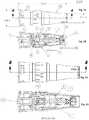
- Figures 2A, 2B, 3A, 3Billustrate a preferred embodiment of the present invention of the lower end disposable needle module 200.
- Corresponding Part Numbersare as follows: ITEM NO. DESCRIPTION 1 Housing, Right 2 Yoke 3 Coupling 4 Roller 5 M1X4 DOWEL PIN W/ SPHERICAL ENDS 6 Bell Crank 7 Connecting Rod 8 Housing, Left 9 Lock Spring 10 Slider 11 Bayonet Cup 12 Detent 13 Needle Cup 14 Needle Core 15 Needle 16 Depth Cup 17 Bellows 18 Silicone Fluid 19 Dowel Pin, 5mm long x 2 mm dia 20 Dowel Pin, 8 mm long x 1.5 mm dia 21 UV Cure Glue
- the general mechanism for moving the needles 15employs a yoke 2 and a bell crank 6 with slotted ends to drive a connecting rod 7.
- the needles 15are embedded in needle cup 13.
- a bellow 17keeps the disposable lower end needle module 200 sealed away from action of the connecting rod 7.
- the action of the connecting rod 7is coupled to needle cup 13 that reciprocates up and down so needles 15 can penetrate the skin.
- Detents 12 in the depth cup 16allow a user to feel a click in resistance and adjust the depth that the needles 15 will move from 0.0 to 2.5 mm. To engage the disposable lower end needle module 200 to the pen upper end 100 they are pushed axially together and then twisted to lock in place.
- a recharging cradle 300is disclosed to safely hold and charge the pen upper end 100 battery 16 ( Fig. 1 ) comprising the following: ITEM NO. DESCRIPTION 1 Charger, Bottom 2 Charger, Top 3 Bracket 4 SHCS 6-32 5 THREAD FORMING SCREW, 4-20 6 THREAD FORMING SCREW, 4-20 7 Spacer 8 Bumper 9 Label 10 PCBA Cable Subasm
- the battery 16( Fig. 1 ) is sealed inside the upper end 100.
- the PCBA Assem 18( Fig.1 ) is in close proximity to PCBA cable subasm 10 ( Fig. 4, 4A ) so that when current is applied the battery 16 can be charged through inductive charging.
- Thisis a safety feature because neither the recharging cradle 300 nor the upper end 200 are opened up and plugged in to each other.
- the upper end 100 and recharging cradle 300can be easily cleaned with ethanol wipes between charging or sterilized by other chemical treatment.
- the cradleis designed to safely hold the pen upper end 100 during charging and storage.
- a collagen stimulating devicewhich utilizes a single handed operable needle module connection system, including needle(s) 15 which insert into the dermis layer of the skin to allow for stimulation of collagen growth.
- the collagen stimulating devicein the form of a reciprocating shaft device, consists of an upper end 100 and a lower end disposable needle module 200.
- the upper end 100is a durable assembly; while the lower end disposable needle module 200 is disposable.
- Inside the lower end disposable needle module 200is a needle cup 13. When the needle cup 13 is extended, the needle(s) 15 will protrude from the lower end disposable needle module 200 by the reciprocating connecting rod 7.
- the lower end disposable needle module 200will allow for increased safety, through a lowered chance of cross-contamination and single use application.
- the lower end disposable needle module 200is where the reciprocating connecting rod 7 is applied to a workpiece, as for example, when used, a needle is applied to the skin of the recipient (not shown).
- the upper end 100is the opposite end from the lower end disposable needle module 200 reciprocating connecting rod 7.
- a shaft assemblyConcentrically within the reciprocating shaft device is a shaft assembly which has a circular cross section.
- the shaft assemblyhas two sections, namely an upper section, and a lower section.
- the upper sectionis located toward the upper end of the reciprocating shaft device and the lower section is located toward the lower end of the reciprocating shaft device.
- the lower section of the shaft assemblycontains needles which when the shaft assembly is released may pierce the epidermal layer of human skin, thereby stimulating the release of collagen.
- the needle(s) 15may be injected into the skin, by way of numerous embodiments, which shall be detailed, hereinafter.
- a coil assemblyis mounted symmetrically about the shaft assembly toward the upper end of the reciprocating shaft device.
- the coil assemblyincludes a spring located within an inner housing.
- the coilencases nearly all of the upper section of the shaft assembly and a small part of the lower section of the shaft assembly adjacent to the upper section.
- the needle(s) 15 on the shaft assemblymay either be in rows, or concentric circles or overlapping to create uniform stimulation of the skin.
- the lower end disposable needle module 200converts the rotary motion from the upper end 100 into reciprocating motion for the movement of needles 15 that create micro-channels in the skin.
- This mechanical injury of the skinprompts the skin to heal itself and generate collagen, etc.
- This mechanismemploys a scotch yoke 2 and a bell crank 6 with slotted ends to drive a connecting rod 7.
- the motionis 2.75 mm total translation per cycle. This allows a needle cup 13 to create 1400 holes per second at a speed of 7000 rpm.
- the motor 15( Fig. 1 ) is capable of oscillating needle(s) 15 ( Fig. 2A,2B,3A,3B ) at between 1000-10,000 rpm.
- More needle(s) 15 and/or increased speedwill permit the generation of more micro-channels per second. Other forms of translating rotation into reciprocation may be used.
- This novel featuremakes the pen more reliable and also prevents other disposables from interacting with the upper end.
- the coupling 3rotates and drives the eccentric roller 4. This action causes the yoke 2 to oscillate back and forth in a linear motion.
- the bell crank 6multiplies this motion and redirects motion to oscillate the connecting rod 7, which is coupled to the needle cup 13, needle core 14 and needle(s) 15. So the needle(s) reciprocate in and out of the depth cup 16 and may penetrate the patient's skin when the depth cup 16 is adjusted to expose the needles 15.
- Dowel pins 5, 19, 20facilitate the conversion of rotary motion to linear reciprocation motion.
- the high speed movement of the yoke 2 and roller 4 against the housing left 8 and housing right 1is facilitated by the presence of lubricant silicone fluid 18.
- the depth adjustment for the needle(s) 15is located on the lower end disposable needle module 200 - not on the upper end 100.
- This means the depth cup 16can be turned from its initial position of 0 depth through 11 distinct depth settings, each 0.25 mm deeper, until it reaches a limit of 2.5 mm.
- the detent 12gives sensory feedback to the user and effectively locks the position, detent 12 also interferes with the depth cup 16 at the 0 mm depth to prevent any further depth inward setting less than 0.0mm.
- the depth cup 16 back elementprevents adjusting the depth greater than 2.5 mm.
- the depth cup 16has markings and numbers to identify the depth setting. Adjustment of the depth on the lower end disposable needle module 200 instead of the upper end 100 means only one hand of the user is contaminated. The other hand is on a protective sheath over the upper end 100.
- the usermay twist the depth cup 16 relative to the bayonet cup 11 to reveal more of the needle(s) 15 length.
- This depth adjustmentis facilitated by three items.
- First the depth cup 16may not be adjusted below zero (0) where the depth cup 16 is trapped by the retention feature on the housing left 8. Also the depth cup 16 may not go above the highest setting of 2.5 where the depth cup 16 stops turning against the bayonet cup 11.
- the depth cup 16has slots that engage the flexible detent 12 to enable intermediate depth settings.
- the thread pitch of the depth cup 16is such that axial force on the tip is not great enough to cause rotation of the depth cup 16 and alter the setting.
- the lower end disposable needle module 200has a tight fitting bellows 17 that is sealed around connecting rod 7.
- the inner cup back (16)is effectively sealed against the pen bayonet lock.
- the penhas an integral rotary seal (15) that serves as an extra barrier during treatment, but the primary barrier when the disposable lower end is removed and the pen is still present in the treatment arena.
- the inner cup back element (16)has a raised feature to capture the protective sheath and the protective sheath keeps the pen contaminant free during use.
- the bellows 17prevent migration of gels used during treatment to the mechanism and also prevents migration of blood to the pen.
- the presence of glue 21aids in securing the needles 15 to the needle core 14 to avoid any needles being retained in the patient's skin during treatment.
- Alternative embodimentsmay include differing needle shapes, such as a star or x- shape reduce the cross- section of the needle point over a certain depth of penetration into the dermis.
- a further alternative embodimentmay include a drug delivery system, in the form of an internal reservoir or an attached cartridge, along with a hypodermic needle from which to inject a drug or skin formulation.
- the devicecontains a depth sensor and alarm to notify a user when the needle(s) have reached the appropriate depth.
- the devicecontains an actuator to control the speed, depth and dwell time of needle penetration.
- the devicewill contain a processor and communication module, such as a Wi- Fi, radio, or blue tooth transmitter, allowing one- or two- way transmission of data to a software application for data analysis, and prescription purposes; dosage, time, depth depending on the medication, tracking.
- a processor and communication modulesuch as a Wi- Fi, radio, or blue tooth transmitter, allowing one- or two- way transmission of data to a software application for data analysis, and prescription purposes; dosage, time, depth depending on the medication, tracking.
Landscapes
- Health & Medical Sciences (AREA)
- Engineering & Computer Science (AREA)
- Life Sciences & Earth Sciences (AREA)
- Public Health (AREA)
- Veterinary Medicine (AREA)
- Animal Behavior & Ethology (AREA)
- General Health & Medical Sciences (AREA)
- Biomedical Technology (AREA)
- Heart & Thoracic Surgery (AREA)
- Anesthesiology (AREA)
- Hematology (AREA)
- Vascular Medicine (AREA)
- Medical Informatics (AREA)
- Surgery (AREA)
- Rehabilitation Therapy (AREA)
- Dermatology (AREA)
- Nuclear Medicine, Radiotherapy & Molecular Imaging (AREA)
- Molecular Biology (AREA)
- Epidemiology (AREA)
- Pain & Pain Management (AREA)
- Physical Education & Sports Medicine (AREA)
- Mechanical Engineering (AREA)
- Infusion, Injection, And Reservoir Apparatuses (AREA)
- Percussion Or Vibration Massage (AREA)
- Finger-Pressure Massage (AREA)
- Surgical Instruments (AREA)
- Media Introduction/Drainage Providing Device (AREA)
- Electrotherapy Devices (AREA)
Description
- This application claims priority to
US provisional application number 62/146,939 filed April 13, 2015 - This invention relates to the delivery of a needle through the epidermis and into the dermis. Collagen growth is stimulated by injury to the skin. Uncontrolled injury of the dermis can trigger collagen over stimulation and create scar tissue and keloids. Controlled micro-injury to the dermis causes collagen to be produced in a relatively controlled manner to restore elasticity to older skin. Additionally, in the cases of scar tissue and keloids micro-injury can cause remodeling of the tissue to reduce the overall appearance of the scar.
- The global demand for medical aesthetic devices has been estimated to be 4.8 billion dollars. The growth for medical aesthetic devices is expected to grow 12.2% year over year through at least 2018.
- Numerous examples of medical aesthetic devices exist in the prior art.
- J Biophotonics. 2014 Nov;7(I I-12):914-25. doi: 10.1002/jbio.201300124. Epub 2013 Dec 11. Title: In vivo non-invasive monitoring of collagen remodelling by two-photon microscopy after micro-ablative fractional laser resurfacing. Authors: Cicchi RI, Kapsokalyvas D, Troiano M, Campolmi P, Morini C, Massi D, Cannarozzo G, Lotti T, Pavone FS.
- Abstract: Non-linear optical microscopy is becoming popular as a non-invasive in vivo imaging modality in dermatology. In this study, combined TPF and SHG microscopy were used to monitor collagen remodelling in vivo after micro-ablative fractional laser resurfacing. Papillary dermis of living subjects, covering a wide age range, was imaged immediately before and forty days after treatment. A qualitative visual examination of acquired images demonstrated an age-dependent remodelling effect on collagen. Additional quantitative analysis of new collagen production was performed by means of two image analysis methods. A higher increase in SHG to TPF ratio, corresponding to a stronger treatment effectiveness, was found in older subjects, whereas the effect was found to be negligible in young, and minimal in middle age subjects. Analysis of collagen images also showed a dependence of the treatment effectiveness with age but with controversial results. While the diagnostic potential of in vivo multiphoton microscopy has already been demonstrated for skin cancer and other skin diseases, here we first successfully explore its potential use for a non-invasive follow-up of a laser-based treatment.
- J Cutan Aesthet Surg. 2013 Jul;6(3):144-7. doi: 10.4103/0974-2077.118408. Title: Chemical reconstruction of skin scars therapy using 100% trichloroacetic Acid in the treatment of atrophic facial post varicella scars: a pilot study. Authors: Agarwal N1, Mittal A, Kuldeep C, Gupta LK, Khare AK, Mehta S.
- Abstract: Chickenpox (varicella) is a common viral disease caused by Varicella zoster virus. Facial atrophic scars after varicella infection are not uncommon and pose a cosmetic problem. Like atrophic scars of other aetiologies, they are a difficult condition to treat. There are not enough references in the literature regarding efficient treatment of post varicella scars. High strength Trichloroacetic acid (TCA), which is known to cause dermal collagen remodelling, was used to treat varicella scars in the present study. The study was undertaken to assess the efficiency of Chemical Reconstruction of Skin Scars (CROSS) technique using 100% TCA in the treatment of atrophic facial post varicella scars. MATERIALS AND METHODS: A total of 16 patients with atrophic facial post varicella scars were treated by focal application of 100% TCA solution by pressing down upon the scar surface by a toothpick (CROSS technique). Total 4 sittings were given at 2 weekly intervals and the results evaluated after 3 months of follow-up. Statistical analysis was carried out using Fischer's exact t-test. RESULTS: All of the 13 patients who completed the study showed good clinical improvement, with 69% patients grading the response as excellent (>75%) improvement, whereas the rest 31% patients reporting good (51-75%) improvement. No significant complications were seen in any patient. CONCLUSIONS: CROSS technique using 100% TCA is a safe, cheap and effective therapy for the treatment of post varicella scars.
- J Eur Acad Dermatol Venereol. 2007 Aug;21(7):877-90. Title: Pulsed dye laser: what's new in non-vascular lesions? Authors: Karsai S1, Roos S, Hammes S, Raulin C.
- Abstract: In dermatology, the pulsed dye laser (PDL) is the therapeutic instrument of choice for treating most superficial cutaneous vascular lesions. In addition, clinical experience over the last decade allowed us to treat patients with an ever increasing number of non-vascular indications. The purpose of this report is to summarize and critically appraise the scientific evidence that support the role of PDL in treating non-vascular skin lesions.
- METHODS: A literature-based study has been conducted, including the review of publications over the period January 1995 to December 2006, using the Medline Database. We also included our own experience in managing non-vascular lesions with the PDL. Four sets of preoperative and postoperative photos are presented.
- RESULTS: For viral skin lesions, PDL proved to be an alternative to other therapy options. This applies particularly to periungual warts and mollusca contagiosa. The mechanism of PDL with inflammatory dermatoses has not yet been elucidated. The effect seems to be better if there is a vascular component to the disease. With most of these indications (such as psoriasis and acne), PDL currently plays a rather minor or complementary role. Regarding collagen remodelling (hypertrophic scars, keloids, stretch marks, and skin rejuvenation), the question of whether a therapy makes sense or not has to be decided from case to case.
- CONCLUSION: With PDL, it is possible to achieve good results with numerous, partly less well-known indications (i.e. lupus erythematosus). With other diseases, PDL has so far been considered to be a complementary therapy method or to be in an experimental state.
- J Cosmet Laser Ther. 2003 Dec;5(3-4):201-3. Title: ED2000: 585 nm collagen remodelling pulsed dye laser. Author: Michel JL1.
- Abstract: The wavelength of 585nm corresponds to an absorption peak of haemoglobin. The heating effect in these skin layers triggers the release of various growth factors that stimulate collagen remodelling and tightening. We report our experience with a 585nm collagen remodelling, double flashlamp excited pumped dye laser was used (ED2000, Deka MELA, Calenzano, Italy),
spot size 5 mm, energy density (fluence J/cm(2)) from 2 to 4 J/cm(2), emission modality (repetition rate) at 0.5 Hz, with a short pulse duration of 250 microsec. The efficiency of 585 nm collagen remodelling pulsed dye laser is controversial in only one session. It is probably reasonable to inform patients that 3-4 treatment sessions are necessary, and that 10% of the patients have no response to nonablative photorejuvenation. Because of its low fluence and its shorter pulse duration, the 585 nm collagen remodelling pulsed dye laser has limited efficacy for the treatment of port wine stains. However, it may offer patients with erythematous, raised or hypertrophic acne scars or striae distensae a permanent cosmetic solution. This laser is safe and effective in the treatment of surgical scars starting as soon as possible, on the day of suture removal if possible. We found that 96.3% of molluscum contagiosum healed after the first treatment, the other 3.7% after the second. - Lasers Med Sci. 2003;18(2):104-11. Title: Non-ablative facial skin photorejuvenation with an intense pulsed light system and adjunctive epidermal care. Authors: Trelles MA1, Allones I, Velez M. Abstract: Laser skin resurfacing is popular, but the appearance of the face during healing is unpleasant. Non-ablative photorejuvenation with intense pulsed light (IPL) has been reported as being successful but with varied results. In this study we sought the possibility of enhancing the clinical effects with adjunctive epidermal care. Twenty-five women aged from 32 to 68, skin types I-IV, with a variety of wrinkle types and other conditions associated with photoaged skin, were treated with IPL according to our parameters over six sessions coupled with an adjunctive pretreatment micropeel and applications of nutritive and antipigmenting creams. Macroscopic and histological assessments were performed. At
weeks 4 and 8 fair to good satisfaction was noted in 17 and 19 patients, and poor satisfaction in 8 and 6 patients, respectively. The histology showed good dermal collagen remodelling in all cases, with a reduction in elastosis. The results of IPL photorejuvenation can be enhanced, as our trials showed. The good patient satisfaction obtained was clearly demonstrated in the histologies and evaluations throughout the study. - J Cell Physiol. 1994 Apr;159(1):161-75. Title: Dependence of collagen remodelling on alpha-smooth muscle actin expression by fibroblasts. Author: Arora PD1, McCulloch CA.
- Abstract: To study the relation between expression of the putative myofibroblast marker alpha-smooth muscle actin and the remodelling of extracellular matrix, immunocytochemical, gel electrophoresis, and collagen gel contraction studies were performed on two human fibroblast subtypes. Double immunolabelling for total actins and alpha-smooth muscle (sm) actin as well as affinity labelling of filamentous and monomeric actins in gingival fibroblasts demonstrated that alpha-sm was colocalized in stress fibres and in regions with high levels of monomeric actin throughout the cytoplasm. alpha-sm comprised up to 14% of total cellular actin as assessed by 2D gel electrophoresis. Thirteen different gingival and seven different periodontal ligament fibroblast lines constitutively expressed on alpha-sm actin. These cells exhibited up to 60% inter-line variations of fluorescence due to alpha-sm actin and up to 70% and 45% inter-line variation in the rate of collagen gel contraction. Quantitative, single cell fluorimetry of alpha-sm actin immunoreactivity demonstrated a linear relation between gel contraction and alpha-sm actin (correlation coefficients of 0.71 for gingival and 0.61 for periodontal ligament cells), but there was no detectable relationship between total actin content and gel contraction. In contrast, flow cytometry demonstrated that 99% of the total gated cells from cell lines exhibiting rapid gel contraction showed alpha-sm actin staining above background fluorescence as compared to only 35% of cells with slow rates of gel contraction. Contracting collagen gels stained with FITC-phalloidin showed cells with well-developed stress fibres that were progressively more compact and elongated during the time of maximal gel contraction. To examine the dependence of gel contraction on assembly of monomeric actin into actin filaments, cells were electroporated in the presence of phalloidin or cytochalasin D. Collagen gels exhibited up to 100% inhibition of gel contraction that was dose-dependent. Gel contraction was inhibited 93% by electroinjection of cells with alpha-sm actin antibody prior to incubation, but the antibody did not inhibit actin assembly after attachment and spreading on substrates. These data indicate that gel contraction is dependent on alpha-sm actin expression and that alpha-sm actin is a functional marker for a fibroblast subtype that rapidly remodels the extracellular matrix.
- US Publication No.
US2009/0312691 from Kim et al. , discloses "a micro needle roller assembly comprising a roller head including an external cylindrical member having a plurality of micro needles mounted on a surface thereof and an internal member placed in the external member and supported to the external member by supporting piece; and a handling member coupled to the internal member for rotating the internal member of the roller head; the micro needles, the external cylindrical member and the internal member being made of polymer resin." - US Patent Publication No.
US2019/0314048 to Knowlton discloses a "new minimally invasive surgical approach is proposed that contemplates a method and apparatus for tightening lax skin without visible scarring via a device in various surgical procedures such as plastic surgery procedures. In some embodiments, the device is a single use disposable instrument. This approach circumvents surgically related scarring and the clinical variability of electromagnetic heating of the skin and performs small multiple pixilated resections of skin as a minimally invasive alternative to large Plastic surgical resections of skin. This approach can also be employed in areas of the body that are currently off limits to plastic surgery due to the visibility of the surgical scar. In addition, the approach can perform a skin grafting operation by harvesting the transected incisions of skin from a tissue site of a donor onto a skin defect site of a recipient with reduced scarring of the patient's donor site." - US Patent Publication No.
US2013/0102956 to Hertzog discloses a "hollow needle for attachment to a syringe, through which a liquid can be delivered to the stratum granulosum and/or beneath the epidermis, preferably to an area consisting from the stratum granulosum (included) to reticular dermis (included) and more preferably beneath the papillary dermis during a cosmetic procedure, the needle comprising a distal tip and including a lateral aperture adjacent to the distal tip, wherein the liquid exits the needle via the lateral aperture, and wherein the needle is flexible. Apparatus comprising a needle of the invention and a syringe, and a method of use thereof, is also provided." - US Patent Publication No.
US2013/0345616 to Chang discloses a "device and methods for increasing the permeability of the skin's surface to fluid and/or drug delivery is described. The device comprises an abrasive media to remove the outer layer of the stratum corneum, while at the same time applying an electric current that stimulates the skin under the stratum corneum, and delivers fluids from a supply reservoir. The device may also have a vacuum function which evacuates fluid and skin debris from the surface of the skin and delivers the evacuated fluid and skin debris to a waste (or collection) container." - US Patent Publication No.
US2014/0128685 to Na discloses "methods and systems for dermatologic treatments" including precise delivery of needles to the skin. - US Patent Publication No.
US2014/0276248 to Hall et al. , discloses a "system for delivering light and/or ultrasound across a skin surface is provided. The system includes a device having a layered structure comprising one or both of a light source and an ultrasonic transducer. The light source comprises a flexible light emitter layer electrically coupled to a first conductive layer and a second conductive layer, wherein at least one of the first and second conductive layers is transparent. The ultrasonic transducer comprises a flexible ultrasound emitter layer electrically coupled to a third conductive layer and a fourth conductive layer. The system also includes one or more sensors in contact with the skin surface and a controller electrically coupled to the device and the sensor. The controller is operable to receive sensor data from the sensor and dynamically control the device in response to the received sensor data." - US Patent Publication No.
US2013/0331879 to Nagao et al. , discloses a "puncture needle cartridge which can prevent a used lancet from being reused. A puncture needle cartridge includes a puncture needle holder configured to be cylindrical, placed on an outer circumferential surface of a lancet body, and provided with an opening through which a puncture needle is allowed to protrude, and a protective cap adapted to cover and protect the opening and configured to be separable from the puncture needle holder. The protective cap includes a base adapted to cover the opening when the protective cap is joined and a pair of raised walls which protrude from the base toward the puncture needle holder and whose tip portions are placed facing each other. Tip portions of the raised walls pinch the puncture needle holder by spreading against elastic deformation when the protective cap is joined to the puncture needle holder, and when the protective cap is separated from the puncture needle holder, a space between the tip portions becomes smaller than outside diameter of the puncture needle holder due to elastic deformation." - US Patent Publication No.
US2011/0270364 to Kreindel et al. , discloses an "applicator for skin treatment having one or more RF electrodes. An article is located between the electrodes, such as a roller or flexible belt containing one or more protruding pins electrically isolated from the RF electrodes. The invention also provides a system for skin treatment comprising the applicator of the invention and a control unit. The invention further provides a method of treating skin disorders in which a section of the skin is heated while, essentially simultaneously, piercing one or more holes in the heated section of the skin. The method of the invention may be used, for example, in collagen remodeling." - US Patent Publication No.
US2010/0249772 to Mehta et al. , discloses "a system and method for percutaneous energy delivery in an effective, manner using one or more probes to effect a cosmetic improvement in tissue." - US Patent Publication No.
US2009/0137945 to Marquez discloses a "device for creating a plurality of small wounds in a patient's skin and introducing topically-applied substances therein is disclosed. The device comprises a rigid plate that has a top side, a bottom side, and at least one peripheral edge that connects the top and bottom sides. The device further includes a tool attachment means fixed with the top side of
the plate and adapted to fix the device to a motorized tool that oscillates reciprocally back and forth along the longitudinal axis of the plate. A plurality of needles project generally orthogonally away from the bottom side of the plate. In use, the plate is fixed with the tool and the tool activated. The bottom side of the plate is then applied to the skin of the patient such that each needle repeatedly pierces same to create the plurality of small wounds therein. When the substance is applied to the skin first, each needle draws a portion of the substance into the skin with each oscillation of the tool." EP2377475 relates to apparatus for treating tennis elbow including a holder part with penetration means attached thereto.US2014/0303555 relates apparatus comprising a dispense interface with lockout element. The lockout element comprises at least one spring component removeably maintained in a respective first position. Each spring component moves into a respective second position which is configured to prevent said dispense interface from being reattached to a drug delivery device.US2010/0023003 relates to a skin rejuvenation resurfacing device and method of use comprising an oscillating, reciprocating high speed, needle-based device and its related procedure for inducing mechanical trauma to an area of the skin to be treated.US2012/0041374 relates to a needle unit and dermatological liquid injection apparatus including a body unit and driving device, a cam member rotated by the driving device and a connecting member reciprocally driven by the cam member, a needle unit detachably mounted to a front end of the body unit; and a rubber member installed to the needle unit, for blocking blood and liquid mixture which are discharged from a skin of patient and flow into the needle unit, from flowing to the body unit during a medical procedure.US2008/0039806 relates to micro needles and method of manufacture thereof, the micro-needle protrudes from a support member. The needle body portion has at least one side opening communicating with said inner lumen.- The invention is defined in
claim 1. Preferred embodiments are defined in the dependent claims. The exemplary embodiment of the present invention addresses safety issues with respect to an operator being able to load and unload needles safely with one hand while maintaining the other hand free during the procedure. Accordingly, an aspect of the present invention is to provide a separable module for housing needles. The present invention provides an apparatus and system to reduce cross-contamination between patients. Accordingly, an aspect of the present disclosure is to provide a control and reporting means so that a needle module may only be used one time or controlled by external means such as a preset time, RFID communication, or physical impairment. The present disclosure provides a needle to reduce the overall amount of damage to the dermis than by commonly used round needle tips. - Accordingly, an aspect of the disclosure is to provide an X-shaped needle to reduce the cross-section of the needle point over a certain depth of penetration into the dermis. The present disclosure provides for a sensing system to determine the needle point position relative to the epidermis to dermis junction.
- Accordingly, an aspect of the disclosure is to provide a sensing mechanism and a microprocessor to modulate the depth, frequency, and power of needle movement during operation.
Fig. 1 shows an exploded view of a preferred embodiment of a single handed operable needle module upper end.Fig. 2A shows a preferred embodiment of a single handed operable needle module connection system with a lower enddisposable needle 200.Fig. 2B shows a cut away of the preferred embodiment of a single handed operable needle module connection system with a lower enddisposable needle 200.Fig. 3A shows a preferred embodiment of a single handed operable needle module connection system with an upper and lower end connected.Fig. 3B shows a cut away of the preferred embodiment of a single handed operable needle module connection system with an upper and lower end connected.Fig. 4A shows a preferred embodiment of a battery recharging cradle.Fig. 4B shows a cut away of the preferred embodiment of a battery recharging cradle.- Referring to
Fig. 1 an exploded view of the upper end of the pen system is comprised of the following parts:ITEM NO. DESCRIPTION 1 Pen Tip 2 Bearing 5x13x4 3 Bearing Spacer 4 Pen Shaft 5 Wave Spring 6 Wave Spring Adapter 7 Spiral Snap Ring 8 Motor Mounting Cup 9 Spider Coupling 10 Motor Shaft Coupling 11 Snap Ring 12 Rotary Seal 13 M2x0.4 x 2.5 LG SET SCREW 14 M1.6x0.35 x 2.5 LG SET SCREW 15 DC Motor 16 Battery, Rechargeable Li, 3.7V, 2.6 Ah 17 Battery Bracket 18 PCB Assem 19 M1.6X0.35 PH SCREW 20 Oring 22 0-80 screw 23 PCBA Bracket 24 Case Handle, Left 25 Case Handle, Right 26 Cowl, Front 27 Cowl, Rear 28 Case Handle Overlay 29 Label 30 Battery Compression Strip 31 Threadlocker 32 Epoxy 33 Flat Black Paint 34 Thermal Gel 35 Housing Stabilizer 36 Sensor Eye Hold down 37 Electrical Insulation Tape - The DC Motor 15 (
Fig. 1 ) provides rotational movement to the lower end disposable needle module 200 (Fig. 2 ). Theupper end 100 ofFig. 1 is completely sealed from the lower enddisposable needle module 200. Figures 2A, 2B, 3A, 3B illustrate a preferred embodiment of the present invention of the lower enddisposable needle module 200. Corresponding Part Numbers are as follows:ITEM NO. DESCRIPTION 1 Housing, Right 2 Yoke 3 Coupling 4 Roller 5 M1X4 DOWEL PIN W/ SPHERICAL ENDS 6 Bell Crank 7 Connecting Rod 8 Housing, Left 9 Lock Spring 10 Slider 11 Bayonet Cup 12 Detent 13 Needle Cup 14 Needle Core 15 Needle 16 Depth Cup 17 Bellows 18 Silicone Fluid 19 Dowel Pin, 5mm long x 2 mm dia 20 Dowel Pin, 8 mm long x 1.5 mm dia 21 UV Cure Glue - The general mechanism for moving the
needles 15 employs a yoke 2 and a bell crank 6 with slotted ends to drive a connectingrod 7. Theneedles 15 are embedded inneedle cup 13. Abellow 17 keeps the disposable lowerend needle module 200 sealed away from action of the connectingrod 7. The action of the connectingrod 7 is coupled toneedle cup 13 that reciprocates up and down so needles 15 can penetrate the skin.Detents 12 in thedepth cup 16 allow a user to feel a click in resistance and adjust the depth that theneedles 15 will move from 0.0 to 2.5 mm. To engage the disposable lowerend needle module 200 to the penupper end 100 they are pushed axially together and then twisted to lock in place. - Referring to
Figs. 4A, 4B a rechargingcradle 300 is disclosed to safely hold and charge the penupper end 100 battery 16 (Fig. 1 ) comprising the following:ITEM NO. DESCRIPTION 1 Charger, Bottom 2 Charger, Top 3 Bracket 4 SHCS 6-32 5 THREAD FORMING SCREW, 4-20 6 THREAD FORMING SCREW, 4-20 7 Spacer 8 Bumper 9 Label 10 PCBA Cable Subasm - The battery 16 (
Fig. 1 ) is sealed inside theupper end 100. When theupper end 100 is placed on to the rechargingcradle 300 charger top 2 (Fig.4, 4A ) the PCBA Assem 18 (Fig.1 ) is in close proximity to PCBA cable subasm 10 (Fig. 4, 4A ) so that when current is applied thebattery 16 can be charged through inductive charging. This is a safety feature because neither the rechargingcradle 300 nor theupper end 200 are opened up and plugged in to each other. Theupper end 100 and rechargingcradle 300 can be easily cleaned with ethanol wipes between charging or sterilized by other chemical treatment. The cradle is designed to safely hold the penupper end 100 during charging and storage. - According to one aspect of an exemplary embodiment of the present invention, depicting a collagen stimulating device which utilizes a single handed operable needle module connection system, including needle(s) 15 which insert into the dermis layer of the skin to allow for stimulation of collagen growth. The collagen stimulating device, in the form of a reciprocating shaft device, consists of an
upper end 100 and a lower enddisposable needle module 200. Theupper end 100 is a durable assembly; while the lower enddisposable needle module 200 is disposable. Inside the lower enddisposable needle module 200 is aneedle cup 13. When theneedle cup 13 is extended, the needle(s) 15 will protrude from the lower enddisposable needle module 200 by thereciprocating connecting rod 7. The lower enddisposable needle module 200, will allow for increased safety, through a lowered chance of cross-contamination and single use application. - The lower end
disposable needle module 200 is where thereciprocating connecting rod 7 is applied to a workpiece, as for example, when used, a needle is applied to the skin of the recipient (not shown). Theupper end 100 is the opposite end from the lower enddisposable needle module 200reciprocating connecting rod 7. When the lower enddisposable needle module 200reciprocating connecting rod 7 is held against the workpiece, such as human skin, the needle(s) 15 will penetrate the epidermis and to the epidermis, causing the stimulation of collagen. - Concentrically within the reciprocating shaft device is a shaft assembly which has a circular cross section. The shaft assembly has two sections, namely an upper section, and a lower section. The upper section is located toward the upper end of the reciprocating shaft device and the lower section is located toward the lower end of the reciprocating shaft device. The lower section of the shaft assembly contains needles which when the shaft assembly is released may pierce the epidermal layer of human skin, thereby stimulating the release of collagen. The needle(s) 15 may be injected into the skin, by way of numerous embodiments, which shall be detailed, hereinafter.
- A coil assembly is mounted symmetrically about the shaft assembly toward the upper end of the reciprocating shaft device. The coil assembly includes a spring located within an inner housing. The coil encases nearly all of the upper section of the shaft assembly and a small part of the lower section of the shaft assembly adjacent to the upper section. The needle(s) 15 on the shaft assembly may either be in rows, or concentric circles or overlapping to create uniform stimulation of the skin.
- Referring to
Figs. 1-3B , the lower enddisposable needle module 200 converts the rotary motion from theupper end 100 into reciprocating motion for the movement ofneedles 15 that create micro-channels in the skin. This mechanical injury of the skin prompts the skin to heal itself and generate collagen, etc. This mechanism employs a scotch yoke 2 and a bell crank 6 with slotted ends to drive a connectingrod 7. The motion is 2.75 mm total translation per cycle. This allows aneedle cup 13 to create 1400 holes per second at a speed of 7000 rpm. The motor 15 (Fig. 1 ) is capable of oscillating needle(s) 15 (Fig. 2A,2B,3A,3B ) at between 1000-10,000 rpm. More needle(s) 15 and/or increased speed will permit the generation of more micro-channels per second. Other forms of translating rotation into reciprocation may be used. This novel feature makes the pen more reliable and also prevents other disposables from interacting with the upper end. Thecoupling 3 rotates and drives the eccentric roller 4. This action causes the yoke 2 to oscillate back and forth in a linear motion. Thebell crank 6 multiplies this motion and redirects motion to oscillate the connectingrod 7, which is coupled to theneedle cup 13,needle core 14 and needle(s) 15. So the needle(s) reciprocate in and out of thedepth cup 16 and may penetrate the patient's skin when thedepth cup 16 is adjusted to expose theneedles 15. Dowel pins 5, 19, 20 facilitate the conversion of rotary motion to linear reciprocation motion. The high speed movement of the yoke 2 and roller 4 against the housing left 8 andhousing right 1 is facilitated by the presence of lubricant silicone fluid 18. - In order for the user to attach the lower end
disposable needle module 200 to the upper end, they must line up a d-shaped disposable coupling of the lower enddisposable needle module 200 with a corresponding d-shaped shaft on theupper end 100. The user must align the d-shaped shaft of theupper end 100 with the d-shaped opening of the coupling 3 (Fig. 2A, 2B, 3A, 3B ). Then push the lower enddisposable needle module 200 onto theupper end 100 and rotate the bayonet cup 11 to engage the male lugs of theupper end 100. This action pushes the slider 10 (Fig. 2A, 2B, 3A, 3B ) forward and lets the lock spring 9 drop onto the pen shaft. Further rotation by the user fully engages the bayonet cup 11 onto theupper end 100. There is only one way to attach the lower enddisposable needle module 200 to theupper end 100 to ensure the rotational orientation of the lower enddisposable needle module 200 andupper end 100 for keying the low point of the reciprocation motion. By sliding the upper end pen tip 1 (Fig. 1 ) into lower end disposable needle module 200 (Figs. 2A, 2B, 3A, 3B ), the home position of the lower enddisposable needle module 200 reciprocation low point is known and the pen software will turn the lower enddisposable needle module 200 end so the low point of reciprocation is located during power shutdown. This brings the needle(s) 15 inside the depth of thedepth cup 16 by at least 0.25 mm at all times (more if thedepth cup 16 is set to a lower depth). Also, this arrangement ensures the needle(s) 15 can only be set to penetrate the skin by a maximum of 2.5 mm. Furthermore, when the pen tip 1 (Fig. 1 ) is inserted into the bayonet cup 11 is pushed along a locking spring 9 and into the lower enddisposable needle module 200. This action loads the locking spring 9 and upon removal of the lower enddisposable needle module 200, the locking spring 9 is free to bend upwards and block the reinsertion of the lower enddisposable needle module 200. This makes the lower end disposable needle module 200 a single use device. - The depth adjustment for the needle(s) 15 is located on the lower end disposable needle module 200 - not on the
upper end 100. This means thedepth cup 16 can be turned from its initial position of 0 depth through 11 distinct depth settings, each 0.25 mm deeper, until it reaches a limit of 2.5 mm. Thedetent 12 gives sensory feedback to the user and effectively locks the position,detent 12 also interferes with thedepth cup 16 at the 0 mm depth to prevent any further depth inward setting less than 0.0mm. For the 2.5 mm depth thedepth cup 16 back element prevents adjusting the depth greater than 2.5 mm. Thedepth cup 16 has markings and numbers to identify the depth setting. Adjustment of the depth on the lower enddisposable needle module 200 instead of theupper end 100 means only one hand of the user is contaminated. The other hand is on a protective sheath over theupper end 100. - The user may twist the
depth cup 16 relative to the bayonet cup 11 to reveal more of the needle(s) 15 length. This depth adjustment is facilitated by three items. First thedepth cup 16 may not be adjusted below zero (0) where thedepth cup 16 is trapped by the retention feature on the housing left 8. Also thedepth cup 16 may not go above the highest setting of 2.5 where thedepth cup 16 stops turning against the bayonet cup 11. For other settings thedepth cup 16 has slots that engage theflexible detent 12 to enable intermediate depth settings. The thread pitch of thedepth cup 16 is such that axial force on the tip is not great enough to cause rotation of thedepth cup 16 and alter the setting. - The blockage and elimination of fluids from the patient entering the
upper end 100 is addressed by multiple features. First the lower enddisposable needle module 200 has a tight fitting bellows 17 that is sealed around connectingrod 7. Second, the inner cup back (16) is effectively sealed against the pen bayonet lock. Third, the pen has an integral rotary seal (15) that serves as an extra barrier during treatment, but the primary barrier when the disposable lower end is removed and the pen is still present in the treatment arena. The inner cup back element (16) has a raised feature to capture the protective sheath and the protective sheath keeps the pen contaminant free during use. - The bellows 17 prevent migration of gels used during treatment to the mechanism and also prevents migration of blood to the pen. The presence of glue 21 aids in securing the
needles 15 to theneedle core 14 to avoid any needles being retained in the patient's skin during treatment. - Alternative embodiments may include differing needle shapes, such as a star or x- shape reduce the cross- section of the needle point over a certain depth of penetration into the dermis. A further alternative embodiment may include a drug delivery system, in the form of an internal reservoir or an attached cartridge, along with a hypodermic needle from which to inject a drug or skin formulation. In yet another alternative embodiment, the device contains a depth sensor and alarm to notify a user when the needle(s) have reached the appropriate depth. In yet another alternative embodiment, the device contains an actuator to control the speed, depth and dwell time of needle penetration. In yet another alternative embodiment, the device will contain a processor and communication module, such as a Wi- Fi, radio, or blue tooth transmitter, allowing one- or two- way transmission of data to a software application for data analysis, and prescription purposes; dosage, time, depth depending on the medication, tracking.
- While preferred embodiments of the invention have been illustrated, it will be obvious to those skilled in the art that various modifications and changes may be made thereto without departing from the scope of the invention as hereinafter defined in the appended claims.
Claims (14)
- A device for stimulating collagen growth in a human, the device comprising:an upper end (100) including a motor and a pen shaft;a lower end disposable needle module (200), the lower end disposable needle module (200) being removably attachable to the upper end (100) and including a lock spring (9), a coupling (3) configured to receive the pen shaft, and a connecting rod (7), the connecting rod being coupled to the motor and at least one needle (15), the motor providing a reciprocating motion to the connecting rod (7),wherein, when the lower end disposable needle module (200) is detached from the upper end (100), the lock spring (9) bends upwards to prevent the coupling (3) from receiving the pen shaft such that the lower end disposable needle module (200) cannot be re-attached to the upper end (100),wherein the coupling (3) is attached to an eccentric roller (4), the eccentric roller is coupled to a yoke (2), the yoke is coupled to a bell crank (6) and the bell crank is attached to the connecting rod, andwherein, when the motor turns the coupling (3) and the eccentric roller (4), the eccentric roller engages the yoke (2) to oscillate, the yoke oscillates the bell crank (6) and the bell crank moves the connecting rod (7) and the at least one needle (15).
- The device of claim 1 wherein the at least one needle (15) reciprocates at between 1,000-10,000 rpm.
- The device of claim 1 wherein the at least one needle depth of penetration can be adjusted from 0-2.5 mm.
- The device of claim 1 wherein the at least one needle depth of penetration can be adjusted in 0.25 mm increments.
- The device of claim 1 wherein the attachment comprises the steps of inserting the upper end tip into the lower end disposable needle module and twisting the upper end relative to the lower end disposable needle module to a locked position.
- The device of claim 1 wherein the connecting rod (7) is sealed with a bellows (17).
- The device of claims 1-6 wherein the needle (15) is X-shaped.
- The device of claim 1 further comprising a battery (16) positioned within the upper end (100).
- The device of claim 8 wherein the battery (16) is rechargeable.
- The device of claim 1 wherein the motor provides rotary motion that is converted to reciprocating motion by the eccentric roller (4), the yoke (2), and the bell crank (6).
- The device of claim 10 wherein the reciprocating motion includes a high point wherein the at least one needle (15) protrudes from the lower end disposable needle module (200) and a low point wherein the at least one needle (15) does not protrude from the lower end disposable needle module (200).
- The device of claim 11 wherein attachment of the upper end (100) to the lower end disposable needle module (200) keys the low point of the reciprocation motion.
- The device of claim 12 wherein during power shutdown of the device, software in the device returns the at least one needle to the low point.
- The device of claim 1 wherein the at least one needle (15) comprises a plurality of needles arranged in concentric circles.
Priority Applications (3)
| Application Number | Priority Date | Filing Date | Title |
|---|---|---|---|
| HRP20210151TTHRP20210151T1 (en) | 2015-04-13 | 2016-04-13 | Collagen stimulation device |
| SI201631061TSI3283041T1 (en) | 2015-04-13 | 2016-04-13 | Collagen stimulation device |
| PL16780685TPL3283041T3 (en) | 2015-04-13 | 2016-04-13 | Collagen stimulation device |
Applications Claiming Priority (2)
| Application Number | Priority Date | Filing Date | Title |
|---|---|---|---|
| US201562146939P | 2015-04-13 | 2015-04-13 | |
| PCT/US2016/027382WO2016168374A1 (en) | 2015-04-13 | 2016-04-13 | Collagen stimulation device and methods |
Publications (3)
| Publication Number | Publication Date |
|---|---|
| EP3283041A1 EP3283041A1 (en) | 2018-02-21 |
| EP3283041A4 EP3283041A4 (en) | 2018-09-05 |
| EP3283041B1true EP3283041B1 (en) | 2020-11-18 |
Family
ID=57126085
Family Applications (1)
| Application Number | Title | Priority Date | Filing Date |
|---|---|---|---|
| EP16780685.0AActiveEP3283041B1 (en) | 2015-04-13 | 2016-04-13 | Collagen stimulation device |
Country Status (15)
| Country | Link |
|---|---|
| US (1) | US10667830B2 (en) |
| EP (1) | EP3283041B1 (en) |
| JP (1) | JP6817219B2 (en) |
| KR (1) | KR20170141200A (en) |
| CN (1) | CN107427406B (en) |
| AU (1) | AU2016250163B2 (en) |
| BR (1) | BR112017022044B1 (en) |
| CA (1) | CA2982581A1 (en) |
| DK (1) | DK3283041T3 (en) |
| ES (1) | ES2844823T3 (en) |
| HR (1) | HRP20210151T1 (en) |
| PL (1) | PL3283041T3 (en) |
| PT (1) | PT3283041T (en) |
| SI (1) | SI3283041T1 (en) |
| WO (1) | WO2016168374A1 (en) |
Cited By (1)
| Publication number | Priority date | Publication date | Assignee | Title |
|---|---|---|---|---|
| WO2025114729A1 (en)* | 2023-12-01 | 2025-06-05 | 3D-Lipo Ltd | Apparatus for carrying out a microneedling procedure |
Families Citing this family (8)
| Publication number | Priority date | Publication date | Assignee | Title |
|---|---|---|---|---|
| EP3283041B1 (en)* | 2015-04-13 | 2020-11-18 | Bellus Medical, LLC | Collagen stimulation device |
| KR101869894B1 (en)* | 2017-07-27 | 2018-06-21 | 주식회사 파나시 | High-Frequency Handpiece for acne and treatment method thereof |
| CN108498295B (en)* | 2018-04-24 | 2023-12-12 | 江南大学 | Negative pressure vibration scar treatment device |
| KR102223198B1 (en)* | 2019-02-16 | 2021-03-04 | 주식회사 모스티브 | Apparatus for skin care |
| US11590332B2 (en) | 2019-04-17 | 2023-02-28 | Path Scientific, Llc | Precision microneedling device and methods of use |
| CN211024784U (en)* | 2019-08-06 | 2020-07-17 | 何坛明 | Novel waterproof construction of micropin device |
| CN113081817A (en)* | 2021-04-09 | 2021-07-09 | 周慧涛 | Traditional chinese medical science is with vibrating skin needle of changeable dial |
| WO2022247321A1 (en)* | 2021-05-22 | 2022-12-01 | 深圳市司沃康科技有限公司 | Dynamic pressure generation device and massager |
Family Cites Families (47)
| Publication number | Priority date | Publication date | Assignee | Title |
|---|---|---|---|---|
| CH396311A (en)* | 1962-07-11 | 1965-07-31 | Schneider Emil | Graver device for skin treatment |
| CN2030490U (en) | 1987-10-12 | 1989-01-11 | 陈碌 | Portable magnetotherapy apparatus for treatment of diseases |
| SE0102736D0 (en) | 2001-08-14 | 2001-08-14 | Patrick Griss | Side opened out-of-plane microneedles for microfluidic transdermal interfacing and fabrication process of side opened out-of-plane microneedles |
| GB0327136D0 (en)* | 2003-11-21 | 2003-12-24 | Nmt Group Plc | Safety needle |
| US20050203575A1 (en)* | 2004-03-15 | 2005-09-15 | Unilever Home & Personal Care Usa, Division Of Conopco, Inc. | Skin microactivation system and method |
| CN2834422Y (en) | 2005-11-14 | 2006-11-08 | 刘国学 | Tattoo pen |
| US10799285B2 (en)* | 2005-12-22 | 2020-10-13 | Inmode Ltd. | Skin rejuvenation resurfacing device and method of use |
| JP2010515469A (en)* | 2006-01-12 | 2010-05-13 | ナノパス テクノロジーズ エルティディ. | Skin surface polishing equipment |
| JP5066566B2 (en)* | 2006-07-03 | 2012-11-07 | ホナム ペトロケミカル コープ | Micro needle roller assembly |
| DE502006001900D1 (en)* | 2006-07-25 | 2008-12-04 | Mt Derm Gmbh | Device for controlled insertion into an object and method for operating the device |
| CN101842132B (en) | 2007-08-01 | 2013-06-12 | 西纳龙医药有限公司 | Method and device for collagen growth stimulation |
| US20090137945A1 (en) | 2007-11-28 | 2009-05-28 | Claire Marquez | Electro Collagen Induction Therapy Device |
| FR2926997B1 (en) | 2008-02-04 | 2012-06-29 | Bernard Hertzog | SOFT FLEXIBLE NEEDLES FOR SKIN INJECTION WITHOUT PAIN |
| KR200451858Y1 (en)* | 2008-06-30 | 2011-01-17 | (주)아모레퍼시픽 | Skin massager |
| US20100010484A1 (en)* | 2008-07-14 | 2010-01-14 | Primaeva Medical, Inc. | Devices and methods for percutaneous energy delivery |
| WO2012118293A2 (en) | 2011-03-03 | 2012-09-07 | Na Jongju | Skin care method, apparatus and system |
| KR101013581B1 (en)* | 2008-08-06 | 2011-02-14 | 라종주 | Electric skin beauty machine |
| KR101055698B1 (en) | 2008-09-25 | 2011-08-09 | 주식회사 퓨어메디 | Manufacturing method of microneedle adhesion of ultrasonic vibration skin stimulator |
| EP2345369B1 (en) | 2008-10-09 | 2013-12-04 | Panasonic Corporation | Puncture needle cartridge |
| US20100249772A1 (en) | 2009-03-26 | 2010-09-30 | Primaeva Medical, Inc. | Treatment of skin deformation |
| KR100922138B1 (en) | 2009-04-14 | 2009-10-19 | 봄텍전자 주식회사 | Skin Liquid Penetration Device |
| AU2010280361B2 (en)* | 2009-08-04 | 2015-10-08 | Pollogen Ltd. | Cosmetic skin rejuvination |
| WO2011039728A1 (en) | 2009-10-01 | 2011-04-07 | Sara Gil Almeida | Home use electric machine and system with micro needles for stimulation of collagen and elastin producing cells |
| US8900181B2 (en) | 2009-12-18 | 2014-12-02 | Srgi Holdings, Llc | Skin treatment and drug delivery device |
| NL2004558C2 (en)* | 2010-04-15 | 2011-10-18 | Lx Consult B V | DEVICE FOR TREATMENT OF A TENNISELLEBOW. |
| US9227021B2 (en)* | 2010-06-29 | 2016-01-05 | Genesis Biosystems, Inc. | Microneedle roller (MNR) infusion system |
| CN103561673A (en)* | 2010-12-13 | 2014-02-05 | 肌肉科技股份有限公司 | Method for reducing hyperdynamic facial wrinkles |
| US20190314048A1 (en) | 2010-12-17 | 2019-10-17 | Srgi Holdings, Llc | Pixel array medical devices and methods |
| MX347856B (en)* | 2011-01-28 | 2017-05-16 | Massachusetts Gen Hospital | Method and apparatus for skin resurfacing. |
| WO2012146670A1 (en)* | 2011-04-28 | 2012-11-01 | Sanofi-Aventis Deutschland Gmbh | Dispense interface with lockout element |
| KR101262222B1 (en)* | 2011-05-27 | 2013-05-15 | 이종대 | Skin irritating unit and skin massage apparatus having the same |
| CN202236856U (en) | 2011-08-09 | 2012-05-30 | 陈明秋 | Eyebrow tattooing and tattooing integrated machine |
| CN202173684U (en)* | 2011-08-26 | 2012-03-28 | 吴翠岗 | Micro-needle cosmetic instrument |
| CN202620474U (en) | 2012-04-28 | 2012-12-26 | 深圳清华大学研究院 | Portable biological active substance introduction instrument |
| US20130345661A1 (en) | 2012-06-26 | 2013-12-26 | Franklin J. Chang | Skin Treatment Device |
| JP5954011B2 (en) | 2012-07-18 | 2016-07-20 | 凸版印刷株式会社 | Microneedle penetration control device |
| CN202740626U (en)* | 2012-08-16 | 2013-02-20 | 刘汉文 | Novel micro-needle cosmetic instrument |
| CA2906787C (en) | 2013-03-15 | 2020-02-18 | Sonovia Holdings Llc | Light and ultrasonic transducer device |
| AU2014306273B2 (en)* | 2013-08-09 | 2019-07-11 | Cytrellis Biosystems, Inc. | Methods and apparatuses for skin treatment using non-thermal tissue ablation |
| US9358376B2 (en)* | 2013-12-19 | 2016-06-07 | Ormedix, Inc. | Microneedle roller |
| KR101508878B1 (en)* | 2014-04-25 | 2015-04-07 | 주식회사 라온 | Micro needle driving apparatus |
| EP3283041B1 (en)* | 2015-04-13 | 2020-11-18 | Bellus Medical, LLC | Collagen stimulation device |
| KR102863391B1 (en)* | 2016-02-04 | 2025-09-22 | 앨러스틴 스킨케어, 인크. | Compositions and methods for invasive and non-invasive procedural skin care |
| US10220195B2 (en)* | 2016-06-08 | 2019-03-05 | Eclipse Medcorp, Llc | Radio frequency needling device for use with disposable needle cartridges |
| US9629991B1 (en)* | 2016-06-08 | 2017-04-25 | Eclipse Aesthetics, LLC | Disposable radio frequency needle cartridges having absorbing containment barriers |
| US9636491B1 (en)* | 2016-06-08 | 2017-05-02 | Eclipse Aesthetics, LLC | Disposable needle cartridges having absorbing contaminant barriers |
| KR101814109B1 (en)* | 2016-07-04 | 2018-01-02 | 주식회사 파나시 | Multifunction apparatus for skin treatment |
- 2016
- 2016-04-13EPEP16780685.0Apatent/EP3283041B1/enactiveActive
- 2016-04-13SISI201631061Tpatent/SI3283041T1/enunknown
- 2016-04-13PTPT167806850Tpatent/PT3283041T/enunknown
- 2016-04-13JPJP2017554515Apatent/JP6817219B2/enactiveActive
- 2016-04-13HRHRP20210151TTpatent/HRP20210151T1/enunknown
- 2016-04-13KRKR1020177029249Apatent/KR20170141200A/ennot_activeWithdrawn
- 2016-04-13CACA2982581Apatent/CA2982581A1/enactivePending
- 2016-04-13CNCN201680021912.4Apatent/CN107427406B/enactiveActive
- 2016-04-13USUS15/566,665patent/US10667830B2/enactiveActive
- 2016-04-13DKDK16780685.0Tpatent/DK3283041T3/enactive
- 2016-04-13PLPL16780685Tpatent/PL3283041T3/enunknown
- 2016-04-13AUAU2016250163Apatent/AU2016250163B2/enactiveActive
- 2016-04-13BRBR112017022044-0Apatent/BR112017022044B1/enactiveIP Right Grant
- 2016-04-13WOPCT/US2016/027382patent/WO2016168374A1/ennot_activeCeased
- 2016-04-13ESES16780685Tpatent/ES2844823T3/enactiveActive
Non-Patent Citations (1)
| Title |
|---|
| None* |
Cited By (1)
| Publication number | Priority date | Publication date | Assignee | Title |
|---|---|---|---|---|
| WO2025114729A1 (en)* | 2023-12-01 | 2025-06-05 | 3D-Lipo Ltd | Apparatus for carrying out a microneedling procedure |
Also Published As
| Publication number | Publication date |
|---|---|
| WO2016168374A1 (en) | 2016-10-20 |
| KR20170141200A (en) | 2017-12-22 |
| PT3283041T (en) | 2021-02-01 |
| HRP20210151T1 (en) | 2021-04-02 |
| AU2016250163B2 (en) | 2020-09-17 |
| PL3283041T3 (en) | 2021-05-04 |
| CA2982581A1 (en) | 2016-10-20 |
| BR112017022044A2 (en) | 2018-07-03 |
| CN107427406B (en) | 2020-06-09 |
| EP3283041A1 (en) | 2018-02-21 |
| JP2018511449A (en) | 2018-04-26 |
| BR112017022044B1 (en) | 2022-08-16 |
| US10667830B2 (en) | 2020-06-02 |
| EP3283041A4 (en) | 2018-09-05 |
| US20180103968A1 (en) | 2018-04-19 |
| CN107427406A (en) | 2017-12-01 |
| ES2844823T3 (en) | 2021-07-22 |
| AU2016250163A1 (en) | 2017-11-02 |
| SI3283041T1 (en) | 2021-03-31 |
| DK3283041T3 (en) | 2021-01-25 |
| JP6817219B2 (en) | 2021-01-20 |
Similar Documents
| Publication | Publication Date | Title |
|---|---|---|
| EP3283041B1 (en) | Collagen stimulation device | |
| US20220313923A1 (en) | Injection devices | |
| US6527716B1 (en) | Microporation of tissue for delivery of bioactive agents | |
| CA2276312C (en) | Microporation of tissue for delivery of bioactive agents | |
| US20040059282A1 (en) | Microsurgical tissue treatment system | |
| US20060100567A1 (en) | Microsurgical tissue treatment system | |
| US11723828B2 (en) | Controlled stimulation device | |
| JP2009502413A (en) | Method and apparatus for suppressing pain signals during vacuum assisted medical treatment of skin | |
| US20040236269A1 (en) | Microsurgical tissue treatment system | |
| US20050165393A1 (en) | Microporation of tissue for delivery of bioactive agents | |
| JP2017533774A (en) | Device and method for skin ablation | |
| KR20100101420A (en) | The treatment and skin care device connected with microneedle and vibration generator | |
| Jangra et al. | Chemical cautery pen | |
| KR101869893B1 (en) | Complex treatment apparatus for acne and method thereof | |
| KR101869894B1 (en) | High-Frequency Handpiece for acne and treatment method thereof | |
| HK1201484B (en) | Injection devices |
Legal Events
| Date | Code | Title | Description |
|---|---|---|---|
| STAA | Information on the status of an ep patent application or granted ep patent | Free format text:STATUS: THE INTERNATIONAL PUBLICATION HAS BEEN MADE | |
| PUAI | Public reference made under article 153(3) epc to a published international application that has entered the european phase | Free format text:ORIGINAL CODE: 0009012 | |
| STAA | Information on the status of an ep patent application or granted ep patent | Free format text:STATUS: REQUEST FOR EXAMINATION WAS MADE | |
| 17P | Request for examination filed | Effective date:20171011 | |
| AK | Designated contracting states | Kind code of ref document:A1 Designated state(s):AL AT BE BG CH CY CZ DE DK EE ES FI FR GB GR HR HU IE IS IT LI LT LU LV MC MK MT NL NO PL PT RO RS SE SI SK SM TR | |
| AX | Request for extension of the european patent | Extension state:BA ME | |
| DAV | Request for validation of the european patent (deleted) | ||
| DAX | Request for extension of the european patent (deleted) | ||
| A4 | Supplementary search report drawn up and despatched | Effective date:20180808 | |
| RIC1 | Information provided on ipc code assigned before grant | Ipc:A61M 5/32 20060101ALI20180802BHEP Ipc:A61M 37/00 20060101ALI20180802BHEP Ipc:A61M 5/46 20060101ALI20180802BHEP Ipc:A61B 17/20 20060101ALI20180802BHEP Ipc:A61H 23/00 20060101AFI20180802BHEP Ipc:A61B 17/54 20060101ALI20180802BHEP | |
| RAP1 | Party data changed (applicant data changed or rights of an application transferred) | Owner name:BELLUS MEDICAL, LLC | |
| STAA | Information on the status of an ep patent application or granted ep patent | Free format text:STATUS: EXAMINATION IS IN PROGRESS | |
| 17Q | First examination report despatched | Effective date:20190719 | |
| GRAP | Despatch of communication of intention to grant a patent | Free format text:ORIGINAL CODE: EPIDOSNIGR1 | |
| STAA | Information on the status of an ep patent application or granted ep patent | Free format text:STATUS: GRANT OF PATENT IS INTENDED | |
| RIC1 | Information provided on ipc code assigned before grant | Ipc:A61B 17/20 20060101ALI20200625BHEP Ipc:A61B 17/54 20060101ALI20200625BHEP Ipc:A61B 90/00 20160101ALI20200625BHEP Ipc:A61H 23/00 20060101AFI20200625BHEP Ipc:A61M 37/00 20060101ALI20200625BHEP Ipc:A61M 5/32 20060101ALI20200625BHEP Ipc:A61B 17/00 20060101ALI20200625BHEP Ipc:A61M 5/46 20060101ALI20200625BHEP | |
| INTG | Intention to grant announced | Effective date:20200716 | |
| RIN1 | Information on inventor provided before grant (corrected) | Inventor name:PROCTOR, JOSEPH Inventor name:HEGLER, RONALD, J. Inventor name:UR RAHMAN, TANZEEL Inventor name:MULLNER, JAMES Inventor name:LAPEUS, DAVID, J. | |
| GRAS | Grant fee paid | Free format text:ORIGINAL CODE: EPIDOSNIGR3 | |
| GRAA | (expected) grant | Free format text:ORIGINAL CODE: 0009210 | |
| STAA | Information on the status of an ep patent application or granted ep patent | Free format text:STATUS: THE PATENT HAS BEEN GRANTED | |
| AK | Designated contracting states | Kind code of ref document:B1 Designated state(s):AL AT BE BG CH CY CZ DE DK EE ES FI FR GB GR HR HU IE IS IT LI LT LU LV MC MK MT NL NO PL PT RO RS SE SI SK SM TR | |
| REG | Reference to a national code | Ref country code:GB Ref legal event code:FG4D | |
| REG | Reference to a national code | Ref country code:CH Ref legal event code:EP | |
| REG | Reference to a national code | Ref country code:IE Ref legal event code:FG4D | |
| REG | Reference to a national code | Ref country code:DE Ref legal event code:R096 Ref document number:602016048149 Country of ref document:DE | |
| REG | Reference to a national code | Ref country code:AT Ref legal event code:REF Ref document number:1334948 Country of ref document:AT Kind code of ref document:T Effective date:20201215 | |
| REG | Reference to a national code | Ref country code:DK Ref legal event code:T3 Effective date:20210120 | |
| REG | Reference to a national code | Ref country code:HR Ref legal event code:TUEP Ref document number:P20210151T Country of ref document:HR Ref country code:CH Ref legal event code:NV Representative=s name:TR-IP CONSULTING LLC, CH | |
| REG | Reference to a national code | Ref country code:PT Ref legal event code:SC4A Ref document number:3283041 Country of ref document:PT Date of ref document:20210201 Kind code of ref document:T Free format text:AVAILABILITY OF NATIONAL TRANSLATION Effective date:20210125 | |
| REG | Reference to a national code | Ref country code:NO Ref legal event code:T2 Effective date:20201118 | |
| REG | Reference to a national code | Ref country code:NL Ref legal event code:FP | |
| REG | Reference to a national code | Ref country code:SE Ref legal event code:TRGR | |
| REG | Reference to a national code | Ref country code:GR Ref legal event code:EP Ref document number:20210400226 Country of ref document:GR Effective date:20210316 | |
| REG | Reference to a national code | Ref country code:HR Ref legal event code:T1PR Ref document number:P20210151 Country of ref document:HR | |
| REG | Reference to a national code | Ref country code:HR Ref legal event code:ODRP Ref document number:P20210151 Country of ref document:HR Payment date:20210319 Year of fee payment:6 | |
| PG25 | Lapsed in a contracting state [announced via postgrant information from national office to epo] | Ref country code:RS Free format text:LAPSE BECAUSE OF FAILURE TO SUBMIT A TRANSLATION OF THE DESCRIPTION OR TO PAY THE FEE WITHIN THE PRESCRIBED TIME-LIMIT Effective date:20201118 Ref country code:FI Free format text:LAPSE BECAUSE OF FAILURE TO SUBMIT A TRANSLATION OF THE DESCRIPTION OR TO PAY THE FEE WITHIN THE PRESCRIBED TIME-LIMIT Effective date:20201118 | |
| PG25 | Lapsed in a contracting state [announced via postgrant information from national office to epo] | Ref country code:BG Free format text:LAPSE BECAUSE OF FAILURE TO SUBMIT A TRANSLATION OF THE DESCRIPTION OR TO PAY THE FEE WITHIN THE PRESCRIBED TIME-LIMIT Effective date:20210218 Ref country code:LV Free format text:LAPSE BECAUSE OF FAILURE TO SUBMIT A TRANSLATION OF THE DESCRIPTION OR TO PAY THE FEE WITHIN THE PRESCRIBED TIME-LIMIT Effective date:20201118 Ref country code:IS Free format text:LAPSE BECAUSE OF FAILURE TO SUBMIT A TRANSLATION OF THE DESCRIPTION OR TO PAY THE FEE WITHIN THE PRESCRIBED TIME-LIMIT Effective date:20210318 | |
| REG | Reference to a national code | Ref country code:LT Ref legal event code:MG9D | |
| REG | Reference to a national code | Ref country code:ES Ref legal event code:FG2A Ref document number:2844823 Country of ref document:ES Kind code of ref document:T3 Effective date:20210722 | |
| PG25 | Lapsed in a contracting state [announced via postgrant information from national office to epo] | Ref country code:EE Free format text:LAPSE BECAUSE OF FAILURE TO SUBMIT A TRANSLATION OF THE DESCRIPTION OR TO PAY THE FEE WITHIN THE PRESCRIBED TIME-LIMIT Effective date:20201118 Ref country code:SM Free format text:LAPSE BECAUSE OF FAILURE TO SUBMIT A TRANSLATION OF THE DESCRIPTION OR TO PAY THE FEE WITHIN THE PRESCRIBED TIME-LIMIT Effective date:20201118 Ref country code:LT Free format text:LAPSE BECAUSE OF FAILURE TO SUBMIT A TRANSLATION OF THE DESCRIPTION OR TO PAY THE FEE WITHIN THE PRESCRIBED TIME-LIMIT Effective date:20201118 Ref country code:SK Free format text:LAPSE BECAUSE OF FAILURE TO SUBMIT A TRANSLATION OF THE DESCRIPTION OR TO PAY THE FEE WITHIN THE PRESCRIBED TIME-LIMIT Effective date:20201118 Ref country code:RO Free format text:LAPSE BECAUSE OF FAILURE TO SUBMIT A TRANSLATION OF THE DESCRIPTION OR TO PAY THE FEE WITHIN THE PRESCRIBED TIME-LIMIT Effective date:20201118 | |
| REG | Reference to a national code | Ref country code:DE Ref legal event code:R097 Ref document number:602016048149 Country of ref document:DE | |
| PLBE | No opposition filed within time limit | Free format text:ORIGINAL CODE: 0009261 | |
| STAA | Information on the status of an ep patent application or granted ep patent | Free format text:STATUS: NO OPPOSITION FILED WITHIN TIME LIMIT | |
| 26N | No opposition filed | Effective date:20210819 | |
| PG25 | Lapsed in a contracting state [announced via postgrant information from national office to epo] | Ref country code:AL Free format text:LAPSE BECAUSE OF FAILURE TO SUBMIT A TRANSLATION OF THE DESCRIPTION OR TO PAY THE FEE WITHIN THE PRESCRIBED TIME-LIMIT Effective date:20201118 | |
| PG25 | Lapsed in a contracting state [announced via postgrant information from national office to epo] | Ref country code:LU Free format text:LAPSE BECAUSE OF NON-PAYMENT OF DUE FEES Effective date:20210413 | |
| REG | Reference to a national code | Ref country code:HR Ref legal event code:ODRP Ref document number:P20210151 Country of ref document:HR Payment date:20220321 Year of fee payment:7 | |
| REG | Reference to a national code | Ref country code:AT Ref legal event code:UEP Ref document number:1334948 Country of ref document:AT Kind code of ref document:T Effective date:20201118 | |
| REG | Reference to a national code | Ref country code:HR Ref legal event code:ODRP Ref document number:P20210151 Country of ref document:HR Payment date:20230321 Year of fee payment:8 | |
| PG25 | Lapsed in a contracting state [announced via postgrant information from national office to epo] | Ref country code:HU Free format text:LAPSE BECAUSE OF FAILURE TO SUBMIT A TRANSLATION OF THE DESCRIPTION OR TO PAY THE FEE WITHIN THE PRESCRIBED TIME-LIMIT; INVALID AB INITIO Effective date:20160413 | |
| PG25 | Lapsed in a contracting state [announced via postgrant information from national office to epo] | Ref country code:CY Free format text:LAPSE BECAUSE OF FAILURE TO SUBMIT A TRANSLATION OF THE DESCRIPTION OR TO PAY THE FEE WITHIN THE PRESCRIBED TIME-LIMIT Effective date:20201118 | |
| P01 | Opt-out of the competence of the unified patent court (upc) registered | Effective date:20230525 | |
| REG | Reference to a national code | Ref country code:HR Ref legal event code:ODRP Ref document number:P20210151 Country of ref document:HR Payment date:20240322 Year of fee payment:9 | |
| PG25 | Lapsed in a contracting state [announced via postgrant information from national office to epo] | Ref country code:MK Free format text:LAPSE BECAUSE OF FAILURE TO SUBMIT A TRANSLATION OF THE DESCRIPTION OR TO PAY THE FEE WITHIN THE PRESCRIBED TIME-LIMIT Effective date:20201118 | |
| PG25 | Lapsed in a contracting state [announced via postgrant information from national office to epo] | Ref country code:MT Free format text:LAPSE BECAUSE OF FAILURE TO SUBMIT A TRANSLATION OF THE DESCRIPTION OR TO PAY THE FEE WITHIN THE PRESCRIBED TIME-LIMIT Effective date:20201118 | |
| PGFP | Annual fee paid to national office [announced via postgrant information from national office to epo] | Ref country code:MC Payment date:20250320 Year of fee payment:10 | |
| PGFP | Annual fee paid to national office [announced via postgrant information from national office to epo] | Ref country code:PT Payment date:20250324 Year of fee payment:10 Ref country code:HR Payment date:20250320 Year of fee payment:10 | |
| PGFP | Annual fee paid to national office [announced via postgrant information from national office to epo] | Ref country code:SI Payment date:20250317 Year of fee payment:10 | |
| PGFP | Annual fee paid to national office [announced via postgrant information from national office to epo] | Ref country code:PL Payment date:20250320 Year of fee payment:10 Ref country code:CZ Payment date:20250324 Year of fee payment:10 | |
| REG | Reference to a national code | Ref country code:HR Ref legal event code:ODRP Ref document number:P20210151 Country of ref document:HR Payment date:20250320 Year of fee payment:10 | |
| PGFP | Annual fee paid to national office [announced via postgrant information from national office to epo] | Ref country code:NL Payment date:20250427 Year of fee payment:10 | |
| PGFP | Annual fee paid to national office [announced via postgrant information from national office to epo] | Ref country code:DE Payment date:20250429 Year of fee payment:10 | |
| PGFP | Annual fee paid to national office [announced via postgrant information from national office to epo] | Ref country code:ES Payment date:20250505 Year of fee payment:10 Ref country code:GB Payment date:20250428 Year of fee payment:10 Ref country code:DK Payment date:20250425 Year of fee payment:10 | |
| PGFP | Annual fee paid to national office [announced via postgrant information from national office to epo] | Ref country code:NO Payment date:20250429 Year of fee payment:10 | |
| PGFP | Annual fee paid to national office [announced via postgrant information from national office to epo] | Ref country code:IT Payment date:20250422 Year of fee payment:10 Ref country code:BE Payment date:20250428 Year of fee payment:10 | |
| PGFP | Annual fee paid to national office [announced via postgrant information from national office to epo] | Ref country code:FR Payment date:20250425 Year of fee payment:10 | |
| PGFP | Annual fee paid to national office [announced via postgrant information from national office to epo] | Ref country code:GR Payment date:20250430 Year of fee payment:10 | |
| PGFP | Annual fee paid to national office [announced via postgrant information from national office to epo] | Ref country code:CH Payment date:20250501 Year of fee payment:10 | |
| PGFP | Annual fee paid to national office [announced via postgrant information from national office to epo] | Ref country code:AT Payment date:20250319 Year of fee payment:10 | |
| PGFP | Annual fee paid to national office [announced via postgrant information from national office to epo] | Ref country code:IE Payment date:20250428 Year of fee payment:10 | |
| PGFP | Annual fee paid to national office [announced via postgrant information from national office to epo] | Ref country code:SE Payment date:20250430 Year of fee payment:10 |