EP3282550B1 - Adapter and charging control method - Google Patents
Adapter and charging control methodDownload PDFInfo
- Publication number
- EP3282550B1 EP3282550B1EP17746700.8AEP17746700AEP3282550B1EP 3282550 B1EP3282550 B1EP 3282550B1EP 17746700 AEP17746700 AEP 17746700AEP 3282550 B1EP3282550 B1EP 3282550B1
- Authority
- EP
- European Patent Office
- Prior art keywords
- adapter
- chargeable device
- charging
- charging mode
- control circuit
- Prior art date
- Legal status (The legal status is an assumption and is not a legal conclusion. Google has not performed a legal analysis and makes no representation as to the accuracy of the status listed.)
- Active
Links
- 238000007600chargingMethods0.000titleclaimsdescription366
- 238000000034methodMethods0.000titleclaimsdescription90
- 230000008569processEffects0.000claimsdescription62
- 230000007175bidirectional communicationEffects0.000claimsdescription49
- 239000003990capacitorSubstances0.000claimsdescription18
- 239000007787solidSubstances0.000claimsdescription9
- 230000006854communicationEffects0.000description31
- 238000004891communicationMethods0.000description23
- 230000004044responseEffects0.000description23
- 238000010277constant-current chargingMethods0.000description13
- WHXSMMKQMYFTQS-UHFFFAOYSA-NLithiumChemical compound[Li]WHXSMMKQMYFTQS-UHFFFAOYSA-N0.000description10
- 229910052744lithiumInorganic materials0.000description10
- 238000010280constant potential chargingMethods0.000description9
- 238000006243chemical reactionMethods0.000description8
- 230000006870functionEffects0.000description8
- 230000008878couplingEffects0.000description7
- 238000010168coupling processMethods0.000description7
- 238000005859coupling reactionMethods0.000description7
- 230000002159abnormal effectEffects0.000description5
- 238000010586diagramMethods0.000description5
- 238000001556precipitationMethods0.000description5
- 238000012545processingMethods0.000description4
- 238000004804windingMethods0.000description4
- 230000010349pulsationEffects0.000description3
- 230000001413cellular effectEffects0.000description2
- 238000013461designMethods0.000description2
- 230000005856abnormalityEffects0.000description1
- 239000003985ceramic capacitorSubstances0.000description1
- 230000008859changeEffects0.000description1
- 230000007423decreaseEffects0.000description1
- 230000009189divingEffects0.000description1
- 230000005611electricityEffects0.000description1
- 238000005516engineering processMethods0.000description1
- 238000001914filtrationMethods0.000description1
- 230000017525heat dissipationEffects0.000description1
- 229910044991metal oxideInorganic materials0.000description1
- 150000004706metal oxidesChemical class0.000description1
- 238000012986modificationMethods0.000description1
- 230000004048modificationEffects0.000description1
- 238000010278pulse chargingMethods0.000description1
- 230000003252repetitive effectEffects0.000description1
- 239000004065semiconductorSubstances0.000description1
Images


Classifications
- H—ELECTRICITY
- H02—GENERATION; CONVERSION OR DISTRIBUTION OF ELECTRIC POWER
- H02J—CIRCUIT ARRANGEMENTS OR SYSTEMS FOR SUPPLYING OR DISTRIBUTING ELECTRIC POWER; SYSTEMS FOR STORING ELECTRIC ENERGY
- H02J7/00—Circuit arrangements for charging or depolarising batteries or for supplying loads from batteries
- H02J7/02—Circuit arrangements for charging or depolarising batteries or for supplying loads from batteries for charging batteries from AC mains by converters
- G—PHYSICS
- G01—MEASURING; TESTING
- G01R—MEASURING ELECTRIC VARIABLES; MEASURING MAGNETIC VARIABLES
- G01R31/00—Arrangements for testing electric properties; Arrangements for locating electric faults; Arrangements for electrical testing characterised by what is being tested not provided for elsewhere
- G01R31/36—Arrangements for testing, measuring or monitoring the electrical condition of accumulators or electric batteries, e.g. capacity or state of charge [SoC]
- G01R31/382—Arrangements for monitoring battery or accumulator variables, e.g. SoC
- G01R31/3842—Arrangements for monitoring battery or accumulator variables, e.g. SoC combining voltage and current measurements
- H—ELECTRICITY
- H01—ELECTRIC ELEMENTS
- H01M—PROCESSES OR MEANS, e.g. BATTERIES, FOR THE DIRECT CONVERSION OF CHEMICAL ENERGY INTO ELECTRICAL ENERGY
- H01M10/00—Secondary cells; Manufacture thereof
- H01M10/05—Accumulators with non-aqueous electrolyte
- H01M10/052—Li-accumulators
- H01M10/0525—Rocking-chair batteries, i.e. batteries with lithium insertion or intercalation in both electrodes; Lithium-ion batteries
- H—ELECTRICITY
- H01—ELECTRIC ELEMENTS
- H01M—PROCESSES OR MEANS, e.g. BATTERIES, FOR THE DIRECT CONVERSION OF CHEMICAL ENERGY INTO ELECTRICAL ENERGY
- H01M10/00—Secondary cells; Manufacture thereof
- H01M10/42—Methods or arrangements for servicing or maintenance of secondary cells or secondary half-cells
- H01M10/425—Structural combination with electronic components, e.g. electronic circuits integrated to the outside of the casing
- H—ELECTRICITY
- H01—ELECTRIC ELEMENTS
- H01M—PROCESSES OR MEANS, e.g. BATTERIES, FOR THE DIRECT CONVERSION OF CHEMICAL ENERGY INTO ELECTRICAL ENERGY
- H01M10/00—Secondary cells; Manufacture thereof
- H01M10/42—Methods or arrangements for servicing or maintenance of secondary cells or secondary half-cells
- H01M10/44—Methods for charging or discharging
- H—ELECTRICITY
- H02—GENERATION; CONVERSION OR DISTRIBUTION OF ELECTRIC POWER
- H02J—CIRCUIT ARRANGEMENTS OR SYSTEMS FOR SUPPLYING OR DISTRIBUTING ELECTRIC POWER; SYSTEMS FOR STORING ELECTRIC ENERGY
- H02J7/00—Circuit arrangements for charging or depolarising batteries or for supplying loads from batteries
- H02J7/00032—Circuit arrangements for charging or depolarising batteries or for supplying loads from batteries characterised by data exchange
- H02J7/00036—Charger exchanging data with battery
- H—ELECTRICITY
- H02—GENERATION; CONVERSION OR DISTRIBUTION OF ELECTRIC POWER
- H02J—CIRCUIT ARRANGEMENTS OR SYSTEMS FOR SUPPLYING OR DISTRIBUTING ELECTRIC POWER; SYSTEMS FOR STORING ELECTRIC ENERGY
- H02J7/00—Circuit arrangements for charging or depolarising batteries or for supplying loads from batteries
- H02J7/00032—Circuit arrangements for charging or depolarising batteries or for supplying loads from batteries characterised by data exchange
- H02J7/00038—Circuit arrangements for charging or depolarising batteries or for supplying loads from batteries characterised by data exchange using passive battery identification means, e.g. resistors or capacitors
- H02J7/00043—Circuit arrangements for charging or depolarising batteries or for supplying loads from batteries characterised by data exchange using passive battery identification means, e.g. resistors or capacitors using switches, contacts or markings, e.g. optical, magnetic or barcode
- H—ELECTRICITY
- H02—GENERATION; CONVERSION OR DISTRIBUTION OF ELECTRIC POWER
- H02J—CIRCUIT ARRANGEMENTS OR SYSTEMS FOR SUPPLYING OR DISTRIBUTING ELECTRIC POWER; SYSTEMS FOR STORING ELECTRIC ENERGY
- H02J7/00—Circuit arrangements for charging or depolarising batteries or for supplying loads from batteries
- H02J7/0013—Circuit arrangements for charging or depolarising batteries or for supplying loads from batteries acting upon several batteries simultaneously or sequentially
- H02J7/0025—Sequential battery discharge in systems with a plurality of batteries
- H—ELECTRICITY
- H02—GENERATION; CONVERSION OR DISTRIBUTION OF ELECTRIC POWER
- H02J—CIRCUIT ARRANGEMENTS OR SYSTEMS FOR SUPPLYING OR DISTRIBUTING ELECTRIC POWER; SYSTEMS FOR STORING ELECTRIC ENERGY
- H02J7/00—Circuit arrangements for charging or depolarising batteries or for supplying loads from batteries
- H02J7/0029—Circuit arrangements for charging or depolarising batteries or for supplying loads from batteries with safety or protection devices or circuits
- H02J7/0031—Circuit arrangements for charging or depolarising batteries or for supplying loads from batteries with safety or protection devices or circuits using battery or load disconnect circuits
- H—ELECTRICITY
- H02—GENERATION; CONVERSION OR DISTRIBUTION OF ELECTRIC POWER
- H02J—CIRCUIT ARRANGEMENTS OR SYSTEMS FOR SUPPLYING OR DISTRIBUTING ELECTRIC POWER; SYSTEMS FOR STORING ELECTRIC ENERGY
- H02J7/00—Circuit arrangements for charging or depolarising batteries or for supplying loads from batteries
- H02J7/0042—Circuit arrangements for charging or depolarising batteries or for supplying loads from batteries characterised by the mechanical construction
- H—ELECTRICITY
- H02—GENERATION; CONVERSION OR DISTRIBUTION OF ELECTRIC POWER
- H02J—CIRCUIT ARRANGEMENTS OR SYSTEMS FOR SUPPLYING OR DISTRIBUTING ELECTRIC POWER; SYSTEMS FOR STORING ELECTRIC ENERGY
- H02J7/00—Circuit arrangements for charging or depolarising batteries or for supplying loads from batteries
- H02J7/0047—Circuit arrangements for charging or depolarising batteries or for supplying loads from batteries with monitoring or indicating devices or circuits
- H02J7/0048—Detection of remaining charge capacity or state of charge [SOC]
- H02J7/0049—Detection of fully charged condition
- H—ELECTRICITY
- H02—GENERATION; CONVERSION OR DISTRIBUTION OF ELECTRIC POWER
- H02J—CIRCUIT ARRANGEMENTS OR SYSTEMS FOR SUPPLYING OR DISTRIBUTING ELECTRIC POWER; SYSTEMS FOR STORING ELECTRIC ENERGY
- H02J7/00—Circuit arrangements for charging or depolarising batteries or for supplying loads from batteries
- H02J7/007—Regulation of charging or discharging current or voltage
- H02J7/0071—Regulation of charging or discharging current or voltage with a programmable schedule
- H—ELECTRICITY
- H02—GENERATION; CONVERSION OR DISTRIBUTION OF ELECTRIC POWER
- H02J—CIRCUIT ARRANGEMENTS OR SYSTEMS FOR SUPPLYING OR DISTRIBUTING ELECTRIC POWER; SYSTEMS FOR STORING ELECTRIC ENERGY
- H02J7/00—Circuit arrangements for charging or depolarising batteries or for supplying loads from batteries
- H02J7/007—Regulation of charging or discharging current or voltage
- H02J7/00711—Regulation of charging or discharging current or voltage with introduction of pulses during the charging process
- H—ELECTRICITY
- H02—GENERATION; CONVERSION OR DISTRIBUTION OF ELECTRIC POWER
- H02J—CIRCUIT ARRANGEMENTS OR SYSTEMS FOR SUPPLYING OR DISTRIBUTING ELECTRIC POWER; SYSTEMS FOR STORING ELECTRIC ENERGY
- H02J7/00—Circuit arrangements for charging or depolarising batteries or for supplying loads from batteries
- H02J7/007—Regulation of charging or discharging current or voltage
- H02J7/00712—Regulation of charging or discharging current or voltage the cycle being controlled or terminated in response to electric parameters
- H02J7/00714—Regulation of charging or discharging current or voltage the cycle being controlled or terminated in response to electric parameters in response to battery charging or discharging current
- H—ELECTRICITY
- H02—GENERATION; CONVERSION OR DISTRIBUTION OF ELECTRIC POWER
- H02J—CIRCUIT ARRANGEMENTS OR SYSTEMS FOR SUPPLYING OR DISTRIBUTING ELECTRIC POWER; SYSTEMS FOR STORING ELECTRIC ENERGY
- H02J7/00—Circuit arrangements for charging or depolarising batteries or for supplying loads from batteries
- H02J7/007—Regulation of charging or discharging current or voltage
- H02J7/00712—Regulation of charging or discharging current or voltage the cycle being controlled or terminated in response to electric parameters
- H02J7/007182—Regulation of charging or discharging current or voltage the cycle being controlled or terminated in response to electric parameters in response to battery voltage
- H—ELECTRICITY
- H02—GENERATION; CONVERSION OR DISTRIBUTION OF ELECTRIC POWER
- H02J—CIRCUIT ARRANGEMENTS OR SYSTEMS FOR SUPPLYING OR DISTRIBUTING ELECTRIC POWER; SYSTEMS FOR STORING ELECTRIC ENERGY
- H02J7/00—Circuit arrangements for charging or depolarising batteries or for supplying loads from batteries
- H02J7/007—Regulation of charging or discharging current or voltage
- H02J7/007188—Regulation of charging or discharging current or voltage the charge cycle being controlled or terminated in response to non-electric parameters
- H02J7/007192—Regulation of charging or discharging current or voltage the charge cycle being controlled or terminated in response to non-electric parameters in response to temperature
- H—ELECTRICITY
- H02—GENERATION; CONVERSION OR DISTRIBUTION OF ELECTRIC POWER
- H02J—CIRCUIT ARRANGEMENTS OR SYSTEMS FOR SUPPLYING OR DISTRIBUTING ELECTRIC POWER; SYSTEMS FOR STORING ELECTRIC ENERGY
- H02J7/00—Circuit arrangements for charging or depolarising batteries or for supplying loads from batteries
- H02J7/02—Circuit arrangements for charging or depolarising batteries or for supplying loads from batteries for charging batteries from AC mains by converters
- H02J7/04—Regulation of charging current or voltage
- H02J7/06—Regulation of charging current or voltage using discharge tubes or semiconductor devices
- H—ELECTRICITY
- H02—GENERATION; CONVERSION OR DISTRIBUTION OF ELECTRIC POWER
- H02J—CIRCUIT ARRANGEMENTS OR SYSTEMS FOR SUPPLYING OR DISTRIBUTING ELECTRIC POWER; SYSTEMS FOR STORING ELECTRIC ENERGY
- H02J7/00—Circuit arrangements for charging or depolarising batteries or for supplying loads from batteries
- H02J7/14—Circuit arrangements for charging or depolarising batteries or for supplying loads from batteries for charging batteries from dynamo-electric generators driven at varying speed, e.g. on vehicle
- H02J7/16—Regulation of the charging current or voltage by variation of field
- H02J7/24—Regulation of the charging current or voltage by variation of field using discharge tubes or semiconductor devices
- H02J7/2434—Regulation of the charging current or voltage by variation of field using discharge tubes or semiconductor devices with pulse modulation
- H—ELECTRICITY
- H02—GENERATION; CONVERSION OR DISTRIBUTION OF ELECTRIC POWER
- H02M—APPARATUS FOR CONVERSION BETWEEN AC AND AC, BETWEEN AC AND DC, OR BETWEEN DC AND DC, AND FOR USE WITH MAINS OR SIMILAR POWER SUPPLY SYSTEMS; CONVERSION OF DC OR AC INPUT POWER INTO SURGE OUTPUT POWER; CONTROL OR REGULATION THEREOF
- H02M1/00—Details of apparatus for conversion
- H02M1/0003—Details of control, feedback or regulation circuits
- H02M1/0009—Devices or circuits for detecting current in a converter
- H—ELECTRICITY
- H02—GENERATION; CONVERSION OR DISTRIBUTION OF ELECTRIC POWER
- H02M—APPARATUS FOR CONVERSION BETWEEN AC AND AC, BETWEEN AC AND DC, OR BETWEEN DC AND DC, AND FOR USE WITH MAINS OR SIMILAR POWER SUPPLY SYSTEMS; CONVERSION OF DC OR AC INPUT POWER INTO SURGE OUTPUT POWER; CONTROL OR REGULATION THEREOF
- H02M1/00—Details of apparatus for conversion
- H02M1/08—Circuits specially adapted for the generation of control voltages for semiconductor devices incorporated in static converters
- H—ELECTRICITY
- H02—GENERATION; CONVERSION OR DISTRIBUTION OF ELECTRIC POWER
- H02M—APPARATUS FOR CONVERSION BETWEEN AC AND AC, BETWEEN AC AND DC, OR BETWEEN DC AND DC, AND FOR USE WITH MAINS OR SIMILAR POWER SUPPLY SYSTEMS; CONVERSION OF DC OR AC INPUT POWER INTO SURGE OUTPUT POWER; CONTROL OR REGULATION THEREOF
- H02M1/00—Details of apparatus for conversion
- H02M1/44—Circuits or arrangements for compensating for electromagnetic interference in converters or inverters
- H—ELECTRICITY
- H02—GENERATION; CONVERSION OR DISTRIBUTION OF ELECTRIC POWER
- H02M—APPARATUS FOR CONVERSION BETWEEN AC AND AC, BETWEEN AC AND DC, OR BETWEEN DC AND DC, AND FOR USE WITH MAINS OR SIMILAR POWER SUPPLY SYSTEMS; CONVERSION OF DC OR AC INPUT POWER INTO SURGE OUTPUT POWER; CONTROL OR REGULATION THEREOF
- H02M3/00—Conversion of DC power input into DC power output
- H02M3/22—Conversion of DC power input into DC power output with intermediate conversion into AC
- H02M3/24—Conversion of DC power input into DC power output with intermediate conversion into AC by static converters
- H02M3/28—Conversion of DC power input into DC power output with intermediate conversion into AC by static converters using discharge tubes with control electrode or semiconductor devices with control electrode to produce the intermediate AC
- H02M3/325—Conversion of DC power input into DC power output with intermediate conversion into AC by static converters using discharge tubes with control electrode or semiconductor devices with control electrode to produce the intermediate AC using devices of a triode or a transistor type requiring continuous application of a control signal
- H02M3/335—Conversion of DC power input into DC power output with intermediate conversion into AC by static converters using discharge tubes with control electrode or semiconductor devices with control electrode to produce the intermediate AC using devices of a triode or a transistor type requiring continuous application of a control signal using semiconductor devices only
- H02M3/33507—Conversion of DC power input into DC power output with intermediate conversion into AC by static converters using discharge tubes with control electrode or semiconductor devices with control electrode to produce the intermediate AC using devices of a triode or a transistor type requiring continuous application of a control signal using semiconductor devices only with automatic control of the output voltage or current, e.g. flyback converters
- H02M3/33523—Conversion of DC power input into DC power output with intermediate conversion into AC by static converters using discharge tubes with control electrode or semiconductor devices with control electrode to produce the intermediate AC using devices of a triode or a transistor type requiring continuous application of a control signal using semiconductor devices only with automatic control of the output voltage or current, e.g. flyback converters with galvanic isolation between input and output of both the power stage and the feedback loop
- H—ELECTRICITY
- H02—GENERATION; CONVERSION OR DISTRIBUTION OF ELECTRIC POWER
- H02M—APPARATUS FOR CONVERSION BETWEEN AC AND AC, BETWEEN AC AND DC, OR BETWEEN DC AND DC, AND FOR USE WITH MAINS OR SIMILAR POWER SUPPLY SYSTEMS; CONVERSION OF DC OR AC INPUT POWER INTO SURGE OUTPUT POWER; CONTROL OR REGULATION THEREOF
- H02M3/00—Conversion of DC power input into DC power output
- H02M3/22—Conversion of DC power input into DC power output with intermediate conversion into AC
- H02M3/24—Conversion of DC power input into DC power output with intermediate conversion into AC by static converters
- H02M3/28—Conversion of DC power input into DC power output with intermediate conversion into AC by static converters using discharge tubes with control electrode or semiconductor devices with control electrode to produce the intermediate AC
- H02M3/325—Conversion of DC power input into DC power output with intermediate conversion into AC by static converters using discharge tubes with control electrode or semiconductor devices with control electrode to produce the intermediate AC using devices of a triode or a transistor type requiring continuous application of a control signal
- H02M3/335—Conversion of DC power input into DC power output with intermediate conversion into AC by static converters using discharge tubes with control electrode or semiconductor devices with control electrode to produce the intermediate AC using devices of a triode or a transistor type requiring continuous application of a control signal using semiconductor devices only
- H02M3/33569—Conversion of DC power input into DC power output with intermediate conversion into AC by static converters using discharge tubes with control electrode or semiconductor devices with control electrode to produce the intermediate AC using devices of a triode or a transistor type requiring continuous application of a control signal using semiconductor devices only having several active switching elements
- H02M3/33576—Conversion of DC power input into DC power output with intermediate conversion into AC by static converters using discharge tubes with control electrode or semiconductor devices with control electrode to produce the intermediate AC using devices of a triode or a transistor type requiring continuous application of a control signal using semiconductor devices only having several active switching elements having at least one active switching element at the secondary side of an isolation transformer
- H02M3/33592—Conversion of DC power input into DC power output with intermediate conversion into AC by static converters using discharge tubes with control electrode or semiconductor devices with control electrode to produce the intermediate AC using devices of a triode or a transistor type requiring continuous application of a control signal using semiconductor devices only having several active switching elements having at least one active switching element at the secondary side of an isolation transformer having a synchronous rectifier circuit or a synchronous freewheeling circuit at the secondary side of an isolation transformer
- H—ELECTRICITY
- H02—GENERATION; CONVERSION OR DISTRIBUTION OF ELECTRIC POWER
- H02M—APPARATUS FOR CONVERSION BETWEEN AC AND AC, BETWEEN AC AND DC, OR BETWEEN DC AND DC, AND FOR USE WITH MAINS OR SIMILAR POWER SUPPLY SYSTEMS; CONVERSION OF DC OR AC INPUT POWER INTO SURGE OUTPUT POWER; CONTROL OR REGULATION THEREOF
- H02M5/00—Conversion of AC power input into AC power output, e.g. for change of voltage, for change of frequency, for change of number of phases
- H02M5/02—Conversion of AC power input into AC power output, e.g. for change of voltage, for change of frequency, for change of number of phases without intermediate conversion into DC
- H02M5/04—Conversion of AC power input into AC power output, e.g. for change of voltage, for change of frequency, for change of number of phases without intermediate conversion into DC by static converters
- H—ELECTRICITY
- H02—GENERATION; CONVERSION OR DISTRIBUTION OF ELECTRIC POWER
- H02M—APPARATUS FOR CONVERSION BETWEEN AC AND AC, BETWEEN AC AND DC, OR BETWEEN DC AND DC, AND FOR USE WITH MAINS OR SIMILAR POWER SUPPLY SYSTEMS; CONVERSION OF DC OR AC INPUT POWER INTO SURGE OUTPUT POWER; CONTROL OR REGULATION THEREOF
- H02M7/00—Conversion of AC power input into DC power output; Conversion of DC power input into AC power output
- H02M7/02—Conversion of AC power input into DC power output without possibility of reversal
- H02M7/04—Conversion of AC power input into DC power output without possibility of reversal by static converters
- H02M7/06—Conversion of AC power input into DC power output without possibility of reversal by static converters using discharge tubes without control electrode or semiconductor devices without control electrode
- H—ELECTRICITY
- H02—GENERATION; CONVERSION OR DISTRIBUTION OF ELECTRIC POWER
- H02M—APPARATUS FOR CONVERSION BETWEEN AC AND AC, BETWEEN AC AND DC, OR BETWEEN DC AND DC, AND FOR USE WITH MAINS OR SIMILAR POWER SUPPLY SYSTEMS; CONVERSION OF DC OR AC INPUT POWER INTO SURGE OUTPUT POWER; CONTROL OR REGULATION THEREOF
- H02M7/00—Conversion of AC power input into DC power output; Conversion of DC power input into AC power output
- H02M7/02—Conversion of AC power input into DC power output without possibility of reversal
- H02M7/04—Conversion of AC power input into DC power output without possibility of reversal by static converters
- H02M7/12—Conversion of AC power input into DC power output without possibility of reversal by static converters using discharge tubes with control electrode or semiconductor devices with control electrode
- H02M7/21—Conversion of AC power input into DC power output without possibility of reversal by static converters using discharge tubes with control electrode or semiconductor devices with control electrode using devices of a triode or transistor type requiring continuous application of a control signal
- H02M7/217—Conversion of AC power input into DC power output without possibility of reversal by static converters using discharge tubes with control electrode or semiconductor devices with control electrode using devices of a triode or transistor type requiring continuous application of a control signal using semiconductor devices only
- H—ELECTRICITY
- H01—ELECTRIC ELEMENTS
- H01M—PROCESSES OR MEANS, e.g. BATTERIES, FOR THE DIRECT CONVERSION OF CHEMICAL ENERGY INTO ELECTRICAL ENERGY
- H01M10/00—Secondary cells; Manufacture thereof
- H01M10/42—Methods or arrangements for servicing or maintenance of secondary cells or secondary half-cells
- H01M10/425—Structural combination with electronic components, e.g. electronic circuits integrated to the outside of the casing
- H01M10/4257—Smart batteries, e.g. electronic circuits inside the housing of the cells or batteries
- H—ELECTRICITY
- H01—ELECTRIC ELEMENTS
- H01M—PROCESSES OR MEANS, e.g. BATTERIES, FOR THE DIRECT CONVERSION OF CHEMICAL ENERGY INTO ELECTRICAL ENERGY
- H01M10/00—Secondary cells; Manufacture thereof
- H01M10/42—Methods or arrangements for servicing or maintenance of secondary cells or secondary half-cells
- H01M10/425—Structural combination with electronic components, e.g. electronic circuits integrated to the outside of the casing
- H01M2010/4271—Battery management systems including electronic circuits, e.g. control of current or voltage to keep battery in healthy state, cell balancing
- H—ELECTRICITY
- H02—GENERATION; CONVERSION OR DISTRIBUTION OF ELECTRIC POWER
- H02J—CIRCUIT ARRANGEMENTS OR SYSTEMS FOR SUPPLYING OR DISTRIBUTING ELECTRIC POWER; SYSTEMS FOR STORING ELECTRIC ENERGY
- H02J2207/00—Indexing scheme relating to details of circuit arrangements for charging or depolarising batteries or for supplying loads from batteries
- H02J2207/10—Control circuit supply, e.g. means for supplying power to the control circuit
- H—ELECTRICITY
- H02—GENERATION; CONVERSION OR DISTRIBUTION OF ELECTRIC POWER
- H02J—CIRCUIT ARRANGEMENTS OR SYSTEMS FOR SUPPLYING OR DISTRIBUTING ELECTRIC POWER; SYSTEMS FOR STORING ELECTRIC ENERGY
- H02J2207/00—Indexing scheme relating to details of circuit arrangements for charging or depolarising batteries or for supplying loads from batteries
- H02J2207/20—Charging or discharging characterised by the power electronics converter
- H—ELECTRICITY
- H02—GENERATION; CONVERSION OR DISTRIBUTION OF ELECTRIC POWER
- H02J—CIRCUIT ARRANGEMENTS OR SYSTEMS FOR SUPPLYING OR DISTRIBUTING ELECTRIC POWER; SYSTEMS FOR STORING ELECTRIC ENERGY
- H02J7/00—Circuit arrangements for charging or depolarising batteries or for supplying loads from batteries
- H02J7/00032—Circuit arrangements for charging or depolarising batteries or for supplying loads from batteries characterised by data exchange
- H02J7/00034—Charger exchanging data with an electronic device, i.e. telephone, whose internal battery is under charge
- H—ELECTRICITY
- H02—GENERATION; CONVERSION OR DISTRIBUTION OF ELECTRIC POWER
- H02J—CIRCUIT ARRANGEMENTS OR SYSTEMS FOR SUPPLYING OR DISTRIBUTING ELECTRIC POWER; SYSTEMS FOR STORING ELECTRIC ENERGY
- H02J7/00—Circuit arrangements for charging or depolarising batteries or for supplying loads from batteries
- H02J7/0029—Circuit arrangements for charging or depolarising batteries or for supplying loads from batteries with safety or protection devices or circuits
- H02J7/00304—Overcurrent protection
- Y—GENERAL TAGGING OF NEW TECHNOLOGICAL DEVELOPMENTS; GENERAL TAGGING OF CROSS-SECTIONAL TECHNOLOGIES SPANNING OVER SEVERAL SECTIONS OF THE IPC; TECHNICAL SUBJECTS COVERED BY FORMER USPC CROSS-REFERENCE ART COLLECTIONS [XRACs] AND DIGESTS
- Y02—TECHNOLOGIES OR APPLICATIONS FOR MITIGATION OR ADAPTATION AGAINST CLIMATE CHANGE
- Y02E—REDUCTION OF GREENHOUSE GAS [GHG] EMISSIONS, RELATED TO ENERGY GENERATION, TRANSMISSION OR DISTRIBUTION
- Y02E60/00—Enabling technologies; Technologies with a potential or indirect contribution to GHG emissions mitigation
- Y02E60/10—Energy storage using batteries
Definitions
- the present disclosurerelates to the field of charging, and more particularly, to an adapter and a method of controlling a charging process.
- Adaptersare also known as power adapters, which are used for charging chargeable devices (such as terminals).
- chargeable devicessuch as terminals.
- existing adapterstypically charges chargeable devices in a constant voltage mode. Since batteries of devices to be charged are mostly lithium batteries, charging the batteries with the constant voltage is likely to cause lithium precipitation, resulting in reduced battery life.
- a battery charging circuitcomprises an AC to DC converter, a charging control switch, and a charger controller, wherein the AC to DC converter provides a charging power to a battery pack.
- the charging control switchis coupled between the AC to DC converter and the battery pack and transfers the charging power to the battery pack.
- the charger controllerdetects a battery status of the battery pack and controls the charging control switch to charge the battery pack in a continuous charging mode or a pulse charging mode according to the battery status.
- the charger controlleralso controls the AC to DC converter to regulate the charging power according to the battery status.
- a charging systemincludes a rectifier and a power converter, wherein the power converter performs a DC-to-DC conversion to provide a lower DC voltage at the charging system output than a DC rectifier output voltage.
- a controlleris configured to output control signals to a control switch, as well as to the power converter, so that the output voltage remains within a particular range.
- Prior art document EP 2 887 492 A2relates to a method and apparatus for charging a battery.
- the provided methodcomprises detecting a connection between an electronic device and a battery charger 110, transmitting a first request for at least one of a first voltage level and a first current level to the battery charger, receiving a signal from the battery charger, and charging a battery of the electronic device with the signal.
- Prior art document US 2014/159641 A1relates to battery chargers using a single conversion power supply to charge multiple battery types having different maximum voltage cutoff levels.
- a single conversion switched mode power supplyhas a bias winding on the primary side of the power transformer, wherein the bias winding produces an output that is proportional to the voltage produced on the secondary winding, and is sensed by a programmable voltage sensing circuit.
- the programmable voltage sensing circuitis programmed by a voltage select signal from the secondary side of the charger to produce a sense signal that is proportional to the output of the bias winding by a selected factor corresponding to a battery type of a battery being charged.
- the present disclosureprovides an adapter and a method of controlling a charging process, in order to reduce the lithium precipitation of lithium batteries, and improve battery life.
- the inventionis set out in the appended claims.
- an adapter supporting a first charging mode and a second charging modeincludes a power converting circuit and a control circuit.
- the power converting circuitis configured to convert inputted alternating current (AC) to generate output voltage and output current of the adapter, the power converting circuit comprising a secondary filter circuit.
- the control circuitis coupled to the secondary filter circuit and configured to control the secondary filter circuit to operate when the adapter operates in the first charging mode, so that the adapter outputs constant direct current, and configured to control the secondary filter circuit not to operate when the adapter operates in the second charging mode, so that the adapter outputs an alternating current or a pulsating direct current.
- a method of controlling a charging process performed by an adapterincludes a power converting circuit configured to convert inputted alternating current (AC) to generate output voltage and output current.
- the power converting circuitincludes a secondary filter circuit.
- the methodincludes the following operation.
- the secondary filter circuitis controlled to operate when the adapter operates in a first charging mode, so that the adapter outputs constant direct current.
- the secondary filter circuitdoes not operate when the adapter operates in a second charging mode, so that the adapter outputs an alternating current or a pulsating direct current.
- the adapter of the embodiment of the present disclosurewhen outputting alternating current (AC) or pulsating direct current, can reduce the lithium precipitation, the probability and strength of the arc of the contact of the charging interface, and improve the lifespan of the charging interface.
- the adapter of the present disclosurecan switch flexibly between different charging modes.
- the present disclosureproposes a first adapter for charging a chargeable device (e.g. a terminal) in the relevant technology.
- the first adapterconstantly maintains an output voltage when the first adapter operates in a constant voltage mode, such as 5V, 9V, 12V, or 20V, etc.
- Voltage output from the first adapteris not suitable to be directly applied to a positive terminal and a negative terminal of a battery. Rather, the voltage output from the first adapter needs to be first converted through a converter circuit in a chargeable device (terminal) so as to obtain an expected charging voltage and/or a charging current by a battery in the chargeable device (terminal).
- the converter circuitis configured to convert the voltage output from the first adapter so as to satisfy the expected requirement of the charging voltage and/or the charging current by the battery.
- the converter circuitmay refer to a charging management module, such as a charging integrated circuit (IC), which is configured to manage the charging voltage and/or the charging circuit of the battery during the charging process of the battery.
- a charging management modulesuch as a charging integrated circuit (IC)
- the converter circuithas a function of a voltage feedback module and/or a function of a current feedback module to manage the charging voltage and/or the charging circuit of the battery.
- the charging process of the batterymay include at least one of a trickle charging stage, a constant current charging stage, and a constant voltage charging stage.
- the converter circuitcan utilize a current feedback loop so that a current entering into the battery satisfies a magnitude of the charging current expected by the battery (such as a first charging current) in the trickle charging stage.
- the converter circuitcan utilize the current feedback loop so that the current entering into the battery satisfies magnitude of the charging current expected by the battery (such as a second charging current, the second charging current may be greater than the first charging current) in the constant current charging stage.
- the converter circuitcan utilize a voltage feedback loop so that a voltage applied between a positive terminal and a negative terminal of the battery satisfies a magnitude of the charging voltage expected by the battery in the constant voltage charging stage.
- the converter circuitwhen the voltage output from the first adapter is greater than the charging voltage expected by the battery, the converter circuit can be configured to step down the voltage output from the first adapter so that the charging voltage obtained after buck conversion satisfies the charging voltage expected by the battery. As another example, when the voltage output from the first adapter is less than the charging voltage expected by the battery, the converter circuit can be configured to boost the voltage output from the first adapter so that the charging voltage obtained after the boost conversion satisfies the charging voltage expected by the battery.
- a constant 5V voltage output from the first adapteris taken as an example.
- the converter circuit(such as a buck circuit) can step down the voltage output from the first adapter so that the charging voltage obtained after bucking satisfies the charging voltage expected by the battery.
- the constant voltage of 5V output from the first adapteris taken as an example.
- the converter circuit(such as a boost circuit) can boost the voltage output from the first adapter so that the charging voltage obtained after boosting satisfies the charging voltage expected by the battery.
- the converter circuitis limited by low conversion efficiency of the circuit, electrical energy that is not converted, is dissipated in a form of heat.
- This heatwill accumulate inside the chargeable device (terminal) (such as the terminal), where a design space and a heat dissipation space of the chargeable device (terminal) (such as the terminal) are both limited (for example, a physical size of a mobile terminal used by a user becomes increasingly thin and light, and a great number of electronic components are closely arranged inside the mobile terminal to enhance performance of the mobile terminal).
- heat accumulated by the converter circuitis likely to cause thermal interference with electronic components near the converter circuit so that the electronic components work abnormally; and/or, for example, the heat accumulated on the converter circuit is likely to shorten service lives of the converter circuit and the electronic components nearby; and/or, for example, the heat accumulated on the converter circuit is likely to cause thermal interference with the battery so that the battery charges and discharges abnormally; and/or, for example, the heat accumulated on the converter circuit is likely to raise temperature of the chargeable device (terminal) (such as the terminal) so that the user experience is affected when the user charges; and/or, for example, the heat accumulated on the converter circuit is likely to cause a short circuit of the converter circuit itself so that the battery charges abnormally when the voltage output from the first adapter is directly applied between the positive terminal and negative terminal of a battery. Under the circumstances that the battery is over charged for a long time, the battery can even explode, which in turn causes a certain security concern.
- the present disclosureprovides a second adapter capable of adjusting output voltage.
- the second adaptercan acquire battery state information.
- the battery state informationat least includes a current battery level information and/or voltage information.
- the second adapteradjusts an output voltage of the second adapter itself based on the acquired battery state information to satisfy a charging voltage and/or a charging current expected by the battery.
- a voltage output from the second adapter after adjustmentcan be directly applied between the positive terminal and negative terminal of the battery to charge the battery (hereinafter referred to as "direct charge").
- adjusted voltage outputted by the second adaptercan directly apply a positive terminal and a negative terminal of a battery to charge the battery during a process of charging the battery under the constant current charging stage.
- the second adapterhas functions of a voltage feedback module and a current feedback module, to achieve the closed-loop feedback control of the charging voltage and/or the charging circuit of the battery.
- the second adapter adjusting the output voltage of the second adapter itself based on the acquired battery state informationmay refer to the second adapter can acquire the battery state information in a real-time manner and adjust the voltage output from the second adapter itself based on real-time state information of the battery acquired every time, to satisfy the charging voltage and/or the charging current expected by the battery.
- the second adapter adjusting the output voltage of the second adapter itself based on the battery state information acquired in a real-time mannermay refer to the second adapter can acquire current state information of the battery at different times during a charging process as the charging voltage of the battery continues to rise during the charging process, and adjust the output voltage of the second adapter itself based on the current state information of the battery in a real-time manner to satisfy the charging voltage and/or the charging current expected by the battery.
- the charging process of the batterymay include at least one of a trickle charging stage, a constant current charging stage, and a constant voltage charging stage.
- the second adaptercan output a first charging current to charge the battery so as to satisfy the charging current expected by the battery (e.g. a first charging current).
- the second adaptercan utilize a current feedback loop so that a current output from the second adapter and enters into the battery satisfies the charging current expected by the battery (for example, a second charging current greater than the first charging current).
- the second adapteroutput charging voltage onto the battery to charge the battery.
- the second adaptercan utilize a voltage feedback loop so that a voltage output from the second adapter to the chargeable device (terminal) in the constant voltage charging stage is maintained constantly.
- the second adaptercan utilize a converter of the chargeable device (terminal) to output charge voltage/ current as expected.
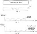
- Fig. 1is a schematic diagram of a second adapter according to an embodiment of the present disclosure.
- the second adapter 10includes a power converting circuit 11 and a control circuit 12.
- the power converting circuit 11is configured to convert an input alternating current into output voltage and output current of the second adapter 10.
- the power converting circuit 11includes a secondary filter circuit.
- the control circuit 12is coupled to the secondary filter circuit.
- the control circuit 12controls the secondary filter circuit to operate, so that the second adapter 10 outputs a constant direct current.
- the control circuit 12controls the secondary filter circuit not to operate, so that the second adapter outputs an alternating current or pulsating direct current.
- the first charging modemay be a constant voltage mode.
- the second charging modemay be a constant current mode.
- the second adapter of the embodiment of the present disclosurewhen outputting AC or pulsating direct current to charge the battery, can reduce the lithium precipitation, probability and strength of the arc of the contact of the charging interface, and improve the lifespan of the charging interface.
- the second adapter of the embodiment of the present disclosurecan switch between different charging modes flexibly.
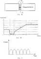
- the second the adapter operable in the second charging modecan output AC or pulsating direct current, i.e. current with pulsating waveform.
- the pulsating waveformrefers to a complete pulsating waveform, or a clipped pulsation waveform after clipping the complete pulsation waveform.
- the clippingmay refer to filtering a portion of the pulsating waveform that exceeds a threshold, to control the peak value of the pulsating waveform.
- the embodiment in Fig. 2illustrates a complete pulsating waveform.
- the embodiment in Fig. 2Billustrates the clipped pulsation waveform.
- the secondary filter circuitwhen the second adapter 10 operates in a first charging mode, the secondary filter circuit is operating normally. Current coupling from a primary side to a secondary side of the power converting circuit 11, after being rectified, must be filtered by the secondary filter circuit to output a constant direct current (i.e. a current with a steady current value).
- a constant direct currenti.e. a current with a steady current value.
- the secondary filter circuitstops operating.
- the current coupling from the primary side to the secondary side of the power converting circuit 11can be outputted directly or outputted after some simple processing.
- the output current of the second adapter 10now may be an alternating current.
- the current coupling from the primary side to the secondary side of the power converting circuit 11may be rectified, and the rectified current is outputted after some simple processing.
- the output current of the second adapter 10now is a pulsating direct current.
- the second adapter 10 of the embodiment of the present disclosurecan charge the chargeable device (terminal).
- the chargeable device (terminal) in the embodiment of the present disclosuremay be a "communication terminal" (or simply “terminal"), including but not limited to a device a device configured to be coupled via a wired connection (for example, via a public switched telephone network (PSTN), a digital subscriber line (DSL), a digital cable, a direct cable connection, and/or another data connection/network) and/or a device configured to receive/send a communication signal via a wireless interface (such as a cellular network, a wireless local area network (WLAN), a digital television network such as a DVB-H network, a satellite network, an AM-FM broadcast transmitter, and/or another communication terminal).
- PSTNpublic switched telephone network
- DSLdigital subscriber line
- a digital cablea direct cable connection
- a wireless interfacesuch as a cellular network, a wireless local area network (WLAN), a digital television network such as
- a terminal configured to communicate via a wireless interfacemay be referred to as a "wireless communication terminal", a “wireless terminal”, and/or a “mobile terminal”.
- mobile terminalinclude, but are not limited to, a satellite or cell phone; a personal communication system (PCS) terminal that can combine a cellular radiotelephone, data processing, facsimile, and data communications capabilities; may include a radiotelephone, a pager, an Internet/Intranet access, a Web browser, an electronic organizer, a calendar, and/or a personal digital assistant (PDA) equipped with a global positioning System (GPS) receiver; and a common laptop and/or palm type receiver or some other electronic devices including a transmitter-receiver of a radiotelephone.
- PCSpersonal communication system
- PDApersonal digital assistant
- GPSglobal positioning System
- the second adapter 10may include a charging interface.
- a charging interfacemay be a universal serial bus (USB) interface, which can be a standard USB interface, a micro USB port, or a Type-C interface.
- USBuniversal serial bus
- control circuit 12may also control the charging process to enhance the smartness of the second adapter.
- the control circuit 12can be applied to the chargeable device (terminal) for a bidirectional communication, to extract commands or state communication of the chargeable device (terminal) (e.g. the current voltage and temperature of the chargeable device (terminal)), which can be the basis to control the charging process of the second adapter.
- the control circuit 12may be a microcontroller unit (MCU), but the embodiment of the present disclosure does not impose a limit on this regard.
- the control circuit 12may also be other types of chips or circuits.
- the capacitor of the secondary filter circuitis a solid capacitor. It should be understood that the number of the solid capacitors may be one or more.
- the secondary filter circuitmay include a plurality of solid capacitors, which can be coupled to a secondary bus line of the second adapter or ground line. Take Fig. 3 as an example.
- the secondary filter circuitmay include four solid capacitors, coupled in parallel. It should be understood that the secondary filter circuit in Fig. 3 is just a specific example, and the number of solid capacitors of the secondary filter circuit may vary. The embodiment of the present disclosure does not impose a limit here. In the case where the total number of the capacitors in the secondary filter circuit is constant, applying a plurality of small capacitors coupled in parallel can effectively reduce the equivalent resistance and the equivalent inductance of the capacitor, so that the direct current outputted by the secondary filter circuit is more stable.
- the capacitance or number of the capacitorscan be confirmed depending on a maximum current allowed to be outputted by the second adapter operable in the first charging mode.
- a need to boost the maximum current allowed to be outputted by the second adaptercan be met by increasing the capacitance and/ or number of capacitors in the secondary filter circuit.
- the VBUS terminal of the second adaptermay also be coupled to a number of ceramic capacitors to filter some ripples in the output voltage and output current of the second adapter.
- the control circuit 12can be coupled to the second filter circuit through a metal oxide semiconductor (MOS) transistor.
- MOSmetal oxide semiconductor
- a gate of the MOS transistoris coupled to the control circuit 12
- a source of the MOS transistoris grounded
- a drain of the MOS transistoris coupled to an end of the capacitor in the secondary filter circuit.
- the control circuit 12may control the on and off of the MOS transistor via a pulse-width- modulation (PWM) signal.
- PWMpulse-width- modulation
- control circuit 12an control the on and off of the MOS transistor via other types of signals other than the PWM signal.
- the abovementioned MOS transistorcan be a N-channel enhancement type MOS transistor, or other types of MOS transistors.
- control circuit 12may also adopt other components that functions as a switch to control the operation of the secondary filter circuit. The embodiment of the present disclosure does not impose a limit on this regard.
- the second adapter 10may support the first charging mode and the second charging mode.
- the adapter operable in the second charging modecharges the chargeable device (terminal) faster than the adapter operable in the first charging mode charges the chargeable device (terminal). In other words, it takes less time for the adapter to charge the battery with the same electricity volume under the second charging mode compared with the adapter under the first charging mode.
- the second adapter 10includes a control circuit.
- the control circuitundertakes the bidirectional communication with the chargeable device (terminal), to control the charging process of the second charging mode.
- the control circuitmay be a control circuit in any of the abovementioned embodiments, such as a control circuit in a first adjustment circuit or a control circuit in a second adjustment circuit.
- the first charging modemay be a normal charging mode.
- the second charging modemay be a fast charging mode.
- the normal charging modemeans that the second adapter outputs a comparably smaller amount of current (usually less than 2.5A) or a comparably smaller amount of power (usually less than 15W) to charge a battery in the chargeable device (terminal). It usually takes several hours to fill up a battery with a larger amount (like with an amount of 3000 milliampere) on the normal charging mode.
- the adapteroutputs a comparably larger amount of current (usually greater than 2.5A, like 4.5A, 5A, or more) or a comparably larger amount of power (usually more than or equal to 15W) to charge the battery in the chargeable device (terminal) by the fast charging mode.
- the charging rate of the second adapteris faster on the fast charging mode so it takes less time to full up a battery with the same volume obviously.
- the embodiment of the present disclosuredoes not impose specific limits on the communicated content between the control circuit of the second adapter and the chargeable device (terminal), and the control method adopted by the control circuit when controlling the second adapter operable in the second charging mode.
- the control circuitcan communicate with the chargeable device (terminal), extract information about the present voltage or current of the battery in the chargeable device (terminal), and adopt the output voltage or current of the second adapter accordingly.
- the following textdescribes in detail the control method of the control circuit when controlling the second adapter operable in the second charging mode.
- control circuitundertakes a bidirectional communication with the chargeable device (terminal), to control the output process of the second adapter operable in the second charging mode.
- the processmay include the bidirectional communication between the control circuit and the chargeable device (terminal) to negotiate a charging mode which the chargeable device and the second adapter are operable in (terminal).
- the second adapterdoes not always adopt the second charging mode to charge the chargeable device (terminal), but engage in the bidirectional communication with the chargeable device (terminal) to negotiate whether the second adapter may employ the second charging mode on the chargeable device (terminal) for fast charging. It can enhance the safety of the charging process.
- the control circuitundertakes the bidirectional communication with the chargeable device (terminal), to negotiate the charging mode between the second adapter and the chargeable device (terminal).
- the processcan include the control circuit sending to the chargeable device (terminal) a first instruction, which is configured to inquire the chargeable device (terminal) whether to enable the second charging mode.
- the control circuitreceives a reply instruction responsive to the first instruction sent by the chargeable device (terminal).
- the reply instructionis configured to show whether the chargeable device (terminal) approves to enable the second charging mode. If the chargeable device (terminal) approved to enable the second charging mode, the control circuit will charge the chargeable device (terminal) in the second charging mode.
- the control circuit or the chargeable device (terminal)can be the master side and initiate the bidirectional communication.
- the other sidecan serve as the slave side to generate a first response or first reply.
- the decision of which device should be the master or slavecan be made by comparing the levels of the second adapter and the chargeable device (terminal) relative to the earth during the communication process.
- the embodiment of the present disclosuredoes not impose limits on the specific implementation of the bidirectional communication between the second adapter (or the control circuit of the second adapter) and the chargeable device (terminal).
- either the second adapter (or the control circuit of the second adapter) or the chargeable device (terminal)can be the master device to initiate the communication.
- the other sidecan serve as the slave device to generate a first response or first reply in the communication initiated by the master device.
- the master devicecan generate a second response towards the first response or first reply of the slave device, it is considered that a negotiation process on charging mode has been completed between the master and slave devices.
- the charging operationcan take place after the master and slave devices have completed several rounds of negotiation on the charging mode to ensure that the charging process after the negotiation is safe and reliably executed.
- the master devicecan receive the first response or first reply generated by the slave device specifically for the communication, and make a second response specifically towards the first response or first reply generated by the slave device. For example, when the master device receives a first response or first reply generated by the slave device specifically for the communication within a designated period of time, the master device generates the specific second response towards the first response or first reply generated by the slave device. More specifically, when the master device and the slave device completes a round of negotiation on the charging mode, the master device and the slave device perform the first charging mode or the second charging mode in accordance with the negotiation result. That is, the second adapter charges the chargeable device (terminal) in the first charging mode or the second charging mode according to the negotiation result.
- Another method that the master device may adopt to generate the second response towards the first response or first reply generated by the slave device specifically for the communicationmay be: the master device does not receive the first response or first reply generated by the slave device specifically for the communication within the designated period of time, but the master device still generates the specific second response towards the first response or first reply generated by the slave device specifically for the communication. For example, when the master device does not receive the first response or first reply generated by the slave device specifically for the communication within the designated period of time, the master device still generates the specific second response towards the first response or first reply generated by the slave device. More specifically, the master device and slave device complete a round of negotiation on the charging mode, and the master device and slave device will perform the charging operation in the first charging mode, meaning that the second adapter charges the chargeable device (terminal) in the first charging mode.
- the second adapterwhen the chargeable device (terminal) serve as the master device to initiate the communication, the second adapter (or the control circuit of the second adapter) generates a first response or first reply specifically for the communication initiated by the master device. Then, a round of negotiation on the charging mode is considered completed between the second adapter (or the control circuit of the second adapter) and the chargeable device (terminal), and there is no need to wait for a specific second response generated by the chargeable device (terminal) towards the first response or first reply of the second adapter. Therefore, the second adapter can decide to charge the chargeable device (terminal) in the first charging mode or the second charging mode according to the negotiation result.
- control circuit and the chargeable device (terminal)engage in the bidirectional communication, to control the output of the second adapter operable in the second charging mode.
- the processmay include: the control circuit and the chargeable device (terminal) engage in the bidirectional communication to determine the charging voltage for the chargeable device (terminal) outputted by the second adapter operable in the second charging mode; the control circuit adjusts the output voltage of the second adapter so that it (or the peak value of the output voltage of the second adapter) is equal to the charging voltage for the chargeable device (terminal) outputted by the second adapter operable in the second charging mode.
- control circuit and the chargeable device (terminal)engage in the bidirectional communication, to determine the charging voltage for the chargeable device (terminal) outputted by the second adapter operable in the second charging mode.
- the processmay include: the control circuit sends to the chargeable device (terminal) a second instruction which is configured to inquire whether the output voltage of the second adapter matches the present voltage of the battery in the chargeable device (terminal).
- the control circuitreceives a reply instruction responsive to the second instruction sent by the chargeable device (terminal), which is configured to show whether the output voltage of the second adapter matches, or is higher or lower than, the present voltage of the battery.
- the second instructioncan be configured to inquire whether it is appropriate to utilize the present output voltage of the second adapter as the charging voltage to be outputted by the second adapter for the chargeable device (terminal) in the second charging mode.
- the reply instruction responsive to the second instructioncan be configured to show whether the present output voltage of the second adapter is appropriate, or higher or lower.
- the present voltage of the second adaptermatches the present voltage of the battery, or when it is appropriate to be used as the charging voltage to be outputted by the second adapter for the chargeable device (terminal) in the second charging mode, it may mean that the present output voltage of the second adapter (or the peak value of the present output voltage) is slightly higher than the present voltage of the battery, and the gap between the output voltage of the second adapter (or the peak value of the present output voltage) and the present voltage of the battery is within a predetermined range (typically within a few hundred millivolts).
- control circuit and the chargeable device (terminal)engage in the bidirectional communication to control the charging process outputted by the second adapter in a second charging mode.
- the processmay include: the control circuit and the chargeable device (terminal) engage in a bidirectional communication to determine a charging current outputted by the second adapter for the chargeable device (terminal) in the second charging mode.
- the control circuitadjusts the output current of the second adapter (or the peak value of the output current of the second adapter), so that the output current of the second adapter (or the peak value of the output current of the second adapter) is equal to the charging current outputted by the second adapter for the chargeable device (terminal) in the second charging mode.
- control circuit and the chargeable device (terminal)engage in the bidirectional communication to determine the charging current outputted by the second adapter for the chargeable device (terminal) in the second charging mode.
- the processmay include: the control circuit sends to the chargeable device (terminal) a third instruction, which is configured to inquire the present maximum charging current supported by the chargeable device (terminal).
- the control circuitreceives a reply instruction responsive to the third instruction, which is configured to show the present maximum charging current supported by the chargeable device (terminal).
- the control circuitdetermines the charging current outputted by the second adapter for the chargeable device (terminal) by the second charging mode based on the present maximum charging current supported by the chargeable device (terminal).
- control circuitcan apply many methods to determine the charging current outputted by the second adapter for the chargeable device (terminal) by the second charging mode based on the present maximum charging current supported by the chargeable device (terminal).
- the second adaptercan determine the present maximum charging current supported by the chargeable device (terminal) as the charging current (or the peak value of the charging current) outputted by the second adapter for the chargeable device (terminal) in the second charging mode.
- Another methodis to determine the charging current outputted by the second adapter for the chargeable device (terminal) by the second charging mode after taking into consideration the present maximum charging current supported by the chargeable device (terminal), the capacity to output current and other factors.
- control circuit and the chargeable device (terminal)engage in bidirectional communication to control the output of the second adapter operable in the second charging mode.
- the processmay include: the control circuit and the chargeable device (terminal) engage in a bidirectional communication while the second adapter is charging the chargeable device (terminal) in the second charging mode, to adjust the output current of the second adapter.
- control circuit and the chargeable device (terminal) engage in bidirectional communication to adjust the output current of the second adaptermay include: the control circuit sends to the chargeable device (terminal) a fourth instruction, which is configured to inquire the present voltage of battery in the chargeable device (terminal).
- the control circuitreceives a reply instruction responsive to the fourth instruction sent by the second adapter, which is configured to show the present voltage of the battery.
- the control circuitadjusts the output current of the second adapter according to the present voltage of the battery.
- the second adapter 10includes a charging interface 51. Furthermore, in some embodiments, the control circuit of the second adapter 10 can engage in the bidirectional communication with the chargeable device (terminal) through a data line 52 of the charging interface 51.
- control circuit and the chargeable device (terminal)engage in the bidirectional communication to control the output of the second adapter operable in the second charging mode.
- the processmay include: the control circuit and the chargeable device (terminal) engage in the bidirectional communication to confirm whether the charging interface is poorly coupled.
- control circuit and the chargeable device (terminal)engage in the bidirectional communication to confirm whether the charging interface is poorly coupled.
- the processmay include: the control circuit sends to the chargeable device (terminal) the fourth instruction, which is configured to inquire the present voltage of the battery of the chargeable device (terminal).
- the control circuitreceives a reply instruction responsive to the fourth instruction sent by the chargeable device (terminal), which is configured to show the present voltage of the battery in the chargeable device (terminal).
- the control circuitconfirms whether the charging interface is poorly coupled according to the output voltage of the second adapter and the present voltage of the battery in the chargeable device (terminal).
- control circuitconfirms that the gap between the output voltage of the second adapter and the present voltage of the battery of the chargeable device (terminal) is larger than a predetermined voltage threshold, it means that the impedance resulted from diving the voltage gap by the present current outputted by the second adapter is larger than the predetermined impedance threshold, thus it is confirmed that the charging interface is poorly coupled.
- whether the charging interface is poorly coupledcan be confirmed by the chargeable device (terminal).
- the processmay include: the chargeable device (terminal) sends to the control circuit a sixth instruction, which is configured to inquire the output voltage of the second adapter.
- the chargeable device (terminal)receives a reply instruction responsive to the sixth instruction sent by the control circuit, which is configured to show the output voltage of the second adapter.
- the chargeable device (terminal)confirms whether the charging interface is poorly coupled based on the present voltage of the battery of the chargeable device (terminal) and the output voltage of the second adapter.
- the chargeable device (terminal)After the chargeable device (terminal) confirms that the charging interface is poorly coupled, the chargeable device (terminal) sends a fifth instruction to the control circuit, which is configured to show that the charging interface is poorly coupled.
- the control circuitcan control the second adapter to exit the second charging mode after receiving the fifth instruction.
- Fig. 5Bthe present embodiment details a communication process between the control circuit of the second adapter and the chargeable device (terminal). It is understood that the example illustrated in Fig. 5B merely help a person skilled in the art understand the present embodiment rather than limit the number of scenes. A person skilled in the art can modify or change the embodiment correspondingly according to the example illustrated in Fig. 5B . Such modifications or changes are within the scope of the present embodiment.
- the communication process between the second adapter and the chargeable devicemay include Stage 1, Stage 2, Stage 3, Stage 4, and Stage 5.
- the chargeable device (terminal)may detect the type of power supply device via data lines D+ and D-.
- the chargeable device (terminal)detects the power supply device to be the second adapter, the current absorbed by the chargeable device (terminal) is greater than the predetermined current threshold I2 (such as 1A).
- the predetermined current threshold I2such as 1A
- the second adapterdetects the current outputted by the second adapter greater than or equal to the predetermined current threshold I2 within the predetermined duration (for example, a continuous T1 duration)
- the second adaptermay regard the type of the power supply device is recognized by the chargeable device (terminal).
- the second adapterstarts to negotiate with the chargeable device (terminal) and sends instruction 1 (corresponding to the above-mentioned first instruction) to the chargeable device (terminal) to inquire whether the chargeable device (terminal) agrees the second adapter to charge the chargeable device (terminal) by the second charging mode.
- the second adapterWhen the second adapter receives the reply instruction responsive to instruction 1 sent by the chargeable device (terminal), and the reply instruction responsive to Instruction 1 instructions the chargeable device (terminal) to not agree the second adapter to charge the chargeable device (terminal) by the second charging mode, the second adapter detects the output current of the second adapter again. When the current outputted by the second adapter is still greater than or equal to I2 in a predetermined continuous duration (for example, a continuous T1 duration), the second adapter sends the reply instruction responsive to instruction 1 to the chargeable device (terminal) again. The second adapter inquires the chargeable device (terminal) to agree to charge the chargeable device (terminal) with the second adapter on the second mode.
- a predetermined continuous durationfor example, a continuous T1 duration
- the second adapterrepeats the operation at Stage 1 until the chargeable device (terminal) agrees the second adapter to charge the chargeable device (terminal) on the second mode or the current outputted by the second adapter no longer satisfies the requirement of the output current greater than or equal to I2.
- the communication processenters Stage 2.
- the voltage outputted by the second adaptermay include a plurality of levels.
- the second adaptersends instruction 2 to the chargeable device (terminal) (corresponding to the second instruction) to inquire whether the voltage outputted by the second adapter (the present output voltage) matches the present total voltage of the chargeable device (terminal).
- the chargeable device (terminal)sends the reply instruction responsive to Instruction 2 to command the voltage outputted by the second adapter to match the present total voltage of the chargeable device (terminal) or to make the voltage outputted by the second adapter and the present total voltage of the chargeable device (terminal) higher or lower. If the reply instruction responsive to Instruction 2 is to make the voltage outputted by the second adapter and the present total voltage of the chargeable device (terminal) higher or lower, the second adapter can adjust one level of the voltage outputted by the second adapter and sends the reply instruction responsive to Instruction 2 to the chargeable device (terminal) to inquire whether the voltage outputted by the second adapter matches the present voltage of the battery again. The operation at Stage 2 are repeated until the chargeable device (terminal) ensures that the voltage outputted by the second adapter matches the present voltage of the battery. Afterwards, Stage 3 starts.
- the second adaptersends Instruction 3 (corresponding to the above-mentioned the third instruction) and inquires the maximum charging current supported by the chargeable device (terminal) currently.
- the chargeable device (terminal)sends the reply instruction responsive to Instruction 3 to the second adapter to command the maximum charging current supported by the chargeable device (terminal) currently.
- Stage 4starts.
- Stage 5Based on the maximum charging current supported by the chargeable device (terminal) currently, the charging current outputted by the second adapter to charge the chargeable device (terminal) under the second charging mode. Afterwards, Stage 5 starts, that is, constant current charging stage.
- the second adapterWhen entering the constant current charging stage, the second adapter sends Instruction 4 (corresponding to the above-mentioned fourth instruction) to the chargeable device (terminal) every interval of time and inquire the present voltage of the battery of the chargeable device (terminal). The chargeable device (terminal) sends the reply instruction responsive to Instruction 4 to the second adapter to feedback the present voltage of the battery.
- the second adaptercan detect whether the connection of the charging interface is normal based on the present voltage of the battery and whether the current outputted by the second adapter needs lower.
- the chargeable device (terminal)sends Instruction 5 (corresponding to the above-mentioned fifth instruction), the second adapter retreats from the second charging mode, resets to enter Stage 1.
- the chargeable device (terminal)sends a reply instruction responsive to Instruction 1 at Stage 1.
- the reply instruction responsive to Instruction 1may attach data (or information) of a path impedance of the chargeable device (terminal).
- the connection of the charging interfaceis detected to be normal with the path impedance of the chargeable device (terminal) at Stage 5.
- a time periodfrom the time that the chargeable device (terminal) agrees the second adapter charging the chargeable device (terminal) by the second charging mode until the time that an output voltage of the second adapter is adjusted to a suitable charging voltage, may be set as a predetermined time period at Stage 2. If the time goes beyond the predetermined time period, the second adapter or the chargeable device (terminal) is detected to be abnormal in the communication process and then resets to enter Stage 1.
- the voltage outputted by the second adapteris higher than the present voltage of the battery of the chargeable device (terminal) by ⁇ V ( ⁇ V can range from 200 mV to 500 mV) at Stage 2.
- the chargeable device (terminal)may send a reply instruction responsive to Instruction 2 to the second adapter to command the voltage outputted by the second adapter to match the voltage of the battery of the chargeable device (terminal).
- the adjustment speed of a current outputted by the second adaptercan be controlled within limits at Stage 4. In this way, the charging process will not be abnormal once the adjustment speed is too high.
- a variation of a current outputted by the second adapteris controlled within five percent (5%) of the output current at Stage 5.
- the control circuitcan detect a path impedance of a charging circuit in real time at Stage 5. Specifically, the control circuit can detect the path impedance of the charging circuit based on an output voltage and an output current of the second adapter and the present voltage (present total voltage of the multiple cells) of the battery feedback by the chargeable device (terminal). Since "path impedance of charging circuit" greater than "path impedance of charging circuit plus impedance of charging cable" indicates a bad contact of a charging interface, the second adapter stops charging the chargeable device (terminal) under the second charging mode.
- communication interval between the control circuit and the chargeable device (terminal)is controlled within limits to prevent abnormality from occurring in the communication process because the interval is too short.
- termination of the charging processmay be divided into recoverable termination and unrecoverable termination.
- the charging processterminates, the charging communication process resets, and the charging process enter Stage 1 again. Afterwards, the charging process enters Stage 2 if the chargeable device (terminal) does not agree the second adapter to charge the chargeable device (terminal) by the second charging mode.
- Such kind of termination of the charging processis regarded as unrecoverable termination.
- the charging processterminates, the charging communication process resets, and the charging process enters Stage 1 again.
- the chargeable device (terminal)agrees the second adapter to charge the chargeable device (terminal) under the second charging mode to recover the charging process.
- Such kind of termination of the charging processmay be regarded as recoverable termination.
- the chargeable device (terminal)detects the battery is abnormal, the charging process terminates, the charging process resets, and the charging process enters Stage 1 again. Afterwards, the chargeable device (terminal) does not agree the adapter to charge the chargeable device (terminal) under the second charging mode. When the battery (the multiple cells) becomes normal again, and the requirement of Stage 1 is fulfilled, the chargeable device (terminal) agrees the adapter to charge the chargeable device (terminal) under the second charging mode.
- Such kind of termination of the charging processmay be regarded as recoverable termination.
- Fig. 5BThe blocks or operations illustrated in Fig. 5B are merely an exemplary.
- handshake communication between the chargeable device (terminal) and the second adaptermay be launched by the chargeable device (terminal) as well; that is the chargeable device (terminal) sends Instruction 1 and inquires whether the second adapter enables the second charging mode.
- the chargeable device (terminal)receives the reply instruction responsive to the second adapter to command the second adapter to agree to charge the chargeable device (terminal) by the second charging mode
- the second adapterstarts to charge the battery of the chargeable device (terminal) by the second charging mode.
- a stage of constant voltage chargingmay be further included after Stage 5 finishes.
- the chargeable device (terminal)feedbacks the present voltage of the battery (the present total voltage of the multiple cells) to the second adapter at Stage 5.
- the present voltage of the batterythe present total voltage of the multiple cells
- the chargeable device (terminal)is charged by a constant voltage from the constant current.
- the charging currentgradually lessens.
- the battery of the chargeable device (terminal)is filled.
- the second adapterdirectly couples its output current to the positive terminal and negative terminal of the battery of the chargeable device (terminal), directly charging the battery.
- direct chargingmay refer to directly coupling (or directly leading) the output voltage and output current of the second adapter to the positive terminal and negative terminal of the battery of the chargeable device (terminal). It does not need to go through a converter circuit to convert the output voltage or output current of the second adapter to avoid energy loss caused by the conversion process.
- the second adapterin order to be able to adjust the charging voltage or charging current on the charging circuit, can be designed as an intelligent adapter, so that the second adapter can complete the conversion of the charging voltage or charging current. It can reduce the load of and the heat emitted by the chargeable device (terminal).
- the second adapter 10 of the embodiment of the present disclosurecan operate in a constant current mode.
- the constant current modeherein refers to a charging mode in which control is exercised on the output current of the second adapter, instead of keeping the output current of the second adapter to stay constant.
- the second adapter in a constant current modetypically adopts a multi-stage constant current charging.
- the multi-stage constant current charginghas N charging stages (N is an integer equal to or larger than 2).
- the multi-stage constant current chargingcan begin the first stage charging by a predetermined charging current.
- the N charging stages of the multi-stage constant current chargingare executed sequentially from the first stage to the (N-1) stage.
- the charging currentgradually decreases.
- the battery voltagereaches the charge cut-off voltage, the previous charging stage will transit to the next charging stage in the charging process.
- the output current of the second adapteris a pulsating direct current (also known as unidirectional pulsating output current, or pulsating waveform current, or clipped pulsating waveform current).
- a pulsating direct currentalso known as unidirectional pulsating output current, or pulsating waveform current, or clipped pulsating waveform current.
- the waveform of the pulsating direct currentis illustrated in Fig. 6 .
- constant current modemay refer to a charging mode that exercises control over the peak value or average value of the pulsating direct current, i.e. controlling the peak value of the output current of the second adapter not exceeding the corresponding current of the constant current mode, as illustrated in Fig. 7 .
- the output current of the second adapteris an alternating current, which can also reduce lithium precipitation of lithium batteries and improve the lifespan of the cell.
- Fig. 8illustrates a flowchart of a method of controlling a charging process according to an embodiment of the present disclosure.
- the method illustrated in Fig. 8is performed by the second adapter as illustrated in Figs. 1-7 .
- the second adapterincludes a power converting circuit configured to convert inputted alternating current (AC) to generate output voltage and output current.
- the power converting circuitincludes a secondary filter circuit.
- the method illustrated in Fig. 8includes a block 810 and a block 820.
- the secondary filter circuitis controlled to operate when the second adapter operates in a first charging mode, so that the second adapter outputs constant direct current.
- the secondary filter circuitdoes not operate when the second adapter operates in a second charging mode, so that the second adapter outputs an alternating current or a pulsating direct current.
- a capacitor of the secondary filter circuitis a solid capacitor.
- the secondary filter circuitincludes a plurality of solid capacitors coupled to a secondary bus line of the adapter and ground.
- a speed by which the second adapter charges the chargeable device by the second charging modeis faster than a speed by which the second adapter charges the chargeable device in the first charging mode.
- the method illustrated in Fig. 8further includes: engaging in a bidirectional communication with the chargeable device to control the output of the second adapter operable in the second charging mode when the second adapter coupled to the chargeable device is operable in the second charging mode.
- the engaging in the bidirectional communication with the chargeable device to control the output of the second adapter operable in the second charging mode when the second adapter coupled to the chargeable device is operable in the second charging modeincludes: engaging in the bidirectional communication with the chargeable device to negotiate a charging mode which the chargeable device and the second adapter are operable in.
- the engaging in the bidirectional communication with the chargeable device to negotiate a charging mode which the chargeable device and the second adapter are operable inincludes: sending a first instruction to the chargeable device, the first instruction configured to inquire whether the chargeable device enables the second charging mode, receiving a reply instruction responsive to the first instruction sent by the chargeable device, which is configured to indicate whether the chargeable device approves to enable the second charging mode, and charging the chargeable device by the second charging mode when the chargeable device approves to enable the second charging mode.
- the engaging in the bidirectional communication with the chargeable device to control the output of the second adapter operable in the second charging mode when the second adapter coupled to the chargeable device is operable in the second charging modeincludes: engaging in the bidirectional communication with the chargeable device to determine the charging voltage outputted by the second adapter to charge the chargeable device by the second charging mode, and adjusting the output voltage of the second adapter so that the output voltage of the second adapter is equal to the charging voltage outputted by the second adapter to charge the chargeable device by the second charging mode.
- the engaging in the bidirectional communication with the chargeable device to determine the charging voltage outputted by the second adapter to charge the chargeable device by the second charging modeincludes: sending to the chargeable device a second instruction, which is configured to inquire whether the output voltage of the second adapter is equal to the present voltage of the battery in the chargeable device, receiving a reply instruction responsive to the second instruction sent by the chargeable device, which is configured to indicate whether the output voltage of the second adapter matches, or is higher or lower than the present voltage of the battery.
- the engaging in the bidirectional communication with the chargeable device to control the output of the second adapter operable in the second charging mode when the second adapter coupled to the chargeable device is operable in the second charging modeincludes: engaging in the bidirectional communication with the chargeable device to determine the charging current outputted by the second adapter to charge the chargeable device in the second charging mode, and adjusting the output current of the second adapter, so that the output current of the second adapter is equal to the charging current outputted by the second adapter to charge the chargeable device in the second charging mode.
- the engaging in the bidirectional communication with the chargeable device to determine the charging current outputted by the second adapter to charge the chargeable device in the second charging modeincludes: sending to the chargeable device a third instruction, which is configured to inquire the maximum charging current presently supported by the chargeable device, receiving a reply instruction responsive to the third instruction sent by the chargeable device, which is configured to show the maximum charging current presently supported by the chargeable device, and determining the charging current outputted by the second adapter to charge the chargeable device by the second charging mode based on a maximum charging current presently supported by the chargeable device.
- the engaging in the bidirectional communication with the chargeable device to control the output of the second adapter operable in the second charging mode when the second adapter coupled to the chargeable device is operable in the second charging modeincludes: engaging in the bidirectional communication with the chargeable device to adjust the output current of the second adapter.
- the engaging in the bidirectional communication with the chargeable device to adjust the output current of the second adapterincludes: sending to the chargeable device a fourth instruction, which is configured to inquire the present voltage of the battery of the chargeable device, and receiving a reply instruction responsive to the fourth instruction sent by the chargeable device, which is configured to indicate the present voltage of the battery, and adjusting the output current of the second adapter based on the present voltage of the battery.
- the second adaptercomprises a charging interface, and the second adapter performs bidirectional communication with the chargeable device through a data line of the charging interface.
- the output current of the second adapter operable in the second charging modeis a pulsating direct current.
- the output current of the second adapter operable in the second charging modeis an alternating current.
- the output voltage and output current of the second adapterare directly applied a positive terminal and a negative terminal of a battery in the chargeable device to directly charge the battery in the second charging mode.
- the second adaptercomprises a control circuit configured to control the charging process; the control circuit is a microcontroller unit (MCU).
- MCUmicrocontroller unit
- the second adaptercomprises a charging interface, which is an universal serial bus (USB) interface.
- USBuniversal serial bus
- first adapterand “second adapter” are used for illustrative purposes only but are not limited to a specific type adapter.
- the revealed system, device and methodmay be implemented in other ways.
- the abovementioned embodiments of the deviceare merely schematic.
- the division of the unitsis merely a division based on logical functions; it may be different when they are put into practice.
- a plurality of units or componentsmay be combined or integrated into another system, or some features may be ignored or not be performed.
- the displayed or discussed coupling, direct coupling or communicationcan be done through some interfaces, devices, or indirect coupling or communication between units; they may be electrical, mechanical, or in other forms.
- the units described as separated partsmay or may not be physically separated.
- a part that appeared as a unitmay or may not be a physical unit, i.e. it can locate in one place, or it can be distributed to multiple network units. Part of or all of the units can be selected based on actual needs to achieve the object of the solutions of the present embodiments.
- each of the functional units in the embodiments of the present disclosuremay be integrated in one processing unit, or may be independent units physically separated, or may integrate with another one or more units and appear as a single unit.
- the functionis realized as a software functional unit and used or sold as a standalone product, it may be stored in a computer-readable storage medium. Based on such understanding, the technical solutions of the present disclosure per se, or its contribution to the related art, or the technical solution may be realized in a software product.
- the computer software productis stored in a storage medium, including several commands that enable a computer device (may be a personal computer, a server, or network device) to perform all or part of the steps of the methods of the various embodiments of the present disclosure.
- the storage mediumincludes U-disk, removable hard disk, read-only memory (ROM), random access memory (RAM), magnetic disk or compact disc (CD) and other medium that can store program codes.
Landscapes
- Engineering & Computer Science (AREA)
- Power Engineering (AREA)
- Chemical & Material Sciences (AREA)
- Manufacturing & Machinery (AREA)
- Chemical Kinetics & Catalysis (AREA)
- Electrochemistry (AREA)
- General Chemical & Material Sciences (AREA)
- Physics & Mathematics (AREA)
- Microelectronics & Electronic Packaging (AREA)
- General Physics & Mathematics (AREA)
- Materials Engineering (AREA)
- Electromagnetism (AREA)
- Charge And Discharge Circuits For Batteries Or The Like (AREA)
- Secondary Cells (AREA)
- Dc-Dc Converters (AREA)
- Direct Current Feeding And Distribution (AREA)
- Theoretical Computer Science (AREA)
- Emergency Protection Circuit Devices (AREA)
- Protection Of Static Devices (AREA)
- Rectifiers (AREA)
Description
- The present disclosure relates to the field of charging, and more particularly, to an adapter and a method of controlling a charging process.
- Adapters are also known as power adapters, which are used for charging chargeable devices (such as terminals). Currently, existing adapters typically charges chargeable devices in a constant voltage mode. Since batteries of devices to be charged are mostly lithium batteries, charging the batteries with the constant voltage is likely to cause lithium precipitation, resulting in reduced battery life.
- Prior art document
US 2008/197811 A1 relates to circuits and methods for charging a battery pack. A battery charging circuit comprises an AC to DC converter, a charging control switch, and a charger controller, wherein the AC to DC converter provides a charging power to a battery pack. The charging control switch is coupled between the AC to DC converter and the battery pack and transfers the charging power to the battery pack. The charger controller detects a battery status of the battery pack and controls the charging control switch to charge the battery pack in a continuous charging mode or a pulse charging mode according to the battery status. The charger controller also controls the AC to DC converter to regulate the charging power according to the battery status. - Prior art document
US 2013/300375 A1 relates to systems and methods for high power factor charging. A charging system includes a rectifier and a power converter, wherein the power converter performs a DC-to-DC conversion to provide a lower DC voltage at the charging system output than a DC rectifier output voltage. A controller is configured to output control signals to a control switch, as well as to the power converter, so that the output voltage remains within a particular range. - Prior art document
EP 2 887 492 A2 relates to a method and apparatus for charging a battery. The provided method comprises detecting a connection between an electronic device and a battery charger 110, transmitting a first request for at least one of a first voltage level and a first current level to the battery charger, receiving a signal from the battery charger, and charging a battery of the electronic device with the signal. - Prior art document
US 2014/159641 A1 relates to battery chargers using a single conversion power supply to charge multiple battery types having different maximum voltage cutoff levels. A single conversion switched mode power supply has a bias winding on the primary side of the power transformer, wherein the bias winding produces an output that is proportional to the voltage produced on the secondary winding, and is sensed by a programmable voltage sensing circuit. The programmable voltage sensing circuit is programmed by a voltage select signal from the secondary side of the charger to produce a sense signal that is proportional to the output of the bias winding by a selected factor corresponding to a battery type of a battery being charged. - The present disclosure provides an adapter and a method of controlling a charging process, in order to reduce the lithium precipitation of lithium batteries, and improve battery life. The invention is set out in the appended claims.
- According to a first aspect of the present disclosure, an adapter supporting a first charging mode and a second charging mode is provided. The adapter includes a power converting circuit and a control circuit. The power converting circuit is configured to convert inputted alternating current (AC) to generate output voltage and output current of the adapter, the power converting circuit comprising a secondary filter circuit. The control circuit is coupled to the secondary filter circuit and configured to control the secondary filter circuit to operate when the adapter operates in the first charging mode, so that the adapter outputs constant direct current, and configured to control the secondary filter circuit not to operate when the adapter operates in the second charging mode, so that the adapter outputs an alternating current or a pulsating direct current.
- According to a second aspect of the present disclosure, a method of controlling a charging process performed by an adapter is provided. The adapter includes a power converting circuit configured to convert inputted alternating current (AC) to generate output voltage and output current. The power converting circuit includes a secondary filter circuit. The method includes the following operation. The secondary filter circuit is controlled to operate when the adapter operates in a first charging mode, so that the adapter outputs constant direct current. The secondary filter circuit does not operate when the adapter operates in a second charging mode, so that the adapter outputs an alternating current or a pulsating direct current.
- The adapter of the embodiment of the present disclosure, when outputting alternating current (AC) or pulsating direct current, can reduce the lithium precipitation, the probability and strength of the arc of the contact of the charging interface, and improve the lifespan of the charging interface. In addition, the adapter of the present disclosure can switch flexibly between different charging modes.
- To describe the technical solutions in the embodiments of this application more clearly, the following briefly introduces the accompanying drawings required for describing the embodiments. Apparently, the accompanying drawings in the following description show merely some embodiments of this application, and a person of ordinary skill in the art may still derive other drawings from these accompanying drawings without creative efforts.
FIG. 1 illustrates a schematic diagram of a second adapter according to one embodiment of the present disclosure.FIGs. 2A and 2B illustrate pulsating waveforms according to one embodiment of the present disclosure.FIG. 3 illustrates a block schematic diagram of a second adapter according to another embodiment of the present disclosure.FIG. 4 illustrates a block schematic diagram of a second adapter according to still another embodiment of the present disclosure.FIG. 5A illustrates a connection between a chargeable device and a second adapter according to one embodiment of the present disclosure.FIG. 5B illustrates a timing diagram of a fast charging process according to one embodiment of the present disclosure.FIG. 6 illustrates a waveform of a pulsating direct current.FIG. 7 illustrates a waveform of a pulsating direct current under the constant current mode according to one embodiment of the present disclosure.FIG. 8 illustrates a flowchart of a method of controlling a charging process according to one embodiment of the present disclosure.- To help a person skilled in the art better understand the solutions of the present disclosure, the following clearly and completely describes the technical solutions in the embodiments of the present invention with reference to the accompanying drawings in the embodiments of the present invention. Apparently, the described embodiments are a part rather than all of the embodiments of the present invention. All other embodiments obtained by a person of ordinary skill in the art based on the embodiments of the present invention without creative efforts shall fall within the protection scope of the present disclosure.
- The present disclosure proposes a first adapter for charging a chargeable device (e.g. a terminal) in the relevant technology. The first adapter constantly maintains an output voltage when the first adapter operates in a constant voltage mode, such as 5V, 9V, 12V, or 20V, etc.
- Voltage output from the first adapter is not suitable to be directly applied to a positive terminal and a negative terminal of a battery. Rather, the voltage output from the first adapter needs to be first converted through a converter circuit in a chargeable device (terminal) so as to obtain an expected charging voltage and/or a charging current by a battery in the chargeable device (terminal).
- The converter circuit is configured to convert the voltage output from the first adapter so as to satisfy the expected requirement of the charging voltage and/or the charging current by the battery.
- As an example, the converter circuit may refer to a charging management module, such as a charging integrated circuit (IC), which is configured to manage the charging voltage and/or the charging circuit of the battery during the charging process of the battery. The converter circuit has a function of a voltage feedback module and/or a function of a current feedback module to manage the charging voltage and/or the charging circuit of the battery.
- For example, the charging process of the battery may include at least one of a trickle charging stage, a constant current charging stage, and a constant voltage charging stage. During the trickle charging stage, the converter circuit can utilize a current feedback loop so that a current entering into the battery satisfies a magnitude of the charging current expected by the battery (such as a first charging current) in the trickle charging stage. During the constant current charging stage, the converter circuit can utilize the current feedback loop so that the current entering into the battery satisfies magnitude of the charging current expected by the battery (such as a second charging current, the second charging current may be greater than the first charging current) in the constant current charging stage. During the constant voltage charging stage, the converter circuit can utilize a voltage feedback loop so that a voltage applied between a positive terminal and a negative terminal of the battery satisfies a magnitude of the charging voltage expected by the battery in the constant voltage charging stage.
- As an example, when the voltage output from the first adapter is greater than the charging voltage expected by the battery, the converter circuit can be configured to step down the voltage output from the first adapter so that the charging voltage obtained after buck conversion satisfies the charging voltage expected by the battery. As another example, when the voltage output from the first adapter is less than the charging voltage expected by the battery, the converter circuit can be configured to boost the voltage output from the first adapter so that the charging voltage obtained after the boost conversion satisfies the charging voltage expected by the battery.
- In yet another example, a constant 5V voltage output from the first adapter is taken as an example. When the battery includes a single cell (take a lithium battery cell for example, a charging cut-off voltage of a single cell is 4.2V), the converter circuit (such as a buck circuit) can step down the voltage output from the first adapter so that the charging voltage obtained after bucking satisfies the charging voltage expected by the battery.
- In yet another example, the constant voltage of 5V output from the first adapter is taken as an example. When the battery is a battery having two or more than two cells (take the lithium battery cell for example, the charging cut-off voltage of the single cell is 4.2V) coupled in series, the converter circuit (such as a boost circuit) can boost the voltage output from the first adapter so that the charging voltage obtained after boosting satisfies the charging voltage expected by the battery.
- Because the converter circuit is limited by low conversion efficiency of the circuit, electrical energy that is not converted, is dissipated in a form of heat. This heat will accumulate inside the chargeable device (terminal) (such as the terminal), where a design space and a heat dissipation space of the chargeable device (terminal) (such as the terminal) are both limited (for example, a physical size of a mobile terminal used by a user becomes increasingly thin and light, and a great number of electronic components are closely arranged inside the mobile terminal to enhance performance of the mobile terminal). Not only does it create increased difficulty of designing the converter circuit, but also it is very difficult to dissipate heat accumulated inside the chargeable device (terminal) (such as the terminal) in a timely manner, thus causing the chargeable device (terminal) (such as the terminal) to become abnormal.
- For example, heat accumulated by the converter circuit is likely to cause thermal interference with electronic components near the converter circuit so that the electronic components work abnormally; and/or, for example, the heat accumulated on the converter circuit is likely to shorten service lives of the converter circuit and the electronic components nearby; and/or, for example, the heat accumulated on the converter circuit is likely to cause thermal interference with the battery so that the battery charges and discharges abnormally; and/or, for example, the heat accumulated on the converter circuit is likely to raise temperature of the chargeable device (terminal) (such as the terminal) so that the user experience is affected when the user charges; and/or, for example, the heat accumulated on the converter circuit is likely to cause a short circuit of the converter circuit itself so that the battery charges abnormally when the voltage output from the first adapter is directly applied between the positive terminal and negative terminal of a battery. Under the circumstances that the battery is over charged for a long time, the battery can even explode, which in turn causes a certain security concern.
- The present disclosure provides a second adapter capable of adjusting output voltage. The second adapter according to the embodiment of the present disclosure can acquire battery state information. The battery state information at least includes a current battery level information and/or voltage information. The second adapter adjusts an output voltage of the second adapter itself based on the acquired battery state information to satisfy a charging voltage and/or a charging current expected by the battery. A voltage output from the second adapter after adjustment can be directly applied between the positive terminal and negative terminal of the battery to charge the battery (hereinafter referred to as "direct charge"). Furthermore, adjusted voltage outputted by the second adapter can directly apply a positive terminal and a negative terminal of a battery to charge the battery during a process of charging the battery under the constant current charging stage.
- The second adapter has functions of a voltage feedback module and a current feedback module, to achieve the closed-loop feedback control of the charging voltage and/or the charging circuit of the battery.
- In some embodiments, the second adapter adjusting the output voltage of the second adapter itself based on the acquired battery state information may refer to the second adapter can acquire the battery state information in a real-time manner and adjust the voltage output from the second adapter itself based on real-time state information of the battery acquired every time, to satisfy the charging voltage and/or the charging current expected by the battery.
- In some embodiments, the second adapter adjusting the output voltage of the second adapter itself based on the battery state information acquired in a real-time manner may refer to the second adapter can acquire current state information of the battery at different times during a charging process as the charging voltage of the battery continues to rise during the charging process, and adjust the output voltage of the second adapter itself based on the current state information of the battery in a real-time manner to satisfy the charging voltage and/or the charging current expected by the battery.
- For example, the charging process of the battery may include at least one of a trickle charging stage, a constant current charging stage, and a constant voltage charging stage. During the trickle charging stage, the second adapter can output a first charging current to charge the battery so as to satisfy the charging current expected by the battery (e.g. a first charging current). During the constant current charging stage, the second adapter can utilize a current feedback loop so that a current output from the second adapter and enters into the battery satisfies the charging current expected by the battery (for example, a second charging current greater than the first charging current). During the constant current charging stage, the second adapter output charging voltage onto the battery to charge the battery. During the constant voltage charging stage, the second adapter can utilize a voltage feedback loop so that a voltage output from the second adapter to the chargeable device (terminal) in the constant voltage charging stage is maintained constantly.
- During the trickle current charging stage and the constant voltage charging stage, the second adapter can utilize a converter of the chargeable device (terminal) to output charge voltage/ current as expected.
Fig. 1 is a schematic diagram of a second adapter according to an embodiment of the present disclosure. Thesecond adapter 10 includes apower converting circuit 11 and acontrol circuit 12.- The
power converting circuit 11 is configured to convert an input alternating current into output voltage and output current of thesecond adapter 10. Thepower converting circuit 11 includes a secondary filter circuit. - The
control circuit 12 is coupled to the secondary filter circuit. When thesecond adapter 10 operates in a first charging mode, thecontrol circuit 12 controls the secondary filter circuit to operate, so that thesecond adapter 10 outputs a constant direct current. When the second adapter operates in a second charging mode, thecontrol circuit 12 controls the secondary filter circuit not to operate, so that the second adapter outputs an alternating current or pulsating direct current. - Alternatively, in some embodiments, the first charging mode may be a constant voltage mode.
- Alternatively, in some embodiments, the second charging mode may be a constant current mode.
- The second adapter of the embodiment of the present disclosure, when outputting AC or pulsating direct current to charge the battery, can reduce the lithium precipitation, probability and strength of the arc of the contact of the charging interface, and improve the lifespan of the charging interface. In addition, the second adapter of the embodiment of the present disclosure can switch between different charging modes flexibly.
- As mentioned above, the second the adapter operable in the second charging mode can output AC or pulsating direct current, i.e. current with pulsating waveform. The pulsating waveform refers to a complete pulsating waveform, or a clipped pulsation waveform after clipping the complete pulsation waveform. The clipping may refer to filtering a portion of the pulsating waveform that exceeds a threshold, to control the peak value of the pulsating waveform. The embodiment in
Fig. 2 illustrates a complete pulsating waveform. The embodiment inFig. 2B illustrates the clipped pulsation waveform. - It should be understood that when the
second adapter 10 operates in a first charging mode, the secondary filter circuit is operating normally. Current coupling from a primary side to a secondary side of thepower converting circuit 11, after being rectified, must be filtered by the secondary filter circuit to output a constant direct current (i.e. a current with a steady current value). When thesecond adapter 10 is operating in the second charging mode, the secondary filter circuit stops operating. In some embodiments, the current coupling from the primary side to the secondary side of thepower converting circuit 11 can be outputted directly or outputted after some simple processing.
The output current of thesecond adapter 10 now may be an alternating current. In some other embodiments, the current coupling from the primary side to the secondary side of thepower converting circuit 11 may be rectified, and the rectified current is outputted after some simple processing. The output current of thesecond adapter 10 now is a pulsating direct current. - The
second adapter 10 of the embodiment of the present disclosure can charge the chargeable device (terminal). The chargeable device (terminal) in the embodiment of the present disclosure may be a "communication terminal" (or simply "terminal"), including but not limited to a device a device configured to be coupled via a wired connection (for example, via a public switched telephone network (PSTN), a digital subscriber line (DSL), a digital cable, a direct cable connection, and/or another data connection/network) and/or a device configured to receive/send a communication signal via a wireless interface (such as a cellular network, a wireless local area network (WLAN), a digital television network such as a DVB-H network, a satellite network, an AM-FM broadcast transmitter, and/or another communication terminal). A terminal configured to communicate via a wireless interface may be referred to as a "wireless communication terminal", a "wireless terminal", and/or a "mobile terminal". Examples of mobile terminal include, but are not limited to, a satellite or cell phone; a personal communication system (PCS) terminal that can combine a cellular radiotelephone, data processing, facsimile, and data communications capabilities; may include a radiotelephone, a pager, an Internet/Intranet access, a Web browser, an electronic organizer, a calendar, and/or a personal digital assistant (PDA) equipped with a global positioning System (GPS) receiver; and a common laptop and/or palm type receiver or some other electronic devices including a transmitter-receiver of a radiotelephone. - In some embodiments, the
second adapter 10 may include a charging interface. However, the embodiment of the present disclosure does not impose any specific limits on the type of the charging interface. For example, it may be a universal serial bus (USB) interface, which can be a standard USB interface, a micro USB port, or a Type-C interface. - In some embodiments, the
control circuit 12 may also control the charging process to enhance the smartness of the second adapter. Specifically, thecontrol circuit 12 can be applied to the chargeable device (terminal) for a bidirectional communication, to extract commands or state communication of the chargeable device (terminal) (e.g. the current voltage and temperature of the chargeable device (terminal)), which can be the basis to control the charging process of the second adapter. Furthermore, in some embodiments, thecontrol circuit 12 may be a microcontroller unit (MCU), but the embodiment of the present disclosure does not impose a limit on this regard. Thecontrol circuit 12 may also be other types of chips or circuits. - Alternatively, in some embodiments, the capacitor of the secondary filter circuit is a solid capacitor. It should be understood that the number of the solid capacitors may be one or more.
- Furthermore, the secondary filter circuit may include a plurality of solid capacitors, which can be coupled to a secondary bus line of the second adapter or ground line. Take
Fig. 3 as an example. The secondary filter circuit may include four solid capacitors, coupled in parallel. It should be understood that the secondary filter circuit inFig. 3 is just a specific example, and the number of solid capacitors of the secondary filter circuit may vary. The embodiment of the present disclosure does not impose a limit here. In the case where the total number of the capacitors in the secondary filter circuit is constant, applying a plurality of small capacitors coupled in parallel can effectively reduce the equivalent resistance and the equivalent inductance of the capacitor, so that the direct current outputted by the secondary filter circuit is more stable. - Furthermore, the capacitance or number of the capacitors can be confirmed depending on a maximum current allowed to be outputted by the second adapter operable in the first charging mode. In the first charging mode, a need to boost the maximum current allowed to be outputted by the second adapter can be met by increasing the capacitance and/ or number of capacitors in the secondary filter circuit.
- Alternatively, in some embodiments, the VBUS terminal of the second adapter may also be coupled to a number of ceramic capacitors to filter some ripples in the output voltage and output current of the second adapter.
- As illustrated in
Fig. 4 , thecontrol circuit 12 can be coupled to the second filter circuit through a metal oxide semiconductor (MOS) transistor. InFig. 4 , a gate of the MOS transistor is coupled to thecontrol circuit 12, a source of the MOS transistor is grounded, and a drain of the MOS transistor is coupled to an end of the capacitor in the secondary filter circuit. Thecontrol circuit 12 may control the on and off of the MOS transistor via a pulse-width- modulation (PWM) signal. For example, when the PWM signal is at a high level, the source and the drain of the MOS transistor is conducted, and the secondary filter circuit is in working mode. When the PWM signal is at a low level, the source and the drain of the MOS transistor is not conducted, and the secondary filter circuit is a stop mode. - It should be understood that the
control circuit 12 an control the on and off of the MOS transistor via other types of signals other than the PWM signal. The abovementioned MOS transistor can be a N-channel enhancement type MOS transistor, or other types of MOS transistors. Furthermore, thecontrol circuit 12 may also adopt other components that functions as a switch to control the operation of the secondary filter circuit. The embodiment of the present disclosure does not impose a limit on this regard. - Alternatively, in some embodiments, the
second adapter 10 may support the first charging mode and the second charging mode. The adapter operable in the second charging mode charges the chargeable device (terminal) faster than the adapter operable in the first charging mode charges the chargeable device (terminal). In other words, it takes less time for the adapter to charge the battery with the same electricity volume under the second charging mode compared with the adapter under the first charging mode. - The
second adapter 10 includes a control circuit. In the process when thesecond adapter 10 is coupled to the chargeable device (terminal), the control circuit undertakes the bidirectional communication with the chargeable device (terminal), to control the charging process of the second charging mode. The control circuit may be a control circuit in any of the abovementioned embodiments, such as a control circuit in a first adjustment circuit or a control circuit in a second adjustment circuit. - The first charging mode may be a normal charging mode. The second charging mode may be a fast charging mode. The normal charging mode means that the second adapter outputs a comparably smaller amount of current (usually less than 2.5A) or a comparably smaller amount of power (usually less than 15W) to charge a battery in the chargeable device (terminal). It usually takes several hours to fill up a battery with a larger amount (like with an amount of 3000 milliampere) on the normal charging mode. The adapter outputs a comparably larger amount of current (usually greater than 2.5A, like 4.5A, 5A, or more) or a comparably larger amount of power (usually more than or equal to 15W) to charge the battery in the chargeable device (terminal) by the fast charging mode. Compared with the normal charging mode, the charging rate of the second adapter is faster on the fast charging mode so it takes less time to full up a battery with the same volume obviously.
- The embodiment of the present disclosure does not impose specific limits on the communicated content between the control circuit of the second adapter and the chargeable device (terminal), and the control method adopted by the control circuit when controlling the second adapter operable in the second charging mode. For example, the control circuit can communicate with the chargeable device (terminal), extract information about the present voltage or current of the battery in the chargeable device (terminal), and adopt the output voltage or current of the second adapter accordingly. The following text describes in detail the control method of the control circuit when controlling the second adapter operable in the second charging mode.
- Alternatively, in some embodiments, the control circuit undertakes a bidirectional communication with the chargeable device (terminal), to control the output process of the second adapter operable in the second charging mode. The process may include the bidirectional communication between the control circuit and the chargeable device (terminal) to negotiate a charging mode which the chargeable device and the second adapter are operable in (terminal).
- In the embodiment of the present disclosure, the second adapter does not always adopt the second charging mode to charge the chargeable device (terminal), but engage in the bidirectional communication with the chargeable device (terminal) to negotiate whether the second adapter may employ the second charging mode on the chargeable device (terminal) for fast charging. It can enhance the safety of the charging process.
- Specifically, the control circuit undertakes the bidirectional communication with the chargeable device (terminal), to negotiate the charging mode between the second adapter and the chargeable device (terminal). The process can include the control circuit sending to the chargeable device (terminal) a first instruction, which is configured to inquire the chargeable device (terminal) whether to enable the second charging mode. The control circuit receives a reply instruction responsive to the first instruction sent by the chargeable device (terminal). The reply instruction is configured to show whether the chargeable device (terminal) approves to enable the second charging mode. If the chargeable device (terminal) approved to enable the second charging mode, the control circuit will charge the chargeable device (terminal) in the second charging mode.
- The foregoing description of the embodiment of the present disclosure does not impose limits on the master/slave relationship between the second adapter (or the control circuit of the second adapter) and the chargeable device (terminal). In other words, either the control circuit or the chargeable device (terminal) can be the master side and initiate the bidirectional communication. Correspondingly, the other side can serve as the slave side to generate a first response or first reply. In practice, the decision of which device should be the master or slave can be made by comparing the levels of the second adapter and the chargeable device (terminal) relative to the earth during the communication process.
- The embodiment of the present disclosure does not impose limits on the specific implementation of the bidirectional communication between the second adapter (or the control circuit of the second adapter) and the chargeable device (terminal). In other words, either the second adapter (or the control circuit of the second adapter) or the chargeable device (terminal) can be the master device to initiate the communication. Correspondingly, the other side can serve as the slave device to generate a first response or first reply in the communication initiated by the master device. Meanwhile, if the master device can generate a second response towards the first response or first reply of the slave device, it is considered that a negotiation process on charging mode has been completed between the master and slave devices. In practice, the charging operation can take place after the master and slave devices have completed several rounds of negotiation on the charging mode to ensure that the charging process after the negotiation is safe and reliably executed.
- One of the methods that the master device may adopt to generate the second response towards the first response or first reply generated by the slave device specifically for the communication may be: the master device can receive the first response or first reply generated by the slave device specifically for the communication, and make a second response specifically towards the first response or first reply generated by the slave device. For example, when the master device receives a first response or first reply generated by the slave device specifically for the communication within a designated period of time, the master device generates the specific second response towards the first response or first reply generated by the slave device. More specifically, when the master device and the slave device completes a round of negotiation on the charging mode, the master device and the slave device perform the first charging mode or the second charging mode in accordance with the negotiation result. That is, the second adapter charges the chargeable device (terminal) in the first charging mode or the second charging mode according to the negotiation result.
- Another method that the master device may adopt to generate the second response towards the first response or first reply generated by the slave device specifically for the communication may be: the master device does not receive the first response or first reply generated by the slave device specifically for the communication within the designated period of time, but the master device still generates the specific second response towards the first response or first reply generated by the slave device specifically for the communication. For example, when the master device does not receive the first response or first reply generated by the slave device specifically for the communication within the designated period of time, the master device still generates the specific second response towards the first response or first reply generated by the slave device. More specifically, the master device and slave device complete a round of negotiation on the charging mode, and the master device and slave device will perform the charging operation in the first charging mode, meaning that the second adapter charges the chargeable device (terminal) in the first charging mode.
- Alternatively, in some embodiments, when the chargeable device (terminal) serve as the master device to initiate the communication, the second adapter (or the control circuit of the second adapter) generates a first response or first reply specifically for the communication initiated by the master device. Then, a round of negotiation on the charging mode is considered completed between the second adapter (or the control circuit of the second adapter) and the chargeable device (terminal), and there is no need to wait for a specific second response generated by the chargeable device (terminal) towards the first response or first reply of the second adapter. Therefore, the second adapter can decide to charge the chargeable device (terminal) in the first charging mode or the second charging mode according to the negotiation result.
- Alternatively, in some embodiments, the control circuit and the chargeable device (terminal) engage in the bidirectional communication, to control the output of the second adapter operable in the second charging mode. The process may include: the control circuit and the chargeable device (terminal) engage in the bidirectional communication to determine the charging voltage for the chargeable device (terminal) outputted by the second adapter operable in the second charging mode; the control circuit adjusts the output voltage of the second adapter so that it (or the peak value of the output voltage of the second adapter) is equal to the charging voltage for the chargeable device (terminal) outputted by the second adapter operable in the second charging mode.
- Specifically, the control circuit and the chargeable device (terminal) engage in the bidirectional communication, to determine the charging voltage for the chargeable device (terminal) outputted by the second adapter operable in the second charging mode. The process may include: the control circuit sends to the chargeable device (terminal) a second instruction which is configured to inquire whether the output voltage of the second adapter matches the present voltage of the battery in the chargeable device (terminal). The control circuit receives a reply instruction responsive to the second instruction sent by the chargeable device (terminal), which is configured to show whether the output voltage of the second adapter matches, or is higher or lower than, the present voltage of the battery. Alternatively, the second instruction can be configured to inquire whether it is appropriate to utilize the present output voltage of the second adapter as the charging voltage to be outputted by the second adapter for the chargeable device (terminal) in the second charging mode. The reply instruction responsive to the second instruction can be configured to show whether the present output voltage of the second adapter is appropriate, or higher or lower. When the present voltage of the second adapter matches the present voltage of the battery, or when it is appropriate to be used as the charging voltage to be outputted by the second adapter for the chargeable device (terminal) in the second charging mode, it may mean that the present output voltage of the second adapter (or the peak value of the present output voltage) is slightly higher than the present voltage of the battery, and the gap between the output voltage of the second adapter (or the peak value of the present output voltage) and the present voltage of the battery is within a predetermined range (typically within a few hundred millivolts).
- Alternatively, in some embodiments, the control circuit and the chargeable device (terminal) engage in the bidirectional communication to control the charging process outputted by the second adapter in a second charging mode. The process may include: the control circuit and the chargeable device (terminal) engage in a bidirectional communication to determine a charging current outputted by the second adapter for the chargeable device (terminal) in the second charging mode. The control circuit adjusts the output current of the second adapter (or the peak value of the output current of the second adapter), so that the output current of the second adapter (or the peak value of the output current of the second adapter) is equal to the charging current outputted by the second adapter for the chargeable device (terminal) in the second charging mode.
- Specifically, the control circuit and the chargeable device (terminal) engage in the bidirectional communication to determine the charging current outputted by the second adapter for the chargeable device (terminal) in the second charging mode. The process may include: the control circuit sends to the chargeable device (terminal) a third instruction, which is configured to inquire the present maximum charging current supported by the chargeable device (terminal). The control circuit receives a reply instruction responsive to the third instruction, which is configured to show the present maximum charging current supported by the chargeable device (terminal). The control circuit determines the charging current outputted by the second adapter for the chargeable device (terminal) by the second charging mode based on the present maximum charging current supported by the chargeable device (terminal). It should be understood the control circuit can apply many methods to determine the charging current outputted by the second adapter for the chargeable device (terminal) by the second charging mode based on the present maximum charging current supported by the chargeable device (terminal). For example, the second adapter can determine the present maximum charging current supported by the chargeable device (terminal) as the charging current (or the peak value of the charging current) outputted by the second adapter for the chargeable device (terminal) in the second charging mode. Another method is to determine the charging current outputted by the second adapter for the chargeable device (terminal) by the second charging mode after taking into consideration the present maximum charging current supported by the chargeable device (terminal), the capacity to output current and other factors.
- Alternatively, in some embodiments, the control circuit and the chargeable device (terminal) engage in bidirectional communication to control the output of the second adapter operable in the second charging mode. The process may include: the control circuit and the chargeable device (terminal) engage in a bidirectional communication while the second adapter is charging the chargeable device (terminal) in the second charging mode, to adjust the output current of the second adapter.
- Specifically, the control circuit and the chargeable device (terminal) engage in bidirectional communication to adjust the output current of the second adapter may include: the control circuit sends to the chargeable device (terminal) a fourth instruction, which is configured to inquire the present voltage of battery in the chargeable device (terminal). The control circuit receives a reply instruction responsive to the fourth instruction sent by the second adapter, which is configured to show the present voltage of the battery. The control circuit adjusts the output current of the second adapter according to the present voltage of the battery.
- Alternatively, in some embodiments, as illustrated in
Fig. 5A , thesecond adapter 10 includes a charginginterface 51. Furthermore, in some embodiments, the control circuit of thesecond adapter 10 can engage in the bidirectional communication with the chargeable device (terminal) through adata line 52 of the charginginterface 51. - Alternatively, in some embodiments, the control circuit and the chargeable device (terminal) engage in the bidirectional communication to control the output of the second adapter operable in the second charging mode. The process may include: the control circuit and the chargeable device (terminal) engage in the bidirectional communication to confirm whether the charging interface is poorly coupled.
- Specifically, the control circuit and the chargeable device (terminal) engage in the bidirectional communication to confirm whether the charging interface is poorly coupled. The process may include: the control circuit sends to the chargeable device (terminal) the fourth instruction, which is configured to inquire the present voltage of the battery of the chargeable device (terminal). The control circuit receives a reply instruction responsive to the fourth instruction sent by the chargeable device (terminal), which is configured to show the present voltage of the battery in the chargeable device (terminal). The control circuit confirms whether the charging interface is poorly coupled according to the output voltage of the second adapter and the present voltage of the battery in the chargeable device (terminal). For example, when the control circuit confirms that the gap between the output voltage of the second adapter and the present voltage of the battery of the chargeable device (terminal) is larger than a predetermined voltage threshold, it means that the impedance resulted from diving the voltage gap by the present current outputted by the second adapter is larger than the predetermined impedance threshold, thus it is confirmed that the charging interface is poorly coupled.
- Alternatively, in some embodiments, whether the charging interface is poorly coupled can be confirmed by the chargeable device (terminal). The process may include: the chargeable device (terminal) sends to the control circuit a sixth instruction, which is configured to inquire the output voltage of the second adapter. The chargeable device (terminal) receives a reply instruction responsive to the sixth instruction sent by the control circuit, which is configured to show the output voltage of the second adapter. The chargeable device (terminal) confirms whether the charging interface is poorly coupled based on the present voltage of the battery of the chargeable device (terminal) and the output voltage of the second adapter. After the chargeable device (terminal) confirms that the charging interface is poorly coupled, the chargeable device (terminal) sends a fifth instruction to the control circuit, which is configured to show that the charging interface is poorly coupled. The control circuit can control the second adapter to exit the second charging mode after receiving the fifth instruction.
- Accompanied by
Fig. 5B , the present embodiment details a communication process between the control circuit of the second adapter and the chargeable device (terminal). It is understood that the example illustrated inFig. 5B merely help a person skilled in the art understand the present embodiment rather than limit the number of scenes. A person skilled in the art can modify or change the embodiment correspondingly according to the example illustrated inFig. 5B . Such modifications or changes are within the scope of the present embodiment. - As illustrated in
Fig. 5B , the communication process between the second adapter and the chargeable device (terminal) may includeStage 1, Stage 2, Stage 3, Stage 4, and Stage 5. - After the chargeable device (terminal) and a power supply device are coupled, the chargeable device (terminal) may detect the type of power supply device via data lines D+ and D-. When the chargeable device (terminal) detects the power supply device to be the second adapter, the current absorbed by the chargeable device (terminal) is greater than the predetermined current threshold I2 (such as 1A). When the second adapter detects the current outputted by the second adapter greater than or equal to the predetermined current threshold I2 within the predetermined duration (for example, a continuous T1 duration), the second adapter may regard the type of the power supply device is recognized by the chargeable device (terminal). Afterwards, the second adapter starts to negotiate with the chargeable device (terminal) and sends instruction 1 (corresponding to the above-mentioned first instruction) to the chargeable device (terminal) to inquire whether the chargeable device (terminal) agrees the second adapter to charge the chargeable device (terminal) by the second charging mode.
- When the second adapter receives the reply instruction responsive to
instruction 1 sent by the chargeable device (terminal), and the reply instruction responsive toInstruction 1 instructions the chargeable device (terminal) to not agree the second adapter to charge the chargeable device (terminal) by the second charging mode, the second adapter detects the output current of the second adapter again. When the current outputted by the second adapter is still greater than or equal to I2 in a predetermined continuous duration (for example, a continuous T1 duration), the second adapter sends the reply instruction responsive toinstruction 1 to the chargeable device (terminal) again. The second adapter inquires the chargeable device (terminal) to agree to charge the chargeable device (terminal) with the second adapter on the second mode. The second adapter repeats the operation atStage 1 until the chargeable device (terminal) agrees the second adapter to charge the chargeable device (terminal) on the second mode or the current outputted by the second adapter no longer satisfies the requirement of the output current greater than or equal to I2. - When the chargeable device (terminal) agrees the second adapter to charge the chargeable device (terminal) by the second charging mode, the communication process enters Stage 2.
- The voltage outputted by the second adapter may include a plurality of levels. The second adapter sends instruction 2 to the chargeable device (terminal) (corresponding to the second instruction) to inquire whether the voltage outputted by the second adapter (the present output voltage) matches the present total voltage of the chargeable device (terminal).
- The chargeable device (terminal) sends the reply instruction responsive to Instruction 2 to command the voltage outputted by the second adapter to match the present total voltage of the chargeable device (terminal) or to make the voltage outputted by the second adapter and the present total voltage of the chargeable device (terminal) higher or lower. If the reply instruction responsive to Instruction 2 is to make the voltage outputted by the second adapter and the present total voltage of the chargeable device (terminal) higher or lower, the second adapter can adjust one level of the voltage outputted by the second adapter and sends the reply instruction responsive to Instruction 2 to the chargeable device (terminal) to inquire whether the voltage outputted by the second adapter matches the present voltage of the battery again. The operation at Stage 2 are repeated until the chargeable device (terminal) ensures that the voltage outputted by the second adapter matches the present voltage of the battery. Afterwards, Stage 3 starts.
- The second adapter sends Instruction 3 (corresponding to the above-mentioned the third instruction) and inquires the maximum charging current supported by the chargeable device (terminal) currently. The chargeable device (terminal) sends the reply instruction responsive to Instruction 3 to the second adapter to command the maximum charging current supported by the chargeable device (terminal) currently. Afterwards, Stage 4 starts.
- Based on the maximum charging current supported by the chargeable device (terminal) currently, the charging current outputted by the second adapter to charge the chargeable device (terminal) under the second charging mode. Afterwards, Stage 5 starts, that is, constant current charging stage.
- When entering the constant current charging stage, the second adapter sends Instruction 4 (corresponding to the above-mentioned fourth instruction) to the chargeable device (terminal) every interval of time and inquire the present voltage of the battery of the chargeable device (terminal). The chargeable device (terminal) sends the reply instruction responsive to Instruction 4 to the second adapter to feedback the present voltage of the battery. The second adapter can detect whether the connection of the charging interface is normal based on the present voltage of the battery and whether the current outputted by the second adapter needs lower. When the connection of the charging interface is poor, the chargeable device (terminal) sends Instruction 5 (corresponding to the above-mentioned fifth instruction), the second adapter retreats from the second charging mode, resets to enter
Stage 1. - Optionally, to serve as one embodiment, the chargeable device (terminal) sends a reply instruction responsive to
Instruction 1 atStage 1. The reply instruction responsive toInstruction 1 may attach data (or information) of a path impedance of the chargeable device (terminal). The connection of the charging interface is detected to be normal with the path impedance of the chargeable device (terminal) at Stage 5. - Optionally, to serve as one embodiment, a time period, from the time that the chargeable device (terminal) agrees the second adapter charging the chargeable device (terminal) by the second charging mode until the time that an output voltage of the second adapter is adjusted to a suitable charging voltage, may be set as a predetermined time period at Stage 2. If the time goes beyond the predetermined time period, the second adapter or the chargeable device (terminal) is detected to be abnormal in the communication process and then resets to enter
Stage 1. - Optionally, to serve as one embodiment, the voltage outputted by the second adapter is higher than the present voltage of the battery of the chargeable device (terminal) by ΔV (ΔV can range from 200 mV to 500 mV) at Stage 2. The chargeable device (terminal) may send a reply instruction responsive to Instruction 2 to the second adapter to command the voltage outputted by the second adapter to match the voltage of the battery of the chargeable device (terminal).
- Optionally, to serve as one embodiment, the adjustment speed of a current outputted by the second adapter can be controlled within limits at Stage 4. In this way, the charging process will not be abnormal once the adjustment speed is too high.
- Optionally, to serve as one embodiment, a variation of a current outputted by the second adapter is controlled within five percent (5%) of the output current at Stage 5.
- Optionally, to serve as one embodiment, the control circuit can detect a path impedance of a charging circuit in real time at Stage 5. Specifically, the control circuit can detect the path impedance of the charging circuit based on an output voltage and an output current of the second adapter and the present voltage (present total voltage of the multiple cells) of the battery feedback by the chargeable device (terminal). Since "path impedance of charging circuit" greater than "path impedance of charging circuit plus impedance of charging cable" indicates a bad contact of a charging interface, the second adapter stops charging the chargeable device (terminal) under the second charging mode.
- Optionally, to serve as one embodiment, after the second adapter starts to charge the chargeable device (terminal) under the second charging mode, communication interval between the control circuit and the chargeable device (terminal) is controlled within limits to prevent abnormality from occurring in the communication process because the interval is too short.
- Optionally, to serve as one embodiment, termination of the charging process (or termination of the charging process of the second adapter to a chargeable device (terminal) under the second mode) may be divided into recoverable termination and unrecoverable termination.
- For example, upon a condition that the battery of the chargeable device (terminal) is full or a bad contact of the charging interface is detected, the charging process terminates, the charging communication process resets, and the charging
process enter Stage 1 again. Afterwards, the charging process enters Stage 2 if the chargeable device (terminal) does not agree the second adapter to charge the chargeable device (terminal) by the second charging mode. Such kind of termination of the charging process is regarded as unrecoverable termination. - Or for example, when the communication between the second adapter and the chargeable device (terminal) is abnormal, the charging process terminates, the charging communication process resets, and the charging process enters
Stage 1 again. After the requirement ofStage 1 is fulfilled, the chargeable device (terminal) agrees the second adapter to charge the chargeable device (terminal) under the second charging mode to recover the charging process. Such kind of termination of the charging process may be regarded as recoverable termination. - Or for example, when the chargeable device (terminal) detects the battery is abnormal, the charging process terminates, the charging process resets, and the charging process enters
Stage 1 again. Afterwards, the chargeable device (terminal) does not agree the adapter to charge the chargeable device (terminal) under the second charging mode. When the battery (the multiple cells) becomes normal again, and the requirement ofStage 1 is fulfilled, the chargeable device (terminal) agrees the adapter to charge the chargeable device (terminal) under the second charging mode. Such kind of termination of the charging process may be regarded as recoverable termination. - The blocks or operations illustrated in
Fig. 5B are merely an exemplary. For example, after the chargeable device (terminal) and the second adapter are coupled atStage 1, handshake communication between the chargeable device (terminal) and the second adapter may be launched by the chargeable device (terminal) as well; that is the chargeable device (terminal) sendsInstruction 1 and inquires whether the second adapter enables the second charging mode. When the chargeable device (terminal) receives the reply instruction responsive to the second adapter to command the second adapter to agree to charge the chargeable device (terminal) by the second charging mode, the second adapter starts to charge the battery of the chargeable device (terminal) by the second charging mode. - In another embodiment, a stage of constant voltage charging may be further included after Stage 5 finishes. Specifically, the chargeable device (terminal) feedbacks the present voltage of the battery (the present total voltage of the multiple cells) to the second adapter at Stage 5. When the present voltage of the battery (the present total voltage of the multiple cells) reaches a threshold of charging voltage, the chargeable device (terminal) is charged by a constant voltage from the constant current. At the stage of constant voltage charging, the charging current gradually lessens. When the charging current lowers to a certain threshold, the battery of the chargeable device (terminal) is filled.
- Alternatively, in some embodiments, the second adapter directly couples its output current to the positive terminal and negative terminal of the battery of the chargeable device (terminal), directly charging the battery.
- Specifically, direct charging may refer to directly coupling (or directly leading) the output voltage and output current of the second adapter to the positive terminal and negative terminal of the battery of the chargeable device (terminal). It does not need to go through a converter circuit to convert the output voltage or output current of the second adapter to avoid energy loss caused by the conversion process. In the process of charging in the second charging mode, in order to be able to adjust the charging voltage or charging current on the charging circuit, the second adapter can be designed as an intelligent adapter, so that the second adapter can complete the conversion of the charging voltage or charging current. It can reduce the load of and the heat emitted by the chargeable device (terminal).
- The
second adapter 10 of the embodiment of the present disclosure can operate in a constant current mode. The constant current mode herein refers to a charging mode in which control is exercised on the output current of the second adapter, instead of keeping the output current of the second adapter to stay constant. In practice, the second adapter in a constant current mode typically adopts a multi-stage constant current charging. - The multi-stage constant current charging has N charging stages (N is an integer equal to or larger than 2). The multi-stage constant current charging can begin the first stage charging by a predetermined charging current. The N charging stages of the multi-stage constant current charging are executed sequentially from the first stage to the (N-1) stage. When the previous charging stage is shifted to the next charging stage in the charging process, the charging current gradually decreases. When the battery voltage reaches the charge cut-off voltage, the previous charging stage will transit to the next charging stage in the charging process.
- Alternatively, in some embodiments, in the second charging mode, the output current of the second adapter is a pulsating direct current (also known as unidirectional pulsating output current, or pulsating waveform current, or clipped pulsating waveform current). The waveform of the pulsating direct current is illustrated in
Fig. 6 . - Alternatively, in some embodiments, in cases where the output current of the second adapter is a pulsating direct current, constant current mode may refer to a charging mode that exercises control over the peak value or average value of the pulsating direct current, i.e. controlling the peak value of the output current of the second adapter not exceeding the corresponding current of the constant current mode, as illustrated in
Fig. 7 . - Alternatively, in some embodiments, in the second charging mode, the output current of the second adapter is an alternating current, which can also reduce lithium precipitation of lithium batteries and improve the lifespan of the cell.
- The aforementioned texts, in conjunction with
Fig. 1 to 7 , describe the device of the embodiments of the present disclosure in detail. The following texts, in conjunction withFig. 8 , illustrate an embodiment of the method of the embodiments of the present disclosure in detail. It should be understood that the description on the method and device are references to each other, and some repetitive descriptions have been removed for the sake of succinctness. Fig. 8 illustrates a flowchart of a method of controlling a charging process according to an embodiment of the present disclosure. The method illustrated inFig. 8 is performed by the second adapter as illustrated inFigs. 1-7 . The second adapter includes a power converting circuit configured to convert inputted alternating current (AC) to generate output voltage and output current. The power converting circuit includes a secondary filter circuit.- The method illustrated in
Fig. 8 includes ablock 810 and ablock 820. - At
block 810, the secondary filter circuit is controlled to operate when the second adapter operates in a first charging mode, so that the second adapter outputs constant direct current. - At
block 820, the secondary filter circuit does not operate when the second adapter operates in a second charging mode, so that the second adapter outputs an alternating current or a pulsating direct current. - Alternatively, in some embodiments, a capacitor of the secondary filter circuit is a solid capacitor.
- Alternatively, in some embodiments, the secondary filter circuit includes a plurality of solid capacitors coupled to a secondary bus line of the adapter and ground.
- Alternatively, in some embodiments, a speed by which the second adapter charges the chargeable device by the second charging mode is faster than a speed by which the second adapter charges the chargeable device in the first charging mode. The method illustrated in
Fig. 8 further includes: engaging in a bidirectional communication with the chargeable device to control the output of the second adapter operable in the second charging mode when the second adapter coupled to the chargeable device is operable in the second charging mode. - Alternatively, in some embodiments, the engaging in the bidirectional communication with the chargeable device to control the output of the second adapter operable in the second charging mode when the second adapter coupled to the chargeable device is operable in the second charging mode, includes: engaging in the bidirectional communication with the chargeable device to negotiate a charging mode which the chargeable device and the second adapter are operable in.
- Alternatively, in some embodiments, the engaging in the bidirectional communication with the chargeable device to negotiate a charging mode which the chargeable device and the second adapter are operable in includes: sending a first instruction to the chargeable device, the first instruction configured to inquire whether the chargeable device enables the second charging mode, receiving a reply instruction responsive to the first instruction sent by the chargeable device, which is configured to indicate whether the chargeable device approves to enable the second charging mode, and charging the chargeable device by the second charging mode when the chargeable device approves to enable the second charging mode.
- Alternatively, in some embodiments, the engaging in the bidirectional communication with the chargeable device to control the output of the second adapter operable in the second charging mode when the second adapter coupled to the chargeable device is operable in the second charging mode includes: engaging in the bidirectional communication with the chargeable device to determine the charging voltage outputted by the second adapter to charge the chargeable device by the second charging mode, and adjusting the output voltage of the second adapter so that the output voltage of the second adapter is equal to the charging voltage outputted by the second adapter to charge the chargeable device by the second charging mode.
- Alternatively, in some embodiments, the engaging in the bidirectional communication with the chargeable device to determine the charging voltage outputted by the second adapter to charge the chargeable device by the second charging mode includes: sending to the chargeable device a second instruction, which is configured to inquire whether the output voltage of the second adapter is equal to the present voltage of the battery in the chargeable device, receiving a reply instruction responsive to the second instruction sent by the chargeable device, which is configured to indicate whether the output voltage of the second adapter matches, or is higher or lower than the present voltage of the battery.
- Alternatively, in some embodiments, the engaging in the bidirectional communication with the chargeable device to control the output of the second adapter operable in the second charging mode when the second adapter coupled to the chargeable device is operable in the second charging mode includes: engaging in the bidirectional communication with the chargeable device to determine the charging current outputted by the second adapter to charge the chargeable device in the second charging mode, and adjusting the output current of the second adapter, so that the output current of the second adapter is equal to the charging current outputted by the second adapter to charge the chargeable device in the second charging mode.
- Alternatively, in some embodiments, the engaging in the bidirectional communication with the chargeable device to determine the charging current outputted by the second adapter to charge the chargeable device in the second charging mode includes: sending to the chargeable device a third instruction, which is configured to inquire the maximum charging current presently supported by the chargeable device, receiving a reply instruction responsive to the third instruction sent by the chargeable device, which is configured to show the maximum charging current presently supported by the chargeable device, and determining the charging current outputted by the second adapter to charge the chargeable device by the second charging mode based on a maximum charging current presently supported by the chargeable device.
- Alternatively, in some embodiments, the engaging in the bidirectional communication with the chargeable device to control the output of the second adapter operable in the second charging mode when the second adapter coupled to the chargeable device is operable in the second charging mode includes: engaging in the bidirectional communication with the chargeable device to adjust the output current of the second adapter.
- Alternatively, in some embodiments, the engaging in the bidirectional communication with the chargeable device to adjust the output current of the second adapter includes: sending to the chargeable device a fourth instruction, which is configured to inquire the present voltage of the battery of the chargeable device, and receiving a reply instruction responsive to the fourth instruction sent by the chargeable device, which is configured to indicate the present voltage of the battery, and adjusting the output current of the second adapter based on the present voltage of the battery.
- Alternatively, in some embodiments, the second adapter comprises a charging interface, and the second adapter performs bidirectional communication with the chargeable device through a data line of the charging interface.
- Alternatively, in some embodiments, the output current of the second adapter operable in the second charging mode is a pulsating direct current.
- Alternatively, in some embodiments, the output current of the second adapter operable in the second charging mode is an alternating current.
- Alternatively, in some embodiments, the output voltage and output current of the second adapter are directly applied a positive terminal and a negative terminal of a battery in the chargeable device to directly charge the battery in the second charging mode.
- Alternatively, in some embodiments, the second adapter comprises a control circuit configured to control the charging process; the control circuit is a microcontroller unit (MCU).
- Alternatively, in some embodiments, the second adapter comprises a charging interface, which is an universal serial bus (USB) interface.
- It is understood by one skilled in the art that the "first adapter" and "second adapter" are used for illustrative purposes only but are not limited to a specific type adapter.
- One having ordinary skill in the art may be aware that the units and steps of algorithm in the examples of the embodiments published by this application can be realized by electronic hardware, or combinations of computer software and electronic hardware. Whether the functions should be performed by hardware or software should depend upon the particular applications and design constraints of a technical solution. One skilled in the art may use different methods to implement the described functions for each specific application, but such implementation should not be considered as outside of the scope of the present disclosure.
- One skilled in the art may clearly understand that they can refer to the corresponding process in the abovementioned embodiments of the method for the specific operating process of the abovementioned system, device, and units. No description is provided herein again for the convenience and succinctness of the description.
- In the several embodiments provided by the application, it should be understood that the revealed system, device and method may be implemented in other ways. For example, the abovementioned embodiments of the device are merely schematic. For example, the division of the units is merely a division based on logical functions; it may be different when they are put into practice. For example, a plurality of units or components may be combined or integrated into another system, or some features may be ignored or not be performed. And another point is that the displayed or discussed coupling, direct coupling or communication can be done through some interfaces, devices, or indirect coupling or communication between units; they may be electrical, mechanical, or in other forms.
- The units described as separated parts may or may not be physically separated. A part that appeared as a unit may or may not be a physical unit, i.e. it can locate in one place, or it can be distributed to multiple network units. Part of or all of the units can be selected based on actual needs to achieve the object of the solutions of the present embodiments.
- Furthermore, each of the functional units in the embodiments of the present disclosure may be integrated in one processing unit, or may be independent units physically separated, or may integrate with another one or more units and appear as a single unit.
- If the function is realized as a software functional unit and used or sold as a standalone product, it may be stored in a computer-readable storage medium. Based on such understanding, the technical solutions of the present disclosure per se, or its contribution to the related art, or the technical solution may be realized in a software product. The computer software product is stored in a storage medium, including several commands that enable a computer device (may be a personal computer, a server, or network device) to perform all or part of the steps of the methods of the various embodiments of the present disclosure. The storage medium includes U-disk, removable hard disk, read-only memory (ROM), random access memory (RAM), magnetic disk or compact disc (CD) and other medium that can store program codes.
- The above texts are merely specific embodiments of the present disclosure. However, the scope of the present disclosure is not limited hereto. Any variations or alternatives that can easily be thought of by technicians familiar with the field should fall within the scope of the present disclosure. Therefore, the scope of the present disclosure should be defined by the scope of the claims.
Claims (15)
- An adapter (10) supporting a first charging mode and a second charging mode, comprising:a power converting circuit (11), configured to convert inputted alternating current, AC, to generate output voltage and output current of the adapter (10), the power converting circuit (11) comprising a secondary filter circuit;a control circuit (12), coupled to the secondary filter circuit and configured to control the secondary filter circuit to operate when the adapter (10) operates in the first charging mode, so that the adapter (10) outputs constant direct current, and configured to control the secondary filter circuit not to operate when the adapter (10) operates in the second charging mode, so that the adapter (10) outputs an alternating current or a pulsating direct current;wherein a speed by which the adapter (10) operable in the second charging mode charges a chargeable device is faster than a speed by which the adapter (10) operable in the first charging mode charges the chargeable device.
- The adapter (10) as claimed in claim 1, wherein a capacitor of the secondary filter circuit is a solid capacitor.
- The adapter (10) as claimed in claim 2, wherein the secondary filter circuit comprises a plurality of solid capacitors coupled to a secondary bus line of the adapter (10) and ground.
- The adapter (10) as claimed in any one of claims 1-3, wherein, when the adapter (10) coupled to the chargeable device is operable in the second charging mode, the control circuit (12) and the chargeable device are configured to engage in a bidirectional communication to control the output of the adapter (10) operable in the second charging mode.
- The adapter (10) as claimed in claim 4, wherein a process that the control circuit (12) and the chargeable device are configured to engage in a bidirectional communication to control the output of the adapter (10) comprises:
the control circuit (12) and the chargeable device engage in the bidirectional communication to negotiate a charging mode which the chargeable device and the adapter (10) are operable in. - The adapter (10) as claimed in claim 5, wherein a process that the control circuit (12) and the chargeable device are configured to engage in the bidirectional communication to negotiate the charging mode which the chargeable device and the adapter (10) are operable in, comprises:the control circuit (12) configured to send a first instruction to the chargeable device, the first instruction configured to inquire whether the chargeable device enables the second charging mode;the control circuit (12) configured to receive a reply instruction responsive to the first instruction sent by the chargeable device, the reply instruction responsive to the first instruction configured to indicate whether the chargeable device approves to enable the second charging mode; andthe control circuit (12) configured to charge the chargeable device by the second charging mode when the chargeable device approves to enable the second charging mode.
- The adapter (10) as claimed in any one of claims 4-6, wherein a process that the control circuit (12) and the chargeable device are configured to engage in the bidirectional communication to control the output of the adapter (10) operable in the second charging mode, comprises:the control circuit (12) and the chargeable device engage in the bidirectional communication to determine the charging voltage outputted by the adapter (10) operable in the second charging mode to charge the chargeable device; andthe control circuit (12) configured to adjust the output voltage of the adapter (10) so that the output voltage of the adapter (10) is equal to the charging voltage outputted by the adapter (10) operable in the second charging mode to charge the chargeable device.
- The adapter (10) as claimed in claim 7, wherein a process that the control circuit (12) and the chargeable device engage in the bidirectional communication to determine the charging voltage outputted by the adapter (10) operable in the second charging mode to charge the chargeable device, comprises:the control circuit (12) configured to send to the chargeable device a second instruction, which is configured to inquire whether the output voltage of the adapter (10) is equal to the present voltage of the battery in the chargeable device;the control circuit (12) configured to receive a reply instruction responsive to the second instruction sent by the chargeable device, the reply instruction responsive to the second instruction configured to indicate whether the output voltage of the adapter (10) matches, or is higher or lower than the present voltage of the battery.
- The adapter (10) as claimed in any one of claims 4-8, wherein a process that the control circuit (12) and the chargeable device are configured to engage in the bidirectional communication to control the output of the adapter (10) operable in the second charging mode, comprises:the control circuit (12) and the chargeable device engage in the bidirectional communication to determine the charging current outputted by the adapter (10) operable in the second charging mode to charge the chargeable device;the control circuit (12) configured to adjust the output current of the adapter (10), so that the output current of the adapter (10) is equal to the charging current outputted by the adapter (10) operable in the second charging mode to charge the chargeable device.
- The adapter (10) as claimed in claim 9, wherein a process that the control circuit (12) and the chargeable device engage in the bidirectional communication to determine the charging current outputted by the adapter (10) operable in the second charging mode to charge the chargeable device, comprises:the control circuit (12) configured to send to the chargeable device a third instruction, the third instruction configured to inquire the maximum charging current presently supported by the chargeable device;the control circuit (12) configured to receive a reply instruction responsive to the third instruction sent by the chargeable device, the reply instruction responsive to the third instruction configured to show the maximum charging current presently supported by the chargeable device;the control circuit (12) configured to determine the charging current outputted by the adapter (10) operable in the second charging mode to charge the chargeable device according to a maximum charging current presently supported by the chargeable device.
- The adapter (10) as claimed in any one of claims 4-10, wherein a process that the control circuit (12) and the chargeable device engage in the bidirectional communication device to control the output of the adapter (10) operable in the second charging mode comprises:
the control circuit (12) and the chargeable device configured to engage in the bidirectional communication to adjust the output current of the adapter (10). - The adapter (10) as claimed in claim 11, wherein a process that the control circuit (12) and the chargeable device engage in the bidirectional communication to adjust the output current of the adapter (10), comprises:the control circuit (12) configured to send to the chargeable device a fourth instruction, the fourth instruction configured to inquire the present voltage of the battery of the chargeable device;the control circuit (12) configured to receive a reply instruction responsive to the fourth instruction sent by the adapter (10), the reply instruction responsive to the fourth instruction configured to indicate the present voltage of the battery;the control circuit (12) configured to adjust the output current of the adapter (10) according to the present voltage of the battery.
- The adapter (10) as claimed in any one of claims 4-12, wherein the adapter (10) comprises a charging interface, and the control circuit (12) configured to perform bidirectional communication with the chargeable device through a data line of the charging interface.
- The adapter (10) as claimed in any one of claims 1-14, wherein the output voltage and output current of the adapter (10) operable in the second charging mode are directly applied between a positive terminal and a negative terminal of a battery in the chargeable device to directly charge the battery.
- A method of controlling a charging process, applied by an adapter (10) comprising a power converting circuit (11) configured to convert inputted alternating current, AC, to generate output voltage and output current, the power converting circuit (11) comprising a secondary filter circuit, the method comprising:controlling (810) the secondary filter circuit to operate when the adapter (10) operates in a first charging mode, so that the adapter (10) outputs constant direct current;controlling (820) the secondary filter circuit not to operate when the adapter (10) operates in a second charging mode, so that the adapter (10) outputs alternating current or a pulsating direct current;wherein a speed by which the adapter (10) operable in the second charging mode charges a chargeable device is faster than a speed by which the adapter (10) operable in the first charging mode charges the chargeable device.
Applications Claiming Priority (3)
| Application Number | Priority Date | Filing Date | Title |
|---|---|---|---|
| PCT/CN2016/073679WO2017133001A1 (en) | 2016-02-05 | 2016-02-05 | Charging method, adapter, and mobile terminal |
| CN201610600612 | 2016-07-26 | ||
| PCT/CN2017/070517WO2017133380A1 (en) | 2016-02-05 | 2017-01-07 | Adapter and charging control method |
Publications (3)
| Publication Number | Publication Date |
|---|---|
| EP3282550A1 EP3282550A1 (en) | 2018-02-14 |
| EP3282550A4 EP3282550A4 (en) | 2018-10-17 |
| EP3282550B1true EP3282550B1 (en) | 2020-04-15 |
Family
ID=59499282
Family Applications (20)
| Application Number | Title | Priority Date | Filing Date |
|---|---|---|---|
| EP17746700.8AActiveEP3282550B1 (en) | 2016-02-05 | 2017-01-07 | Adapter and charging control method |
| EP17746706.5AActiveEP3285360B1 (en) | 2016-02-05 | 2017-01-07 | Adapter and charging control method |
| EP17746703.2AActiveEP3285364B1 (en) | 2016-02-05 | 2017-01-07 | Adapter and charge control method |
| EP17746723.0AActiveEP3282549B1 (en) | 2016-02-05 | 2017-01-07 | Adapter and charging control method |
| EP17746707.3AActiveEP3249779B1 (en) | 2016-02-05 | 2017-01-07 | Adaptor and charge control method |
| EP17755705.5ANot-in-forceEP3285362B1 (en) | 2016-02-05 | 2017-01-07 | Charging system and charging method for terminal, and power adapter and switch power source |
| EP17746704.0AActiveEP3282551B1 (en) | 2016-02-05 | 2017-01-07 | Adapter and charging control method |
| EP17746716.4AActiveEP3285361B1 (en) | 2016-02-05 | 2017-01-07 | Terminal charging system, charging method, and power adapter |
| EP17746712.3AActiveEP3282547B1 (en) | 2016-02-05 | 2017-01-07 | Terminal charging system, charging method, and power adapter |
| EP17746702.4AActiveEP3285363B1 (en) | 2016-02-05 | 2017-01-07 | Adapter and charging control method |
| EP17746708.1AActiveEP3273571B1 (en) | 2016-02-05 | 2017-01-07 | Adaptor and charging control method |
| EP17746722.2AActiveEP3291410B1 (en) | 2016-02-05 | 2017-01-07 | Adapter and charging control method |
| EP17746714.9ANot-in-forceEP3282548B1 (en) | 2016-02-05 | 2017-01-07 | Terminal charging system, charging method, and terminal |
| EP17746701.6AActiveEP3249777B1 (en) | 2016-02-05 | 2017-01-07 | Adapter and charging control method |
| EP17746711.5AActiveEP3282569B1 (en) | 2016-02-05 | 2017-01-07 | Charging system, protection method during charging, and power adapter |
| EP17746699.2AActiveEP3413429B1 (en) | 2016-02-05 | 2017-01-07 | Adapter and charging control method |
| EP17746705.7ANot-in-forceEP3319202B1 (en) | 2016-02-05 | 2017-01-07 | Adapter and charging control method |
| EP17746709.9ANot-in-forceEP3407460B1 (en) | 2016-02-05 | 2017-01-07 | Terminal charging system, charging method, and power adapter |
| EP17746730.5ANot-in-forceEP3273570B1 (en) | 2016-02-05 | 2017-01-10 | Charging system, charging method, and power adapter for terminal |
| EP17746729.7ANot-in-forceEP3249778B1 (en) | 2016-02-05 | 2017-01-10 | Charging system, charging method, and power adapter for terminal |
Family Applications After (19)
| Application Number | Title | Priority Date | Filing Date |
|---|---|---|---|
| EP17746706.5AActiveEP3285360B1 (en) | 2016-02-05 | 2017-01-07 | Adapter and charging control method |
| EP17746703.2AActiveEP3285364B1 (en) | 2016-02-05 | 2017-01-07 | Adapter and charge control method |
| EP17746723.0AActiveEP3282549B1 (en) | 2016-02-05 | 2017-01-07 | Adapter and charging control method |
| EP17746707.3AActiveEP3249779B1 (en) | 2016-02-05 | 2017-01-07 | Adaptor and charge control method |
| EP17755705.5ANot-in-forceEP3285362B1 (en) | 2016-02-05 | 2017-01-07 | Charging system and charging method for terminal, and power adapter and switch power source |
| EP17746704.0AActiveEP3282551B1 (en) | 2016-02-05 | 2017-01-07 | Adapter and charging control method |
| EP17746716.4AActiveEP3285361B1 (en) | 2016-02-05 | 2017-01-07 | Terminal charging system, charging method, and power adapter |
| EP17746712.3AActiveEP3282547B1 (en) | 2016-02-05 | 2017-01-07 | Terminal charging system, charging method, and power adapter |
| EP17746702.4AActiveEP3285363B1 (en) | 2016-02-05 | 2017-01-07 | Adapter and charging control method |
| EP17746708.1AActiveEP3273571B1 (en) | 2016-02-05 | 2017-01-07 | Adaptor and charging control method |
| EP17746722.2AActiveEP3291410B1 (en) | 2016-02-05 | 2017-01-07 | Adapter and charging control method |
| EP17746714.9ANot-in-forceEP3282548B1 (en) | 2016-02-05 | 2017-01-07 | Terminal charging system, charging method, and terminal |
| EP17746701.6AActiveEP3249777B1 (en) | 2016-02-05 | 2017-01-07 | Adapter and charging control method |
| EP17746711.5AActiveEP3282569B1 (en) | 2016-02-05 | 2017-01-07 | Charging system, protection method during charging, and power adapter |
| EP17746699.2AActiveEP3413429B1 (en) | 2016-02-05 | 2017-01-07 | Adapter and charging control method |
| EP17746705.7ANot-in-forceEP3319202B1 (en) | 2016-02-05 | 2017-01-07 | Adapter and charging control method |
| EP17746709.9ANot-in-forceEP3407460B1 (en) | 2016-02-05 | 2017-01-07 | Terminal charging system, charging method, and power adapter |
| EP17746730.5ANot-in-forceEP3273570B1 (en) | 2016-02-05 | 2017-01-10 | Charging system, charging method, and power adapter for terminal |
| EP17746729.7ANot-in-forceEP3249778B1 (en) | 2016-02-05 | 2017-01-10 | Charging system, charging method, and power adapter for terminal |
Country Status (16)
| Country | Link |
|---|---|
| US (23) | US10985595B2 (en) |
| EP (20) | EP3282550B1 (en) |
| JP (26) | JP6670852B2 (en) |
| KR (21) | KR102204603B1 (en) |
| CN (5) | CN206490598U (en) |
| AU (7) | AU2017215242B2 (en) |
| DK (1) | DK3249777T3 (en) |
| ES (4) | ES2744852T3 (en) |
| IL (2) | IL258469B (en) |
| MY (3) | MY190877A (en) |
| PH (1) | PH12018501667A1 (en) |
| PT (1) | PT3249777T (en) |
| SG (4) | SG11201806219QA (en) |
| TW (13) | TWI655821B (en) |
| WO (30) | WO2017133381A1 (en) |
| ZA (5) | ZA201707146B (en) |
Families Citing this family (131)
| Publication number | Priority date | Publication date | Assignee | Title |
|---|---|---|---|---|
| EP3101768B1 (en)* | 2014-01-28 | 2021-05-26 | Guangdong Oppo Mobile Telecommunications Corp., Ltd. | Power adapter and terminal |
| WO2017000216A1 (en)* | 2015-06-30 | 2017-01-05 | 深圳市大疆创新科技有限公司 | Charging control circuit, charging device, charging system and charging control method |
| WO2017049459A1 (en)* | 2015-09-22 | 2017-03-30 | 广东欧珀移动通信有限公司 | Method and device for controlling charging and electronic device |
| US10565657B2 (en) | 2015-10-02 | 2020-02-18 | Engie Storage Services Na Llc | Methods and apparatuses for risk assessment and insuring intermittent electrical systems |
| US10248146B2 (en) | 2015-10-14 | 2019-04-02 | Honeywell International Inc. | System for dynamic control with interactive visualization to optimize energy consumption |
| HUE042719T2 (en)* | 2016-01-05 | 2019-07-29 | Guangdong Oppo Mobile Telecommunications Corp Ltd | Rapid charging method, mobile terminal and adapter |
| EP3282550B1 (en) | 2016-02-05 | 2020-04-15 | Guangdong Oppo Mobile Telecommunications Corp., Ltd. | Adapter and charging control method |
| MY181704A (en)* | 2016-02-05 | 2021-01-04 | Guangdong Oppo Mobile Telecommunications Corp Ltd | Charge method, adapter and mobile terminal |
| KR102023617B1 (en)* | 2016-03-22 | 2019-09-20 | 삼성전자주식회사 | Method for supplying power to implantable medical device and power supply system thereof |
| CN105655985B (en) | 2016-03-29 | 2018-10-16 | 昂宝电子(上海)有限公司 | Systems and methods for overvoltage protection of LED lighting |
| CN107231013B (en)* | 2016-05-24 | 2019-01-15 | 华为技术有限公司 | A kind of method of charging, terminal, charger and system |
| JP6540896B2 (en)* | 2016-06-02 | 2019-07-10 | 株式会社村田製作所 | Battery module voltage control device, battery module and power supply system |
| JP6358304B2 (en)* | 2016-09-30 | 2018-07-18 | 株式会社オートネットワーク技術研究所 | Vehicle power supply |
| JP2018087879A (en)* | 2016-11-28 | 2018-06-07 | キヤノン株式会社 | Image forming apparatus |
| TWI612750B (en)* | 2017-03-22 | 2018-01-21 | 華碩電腦股份有限公司 | Electronic device and charging method thereof |
| EP3462564A4 (en)* | 2017-04-07 | 2019-05-08 | Guangdong Oppo Mobile Telecommunications Corp., Ltd. | SYSTEM, APPARATUS AND METHOD FOR WIRELESS LOADING, AND DEVICE FOR CHARGING |
| KR102268987B1 (en) | 2017-04-07 | 2021-06-24 | 광동 오포 모바일 텔레커뮤니케이션즈 코포레이션 리미티드 | Wireless charging device, wireless charging method and charging standby equipment |
| WO2018195776A1 (en) | 2017-04-25 | 2018-11-01 | Oppo广东移动通信有限公司 | Power supply device and charging control method |
| US10978882B2 (en)* | 2017-05-16 | 2021-04-13 | Dong Guan Juxing Power Co., Ltd. | Constant-current charging circuit, energy storage power source and constant-current charging method |
| US10999652B2 (en)* | 2017-05-24 | 2021-05-04 | Engie Storage Services Na Llc | Energy-based curtailment systems and methods |
| EP3610552B1 (en)* | 2017-06-12 | 2023-11-29 | Gbatteries Energy Canada Inc. | Battery charging through multi-stage voltage conversion |
| JP6853884B2 (en)* | 2017-06-14 | 2021-03-31 | 日立Astemo株式会社 | Battery monitoring device |
| CN109148985A (en)* | 2017-06-15 | 2019-01-04 | 苏州宝时得电动工具有限公司 | A kind of battery pack charging method and device |
| US10658841B2 (en) | 2017-07-14 | 2020-05-19 | Engie Storage Services Na Llc | Clustered power generator architecture |
| CN119419387A (en)* | 2017-07-24 | 2025-02-11 | 工机控股株式会社 | Battery pack, electrical device body, and electrical device |
| CN109819686B (en)* | 2017-09-22 | 2024-02-23 | Oppo广东移动通信有限公司 | Power supply circuit, power supply apparatus, and control method |
| EP3557747A4 (en) | 2017-09-22 | 2020-03-18 | Guangdong Oppo Mobile Telecommunications Corp., Ltd. | Power supply circuit, power supply device, and control method |
| WO2019056320A1 (en)* | 2017-09-22 | 2019-03-28 | Oppo广东移动通信有限公司 | Power supply circuit, power supply device, and control method |
| JP6812550B2 (en)* | 2017-09-22 | 2021-01-13 | オッポ広東移動通信有限公司Guangdong Oppo Mobile Telecommunications Corp., Ltd. | Power supply circuit, power supply equipment and control method |
| WO2019056303A1 (en)* | 2017-09-22 | 2019-03-28 | Oppo广东移动通信有限公司 | Power supply circuit, power supply device, and control method |
| CN109599905B (en)* | 2017-09-30 | 2020-11-06 | 比亚迪股份有限公司 | Charging current adjustment method and device |
| US10379921B1 (en)* | 2017-11-14 | 2019-08-13 | Juniper Networks, Inc. | Fault detection and power recovery and redundancy in a power over ethernet system |
| US11476697B2 (en)* | 2017-11-29 | 2022-10-18 | Mahle Electric Drives Japan Corporation | Battery-charging device |
| CN110119177B (en)* | 2018-02-07 | 2020-08-28 | 珠海市一微半导体有限公司 | Integrated circuit of low-voltage manufacturing process and power supply circuit thereof |
| TWI663514B (en)* | 2018-04-27 | 2019-06-21 | 宏碁股份有限公司 | Electronic apparatus and temperature controlling method thereof |
| WO2019218162A1 (en)* | 2018-05-15 | 2019-11-21 | Oppo广东移动通信有限公司 | Device to be charged and wireless charging method and system |
| BR112019026187B1 (en)* | 2018-05-31 | 2024-01-16 | Guangdong Oppo Mobile Telecommunications Corp., Ltd | CHARGING METHOD AND CHARGING APPARATUS |
| CN111433619B (en)* | 2018-06-15 | 2023-02-28 | Oppo广东移动通信有限公司 | Adapter aging detection method and device for equipment to be charged |
| CN111433615B (en)* | 2018-06-15 | 2022-12-30 | Oppo广东移动通信有限公司 | Adapter aging detection method and device for equipment to be charged |
| CN110838739B (en)* | 2018-08-17 | 2023-03-14 | 群光电能科技(苏州)有限公司 | Charging device and operation method thereof |
| CN110879316B (en)* | 2018-09-05 | 2022-03-22 | Oppo(重庆)智能科技有限公司 | Terminal charging current detection method, system and storage medium |
| CN110383665A (en)* | 2018-09-11 | 2019-10-25 | Oppo广东移动通信有限公司 | power supply device and charging control method |
| US11482874B2 (en) | 2018-10-12 | 2022-10-25 | Guangdong Oppo Mobile Telecommunications Corp., Ltd. | Method for charging battery, terminal and computer storage medium |
| KR102403478B1 (en)* | 2018-10-12 | 2022-05-30 | 광동 오포 모바일 텔레커뮤니케이션즈 코포레이션 리미티드 | Charging method, terminal and computer storage medium |
| KR102316486B1 (en)* | 2018-11-27 | 2021-10-22 | 주식회사 엘지화학 | Driving system of starting battery and method of recognizing off-state of external system using it |
| DE102018220674A1 (en)* | 2018-11-30 | 2020-06-04 | Robert Bosch Gmbh | Power supply device |
| KR102219370B1 (en)* | 2018-12-20 | 2021-02-23 | 현대트랜시스 주식회사 | Commuication system in vehicle and the method using the same |
| CN109888864B (en)* | 2019-02-25 | 2021-03-23 | 宁德时代新能源科技股份有限公司 | Battery management system |
| TWI703330B (en)* | 2019-03-15 | 2020-09-01 | 德禮實業有限公司 | Zero point detection circuit capable of controlling switch |
| CN109831262B (en)* | 2019-03-28 | 2021-04-16 | 黄小花 | Intelligent low temperature stores up grain system signal calibration circuit |
| TWI704744B (en)* | 2019-03-29 | 2020-09-11 | 威達高科股份有限公司 | Power bridge device using mobile robot battery |
| NO345214B1 (en)* | 2019-04-04 | 2020-11-09 | Hark Tech As | POWER ADJUSTMENT CIRCUIT AND METHOD FOR ADJUSTING THE POWER SOCKET FROM A CURRENT METER |
| TWI691158B (en)* | 2019-04-24 | 2020-04-11 | 奇源科技有限公司 | AC charging and power supply circuit |
| TWI688197B (en)* | 2019-04-30 | 2020-03-11 | 宏碁股份有限公司 | Power conversion apparatus |
| TWI692192B (en)* | 2019-05-29 | 2020-04-21 | 宏碁股份有限公司 | Power supply circuit capable of setting turn-off point |
| WO2020237863A1 (en)* | 2019-05-31 | 2020-12-03 | 广东美的制冷设备有限公司 | Operation control method and apparatus, and circuit, household appliance and computer storage medium |
| JP7482354B2 (en)* | 2019-06-07 | 2024-05-14 | パナソニックIpマネジメント株式会社 | In-vehicle power supply system |
| CN113169547B (en)* | 2019-06-21 | 2025-07-08 | 富士电机株式会社 | Integrated circuit and power supply circuit |
| CN110308322B (en)* | 2019-06-29 | 2021-07-23 | 杭州涂鸦信息技术有限公司 | Method for calculating electric quantity of power adapter |
| TWI704753B (en)* | 2019-07-05 | 2020-09-11 | 宏碁股份有限公司 | Power conversion apparatus |
| CN112311024A (en)* | 2019-07-25 | 2021-02-02 | Oppo广东移动通信有限公司 | To-be-charged equipment, wireless charging method and system |
| TWI695564B (en)* | 2019-09-03 | 2020-06-01 | 飛宏科技股份有限公司 | Temperature dependent current and pulse controlled charging method for a battery charger |
| CN110635544A (en)* | 2019-09-16 | 2019-12-31 | 深圳第三代半导体研究院 | Vehicle-mounted charging system for automobile |
| CN110635546B (en)* | 2019-09-18 | 2021-11-30 | 华为数字能源技术有限公司 | Wireless charging electronic equipment, method and system |
| CN110488086A (en)* | 2019-09-20 | 2019-11-22 | 成都沃特塞恩电子技术有限公司 | The power measurement method and system of burst pulse |
| CN110729790B (en)* | 2019-10-28 | 2023-03-21 | Oppo广东移动通信有限公司 | Charging method and device, computer equipment and storage medium |
| CN110690751B (en)* | 2019-11-17 | 2021-10-01 | 鲨湾科技(上海)有限公司 | A charging base and charging system |
| CN114616738B (en) | 2019-12-13 | 2025-08-05 | Oppo广东移动通信有限公司 | Adapter and Charging Method |
| US11498446B2 (en)* | 2020-01-06 | 2022-11-15 | Ford Global Technologies, Llc | Plug-in charge current management for battery model-based online learning |
| US11145257B2 (en)* | 2020-02-02 | 2021-10-12 | Novatek Microelectronics Corp. | Display device driving method and related driver circuit |
| CN113364072A (en)* | 2020-03-06 | 2021-09-07 | 华为技术有限公司 | Charging method, device and system |
| CN111327020B (en)* | 2020-03-10 | 2020-12-25 | 珠海格力电器股份有限公司 | Power supply protection circuit and power supply |
| CN113394989B (en)* | 2020-03-12 | 2023-08-08 | Oppo广东移动通信有限公司 | Power conversion device and charging control method |
| CN113394979B (en)* | 2020-03-12 | 2023-11-17 | Oppo广东移动通信有限公司 | Power supply device and charging control method |
| CN113495195A (en)* | 2020-03-20 | 2021-10-12 | 富泰华工业(深圳)有限公司 | Electronic device and diagnostic method thereof |
| CN111293757A (en)* | 2020-03-24 | 2020-06-16 | 上海广为美线电源电器有限公司 | Fully-automatic control charging equipment |
| JP7682163B2 (en)* | 2020-03-30 | 2025-05-23 | パナソニックエナジー株式会社 | power supply |
| CN111413624B (en)* | 2020-04-13 | 2021-04-09 | 清华大学 | Fuel cell service life and residual life reciprocal prediction method and device |
| KR102397594B1 (en)* | 2020-05-08 | 2022-05-16 | 주식회사 마루온 | Current Control Type Battery Discharge Apparatus |
| DE112021002840T5 (en)* | 2020-05-18 | 2023-03-23 | Omron Corporation | Safety system for a charging station of a mobile robot |
| JP2023527316A (en)* | 2020-05-21 | 2023-06-28 | イオントラ リミテッド ライアビリティ カンパニー | System and method for battery impedance measurement |
| TWI730802B (en)* | 2020-06-05 | 2021-06-11 | 安沛科技股份有限公司 | Control system and method of charging device |
| CN111682629A (en)* | 2020-06-22 | 2020-09-18 | 深圳市富兰瓦时技术有限公司 | Power supplementing system and method for energy storage device |
| CN111917152B (en)* | 2020-07-07 | 2021-03-23 | 珠海智融科技有限公司 | Method for improving power efficiency, terminal, storage medium and charging device |
| TWI767280B (en)* | 2020-07-24 | 2022-06-11 | 台達電子工業股份有限公司 | Method for reducing line loss of power supply system and power supply system with reduced line loss |
| CN113991762B (en)* | 2020-07-27 | 2025-09-23 | 华为技术有限公司 | Charging device, electronic device, charging system and charging method |
| KR20220017260A (en) | 2020-08-04 | 2022-02-11 | 삼성전자주식회사 | Electronic device charging battery based on direct charging and operating method thereof |
| EP4191816B1 (en)* | 2020-08-17 | 2025-10-08 | Huawei Digital Power Technologies Co., Ltd. | Charging circuit, terminal device, charging system and charging method |
| TWI740615B (en)* | 2020-08-19 | 2021-09-21 | 僑威科技股份有限公司 | Fast charging device for mobile electronic device |
| CN112019060A (en)* | 2020-08-28 | 2020-12-01 | 东莞市大忠电子有限公司 | Vehicle-mounted AC/DC quick-charging power adapter circuit |
| CN114274792A (en)* | 2020-10-01 | 2022-04-05 | 郑州创狼信息技术有限公司 | Direct current power supply system and battery module charging system thereof |
| CN112319296B (en)* | 2020-10-13 | 2022-08-30 | 武汉蔚来能源有限公司 | Charging protection method and system and rechargeable battery |
| TWI741850B (en)* | 2020-10-22 | 2021-10-01 | 僑威科技股份有限公司 | Power conversion system |
| TWI729966B (en) | 2020-12-11 | 2021-06-01 | 四零四科技股份有限公司 | Power management system |
| TWI767452B (en)* | 2020-12-16 | 2022-06-11 | 廣達電腦股份有限公司 | Electronic device |
| TWI741920B (en) | 2020-12-23 | 2021-10-01 | 大陸商艾科微電子(深圳)有限公司 | Voltage supply circuit and power supply unit |
| CN112731984B (en)* | 2020-12-23 | 2022-02-22 | 恒大新能源汽车投资控股集团有限公司 | Power battery temperature adjusting method, storage medium and system |
| KR102858145B1 (en)* | 2021-02-03 | 2025-09-11 | 삼성전자주식회사 | Electric power supply method and electronic device supporting the same |
| CN115145349B (en) | 2021-03-30 | 2024-06-04 | 台达电子工业股份有限公司 | Power supply system and method |
| US12255481B2 (en)* | 2021-04-26 | 2025-03-18 | Cirrus Logic Inc. | Pulsed current battery management system |
| CN113193770B (en)* | 2021-05-08 | 2022-12-13 | Oppo广东移动通信有限公司 | Power supply device, power adapter and power supply device control method |
| CN113252949B (en)* | 2021-05-13 | 2021-11-05 | 北京芯格诺微电子有限公司 | High-precision current sampling circuit with on-chip real-time calibration |
| US11791648B2 (en) | 2021-05-28 | 2023-10-17 | Deltran Operations Usa, Inc. | Automated battery charging |
| JP7201264B2 (en)* | 2021-06-04 | 2023-01-10 | 東洋システム株式会社 | BATTERY TESTING DEVICE AND BATTERY CHARGE TESTING METHOD |
| KR102434036B1 (en)* | 2021-06-17 | 2022-08-19 | 삼성전자주식회사 | Method of controlling charging voltage for lifetime of secondary power source and storage device performing the same |
| US12199582B2 (en)* | 2021-06-19 | 2025-01-14 | Maxim Integrated Products, Inc. | Digital communication systems and associated methods |
| CN113671251B (en)* | 2021-06-30 | 2024-07-19 | 北京航天发射技术研究所 | Input electric form identification method and device and electronic equipment |
| US12244160B2 (en)* | 2021-07-11 | 2025-03-04 | Harman International Industries, Incorporated | System and method for delivering power to a portable device |
| CN113640565B (en)* | 2021-07-26 | 2025-03-25 | 台达电子企业管理(上海)有限公司 | Current detection circuit, current detection method and converter |
| KR20230036900A (en)* | 2021-09-08 | 2023-03-15 | 삼성전자주식회사 | Electronic apparatus and operating method thereof |
| US12300944B2 (en) | 2021-09-24 | 2025-05-13 | Apple Inc. | Protection circuits for untethered cables |
| TWI784788B (en)* | 2021-11-10 | 2022-11-21 | 技嘉科技股份有限公司 | Power supply regulating circuit, charging device and power supply mode adjustment method thereof |
| JP2023098367A (en)* | 2021-12-28 | 2023-07-10 | 株式会社マキタ | charger |
| TWI792917B (en)* | 2022-02-11 | 2023-02-11 | 全漢企業股份有限公司 | Charging device and its safety function control circuit and method |
| TWI817432B (en)* | 2022-04-07 | 2023-10-01 | 宏碁股份有限公司 | Power delivery system with electric arc suppression |
| KR102530292B1 (en)* | 2022-05-04 | 2023-05-10 | (주)케이엔씨 | Charging device |
| CN115051573A (en)* | 2022-06-09 | 2022-09-13 | 昂宝电子(上海)有限公司 | Switching power supply and method for use in a switching power supply |
| KR102598301B1 (en)* | 2022-08-19 | 2023-11-03 | (주)케이엔씨 | Charging device |
| CN115220387B (en)* | 2022-09-15 | 2022-11-29 | 成都市易冲半导体有限公司 | Wide-range high-precision linear charging current control method |
| CN115655015B (en)* | 2022-09-30 | 2025-08-01 | 四川航天川南火工技术有限公司 | Low-power-consumption integrated wireless exploder and exploding method |
| TWI853338B (en)* | 2022-11-08 | 2024-08-21 | 台達電子工業股份有限公司 | Charging circuitry, charging method and power system for supercapacitor |
| EP4369586A1 (en)* | 2022-11-14 | 2024-05-15 | Delta Electronics Inc. | Power supply unit and dc conversion module |
| JP7718395B2 (en)* | 2022-11-24 | 2025-08-05 | トヨタ自動車株式会社 | Solar Charging System |
| CN115776160A (en)* | 2022-12-09 | 2023-03-10 | 昂宝电子(上海)有限公司 | Method and apparatus for calibrating output current for fast charger |
| CN115986880B (en)* | 2023-01-06 | 2024-05-10 | 铁塔能源有限公司 | Charging method and charging circuit |
| US20240291308A1 (en)* | 2023-02-23 | 2024-08-29 | The Noco Company | Systems and Methods for Adaptive USB Charging |
| CN116826892B (en)* | 2023-05-26 | 2024-06-21 | 荣耀终端有限公司 | Charging method, charging device, electronic apparatus, and readable storage medium |
| CN116742762B (en)* | 2023-08-14 | 2024-04-26 | 陕西拓普索尔电子科技有限责任公司 | Charging method, device and equipment |
| TWI877757B (en)* | 2023-08-31 | 2025-03-21 | 大陸商美律電子(深圳)有限公司 | Audio device and control method thereof |
| TWI873879B (en)* | 2023-09-27 | 2025-02-21 | 力林科技股份有限公司 | Synchronous rectifier device for power converter |
| TWI880526B (en)* | 2023-12-15 | 2025-04-11 | 技嘉科技股份有限公司 | Power supply |
Family Cites Families (440)
| Publication number | Priority date | Publication date | Assignee | Title |
|---|---|---|---|---|
| US1897394A (en)* | 1930-11-17 | 1933-02-14 | United States Gypsum Co | Gypsum calciner |
| JPS502047B1 (en)* | 1970-03-18 | 1975-01-23 | ||
| JPS502047A (en) | 1973-05-08 | 1975-01-10 | ||
| US3974660A (en) | 1974-07-01 | 1976-08-17 | Tecumseh Products Company | Power supply for refrigeration units |
| CA1025940A (en) | 1975-07-25 | 1978-02-07 | Serge Casagrande | Battery charger |
| JPS5441434A (en)* | 1977-09-06 | 1979-04-02 | Matsushita Electric Works Ltd | Method of charging battery |
| US4354148A (en) | 1979-04-18 | 1982-10-12 | Sanyo Electric Co., Ltd. | Apparatus for charging rechargeable battery |
| JPS5822304B2 (en) | 1979-12-06 | 1983-05-07 | 東芝機械株式会社 | Workpiece feed device for double-head surface grinder |
| JPS58105743U (en)* | 1982-01-14 | 1983-07-19 | 三洋電機株式会社 | battery charging device |
| DE3303223A1 (en) | 1983-02-01 | 1984-08-09 | Silcon Elektronik As | POWER SUPPLY DEVICE |
| US6075340A (en) | 1985-11-12 | 2000-06-13 | Intermec Ip Corp. | Battery pack having memory |
| JPS61244267A (en) | 1985-04-18 | 1986-10-30 | Nec Corp | Power source circuit |
| JPS6289431A (en) | 1985-10-15 | 1987-04-23 | 株式会社マキタ | Charging circuit of quick charging battery |
| JPS63184073A (en) | 1986-07-23 | 1988-07-29 | Shimadzu Corp | Peak value detection circuit |
| JPS63187321A (en)* | 1987-01-30 | 1988-08-02 | Hitachi Ltd | coordinate reading device |
| US5614802A (en) | 1987-02-13 | 1997-03-25 | Nilssen; Ole K. | Frequency, voltage and waveshape converter for a three phase induction motor |
| US4763045A (en) | 1987-05-04 | 1988-08-09 | Bang H. Mo | Spark ignitor generated by capacitor discharge synchronized with alternate current power frequency |
| JPH0191626A (en)* | 1987-10-02 | 1989-04-11 | Sony Corp | Battery charging equipment |
| JPH0186475U (en)* | 1987-11-25 | 1989-06-08 | ||
| JPH01170330A (en) | 1987-12-25 | 1989-07-05 | Nec Corp | Charger |
| JPH01197998A (en)* | 1988-02-03 | 1989-08-09 | Hitachi Medical Corp | Inverter type x-ray device |
| US5270635A (en)* | 1989-04-11 | 1993-12-14 | Solid State Chargers, Inc. | Universal battery charger |
| JPH0326194A (en) | 1989-06-23 | 1991-02-04 | Matsushita Electric Ind Co Ltd | ISDN switching equipment |
| JPH03189569A (en) | 1989-12-20 | 1991-08-19 | Toshiba Corp | voltage measuring device |
| JP3019353B2 (en) | 1990-02-27 | 2000-03-13 | ソニー株式会社 | Charging device |
| JP2646824B2 (en) | 1990-09-28 | 1997-08-27 | 富士通株式会社 | Power supply |
| JPH0476133U (en)* | 1990-11-09 | 1992-07-02 | ||
| JPH0739341Y2 (en)* | 1991-03-26 | 1995-09-06 | 太陽誘電株式会社 | Constant current circuit |
| US5382893A (en)* | 1991-05-16 | 1995-01-17 | Compaq Computer Corporation | Maximum power regulated battery charger |
| JPH0513108A (en) | 1991-07-01 | 1993-01-22 | Yoshimura Denki Kk | Secondary battery |
| JP3187454B2 (en) | 1991-07-05 | 2001-07-11 | 松下電工株式会社 | Charging circuit |
| JPH0549182A (en)* | 1991-08-08 | 1993-02-26 | Sharp Corp | Charger for battery set |
| JPH05103430A (en) | 1991-10-07 | 1993-04-23 | Murata Mfg Co Ltd | Battery charging circuit |
| JPH05137271A (en)* | 1991-11-08 | 1993-06-01 | Nec Corp | Charging method of battery |
| US5214369A (en) | 1991-12-30 | 1993-05-25 | The Charles Machine Works, Inc. | Universal battery charger |
| JPH0646535A (en) | 1992-05-22 | 1994-02-18 | Tamura Seisakusho Co Ltd | Charger |
| US5442274A (en)* | 1992-08-27 | 1995-08-15 | Sanyo Electric Company, Ltd. | Rechargeable battery charging method |
| JP2601974B2 (en) | 1992-09-16 | 1997-04-23 | インターナショナル・ビジネス・マシーンズ・コーポレイション | Power supply for electronic equipment and electronic equipment system |
| US5614805A (en) | 1992-11-19 | 1997-03-25 | Tokin Corporation | Method and apparatus for charging a secondary battery by supplying pulsed current as charging current |
| JPH06165407A (en) | 1992-11-24 | 1994-06-10 | Toyonori Akiba | Switching converter type charger |
| JPH06351170A (en)* | 1993-06-02 | 1994-12-22 | Fujitsu Ltd | Charge current detecting circuit |
| JP3226396B2 (en) | 1993-09-24 | 2001-11-05 | オリジン電気株式会社 | DC power supply |
| US5463304A (en) | 1993-11-22 | 1995-10-31 | Winters; Thomas L. | Life extending circuit for storage batteries |
| JPH07177672A (en) | 1993-12-20 | 1995-07-14 | Sony Corp | Charger for secondary battery |
| JP3605733B2 (en) | 1994-01-25 | 2004-12-22 | 株式会社エイ・ティーバッテリー | Charging method |
| US5561596A (en)* | 1994-02-22 | 1996-10-01 | International Business Machines Corporation | AC line stabilization circuitry for high power factor loads |
| GB9408056D0 (en) | 1994-04-22 | 1994-06-15 | Switched Reluctance Drives Ltd | A control circuit for an inductive load |
| JPH0865904A (en) | 1994-06-06 | 1996-03-08 | Nippondenso Co Ltd | Charger for electric automobile |
| JP3291402B2 (en)* | 1994-10-20 | 2002-06-10 | 三洋電機株式会社 | Rechargeable battery charging method |
| JPH08182215A (en) | 1994-12-26 | 1996-07-12 | Shin Kobe Electric Mach Co Ltd | Rechargeable battery charging method and charging device |
| JP3208270B2 (en) | 1995-01-30 | 2001-09-10 | 三洋電機株式会社 | Rechargeable battery charging method |
| JPH08223907A (en)* | 1995-02-06 | 1996-08-30 | Internatl Business Mach Corp <Ibm> | Power unit and power supply supplying method |
| DE19504320C1 (en) | 1995-02-10 | 1996-07-25 | Starck H C Gmbh Co Kg | Process for the preparation of cobalt metal-containing cobalt (II) oxide and its use |
| JP3660398B2 (en)* | 1995-06-28 | 2005-06-15 | ヤマハ発動機株式会社 | Rechargeable battery charging method |
| JP3469681B2 (en) | 1995-08-22 | 2003-11-25 | 三洋電機株式会社 | Battery pack with built-in condenser |
| FR2738416B1 (en)* | 1995-08-31 | 1997-09-26 | Lacme | ELECTRIC CHARGING AND / OR STARTING ASSISTANCE DEVICE FOR A MOTOR VEHICLE |
| JP3620118B2 (en)* | 1995-10-24 | 2005-02-16 | 松下電器産業株式会社 | Constant current / constant voltage charger |
| KR0151495B1 (en)* | 1995-12-02 | 1998-12-15 | 김광호 | Battery charge mode control circuit |
| US5648895A (en)* | 1995-12-19 | 1997-07-15 | Sysgration Ltd. | Flyback and charging circuitry for an uninterruptible power supply system |
| JPH09233725A (en) | 1996-02-20 | 1997-09-05 | Brother Ind Ltd | Quick charge circuit |
| JP3508384B2 (en)* | 1996-04-05 | 2004-03-22 | ソニー株式会社 | Battery charging apparatus and method, and battery pack |
| JP3580828B2 (en) | 1996-05-21 | 2004-10-27 | 松下電器産業株式会社 | Pulse charging method and charging device |
| JPH10136573A (en)* | 1996-10-28 | 1998-05-22 | Sanyo Electric Co Ltd | Charge system of electric vehicle |
| DE69805378T2 (en) | 1997-03-12 | 2002-11-28 | Koninklijke Philips Electronics N.V., Eindhoven | CONVERTER, POWER SUPPLY AND BATTERY CHARGER |
| JP3038652B2 (en) | 1997-05-28 | 2000-05-08 | 日本電気株式会社 | Uninterruptible power system |
| US6025695A (en) | 1997-07-09 | 2000-02-15 | Friel; Daniel D. | Battery operating system |
| JPH11143591A (en)* | 1997-11-11 | 1999-05-28 | Matsushita Electric Ind Co Ltd | Power supply |
| JP3216595B2 (en) | 1997-11-13 | 2001-10-09 | ソニー株式会社 | Rechargeable battery charger |
| WO1999026330A2 (en)* | 1997-11-17 | 1999-05-27 | Lifestyle Technologies | Universal power supply |
| US6184660B1 (en)* | 1998-03-26 | 2001-02-06 | Micro International, Ltd. | High-side current-sensing smart battery charger |
| JPH11332238A (en)* | 1998-05-19 | 1999-11-30 | Sanyo Electric Co Ltd | Power supply device |
| US6198645B1 (en)* | 1998-07-02 | 2001-03-06 | National Semiconductor Corporation | Buck and boost switched capacitor gain stage with optional shared rest state |
| CN1079603C (en) | 1998-08-20 | 2002-02-20 | 苏永贵 | Combined pulse charging method |
| US6137265A (en) | 1999-01-11 | 2000-10-24 | Dell Usa, L.P. | Adaptive fast charging of lithium-ion batteries |
| EP1020973A3 (en) | 1999-01-18 | 2001-05-02 | Hitachi, Ltd. | A charge and discharge system for electric power storage equipment |
| JP2000275282A (en)* | 1999-03-26 | 2000-10-06 | Mitsubishi Electric Corp | One-chip extreme value detector |
| US6100664A (en) | 1999-03-31 | 2000-08-08 | Motorola Inc. | Sub-miniature high efficiency battery charger exploiting leakage inductance of wall transformer power supply, and method therefor |
| US6127804A (en)* | 1999-09-10 | 2000-10-03 | Oglesbee; John Wendell | Lithium ion charging means and method using ionic relaxation control |
| KR100520721B1 (en)* | 1999-12-14 | 2005-10-11 | 가부시키가이샤 다키온 | Power supply and led lamp device |
| JP2001178013A (en)* | 1999-12-20 | 2001-06-29 | Casio Comput Co Ltd | Charge circuit and charge control method thereof |
| US6229287B1 (en) | 2000-01-24 | 2001-05-08 | Michael T. Ferris | Battery charger |
| US6456511B1 (en) | 2000-02-17 | 2002-09-24 | Tyco Electronics Corporation | Start-up circuit for flyback converter having secondary pulse width modulation |
| JP2001286070A (en)* | 2000-03-31 | 2001-10-12 | Sony Corp | Charging apparatus and charge control method |
| US6459237B1 (en)* | 2000-06-13 | 2002-10-01 | Hewlett-Packard Company | Battery charger apparatus and method |
| CN1168210C (en) | 2000-06-27 | 2004-09-22 | 百利通电子(上海)有限公司 | Infrared-induction electronic switch for lighting lamp |
| JP3486603B2 (en) | 2000-07-06 | 2004-01-13 | Tdk株式会社 | Power supply |
| JP3428955B2 (en)* | 2000-08-25 | 2003-07-22 | オーツー・マイクロ・インターナショナル・リミテッド | Buffer battery power supply system |
| JP3574394B2 (en) | 2000-10-02 | 2004-10-06 | シャープ株式会社 | Switching power supply |
| US6563235B1 (en)* | 2000-10-03 | 2003-05-13 | National Semiconductor Corporation | Switched capacitor array circuit for use in DC-DC converter and method |
| CN1305145C (en) | 2000-10-20 | 2007-03-14 | 瑞约伐克股份有限公司 | Method and apparatus for regulating charging of electrochemical cells |
| JP2002218749A (en)* | 2001-01-19 | 2002-08-02 | Sony Corp | Switching power supply unit |
| JP4167811B2 (en) | 2001-03-05 | 2008-10-22 | Tdk株式会社 | Switching power supply |
| JP3714882B2 (en)* | 2001-03-16 | 2005-11-09 | シャープ株式会社 | Portable communication terminal charging system |
| US6414465B1 (en) | 2001-06-22 | 2002-07-02 | France/Scott Fetzer Company | Method and apparatus for charging a lead acid battery |
| JP2003028901A (en)* | 2001-07-11 | 2003-01-29 | Fujitsu Ten Ltd | Current-detecting circuit using multi-source mos |
| US7012405B2 (en) | 2001-09-14 | 2006-03-14 | Ricoh Company, Ltd. | Charging circuit for secondary battery |
| JP2003111386A (en)* | 2001-09-26 | 2003-04-11 | Sanyo Electric Co Ltd | Method of controlling dc-dc converter |
| JP2003116232A (en)* | 2001-10-04 | 2003-04-18 | Matsushita Electric Ind Co Ltd | Power supply |
| EP1451921A4 (en)* | 2001-11-02 | 2006-01-11 | Aker Wade Power Technologies L | Fast charger for high capacity batteries |
| US6664765B2 (en)* | 2002-01-30 | 2003-12-16 | Denso Corporation | Lithium-ion battery charger power limitation method |
| EP1516405A2 (en) | 2002-06-14 | 2005-03-23 | Koninklijke Philips Electronics N.V. | Charger for rechargeable batteries |
| JP3557198B2 (en) | 2002-06-17 | 2004-08-25 | 株式会社東芝 | Switching power supply circuit and electronic equipment |
| SI21248B (en) | 2002-06-20 | 2008-12-31 | Mikro + Polo Druĺ˝Ba Za Inĺ˝Eniring, Proizvodnjo In Trgovino D.O.O. | Method and device for fast recharging of batteries |
| JP3753112B2 (en) | 2002-08-20 | 2006-03-08 | 株式会社村田製作所 | Switching power supply device and electronic device using the same |
| JP3905005B2 (en)* | 2002-09-18 | 2007-04-18 | 富士通株式会社 | Portable device and semiconductor integrated circuit device |
| WO2004038900A2 (en)* | 2002-10-21 | 2004-05-06 | Advanced Power Technology, Inc. | Ac-dc power converter having high input power factor and low harmonic distortion |
| US6841983B2 (en) | 2002-11-14 | 2005-01-11 | Fyre Storm, Inc. | Digital signal to pulse converter and method of digital signal to pulse conversion |
| JP2004172963A (en) | 2002-11-20 | 2004-06-17 | Uniden Corp | Cordless telephone set |
| US7176654B2 (en) | 2002-11-22 | 2007-02-13 | Milwaukee Electric Tool Corporation | Method and system of charging multi-cell lithium-based batteries |
| US6844705B2 (en) | 2002-12-09 | 2005-01-18 | Intersil Americas Inc. | Li-ion/Li-polymer battery charger configured to be DC-powered from multiple types of wall adapters |
| US6914415B2 (en)* | 2003-02-14 | 2005-07-05 | Motorola, Inc. | Battery adaptor to facilitate reconditioning in a smart charger |
| JP2004260911A (en)* | 2003-02-25 | 2004-09-16 | Canon Inc | AC adapter |
| US7135836B2 (en) | 2003-03-28 | 2006-11-14 | Power Designers, Llc | Modular and reconfigurable rapid battery charger |
| US6862194B2 (en)* | 2003-06-18 | 2005-03-01 | System General Corp. | Flyback power converter having a constant voltage and a constant current output under primary-side PWM control |
| GB2403609A (en) | 2003-07-01 | 2005-01-05 | Univ Leicester | Pulse charging an electrochemical device |
| JP3905867B2 (en) | 2003-07-17 | 2007-04-18 | 東芝テック株式会社 | Rechargeable vacuum cleaner |
| JP4124041B2 (en)* | 2003-07-18 | 2008-07-23 | 日立工機株式会社 | DC power supply with charging function |
| US7528579B2 (en) | 2003-10-23 | 2009-05-05 | Schumacher Electric Corporation | System and method for charging batteries |
| JP2005151740A (en) | 2003-11-18 | 2005-06-09 | Sanyo Electric Co Ltd | Charger |
| US6909617B1 (en) | 2004-01-22 | 2005-06-21 | La Marche Manufacturing Co. | Zero-voltage-switched, full-bridge, phase-shifted DC-DC converter with improved light/no-load operation |
| CN1564421A (en)* | 2004-03-17 | 2005-01-12 | 毛锦铭 | Charger for lithium cell |
| US7755330B2 (en) | 2004-03-31 | 2010-07-13 | Texas Instruments Incorporated | Methods and systems for controlling an AC adapter and battery charger in a closed loop configuration |
| US20050253557A1 (en) | 2004-05-14 | 2005-11-17 | Grand Power Sources Inc. | Electric charging system |
| TWI298970B (en)* | 2004-07-29 | 2008-07-11 | Sanyo Electric Co | Voltage reduction type dc-dc converter |
| JP2006121797A (en) | 2004-10-20 | 2006-05-11 | Matsushita Electric Ind Co Ltd | Charger |
| TWI251395B (en) | 2004-11-12 | 2006-03-11 | Niko Semiconductor Co Ltd | Pulse width modulation apparatus by using output voltage feedback delay circuit to automatically change the output frequency |
| JP2006158073A (en)* | 2004-11-29 | 2006-06-15 | Fuji Electric Holdings Co Ltd | Capacitor charge / discharge method and power converter |
| US7723964B2 (en) | 2004-12-15 | 2010-05-25 | Fujitsu General Limited | Power supply device |
| US20060164044A1 (en)* | 2005-01-25 | 2006-07-27 | Keat Cheong S | Digital pulse controlled capacitor charging circuit |
| SG124315A1 (en)* | 2005-01-31 | 2006-08-30 | Stl Corp | Battery pack |
| CN1828467A (en) | 2005-03-03 | 2006-09-06 | 华邦电子股份有限公司 | Adjustable regulated power supply unit |
| TWI278162B (en) | 2005-05-24 | 2007-04-01 | Compal Electronics Inc | Power management device and method for an electronic device |
| CN1881738B (en) | 2005-06-17 | 2011-06-22 | 鸿富锦精密工业(深圳)有限公司 | Charging mode control circuit and method |
| CN100438261C (en) | 2005-07-14 | 2008-11-26 | 栢怡国际股份有限公司 | Alternative looping recharger |
| JP4544092B2 (en) | 2005-08-12 | 2010-09-15 | パナソニック電工株式会社 | Electric razor system |
| US20070138971A1 (en)* | 2005-08-15 | 2007-06-21 | Liang Chen | AC-to-DC voltage converter as power supply for lamp |
| US20070040516A1 (en)* | 2005-08-15 | 2007-02-22 | Liang Chen | AC to DC power supply with PFC for lamp |
| US7595619B2 (en)* | 2005-08-23 | 2009-09-29 | Texas Instruments Incorporated | Feed-forward circuit for adjustable output voltage controller circuits |
| TW200723660A (en) | 2005-09-30 | 2007-06-16 | Sony Corp | Switching power supply circuit |
| KR20070079783A (en) | 2006-02-03 | 2007-08-08 | 엘지전자 주식회사 | Battery charging control device and method |
| US10099308B2 (en) | 2006-02-09 | 2018-10-16 | Illinois Tool Works Inc. | Method and apparatus for welding with battery power |
| JP2007252116A (en) | 2006-03-16 | 2007-09-27 | Matsushita Electric Ind Co Ltd | Pulse charger |
| TWI312603B (en) | 2006-03-17 | 2009-07-21 | Innolux Display Corp | Battery charging circuit |
| JP4193857B2 (en) | 2006-03-23 | 2008-12-10 | ソニー株式会社 | Lithium ion secondary battery charging device and charging method |
| JP4495105B2 (en) | 2006-03-28 | 2010-06-30 | 富士通株式会社 | Uninterruptible power system |
| JP4431119B2 (en) | 2006-03-28 | 2010-03-10 | パナソニック株式会社 | Charger |
| US20100201308A1 (en)* | 2006-06-29 | 2010-08-12 | Nokia Corporation | Device and method for battery charging |
| KR101259642B1 (en)* | 2006-08-01 | 2013-04-30 | 엘지전자 주식회사 | charging device, portable apparatus having charging device and charging method using the same |
| US20080149320A1 (en) | 2006-10-19 | 2008-06-26 | Sony Ericsson Mobile Communications Ab | Electronic device with dual function outer surface |
| JP2008136278A (en) | 2006-11-27 | 2008-06-12 | Matsushita Electric Works Ltd | Charger |
| DE102006057523B4 (en)* | 2006-12-06 | 2008-08-07 | Siemens Ag | Control method for a volume flow control |
| US7750604B2 (en)* | 2007-02-16 | 2010-07-06 | O2Micro, Inc. | Circuits and methods for battery charging |
| CN101051701B (en) | 2007-03-01 | 2010-08-11 | 华为技术有限公司 | Pulse quick charging method and system for accumulator |
| CN201017967Y (en) | 2007-03-05 | 2008-02-06 | 南京德朔实业有限公司 | Lithium cell system with self-charging function |
| US20080218127A1 (en) | 2007-03-07 | 2008-09-11 | O2Micro Inc. | Battery management systems with controllable adapter output |
| US7973515B2 (en) | 2007-03-07 | 2011-07-05 | O2Micro, Inc | Power management systems with controllable adapter output |
| JP4379480B2 (en) | 2007-03-09 | 2009-12-09 | ソニー株式会社 | Charger and charging method |
| CN101022179A (en) | 2007-03-15 | 2007-08-22 | 淮阴工学院 | Storage battery fast charging method |
| JP2008236878A (en) | 2007-03-19 | 2008-10-02 | Hitachi Koki Co Ltd | Charger |
| FR2914123B1 (en) | 2007-03-20 | 2009-12-04 | Advanced Electromagnetic Syste | UNIVERSAL FAST CHARGER FOR ALL ELECTROLYTIC ELEMENT, ALKALINE BATTERIES AND RECHARGEABLE BATTERIES |
| US8018204B2 (en)* | 2007-03-26 | 2011-09-13 | The Gillette Company | Compact ultra fast battery charger |
| CN101291079B (en)* | 2007-04-18 | 2010-10-13 | 深圳市盈基实业有限公司 | Adaptive battery charging circuit |
| JP2009017648A (en)* | 2007-07-03 | 2009-01-22 | Canon Inc | Charger |
| US8040699B2 (en)* | 2007-07-09 | 2011-10-18 | Active-Semi, Inc. | Secondary side constant voltage and constant current controller |
| US8193778B2 (en)* | 2007-07-13 | 2012-06-05 | Sanyo Electric Co., Ltd. | Method of charging a battery array |
| JP4380747B2 (en)* | 2007-07-25 | 2009-12-09 | ソニー株式会社 | Charger |
| JP4479760B2 (en)* | 2007-07-25 | 2010-06-09 | ソニー株式会社 | Charging apparatus and charging method |
| US7663352B2 (en) | 2007-08-27 | 2010-02-16 | System General Corp. | Control circuit for measuring and regulating output current of CCM power converter |
| JP5162187B2 (en) | 2007-08-31 | 2013-03-13 | 京セラ株式会社 | Mobile terminal and activation method |
| US9071073B2 (en) | 2007-10-04 | 2015-06-30 | The Gillette Company | Household device continuous battery charger utilizing a constant voltage regulator |
| US7755916B2 (en) | 2007-10-11 | 2010-07-13 | Solarbridge Technologies, Inc. | Methods for minimizing double-frequency ripple power in single-phase power conditioners |
| CN101202462A (en) | 2007-11-02 | 2008-06-18 | 南开大学 | Multifunctional Portable Power Supply |
| US7969043B2 (en)* | 2007-11-05 | 2011-06-28 | O2 Micro, Inc. | Power management systems with multiple power sources |
| CN101431250A (en) | 2007-11-06 | 2009-05-13 | 上海辰蕊微电子科技有限公司 | Charging management control circuit used for battery charger and its control method |
| US20110280047A1 (en)* | 2007-11-29 | 2011-11-17 | Eng Electronic Co., Ltd. | Switching power adaptor circuit |
| KR100998304B1 (en) | 2008-01-23 | 2010-12-03 | 삼성에스디아이 주식회사 | Battery pack and its charging method |
| US7855520B2 (en)* | 2008-03-19 | 2010-12-21 | Niko Semiconductor Co., Ltd. | Light-emitting diode driving circuit and secondary side controller for controlling the same |
| JP5551342B2 (en)* | 2008-03-26 | 2014-07-16 | 富士重工業株式会社 | Charger |
| JP2009247101A (en)* | 2008-03-31 | 2009-10-22 | Tdk Corp | Charger device |
| US8320143B2 (en) | 2008-04-15 | 2012-11-27 | Powermat Technologies, Ltd. | Bridge synchronous rectifier |
| CN101312297B (en)* | 2008-05-16 | 2010-12-08 | 浙江华源电气有限公司 | Power supply apparatus for pulse charging of accumulator |
| JP2010011563A (en) | 2008-06-25 | 2010-01-14 | Mitsumi Electric Co Ltd | Dc power supply device |
| JP2010010499A (en)* | 2008-06-30 | 2010-01-14 | New Japan Radio Co Ltd | Method of manufacturing semiconductor device |
| CN101621209A (en)* | 2008-07-03 | 2010-01-06 | 深圳富泰宏精密工业有限公司 | Charging device and charging method thereof |
| JP5301897B2 (en) | 2008-07-03 | 2013-09-25 | セミコンダクター・コンポーネンツ・インダストリーズ・リミテッド・ライアビリティ・カンパニー | Charger |
| JP5098912B2 (en)* | 2008-07-11 | 2012-12-12 | ソニー株式会社 | Battery pack and charge control system |
| JP5138490B2 (en)* | 2008-07-17 | 2013-02-06 | ルネサスエレクトロニクス株式会社 | Sample and hold circuit and digital / analog converter |
| CN101651356A (en) | 2008-08-11 | 2010-02-17 | 鸿富锦精密工业(深圳)有限公司 | Power adapter and charging method thereof |
| WO2010028303A2 (en) | 2008-09-04 | 2010-03-11 | Allsop, Inc. | System and method for providing power to portable electronic devices |
| JP5313635B2 (en)* | 2008-11-10 | 2013-10-09 | 株式会社マキタ | Electric tool charging system, electric tool battery pack, and electric tool charger |
| CN101714647B (en)* | 2008-10-08 | 2012-11-28 | 株式会社牧田 | Battery pack for power tool, and power tool |
| JP4766095B2 (en)* | 2008-10-09 | 2011-09-07 | ソニー株式会社 | Charger |
| US8488342B2 (en) | 2008-10-21 | 2013-07-16 | On-Bright Electronics (Shanghai) Co., Ltd. | Systems and methods for constant voltage mode and constant current mode in flyback power converters with primary-side sensing and regulation |
| JP5431842B2 (en)* | 2008-10-21 | 2014-03-05 | セイコーインスツル株式会社 | Battery state monitoring circuit and battery device |
| TWI414126B (en) | 2009-01-23 | 2013-11-01 | Asustek Comp Inc | Charge device |
| JP5451094B2 (en) | 2009-02-02 | 2014-03-26 | スパンション エルエルシー | Charging circuit, charging device, electronic device, and charging method |
| US8169806B2 (en)* | 2009-02-12 | 2012-05-01 | Apple Inc. | Power converter system with pulsed power transfer |
| JP5600881B2 (en)* | 2009-03-06 | 2014-10-08 | セイコーエプソン株式会社 | DC-DC converter circuit, electro-optical device, and electronic apparatus |
| US8143862B2 (en)* | 2009-03-12 | 2012-03-27 | 02Micro Inc. | Circuits and methods for battery charging |
| US8159091B2 (en)* | 2009-04-01 | 2012-04-17 | Chimei Innolux Corporation | Switch circuit of DC/DC converter configured to conduct various modes for charging/discharging |
| JP2010251104A (en)* | 2009-04-15 | 2010-11-04 | Sanyo Electric Co Ltd | Battery pack |
| JP2010263734A (en)* | 2009-05-11 | 2010-11-18 | Funai Electric Co Ltd | Safety protection circuit, as well as power supply device with the same and electric apparatus |
| JP2010263735A (en) | 2009-05-11 | 2010-11-18 | Toshiba Corp | Information processing apparatus and battery charging control method |
| JP2010288360A (en)* | 2009-06-11 | 2010-12-24 | Mitsubishi Electric Corp | Power converter |
| JP5593849B2 (en)* | 2009-06-12 | 2014-09-24 | 日産自動車株式会社 | Battery monitoring device |
| JP2010288403A (en)* | 2009-06-12 | 2010-12-24 | Nissan Motor Co Ltd | Battery charge control device |
| CN101572496B (en) | 2009-06-15 | 2012-07-11 | 哈尔滨工程大学 | Program-controlled switching power supply based on single-chip computer control |
| CN101706558B (en)* | 2009-07-20 | 2013-07-03 | 深圳市普禄科智能检测设备有限公司 | On-line monitoring system for direct-current power supply and storage battery |
| CN101986502A (en)* | 2009-07-28 | 2011-03-16 | 深圳富泰宏精密工业有限公司 | Mobile phone battery charging circuit |
| TWI401555B (en) | 2009-07-29 | 2013-07-11 | Delta Electronics Inc | Voltage-regulating circuit with input voltage detecting circuit and parallel voltage-regulating circuit system using the same |
| CN102013705A (en) | 2009-09-08 | 2011-04-13 | 和硕联合科技股份有限公司 | Power supply system with power saving function and power supply method |
| US8148942B2 (en) | 2009-11-05 | 2012-04-03 | O2Micro International Limited | Charging systems with cell balancing functions |
| JP5731398B2 (en)* | 2009-11-25 | 2015-06-10 | ローム株式会社 | Control circuit for power adapter and DC / DC converter |
| US20110140673A1 (en) | 2009-12-10 | 2011-06-16 | Texas Insturments Incorporated | Pulse width modulated battery charging |
| JP5454781B2 (en) | 2010-01-15 | 2014-03-26 | 株式会社ダイフク | Lead-acid battery charger |
| JP2011151891A (en) | 2010-01-19 | 2011-08-04 | Sony Corp | Method and apparatus for charging secondary battery |
| US9087656B1 (en)* | 2010-02-08 | 2015-07-21 | VI Chip, Inc. | Power supply system with power factor correction and efficient low power operation |
| US8553439B2 (en) | 2010-02-09 | 2013-10-08 | Power Integrations, Inc. | Method and apparatus for determining zero-crossing of an AC input voltage to a power supply |
| US8310845B2 (en)* | 2010-02-10 | 2012-11-13 | Power Integrations, Inc. | Power supply circuit with a control terminal for different functional modes of operation |
| JP4848038B2 (en) | 2010-02-26 | 2011-12-28 | 幸男 高橋 | Charger and charger |
| CN101867295B (en)* | 2010-03-16 | 2014-07-16 | 成都芯源系统有限公司 | Circuit and control method |
| CN101944853B (en)* | 2010-03-19 | 2013-06-19 | 郁百超 | Green power inverter |
| JP2011205839A (en)* | 2010-03-26 | 2011-10-13 | Hitachi Koki Co Ltd | Charger and battery pack |
| JP5486986B2 (en) | 2010-03-31 | 2014-05-07 | 新電元工業株式会社 | Battery charging device, battery charging circuit, and semiconductor integrated circuit device |
| JP5412355B2 (en) | 2010-03-31 | 2014-02-12 | 株式会社日立製作所 | Battery charging device, battery charging circuit, and semiconductor integrated circuit device |
| JP5693870B2 (en) | 2010-04-13 | 2015-04-01 | ミネベア株式会社 | Switching power supply circuit |
| TWM391795U (en) | 2010-06-18 | 2010-11-01 | Digilion Inc | Power supply adapter |
| CN101924471B (en)* | 2010-08-31 | 2013-05-01 | 深圳市明微电子股份有限公司 | Method for constantly outputting current and device thereof |
| CN201904769U (en)* | 2010-09-01 | 2011-07-20 | 文祚明 | Sampling circuit gear fast switching device |
| CN101938154B (en) | 2010-09-09 | 2013-11-06 | 中兴通讯股份有限公司 | Terminal charging method, device and system |
| JP5817096B2 (en)* | 2010-09-22 | 2015-11-18 | 日産自動車株式会社 | Power supply apparatus and power supply method |
| JP5226753B2 (en)* | 2010-10-04 | 2013-07-03 | レノボ・シンガポール・プライベート・リミテッド | Charging system and charging method |
| TW201236309A (en) | 2010-10-08 | 2012-09-01 | Richard Landry Gray | Device and method for an intermittent load |
| GB2484773B (en) | 2010-10-21 | 2013-09-11 | Chervon Hk Ltd | Battery charging system having multiple charging modes |
| JP5685885B2 (en) | 2010-10-21 | 2015-03-18 | 株式会社デンソー | Battery pack for vehicles |
| US9153999B2 (en)* | 2010-10-22 | 2015-10-06 | Qualcomm, Incorporated | Circuits and methods for automatic power source detection |
| JP5369082B2 (en) | 2010-12-06 | 2013-12-18 | パナソニック株式会社 | Charger, adapter and charging system |
| CN102055344B (en)* | 2010-12-22 | 2013-03-06 | 上海明石光电科技有限公司 | Switch power supply |
| JP5664223B2 (en) | 2010-12-27 | 2015-02-04 | ソニー株式会社 | Charger |
| US8971074B2 (en) | 2011-01-05 | 2015-03-03 | General Electric Company | Bias supply, a power supply and a method of using bias supply voltage levels to signal information across an isolation barrier |
| CN102364990B (en)* | 2011-02-01 | 2012-10-10 | 杭州士兰微电子股份有限公司 | Switching power supply controller for constant current driving of LED by primary side control and method therefor |
| CN102364848B (en) | 2011-02-01 | 2013-04-03 | 杭州士兰微电子股份有限公司 | Primary side-controlled constant current switch power supply controller and primary side-controlled constant current switch power supply control method |
| JP2012165546A (en)* | 2011-02-07 | 2012-08-30 | Konica Minolta Medical & Graphic Inc | Charging system, electronic apparatus and charging apparatus |
| US8351302B2 (en)* | 2011-02-09 | 2013-01-08 | Jeremy Laurence Fischer | Power supply for clock |
| JP2012200781A (en)* | 2011-03-28 | 2012-10-22 | Nippon Avionics Co Ltd | Charge control method for electrostatic energy storage welding power source and electrostatic energy storage welding power source |
| US20120249054A1 (en)* | 2011-03-29 | 2012-10-04 | Paul King | Universal charging board assembly and method for providing power to devices connected thereof |
| JP5403288B2 (en) | 2011-03-30 | 2014-01-29 | 株式会社エクォス・リサーチ | Power transmission system |
| JP2012217276A (en) | 2011-03-31 | 2012-11-08 | Sanyo Electric Co Ltd | Power supply and vehicle having the same |
| JP5617748B2 (en)* | 2011-04-08 | 2014-11-05 | 株式会社デンソー | Charger |
| JP2012223077A (en)* | 2011-04-14 | 2012-11-12 | Kyocera Corp | Charging system |
| CN202019221U (en) | 2011-04-18 | 2011-10-26 | 成都秦川科技发展有限公司 | PWM (Pulse-Width Modulation) rectifying and variable-voltage variable-current pulse charging system for electric vehicle |
| US8836287B2 (en)* | 2011-05-03 | 2014-09-16 | Apple Inc. | Time-domain multiplexing of power and data |
| CN102769383B (en)* | 2011-05-05 | 2015-02-04 | 广州昂宝电子有限公司 | System and method for constant-current control via primary side sensing and regulating |
| CN202059194U (en) | 2011-05-17 | 2011-11-30 | 杭州电子科技大学 | Intelligent general type liquid crystal display charger |
| CN202026118U (en) | 2011-05-17 | 2011-11-02 | 李秉哲 | Charging device for preventing storage battery from being overcharged |
| JP5097289B1 (en) | 2011-05-27 | 2012-12-12 | シャープ株式会社 | Battery charger and charging device for electric vehicle charging |
| KR101813011B1 (en)* | 2011-05-27 | 2017-12-28 | 삼성전자주식회사 | Wireless power and data transmission system |
| JP2012249410A (en) | 2011-05-27 | 2012-12-13 | Sharp Corp | Battery charger and charging device for electric vehicle charging |
| CN102820682B (en) | 2011-06-09 | 2016-01-20 | 中兴通讯股份有限公司 | A kind of communicated by USB interface and be external equipment charging device and method |
| DE102011077716A1 (en)* | 2011-06-17 | 2012-12-20 | Robert Bosch Gmbh | Charging device and method for charging an electrical energy store |
| US9263968B2 (en) | 2011-06-22 | 2016-02-16 | Eetrex, Inc. | Bidirectional inverter-charger |
| CN102364856B (en) | 2011-06-30 | 2013-10-16 | 成都芯源系统有限公司 | Switching power supply and its no-load control circuit and control method |
| US8788852B2 (en)* | 2011-07-01 | 2014-07-22 | Intel Corporation | System and method for providing power through a reverse local data transfer connection |
| EP2735078B1 (en)* | 2011-07-24 | 2017-10-04 | Makita Corporation | Power tool system and adapter therefor |
| JP5887081B2 (en) | 2011-07-26 | 2016-03-16 | ローム株式会社 | AC / DC converter, AC power adapter using the same, and electronic device |
| JP2013031303A (en) | 2011-07-28 | 2013-02-07 | Sanyo Electric Co Ltd | Battery pack non-contact charge method and battery pack |
| JP5683710B2 (en)* | 2011-09-08 | 2015-03-11 | 日立オートモティブシステムズ株式会社 | Battery system monitoring device |
| JP5780894B2 (en)* | 2011-09-16 | 2015-09-16 | 株式会社半導体エネルギー研究所 | Contactless power supply system |
| JP5773435B2 (en)* | 2011-10-25 | 2015-09-02 | ニチコン株式会社 | Charger |
| US8699243B2 (en) | 2011-10-28 | 2014-04-15 | Apple Inc. | Power converter system with synchronous rectifier output stage and reduced no-load power consumption |
| US9805890B2 (en)* | 2011-11-07 | 2017-10-31 | Cooper Technologies Company | Electronic device state detection for zero power charger control, systems and methods |
| CN102427260A (en) | 2011-12-02 | 2012-04-25 | 苏州冠硕新能源有限公司 | Charging management system and charger adopting same |
| CN103167663A (en)* | 2011-12-09 | 2013-06-19 | 鸿富锦精密工业(深圳)有限公司 | LED control circuit |
| US20130147543A1 (en)* | 2011-12-12 | 2013-06-13 | Futurewei Technologies, Inc. | Apparatus and Method for Fractional Charge Pumps |
| JP2013135510A (en) | 2011-12-26 | 2013-07-08 | Sanyo Electric Co Ltd | Determination method of charging current and battery pack |
| CN102570546B (en)* | 2011-12-28 | 2016-07-27 | 中兴通讯股份有限公司 | A mobile terminal and its charging device and method |
| WO2013108155A2 (en)* | 2012-01-19 | 2013-07-25 | Koninklijke Philips N.V. | Power supply device |
| KR101629997B1 (en)* | 2012-01-30 | 2016-06-13 | 엘에스산전 주식회사 | An apparatus for discharhing dc-link capacitor for electric vehicle charger |
| WO2013114497A1 (en) | 2012-02-01 | 2013-08-08 | パナソニック株式会社 | Control device for power supply control system |
| JP5800919B2 (en) | 2012-02-08 | 2015-10-28 | 三菱電機株式会社 | Power converter |
| CN102545360A (en) | 2012-02-09 | 2012-07-04 | 刘德军 | Intelligent charger for storage battery of electric vehicle |
| CN103001272A (en)* | 2012-02-15 | 2013-03-27 | 西安胜唐电源有限公司 | Charging station with electric energy metering and battery management functions |
| IL218213A0 (en)* | 2012-02-20 | 2012-07-31 | Better Place GmbH | Charging management method and system |
| KR20130098521A (en)* | 2012-02-28 | 2013-09-05 | 삼성전자주식회사 | Wireless power providing device and method for controlling thereof |
| US9287731B2 (en)* | 2012-02-29 | 2016-03-15 | Fairchild Semiconductor Corporation | Battery charging system including current observer circuitry to avoid battery voltage overshoot based on battery current draw |
| FR2987946B1 (en) | 2012-03-09 | 2014-03-07 | Valeo Sys Controle Moteur Sas | METHOD FOR DISCHARGING AT LEAST ONE CAPACITOR OF AN ELECTRIC CIRCUIT |
| JP5773920B2 (en) | 2012-03-19 | 2015-09-02 | ルネサスエレクトロニクス株式会社 | Charger |
| JP5822304B2 (en) | 2012-03-26 | 2015-11-24 | ニチコン株式会社 | Charger |
| US9450452B2 (en) | 2012-04-03 | 2016-09-20 | Micorsoft Technology Licensing, LLC | Transformer coupled current capping power supply topology |
| CN102629773B (en) | 2012-04-12 | 2014-04-30 | 杭州创美实业有限公司 | Intelligent pulse temperature-control charger |
| CN103376346B (en)* | 2012-04-26 | 2015-12-02 | 比亚迪股份有限公司 | A kind of low limit current detecting system |
| AT512887B1 (en) | 2012-04-27 | 2014-03-15 | Siemens Ag | Output stage of a charger |
| US9118185B2 (en)* | 2012-05-14 | 2015-08-25 | Qualcomm Incorporated | Systems and methods for high power factor charging |
| EP4468291A1 (en) | 2012-05-18 | 2024-11-27 | Dolby Laboratories Licensing Corporation | System and method for dynamic range control of an audio signal |
| CN202616850U (en) | 2012-06-01 | 2012-12-19 | 宋新林 | Storage battery charger |
| CN102723880A (en) | 2012-06-13 | 2012-10-10 | 广州金升阳科技有限公司 | Alternating current-to-direct current circuit |
| CN202651863U (en) | 2012-06-28 | 2013-01-02 | 华为终端有限公司 | Chargers and Charging Systems |
| JP6122257B2 (en) | 2012-07-04 | 2017-04-26 | ローム株式会社 | DC / DC converter and control circuit thereof, power supply using the same, power adapter, and electronic device |
| CN103580506B (en)* | 2012-07-19 | 2016-09-07 | 比亚迪股份有限公司 | Switching Power Supply and power supply control chip |
| US8933662B2 (en)* | 2012-07-26 | 2015-01-13 | Daifuku Co., Ltd. | Charging apparatus for lead storage battery |
| CN102801340B (en) | 2012-08-20 | 2014-07-02 | 浙江大学 | Control method and controller for AC-DC converter |
| JP6008365B2 (en)* | 2012-09-05 | 2016-10-19 | 新電元工業株式会社 | Charger |
| CN102916595B (en) | 2012-10-25 | 2015-02-18 | 深圳市明微电子股份有限公司 | Switching power supply and multi-threshold switching circuit thereof |
| TWI498704B (en)* | 2012-11-06 | 2015-09-01 | 泰達電子公司 | Power converter capable of dynamically adjusting output voltage and power supply system using the same |
| WO2014077978A1 (en)* | 2012-11-14 | 2014-05-22 | Apple Inc. | High voltage charging for a portable device |
| CN102957193B (en) | 2012-11-19 | 2015-12-23 | 中兴通讯股份有限公司 | A kind of charging management method, device and system |
| US9209676B2 (en) | 2012-12-07 | 2015-12-08 | Motorola Solutions, Inc. | Method and apparatus for charging batteries having different voltage ranges with a single conversion charger |
| JP6092604B2 (en) | 2012-12-10 | 2017-03-08 | ローム株式会社 | DC / DC converter and control circuit thereof, power supply using the same, power adapter, and electronic device |
| CN103036437B (en) | 2012-12-11 | 2015-03-11 | 航天科工深圳(集团)有限公司 | Distribution network terminal power supply device |
| KR101489226B1 (en)* | 2012-12-21 | 2015-02-06 | 주식회사 만도 | An all in one onboard battery charger for electric vehicle, electric vehicle having the function of the charge, and the system and method for controlling a battery charger for electric vehicle including the on board battery charger |
| CN203104000U (en) | 2012-12-24 | 2013-07-31 | 华联电电子(深圳)有限公司 | portable charger |
| US20140184189A1 (en)* | 2013-01-02 | 2014-07-03 | Loai Galal Bahgat Salem | Inductively assisted switched capacitor dc-dc converter |
| US9921627B2 (en)* | 2013-01-08 | 2018-03-20 | Semiconductor Components Industries, Llc | Control circuit for programmable power supply |
| JP6101493B2 (en)* | 2013-01-15 | 2017-03-22 | ローム株式会社 | Power supply device, AC adapter, electronic device, and power supply system |
| US9425634B2 (en) | 2013-01-17 | 2016-08-23 | Tamura Corporation | Charging apparatus for secondary battery |
| JP5997063B2 (en) | 2013-01-17 | 2016-09-21 | 株式会社タムラ製作所 | Secondary battery charger |
| CN103066666B (en)* | 2013-01-22 | 2015-08-26 | 矽力杰半导体技术(杭州)有限公司 | A kind of booster type battery charging management system and control method thereof |
| JP6081207B2 (en)* | 2013-01-29 | 2017-02-15 | 三洋電機株式会社 | Contactless power supply system, power receiving device, power supply stand, contactless power supply method |
| JP2014161146A (en)* | 2013-02-19 | 2014-09-04 | Denso Corp | Switching power supply device |
| US20140239882A1 (en)* | 2013-02-26 | 2014-08-28 | System General Corporation | Apparatus for charging battery through programmable power adapter |
| US20140253051A1 (en)* | 2013-03-07 | 2014-09-11 | Apple Inc. | Charging a battery in a portable electronic device |
| US9318963B2 (en) | 2013-03-13 | 2016-04-19 | Dialog Semiconductor Inc. | Switching power converter with secondary to primary messaging |
| CN103178595B (en) | 2013-03-14 | 2015-06-24 | 广东欧珀移动通信有限公司 | Mobile phone adapter |
| CN203135543U (en) | 2013-03-14 | 2013-08-14 | 广东欧珀移动通信有限公司 | Cell phone adapter |
| US9559538B1 (en) | 2013-03-15 | 2017-01-31 | Maxim Integrated Products, Inc. | Switch mode battery charger with improved battery charging time |
| KR20140120699A (en)* | 2013-04-04 | 2014-10-14 | 삼성전자주식회사 | Control Method for Charging and Electronic Device, and Charging Device supporting the same |
| JP6030018B2 (en)* | 2013-04-16 | 2016-11-24 | 株式会社マキタ | Charging system |
| TWI479294B (en)* | 2013-04-18 | 2015-04-01 | Asustek Comp Inc | Power adaptor apparatus |
| US9231481B2 (en) | 2013-04-26 | 2016-01-05 | Motorola Solutions, Inc. | Power converter apparatus |
| CN203368317U (en) | 2013-04-28 | 2013-12-25 | 矽恩微电子(厦门)有限公司 | High PFC constant current control device without loop compensation and voltage converter |
| JP2014220876A (en) | 2013-05-02 | 2014-11-20 | 株式会社ブリッジ・マーケット | Electronic transformer |
| JP6279229B2 (en)* | 2013-05-07 | 2018-02-14 | 東芝Itコントロールシステム株式会社 | Charge / discharge control device |
| DE102013105119B4 (en) | 2013-05-17 | 2016-03-03 | H-Tech Ag | Method and device for charging rechargeable cells |
| CN104335446B (en)* | 2013-06-03 | 2017-05-03 | 联发科技股份有限公司 | Portable device capable of controlling output characteristics of adapter and corresponding method |
| US9553519B2 (en) | 2013-06-04 | 2017-01-24 | Intel Corporation | Small form factor voltage adapters and devices, platforms, and techniques for managing power boosts |
| JP2015006068A (en) | 2013-06-21 | 2015-01-08 | 三洋電機株式会社 | Noncontact power supply method |
| US9419455B2 (en)* | 2013-09-06 | 2016-08-16 | Broadcom Corporation | Multimode battery charger |
| JP5895912B2 (en) | 2013-09-11 | 2016-03-30 | トヨタ自動車株式会社 | In-vehicle battery charging system and in-vehicle battery charging method |
| KR101502230B1 (en)* | 2013-09-17 | 2015-03-12 | 삼성에스디아이 주식회사 | Charging method of battery and battery charging system |
| CN203537225U (en)* | 2013-09-18 | 2014-04-09 | 江门市三通科技实业有限公司 | Novel antisurge constant-current switching power supply |
| JP2015065736A (en) | 2013-09-24 | 2015-04-09 | 日立工機株式会社 | Charger |
| KR101854218B1 (en)* | 2013-10-22 | 2018-05-03 | 삼성에스디아이 주식회사 | Battery pack, energy storage system, and method of charging the battery pack |
| JP5519853B1 (en)* | 2013-11-11 | 2014-06-11 | パナソニック株式会社 | Electronic equipment and electronic equipment system |
| KR20150054464A (en) | 2013-11-12 | 2015-05-20 | 삼성에스디아이 주식회사 | Charging method of battery and battery charging system |
| TWI506937B (en) | 2013-12-03 | 2015-11-01 | Grenergy Opto Inc | Power controllers and relevant control methods capable of providing load compensation |
| JP6225679B2 (en) | 2013-12-09 | 2017-11-08 | 横浜ゴム株式会社 | Rubber composition for tire bead filler and pneumatic tire using the same |
| CN203645386U (en) | 2013-12-10 | 2014-06-11 | 中兴通讯股份有限公司 | Charging adapter and mobile terminal |
| KR102215085B1 (en)* | 2013-12-23 | 2021-02-15 | 삼성전자주식회사 | Charging apparatus and operating method thereof |
| JP2015144554A (en)* | 2013-12-24 | 2015-08-06 | パナソニックIpマネジメント株式会社 | Power converter |
| CN103698594A (en)* | 2013-12-31 | 2014-04-02 | 广东易事特电源股份有限公司 | A current detection circuit and method with adjustable detection range |
| KR101938220B1 (en)* | 2014-01-27 | 2019-01-14 | 엘에스산전 주식회사 | Analog current output module |
| CN103762691B (en) | 2014-01-28 | 2015-12-23 | 广东欧珀移动通信有限公司 | Battery charger and cell charge protection control method |
| EP3101768B1 (en) | 2014-01-28 | 2021-05-26 | Guangdong Oppo Mobile Telecommunications Corp., Ltd. | Power adapter and terminal |
| CN106329688B (en)* | 2014-01-28 | 2019-09-27 | Oppo广东移动通信有限公司 | Electronic equipment and its power adapter |
| CN203747451U (en)* | 2014-01-28 | 2014-07-30 | 广东欧珀移动通信有限公司 | battery charging device |
| CN104810877B (en)* | 2014-01-28 | 2016-12-14 | 广东欧珀移动通信有限公司 | Battery charging device and method |
| DK3101770T3 (en) | 2014-01-28 | 2019-07-22 | Guangdong Oppo Mobile Telecommunications Corp Ltd | POWER ADAPTERS AND TERMINAL |
| CN108134432B (en) | 2014-01-28 | 2021-01-15 | Oppo广东移动通信有限公司 | Electronic equipment charging control device and method |
| CN203747485U (en) | 2014-01-28 | 2014-07-30 | 广东欧珀移动通信有限公司 | Electronic equipment charging device and its power adapter |
| CN106487065B (en) | 2014-01-28 | 2019-02-05 | Oppo广东移动通信有限公司 | Fast charging method and system |
| CN103746434B (en) | 2014-01-28 | 2016-04-06 | 广东欧珀移动通信有限公司 | Charging method and system |
| CN203747452U (en)* | 2014-01-28 | 2014-07-30 | 广东欧珀移动通信有限公司 | battery charging device |
| CN103762702B (en) | 2014-01-28 | 2015-12-16 | 广东欧珀移动通信有限公司 | Charging device of electronic appliances and power supply adaptor thereof |
| US9641014B2 (en) | 2014-02-12 | 2017-05-02 | Qualcomm Incorporated | Circuits and methods for controlling skin temperature of an electronic device |
| CN103856060A (en) | 2014-02-13 | 2014-06-11 | 苏州市职业大学 | Flyback switching power supply with adjustable maximum output current |
| US20150244187A1 (en)* | 2014-02-26 | 2015-08-27 | Kabushiki Kaisha Toshiba | Electronic device |
| JP2015162967A (en) | 2014-02-27 | 2015-09-07 | 日立マクセル株式会社 | Energy management system and program |
| US9562951B2 (en) | 2014-03-11 | 2017-02-07 | Venable Corporation | Digital Frequency response analysis system and method useful for power supplies |
| TWI536706B (en) | 2014-03-11 | 2016-06-01 | 登騰電子股份有限公司 | Smart power adaptor and control method of power supplay thereof |
| WO2015138880A1 (en) | 2014-03-14 | 2015-09-17 | Avogy, Inc. | Adaptive synchronous switching in a resonant converter |
| TWM481439U (en) | 2014-03-14 | 2014-07-01 | San-Shan Hong | Switching power supply and protection device |
| US20150280576A1 (en) | 2014-03-26 | 2015-10-01 | Infineon Technologies Austria Ag | System and Method for a Switched Mode Power Supply |
| EP2928038A1 (en)* | 2014-03-31 | 2015-10-07 | ABB Technology AG | Inductive power transfer system and method for operating an inductive power transfer system |
| US9711983B2 (en)* | 2014-04-09 | 2017-07-18 | Blackberry Limited | Device, system and method for charging a battery |
| DE112015001844B4 (en)* | 2014-04-16 | 2024-09-19 | Mitsubishi Electric Corporation | Charging device for electric vehicles |
| US9158325B1 (en) | 2014-04-22 | 2015-10-13 | Infineon Technologies Ag | Cable quality detection and power consumer devices |
| CN203827185U (en) | 2014-05-07 | 2014-09-10 | 昂宝电子(上海)有限公司 | Switching power supply circuit being compatible with various communication command and supporting multistage buck-boost |
| CN203981764U (en) | 2014-05-09 | 2014-12-03 | 中节能六合天融环保科技有限公司 | High-speed pulse peak value is screened sample circuit |
| CN203872379U (en) | 2014-05-28 | 2014-10-08 | 佛山市顺德区美的电热电器制造有限公司 | Electromagnetic heating circuit and electromagnetic heating device |
| TW201547175A (en) | 2014-06-06 | 2015-12-16 | Wei-Chih Huang | AC to DC converter with reduced standby power |
| EP3157131B1 (en)* | 2014-06-13 | 2019-04-17 | Nissan Motor Co., Ltd | Charge control device and charge control method |
| TWI539731B (en) | 2014-06-19 | 2016-06-21 | 立錡科技股份有限公司 | Voltage converter controller, voltage converter circuit, and control method for voltage converting |
| CN104022634B (en) | 2014-06-30 | 2016-06-29 | 中国电子科技集团公司第四十三研究所 | A kind of storage capacitor formula high and low pressure surge restraint circuit and suppressing method thereof |
| CN204190621U (en) | 2014-07-09 | 2015-03-04 | 昂宝电子(上海)有限公司 | A kind of switching power circuit |
| CN106537725A (en) | 2014-07-22 | 2017-03-22 | 罗姆股份有限公司 | Charging circuit, electronic device using same, and charger |
| KR102271730B1 (en) | 2014-07-31 | 2021-07-02 | 삼성전자주식회사 | Charging control Method and Device |
| KR101592751B1 (en) | 2014-08-13 | 2016-02-05 | 현대자동차주식회사 | Apparatus and Method for preventing over-shoot in early charging stand |
| US9634502B2 (en) | 2014-08-20 | 2017-04-25 | Qualcomm Incorporated | Fast battery charging through digital feedback |
| CN105472827B (en) | 2014-08-22 | 2018-11-09 | 比亚迪股份有限公司 | LED drive control circuits and its control chip |
| CN104393628B (en)* | 2014-08-29 | 2017-02-01 | 展讯通信(上海)有限公司 | USB charger, mobile terminal and charging control method |
| DE102015011718A1 (en) | 2014-09-10 | 2016-03-10 | Infineon Technologies Ag | Rectifier device and arrangement of rectifiers |
| JP6400407B2 (en) | 2014-09-18 | 2018-10-03 | Ntn株式会社 | Charger |
| US9784777B2 (en)* | 2014-09-24 | 2017-10-10 | Qualcomm Incorporated | Methods and systems for measuring power in wireless power systems |
| US9929568B2 (en) | 2014-09-26 | 2018-03-27 | Integrated Device Technology, Inc. | Methods and apparatuses for power control during backscatter modulation in wireless power receivers |
| TWI640145B (en)* | 2014-10-13 | 2018-11-01 | 力智電子股份有限公司 | Adapter, portable electronic device and charge control method thereof |
| CN105576306A (en) | 2014-10-17 | 2016-05-11 | 东莞新能源科技有限公司 | battery fast charging method |
| CN104362842A (en) | 2014-10-20 | 2015-02-18 | 矽力杰半导体技术(杭州)有限公司 | Switching power supply and surge protection circuit and method adaptive to same |
| CN204118838U (en)* | 2014-10-20 | 2015-01-21 | 广州市江科电子有限公司 | A kind of syllogic adds pulse intelligent electric motor car charger |
| WO2016074159A1 (en) | 2014-11-11 | 2016-05-19 | 广东欧珀移动通信有限公司 | Communication method, power adaptor and terminal |
| US9577452B2 (en) | 2014-12-05 | 2017-02-21 | Htc Corporation | Portable electronic device and charging method therefor |
| US10250053B2 (en) | 2014-12-16 | 2019-04-02 | Virginia Tech Intellectual Properties, Inc. | Optimal battery current waveform for bidirectional PHEV battery charger |
| CN104506055B (en) | 2014-12-26 | 2018-07-06 | 东莞市时瑞电池有限公司 | Adaptive voltage output power supply circuit and supply unit |
| CN104467139B (en) | 2014-12-31 | 2017-10-24 | 展讯通信(上海)有限公司 | charging method, device and charger |
| CN104917222B (en) | 2015-01-05 | 2018-08-10 | 惠州市英盟科技有限公司 | Electric-vehicle-mounted digital charger |
| US10193380B2 (en) | 2015-01-13 | 2019-01-29 | Inertech Ip Llc | Power sources and systems utilizing a common ultra-capacitor and battery hybrid energy storage system for both uninterruptible power supply and generator start-up functions |
| CN105991018B (en) | 2015-01-27 | 2018-08-21 | 意瑞半导体(上海)有限公司 | Circuit of power factor correction, multiplier and electric voltage feed forward circuit |
| TWI573365B (en)* | 2015-02-04 | 2017-03-01 | 通嘉科技股份有限公司 | Protection circuit applied to an alternating current power source and related protection method thereof |
| CN106104964A (en) | 2015-02-10 | 2016-11-09 | 存点有限公司 | For the high power charging device that energy storing device is charged |
| CN104600813B (en) | 2015-02-11 | 2017-12-19 | 南京矽力杰半导体技术有限公司 | The charger and its control method of adaptive input current limit |
| CN104767260B (en)* | 2015-03-30 | 2017-04-05 | 华为技术有限公司 | Charger, terminal unit and charging system |
| US9525333B1 (en) | 2015-06-05 | 2016-12-20 | Power Integrations Limited | BJT driver with dynamic adjustment of storage time versus input line voltage variations |
| CN104917267B (en) | 2015-06-05 | 2017-09-05 | 凤冠电机(深圳)有限公司 | Two-in-one charging circuit compatible with MTK and QC2.0 charging solutions |
| CN104917271A (en)* | 2015-06-19 | 2015-09-16 | 李�昊 | Adapter |
| DE102015212403B4 (en) | 2015-07-02 | 2021-03-25 | Dialog Semiconductor (Uk) Limited | BATTERY CHARGING SYSTEM WITH CONTROL LOOP |
| CN105098900B (en)* | 2015-08-05 | 2018-05-29 | 青岛海信移动通信技术股份有限公司 | Mobile terminal, can directly charge source adapter and charging method |
| CN104967201B (en) | 2015-08-05 | 2018-10-02 | 青岛海信移动通信技术股份有限公司 | Fast charge method, mobile terminal and the source adapter that can directly charge |
| CN104993182B (en)* | 2015-08-05 | 2018-01-09 | 青岛海信移动通信技术股份有限公司 | A kind of mobile terminal, can directly charge source adapter and charging method |
| CN104967199B (en) | 2015-08-05 | 2018-07-10 | 青岛海信移动通信技术股份有限公司 | Fast charge method and mobile terminal |
| CN104993562B (en)* | 2015-08-05 | 2017-12-05 | 青岛海信移动通信技术股份有限公司 | Can directly be charged source adapter |
| CN105098945B (en)* | 2015-08-05 | 2018-01-09 | 青岛海信移动通信技术股份有限公司 | One kind can directly charge source adapter |
| TWI579678B (en)* | 2015-08-13 | 2017-04-21 | 華碩電腦股份有限公司 | Power adapter and control method thereof |
| CN204858705U (en)* | 2015-08-13 | 2015-12-09 | 深圳市龙威盛电子科技有限公司 | mobile phone charger |
| CN105048613B (en)* | 2015-09-02 | 2018-10-16 | 泉州市海通电子设备有限公司 | A kind of intelligent charger for electric bicycle |
| TWI536409B (en)* | 2015-09-11 | 2016-06-01 | 萬國半導體(開曼)股份有限公司 | Novel pulse transformer |
| CN105226759A (en)* | 2015-10-28 | 2016-01-06 | 北京新能源汽车股份有限公司 | Synchronous sampling method and sampling system of battery management system |
| CN105305551B (en)* | 2015-11-11 | 2018-11-30 | 南京矽力杰半导体技术有限公司 | Charge power supply and its control method |
| US9559521B1 (en) | 2015-12-09 | 2017-01-31 | King Electric Vehicles Inc. | Renewable energy system with integrated home power |
| US20170187200A1 (en) | 2015-12-28 | 2017-06-29 | Dialog Semiconductor (Uk) Limited | Charger Communication by Load Modulation |
| TWM523138U (en)* | 2015-12-29 | 2016-06-01 | 律源興業股份有限公司 | Switching power supply and a power supply apparatus that incorporates the same |
| US10536024B2 (en) | 2016-01-19 | 2020-01-14 | Texas Instruments Incorporated | Battery charging system |
| MY181704A (en) | 2016-02-05 | 2021-01-04 | Guangdong Oppo Mobile Telecommunications Corp Ltd | Charge method, adapter and mobile terminal |
| EP3282550B1 (en) | 2016-02-05 | 2020-04-15 | Guangdong Oppo Mobile Telecommunications Corp., Ltd. | Adapter and charging control method |
| JP2017163779A (en) | 2016-03-11 | 2017-09-14 | ローム株式会社 | Power supply device, primary side controller, ac adapter, electronic equipment, and short-circuit detection method |
| US20170293335A1 (en)* | 2016-04-08 | 2017-10-12 | Robert A. Dunstan | Adjustable power delivery apparatus for universal serial bus (usb) type-c |
| CN106028327A (en) | 2016-05-19 | 2016-10-12 | 徐美琴 | Method for realizing hotspot security through authentication server |
| EP3723231B1 (en) | 2016-07-26 | 2021-10-06 | Guangdong Oppo Mobile Telecommunications Corp., Ltd. | Charging system, charging method, and power adapter |
| EP3276811B1 (en) | 2016-07-26 | 2019-03-06 | Guangdong Oppo Mobile Telecommunications Corp., Ltd. | Charging system, charging method, and power adapter |
| CN106297726B (en)* | 2016-09-08 | 2018-10-23 | 京东方科技集团股份有限公司 | Sampling hold circuit, discharge control method and display device |
| US10476394B2 (en)* | 2016-12-28 | 2019-11-12 | Texas Instruments Incorporated | Dynamic learning of voltage source capabilities |
| US20180214971A1 (en) | 2017-02-02 | 2018-08-02 | Illinois Tool Works Inc. | Methods and apparatus for a multi-mode welding-type power supply |
- 2017
- 2017-01-07EPEP17746700.8Apatent/EP3282550B1/enactiveActive
- 2017-01-07WOPCT/CN2017/070519patent/WO2017133381A1/ennot_activeCeased
- 2017-01-07WOPCT/CN2017/070547patent/WO2017133401A1/ennot_activeCeased
- 2017-01-07JPJP2017560302Apatent/JP6670852B2/ennot_activeExpired - Fee Related
- 2017-01-07USUS15/562,011patent/US10985595B2/enactiveActive
- 2017-01-07WOPCT/CN2017/070516patent/WO2017133379A1/ennot_activeCeased
- 2017-01-07WOPCT/CN2017/070543patent/WO2017133397A2/ennot_activeCeased
- 2017-01-07WOPCT/CN2017/070545patent/WO2017133399A1/ennot_activeCeased
- 2017-01-07KRKR1020187007677Apatent/KR102204603B1/ennot_activeExpired - Fee Related
- 2017-01-07AUAU2017215242Apatent/AU2017215242B2/ennot_activeCeased
- 2017-01-07EPEP17746706.5Apatent/EP3285360B1/enactiveActive
- 2017-01-07KRKR1020187021404Apatent/KR102193332B1/ennot_activeExpired - Fee Related
- 2017-01-07JPJP2018512567Apatent/JP6503138B2/ennot_activeExpired - Fee Related
- 2017-01-07USUS15/573,445patent/US10389164B2/enactiveActive
- 2017-01-07JPJP2018500630Apatent/JP6495535B2/ennot_activeExpired - Fee Related
- 2017-01-07WOPCT/CN2017/070528patent/WO2017133388A1/ennot_activeCeased
- 2017-01-07DKDK17746701.6Tpatent/DK3249777T3/enactive
- 2017-01-07EPEP17746703.2Apatent/EP3285364B1/enactiveActive
- 2017-01-07JPJP2018504669Apatent/JP6589046B6/ennot_activeExpired - Fee Related
- 2017-01-07EPEP17746723.0Apatent/EP3282549B1/enactiveActive
- 2017-01-07AUAU2017215241Apatent/AU2017215241B2/ennot_activeCeased
- 2017-01-07SGSG11201806219QApatent/SG11201806219QA/enunknown
- 2017-01-07USUS15/575,788patent/US10566829B2/ennot_activeExpired - Fee Related
- 2017-01-07AUAU2017215235Apatent/AU2017215235B2/ennot_activeCeased
- 2017-01-07EPEP17746707.3Apatent/EP3249779B1/enactiveActive
- 2017-01-07ESES17746704Tpatent/ES2744852T3/enactiveActive
- 2017-01-07KRKR1020187004498Apatent/KR102227157B1/ennot_activeExpired - Fee Related
- 2017-01-07CNCN201720022432.1Upatent/CN206490598U/ennot_activeExpired - Fee Related
- 2017-01-07EPEP17755705.5Apatent/EP3285362B1/ennot_activeNot-in-force
- 2017-01-07JPJP2018508703Apatent/JP6810738B2/ennot_activeExpired - Fee Related
- 2017-01-07WOPCT/CN2017/070542patent/WO2017143876A1/ennot_activeCeased
- 2017-01-07WOPCT/CN2017/070526patent/WO2017133386A2/ennot_activeCeased
- 2017-01-07JPJP2017557134Apatent/JP6378454B2/ennot_activeExpired - Fee Related
- 2017-01-07PTPT17746701Tpatent/PT3249777T/enunknown
- 2017-01-07WOPCT/CN2017/070551patent/WO2017133404A1/ennot_activeCeased
- 2017-01-07WOPCT/CN2017/070552patent/WO2017133405A1/ennot_activeCeased
- 2017-01-07JPJP2017564896Apatent/JP6546295B2/ennot_activeExpired - Fee Related
- 2017-01-07WOPCT/CN2017/070530patent/WO2017133389A1/ennot_activeCeased
- 2017-01-07USUS15/576,236patent/US10651677B2/enactiveActive
- 2017-01-07EPEP17746704.0Apatent/EP3282551B1/enactiveActive
- 2017-01-07KRKR1020177031582Apatent/KR102178666B1/ennot_activeExpired - Fee Related
- 2017-01-07WOPCT/CN2017/070537patent/WO2017133392A1/ennot_activeCeased
- 2017-01-07WOPCT/CN2017/070520patent/WO2017133382A1/ennot_activeCeased
- 2017-01-07JPJP2018539393Apatent/JP6728372B2/ennot_activeExpired - Fee Related
- 2017-01-07USUS15/573,913patent/US10381860B2/enactiveActive
- 2017-01-07JPJP2017568136Apatent/JP6495485B2/ennot_activeExpired - Fee Related
- 2017-01-07ESES17746708Tpatent/ES2788707T3/enactiveActive
- 2017-01-07CNCN201780001158.2Apatent/CN107836066B/enactiveActive
- 2017-01-07USUS15/570,519patent/US10566828B2/enactiveActive
- 2017-01-07USUS15/561,297patent/US10541553B2/enactiveActive
- 2017-01-07KRKR1020187006346Apatent/KR102301104B1/ennot_activeExpired - Fee Related
- 2017-01-07WOPCT/CN2017/070521patent/WO2017133383A1/ennot_activeCeased
- 2017-01-07USUS15/564,026patent/US10291060B2/enactiveActive
- 2017-01-07AUAU2017215247Apatent/AU2017215247B2/ennot_activeCeased
- 2017-01-07KRKR1020177036990Apatent/KR102157329B1/ennot_activeExpired - Fee Related
- 2017-01-07JPJP2017557434Apatent/JP6420498B2/ennot_activeExpired - Fee Related
- 2017-01-07EPEP17746716.4Apatent/EP3285361B1/enactiveActive
- 2017-01-07AUAU2017215236Apatent/AU2017215236B2/ennot_activeCeased
- 2017-01-07SGSG11201708528PApatent/SG11201708528PA/enunknown
- 2017-01-07JPJP2018508173Apatent/JP6458200B2/ennot_activeExpired - Fee Related
- 2017-01-07KRKR1020177031773Apatent/KR102189990B1/ennot_activeExpired - Fee Related
- 2017-01-07ESES17746699Tpatent/ES2857570T3/enactiveActive
- 2017-01-07EPEP17746712.3Apatent/EP3282547B1/enactiveActive
- 2017-01-07JPJP2017557133Apatent/JP6421253B2/ennot_activeExpired - Fee Related
- 2017-01-07ESES17746701Tpatent/ES2746231T3/enactiveActive
- 2017-01-07KRKR1020187006356Apatent/KR102301103B1/ennot_activeExpired - Fee Related
- 2017-01-07KRKR1020177031772Apatent/KR102191090B1/ennot_activeExpired - Fee Related
- 2017-01-07KRKR1020187003186Apatent/KR102183635B1/ennot_activeExpired - Fee Related
- 2017-01-07EPEP17746702.4Apatent/EP3285363B1/enactiveActive
- 2017-01-07USUS15/573,035patent/US10320225B2/enactiveActive
- 2017-01-07KRKR1020187001286Apatent/KR102196455B1/ennot_activeExpired - Fee Related
- 2017-01-07WOPCT/CN2017/070548patent/WO2017133402A2/ennot_activeCeased
- 2017-01-07WOPCT/CN2017/070523patent/WO2017133384A2/ennot_activeCeased
- 2017-01-07KRKR1020177035929Apatent/KR102138109B1/ennot_activeExpired - Fee Related
- 2017-01-07EPEP17746708.1Apatent/EP3273571B1/enactiveActive
- 2017-01-07USUS15/570,802patent/US10491030B2/enactiveActive
- 2017-01-07WOPCT/CN2017/070544patent/WO2017133398A1/ennot_activeCeased
- 2017-01-07CNCN201780002632.3Apatent/CN108141058B/enactiveActive
- 2017-01-07CNCN201780001264.0Apatent/CN107735922B/enactiveActive
- 2017-01-07JPJP2017564836Apatent/JP6623237B2/ennot_activeExpired - Fee Related
- 2017-01-07WOPCT/CN2017/070549patent/WO2017133403A2/ennot_activeCeased
- 2017-01-07WOPCT/CN2017/070524patent/WO2017133385A2/ennot_activeCeased
- 2017-01-07EPEP17746722.2Apatent/EP3291410B1/enactiveActive
- 2017-01-07EPEP17746714.9Apatent/EP3282548B1/ennot_activeNot-in-force
- 2017-01-07JPJP2017557443Apatent/JP6420499B2/ennot_activeExpired - Fee Related
- 2017-01-07WOPCT/CN2017/070540patent/WO2017133395A1/ennot_activeCeased
- 2017-01-07WOPCT/CN2017/070546patent/WO2017133400A2/ennot_activeCeased
- 2017-01-07WOPCT/CN2017/070527patent/WO2017133387A1/ennot_activeCeased
- 2017-01-07WOPCT/CN2017/070538patent/WO2017133393A1/ennot_activeCeased
- 2017-01-07KRKR1020177037879Apatent/KR102157342B1/ennot_activeExpired - Fee Related
- 2017-01-07MYMYPI2018702449Apatent/MY190877A/enunknown
- 2017-01-07KRKR1020177032891Apatent/KR102183491B1/ennot_activeExpired - Fee Related
- 2017-01-07WOPCT/CN2017/070517patent/WO2017133380A1/ennot_activeCeased
- 2017-01-07KRKR1020177037882Apatent/KR102157343B1/ennot_activeExpired - Fee Related
- 2017-01-07KRKR1020177031620Apatent/KR102157331B1/ennot_activeExpired - Fee Related
- 2017-01-07WOPCT/CN2017/070539patent/WO2017133394A1/ennot_activeCeased
- 2017-01-07JPJP2018508172Apatent/JP6483325B2/ennot_activeExpired - Fee Related
- 2017-01-07JPJP2017568217Apatent/JP6393001B2/ennot_activeExpired - Fee Related
- 2017-01-07WOPCT/CN2017/070541patent/WO2017133396A1/ennot_activeCeased
- 2017-01-07EPEP17746701.6Apatent/EP3249777B1/enactiveActive
- 2017-01-07USUS15/739,618patent/US10644529B2/enactiveActive
- 2017-01-07USUS16/063,268patent/US10644530B2/enactiveActive
- 2017-01-07WOPCT/CN2017/070536patent/WO2017133391A1/ennot_activeCeased
- 2017-01-07WOPCT/CN2017/070535patent/WO2017133390A1/ennot_activeCeased
- 2017-01-07USUS15/561,713patent/US10581264B2/ennot_activeExpired - Fee Related
- 2017-01-07EPEP17746711.5Apatent/EP3282569B1/enactiveActive
- 2017-01-07USUS15/561,880patent/US10566827B2/ennot_activeExpired - Fee Related
- 2017-01-07SGSG11201806170UApatent/SG11201806170UA/enunknown
- 2017-01-07USUS15/560,911patent/US10411494B2/enactiveActive
- 2017-01-07CNCN201780003822.7Apatent/CN108450037B/ennot_activeExpired - Fee Related
- 2017-01-07EPEP17746699.2Apatent/EP3413429B1/enactiveActive
- 2017-01-07EPEP17746705.7Apatent/EP3319202B1/ennot_activeNot-in-force
- 2017-01-07KRKR1020177037496Apatent/KR102134066B1/ennot_activeExpired - Fee Related
- 2017-01-07USUS15/573,853patent/US10348119B2/enactiveActive
- 2017-01-07EPEP17746709.9Apatent/EP3407460B1/ennot_activeNot-in-force
- 2017-01-07MYMYPI2017001495Apatent/MY183550A/enunknown
- 2017-01-07JPJP2017568074Apatent/JP6386199B2/ennot_activeExpired - Fee Related
- 2017-01-07KRKR1020177031705Apatent/KR102138091B1/ennot_activeExpired - Fee Related
- 2017-01-10KRKR1020187006369Apatent/KR102204865B1/ennot_activeExpired - Fee Related
- 2017-01-10KRKR1020177033644Apatent/KR102183637B1/ennot_activeExpired - Fee Related
- 2017-01-10JPJP2017560298Apatent/JP6738834B2/ennot_activeExpired - Fee Related
- 2017-01-10AUAU2017215263Apatent/AU2017215263B2/ennot_activeCeased
- 2017-01-10USUS15/563,594patent/US10910866B2/enactiveActive
- 2017-01-10SGSG11201801422UApatent/SG11201801422UA/enunknown
- 2017-01-10ILIL258469Apatent/IL258469B/enunknown
- 2017-01-10AUAU2017215264Apatent/AU2017215264B2/ennot_activeCeased
- 2017-01-10EPEP17746730.5Apatent/EP3273570B1/ennot_activeNot-in-force
- 2017-01-10MYMYPI2018700316Apatent/MY188691A/enunknown
- 2017-01-10WOPCT/CN2017/070724patent/WO2017133409A1/ennot_activeCeased
- 2017-01-10WOPCT/CN2017/070728patent/WO2017133410A1/ennot_activeCeased
- 2017-01-10JPJP2018513611Apatent/JP6559888B2/ennot_activeExpired - Fee Related
- 2017-01-10EPEP17746729.7Apatent/EP3249778B1/ennot_activeNot-in-force
- 2017-01-26TWTW106103369Apatent/TWI655821B/ennot_activeIP Right Cessation
- 2017-01-26TWTW106103241Apatent/TWI625916B/ennot_activeIP Right Cessation
- 2017-01-26TWTW106103243Apatent/TWI610509B/enactive
- 2017-01-26TWTW106103242Apatent/TWI625917B/ennot_activeIP Right Cessation
- 2017-01-26TWTW106137238Apatent/TWI666849B/ennot_activeIP Right Cessation
- 2017-01-26TWTW106103370Apatent/TWI663805B/ennot_activeIP Right Cessation
- 2017-01-26TWTW106103384Apatent/TWI656709B/ennot_activeIP Right Cessation
- 2017-01-26TWTW106103385Apatent/TWI656710B/ennot_activeIP Right Cessation
- 2017-01-26TWTW106103252Apatent/TWI651915B/ennot_activeIP Right Cessation
- 2017-01-26TWTW106103251Apatent/TWI651914B/ennot_activeIP Right Cessation
- 2017-01-26TWTW106103390Apatent/TWI617113B/ennot_activeIP Right Cessation
- 2017-01-26TWTW106103373Apatent/TWI661640B/ennot_activeIP Right Cessation
- 2017-01-26TWTW106103382Apatent/TWI663810B/ennot_activeIP Right Cessation
- 2017-07-18KRKR1020187034034Apatent/KR102176549B1/ennot_activeExpired - Fee Related
- 2017-07-18JPJP2018549330Apatent/JP6705010B2/ennot_activeExpired - Fee Related
- 2017-09-20USUS15/710,612patent/US10461568B2/enactiveActive
- 2017-10-20ZAZA2017/07146Apatent/ZA201707146B/enunknown
- 2017-10-30ZAZA2017/07368Apatent/ZA201707368B/enunknown
- 2017-11-08USUS15/807,511patent/US11539230B2/enactiveActive
- 2017-11-11ILIL255584Apatent/IL255584B2/enunknown
- 2017-11-14USUS15/811,770patent/US10819134B2/enactiveActive
- 2017-11-22ZAZA2017/07933Apatent/ZA201707933B/enunknown
- 2018
- 2018-02-12ZAZA2018/00935Apatent/ZA201800935B/enunknown
- 2018-02-19ZAZA2018/01132Apatent/ZA201801132B/enunknown
- 2018-07-26JPJP2018140376Apatent/JP6692390B2/enactiveActive
- 2018-08-06PHPH12018501667Apatent/PH12018501667A1/enunknown
- 2018-08-23JPJP2018156093Apatent/JP6712294B2/ennot_activeExpired - Fee Related
- 2019
- 2019-01-31JPJP2019015865Apatent/JP6761061B2/ennot_activeExpired - Fee Related
- 2019-02-26JPJP2019032208Apatent/JP6948356B2/ennot_activeExpired - Fee Related
- 2019-05-24JPJP2019097976Apatent/JP6918862B2/ennot_activeExpired - Fee Related
- 2019-06-10JPJP2019108071Apatent/JP6976993B2/enactiveActive
- 2019-06-24USUS16/450,785patent/US10637276B2/enactiveActive
- 2019-07-03USUS16/502,177patent/US10608462B2/ennot_activeExpired - Fee Related
- 2019-09-06USUS16/562,690patent/US10714963B2/ennot_activeExpired - Fee Related
Non-Patent Citations (1)
| Title |
|---|
| None* |
Also Published As
Similar Documents
| Publication | Publication Date | Title |
|---|---|---|
| EP3282550B1 (en) | Adapter and charging control method | |
| EP3334004B1 (en) | Device to be charged and charging method | |
| CN108141057B (en) | Adapter and charging control method | |
| US11239708B2 (en) | In-band communication during wireless battery charging | |
| TWI646754B (en) | Adapter and charging control method | |
| HK1246011B (en) | Adaptor and charge control method |
Legal Events
| Date | Code | Title | Description |
|---|---|---|---|
| STAA | Information on the status of an ep patent application or granted ep patent | Free format text:STATUS: THE INTERNATIONAL PUBLICATION HAS BEEN MADE | |
| PUAI | Public reference made under article 153(3) epc to a published international application that has entered the european phase | Free format text:ORIGINAL CODE: 0009012 | |
| STAA | Information on the status of an ep patent application or granted ep patent | Free format text:STATUS: REQUEST FOR EXAMINATION WAS MADE | |
| 17P | Request for examination filed | Effective date:20171108 | |
| AK | Designated contracting states | Kind code of ref document:A1 Designated state(s):AL AT BE BG CH CY CZ DE DK EE ES FI FR GB GR HR HU IE IS IT LI LT LU LV MC MK MT NL NO PL PT RO RS SE SI SK SM TR | |
| AX | Request for extension of the european patent | Extension state:BA ME | |
| REG | Reference to a national code | Ref country code:DE Ref legal event code:R079 Ref document number:602017014904 Country of ref document:DE Free format text:PREVIOUS MAIN CLASS: H02J0007040000 Ipc:H02J0007000000 | |
| A4 | Supplementary search report drawn up and despatched | Effective date:20180918 | |
| RIC1 | Information provided on ipc code assigned before grant | Ipc:H02J 7/02 20160101ALI20180912BHEP Ipc:H02J 7/00 20060101AFI20180912BHEP Ipc:H02J 7/04 20060101ALI20180912BHEP Ipc:H02M 3/335 20060101ALI20180912BHEP | |
| DAV | Request for validation of the european patent (deleted) | ||
| DAX | Request for extension of the european patent (deleted) | ||
| STAA | Information on the status of an ep patent application or granted ep patent | Free format text:STATUS: EXAMINATION IS IN PROGRESS | |
| 17Q | First examination report despatched | Effective date:20190829 | |
| RAP1 | Party data changed (applicant data changed or rights of an application transferred) | Owner name:GUANGDONG OPPO MOBILE TELECOMMUNICATIONS CORP., LT | |
| GRAP | Despatch of communication of intention to grant a patent | Free format text:ORIGINAL CODE: EPIDOSNIGR1 | |
| STAA | Information on the status of an ep patent application or granted ep patent | Free format text:STATUS: GRANT OF PATENT IS INTENDED | |
| INTG | Intention to grant announced | Effective date:20200110 | |
| GRAS | Grant fee paid | Free format text:ORIGINAL CODE: EPIDOSNIGR3 | |
| GRAA | (expected) grant | Free format text:ORIGINAL CODE: 0009210 | |
| STAA | Information on the status of an ep patent application or granted ep patent | Free format text:STATUS: THE PATENT HAS BEEN GRANTED | |
| AK | Designated contracting states | Kind code of ref document:B1 Designated state(s):AL AT BE BG CH CY CZ DE DK EE ES FI FR GB GR HR HU IE IS IT LI LT LU LV MC MK MT NL NO PL PT RO RS SE SI SK SM TR | |
| REG | Reference to a national code | Ref country code:CH Ref legal event code:EP | |
| REG | Reference to a national code | Ref country code:DE Ref legal event code:R096 Ref document number:602017014904 Country of ref document:DE | |
| REG | Reference to a national code | Ref country code:IE Ref legal event code:FG4D | |
| REG | Reference to a national code | Ref country code:AT Ref legal event code:REF Ref document number:1258434 Country of ref document:AT Kind code of ref document:T Effective date:20200515 | |
| REG | Reference to a national code | Ref country code:NL Ref legal event code:MP Effective date:20200415 | |
| REG | Reference to a national code | Ref country code:LT Ref legal event code:MG4D | |
| PG25 | Lapsed in a contracting state [announced via postgrant information from national office to epo] | Ref country code:PT Free format text:LAPSE BECAUSE OF FAILURE TO SUBMIT A TRANSLATION OF THE DESCRIPTION OR TO PAY THE FEE WITHIN THE PRESCRIBED TIME-LIMIT Effective date:20200817 Ref country code:NL Free format text:LAPSE BECAUSE OF FAILURE TO SUBMIT A TRANSLATION OF THE DESCRIPTION OR TO PAY THE FEE WITHIN THE PRESCRIBED TIME-LIMIT Effective date:20200415 Ref country code:SE Free format text:LAPSE BECAUSE OF FAILURE TO SUBMIT A TRANSLATION OF THE DESCRIPTION OR TO PAY THE FEE WITHIN THE PRESCRIBED TIME-LIMIT Effective date:20200415 Ref country code:GR Free format text:LAPSE BECAUSE OF FAILURE TO SUBMIT A TRANSLATION OF THE DESCRIPTION OR TO PAY THE FEE WITHIN THE PRESCRIBED TIME-LIMIT Effective date:20200716 Ref country code:LT Free format text:LAPSE BECAUSE OF FAILURE TO SUBMIT A TRANSLATION OF THE DESCRIPTION OR TO PAY THE FEE WITHIN THE PRESCRIBED TIME-LIMIT Effective date:20200415 Ref country code:FI Free format text:LAPSE BECAUSE OF FAILURE TO SUBMIT A TRANSLATION OF THE DESCRIPTION OR TO PAY THE FEE WITHIN THE PRESCRIBED TIME-LIMIT Effective date:20200415 Ref country code:NO Free format text:LAPSE BECAUSE OF FAILURE TO SUBMIT A TRANSLATION OF THE DESCRIPTION OR TO PAY THE FEE WITHIN THE PRESCRIBED TIME-LIMIT Effective date:20200715 Ref country code:IS Free format text:LAPSE BECAUSE OF FAILURE TO SUBMIT A TRANSLATION OF THE DESCRIPTION OR TO PAY THE FEE WITHIN THE PRESCRIBED TIME-LIMIT Effective date:20200815 | |
| REG | Reference to a national code | Ref country code:AT Ref legal event code:MK05 Ref document number:1258434 Country of ref document:AT Kind code of ref document:T Effective date:20200415 | |
| PG25 | Lapsed in a contracting state [announced via postgrant information from national office to epo] | Ref country code:RS Free format text:LAPSE BECAUSE OF FAILURE TO SUBMIT A TRANSLATION OF THE DESCRIPTION OR TO PAY THE FEE WITHIN THE PRESCRIBED TIME-LIMIT Effective date:20200415 Ref country code:HR Free format text:LAPSE BECAUSE OF FAILURE TO SUBMIT A TRANSLATION OF THE DESCRIPTION OR TO PAY THE FEE WITHIN THE PRESCRIBED TIME-LIMIT Effective date:20200415 Ref country code:LV Free format text:LAPSE BECAUSE OF FAILURE TO SUBMIT A TRANSLATION OF THE DESCRIPTION OR TO PAY THE FEE WITHIN THE PRESCRIBED TIME-LIMIT Effective date:20200415 Ref country code:BG Free format text:LAPSE BECAUSE OF FAILURE TO SUBMIT A TRANSLATION OF THE DESCRIPTION OR TO PAY THE FEE WITHIN THE PRESCRIBED TIME-LIMIT Effective date:20200715 | |
| PG25 | Lapsed in a contracting state [announced via postgrant information from national office to epo] | Ref country code:AL Free format text:LAPSE BECAUSE OF FAILURE TO SUBMIT A TRANSLATION OF THE DESCRIPTION OR TO PAY THE FEE WITHIN THE PRESCRIBED TIME-LIMIT Effective date:20200415 | |
| REG | Reference to a national code | Ref country code:DE Ref legal event code:R097 Ref document number:602017014904 Country of ref document:DE | |
| PG25 | Lapsed in a contracting state [announced via postgrant information from national office to epo] | Ref country code:AT Free format text:LAPSE BECAUSE OF FAILURE TO SUBMIT A TRANSLATION OF THE DESCRIPTION OR TO PAY THE FEE WITHIN THE PRESCRIBED TIME-LIMIT Effective date:20200415 Ref country code:SM Free format text:LAPSE BECAUSE OF FAILURE TO SUBMIT A TRANSLATION OF THE DESCRIPTION OR TO PAY THE FEE WITHIN THE PRESCRIBED TIME-LIMIT Effective date:20200415 Ref country code:EE Free format text:LAPSE BECAUSE OF FAILURE TO SUBMIT A TRANSLATION OF THE DESCRIPTION OR TO PAY THE FEE WITHIN THE PRESCRIBED TIME-LIMIT Effective date:20200415 Ref country code:CZ Free format text:LAPSE BECAUSE OF FAILURE TO SUBMIT A TRANSLATION OF THE DESCRIPTION OR TO PAY THE FEE WITHIN THE PRESCRIBED TIME-LIMIT Effective date:20200415 Ref country code:RO Free format text:LAPSE BECAUSE OF FAILURE TO SUBMIT A TRANSLATION OF THE DESCRIPTION OR TO PAY THE FEE WITHIN THE PRESCRIBED TIME-LIMIT Effective date:20200415 Ref country code:IT Free format text:LAPSE BECAUSE OF FAILURE TO SUBMIT A TRANSLATION OF THE DESCRIPTION OR TO PAY THE FEE WITHIN THE PRESCRIBED TIME-LIMIT Effective date:20200415 Ref country code:ES Free format text:LAPSE BECAUSE OF FAILURE TO SUBMIT A TRANSLATION OF THE DESCRIPTION OR TO PAY THE FEE WITHIN THE PRESCRIBED TIME-LIMIT Effective date:20200415 Ref country code:DK Free format text:LAPSE BECAUSE OF FAILURE TO SUBMIT A TRANSLATION OF THE DESCRIPTION OR TO PAY THE FEE WITHIN THE PRESCRIBED TIME-LIMIT Effective date:20200415 | |
| PLBE | No opposition filed within time limit | Free format text:ORIGINAL CODE: 0009261 | |
| STAA | Information on the status of an ep patent application or granted ep patent | Free format text:STATUS: NO OPPOSITION FILED WITHIN TIME LIMIT | |
| PG25 | Lapsed in a contracting state [announced via postgrant information from national office to epo] | Ref country code:SK Free format text:LAPSE BECAUSE OF FAILURE TO SUBMIT A TRANSLATION OF THE DESCRIPTION OR TO PAY THE FEE WITHIN THE PRESCRIBED TIME-LIMIT Effective date:20200415 Ref country code:PL Free format text:LAPSE BECAUSE OF FAILURE TO SUBMIT A TRANSLATION OF THE DESCRIPTION OR TO PAY THE FEE WITHIN THE PRESCRIBED TIME-LIMIT Effective date:20200415 | |
| 26N | No opposition filed | Effective date:20210118 | |
| PG25 | Lapsed in a contracting state [announced via postgrant information from national office to epo] | Ref country code:SI Free format text:LAPSE BECAUSE OF FAILURE TO SUBMIT A TRANSLATION OF THE DESCRIPTION OR TO PAY THE FEE WITHIN THE PRESCRIBED TIME-LIMIT Effective date:20200415 | |
| PG25 | Lapsed in a contracting state [announced via postgrant information from national office to epo] | Ref country code:MC Free format text:LAPSE BECAUSE OF FAILURE TO SUBMIT A TRANSLATION OF THE DESCRIPTION OR TO PAY THE FEE WITHIN THE PRESCRIBED TIME-LIMIT Effective date:20200415 | |
| REG | Reference to a national code | Ref country code:CH Ref legal event code:PL | |
| PG25 | Lapsed in a contracting state [announced via postgrant information from national office to epo] | Ref country code:LU Free format text:LAPSE BECAUSE OF NON-PAYMENT OF DUE FEES Effective date:20210107 | |
| REG | Reference to a national code | Ref country code:BE Ref legal event code:MM Effective date:20210131 | |
| PG25 | Lapsed in a contracting state [announced via postgrant information from national office to epo] | Ref country code:LI Free format text:LAPSE BECAUSE OF NON-PAYMENT OF DUE FEES Effective date:20210131 Ref country code:CH Free format text:LAPSE BECAUSE OF NON-PAYMENT OF DUE FEES Effective date:20210131 | |
| PG25 | Lapsed in a contracting state [announced via postgrant information from national office to epo] | Ref country code:IE Free format text:LAPSE BECAUSE OF NON-PAYMENT OF DUE FEES Effective date:20210107 | |
| PG25 | Lapsed in a contracting state [announced via postgrant information from national office to epo] | Ref country code:BE Free format text:LAPSE BECAUSE OF NON-PAYMENT OF DUE FEES Effective date:20210131 | |
| PGFP | Annual fee paid to national office [announced via postgrant information from national office to epo] | Ref country code:GB Payment date:20221219 Year of fee payment:7 Ref country code:FR Payment date:20221219 Year of fee payment:7 | |
| P01 | Opt-out of the competence of the unified patent court (upc) registered | Effective date:20230412 | |
| PG25 | Lapsed in a contracting state [announced via postgrant information from national office to epo] | Ref country code:CY Free format text:LAPSE BECAUSE OF FAILURE TO SUBMIT A TRANSLATION OF THE DESCRIPTION OR TO PAY THE FEE WITHIN THE PRESCRIBED TIME-LIMIT Effective date:20200415 | |
| PG25 | Lapsed in a contracting state [announced via postgrant information from national office to epo] | Ref country code:HU Free format text:LAPSE BECAUSE OF FAILURE TO SUBMIT A TRANSLATION OF THE DESCRIPTION OR TO PAY THE FEE WITHIN THE PRESCRIBED TIME-LIMIT; INVALID AB INITIO Effective date:20170107 | |
| PG25 | Lapsed in a contracting state [announced via postgrant information from national office to epo] | Ref country code:MK Free format text:LAPSE BECAUSE OF FAILURE TO SUBMIT A TRANSLATION OF THE DESCRIPTION OR TO PAY THE FEE WITHIN THE PRESCRIBED TIME-LIMIT Effective date:20200415 | |
| PG25 | Lapsed in a contracting state [announced via postgrant information from national office to epo] | Ref country code:TR Free format text:LAPSE BECAUSE OF FAILURE TO SUBMIT A TRANSLATION OF THE DESCRIPTION OR TO PAY THE FEE WITHIN THE PRESCRIBED TIME-LIMIT Effective date:20200415 | |
| GBPC | Gb: european patent ceased through non-payment of renewal fee | Effective date:20240107 | |
| PG25 | Lapsed in a contracting state [announced via postgrant information from national office to epo] | Ref country code:MT Free format text:LAPSE BECAUSE OF FAILURE TO SUBMIT A TRANSLATION OF THE DESCRIPTION OR TO PAY THE FEE WITHIN THE PRESCRIBED TIME-LIMIT Effective date:20200415 | |
| PG25 | Lapsed in a contracting state [announced via postgrant information from national office to epo] | Ref country code:GB Free format text:LAPSE BECAUSE OF NON-PAYMENT OF DUE FEES Effective date:20240107 | |
| PG25 | Lapsed in a contracting state [announced via postgrant information from national office to epo] | Ref country code:FR Free format text:LAPSE BECAUSE OF NON-PAYMENT OF DUE FEES Effective date:20240131 | |
| PG25 | Lapsed in a contracting state [announced via postgrant information from national office to epo] | Ref country code:FR Free format text:LAPSE BECAUSE OF NON-PAYMENT OF DUE FEES Effective date:20240131 Ref country code:GB Free format text:LAPSE BECAUSE OF NON-PAYMENT OF DUE FEES Effective date:20240107 | |
| PGFP | Annual fee paid to national office [announced via postgrant information from national office to epo] | Ref country code:DE Payment date:20250121 Year of fee payment:9 |